CN101934801A - Interceptor of vehicle stopper - Google Patents
Interceptor of vehicle stopper Download PDFInfo
- Publication number
- CN101934801A CN101934801A CN 201010505788 CN201010505788A CN101934801A CN 101934801 A CN101934801 A CN 101934801A CN 201010505788 CN201010505788 CN 201010505788 CN 201010505788 A CN201010505788 A CN 201010505788A CN 101934801 A CN101934801 A CN 101934801A
- Authority
- CN
- China
- Prior art keywords
- cushion block
- rail
- interceptor
- industrial machinery
- clamping
- Prior art date
- Legal status (The legal status is an assumption and is not a legal conclusion. Google has not performed a legal analysis and makes no representation as to the accuracy of the status listed.)
- Pending
Links
- 229940004975 interceptor Drugs 0.000 title 1
- 241000826860 Trapezium Species 0.000 claims description 28
- 230000000295 complement effect Effects 0.000 claims description 9
- 239000010425 asbestos Substances 0.000 claims description 3
- 229910052895 riebeckite Inorganic materials 0.000 claims description 3
- 238000004880 explosion Methods 0.000 abstract description 3
- 238000013016 damping Methods 0.000 description 3
- 230000000694 effects Effects 0.000 description 3
- 238000000034 method Methods 0.000 description 2
- 230000035939 shock Effects 0.000 description 2
- 210000001364 upper extremity Anatomy 0.000 description 2
- OKTJSMMVPCPJKN-UHFFFAOYSA-N Carbon Chemical compound [C] OKTJSMMVPCPJKN-UHFFFAOYSA-N 0.000 description 1
- 229910000831 Steel Inorganic materials 0.000 description 1
- 230000009286 beneficial effect Effects 0.000 description 1
- 230000015572 biosynthetic process Effects 0.000 description 1
- 230000003139 buffering effect Effects 0.000 description 1
- 229910052799 carbon Inorganic materials 0.000 description 1
- 230000002950 deficient Effects 0.000 description 1
- 230000001066 destructive effect Effects 0.000 description 1
- 238000005516 engineering process Methods 0.000 description 1
- 239000013056 hazardous product Substances 0.000 description 1
- 230000003137 locomotive effect Effects 0.000 description 1
- 230000002265 prevention Effects 0.000 description 1
- 230000001105 regulatory effect Effects 0.000 description 1
- 239000010959 steel Substances 0.000 description 1
Images


Landscapes
- Braking Arrangements (AREA)
Abstract
The invention relates to vehicle intercepting and stopping equipment in a railway end line, in particular to an interceptor of a vehicle stopper. A clamping plate is connected and fixed with a clamping rail by a vertical fastening element. A transverse fastening element passes through the rail waist of the clamping rail and both side surfaces of a cushion block so that the rail waist of the clamping rail is connected and fixed with both side surfaces of the cushion block. Friction sheets are fixed in the opposite positions of the lower surface of the cushion block and a lower jaw of a rail head of the clamping rail. The interceptor can ensure that a vehicle safely parks and prevent sparkles generated by friction and has the advantages of higher safety and explosion preventing function.
Description
Technical field
[0001] vehicle that the present invention relates to a kind of railway stub end siding place stops arrestment, particularly relates to a kind of interceptor of stop buffer.
Background technology
At present, domestic railway stub end siding place is for preventing locomotive, vehicle derailing mainly adopts native innovation or at the terminal fixedly brake shoe of railway stub end siding, these measures or have potential safety hazard, or have destructive buffering and deceleration effort, and might cause vehicle derailing or overturn, be absolutely unsafe.
Application number is that 96205134.9 prior art discloses a kind of stop buffer.This stop buffer is equipped with and stops drg, this stops that drg is with two string screws two fan rail clip to be linked to be an integral body, screw rod and screw are blocked in top, and the stock rail rail head is blocked in the bottom, during the screw rod backspin, push down the friction seat, the friction seat is pushed down plane on the stock rail rail head, moves on two fan rail clip simultaneously, blocks rail head both sides lower plane, produce the friction force of three contacts, this friction force rises and stops brake action.In the prior art, because clamping rail and circuit rail all are high carbon aloy steels, in the sliding process under the friction force effect, between clamping rail and circuit rail, can produce spark, when this stop buffer is installed in field, hazardous material transportation station, this spark just may set off an explosion on fire, jeopardizes a station safety.In addition, in case screw rod and screw are because vibrations are loosening or the friction back produces wearing and tearing, then thrust reduces rapidly or disappears, cause on friction seat and the stock rail rail head plane can not closed contact, the friction drag that produces diminishes even disappears, be that brake resistance reduces or disappears, the effect of interceptor reduced greatly, even influence the production of transporting safely of railway.
Summary of the invention
Problem to be solved by this invention is to overcome the defective that exists in the prior art, effectively stops the runaway of vehicle on the railway stub end siding.
For addressing the above problem, technical scheme of the present invention is: the base of clamping plate and clamping rail is connected and fixed by vertical fastener.Jackscrew passes base and the upper surface of cushion block or the contact grooves of upper surface corresponding position of clamping plate and clamping rail, and fastening by nut.Cushion block is installed in the middle of the clamping rail, and the web of the rail that horizontal fastener passes cushion block and clamping rail is connected and fixed cushion block and clamping rail.Can make the clamping rail clamp stock rail by regulating horizontal fastener.Lower surface at cushion block is fixed with the industrial machinery upper friction plate, is fixed with friction lining under the industrial machinery usefulness respectively on the relative lower jaw of clamping rail two rail heads surface.By adjusting jackscrew, industrial machinery is pressed on the stock rail with upper friction plate.Because laterally fastener clamps in clamping rail web of the rail both sides, the relative lower jaw mounted on surface of two rail heads of clamping rail has industrial machinery with friction lining down, by adjusting horizontal fastener, industrial machinery with under friction lining also can press stock rail.So friction lining and stock rail produce three closed contacts, the friction force that this three contacts produce is a braking force.
In the interceptor of aforesaid stop buffer, all be provided with draw-in groove at the lower surface of cushion block and the relative position on the relative lower jaw of clamping rail two rail heads surface, industrial machinery with upper friction plate and industrial machinery with friction lining down respectively in the fixedly embedded corresponding draw-in groove, industrial machinery with upper friction plate and industrial machinery with the lower surface of outstanding cushion block after the friction lining compacting down and the upper surface of clamping rail lower jaw.
In the interceptor of aforesaid stop buffer, it is industrial machinery asbestos friction sheet between 0.2 ~ 0.6 that the industrial machinery of cushion block lower surface is friction coefficient with the fixing industrial machinery of the lower end two rail head lower jaw surface relative position of upper friction plate and clamping rail with friction lining down, can avoid friction generation spark.
In the interceptor of aforesaid stop buffer, the lower surface of cushion block has a ribbon or the banded draw-in groove of sectional type at least, the relative lower jaw of clamping rail two rail heads surface has a ribbon or the banded draw-in groove of sectional type at least respectively, and described industrial machinery embeds respectively in the corresponding draw-in groove with following friction lining with upper friction plate and industrial machinery.
In the interceptor of aforesaid stop buffer, the two ends of cushion block are perpendicular, or an end of cushion block is a perpendicular, the other end has outwards outstanding right-angled trapezium body or sphenoid, or two ends all have outwards outstanding right-angled trapezium body or sphenoid, and two the right-angled trapezium bodies or the sphenoid at same cushion block two ends are the antisymmetry complementary configured, it is an oblong hexahedron or square hexahedron or parallelogram hexahedron that two right-angled trapezium bodies or sphenoid are stitched together, in addition, right-angled trapezium body that right-angled trapezium body that interceptor end is outwards outstanding or sphenoid and relative interceptor cushion block opposing end surface are outwards outstanding or sphenoid are imitative symmetrical complement and dispose, two right-angled trapezium bodies or sphenoid be stitched together an oblong hexahedron of formation or square hexahedron or parallelogram hexahedron.The two ends of cushion block all are the forelegs that the interceptor of perpendicular is installed stop buffer, one end of cushion block has the interceptor of outstanding right-angled trapezium body or sphenoid to be installed in the back leg of stop buffer, and the two ends of cushion block all have the interceptor of outstanding right-angled trapezium body or sphenoid independently to be installed on the stock rail at least one pair of.The cushion block that is installed in the interceptor of stop buffer foreleg or back leg also can have outwards outstanding right-angled trapezium body or sphenoid in one or both ends.If vehicle fails to stop owing to extraordinary circumstances under the effect of stop buffer, being installed in outstanding right-angled trapezium body or the sphenoid that the opposing end surface of the cushion block of outstanding right-angled trapezium body that the cushion block of the interceptor of stop buffer back leg has or sphenoid and relatively independent interceptor has so bumps, hypotenuse by right-angled trapezium produces resistance, this resistance produces shock damping action to the friction force that the circuit rail produces to vehicle movement, and the inclined-plane of interceptor cushion block rear end can produce resistance to the next stage interceptor.
The invention has the beneficial effects as follows:
1) briquetting lower surface and clamping rail lower end rail head surface relative position all are equipped with the friction lining that prevents to produce spark, avoided producing spark in the frictional damping process, eliminate the friction of clamping rail and circuit rail and produced the potential safety hazard that spark brings, improved the safe reliability of equipment, and made interceptor have explosion prevention function.
When 2) interceptor and interceptor bump, the outstanding right-angled trapezium body that can have by the cushion block end or the inclined-plane of sphenoid produce resistance, the inclined-plane of cushion block rear end can produce resistance to the next stage interceptor, this resistance produces shock damping action to vehicle movement, can overcome because the loosening potential safety hazard of bringing of jackscrew.
Description of drawings
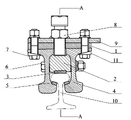
Fig. 1 faces one of sectional structure scheme drawing for interceptor.
Fig. 2 is the A-A sectional structure scheme drawing of Fig. 1.
Fig. 3 faces two of sectional structure scheme drawing for interceptor.
Fig. 4 is the A-A sectional structure scheme drawing of Fig. 3.
Fig. 5 faces three of sectional structure scheme drawing for interceptor.
Fig. 6 is the A-A sectional structure scheme drawing of Fig. 5.
Fig. 7 faces four of sectional structure scheme drawing for interceptor.
Fig. 8 faces five of sectional structure scheme drawing for interceptor.
Fig. 9 faces six of sectional structure scheme drawing for interceptor.
The specific embodiment
Embodiment 1: as Fig. 1, shown in Figure 2.Among the figure, 1 is clamping plate, and 2 is cushion block, and 3 are the industrial machinery upper friction plate, and 4 are the clamping rail, and 5 are industrial machinery friction lining down, and 6 is horizontal fastener, and 7 is vertical fastener, and 8 is jackscrew, and 9 is base-plate, and 10 is stock rail, 11 side's of being taper liner plates.Clamping plate 1, base-plate 9, clamping rail 4 is connected and fixed by vertical fastener 7.Jackscrew 8 passes clamping plate 1, the contact grooves of the base of base-plate 9 and clamping rail 4 and cushion block 2 upper surface corresponding positions, and fastening by nut.Cushion block 2 is installed in the centre of clamping rail 4.The web of the rail that horizontal fastener 6 passes cushion block 2 and clamping rail 4 is connected and fixed cushion block 2 and clamping rail 4.The banded draw-in groove of a sectional type is respectively arranged on 4 liang of relative lower jaw of rail head of lower surface and clamping rail surface of cushion block 2, every ribbon draw-in groove is divided into 3 draw-in grooves, friction lining 5 under mounting industrial machinery is used with upper friction plate 3 and industrial machinery respectively, industrial machinery is with the lower surface of outstanding cushion block after upper friction plate 3 compactings, and industrial machinery is with outstanding clamping rail rail head lower jaw surface after friction lining 5 compactings down.Industrial machinery all is ZP3-2 type asbestos friction sheet with upper friction plate 3 and industrial machinery with following friction lining 5.Jackscrew 8 compresses base-plate 9 from above, clamping plate 1, clamping rail 4 and cushion block 2, industrial machinery in the cushion block 2 lower surface draw-in grooves is pressed on the stock rail 10 with upper friction plate 3, laterally fastener 6 clamps from the web of the rail both sides of cushion block 2 and clamping rail 4, makes the industrial machinery on the relative lower jaw of clamping rail 4 rail heads surface press stock rail with following friction lining 5.Thereby industrial machinery compresses stock rail with following friction lining 5 from 3 faces with upper friction plate 3 and industrial machinery.The two ends of cushion block 2 are perpendicular.The upper surface of cushion block 2 has 2 grooves, is used to install jackscrew 8, and the middle part of cushion block 2 has 4 ellipse holes on the lower side, is used to install horizontal fastener 6.
Embodiment 2: shown in Figure 4 as Fig. 3, substantially the same manner as Example 1, difference is that an end of cushion block 2 is perpendiculars, and the other end has outwards outstanding right-angled trapezium body.The outstanding right-angled trapezium body of this right-angled trapezium body or sphenoid and rear end interceptor cushion block opposing end surface is imitative symmetrical complement configuration, and the two is stitched together and forms an oblong hexahedron or square hexahedron or parallelogram hexahedron.5 ellipse holes are arranged on the cushion block 2, and the relative position of the bottom surface of cushion block 2 and two rail head lower jaw inboards, clamping rail 4 lower ends respectively has 4 draw-in grooves.
Embodiment 3: as Fig. 5, shown in Figure 6.Substantially the same manner as Example 1, difference is: jackscrew 8 passes the contact grooves of the base and cushion block 2 upper surfaces of clamping plate 1 and clamping rail 4, and fastening by nut.The two ends of cushion block 2 respectively have an outwards outstanding right-angled trapezium body, and two right-angled trapezium bodies are imitative symmetrical complement configuration, and two right-angled trapezium bodies are stitched together and form an oblong hexahedron.In addition, the outwards outstanding right-angled trapezium body of the outwards outstanding right-angled trapezium body in this interceptor cushion block end and interceptor cushion block opposing end surface thereafter is imitative symmetrical complement configuration, and the two is stitched together and forms an oblong hexahedron.The upper surface of cushion block 2 has 2 grooves, is used to install jackscrew 8, and the middle and lower part of cushion block 2 has 3 ellipse holes, is used to install horizontal fastener 6.
Embodiment 4: as shown in Figure 7, substantially the same manner as Example 1, difference is: the lower surface of cushion block and clamping rail lower jaw surface all do not have draw-in groove, industrial machinery directly is adhesively fixed with upper friction plate 3 and fixes on the lower surface of cushion block, and industrial machinery is adhesively fixed with following friction lining 5 and fixes on clamping rail lower jaw surface.
Embodiment 5: as shown in Figure 8, substantially the same manner as Example 3, difference is: the lower surface of cushion block all has the banded draw-in grooves of two sectional types with the relative lower jaw of clamping rail two rail heads surface, and industrial machinery is complementary with corresponding draw-in groove respectively with following friction lining 5 with upper friction plate 3 and industrial machinery.
Embodiment 6: as shown in Figure 9, substantially the same manner as Example 1, difference is: the lower surface of cushion block has the banded draw-in groove of 3 sectional types, respectively there are the banded draw-in grooves of two sectional types on the relative lower jaw of clamping rail two rail heads surface, and industrial machinery is complementary with corresponding draw-in groove respectively with following friction lining with upper friction plate and industrial machinery.
Claims (5)
1. the interceptor of a stop buffer, comprise the clamping rail, fastener, jackscrew, clamping plate and two ends are the cushion block of perpendicular, it is characterized in that: the base of clamping plate and clamping rail is connected and fixed by vertical fastener, jackscrew passes base and the upper surface of cushion block or the contact grooves of cushion block upper surface corresponding position of clamping plate and clamping rail, and it is fastening by nut, cushion block is installed in the centre of clamping rail, laterally the fastener web of the rail that passes cushion block and clamping rail is connected and fixed cushion block and clamping rail, is fixed with the industrial machinery upper friction plate at the lower surface of cushion block, is fixed with friction lining under the industrial machinery usefulness on the relative lower jaw of the two rail heads surface of clamping rail.
2. the interceptor of stop buffer as claimed in claim 1, it is characterized in that: all be provided with draw-in groove at the lower surface of cushion block and the relative lower jaw of the two rail heads surface of clamping rail, with friction lining down respectively in the fixedly embedded corresponding draw-in groove, industrial machinery is with upper friction plate and industrial machinery lower surface and the clamping rail lower jaw surface with outstanding cushion block after the friction lining compacting down with upper friction plate and industrial machinery for industrial machinery.
3. the interceptor of stop buffer as claimed in claim 1 or 2 is characterized in that: industrial machinery is the industrial machinery asbestos friction sheet of friction coefficient between 0.2 ~ 0.6 with upper friction plate and industrial machinery with friction lining down.
4. the interceptor of stop buffer as claimed in claim 2, it is characterized in that: the cushion block lower surface has a ribbon or the banded draw-in groove of sectional type at least, the relative lower jaw of clamping rail two rail heads surface has the banded draw-in groove of a ribbon or sectional type respectively at least, industrial machinery with upper friction plate and industrial machinery with friction lining down respectively in the fixedly embedded corresponding draw-in groove.
5. the interceptor of stop buffer as claimed in claim 1, it is characterized in that: the two ends of cushion block are perpendicular, or an end of cushion block is a perpendicular, the other end has outwards outstanding right-angled trapezium body or sphenoid, or the two ends of cushion block all are provided with outwards outstanding right-angled trapezium body or sphenoid, and two of same cushion block two ends outwards outstanding right-angled trapezium bodies or sphenoid be the antisymmetry complementary configured each other, two right-angled trapezium bodies or sphenoid are stitched together and form an oblong hexahedron or square hexahedron or parallelogram hexahedron, in addition, an outwards outstanding right-angled trapezium body or the sphenoid in interceptor cushion block end is the antisymmetry complementary configured with right-angled trapezium body or the sphenoid that relative interceptor cushion block opposing end surface is outwards given prominence to, and the two is stitched together and forms an oblong hexahedron or square hexahedron or parallelogram hexahedron.
Priority Applications (1)
| Application Number | Priority Date | Filing Date | Title |
|---|---|---|---|
| CN 201010505788 CN101934801A (en) | 2010-10-14 | 2010-10-14 | Interceptor of vehicle stopper |
Applications Claiming Priority (1)
| Application Number | Priority Date | Filing Date | Title |
|---|---|---|---|
| CN 201010505788 CN101934801A (en) | 2010-10-14 | 2010-10-14 | Interceptor of vehicle stopper |
Publications (1)
| Publication Number | Publication Date |
|---|---|
| CN101934801A true CN101934801A (en) | 2011-01-05 |
Family
ID=43388438
Family Applications (1)
| Application Number | Title | Priority Date | Filing Date |
|---|---|---|---|
| CN 201010505788 Pending CN101934801A (en) | 2010-10-14 | 2010-10-14 | Interceptor of vehicle stopper |
Country Status (1)
| Country | Link |
|---|---|
| CN (1) | CN101934801A (en) |
Cited By (2)
| Publication number | Priority date | Publication date | Assignee | Title |
|---|---|---|---|---|
| CN105128887A (en) * | 2015-08-26 | 2015-12-09 | 中南大学 | Automatic pressing-plier-type anti-running iron shoe of railway vehicle |
| CN111674409A (en) * | 2020-07-13 | 2020-09-18 | 辽宁鑫丰矿业(集团)有限公司 | Explosion-proof motor rack rail clamping vehicle for coal mine |
Citations (7)
| Publication number | Priority date | Publication date | Assignee | Title |
|---|---|---|---|---|
| GB2060095A (en) * | 1979-08-13 | 1981-04-29 | Godwin Warren Eng Ltd | Brake Retarder Shoe |
| CN85105858A (en) * | 1984-11-29 | 1986-05-10 | 博格-华纳公司 | Asbestos-free friction elements |
| CN2145737Y (en) * | 1993-01-14 | 1993-11-10 | 沈阳铁路局科技开发公司 | Stop |
| US5836252A (en) * | 1995-02-28 | 1998-11-17 | A. Rawie Gmbh & Co. | Rail brake element |
| US5865122A (en) * | 1997-06-20 | 1999-02-02 | Western-Cullen-Hayes Inc. | Apparatus for attaching buffer stop to railroad track |
| CN1326882A (en) * | 2001-07-27 | 2001-12-19 | 杨志鸿 | Force increasing plug-in kick-up block for railway and its stopping method |
| CN201842111U (en) * | 2010-10-14 | 2011-05-25 | 郑州铁路局科学技术研究所 | Interceptor of stop buffer |
-
2010
- 2010-10-14 CN CN 201010505788 patent/CN101934801A/en active Pending
Patent Citations (7)
| Publication number | Priority date | Publication date | Assignee | Title |
|---|---|---|---|---|
| GB2060095A (en) * | 1979-08-13 | 1981-04-29 | Godwin Warren Eng Ltd | Brake Retarder Shoe |
| CN85105858A (en) * | 1984-11-29 | 1986-05-10 | 博格-华纳公司 | Asbestos-free friction elements |
| CN2145737Y (en) * | 1993-01-14 | 1993-11-10 | 沈阳铁路局科技开发公司 | Stop |
| US5836252A (en) * | 1995-02-28 | 1998-11-17 | A. Rawie Gmbh & Co. | Rail brake element |
| US5865122A (en) * | 1997-06-20 | 1999-02-02 | Western-Cullen-Hayes Inc. | Apparatus for attaching buffer stop to railroad track |
| CN1326882A (en) * | 2001-07-27 | 2001-12-19 | 杨志鸿 | Force increasing plug-in kick-up block for railway and its stopping method |
| CN201842111U (en) * | 2010-10-14 | 2011-05-25 | 郑州铁路局科学技术研究所 | Interceptor of stop buffer |
Cited By (3)
| Publication number | Priority date | Publication date | Assignee | Title |
|---|---|---|---|---|
| CN105128887A (en) * | 2015-08-26 | 2015-12-09 | 中南大学 | Automatic pressing-plier-type anti-running iron shoe of railway vehicle |
| CN111674409A (en) * | 2020-07-13 | 2020-09-18 | 辽宁鑫丰矿业(集团)有限公司 | Explosion-proof motor rack rail clamping vehicle for coal mine |
| CN111674409B (en) * | 2020-07-13 | 2024-05-31 | 辽宁鑫丰矿业(集团)有限公司 | Explosion-proof motor tooth rail clamping rail vehicle for coal mine |
Similar Documents
| Publication | Publication Date | Title |
|---|---|---|
| CN105274909B (en) | Steel rail vibration reduction fastener | |
| CN205130955U (en) | Pantagraph current collector for subway train | |
| CN201635000U (en) | High-damping and isolating plate-type bridge bearing | |
| CN207376376U (en) | Top locking type bilayer nonlinear vibration reduction fastener | |
| CN201842111U (en) | Interceptor of stop buffer | |
| CN101934801A (en) | Interceptor of vehicle stopper | |
| CN207633146U (en) | One kind can administrative region of a city railway double-layer vibration damping fastener easy to disassemble | |
| CN102213291B (en) | Penetrating shock absorber device | |
| CN205443809U (en) | Quick bullet strip ballastless track iron tie plate fastening systems | |
| CN205012161U (en) | Rail damping fastener | |
| CN201825667U (en) | Outdoor crane tilting prevention safety device | |
| CN207470673U (en) | A kind of emergent air spring assembly | |
| CN203729159U (en) | Vulcanized integrated rail fastener | |
| CN203864704U (en) | Bearing saddle pad and bearing saddle assembly | |
| CN203568690U (en) | Track connecting structure capable of bearing complex load | |
| CN207244354U (en) | A kind of rail fastener system | |
| CN206352255U (en) | A kind of bridge expanssion joint cover plate | |
| CN211850107U (en) | Height-adjustable friction damper | |
| CN203334183U (en) | Fastener structure for steel beam bridge open-bridge-floor track | |
| CN103243643A (en) | Horizontal elastic damping device for bridge | |
| CN205220260U (en) | Leaf spring fixing device | |
| CN202787061U (en) | Limiting rubber shock-isolation support | |
| CN203682908U (en) | Emergent anti-wind device of rail-type hoisting machinery | |
| CN202100656U (en) | Penetration type damper device | |
| CN203319474U (en) | Lift |
Legal Events
| Date | Code | Title | Description |
|---|---|---|---|
| C06 | Publication | ||
| PB01 | Publication | ||
| C10 | Entry into substantive examination | ||
| SE01 | Entry into force of request for substantive examination | ||
| C02 | Deemed withdrawal of patent application after publication (patent law 2001) | ||
| WD01 | Invention patent application deemed withdrawn after publication |
Application publication date: 20110105 |