CN101925665B - Light emitting device - Google Patents
Light emitting device Download PDFInfo
- Publication number
- CN101925665B CN101925665B CN2009801026966A CN200980102696A CN101925665B CN 101925665 B CN101925665 B CN 101925665B CN 2009801026966 A CN2009801026966 A CN 2009801026966A CN 200980102696 A CN200980102696 A CN 200980102696A CN 101925665 B CN101925665 B CN 101925665B
- Authority
- CN
- China
- Prior art keywords
- light
- phosphor
- emitting
- emitting device
- phosphors
- Prior art date
- Legal status (The legal status is an assumption and is not a legal conclusion. Google has not performed a legal analysis and makes no representation as to the accuracy of the status listed.)
- Active
Links
Images


Classifications
-
- C—CHEMISTRY; METALLURGY
- C09—DYES; PAINTS; POLISHES; NATURAL RESINS; ADHESIVES; COMPOSITIONS NOT OTHERWISE PROVIDED FOR; APPLICATIONS OF MATERIALS NOT OTHERWISE PROVIDED FOR
- C09K—MATERIALS FOR MISCELLANEOUS APPLICATIONS, NOT PROVIDED FOR ELSEWHERE
- C09K11/00—Luminescent, e.g. electroluminescent, chemiluminescent materials
- C09K11/08—Luminescent, e.g. electroluminescent, chemiluminescent materials containing inorganic luminescent materials
- C09K11/0883—Arsenides; Nitrides; Phosphides
-
- C—CHEMISTRY; METALLURGY
- C09—DYES; PAINTS; POLISHES; NATURAL RESINS; ADHESIVES; COMPOSITIONS NOT OTHERWISE PROVIDED FOR; APPLICATIONS OF MATERIALS NOT OTHERWISE PROVIDED FOR
- C09K—MATERIALS FOR MISCELLANEOUS APPLICATIONS, NOT PROVIDED FOR ELSEWHERE
- C09K11/00—Luminescent, e.g. electroluminescent, chemiluminescent materials
- C09K11/08—Luminescent, e.g. electroluminescent, chemiluminescent materials containing inorganic luminescent materials
- C09K11/77—Luminescent, e.g. electroluminescent, chemiluminescent materials containing inorganic luminescent materials containing rare earth metals
- C09K11/7728—Luminescent, e.g. electroluminescent, chemiluminescent materials containing inorganic luminescent materials containing rare earth metals containing europium
- C09K11/77347—Silicon Nitrides or Silicon Oxynitrides
-
- C—CHEMISTRY; METALLURGY
- C09—DYES; PAINTS; POLISHES; NATURAL RESINS; ADHESIVES; COMPOSITIONS NOT OTHERWISE PROVIDED FOR; APPLICATIONS OF MATERIALS NOT OTHERWISE PROVIDED FOR
- C09K—MATERIALS FOR MISCELLANEOUS APPLICATIONS, NOT PROVIDED FOR ELSEWHERE
- C09K11/00—Luminescent, e.g. electroluminescent, chemiluminescent materials
- C09K11/08—Luminescent, e.g. electroluminescent, chemiluminescent materials containing inorganic luminescent materials
- C09K11/77—Luminescent, e.g. electroluminescent, chemiluminescent materials containing inorganic luminescent materials containing rare earth metals
- C09K11/7728—Luminescent, e.g. electroluminescent, chemiluminescent materials containing inorganic luminescent materials containing rare earth metals containing europium
- C09K11/77348—Silicon Aluminium Nitrides or Silicon Aluminium Oxynitrides
-
- H—ELECTRICITY
- H10—SEMICONDUCTOR DEVICES; ELECTRIC SOLID-STATE DEVICES NOT OTHERWISE PROVIDED FOR
- H10H—INORGANIC LIGHT-EMITTING SEMICONDUCTOR DEVICES HAVING POTENTIAL BARRIERS
- H10H20/00—Individual inorganic light-emitting semiconductor devices having potential barriers, e.g. light-emitting diodes [LED]
- H10H20/80—Constructional details
- H10H20/85—Packages
- H10H20/851—Wavelength conversion means
- H10H20/8511—Wavelength conversion means characterised by their material, e.g. binder
- H10H20/8512—Wavelength conversion materials
- H10H20/8513—Wavelength conversion materials having two or more wavelength conversion materials
-
- H10W72/01515—
-
- H10W72/075—
-
- H10W72/07554—
-
- H10W72/20—
-
- H10W72/547—
-
- H10W72/59—
-
- H10W72/884—
-
- H10W72/90—
-
- H10W72/923—
-
- H10W72/9415—
-
- H10W74/00—
-
- H10W90/726—
-
- H10W90/756—
-
- Y—GENERAL TAGGING OF NEW TECHNOLOGICAL DEVELOPMENTS; GENERAL TAGGING OF CROSS-SECTIONAL TECHNOLOGIES SPANNING OVER SEVERAL SECTIONS OF THE IPC; TECHNICAL SUBJECTS COVERED BY FORMER USPC CROSS-REFERENCE ART COLLECTIONS [XRACs] AND DIGESTS
- Y10—TECHNICAL SUBJECTS COVERED BY FORMER USPC
- Y10S—TECHNICAL SUBJECTS COVERED BY FORMER USPC CROSS-REFERENCE ART COLLECTIONS [XRACs] AND DIGESTS
- Y10S362/00—Illumination
- Y10S362/80—Light emitting diode
-
- Y—GENERAL TAGGING OF NEW TECHNOLOGICAL DEVELOPMENTS; GENERAL TAGGING OF CROSS-SECTIONAL TECHNOLOGIES SPANNING OVER SEVERAL SECTIONS OF THE IPC; TECHNICAL SUBJECTS COVERED BY FORMER USPC CROSS-REFERENCE ART COLLECTIONS [XRACs] AND DIGESTS
- Y10—TECHNICAL SUBJECTS COVERED BY FORMER USPC
- Y10S—TECHNICAL SUBJECTS COVERED BY FORMER USPC CROSS-REFERENCE ART COLLECTIONS [XRACs] AND DIGESTS
- Y10S428/00—Stock material or miscellaneous articles
- Y10S428/917—Electroluminescent
Landscapes
- Chemical & Material Sciences (AREA)
- Inorganic Chemistry (AREA)
- Engineering & Computer Science (AREA)
- Materials Engineering (AREA)
- Organic Chemistry (AREA)
- Luminescent Compositions (AREA)
Abstract
Description
技术领域 technical field
本发明涉及能够发出颜色再现被改善了的光的发光装置,更加詳细地说涉及组合了半导体发光元件和荧光体的发光装置。The present invention relates to a light-emitting device capable of emitting light with improved color reproduction, and more specifically, to a light-emitting device in which a semiconductor light-emitting element and a phosphor are combined.
背景技术 Background technique
通过将从发光元件发出的光源光与被该光源光激发而能够发出与光源光不同的色相的光的波长变换部件进行组合,并利用光的混色原理,开发了能够发出各种波长的光的发光装置。例如,从发光元件射出从紫外光到相当于可见光的短波长侧区域的一次光,作为波长变换部件的R·G·B(Red·Green·Blue)荧光体被该出射光激发时,作为光的3原色的红色、蓝色、绿色这三原色被加色混合而得到白色光。By combining the light source light emitted from the light-emitting element with a wavelength conversion member that is excited by the light source light to emit light of a hue different from the light source light, and using the principle of color mixing of light, a device capable of emitting light of various wavelengths has been developed. light emitting device. For example, when the primary light from ultraviolet light to the short-wavelength region corresponding to visible light is emitted from the light-emitting element, and when the R·G·B (Red·Green·Blue) phosphor as the wavelength conversion member is excited by the emitted light, the The three primary colors of red, blue, and green are additively mixed to obtain white light.
基于该光的混色原理,利用LED(Light Emitting Diode)构成蓝色光,并通过将其与被该蓝色光激发而发出绿色和红色的光的荧光体组合,开发了能够发出白色光的发光装置。例如专利文献1所记载的荧光体是具有β型Si3N4结晶构造的氮化物或氮氧化物(β型SiAlON),并发出绿色光。专利文献1中还公开了一种照明装置,其通过用蓝色LED对该荧光体和作为红色荧光体的CaSiAlN3:Eu进行激发,将从LED和荧光体发出的光混合而发出白色光。Based on the color-mixing principle of this light, LEDs (Light Emitting Diode) are used to form blue light, and by combining it with phosphors that emit green and red light excited by the blue light, a light-emitting device capable of emitting white light has been developed. For example, the phosphor described in
将这样的照明装置的构造用作液晶显示器(LCD)、彩色布劳恩管(也称为阴极射线显像管,CRT)、投射式阴极射线管(PRT)、场发射显示器(FED)、荧光显示管(VFD)等背光用光源时,通常使用NTSC比作为用于在显示器上再现自然色调的指标。所谓NTSC比是指相对于将NTSC(National Television System Committee)所规定的红色、绿色、蓝色各颜色在XYZ表色式色度图中的色度座标((x、y)(红色(0.670,0.330)、绿色(0.210,0.710)、蓝色(0.140,0.080))相连接而得到的三角形的面积的比率。理想地,优选包含100%的NTSC比的颜色再现。迄今为止,在白色LED成为主流的手机用小型LCD中,亮度得到重视,而对颜色再现的要求较低,但最近用于笔记本电脑用LCD、大型TV用LCD的情况下,对颜色再现的要求度较高。The construction of such a lighting device is used as a liquid crystal display (LCD), a color Braun tube (also called a cathode ray tube, CRT), a projection cathode ray tube (PRT), a field emission display (FED), a fluorescent display tube In the case of a backlight light source such as (VFD), the NTSC ratio is generally used as an index for reproducing natural color tone on a display. The so-called NTSC ratio refers to the chromaticity coordinates ((x, y) (red (0.670 , 0.330), green (0.210, 0.710), blue (0.140, 0.080)) are connected to the ratio of the area of the triangle obtained. Ideally, it is preferred to include 100% NTSC color reproduction. So far, in white LED In small LCDs for mobile phones that have become the mainstream, brightness is important, and the requirements for color reproduction are relatively low. However, in the case of LCDs for notebook PCs and LCDs for large TVs recently, the requirements for color reproduction are high.
不过,在专利文献1所记载的照明装置中,β-SiAlON荧光体在540nm具有峰值波长,另外,CaAlSiN3:Eu荧光体主要在650~660nm附近具有峰值波长,因此难以准确地覆盖NTSC比的颜色再现范围。其结果是,存在无法实现高精度的影像显示这样的问题。However, in the lighting device described in
这样,在使用了现在大多采用的蓝色发光的发光元件、以及被该蓝色光激发而显示出黄色发光的荧光体的呈白色发光的发光装置中,颜色再现性(NTSC比)是70%左右,不能充分地满足对颜色再现的要求。另外,将蓝色发光、红色发光、绿色发光的LED进行组合来使用的白色LED虽达到NTSC比为100%,但由于各LED驱动电压和恶化特性的不同,存在难以增加使用寿命、降低成本的情况。在这样的背景下,当务之急是开发一种改善大型LCD用背光的颜色再现性(NTSC比)、且改善了亮度、使用寿命、成本的LCD背光用发光装置。In this way, in a white-emitting light-emitting device using a blue-emitting light-emitting element that is widely used today and a phosphor that is excited by the blue light to emit yellow light, the color reproducibility (NTSC ratio) is about 70%. , cannot fully meet the requirements for color reproduction. In addition, white LEDs that use a combination of blue, red, and green light-emitting LEDs have an NTSC ratio of 100%, but due to differences in the driving voltage and deterioration characteristics of each LED, it is difficult to increase the service life and reduce costs. Condition. Against such a background, it is urgent to develop a light-emitting device for LCD backlights that improves the color reproducibility (NTSC ratio) of backlights for large LCDs and improves brightness, service life, and cost.
例如,专利文献2所记载的发光装置是将发出蓝色光的发光元件和被该蓝色光激发的绿色发光的荧光体((Sr,Ba)2SiO4:Eu)以及红色发光的荧光体(CaAlSiN3:Eu)组合而成的。(Sr,Ba)2SiO4:Eu荧光体能够使峰值波长变化到520~600nm,其结果是,因为能够调整相对的颜色再现的范围,所以能够得到宽范围的颜色再现。不过,在该发光装置中,荧光体本身急剧恶化,因此存在用途受到限制的问题。For example, the light-emitting device described in
并且,作为着眼于LCD的颜色再现性(NTSC比)的现有技术,例如能够列举出专利文献3的液晶显示装置。对于该装置,作为背光光源,在505~535nm的范围具有光谱峰值。该波长是通过绿色荧光体来实现的,作为该荧光体的活化剂,公开了包括铕、钨、锡、锑、锰中的任一种的活化剂。另外,作为具体的绿色荧光体,记载有MgGa2O4:Mn、Zn2SiO4:Mn。不过,在上述荧光体与峰值波长为430~480nm的发光元件一起被搭载的情况下,该荧光体的激发波长与发光元件的峰值波长不一致,则其发光效率显著降低。即,作为实用级的荧光体,不仅要求满足颜色再现,还要求优异的耐受性、以及由激发光源产生的发光效率高。In addition, as the prior art focusing on the color reproducibility (NTSC ratio) of LCD, for example, the liquid crystal display device of
另外,即使是颜色再现和发光特性均理想的荧光体,也由于荧光体在发光装置中的搭载区域的偏在,有可能各成分光中放射量的混合会变得不均匀,从而在作为整体的混合光中引发颜色不均。其结果是,例如LED间的色调的偏差变大,难以恒定地保持LCD的质量。即,作为整个发光装置的发光特性较大地依存于荧光体的混合状态。In addition, even with phosphors with ideal color reproduction and luminous characteristics, due to unevenness in the mounting area of the phosphors in the light-emitting device, there is a possibility that the mixing of the emission amounts in each component light will become uneven, and the overall Color unevenness caused by mixed light. As a result, for example, the variation in color tone between LEDs increases, making it difficult to maintain the quality of the LCD at a constant level. That is, the light emission characteristics of the entire light emitting device largely depend on the mixing state of the phosphors.
另外,LCD背光用的滤光器有各种滤光器,由于滤光器的波长的吸收率不同,所以要求具有与LCD背光用的滤光器特性相符的峰值波长的光源。不过,在绿色发光的荧光体中,还未开发出满足发光特性、耐久性等优异的特性并且在维持了该特性的状态下能使峰值波长变化的绿色发光的荧光体。例如,上述引用文献1的β型SiAlON荧光体虽然发光特性优异,在发出于540nm附近具有峰值波长的光的情况下亮度很高,但若使峰值波长从540nm附近变化,则亮度显著降低。因此,引用文献1的β型SiAlON不适于具有与比540nm短的短波的530nm~535nm附近的峰值波长相符的特性的滤光器。因而,寻求在530nm~535nm附近具有峰值波长、发光特性等优异的绿色发光的荧光体。另外,寻求具有与LCD背光用的滤光器特性相符的峰值波长的光源、或能够调整成以NTSC为基准的所期望的颜色再现的光源。这需要如上所述那样降低一个光源中的颜色不均来改善发光特性的同时,也考虑到集合了各光源而形成的宽范围区域的发光的特性。即,由于对各光源的投入电力的差别或发光特性的差别等,有可能在由点光源的集聚构成的面发光中产生颜色偏差,故寻求能改善这一问题的光源。即,重要的是与各光源的发光条件或滤色器相对应地调整荧光体的发光波长。In addition, there are various kinds of filters for LCD backlight, and since the absorption rate of the wavelength of the filter is different, a light source having a peak wavelength matching the characteristics of the filter for LCD backlight is required. However, among green-emitting phosphors, no green-emitting phosphor has been developed that satisfies excellent properties such as light-emitting characteristics and durability and can change the peak wavelength while maintaining these properties. For example, the β-type SiAlON phosphor of
如上所述,在激发光源和荧光体的组合中,除了发光亮度、颜色再现范围和可靠性(荧光体的恶化)等荧光体本身的特性之外,还在作为发光装置的产品级中,要求进一步改良成品率(颜色偏差)和成本等,此为当前的现状。As mentioned above, in the combination of the excitation light source and the phosphor, in addition to the characteristics of the phosphor itself such as the luminous brightness, the color reproduction range, and the reliability (deterioration of the phosphor), it is also required at the product level as a light-emitting device. It is the current status quo to further improve the yield (color deviation) and cost, etc.
专利文献1:日本专利3921545号公报Patent Document 1: Japanese Patent No. 3921545
专利文献2:日本专利3940162号公报Patent Document 2: Japanese Patent No. 3940162
专利文献3:日本特开2003-121838号公报Patent Document 3: Japanese Patent Laid-Open No. 2003-121838
专利文献4:日本特开2004-287323号公报Patent Document 4: Japanese Patent Laid-Open No. 2004-287323
发明内容 Contents of the invention
本发明是为了解决上述问题而做成的。本发明的主要的目的在于提供一种能够将颜色再现范围调整成所期望的范围、且能够实现宽范围的颜色再现区域的发光装置。The present invention is made to solve the above problems. A main object of the present invention is to provide a light-emitting device capable of adjusting the color reproduction range to a desired range and realizing a wide color reproduction range.
第1发明所涉及的发光装置具有能够发出光的发光元件、和被从该发光元件发出的光激发而能发出波长与该发光元件发出光的波长不同的可见光的两种以上的荧光体。这两种以上的荧光体包含:选自下述通式(I)和(Ⅱ)中的至少1种以上的氮化物荧光体的红色发光荧光体、以及至少1种以上的绿色发光荧光体。另外,这2种以上的荧光体中,真比重是3.00~4.30的荧光体群的各自的真比重与该荧光体群的真比重的平均值之差在该荧光体群的真比重的平均值±16%以内,并且,该2种以上的荧光体中真比重为3.00~4.30的荧光体群为90wt%以上。The light-emitting device according to the first invention includes a light-emitting element capable of emitting light, and two or more phosphors that are excited by the light emitted from the light-emitting element to emit visible light having a wavelength different from that of light emitted by the light-emitting element. These two or more phosphors include: a red light-emitting phosphor of at least one nitride phosphor selected from the following general formulas (I) and (II), and at least one green light-emitting phosphor. In addition, among these two or more kinds of phosphors, the difference between the true specific gravity of each phosphor group whose true specific gravity is 3.00 to 4.30 and the average value of the true specific gravity of the phosphor group is within the average value of the true specific gravity of the phosphor group. It is within ±16%, and among the two or more kinds of phosphors, the phosphor group having a true specific gravity of 3.00 to 4.30 is 90 wt% or more.
MwAlxSiyBzN((2/3)w+x+(4/3)y+z):Eu2+ (I)M w Al x Si y B z N ((2/3)w+x+(4/3)y+z) :Eu 2+ (I)
通式(I)中,M是选自Mg、Ca、Sr和Ba中的至少一种,w、x、y、z分别满足0.5≤w≤3、x=1、0.5≤y≤3、0≤z≤0.5。In the general formula (I), M is at least one selected from Mg, Ca, Sr and Ba, and w, x, y, z satisfy 0.5≤w≤3, x=1, 0.5≤y≤3, 0 respectively ≤ z ≤ 0.5.
MpSiqN((2/3)p+(4/3)q):Eu2+ (II)M p Si q N ((2/3)p+(4/3)q) :Eu 2+ (II)
通式(II)中,M是选自Mg、Ca、Sr和Ba中的至少一种,p、q分别满足1.5≤p≤2.5、4.5≤q≤5.5。In the general formula (II), M is at least one selected from Mg, Ca, Sr and Ba, and p and q respectively satisfy 1.5≤p≤2.5 and 4.5≤q≤5.5.
另外,第一发明所涉及的发光装置具有能够发出光的发光元件、和被从该发光元件发出的光激发而能发出波长与该发光元件发出光的波长不同的可见光的3种以上的荧光体。这3种以上的荧光体包含:具有选自下述通式(I)和(Ⅱ)的至少1种以上的氮化物荧光体的红色发光荧光体和以下述通式(III)和(IV)表示的至少2种以上的绿色发光荧光体。这2种以上的绿色发光荧光体形成的峰值波长为529nm~535nm。另外,这些3种以上的荧光体中,真比重是3.00~4.30的荧光体群的各自的真比重与该荧光体群的真比重的平均值之差在所述荧光体群的真比重的平均值的±16%以内,并且,所述3种以上的荧光体中真比重为3.00~4.30的所述荧光体群为90wt%以上。In addition, the light-emitting device according to the first invention has a light-emitting element capable of emitting light, and three or more kinds of phosphors that are excited by the light emitted from the light-emitting element and can emit visible light having a wavelength different from that of the light emitted by the light-emitting element. . These three or more kinds of phosphors include: red light-emitting phosphors having at least one nitride phosphor selected from the following general formulas (I) and (II) and the following general formulas (III) and (IV) Indicates at least two or more green-emitting phosphors. The peak wavelengths formed by these two or more kinds of green light-emitting phosphors are 529 nm to 535 nm. In addition, among these three or more kinds of phosphors, the difference between the true specific gravity of each phosphor group whose true specific gravity is 3.00 to 4.30 and the average value of the true specific gravity of the phosphor group is equal to the average value of the true specific gravity of the phosphor group. The value is within ±16%, and the phosphor group having a true specific gravity of 3.00 to 4.30 among the three or more phosphors is 90 wt% or more.
MwAlxSiyBzN((2/3)w+x+(4/3)y+z):Eu2+ (I)M w Al x Si y B z N ((2/3)w+x+(4/3)y+z) :Eu 2+ (I)
通式(I)中,M是选自Mg、Ca、Sr和Ba中的至少一种,w、x、y、z分别满足0.5≤w≤3、x=1、0.5≤y≤3、0≤z≤0.5。In the general formula (I), M is at least one selected from Mg, Ca, Sr and Ba, and w, x, y, z satisfy 0.5≤w≤3, x=1, 0.5≤y≤3, 0 respectively ≤ z ≤ 0.5.
MpSiqN((2/3)p+(4/3)q):Eu2+ (II)M p Si q N ((2/3)p+(4/3)q) :Eu 2+ (II)
通式(II)中,M是选自Mg、Ca、Sr和Ba中的至少一种,p、q分别满足1.5≤p≤2.5、4.5≤q≤5.5。In the general formula (II), M is at least one selected from Mg, Ca, Sr and Ba, and p and q respectively satisfy 1.5≤p≤2.5 and 4.5≤q≤5.5.
MxMgSizOaXb:Eu2+ (III)M x MgSi z O a X b :Eu 2+ (III)
通式(III)中,M是选自Ca、Sr、Ba、Zn、Mn中的至少一种,X是选自F、Cl、Br、I中的至少一种,x、z、a、b分别满足6.5≤x<8.0、3.7≤z≤4.3、a=x+1+2z-b/2、1.0≤b≤1.9。In the general formula (III), M is at least one selected from Ca, Sr, Ba, Zn, Mn, X is at least one selected from F, Cl, Br, I, x, z, a, b 6.5≤x<8.0, 3.7≤z≤4.3, a=x+1+2z-b/2, 1.0≤b≤1.9 are respectively satisfied.
SicAldOfNg:Eu2+ (IV)Si c Al d O f N g :Eu 2+ (IV)
通式(IV)中,c、d、f、g分别满足c+d=6、5.0≤c<6、0<d≤1.0、0.001<f≤1、7≤g<8。In the general formula (IV), c, d, f, and g satisfy c+d=6, 5.0≤c<6, 0<d≤1.0, 0.001<f≤1, 7≤g<8, respectively.
另外,优选荧光体群的平均粒径的差在±20%以内。In addition, it is preferable that the difference in the average particle diameter of the phosphor group is within ±20%.
另外,优选荧光体群的平均粒径为5um~30um。In addition, it is preferable that the average particle diameter of the phosphor group is 5 um to 30 um.
另外,优选各荧光体群的表面被实施了相同的表面处理,以使其表面状态均匀。In addition, it is preferable that the surface of each phosphor group is subjected to the same surface treatment so as to make the surface state uniform.
另外,荧光体群表面也可以含有至少包含Si的化合物。In addition, the surface of the phosphor group may contain a compound containing at least Si.
另外,绿色发光荧光体由Ca8MgSi4O16Cl2-δ:Eu(0≤δ≤1.0)和Si6-xAlxOyN8-y:Eu(x≤1、y≤1)构成。另外,优选红色发光荧光体由(Ca1-xSrx)2Si5N8:Eu(0≤x≤1.0)和(Ca1-xSrx)AlSiByN3+y:Eu(0≤x≤1.0、0≤y≤0.5)构成。In addition, the green light-emitting phosphor is composed of Ca 8 MgSi 4 O 16 Cl 2-δ :Eu (0≤δ≤1.0) and Si 6-x Al x O y N 8-y :Eu (x≤1, y≤1) constitute. In addition, it is preferable that the red light-emitting phosphor is composed of (Ca 1-x Sr x ) 2 Si 5 N 8 :Eu (0≤x≤1.0) and (Ca 1-x Sr x )AlSiB y N 3+y :Eu(0≤ x≤1.0, 0≤y≤0.5).
另外,优选其特征在于,发光元件从近紫外线到蓝色波长区域具有峰值波长。In addition, it is preferable that the light-emitting element has a peak wavelength in a near-ultraviolet to blue wavelength region.
另外,优选发光元件在445nm~470nm具有峰值波长。In addition, it is preferable that the light-emitting element has a peak wavelength at 445 nm to 470 nm.
另外,优选通过将多个色相的光混色,能够发出白色光;通过干涉单一的峰值波长或在50nm以内存在的2种以上的峰值波长而构成一个色相。In addition, it is preferable that white light can be emitted by mixing light of a plurality of hues, and one hue is formed by interfering with a single peak wavelength or two or more peak wavelengths existing within 50 nm.
另外,优选2种以上的荧光体中,绿色发光荧光体为60wt%~95wt%或/和上述红色发光荧光体为5wt%~40wt%。In addition, among the two or more phosphors, it is preferable that the green light-emitting phosphor is 60 wt % to 95 wt % or/and the red light emitting phosphor is 5 wt % to 40 wt %.
根据本发明的发光装置,在发光装置所采用的荧光体中极多地含有真比重类似的荧光体,从而能够使荧光体的沉降状态一致,并使荧光体大致均等地扩散。由此,能够获得以下发光装置,其能够极大地减少各荧光体的放射区域的偏在,并能够发出颜色不均被降低了的混色光。另外,通过设定各种荧光体的混合比例,能控制各色相的波长区域。进而通过将被控制的各色相组合,能够得到将全部混色光的颜色再现范围扩大的宽色域的发光装置。According to the light-emitting device of the present invention, phosphors used in the light-emitting device contain a large number of phosphors with similar true specific gravity, so that the sedimentation state of the phosphors can be made uniform, and the phosphors can be diffused substantially uniformly. Accordingly, it is possible to obtain a light-emitting device capable of greatly reducing the unevenness of the emission regions of the respective phosphors and capable of emitting mixed-color light with reduced color unevenness. In addition, by setting the mixing ratio of various phosphors, it is possible to control the wavelength region of each hue. Furthermore, by combining the controlled hues, it is possible to obtain a light-emitting device with a wide color gamut that expands the color reproduction range of all mixed-color lights.
附图说明 Description of drawings
图1是实施方式1所涉及的发光装置,图1(a)表示立体图,图1(b)表示(a)的沿IB-IB’线的剖视图。Fig. 1 is a light emitting device according to
图2表示蓝色LED的发光光谱图。FIG. 2 shows a light emission spectrum diagram of a blue LED.
图3表示CaAlSiByN3+y:Eu:Eu荧光体的发光光谱图。Fig. 3 shows the emission spectrum of the CaAlSiB y N 3+y :Eu:Eu phosphor.
图4表示Ca2Si5N8:Eu荧光体的发光光谱图。Fig. 4 is a graph showing the emission spectrum of the Ca 2 Si 5 N 8 :Eu phosphor.
图5表示Ca8MgSi4O16Cl2-δ:Eu荧光体的发光光谱图。Fig. 5 shows the emission spectrum diagram of Ca 8 MgSi 4 O 16 Cl 2-δ :Eu phosphor.
图6表示Si6-xAlxOyN8-y:Eu荧光体的发光光谱图。Fig. 6 shows the emission spectrum of Si 6-x Al x O y N 8-y :Eu phosphor.
图7表示荧光体和LED的色度图。Fig. 7 shows chromaticity diagrams of phosphors and LEDs.
图8表示实施例1的发光装置的发光光谱图。FIG. 8 is a graph showing the emission spectrum of the light emitting device of Example 1. FIG.
图9表示实施例2的发光装置的发光光谱图(蓝色450nm激发)Fig. 9 shows the emission spectrum diagram (blue 450nm excitation) of the light-emitting device of
图10表示实施例2的发光装置的发光光谱图(蓝色460nm激发)。Fig. 10 is a graph showing the emission spectrum of the light-emitting device of Example 2 (blue excitation at 460 nm).
图11表示实施例3的发光装置的发光光谱图。FIG. 11 shows an emission spectrum diagram of the light emitting device of Example 3. FIG.
图12表示实施例4的发光装置的发光光谱图。FIG. 12 is a graph showing the emission spectrum of the light emitting device of Example 4. FIG.
图13表示使用了实施方式1的情况下的荧光体沉降状态的示意图。FIG. 13 is a schematic diagram showing a sedimentation state of phosphors when
图14表示比较例1的荧光体沉降状态的示意图。FIG. 14 is a schematic view showing the sedimentation state of phosphors in Comparative Example 1. FIG.
图15是表示实施例3b的发光装置的颜色偏差的图。Fig. 15 is a graph showing color variation of the light-emitting device of Example 3b.
图16是表示比较例1的发光装置的颜色偏差的图。FIG. 16 is a graph showing color variation of the light-emitting device of Comparative Example 1. FIG.
图17表示搭载了蓝色LED和YAG:Ce的发光装置的发光光谱图。FIG. 17 is a graph showing the emission spectrum of a light emitting device equipped with blue LEDs and YAG:Ce.
图18是表示搭载450nmLED和YAG:Ce的发光装置的NTSC比的色度图。18 is a chromaticity diagram showing the NTSC ratio of a light-emitting device equipped with 450 nm LED and YAG:Ce.
图19是表示搭载460nmLED和YAG:Ce的发光装置的NTSC比的色度图。FIG. 19 is a chromaticity diagram showing the NTSC ratio of a light-emitting device equipped with 460 nm LED and YAG:Ce.
图20是表示实施例1a的发光装置的NTSC比的色度图。Fig. 20 is a chromaticity diagram showing the NTSC ratio of the light-emitting device of Example 1a.
图21是表示实施例2a的发光装置的NTSC比的色度图。Fig. 21 is a chromaticity diagram showing the NTSC ratio of the light-emitting device of Example 2a.
图22是表示实施例3a的发光装置的NTSC比的色度图。Fig. 22 is a chromaticity diagram showing the NTSC ratio of the light-emitting device of Example 3a.
图23是表示实施例4a的发光装置的NTSC比的色度图。Fig. 23 is a chromaticity diagram showing the NTSC ratio of the light-emitting device of Example 4a.
图24是表示实施例1b的发光装置的NTSC比的色度图。Fig. 24 is a chromaticity diagram showing the NTSC ratio of the light-emitting device of Example 1b.
图25是表示实施例2b的发光装置的NTSC比的色度图。Fig. 25 is a chromaticity diagram showing the NTSC ratio of the light-emitting device of Example 2b.
图26是表示实施例3b的发光装置的NTSC比的色度图。Fig. 26 is a chromaticity diagram showing the NTSC ratio of the light-emitting device of Example 3b.
图27是表示实施例4b的发光装置的NTSC比的色度图。Fig. 27 is a chromaticity diagram showing the NTSC ratio of the light-emitting device of Example 4b.
图28是实施方式2所涉及的发光装置,图28(a)表示立体图,图28(b)表示剖视图。28 is a light emitting device according to
图29是实施方式3所涉及的发光装置的剖视图。FIG. 29 is a cross-sectional view of a light emitting device according to
图30是实施方式4所涉及的发光装置的剖视图。30 is a cross-sectional view of a light emitting device according to
图31是实施方式5所涉及的发光装置的剖视图。31 is a cross-sectional view of a light emitting device according to
图32是实施例8~12的荧光体的发光光谱图。FIG. 32 is a graph showing emission spectra of phosphors in Examples 8 to 12. FIG.
符号说明Symbol Description
1、20、30、40、60、发光装置,2、发光元件(LED),3、3a、3b、3c、3d、荧光体(荧光体),4、引线框,4a、引线框电极,5、接合线,6、树脂,6a、树脂,8、发光层,9、电极,10、杯状件,11、模制件,12、组件(Package),13、保护元件,14、凹部,15、导线电极,16、支撑体,17、组件,18、密封部件,31、罩1, 20, 30, 40, 60, light emitting device, 2, light emitting element (LED), 3, 3a, 3b, 3c, 3d, phosphor (phosphor), 4, lead frame, 4a, lead frame electrode, 5 , bonding wire, 6, resin, 6a, resin, 8, light-emitting layer, 9, electrode, 10, cup, 11, molding, 12, package (Package), 13, protective element, 14, recess, 15 , wire electrode, 16, support body, 17, component, 18, sealing part, 31, cover
具体实施方式 Detailed ways
下面根据附图来说明本发明的实施方式。但是,以下所示的实施方式仅举例说明用于使本发明的技术构思具体化的发光装置,本发明并未将发光装置特定于以下装置。另外,权利要求所示的部件并不一定特定为具体实施方式的部件。特别是实施方式所记载的构成部件的尺寸、材质、形状、其相对配置等,只要没有特别的特定记载,就没有将本发明的范围仅限定于此的意思,这些实施方式只不过是说明例。另外,为了清楚地说明各附图所示的部件的大小和位置关系等,有时放大表示。另外,在以下的说明中,相同的名称、符号表示相同或同质的部件,适当地省略详细说明。进一步地,对于构成本发明的各要素,可以用相同的部件构成多个要素,也可以形成为用一个部件兼作多个要素,相反地,也能够用多个部件分担地实现一个部件的功能。另外,在一部分实施例、实施方式中所说明的内容也能够利用于其他实施例、实施方式等。Embodiments of the present invention will be described below with reference to the drawings. However, the embodiments shown below are merely examples of light-emitting devices for actualizing the technical concept of the present invention, and the present invention does not specify the light-emitting devices to the following devices. In addition, the components shown in the claims are not necessarily specified as components of the specific embodiment. In particular, the dimensions, materials, shapes, and relative arrangements of components described in the embodiments are not intended to limit the scope of the present invention thereto unless otherwise specified, and these embodiments are merely illustrative examples. . In addition, in order to clearly explain the size, positional relationship, etc. of components shown in each drawing, they may be shown enlarged. In addition, in the following description, the same name and code|symbol represent the same or a homogeneous member, and detailed description is abbreviate|omitted suitably. Furthermore, with respect to each element constituting the present invention, multiple elements may be constituted by the same member, or a single member may serve as multiple elements. Conversely, the function of one member may be shared by multiple members. In addition, the contents described in some examples and embodiments can also be used in other examples, embodiments, and the like.
另外,色名和色度座标之间的关系、光的波长范围和单色光的色名之间的关系等只要没有特别的限制,就按照JIS Z8110。具体来说,380nm~455nm是蓝紫色,455nm~485nm是蓝色,485nm~495nm是蓝绿色,495nm~548nm是绿色,548nm~573nm是黄绿色,573nm~584nm是黄色,584nm~610nm是橙红色,610nm~780nm是红色。In addition, the relationship between the color name and chromaticity coordinates, the relationship between the wavelength range of light and the color name of monochromatic light, etc., are in accordance with JIS Z8110 unless otherwise specified. Specifically, 380nm-455nm is blue-purple, 455nm-485nm is blue, 485nm-495nm is blue-green, 495nm-548nm is green, 548nm-573nm is yellow-green, 573nm-584nm is yellow, 584nm-610nm is orange-red , 610nm ~ 780nm is red.
(实施方式1)(Embodiment 1)
实施方式1所涉及的发光装置60如图1所示。图1(a)表示发光装置60的立体图,图1(b)表示(a)的沿IB-IB’线的发光装置60的剖视图。如图1(b)所示,图的发光装置60具有:发出光的发光元件2、和被该发光元件2的发出光激发而能发出与该发出光的波长不同的至少两种以上的荧光体3。A
即,发光装置60具备多个荧光体3。实施方式1的荧光体3包含:具有选自下述通式(I)和(Ⅱ)中的至少1种以上的氮化物荧光体的红色发光荧光体、以及1种以上的绿色发光荧光体,在该被搭载的所有荧光体中的、真比重是3.00~4.30的荧光体中,该真比重的平均值A与各荧光体3的真比重之差d为真比重的平均值A±16%以内(d≤|0.16A|),进一步优选为±11%以内(d≤|0.11A|)。在此,所谓真比重的平均值是指,在被搭载的所有的荧光体中的真比重为3.00~4.30的荧光体中,将种类不同的各荧光体所具有的真比重相加所得的和除以该荧光体种类数所得到的值。另外,具有90wt%以上、进一步优选具有95wt%以上的真比重为3.00~4.30的荧光体。另外,真比重用岛津制作所的Micromeritics AccuPyc 1330测量。测量原理是定容积膨胀法。在装置里存在一定容积的试料室和膨胀室,向试料室投入试样,只向该试料室导入气体来提高压力。之后,打开试料室和膨胀室之间的阀门,利用阀门开闭前后的压力的不同而根据压力求出试样的密度。That is, the
MwAlxSiyBzN((2/3)w+x+(4/3)y+z):Eu2+ (I)M w Al x Si y B z N ((2/3)w+x+(4/3)y+z) :Eu 2+ (I)
通式(I)中,M是选自Mg、Ca、Sr和Ba中的至少一种,w、x、y、z分别满足0.5≤w≤3、x=1、0.5≤y≤3、0≤z≤0.5。In the general formula (I), M is at least one selected from Mg, Ca, Sr and Ba, and w, x, y, z satisfy 0.5≤w≤3, x=1, 0.5≤y≤3, 0 respectively ≤ z ≤ 0.5.
MpSiqN((2/3)p+(4/3)q):Eu2+ (II)M p Si q N ((2/3)p+(4/3)q) :Eu 2+ (II)
通式(II)中,M是选自Mg、Ca、Sr和Ba中的至少一种,p、q分别满足1.5≤p≤2.5、4.5≤q≤5.5。In the general formula (II), M is at least one selected from Mg, Ca, Sr and Ba, and p and q respectively satisfy 1.5≤p≤2.5 and 4.5≤q≤5.5.
另外,绿色发光荧光体优选具有下述通式(III)和(Ⅳ)的两种以上的荧光体。优选由该两种以上的绿色发光荧光体形成的峰值波长为529nm~535nm。由此,能够适当地同具有与529nm~535nm的峰值波长相符的特性的滤光器组合。In addition, the green light-emitting phosphor preferably has two or more phosphors of the following general formulas (III) and (IV). Preferably, the peak wavelength formed by the two or more green light-emitting phosphors is 529 nm to 535 nm. Accordingly, it is possible to appropriately combine with an optical filter having a characteristic corresponding to a peak wavelength of 529 nm to 535 nm.
MxMgSizOaXb:Eu2+ (III)M x MgSi z O a X b :Eu 2+ (III)
通式(III)中,M是选自Ca、Sr、Ba、Zn、Mn中的至少一种,X是选自F、Cl、Br、I中的至少一种,x、z、a、b分别满足6.5≤x<8.0、3.7≤z≤4.3、a=x+1+2z-b/2、1.0≤b≤1.9。In the general formula (III), M is at least one selected from Ca, Sr, Ba, Zn, Mn, X is at least one selected from F, Cl, Br, I, x, z, a, b 6.5≤x<8.0, 3.7≤z≤4.3, a=x+1+2z-b/2, 1.0≤b≤1.9 are respectively satisfied.
SicAldOfNg:Eu2+ (IV)Si c Al d O f N g :Eu 2+ (IV)
通式(IV)中,c、d、f、g分别满足c+d=6、5.0≤c<6、0<d≤1.0、0.001<f≤1、7≤g<8。In the general formula (IV), c, d, f, and g satisfy c+d=6, 5.0≤c<6, 0<d≤1.0, 0.001<f≤1, 7≤g<8, respectively.
另外,优选荧光体3的平均粒径的差在±20%以内。通过只使在真比重和粒径方面具有上述特有条件的荧光体混合,并将该荧光体搭载在发光装置60中,使得荧光体3在发光装置60内的混合状态均匀化,其结果是,能够从发光装置60得到颜色不均被极大地降低了的混色光。In addition, it is preferable that the difference in the average particle diameter of the
另外,在构成发光装置的混色光的各成分光中,对于各色相的具体的波长区域,蓝色区域为445nm~470nm,绿色区域为510nm~550nm,红色区域为600nm~670nm,优选在该波长区域内具有各成分光的峰值波长。由此,能实现具有宽范围的颜色再现的发光。另外,发光装置所使用的绿色发光荧光体的绿色和红色发光荧光体的红色不需要存在上述的JIS Z8110规定的色名和色度座标之间的关系。另外,各色相能够由单一或多个发光元件或荧光体的放射光构成。在由多个放射光构成一个色相的情况下,优选使处于50nm以内的两种以上的峰值波长干涉而得到一个色相。由此,降低色调的偏差而能得到高的特性的发光。在发光装置60中,采用真比重为3.00~4.30的荧光体,各荧光体3中的各真比重的平均值之差在±16%以内。另外,荧光体3的平均粒径是5um~30um。In addition, in each component light of the mixed color light constituting the light-emitting device, for the specific wavelength region of each hue, the blue region is 445nm-470nm, the green region is 510nm-550nm, and the red region is 600nm-670nm. There are peak wavelengths of each component light in the region. Thereby, light emission with a wide range of color reproduction can be realized. In addition, the green color of the green light-emitting phosphor used in the light-emitting device and the red color of the red light-emitting phosphor do not need to have the relationship between the color name and the chromaticity coordinates stipulated in the above-mentioned JIS Z8110. In addition, each hue can be composed of light emitted from a single or a plurality of light-emitting elements or phosphors. When one hue is constituted by a plurality of emitted lights, it is preferable to obtain one hue by interfering two or more peak wavelengths within 50 nm. Thereby, variation in color tone is reduced, and high characteristic light emission can be obtained. In the light-emitting
另外,来自发光装置的发光是通过对具有蓝、绿、红等各色相的成分光进行混色而得到的。实施方式1所涉及的发光装置具有:发出从近紫外到蓝色区域的光的发光元件2、吸收该发光元件2的发出光的至少一部分并发出绿色的光的荧光体和发出红色的光的荧光体。这些三原色的发光被混色而从发光装置60发出白色光。具体而言,发光元件2采用在445nm~470nm具有峰值波长的LED,其发光光谱如图2所示。在图2中记载有在450nm和460nm具有峰值波长的两种LED的发光光谱。下面列举出被该LED激发的红色发光的荧光体和绿色发光的荧光体的例子。In addition, the light emitted from the light emitting device is obtained by color-mixing component light having hues of blue, green, red, and the like. The light-emitting device according to
(红色发光荧光体)(Red Luminescent Phosphor)
作为红色发光荧光体,列举出被Eu活化、含有第Ⅱ族元素M、Si、Al、B和N的以下列通式(I)表示的氮化物荧光体。Examples of red light-emitting phosphors include nitride phosphors activated by Eu and containing Group II elements M, Si, Al, B, and N represented by the following general formula (I).
MwAlxSiyBzN((2/3)w+x+(4/3)y+z):Eu2+ (I)M w Al x Si y B z N ((2/3)w+x+(4/3)y+z) :Eu 2+ (I)
通式(I)中,M是选自Mg、Ca、Sr和Ba中的至少一种,w、x、y、z分别满足0.5≤w≤3、x=1、0.5≤y≤3、0≤z≤0.5。通式(I)所表示的红色发光荧光体的发光峰值波长为630nm~670nm。In the general formula (I), M is at least one selected from Mg, Ca, Sr and Ba, and w, x, y, z satisfy 0.5≤w≤3, x=1, 0.5≤y≤3, 0 respectively ≤ z ≤ 0.5. The emission peak wavelength of the red light-emitting phosphor represented by the general formula (I) is 630 nm to 670 nm.
作为上述(I)的荧光体的一个例子,存在由MwAlSiBzN((2/3)w+x+(7/3)+z):Eu2+所表示的荧光体。式中、M是选自Mg、Ca、Sr和Ba中的至少1种,w的范围为0.5≤w≤1.5,z的范围为0≤z≤0.5。更优选由CaAlSiByN3+y:Eu(0≤y≤0.1,实际的组成是y=0.005)表示,其比重是3.24g/cm3。该CaAlSiByN3+y:Eu荧光体的发光光谱图如图3所示。图3的曲线是被460nm激发时的发光光谱图,在650nm处具有峰值波长。As an example of the phosphor of the above (I), there is a phosphor represented by M w AlSiB z N ((2/3)w+x+(7/3)+z) :Eu 2+ . In the formula, M is at least one selected from Mg, Ca, Sr and Ba, the range of w is 0.5≤w≤1.5, and the range of z is 0≤z≤0.5. It is more preferably represented by CaAlSiB y N 3+y :Eu (0≤y≤0.1, the actual composition is y=0.005), and its specific gravity is 3.24 g/cm 3 . The emission spectrum of the CaAlSiB y N 3+y :Eu phosphor is shown in FIG. 3 . The curve in Fig. 3 is a luminescence spectrum diagram when excited by 460nm, and has a peak wavelength at 650nm.
另外,以下的通式(Ⅱ)所表示的红色发光荧光体的其他例子如下所示。In addition, other examples of the red light-emitting phosphor represented by the following general formula (II) are as follows.
MpSiqN((2/3)p+(4/3)q):Eu2+ (II)M p Si q N ((2/3)p+(4/3)q) :Eu 2+ (II)
通式(II)中,M是选自Mg、Ca、Sr和Ba中的至少一种,p、q分别满足1.5≤p≤2.5、4.5≤q≤5.5。通式(Ⅱ)所表示的红色发光荧光体的发光峰值波长为600nm~650nm。In the general formula (II), M is at least one selected from Mg, Ca, Sr and Ba, and p and q respectively satisfy 1.5≤p≤2.5 and 4.5≤q≤5.5. The emission peak wavelength of the red light-emitting phosphor represented by the general formula (II) is 600 nm to 650 nm.
另外,作为优选的氮化物荧光体,通式(Ⅱ)由Ca2Si5N8:Eu2+表示。其比重是3.08g/cm3。作为其他的组成,由(Ca,Sr)2Si5N8:Eu2+表示,其比重是3.59g/cm3。Ca2Si5N8:Eu2+的荧光体被460nm激发的发光光谱图如图4所示。In addition, as a preferable nitride phosphor, the general formula (II) is represented by Ca 2 Si 5 N 8 :Eu 2+ . Its specific gravity is 3.08 g/cm 3 . The other composition is represented by (Ca,Sr) 2 Si 5 N 8 :Eu 2+ , and its specific gravity is 3.59 g/cm 3 . The luminescence spectrum of Ca 2 Si 5 N 8 :Eu 2+ phosphor excited by 460 nm is shown in FIG. 4 .
上述通式(I)、(Ⅱ)的氮化物荧光体被Eu活化,但也能够利用选自Sc、Tm、Yb、Y、La、Ce、Pr、Nd、Sm、Gd、Tb、Dy、Ho、Er、Lu的至少一种以上的稀土类元素来取代Eu的一部分。The nitride phosphors of the above-mentioned general formulas (I), (II) are activated by Eu, but it is also possible to utilize , Er, and Lu at least one or more rare earth elements to replace a part of Eu.
在使用Ca作为M的情况下,Ca优选单独地使用。其中,也能够利用Sr、Mg、Ba、Sr和Ba等来取代Ca的一部分。能够利用Sr来取代Ca的一部分来调整氮化物荧光体的发光波长的峰值。In the case of using Ca as M, Ca is preferably used alone. However, a part of Ca can also be substituted with Sr, Mg, Ba, Sr, Ba, or the like. The peak of the emission wavelength of the nitride phosphor can be adjusted by substituting a part of Ca with Sr.
对于这些荧光体,Si也优选单独地使用,但也能够用第Ⅳ族元素即C、Ge来取代Si的一部分。在只使用了Si的情况下,能得到廉价且结晶性良好的氮化物荧光体。For these phosphors, Si alone is also preferably used, but a part of Si can be substituted with C and Ge which are Group IV elements. When only Si is used, an inexpensive nitride phosphor with good crystallinity can be obtained.
作为活化剂的Eu,优选单独使用,但也可以利用Sc、Tm、Yb、Y、La、Ce、Pr、Nd、Sm、Gd、Tb、Dy、Ho、Er、Lu来取代Eu的一部分。在利用其他元素取代Eu的一部分的情况下,其他元素作为共活化剂而起作用。这样一来,能使色调变化,并能进行发光特性的调整。Eu as an activator is preferably used alone, but a part of Eu may be substituted by Sc, Tm, Yb, Y, La, Ce, Pr, Nd, Sm, Gd, Tb, Dy, Ho, Er, or Lu. When a part of Eu is replaced with another element, the other element functions as a co-activator. In this way, it is possible to change the color tone and adjust the emission characteristics.
氮化物荧光体还可以含有1~500ppm以下的选自由Cu、Ag、Au构成的第I族元素、由Ga、In构成的第Ⅲ族元素、由Ti、Zr、Hf、Sn、Pb构成的第Ⅳ族元素、由P、Sb、Bi构成的第V族元素以及由S构成的第Ⅵ族元素中的至少1种以上的元素。这些元素也与第1族元素同样地在制造工序中烧制时飞散,因此烧制后的添加量少于最初向原料添加的添加量。因此,优选将添加到原料中的量调整成1000ppm以下。通过添加这些元素,能进行发光效率的调整。The nitride phosphor may also contain 1 to 500 ppm or less of Group I elements consisting of Cu, Ag, and Au, Group III elements consisting of Ga, In, and Group III elements consisting of Ti, Zr, Hf, Sn, and Pb. At least one element selected from Group IV elements, Group V elements consisting of P, Sb, and Bi, and Group VI elements consisting of S. These elements also scatter during firing in the manufacturing process similarly to the
另外,在氮化物荧光体中,优选Fe、Ni、Cr、Ti、Nb、Sm和Yb的摩尔浓度相对于M的摩尔浓度为0.01以下。原因在于,在含有大量Fe、Ni、Cr、Ti、Nb、Sm和Yb时,发光亮度会降低。In addition, in the nitride phosphor, the molar concentration of Fe, Ni, Cr, Ti, Nb, Sm, and Yb relative to the molar concentration of M is preferably 0.01 or less. The reason is that when a large amount of Fe, Ni, Cr, Ti, Nb, Sm, and Yb is contained, the luminance of light emission decreases.
作为红色荧光体的上述通式(I)、(Ⅱ)的氮化物荧光体,其详细情况后述,但其满足与以下的绿色发光荧光体的真比重差的上述条件。因而,优选将含有(I)、(Ⅱ)中的任一个或含有这两者的多个荧光体作为红色荧光体与下述的绿色发光荧光体一起用作红色区域的成分光。The details of the nitride phosphors of the above-mentioned general formulas (I) and (II) as red phosphors will be described later, but they satisfy the above-mentioned condition that the true specific gravity is different from that of the following green light-emitting phosphors. Therefore, it is preferable to use a plurality of phosphors containing either one or both of (I) and (II) as a red phosphor as a component light in the red region together with a green light-emitting phosphor described below.
(绿色发光荧光体)(Green Luminescent Phosphor)
另外,作为绿色发光荧光体的例子,能够列举出被Eu活化的由下列通式(III)所表示的卤素氧化物荧光体。In addition, as an example of the green light-emitting phosphor, a halogen oxide phosphor represented by the following general formula (III) activated by Eu can be mentioned.
MxEuyMgSizOaXb (III)M x Eu y MgSi z O a X b (III)
通式(III)中,M是选自Ca、Sr、Ba、Zn、Mn中的至少一种,X是选自F、Cl、Br、I中的至少一种,x、y、z、a、b分别满足6.5≤x<8.0、0.01≤y≤2.0、3.7≤z≤4.3、a=x+y+1+2z-b/2、1.0≤b≤1.9。In the general formula (III), M is at least one selected from Ca, Sr, Ba, Zn, Mn, X is at least one selected from F, Cl, Br, I, x, y, z, a and b satisfy 6.5≤x<8.0, 0.01≤y≤2.0, 3.7≤z≤4.3, a=x+y+1+2z-b/2, 1.0≤b≤1.9, respectively.
另外,上述通式(III)也可以用将荧光体的母体与作为活化材料的Eu分开表示的下面的通式MxMgSizOaXb:Eu2+(M是选自Ca、Sr、Ba、Zn、Mn中的至少一种,X是选自F、Cl、Br、I中的至少一种,x、z、a、b分别满足6.5≤x<8.0、3.7≤z≤4.3、a=x+1+2z-b/2、1.0≤b≤1.9。)来表示。In addition, the above general formula (III) can also be represented by the following general formula M x MgS z O a X b : Eu 2+ (M is selected from Ca, Sr, At least one of Ba, Zn, Mn, X is at least one selected from F, Cl, Br, I, x, z, a, b respectively satisfy 6.5≤x<8.0, 3.7≤z≤4.3, a =x+1+2z-b/2, 1.0≤b≤1.9.) to represent.
通式(III)的荧光体含有选自Ca、Sr、Ba、Zn及Mn的至少一种元素,更优选含有Ca。在含有Ca的情况下,也可以使用将Ca的一部分用Mn、Sr、Ba取代后的荧光体。另外,通式(III)的荧光体含有选自Si、Ge和Sn的至少一种元素,更优选含有Si。在含有Si的情况下,也可以使用将Si的一部分用Ge、Sn取代后的荧光体。另外,通式(III)的荧光体含有选自F、Cl、Br和I的至少一种元素,更优选含有Cl。在含有Cl的情况下,也可以使用将Cl的一部分用F、Br和I取代后的荧光体。作为通式(III)的优选荧光体,列举出Ca8MgSi4O16Cl2-δ:Eu2+(0≤δ≤1,δ表示Cl的组成偏差),其比重为3.29g/cm3。The phosphor of the general formula (III) contains at least one element selected from Ca, Sr, Ba, Zn and Mn, more preferably Ca. When Ca is contained, a phosphor obtained by substituting a part of Ca with Mn, Sr, or Ba can also be used. In addition, the phosphor of the general formula (III) contains at least one element selected from Si, Ge, and Sn, and more preferably contains Si. When Si is contained, a phosphor obtained by substituting a part of Si with Ge or Sn can also be used. In addition, the phosphor of the general formula (III) contains at least one element selected from F, Cl, Br, and I, more preferably Cl. When Cl is contained, a phosphor obtained by substituting a part of Cl with F, Br, and I can also be used. As a preferred phosphor of the general formula (III), Ca 8 MgSi 4 O 16 Cl 2-δ :Eu 2+ (0≤δ≤1, δ represents the composition deviation of Cl) is listed, and its specific gravity is 3.29 g/cm 3 .
上述通式(III)所表示的荧光体在从510nm~530nm的绿色区域到黄色区域的波长范围具有发光峰值波长。另外,作为通式(III)的一个例子而表示的Ca8MgSi4O16Cl2-δ:Eu2+的由460nm激发的发光光谱如图5所示。The phosphor represented by the above general formula (III) has an emission peak wavelength in the wavelength range from the green region to the yellow region of 510 nm to 530 nm. In addition, the emission spectrum excited at 460 nm of Ca 8 MgSi 4 O 16 Cl 2-δ :Eu 2+ represented as an example of the general formula (III) is shown in FIG. 5 .
进而,作为绿色发光荧光体的其他例子,列举出用以下通式表示的荧光体。Furthermore, as another example of the green light-emitting phosphor, phosphors represented by the following general formulas are mentioned.
SicAldEueOfNg (IV)Si c Al d Eu e O f N g (IV)
通式(IV)中,c、d、e、f、g分别满足c+d+e=6、5.0≤c<6、0<d≤1.0、0.001≤e≤0.06、0.001<f≤1、7≤g<8。In the general formula (IV), c, d, e, f, and g respectively satisfy c+d+e=6, 5.0≤c<6, 0<d≤1.0, 0.001≤e≤0.06, 0.001<f≤1, 7≤g<8.
另外,上述通式(IV)也可以用将荧光体的母体和作为活化材料的Eu分开表示的下面的通式SicAldOfNg:Eu2+(c、d、f、g分别满足c+d=6、5.0≤c<6、0<d≤1.0、0.001<f≤1、7≤g<8。)表示。In addition, the above general formula (IV) can also be represented by the following general formula SicAldOfNg which separates the matrix of the phosphor and Eu as the active material: Eu 2+ (c, d , f , g respectively Satisfy c+d=6, 5.0≤c<6, 0<d≤1.0, 0.001<f≤1, 7≤g<8.) representation.
该荧光体含有选自Ca、Sr、Ba、Zn及Mn的至少一种元素,更优选含有Ca。在含有Ca的情况下,也可以使用将Ca的一部分用Mn、Sr、Ba取代后的荧光体。另外,通式(IV)所表示的绿色荧光体在530nm~555nm的波长范围具有发光峰值波长。作为荧光体(IV)的具体的一个例子,由Si6-xAlxOyN8-y:Eu2+表示,其具有β型SiAlON的结晶结构。该荧光体的由460nm激发的发光光谱如图6所示。并且,作为这样的β型SiAlON的具体的组成,能够列举出Si5.775Al0.21Eu0.015O0.023N7.910、Si5.80Al0.185Eu0.015O0.023N7.918等,但并不限定于此。另外,Si5.775Al0.21Eu0.015O0.023N7.910的比重是3.23g/cm3。The phosphor contains at least one element selected from Ca, Sr, Ba, Zn and Mn, more preferably Ca. When Ca is contained, a phosphor obtained by substituting a part of Ca with Mn, Sr, or Ba can also be used. In addition, the green phosphor represented by the general formula (IV) has an emission peak wavelength in a wavelength range of 530 nm to 555 nm. A specific example of the phosphor (IV) is represented by Si 6-x Al x O y N 8-y :Eu 2+ , which has a crystal structure of β-type SiAlON. The emission spectrum excited by 460 nm of this phosphor is shown in FIG. 6 . Furthermore, examples of specific compositions of such β-type SiAlON include Si 5.775 Al 0.21 Eu 0.015 O 0.023 N 7.910 , Si 5.80 Al 0.185 Eu 0.015 O 0.023 N 7.918 , and the like, but are not limited thereto. In addition, the specific gravity of Si 5.775 Al 0.21 Eu 0.015 O 0.023 N 7.910 is 3.23 g/cm 3 .
上述(III)和(IV)的绿色发光的荧光体含有将Eu作为必要组分的至少1种稀土类元素。稀土类是钪、钇和镧各元素的合计17种元素的总称,其中Eu最优选。也可以使用将Eu的一部分用Ce、Pr、Nd、Sm、Tb、Dy、Ho、Er、Tm、Yb取代后的荧光体。更优选也可以使用将Eu的一部分用Ce、Pr、Nd、Sm、Tb、Dy、Ho、Tm取代后的荧光体。The green light-emitting phosphors of (III) and (IV) above contain at least one rare earth element including Eu as an essential component. Rare earth is a general term for a total of 17 elements including scandium, yttrium, and lanthanum, among which Eu is most preferable. A phosphor obtained by substituting a part of Eu with Ce, Pr, Nd, Sm, Tb, Dy, Ho, Er, Tm, or Yb can also be used. More preferably, a phosphor obtained by substituting a part of Eu with Ce, Pr, Nd, Sm, Tb, Dy, Ho, or Tm can also be used.
另外,上述(III)和(IV)的绿色发光的荧光体通过调整各自的配合量,能够调整由(III)和(IV)形成的峰值波长。In addition, the above-mentioned green light-emitting phosphors of (III) and (IV) can adjust the peak wavelengths of (III) and (IV) by adjusting the respective compounding amounts.
另外,作为上述以外的绿色的荧光体,也可以使用以通式SrSi2O2N2:Eu2+、SrGa2S4:Eu2+、Ba3Si6O12-xN2+y:Eu2+(-2<x<2、-2<y<2、x和y表示O、N的组成偏差)所表示的荧光体。SrSi2O2N2:Eu2+绿色荧光体在从530nm~555nm的绿色区域到黄色区域的波长范围具有发光峰值波长,其真比重是3.67g/cm3。另外,SrGa2S4:Eu2+绿色荧光体在530nm~540nm具有发光峰值波长,其真比重是3.62g/cm3。此外,Ba3Si6O12-xN2+y:Eu2+绿色荧光体在从520nm~540nm的绿色区域到黄色区域的波长范围具有发光峰值波长,其真比重是4.18g/cm3。In addition, as green phosphors other than those mentioned above, those represented by the general formula SrSi 2 O 2 N 2 :Eu 2+ , SrGa 2 S 4 :Eu 2+ , Ba 3 Si 6 O 12-x N 2+y : Phosphor represented by Eu 2+ (-2<x<2, -2<y<2, x and y represent the composition deviation of O and N). The SrSi 2 O 2 N 2 :Eu 2+ green phosphor has an emission peak wavelength in the wavelength range from 530nm to 555nm in the green region to the yellow region, and its true specific gravity is 3.67g/cm 3 . In addition, the SrGa 2 S 4 :Eu 2+ green phosphor has a luminous peak wavelength at 530 nm to 540 nm, and its true specific gravity is 3.62 g/cm 3 . In addition, the Ba 3 Si 6 O 12-x N 2+y :Eu 2+ green phosphor has an emission peak wavelength in the wavelength range from 520nm to 540nm in the green region to the yellow region, and its true specific gravity is 4.18g/cm 3 .
实施方式的荧光体的制造方法没有特别的限定,能采用公知的手段。以下示出一例。将荧光体的组分所含有的元素的单质、氧化物、碳酸盐或氮化物等作为起始原料,称量上述各原料以使其具有规定的组分比。另外,还在原料中适当地添加各种添加元素、硼等添加材料作为助熔剂,采用混合机以湿式或干式进行混合。由此,能够促进固相反应,形成均匀大小的粒子。另外,混合机除了采用工业上通常采用的球磨机之外,还可以使用振动磨机、辊磨机、喷磨机等粉碎机来进行粉碎来增大比表面积。另外,为了使粉末的比表面积处于一定范围,能够使用工业上通常采用的沉降槽、水力旋流器、离心分离器等湿式分离机、以及旋风分离器、空气分离器等干式分级机来进行分级。将上述混合的原料装到SiC、石英、氧化铝、BN等坩锅中,在N2、H2的还原气氛中进行烧制。烧制气氛也能够使用氩气气氛、氨气气氛等。以规定的温度和时间进行烧制。将烧制后的材料粉碎、分散、过滤等而得到目标荧光体粉末。固液分离能够利用过滤、吸滤、加压过滤、离心分离、倾析等工业上通常采用的方法来进行。干燥能够利用真空干燥机、热风加热烘干机、锥形干燥机、旋转式蒸发器等工业上通常采用的装置来进行。The method for producing the phosphor of the embodiment is not particularly limited, and known methods can be employed. An example is shown below. Elementary substances, oxides, carbonates, nitrides, etc. of elements contained in the components of the phosphor are used as starting materials, and each of the above-mentioned materials is weighed so as to have a predetermined composition ratio. In addition, various additive elements and additive materials such as boron are appropriately added to the raw materials as a flux, and mixed by a wet or dry mixer using a mixer. Thereby, the solid-phase reaction can be promoted, and particles of uniform size can be formed. In addition, in addition to the ball mill commonly used in the industry, the mixer can also use a vibrating mill, a roller mill, a jet mill and other pulverizers for pulverization to increase the specific surface area. In addition, in order to keep the specific surface area of the powder within a certain range, wet separators such as settling tanks, hydrocyclones, and centrifugal separators commonly used in industry, and dry classifiers such as cyclone separators and air separators can be used. Grading. The above-mentioned mixed raw materials are put into crucibles such as SiC, quartz, alumina, BN, etc., and fired in a reducing atmosphere of N 2 and H 2 . As the firing atmosphere, an argon atmosphere, an ammonia atmosphere, or the like can also be used. Firing is carried out at the specified temperature and time. The fired material is pulverized, dispersed, filtered, etc. to obtain the target phosphor powder. Solid-liquid separation can be performed by methods commonly used industrially, such as filtration, suction filtration, pressure filtration, centrifugation, and decantation. Drying can be carried out by an industrially commonly used device such as a vacuum dryer, a hot-air heating dryer, a cone dryer, and a rotary evaporator.
荧光体的表面处理能采用使用了硅烷偶联剂等使表面带有有机系的官能团的表面处理、或用无机系的二氧化硅、氧化铝等氧化物、或磷酸盐、硫酸盐、碳酸盐等覆盖表面的表面处理。在用硅烷偶联剂进行表面处理的情况下,能使用市售的硅烷偶联剂,采用已知的干式或湿式方法进行表面处理,能调整硅树脂组合物等透光性树脂和各种荧光体的润湿性。通过调整润湿性,也能够调整沉降状态。另外,作为表面处理二氧化硅的例子,有使用硅酸四乙酯(TEOS),使用氨等催化剂,在荧光体的表面使二氧化硅层析出的例子。在使用该硅酸四乙酯的情况下,也能采用已知的干式或湿式方法进行。通过与硅烷偶联剂的情况相同地调整各种荧光体的表面的状态,能调整与透光性树脂的润湿性、以及沉降状态。The surface treatment of the phosphor can be carried out by using a silane coupling agent, etc. to make the surface with organic functional groups, or by using inorganic oxides such as silica, alumina, or phosphate, sulfate, or carbonic acid. Surface treatment that coats the surface with salt, etc. In the case of surface treatment with a silane coupling agent, a commercially available silane coupling agent can be used, and a known dry or wet method can be used for surface treatment, and it is possible to adjust translucent resins such as silicone resin compositions and various Phosphor wettability. By adjusting the wettability, the sedimentation state can also be adjusted. In addition, as an example of surface-treated silica, there is an example in which a silica layer is deposited on the surface of the phosphor using tetraethyl silicate (TEOS) and a catalyst such as ammonia. In the case of using the tetraethyl silicate, known dry or wet methods can also be used. By adjusting the state of the surface of various phosphors similarly to the case of the silane coupling agent, the wettability with the translucent resin and the state of sedimentation can be adjusted.
(粒径)(particle size)
另外,考虑到搭载于发光装置,荧光体的粒径优选处于5um~30um的范围,更优选处于5um~20um。另外,优选高频率地含有具有该平均粒径值的荧光体。此外,优选在粒子分布方面也分布在狭窄的范围的荧光体。通过使用具有粒径和粒度分布的偏差小、且具有光学特性优异的特征的大粒径的荧光体,能得到进一步抑制颜色不均、具有良好的色调的发光装置。因而,只要是具有上述范围的粒径的荧光体,光的吸收率和变换效率就很高。另一方面,具有比5um小的粒径的荧光体存在容易形成凝聚体的倾向。上述粒径是指通过F.S.S.S.No(Fisher Sub Sieve Sizer’s No)的空气透过法得到的平均粒径。具体来说,是在气温为25℃、湿度为70%的环境下,量取1cm3左右的试样,装到专用的管状容器中之后,通入一定压力的干燥空气,从压差读取比表面积,并换算成平均粒径的值。In addition, in consideration of being mounted on a light-emitting device, the particle size of the phosphor is preferably in the range of 5 um to 30 um, more preferably in the range of 5 um to 20 um. In addition, it is preferable to contain phosphors having this average particle diameter value at a high frequency. In addition, phosphors that are also distributed within a narrow range in terms of particle distribution are preferable. By using a large-particle-diameter phosphor characterized by less variation in particle diameter and particle size distribution and having excellent optical properties, it is possible to obtain a light-emitting device that further suppresses color unevenness and has good color tone. Therefore, as long as the phosphor has a particle diameter within the above-mentioned range, the light absorption rate and conversion efficiency are high. On the other hand, phosphors having a particle size smaller than 5 μm tend to easily form aggregates. The said particle diameter means the average particle diameter obtained by the air permeation method of FSSSNo (Fisher Sub Sieve Sizer's No). Specifically, in an environment with a temperature of 25°C and a humidity of 70%, take a sample of about 1 cm 3 , put it in a special tubular container, and then pass it into a certain pressure of dry air, and read it from the pressure difference. The specific surface area is converted into the value of the average particle diameter.
下面对本发明的一个实施方式所涉及的发光装置进行详细描述。搭载了发光元件的发光装置存在炮弹型和表面安装型等各种形式。通常而言,所谓炮弹型是指将构成外表面的树脂的形状形成为炮弹型的发光装置。另外,所谓表面安装型是指将发光元件和树脂填充到凹状的收纳部内而形成的发光装置。图1的发光装置60是表面安装型中的1种即侧发光(side view)型的发光装置。所谓侧视型是指从与发光装置的载置面邻接的侧面侧发光的类型的发光装置,能形成得更薄。但是,发光装置的形态并不限定于此,也可以构成为以往所使用的顶发光(top view)型或其他结构。The light emitting device according to one embodiment of the present invention will be described in detail below. There are various types of light-emitting devices equipped with light-emitting elements, such as a shell type and a surface-mount type. Generally, the term "cannonball" refers to a light emitting device in which the shape of the resin constituting the outer surface is shaped like a cannonball. In addition, the term "surface-mount type" refers to a light-emitting device formed by filling a concave-shaped housing portion with a light-emitting element and resin. The
(概要)(summary)
在发光装置中,在插入有正负一对的外部电极并关闭了的模具内,从处于与壳体的主面相对的下面侧的浇口流入熔融了的聚邻苯二甲酰胺树脂,使之固化而形成壳体。壳体具有能收纳发光元件的开口部,以使正负外部电极的一个主面从该开口部底面露出的方式一体地成形。从壳体侧面露出的正负外部电极的各外部导线部在与发光面相反的一侧的面的两端部被向内侧折弯。利用环氧树脂将主波长峰值为450nm的LED芯片焊接在这样形成的开口部的底面上,并用电线将该LED芯片与各外部电极电连接。同样地还制作了具有460nm的主波长峰值的LED芯片。In the light-emitting device, the molten polyphthalamide resin is poured from the gate on the bottom side opposite to the main surface of the case into the closed mold in which the positive and negative pairs of external electrodes are inserted, so that solidified to form a shell. The case has an opening capable of accommodating the light emitting element, and is integrally formed such that one main surface of the positive and negative external electrodes is exposed from the bottom surface of the opening. The external lead portions of the positive and negative external electrodes exposed from the side surfaces of the case are bent inwardly at both end portions of the surface opposite to the light emitting surface. An LED chip having a dominant wavelength peak of 450 nm was soldered to the bottom surface of the thus formed opening with epoxy resin, and the LED chip was electrically connected to each external electrode with wires. Similarly, an LED chip having a dominant wavelength peak of 460 nm was produced.
在该发光装置中,在具有开口于上方的凹部的发光元件搭载壳体的凹部的底面,利用芯片焊接剂粘贴有发光元件,该发光元件上覆盖有分散了荧光体的透光性树脂。发光元件的上部电极通过第1导电性部件而与第1外部电极电连接,下部电极通过第2导电性部件而与第2外部电极电连接。另外,在发光元件搭载壳体的凹部的内表面覆盖有光反射材料。In this light-emitting device, a light-emitting element covered with a light-transmitting resin in which a phosphor is dispersed is attached to the bottom surface of a recessed portion of a light-emitting element mounting case having a recessed portion opening upward using a die-bonding agent. The upper electrode of the light emitting element is electrically connected to the first external electrode through the first conductive member, and the lower electrode is electrically connected to the second external electrode through the second conductive member. In addition, the inner surface of the concave portion of the light-emitting element mounting case is covered with a light-reflecting material.
下面说明图1的发光装置60。发光装置60具有凹部14和被收纳在该凹部的内部的发光元件2,而且在凹部14内被含有荧光体3的树脂填充。该凹部14是组件17的一部分,即组件17由凹部14以及与该凹部14连结的支撑体16构成。如图1(b)所示,正负导线电极15介于凹部14和支撑体16这两者之间,从而构成凹部14中的发光元件2的载置面。并且,导线电极15露出于组件17的外表面侧,沿着组件17的外形设置。发光元件2搭载在凹部14内的导线电极15上而与导线电极15电连接,发光元件2利用该导线电极15能从外部接受电力的供给而发光。图1(a)是安装了发光装置60的通常的状态,即,以与载置有发光元件2的面正交的宽幅的面作为底面而进行载置。利用上述构造,完成了能从与发光元件的安装面大致平行的方向、即从与发光装置的载置面邻接的侧面发光的发光装置60。Next, the
具体而言,组件17以正负两导线电极15的一端部插入到组件17中的方式被一体地成型。即,组件17在主表面侧具有能收纳发光元件2的凹部14,正的导线电极15的一端部和负的导线电极15的一端部彼此分开且各自的主表面露出地设在该凹部14的底面上。在正负导线电极15之间填充有绝缘性的成型材料。另外,在本发明中,形成于发光装置的主侧面的发光面的形状不限于图1所示的矩形状,也可以是椭圆状。通过形成为各种形状,能够形成如下所述的发光装置,其在保持形成凹部14的组件侧壁部的机械强度的同时,能够尽可能地增大发光面,即使薄型化,也能宽范围地照射。Specifically, the
另外,在实施方式1的发光装置60中,正负导线电极15以其另一端从组件侧面突出的方式插入。该导线电极15突出的部分朝着与组件17的主表面相对的背面侧折弯,或朝着与上述主面垂直的安装面侧折弯。另外,对于形成凹部14的内壁面的形状没有特别的限定,但在载置发光元件4的情况下,优选以内径向开口侧逐渐变大的方式形成为锥形状。由此,能够将从发光元件2的端面发出的光高效地向发光观测面方向取出。另外,为了提高光的反射,优选在凹部的内壁面上实施银等金属的镀覆以具有光反射功能。In addition, in the light-emitting
实施方式1的发光装置60在如上所述构成的组件1的凹部14内载置有发光元件2。并且以覆盖凹部内的发光元件2的方式填充有透光性树脂,从而形成密封部件18。在该透光性树脂中含有荧光体3。透光性树脂优选使用硅树脂组合物,但也能采用环氧树脂组合物、丙烯酸树脂组合物等具有透光性的绝缘树脂组合物。In the light-emitting
(发光元件)(light emitting element)
发光元件能发出从紫外线区域到可见光区域的光。特别是使用在240nm~480nm、更优选在445nm~470nm具有发光峰值波长的发光元件,优选具有发光层,该发光层能够发出具有能使荧光物质高效地激发的发光波长的光。通过使用该范围的激发光源,能提供发光效率高的荧光体。另外,通过在激发光源上利用半导体发光元件,能够得到高效率且输出相对于输入的的线性度较高、即使在机械冲击下也很稳定的发光装置。可见光的短波长侧区域的光主要为蓝色光区域。在此,本说明书中的近紫外线到可见光的短波长区域是指240nm~500nm附近的区域。另外,下面作为发光元件以氮化物半导体发光元件为例子进行说明,但不限于此。The light emitting element can emit light from the ultraviolet region to the visible region. In particular, a light-emitting element having an emission peak wavelength of 240nm to 480nm, more preferably 445nm to 470nm is used, and preferably has a light emitting layer capable of emitting light having a light emission wavelength capable of efficiently exciting fluorescent substances. By using an excitation light source in this range, a phosphor with high luminous efficiency can be provided. In addition, by using a semiconductor light-emitting element as an excitation light source, it is possible to obtain a light-emitting device with high efficiency, high linearity of output with respect to input, and stability even under mechanical shock. The light in the short-wavelength side region of visible light is mainly in the blue light region. Here, the short-wavelength region from near-ultraviolet to visible light in this specification refers to a region in the vicinity of 240 nm to 500 nm. In addition, a nitride semiconductor light-emitting element will be described below as an example of a light-emitting element, but it is not limited thereto.
具体而言,发光元件优选是包含In或Ga的氮化物半导体元件。原因在于,实施例所涉及的荧光体利用近紫外线到蓝色波长区域附近的激发光而强烈地发光,因此需要该波长区域的发光元件。至少一个以上的荧光体被来自发光元件的光激发,显示出规定的发光颜色。另外,该发光元件能够使发光光谱宽度变窄,从而能够使荧光体高效地激发,同时也能够从发光装置发出实质上对色调变化不会产生影响的发光光谱。Specifically, the light emitting element is preferably a nitride semiconductor element containing In or Ga. This is because the phosphors according to the examples emit intensely with excitation light in the vicinity of the wavelength range from near ultraviolet to blue, and therefore light-emitting elements in this wavelength range are required. At least one or more phosphors are excited by light from the light emitting element to exhibit a predetermined emission color. In addition, the light-emitting element can narrow the width of the emission spectrum to efficiently excite the phosphor, and at the same time, it is possible to emit the emission spectrum from the light-emitting device that does not substantially affect the color tone change.
另外,实施方式1所涉及的发光元件2采用作为氮化物半导体元件的一个例子的LED芯片。另外,发光元件2能适当利用公知的发光元件,但形成为具备荧光物质的发光装置时,优选能发出使该荧光物质激发的光的半导体发光元件。作为这样的半导体发光元件,存在ZnSe、InGaN、掺杂有各种杂质的GaN等各种半导体,作为一个例子,能适当地列举出能够发出可使荧光物质高效地激发的短波长的光的氮化物半导体(InXAlYGa1-X-YN、0≤X、0≤Y、X+Y≤1)。另外,能够根据半导体层的材料及其混晶度的不同选择各种发光波长。该元件是利用MOCVD法等使InGaN、GaN等半导体作为发光层在基板上生长来形成的。In addition, the light-emitting
作为半导体的结构,能列举出具有MIS接合、PI接合、PN接合等的同质结构、异质结构或双异质结构。该氮化物半导体层根据其材料及其混晶度的不同而能选择各种发光波长。另外,也能够形成为由产生量子效果的薄膜形成半导体活性层的单量子阱结构和多量子阱结构。Examples of semiconductor structures include homostructures, heterostructures, and double heterostructures having MIS junctions, PI junctions, and PN junctions. Various emission wavelengths can be selected for the nitride semiconductor layer according to its material and its mixed crystal degree. In addition, a single quantum well structure and a multiple quantum well structure in which a semiconductor active layer is formed from a thin film that produces a quantum effect can also be formed.
另外,本实施方式所采用的发光元件2在同一面侧形成有正负电极,但也可以在对应的面上分别形成正负电极。另外,正负电极未必是一个一个地形成,也可以分别形成2个以上。通过将这样从发光元件发出的光作为激发光源,与以往的水银灯相比,能实现消耗电力低且高效的发光装置。In addition, in the light-emitting
(荧光体)(phosphor)
优选荧光体3以大致均等的比例混合在树脂中。由此,能得到颜色均匀的光。从发光装置60发出的光的亮度和波长等受到被封闭在发光装置60内的多个荧光体3的真比重和粒子尺寸的差、涂布后的均匀度、含有荧光体的树脂的厚度等的影响。具体来说,在发光装置60内的部位,只要从发光元件2发出的光在向发光装置60之外发出之前被激发的荧光体的量或尺寸不均,就会产生颜色不均。另外,在荧光体粉末中,通常认为发光主要在粒子表面发生,因此通常若平均粒径较小,则能够确保每粉末单位重量的表面积,且能够避免亮度的降低。此外,小粒荧光体也能够使光扩散反射来防止发光颜色的颜色不均。另一方面,大粒径荧光体提高光变换效率。因而,通过控制荧光体的量和粒径尺寸,能够高效地发出光。并且,通过较多地含有真比重和粒径的偏差较少的荧光体,进一步改善颜色不均。Preferably, the
另外,被配置在发光装置60内的荧光体更优选是对从光源发出的热具有耐受性、且具有不被使用环境所左右的耐气候性。原因在于,通常介质的温度越高,荧光强度越弱。这是因为随着温度的上升,引起因分子间冲突的增大、无辐射跃迁失活所导致的势能损失。In addition, it is more preferable that the phosphor disposed in the light-emitting
另外,通过使密封部件18内含有两种以上的荧光体,能够得到从发光层输出的主光源被第1荧光体波长转换、再被第2荧光体进行了波长转换的光。通过调整多个荧光体的混合,再通过将主光源、被第1荧光体进行了波长转换的光、再被第2荧光体进行了波长转换的光进行组合、或者将主光源与主光源被第2荧光体直接进行了波长转换的光进行组合,能够表现各种各样的颜色。In addition, by including two or more kinds of phosphors in the sealing
只要是实施方式1的发光装置60,通过同时采用来自LED芯片的蓝色光、能发出被该蓝色光激发的绿色光的荧光体、能够红色发光的荧光体,能够发出具有优异的发光特性的白色光。As long as it is the light-emitting
(发光元件搭载壳体)(Light-emitting element mounting case)
为了使来自发光元件的光不露出到外部,要求壳体由遮光率高的材料构成,并且,为了包含外部电极,要求壳体由具有绝缘性的材料构成。作为具体的材料,能列举出玻璃环氧层叠板、BT树脂层叠板、陶瓷、液晶聚合物、聚酰亚胺等。该壳体是如下这样形成的:在将作为外部电极的金属片配置在模具内之后,注入上述材料,进行插入形成,冷却后,从模具取出。In order to prevent light from the light-emitting element from being exposed to the outside, the case is required to be made of a material with a high light-shielding rate, and to contain the external electrodes, the case is required to be made of an insulating material. Specific materials include glass epoxy laminates, BT resin laminates, ceramics, liquid crystal polymers, polyimides, and the like. This case is formed by arranging the metal sheet as the external electrode in the mold, injecting the above-mentioned material, inserting it, and taking it out from the mold after cooling.
(外部电极)(external electrode)
对于外部电极,其用于将载置在壳体内的发光元件与壳体外部电连接,因此优选导电性优异的外部电极。作为具体的材料,能列举出镍等喷镀金属材料或磷青铜、铁、铜等优良电导体。The external electrodes are used to electrically connect the light-emitting element mounted in the case to the outside of the case, and therefore, those with excellent electrical conductivity are preferable. Specific materials include thermal sprayed metal materials such as nickel, and excellent electrical conductors such as phosphor bronze, iron, and copper.
(光反射材料)(light reflective material)
作为光反射材料,能够列举出薄膜状部件,该薄膜状部件是使聚对苯二甲酸乙二醇酯、聚碳酸酯树脂、聚丙烯树脂等树脂中含有作为反射材料的钛酸钡、氧化铝、氧化钛、氧化硅、磷酸钙等而形成的。另外,也可以利用镀覆、溅射将Al、Ag、Cu等金属膜形成在壳体侧壁的内表面或外表面、或内外这两个表面上。这些光反射材料能够利用硅树脂和环氧树脂等安装在壳体侧壁上。As the light reflection material, there can be mentioned a film-shaped member in which resins such as polyethylene terephthalate, polycarbonate resin, and polypropylene resin contain barium titanate, aluminum oxide, etc. as reflective materials. , titanium oxide, silicon oxide, calcium phosphate, etc. In addition, metal films such as Al, Ag, and Cu may be formed on the inner surface, outer surface, or both of the inner and outer surfaces of the case side wall by plating or sputtering. These light reflective materials can be installed on the side wall of the housing using silicone resin, epoxy resin, and the like.
(芯片焊接剂)(Chip Soldering Flux)
芯片焊接剂用于将发光元件载置在壳体的凹部内并将发光元件固定粘着在凹部的底面上。芯片焊接剂需要具有其特性不被从发光元件放出的热破坏的耐热性。作为具体的材料,可以列举出环氧树脂、Ag焊糊、共晶材料等。The die bonding agent is used to place the light-emitting element in the recess of the casing and to fix and adhere the light-emitting element to the bottom surface of the recess. The die bonding agent needs to have heat resistance so that its properties are not damaged by heat emitted from the light emitting element. Specific materials include epoxy resin, Ag solder paste, eutectic material, and the like.
(导电性部件)(conductive parts)
作为导电性部件,要求其与发光元件的电极间的电阻性、机械连接性、导电性和导热性良好。作为这样的导电性部件的材质,具体来说,能够列举出金、铜、铂、铝等金属和它们的合金。As a conductive member, it is required to have good electrical resistance, mechanical connection, electrical conductivity, and thermal conductivity with the electrodes of the light-emitting element. Specific examples of the material of such an electroconductive member include metals such as gold, copper, platinum, and aluminum, and alloys thereof.
(透光性树脂)(translucent resin)
填充在壳体内的密封部件保护发光元件、导电性部件等免受外部应力。作为该密封部件,由透光性树脂等各种树脂构成,作为具体的材料,主要是适当地采用环氧树脂、尿素树脂、硅树脂等耐气候性优异的透明树脂。另外,通过使密封树脂含有扩散剂,能使来自发光元件的指向性缓和,能增加视场角。作为扩散剂的具体材料,适当地采用钛酸钡、氧化钛、氧化铝、氧化硅等。The sealing member filled in the case protects the light emitting element, the conductive member, and the like from external stress. The sealing member is made of various resins such as translucent resins, and as specific materials, transparent resins excellent in weather resistance such as epoxy resins, urea resins, and silicone resins are mainly used appropriately. In addition, when the sealing resin contains a diffusing agent, the directivity from the light emitting element can be relaxed, and the viewing angle can be increased. As a specific material of the diffusing agent, barium titanate, titanium oxide, aluminum oxide, silicon oxide, or the like is suitably used.
另外,对应于发光元件的发光颜色,能使透光性树脂中含有各种荧光体,从而形成为任意的发光颜色的发光装置。在实施方式1中,以规定的比率在硅树脂中添加荧光体并进行混合。混入有荧光体的透光性树脂被填充到壳体开口部内,填充至与开口部的两端部上表面相同的平面线。之后,在70℃下实施3小时的热处理,再在150℃下实施1小时的热处理,从而得到发光装置。In addition, various phosphors can be contained in the translucent resin according to the light emission color of the light emitting element, thereby forming a light emitting device of any light emission color. In
如上所述的实施方式1的发光装置具备发光元件和被来自该发光元件的发光激发的两种以上的荧光体。搭载于发光装置的荧光体中的、真比重类似的荧光体占所搭载的所有荧光体的全部重量的大部分,详细地说,真比重为3.00~4.30的荧光体的各自的真比重与该荧光体群的真比重之差处于真比重的平均值±16%以内,所搭载的两种以上的荧光体具有90wt%以上的真比重为3.00~4.30的荧光体群。进而,对于所搭载的荧光体中的真比重类似的荧光体,在以下的实施例中,对满足上述条件的具体的荧光体的组合各自地进行说明。但是,荧光体的种类及其组合不限于此,只要是具有上述特定的条件的荧光体,当然能够适当地采用。The light-emitting device according to
实施例Example
(实施例1~7,比较例1)(Examples 1-7, Comparative Example 1)
作为实施例的荧光体,采用以下9种,具体而言,作为绿色荧光体,使用卤素氧化物荧光体Ca7.5MgSi4O16Cl2-δ:Eu0.5(0≤δ≤1,δ是表示Cl的组成偏差)、β型SiAlON荧光体Si5.775Al0.21Eu0.015O0.023N7.910、SrSi2O2N2:Eu、SrGa2S4:Eu、Ba3Si6O12-xN2+y:Eu;作为红色荧光体,使用氮化物荧光体Ca1.94Si5N8:Eu0.06、氮化物荧光体Ca0.99AlSiN3.005:Eu0.01、Ca0.99AlSiB0.005N3.005:Eu0.01、(Ca,Sr)2Si5N8:Eu。另外,作为比较例1,使用了硅酸盐荧光体(Sr0.45Ba0.55)1.93SiO4:Eu0.07。表1表示这些荧光体的成分、真比重、发光峰值波长、平均粒径。As the phosphors of the examples, the following nine types are used. Specifically, as the green phosphors, the halogen oxide phosphors Ca 7.5 MgSi 4 O 16 Cl 2-δ :Eu 0.5 (0≤δ≤1, δ is represented by Cl composition variation), β-type SiAlON phosphor Si 5.775 Al 0.21 Eu 0.015 O 0.023 N 7.910 , SrSi 2 O 2 N 2 :Eu, SrGa 2 S 4 :Eu, Ba 3 Si 6 O 12-x N 2+y :Eu; as the red phosphor, nitride phosphor Ca 1.94 Si 5 N 8 :Eu 0.06 , nitride phosphor Ca 0.99 AlSiN 3.005 :Eu 0.01 , Ca 0.99 AlSiB 0.005 N 3.005 :Eu 0.01 , (Ca, Sr) 2 Si 5 N 8 :Eu. In addition, as Comparative Example 1, a silicate phosphor (Sr 0.45 Ba 0.55 ) 1.93 SiO 4 :Eu 0.07 was used. Table 1 shows the composition, true specific gravity, emission peak wavelength, and average particle diameter of these phosphors.
[表1][Table 1]

上述表1的荧光体的真比重类似,即使在任一组合中,荧光体的真比重的平均值A与各荧光体的真比重之差d处于真比重的平均值A±16%以内。因而,荧光体不限于以下实施例的组合,能够将表1内的荧光体代替或追加到实施例的荧光体中。The true specific gravity of the above-mentioned phosphors in Table 1 is similar, and even in any combination, the difference d between the average value A of the true specific gravity of the phosphors and the true specific gravity of each phosphor is within ±16% of the average value A of the true specific gravity. Therefore, the phosphors are not limited to the combinations of the following examples, and the phosphors in Table 1 can be substituted or added to the phosphors in the examples.
另外,在以下的实施例的发光装置中,构成各成分光的荧光体和LED的色度坐标如下述表2所示,色度图如图7所示。In addition, in the light-emitting devices of the following examples, the chromaticity coordinates of phosphors and LEDs constituting each component light are shown in Table 2 below, and the chromaticity diagram is shown in FIG. 7 .
[表2][Table 2]
图7表示利用蓝色LED、被该LED激发而红色发光的两种荧光体、以及相同地被蓝色LED激发的两种绿色发光的荧光体能够表现的颜色再现范围。另外,在该图中,用虚线表示NTSC的颜色范围。如图7所示,蓝色成分光的LED的颜色座标彼此接近,另一方面,分别构成红色和绿色色相的荧光体的颜色座标位于互相离开的位置。在发光装置中,例如,绿色成分是将其座标值离开的绿色发光的荧光体彼此混合而得到的。该绿色成分的颜色座标随荧光体的分配比而变化,具体来说,在离开的荧光体的颜色座标间进行位移。总之,能够通过混合不同波长的荧光体而构成一个色相的成分光的颜色座标,换句话说,利用荧光体的分配比能自由地调整被混色的成分光的颜色座标。在实施例的荧光体中,发出相同颜色的光的荧光体的颜色座标之差较大,因此通过将这些荧光体混合达到的颜色座标域是宽范围的。能通过两种荧光体的混合能调整红色成分和绿色成分的颜色座标,由此能将以三原色的各成分光的颜色座标为顶点而构成的颜色再现范围调整成期望的范围。由此,能够解决以往的由蓝色LED和黄色荧光体构成的发光装置中的NTSC比的再现性不充分这样的问题。即,在本发明的发光装置中,通过将颜色坐标离开了的荧光体混合,能够将红色和绿色的各成分调整为期望的坐标位置,因此能够使颜色再现范围更接近于NTSC(图7的点划线区域)。并且,在将彩色滤光器与发光装置组合的情况下,滤光器的波长吸收率不同,因此透过光的颜色再现范围由于滤光器的特性的不同而不同。即使在这种情况下,在本发明的发光装置中,能够调节成发出与各种彩色滤光器的特性相对应的成分光,因此能够得到在滤光器中的光损失被降低了的高亮度的透过光。FIG. 7 shows the range of color reproduction that can be represented by a blue LED, two red-emitting phosphors excited by the LED, and two green-emitting phosphors similarly excited by the blue LED. In addition, in this figure, the color range of NTSC is indicated by a dotted line. As shown in FIG. 7 , the color coordinates of the LEDs of the blue component light are close to each other, while the color coordinates of the phosphors constituting the red and green hues are located away from each other. In a light-emitting device, for example, a green component is obtained by mixing green-emitting phosphors whose coordinate values are separated. The color coordinates of the green component change according to the distribution ratio of the phosphors, specifically, the color coordinates of the separated phosphors are shifted. In short, the color coordinates of the component light of one hue can be formed by mixing phosphors of different wavelengths. In other words, the color coordinates of the component light to be mixed can be freely adjusted by using the distribution ratio of the phosphors. In the phosphors of the examples, the difference in color coordinates of phosphors emitting light of the same color is large, so the range of color coordinates achieved by mixing these phosphors is wide. The color coordinates of the red component and the green component can be adjusted by mixing two kinds of phosphors, thereby adjusting the color reproduction range constituted by the color coordinates of the three primary colors of light components as vertices to a desired range. This solves the problem of insufficient reproducibility of the NTSC ratio in conventional light-emitting devices composed of blue LEDs and yellow phosphors. That is, in the light-emitting device of the present invention, by mixing phosphors whose color coordinates are separated, each component of red and green can be adjusted to a desired coordinate position, so the color reproduction range can be closer to NTSC (Fig. 7). dotted area). Furthermore, when a color filter is combined with a light-emitting device, the wavelength absorptivity of the filter is different, so the color reproduction range of the transmitted light differs depending on the characteristics of the filter. Even in this case, in the light-emitting device of the present invention, it is possible to adjust to emit component light corresponding to the characteristics of various color filters, so it is possible to obtain a high light loss in the filter that is reduced. Brightness of transmitted light.
(实施例1)(Example 1)
实施例1所涉及的发光装置具有蓝色发光LED和以下的绿色发光荧光体以及红色发光荧光体。具体而言,实施例1的荧光体是如下所示地、以下列的重量比由1种绿色发光的荧光体、两种红色发光的荧光体构成的。The light-emitting device according to Example 1 includes a blue light-emitting LED and the following green light-emitting phosphors and red light-emitting phosphors. Specifically, the phosphor of Example 1 was composed of one green emitting phosphor and two red emitting phosphors in the following weight ratios as shown below.
绿:Si5.775Al0.21Eu0.015O0.023N7.910 Green: Si 5.775 Al 0.21 Eu 0.015 O 0.023 N 7.910
红:Ca1.94Si5N8:Eu0.06+Ca0.99AlSiB0.005N3.005:Eu0.01=2+8重量比Red: Ca 1.94 Si 5 N 8 :Eu 0.06 +Ca 0.99 AlSiB 0.005 N 3.005 :Eu 0.01 =2+8 weight ratio
另外,根据蓝色发光LED的在450nm和460nm的条件下的峰值波长的不同,将搭载了各LED的发光装置的实施例分成(a)和(b)。即,实施例1(a)的发光装置搭载了在450nm处具有峰值波长的LED,实施例1(b)的发光装置搭载了在460nm处具有峰值波长的LED。在以下的表3中记载了实施例1(a)和实施例1(b)的LED峰值波长、荧光体的组成和重量比的各条件。另外,同时记载有与从发光装置射出的发出光的色度、亮度、光束的发光特性相关的发光特性。并且,图8表示实施例1(a)的发光装置的发光光谱。In addition, examples of light-emitting devices equipped with LEDs are divided into (a) and (b) according to differences in peak wavelengths of blue light-emitting LEDs under conditions of 450 nm and 460 nm. That is, the light emitting device of Example 1(a) mounted an LED having a peak wavelength at 450 nm, and the light emitting device of Example 1(b) mounted an LED having a peak wavelength of 460 nm. Table 3 below describes the conditions of the LED peak wavelength, phosphor composition, and weight ratio in Example 1(a) and Example 1(b). In addition, the luminous characteristics related to the chromaticity, luminance, and luminous characteristics of light beams of emitted light emitted from the light-emitting device are described at the same time. In addition, FIG. 8 shows the emission spectrum of the light emitting device of Example 1(a).
[表3][table 3]
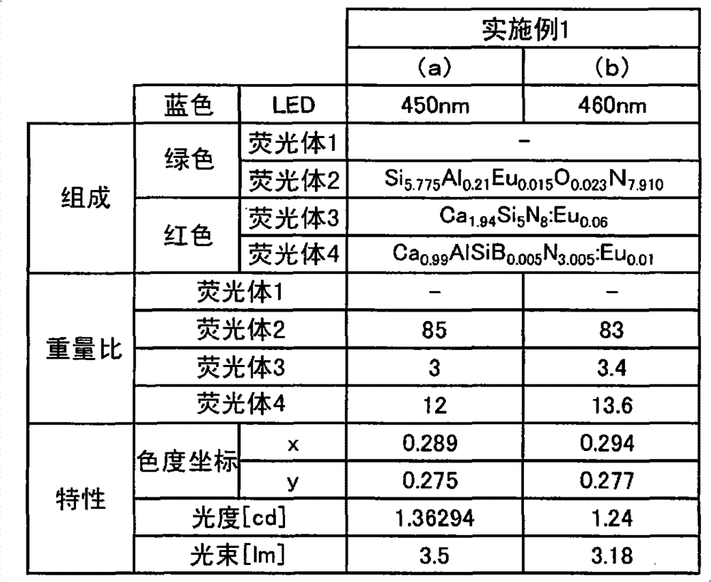
另外,下述表4表示实施例1的各荧光体的真比重a、荧光体的真比重的平均值A、各荧光体的真比重与平均值的差值d(d=a-A)、差值d占平均值A的比例(d/A×100[%])。In addition, the following Table 4 shows the true specific gravity a of each phosphor in Example 1, the average value A of the true specific gravity of the phosphor, the difference d (d=a-A) between the true specific gravity and the average value of each phosphor, and the difference The ratio of d to the average value A (d/A×100[%]).
[表4][Table 4]

(实施例2)(Example 2)
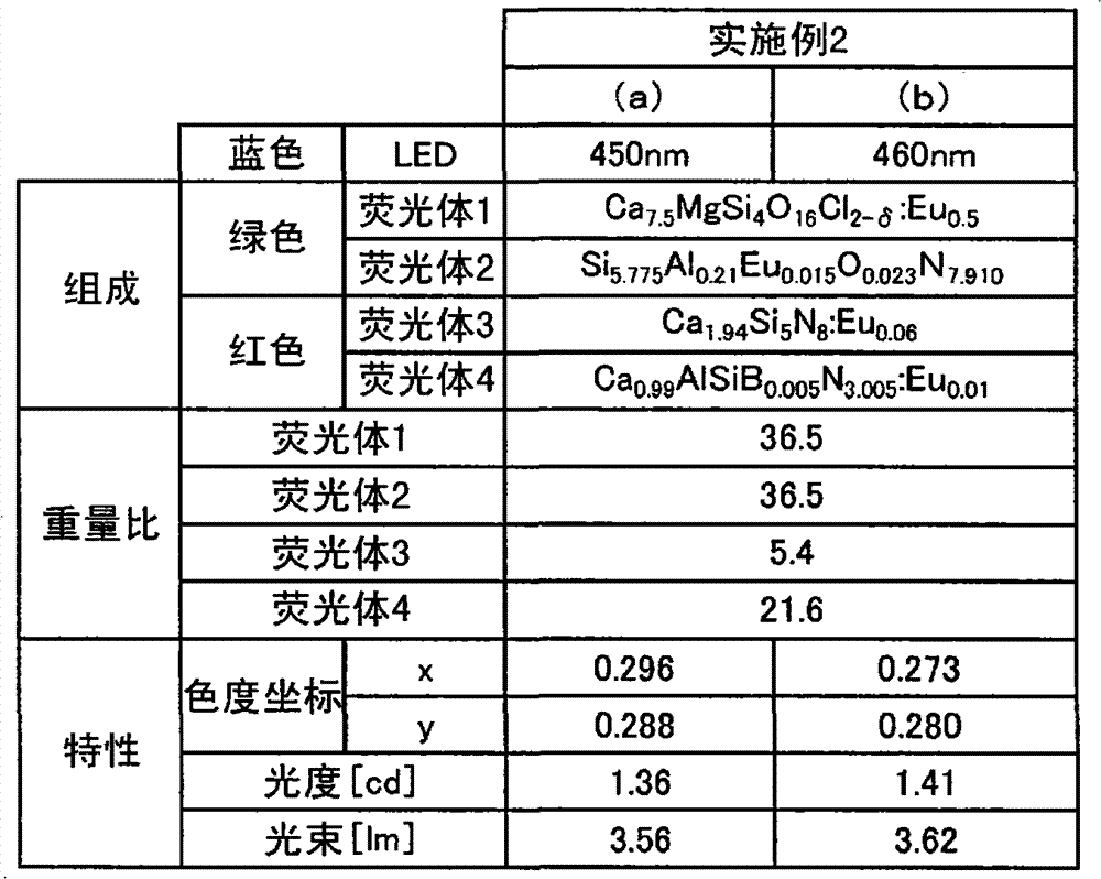
实施例2~7和比较例1所涉及的发光装置除了如下所述地变更了所搭载的荧光体之外,具有与实施例1的发光装置实质上同样的构造。具体而言,实施例2的荧光体是如下所述地、以下列的重量比由两种绿色发光的荧光体、两种红色发光的荧光体构成的。The light-emitting devices according to Examples 2 to 7 and Comparative Example 1 have substantially the same structure as the light-emitting device of Example 1 except that the mounted phosphors are changed as described below. Specifically, the phosphor of Example 2 was composed of two kinds of green-emitting phosphors and two kinds of red-emitting phosphors in the following weight ratios as described below.
绿:Si5.775Al0.21Eu0.015O0.023N7.910+Ca7.5MgSi4O16Cl2-δ:Eu0.5=1+1重量比Green: Si 5.775 Al 0.21 Eu 0.015 O 0.023 N 7.910 +Ca 7.5 MgSi 4 O 16 Cl 2-δ :Eu 0.5 =1+1 weight ratio
红:Ca1.94Si5N8:Eu0.06+Ca0.99AlSiB0.005N3.005:Eu0.01=2+8重量比Red: Ca 1.94 Si 5 N 8 :Eu 0.06 +Ca 0.99 AlSiB 0.005 N 3.005 :Eu 0.01 =2+8 weight ratio
另外,表5记载了各荧光体的组成和重量比、以及发光装置的发光特性。In addition, Table 5 describes the composition and weight ratio of each phosphor, and the light-emitting characteristics of the light-emitting device.
并且,图9表示与实施例2(a)相当的LED450nm激发的发光光谱,图10表示与实施例2(b)相当的LED460nm激发的发光光谱。In addition, FIG. 9 shows the emission spectrum of
[表5][table 5]
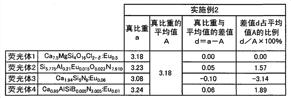
另外,下述表6表示实施例2的各荧光体的真比重a、荧光体的真比重的平均值A、各荧光体的真比重与平均值的差值d(d=a-A)、差值d占平均值A的比例(d/A×100[%])。In addition, the following Table 6 shows the true specific gravity a of each phosphor in Example 2, the average value A of the true specific gravity of the phosphor, the difference d (d=a-A) between the true specific gravity and the average value of each phosphor, and the difference The ratio of d to the average value A (d/A×100[%]).
[表6][Table 6]
(实施例3)(Example 3)
实施例3的荧光体是如下所示地、以下列的重量比由1种绿色发光的荧光体、两种红色发光的荧光体构成的。The phosphor of Example 3 was composed of one green emitting phosphor and two red emitting phosphors in the following weight ratios as shown below.
绿:Ca8MgSi4O16Cl2-δ:EuGreen: Ca 8 MgSi 4 O 16 Cl 2-δ :Eu
红:Ca1.94Si5N8:Eu0.06+Ca0.99AlSiB0.005N3.005:Eu0.01=2+8重量比Red: Ca 1.94 Si 5 N 8 :Eu 0.06 +Ca 0.99 AlSiB 0.005 N 3.005 :Eu 0.01 =2+8 weight ratio
另外,表7表示各荧光体的组成和重量比、以及发光装置的发光特性,图11表示与实施例3(a)相当的LED450nm激发的发光光谱。In addition, Table 7 shows the composition and weight ratio of each phosphor, and the light-emitting characteristics of the light-emitting device, and FIG. 11 shows the light-emitting spectrum of an LED excited at 450 nm corresponding to Example 3(a).
[表7][Table 7]

另外,下述表8表示实施例3的各荧光体的真比重a、荧光体的真比重的平均值A、各荧光体的真比重与平均值的差值d(d=a-A)、差值d占平均值A的比例(d/A×100[%])。In addition, the following Table 8 shows the true specific gravity a of each phosphor in Example 3, the average value A of the true specific gravity of the phosphor, the difference d (d=a-A) between the true specific gravity and the average value of each phosphor, and the difference The ratio of d to the average value A (d/A×100[%]).
[表8][Table 8]

(实施例4)(Example 4)
实施例4的荧光体是如下所示地、以下列的重量比由1种绿色发光的荧光体、两种红色发光的荧光体构成的。The phosphor of Example 4 was composed of one green emitting phosphor and two red emitting phosphors in the following weight ratios as shown below.
绿:Si5.775Al0.21Eu0.015O0.023N7.910 Green: Si 5.775 Al 0.21 Eu 0.015 O 0.023 N 7.910
红:Ca1.94Si5N8:Eu0.06+Ca0.99AlSiB0.005N3.005:Eu0.01=4+6重量比Red: Ca 1.94 Si 5 N 8 :Eu 0.06 +Ca 0.99 AlSiB 0.005 N 3.005 :Eu 0.01 =4+6 weight ratio
另外,表9表示各荧光体的组成和重量比、以及发光装置的发光特性,图12表示与实施例4(a)相当的LED450nm激发的发光光谱。In addition, Table 9 shows the composition and weight ratio of each phosphor, and the light-emitting characteristics of the light-emitting device, and FIG. 12 shows the light-emitting spectrum of an LED excited at 450 nm corresponding to Example 4(a).
[表9][Table 9]

另外,下述表10表示实施例4的各荧光体的真比重a、荧光体的真比重的平均值A、各荧光体的真比重与平均值的差值d(d=a-A)、差值d占平均值A的比例(d/A×100[%])。In addition, the following Table 10 shows the true specific gravity a of each phosphor in Example 4, the average value A of the true specific gravity of the phosphor, the difference d between the true specific gravity and the average value d (d=a-A) of each phosphor, and the difference The ratio of d to the average value A (d/A×100[%]).
[表10][Table 10]

(实施例5)(Example 5)
实施例5的荧光体是如下所示地、以下列的重量比由1种绿色发光的荧光体、1种红色发光的荧光体构成的。The phosphor of Example 5 was composed of one green-emitting phosphor and one red-emitting phosphor in the following weight ratios as shown below.
绿:Ca8MgSi4O16Cl2-δ:EuGreen: Ca 8 MgSi 4 O 16 Cl 2-δ :Eu
红:Ca0.99AlSiN3.005:Eu0.01 Red: Ca 0.99 AlSiN 3.005 : Eu 0.01
另外,表11表示各荧光体的组成和重量比、以及发光装置的发光特性。In addition, Table 11 shows the composition and weight ratio of each phosphor, and the light-emitting characteristics of the light-emitting device.
[表11][Table 11]
另外,下述表12表示实施例5的各荧光体的真比重a、荧光体的真比重的平均值A、各荧光体的真比重与平均值的差值d(d=a-A)、差值d占平均值A的比例(d/A×100[%])。In addition, the following Table 12 shows the true specific gravity a of each phosphor in Example 5, the average value A of the true specific gravity of the phosphor, the difference d (d=a-A) between the true specific gravity and the average value of each phosphor, and the difference The ratio of d to the average value A (d/A×100[%]).
[表12][Table 12]

(实施例6)(Example 6)
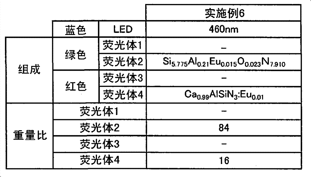
实施例6的荧光体是如下所示地、以下列的重量比由1种绿色发光的荧光体、1种红色发光的荧光体构成的。The phosphor of Example 6 was composed of one green-emitting phosphor and one red-emitting phosphor in the following weight ratios as shown below.
绿:Si5.775Al0.21Eu0.015O0.023N7.910 Green: Si 5.775 Al 0.21 Eu 0.015 O 0.023 N 7.910
红:Ca0.99AlSiN3.005:Eu0.01 Red: Ca 0.99 AlSiN 3.005 : Eu 0.01
另外,表13表示各荧光体的组成及重量比。In addition, Table 13 shows the composition and weight ratio of each phosphor.
[表13][Table 13]
另外,下述表14表示实施例6的各荧光体的真比重a、荧光体的真比重的平均值A、各荧光体的真比重与平均值的差值d(d=a-A)、差值d占平均值A的比例(d/A×100[%])。In addition, the following Table 14 shows the true specific gravity a of each phosphor in Example 6, the average value A of the true specific gravity of the phosphor, the difference d (d=a-A) between the true specific gravity and the average value of each phosphor, and the difference The ratio of d to the average value A (d/A×100[%]).
[表14][Table 14]

(实施例7)(Example 7)
实施例7的荧光体是如下所示地、以下列的重量比由2种绿色发光的荧光体、1种红色发光的荧光体构成的。The phosphor of Example 7 was composed of two green emitting phosphors and one red emitting phosphor in the following weight ratios as shown below.
绿:Si5.775Al0.21Eu0.015O0.023N7.910+Ca7.5MgSi4O16Cl2-δ:Eu0.5=1∶1重量比Green: Si 5.775 Al 0.21 Eu 0.015 O 0.023 N 7.910 +Ca 7.5 MgSi 4 O 16 Cl 2-δ :Eu 0.5 = 1:1 weight ratio
红:Ca0.99AlSiN3.005:Eu0.01 Red: Ca 0.99 AlSiN 3.005 : Eu 0.01
另外,表15表示各荧光体的组成及重量比。In addition, Table 15 shows the composition and weight ratio of each phosphor.
[表15][Table 15]
另外,下述表16表示实施例7的各荧光体的真比重a、荧光体的真比重的平均值A、各荧光体的真比重与平均值的差值d(d=a-A)、差值d占平均值A的比例(d/A×100[%])。In addition, the following Table 16 shows the true specific gravity a of each phosphor in Example 7, the average value A of the true specific gravity of the phosphor, the difference d (d=a-A) between the true specific gravity and the average value of each phosphor, and the difference The ratio of d to the average value A (d/A×100[%]).
[表16][Table 16]
(比较例1)(comparative example 1)
比较例1的荧光体是如下所示地、以下列的重量比由1种绿色发光的荧光体、1种红色发光的荧光体构成的。The phosphor of Comparative Example 1 was composed of one green-emitting phosphor and one red-emitting phosphor in the following weight ratios as shown below.
绿:(Sr0.45Ba0.55)1.93SiO4:Eu0.07 Green: (Sr 0.45 Ba 0.55 ) 1.93 SiO 4 :Eu 0.07
红:Ca0.99AlSiN3.005:Eu0.01 Red: Ca 0.99 AlSiN 3.005 : Eu 0.01
另外,表17表示各荧光体的组成和重量比、以及发光装置的发光特性。In addition, Table 17 shows the composition and weight ratio of each phosphor, and the light-emitting characteristics of the light-emitting device.
[表17][Table 17]
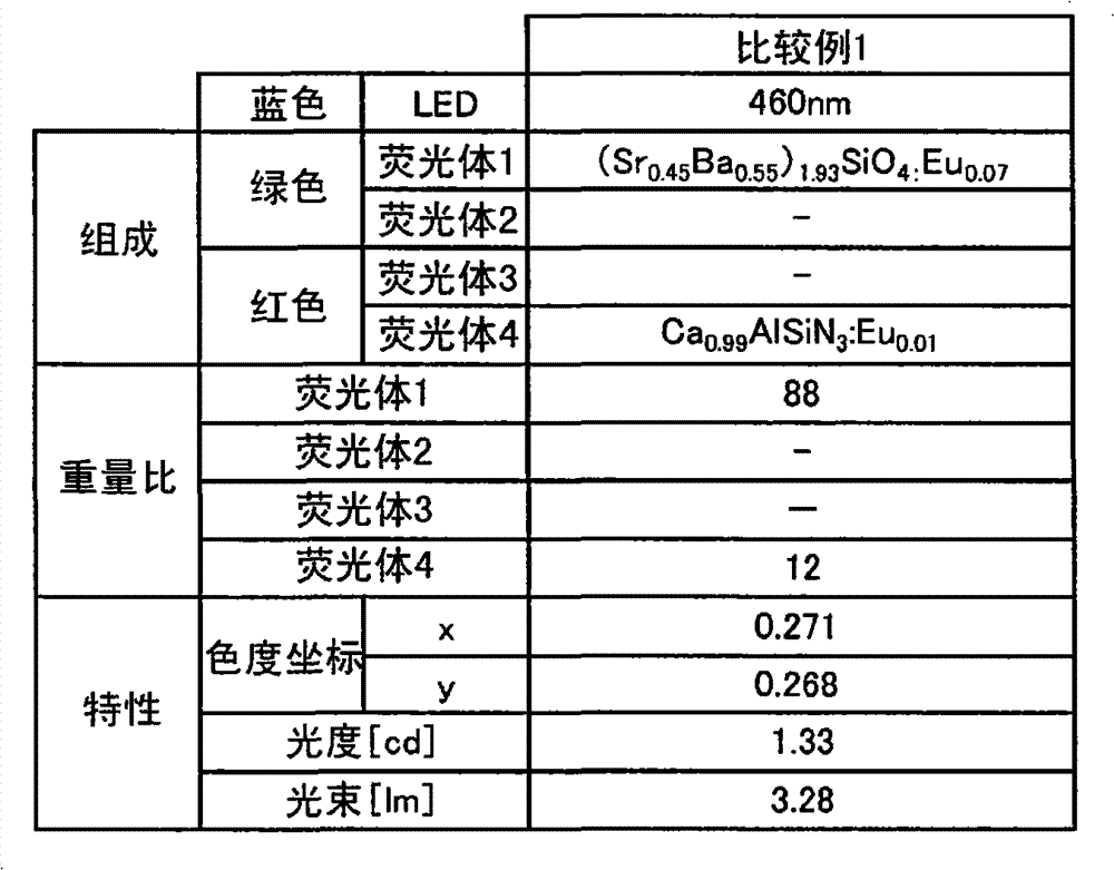
另外,下述表18表示比较例1的各荧光体的真比重a、荧光体的真比重的平均值A、各荧光体的真比重与平均值的差值d(d=a-A)、差值d占平均值A的比例(d/A×100[%])。In addition, the following Table 18 shows the true specific gravity a of each phosphor in Comparative Example 1, the average value A of the true specific gravity of the phosphor, the difference d (d=a-A) between the true specific gravity and the average value of each phosphor, and the difference The ratio of d to the average value A (d/A×100[%]).
[表18][Table 18]
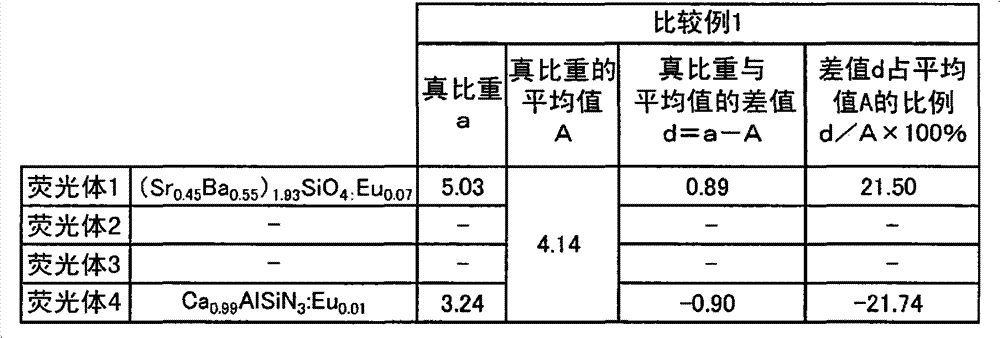
在上述实施例的发光装置中,图13表示发光元件附近的剖视示意图。图13的发光装置表示了被混合的多个荧光体3a、3b、3c大致均匀地分散在发光元件附近而沉降的状态。具体而言,荧光体3a表示绿色荧光体,荧光体3b表示第1红色荧光体,且荧光体3c表示第2红色荧光体。这是将真比重或粒径近似的荧光体混合而得到的效果。即,能够将各荧光体的搭载区域不会偏在而大致均匀地混在一起,因此能够使被来自发光元件2的一次光激发的各二次光有效地扩散。即,能得到颜色不均被极大地减少了的发光。另外,图13的荧光体表示相当于实施例3的荧光体,即Ca8MgSi4O16Cl2-δ:Eu(荧光体3a)、Ca1.94Si5N8:Eu0.06(荧光体3b)、Ca0.99AlSiB0.005N3.005:Eu0.01(荧光体3c)。这些荧光体的真比重的平均值A是3.17,各荧光体的真比重与平均值的差值d占平均值A的比例分别为0.32%、-2.84%、2.21%。In the light-emitting device of the above-mentioned embodiment, FIG. 13 shows a schematic cross-sectional view of the vicinity of the light-emitting element. The light-emitting device in FIG. 13 shows a state in which a plurality of
另一方面,图14表示相当于上述比较例1的发光装置的剖视示意图。即,具有多个荧光体3c、3d,具体而言,是(Sr0.45Ba0.55)1.93SiO4:Eu0.07(荧光体3d)、Ca0.99AlSiN3.005:Eu0.01(荧光体3c)。这些荧光体的真比重的平均值A是4.14,各荧光体的真比重与平均值的差值d占平均值A的比例分别为21.50%、-21.74%。即,不满足d≤|0.16A|的条件。在图14的发光装置中,比重大的荧光体3d沉降在元件附近侧,在其上层叠有荧光体3c。即,各荧光体未大致均匀地扩散而呈层状重叠,其结果是,各成分光未被均匀地混色,来自发光观测面侧的发光产生颜色不均。On the other hand, FIG. 14 shows a schematic cross-sectional view of a light emitting device corresponding to Comparative Example 1 above. That is, there are a plurality of
另外,图8~12表示各实施例发光装置的发光波长。在图的发光波长中,在440nm~470nm处具有第1峰值波长,在510nm~550nm处具有第2峰值波长,在630nm~670nm处具有第3峰值波长。并且,图15是制作10000个以上的上述实施例3b的发光装置、绘制了来自各发光装置的出射光的色度座标的图。同样地,图16是绘制了比较例1的发光装置的色度座标的图。这些图表示绘制的区域越小,则装置间的发光特性差距越少、颜色偏差越少。若比较图15和图16的曲线,在实施例3b的发光装置中,绘图接近而集合在一起,即可知装置间的特性大致统一。因而,利用实施例3b的发光装置,即使是以点光源的集合来再现宽范围区域时,也能实现颜色不均被降低了的面状发光。另一方面,在图16所示的比较例1的发光装置中,装置间的色度差很显著,因此产品的成品率较低。In addition, FIGS. 8 to 12 show the emission wavelengths of the light emitting devices of the respective examples. Among the emission wavelengths in the figure, there is a first peak wavelength at 440nm to 470nm, a second peak wavelength at 510nm to 550nm, and a third peak wavelength at 630nm to 670nm. 15 is a diagram in which more than 10,000 light-emitting devices of the above-mentioned Example 3b were produced, and chromaticity coordinates of light emitted from each light-emitting device were plotted. Similarly, FIG. 16 is a graph plotting chromaticity coordinates of the light-emitting device of Comparative Example 1. FIG. These graphs show that the smaller the plotted area, the smaller the difference in light emission characteristics between devices and the smaller the color deviation. Comparing the curves of FIG. 15 and FIG. 16 , in the light-emitting device of Example 3b, the plots are close to each other, and it can be seen that the characteristics of the devices are substantially uniform. Therefore, with the light emitting device of Example 3b, even when a wide area is reproduced by a collection of point light sources, planar light emission with reduced color unevenness can be realized. On the other hand, in the light-emitting device of Comparative Example 1 shown in FIG. 16 , the difference in chromaticity between devices is significant, so the yield of products is low.
并且,图17表示发光装置的发光光谱,该发光装置由蓝色发光LED和YAG(钇·铝·石榴石)等荧光体构成,其将从该蓝色发光LED发出的光和来自YAG(钇·铝·石榴石)等荧光体的光进行双色混合。用作液晶背光的情况下,从发光装置发出的光通过滤色器而取出蓝色光、绿色光、红色光,从成分光的色度坐标来特定色再现区域,从而求出NTSC比。这次用于求出NTSC比的彩色滤光器是使用了YAG:Ce的发光装置的NTSC比为70%左右的通常的滤光器。图18、图19表示图17所示的双色混合的发光装置的NTSC比。但是,图18是LED450nm激发的发光装置的NTSC比,图19是LED460nm激发的发光装置的NTSC比。具体而言,在图18、图19中,NTSC比分别是72.4%、72.9%。And, Fig. 17 shows the emission spectrum of a light-emitting device, which is composed of a blue light-emitting LED and phosphors such as YAG (yttrium aluminum garnet), which combines the light emitted from the blue light-emitting LED with the light from YAG (yttrium aluminum garnet).・Aluminum・Garnet) and other phosphor light are mixed in two colors. When used as a liquid crystal backlight, the light emitted from the light emitting device passes through a color filter to extract blue light, green light, and red light, and the color reproduction area is specified from the chromaticity coordinates of the component light to obtain the NTSC ratio. The color filter used for calculating the NTSC ratio this time is a normal filter in which the NTSC ratio of the light-emitting device using YAG:Ce is about 70%. 18 and 19 show the NTSC ratio of the two-color mixed light-emitting device shown in FIG. 17 . However, FIG. 18 shows the NTSC ratio of a light-emitting device excited by LED at 450 nm, and FIG. 19 shows the NTSC ratio of a light-emitting device excited by LED at 460 nm. Specifically, in FIG. 18 and FIG. 19 , the NTSC ratios are 72.4% and 72.9%, respectively.
并且,图20~图23表示搭载了在450nm处具有峰值波长的LED的实施例1~4的发光装置(实施例1(a)、实施例2(a)、实施例3(a)、实施例4(a))的发光特性的NTSC比。另外,在图20~图23中,用EXPL1a、EXPL2a、EXPL3a、EXPL4a分别表示各发光装置的色度图。同样地图24~图27表示搭载了在460nm处具有峰值波长的LED的发光装置(实施例1(b)、实施例2(b)、实施例3(b)、实施例4(b))的NTSC比。另外,在图24~图27中将各发光装置的色度图分别表示为EXPL1b、EXPL2b、EXPL3b、EXPL4b。可知从发光装置发出的光如图20~图27所示地在发光特性方面满足NTSC比(x、y)的78.7~83.6%,具有颜色再现优异的发光特性。即,实施例的发光装置用作监视器、数码相机、打印机等的背光的情况下,能够较深地且鲜明地再现各装置的RGB的各颜色。20 to 23 show light-emitting devices of Examples 1 to 4 (Example 1(a), Example 2(a), Example 3(a), Example NTSC ratio of luminescence characteristics of Example 4(a)). In addition, in FIGS. 20 to 23 , the chromaticity diagrams of the respective light-emitting devices are represented by EXPL1a, EXPL2a, EXPL3a, and EXPL4a, respectively. Similarly, maps 24 to 27 show light-emitting devices (Example 1(b), Example 2(b), Example 3(b), Example 4(b)) equipped with LEDs having a peak wavelength at 460 nm. NTSC vs. In addition, in FIGS. 24 to 27 , the chromaticity diagrams of the respective light-emitting devices are represented as EXPL1b, EXPL2b, EXPL3b, and EXPL4b, respectively. It can be seen that the light emitted from the light emitting device satisfies 78.7 to 83.6% of the NTSC ratio (x, y) in light emission characteristics as shown in FIGS. 20 to 27 , and has light emission characteristics excellent in color reproduction. That is, when the light-emitting device of the embodiment is used as a backlight of a monitor, a digital camera, a printer, etc., each color of RGB of each device can be reproduced deeply and vividly.
另外,下述表19表示上述双色混合型的发光装置的NTSC比的数值和三波长型的发光装置的NTSC比的数值。In addition, the following Table 19 shows the numerical value of the NTSC ratio of the above-mentioned two-color mixing type light-emitting device and the numerical value of the NTSC ratio of the three-wavelength type light-emitting device.
[表19][Table 19]

如表19所示,可知与双色混合型的发光装置相比,实施例所涉及的发光装置的NTSC比(参照图20~图27)被改善了大约5~10%。As shown in Table 19, it can be seen that the NTSC ratio (see FIGS. 20 to 27 ) of the light emitting device according to the example is improved by about 5 to 10% compared with the two-color mixed light emitting device.
(实施例8~12)(Embodiments 8-12)
另外,作为实施例8,作为能够用于本发明的发光装置的两种以上的绿色发光荧光体,混合了在522nm处具有峰值波长的Ca7.5MgSi4O16Cl2-δ:Eu0.5和在540nm处具有峰值波长的Si5.775Al0.21Eu0.015O0.023N7.910。该绿色发光荧光体中的Si5.775Al0.21Eu0.015O0.023N7.910的含有量为30wt%。另外,实施例9~12是将实施例8中的Si5.775Al0.21Eu0.015O0.023N7.910的含有量分别设定为40wt%、50wt%、60wt%、70wt%。通过使在上述范围内含有Si5.775Al0.21Eu0.015O0.023N7.910,能够在529nm~535nm的范围内具有由两种绿色发光荧光体形成的峰值波长。实施例8~12的峰值波长是通过利用发出460nm的光的发光元件对两种绿色发光荧光体进行激发而测量的。将测量结果与色度座标、半值幅、亮度一起表示在下述表20中。表20中的亮度是用发出460nm的光的发光元件激发时的Y3Al5O12:Ce的亮度作为100%来计算的。另外,图32表示实施例8~12所涉及的发光光谱图。另外,在图32中,用EXPL8、EXPL9、EXPL10、EXPL11、EXPL12分别表示实施例8~实施例12的460nm激发的各发光光谱。In addition, as Example 8, Ca 7.5 MgSi 4 O 16 Cl 2-δ :Eu 0.5 having a peak wavelength at 522 nm and Ca 7.5 MgSi 4 O 16 Cl 2-δ :Eu 0.5 that can be used in the light-emitting device of the present invention were mixed as two or more green light-emitting phosphors that can be used in the light-emitting device of the present invention. Si 5.775 Al 0.21 Eu 0.015 O 0.023 N 7.910 with a peak wavelength at 540 nm. The content of Si 5.775 Al 0.21 Eu 0.015 O 0.023 N 7.910 in the green light-emitting phosphor was 30 wt %. In Examples 9 to 12, the contents of Si 5.775 Al 0.21 Eu 0.015 O 0.023 N 7.910 in Example 8 were set to 40 wt %, 50 wt %, 60 wt %, and 70 wt %, respectively. By containing Si 5.775 Al 0.21 Eu 0.015 O 0.023 N 7.910 in the above-mentioned range, it is possible to have peak wavelengths formed by two kinds of green light-emitting phosphors in the range of 529 nm to 535 nm. The peak wavelengths of Examples 8 to 12 were measured by exciting the two green light-emitting phosphors with a light-emitting element emitting light at 460 nm. The measurement results are shown in Table 20 below together with chromaticity coordinates, half-value width, and luminance. The luminances in Table 20 were calculated using the luminance of Y 3 Al 5 O 12 :Ce when excited by a light-emitting element emitting light of 460 nm as 100%. In addition, FIG. 32 shows emission spectrum diagrams related to Examples 8-12. In addition, in FIG. 32 , each emission spectrum excited at 460 nm in Examples 8 to 12 is represented by EXPL8, EXPL9, EXPL10, EXPL11, and EXPL12, respectively.
[表20][Table 20]
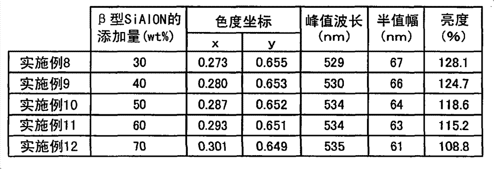
如表20所示,实施例8~12的亮度都是100%以上的高亮度。这样,通过混合两种绿色发光荧光体,能够得到高亮度而且在529nm~535nm的范围内具有峰值波长的绿色发光荧光体。As shown in Table 20, the luminances of Examples 8 to 12 were all high luminances of 100% or more. In this way, by mixing two kinds of green light emitting phosphors, it is possible to obtain a green light emitting phosphor with high luminance and a peak wavelength in the range of 529 nm to 535 nm.
(比较例2~3)(Comparative examples 2 to 3)
比较例2是由Ca7.2MgSi4O16Cl2-δ:Eu0.8单独构成的绿色发光荧光体。比较例3是由Ca7.1MgSi4O16Cl2-δ:Eu0.9单独构成的绿色发光荧光体。比较例2和3是通过增加实施例8~12所使用的Ca7.2MgSi4O16Cl2-δ:Eu0.5中的Eu量而使峰值波长从522nm长波长化而成的。作为本发明所涉及的卤素氧化物荧光体的优选方式的Ca7.5MgSi4O16Cl2-δ:Eu0.5,在为了变更峰值波长而调整荧光体的组成时,存在亮度显著降低的倾向。Comparative Example 2 is a green light-emitting phosphor composed of Ca 7.2 MgSi 4 O 16 Cl 2-δ :Eu 0.8 alone. Comparative Example 3 is a green light-emitting phosphor composed of Ca 7.1 MgSi 4 O 16 Cl 2-δ :Eu 0.9 alone. In Comparative Examples 2 and 3, the peak wavelength was increased from 522 nm by increasing the amount of Eu in Ca 7.2 MgSi 4 O 16 Cl 2-δ :Eu 0.5 used in Examples 8 to 12. Ca 7.5 MgSi 4 O 16 Cl 2-δ :Eu 0.5 , which is a preferred embodiment of the halogen oxide phosphor according to the present invention, tends to significantly lower the luminance when the composition of the phosphor is adjusted to change the peak wavelength.
(比较例4~5)(Comparative Examples 4-5)
另外,比较例4是由Si5.92Al0.07Eu0.01O0.015N7.96单独构成的绿色发光荧光体。比较例5是由Si5.88Al0.11Eu0.01O0.015N7.95单独构成的绿色发光荧光体。比较例4和5是通过调整实施例8~12所使用Si5.775Al0.21Eu0.015O0.023N7.910的组成比,使峰值波长从540nm短波长化而成的。作为本发明所涉及的β型SiAlON荧光体优选方式的Si5.775Al0.21Eu0.015O0.023N7.910,在为了变更峰值波长而调整荧光体的组成时,存在亮度显著降低的倾向。In addition, Comparative Example 4 is a green light-emitting phosphor composed of Si 5.92 Al 0.07 Eu 0.01 O 0.015 N 7.96 alone. Comparative Example 5 is a green light-emitting phosphor composed of Si 5.88 Al 0.11 Eu 0.01 O 0.015 N 7.95 alone. Comparative Examples 4 and 5 were obtained by adjusting the composition ratio of Si 5.775 Al 0.21 Eu 0.015 O 0.023 N 7.910 used in Examples 8 to 12 to shorten the peak wavelength from 540 nm. Si 5.775 Al 0.21 Eu 0.015 O 0.023 N 7.910 , which is a preferred embodiment of the β-type SiAlON phosphor according to the present invention, tends to significantly lower the luminance when the composition of the phosphor is adjusted to change the peak wavelength.
比较例2~5的峰值波长是利用发出460nm的光的发光元件,对比较例2~5的绿色发光荧光体进行激发而测量的。将测量结果与分子式、色度座标、亮度一起表示在下述表21中。表21中的亮度是用发出460nm的光的发光元件激发时的Y3Al5O12:Ce的亮度作为100%来计算的。The peak wavelengths of Comparative Examples 2 to 5 were measured by exciting the green light-emitting phosphors of Comparative Examples 2 to 5 with a light-emitting element emitting light of 460 nm. The measurement results are shown in Table 21 below together with the molecular formula, chromaticity coordinates, and brightness. The luminances in Table 21 were calculated using the luminance of Y 3 Al 5 O 12 :Ce when excited by a light-emitting element emitting light of 460 nm as 100%.
[表21][Table 21]

如表21所示,比较例2在529nm处具有峰值波长。不过,相对于同样在529nm处具有峰值波长的实施例8,比较例2的亮度显著降低。另外,比较例3和4在530nm处具有峰值波长,但相对于同样在530nm处具有峰值波长的实施例9,亮度显著降低。并且,比较例5在535nm处具有峰值波长,但相对于具有相同的峰值波长的实施例12,亮度显著降低。另外,在实施例8~12和比较例2~5中,即使是具有相同的峰值波长的发光光谱,半值幅等也互不相同,则色度座标也未必相同。这是因为色度座标依存于发光光谱的形状的缘故。不过,若能量最高的峰值波长相同,则发光颜色接近相同颜色。As shown in Table 21, Comparative Example 2 has a peak wavelength at 529 nm. However, compared to Example 8, which also has a peak wavelength at 529 nm, the luminance of Comparative Example 2 is significantly lowered. In addition, Comparative Examples 3 and 4 had a peak wavelength at 530 nm, but the luminance was significantly lower than that of Example 9, which also had a peak wavelength at 530 nm. Also, Comparative Example 5 had a peak wavelength at 535 nm, but the luminance was remarkably lower than that of Example 12 having the same peak wavelength. In addition, in Examples 8 to 12 and Comparative Examples 2 to 5, even though the emission spectra having the same peak wavelength have different half-value widths, the chromaticity coordinates are not necessarily the same. This is because the chromaticity coordinates depend on the shape of the emission spectrum. However, if the peak wavelengths with the highest energy are the same, the emission colors will be close to the same color.
另外,在上述实施例的发光装置中,绿色发光荧光体的重量为荧光体的总重量的60%~95%;或/和红色发光荧光体的重量比为荧光体的总重量的5%~40%。In addition, in the light-emitting device of the above-mentioned embodiment, the weight of the green light-emitting phosphor is 60% to 95% of the total weight of the phosphor; or/and the weight ratio of the red light-emitting phosphor is 5% to 5% of the total weight of the phosphor. 40%.
换句话说,实施方式1的发光装置通过将构成一个色相的多个荧光体的分配比率设定为各种情况,能够调整色相的波长区域。进而,能控制发光装置的发出光的颜色再现。其结果是,形成能够发出与发光装置的最终利用形态相对应的发光波长的装置。例如,在只透过规定波长的滤色器中,能够实现高效率地发射出与有效波长区域相当的波长的成分光,因此能够自然且致密地表现影像。或者,与因投入电力的偏差等产生的发光元件的波长区域的变化相对应,以便能调节绿色、红色的发光波长。另外,即使在可能成为亮度降低的主要原因的波长区域中,也使能见度高的波长干涉,从而能维持亮度和色度这两方面的特性。即,能根据特性灵活地变更并控制构成白色光的成分光的比率,因此与重新变更组成比来制造荧光体的情况相比,能容易地得到规定的发光波长区域。In other words, the light-emitting device according to
(实施方式2)(Embodiment 2)
图28(a)表示本发明的实施方式2所涉及的发光装置40的立体图。图28(b)是图28(a)所示的半导体发光装置40沿XXVIIIB-XXVIIIB’线的剖视图。下面根据图28(a)、(b)说明实施方式4的发光装置40的概况。发光装置40在引线框4上安装有组件12,该组件12具备朝着上部呈大致凹形状开口的空间。并且,在该组件12的空间内且在露出的引线框4上安装有多个发光元件2。也就是说,组件12成为包围发光元件2的框体。另外,在组件12的开口空间内也载置有齐纳二极管等施加有规定电压以上的电压时处于通电状态的保护元件13。并且,发光元件2借助接合线5或凸块(bump)等与引线框4电连接。另外,组件12的开口的空间部被密封树脂6填充。FIG. 28( a ) shows a perspective view of a
图28(b)表示组件12内所含有的荧光体3。(省略了图28(a)的荧光体3)。该荧光体3能使用上述的荧光体,树脂6内的荧光体的含有状态与实施方式1相同。FIG. 28( b ) shows the
(实施方式3)(Embodiment 3)
图29表示实施方式3所涉及的炮弹型的发光装置1。该发光装置1具有:载置于用由导电性的部件构成的引线框4成型而成的凹形状的杯状件10内且载置在引线框4上的发光元件2;将从该发光元件2发出的光的至少一部分进行波长转换的荧光体3。该荧光体3能够搭载实施方式1的荧光体的情况与实施方式2相同。另外,发光元件2使用在大约360nm~480nm、优选在445nm~470nm处具有发光峰值波长的发光元件。形成于发光元件2的正负电极9借助导电性的接合线5与引线框4电连接。另外,作为引线框4的一部分的引线框电极4a突出,发光元件2、引线框4和接合线5被炮弹形状的模制件11覆盖。在模制件11内填充有透光性的树脂6,而且树脂6含有荧光体3。树脂6优选使用在分子内具有硅氧烷键的硅系树脂、硅氧烷骨架的氟树脂等硅树脂组合物。由此,能形成耐光性和耐热性优异的密封树脂。另外,树脂6也可以使用环氧树脂组合物、丙烯酸树脂组合物等具有透光性的绝缘树脂组合物。通过从外部电源对从该树脂6突出的引线框电极4a供给电力,使得从发光元件2的层内所含有的发光层8发出光。从该发光层8输出的发光峰值波长具有从紫外区域到蓝色区域的500nm以下附近的发光光谱。该被发出的光的一部分对荧光体3进行激发,能够得到具有与来自发光层8的主光源的波长不同的波长的光。FIG. 29 shows a cannonball-shaped
(实施方式4)(Embodiment 4)
接着,图30表示本发明的实施方式4所涉及的发光装置20。该发光装置20对与实施方式3所涉及的发光装置1的部件相同的部件标注相同的附图标记,省略其说明。该发光装置20只在用引线框4成型而成的凹形状的杯状件10内填充有包含上述荧光体3的树脂6。在模制件11内且在填充到杯状件10的外部的树脂6内不含有荧光体3。优选含有荧光体3的树脂与不含有荧光体3的树脂的种类相同,但即使不同也没有关系。若是不同种类的树脂,也能够利用各树脂硬化所需的温度差使软度变化。Next, FIG. 30 shows a
发光装置20在形成杯状件10内的开口部的底面的大致中央部载置有发光元件2,因此发光元件2被埋设在含有荧光体3的树脂6内。为了使来自发光层8的光均匀且利用荧光体3进行波长转换,使来自发光元件的光均匀地通过含有荧光体的树脂即可。也就是说,使来自发光层8的光所通过的含有荧光体的树脂膜的厚度均匀即可。因而,从发光元件2的周围到杯状件10的壁面和上部的距离一致地确定杯状件10的大小和发光元件2的载置位置即可。只要是该发光装置20,就容易均匀地调整含有荧光体3的树脂6的膜厚。In the
(实施方式5)(Embodiment 5)
并且,作为本发明的实施方式5所涉及的发光装置,图31表示罩型发光装置30。发光装置30是通过在实施方式2的发光装置20的模制件11表面罩上罩31而构成的,该罩31由分散有荧光体3的透光性树脂构成。Furthermore, FIG. 31 shows a cover-type
罩31是使荧光体3a均匀地分散到透光性的树脂6a中而形成的。将含有该荧光体3a的树脂6a成型为与发光装置30的模制件11的外表面形状嵌合的形状。或者,也可以是如下所述的制造方法:在规定的模架内放入了含有荧光体的透光性的树脂6a之后,将发光装置30压入到该模架内来进行成型。作为罩31的树脂6a的具体的材料,能够采用环氧树脂、尿素树脂、硅树脂等温度特性、耐气候性优异的透明树脂、以及硅胶、玻璃、无机粘结剂等。除了上述之外,能使用三聚氰胺树脂、酚醛树脂等热固性树脂。另外,也能够使用聚乙烯、聚丙烯、聚氯乙烯、聚苯乙烯等热塑性树脂、以及苯乙烯-丁二烯嵌段共聚物、嵌段聚氨脂等热塑性橡胶等。另外,也可以与荧光体一起含有扩散剂、钛酸钡、氧化钛、氧化铝等。另外,也可以含有光稳定剂和着色剂。罩31所使用的荧光体3a不仅可以利用一种荧光体,也可以利用混合了多个荧光体而成的荧光体、层叠成层状的荧光体。The
在发光装置30中,能够只使罩31内的树脂6a含有荧光体3a,但除此之外,也可以在杯状件10内也填充含有荧光体3的树脂6。荧光体3、3a的种类既可以相同也可以不同,另外,也能在各树脂6、6a内含有多个荧光体。由此,能实现各种发光颜色。作为一个例子,列举出发出白色光的发光装置。从发光元件2发出的光对荧光体3进行激发,而发出从深绿色到绿色以及从黄色到红色的光。从该荧光体3发出的光的一部分对罩31的荧光体3a进行激发,发出从绿色到黄色系区域的光。利用这些荧光体的混色光,从罩31的表面向外发出白色系的光。另外,所搭载的各种荧光体与实施方式1相同。In the
本发明的发光装置优选用于荧光显示管、显示器、PDP、CRT、FL、FED以及投射管等,特别是用于以蓝色发光二极管或紫外线发光二极管作为光源的发光特性极为优异的白色的照明用光源、LED显示器、背光光源、信号机、照明式开关、各种传感器和各种指示器等。另外,能用作期望能够较深地且鲜明地再现RGB的各颜色的监视器、数码相机、打印机等的背光用的发光装置。The light-emitting device of the present invention is preferably used in fluorescent display tubes, displays, PDPs, CRTs, FLs, FEDs, and projection tubes, etc., especially for white lighting that uses blue light-emitting diodes or ultraviolet light-emitting diodes as a light source with excellent light-emitting characteristics. Light source, LED display, backlight source, signal machine, illuminated switch, various sensors and various indicators, etc. In addition, it can be used as a light-emitting device for backlights of monitors, digital cameras, printers, and the like that are expected to reproduce RGB colors deeply and vividly.
Claims (10)
Applications Claiming Priority (3)
| Application Number | Priority Date | Filing Date | Title |
|---|---|---|---|
| JP2008010157 | 2008-01-21 | ||
| JP2008-010157 | 2008-01-21 | ||
| PCT/JP2009/000159 WO2009093427A1 (en) | 2008-01-21 | 2009-01-16 | Light emitting device |
Publications (2)
| Publication Number | Publication Date |
|---|---|
| CN101925665A CN101925665A (en) | 2010-12-22 |
| CN101925665B true CN101925665B (en) | 2013-04-03 |
Family
ID=40900939
Family Applications (1)
| Application Number | Title | Priority Date | Filing Date |
|---|---|---|---|
| CN2009801026966A Active CN101925665B (en) | 2008-01-21 | 2009-01-16 | Light emitting device |
Country Status (5)
| Country | Link |
|---|---|
| US (1) | US8040041B2 (en) |
| EP (1) | EP2246409B1 (en) |
| JP (1) | JP5644112B2 (en) |
| CN (1) | CN101925665B (en) |
| WO (1) | WO2009093427A1 (en) |
Families Citing this family (63)
| Publication number | Priority date | Publication date | Assignee | Title |
|---|---|---|---|---|
| US8274215B2 (en) * | 2008-12-15 | 2012-09-25 | Intematix Corporation | Nitride-based, red-emitting phosphors |
| KR101134815B1 (en) * | 2010-01-15 | 2012-04-13 | 엘지이노텍 주식회사 | Display device and manufacturing method of the same |
| JP2011171590A (en) * | 2010-02-19 | 2011-09-01 | Citizen Electronics Co Ltd | Light emitting diode |
| JP2011181793A (en) * | 2010-03-03 | 2011-09-15 | Koito Mfg Co Ltd | Light emitting device |
| WO2012043567A1 (en) * | 2010-09-28 | 2012-04-05 | 三菱化学株式会社 | Phosphor and light-emitting device using same |
| CN102986044B (en) * | 2010-10-15 | 2015-05-06 | 三菱化学株式会社 | White light-emitting devices and lighting fixtures |
| JP5864851B2 (en) * | 2010-12-09 | 2016-02-17 | シャープ株式会社 | Light emitting device |
| KR101781437B1 (en) * | 2011-04-29 | 2017-09-25 | 삼성전자주식회사 | White light emitting device, display apparatus and illumination apparatus |
| CN105762257A (en) * | 2011-08-02 | 2016-07-13 | 亿光电子(中国)有限公司 | Phosphor composition and white light emitting device composed of phosphor |
| CN105932141A (en) * | 2011-08-02 | 2016-09-07 | 亿光电子(中国)有限公司 | Fluorescent powder component and white light-emitting device employing same |
| TWI464241B (en) | 2011-08-02 | 2014-12-11 | 億光電子工業股份有限公司 | Fluorescent powder composition and white light-emitting device using the same |
| US8951441B2 (en) | 2011-12-30 | 2015-02-10 | Intematix Corporation | Nitride phosphors with interstitial cations for charge balance |
| US8663502B2 (en) | 2011-12-30 | 2014-03-04 | Intematix Corporation | Red-emitting nitride-based phosphors |
| JP2013163736A (en) * | 2012-02-09 | 2013-08-22 | Denki Kagaku Kogyo Kk | Phosphor and light-emitting device |
| JP2013163722A (en) * | 2012-02-09 | 2013-08-22 | Denki Kagaku Kogyo Kk | Phosphor and light-emitting device |
| JP2013163723A (en) * | 2012-02-09 | 2013-08-22 | Denki Kagaku Kogyo Kk | Phosphor and light-emitting device |
| JP5886070B2 (en) * | 2012-02-09 | 2016-03-16 | デンカ株式会社 | Phosphor and light emitting device |
| JP5919015B2 (en) * | 2012-02-09 | 2016-05-18 | デンカ株式会社 | Phosphor and light emitting device |
| JP5697766B2 (en) * | 2012-02-09 | 2015-04-08 | 電気化学工業株式会社 | Phosphor and light emitting device |
| JP5945867B2 (en) * | 2012-05-11 | 2016-07-05 | パナソニックIpマネジメント株式会社 | Lighting device |
| US8597545B1 (en) | 2012-07-18 | 2013-12-03 | Intematix Corporation | Red-emitting nitride-based calcium-stabilized phosphors |
| KR20150082426A (en) * | 2012-11-01 | 2015-07-15 | 코닌클리케 필립스 엔.브이. | Led-based device with wide color gamut |
| TWI464238B (en) * | 2013-03-27 | 2014-12-11 | 奇美實業股份有限公司 | Phosphor and illuminating device |
| DE102013217055B4 (en) | 2013-05-17 | 2022-08-25 | Tridonic Gmbh & Co Kg | White light LED module for object lighting |
| JP6291735B2 (en) * | 2013-07-05 | 2018-03-14 | 日亜化学工業株式会社 | Light emitting device |
| KR101429095B1 (en) * | 2013-07-09 | 2014-08-12 | 피에스아이 주식회사 | LED lamps with nano-scale LED electrode assembly |
| JP6236999B2 (en) | 2013-08-29 | 2017-11-29 | 日亜化学工業株式会社 | Light emitting device |
| JP6380826B2 (en) * | 2013-09-20 | 2018-08-29 | パナソニックIpマネジメント株式会社 | Light source device |
| CN108305929B (en) | 2013-10-02 | 2021-02-05 | Glbtech株式会社 | White light-emitting device with high color rendering |
| JP6209949B2 (en) * | 2013-11-13 | 2017-10-11 | 日亜化学工業株式会社 | LIGHT EMITTING DEVICE AND LIGHT EMITTING DEVICE MANUFACTURING METHOD |
| DE112015001628B4 (en) * | 2014-04-02 | 2021-07-22 | Denka Company Limited | Hydrophobic phosphor and light emitting device |
| JP6156440B2 (en) * | 2014-05-30 | 2017-07-05 | 日亜化学工業株式会社 | Red light emitting phosphor and light emitting device using the same |
| KR101809793B1 (en) * | 2014-09-30 | 2017-12-15 | 니치아 카가쿠 고교 가부시키가이샤 | Fluoride fluorescent material, method for producing the same, and light emitting device |
| KR102310038B1 (en) * | 2015-01-16 | 2021-10-08 | 서울반도체 주식회사 | White light emitting device |
| KR102323694B1 (en) * | 2015-01-20 | 2021-11-11 | 서울반도체 주식회사 | White light emitting device |
| US10424562B2 (en) * | 2014-12-16 | 2019-09-24 | Citizen Electronics Co., Ltd. | Light emitting device with phosphors |
| KR102357584B1 (en) | 2014-12-17 | 2022-02-04 | 삼성전자주식회사 | Nitride phosphor, light emitting device, display apparatus and illumination apparatus |
| JP6550889B2 (en) * | 2015-04-22 | 2019-07-31 | 日亜化学工業株式会社 | Light emitting device and manufacturing method thereof |
| KR102423748B1 (en) * | 2015-07-08 | 2022-07-22 | 쑤저우 레킨 세미컨덕터 컴퍼니 리미티드 | Lgiht emitting device |
| KR102432030B1 (en) * | 2015-08-25 | 2022-08-12 | 쑤저우 레킨 세미컨덕터 컴퍼니 리미티드 | Lgiht emitting device |
| DE102016104369A1 (en) * | 2016-03-10 | 2017-09-14 | Osram Opto Semiconductors Gmbh | Phosphor mixture and optoelectronic component with a phosphor mixture |
| JP6233668B2 (en) * | 2016-06-01 | 2017-11-22 | パナソニックIpマネジメント株式会社 | Light source device |
| US10604701B2 (en) * | 2016-09-29 | 2020-03-31 | Nichia Corporation | Method of producing nitride fluorescent material, and nitride fluorescent material |
| JP6669147B2 (en) * | 2016-10-31 | 2020-03-18 | 日亜化学工業株式会社 | Light emitting device |
| JP2020109850A (en) * | 2016-10-31 | 2020-07-16 | 日亜化学工業株式会社 | Method for manufacturing light emitting device |
| US10243124B2 (en) * | 2016-12-26 | 2019-03-26 | Nichia Corporation | Light emitting device |
| JP6558378B2 (en) * | 2017-01-13 | 2019-08-14 | 日亜化学工業株式会社 | Light emitting device |
| JP6923816B2 (en) * | 2017-01-13 | 2021-08-25 | 日亜化学工業株式会社 | Light emitting device |
| US10270015B1 (en) | 2017-01-13 | 2019-04-23 | Nichia Corporation | Light-emitting device |
| TWI848915B (en) * | 2017-07-28 | 2024-07-21 | 日商杜邦東麗特殊材料股份有限公司 | Resin sheet for optical component, optical component, laminate or light-emitting element having the same, and method for producing resin sheet for optical component |
| US10056530B1 (en) * | 2017-07-31 | 2018-08-21 | Eie Materials, Inc. | Phosphor-converted white light emitting diodes having narrow-band green phosphors |
| JP6670804B2 (en) * | 2017-08-02 | 2020-03-25 | シャープ株式会社 | Light emitting device and image display device |
| US10193042B1 (en) * | 2017-12-27 | 2019-01-29 | Innolux Corporation | Display device |
| TWI648878B (en) * | 2018-05-15 | 2019-01-21 | 東貝光電科技股份有限公司 | LED light source, LED light source manufacturing method and direct type display thereof |
| JP7303437B2 (en) * | 2018-09-28 | 2023-07-05 | 日亜化学工業株式会社 | Light-emitting device and lamp equipped with the same |
| JP7299492B2 (en) * | 2018-10-15 | 2023-06-28 | 日亜化学工業株式会社 | Light-emitting device and light-emitting module |
| JP7224983B2 (en) * | 2019-03-19 | 2023-02-20 | スタンレー電気株式会社 | Semiconductor light-emitting device and semiconductor light-emitting module |
| CN113994413B (en) * | 2019-06-25 | 2023-08-01 | 夏普株式会社 | Display device and image processing method |
| US12510214B2 (en) | 2020-01-14 | 2025-12-30 | Lg Electronics Inc. | Lighting apparatus and method for manufacturing same |
| TWI728873B (en) | 2020-07-21 | 2021-05-21 | 隆達電子股份有限公司 | Light-emitting diode device |
| US11294238B1 (en) | 2020-10-29 | 2022-04-05 | Lextar Electronics Corporation | Low blue light backlight module |
| JP2024052303A (en) * | 2022-09-30 | 2024-04-11 | 日亜化学工業株式会社 | Light-emitting device |
| JP2024168948A (en) * | 2023-05-25 | 2024-12-05 | パナソニックIpマネジメント株式会社 | LED module and lighting fixture |
Citations (2)
| Publication number | Priority date | Publication date | Assignee | Title |
|---|---|---|---|---|
| JP2007262417A (en) * | 2007-05-18 | 2007-10-11 | National Institute For Materials Science | Phosphor |
| WO2007135975A1 (en) * | 2006-05-19 | 2007-11-29 | Mitsubishi Chemical Corporation | Nitrogen-containing alloy and method for producing phosphor by using the same |
Family Cites Families (22)
| Publication number | Priority date | Publication date | Assignee | Title |
|---|---|---|---|---|
| CA2380444A1 (en) | 2000-05-29 | 2001-12-06 | Patent-Treuhand-Gesellschaft Fuer Elektrische Gluehlampen Mbh | Led-based white-emitting illumination unit |
| DE10026435A1 (en) * | 2000-05-29 | 2002-04-18 | Osram Opto Semiconductors Gmbh | Calcium-magnesium-chlorosilicate phosphor and its application in luminescence conversion LEDs |
| JP2003037295A (en) * | 2001-07-05 | 2003-02-07 | Taiwan Lite On Electronics Inc | Light-emitting diode and manufacturing method therefor |
| DE10133352A1 (en) * | 2001-07-16 | 2003-02-06 | Patent Treuhand Ges Fuer Elektrische Gluehlampen Mbh | Lighting unit with at least one LED as a light source |
| JP2003121838A (en) | 2001-08-06 | 2003-04-23 | Toray Ind Inc | Liquid crystal display device |
| JP2006080565A (en) * | 2001-09-03 | 2006-03-23 | Matsushita Electric Ind Co Ltd | Manufacturing method of semiconductor light emitting device |
| JP3749243B2 (en) * | 2001-09-03 | 2006-02-22 | 松下電器産業株式会社 | Semiconductor light emitting device, light emitting apparatus, and method for manufacturing semiconductor light emitting device |
| DE10147040A1 (en) * | 2001-09-25 | 2003-04-24 | Patent Treuhand Ges Fuer Elektrische Gluehlampen Mbh | Lighting unit with at least one LED as a light source |
| WO2003080764A1 (en) * | 2002-03-22 | 2003-10-02 | Nichia Corporation | Nitride phosphor and method for preparation thereof, and light emitting device |
| WO2004042834A1 (en) * | 2002-11-08 | 2004-05-21 | Nichia Corporation | Light emitting device, phosphor and method for preparing phosphor |
| JP4207537B2 (en) * | 2002-11-08 | 2009-01-14 | 日亜化学工業株式会社 | Phosphor and light emitting device |
| JP4725008B2 (en) * | 2003-09-11 | 2011-07-13 | 日亜化学工業株式会社 | Light emitting device, phosphor for light emitting element, and method for manufacturing phosphor for light emitting element |
| JP4124684B2 (en) | 2003-03-25 | 2008-07-23 | セイコーインスツル株式会社 | Transflective liquid crystal display device |
| JP5086641B2 (en) * | 2004-09-22 | 2012-11-28 | 株式会社東芝 | LIGHT EMITTING DEVICE, BACKLIGHT AND LIQUID CRYSTAL DISPLAY DEVICE USING THE SAME |
| KR101346580B1 (en) | 2005-04-01 | 2014-01-02 | 미쓰비시 가가꾸 가부시키가이샤 | Alloy powder for aw material of inorganic functional material and phosphor |
| JP5130640B2 (en) | 2005-04-01 | 2013-01-30 | 三菱化学株式会社 | Method for manufacturing phosphor |
| CN101175834B (en) * | 2005-05-12 | 2011-03-30 | 独立行政法人物质·材料研究机构 | β-Sialon Ceramic Phosphor |
| US7928457B2 (en) | 2005-09-22 | 2011-04-19 | Mitsubishi Chemical Corporation | Member for semiconductor light emitting device and method for manufacturing such member, and semiconductor light emitting device using such member |
| JP2007116139A (en) * | 2005-09-22 | 2007-05-10 | Mitsubishi Chemicals Corp | SEMICONDUCTOR LIGHT EMITTING DEVICE MEMBER, ITS MANUFACTURING METHOD, AND SEMICONDUCTOR LIGHT EMITTING DEVICE USING THE SAME |
| KR100735453B1 (en) * | 2006-02-22 | 2007-07-04 | 삼성전기주식회사 | White light emitting device |
| US8057704B2 (en) * | 2006-02-24 | 2011-11-15 | National Institute For Materials Science | Phosphor, method for producing same, and light-emitting device |
| JP4911578B2 (en) * | 2006-06-06 | 2012-04-04 | シャープ株式会社 | Oxynitride phosphor and light emitting device |
-
2009
- 2009-01-16 CN CN2009801026966A patent/CN101925665B/en active Active
- 2009-01-16 WO PCT/JP2009/000159 patent/WO2009093427A1/en not_active Ceased
- 2009-01-16 JP JP2009550454A patent/JP5644112B2/en active Active
- 2009-01-16 US US12/735,468 patent/US8040041B2/en active Active
- 2009-01-16 EP EP09704375.6A patent/EP2246409B1/en active Active
Patent Citations (2)
| Publication number | Priority date | Publication date | Assignee | Title |
|---|---|---|---|---|
| WO2007135975A1 (en) * | 2006-05-19 | 2007-11-29 | Mitsubishi Chemical Corporation | Nitrogen-containing alloy and method for producing phosphor by using the same |
| JP2007262417A (en) * | 2007-05-18 | 2007-10-11 | National Institute For Materials Science | Phosphor |
Non-Patent Citations (2)
| Title |
|---|
| JP特开2003-37295A 2003.02.07 |
| JP特开2007-262417A 2007.10.11 |
Also Published As
| Publication number | Publication date |
|---|---|
| WO2009093427A1 (en) | 2009-07-30 |
| JP5644112B2 (en) | 2014-12-24 |
| JPWO2009093427A1 (en) | 2011-05-26 |
| US8040041B2 (en) | 2011-10-18 |
| EP2246409B1 (en) | 2014-04-16 |
| EP2246409A1 (en) | 2010-11-03 |
| CN101925665A (en) | 2010-12-22 |
| EP2246409A4 (en) | 2012-05-30 |
| US20110031874A1 (en) | 2011-02-10 |
Similar Documents
| Publication | Publication Date | Title |
|---|---|---|
| CN101925665B (en) | Light emitting device | |
| CN101785121B (en) | Light emitting device | |
| CN101878280B (en) | Phosphor, light-emitting device using the same, and method for producing phosphor | |
| JP5138145B2 (en) | Phosphor laminate structure and light source using the same | |
| CN102227826B (en) | Lighting device for display device and display device | |
| CN100382349C (en) | led | |
| CN100428508C (en) | light emitting device | |
| CN102812568B (en) | White light emitting lamp and white LED lighting device including the white light emitting lamp | |
| CN100517781C (en) | Light emitting device and method of manufacturing the same | |
| US20120306356A1 (en) | Fluorescent substance, light emitting device, surface light source device, display device and illuminating device | |
| US20100090585A1 (en) | Phosphor, production method thereof, phosphor-containing composition, light emitting device, and display and illuminating device | |
| US20080180948A1 (en) | White light emitting device and light source module for liquid crystal display backlight using the same | |
| CN102709277A (en) | Light emitting device and LCD backlight using the same | |
| JP2008227523A (en) | Nitride phosphor, method of manufacturing the same, and light emitting device using nitride phosphor | |
| CN101379163A (en) | Complex oxynitride phosphor, light-emitting device, image display device, lighting device, phosphor-containing composition, and complex oxynitride | |
| JP2007027796A (en) | Light emitting device | |
| CN102782891A (en) | Light emitting device | |
| KR20110056186A (en) | White light emitting diode package |
Legal Events
| Date | Code | Title | Description |
|---|---|---|---|
| C06 | Publication | ||
| PB01 | Publication | ||
| C10 | Entry into substantive examination | ||
| SE01 | Entry into force of request for substantive examination | ||
| C14 | Grant of patent or utility model | ||
| GR01 | Patent grant |