CN101910876A - Display body and labeled article - Google Patents
Display body and labeled article Download PDFInfo
- Publication number
- CN101910876A CN101910876A CN2008801248346A CN200880124834A CN101910876A CN 101910876 A CN101910876 A CN 101910876A CN 2008801248346 A CN2008801248346 A CN 2008801248346A CN 200880124834 A CN200880124834 A CN 200880124834A CN 101910876 A CN101910876 A CN 101910876A
- Authority
- CN
- China
- Prior art keywords
- light scattering
- display body
- light
- zone
- diffraction grating
- Prior art date
- Legal status (The legal status is an assumption and is not a legal conclusion. Google has not performed a legal analysis and makes no representation as to the accuracy of the status listed.)
- Pending
Links
Images


Classifications
-
- G—PHYSICS
- G02—OPTICS
- G02B—OPTICAL ELEMENTS, SYSTEMS OR APPARATUS
- G02B5/00—Optical elements other than lenses
- G02B5/02—Diffusing elements; Afocal elements
- G02B5/0205—Diffusing elements; Afocal elements characterised by the diffusing properties
- G02B5/021—Diffusing elements; Afocal elements characterised by the diffusing properties the diffusion taking place at the element's surface, e.g. by means of surface roughening or microprismatic structures
- G02B5/0221—Diffusing elements; Afocal elements characterised by the diffusing properties the diffusion taking place at the element's surface, e.g. by means of surface roughening or microprismatic structures the surface having an irregular structure
-
- B—PERFORMING OPERATIONS; TRANSPORTING
- B42—BOOKBINDING; ALBUMS; FILES; SPECIAL PRINTED MATTER
- B42D—BOOKS; BOOK COVERS; LOOSE LEAVES; PRINTED MATTER CHARACTERISED BY IDENTIFICATION OR SECURITY FEATURES; PRINTED MATTER OF SPECIAL FORMAT OR STYLE NOT OTHERWISE PROVIDED FOR; DEVICES FOR USE THEREWITH AND NOT OTHERWISE PROVIDED FOR; MOVABLE-STRIP WRITING OR READING APPARATUS
- B42D25/00—Information-bearing cards or sheet-like structures characterised by identification or security features; Manufacture thereof
- B42D25/20—Information-bearing cards or sheet-like structures characterised by identification or security features; Manufacture thereof characterised by a particular use or purpose
- B42D25/24—Passports
-
- B—PERFORMING OPERATIONS; TRANSPORTING
- B42—BOOKBINDING; ALBUMS; FILES; SPECIAL PRINTED MATTER
- B42D—BOOKS; BOOK COVERS; LOOSE LEAVES; PRINTED MATTER CHARACTERISED BY IDENTIFICATION OR SECURITY FEATURES; PRINTED MATTER OF SPECIAL FORMAT OR STYLE NOT OTHERWISE PROVIDED FOR; DEVICES FOR USE THEREWITH AND NOT OTHERWISE PROVIDED FOR; MOVABLE-STRIP WRITING OR READING APPARATUS
- B42D25/00—Information-bearing cards or sheet-like structures characterised by identification or security features; Manufacture thereof
- B42D25/20—Information-bearing cards or sheet-like structures characterised by identification or security features; Manufacture thereof characterised by a particular use or purpose
- B42D25/29—Securities; Bank notes
-
- B—PERFORMING OPERATIONS; TRANSPORTING
- B42—BOOKBINDING; ALBUMS; FILES; SPECIAL PRINTED MATTER
- B42D—BOOKS; BOOK COVERS; LOOSE LEAVES; PRINTED MATTER CHARACTERISED BY IDENTIFICATION OR SECURITY FEATURES; PRINTED MATTER OF SPECIAL FORMAT OR STYLE NOT OTHERWISE PROVIDED FOR; DEVICES FOR USE THEREWITH AND NOT OTHERWISE PROVIDED FOR; MOVABLE-STRIP WRITING OR READING APPARATUS
- B42D25/00—Information-bearing cards or sheet-like structures characterised by identification or security features; Manufacture thereof
- B42D25/30—Identification or security features, e.g. for preventing forgery
- B42D25/324—Reliefs
-
- B—PERFORMING OPERATIONS; TRANSPORTING
- B42—BOOKBINDING; ALBUMS; FILES; SPECIAL PRINTED MATTER
- B42D—BOOKS; BOOK COVERS; LOOSE LEAVES; PRINTED MATTER CHARACTERISED BY IDENTIFICATION OR SECURITY FEATURES; PRINTED MATTER OF SPECIAL FORMAT OR STYLE NOT OTHERWISE PROVIDED FOR; DEVICES FOR USE THEREWITH AND NOT OTHERWISE PROVIDED FOR; MOVABLE-STRIP WRITING OR READING APPARATUS
- B42D25/00—Information-bearing cards or sheet-like structures characterised by identification or security features; Manufacture thereof
- B42D25/30—Identification or security features, e.g. for preventing forgery
- B42D25/328—Diffraction gratings; Holograms
-
- B—PERFORMING OPERATIONS; TRANSPORTING
- B42—BOOKBINDING; ALBUMS; FILES; SPECIAL PRINTED MATTER
- B42D—BOOKS; BOOK COVERS; LOOSE LEAVES; PRINTED MATTER CHARACTERISED BY IDENTIFICATION OR SECURITY FEATURES; PRINTED MATTER OF SPECIAL FORMAT OR STYLE NOT OTHERWISE PROVIDED FOR; DEVICES FOR USE THEREWITH AND NOT OTHERWISE PROVIDED FOR; MOVABLE-STRIP WRITING OR READING APPARATUS
- B42D25/00—Information-bearing cards or sheet-like structures characterised by identification or security features; Manufacture thereof
- B42D25/40—Manufacture
- B42D25/405—Marking
- B42D25/425—Marking by deformation, e.g. embossing
-
- G—PHYSICS
- G02—OPTICS
- G02B—OPTICAL ELEMENTS, SYSTEMS OR APPARATUS
- G02B27/00—Optical systems or apparatus not provided for by any of the groups G02B1/00 - G02B26/00, G02B30/00
- G02B27/42—Diffraction optics, i.e. systems including a diffractive element being designed for providing a diffractive effect
- G02B27/4205—Diffraction optics, i.e. systems including a diffractive element being designed for providing a diffractive effect having a diffractive optical element [DOE] contributing to image formation, e.g. whereby modulation transfer function MTF or optical aberrations are relevant
-
- G—PHYSICS
- G02—OPTICS
- G02B—OPTICAL ELEMENTS, SYSTEMS OR APPARATUS
- G02B5/00—Optical elements other than lenses
- G02B5/02—Diffusing elements; Afocal elements
- G02B5/0205—Diffusing elements; Afocal elements characterised by the diffusing properties
- G02B5/0263—Diffusing elements; Afocal elements characterised by the diffusing properties with positional variation of the diffusing properties, e.g. gradient or patterned diffuser
-
- G—PHYSICS
- G02—OPTICS
- G02B—OPTICAL ELEMENTS, SYSTEMS OR APPARATUS
- G02B5/00—Optical elements other than lenses
- G02B5/02—Diffusing elements; Afocal elements
- G02B5/0273—Diffusing elements; Afocal elements characterized by the use
- G02B5/0278—Diffusing elements; Afocal elements characterized by the use used in transmission
-
- G—PHYSICS
- G02—OPTICS
- G02B—OPTICAL ELEMENTS, SYSTEMS OR APPARATUS
- G02B5/00—Optical elements other than lenses
- G02B5/02—Diffusing elements; Afocal elements
- G02B5/0273—Diffusing elements; Afocal elements characterized by the use
- G02B5/0284—Diffusing elements; Afocal elements characterized by the use used in reflection
-
- G—PHYSICS
- G02—OPTICS
- G02B—OPTICAL ELEMENTS, SYSTEMS OR APPARATUS
- G02B5/00—Optical elements other than lenses
- G02B5/18—Diffraction gratings
-
- G—PHYSICS
- G02—OPTICS
- G02B—OPTICAL ELEMENTS, SYSTEMS OR APPARATUS
- G02B5/00—Optical elements other than lenses
- G02B5/18—Diffraction gratings
- G02B5/1842—Gratings for image generation
-
- G—PHYSICS
- G02—OPTICS
- G02B—OPTICAL ELEMENTS, SYSTEMS OR APPARATUS
- G02B5/00—Optical elements other than lenses
- G02B5/18—Diffraction gratings
- G02B5/1861—Reflection gratings characterised by their structure, e.g. step profile, contours of substrate or grooves, pitch variations, materials
-
- G—PHYSICS
- G09—EDUCATION; CRYPTOGRAPHY; DISPLAY; ADVERTISING; SEALS
- G09F—DISPLAYING; ADVERTISING; SIGNS; LABELS OR NAME-PLATES; SEALS
- G09F3/00—Labels, tag tickets, or similar identification or indication means; Seals; Postage or like stamps
- G09F3/02—Forms or constructions
- G09F3/0291—Labels or tickets undergoing a change under particular conditions, e.g. heat, radiation, passage of time
- G09F3/0292—Labels or tickets undergoing a change under particular conditions, e.g. heat, radiation, passage of time tamper indicating labels
-
- B42D2033/04—
-
- B42D2033/18—
Landscapes
- Physics & Mathematics (AREA)
- General Physics & Mathematics (AREA)
- Optics & Photonics (AREA)
- Engineering & Computer Science (AREA)
- Manufacturing & Machinery (AREA)
- Business, Economics & Management (AREA)
- Accounting & Taxation (AREA)
- Finance (AREA)
- Theoretical Computer Science (AREA)
- Diffracting Gratings Or Hologram Optical Elements (AREA)
- Credit Cards Or The Like (AREA)
Abstract
实现一种达到高防伪效果的防伪技术。显示体(1)具备各自设有长度方向一致的多个直线状的凸部及/或凹部的多个光散射区域(20a、20b)。这些光散射区域(20a、20b)中长度方向相互不同。
An anti-counterfeiting technology with a high anti-counterfeiting effect is realized. A display body (1) comprises a plurality of light scattering regions (20a, 20b), each of which is provided with a plurality of linear convex portions and/or concave portions having the same length direction. The length directions of these light scattering regions (20a, 20b) are different from each other.
Description
Technical field
The present invention relates to display body and tape label article.The tape label article that the present invention for example relates to the false proof of article such as can be used in various card classes, securities class and various brand goods and utilizes light scattering to show the display body of picture and comprise this display body.
Background technology
Utilize light scattering to show that the pattern (hereinafter referred to as the light scattering pattern) of picture forms by implementing concavo-convex processing on the surface of base material usually.As this concavo-convex job operation, for example can enumerate base material is carried out etching method, utilizes medicine to make the coarse method of the surface element of base material, form concavo-convex method etc. by electron beam (EB) drawing apparatus at substrate surface.
Among these methods,, be difficult on certain tiny area on the surface that will form recess and/or protuberance and other tiny areas, change the density of recess and/or protuberance as the method for utilizing etching method and using medicine.Therefore, be difficult to make the degree difference of these regional scatterings by the density of control recess and/or protuberance.On the other hand, if use the EB drawing apparatus, then can at random be controlled at the recess that forms on the tiny area and/or the density and the shape of protuberance.
In Japanese kokai publication hei 5-273500 communique, put down in writing a kind of EB of use drawing apparatus forms diffraction grating pattern and light scattering pattern on same one side display body.This display body has following effect.
(a) owing to be not only based on the demonstration of diffraction light, so the restriction of observation condition is less.
(b) owing to scattered light is used for showing, not the image appearance of only bringing sparkling impression therefore yet.
(c) because the both sides of diffraction grating pattern and light scattering pattern are made of recess and/or protuberance, therefore can form these patterns, and not need the contraposition of these patterns by salient point (emboss).
But,, just can form the diffraction grating of embossment (relief) type with comparalive ease if equipment such as laser instrument are arranged.In addition, the visual effect of the included light scattering pattern of above-mentioned display body for example also can obtain by the printed layers that contains transparent particles and the transparent resin different with its refractive index.Therefore, the antifalse effect of this display body is not necessarily enough.
Summary of the invention
The objective of the invention is to, realize a kind of anti-counterfeiting technology that obtains higher antifalse effect.
According to a first aspect of the invention, provide a kind of display body, possess a plurality of light scattering zone of the protuberance and/or the recess of a plurality of linearities that are provided with the length direction unanimity separately, above-mentioned length direction is different mutually in above-mentioned a plurality of light scattering zone.
According to a second aspect of the invention, provide a kind of tape label article, possess display body that first aspect relates to and the article that support above-mentioned display body.
Description of drawings
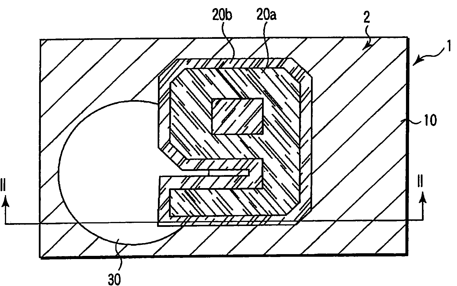
Fig. 1 is the vertical view that the display body of first embodiment of the present invention represented in summary.
Fig. 2 is the summary sectional view along the II-II line of display body shown in Figure 1.
Fig. 3 is the figure that expression is incident to an example of the relation between the emitted diffraction light of the illumination light of diffraction grating and diffraction grating.
Fig. 4 is the vertical view that an example in light scattering zone represented in summary.
Fig. 5 is the vertical view of an example of the adoptable structure in expression light scattering zone.
Fig. 6 is the vertical view of other examples of the adoptable structure in expression light scattering zone.
Fig. 7 is the vertical view of other examples of the adoptable structure in expression light scattering zone.
Fig. 8 is the vertical view of other examples of the adoptable structure in expression light scattering zone.
Fig. 9 is the vertical view of other examples of the adoptable structure in expression light scattering zone.
Figure 10 is the vertical view that the display body of second embodiment of the present invention represented in summary.
Figure 11 is the vertical view that the variation of display body shown in Figure 10 represented in summary.
Figure 12 is the stereographic map of an example in the summary light scattering zone of representing to comprise the protuberance of the shape beyond the wire and/or recess.
Figure 13 is the stereographic map of other examples in the summary light scattering zone of representing to comprise the protuberance of the shape beyond traditional thread binding and/or recess.
Figure 14 is the vertical view that an example of article that display body is supported represented in summary.
Embodiment
Below, the embodiment that present invention will be described in detail with reference to the accompanying.Wherein, for the textural element of bringing into play identical or similar function additional phase reference marks together in whole accompanying drawings, and the repetitive description thereof will be omitted.
Fig. 1 is the vertical view that the display body of first embodiment of the present invention represented in summary.Fig. 2 is the summary sectional view along the II-II line of display body shown in Figure 1.
Layer of reflective material 51 covers the back side of transmitance material layer 50.On the interface of transmitance material layer 50 and layer of reflective material 51, be provided with sag and swell.Wait until aftermentioned for this sag and swell.Layer of reflective material 51 covers at least on the interface of transmitance material layer 50 and shows that by sag and swell the zone of picture gets final product.Knitting layer 52 is located on the layer of reflective material 51.
As the material of transmitance material 50, thermoplastic resin or ultraviolet curable resin etc. are preferred forming by the transfer printing of using master aspect the sag and swell.Utilizing under the situation of salient point,, then can easily obtain accurate volume production duplicate if on master, form accurately in advance and diffraction grating described later zone 10 and light scattering zone 20a and the corresponding sag and swell of 20b.
For transmission material layer 50, consider the easy formation of surface strength and sag and swell etc., also can adopt the structure more than 2 layers.In addition,,, also can in transmission material layer 50, mix dyestuff etc., make this dyestuff absorb the light of the wavelength of appointment for resultant metallic luster look is changed into the color different with it using under the situation of metal as the material of layer of reflective material 51.
The effect that layer of reflective material 51 performances improve the reflectivity at the interface that is provided with sag and swell.As the material of layer of reflective material 51, for example can use metal materials such as Al, Ag.In addition, the material of layer of reflective material 51 transparent material different that also can be refractive indexes such as dielectric material with transmitance material layer 50.Layer of reflective material 51 is not limited to individual layer, also can be multilayer film.
In addition, in Fig. 2, described to observe the structure of display body 1, but also can adopt the structure of observing display body 1 from layer of reflective material 51 sides from transmitance material layer 50 sides.
Then, the sag and swell that is located on the layer 2 is described.
In diffraction grating zone 10, on the interface of transmitance material layer 50 and layer of reflective material 51, formed the diffraction grating pattern that the diffraction grating by relief type constitutes.This diffraction grating is for example arranged a plurality of grooves and is formed.In addition, term " diffraction grating " refers to the structure that produces diffracted wave by irradiating illumination light, for example is made as except parallel and equally spaced dispose the common diffraction grating of a plurality of grooves, also comprises the interference fringe that writes down in the hologram.In addition, the part that groove or groove clipped is called " grid stroke ".
The degree of depth that constitutes the groove of diffraction grating for example is made as in the scope of 0.1~1 μ m.In addition, the grating constant of diffraction grating for example is made as in the scope of 0.5~2 μ m.
In each of light scattering zone 20a and 20b, on the interface of transmitance material layer 50 and layer of reflective material 51, be provided with the protuberance and/or the recess of a plurality of linearities of direction unanimity.In addition, in regional 20a and regional 20b, the protuberance of linearity and/or the direction of recess are different mutually.
Under the situation of regional 20a or 20b being thrown light on from the normal direction in zone, this zone in the face vertical with the length direction of the protuberance of linearity and/or recess with the widest angle of emergence scope, be that wide-angle penetrates scattered light, with the parallel and vertical face of the length direction of the protuberance of linearity and/or recess with the interarea of above-mentioned zone in penetrate scattered light with the narrowest angle of emergence scope.Below, the size that the light scattering zone is penetrated the angular range of the scattered light more than certain intensity shows with term " light scattering energy ".For example, under the situation of using term " light scattering energy ", above-mentioned optical characteristics can be recited as " each of regional 20a and 20b presents minimum light scattering energy on the length direction of the protuberance of linearity and/or recess, present maximum light scattering energy on perpendicular direction ".In addition, with the light scattering of maximum can with the light scattering of minimum can the character that fully exists of difference be called " light scattering can anisotropy ".
The protuberance of linearity and/or the length of recess for example are made as more than the 10 μ m.In addition, the width of these protuberances and/or recess for example is made as in the scope of 0.1~10 μ m.In addition, the height of these protuberances and/or recess or the degree of depth for example are made as in the scope of 0.1~10 μ m.
In zone 30, on the interface of transmitance material layer 50 and layer of reflective material 51, sag and swell is not set.That is, in zone 30, transmitance material layer 50 is tabular surfaces with the interface of layer of reflective material 51.
Under the situation that constitutes layer 2 by multiple unit,, then easily resulting picture is replaced in their arrangement and envisioned if know the visual effect of each unit.So, can according to Digital Image Data easily determine each pixel the unit that should use.Therefore, the design of display body 1 becomes easy at this moment.
In order to make intersegmental or pixel mesopic vision effect difference, can utilize the content of following explanation.
At first, the visual effect that obtains by diffraction grating zone 10 with reference to description of drawings.
Fig. 3 is the figure that expression is incident to an example of the relation between the emitted diffraction light of the illumination light of diffraction grating and diffraction grating.
If make illumination light 71 be incident to diffraction grating 11 from the direction vertical with grid stroke with incident angle α ', then diffraction grating 11 is with 1 diffraction light 73 of angle of emergence β ejaculation as representative diffraction light.The reflection angle or the angle of emergence α of the normal reflection light of diffraction grating 11 (0 diffraction light) 72 equate on absolute value with incident angle α ', and with respect to normal symmetry (α, β are made as positive dirction with clockwise direction).When the wavelength that angle [alpha] and angle beta are made as d (nm), illumination light 71 in the grating constant with diffraction grating 11 is made as λ (nm), satisfy the relation shown in the following formula (1).
d=λ/(sinα-sinβ) (1)
By above-mentioned formula (1) as can be known, under the situation that makes white light incident, the angle of emergence of 1 diffraction light is different and different according to wavelength.That is, diffraction grating 11 has the branch light action, and the color in diffraction grating zone 10 changes with seven looks along with changing the observation place.
In addition, the color felt based on certain observation condition of observer changes according to grating constant d.
For example, be made as diffraction grating 11 and on the direction vertical, penetrate 1 time diffraction light 73 with respect to this grating face.That is, the angle of emergence β that is made as 1 diffraction light 73 is 0 °.At this moment, if the absolute value of the angle of emergence of the incident angle of illumination light 71 and 0 diffraction light 72 is made as α
N, the then following simplification of formula (1).
d=λ/sinα
N (2)
By formula (2) as can be known, feel certain color, the absolute value α of wavelength X that will be corresponding, the incident angle of illumination light 71 in order to make the observer with this color
NBe set at grating constant d and satisfy the relation shown in the formula (2) and get final product.For example, be that the white light of 400~700nm is an illumination light 71 if establish wavelength, with the absolute value α of the incident angle of illumination light 71
NBe made as 45 °, use is that the inverse of grating constant is the diffraction grating that distributes in the scope of 1800~1000/mm with the spatial frequency of diffraction grating, then spatial frequency is that the part of 1600/mm degree appears as blueness, and the part of 1100/mm degree appears as redness.Therefore, by making the spatial frequency difference of diffraction grating between intersegmental or unit, can make their Show Color difference.
In addition, the more little easy more formation of the spatial frequency of diffraction grating.Therefore, the common diffraction grating that is used for display body is made as spatial frequency 500~1600/mm mostly.
In the above description, suppose to make illumination light 71 to be incident to diffraction grating 11 from the direction vertical with grid stroke.According to this state, if direction of observation is being made as under certain state, make diffraction grating 11 around its normal rotation, then the effective value of grating constant d changes according to its anglec of rotation.As a result, the color that the observer felt changes.In addition, if this anglec of rotation is fully big, then the observer can't feel diffraction light on above-mentioned direction of observation.So, by making the orientation difference of grid stroke between intersegmental or unit, can make their Show Color difference, or change this unit and look luminous direction owing to diffraction light.
In addition, if the degree of depth of the groove that constitutes diffraction grating 11 is increased, then diffraction efficiency changes.In addition, if diffraction grating is increased with respect to the area ratio of section or unit, then the diffraction light intensity becomes bigger.
Therefore,, then can make these sections or unit show different colors, perhaps can set observable condition if in the spatial frequency and/or the orientation difference of intersegmental or unit chien shih diffraction grating.In addition, if intersegmental or unit chien shih formed diffraction grating 11 groove the degree of depth and diffraction grating 11 with respect to the area of section or unit than at least one side different, then can make the brightness difference of these sections or unit.So,, can show full-color picture and space image iseikonia by utilizing these methods.
Then, the visual effect that obtains by light scattering zone 20a and 20b with reference to description of drawings.
Fig. 4 is the vertical view that an example in light scattering zone represented in summary.
In addition, in each light scattering zone 20, light scattering structure 25 also can not exclusively be arranged in parallel.As long as light scattering zone 20 has sufficient light scattering energy anisotropy, in this light scattering zone 20, for example the length direction of light scattering structure 25 that also can be a part of intersects with the length direction of other a part of light scattering structures 25.Below, with the direction of the main surface parallel in light scattering zone 20 among, with light scattering zone 20 present minimum light scattering can direction be called " direction of orientation ", with light scattering zone 20 present maximum light scattering can direction be called " light scattering axle ".In the present embodiment since with the structure of linearity as essential structure, so direction of orientation and light scattering axle quadrature.
In light scattering zone 20 shown in Figure 4, the direction of being represented by arrow 26 is a direction of orientation, and the direction of being represented by arrow 27 is the light scattering axle.For example, if thrown light in light scattering zone 20 from the vergence direction vertical with direction of orientation 26, and the light scattering zone 20 that detects by an unaided eye from the front, then light scattering zone 20 is owing to its higher light scattering energy looks brighter.On the other hand, if thrown light in light scattering zone 20 from the vergence direction vertical with light scattering axle 27, and the light scattering zone 20 that detects by an unaided eye from the front, then light scattering zone 20 is owing to its lower light scattering energy looks darker.
Hence one can see that, and for example under the situation in this light scattering zone 20 of from vergence direction being thrown light in light scattering zone 20 and detect by an unaided eye from the front, if make light scattering zone 20 around its normal direction rotation, then its brightness changes.So, for example in light scattering shown in Figure 1 zone 20a and light scattering zone 20b, adopt identical construction and under the different situation of the direction that only makes the light scattering axle between these regional 20a and 20b, when regional 20a looks the brightest, zone 20b looks darker, when regional 20a looked the darkest, regional 20b looked brighter.In addition, when regional 20b looked the brightest, regional 20a looked darker, and when regional 20b looked the darkest, regional 20a looked brighter.
That is,, can make the difference that produces lightness between them by in regional 20a and regional 20b, making light scattering axle 27 different.Therefore, can show picture thus.Especially, the differential seat angle of the light scattering axle 27 by making regional 20a and regional 20b is enough (though also depend on the size of lighting source, but for example being configured in general indoor on the ceiling mostly at lighting source is more than 30 °) or make light scattering anisotropy separately fully big, separately regional shown picture can detect by an unaided eye under different respectively observation conditions.By using the light scattering structure of light scattering axle quadrature as light scattering zone 20a and 20b, thereby the condition that can observe by separately regional shown picture becomes diverse condition, can observe picture separately reliably respectively.
The lightness in light scattering zone 20 also can be controlled by additive method.
For example, the width of light scattering structure 25 is big more, and the light scattering on the direction of light scattering axle 27 can be more little.On the other hand, if it is 25 elongated that light scattering is constructed, then the light scattering on the direction of orientation 26 can diminish.
The shape of light scattering structure 25 also can be all identical in 1 light scattering zone 20.Perhaps, 1 light scattering zone 20 also can comprise variform a plurality of protuberance and/or recess 25.
The design of light scattering energy is carried out in the light scattering zone 20 that only comprises the light scattering structure 25 of same shape easily.In addition, this light scattering zone 20 can be painted microfabrication devices such as device or steeper by the electronics line drawing and come high precision and easily form.On the other hand, the light scattering zone 20 according to comprising variform light scattering structure 25 can access the scattered light that has mild light intensity distributions in wider angular range.So, can show that the light and shade that is caused by the observation place changes little and stable white.
In addition, the orientation degree of order of light scattering structure 25 is high more, and the light scattering energy anisotropy in light scattering zone 20 is big more.
In light scattering zone 20, light scattering structure 25 both can also can dispose randomly by configuration regularly to a certain degree.For example, if the interval of the direction parallel with light scattering axle 27 of light scattering structure 25 is made as at random, the light intensity distributions of the scattered light on then vertical with direction of orientation 26 direction becomes mild.Therefore, suppressed variation with corresponding whiteness of viewing angle or lightness.
In addition,, then can make more incident light scattering, therefore can under the condition that light scattering can anisotropy be worsened, strengthen scattered intensity if on the direction parallel, dwindle the interval of light scattering structure 25 with light scattering axle 27.For example, if the equispaced of the structure of the light scattering on the direction parallel with light scattering axle 27 25 is below the 10 μ m, then can access the light scattering intensity of the good demonstration of enough realization visuognosis.
In addition, if make this equispaced fully little, then under the situation about being made of a plurality of light scattering unit in light scattering zone 20, the size that can enough make the light scattering unit is about 100 μ m.At this moment, can show picture with the fineness below the resolution of human eye under the common observation condition.That is the picture that, can show enough high-fineness.
In Fig. 1, disposed light scattering the axle roughly regional 20a of two light scattering and the 20b of quadrature, but also can dispose the different light scattering zone more than three of light scattering axle.
Fig. 5~Fig. 7 is the vertical view of example that expression can be used for the structure in light scattering zone.In Fig. 5~Fig. 7, white portion is respectively corresponding to protuberance or recess.
In the light scattering zone 20 of Fig. 5, light scattering structure 25 is arranged along the y direction.In the light scattering zone 20 of Fig. 6, light scattering structure 25 is arranged along the direction that is rotated counterclockwise 45 ° from the y direction.In the light scattering zone 20 of Fig. 7, light scattering structure 25 is along arranging with the x direction of y direction quadrature.
Like this, if the gray scale demonstration then for example can be carried out in the different light scattering zone more than three of configuration light scattering axle, or make the variation of picture complicated more along with the orientation that changes display body 1.For example, by changing the orientation of display body 1, also can change picture in the mode of animation.
Fig. 8 and Fig. 9 are the vertical views of other examples that expression can be used for the structure in light scattering zone.
In the light scattering zone 20 of Fig. 8, light scattering structure 25 is arranged along the y direction.In the light scattering zone 20 of Fig. 9, light scattering structure 25 is arranged along the x direction.
Fig. 8 and light scattering shown in Figure 9 structure 25 and Fig. 5~light scattering structure 25 shown in Figure 7 is compared, and width is wideer.Thus, the emitted scattered light in Fig. 8 and light scattering shown in Figure 9 zone 20 and Fig. 5~light scattering zone 20 emitted scattered lights shown in Figure 7 are compared, to the diffusion of the direction vertical with direction of orientation 26 still less.
Under the few situation of the diffusion of scattered light, scattered light grow during from the observation of definite position, therefore, for the different a plurality of zones of width identical by the direction of light scattering axle 26 and light scattering structure 25, the picture that constitutes of light scattering zone 20 shown in Figure 5 and light scattering zone 20 shown in Figure 8 for example, when the position of regulation is observed, looking becomes picture with deep or light.
In addition, the light scattering of Figure 1 and Figure 2 zone 20a and 20b are not limited to Fig. 5~Fig. 7 and Fig. 8 and light scattering zone 20 shown in Figure 9, can adopt various structures.
As mentioned above, has clear and definite switching effect by the light scattering zone 20a of Fig. 1 and the picture of 20b demonstration.That is, two pictures that shown by two light scattering zone 20a with mutually different light scattering axles 27 and 20b look and do not mix, and can observe clear respectively independently by naked eyes.In addition, by a plurality of light scattering zones 20 with different light scattering axles 27 are set, can make display body 1 show picture according to the quantity identical with the light scattering axle that is provided with 27.Thus, the picture that can also produce the cartoon type that the variation by the observation place causes changes.
The light scattering zone 20 that comprises the light scattering structure 25 of 2 values structures can utilize the device with microfabrication ability to make with comparalive ease, can also easily carry out the setting of shape etc.The light scattering zone 20 that comprises the light scattering structure 25 of continually varying structure is recorded in speckle on photosensitive material, for example photoresist by the interference that utilizes laser, can easily make.Is 50% and be 100% not have under the situation of even surface when continually varying is constructed at the area of the part that is provided with light scattering structure 25 when 2 values are constructed with respect to the area in light scattering zone 20, and it is the highest that 25 scattering efficiency is constructed in the light scattering in the light scattering zone 20.
The layer 2 of the display body 1 of Figure 1 and Figure 2 comprises regional 20a of two different mutually light scattering of light scattering axle and 20b.Light scattering zone 20a shows character " 9 " that light scattering zone 20b shows the edge of this character " 9 " as picture in addition as picture.
In the display body 1 of Fig. 1, the light scattering axle separately of light scattering zone 20a and 20b is mutually orthogonal.As mentioned above, observing from the directions vertical with respect to direction of orientation 26 under the situation of light scattering zone 20a or 20b, the display light diffusion therefore regardless of viewing angle, can both be observed bright picture.Therefore, if observe display body 1 from the direction vertical with the direction of orientation 26 of light scattering zone 20a, then only character " 9 " looks whiter, and the edge looks darker.On the other hand, if observe display body 1 from the direction vertical with the direction of orientation 26 of light scattering zone 20b, then only the edge of " 9 " looks whiter.That is, the display body 1 of Fig. 1 is owing to comprise regional 20a of two different mutually light scattering of light scattering axle and 20b, and therefore the light and shade of regional 20a and 20b reverses according to the orientation of display body 1.
The display body 1 of Figure 1 and Figure 2 is owing to comprise two light scattering zone 20a and the 20b that the direction of light scattering axle 27 is different mutually, therefore can be from observing the picture that is predetermined respectively with the corresponding different direction of scattering axle.Though the variation of the observed picture in this position according to the observation also can be by 10 performances of diffraction grating zone, different with the performance of seven colours in diffraction grating zone 10, in wider observation place scope, look it is almost uniform whiteness.
In addition, more than enumerated Fig. 2 as an example transmission material layer 50 in visibility region, do not have the situation of the absorption band of appointment, white scattered light has been described.Comprise that in transmission material layer 50 scattered light in light scattering zone 20 is the scattered light of the wavelength components of transmission transmission material layer 50 under the situation of dyestuff etc.
The display body 1 of Figure 1 and Figure 2 also comprises the zone 30 that sag and swell is not set except diffraction grating zone 10 and light scattering zone 20a and 20b.Zone 30 is except the position of observing normal reflection light, even change the observation place, the picture of feeling does not change yet.Under the situation that layer 2 is made of transparent material layer shown in Figure 2 50 and layer of reflective material 51, zone 30 presents the metallicity outward appearance of layer of reflective material 51.
Promptly, the display body 1 of Figure 1 and Figure 2 comprehensively possesses: have the visual effect that performance greatly changes along with the observation place diffraction grating zone 10, have mutually orthogonal light scattering axle 27 and have the switching of picture and zone 30 that two light scattering zone 20a of stable observing effect and 20b and performance do not change along with viewpoint, therefore, this display body 1 has complicated visual effect.And then, in the display body 1 of Figure 1 and Figure 2, each regional independent displaying picture, therefore with only, show that by a certain side among diffraction grating zone 10 or light scattering zone 20a and the 20b display body of picture compares, has complicated more visual effect, can be very easily and carry out difference with similar product reliably, improved antifalse effect thus.
The display body 1 of Figure 1 and Figure 2 is by each of suitably design diffraction grating zone 10 and light scattering zone 20a and 20b, can Show Color and different various pictures such as lightness.Therefore, the color and the lightness of the image that can show according to hope design diffraction grating zone 10 and light scattering zone 20a and 20b.In addition, in the display body 1 of Figure 1 and Figure 2, diffraction grating 11 and light scattering structure 25 all are made of concavo-convex, therefore only by concavo-convex duplicating, just can critically be easy to make under the state of the structure of keeping both and position relation and function.Strengthened for reliability with the display body 1 of high precision manufacturing, strengthened the reliability that the true and false is judged as the display body of genuine piece.
And then the display body of Figure 1 and Figure 21 is owing to comprise diffraction grating zone 10 and light scattering zone 20a and 20b, so the performance of picture changes according to the observation place.This visual effect can't be reproduced by this display body 1 of color dub.In addition, even will carry out forgery/imitation, also be difficult to correctly reproduce the sag and swell of precision with diverse two kinds of effects to the display body 1 of Figure 1 and Figure 2.And, even by having utilized optical reproducing method, also can't duplicate the light scattering structure of the display body 1 of Figure 1 and Figure 2 from the diffraction light of diffraction grating 11.
Therefore, based on the difficulty of distinctive visual effect and forgery/imitation, the display body 1 of Figure 1 and Figure 2 for example goes for securities class and various card, passport etc. as carrying out the high security optical media that the true and false is judged easily.
In addition, in the display body 1 of Figure 1 and Figure 2, also can omit diffraction grating zone 10.The display body of having omitted diffraction grating zone 10 comprehensively possesses the zone 30 that two light scattering zone 20a of switching with picture and stable observing effect and 20b and performance do not change according to viewpoint, therefore has complicated visual effect.In this display body, therefore with only each regional independent displaying picture shows that by 1 light scattering zone 20a or 20b the display body of picture compares, and has complicated more visual effect, can be very easily and carry out difference with similar product reliably, improved antifalse effect thus.
Then, other embodiments of the present invention are described.
Figure 10 is the vertical view that the display body of second embodiment of the present invention represented in summary.
In display body shown in Figure 10 1, diffraction grating zone 10 comprises a plurality of diffraction grating unit 12a~12f that the orientation is different.
In Figure 10, added the diffraction grating unit of identical reference marks because the orientation of diffraction grating is roughly the same, so penetrate the diffraction light corresponding with orientation separately.Therefore, added the diffraction grating unit demonstration of identical reference marks as the pixel that is used as having identical visual effect.Relative therewith, diffraction grating unit 12a~12f is because therefore the orientation difference of diffraction grating separately has different visual effects.That is, the display body 1 of Figure 10 comprises six diffraction grating zones with different visual effects.Therefore, the diffraction grating zone of the display body 1 of Figure 10 has according to the observation the different and changeful performance of condition.
In addition, in display body shown in Figure 10 1, light scattering zone 20a comprises the direction of orientation a plurality of light scattering unit 21a parallel with the direction that is rotated counterclockwise 45 ° from the x direction of light scattering structure.Light scattering zone 20a as pixel, forms the picture of " 9 " with a plurality of light scattering unit 21a.On the other hand, a plurality of light scattering unit 21b of the included light scattering of the light scattering zone 20b direction of orientation that comprises the light scattering structure and the light scattering unit 21a direction of orientation quadrature of constructing.Light scattering zone 20b as pixel, forms the picture that the picture to light scattering zone 20a shown " 9 " carries out deburring with a plurality of light scattering unit 21b.
The light scattering zone 20a of display body 1 shown in Figure 10 and 20b are owing to the direction of orientation quadrature that constitutes these regional light scattering unit 21a and the light scattering among 21b structure, so mutual light scattering axle quadrature.Therefore, if the display body 1 of Figure 10 is thrown light on and from top view from the direction that is rotated counterclockwise 45 ° with respect to the x direction, then in the 20b of light scattering zone, observe stronger scattered light, on the other hand, do not observe scattered light or observe very faint scattered light in the 20a of light scattering zone, therefore the picture of " 9 " looks darker.In addition, if the display body 1 of Figure 10 is thrown light on and from top view from 45 ° the direction of turning clockwise with respect to the x direction of principal axis, then in the 20a of light scattering zone, observe stronger scattered light, do not observe scattered light or observe very faint scattered light in the 20b of light scattering zone, the picture that therefore shows " 9 " looks than looking darker picture around the Bai Erqi.That is, every angle half-twist with illumination, the picture of " 9 " reverses with the light and shade of its picture on every side.
The size of diffraction grating unit 12a~12f and light scattering unit 21a and 21b is preferably below the 300 μ m.Especially, under the less situation of display body 1, consider, be preferably below the 100 μ m near the situation of observing.If each unit following sizes that are these numerical value, then under common observation condition, discrimination unit with the naked eye can realize the raising of antifalse effect and aesthetic appearance, ornamental raising.
As mentioned above, display body shown in Figure 10 1 is because the diffraction grating zone 10 that the different mutually diffraction grating unit 12a~12f in orientation constitutes and two light scattering zone 20a that are made of respectively light scattering unit 21a with mutually orthogonal light scattering axle 27 and 21b and 20b show picture respectively independently, therefore with only, compare by 1 among diffraction grating zone 10 and light scattering zone 20a and the 20b or 2 display body that show picture, have complicated more visual effect.Thus, can be very easily and carry out difference with similar product reliably.
In addition, display body 1 shown in Figure 10 constitutes picture with diffraction grating unit 12a~12f and light scattering unit 21a and 21b as pixel, therefore can carry out the configuration of diffraction grating or light scattering structure according to Digital Image Data according to each pixel easily, can easily make the picture of display body 1 become complexity/high-precision picture.Thus, can improve visual effect, and further improve antifalse effect.
In addition, in the display body 1 shown in Figure 10, diffraction grating 11 and light scattering structure 25 all are made of concavo-convex, therefore only by concavo-convex duplicating, just can critically be easy to make under the state of the structure of keeping both and position relation and function.As mentioned above, strengthened for reliability, strengthened the reliability that the true and false is judged as the display body of genuine piece with the display body 1 of high precision manufacturing.
And then, even will carry out the forgery/imitation of display body shown in Figure 10 1, also be difficult to correctly reproduce the structure of precision with these visual effects.In addition, even by having utilized optical reproducing method, also can't duplicate the light scattering structure of display body shown in Figure 10 1 from the diffraction light of diffraction grating 11.
Therefore, based on the difficulty of distinctive visual effect and forgery/imitation, display body 1 shown in Figure 10 for example can be applied flexibly in securities class or various card, passport etc. as can easily carrying out the high security optical media that the true and false is judged.
The variation of display body shown in Figure 10 1 then, is described.
Figure 11 is the vertical view that the variation of display body shown in Figure 10 represented in summary.
In display body shown in Figure 11 1, the diffraction grating zone 10a that is made of diffraction grating unit 12a forms the picture of " 0 ", the diffraction grating zone 10b that is made of diffraction grating unit 12b forms the picture of ": ", the light scattering zone 20a that is made of light scattering unit 21a forms the picture of " 1 ", and the regional 20b of light scattering that is made of light scattering unit 21b forms the picture of " 9 ".
In display body shown in Figure 11 1, the light scattering axle of light scattering zone 20a and light scattering zone 20b is quadrature almost.Therefore, only observe a side picture, and only observe the opposing party's picture in other observation places in certain observation place.That is, can not observe the both sides' of light scattering zone 20a and light scattering zone 20b picture.
In addition, in display body shown in Figure 11 1, the orientation of the diffraction grating of diffraction grating zone 10a and diffraction grating zone 10b is different mutually.Therefore, diffraction grating zone 10a looks that the observation place of sending seven glories looks that with diffraction grating zone 10b the observation place of sending seven glories is different.
And then in the display body 1 of Figure 11, among diffraction grating zone 10b and the light scattering zone 20b, inner sag and swell is roughly towards identical direction, so position difference according to the observation, can observe the two picture, or only observe a certain side's picture.
As mentioned above, display body shown in Figure 11 1 is because two diffraction grating zone 10a that are made of respectively different mutually diffraction grating unit 12a in orientation and 12b and 10b and two light scattering zone 20a that are made of respectively light scattering unit 21a with mutually orthogonal light scattering axle 27 and 21b and 20b show picture respectively independently, therefore with omitted these zones in the display body more than 1 compare, have complicated more visual effect.Thus, can be very easily and carry out difference with similar product reliably.
In addition, in the display body 1 shown in Figure 10, diffraction grating 11 and light scattering structure 25 all are made of concavo-convex, therefore only by concavo-convex duplicating, just can critically be easy to make under the state of the structure of keeping both and position relation and function.Stably strengthened for reliability, strengthened the reliability that the true and false is judged as the display body of genuine piece with the display body 1 of high precision manufacturing.
And then, even will carry out the forgery/imitation of display body shown in Figure 11 1, also be difficult to correctly reproduce the structure of precision with these visual effects.In addition, even by having utilized optical reproducing method, also can't duplicate the light scattering structure of display body shown in Figure 11 1 from the diffraction light of diffraction grating 11.
Therefore, based on the difficulty of distinctive visual effect and forgery/imitation, display body 1 shown in Figure 11 for example can be applied flexibly in securities class or various card, passport etc. as can easily carrying out the high security optical media that the true and false is judged.
More than Shuo Ming display body 1 also can be except the light scattering zone 20a of the light scattering structure 25 that comprises wire and 20b etc., further has the protuberance that comprises other shapes and/or the light scattering zone of recess.
Figure 12 and Figure 13 are the stereographic maps of the example in the summary light scattering zone of representing to comprise the protuberance of the shape beyond the wire and/or recess.
The light scattering zone 20 ' of Figure 12 comprises a plurality of protuberance 25a of rectangular shape.Direction of orientation 26 ' and the x direction almost parallel of a plurality of protuberance 25a.The light scattering zone 20 ' of Figure 13 comprises a plurality of protuberance 25b of elliptical shape.Direction of orientation 26 ' and the x direction almost parallel of a plurality of protuberance 25b.
In the light scattering zone 20 ' of Figure 12 and Figure 13, light scattering axle 27 ' and y direction almost parallel.But, protuberance 25a that the light scattering zone 20 ' of Figure 12 and Figure 13 is included and 25b are because the size of the size of x direction and y direction smaller, for example be in 1~5 the scope, therefore compare with the protuberance and/or the recess 25 of above-mentioned wire, light scattering is can anisotropy less.Thus, though scattered light can be observed in the light scattering zone 20 ' of Figure 12 and Figure 13, the variation of the performance corresponding with the observation place is less.
Therefore, by appending this light scattering zone 20 ', can make the visual effect of display body 1 complicated more.
Above-mentioned display body 1 also can be installed in and be used as false proof medium on the article such as printed article and use.
Figure 14 is the vertical view that an example of tape label article that display body is supported represented in summary.
The tape label article of Figure 14 are a kind of modes of the suitable example of display body 1, and the suitable example of display body 1 is not limited to the mode of Figure 14.For example, display body 1 is being applicable under the situation of the article that printed article is such, also can under the mode that is called as fiber (thread) (being also referred to as band, silk, filiform, safe strap etc.), in paper, copy into.In addition, display body 1 can comprise adhesive coating 52 as shown in Figure 2, therefore can easily be attached on the various article to be suitable for.
In addition, the tape label article can not be printed matters also.That is, display body 1 also can be bearing on the senior article such as artistic products.
To those skilled in the art, be easy to be further improved and be out of shape.Therefore, the present invention its wider aspect, should not be defined in specific record or representational mode in this record.Therefore, in the real meaning or scope that do not break away from by the included notion of the present invention of additional claim and its full scope of equivalents defined, can carry out various distortion.
Claims (15)
Priority Applications (1)
| Application Number | Priority Date | Filing Date | Title |
|---|---|---|---|
| CN201510630039.6A CN105158830B (en) | 2008-04-18 | 2008-04-18 | Display body and labeled article |
Applications Claiming Priority (1)
| Application Number | Priority Date | Filing Date | Title |
|---|---|---|---|
| PCT/JP2008/057611 WO2009128168A1 (en) | 2008-04-18 | 2008-04-18 | Labeling material and labeled goods item |
Related Child Applications (1)
| Application Number | Title | Priority Date | Filing Date |
|---|---|---|---|
| CN201510630039.6A Division CN105158830B (en) | 2008-04-18 | 2008-04-18 | Display body and labeled article |
Publications (1)
| Publication Number | Publication Date |
|---|---|
| CN101910876A true CN101910876A (en) | 2010-12-08 |
Family
ID=41198880
Family Applications (1)
| Application Number | Title | Priority Date | Filing Date |
|---|---|---|---|
| CN2008801248346A Pending CN101910876A (en) | 2008-04-18 | 2008-04-18 | Display body and labeled article |
Country Status (7)
| Country | Link |
|---|---|
| US (4) | US8982465B2 (en) |
| EP (3) | EP3040746B1 (en) |
| KR (1) | KR101105912B1 (en) |
| CN (1) | CN101910876A (en) |
| CA (1) | CA2708526C (en) |
| ES (1) | ES2620654T3 (en) |
| WO (1) | WO2009128168A1 (en) |
Cited By (6)
| Publication number | Priority date | Publication date | Assignee | Title |
|---|---|---|---|---|
| CN107111022A (en) * | 2015-01-08 | 2017-08-29 | 凸版印刷株式会社 | Display body and article |
| CN107111019A (en) * | 2014-10-28 | 2017-08-29 | 大日本印刷株式会社 | Sag and swell body and security medium |
| CN107850708A (en) * | 2015-07-15 | 2018-03-27 | 凸版印刷株式会社 | Display body |
| CN110167762A (en) * | 2017-03-17 | 2019-08-23 | 捷德货币技术有限责任公司 | Security element with reflection colour filter characteristic |
| TWI766106B (en) * | 2017-09-29 | 2022-06-01 | 荷蘭商耐克創新有限合夥公司 | Articles having structural color |
| CN115513267A (en) * | 2022-09-29 | 2022-12-23 | 京东方科技集团股份有限公司 | A display substrate and a display device |
Families Citing this family (43)
| Publication number | Priority date | Publication date | Assignee | Title |
|---|---|---|---|---|
| CN101910876A (en) * | 2008-04-18 | 2010-12-08 | 凸版印刷株式会社 | Display body and labeled article |
| US20110085241A1 (en) * | 2009-10-13 | 2011-04-14 | Purchase Ken G | Transmissive optical microstructure substrates that produce visible patterns |
| JP2011118034A (en) * | 2009-12-01 | 2011-06-16 | Toppan Printing Co Ltd | Image forming body |
| EP2508922B2 (en) | 2009-12-01 | 2023-08-16 | Toppan Printing Co., Ltd. | Display body and labeled article |
| DE102010047250A1 (en) * | 2009-12-04 | 2011-06-09 | Giesecke & Devrient Gmbh | Security element, value document with such a security element and manufacturing method of a security element |
| JP5609096B2 (en) * | 2009-12-15 | 2014-10-22 | 凸版印刷株式会社 | Blank media and transfer foil |
| US8939621B2 (en) * | 2010-06-17 | 2015-01-27 | Ford Global Technologies, Llc | Headlamp with backlit side bezel signature image |
| JP2012088598A (en) * | 2010-10-21 | 2012-05-10 | Toppan Printing Co Ltd | Display body and labeled article |
| JP5659786B2 (en) * | 2010-12-27 | 2015-01-28 | 凸版印刷株式会社 | Laminated body and method for producing the same |
| JP5827578B2 (en) * | 2011-02-14 | 2015-12-02 | 株式会社半導体エネルギー研究所 | Method for producing optical element |
| DE102011014114B3 (en) | 2011-03-15 | 2012-05-10 | Ovd Kinegram Ag | Multi-layer body and method for producing a multi-layer body |
| JP6382482B2 (en) * | 2011-06-16 | 2018-08-29 | 大日本印刷株式会社 | Diffraction grating recording medium |
| JP6382483B2 (en) * | 2011-10-12 | 2018-08-29 | 大日本印刷株式会社 | Diffraction grating recording medium |
| EP2635006B1 (en) * | 2012-03-02 | 2018-12-19 | LG Electronics, Inc. | Mobile terminal comprising an image module provided thereon |
| JP6037103B2 (en) * | 2012-05-22 | 2016-11-30 | 大日本印刷株式会社 | Uneven structure |
| JP2013246367A (en) * | 2012-05-28 | 2013-12-09 | Toppan Printing Co Ltd | Image display body and information medium |
| DE102012105571B4 (en) | 2012-06-26 | 2017-03-09 | Ovd Kinegram Ag | Decorative element as well as security document with a decorative element |
| JP6003450B2 (en) * | 2012-09-20 | 2016-10-05 | 凸版印刷株式会社 | Display and labeled goods |
| JP2014134739A (en) * | 2013-01-11 | 2014-07-24 | Toppan Printing Co Ltd | Image display body and information medium |
| WO2014141636A1 (en) * | 2013-03-12 | 2014-09-18 | 凸版印刷株式会社 | Display body |
| AU2014262357B2 (en) * | 2013-05-09 | 2018-05-17 | Idit Technologies Corp. | Nanostructure array diffractive optics for motion and animation display |
| JP6413297B2 (en) * | 2013-06-05 | 2018-10-31 | 凸版印刷株式会社 | Display and printed matter |
| JP6369032B2 (en) * | 2014-01-29 | 2018-08-08 | 凸版印刷株式会社 | Manufacturing method of image display device |
| JP5949860B2 (en) * | 2014-09-03 | 2016-07-13 | 凸版印刷株式会社 | Image display body, article |
| JP6520359B2 (en) * | 2015-04-30 | 2019-05-29 | 凸版印刷株式会社 | Display body, article, original plate, and method of producing original plate |
| KR102408530B1 (en) | 2015-06-02 | 2022-06-13 | 도판 인사츠 가부시키가이샤 | Laminate and manufacturing method for same |
| JP6676951B2 (en) * | 2015-07-15 | 2020-04-08 | 凸版印刷株式会社 | Display body |
| EP3370095B1 (en) | 2015-10-26 | 2019-08-28 | Toppan Printing Co., Ltd. | Display body |
| EP3568518B1 (en) | 2017-02-14 | 2020-09-09 | Nike Innovate C.V. | Anti-odor compositions, structures having anti-odor characteristics, methods of making the anti-odor compositions and the structures |
| DE102017005050A1 (en) | 2017-05-26 | 2018-11-29 | Giesecke+Devrient Currency Technology Gmbh | Security element with reflective surface area |
| DE102018103236A1 (en) * | 2018-02-14 | 2019-08-14 | Leonhard Kurz Stiftung & Co. Kg | Security element and method for producing a security element |
| WO2019182051A1 (en) * | 2018-03-20 | 2019-09-26 | 凸版印刷株式会社 | Optical element and authentication body |
| GB2573816B (en) | 2018-05-18 | 2021-06-09 | De La Rue Int Ltd | Security device and method of manufacture thereof |
| EP3819684B1 (en) * | 2018-07-05 | 2025-07-30 | Toppan Printing Co., Ltd. | Optical structure |
| JP6531858B2 (en) * | 2018-07-12 | 2019-06-19 | 凸版印刷株式会社 | Image display device, image display medium, and hologram ribbon |
| EP4249280B1 (en) | 2019-01-07 | 2025-04-23 | Toppan Printing Co., Ltd. | Indicator body and labeled printed matter |
| US11597996B2 (en) | 2019-06-26 | 2023-03-07 | Nike, Inc. | Structurally-colored articles and methods for making and using structurally-colored articles |
| US20210022444A1 (en) | 2019-07-26 | 2021-01-28 | Nike, Inc. | Structurally-colored articles and methods for making and using structurally-colored articles |
| US11986042B2 (en) | 2019-10-21 | 2024-05-21 | Nike, Inc. | Structurally-colored articles and methods for making and using structurally-colored articles |
| EP4107007B1 (en) | 2020-05-29 | 2023-08-30 | Nike Innovate C.V. | Structurally-colored articles and methods for making and using structurally-colored articles |
| US11889894B2 (en) | 2020-08-07 | 2024-02-06 | Nike, Inc. | Footwear article having concealing layer |
| US11241062B1 (en) | 2020-08-07 | 2022-02-08 | Nike, Inc. | Footwear article having repurposed material with structural-color concealing layer |
| US11129444B1 (en) | 2020-08-07 | 2021-09-28 | Nike, Inc. | Footwear article having repurposed material with concealing layer |
Family Cites Families (34)
| Publication number | Priority date | Publication date | Assignee | Title |
|---|---|---|---|---|
| US4589686A (en) * | 1980-11-05 | 1986-05-20 | Mcgrew Stephen P | Anticounterfeiting method and device |
| DE58909370D1 (en) | 1988-09-30 | 1995-09-07 | Landis & Gry Tech Innovat Ag | Bar code field and bar code reader. |
| JP2751721B2 (en) | 1992-03-26 | 1998-05-18 | 凸版印刷株式会社 | Display with diffraction grating pattern |
| JPH06278396A (en) * | 1993-03-26 | 1994-10-04 | Dainippon Printing Co Ltd | Forgery preventive printed matter, transfer sheet, manufacture of the matter using the sheet, and forgery preventing method |
| JP3458470B2 (en) * | 1994-08-22 | 2003-10-20 | 凸版印刷株式会社 | Diffraction grating pattern |
| DE4446368A1 (en) * | 1994-12-23 | 1996-06-27 | Giesecke & Devrient Gmbh | Data carrier with an optically variable element |
| DE19516741C2 (en) * | 1995-05-06 | 1997-05-07 | Kurz Leonhard Fa | Diffractive-optical structure arrangement |
| AUPO957297A0 (en) | 1997-10-02 | 1997-10-30 | Commonwealth Scientific And Industrial Research Organisation | Micrographic security device |
| JP2000131516A (en) | 1998-10-26 | 2000-05-12 | Toppan Printing Co Ltd | Diffraction grating pattern |
| HK1044960A1 (en) | 1999-10-19 | 2002-11-08 | Rolic Ag | Topologically structured polymer coating |
| DE10054503B4 (en) * | 2000-11-03 | 2005-02-03 | Ovd Kinegram Ag | Light diffractive binary lattice structure and security element with such a lattice structure |
| JP3982200B2 (en) * | 2001-04-27 | 2007-09-26 | 凸版印刷株式会社 | Display with light scattering pattern |
| JP2002328210A (en) * | 2001-05-02 | 2002-11-15 | Toppan Printing Co Ltd | Light scatterer and display using the same |
| JP4269537B2 (en) * | 2001-05-07 | 2009-05-27 | 凸版印刷株式会社 | Light scatterer and light scattering pattern and display using the same |
| JP2002341809A (en) * | 2001-05-14 | 2002-11-29 | Toppan Printing Co Ltd | Display comprising light scattering pattern and diffraction grating pattern |
| DE10127980C1 (en) * | 2001-06-08 | 2003-01-16 | Ovd Kinegram Ag Zug | Diffractive security element |
| DE10129938B4 (en) | 2001-06-20 | 2005-05-25 | Ovd Kinegram Ag | As an authenticity feature on a document arranged optically variable surface pattern |
| JP2003098324A (en) * | 2001-09-26 | 2003-04-03 | Toppan Printing Co Ltd | Light scattering pattern |
| DE10216562C1 (en) * | 2002-04-05 | 2003-12-11 | Ovd Kinegram Ag Zug | Security element with micro and macro structures |
| JP4501369B2 (en) * | 2003-06-30 | 2010-07-14 | 凸版印刷株式会社 | Optical sheet having light scattering elements |
| DE102004003984A1 (en) | 2004-01-26 | 2005-08-11 | Giesecke & Devrient Gmbh | Lattice image with one or more grid fields |
| JP4416161B2 (en) * | 2004-05-12 | 2010-02-17 | 大日本印刷株式会社 | Light diffraction structure |
| EP1771752B1 (en) | 2004-07-21 | 2020-10-07 | ROLIC Technologies AG | Anisotropic optical device and method for making same |
| JP4778261B2 (en) * | 2005-04-26 | 2011-09-21 | 日本電気株式会社 | Display device and terminal device |
| JP4779792B2 (en) * | 2006-04-27 | 2011-09-28 | 凸版印刷株式会社 | Information recording medium and information recording medium authenticity determination device |
| EP1855127A1 (en) | 2006-05-12 | 2007-11-14 | Rolic AG | Optically effective surface relief microstructures and method of making them |
| WO2008024813A2 (en) | 2006-08-22 | 2008-02-28 | Rynne Group, Llc | A discernment card and a discernment card business system using the discernment card |
| CA2631161C (en) * | 2006-09-27 | 2016-05-24 | Toppan Printing Co., Ltd. | Optical device, labeled article, optical kit and discrimination method |
| JP2008083599A (en) * | 2006-09-28 | 2008-04-10 | Toppan Printing Co Ltd | Optical element and display body using the same |
| JP5157115B2 (en) | 2006-09-28 | 2013-03-06 | 凸版印刷株式会社 | Display comprising diffraction grating and printed matter using the same |
| JP5157121B2 (en) * | 2006-10-24 | 2013-03-06 | 凸版印刷株式会社 | Display and printed matter |
| DE102007009646A1 (en) | 2007-02-26 | 2008-08-28 | Giesecke & Devrient Gmbh | Holographic grid image for security element of e.g. bank note, has grid fields which are achromatic grid fields, and formed of sub-ranges overlapping with one another, where dimension of sub-ranges lies below resolution limit of naked eye |
| CN101910876A (en) * | 2008-04-18 | 2010-12-08 | 凸版印刷株式会社 | Display body and labeled article |
| CN102472848B (en) * | 2009-08-13 | 2014-08-27 | 凸版印刷株式会社 | Image displays and labeled items |
-
2008
- 2008-04-18 CN CN2008801248346A patent/CN101910876A/en active Pending
- 2008-04-18 EP EP16155629.5A patent/EP3040746B1/en active Active
- 2008-04-18 WO PCT/JP2008/057611 patent/WO2009128168A1/en not_active Ceased
- 2008-04-18 EP EP08751881.7A patent/EP2264488B1/en not_active Revoked
- 2008-04-18 ES ES08751881.7T patent/ES2620654T3/en active Active
- 2008-04-18 KR KR1020107016365A patent/KR101105912B1/en not_active Expired - Fee Related
- 2008-04-18 EP EP16155630.3A patent/EP3040747B1/en active Active
- 2008-04-18 CA CA2708526A patent/CA2708526C/en active Active
-
2010
- 2010-06-17 US US12/801,635 patent/US8982465B2/en active Active
-
2015
- 2015-02-11 US US14/619,558 patent/US9387720B2/en active Active
-
2016
- 2016-06-08 US US15/176,718 patent/US9829610B2/en not_active Expired - Fee Related
-
2017
- 2017-10-17 US US15/785,901 patent/US10473831B2/en active Active
Cited By (8)
| Publication number | Priority date | Publication date | Assignee | Title |
|---|---|---|---|---|
| CN107111019A (en) * | 2014-10-28 | 2017-08-29 | 大日本印刷株式会社 | Sag and swell body and security medium |
| CN107111019B (en) * | 2014-10-28 | 2020-11-20 | 大日本印刷株式会社 | Concave-convex structure and safety medium |
| CN107111022A (en) * | 2015-01-08 | 2017-08-29 | 凸版印刷株式会社 | Display body and article |
| CN107850708A (en) * | 2015-07-15 | 2018-03-27 | 凸版印刷株式会社 | Display body |
| CN107850708B (en) * | 2015-07-15 | 2022-03-22 | 凸版印刷株式会社 | display |
| CN110167762A (en) * | 2017-03-17 | 2019-08-23 | 捷德货币技术有限责任公司 | Security element with reflection colour filter characteristic |
| TWI766106B (en) * | 2017-09-29 | 2022-06-01 | 荷蘭商耐克創新有限合夥公司 | Articles having structural color |
| CN115513267A (en) * | 2022-09-29 | 2022-12-23 | 京东方科技集团股份有限公司 | A display substrate and a display device |
Also Published As
| Publication number | Publication date |
|---|---|
| EP3040747B1 (en) | 2022-06-22 |
| CA2708526C (en) | 2012-02-21 |
| WO2009128168A1 (en) | 2009-10-22 |
| US20180038998A1 (en) | 2018-02-08 |
| EP2264488B1 (en) | 2016-12-28 |
| KR20100094595A (en) | 2010-08-26 |
| US9387720B2 (en) | 2016-07-12 |
| KR101105912B1 (en) | 2012-01-17 |
| US8982465B2 (en) | 2015-03-17 |
| CA2708526A1 (en) | 2009-10-22 |
| EP3040747A1 (en) | 2016-07-06 |
| US10473831B2 (en) | 2019-11-12 |
| EP3040746B1 (en) | 2022-06-22 |
| ES2620654T3 (en) | 2017-06-29 |
| US20100254007A1 (en) | 2010-10-07 |
| US20150151561A1 (en) | 2015-06-04 |
| EP2264488A4 (en) | 2012-10-17 |
| EP3040746A1 (en) | 2016-07-06 |
| EP2264488A1 (en) | 2010-12-22 |
| US9829610B2 (en) | 2017-11-28 |
| US20160279999A1 (en) | 2016-09-29 |
Similar Documents
| Publication | Publication Date | Title |
|---|---|---|
| CN101910876A (en) | Display body and labeled article | |
| JP5157121B2 (en) | Display and printed matter | |
| JP6237759B2 (en) | Display and labeled goods | |
| JP4420138B2 (en) | Display and printed information | |
| RU2478998C9 (en) | Image reproducing system and microoptic security system | |
| JP5303879B2 (en) | Display and labeled goods | |
| JP5272434B2 (en) | Indicator | |
| JP5143855B2 (en) | Display and labeled goods | |
| CN107835949B (en) | Display body, article, original plate, and method for manufacturing original plate | |
| US20210370701A1 (en) | Optical device and method of manufacture thereof | |
| US11247505B2 (en) | Optical structure and authentication body | |
| JP2012078447A (en) | Display body and article with label | |
| CN105158830B (en) | Display body and labeled article | |
| JP2013020084A (en) | Display body with computer-generated hologram, and labeled article | |
| JP2012163610A (en) | Display body and printed matter | |
| JP2012192568A (en) | Displaying body and method for determining authenticity |
Legal Events
| Date | Code | Title | Description |
|---|---|---|---|
| C06 | Publication | ||
| PB01 | Publication | ||
| C10 | Entry into substantive examination | ||
| SE01 | Entry into force of request for substantive examination | ||
| C12 | Rejection of a patent application after its publication | ||
| RJ01 | Rejection of invention patent application after publication |
Application publication date: 20101208 |