CN101902145A - Solar inverter and control method - Google Patents
Solar inverter and control method Download PDFInfo
- Publication number
- CN101902145A CN101902145A CN2010101966478A CN201010196647A CN101902145A CN 101902145 A CN101902145 A CN 101902145A CN 2010101966478 A CN2010101966478 A CN 2010101966478A CN 201010196647 A CN201010196647 A CN 201010196647A CN 101902145 A CN101902145 A CN 101902145A
- Authority
- CN
- China
- Prior art keywords
- power
- module
- threshold voltage
- voltage
- inverter
- Prior art date
- Legal status (The legal status is an assumption and is not a legal conclusion. Google has not performed a legal analysis and makes no representation as to the accuracy of the status listed.)
- Granted
Links
Images


Classifications
-
- G—PHYSICS
- G05—CONTROLLING; REGULATING
- G05F—SYSTEMS FOR REGULATING ELECTRIC OR MAGNETIC VARIABLES
- G05F1/00—Automatic systems in which deviations of an electric quantity from one or more predetermined values are detected at the output of the system and fed back to a device within the system to restore the detected quantity to its predetermined value or values, i.e. retroactive systems
- G05F1/66—Regulating electric power
- G05F1/67—Regulating electric power to the maximum power available from a generator, e.g. from solar cell
-
- H—ELECTRICITY
- H02—GENERATION; CONVERSION OR DISTRIBUTION OF ELECTRIC POWER
- H02J—CIRCUIT ARRANGEMENTS OR SYSTEMS FOR SUPPLYING OR DISTRIBUTING ELECTRIC POWER; SYSTEMS FOR STORING ELECTRIC ENERGY
- H02J3/00—Circuit arrangements for AC mains or AC distribution networks
- H02J3/38—Arrangements for parallely feeding a single network by two or more generators, converters or transformers
- H02J3/381—Dispersed generators
-
- H—ELECTRICITY
- H02—GENERATION; CONVERSION OR DISTRIBUTION OF ELECTRIC POWER
- H02M—APPARATUS FOR CONVERSION BETWEEN AC AND AC, BETWEEN AC AND DC, OR BETWEEN DC AND DC, AND FOR USE WITH MAINS OR SIMILAR POWER SUPPLY SYSTEMS; CONVERSION OF DC OR AC INPUT POWER INTO SURGE OUTPUT POWER; CONTROL OR REGULATION THEREOF
- H02M7/00—Conversion of AC power input into DC power output; Conversion of DC power input into AC power output
- H02M7/42—Conversion of DC power input into AC power output without possibility of reversal
- H02M7/44—Conversion of DC power input into AC power output without possibility of reversal by static converters
- H02M7/48—Conversion of DC power input into AC power output without possibility of reversal by static converters using discharge tubes with control electrode or semiconductor devices with control electrode
- H02M7/483—Converters with outputs that each can have more than two voltages levels
- H02M7/487—Neutral point clamped inverters
-
- H—ELECTRICITY
- H10—SEMICONDUCTOR DEVICES; ELECTRIC SOLID-STATE DEVICES NOT OTHERWISE PROVIDED FOR
- H10F—INORGANIC SEMICONDUCTOR DEVICES SENSITIVE TO INFRARED RADIATION, LIGHT, ELECTROMAGNETIC RADIATION OF SHORTER WAVELENGTH OR CORPUSCULAR RADIATION
- H10F77/00—Constructional details of devices covered by this subclass
- H10F77/95—Circuit arrangements
- H10F77/953—Circuit arrangements for devices having potential barriers
- H10F77/955—Circuit arrangements for devices having potential barriers for photovoltaic devices
-
- H02J2101/24—
-
- H02J2101/25—
-
- H—ELECTRICITY
- H02—GENERATION; CONVERSION OR DISTRIBUTION OF ELECTRIC POWER
- H02M—APPARATUS FOR CONVERSION BETWEEN AC AND AC, BETWEEN AC AND DC, OR BETWEEN DC AND DC, AND FOR USE WITH MAINS OR SIMILAR POWER SUPPLY SYSTEMS; CONVERSION OF DC OR AC INPUT POWER INTO SURGE OUTPUT POWER; CONTROL OR REGULATION THEREOF
- H02M1/00—Details of apparatus for conversion
- H02M1/0067—Converter structures employing plural converter units, other than for parallel operation of the units on a single load
- H02M1/007—Plural converter units in cascade
-
- Y—GENERAL TAGGING OF NEW TECHNOLOGICAL DEVELOPMENTS; GENERAL TAGGING OF CROSS-SECTIONAL TECHNOLOGIES SPANNING OVER SEVERAL SECTIONS OF THE IPC; TECHNICAL SUBJECTS COVERED BY FORMER USPC CROSS-REFERENCE ART COLLECTIONS [XRACs] AND DIGESTS
- Y02—TECHNOLOGIES OR APPLICATIONS FOR MITIGATION OR ADAPTATION AGAINST CLIMATE CHANGE
- Y02E—REDUCTION OF GREENHOUSE GAS [GHG] EMISSIONS, RELATED TO ENERGY GENERATION, TRANSMISSION OR DISTRIBUTION
- Y02E10/00—Energy generation through renewable energy sources
- Y02E10/50—Photovoltaic [PV] energy
- Y02E10/56—Power conversion systems, e.g. maximum power point trackers
Landscapes
- Engineering & Computer Science (AREA)
- Power Engineering (AREA)
- Life Sciences & Earth Sciences (AREA)
- Sustainable Development (AREA)
- Sustainable Energy (AREA)
- Physics & Mathematics (AREA)
- Electromagnetism (AREA)
- General Physics & Mathematics (AREA)
- Radar, Positioning & Navigation (AREA)
- Automation & Control Theory (AREA)
- Inverter Devices (AREA)
Abstract
本发明名称为“太阳能逆变器和控制方法”。提供一种包括生成直流(DC)功率的光电(PV)模块(12)的发电系统(40)。该系统包括确定用于发电系统的最大功率点的控制器(50)和用于从控制器(50)接收控制信号以将来自PV模块(12)的功率升压到将正弦电流注入到电网中所要求的阈值电压的升压变换器(42)。在系统中提供DC到交流(AC)多电平逆变器(48)以将功率从PV模块提供到电力网。该系统还包括用于在DC到AC多电平逆变器(48)的输入电压高于或等于阈值电压时旁路升压变换器(42)的旁路电路(44)。
The title of the invention is "solar inverter and control method". A power generation system (40) including a photovoltaic (PV) module (12) generating direct current (DC) power is provided. The system includes a controller (50) for determining a maximum power point for a power generation system and for receiving control signals from the controller (50) to boost power from the PV modules (12) to inject sinusoidal current into the grid The required threshold voltage of the boost converter (42). A DC to alternating current (AC) multilevel inverter (48) is provided in the system to provide power from the PV modules to the power grid. The system also includes a bypass circuit (44) for bypassing the boost converter (42) when the input voltage of the DC to AC multilevel inverter (48) is greater than or equal to the threshold voltage.
Description
技术领域technical field
本发明主要涉及电能变换,并且更具体来说涉及光电模块到电力网或负载的有效率的连接。 The present invention relates generally to electrical energy conversion, and more particularly to the efficient connection of photovoltaic modules to a power grid or load. the
背景技术Background technique
随着常规能源的持续上升的成本和稀缺以及对于环境的关注,如太阳能和风力的备选能源中存在大量关注。太阳能发电使用光电(PV)模块以从太阳发电。在此类系统中,将多个PV电池彼此电连接。通过一个或多个功率电子变换器将PV模块发的电传送到电力网。 With the continuing rising cost and scarcity of conventional energy sources and environmental concerns, there is a great deal of interest in alternative energy sources such as solar and wind power. Solar power generation uses photovoltaic (PV) modules to generate electricity from the sun. In such systems, multiple PV cells are electrically connected to each other. The electricity generated by the PV modules is transmitted to the power grid through one or more power electronic converters. the
功率电子变换器的功率损耗是光电系统的单元尺寸设计中的重要问题,因为此类损耗对输送到负载的总能量有影响。功率损耗主要在变换器中出现,因为例如绝缘栅极双极型晶体管(IGBT)、金属氧化物场效应管(MOSFET)和二极管的开关装置中存在损耗,这些装置一般用在例如滤波器电感器的无源组件或变换器中。这些开关装置一般有三种主要类型的损耗:传导损耗、开关损耗和栅极驱动损耗。二极管中不存在栅极驱动损耗,但是传导损耗和开关损耗是二极管损耗中的非常大的部分。快速开关二极管中的损耗通常高于慢速开关二极管。开关损耗对应于开关装置的状态改变期间(接通和断开期间)发生的损耗。传导损耗对应于开关装置的传导(当装置正在传输电流时)期间开关装置中出现的损耗。栅极驱动损耗是指对开关装置的栅极-源极和栅极-漏极电容充电和放电所要求的能量,并且其受开关频率、漏极-源极电容和所跨电压影响。滤波器电感器损耗通常由铜和铁损耗来构成。功率变换器中的铜损耗通常因趋肤和邻近效应而增加。因此,期望确定将解决前面问题的方法和系统。 Power losses in power electronic converters are an important issue in the cell sizing of photovoltaic systems, since such losses have an impact on the total energy delivered to the load. Power losses mainly occur in converters due to losses in switching devices such as Insulated Gate Bipolar Transistors (IGBTs), Metal Oxide Field Effect Transistors (MOSFETs) and diodes, which are typically used in, for example, filter inductors passive components or converters. These switching devices generally have three main types of losses: conduction losses, switching losses, and gate drive losses. There are no gate drive losses in diodes, but conduction losses and switching losses are a very large portion of diode losses. Losses in fast switching diodes are generally higher than in slow switching diodes. Switching losses correspond to losses occurring during state changes (during switching on and off) of the switching device. Conduction losses correspond to the losses that occur in the switching device during conduction (when the device is carrying current) of the switching device. Gate drive losses refer to the energy required to charge and discharge the gate-source and gate-drain capacitances of the switching device and are affected by switching frequency, drain-source capacitance and the voltage across. Filter inductor losses typically consist of copper and iron losses. Copper losses in power converters are often increased by skin and proximity effects. Accordingly, it is desirable to determine methods and systems that will address the foregoing problems. the
发明内容Contents of the invention
根据本发明的一示范实施例,提供一种发电系统。该系统包括用于生成直流(DC)功率的光电模块和确定用于发电系统的最大功率点的控制器。该系统还包括用于从控制器接收控制信号以将来自PV模块的功率升压到将正弦电流注入到电网中所要求的阈值电压的升压变换器和将功率从PV模块供应到电力网的DC到交流(AC)多电平逆变器。该系统中还提供旁路电路以在DC到AC多电平逆变器的输入电压高于或等于阈值电压时旁路升压变换器。 According to an exemplary embodiment of the present invention, a power generation system is provided. The system includes photovoltaic modules for generating direct current (DC) power and a controller for determining a maximum power point for the power generation system. The system also includes a boost converter for receiving control signals from the controller to boost the power from the PV modules to the threshold voltage required to inject sinusoidal current into the grid and a DC to supply power from the PV modules to the grid to alternating current (AC) multilevel inverters. A bypass circuit is also provided in the system to bypass the boost converter when the input voltage of the DC to AC multilevel inverter is higher than or equal to the threshold voltage. the
根据本发明的另一个示范实施例,提供一种用于从包括PV模块的发电系统输送太阳能的方法。该方法包括为发电系统确定用于生成正弦电流的阈值电压,并确定在最大功率产生的PV模块的输出电压是否高于阈值电压。该方法还包括在PV模块的输出电压小于阈值电压时将来自PV模块的功率升压以达到阈值电压电平,并将所升压的功率变换成AC功率。该方法还包括在PV模块的输出电压高于阈值电压时旁路升压并直接将来自PV模块的功率变换成AC功率。 According to another exemplary embodiment of the present invention, a method for delivering solar energy from a power generation system including PV modules is provided. The method includes determining a threshold voltage for generating a sinusoidal current for a power generation system, and determining whether the output voltage of the PV module at maximum power generation is above the threshold voltage. The method also includes boosting power from the PV module to a threshold voltage level when the output voltage of the PV module is less than the threshold voltage, and converting the boosted power to AC power. The method also includes bypassing the boost and directly converting power from the PV module to AC power when the output voltage of the PV module is above the threshold voltage. the
根据本发明的又一个示范实施例,提供一种用于控制发电系统的方法。该方法包括在PV模块的输出电压小于用于为发电系统生成正弦电流的阈值电压时使用升压变换器来控制直流(DC)链路的中心点的稳定性。该方法还包括在PV模块的输出电压高于阈值电压时使用DC到AC多电平变换器来控制中心点的稳定性。 According to yet another exemplary embodiment of the present invention, a method for controlling a power generation system is provided. The method includes using a boost converter to control the stability of a center point of a direct current (DC) link when the output voltage of the PV module is less than a threshold voltage for generating a sinusoidal current for a power generation system. The method also includes using a DC to AC multilevel converter to control center point stability when the output voltage of the PV module is above the threshold voltage. the
附图说明Description of drawings
当参考附图来阅读下文的详细描述时,本发明的这些和其他特征、方面和优点将变得更好理解,附图中相似的符号表示遍布这些图的相似的部件,其中: These and other features, aspects and advantages of the present invention will become better understood when the following detailed description is read with reference to the accompanying drawings, in which like symbols represent like parts throughout the drawings, in which:
图1是常规太阳能发电系统的示意图表示; Figure 1 is a schematic representation of a conventional solar power generation system;
图2是根据本发明的一实施例的太阳能发电系统的示意图表示; Figure 2 is a schematic representation of a solar power generation system according to an embodiment of the present invention;
图3是根据本发明的一实施例的两个电感器升压变换器连同分开的DC链路(split DC link)的示意图表示; Figure 3 is a schematic representation of two inductor boost converters with a split DC link (split DC link) according to an embodiment of the present invention;
图4是根据本发明的一实施例的另一个两个电感器升压变换器和分开的DC链路的示意图表示;以及 Figure 4 is a schematic representation of another two inductor boost converter and split DC link according to an embodiment of the present invention; and
图5是根据本发明的一实施例的二极管钳位的多电平逆变器的一个分支(leg)及其输出波形的示意图表示。 5 is a schematic representation of one leg of a diode-clamped multilevel inverter and its output waveforms in accordance with an embodiment of the present invention. the
具体实施方式Detailed ways
正如下文详细论述的,本发明的实施例用于提供用于从太阳能发电系统到负载或电力网的有效功率传输的系统和方法。 As discussed in detail below, embodiments of the present invention serve to provide systems and methods for efficient power transfer from a solar power generation system to a load or grid. the
图1示出常规太阳能发电系统10。该发电系统包括PV模块12。PV模块通过DC/DC变换器16、DC链路18和电网侧三相DC/AC变换器20连接到电力网14。DC/AC变换器20保持DC链路18处的恒定DC电压,并因此从DC链路18到电力网14的能量流被管理。DC/DC变换器16由控制器22控制,而电网侧变换器20由电网侧控制器24来控制。系统控制器26为DC/DC变换器22和电网侧变换器20生成参考DC电压命令、参考输出电压幅度命令以及参考频率命令。在其他系统中,可以采用多个单相变换器来替换电网侧三相变换器和/或对于图1中所示的多个控制功能可以使用单个控制器。 FIG. 1 shows a conventional solar
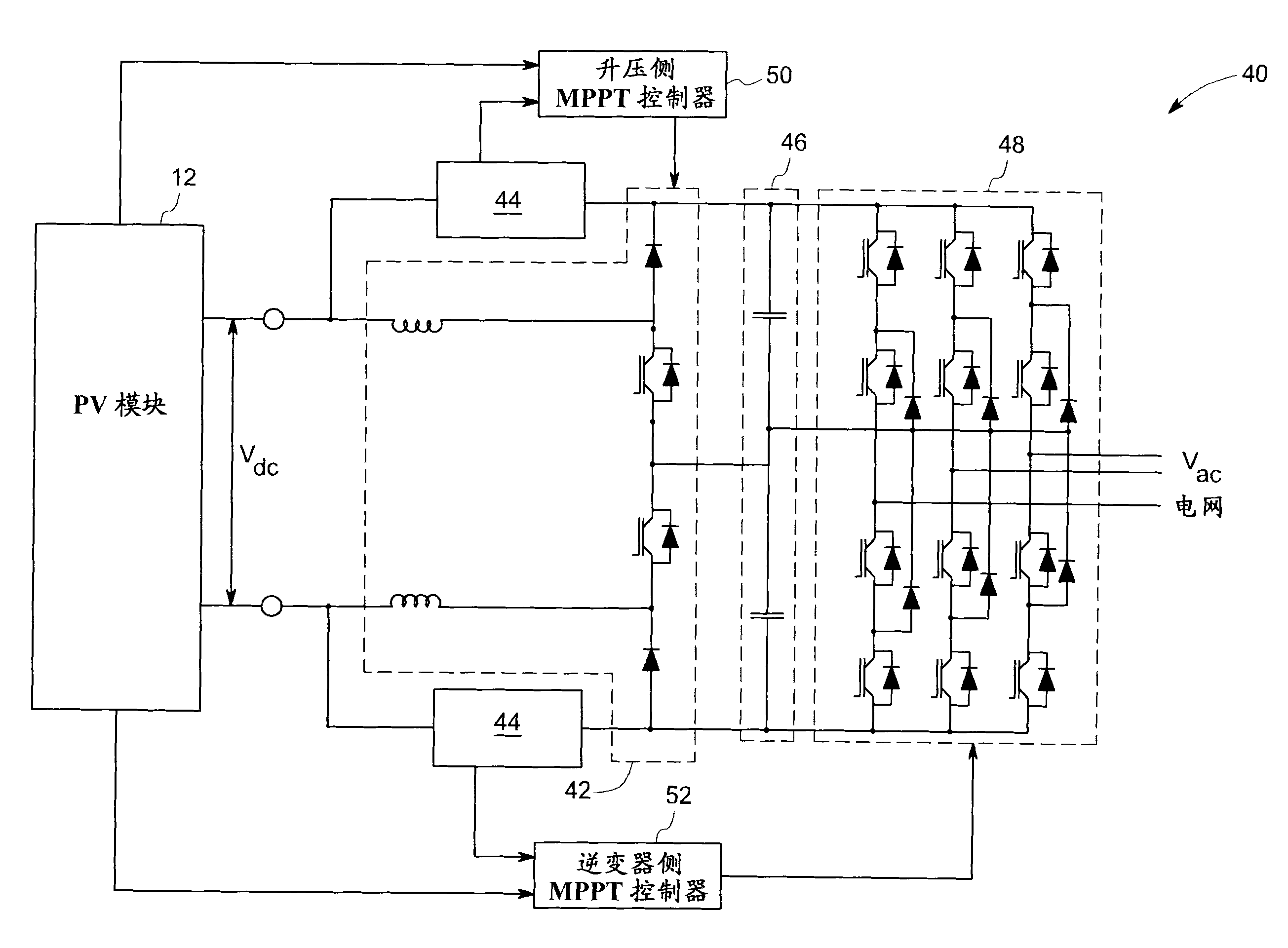
图2示出根据本发明的一实施例的太阳能发电系统40。在一个实施例中,该系统包括PV模块12、升压变换器42、旁路电路44、分开的DC链路46、多电平三相逆变器48、升压侧最大功率点控制器(MPPT)控制器50和逆变器侧MPPT控制器52。电网电压Vac一般地确定最小DC链路电压。只要DC链路电压高于通常由最大峰值线到线电压设置的阈值或阈值电压,则由多电平逆变器48注入到电网中的电流将具有正弦波形。如果PV模块的最大功率点操作与低于阈值电压的电压关联,则使用升压侧MPPT控制器50来确定对于PV模块的电流电压(I-V)特性的最大功率点,以及向升压变换器提供开 关信号以操作模块总是靠近该点。因此,升压变换器用于提升DC链路电压以使它至少等于阈值电压,以便从PV模块提取最大功率。 FIG. 2 shows a solar
在一个实施例中,MPPT控制器50利用扰动和观察方法。在扰动和观察方法中,扰动从太阳能电池阵列汲取的电流,并观察功率变化。如果扰动导致功率的增加,则以相同方向来进行后续扰动,反之亦然。 In one embodiment,
当在最大功率输出的PV模块电压高于将正弦电流注入到电网中所需的阈值电压时,旁路电路44旁路升压变换器。换言之,当光电(PV)模块处的DC电压高于分开的DC链路处的最小电压时,旁路升压变换器。因为太阳能发电系统中的升压变换器对于某个持续时间被旁路,所以它通过对于该持续时间消除升压变换器和升压电感器中的损耗来提高系统的效率。在一个实施例中,旁路电路包括功率二极管或受电压控制的开关。在另一个实施例中,功率二极管包括碳化硅(SiC)二极管来进一步提高太阳能发电系统的效率。在提出的太阳能发电系统的一个实施例中,当旁路电路44旁路升压变换器42时,对多电平逆变器48操作MPPT。逆变器侧MPPT控制器52从PV模块感测电压和电流,并且它还从旁路电路44接收信号以确定电路44何时正在工作。如果旁路升压变换器,则控制器52向多电平逆变器48提供开关命令信号,以便多电平逆变器48将从PV模块提取最大功率。在一个实施例中,可以将控制器50和52组合成单个控制器。
图3示出根据本发明的一实施例的两个电感器升压变换器连同分开的DC链路的示意图60。升压变换器42包括开关装置62、64、升压电感器66、68以及二极管70、72和74。在一个实施例中,开关装置包括绝缘栅极双极晶体管(IGBT)或功率金属氧化物半导体场效应晶体管(MOSFET)。开关装置通常由栅极驱动电路来接通和断开,并且在一个实施例中,其包括碳化硅装置以提高电路的效率。分开的DC链路46包括两个电容器76和78。在操作中,在一个步骤中,接通开关装置62和64,这使得能量被存储在升压电感器66和68中。 在另一个步骤中,当开关装置64仍接通时,开关装置62被断开。此步骤导致通过由升压电感器66、二极管70、电容器76、装置64和升压电感器68形成的充电路径对电容器76充电。在又一个步骤中,当装置62被接通时,开关装置64被断开。这导致通过由升压电感器66、装置62、电容器78、二极管72和升压电感器68形成的充电路径对电容器78充电。当装置62和64均被断开时,可以通过由升压电感器66、二极管70、电容器76、78、二极管72和升压电感器68形成的充电路径对电容器76和78充电。 FIG. 3 shows a schematic diagram 60 of a two inductor boost converter with a split DC link according to an embodiment of the invention.
图4示出根据本发明的一实施例的另一个两个电感器升压变换器和分开的DC链路的示意图90。在图4的实施例中,将单个开关装置92与两个二极管94和96一起使用,而非像图3的实施例中那样使用两个开关装置62和64。在操作中,当装置92被接通时,电流从升压电感器66、装置92和升压电感器68流动。因此,将能量存储在两个电感器中。在此时间期间,二极管70和72分别阻挡电压V1和V2。当装置92被断开时,电流从升压电感器66、二极管70、电容器76和78、二极管72和升压电感器68流动。因此,对电容器76和78充电。 FIG. 4 shows a schematic diagram 90 of another two inductor boost converter and a split DC link according to an embodiment of the invention. In the embodiment of FIG. 4 , a
图5示出根据本发明的一实施例的二极管钳位的多电平逆变器的一个分支或一个相及其输出波形的示意图110。在一个实施例中,多电平逆变器的一个分支112包括四个开关装置114、116、118和120和两个二极管122和124。电压V1和V2由图3或图4的升压变换器42来控制以保持在Vdc/2,并且电压V3是相位A电压。而且,装置114是装置118的互补,即,当装置114正在传导时,装置118不在传导,并且反之亦然。相似地,装置116和120是彼此的互补。 FIG. 5 shows a schematic diagram 110 of a branch or a phase of a diode-clamped multilevel inverter and its output waveforms according to an embodiment of the present invention. In one embodiment, one
在操作中,二极管钳位的多电平逆变器的一个分支具有三个开关级。在第一开关级中,装置114和116被接通,并且装置118和120被断开。假定稳定操作VI=V2=Vdc/2,V3变成Vdc。在第二开关级中,当装置112和120被断开时,装置116和118被接通。在此级中, V3等于Vdc/2。在此级中,输出电压等于多电平变换器的中心抽头(tap)或中心点126处的电压。中心点126是指两个DC链路电容器之间的连接点。在其中有多于两个DC链路电容器的一个实施例中,根据所利用的DC链路电容器的数量,可能有多于一个中心点。在操作中,根据由多电平变换器供应到电力网的负载电流,中心点电压不可保持稳定,并且因此电压V1和V2可从值Vdc/2波动。在一个实施例中,在PV模块的输出电压小于阈值电压时,中心点的稳定性由升压变换器来控制;而在PV模块的输出电压高于阈值电压时,中心点的稳定性由多电平变换器来控制。 In operation, one branch of a diode-clamped multilevel inverter has three switching stages. In a first switching stage,
在第三开关级中,装置114和116被接通,而装置118和120被断开。这导致V3变成零,如波形130中所示。因此,能看到相位电压V3具有三个电平Vdc、Vdc/2和0。然后将二极管钳位的三相逆变器的所有三个分支组合,并且将所得到的线电压(其具有五个电平,即Vdc、Vdc/2、0、-Vdc/2和-Vdc)馈送到电力网,如图2中所示。在另一个实施例(未示出)中,多电平逆变器可以包括快速电容器逆变器,该快速电容器逆变器包括梯形结构的DC电容器或级联的H桥逆变器,其中各个单相逆变器被串联。本领域技术人员将认识到,能根据电路拓扑并由此根据电路中的装置和二极管的数量将图5的三电平逆变器112增加到任何电平。随着逆变器中的电平数量增加,逆变器的输出波形接近纯正弦波,从而导致输出电压中的谐波更低。 In the third switching stage,
多电平逆变器的优点是降低对无源装置(例如电感器)的dv/dt应力,这是因为电压步阶中小的增量、降低的电磁兼容性、开关装置和滤波器组件的更小的额定值以及输出电压在更少的失真、更低的谐波内容和更低的开关损耗方面的更好特征所引起的。 The advantage of multilevel inverters is the reduced dv/dt stress on passive devices (such as inductors) due to small increments in voltage steps, reduced electromagnetic compatibility, tighter switching devices and filter components. Smaller ratings and better characteristics of the output voltage in terms of less distortion, lower harmonic content and lower switching losses. the
虽然本文仅示出并描述了本发明的某些特征,但是本领域技术人员将想到许多修改和改变。因此,要理解所附权利要求旨在涵盖落在本发明真正精神内的所有此类修改和改变。 While only certain features of the invention have been illustrated and described herein, many modifications and changes will occur to those skilled in the art. It is, therefore, to be understood that the appended claims are intended to cover all such modifications and changes as fall within the true spirit of the invention. the
要素列表 element list
10常规太阳能发电系统 10 conventional solar power generation system
12PV阵列 12PV array
14电力网 14 power grid
16DC/DC变换器 16DC/DC Converter
18DC链路 18DC link
20电网侧变换器 20 grid side converter
22DC/DC控制器 22DC/DC controller
24电网侧控制器 24 grid side controller
26系统控制器 26 system controller
40太阳能发电系统 40 solar power generation system
42升压变换器 42 boost converter
44旁路电路 44 bypass circuit
46分开的DC链路 46 separate DC links
48多电平三相逆变器 48 multi-level three-phase inverter
50升压侧最大功率点跟踪(MPPT)控制器 50 boost side maximum power point tracking (MPPT) controller
52逆变器侧MPPT控制器 52 Inverter side MPPT controller
60两个电感器升压变换器的示意图 60 Schematic of a Two Inductor Boost Converter
62,64开关装置 62, 64 switchgear
66,68升压电感器 66, 68 boost inductor
70,72,74二极管 70, 72, 74 diodes
76,78电容器 76, 78 capacitors
90两个电感器升压变换器的示意图 90 Schematic of a two-inductor boost converter
92开关装置 92 switch device
94,96二极管 94, 96 diodes
110包括分开的DC链路的二极管钳位的多电平逆变器的一个分支的示意图 110 Schematic diagram of one branch of a diode-clamped multilevel inverter including separate DC links
112二极管钳位的多电平逆变器的一个分支 A branch of the 112-diode clamped multilevel inverter
114,116,118,120开关装置 114, 116, 118, 120 switchgear
122,124二极管 122, 124 diodes
126中心点 126 center points
130多电平逆变器的一个分支的输出波形。 130 Output waveforms of one branch of the multilevel inverter. the
Claims (10)
Applications Claiming Priority (2)
| Application Number | Priority Date | Filing Date | Title |
|---|---|---|---|
| US12/473,700 US8184460B2 (en) | 2009-05-28 | 2009-05-28 | Solar inverter and control method |
| US12/473700 | 2009-05-28 |
Publications (2)
| Publication Number | Publication Date |
|---|---|
| CN101902145A true CN101902145A (en) | 2010-12-01 |
| CN101902145B CN101902145B (en) | 2016-06-01 |
Family
ID=42289553
Family Applications (1)
| Application Number | Title | Priority Date | Filing Date |
|---|---|---|---|
| CN201010196647.8A Expired - Fee Related CN101902145B (en) | 2009-05-28 | 2010-05-28 | Solar inverter and control method |
Country Status (4)
| Country | Link |
|---|---|
| US (1) | US8184460B2 (en) |
| EP (1) | EP2256579B1 (en) |
| CN (1) | CN101902145B (en) |
| AU (1) | AU2010202078B2 (en) |
Cited By (18)
| Publication number | Priority date | Publication date | Assignee | Title |
|---|---|---|---|---|
| CN102315798A (en) * | 2010-06-29 | 2012-01-11 | 通用电气公司 | Solar power system and method |
| CN103186160A (en) * | 2011-12-31 | 2013-07-03 | 上海亿福新能源技术有限公司 | Self-adjustment control method for maximum power point tracing of photovoltaic power generation |
| WO2014043980A1 (en) * | 2012-09-21 | 2014-03-27 | 纽福克斯光电科技(上海)有限公司 | Circuit for emergency start of motor vehicle |
| CN103875172A (en) * | 2011-07-08 | 2014-06-18 | Sma太阳能技术股份公司 | DC/AC converter, power generation plant and operating method for a DC/AC converter |
| CN104158208A (en) * | 2014-07-15 | 2014-11-19 | 阳光电源股份有限公司 | Single-stage photovoltaic grid-connected inverter, as well as control method and application thereof |
| CN104969139A (en) * | 2013-03-20 | 2015-10-07 | 富士电机株式会社 | Solar power generation system |
| CN105048854A (en) * | 2015-07-21 | 2015-11-11 | 珠海格力电器股份有限公司 | Three-phase non-isolated grid-connected converter and air conditioning system |
| CN105186901A (en) * | 2015-09-06 | 2015-12-23 | 阳光电源股份有限公司 | Input voltage control method and device of five-level inverter |
| CN105340180A (en) * | 2013-03-15 | 2016-02-17 | 先进地球科学股份有限公司 | High power current switch |
| CN105431992A (en) * | 2013-07-23 | 2016-03-23 | 东芝三菱电机产业系统株式会社 | Control device for solar power generation inverter |
| CN105490302A (en) * | 2016-01-22 | 2016-04-13 | 国家电网公司 | Multilevel photovoltaic inversion device without AC/DC current sensor |
| CN105490303A (en) * | 2016-01-22 | 2016-04-13 | 国家电网公司 | A multi-level energy storage power conversion control device without AC and DC current sensors |
| CN105515513A (en) * | 2016-01-29 | 2016-04-20 | 阳光电源股份有限公司 | Photovoltaic inverter and control method thereof |
| CN105531898A (en) * | 2013-07-15 | 2016-04-27 | 普利茅斯大学 | control structure |
| CN105826915A (en) * | 2015-01-23 | 2016-08-03 | 通用电气公司 | Direct current power system |
| CN102545673B (en) * | 2010-12-21 | 2016-08-03 | 通用电气公司 | For operating the method and system of two-stage power conversion device |
| CN107302319A (en) * | 2017-06-14 | 2017-10-27 | 珠海格力电器股份有限公司 | Single-phase sine wave inverter and control method thereof |
| CN107317343A (en) * | 2017-08-24 | 2017-11-03 | 长沙理工大学 | Efficient cascade H bridge types dynamic electric voltage recovery device and its control method |
Families Citing this family (118)
| Publication number | Priority date | Publication date | Assignee | Title |
|---|---|---|---|---|
| US10693415B2 (en) | 2007-12-05 | 2020-06-23 | Solaredge Technologies Ltd. | Testing of a photovoltaic panel |
| US11881814B2 (en) | 2005-12-05 | 2024-01-23 | Solaredge Technologies Ltd. | Testing of a photovoltaic panel |
| US8405367B2 (en) | 2006-01-13 | 2013-03-26 | Enecsys Limited | Power conditioning units |
| GB2454389B (en) | 2006-01-13 | 2009-08-26 | Enecsys Ltd | Power conditioning unit |
| US8473250B2 (en) | 2006-12-06 | 2013-06-25 | Solaredge, Ltd. | Monitoring of distributed power harvesting systems using DC power sources |
| US8013472B2 (en) | 2006-12-06 | 2011-09-06 | Solaredge, Ltd. | Method for distributed power harvesting using DC power sources |
| US8947194B2 (en) | 2009-05-26 | 2015-02-03 | Solaredge Technologies Ltd. | Theft detection and prevention in a power generation system |
| US11569659B2 (en) | 2006-12-06 | 2023-01-31 | Solaredge Technologies Ltd. | Distributed power harvesting systems using DC power sources |
| US11296650B2 (en) | 2006-12-06 | 2022-04-05 | Solaredge Technologies Ltd. | System and method for protection during inverter shutdown in distributed power installations |
| US8319471B2 (en) | 2006-12-06 | 2012-11-27 | Solaredge, Ltd. | Battery power delivery module |
| US11888387B2 (en) | 2006-12-06 | 2024-01-30 | Solaredge Technologies Ltd. | Safety mechanisms, wake up and shutdown methods in distributed power installations |
| US8319483B2 (en) | 2007-08-06 | 2012-11-27 | Solaredge Technologies Ltd. | Digital average input current control in power converter |
| US9088178B2 (en) | 2006-12-06 | 2015-07-21 | Solaredge Technologies Ltd | Distributed power harvesting systems using DC power sources |
| US11309832B2 (en) | 2006-12-06 | 2022-04-19 | Solaredge Technologies Ltd. | Distributed power harvesting systems using DC power sources |
| US8816535B2 (en) * | 2007-10-10 | 2014-08-26 | Solaredge Technologies, Ltd. | System and method for protection during inverter shutdown in distributed power installations |
| US12316274B2 (en) | 2006-12-06 | 2025-05-27 | Solaredge Technologies Ltd. | Pairing of components in a direct current distributed power generation system |
| US11855231B2 (en) | 2006-12-06 | 2023-12-26 | Solaredge Technologies Ltd. | Distributed power harvesting systems using DC power sources |
| US11735910B2 (en) | 2006-12-06 | 2023-08-22 | Solaredge Technologies Ltd. | Distributed power system using direct current power sources |
| US8618692B2 (en) | 2007-12-04 | 2013-12-31 | Solaredge Technologies Ltd. | Distributed power system using direct current power sources |
| US8963369B2 (en) | 2007-12-04 | 2015-02-24 | Solaredge Technologies Ltd. | Distributed power harvesting systems using DC power sources |
| US8384243B2 (en) | 2007-12-04 | 2013-02-26 | Solaredge Technologies Ltd. | Distributed power harvesting systems using DC power sources |
| US9112379B2 (en) | 2006-12-06 | 2015-08-18 | Solaredge Technologies Ltd. | Pairing of components in a direct current distributed power generation system |
| US11687112B2 (en) | 2006-12-06 | 2023-06-27 | Solaredge Technologies Ltd. | Distributed power harvesting systems using DC power sources |
| US9130401B2 (en) | 2006-12-06 | 2015-09-08 | Solaredge Technologies Ltd. | Distributed power harvesting systems using DC power sources |
| EP2232690B1 (en) | 2007-12-05 | 2016-08-31 | Solaredge Technologies Ltd. | Parallel connected inverters |
| JP2011507465A (en) | 2007-12-05 | 2011-03-03 | ソラレッジ テクノロジーズ リミテッド | Safety mechanism, wake-up method and shutdown method in distributed power installation |
| US11264947B2 (en) | 2007-12-05 | 2022-03-01 | Solaredge Technologies Ltd. | Testing of a photovoltaic panel |
| WO2009072076A2 (en) | 2007-12-05 | 2009-06-11 | Solaredge Technologies Ltd. | Current sensing on a mosfet |
| WO2009118683A2 (en) | 2008-03-24 | 2009-10-01 | Solaredge Technolgies Ltd. | Zero voltage switching |
| US9000617B2 (en) | 2008-05-05 | 2015-04-07 | Solaredge Technologies, Ltd. | Direct current power combiner |
| US12418177B2 (en) | 2009-10-24 | 2025-09-16 | Solaredge Technologies Ltd. | Distributed power system using direct current power sources |
| FR2952482B1 (en) * | 2009-11-06 | 2011-11-18 | Mge Ups Systems | CONVERTER DEVICE COMPRISING AT LEAST FIVE LEVELS OF CONTINUOUS VOLTAGE AND NON - INTERRUPTION POWER SUPPLY PROVIDED WITH SAID DEVICE. |
| US8710699B2 (en) | 2009-12-01 | 2014-04-29 | Solaredge Technologies Ltd. | Dual use photovoltaic system |
| KR101094002B1 (en) * | 2009-12-16 | 2011-12-15 | 삼성에스디아이 주식회사 | Power converter |
| US8766696B2 (en) | 2010-01-27 | 2014-07-01 | Solaredge Technologies Ltd. | Fast voltage level shifter circuit |
| US9142960B2 (en) * | 2010-02-03 | 2015-09-22 | Draker, Inc. | Constraint weighted regulation of DC/DC converters |
| WO2011132206A1 (en) * | 2010-04-19 | 2011-10-27 | Power-One Italy S.P.A. | Multi-level dc/ac converter |
| US8390261B2 (en) | 2010-05-21 | 2013-03-05 | Infineon Technologies Austria Ag | Maximum power point tracker bypass |
| KR101106413B1 (en) * | 2010-06-14 | 2012-01-17 | 삼성에스디아이 주식회사 | Inverter of energy storage system |
| EP2410648A1 (en) * | 2010-07-20 | 2012-01-25 | Vincotech Holdings S.a.r.l. | DC/DC converter circuit and method for controlling a DC/DC converter circuit |
| US9350166B2 (en) | 2010-10-05 | 2016-05-24 | Alencon Acquisition Co., Llc | High voltage energy harvesting and conversion renewable energy utility size electric power systems and visual monitoring and control systems for said systems |
| KR20130100161A (en) | 2010-10-05 | 2013-09-09 | 알렌콘 애퀴지션 컴퍼니 엘엘씨 | High voltage energy harvesting and conversion renewable energy utility size electric power systems and visual monitoring and control systems for said systems |
| US10230310B2 (en) | 2016-04-05 | 2019-03-12 | Solaredge Technologies Ltd | Safety switch for photovoltaic systems |
| GB2485527B (en) | 2010-11-09 | 2012-12-19 | Solaredge Technologies Ltd | Arc detection and prevention in a power generation system |
| US10673222B2 (en) | 2010-11-09 | 2020-06-02 | Solaredge Technologies Ltd. | Arc detection and prevention in a power generation system |
| US10673229B2 (en) | 2010-11-09 | 2020-06-02 | Solaredge Technologies Ltd. | Arc detection and prevention in a power generation system |
| GB2486408A (en) | 2010-12-09 | 2012-06-20 | Solaredge Technologies Ltd | Disconnection of a string carrying direct current |
| GB2496140B (en) | 2011-11-01 | 2016-05-04 | Solarcity Corp | Photovoltaic power conditioning units |
| GB2483317B (en) | 2011-01-12 | 2012-08-22 | Solaredge Technologies Ltd | Serially connected inverters |
| GB2487368B (en) | 2011-01-18 | 2012-12-05 | Enecsys Ltd | Inverters |
| FR2976405B1 (en) * | 2011-06-08 | 2014-04-04 | Commissariat Energie Atomique | DEVICE FOR GENERATING PHOTOVOLTAIC ENERGY WITH INDIVIDUAL MANAGEMENT OF CELLS |
| WO2012149387A1 (en) * | 2011-04-27 | 2012-11-01 | Solarbridge Technologies, Inc. | Configurable power supply assembly |
| US8599587B2 (en) | 2011-04-27 | 2013-12-03 | Solarbridge Technologies, Inc. | Modular photovoltaic power supply assembly |
| US12362647B2 (en) | 2011-05-08 | 2025-07-15 | Koolbridge Solar, Inc. | Solar energy system with variable priority circuit backup |
| US11901810B2 (en) | 2011-05-08 | 2024-02-13 | Koolbridge Solar, Inc. | Adaptive electrical power distribution panel |
| US8937822B2 (en) | 2011-05-08 | 2015-01-20 | Paul Wilkinson Dent | Solar energy conversion and utilization system |
| US11460488B2 (en) | 2017-08-14 | 2022-10-04 | Koolbridge Solar, Inc. | AC electrical power measurements |
| US9627889B2 (en) | 2011-05-12 | 2017-04-18 | Alencon Acquisition Co., Llc. | High voltage energy harvesting and conversion renewable energy utility size electric power systems and visual monitoring and control systems |
| US8842397B2 (en) * | 2011-05-23 | 2014-09-23 | Microsemi Corporation | Photo-voltaic safety de-energizing device |
| KR101906895B1 (en) * | 2011-06-08 | 2018-10-11 | 엘에스산전 주식회사 | Photovoltaic power conversion apparatus |
| US8570005B2 (en) | 2011-09-12 | 2013-10-29 | Solaredge Technologies Ltd. | Direct current link circuit |
| WO2013043862A1 (en) * | 2011-09-21 | 2013-03-28 | Enphase Energy, Inc. | Method and apparatus for power module output power regulation |
| US8624411B2 (en) | 2011-10-14 | 2014-01-07 | General Electric Company | Power generation system including predictive control apparatus to reduce influences of weather-varying factors |
| GB2496139B (en) | 2011-11-01 | 2016-05-04 | Solarcity Corp | Photovoltaic power conditioning units |
| CN102403920B (en) * | 2011-11-16 | 2014-05-14 | 广东易事特电源股份有限公司 | Three-level half-bridge photovoltaic grid connected inverter |
| TW201328118A (en) * | 2011-12-28 | 2013-07-01 | Hon Hai Prec Ind Co Ltd | Uninterruptible power supply system |
| GB2498365A (en) | 2012-01-11 | 2013-07-17 | Solaredge Technologies Ltd | Photovoltaic module |
| GB2498791A (en) | 2012-01-30 | 2013-07-31 | Solaredge Technologies Ltd | Photovoltaic panel circuitry |
| GB2498790A (en) | 2012-01-30 | 2013-07-31 | Solaredge Technologies Ltd | Maximising power in a photovoltaic distributed power system |
| US9853565B2 (en) | 2012-01-30 | 2017-12-26 | Solaredge Technologies Ltd. | Maximized power in a photovoltaic distributed power system |
| US20130200709A1 (en) * | 2012-02-03 | 2013-08-08 | International Business Machines Corporation | Techniques for Grid Coupling Photovoltaic Cells Using Ratiometric Voltage Conversion |
| GB2499991A (en) | 2012-03-05 | 2013-09-11 | Solaredge Technologies Ltd | DC link circuit for photovoltaic array |
| US8885373B1 (en) * | 2012-03-07 | 2014-11-11 | Power-One Italy S.pA. | Earth leakage current control for a multi-level grounded inverter |
| US9413268B2 (en) * | 2012-05-10 | 2016-08-09 | Futurewei Technologies, Inc. | Multilevel inverter device and method |
| EP3499695B1 (en) | 2012-05-25 | 2024-09-18 | Solaredge Technologies Ltd. | Circuit for interconnected direct current power sources |
| KR20130133413A (en) * | 2012-05-29 | 2013-12-09 | 엘에스산전 주식회사 | An apparatus for photovoltaic power generation |
| US10115841B2 (en) | 2012-06-04 | 2018-10-30 | Solaredge Technologies Ltd. | Integrated photovoltaic panel circuitry |
| US20140049998A1 (en) * | 2012-08-16 | 2014-02-20 | Leo F. Casey | DC to AC Power Converter |
| US20140070614A1 (en) * | 2012-09-07 | 2014-03-13 | Atomic Energy Council-Institute Of Nuclear Energy Research | Household Grid-Connected Inverter Applied to Solar Power Generation System with Maximum Power Tracking Function |
| BR112015005896A2 (en) | 2012-09-18 | 2017-07-04 | Ge Energy Power Conversion Technology Ltd | energy conversion apparatus and insulation method |
| US9557758B2 (en) * | 2012-10-16 | 2017-01-31 | Volterra Semiconductor LLC | Systems and methods for controlling maximum power point tracking controllers |
| US9548619B2 (en) | 2013-03-14 | 2017-01-17 | Solaredge Technologies Ltd. | Method and apparatus for storing and depleting energy |
| US9941813B2 (en) | 2013-03-14 | 2018-04-10 | Solaredge Technologies Ltd. | High frequency multi-level inverter |
| EP3506370B1 (en) | 2013-03-15 | 2023-12-20 | Solaredge Technologies Ltd. | Bypass mechanism |
| US9634560B2 (en) | 2013-03-26 | 2017-04-25 | Telefonaktiebolaget Lm Ericsson (Publ) | Voltage modulator |
| US9071150B2 (en) * | 2013-05-07 | 2015-06-30 | University Of Central Florida Research Foundation, Inc. | Variable frequency iteration MPPT for resonant power converters |
| US9270164B2 (en) | 2013-06-19 | 2016-02-23 | Tmeic Corporation | Methods, systems, computer program products, and devices for renewable energy site power limit control |
| US9647571B2 (en) * | 2013-08-02 | 2017-05-09 | Solantro Semiconductor Corp. | Internal inverter communications |
| US9337748B2 (en) * | 2013-08-02 | 2016-05-10 | Infineon Technologies Austria Ag | System and method for a DC-to-DC power converter with inverter stage coupled to the DC input |
| KR101741075B1 (en) * | 2013-09-02 | 2017-05-29 | 엘에스산전 주식회사 | Photovoltaic inverter |
| US9728974B2 (en) | 2013-10-10 | 2017-08-08 | Tmeic Corporation | Renewable energy site reactive power control |
| ITBZ20130050A1 (en) * | 2013-10-10 | 2015-04-11 | Sunforlife S R L | OPTIMIZER FOR PHOTOVOLTAIC STRINGS, THROUGH THE INNOVATIVE METHOD OF SHARING THE CHARGE THAT ACTIVATES IN PARALLEL WITH THE STRINGS OR ITS PRESERVING THE ORIGINAL SERIES CONNECTION |
| EP3061174B1 (en) | 2013-10-21 | 2018-04-25 | ABB Schweiz AG | Double-stage inverter apparatus for energy conversion systems and control method thereof |
| US9318974B2 (en) | 2014-03-26 | 2016-04-19 | Solaredge Technologies Ltd. | Multi-level inverter with flying capacitor topology |
| US9555711B2 (en) * | 2014-06-03 | 2017-01-31 | Hamilton Sundstrand Corporation | Power converters |
| CN104038036B (en) * | 2014-06-30 | 2016-08-24 | 阳光电源股份有限公司 | Suspended voltage suppressing method, device, inverter control system and inverter thereof |
| CN104269914A (en) * | 2014-10-15 | 2015-01-07 | 四川东方电气自动控制工程有限公司 | Wind-solar complementary control and inversion integrated machine |
| CN104377977A (en) * | 2014-12-08 | 2015-02-25 | 国家电网公司 | Three-level converter and control method thereof |
| US9806601B2 (en) * | 2015-03-27 | 2017-10-31 | Futurewei Technologies, Inc. | Boost converter and method |
| GB201513549D0 (en) * | 2015-07-31 | 2015-09-16 | Siemens Ag | Inverter |
| US10938218B2 (en) | 2015-12-28 | 2021-03-02 | Sunpower Corporation | Solar tracker system |
| US10599113B2 (en) | 2016-03-03 | 2020-03-24 | Solaredge Technologies Ltd. | Apparatus and method for determining an order of power devices in power generation systems |
| CN117130027A (en) | 2016-03-03 | 2023-11-28 | 太阳能安吉科技有限公司 | Methods for mapping power generation facilities |
| US11081608B2 (en) | 2016-03-03 | 2021-08-03 | Solaredge Technologies Ltd. | Apparatus and method for determining an order of power devices in power generation systems |
| US12057807B2 (en) | 2016-04-05 | 2024-08-06 | Solaredge Technologies Ltd. | Chain of power devices |
| US11018623B2 (en) | 2016-04-05 | 2021-05-25 | Solaredge Technologies Ltd. | Safety switch for photovoltaic systems |
| US11177663B2 (en) | 2016-04-05 | 2021-11-16 | Solaredge Technologies Ltd. | Chain of power devices |
| US10483759B2 (en) | 2016-04-07 | 2019-11-19 | Alencon Acquisition Co., Llc | Integrated multi-mode large-scale electric power support system for an electrical grid |
| US10236690B2 (en) | 2016-06-30 | 2019-03-19 | Sunpower Corporation | Backfeed power supply for solar power system |
| JP6952245B2 (en) * | 2016-09-30 | 2021-10-20 | パナソニックIpマネジメント株式会社 | Power conversion system |
| CN110350812B (en) * | 2018-04-08 | 2024-08-13 | 佛山科学技术学院 | An inverter module for UPS |
| US10516365B1 (en) | 2018-06-20 | 2019-12-24 | Schneider Electric Solar Inverters Usa, Inc. | DC voltage control in renewable energy based multilevel power converter |
| FR3084798B1 (en) * | 2018-08-03 | 2020-10-30 | Schneider Electric Ind Sas | MULTI-LEVEL POWER CONVERTER |
| US10651739B1 (en) | 2019-02-25 | 2020-05-12 | Nextracker Inc. | Power converters and methods of controlling same |
| CN110994975B (en) * | 2019-12-18 | 2020-11-10 | 阳光电源股份有限公司 | Capacitor clamp type direct current conversion circuit |
| CN114223127B (en) | 2020-07-07 | 2024-04-09 | 华为数字能源技术有限公司 | A power supply system |
| CN112234649A (en) * | 2020-10-15 | 2021-01-15 | 珠海格力电器股份有限公司 | Adaptive photovoltaic power supply system and control method thereof, and air conditioning unit |
| US11811318B2 (en) | 2020-11-03 | 2023-11-07 | Solaredge Technologies Ltd. | Method and apparatus for power conversion |
Citations (3)
| Publication number | Priority date | Publication date | Assignee | Title |
|---|---|---|---|---|
| US20060174939A1 (en) * | 2004-12-29 | 2006-08-10 | Isg Technologies Llc | Efficiency booster circuit and technique for maximizing power point tracking |
| CN101350569A (en) * | 2008-09-03 | 2009-01-21 | 深圳职业技术学院 | Solar PV Inverter Topology |
| CN101436833A (en) * | 2007-11-14 | 2009-05-20 | 通用电气公司 | Method and system to convert direct current (DC) to alternating current (AC) using a photovoltaic inverter |
Family Cites Families (15)
| Publication number | Priority date | Publication date | Assignee | Title |
|---|---|---|---|---|
| US5389158A (en) | 1989-04-17 | 1995-02-14 | The Boeing Company | Low bandgap photovoltaic cell with inherent bypass diode |
| US5179508A (en) | 1991-10-15 | 1993-01-12 | International Business Machines Corp. | Standby boost converter |
| US6111767A (en) * | 1998-06-22 | 2000-08-29 | Heliotronics, Inc. | Inverter integrated instrumentation having a current-voltage curve tracer |
| AUPS143902A0 (en) * | 2002-03-28 | 2002-05-09 | Curtin University Of Technology | Power conversion system and method of converting power |
| US7227278B2 (en) * | 2004-01-21 | 2007-06-05 | Nextek Power Systems Inc. | Multiple bi-directional input/output power control system |
| JP4527767B2 (en) | 2005-02-25 | 2010-08-18 | 三菱電機株式会社 | Power converter |
| US8013472B2 (en) | 2006-12-06 | 2011-09-06 | Solaredge, Ltd. | Method for distributed power harvesting using DC power sources |
| GB0625121D0 (en) * | 2006-12-18 | 2007-01-24 | Gendrive Ltd | Electrical energy converter |
| US7772716B2 (en) | 2007-03-27 | 2010-08-10 | Newdoll Enterprises Llc | Distributed maximum power point tracking system, structure and process |
| US20090000654A1 (en) * | 2007-05-17 | 2009-01-01 | Larankelo, Inc. | Distributed inverter and intelligent gateway |
| US20090014050A1 (en) | 2007-07-13 | 2009-01-15 | Peter Haaf | Solar module system and method using transistors for bypass |
| EP2104200B1 (en) | 2008-03-22 | 2019-02-27 | SMA Solar Technology AG | Method for controlling a multi-string inverter for photovoltaic systems |
| US8334616B2 (en) * | 2008-09-19 | 2012-12-18 | Electric Power Research Institute, Inc. | Photovoltaic integrated variable frequency drive |
| US20100157632A1 (en) * | 2008-12-20 | 2010-06-24 | Azuray Technologies, Inc. | Energy Conversion Systems With Power Control |
| US8400134B2 (en) * | 2009-11-12 | 2013-03-19 | Intersil Americas Inc. | Apparatus and methodology for maximum power point tracking for a solar panel |
-
2009
- 2009-05-28 US US12/473,700 patent/US8184460B2/en active Active
-
2010
- 2010-05-19 EP EP10163331.1A patent/EP2256579B1/en active Active
- 2010-05-21 AU AU2010202078A patent/AU2010202078B2/en active Active
- 2010-05-28 CN CN201010196647.8A patent/CN101902145B/en not_active Expired - Fee Related
Patent Citations (3)
| Publication number | Priority date | Publication date | Assignee | Title |
|---|---|---|---|---|
| US20060174939A1 (en) * | 2004-12-29 | 2006-08-10 | Isg Technologies Llc | Efficiency booster circuit and technique for maximizing power point tracking |
| CN101436833A (en) * | 2007-11-14 | 2009-05-20 | 通用电气公司 | Method and system to convert direct current (DC) to alternating current (AC) using a photovoltaic inverter |
| CN101350569A (en) * | 2008-09-03 | 2009-01-21 | 深圳职业技术学院 | Solar PV Inverter Topology |
Cited By (27)
| Publication number | Priority date | Publication date | Assignee | Title |
|---|---|---|---|---|
| CN102315798A (en) * | 2010-06-29 | 2012-01-11 | 通用电气公司 | Solar power system and method |
| CN102545673B (en) * | 2010-12-21 | 2016-08-03 | 通用电气公司 | For operating the method and system of two-stage power conversion device |
| CN103875172A (en) * | 2011-07-08 | 2014-06-18 | Sma太阳能技术股份公司 | DC/AC converter, power generation plant and operating method for a DC/AC converter |
| CN103875172B (en) * | 2011-07-08 | 2017-02-22 | Sma太阳能技术股份公司 | DC/AC converter, power generation plant and operating method for DC/AC converter |
| CN103186160A (en) * | 2011-12-31 | 2013-07-03 | 上海亿福新能源技术有限公司 | Self-adjustment control method for maximum power point tracing of photovoltaic power generation |
| CN103186160B (en) * | 2011-12-31 | 2015-02-11 | 上海亿福新能源技术有限公司 | Self-adjustment control method for maximum power point tracing of photovoltaic power generation |
| WO2014043980A1 (en) * | 2012-09-21 | 2014-03-27 | 纽福克斯光电科技(上海)有限公司 | Circuit for emergency start of motor vehicle |
| CN105340180A (en) * | 2013-03-15 | 2016-02-17 | 先进地球科学股份有限公司 | High power current switch |
| CN105340180B (en) * | 2013-03-15 | 2019-01-29 | 先进地球科学股份有限公司 | High Power Current Switch |
| CN104969139A (en) * | 2013-03-20 | 2015-10-07 | 富士电机株式会社 | Solar power generation system |
| CN104969139B (en) * | 2013-03-20 | 2016-10-05 | 富士电机株式会社 | The Sun can generate system |
| CN105531898A (en) * | 2013-07-15 | 2016-04-27 | 普利茅斯大学 | control structure |
| CN105431992B (en) * | 2013-07-23 | 2019-01-15 | 东芝三菱电机产业系统株式会社 | The control device of solar power generation inverter |
| CN105431992A (en) * | 2013-07-23 | 2016-03-23 | 东芝三菱电机产业系统株式会社 | Control device for solar power generation inverter |
| CN104158208A (en) * | 2014-07-15 | 2014-11-19 | 阳光电源股份有限公司 | Single-stage photovoltaic grid-connected inverter, as well as control method and application thereof |
| CN105826915A (en) * | 2015-01-23 | 2016-08-03 | 通用电气公司 | Direct current power system |
| CN105048854A (en) * | 2015-07-21 | 2015-11-11 | 珠海格力电器股份有限公司 | Three-phase non-isolated grid-connected converter and air conditioning system |
| CN105186901A (en) * | 2015-09-06 | 2015-12-23 | 阳光电源股份有限公司 | Input voltage control method and device of five-level inverter |
| CN105186901B (en) * | 2015-09-06 | 2017-10-27 | 阳光电源股份有限公司 | A kind of five-electrical level inverter input voltage control method and device |
| CN105490302B (en) * | 2016-01-22 | 2018-03-13 | 国家电网公司 | A kind of more level photovoltaic inverters without alterating and direct current flow sensor |
| CN105490303B (en) * | 2016-01-22 | 2018-10-16 | 国家电网公司 | Multi-level energy storage power conversion control device without AC/DC current sensor |
| CN105490303A (en) * | 2016-01-22 | 2016-04-13 | 国家电网公司 | A multi-level energy storage power conversion control device without AC and DC current sensors |
| CN105490302A (en) * | 2016-01-22 | 2016-04-13 | 国家电网公司 | Multilevel photovoltaic inversion device without AC/DC current sensor |
| CN105515513A (en) * | 2016-01-29 | 2016-04-20 | 阳光电源股份有限公司 | Photovoltaic inverter and control method thereof |
| CN107302319A (en) * | 2017-06-14 | 2017-10-27 | 珠海格力电器股份有限公司 | Single-phase sine wave inverter and control method thereof |
| CN107317343A (en) * | 2017-08-24 | 2017-11-03 | 长沙理工大学 | Efficient cascade H bridge types dynamic electric voltage recovery device and its control method |
| CN107317343B (en) * | 2017-08-24 | 2023-05-12 | 长沙理工大学 | High-efficiency cascade H-bridge type dynamic voltage restorer and control method thereof |
Also Published As
| Publication number | Publication date |
|---|---|
| US8184460B2 (en) | 2012-05-22 |
| US20100302819A1 (en) | 2010-12-02 |
| EP2256579B1 (en) | 2017-09-27 |
| AU2010202078A1 (en) | 2010-12-16 |
| AU2010202078B2 (en) | 2015-07-23 |
| EP2256579A1 (en) | 2010-12-01 |
| CN101902145B (en) | 2016-06-01 |
Similar Documents
| Publication | Publication Date | Title |
|---|---|---|
| CN101902145B (en) | Solar inverter and control method | |
| US8144490B2 (en) | Operation of a three level converter | |
| Jana et al. | A review of inverter topologies for single-phase grid-connected photovoltaic systems | |
| Nguyen et al. | A single-phase single-stage switched-boost inverter with four switches | |
| US9559611B2 (en) | Multilevel power converter system and method | |
| US9479075B2 (en) | Multilevel converter system | |
| US9344005B2 (en) | Method and apparatus for producing three-phase current | |
| CN105247776B (en) | Five-level photovoltaic inverter based on multi-state switching unit | |
| US20040165408A1 (en) | Dc to ac inverter with single-switch bipolar boost circuit | |
| EP2924867B1 (en) | Multilevel converter | |
| CN106031010A (en) | Multilevel inverter apparatus and method of operation | |
| Nguyen et al. | DC-link quasi-switched boost inverter with improved PWM strategy and its comparative evaluation | |
| Ding et al. | A new current source converter using AC-type flying-capacitor technique | |
| Parimalasundar et al. | Performance analysis of a seven-level multilevel inverter in grid-connected systems | |
| Charan et al. | A single-phase cascaded H-bridge multilevel inverter with voltage boost ability: Modulation and analysis | |
| EP2993777B1 (en) | Multilevel converter | |
| Ravitheja et al. | A four switch common ground-based single phase current-fed boost inverter | |
| US9325273B2 (en) | Method and system for driving electric machines | |
| Poliseno et al. | High efficiency transformerless PV power converters | |
| Xing et al. | Transformerless Series-Connected Current-Source Converter With Less Switch Count | |
| Muthukaruppasamy et al. | A symmetric multi-level cascaded H-bridge inverter for renewable energy integration | |
| Maheswari et al. | A novel seven-level triple-boost inverter for grid-integrated photovoltaic systems | |
| Maheswari et al. | A novel two five-level double-boost inverters for grid-tied photovoltaic applications | |
| Khawaja | PWM Control Scheme for Quasi-Switched-Boost Inverter to Improve Modulation Index | |
| Esfandiari et al. | Analyzing the On-State Power Dissipation in Stepped-Output Diode-Clamped Multi-Level Inverter |
Legal Events
| Date | Code | Title | Description |
|---|---|---|---|
| C06 | Publication | ||
| PB01 | Publication | ||
| C10 | Entry into substantive examination | ||
| SE01 | Entry into force of request for substantive examination | ||
| C14 | Grant of patent or utility model | ||
| GR01 | Patent grant | ||
| TR01 | Transfer of patent right |
Effective date of registration: 20240328 Address after: American Georgia Patentee after: General Electric Grid Solutions LLC Country or region after: U.S.A. Address before: New York, United States Patentee before: General Electric Co. Country or region before: U.S.A. |
|
| TR01 | Transfer of patent right | ||
| CF01 | Termination of patent right due to non-payment of annual fee |
Granted publication date: 20160601 |
|
| CF01 | Termination of patent right due to non-payment of annual fee |