CN101887935A - Doped elongated semiconductors, their growth, devices containing such semiconductors and their manufacture - Google Patents
Doped elongated semiconductors, their growth, devices containing such semiconductors and their manufacture Download PDFInfo
- Publication number
- CN101887935A CN101887935A CN2010102067826A CN201010206782A CN101887935A CN 101887935 A CN101887935 A CN 101887935A CN 2010102067826 A CN2010102067826 A CN 2010102067826A CN 201010206782 A CN201010206782 A CN 201010206782A CN 101887935 A CN101887935 A CN 101887935A
- Authority
- CN
- China
- Prior art keywords
- semiconductor
- doped
- nanometers
- nanowires
- less
- Prior art date
- Legal status (The legal status is an assumption and is not a legal conclusion. Google has not performed a legal analysis and makes no representation as to the accuracy of the status listed.)
- Granted
Links
Images


Classifications
-
- H—ELECTRICITY
- H10—SEMICONDUCTOR DEVICES; ELECTRIC SOLID-STATE DEVICES NOT OTHERWISE PROVIDED FOR
- H10D—INORGANIC ELECTRIC SEMICONDUCTOR DEVICES
- H10D62/00—Semiconductor bodies, or regions thereof, of devices having potential barriers
- H10D62/10—Shapes, relative sizes or dispositions of the regions of the semiconductor bodies; Shapes of the semiconductor bodies
- H10D62/117—Shapes of semiconductor bodies
- H10D62/118—Nanostructure semiconductor bodies
-
- H10P10/00—
-
- B—PERFORMING OPERATIONS; TRANSPORTING
- B01—PHYSICAL OR CHEMICAL PROCESSES OR APPARATUS IN GENERAL
- B01J—CHEMICAL OR PHYSICAL PROCESSES, e.g. CATALYSIS OR COLLOID CHEMISTRY; THEIR RELEVANT APPARATUS
- B01J23/00—Catalysts comprising metals or metal oxides or hydroxides, not provided for in group B01J21/00
- B01J23/38—Catalysts comprising metals or metal oxides or hydroxides, not provided for in group B01J21/00 of noble metals
- B01J23/48—Silver or gold
- B01J23/50—Silver
-
- B—PERFORMING OPERATIONS; TRANSPORTING
- B01—PHYSICAL OR CHEMICAL PROCESSES OR APPARATUS IN GENERAL
- B01J—CHEMICAL OR PHYSICAL PROCESSES, e.g. CATALYSIS OR COLLOID CHEMISTRY; THEIR RELEVANT APPARATUS
- B01J23/00—Catalysts comprising metals or metal oxides or hydroxides, not provided for in group B01J21/00
- B01J23/38—Catalysts comprising metals or metal oxides or hydroxides, not provided for in group B01J21/00 of noble metals
- B01J23/48—Silver or gold
- B01J23/52—Gold
-
- B—PERFORMING OPERATIONS; TRANSPORTING
- B01—PHYSICAL OR CHEMICAL PROCESSES OR APPARATUS IN GENERAL
- B01J—CHEMICAL OR PHYSICAL PROCESSES, e.g. CATALYSIS OR COLLOID CHEMISTRY; THEIR RELEVANT APPARATUS
- B01J23/00—Catalysts comprising metals or metal oxides or hydroxides, not provided for in group B01J21/00
- B01J23/70—Catalysts comprising metals or metal oxides or hydroxides, not provided for in group B01J21/00 of the iron group metals or copper
- B01J23/72—Copper
-
- B—PERFORMING OPERATIONS; TRANSPORTING
- B01—PHYSICAL OR CHEMICAL PROCESSES OR APPARATUS IN GENERAL
- B01J—CHEMICAL OR PHYSICAL PROCESSES, e.g. CATALYSIS OR COLLOID CHEMISTRY; THEIR RELEVANT APPARATUS
- B01J35/00—Catalysts, in general, characterised by their form or physical properties
- B01J35/40—Catalysts, in general, characterised by their form or physical properties characterised by dimensions, e.g. grain size
- B01J35/45—Nanoparticles
-
- B—PERFORMING OPERATIONS; TRANSPORTING
- B01—PHYSICAL OR CHEMICAL PROCESSES OR APPARATUS IN GENERAL
- B01J—CHEMICAL OR PHYSICAL PROCESSES, e.g. CATALYSIS OR COLLOID CHEMISTRY; THEIR RELEVANT APPARATUS
- B01J37/00—Processes, in general, for preparing catalysts; Processes, in general, for activation of catalysts
- B01J37/34—Irradiation by, or application of, electric, magnetic or wave energy, e.g. ultrasonic waves ; Ionic sputtering; Flame or plasma spraying; Particle radiation
- B01J37/349—Irradiation by, or application of, electric, magnetic or wave energy, e.g. ultrasonic waves ; Ionic sputtering; Flame or plasma spraying; Particle radiation making use of flames, plasmas or lasers
-
- B—PERFORMING OPERATIONS; TRANSPORTING
- B81—MICROSTRUCTURAL TECHNOLOGY
- B81C—PROCESSES OR APPARATUS SPECIALLY ADAPTED FOR THE MANUFACTURE OR TREATMENT OF MICROSTRUCTURAL DEVICES OR SYSTEMS
- B81C1/00—Manufacture or treatment of devices or systems in or on a substrate
- B81C1/00015—Manufacture or treatment of devices or systems in or on a substrate for manufacturing microsystems
- B81C1/00134—Manufacture or treatment of devices or systems in or on a substrate for manufacturing microsystems comprising flexible or deformable structures
- B81C1/0019—Flexible or deformable structures not provided for in groups B81C1/00142 - B81C1/00182
-
- B—PERFORMING OPERATIONS; TRANSPORTING
- B81—MICROSTRUCTURAL TECHNOLOGY
- B81C—PROCESSES OR APPARATUS SPECIALLY ADAPTED FOR THE MANUFACTURE OR TREATMENT OF MICROSTRUCTURAL DEVICES OR SYSTEMS
- B81C1/00—Manufacture or treatment of devices or systems in or on a substrate
- B81C1/00015—Manufacture or treatment of devices or systems in or on a substrate for manufacturing microsystems
- B81C1/00206—Processes for functionalising a surface, e.g. provide the surface with specific mechanical, chemical or biological properties
-
- B—PERFORMING OPERATIONS; TRANSPORTING
- B82—NANOTECHNOLOGY
- B82Y—SPECIFIC USES OR APPLICATIONS OF NANOSTRUCTURES; MEASUREMENT OR ANALYSIS OF NANOSTRUCTURES; MANUFACTURE OR TREATMENT OF NANOSTRUCTURES
- B82Y10/00—Nanotechnology for information processing, storage or transmission, e.g. quantum computing or single electron logic
-
- C—CHEMISTRY; METALLURGY
- C30—CRYSTAL GROWTH
- C30B—SINGLE-CRYSTAL GROWTH; UNIDIRECTIONAL SOLIDIFICATION OF EUTECTIC MATERIAL OR UNIDIRECTIONAL DEMIXING OF EUTECTOID MATERIAL; REFINING BY ZONE-MELTING OF MATERIAL; PRODUCTION OF A HOMOGENEOUS POLYCRYSTALLINE MATERIAL WITH DEFINED STRUCTURE; SINGLE CRYSTALS OR HOMOGENEOUS POLYCRYSTALLINE MATERIAL WITH DEFINED STRUCTURE; AFTER-TREATMENT OF SINGLE CRYSTALS OR A HOMOGENEOUS POLYCRYSTALLINE MATERIAL WITH DEFINED STRUCTURE; APPARATUS THEREFOR
- C30B11/00—Single-crystal growth by normal freezing or freezing under temperature gradient, e.g. Bridgman-Stockbarger method
-
- C—CHEMISTRY; METALLURGY
- C30—CRYSTAL GROWTH
- C30B—SINGLE-CRYSTAL GROWTH; UNIDIRECTIONAL SOLIDIFICATION OF EUTECTIC MATERIAL OR UNIDIRECTIONAL DEMIXING OF EUTECTOID MATERIAL; REFINING BY ZONE-MELTING OF MATERIAL; PRODUCTION OF A HOMOGENEOUS POLYCRYSTALLINE MATERIAL WITH DEFINED STRUCTURE; SINGLE CRYSTALS OR HOMOGENEOUS POLYCRYSTALLINE MATERIAL WITH DEFINED STRUCTURE; AFTER-TREATMENT OF SINGLE CRYSTALS OR A HOMOGENEOUS POLYCRYSTALLINE MATERIAL WITH DEFINED STRUCTURE; APPARATUS THEREFOR
- C30B25/00—Single-crystal growth by chemical reaction of reactive gases, e.g. chemical vapour-deposition growth
- C30B25/005—Growth of whiskers or needles
-
- C—CHEMISTRY; METALLURGY
- C30—CRYSTAL GROWTH
- C30B—SINGLE-CRYSTAL GROWTH; UNIDIRECTIONAL SOLIDIFICATION OF EUTECTIC MATERIAL OR UNIDIRECTIONAL DEMIXING OF EUTECTOID MATERIAL; REFINING BY ZONE-MELTING OF MATERIAL; PRODUCTION OF A HOMOGENEOUS POLYCRYSTALLINE MATERIAL WITH DEFINED STRUCTURE; SINGLE CRYSTALS OR HOMOGENEOUS POLYCRYSTALLINE MATERIAL WITH DEFINED STRUCTURE; AFTER-TREATMENT OF SINGLE CRYSTALS OR A HOMOGENEOUS POLYCRYSTALLINE MATERIAL WITH DEFINED STRUCTURE; APPARATUS THEREFOR
- C30B29/00—Single crystals or homogeneous polycrystalline material with defined structure characterised by the material or by their shape
- C30B29/60—Single crystals or homogeneous polycrystalline material with defined structure characterised by the material or by their shape characterised by shape
- C30B29/605—Products containing multiple oriented crystallites, e.g. columnar crystallites
-
- G—PHYSICS
- G01—MEASURING; TESTING
- G01N—INVESTIGATING OR ANALYSING MATERIALS BY DETERMINING THEIR CHEMICAL OR PHYSICAL PROPERTIES
- G01N27/00—Investigating or analysing materials by the use of electric, electrochemical, or magnetic means
- G01N27/26—Investigating or analysing materials by the use of electric, electrochemical, or magnetic means by investigating electrochemical variables; by using electrolysis or electrophoresis
- G01N27/403—Cells and electrode assemblies
- G01N27/414—Ion-sensitive or chemical field-effect transistors, i.e. ISFETS or CHEMFETS
- G01N27/4146—Ion-sensitive or chemical field-effect transistors, i.e. ISFETS or CHEMFETS involving nanosized elements, e.g. nanotubes, nanowires
-
- G—PHYSICS
- G01—MEASURING; TESTING
- G01N—INVESTIGATING OR ANALYSING MATERIALS BY DETERMINING THEIR CHEMICAL OR PHYSICAL PROPERTIES
- G01N33/00—Investigating or analysing materials by specific methods not covered by groups G01N1/00 - G01N31/00
- G01N33/48—Biological material, e.g. blood, urine; Haemocytometers
- G01N33/50—Chemical analysis of biological material, e.g. blood, urine; Testing involving biospecific ligand binding methods; Immunological testing
- G01N33/53—Immunoassay; Biospecific binding assay; Materials therefor
- G01N33/543—Immunoassay; Biospecific binding assay; Materials therefor with an insoluble carrier for immobilising immunochemicals
- G01N33/54366—Apparatus specially adapted for solid-phase testing
- G01N33/54373—Apparatus specially adapted for solid-phase testing involving physiochemical end-point determination, e.g. wave-guides, FETS, gratings
-
- G—PHYSICS
- G11—INFORMATION STORAGE
- G11C—STATIC STORES
- G11C13/00—Digital stores characterised by the use of storage elements not covered by groups G11C11/00, G11C23/00, or G11C25/00
- G11C13/0002—Digital stores characterised by the use of storage elements not covered by groups G11C11/00, G11C23/00, or G11C25/00 using resistive RAM [RRAM] elements
- G11C13/0009—RRAM elements whose operation depends upon chemical change
- G11C13/0014—RRAM elements whose operation depends upon chemical change comprising cells based on organic memory material
- G11C13/0019—RRAM elements whose operation depends upon chemical change comprising cells based on organic memory material comprising bio-molecules
-
- G—PHYSICS
- G11—INFORMATION STORAGE
- G11C—STATIC STORES
- G11C13/00—Digital stores characterised by the use of storage elements not covered by groups G11C11/00, G11C23/00, or G11C25/00
- G11C13/02—Digital stores characterised by the use of storage elements not covered by groups G11C11/00, G11C23/00, or G11C25/00 using elements whose operation depends upon chemical change
- G11C13/025—Digital stores characterised by the use of storage elements not covered by groups G11C11/00, G11C23/00, or G11C25/00 using elements whose operation depends upon chemical change using fullerenes, e.g. C60, or nanotubes, e.g. carbon or silicon nanotubes
-
- H—ELECTRICITY
- H10—SEMICONDUCTOR DEVICES; ELECTRIC SOLID-STATE DEVICES NOT OTHERWISE PROVIDED FOR
- H10D—INORGANIC ELECTRIC SEMICONDUCTOR DEVICES
- H10D62/00—Semiconductor bodies, or regions thereof, of devices having potential barriers
- H10D62/10—Shapes, relative sizes or dispositions of the regions of the semiconductor bodies; Shapes of the semiconductor bodies
- H10D62/117—Shapes of semiconductor bodies
- H10D62/118—Nanostructure semiconductor bodies
- H10D62/119—Nanowire, nanosheet or nanotube semiconductor bodies
- H10D62/121—Nanowire, nanosheet or nanotube semiconductor bodies oriented parallel to substrates
-
- H—ELECTRICITY
- H10—SEMICONDUCTOR DEVICES; ELECTRIC SOLID-STATE DEVICES NOT OTHERWISE PROVIDED FOR
- H10D—INORGANIC ELECTRIC SEMICONDUCTOR DEVICES
- H10D62/00—Semiconductor bodies, or regions thereof, of devices having potential barriers
- H10D62/10—Shapes, relative sizes or dispositions of the regions of the semiconductor bodies; Shapes of the semiconductor bodies
- H10D62/117—Shapes of semiconductor bodies
- H10D62/118—Nanostructure semiconductor bodies
- H10D62/119—Nanowire, nanosheet or nanotube semiconductor bodies
- H10D62/123—Nanowire, nanosheet or nanotube semiconductor bodies comprising junctions
-
- H—ELECTRICITY
- H10—SEMICONDUCTOR DEVICES; ELECTRIC SOLID-STATE DEVICES NOT OTHERWISE PROVIDED FOR
- H10D—INORGANIC ELECTRIC SEMICONDUCTOR DEVICES
- H10D62/00—Semiconductor bodies, or regions thereof, of devices having potential barriers
- H10D62/40—Crystalline structures
- H10D62/405—Orientations of crystalline planes
-
- H—ELECTRICITY
- H10—SEMICONDUCTOR DEVICES; ELECTRIC SOLID-STATE DEVICES NOT OTHERWISE PROVIDED FOR
- H10D—INORGANIC ELECTRIC SEMICONDUCTOR DEVICES
- H10D62/00—Semiconductor bodies, or regions thereof, of devices having potential barriers
- H10D62/80—Semiconductor bodies, or regions thereof, of devices having potential barriers characterised by the materials
- H10D62/82—Heterojunctions
-
- H—ELECTRICITY
- H10—SEMICONDUCTOR DEVICES; ELECTRIC SOLID-STATE DEVICES NOT OTHERWISE PROVIDED FOR
- H10D—INORGANIC ELECTRIC SEMICONDUCTOR DEVICES
- H10D62/00—Semiconductor bodies, or regions thereof, of devices having potential barriers
- H10D62/80—Semiconductor bodies, or regions thereof, of devices having potential barriers characterised by the materials
- H10D62/83—Semiconductor bodies, or regions thereof, of devices having potential barriers characterised by the materials being Group IV materials, e.g. B-doped Si or undoped Ge
- H10D62/8303—Diamond
-
- H—ELECTRICITY
- H10—SEMICONDUCTOR DEVICES; ELECTRIC SOLID-STATE DEVICES NOT OTHERWISE PROVIDED FOR
- H10D—INORGANIC ELECTRIC SEMICONDUCTOR DEVICES
- H10D62/00—Semiconductor bodies, or regions thereof, of devices having potential barriers
- H10D62/80—Semiconductor bodies, or regions thereof, of devices having potential barriers characterised by the materials
- H10D62/84—Semiconductor bodies, or regions thereof, of devices having potential barriers characterised by the materials being selenium or tellurium only
-
- H—ELECTRICITY
- H10—SEMICONDUCTOR DEVICES; ELECTRIC SOLID-STATE DEVICES NOT OTHERWISE PROVIDED FOR
- H10D—INORGANIC ELECTRIC SEMICONDUCTOR DEVICES
- H10D62/00—Semiconductor bodies, or regions thereof, of devices having potential barriers
- H10D62/80—Semiconductor bodies, or regions thereof, of devices having potential barriers characterised by the materials
- H10D62/85—Semiconductor bodies, or regions thereof, of devices having potential barriers characterised by the materials being Group III-V materials, e.g. GaAs
- H10D62/854—Semiconductor bodies, or regions thereof, of devices having potential barriers characterised by the materials being Group III-V materials, e.g. GaAs further characterised by the dopants
-
- H—ELECTRICITY
- H10—SEMICONDUCTOR DEVICES; ELECTRIC SOLID-STATE DEVICES NOT OTHERWISE PROVIDED FOR
- H10D—INORGANIC ELECTRIC SEMICONDUCTOR DEVICES
- H10D62/00—Semiconductor bodies, or regions thereof, of devices having potential barriers
- H10D62/80—Semiconductor bodies, or regions thereof, of devices having potential barriers characterised by the materials
- H10D62/86—Semiconductor bodies, or regions thereof, of devices having potential barriers characterised by the materials being Group II-VI materials, e.g. ZnO
-
- H—ELECTRICITY
- H10—SEMICONDUCTOR DEVICES; ELECTRIC SOLID-STATE DEVICES NOT OTHERWISE PROVIDED FOR
- H10K—ORGANIC ELECTRIC SOLID-STATE DEVICES
- H10K85/00—Organic materials used in the body or electrodes of devices covered by this subclass
- H10K85/20—Carbon compounds, e.g. carbon nanotubes or fullerenes
- H10K85/221—Carbon nanotubes
-
- H10P14/265—
-
- H10P14/27—
-
- H10P14/271—
-
- H10P14/274—
-
- H10P14/279—
-
- H10P14/3402—
-
- H10P14/3411—
-
- H10P14/3416—
-
- H10P14/3418—
-
- H10P14/3428—
-
- H10P14/3431—
-
- H10P14/3446—
-
- H10P14/3462—
-
- H10W20/4462—
-
- B—PERFORMING OPERATIONS; TRANSPORTING
- B01—PHYSICAL OR CHEMICAL PROCESSES OR APPARATUS IN GENERAL
- B01J—CHEMICAL OR PHYSICAL PROCESSES, e.g. CATALYSIS OR COLLOID CHEMISTRY; THEIR RELEVANT APPARATUS
- B01J35/00—Catalysts, in general, characterised by their form or physical properties
- B01J35/20—Catalysts, in general, characterised by their form or physical properties characterised by their non-solid state
- B01J35/23—Catalysts, in general, characterised by their form or physical properties characterised by their non-solid state in a colloidal state
-
- B—PERFORMING OPERATIONS; TRANSPORTING
- B82—NANOTECHNOLOGY
- B82Y—SPECIFIC USES OR APPLICATIONS OF NANOSTRUCTURES; MEASUREMENT OR ANALYSIS OF NANOSTRUCTURES; MANUFACTURE OR TREATMENT OF NANOSTRUCTURES
- B82Y15/00—Nanotechnology for interacting, sensing or actuating, e.g. quantum dots as markers in protein assays or molecular motors
-
- B—PERFORMING OPERATIONS; TRANSPORTING
- B82—NANOTECHNOLOGY
- B82Y—SPECIFIC USES OR APPLICATIONS OF NANOSTRUCTURES; MEASUREMENT OR ANALYSIS OF NANOSTRUCTURES; MANUFACTURE OR TREATMENT OF NANOSTRUCTURES
- B82Y30/00—Nanotechnology for materials or surface science, e.g. nanocomposites
-
- B—PERFORMING OPERATIONS; TRANSPORTING
- B82—NANOTECHNOLOGY
- B82Y—SPECIFIC USES OR APPLICATIONS OF NANOSTRUCTURES; MEASUREMENT OR ANALYSIS OF NANOSTRUCTURES; MANUFACTURE OR TREATMENT OF NANOSTRUCTURES
- B82Y40/00—Manufacture or treatment of nanostructures
-
- G—PHYSICS
- G11—INFORMATION STORAGE
- G11C—STATIC STORES
- G11C13/00—Digital stores characterised by the use of storage elements not covered by groups G11C11/00, G11C23/00, or G11C25/00
- G11C13/04—Digital stores characterised by the use of storage elements not covered by groups G11C11/00, G11C23/00, or G11C25/00 using optical elements ; using other beam accessed elements, e.g. electron or ion beam
-
- G—PHYSICS
- G11—INFORMATION STORAGE
- G11C—STATIC STORES
- G11C2213/00—Indexing scheme relating to G11C13/00 for features not covered by this group
- G11C2213/70—Resistive array aspects
- G11C2213/77—Array wherein the memory element being directly connected to the bit lines and word lines without any access device being used
-
- G—PHYSICS
- G11—INFORMATION STORAGE
- G11C—STATIC STORES
- G11C2213/00—Indexing scheme relating to G11C13/00 for features not covered by this group
- G11C2213/70—Resistive array aspects
- G11C2213/81—Array wherein the array conductors, e.g. word lines, bit lines, are made of nanowires
-
- H—ELECTRICITY
- H10—SEMICONDUCTOR DEVICES; ELECTRIC SOLID-STATE DEVICES NOT OTHERWISE PROVIDED FOR
- H10H—INORGANIC LIGHT-EMITTING SEMICONDUCTOR DEVICES HAVING POTENTIAL BARRIERS
- H10H20/00—Individual inorganic light-emitting semiconductor devices having potential barriers, e.g. light-emitting diodes [LED]
- H10H20/80—Constructional details
- H10H20/81—Bodies
- H10H20/811—Bodies having quantum effect structures or superlattices, e.g. tunnel junctions
- H10H20/812—Bodies having quantum effect structures or superlattices, e.g. tunnel junctions within the light-emitting regions, e.g. having quantum confinement structures
-
- H—ELECTRICITY
- H10—SEMICONDUCTOR DEVICES; ELECTRIC SOLID-STATE DEVICES NOT OTHERWISE PROVIDED FOR
- H10H—INORGANIC LIGHT-EMITTING SEMICONDUCTOR DEVICES HAVING POTENTIAL BARRIERS
- H10H20/00—Individual inorganic light-emitting semiconductor devices having potential barriers, e.g. light-emitting diodes [LED]
- H10H20/80—Constructional details
- H10H20/81—Bodies
- H10H20/817—Bodies characterised by the crystal structures or orientations, e.g. polycrystalline, amorphous or porous
- H10H20/818—Bodies characterised by the crystal structures or orientations, e.g. polycrystalline, amorphous or porous within the light-emitting regions
-
- H—ELECTRICITY
- H10—SEMICONDUCTOR DEVICES; ELECTRIC SOLID-STATE DEVICES NOT OTHERWISE PROVIDED FOR
- H10H—INORGANIC LIGHT-EMITTING SEMICONDUCTOR DEVICES HAVING POTENTIAL BARRIERS
- H10H20/00—Individual inorganic light-emitting semiconductor devices having potential barriers, e.g. light-emitting diodes [LED]
- H10H20/80—Constructional details
- H10H20/81—Bodies
- H10H20/819—Bodies characterised by their shape, e.g. curved or truncated substrates
-
- H—ELECTRICITY
- H10—SEMICONDUCTOR DEVICES; ELECTRIC SOLID-STATE DEVICES NOT OTHERWISE PROVIDED FOR
- H10K—ORGANIC ELECTRIC SOLID-STATE DEVICES
- H10K71/00—Manufacture or treatment specially adapted for the organic devices covered by this subclass
- H10K71/30—Doping active layers, e.g. electron transporting layers
-
- H10P14/22—
-
- H10P14/24—
-
- H10P14/3441—
-
- H10P14/3464—
-
- Y—GENERAL TAGGING OF NEW TECHNOLOGICAL DEVELOPMENTS; GENERAL TAGGING OF CROSS-SECTIONAL TECHNOLOGIES SPANNING OVER SEVERAL SECTIONS OF THE IPC; TECHNICAL SUBJECTS COVERED BY FORMER USPC CROSS-REFERENCE ART COLLECTIONS [XRACs] AND DIGESTS
- Y02—TECHNOLOGIES OR APPLICATIONS FOR MITIGATION OR ADAPTATION AGAINST CLIMATE CHANGE
- Y02E—REDUCTION OF GREENHOUSE GAS [GHG] EMISSIONS, RELATED TO ENERGY GENERATION, TRANSMISSION OR DISTRIBUTION
- Y02E10/00—Energy generation through renewable energy sources
- Y02E10/50—Photovoltaic [PV] energy
- Y02E10/549—Organic PV cells
-
- Y—GENERAL TAGGING OF NEW TECHNOLOGICAL DEVELOPMENTS; GENERAL TAGGING OF CROSS-SECTIONAL TECHNOLOGIES SPANNING OVER SEVERAL SECTIONS OF THE IPC; TECHNICAL SUBJECTS COVERED BY FORMER USPC CROSS-REFERENCE ART COLLECTIONS [XRACs] AND DIGESTS
- Y02—TECHNOLOGIES OR APPLICATIONS FOR MITIGATION OR ADAPTATION AGAINST CLIMATE CHANGE
- Y02P—CLIMATE CHANGE MITIGATION TECHNOLOGIES IN THE PRODUCTION OR PROCESSING OF GOODS
- Y02P70/00—Climate change mitigation technologies in the production process for final industrial or consumer products
- Y02P70/50—Manufacturing or production processes characterised by the final manufactured product
-
- Y—GENERAL TAGGING OF NEW TECHNOLOGICAL DEVELOPMENTS; GENERAL TAGGING OF CROSS-SECTIONAL TECHNOLOGIES SPANNING OVER SEVERAL SECTIONS OF THE IPC; TECHNICAL SUBJECTS COVERED BY FORMER USPC CROSS-REFERENCE ART COLLECTIONS [XRACs] AND DIGESTS
- Y10—TECHNICAL SUBJECTS COVERED BY FORMER USPC
- Y10S—TECHNICAL SUBJECTS COVERED BY FORMER USPC CROSS-REFERENCE ART COLLECTIONS [XRACs] AND DIGESTS
- Y10S438/00—Semiconductor device manufacturing: process
- Y10S438/962—Quantum dots and lines
-
- Y—GENERAL TAGGING OF NEW TECHNOLOGICAL DEVELOPMENTS; GENERAL TAGGING OF CROSS-SECTIONAL TECHNOLOGIES SPANNING OVER SEVERAL SECTIONS OF THE IPC; TECHNICAL SUBJECTS COVERED BY FORMER USPC CROSS-REFERENCE ART COLLECTIONS [XRACs] AND DIGESTS
- Y10—TECHNICAL SUBJECTS COVERED BY FORMER USPC
- Y10S—TECHNICAL SUBJECTS COVERED BY FORMER USPC CROSS-REFERENCE ART COLLECTIONS [XRACs] AND DIGESTS
- Y10S977/00—Nanotechnology
- Y10S977/70—Nanostructure
- Y10S977/762—Nanowire or quantum wire, i.e. axially elongated structure having two dimensions of 100 nm or less
-
- Y—GENERAL TAGGING OF NEW TECHNOLOGICAL DEVELOPMENTS; GENERAL TAGGING OF CROSS-SECTIONAL TECHNOLOGIES SPANNING OVER SEVERAL SECTIONS OF THE IPC; TECHNICAL SUBJECTS COVERED BY FORMER USPC CROSS-REFERENCE ART COLLECTIONS [XRACs] AND DIGESTS
- Y10—TECHNICAL SUBJECTS COVERED BY FORMER USPC
- Y10S—TECHNICAL SUBJECTS COVERED BY FORMER USPC CROSS-REFERENCE ART COLLECTIONS [XRACs] AND DIGESTS
- Y10S977/00—Nanotechnology
- Y10S977/84—Manufacture, treatment, or detection of nanostructure
- Y10S977/842—Manufacture, treatment, or detection of nanostructure for carbon nanotubes or fullerenes
- Y10S977/847—Surface modifications, e.g. functionalization, coating
-
- Y—GENERAL TAGGING OF NEW TECHNOLOGICAL DEVELOPMENTS; GENERAL TAGGING OF CROSS-SECTIONAL TECHNOLOGIES SPANNING OVER SEVERAL SECTIONS OF THE IPC; TECHNICAL SUBJECTS COVERED BY FORMER USPC CROSS-REFERENCE ART COLLECTIONS [XRACs] AND DIGESTS
- Y10—TECHNICAL SUBJECTS COVERED BY FORMER USPC
- Y10S—TECHNICAL SUBJECTS COVERED BY FORMER USPC CROSS-REFERENCE ART COLLECTIONS [XRACs] AND DIGESTS
- Y10S977/00—Nanotechnology
- Y10S977/84—Manufacture, treatment, or detection of nanostructure
- Y10S977/849—Manufacture, treatment, or detection of nanostructure with scanning probe
- Y10S977/855—Manufacture, treatment, or detection of nanostructure with scanning probe for manufacture of nanostructure
- Y10S977/858—Manufacture, treatment, or detection of nanostructure with scanning probe for manufacture of nanostructure including positioning/mounting nanostructure
-
- Y—GENERAL TAGGING OF NEW TECHNOLOGICAL DEVELOPMENTS; GENERAL TAGGING OF CROSS-SECTIONAL TECHNOLOGIES SPANNING OVER SEVERAL SECTIONS OF THE IPC; TECHNICAL SUBJECTS COVERED BY FORMER USPC CROSS-REFERENCE ART COLLECTIONS [XRACs] AND DIGESTS
- Y10—TECHNICAL SUBJECTS COVERED BY FORMER USPC
- Y10S—TECHNICAL SUBJECTS COVERED BY FORMER USPC CROSS-REFERENCE ART COLLECTIONS [XRACs] AND DIGESTS
- Y10S977/00—Nanotechnology
- Y10S977/84—Manufacture, treatment, or detection of nanostructure
- Y10S977/882—Assembling of separate components, e.g. by attaching
- Y10S977/883—Fluidic self-assembly, FSA
-
- Y—GENERAL TAGGING OF NEW TECHNOLOGICAL DEVELOPMENTS; GENERAL TAGGING OF CROSS-SECTIONAL TECHNOLOGIES SPANNING OVER SEVERAL SECTIONS OF THE IPC; TECHNICAL SUBJECTS COVERED BY FORMER USPC CROSS-REFERENCE ART COLLECTIONS [XRACs] AND DIGESTS
- Y10—TECHNICAL SUBJECTS COVERED BY FORMER USPC
- Y10S—TECHNICAL SUBJECTS COVERED BY FORMER USPC CROSS-REFERENCE ART COLLECTIONS [XRACs] AND DIGESTS
- Y10S977/00—Nanotechnology
- Y10S977/84—Manufacture, treatment, or detection of nanostructure
- Y10S977/89—Deposition of materials, e.g. coating, cvd, or ald
- Y10S977/892—Liquid phase deposition
-
- Y—GENERAL TAGGING OF NEW TECHNOLOGICAL DEVELOPMENTS; GENERAL TAGGING OF CROSS-SECTIONAL TECHNOLOGIES SPANNING OVER SEVERAL SECTIONS OF THE IPC; TECHNICAL SUBJECTS COVERED BY FORMER USPC CROSS-REFERENCE ART COLLECTIONS [XRACs] AND DIGESTS
- Y10—TECHNICAL SUBJECTS COVERED BY FORMER USPC
- Y10S—TECHNICAL SUBJECTS COVERED BY FORMER USPC CROSS-REFERENCE ART COLLECTIONS [XRACs] AND DIGESTS
- Y10S977/00—Nanotechnology
- Y10S977/902—Specified use of nanostructure
- Y10S977/932—Specified use of nanostructure for electronic or optoelectronic application
- Y10S977/936—Specified use of nanostructure for electronic or optoelectronic application in a transistor or 3-terminal device
-
- Y—GENERAL TAGGING OF NEW TECHNOLOGICAL DEVELOPMENTS; GENERAL TAGGING OF CROSS-SECTIONAL TECHNOLOGIES SPANNING OVER SEVERAL SECTIONS OF THE IPC; TECHNICAL SUBJECTS COVERED BY FORMER USPC CROSS-REFERENCE ART COLLECTIONS [XRACs] AND DIGESTS
- Y10—TECHNICAL SUBJECTS COVERED BY FORMER USPC
- Y10T—TECHNICAL SUBJECTS COVERED BY FORMER US CLASSIFICATION
- Y10T428/00—Stock material or miscellaneous articles
- Y10T428/24—Structurally defined web or sheet [e.g., overall dimension, etc.]
Landscapes
- Chemical & Material Sciences (AREA)
- Engineering & Computer Science (AREA)
- Materials Engineering (AREA)
- Health & Medical Sciences (AREA)
- Organic Chemistry (AREA)
- Chemical Kinetics & Catalysis (AREA)
- Life Sciences & Earth Sciences (AREA)
- Physics & Mathematics (AREA)
- Nanotechnology (AREA)
- Immunology (AREA)
- Manufacturing & Machinery (AREA)
- Crystallography & Structural Chemistry (AREA)
- Molecular Biology (AREA)
- Metallurgy (AREA)
- General Health & Medical Sciences (AREA)
- Microelectronics & Electronic Packaging (AREA)
- Biochemistry (AREA)
- General Physics & Mathematics (AREA)
- Urology & Nephrology (AREA)
- Biomedical Technology (AREA)
- Pathology (AREA)
- Analytical Chemistry (AREA)
- Hematology (AREA)
- Electrochemistry (AREA)
- Plasma & Fusion (AREA)
- Medicinal Chemistry (AREA)
- Mathematical Physics (AREA)
- Theoretical Computer Science (AREA)
- Biotechnology (AREA)
- General Chemical & Material Sciences (AREA)
- Food Science & Technology (AREA)
- Microbiology (AREA)
- Spectroscopy & Molecular Physics (AREA)
- Optics & Photonics (AREA)
- Cell Biology (AREA)
- Toxicology (AREA)
- Luminescent Compositions (AREA)
- Optical Modulation, Optical Deflection, Nonlinear Optics, Optical Demodulation, Optical Logic Elements (AREA)
- Led Devices (AREA)
- Photovoltaic Devices (AREA)
Abstract
本发明提供体掺杂半导体,其至少是下列其中之一:单晶体;拉长且体掺杂的半导体,所述半导体在沿其纵轴上的任意点上具有小于500纳米的最大横截面尺寸;至少一部分具有小于500纳米的最小宽度的自支撑且体掺杂的半导体,其中由体掺杂的半导体剖面产生的现象表现出所述剖面尺寸所引起的量子限制。此外还提供与体掺杂半导体相关的生长半导体的方法,制造器件的方法,半导体器件,制造纳米线半导体器件的方法,用纳米线制造发光二极管的方法,制造具有体掺杂半导体部件和一个和多个其他部件的装置的方法,在表面上装配多个拉长结构的方法,在表面上装配一个或更多拉长结构的系统以及半导体纳米线选择性地对准和定位在基体上的方法。

The present invention provides a bulk-doped semiconductor which is at least one of the following: a single crystal; an elongated bulk-doped semiconductor having a maximum cross-sectional dimension at any point along its longitudinal axis of less than 500 nanometers; A self-supporting bulk-doped semiconductor having at least a portion of a minimum width of less than 500 nanometers, wherein phenomena resulting from a cross-section of the bulk-doped semiconductor exhibit quantum confinement induced by the dimensions of the cross-section. In addition, a method for growing a semiconductor related to a bulk-doped semiconductor, a method for manufacturing a device, a semiconductor device, a method for manufacturing a nanowire semiconductor device, a method for manufacturing a light-emitting diode with a nanowire, and manufacturing a semiconductor component with a bulk doping and a and Methods of devices of multiple other components, methods of assembling multiple elongated structures on a surface, systems of assembling one or more elongated structures on a surface and methods of selectively aligning and positioning semiconductor nanowires on a substrate .
Description
本申请是申请号为200610139984.7、申请日为2001年8月22日、发明名称为“搀杂的细长半导体,这类半导体的生长,包含这类半导体的器件以及这类器件的制造”的中国专利申请的针对审查员的单一性审查意见所提交的分案申请。This application is a Chinese patent with the application number 200610139984.7, the filing date is August 22, 2001, and the title of the invention is "doped elongated semiconductors, growth of such semiconductors, devices containing such semiconductors and the manufacture of such devices" A divisional application filed against the examiner's unitary examination opinion of the application.
本申请是2001年8月22日递交的申请号为01816168.5,发明名称为“搀杂的细长半导体,这类半导体的生长,包含这类半导体的器件以及这类器件的制造”的分案申请。This application is a divisional application filed on August 22, 2001 with the application number 01816168.5, and the title of the invention is "doped elongated semiconductors, growth of such semiconductors, devices containing such semiconductors and the manufacture of such devices".
相关申请related application
本申请根据35 USC §119(e)要求如下共同拥有的、共同未决的美国临时专利申请的优先权:序列号No.60/226,835,名称为“半导体纳米线”,2000年8月22日递交;序列号No.60/292,121,名称为“半导体纳米线”,2001年5月18日递交;序列号No.60/254,745,名称为“纳米线和纳米管纳米传感器”,2000年12月11日递交;序列号No.60/292,035,名称为“纳米线和纳米管纳米传感器”,2001年5月18日递交;序列号No.60/292,045,名称为“包括存储器和开关器件的纳米电子器件”,2001年5月18日递交;以及序列号No.60/291,896,名称为“包括发射单元和传感器的纳米器件”,2001年5月18日递交。所有这些申请在此通过引用而全部并入本文。This application claims priority under 35 USC §119(e) to the following commonly owned, co-pending U.S. Provisional Patent Application: Serial No. 60/226,835, entitled "Semiconductor Nanowires," filed August 22, 2000 Filed; Serial No. 60/292,121 entitled "Semiconductor Nanowires," filed May 18, 2001; Serial No. 60/254,745 entitled "Nanowire and Nanotube Nanosensors," December 2000 Filed on the 11th; Serial No. 60/292,035 entitled "Nanowire and Nanotube Nanosensors," filed May 18, 2001; Serial No. 60/292,045 entitled "Nanowire and Nanotube Nanosensors Including Memory and Switching Devices" Electronic Devices," filed May 18, 2001; and Serial No. 60/291,896, entitled "Nanodevices Including Emissive Units and Sensors," filed May 18, 2001. All of these applications are hereby incorporated by reference in their entirety.
技术领域technical field
本发明一般地涉及亚-微电子半导体器件,并且特别涉及纳米级的半导体制品,例如,被掺杂以提供n型和p型导电性的纳米线,这类制品的生长以及布置这类制品来制造器件。The present invention relates generally to sub-microelectronic semiconductor devices, and in particular to nanoscale semiconductor articles, such as nanowires doped to provide n-type and p-type conductivity, the growth of such articles, and the arranging of such articles to Manufacturing devices.
背景技术Background technique
小尺度电子技术在很大程度上依赖于各种材料的掺杂。将半导体材料掺杂形成用于制造诸如场效应晶体管、双极型晶体管、互补反相器、隧道二极管等等各种器件的n型和p型半导体区域是公知的。Small-scale electronics rely heavily on the doping of various materials. Doping semiconductor materials to form n-type and p-type semiconductor regions for the fabrication of various devices such as field effect transistors, bipolar transistors, complementary inverters, tunnel diodes, etc. is known.
典型的达到最新技术发展水平的半导体制造设备需要相对高的成本,并要求超净间以及使用例如氟化氢的有毒化学品。虽然半导体和微制造技术得到了很好的发展,但还存在着对改进,最好是包含更小尺度,对环境友好的低成本的制造的持续需求。Typical state-of-the-art semiconductor manufacturing equipment entails relatively high costs, requires clean rooms, and uses toxic chemicals such as hydrogen fluoride. While semiconductor and microfabrication technologies are well developed, there is a continuing need for improvements, preferably including smaller-scale, environmentally friendly and low-cost fabrication.
发明内容Contents of the invention
在一个实施方案中,提供了包含至少一部分具有小于500纳米的最小宽度的自支撑(free-standing)体掺杂半导体。In one embodiment, there is provided a free-standing bulk doped semiconductor comprising at least a portion having a minimum width of less than 500 nanometers.
在该实施方案的另一个方面,该半导体包括:包含第一半导体的内核;以及包含不同于该第一半导体的材料的外壳。In another aspect of this embodiment, the semiconductor includes: an inner core comprising a first semiconductor; and an outer shell comprising a material different from the first semiconductor.
在该实施方案的另一个方面,该半导体是拉长的。在这个方面的多种不同可选的特征(feature)中,在沿着该半导体的纵剖面的任意点上,剖面长度和最大宽度的比值大于4∶1,或大于10∶1,或大于100∶1,或甚至大于1000∶1。In another aspect of this embodiment, the semiconductor is elongated. In various optional features of this aspect, at any point along the longitudinal section of the semiconductor, the ratio of section length to maximum width is greater than 4:1, or greater than 10:1, or greater than 100 :1, or even greater than 1000:1.
在该实施方案的多个不同方面,至少该半导体的一部分具有小于200纳米、或小于150纳米、或小于100纳米、或小于80纳米、或小于70纳米、或小于60纳米、或小于40纳米、或小于20纳米、或小于10纳米、或者甚至小于5纳米的最小宽度。In various aspects of this embodiment, at least a portion of the semiconductor has an Or a minimum width of less than 20 nanometers, or less than 10 nanometers, or even less than 5 nanometers.
在该实施方案的多个不同方面,该半导体包含选自由Si、Ge、Sn、Se、Te、B,金刚石、P、B-C、B-P(BP6)、B-Si、Si-C、Si-Ge、Si-Sn和Ge-Sn、SiC、BN/BP/BAs、AlN/AlP/AlAs/AlSb、GaN/GaP/GaAs/GaSb、InN/InP/InAs/InSb、BN/BP/BAs、AlN/AlP/AlAs/AlSb、GaN/GaP/GaAs/GaSb、InN/InP/InAs/InSb、ZnO/ZnS/ZnSe/ZnTe、CdS/CdSe/CdTe、HgS/HgSe/HgTe、BeS/BeSe/BeTe/MgS/MgSe、GeS、GeSe、GeTe、SnS、SnSe、SnTe、PbO、PbS、PbSe、PbTe、CuF、CuCl、CuBr、CuI、AgF、AgCl、AgBr、AgI、BeSiN2、CaCN2、ZeGeP2、CdSnAs2、ZnSnSb2、CuGeP3、CuSi2P3、(Cu,Ag)(Al,Ga,In,Tl,Fe)(S,Se,Te)2、Si3N4、Ge3N4、Al2O3、(Al,Ga,In)2(S,Se,Te)3、Al2CO、以及两种或更多这类半导体的适当组合组成的组中的半导体。In various aspects of this embodiment, the semiconductor comprises a compound selected from the group consisting of Si, Ge, Sn, Se, Te, B, diamond, P, BC, BP (BP6), B-Si, Si-C, Si-Ge, Si-Sn and Ge-Sn, SiC, BN/BP/BAs, AlN/AlP/AlAs/AlSb, GaN/GaP/GaAs/GaSb, InN/InP/InAs/InSb, BN/BP/BAs, AlN/AlP/ AlAs/AlSb, GaN/GaP/GaAs/GaSb, InN/InP/InAs/InSb, ZnO/ZnS/ZnSe/ZnTe, CdS/CdSe/CdTe, HgS/HgSe/HgTe, BeS/BeSe/BeTe/MgS/MgSe, GeS, GeSe, GeTe, SnS, SnSe, SnTe, PbO, PbS, PbSe, PbTe, CuF, CuCl, CuBr, CuI, AgF, AgCl, AgBr, AgI, BeSiN 2 , CaCN 2 , ZeGeP 2 , CdSnAs 2 , ZnSnSb 2 , CuGeP 3 , CuSi 2 P 3 , (Cu, Ag) (Al, Ga, In, Tl, Fe) (S, Se, Te) 2 , Si 3 N 4 , Ge 3 N 4 , Al 2 O 3 , ( Semiconductors in the group consisting of Al, Ga, In) 2 (S, Se, Te) 3 , Al 2 CO, and appropriate combinations of two or more of these semiconductors.
在该实施方案的多个不同方面,该半导体包含选自由由下列物质组成的一组中的掺杂物质:来自周期表的III族的p型掺杂物质;来自周期表的V族的n型掺杂物质;从由B、Al和In组成的组中选出的p型掺杂物质;从由P、As和Sb组成的组中选出的n型掺杂物质;来自周期表的II族的p型掺杂物质;从由Mg、Zn、Cd和Hg组成的组中选出的p型掺杂物质;来自周期表的IV族的p型掺杂物质;从由C和Si组成的组中选出的p型掺杂物质;或从由Si、Ge、Sn、S、Se和Te组成的组中选出的n型掺杂物质。In various aspects of this embodiment, the semiconductor comprises a dopant selected from the group consisting of: a p-type dopant from Group III of the Periodic Table; an n-type dopant from Group V of the Periodic Table Dopant; p-type dopant selected from the group consisting of B, Al and In; n-type dopant selected from the group consisting of P, As and Sb; from group II of the periodic table A p-type dopant substance; a p-type dopant substance selected from the group consisting of Mg, Zn, Cd and Hg; a p-type dopant substance from group IV of the periodic table; a p-type dopant substance from the group consisting of C and Si A p-type dopant selected from; or an n-type dopant selected from the group consisting of Si, Ge, Sn, S, Se and Te.
在该实施方案的另一个方面,该半导体是器件的一部分。在该实施方案的另一个方面,该半导体是n型掺杂的。在该方面的多种不同可选择的特征中,该半导体或者是轻度n型掺杂的,或者是重度n型掺杂的。In another aspect of this embodiment, the semiconductor is part of a device. In another aspect of this embodiment, the semiconductor is n-type doped. In various optional features of this aspect, the semiconductor is either lightly n-type doped or heavily n-type doped.
而在该实施方案的另一个方面,该半导体是p型掺杂的。在该方面的多种不同可选择实施方案的特征中,该半导体或者是轻度p型掺杂的,或者是重度p型掺杂的。In yet another aspect of this embodiment, the semiconductor is p-type doped. In a feature of various alternative embodiments of this aspect, the semiconductor is either lightly p-type doped or heavily p-type doped.
在该实施方案的另一个方面,该半导体是单晶。In another aspect of this embodiment, the semiconductor is single crystal.
在该实施方案附加的多个不同方面,该半导体是磁性的;该半导体包含使得该半导体有磁性的掺杂物质,该半导体是铁磁性的;该半导体包含使得该半导体有铁磁性的掺杂物质;和/或该半导体包含锰。In additional various aspects of this embodiment, the semiconductor is magnetic; the semiconductor includes a dopant that renders the semiconductor magnetic, the semiconductor is ferromagnetic; the semiconductor includes a dopant that renders the semiconductor ferromagnetic ; and/or the semiconductor contains manganese.
在另一个实施方案中,所提供的是一种拉长的且体掺杂的半导体,该半导体在沿其纵轴上的任意点具有小于500纳米的最大横截面尺寸。In another embodiment, provided is an elongated and bulk-doped semiconductor having a largest cross-sectional dimension at any point along its longitudinal axis of less than 500 nanometers.
在该实施方案的一个方面,该半导体是自支撑的。In one aspect of this embodiment, the semiconductor is self-supporting.
在该实施方案的另一个方面,该半导体包含:一个包含第一半导体的内核;以及一个包含不同于该第一半导体的材料的外壳。In another aspect of this embodiment, the semiconductor comprises: an inner core comprising a first semiconductor; and an outer shell comprising a material different from the first semiconductor.
在该实施方案的多个不同方面,在沿着该半导体纵轴的任意点上,剖面长度和最大宽度的比值大于4∶1,或大于10∶1,或大于100∶1,或甚至大于1000∶1。In various aspects of this embodiment, at any point along the longitudinal axis of the semiconductor, the ratio of the profile length to the maximum width is greater than 4:1, or greater than 10:1, or greater than 100:1, or even greater than 1000 : 1.
在该实施方案的多个不同方面,至少该半导体的一个纵剖面具有小于200纳米、或小于150纳米、或小于100纳米、或小于80纳米、或小于70纳米、或小于60纳米、或小于40纳米、或小于20纳米、或小于10纳米、或者甚至小于5纳米的最小宽度。In various aspects of this embodiment, at least one longitudinal section of the semiconductor has an nanometers, or less than 20 nanometers, or less than 10 nanometers, or even a minimum width of less than 5 nanometers.
在该实施方案的多个不同方面,至少该半导体的一个纵剖面具有小于200纳米、或小于150纳米、或小于100纳米、或小于80纳米、或小于70纳米、或小于60纳米、或小于40纳米、或小于20纳米、或小于10纳米、或者甚至小于5纳米的最大宽度。In various aspects of this embodiment, at least one longitudinal section of the semiconductor has an nanometers, or less than 20 nanometers, or less than 10 nanometers, or even less than 5 nanometers in maximum width.
在该实施方案的多个不同方面,该半导体包含选自由Si、Ge、Sn、Se、Te、B、金刚石、P、B-C、B-P(BP6)、B-Si、Si-C、Si-Ge、Si-Sn和Ge-Sn、SiC、BN/BP/BAs、AlN/AlP/AlAs/AlSb、GaN/GaP/GaAs/GaSb、InN/InP/InAs/InSb、BN/BP/BAs、AlN/AlP/AlAs/AlSb、GaN/GaP/GaAs/GaSb、InN/InP/InAs/InSb、ZnO/ZnS/ZnSe/ZnTe、CdS/CdSe/CdTe、HgS/HgSe/HgTe、BeS/BeSe/BeTe/MgS/MgSe、GeS、GeSe、GeTe、SnS、SnSe、SnTe、PbO、PbS、PbSe、PbTe、CuF、CuCl、CuBr、CuI、AgF、AgCl、AgBr、AgI、BeSiN2、CaCN2、ZeGeP2、CdSnAs2、ZnSnSb2、CuGeP3、CuSi2P3、(Cu,Ag)(Al,Ga,In,Tl,Fe)(S,Se,Te)2、Si3N4、Ge3N4、Al2O3、(Al,Ga,In)2(S,Se,Te)3、Al2CO、以及两种或更多这类半导体的适当组合组成的组中的半导体。In various aspects of this embodiment, the semiconductor comprises a compound selected from the group consisting of Si, Ge, Sn, Se, Te, B, diamond, P, BC, BP (BP6), B-Si, Si-C, Si-Ge, Si-Sn and Ge-Sn, SiC, BN/BP/BAs, AlN/AlP/AlAs/AlSb, GaN/GaP/GaAs/GaSb, InN/InP/InAs/InSb, BN/BP/BAs, AlN/AlP/ AlAs/AlSb, GaN/GaP/GaAs/GaSb, InN/InP/InAs/InSb, ZnO/ZnS/ZnSe/ZnTe, CdS/CdSe/CdTe, HgS/HgSe/HgTe, BeS/BeSe/BeTe/MgS/MgSe, GeS, GeSe, GeTe, SnS, SnSe, SnTe, PbO, PbS, PbSe, PbTe, CuF, CuCl, CuBr, CuI, AgF, AgCl, AgBr, AgI, BeSiN 2 , CaCN 2 , ZeGeP 2 , CdSnAs 2 , ZnSnSb 2 , CuGeP 3 , CuSi 2 P 3 , (Cu, Ag) (Al, Ga, In, Tl, Fe) (S, Se, Te) 2 , Si 3 N 4 , Ge 3 N 4 , Al 2 O 3 , ( Semiconductors in the group consisting of Al, Ga, In) 2 (S, Se, Te) 3 , Al 2 CO, and appropriate combinations of two or more of these semiconductors.
在该实施方案的多个不同方面,该半导体包含来自由下列物质组成的一组中的掺杂物质:来自周期表的III族的p型掺杂物质;来自周期表的V族的n型掺杂物质;从由B、Al和In组成的组中选出的p型掺杂物质;从由P、As和Sb组成的组中选出的n型掺杂物质;来自周期表的II族的p型掺杂物质;从由Mg、Zn、Cd和Hg组成的组中选出的p型掺杂物质;来自周期表的IV族的p型掺杂物质;从由C和Si组成的组中选出的p型掺杂物质;或从由Si、Ge、Sn、S、Se和Te组成的组中选出的n型掺杂物质。In various aspects of this embodiment, the semiconductor comprises a dopant from the group consisting of: a p-type dopant from Group III of the Periodic Table; an n-type dopant from Group V of the Periodic Table; Impurity substances; p-type dopant substances selected from the group consisting of B, Al and In; n-type dopant substances selected from the group consisting of P, As and Sb; from group II of the periodic table P-type dopant substance; p-type dopant substance selected from the group consisting of Mg, Zn, Cd and Hg; p-type dopant substance from group IV of the periodic table; from the group consisting of C and Si A selected p-type dopant; or an n-type dopant selected from the group consisting of Si, Ge, Sn, S, Se and Te.
在该实施方案的另一个方面,该半导体是器件的一部分。In another aspect of this embodiment, the semiconductor is part of a device.
在该实施方案的另一个方面,该半导体是n型掺杂的。在该方面的多种不同可选择的特征中,该半导体或者是轻度n型掺杂的,或者是重度n型掺杂的。In another aspect of this embodiment, the semiconductor is n-type doped. In various optional features of this aspect, the semiconductor is either lightly n-type doped or heavily n-type doped.
而在该实施方案的另一个方面,该半导体是p型掺杂的。在该方面实施方案的多种不同可选择的特征中,该半导体或者是轻度p型掺杂的,或者是重度p型掺杂的。In yet another aspect of this embodiment, the semiconductor is p-type doped. In various optional features of embodiments of this aspect, the semiconductor is either lightly p-type doped or heavily p-type doped.
在该实施方案的另一个方面,该半导体是单晶。In another aspect of this embodiment, the semiconductor is single crystal.
在另一个实施方案中,提供的是包含单晶的掺杂半导体。In another embodiment, provided is a doped semiconductor comprising a single crystal.
在该实施方案的一个方面,该半导体是体掺杂的。In one aspect of this embodiment, the semiconductor is bulk doped.
在该实施方案的一个方面,该半导体拉长的。在该方面的多种不同可选择的特征中,在沿着该半导体纵剖面的任意点上,剖面长度和最大宽度的比值大于4∶1,或大于10∶1,或大于100∶1,或甚至大于1000∶1。In one aspect of this embodiment, the semiconductor is elongated. In various optional features of this aspect, at any point along the longitudinal profile of the semiconductor, the ratio of the profile length to the maximum width is greater than 4:1, or greater than 10:1, or greater than 100:1, or Even greater than 1000:1.
在该实施方案的多个不同方面,至少该半导体的一部分具有小于200纳米、或小于150纳米、或小于100纳米、或小于80纳米、或小于70纳米、或小于60纳米、或小于40纳米、或小于20纳米、或小于10纳米、或者甚至小于5纳米的最小宽度。In various aspects of this embodiment, at least a portion of the semiconductor has an Or a minimum width of less than 20 nanometers, or less than 10 nanometers, or even less than 5 nanometers.
在该实施方案的多个不同方面,该半导体包含选自由Si、Ge、Sn、Se、Te、B、金刚石、P、B-C、B-P(BP6)、B-Si、Si-C、Si-Ge、Si-Sn和Ge-Sn、SiC、BN/BP/BAs、AlN/AlP/AlAs/AlSb、GaN/GaP/GaAs/GaSb、InN/InP/InAs/InSb、BN/BP/BAs、AlN/AlP/AlAs/AlSb、GaN/GaP/GaAs/GaSb、InN/InP/InAs/InSb、ZnO/ZnS/ZnSe/ZnTe、CdS/CdSe/CdTe、HgS/HgSe/HgTe、BeS/BeSe/BeTe/MgS/MgSe、GeS、GeSe、GeTe、SnS、SnSe、SnTe、PbO、PbS、PbSe、PbTe、CuF、CuCl、CuBr、CuI、AgF、AgCl、AgBr、AgI、BeSiN2、CaCN2、ZeGeP2、CdSnAs2、ZnSnSb2、CuGeP3、CuSi2P3、(Cu,Ag)(Al,Ga,In,Tl,Fe)(S,Se,Te)2、Si3N4、Ge3N4、Al2O3、(Al,Ga,In)2(S,Se,Te)3、Al2CO、以及两种或更多这类半导体的适当组合组成的组中的半导体。In various aspects of this embodiment, the semiconductor comprises a compound selected from the group consisting of Si, Ge, Sn, Se, Te, B, diamond, P, BC, BP (BP6), B-Si, Si-C, Si-Ge, Si-Sn and Ge-Sn, SiC, BN/BP/BAs, AlN/AlP/AlAs/AlSb, GaN/GaP/GaAs/GaSb, InN/InP/InAs/InSb, BN/BP/BAs, AlN/AlP/ AlAs/AlSb, GaN/GaP/GaAs/GaSb, InN/InP/InAs/InSb, ZnO/ZnS/ZnSe/ZnTe, CdS/CdSe/CdTe, HgS/HgSe/HgTe, BeS/BeSe/BeTe/MgS/MgSe, GeS, GeSe, GeTe, SnS, SnSe, SnTe, PbO, PbS, PbSe, PbTe, CuF, CuCl, CuBr, CuI, AgF, AgCl, AgBr, AgI, BeSiN 2 , CaCN 2 , ZeGeP 2 , CdSnAs 2 , ZnSnSb 2 , CuGeP 3 , CuSi 2 P 3 , (Cu, Ag) (Al, Ga, In, Tl, Fe) (S, Se, Te) 2 , Si 3 N 4 , Ge 3 N 4 , Al 2 O 3 , ( Semiconductors in the group consisting of Al, Ga, In) 2 (S, Se, Te) 3 , Al 2 CO, and appropriate combinations of two or more of these semiconductors.
在该实施方案的多个不同方面,该半导体包含由下列物质组成的一组中的掺杂物质:来自周期表的III族的p型掺杂物质;来自周期表的V族的n型掺杂物质;从由B、Al和In组成的组中选出的p型掺杂物质;从由P、As和Sb组成的组中选出的n型掺杂物质;来自周期表的II族的p型掺杂物质;从由Mg、Zn、Cd和Hg组成的组中选出的p型掺杂物质;来自周期表的IV族的n型掺杂物质;从由C和Si组成的组中选出的p型掺杂物质;或从由Si、Ge、Sn、S、Se和Te组成的组中选出的n型掺杂物质。In various aspects of this embodiment, the semiconductor comprises a dopant from the group consisting of: a p-type dopant from Group III of the Periodic Table; an n-type dopant from Group V of the Periodic Table a p-type dopant substance selected from the group consisting of B, Al, and In; an n-type dopant substance selected from the group consisting of P, As, and Sb; p from group II of the periodic table Type dopant; p-type dopant selected from the group consisting of Mg, Zn, Cd and Hg; n-type dopant from group IV of the periodic table; selected from the group consisting of C and Si a p-type dopant; or an n-type dopant selected from the group consisting of Si, Ge, Sn, S, Se and Te.
而在另一个实施方案中,提供了至少是下列之一的掺杂半导体:单晶体;拉长且体掺杂的半导体,该半导体在沿其纵轴上的任意点上具有小于500纳米的最大横截面尺寸;至少一部分具有小于500纳米的最小宽度的自支撑且体掺杂的半导体,其中体掺杂半导体横截面产生了由横截面尺寸所引起的量子限制效应现象(quantum confinement)。In yet another embodiment, there is provided a doped semiconductor that is at least one of: a single crystal; an elongated and bulk-doped semiconductor having a maximum lateral diameter of less than 500 nanometers at any point along its longitudinal axis; Cross-sectional size; a self-supporting bulk-doped semiconductor having at least a portion of a minimum width of less than 500 nanometers, wherein the bulk-doped semiconductor cross-section produces quantum confinement caused by the cross-sectional size.
在该实施方案的另一个方面,纵剖面能够响应激发发光,其中所发射光的波长和所述宽度相关。在该方面可选择的特征中,所发射的光的波长是所述宽度的函数;纵剖面能够无散射地输送电载流子;纵剖面能够输送电载流子以便电载流子沿弹道通过纵剖面;纵剖面能够输送电载流子以便电载流子相干地通过纵剖面;纵剖面能够输送电载流子以便电载流子被自旋极化;和/或纵剖面能够输送电载流子以便自旋极化的电载流子不丢失自旋信息地通过纵剖面。In another aspect of this embodiment, the profile is capable of emitting light in response to excitation, wherein the wavelength of the emitted light is related to said width. In optional features of this aspect, the wavelength of the emitted light is a function of said width; the longitudinal profile is capable of transporting electrical carriers without scattering; the longitudinal profile is capable of transporting electrical carriers for ballistic passage of the electrical carriers longitudinal section; longitudinal section capable of transporting electrical carriers such that the electrical carriers pass coherently through the longitudinal section; longitudinal section capable of transporting electrical carriers such that the electrical carriers are spin polarized; and/or longitudinal section capable of transporting charge The current flow allows the spin-polarized electric carriers to pass through the longitudinal section without losing the spin information.
在另一个实施方案中,提供了包含一种或多种掺杂半导体的溶液,其中这些半导体中至少一种是下列至少其一:单晶体;拉长且体掺杂的半导体,该半导体在沿其纵轴上的任意点上具有小于500纳米的最大横截面尺寸;以及具有至少一个具有小于500纳米的最小宽度的部分的自支撑且体掺杂的半导体。In another embodiment, there is provided a solution comprising one or more doped semiconductors, wherein at least one of these semiconductors is at least one of: a single crystal; a self-supporting bulk-doped semiconductor having a largest cross-sectional dimension at any point on the longitudinal axis of less than 500 nanometers; and having at least one portion having a smallest width of less than 500 nanometers.
在该实施方案的一个方面,所述至少一种半导体被拉长。在该方案的多种不同可选择的特征中,在沿该半导体的纵剖面的任意点上,剖面长度和最大宽度的比值大于4∶1,或大于10∶1,或大于100∶1,或大于1000∶1。In one aspect of this embodiment, the at least one semiconductor is elongated. In various optional features of the solution, at any point along the longitudinal section of the semiconductor, the ratio of the section length to the maximum width is greater than 4:1, or greater than 10:1, or greater than 100:1, or Greater than 1000:1.
在该实施方案的多个不同方面,所述至少一种半导体的至少一部分具有小于200纳米、或小于150纳米、或小于100纳米、或小于80纳米、或小于70纳米、或小于60纳米、或小于40纳米、或小于20纳米、或小于10纳米、或者甚至小于5纳米的最小宽度。In various aspects of this embodiment, at least a portion of the at least one semiconductor has an A minimum width of less than 40 nanometers, or less than 20 nanometers, or less than 10 nanometers, or even less than 5 nanometers.
在该实施方案的多个不同方面,所述至少一种半导体包含来自由Si、Ge、Sn、Se、Te、B,金刚石、P、B-C、B-P(BP6)、B-Si、Si-C、Si-Ge、Si-Sn和Ge-Sn、SiC、BN/BP/BAs、AIN/AIP/AlAs/AlSb、GaN/GaP/GaAs/GaSb、InN/InP/InAs/InSb、BN/BP/BAs、AIN/AIP/AlAs/AlSb、GaN/GaP/GaAs/GaSb、InN/InP/InAs/InSb、ZnO/ZnS/ZnSe/ZnTe、CdS/CdSe/CdTe、HgS/HgSe/HgTe、BeS/BeSe/BeTe/MgS/MgSe、Ges、GeSe、GeTe、SnS、SnSe、SeTe、PbO、PbS、PbSe、PbTe、CuF、CuCl、CuBr、CuI、AgF、AgCl、AgBr、AgI、BeSiN2、CaCN2、ZeGeP2、CdSnAs2、ZnSnSb2、CuGeP3、CuSi2P3、(Cu、Ag)(Al、Ga、In、Tl、Fe)(S、Se、Te)2、Si3N4、Ge3N4、Al2O3、(Al、Ga、In)2(S、Se、Te)3、Al2CO、以及两种或更多这类半导体的适当组合组成的组中的半导体。In various aspects of this embodiment, the at least one semiconductor comprises a compound derived from the group consisting of Si, Ge, Sn, Se, Te, B, diamond, P, BC, BP (BP6), B-Si, Si-C, Si-Ge, Si-Sn and Ge-Sn, SiC, BN/BP/BAs, AIN/AIP/AlAs/AlSb, GaN/GaP/GaAs/GaSb, InN/InP/InAs/InSb, BN/BP/BAs, AIN/AIP/AlAs/AlSb, GaN/GaP/GaAs/GaSb, InN/InP/InAs/InSb, ZnO/ZnS/ZnSe/ZnTe, CdS/CdSe/CdTe, HgS/HgSe/HgTe, BeS/BeSe/BeTe/ MgS/MgSe, Ges, GeSe, GeTe, SnS, SnSe, SeTe, PbO, PbS, PbSe, PbTe, CuF, CuCl, CuBr, CuI, AgF, AgCl, AgBr, AgI, BeSiN 2 , CaCN 2 , ZeGeP 2 , CdSnAs 2. ZnSnSb 2 , CuGeP 3 , CuSi 2 P 3 , (Cu, Ag) (Al, Ga, In, Tl, Fe) (S, Se, Te) 2 , Si 3 N 4 , Ge 3 N 4 , Al 2 Semiconductors in the group consisting of O 3 , (Al, Ga, In) 2 (S, Se, Te) 3 , Al 2 CO, and appropriate combinations of two or more of such semiconductors.
在该实施方案的多个不同方面,所述至少一种半导体包含来自由下列物质组成的一组中的掺杂物质:来自周期表的III族的p型掺杂物质;来自周期表的V族的n型掺杂物质;从由B、Al和In组成的一组中选出的p型掺杂物质;从由P、As和Sb组成的一组中选出的n型掺杂物质;来自周期表的II族的p型掺杂物质;从由Mg、Zn、Cd和Hg组成的一组中选出的p型掺杂物质;来自周期表的IV族的n型掺杂物质;从由C和Si组成的一组中选出的p型掺杂物质;或从由Si、Ge、Sn、S、Se和Te组成的一组中选出的n型掺杂物质。In various aspects of this embodiment, the at least one semiconductor comprises a dopant from the group consisting of: a p-type dopant from Group III of the Periodic Table; from Group V of the Periodic Table n-type dopant substances; p-type dopant substances selected from the group consisting of B, Al and In; n-type dopant substances selected from the group consisting of P, As and Sb; from A p-type dopant substance of group II of the periodic table; a p-type dopant substance selected from the group consisting of Mg, Zn, Cd and Hg; an n-type dopant substance from group IV of the periodic table; A p-type dopant selected from the group consisting of C and Si; or an n-type dopant selected from the group consisting of Si, Ge, Sn, S, Se and Te.
在另一个实施方案中,提供了包含一种或多种掺杂半导体的器件,其中这些半导体中至少一种是下列至少其一:单晶体;拉长且体掺杂的半导体,该半导体在沿其纵轴上的任意点上具有小于500纳米的最大横截面尺寸;以及包括具有小于500纳米的最小宽度的至少一个部分的自支撑且体掺杂的半导体。In another embodiment, there is provided a device comprising one or more doped semiconductors, wherein at least one of these semiconductors is at least one of: a single crystal; having a largest cross-sectional dimension at any point on the longitudinal axis of less than 500 nanometers; and a self-supporting bulk-doped semiconductor comprising at least one portion having a smallest width of less than 500 nanometers.
在该实施方案的一个方面,该器件包含至少两种掺杂半导体,其中至少这两种半导体都是下列至少其中之一:单晶体;拉长且体掺杂的半导体,该半导体在沿其纵轴上的任意点上具有小于500纳米的最大横截面尺寸;至少一部分具有小于500纳米的最小宽度的自支撑且体掺杂的半导体,其中所述至少两种掺杂半导体中的第一种表现出量子限制效应并且所述至少两种掺杂半导体中的第二种操纵第一种的量子限制效应。In one aspect of this embodiment, the device comprises at least two doped semiconductors, wherein at least the two semiconductors are at least one of the following: a single crystal; A self-supporting and bulk-doped semiconductor having a maximum cross-sectional dimension of less than 500 nanometers at any point on any point on; at least a portion of which has a minimum width of less than 500 nanometers, wherein the first of said at least two doped semiconductors exhibits The quantum confinement effect and the second of the at least two doped semiconductors manipulates the quantum confinement effect of the first.
在该实施方案例的另一个方面,该器件包含至少两种掺杂半导体,其中所述至少这两掺杂种半导体都是下列至少其中之一:单晶体;拉长且体掺杂的半导体,该半导体在沿其纵轴上的任意点上具有小于500纳米的最大横截面尺寸;至少一部分具有小于500纳米的最小宽度的自支撑且体掺杂的半导体。在该实施方案的多种不同可选择的特征中,该至少两种体掺杂半导体彼此物理接触,该至少两种体掺杂半导体中的第一种是第一导电类型,该至少两种体掺杂半导体中的第二种是第二导电类型;所述第一导电类型是n型,并且所述第二导电类型是p型;和/或该至少两种体掺杂半导体形成p-n结。In another aspect of this embodiment example, the device comprises at least two doped semiconductors, wherein the at least two doped semiconductors are at least one of: a single crystal; an elongated bulk-doped semiconductor, the A semiconductor having a maximum cross-sectional dimension at any point along its longitudinal axis of less than 500 nanometers; a self-supporting and bulk-doped semiconductor having a minimum width of at least a portion of less than 500 nanometers. In various optional features of this embodiment, the at least two bulk-doped semiconductors are in physical contact with each other, a first of the at least two bulk-doped semiconductors is of the first conductivity type, the at least two bulk The second of the doped semiconductors is a second conductivity type; the first conductivity type is n-type and the second conductivity type is p-type; and/or the at least two bulk-doped semiconductors form a p-n junction.
在该实施方案的多个不同方面,该器件包含下列之一或更多:开关;二极管;发光二极管;隧道二极管;肖特基二极管;双极型结晶体管;场效应晶体管;反相器;互补反相器;光传感器;用于分析物(例如DNA)的传感器;存储器器件;动态存储器器件;静态存储器器件;激光器;逻辑门;AND门;NAND门;EXCLUSIVE-AND门;OR门;NOR门;EXCLUSIVE-OR门;锁存器;寄存器;时钟电路;逻辑阵列;状态机;可编程电路;放大器;变压器;信号处理器;数字电路;模拟电路;发光源;光致发光器件;电致发光器件;整流器;光敏二极管;p-n太阳能电池;光敏晶体管;单电子晶体管;单光子发射器;单光子探测器;自旋电子器件(spintronic);用于原子力显微镜的超细探针;扫描隧道显微镜;场发射器件;光致发光探针(tag);光伏器件;光子带隙材料;扫描近场光学显微镜;和具有数字和模拟元件的电路。In various aspects of this embodiment, the device comprises one or more of: a switch; a diode; a light emitting diode; a tunnel diode; a Schottky diode; a bipolar junction transistor; a field effect transistor; an inverter; a complementary Inverters; Optical sensors; Sensors for analytes such as DNA; Memory devices; Dynamic memory devices; Static memory devices; Lasers; Logic gates; AND gates; NAND gates; EXCLUSIVE-AND gates; OR gates; NOR gates ; EXCLUSIVE-OR gate; latch; register; clock circuit; logic array; state machine; programmable circuit; amplifier; transformer; signal processor; digital circuit; analog circuit; light source; photoluminescent device; electroluminescence Devices; rectifiers; photodiodes; p-n solar cells; phototransistors; single-electron transistors; single-photon emitters; single-photon detectors; spintronic devices (spintronic); ultrafine probes for atomic force microscopy; scanning tunneling microscopes; Field emission devices; photoluminescent tags; photovoltaic devices; photonic bandgap materials; scanning near-field optical microscopy; and circuits with digital and analog components.
在该实施方案的多个不同方面,对于包括一个或多个在上一段中所列的器件元件的器件,这些器件元件之一可能包括至少一种半导体。在该方案可选择的的特征中,该器件的多个元件可能包括至少一种半导体,其中,对于每个器件元件,至少一种半导体是下列至少其中之一:单晶体;拉长且体掺杂的半导体,该半导体在沿其纵轴上的任意点上具有小于500纳米的最大横截面尺寸;至少一部分具有小于500纳米的最小宽度的自支撑且体掺杂的半导体。In various aspects of this embodiment, for devices that include one or more of the device elements listed in the preceding paragraph, one of those device elements may include at least one semiconductor. In an optional feature of the approach, the plurality of elements of the device may include at least one semiconductor, wherein, for each device element, the at least one semiconductor is at least one of: single crystal; elongated and bulk-doped A semiconductor having a maximum cross-sectional dimension at any point along its longitudinal axis of less than 500 nanometers; a self-supporting bulk-doped semiconductor having at least a portion of a minimum width of less than 500 nanometers.
在该实施方案的一个方面,所述至少一种半导体被拉长。在该方面多种不同可选择的特征中,在沿着该半导体的纵剖面的任意点上,剖面长度和最大宽度的比值大于4∶1,或大于10∶1,或大于100∶1,或甚至大于1000∶1。In one aspect of this embodiment, the at least one semiconductor is elongated. In various optional features of this aspect, at any point along the longitudinal section of the semiconductor, the ratio of the section length to the maximum width is greater than 4:1, or greater than 10:1, or greater than 100:1, or Even greater than 1000:1.
在该实施方案的多个不同方面,至少一种半导体的至少一部分具有小于200纳米、或小于150纳米、或小于100纳米、或小于80纳米、或小于70纳米、或小于60纳米、或小于40纳米、或小于20纳米、或小于10纳米、或者甚至小于5纳米的最小宽度。In various aspects of this embodiment, at least a portion of at least one semiconductor has an nanometers, or less than 20 nanometers, or less than 10 nanometers, or even a minimum width of less than 5 nanometers.
在该实施方案的多个不同方面,所述至少一种半导体包含来自由Si、Ge、Sn、Se、Te、B,金刚石、P、B-C、B-P(BP6)、B-Si、Si-C、Si-Ge、Si-Sn 和Ge-Sn、SiC、BN/BP/BAs、AIN/AIP/AlAs/AlSb、GaN/GaP/GaAs/GaSb、InN/InP/InAs/InSb、BN/BP/BAs、AIN/AIP/AlAs/AlSb、GaN/GaP/GaAs/GaSb、InN/InP/InAs/InSb、ZnO/ZnS/ZnSe/ZnTe、CdS/CdSe/CdTe、HgS/HgSe/HgTe、BeS/BeSe/BeTe/MgS/MgSe、Ges、GeSe、GeTe、SnS、SnSe、SeTe、PbO、PbS、PbSe、PbTe、CuF、CuCl、CuBr、CuI、AgF、AgCl、AgBr、AgI、BeSiN2、CaCN2、ZeGeP2、CdSnAs2、ZnSnSb2、CuGeP3、CuSi2P3、(Cu、Ag)(Al、Ga、In、Tl、Fe)(S、Se、Te)2、Si3N4、Ge3N4、Al2O3、(Al、Ga、In)2(S、Se、Te)3、Al2CO、以及两种或更多这类半导体的适当组合组成的一组中的半导体。In various aspects of this embodiment, the at least one semiconductor comprises a compound derived from the group consisting of Si, Ge, Sn, Se, Te, B, diamond, P, BC, BP (BP6), B-Si, Si-C, Si-Ge, Si-Sn and Ge-Sn, SiC, BN/BP/BAs, AIN/AIP/AlAs/AlSb, GaN/GaP/GaAs/GaSb, InN/InP/InAs/InSb, BN/BP/BAs, AIN/AIP/AlAs/AlSb, GaN/GaP/GaAs/GaSb, InN/InP/InAs/InSb, ZnO/ZnS/ZnSe/ZnTe, CdS/CdSe/CdTe, HgS/HgSe/HgTe, BeS/BeSe/BeTe/ MgS/MgSe, Ges, GeSe, GeTe, SnS, SnSe, SeTe, PbO, PbS, PbSe, PbTe, CuF, CuCl, CuBr, CuI, AgF, AgCl, AgBr, AgI, BeSiN 2 , CaCN 2 , ZeGeP 2 , CdSnAs 2. ZnSnSb 2 , CuGeP 3 , CuSi 2 P 3 , (Cu, Ag) (Al, Ga, In, Tl, Fe) (S, Se, Te) 2 , Si 3 N 4 , Ge 3 N 4 , Al 2 Semiconductors in the group consisting of O 3 , (Al, Ga, In) 2 (S, Se, Te) 3 , Al 2 CO, and appropriate combinations of two or more of such semiconductors.
在该实施方案的多个不同方面,至少一种半导体包含来自由下列物质组成的一组中的掺杂物质:来自周期表的III族的p型掺杂物质;来自周期表的V族的n型掺杂物质;从由B、Al和In组成的组中选出的p型掺杂物质;从由P、As和Sb组成的组中选出的n型掺杂物质;来自周期表的II族的p型掺杂物质;从由Mg、Zn、Cd和Hg组成的组中选出的p型掺杂搀杂物质;来自周期表的IV族的n型掺杂物质;从由C和Si组成的组中选出的p型掺杂物质;或从由Si、Ge、Sn、S、Se和Te组成的组中选出的n型掺杂物质。In various aspects of this embodiment, at least one semiconductor comprises a dopant from the group consisting of: a p-type dopant from Group III of the Periodic Table; an n-type dopant from Group V of the Periodic Table; Type dopant; p-type dopant selected from the group consisting of B, Al and In; n-type dopant selected from the group consisting of P, As and Sb; II from the periodic table A p-type dopant substance of the group; a p-type dopant dopant selected from the group consisting of Mg, Zn, Cd and Hg; an n-type dopant substance from group IV of the periodic table; a p-type dopant substance selected from the group consisting of C and Si A p-type dopant selected from the group consisting of; or an n-type dopant selected from the group consisting of Si, Ge, Sn, S, Se and Te.
在该实施例的另一个方面,该器件包含被电耦合到该至少一种体掺杂半导体的其它半导体。In another aspect of this embodiment, the device includes other semiconductors electrically coupled to the at least one bulk-doped semiconductor.
在该实施方案的另一个方面,该器件包含被光耦合到该至少一种体掺杂半导体的其它半导体。而在该实施方案的另一个方面,该器件包含被磁耦合到该至少一种体掺杂半导体的其它半导体。In another aspect of this embodiment, the device comprises other semiconductors optically coupled to the at least one bulk-doped semiconductor. In yet another aspect of this embodiment, the device comprises other semiconductors magnetically coupled to the at least one bulk-doped semiconductor.
在该实施方案的另一个方面,该器件包含和该至少一种体掺杂半导体物理接触的其它半导体。In another aspect of this embodiment, the device comprises another semiconductor in physical contact with the at least one bulk-doped semiconductor.
在该实施方案多个不同方面,该至少一种半导体被耦合到电连接、光连接或磁连接之一或更多。In various aspects of this embodiment, the at least one semiconductor is coupled to one or more of electrical, optical, or magnetic connections.
在该实施方案的另一个方面,该至少一种半导体的导电性是可响应信号控制的。在该方面的多种不同可选择的特征中,该至少一种半导体的导电性可控制以具有一个值域内的任意值;该至少一种半导体可在两个或更多状态间切换;该至少一种半导体可通过信号在导电状态和绝缘状态间切换;该至少一种半导体的两个或更多状态无需施加的信号即可维持;该至少一种半导体的导电性是可响应电信号控制的;该至少一种半导体的导电性是可响应光信号控制的;该至少一种半导体的导电性是可响应磁信号控制的;和/或该至少一种半导体的导电性是可响应栅极终端(gate terminal)的信号控制的。In another aspect of this embodiment, the conductivity of the at least one semiconductor is controllable in response to a signal. In various optional features of this aspect, the conductivity of the at least one semiconductor is controllable to have an arbitrary value within a range of values; the at least one semiconductor is switchable between two or more states; the at least one semiconductor A semiconductor switchable by a signal between a conductive state and an insulating state; the two or more states of the at least one semiconductor are maintained without an applied signal; the conductivity of the at least one semiconductor is controllable in response to an electrical signal the conductivity of the at least one semiconductor is controllable in response to an optical signal; the conductivity of the at least one semiconductor is controllable in response to a magnetic signal; and/or the conductivity of the at least one semiconductor is controllable in response to a gate terminal (gate terminal) signal control.
在该实施方案的另一个方面,这些半导体中至少两种被布置到阵列内,并且至少一种被布置到阵列的半导体是包含至少一部分具有最小宽度小于500纳米的体掺杂半导体。在该方面的一个可选择的特征中,阵列是有序阵列。在该实施方案的另一个可选择的特征中,阵列不是有序阵列。In another aspect of this embodiment, at least two of the semiconductors are arranged in an array, and at least one of the semiconductors arranged in the array is a bulk doped semiconductor comprising at least a portion having a minimum width of less than 500 nanometers. In an optional feature of this aspect, the array is an ordered array. In another optional feature of this embodiment, the array is not an ordered array.
而在该实施方案的另一个方面,该器件包含两个或更多分离并且互联的电路,至少其中一个电路不包含包括至少一部分具有最小宽度小于500纳米的体掺杂半导体。In yet another aspect of this embodiment, the device comprises two or more separate and interconnected circuits, at least one of which does not comprise a bulk-doped semiconductor comprising at least a portion having a minimum width of less than 500 nanometers.
在该实施方案的另一个方面,该器件具体为具有一个或多个插脚引线的芯片上器件。在该实施方案的一个可选择的特征中,该芯片包括分离的且互联的电路,至少其中一个电路不包含包括至少一部分具有最小宽度小于500纳米的体掺杂半导体。In another aspect of this embodiment, the device is embodied as an on-chip device having one or more pinouts. In an optional feature of this embodiment, the chip includes separate and interconnected circuits, at least one of which does not include at least a portion of a bulk-doped semiconductor having a minimum width of less than 500 nanometers.
在另一个实施方案中,提供了用于生长包含至少一部分具有最小宽度小于500纳米的体掺杂半导体试剂集合,该集合包含半导体试剂和掺杂物质试剂。In another embodiment, there is provided a method for growing an assembly comprising at least a portion of a bulk-doped semiconductor reagent having a minimum width of less than 500 nanometers, the assembly comprising a semiconductor reagent and a dopant reagent.
在该实施方案的一个方面,该至少一种半导体被拉长。在该方面的多种不同可选择的特征中,在沿该半导体纵剖面的任意点上,剖面长度和最大宽度的比值大于4∶1,或大于10∶1,或大于100∶1,或甚至大于1000∶1。In one aspect of this embodiment, the at least one semiconductor is elongated. In various optional features of this aspect, at any point along the longitudinal profile of the semiconductor, the ratio of the profile length to the maximum width is greater than 4:1, or greater than 10:1, or greater than 100:1, or even Greater than 1000:1.
在该实施方案的多个不同方面,该至少一种半导体的至少一部分具有小于200纳米、或小于150纳米、或小于100纳米、或小于80纳米、或小于70纳米、或小于60纳米、或小于40纳米、或小于20纳米、或小于10纳米、或者甚至小于5纳米的最小宽度。In various aspects of this embodiment, at least a portion of the at least one semiconductor has an A minimum width of 40 nanometers, or less than 20 nanometers, or less than 10 nanometers, or even less than 5 nanometers.
在该实施方案的多个不同方面,该至少一种半导体包含来自由Si、Ge、Sn、Se、Te、B,金刚石、P、B-C、B-P(BP6)、B-Si、Si-C、Si-Ge、Si-Sn和Ge-Sn、SiC、BN/BP/BAs、AIN/AIP/AlAs/AlSb、GaN/GaP/GaAs/GaSb、InN/InP/InAs/InSb、BN/BP/BAs、AIN/AIP/AlAs/AlSb、GaN/GaP/GaAs/GaSb、InN/InP/InAs/InSb、ZnO/ZnS/ZnSe/ZnTe、CdS/CdSe/CdTe、HgS/HgSe/HgTe、BeS/BeSe/BeTe/MgS/MgSe、Ges、GeSe、GeTe、SnS、SnSe、SeTe、PbO、PbS、PbSe、PbTe、CuF、CuCl、CuBr、CuI、AgF、AgCl、AgBr、AgI、BeSiN2、CaCN2、ZeGeP2、CdSnAs2、ZnSnSb2、CuGeP3、CuSi2P3、(Cu、Ag)(Al、Ga、In、Tl、Fe)(S、Se、Te)2、Si3N4、Ge3N4、Al2O3、(Al、Ga、In)2(S、Se、Te)3、Al2CO、以及两种或更多这类半导体的适当组合组成的一组中的半导体。In various aspects of this embodiment, the at least one semiconductor comprises a compound derived from Si, Ge, Sn, Se, Te, B, diamond, P, BC, BP (BP6), B-Si, Si-C, Si -Ge, Si-Sn and Ge-Sn, SiC, BN/BP/BAs, AIN/AIP/AlAs/AlSb, GaN/GaP/GaAs/GaSb, InN/InP/InAs/InSb, BN/BP/BAs, AIN /AIP/AlAs/AlSb, GaN/GaP/GaAs/GaSb, InN/InP/InAs/InSb, ZnO/ZnS/ZnSe/ZnTe, CdS/CdSe/CdTe, HgS/HgSe/HgTe, BeS/BeSe/BeTe/MgS /MgSe, Ges, GeSe, GeTe, SnS, SnSe, SeTe, PbO, PbS, PbSe, PbTe, CuF, CuCl, CuBr, CuI, AgF, AgCl, AgBr, AgI, BeSiN 2 , CaCN 2 , ZeGeP 2 , CdSnAs 2 , ZnSnSb 2 , CuGeP 3 , CuSi 2 P 3 , (Cu, Ag) (Al, Ga, In, Tl, Fe) (S, Se, Te) 2 , Si 3 N 4 , Ge 3 N 4 , Al 2 O 3. Semiconductors in the group consisting of (Al, Ga, In) 2 (S, Se, Te) 3 , Al 2 CO, and appropriate combinations of two or more such semiconductors.
在该实施方案的多个不同方面,该至少一种半导体包含来自由下列物质组成的一组中的掺杂物质:来自周期表的III族的p型掺杂物质;来自周期表的V族的n型掺杂物质;从由B、Al和In组成的组中选出的p型掺杂物质;从由P、As和Sb组成的组中选出的n型掺杂物质;来自周期表的II族的p型掺杂物质;从由Mg、Zn、Cd和Hg组成的组中选出的p型掺杂物质;来自周期表的IV族的n型掺杂物质;从由C和Si组成的组中选出的p型掺杂物质;或从由Si、Ge、Sn、S、Se和Te组成的组中选出的n型掺杂物质。In various aspects of this embodiment, the at least one semiconductor comprises a dopant from the group consisting of: a p-type dopant from Group III of the Periodic Table; a p-type dopant from Group V of the Periodic Table; n-type dopant; p-type dopant selected from the group consisting of B, Al and In; n-type dopant selected from the group consisting of P, As and Sb; from the periodic table p-type dopant substance of group II; p-type dopant substance selected from the group consisting of Mg, Zn, Cd and Hg; n-type dopant substance from group IV of the periodic table; from group consisting of C and Si A p-type dopant selected from the group consisting of; or an n-type dopant selected from the group consisting of Si, Ge, Sn, S, Se and Te.
在另一个实施方案中,半导体在该半导体生长过程中被掺杂。In another embodiment, the semiconductor is doped during growth of the semiconductor.
在该实施方案的多个不同方面:该半导体是自支撑的;该半导体具有小于100纳米的最小宽度;掺杂的程度受到控制;掺杂的半导体通过向分子集合施加能量生长;该分子集合包含该半导体的分子和掺杂物质的分子;掺杂的程度受到控制;半导体分子的量和掺杂物质分子的量的比值受到控制。使用激光将分子气化以形成气化的分子;该半导体由气化的分子生长;该气化分子被冷凝成液体团簇(liquid cluster);该半导体由液体团簇生长;生长该半导体通过使用激光辅助催化生长(laser-assisted catalytic growth)来进行;分子集合包含催化材料的分子团簇;半导体的宽度受到控制;和/或通过控制催化团簇的宽度控制半导体的宽度。In various aspects of this embodiment: the semiconductor is self-supporting; the semiconductor has a minimum width of less than 100 nanometers; the degree of doping is controlled; the doped semiconductor grows by applying energy to an assembly of molecules; The molecules of the semiconductor and the molecules of the dopant; the degree of doping is controlled; the ratio of the amount of the semiconductor molecules to the molecules of the dopant is controlled. Molecules are vaporized using a laser to form vaporized molecules; the semiconductor is grown from the vaporized molecules; the vaporized molecules are condensed into liquid clusters; the semiconductor is grown from the liquid clusters; the semiconductor is grown by using laser-assisted catalytic growth; the molecular assembly comprises molecular clusters of catalytic material; the width of the semiconductor is controlled; and/or the width of the semiconductor is controlled by controlling the width of the catalytic clusters.
在该实施方案的附加方面,掺杂行为包括至少在所述分子上进行化学气相沉积;生长成的半导体具有至少一个具有最小宽度小于20纳米的部分;生长成的半导体具有至少一个具有最小宽度小于10纳米的部分;和/或生长成的半导体具有至少一个具有最小宽度小于5纳米的部分。In additional aspects of this embodiment, the act of doping comprises chemical vapor deposition on at least said molecules; growing the semiconductor to have at least one portion with a minimum width of less than 20 nanometers; growing the semiconductor to have at least one portion with a minimum width of less than 20 nm; 10 nm portions; and/or the grown semiconductor has at least one portion having a minimum width of less than 5 nm.
而在该实施方案的其它附加方面中:该生长成的半导体是磁性的;该半导体被用使得生长成的半导体有磁性的材料掺杂搀杂的;该生长成的半导体是铁磁性的;该半导体被用使得生长成的半导体有铁磁性的材料掺杂的;该半导体被用锰掺杂搀杂的。Yet in other additional aspects of this embodiment: the grown semiconductor is magnetic; the semiconductor is doped with a material that renders the grown semiconductor magnetic; the grown semiconductor is ferromagnetic; the semiconductor Doped with a material that makes the grown semiconductor ferromagnetic; the semiconductor is doped with manganese.
在该实施方案的另一个方面,该至少一种半导体被拉长。在该方面多种不同可选择的特征性,在沿该半导体纵剖面的任意点上,剖面长度和最大宽度的比值大于4∶1,或大于10∶1,或大于100∶1,或甚至大于1000∶1。In another aspect of this embodiment, the at least one semiconductor is elongated. Various optional characteristics in this respect, at any point along the longitudinal profile of the semiconductor, the ratio of the profile length to the maximum width is greater than 4:1, or greater than 10:1, or greater than 100:1, or even greater than 1000:1.
在该实施方案的多个不同方面,该至少一种半导体的至少一部分具有小于200纳米、或小于150纳米、或小于100纳米、或小于80纳米、或小于70纳米、或小于60纳米、或小于40纳米、或小于20纳米、或小于10纳米、或者甚至小于5纳米的最小宽度。In various aspects of this embodiment, at least a portion of the at least one semiconductor has an A minimum width of 40 nanometers, or less than 20 nanometers, or less than 10 nanometers, or even less than 5 nanometers.
在该实施方案的多个不同方面,该至少一种半导体包含来自由Si、Ge、Sn、Se、Te、B,金刚石、P、B-C、B-P(BP6)、B-Si、Si-C、Si-Ge、Si-Sn和Ge-Sn、SiC、BN/BP/BAs、AIN/AIP/AlAs/AlSb、GaN/GaP/GaAs/GaSb、InN/InP/InAs/InSb、BN/BP/BAs、AIN/AIP/AlAs/AlSb、GaN/GaP/GaAs/GaSb、InN/InP/InAs/InSb、ZnO/ZnS/ZnSe/ZnTe、CdS/CdSe/CdTe、HgS/HgSe/HgTe、BeS/BeSe/BeTe/MgS/MgSe、Ges、GeSe、GeTe、SnS、SnSe、SeTe、PbO、PbS、PbSe、PbTe、CuF、CuCl、CuBr、CuI、AgF、AgCl、AgBr、AgI、BeSiN2、CaCN2、ZeGeP2、CdSnAs2、ZnSnSb2、CuGeP3、CuSi2P3、(Cu、Ag)(Al、Ga、In、Tl、Fe)(S、Se、Te)2、Si3N4、Ge3N4、Al2O3、(Al、Ga、In)2(S、Se、Te)3、Al2CO、以及两种或更多这类半导体的适当组合组成的一组中的半导体。In various aspects of this embodiment, the at least one semiconductor comprises a compound derived from Si, Ge, Sn, Se, Te, B, diamond, P, BC, BP (BP6), B-Si, Si-C, Si -Ge, Si-Sn and Ge-Sn, SiC, BN/BP/BAs, AIN/AIP/AlAs/AlSb, GaN/GaP/GaAs/GaSb, InN/InP/InAs/InSb, BN/BP/BAs, AIN /AIP/AlAs/AlSb, GaN/GaP/GaAs/GaSb, InN/InP/InAs/InSb, ZnO/ZnS/ZnSe/ZnTe, CdS/CdSe/CdTe, HgS/HgSe/HgTe, BeS/BeSe/BeTe/MgS /MgSe, Ges, GeSe, GeTe, SnS, SnSe, SeTe, PbO, PbS, PbSe, PbTe, CuF, CuCl, CuBr, CuI, AgF, AgCl, AgBr, AgI, BeSiN 2 , CaCN 2 , ZeGeP 2 , CdSnAs 2 , ZnSnSb 2 , CuGeP 3 , CuSi 2 P 3 , (Cu, Ag) (Al, Ga, In, Tl, Fe) (S, Se, Te) 2 , Si 3 N 4 , Ge 3 N 4 , Al 2 O 3. Semiconductors in the group consisting of (Al, Ga, In) 2 (S, Se, Te) 3 , Al 2 CO, and appropriate combinations of two or more such semiconductors.
在该实施方案的多个不同方面,该至少一种半导体包含来自由下列物质组成的一组中的掺杂物质:来自周期表的III族的p型掺杂物质;来自周期表的V族的n型掺杂物质;从由B、Al和In组成的组中选出的p型掺杂物质;从由P、As和Sb组成的组中选出的n型掺杂物质;来自周期表的II族的p型掺杂物质;从由Mg、Zn、Cd和Hg组成的组中选出的p型掺杂物质;来自周期表的IV族的n型掺杂物质;从由C和Si组成的组中选出的p型掺杂物质;或从由Si、Ge、Sn、S、Se和Te组成的组中选出的n型掺杂物质。In various aspects of this embodiment, the at least one semiconductor comprises a dopant from the group consisting of: a p-type dopant from Group III of the Periodic Table; a p-type dopant from Group V of the Periodic Table; n-type dopant; p-type dopant selected from the group consisting of B, Al and In; n-type dopant selected from the group consisting of P, As and Sb; from the periodic table p-type dopant substance of group II; p-type dopant substance selected from the group consisting of Mg, Zn, Cd and Hg; n-type dopant substance from group IV of the periodic table; from group consisting of C and Si A p-type dopant selected from the group consisting of; or an n-type dopant selected from the group consisting of Si, Ge, Sn, S, Se and Te.
在另一个实施方案中,制造了器件。一种或更多半导体和一个表面接触,其中这些半导体中至少有一种是下列至少其中之一:单晶体;拉长且体掺杂的半导体,该半导体在沿其纵轴上的任意点上具有小于500纳米的最大横截面尺寸;至少一部分具有小于500纳米的最小宽度的自支撑且体掺杂的半导体。在该实施方案的多个不同方面:该表面是衬底;在和该表面接触前,这些半导体中至少其一是通过向半导体分子和掺杂物质分子施加能量生长的;包含一种或更多半导体的溶液和该表面接触;使用电场,这些半导体中一种或更多被在该表面上对准;电场在至少两个电极之间产生,并且这些半导体中的一种或更多被置于所述电极之间;另一种包含一种或更多其它半导体的溶液和该表面接触,其中所述其它这些半导体中至少有一种是包含至少一部分具有最小宽度小于500纳米的体掺杂半导体;对该表面进行调节处理以把一所述种或更多接触的半导体连接到表面;在表面上形成通道(channel);在表面上形成图案(pattern);使用电场,该半导体中的一种或更多在表面上对准;该至少一种半导体被拉长。In another embodiment, a device is fabricated. One or more semiconductors in contact with a surface, wherein at least one of these semiconductors is at least one of the following: single crystal; elongated bulk-doped semiconductor having at any point along its longitudinal axis less than A maximum cross-sectional dimension of 500 nanometers; a self-supporting and bulk-doped semiconductor with at least a portion having a minimum width of less than 500 nanometers. In various aspects of this embodiment: the surface is a substrate; at least one of the semiconductors is grown by applying energy to semiconductor molecules and dopant molecules prior to contact with the surface; comprising one or more A solution of semiconductors is brought into contact with the surface; using an electric field, one or more of these semiconductors is aligned on the surface; an electric field is generated between at least two electrodes, and one or more of these semiconductors is placed between said electrodes; another solution comprising one or more other semiconductors in contact with said surface, wherein at least one of said other semiconductors is a bulk-doped semiconductor comprising at least a portion having a minimum width of less than 500 nanometers; Conditioning the surface to connect one or more contacted semiconductors to the surface; forming a channel on the surface; forming a pattern on the surface; using an electric field, one or more of the semiconductors More aligned on the surface; the at least one semiconductor is elongated.
在该方面的多种不同可选择的特征中,在沿该半导体纵剖面的任意点上,剖面长度和最大宽度的比值大于4∶1,或大于10∶1,或大于100∶1,或甚至大于1000∶1。In various optional features of this aspect, at any point along the longitudinal profile of the semiconductor, the ratio of the profile length to the maximum width is greater than 4:1, or greater than 10:1, or greater than 100:1, or even Greater than 1000:1.
在该实施方案的多个不同方面,该至少一种半导体的至少一部分具有小于200纳米、或小于150纳米、或小于100纳米、或小于80纳米、或小于70纳米、或小于60纳米、或小于40纳米、或小于20纳米、或小于10纳米、或者甚至小于5纳米的最小宽度。In various aspects of this embodiment, at least a portion of the at least one semiconductor has an A minimum width of 40 nanometers, or less than 20 nanometers, or less than 10 nanometers, or even less than 5 nanometers.
在该实施方案的多个不同方面,该至少一种半导体包含来自由Si、Ge、Sn、Se、Te、B,金刚石、P、B-C、B-P(BP6)、B-Si、Si-C、Si-Ge、Si-Sn和Ge-Sn、SiC、BN/BP/BAs、AIN/AIP/AlAs/AlSb、GaN/GaP/GaAs/GaSb、InN/InP/InAs/InSb、BN/BP/BAs、AIN/AIP/AlAs/AlSb、GaN/GaP/GaAs/GaSb、InN/InP/InAs/InSb、ZnO/ZnS/ZnSe/ZnTe、CdS/CdSe/CdTe、HgS/HgSe/HgTe、BeS/BeSe/BeTe/MgS/MgSe、Ges、GeSe、GeTe、SnS、SnSe、SeTe、PbO、PbS、PbSe、PbTe、CuF、CuCl、CuBr、CuI、AgF、AgCl、AgBr、AgI、BeSiN2、CaCN2、ZeGeP2、CdSnAs2、ZnSnSb2、CuGeP3、CuSi2P3、(Cu、Ag)(Al、Ga、In、Tl、Fe)(S、Se、Te)2、Si3N4、Ge3N4、Al2O3、(Al、Ga、In)2(S、Se、Te)3、Al2CO、以及两种或更多这类半导体的适当组合组成的一组中的半导体。In various aspects of this embodiment, the at least one semiconductor comprises a compound derived from Si, Ge, Sn, Se, Te, B, diamond, P, BC, BP (BP6), B-Si, Si-C, Si -Ge, Si-Sn and Ge-Sn, SiC, BN/BP/BAs, AIN/AIP/AlAs/AlSb, GaN/GaP/GaAs/GaSb, InN/InP/InAs/InSb, BN/BP/BAs, AIN /AIP/AlAs/AlSb, GaN/GaP/GaAs/GaSb, InN/InP/InAs/InSb, ZnO/ZnS/ZnSe/ZnTe, CdS/CdSe/CdTe, HgS/HgSe/HgTe, BeS/BeSe/BeTe/MgS /MgSe, Ges, GeSe, GeTe, SnS, SnSe, SeTe, PbO, PbS, PbSe, PbTe, CuF, CuCl, CuBr, CuI, AgF, AgCl, AgBr, AgI, BeSiN 2 , CaCN 2 , ZeGeP 2 , CdSnAs 2 , ZnSnSb 2 , CuGeP 3 , CuSi 2 P 3 , (Cu, Ag) (Al, Ga, In, Tl, Fe) (S, Se, Te) 2 , Si 3 N 4 , Ge 3 N 4 , Al 2 O 3. Semiconductors in the group consisting of (Al, Ga, In) 2 (S, Se, Te) 3 , Al 2 CO, and appropriate combinations of two or more such semiconductors.
在该实施方案的多个不同方面,该至少一种半导体包含来自由下列物质组成的一组中的掺杂物质:来自周期表的III族的p型掺杂物质;来自周期表的V族的n型掺杂物质;从由B、Al和In组成的组中选出的p型掺杂物质;从由P、As和Sb组成的组中选出的n型掺杂物质;来自周期表的II族的p型掺杂物质;从由Mg、Zn、Cd和Hg组成的组中选出的p型掺杂物质;来自周期表的IV族的n型掺杂物质;从由C和Si组成的组中选出的p型掺杂物质;或从由Si、Ge、Sn、S、Se和Te组成的组中选出的n型掺杂物质。In various aspects of this embodiment, the at least one semiconductor comprises a dopant from the group consisting of: a p-type dopant from Group III of the Periodic Table; a p-type dopant from Group V of the Periodic Table; n-type dopant; p-type dopant selected from the group consisting of B, Al and In; n-type dopant selected from the group consisting of P, As and Sb; from the periodic table p-type dopant substance of group II; p-type dopant substance selected from the group consisting of Mg, Zn, Cd and Hg; n-type dopant substance from group IV of the periodic table; from group consisting of C and Si A p-type dopant selected from the group consisting of; or an n-type dopant selected from the group consisting of Si, Ge, Sn, S, Se and Te.
在另一个实施方案中,产生光是通过向一种或更多半导体施加能量引起所述一种或更多半导体发光来产生,其中该半导体中至少有一种是下列至少其中之一:单晶体;拉长且体掺杂的半导体,该半导体在沿其纵轴上的任意点上具有小于500纳米的最大横截面尺寸;以及具有至少一部分具有最小宽度小于500纳米的自支撑且体掺杂的半导体。In another embodiment, light is produced by applying energy to one or more semiconductors causing said one or more semiconductors to emit light, wherein at least one of the semiconductors is at least one of: a single crystal; Elongated bulk-doped semiconductors having a largest cross-sectional dimension at any point along their longitudinal axis of less than 500 nanometers; and self-supporting bulk-doped semiconductors having at least a portion having a smallest width of less than 500 nanometers.
在该实施方案的一个方面,该至少一种半导体被拉长。在该方面的多种不同可选择的特征中,在沿该半导体的纵剖面的任意点上,剖面长度和最大宽度的比值大于4∶1,或大于10∶1,或大于100∶1,或甚至大于1000∶1。In one aspect of this embodiment, the at least one semiconductor is elongated. In various optional features of this aspect, at any point along the longitudinal section of the semiconductor, the ratio of section length to maximum width is greater than 4:1, or greater than 10:1, or greater than 100:1, or Even greater than 1000:1.
在该实施方案的多个不同方面,该至少一种半导体的至少一部分具有小于200纳米、或小于150纳米、或小于100纳米、或小于80纳米、或小于70纳米、或小于60纳米、或小于40纳米、或小于20纳米、或小于10纳米、或者甚至小于5纳米的最小宽度。In various aspects of this embodiment, at least a portion of the at least one semiconductor has an A minimum width of 40 nanometers, or less than 20 nanometers, or less than 10 nanometers, or even less than 5 nanometers.
在该实施方案的多个不同方面,该至少一种半导体包含来自由Si、Ge、Sn、Se、Te、B,金刚石、P、B-C、B-P(BP6)、B-Si、Si-C、Si-Ge、Si-Sn和Ge-Sn、SiC、BN/BP/BAs、AIN/AIP/AlAs/AlSb、GaN/GaP/GaAs/GaSb、InN/InP/InAs/InSb、BN/BP/BAs、AIN/AIP/AlAs/AlSb、GaN/GaP/GaAs/GaSb、InN/InP/InAs/InSb、ZnO/ZnS/ZnSe/ZnTe、CdS/CdSe/CdTe、HgS/HgSe/HgTe、BeS/BeSe/BeTe/MgS/MgSe、Ges、GeSe、GeTe、SnS、SnSe、SeTe、PbO、PbS、PbSe、PbTe、CuF、CuCl、CuBr、CuI、AgF、AgCl、AgBr、AgI、BeSiN2、CaCN2、ZeGeP2、CdSnAs2、ZnSnSb2、CuGeP3、CuSi2P3、(Cu、Ag)(Al、Ga、In、Tl、Fe)(S、Se、Te)2、Si3N4、Ge3N4、Al2O3、(Al、Ga、In)2(S、Se、Te)3、Al2CO、以及两种或更多这类半导体的适当组合组成的一组中的半导体。In various aspects of this embodiment, the at least one semiconductor comprises a compound derived from Si, Ge, Sn, Se, Te, B, diamond, P, BC, BP (BP6), B-Si, Si-C, Si -Ge, Si-Sn and Ge-Sn, SiC, BN/BP/BAs, AIN/AIP/AlAs/AlSb, GaN/GaP/GaAs/GaSb, InN/InP/InAs/InSb, BN/BP/BAs, AIN /AIP/AlAs/AlSb, GaN/GaP/GaAs/GaSb, InN/InP/InAs/InSb, ZnO/ZnS/ZnSe/ZnTe, CdS/CdSe/CdTe, HgS/HgSe/HgTe, BeS/BeSe/BeTe/MgS /MgSe, Ges, GeSe, GeTe, SnS, SnSe, SeTe, PbO, PbS, PbSe, PbTe, CuF, CuCl, CuBr, CuI, AgF, AgCl, AgBr, AgI, BeSiN 2 , CaCN 2 , ZeGeP 2 , CdSnAs 2 , ZnSnSb 2 , CuGeP 3 , CuSi 2 P 3 , (Cu, Ag) (Al, Ga, In, Tl, Fe) (S, Se, Te) 2 , Si 3 N 4 , Ge 3 N 4 , Al 2 O 3. Semiconductors in the group consisting of (Al, Ga, In) 2 (S, Se, Te) 3 , Al 2 CO, and appropriate combinations of two or more such semiconductors.
在该实施方案的多个不同方面,该至少一种半导体包含来自由下列物质组成的一组中的掺杂物质:来自周期表的III族的p型掺杂物质;来自周期表的V族的n型掺杂物质;从由B、Al和In组成的组中选出的p型掺杂物质;从由P、As和Sb组成的组中选出的n型掺杂物质;来自周期表的II族的p型掺杂物质;从由Mg、Zn、Cd和Hg组成的组中选出的p型掺杂物质;来自周期表的IV族的n型掺杂物质;从由C和Si组成的组中选出的p型掺杂物质;或从由Si、Ge、Sn、S、Se和Te组成的组中选出的n型掺杂物质。In various aspects of this embodiment, the at least one semiconductor comprises a dopant from the group consisting of: a p-type dopant from Group III of the Periodic Table; a p-type dopant from Group V of the Periodic Table; n-type dopant; p-type dopant selected from the group consisting of B, Al and In; n-type dopant selected from the group consisting of P, As and Sb; from the periodic table p-type dopant substance of group II; p-type dopant substance selected from the group consisting of Mg, Zn, Cd and Hg; n-type dopant substance from group IV of the periodic table; from group consisting of C and Si A p-type dopant selected from the group consisting of; or an n-type dopant selected from the group consisting of Si, Ge, Sn, S, Se and Te.
在该实施方案的多个不同方面,该至少一种半导体是体掺杂的;该半导体包含直接带隙半导体;跨越两种交叉的半导体的结施加电压,每种半导体具有小于500纳米的最小宽度;每种半导体具有小于100纳米的最小宽度;通过控制该至少一种具有小于100纳米的最小宽度的半导体的尺寸控制所发射光的波长;该半导体被拉长,并且被拉长的半导体的宽度受到控制;该半导体具有一种性质,即:如果所述半导体的块体具有最短尺寸的最小值,则其在第一波长发光,并且该半导体受控制的尺寸小于该最短尺寸的最小值。In various aspects of this embodiment, the at least one semiconductor is bulk doped; the semiconductor comprises a direct bandgap semiconductor; a voltage is applied across the junction of two intersecting semiconductors, each semiconductor having a minimum width of less than 500 nanometers each semiconductor has a minimum width of less than 100 nanometers; controlling the wavelength of emitted light by controlling the size of the at least one semiconductor having a minimum width of less than 100 nanometers; the semiconductor is elongated, and the width of the elongated semiconductor controlled; the semiconductor has the property that a bulk of said semiconductor emits light at a first wavelength if it has a minimum of the shortest dimension, and the controlled dimension of the semiconductor is smaller than the minimum of the shortest dimension.
在另一个实施方案中,制造了具有至少一个掺杂半导体元件和一个或更多其它元件的器件。半导体在其生长过程中被掺杂以产生掺杂的半导体元件,并且掺杂的半导体元件被连接到所述一个或更多其它元件中的至少一个。In another embodiment, a device having at least one doped semiconductor element and one or more other elements is fabricated. The semiconductor is doped during its growth to produce a doped semiconductor element, and the doped semiconductor element is connected to at least one of the one or more other elements.
在该实施方案的一个方面,掺杂的半导体是下列至少其中之一:单晶体;拉长且体掺杂的半导体,该半导体在沿其纵轴的任意点上具有小于500纳米的最大横截面尺寸;以及具有至少一部分具有最小宽度小于500纳米的自支撑且体掺杂的半导体。In one aspect of this embodiment, the doped semiconductor is at least one of: a single crystal; an elongated bulk-doped semiconductor having a maximum cross-sectional dimension at any point along its longitudinal axis of less than 500 nanometers and a self-supporting bulk-doped semiconductor having at least a portion having a minimum width of less than 500 nanometers.
在该实施方案的多个不同方面,该半导体元件至少是纳米线的一部分;该半导体在该半导体生长的过程中被掺杂。In various aspects of this embodiment, the semiconductor element is at least a portion of a nanowire; the semiconductor is doped during growth of the semiconductor.
在另一个实施方案中,提供了用于可控制地装配具有拉长部件的半导体器件的过程,这些拉长部件在该部件横向方向上具有纳米量级特征尺寸,该过程包括:产生至少一种第一掺杂类型的第一部件,将所述第一部件定向到第一方向上,并把所述第一部件连接到至少一个第一接触上以使得电流得以流过该第一部件。In another embodiment, there is provided a process for controllably fabricating a semiconductor device having elongated features having nanoscale feature dimensions in a lateral direction of the feature, the process comprising: producing at least one A first component of a first doping type, orienting the first component in a first direction, and connecting the first component to at least one first contact to allow current to flow through the first component.
在该实施方案的多个不同方面:该过程还包括产生至少一种第二掺杂类型的第二部件,将所述第二部件定向到不同于第一方向的第二方向上,使第一部件和第二部件之间实现电接触,并把所述第二部件连接到至少一个第二接触上以使得电流得以在第一部件和第二部件之间流动;该过程还包括将所述第一部件连接到间隔开的接触上并且在间隔开的接触之间,在接近该第一部件处设置一个栅极,藉此形成FET;该第一掺杂类型是n型或p型之一;如果该第一掺杂类型是p型,则该第二掺杂类型是n型,如果该第一掺杂类型是n型,则该第二掺杂类型是p型;通过施加电场和流体流中至少其一来定向该第一部件;该第一部件被悬浮在流体流中;通过施加机械手段来定向该第一部件;通过施加电场和流体流中至少其一来定向该第二部件;该第二部件被悬浮在流体流中;通过施加机械手段来定向该第二部件。In various aspects of this embodiment: the process further includes producing a second feature of at least one second doping type, orienting the second feature in a second direction different from the first direction such that the first making electrical contact between a component and a second component, and connecting the second component to at least one second contact to allow current to flow between the first component and the second component; a component is connected to the spaced contacts and a gate is disposed between the spaced contacts proximate the first component, thereby forming a FET; the first doping type is one of n-type or p-type; If the first doping type is p-type, then the second doping type is n-type, and if the first doping type is n-type, then the second doping type is p-type; by applying an electric field and fluid flow orienting the first component by at least one of: the first component being suspended in the fluid flow; orienting the first component by applying mechanical means; orienting the second component by applying at least one of an electric field and fluid flow; The second component is suspended in the fluid flow; the second component is oriented by applying mechanical means.
而在另一个实施方案中,提供了半导体器件,包含:具有金属接触阵列的硅衬底;与所述阵列电连通的交叉开关部件(crossbar switchelement),,并具有p型半导体纳米线形成的第一接点(bar)和与第一接点间隔开并与其横向设置的由n型半导体纳米线形成的第二接点。In yet another embodiment, a semiconductor device is provided, comprising: a silicon substrate having an array of metal contacts; a crossbar switch element in electrical communication with said array, and having a first p-type semiconductor nanowire formed A contact (bar) and a second contact formed of n-type semiconductor nanowires spaced apart from the first contact and disposed laterally thereto.
在该实施方案的一个方面,该第二接点被与第一接点间隔开1到10纳米。In one aspect of this embodiment, the second contact is spaced apart from the first contact by 1 to 10 nanometers.
在另一个实施方案中,提供了用于制造纳米线半导体器件的方法,包括:通过在两触点之间施加电势,在两个触点之间定位第一纳米线;在另外两个触点之间定位第二纳米线。In another embodiment, a method for fabricating a nanowire semiconductor device is provided, comprising: positioning a first nanowire between two contacts by applying a potential between the two contacts; positioning the second nanowire therebetween.
在另一个实施方案中,提供了用于制造纳米线半导体器件的方法,包括:形成具有一个或更多选择性地吸引纳米线的区域的表面。In another embodiment, a method for fabricating a nanowire semiconductor device is provided, comprising: forming a surface having one or more regions that selectively attract nanowires.
在另一个实施方案中,提供了用于用纳米线制造发光二极管的方法,该二极管具有由在两个掺杂的纳米线之间的p-n结的尺寸决定的发射波长。In another embodiment, a method for fabricating a light emitting diode from nanowires with an emission wavelength determined by the size of the p-n junction between two doped nanowires is provided.
而在另一个实施方案中,提供了用于通过交叉p型纳米线和n型纳米线制造半导体结的方法。In yet another embodiment, a method for fabricating a semiconductor junction by intersecting p-type and n-type nanowires is provided.
在另一个实施方案中,提供了用于在表面上装配一个或更多拉长结构的方法,其中该方法包括操作:在所述表面上流动包含一种或更多拉长结构的流体;在所述表面上对准所述一种或更多拉长结构,以形成拉长结构的阵列。In another embodiment, there is provided a method for assembling one or more elongated structures on a surface, wherein the method comprises the operations of: flowing a fluid comprising one or more elongated structures over said surface; The one or more elongated structures are aligned on the surface to form an array of elongated structures.
在该方法的多种不同实施方案中:流动包含沿第一方向流动的流体,并且对准包含在流体沿第一方向流动时对准一种或更多拉长结构以形成阵列结构的第一层,并且该方法还包含把流动方向从第一方向改变到第二方向,并重复流动和对准的操作;来自第一层的至少一个第一拉长结构和来自第二阵列的至少一个第二拉长结构接触;第一和第二拉长结构之一是第一导电类型的掺杂半导体,第一和第二拉长结构的另一个是第二导电类型的掺杂半导体;第一导电类型是p型并且第二导电类型是n型,其中第一和第二拉长结构形成了p-n结;表面是衬底的表面,该方法还包括把拉长结构的阵列从该衬底的表面转移到另一衬底的表面;转移包含冲压;所述一种或更多拉长结构在仍被包含在流体中时在表面上对准;用将一种或更多拉长结构吸引到表面上特定位置的一种或更多功能调节表面,并且对准操作包含使用该一种或更多功能把一种或更多拉长结构吸引到特定位置;调节操作包含用一个或更多分子调节表面;调节操作包含用一个或更多电荷调节表面;调节操作包含用一个或更多磁体(magneto)调节表面;调节操作包含用一个或更多光强度调节表面;用一个或更多把一个或更多拉长结构用化学作用力吸引到表面上的特定位置的功能调节表面;调节操作包含用一个或更多把一个或更多拉长结构用光学作用力吸引到表面上的特定位置的功能调节表面;调节操作包含用一个或更多把一个或更多拉长结构用静电作用力吸引到表面上的特定位置的功能调节表面;调节操作包含用一个或更多把一个或更多拉长结构用磁力吸引到表面上的特定位置的功能调节表面;该方法还包含图案化表面以在表面的特定位置接收一个或更多拉长结构;图案化(patterning)操作包含在表面上创建物理图案;该物理图案是沟槽;该物理图案是台阶;该表面是衬底的表面,并且在表面上创建物理图案包含使用衬底的晶格台阶(step);该表面是衬底的表面,并且在表面上创建物理图案包含使用自组装二嵌段聚合物条带(self-assembleddi-block polymer strips);在表面上创建物理图案包含使用图案;在表面上创建物理图案包含使用印刷的图案;和/或流动操作包含使用通道控制流体的流动。In various embodiments of the method: flowing comprises fluid flowing in a first direction, and aligning comprises aligning one or more elongate structures to form the first first structure of the array structure as the fluid flows in the first direction. layer, and the method also includes changing the direction of flow from a first direction to a second direction, and repeating the operations of flowing and aligning; at least one first elongated structure from the first layer and at least one first elongated structure from the second array The two elongated structures are in contact; one of the first and second elongated structures is a doped semiconductor of the first conductivity type, and the other of the first and second elongated structures is a doped semiconductor of the second conductivity type; the first conductive type is p-type and the second conductivity type is n-type, wherein the first and second elongated structures form a p-n junction; the surface is a surface of a substrate, and the method further includes displacing the array of elongated structures from the surface of the substrate transfer to the surface of another substrate; transfer comprises stamping; the one or more elongate structures are aligned on the surface while still contained in the fluid; attract the one or more elongate structures to the surface One or more functions on a specific position on the surface, and the alignment operation includes using the one or more functions to attract one or more elongated structures to a specific position; the adjustment operation includes adjusting with one or more molecules surface; conditioning operations include conditioning surfaces with one or more electric charges; conditioning operations include conditioning surfaces with one or more magnets; conditioning operations include conditioning surfaces with one or more light intensities; Modulation of a surface by a function in which more elongated structures are chemically attracted to specific locations on a surface; conditioning involves one or more functions that optically attract one or more elongated structures to specific locations on a surface Conditioning surfaces; conditioning operations include functional conditioning of surfaces with one or more electrostatically attracting one or more elongated structures to specific locations on a surface; conditioning operations include applying one or more elongated structures to one or more A function modulating surface in which structures are magnetically attracted to specific locations on the surface; the method also includes patterning the surface to receive one or more elongated structures at specific locations on the surface; the patterning operation includes creating a physical pattern on the surface the physical pattern is a trench; the physical pattern is a step; the surface is a surface of a substrate, and creating the physical pattern on the surface comprises using a lattice step of the substrate; the surface is a surface of the substrate, and creating a physical pattern on a surface comprising using self-assembled di-block polymer strips; creating a physical pattern on a surface comprising using a pattern; creating a physical pattern on a surface comprising using a printed pattern; and And/or a flow operation involves controlling the flow of a fluid using channels.
在该实施方案的附加方面:拉长结构中至少有一个是半导体;拉长结构中至少有一个是掺杂的半导体;拉长结构中至少有一个是体掺杂的半导体;结构中至少有一个是掺杂的单晶半导体;结构中至少有一个是拉长且体掺杂的半导体,该半导体在沿其纵轴上的任意点上具有小于500纳米的最大横截面尺寸;结构中至少有一个是至少一部分具有最小宽度小于500纳米的自支撑且体掺杂搀杂的半导体;结构中至少有一个是掺杂的半导体,该半导体至少是下列其中之一:单晶体;拉长且体掺杂的半导体,该半导体在沿其纵轴上的任意点上具有小于500纳米的最大横截面尺寸;以及具有至少一部分具有最小宽度小于500纳米的自支撑且体掺杂的半导体;该掺杂半导体包含来自由Si、Ge、Sn、Se、Te、B,金刚石、P、B-C、B-P(BP6)、B-Si、Si-C、Si-Ge、Si-Sn和Ge-Sn、SiC、BN/BP/BAs、AIN/AIP/AlAs/AlSb、GaN/GaP/GaAs/GaSb、InN/InP/InAs/InSb、BN/BP/BAs、AIN/AIP/AlAs/AlSb、GaN/GaP/GaAs/GaSb、InN/InP/InAs/InSb、ZnO/ZnS/ZnSe/ZnTe、CdS/CdSe/CdTe、HgS/HgSe/HgTe、BeS/BeSe/BeTe/MgS/MgSe、Ges、GeSe、GeTe、SnS、SnSe、SeTe、PbO、PbS、PbSe、PbTe、CuF、CuCl、CuBr、CuI、AgF、AgCl、AgBr、AgI、BeSiN2、CaCN2、ZeGeP2、CdSnAs2、ZnSnSb2、CuGeP3、CuSi2P3、(Cu、Ag)(Al、Ga、In、Tl、Fe)(S、Se、Te)2、Si3N4、Ge3N4、Al2O3、(Al、Ga、In)2(S、Se、Te)3、Al2CO组成的一组中选取的半导体;该掺杂半导体包含来自由下列物质组成的一组中的掺杂物质:来自周期表的III族的p型掺杂物质;来自周期表的V族的n型掺杂物质;从由B、Al和In组成的组中选出的p型掺杂物质;从由P、As和Sb组成的组中选出的n型掺杂物质;来自周期表的II族的p型掺杂物质;从由Mg、Zn、Cd和Hg组成的组中选出的p型掺杂物质;来自周期表的IV族的n型掺杂物质;从由C和Si组成的组中选出的p型掺杂物质;或从由Si、Ge、Sn、S、Se和Te组成的组中选出的n型掺杂物质;该掺杂半导体在该半导体的生长过程中被掺杂。In additional aspects of this embodiment: at least one of the elongated structures is a semiconductor; at least one of the elongated structures is a doped semiconductor; at least one of the elongated structures is a bulk-doped semiconductor; at least one of the structures is a doped monocrystalline semiconductor; at least one of the structures is an elongated and bulk-doped semiconductor having a maximum cross-sectional dimension at any point along its longitudinal axis of less than 500 nanometers; at least one of the structures Is a self-supporting bulk-doped semiconductor having at least a portion of its smallest width less than 500 nanometers; at least one of the structures is a doped semiconductor which is at least one of the following: single crystal; elongated bulk-doped semiconductor , the semiconductor having a maximum cross-sectional dimension at any point along its longitudinal axis of less than 500 nanometers; and having at least a portion of a self-supporting bulk-doped semiconductor having a minimum width of less than 500 nanometers; the doped semiconductor comprising Si, Ge, Sn, Se, Te, B, Diamond, P, BC, BP(BP6), B-Si, Si-C, Si-Ge, Si-Sn and Ge-Sn, SiC, BN/BP/BAs , AIN/AIP/AlAs/AlSb, GaN/GaP/GaAs/GaSb, InN/InP/InAs/InSb, BN/BP/BAs, AIN/AIP/AlAs/AlSb, GaN/GaP/GaAs/GaSb, InN/InP /InAs/InSb, ZnO/ZnS/ZnSe/ZnTe, CdS/CdSe/CdTe, HgS/HgSe/HgTe, BeS/BeSe/BeTe/MgS/MgSe, Ges, GeSe, GeTe, SnS, SnSe, SeTe, PbO, PbS , PbSe, PbTe, CuF, CuCl, CuBr, CuI, AgF, AgCl, AgBr, AgI, BeSiN 2 , CaCN 2 , ZeGeP 2 , CdSnAs 2 , ZnSnSb 2 , CuGeP 3 , CuSi 2 P 3 , (Cu, Ag)( Al, Ga, In, Tl, Fe)(S, Se, Te) 2 , Si 3 N 4 , Ge 3 N 4 , Al 2 O 3 , (Al, Ga, In) 2 (S, Se, Te) 3 A semiconductor selected from the group consisting of , AlCO; the doped semiconductor comprises a dopant from the group consisting of: a p-type dopant from group III of the periodic table; a dopant from group V of the periodic table n-type dopant; p-type dopant selected from the group consisting of B, Al and In; n-type dopant selected from the group consisting of P, As and Sb; from the periodic table A p-type dopant substance of group II; a p-type dopant substance selected from the group consisting of Mg, Zn, Cd and Hg; an n-type dopant substance from group IV of the periodic table; A p-type dopant substance selected from the group consisting of; or an n-type dopant substance selected from the group consisting of Si, Ge, Sn, S, Se and Te; the doped semiconductor in the growth process of the semiconductor is doped.
在另一个实施方案中,公开了在表面上装配一个或更多拉长结构的方法,其中,拉长结构中的一个或更多至少是下列其中之一:单晶体;拉长且体掺杂的半导体,该半导体在沿其纵轴上的任意点上具有小于500纳米的最大横截面尺寸;以及具有至少一部分具有最小宽度小于500纳米的自支撑且体掺杂的半导体;并且其中该方法包含用一种或更多将一种或更多拉长结构吸引到表面上特定位置的功能来操作调节表面,并且使用该一种或更多功能通过把一个或更多拉长结构吸引到特定位置来对准一个或更多拉长结构。In another embodiment, a method of assembling one or more elongated structures on a surface is disclosed, wherein one or more of the elongated structures is at least one of: single crystal; elongated and bulk-doped a semiconductor having a maximum cross-sectional dimension at any point along its longitudinal axis of less than 500 nanometers; and a self-supporting bulk-doped semiconductor having at least a portion of a minimum width of less than 500 nanometers; and wherein the method comprises using One or more functions to attract one or more elongated structures to a specific location on the surface to operate the conditioning surface, and use the one or more functions to attract one or more elongated structures to a specific location Align one or more elongated structures.
在该实施方案的多个不同方面:调节操作包含用一个或更多分子调节表面;调节操作包含用一个或更多电荷调节表面;调节操作包含用一个或更多磁体(magneto)调节表面;调节操作包含用一个或更多光强调节表面;用一个或更多把一个或更多拉长结构用化学作用力吸引到表面上的特定位置的功能调节表面;调节操作包含用一个或更多把一个或更多拉长结构用光学作用力吸引到表面上的特定位置的功能调节表面;调节操作包含用一个或更多把一个或更多拉长结构用静电作用力吸引到表面上的特定位置的功能调节表面;和/或调节操作包含用一个或更多把一个或更多拉长结构用磁力吸引到表面上的特定位置的功能调节表面。In various aspects of this embodiment: the conditioning operation comprises conditioning a surface with one or more molecules; the conditioning operation comprises conditioning a surface with one or more charges; the conditioning operation comprises conditioning a surface with one or more magnets; Manipulation includes conditioning a surface with one or more light intensities; conditioning a surface with one or more functions that chemically attract one or more elongated structures to specific locations on a surface; conditioning operations includes conditioning a surface with one or more Functionally modulating a surface in which one or more elongated structures are attracted to a specific location on a surface by optical forces; conditioning involves attracting one or more elongated structures to a specific location on a surface by electrostatic forces using one or more and/or the modulating operation comprises using one or more functionally modulating surfaces to magnetically attract one or more elongated structures to specific locations on the surface.
在该实施方案的附加方面:拉长结构中至少有一个是半导体;拉长结构中至少有一个是掺杂的半导体;拉长结构中至少有一个是体掺杂的半导体;结构中至少有一个是掺杂的单晶半导体;结构中至少有一个是拉长且体掺杂的半导体,该半导体在沿其纵轴上的任意点上具有小于500纳米的最大横截面尺寸;结构中至少有一个是至少一部分具有最小宽度小于500纳米的自支撑且体掺杂的半导体;结构中至少有一个是掺杂的半导体,该半导体至少是下列其中之一:单晶体;拉长且体掺杂的半导体,该半导体在沿其纵轴的任意点上具有小于500纳米的最大横截面尺寸;以及具有至少一部分具有最小宽度小于500纳米的自支撑且体掺杂的半导体;该掺杂半导体包含来自由Si、Ge、Sn、Se、Te、B,金刚石、P、B-C、B-P(BP6)、B-Si、Si-C、Si-Ge、Si-Sn和Ge-Sn、SiC、BN/BP/BAs、AIN/AIP/AlAs/AlSb、GaN/GaP/GaAs/GaSb、InN/InP/InAs/InSb、BN/BP/BAs、AIN/AIP/AlAs/AlSb、GaN/GaP/GaAs/GaSb、InN/InP/InAs/InSb、ZnO/ZnS/ZnSe/ZnTe、CdS/CdSe/CdTe、HgS/HgSe/HgTe、BeS/BeSe/BeTe/MgS/MgSe、Ges、GeSe、GeTe、SnS、SnSe、SeTe、PbO、PbS、PbSe、PbTe、CuF、CuCl、CuBr、CuI、AgF、AgCl、AgBr、AgI、BeSiN2、CaCN2、ZeGeP2、CdSnAs2、ZnSnSb2、CuGeP3、CuSi2P3、(Cu、Ag)(Al、Ga、In、Tl、Fe)(S、Se、Te)2、Si3N4、Ge3N4、Al2O3、(Al、Ga、In)2(S、Se、Te)3、Al2CO组成的一组中选取的半导体;该掺杂半导体包含来自由下列物质组成的一组中的掺杂物质:来自周期表的III族的p型掺杂物质;来自周期表的V族的n型掺杂物质;从由B、Al和In组成的组中选出的p型掺杂物质;从由P、As和Sb组成的组中选出的n型掺杂物质;来自周期表的II族的p型掺杂物质;从由Mg、Zn、Cd和Hg组成的组中选出的p型掺杂物质;来自周期表的IV族的n型掺杂物质;从由C和Si组成的组中选出的p型掺杂物质;或从由Si、Ge、Sn、S、Se和Te组成的组中选出的n型掺杂物质;该掺杂半导体在该半导体的生长过程中被掺杂。In additional aspects of this embodiment: at least one of the elongated structures is a semiconductor; at least one of the elongated structures is a doped semiconductor; at least one of the elongated structures is a bulk-doped semiconductor; at least one of the structures is a doped monocrystalline semiconductor; at least one of the structures is an elongated and bulk-doped semiconductor having a maximum cross-sectional dimension at any point along its longitudinal axis of less than 500 nanometers; at least one of the structures is a self-supporting bulk-doped semiconductor having at least a portion of which has a minimum width of less than 500 nanometers; at least one of the structures is a doped semiconductor which is at least one of the following: a single crystal; an elongated bulk-doped semiconductor, The semiconductor has a maximum cross-sectional dimension at any point along its longitudinal axis of less than 500 nanometers; and a self-supporting and bulk-doped semiconductor having at least a portion of a minimum width of less than 500 nanometers; the doped semiconductor comprises components derived from Si, Ge, Sn, Se, Te, B, Diamond, P, B-C, B-P(BP6), B-Si, Si-C, Si-Ge, Si-Sn and Ge-Sn, SiC, BN/BP/BAs, AIN /AIP/AlAs/AlSb, GaN/GaP/GaAs/GaSb, InN/InP/InAs/InSb, BN/BP/BAs, AIN/AIP/AlAs/AlSb, GaN/GaP/GaAs/GaSb, InN/InP/InAs /InSb, ZnO/ZnS/ZnSe/ZnTe, CdS/CdSe/CdTe, HgS/HgSe/HgTe, BeS/BeSe/BeTe/MgS/MgSe, Ges, GeSe, GeTe, SnS, SnSe, SeTe, PbO, PbS, PbSe , PbTe, CuF, CuCl, CuBr, CuI, AgF, AgCl, AgBr, AgI, BeSiN2, CaCN2, ZeGeP2, CdSnAs2, ZnSnSb2, CuGeP3, CuSi2P3, (Cu, Ag) (Al, Ga, In, Tl, Fe) ( A semiconductor selected from the group consisting of S, Se, Te)2, Si3N4, Ge3N4, Al2O3, (Al, Ga, In)2(S, Se, Te)3, Al2CO; the doped semiconductor contains substances derived from Dopant in the group consisting of: p-type dopant from group III of the periodic table; n-type dopant from group V of the periodic table; selected from the group consisting of B, Al and In p-type dopant; n-type dopant selected from the group consisting of P, As and Sb; p-type dopant from group II of the periodic table; from the group consisting of Mg, Zn, Cd and Hg A p-type dopant selected from the group; an n-type dopant from group IV of the periodic table; a p-type dopant selected from the group consisting of C and Si; or a p-type dopant selected from the group consisting of Si, Ge, Sn , S, Se and Te groups n-type dopant species selected from the group; the doped semiconductor is doped during the growth of the semiconductor.
在另一个实施方案中,公开了在表面上装配多个拉长结构的方法,其中,拉长结构中的一个或更多至少是下列其中之一:单晶体;拉长且体掺杂的半导体,该半导体在沿其纵轴的任意点上具有小于500纳米的最大横截面尺寸;以及具有至少一个具有最小宽度小于500纳米的自支撑且体掺杂的半导体;并且其中该方法包含操作:在表面上沉积多个拉长结构;并且使对表面带电以在该多个拉长结构中的两个或更多之间产生静电作用力。In another embodiment, a method of assembling a plurality of elongated structures on a surface is disclosed, wherein one or more of the elongated structures is at least one of: a single crystal; an elongated bulk-doped semiconductor, The semiconductor has a largest cross-sectional dimension at any point along its longitudinal axis of less than 500 nanometers; and has at least one self-supporting bulk-doped semiconductor with a smallest width of less than 500 nanometers; and wherein the method comprises the operation of: depositing a plurality of elongated structures thereon; and charging an opposing surface to generate an electrostatic force between two or more of the plurality of elongated structures.
在该实施方案的多个不同方面:静电作用力使得两个或更多拉长结构对准其自身;静电作用力使得两个或更多拉长结构自身对准到一个或更多图案;和/或一个或更多图案包含平行阵列。In various aspects of this embodiment: the electrostatic force causes two or more elongate structures to align themselves; the electrostatic force causes two or more elongate structures to align themselves to one or more patterns; and /or one or more patterns comprise parallel arrays.
在该实施方案的附加方面:拉长结构中至少有一个是半导体;拉长结构中至少有一个是掺杂的半导体;拉长结构中至少有一个是体掺杂的半导体;结构中至少有一个是掺杂的单晶半导体;结构中至少有一个是拉长且体掺杂的半导体,该半导体在沿其纵轴的任意点上具有小于500纳米的最大横截面尺寸;结构中至少有一个是至少一部分具有最小宽度小于500纳米的自支撑且体掺杂的半导体;结构中至少有一个是掺杂的半导体,该半导体至少是下列其中之一:单晶体;拉长且体掺杂的半导体,该半导体在沿其纵轴的任意点上具有小于500纳米的最大横截面尺寸;以及具有至少一个具有最小宽度小于500纳米的自支撑且体掺杂的半导体;该掺杂半导体包含来自由Si、Ge、Sn、Se、Te、B,金刚石、P、B-C、B-P(BP6)、B-Si、Si-C、Si-Ge、Si-Sn和Ge-Sn、SiC、BN/BP/BAs、AIN/AIP/AlAs/AlSb、GaN/GaP/GaAs/GaSb、InN/InP/InAs/InSb、BN/BP/BAs、AIN/AIP/AlAs/AlSb、GaN/GaP/GaAs/GaSb、InN/InP/InAs/InSb、ZnO/ZnS/ZnSe/ZnTe、CdS/CdSe/CdTe、HgS/HgSe/HgTe、BeS/BeSe/BeTe/MgS/MgSe、Ges、GeSe、GeTe、SnS、SnSe、SeTe、PbO、PbS、PbSe、PbTe、CuF、CuCl、CuBr、CuI、AgF、AgCl、AgBr、AgI、BeSiN2、CaCN2、ZeGeP2、CdSnAs2、ZnSnSb2、CuGeP3、CuSi2P3、(Cu、Ag)(Al、Ga、In、Tl、Fe)(S、Se、Te)2、Si3N4、Ge3N4、Al2O3、(Al、Ga、In)2(S、Se、Te)3、Al2CO组成的组中选取的半导体;该掺杂半导体包含来自由下列物质组成的一组中的掺杂物质:来自周期表的III族的p型掺杂物质;来自周期表的V族的n型掺杂物质;从由B、Al和In组成的组中选出的p型掺杂物质;从由P、As和Sb组成的组中选出的n型掺杂物质;来自周期表的II族的p型掺杂物质;从由Mg、Zn、Cd和Hg组成的组中选出的p型掺杂物质;来自周期表的IV族的n型掺杂物质;从由C和Si组成的组中选出的p型掺杂物质;或从由Si、Ge、Sn、S、Se和Te组成的组中选出的n型掺杂物质;该掺杂半导体在该半导体的生长过程中被掺杂。In additional aspects of this embodiment: at least one of the elongated structures is a semiconductor; at least one of the elongated structures is a doped semiconductor; at least one of the elongated structures is a bulk-doped semiconductor; at least one of the structures is a doped monocrystalline semiconductor; at least one of the structures is an elongated and bulk-doped semiconductor having a maximum cross-sectional dimension at any point along its longitudinal axis of less than 500 nanometers; at least one of the structures is Self-supporting bulk-doped semiconductors having at least a portion of a minimum width of less than 500 nm; at least one of the structures is a doped semiconductor which is at least one of the following: single crystal; elongated bulk-doped semiconductors, the A semiconductor having a maximum cross-sectional dimension at any point along its longitudinal axis of less than 500 nanometers; and having at least one self-supporting and bulk-doped semiconductor having a minimum width of less than 500 nanometers; , Sn, Se, Te, B, Diamond, P, B-C, B-P(BP6), B-Si, Si-C, Si-Ge, Si-Sn and Ge-Sn, SiC, BN/BP/BAs, AIN/ AIP/AlAs/AlSb, GaN/GaP/GaAs/GaSb, InN/InP/InAs/InSb, BN/BP/BAs, AIN/AIP/AlAs/AlSb, GaN/GaP/GaAs/GaSb, InN/InP/InAs/ InSb, ZnO/ZnS/ZnSe/ZnTe, CdS/CdSe/CdTe, HgS/HgSe/HgTe, BeS/BeSe/BeTe/MgS/MgSe, Ges, GeSe, GeTe, SnS, SnSe, SeTe, PbO, PbS, PbSe, PbTe, CuF, CuCl, CuBr, CuI, AgF, AgCl, AgBr, AgI, BeSiN2, CaCN2, ZeGeP2, CdSnAs2, ZnSnSb2, CuGeP3, CuSi2P3, (Cu, Ag) (Al, Ga, In, Tl, Fe) (S , Se, Te)2, Si3N4, Ge3N4, Al2O3, (Al, Ga, In)2(S, Se, Te)3, Al2CO selected from the group consisting of semiconductors; Dopant in one group: p-type dopant from group III of the periodic table; n-type dopant from group V of the periodic table; p-type selected from the group consisting of B, Al and In Dopant; n-type dopant selected from the group consisting of P, As and Sb; p-type dopant from group II of the periodic table; from the group consisting of Mg, Zn, Cd and Hg A selected p-type dopant; an n-type dopant from group IV of the periodic table; a p-type dopant selected from the group consisting of C and Si; or a p-type dopant selected from the group consisting of Si, Ge, Sn, S , the group consisting of Se and Te The n-type dopant substance selected from; the doped semiconductor is doped during the growth of the semiconductor.
而在另一个实施方案中,提供了在表面上装配多个拉长结构的方法,其中,拉长结构中的一个或更多至少是下列其中之一:单晶体;拉长且体掺杂的半导体,该半导体在沿其纵轴的任意点上具有小于500纳米的最大横截面尺寸;以及具有至少一个具有最小宽度小于500纳米的自支撑且体掺杂的半导体;并且其中该方法包含操作:在液相表面上分散一个或多个拉长结构以形成Langmuir-Blodgett薄膜;压缩该Langmuir-Blodgett薄膜;并把压缩过的Langmuir-Blodgett薄膜转移到表面上。In yet another embodiment, a method of assembling a plurality of elongated structures on a surface is provided, wherein one or more of the elongated structures is at least one of: a single crystal; an elongated bulk-doped semiconductor , the semiconductor having a largest cross-sectional dimension at any point along its longitudinal axis of less than 500 nanometers; and having at least one self-supporting bulk-doped semiconductor having a smallest width of less than 500 nanometers; and wherein the method comprises the operation of: Dispersing one or more elongated structures on the surface of the liquid phase to form a Langmuir-Blodgett film; compressing the Langmuir-Blodgett film; and transferring the compressed Langmuir-Blodgett film to the surface.
在该实施方案的一个方面,表面是衬底的表面。In one aspect of this embodiment, the surface is the surface of the substrate.
在该实施方案的附加方面:拉长结构中至少有一个是半导体;拉长结构中至少有一个是掺杂的半导体;拉长结构中至少有一个是体掺杂的半导体;结构中至少有一个是掺杂的单晶半导体;结构中至少有一个是拉长且体掺杂的半导体,该半导体在沿其纵轴的任意点上具有小于500纳米的最大横截面尺寸;结构中至少有一个是至少一部分具有最小宽度小于500纳米的自支撑且体掺杂的半导体;结构中至少有一个是掺杂的半导体,该半导体至少是下列其中之一:单晶体;拉长且体掺杂的半导体,该半导体在沿其纵轴的任意点上具有小于500纳米的最大横截面尺寸;以及具有至少一部分具有最小宽度小于500纳米的自支撑且体掺杂的半导体;该掺杂半导体包含来自由Si、Ge、Sn、Se、Te、B,金刚石、P、B-C、B-P(BP6)、B-Si、Si-C、Si-Ge、Si-Sn和Ge-Sn、SiC、BN/BP/BAs、AIN/AIP/AlAs/AlSb、GaN/GaP/GaAs/GaSb、InN/InP/InAs/InSb、BN/BP/BAs、AIN/AIP/AlAs/AlSb、GaN/GaP/GaAs/GaSb、InN/InP/InAs/InSb、ZnO/ZnS/ZnSe/ZnTe、CdS/CdSe/CdTe、HgS/HgSe/HgTe、BeS/BeSe/BeTe/MgS/MgSe、Ges、GeSe、GeTe、SnS、SnSe、SeTe、PbO、PbS、PbSe、PbTe、CuF、CuCl、CuBr、CuI、AgF、AgCl、AgBr、AgI、BeSiN2、CaCN2、ZeGeP2、CdSnAs2、ZnSnSb2、CuGeP3、CuSi2P3、(Cu、Ag)(Al、Ga、In、Tl、Fe)(S、Se、Te)2、Si3N4、Ge3N4、Al2O3、(Al、Ga、In)2(S、Se、Te)3、Al2CO组成的组中选取的半导体;该掺杂半导体包含来自由下列物质组成的一组中的掺杂物质:来自周期表的III族的p型掺杂物质;来自周期表的V族的n型掺杂物质;从由B、Al和In组成的组中选出的p型掺杂物质;从由P、As和Sb组成的组中选出的n型掺杂物质;来自周期表的II族的p型搀杂物质;从由Mg、Zn、Cd和Hg组成的一族中选出的p型掺杂物质;来自周期表的IV族的n型掺杂物质;从由C和Si组成的组中选出的p型掺杂物质;或从由Si、Ge、Sn、S、Se和Te组成的组中选出的n型掺杂物质;该掺杂半导体在该半导体的生长过程中被掺杂。In additional aspects of this embodiment: at least one of the elongated structures is a semiconductor; at least one of the elongated structures is a doped semiconductor; at least one of the elongated structures is a bulk-doped semiconductor; at least one of the structures is a doped monocrystalline semiconductor; at least one of the structures is an elongated and bulk-doped semiconductor having a maximum cross-sectional dimension at any point along its longitudinal axis of less than 500 nanometers; at least one of the structures is Self-supporting bulk-doped semiconductors having at least a portion of a minimum width of less than 500 nm; at least one of the structures is a doped semiconductor which is at least one of the following: single crystal; elongated bulk-doped semiconductors, the A semiconductor having a maximum cross-sectional dimension at any point along its longitudinal axis of less than 500 nanometers; and a self-supporting bulk-doped semiconductor having at least a portion having a minimum width of less than 500 nanometers; , Sn, Se, Te, B, Diamond, P, B-C, B-P(BP6), B-Si, Si-C, Si-Ge, Si-Sn and Ge-Sn, SiC, BN/BP/BAs, AIN/ AIP/AlAs/AlSb, GaN/GaP/GaAs/GaSb, InN/InP/InAs/InSb, BN/BP/BAs, AIN/AIP/AlAs/AlSb, GaN/GaP/GaAs/GaSb, InN/InP/InAs/ InSb, ZnO/ZnS/ZnSe/ZnTe, CdS/CdSe/CdTe, HgS/HgSe/HgTe, BeS/BeSe/BeTe/MgS/MgSe, Ges, GeSe, GeTe, SnS, SnSe, SeTe, PbO, PbS, PbSe, PbTe, CuF, CuCl, CuBr, CuI, AgF, AgCl, AgBr, AgI, BeSiN2, CaCN2, ZeGeP2, CdSnAs2, ZnSnSb2, CuGeP3, CuSi2P3, (Cu, Ag) (Al, Ga, In, Tl, Fe) (S , Se, Te)2, Si3N4, Ge3N4, Al2O3, (Al, Ga, In)2(S, Se, Te)3, Al2CO selected from the group consisting of semiconductors; Dopant in one group: p-type dopant from group III of the periodic table; n-type dopant from group V of the periodic table; p-type selected from the group consisting of B, Al and In Dopant; n-type dopant selected from the group consisting of P, As and Sb; p-type dopant from group II of the periodic table; selected from the group consisting of Mg, Zn, Cd and Hg a p-type dopant; an n-type dopant from group IV of the periodic table; a p-type dopant selected from the group consisting of C and Si; or a p-type dopant selected from the group consisting of Si, Ge, Sn, S, Composition of Se and Te An n-type dopant selected from the group; the doped semiconductor is doped during the growth of the semiconductor.
在另一个实施方案中,提供了在表面上装配多个一个或更多拉长结构的方法,其中,拉长结构中至少有一个至少是下列其中之一:单晶体;拉长且体掺杂的半导体,该半导体在沿其纵轴的任意点上具有小于500纳米的最大横截面尺寸;以及具有至少一部分具有最小宽度小于500纳米的自支撑且体掺杂的半导体;并且其中该方法包含操作:在柔性基体中分散一个或多个拉长结构;在一个方向上拉伸该柔性基体以在一个或多个拉长结构上产生导致至少一个拉长结构在该方向上对准的剪应力;移去该柔性基体;并将至少一个对准的拉长结构转移到表面上。In another embodiment, there is provided a method of assembling a plurality of one or more elongated structures on a surface, wherein at least one of the elongated structures is at least one of the following: single crystal; elongated and bulk-doped A semiconductor having a largest cross-sectional dimension at any point along its longitudinal axis of less than 500 nanometers; and a self-supporting bulk-doped semiconductor having at least a portion of which has a smallest width of less than 500 nanometers; and wherein the method comprises the operations of: Dispersing the one or more elongated structures in the flexible matrix; stretching the flexible matrix in one direction to generate a shear stress on the one or more elongated structures that causes at least one elongated structure to align in the direction; removing the flexible substrate; and transferring at least one aligned elongated structure onto the surface.
在该实施方案的多个不同方面:该方向平行于表面平面,拉伸操作包括用电感应作用力拉伸柔性基体;拉伸操作包括用光感应作用力拉伸柔性基体;拉伸操作包括用机械感应作用力拉伸柔性基体;拉伸操作包括用磁感应作用力拉伸柔性基体;该表面是衬底的表面;柔性基体是聚合物。In various aspects of this embodiment: the direction is parallel to the surface plane, the stretching operation includes stretching the flexible substrate with an electrically induced force; the stretching operation includes stretching the flexible substrate with an optically induced force; the stretching operation includes stretching the flexible substrate with an optically induced force; The mechanically induced force stretches the flexible substrate; the stretching operation includes stretching the flexible substrate with a magnetically induced force; the surface is the surface of the substrate; and the flexible substrate is a polymer.
在该实施方案的附加方面:拉长结构中至少有一个是半导体;拉长结构中至少有一个是掺杂的半导体;拉长结构中至少有一个是体掺杂的半导体;结构中至少有一个是掺杂的单晶半导体;结构中至少有一个是拉长且体掺杂的半导体,该半导体在沿其纵轴的任意点上具有小于500纳米的最大横截面尺寸;结构中至少有一个是至少一部分具有最小宽度小于500纳米的自支撑且体掺杂的半导体;结构中至少有一个是掺杂的半导体,该半导体至少是下列其中之一:单晶体;拉长且体掺杂的半导体,该半导体在沿其纵轴的任意点上具有小于500纳米的最大横截面尺寸;以及具有至少一部分具有最小宽度小于500纳米的自支撑且体掺杂的半导体;该掺杂半导体包含来自由Si、Ge、Sn、Se、Te、B,金刚石、P、B-C、B-P(BP6)、B-Si、Si-C、Si-Ge、Si-Sn和Ge-Sn、SiC、BN/BP/BAs、AIN/AIP/AlAs/AlSb、GaN/GaP/GaAs/GaSb、InN/InP/InAs/InSb、BN/BP/BAs、AIN/AIP/AlAs/AlSb、GaN/GaP/GaAs/GaSb、InN/InP/InAs/InSb、ZnO/ZnS/ZnSe/ZnTe、CdS/CdSe/CdTe、HgS/HgSe/HgTe、BeS/BeSe/BeTe/MgS/MgSe、Ges、GeSe、GeTe、SnS、SnSe、SeTe、PbO、PbS、PbSe、PbTe、CuF、CuCl、CuBr、CuI、AgF、AgCl、AgBr、AgI、BeSiN2、CaCN2、ZeGeP2、CdSnAs2、ZnSnSb2、CuGeP3、CuSi2P3、(Cu、Ag)(Al、Ga、In、Tl、Fe)(S、Se、Te)2、Si3N4、Ge3N4、Al2O3、(Al、Ga、In)2(S、Se、Te)3、Al2CO组成的组中选取的半导体;该掺杂半导体包含来自由下列物质组成的一组中的掺杂物质:来自周期表的III族的p型掺杂物质;来自周期表的V族的n型掺杂物质;从由B、Al和In组成的组中选出的p型掺杂物质;从由P、As和Sb组成的组中选出的n型掺杂物质;来自周期表的II族的p型掺杂物质;从由Mg、Zn、Cd和Hg组成的组中选出的p型掺杂物质;来自周期表的IV族的n型掺杂物质;从由C和Si组成的组中选出的p型掺杂物质;或从由Si、Ge、Sn、S、Se和Te组成的组中选出的n型掺杂物质;该掺杂半导体在该半导体的生长过程中被掺杂。In additional aspects of this embodiment: at least one of the elongated structures is a semiconductor; at least one of the elongated structures is a doped semiconductor; at least one of the elongated structures is a bulk-doped semiconductor; at least one of the structures is a doped monocrystalline semiconductor; at least one of the structures is an elongated and bulk-doped semiconductor having a maximum cross-sectional dimension at any point along its longitudinal axis of less than 500 nanometers; at least one of the structures is Self-supporting bulk-doped semiconductors having at least a portion of a minimum width of less than 500 nm; at least one of the structures is a doped semiconductor which is at least one of the following: single crystal; elongated bulk-doped semiconductors, the A semiconductor having a maximum cross-sectional dimension at any point along its longitudinal axis of less than 500 nanometers; and a self-supporting bulk-doped semiconductor having at least a portion having a minimum width of less than 500 nanometers; , Sn, Se, Te, B, Diamond, P, B-C, B-P(BP6), B-Si, Si-C, Si-Ge, Si-Sn and Ge-Sn, SiC, BN/BP/BAs, AIN/ AIP/AlAs/AlSb, GaN/GaP/GaAs/GaSb, InN/InP/InAs/InSb, BN/BP/BAs, AIN/AIP/AlAs/AlSb, GaN/GaP/GaAs/GaSb, InN/InP/InAs/ InSb, ZnO/ZnS/ZnSe/ZnTe, CdS/CdSe/CdTe, HgS/HgSe/HgTe, BeS/BeSe/BeTe/MgS/MgSe, Ges, GeSe, GeTe, SnS, SnSe, SeTe, PbO, PbS, PbSe, PbTe, CuF, CuCl, CuBr, CuI, AgF, AgCl, AgBr, AgI, BeSiN2, CaCN2, ZeGeP2, CdSnAs2, ZnSnSb2, CuGeP3, CuSi2P3, (Cu, Ag) (Al, Ga, In, Tl, Fe) (S , Se, Te)2, Si3N4, Ge3N4, Al2O3, (Al, Ga, In)2(S, Se, Te)3, Al2CO selected from the group consisting of semiconductors; Dopant in one group: p-type dopant from group III of the periodic table; n-type dopant from group V of the periodic table; p-type selected from the group consisting of B, Al and In Dopant; n-type dopant selected from the group consisting of P, As and Sb; p-type dopant from group II of the periodic table; from the group consisting of Mg, Zn, Cd and Hg A selected p-type dopant; an n-type dopant from group IV of the periodic table; a p-type dopant selected from the group consisting of C and Si; or a p-type dopant selected from the group consisting of Si, Ge, Sn, S , Se and Te composition An n-type dopant selected from the group; the doped semiconductor is doped during the growth of the semiconductor.
在另一个实施方案中,提供了用于生长掺杂半导体的系统,该系统包含:用于提供半导体分子和掺杂物质分子的装置;和用于在半导体生长过程中将掺杂物质分子掺入半导体分子中以产生掺杂半导体的装置。In another embodiment, a system for growing a doped semiconductor is provided, the system comprising: means for providing semiconductor molecules and dopant molecules; Semiconductor molecules to produce doped semiconductor devices.
在该实施方案的附加方面,拉长结构中至少有一个是半导体;拉长结构中至少有一个是掺杂的半导体;拉长结构中至少有一个是体掺杂的半导体;结构中至少有一个是掺杂的单晶半导体;结构中至少有一个是拉长且体掺杂的半导体,该半导体在沿其纵轴的任意点上具有小于500纳米的最大横截面尺寸;结构中至少有一个是至少一部分具有最小宽度小于500纳米的自支撑且体掺杂的半导体;结构中至少有一个是掺杂的半导体,该半导体至少是下列其中之一:单晶体;拉长且体掺杂的半导体,该半导体在沿其纵轴的任意点上具有小于500纳米的最大横截面尺寸;以及具有至少一个具有最小宽度小于500纳米的自支撑且体掺杂的半导体;该掺杂半导体包含来自由Si、Ge、Sn、Se、Te、B,金刚石、P、B-C、B-P(BP6)、B-Si、Si-C、Si-Ge、Si-Sn和Ge-Sn、SiC、BN/BP/BAs、AIN/AIP/AlAs/AlSb、GaN/GaP/GaAs/GaSb、InN/InP/InAs/InSb、BN/BP/BAs、AIN/AIP/AlAs/AlSb、GaN/GaP/GaAs/GaSb、InN/InP/InAs/InSb、ZnO/ZnS/ZnSe/ZnTe、CdS/CdSe/CdTe、HgS/HgSe/HgTe、BeS/BeSe/BeTe/MgS/MgSe、Ges、GeSe、GeTe、SnS、SnSe、SeTe、PbO、PbS、PbSe、PbTe、CuF、CuCl、CuBr、CuI、AgF、AgCl、AgBr、AgI、BeSiN2、CaCN2、ZeGeP2、CdSnAs2、ZnSnSb2、CuGeP3、CuSi2P3、(Cu、Ag)(Al、Ga、In、Tl、Fe)(S、Se、Te)2、Si3N4、Ge3N4、Al2O3、(Al、Ga、In)2(S、Se、Te)3、Al2CO组成的组中选取的半导体;该掺杂半导体包含来自由下列物质组成的一组中的掺杂物质:来自周期表的III族的p型掺杂物质;来自周期表的V族的n型掺杂物质;从由B、Al和In组成的组中选出的p型掺杂物质;从由P、As和Sb组成的组中选出的n型掺杂物质;来自周期表的II族的p型掺杂物质;从由Mg、Zn、Cd和Hg组成的组中选出的p型掺杂物质;来自周期表的IV族的n型掺杂物质;从由C和Si组成的组中选出的p型掺杂物质;或从由Si、Ge、Sn、S、Se和Te组成的组中选出的n型掺杂物质;该掺杂半导体在该半导体的生长过程中被掺杂。In additional aspects of this embodiment, at least one of the elongated structures is a semiconductor; at least one of the elongated structures is a doped semiconductor; at least one of the elongated structures is a bulk-doped semiconductor; at least one of the structures is a doped monocrystalline semiconductor; at least one of the structures is an elongated and bulk-doped semiconductor having a maximum cross-sectional dimension at any point along its longitudinal axis of less than 500 nanometers; at least one of the structures is Self-supporting bulk-doped semiconductors having at least a portion of a minimum width of less than 500 nm; at least one of the structures is a doped semiconductor which is at least one of the following: single crystal; elongated bulk-doped semiconductors, the A semiconductor having a maximum cross-sectional dimension at any point along its longitudinal axis of less than 500 nanometers; and having at least one self-supporting and bulk-doped semiconductor having a minimum width of less than 500 nanometers; , Sn, Se, Te, B, Diamond, P, B-C, B-P(BP6), B-Si, Si-C, Si-Ge, Si-Sn and Ge-Sn, SiC, BN/BP/BAs, AIN/ AIP/AlAs/AlSb, GaN/GaP/GaAs/GaSb, InN/InP/InAs/InSb, BN/BP/BAs, AIN/AIP/AlAs/AlSb, GaN/GaP/GaAs/GaSb, InN/InP/InAs/ InSb, ZnO/ZnS/ZnSe/ZnTe, CdS/CdSe/CdTe, HgS/HgSe/HgTe, BeS/BeSe/BeTe/MgS/MgSe, Ges, GeSe, GeTe, SnS, SnSe, SeTe, PbO, PbS, PbSe, PbTe, CuF, CuCl, CuBr, CuI, AgF, AgCl, AgBr, AgI, BeSiN2, CaCN2, ZeGeP2, CdSnAs2, ZnSnSb2, CuGeP3, CuSi2P3, (Cu, Ag) (Al, Ga, In, Tl, Fe) (S , Se, Te)2, Si3N4, Ge3N4, Al2O3, (Al, Ga, In)2(S, Se, Te)3, Al2CO selected from the group consisting of semiconductors; Dopant in one group: p-type dopant from group III of the periodic table; n-type dopant from group V of the periodic table; p-type selected from the group consisting of B, Al and In Dopant; n-type dopant selected from the group consisting of P, As and Sb; p-type dopant from group II of the periodic table; from the group consisting of Mg, Zn, Cd and Hg A selected p-type dopant; an n-type dopant from group IV of the periodic table; a p-type dopant selected from the group consisting of C and Si; or a p-type dopant selected from the group consisting of Si, Ge, Sn, S , the group consisting of Se and Te The n-type dopant substance selected from; the doped semiconductor is doped during the growth of the semiconductor.
在另一个实施方案中,提供了用于在表面上装配一个或更多拉长结构的系统,该系统包含:用于在表面上流动包含一个或更多拉长结构的流体的装置;和用于在表面上对准一个或更多拉长结构以形成拉长结构阵列的装置。In another embodiment, a system for mounting one or more elongate structures on a surface is provided, the system comprising: means for flowing a fluid comprising one or more elongate structures over a surface; and A device for aligning one or more elongated structures on a surface to form an array of elongated structures.
在该实施方案的附加方面,拉长结构中至少有一个是半导体;拉长结构中至少有一个是掺杂的半导体;拉长结构中至少有一个是体掺杂的半导体;结构中至少有一个是掺杂的单晶半导体;结构中至少有一个是拉长且体掺杂的半导体,该半导体在沿其纵轴的任意点上具有小于500纳米的最大横截面尺寸;结构中至少有一个是至少一部分具有最小宽度小于500纳米的自支撑且体掺杂的半导体;结构中至少有一个是掺杂的半导体,该半导体至少是下列其中之一:单晶体;拉长且体掺杂的半导体,该半导体在沿其纵轴的任意点上具有小于500纳米的最大横截面尺寸;以及具有至少一部分具有最小宽度小于500纳米的自支撑且体掺杂的半导体;该掺杂半导体包含来自由Si、Ge、Sn、Se、Te、B,金刚石、P、B-C、B-P(BP6)、B-Si、Si-C、Si-Ge、Si-Sn和Ge-Sn、SiC、BN/BP/BAs、AIN/AIP/AlAs/AlSb、GaN/GaP/GaAs/GaSb、InN/InP/InAs/InSb、BN/BP/BAs、AIN/AIP/AlAs/AlSb、GaN/GaP/GaAs/GaSb、InN/InP/InAs/InSb、ZnO/ZnS/ZnSe/ZnTe、CdS/CdSe/CdTe、HgS/HgSe/HgTe、BeS/BeSe/BeTe/MgS/MgSe、Ges、GeSe、GeTe、SnS、SnSe、SeTe、PbO、PbS、PbSe、PbTe、CuF、CuCl、CuBr、CuI、AgF、AgCl、AgBr、AgI、BeSiN2、CaCN2、ZeGeP2、CdSnAs2、ZnSnSb2、CuGeP3、CuSi2P3、(Cu、Ag)(Al、Ga、In、Tl、Fe)(S、Se、Te)2、Si3N4、Ge3N4、Al2O3、(Al、Ga、In)2(S、Se、Te)3、Al2CO组成的组中选取的半导体;该掺杂半导体包含来自由下列物质组成的一组中的掺杂物质:来自周期表的III族的p型掺杂物质;来自周期表的V族的n型掺杂物质;从由B、Al和In组成的组中选出的p型掺杂物质;从由P、As和Sb组成的组中选出的n型掺杂物质;来自周期表的II族的p型掺杂物质;从由Mg、Zn、Cd和Hg组成的组中选出的p型掺杂物质;来自周期表的IV族的n型掺杂物质;从由C和Si组成的组中选出的p型掺杂物质;或从由Si、Ge、Sn、S、Se和Te组成的组中选出的n型掺杂物质;该掺杂半导体在该半导体的生长过程中被掺杂。In additional aspects of this embodiment, at least one of the elongated structures is a semiconductor; at least one of the elongated structures is a doped semiconductor; at least one of the elongated structures is a bulk-doped semiconductor; at least one of the structures is a doped monocrystalline semiconductor; at least one of the structures is an elongated and bulk-doped semiconductor having a maximum cross-sectional dimension at any point along its longitudinal axis of less than 500 nanometers; at least one of the structures is Self-supporting bulk-doped semiconductors having at least a portion of a minimum width of less than 500 nm; at least one of the structures is a doped semiconductor which is at least one of the following: single crystal; elongated bulk-doped semiconductors, the A semiconductor having a maximum cross-sectional dimension at any point along its longitudinal axis of less than 500 nanometers; and a self-supporting bulk-doped semiconductor having at least a portion having a minimum width of less than 500 nanometers; , Sn, Se, Te, B, Diamond, P, B-C, B-P(BP6), B-Si, Si-C, Si-Ge, Si-Sn and Ge-Sn, SiC, BN/BP/BAs, AIN/ AIP/AlAs/AlSb, GaN/GaP/GaAs/GaSb, InN/InP/InAs/InSb, BN/BP/BAs, AIN/AIP/AlAs/AlSb, GaN/GaP/GaAs/GaSb, InN/InP/InAs/ InSb, ZnO/ZnS/ZnSe/ZnTe, CdS/CdSe/CdTe, HgS/HgSe/HgTe, BeS/BeSe/BeTe/MgS/MgSe, Ges, GeSe, GeTe, SnS, SnSe, SeTe, PbO, PbS, PbSe, PbTe, CuF, CuCl, CuBr, CuI, AgF, AgCl, AgBr, AgI, BeSiN2, CaCN2, ZeGeP2, CdSnAs2, ZnSnSb2, CuGeP3, CuSi2P3, (Cu, Ag) (Al, Ga, In, Tl, Fe) (S , Se, Te)2, Si3N4, Ge3N4, Al2O3, (Al, Ga, In)2(S, Se, Te)3, Al2CO selected from the group consisting of semiconductors; Dopant in one group: p-type dopant from group III of the periodic table; n-type dopant from group V of the periodic table; p-type selected from the group consisting of B, Al and In Dopant; n-type dopant selected from the group consisting of P, As and Sb; p-type dopant from group II of the periodic table; from the group consisting of Mg, Zn, Cd and Hg A selected p-type dopant; an n-type dopant from group IV of the periodic table; a p-type dopant selected from the group consisting of C and Si; or a p-type dopant selected from the group consisting of Si, Ge, Sn, S , Se and Te composition An n-type dopant selected from the group; the doped semiconductor is doped during the growth of the semiconductor.
而在另一个实施方案中,提供了用于在表面上装配一个或更多拉长结构的系统,其中,拉长结构中有一个或更多是下列至少其中之一:单晶体;拉长且体掺杂的半导体,该半导体在沿其纵轴的任意点上具有小于500纳米的最大横截面尺寸;以及具有至少一个具有最小宽度小于500纳米的自支撑且体掺杂的半导体;并且其中该系统包含:用一种或更多将一种或更多拉长结构吸引到表面上特定位置的功能来调节表面的装置,和用于使用该一种或更多功能通过把一个或更多拉长结构吸引到特定位置来对准一个或更多拉长结构的装置。In yet another embodiment, a system for assembling one or more elongate structures on a surface is provided, wherein one or more of the elongate structures is at least one of: a single crystal; a doped semiconductor having a largest cross-sectional dimension at any point along its longitudinal axis of less than 500 nanometers; and having at least one self-supporting bulk-doped semiconductor having a smallest width of less than 500 nanometers; and wherein the system Contains: means for conditioning a surface with one or more functions of attracting one or more elongated structures to specific locations on the surface, and means for using the one or more functions by placing one or more elongated structures A device for aligning one or more elongate structures by attracting structures to specific locations.
在该实施方案的附加方面,拉长结构中至少有一个是半导体;拉长结构中至少有一个是掺杂的半导体;拉长结构中至少有一个是体掺杂的半导体;结构中至少有一个是掺杂的单晶半导体;结构中至少有一个是拉长且体掺杂的半导体,该半导体在沿其纵轴的任意点上具有小于500纳米的最大横截面尺寸;结构中至少有一个是至少一部分具有最小宽度小于500纳米的自支撑且体掺杂的半导体;结构中至少有一个是掺杂的半导体,该半导体至少是下列其中之一:单晶体;拉长且体掺杂的半导体,该半导体在沿其纵轴的任意点上具有小于500纳米的最大横截面尺寸;以及具有至少一部分具有最小宽度小于500纳米的自支撑且体掺杂的半导体;该掺杂半导体包含来自由Si、Ge、Sn、Se、Te、B,金刚石、P、B-C、B-P(BP6)、B-Si、Si-C、Si-Ge、Si-Sn和Ge-Sn、SiC、BN/BP/BAs、AIN/AIP/AlAs/AlSb、GaN/GaP/GaAs/GaSb、InN/InP/InAs/InSb、BN/BP/BAs、AIN/AIP/AlAs/AlSb、GaN/GaP/GaAs/GaSb、InN/InP/InAs/InSb、ZnO/ZnS/ZnSe/ZnTe、CdS/CdSe/CdTe、HgS/HgSe/HgTe、BeS/BeSe/BeTe/MgS/MgSe、Ges、GeSe、GeTe、SnS、SnSe、SeTe、PbO、PbS、PbSe、PbTe、CuF、CuCl、CuBr、CuI、AgF、AgCl、AgBr、AgI、BeSiN2、CaCN2、ZeGeP2、CdSnAs2、ZnSnSb2、CuGeP3、CuSi2P3、(Cu、Ag)(Al、Ga、In、Tl、Fe)(S、Se、Te)2、Si3N4、Ge3N4、Al2O3、(Al、Ga、In)2(S、Se、Te)3、Al2CO组成的组中选取的半导体;该掺杂半导体包含来自由下列物质组成的一组中的掺杂物质:来自周期表的III族的p型掺杂物质;来自周期表的V族的n型掺杂物质;从由B、Al和In组成的组中选出的p型掺杂物质;从由P、As和Sb组成的组中选出的n型掺杂物质;来自周期表的II族的p型掺杂物质;从由Mg、Zn、Cd和Hg组成的组中选出的p型掺杂物质;来自周期表的IV族的n型掺杂物质;从由C和Si组成的组中选出的p型掺杂物质;或从由Si、Ge、Sn、S、Se和Te组成的组中选出的n型掺杂物质;该掺杂半导体在该半导体的生长过程中被掺杂。In additional aspects of this embodiment, at least one of the elongated structures is a semiconductor; at least one of the elongated structures is a doped semiconductor; at least one of the elongated structures is a bulk-doped semiconductor; at least one of the structures is a doped monocrystalline semiconductor; at least one of the structures is an elongated and bulk-doped semiconductor having a maximum cross-sectional dimension at any point along its longitudinal axis of less than 500 nanometers; at least one of the structures is Self-supporting bulk-doped semiconductors having at least a portion of a minimum width of less than 500 nm; at least one of the structures is a doped semiconductor which is at least one of the following: single crystal; elongated bulk-doped semiconductors, the A semiconductor having a maximum cross-sectional dimension at any point along its longitudinal axis of less than 500 nanometers; and a self-supporting bulk-doped semiconductor having at least a portion having a minimum width of less than 500 nanometers; , Sn, Se, Te, B, Diamond, P, B-C, B-P(BP6), B-Si, Si-C, Si-Ge, Si-Sn and Ge-Sn, SiC, BN/BP/BAs, AIN/ AIP/AlAs/AlSb, GaN/GaP/GaAs/GaSb, InN/InP/InAs/InSb, BN/BP/BAs, AIN/AIP/AlAs/AlSb, GaN/GaP/GaAs/GaSb, InN/InP/InAs/ InSb, ZnO/ZnS/ZnSe/ZnTe, CdS/CdSe/CdTe, HgS/HgSe/HgTe, BeS/BeSe/BeTe/MgS/MgSe, Ges, GeSe, GeTe, SnS, SnSe, SeTe, PbO, PbS, PbSe, PbTe, CuF, CuCl, CuBr, CuI, AgF, AgCl, AgBr, AgI, BeSiN2, CaCN2, ZeGeP2, CdSnAs2, ZnSnSb2, CuGeP3, CuSi2P3, (Cu, Ag) (Al, Ga, In, Tl, Fe) (S , Se, Te)2, Si3N4, Ge3N4, Al2O3, (Al, Ga, In)2(S, Se, Te)3, Al2CO selected from the group consisting of semiconductors; Dopant in one group: p-type dopant from group III of the periodic table; n-type dopant from group V of the periodic table; p-type selected from the group consisting of B, Al and In Dopant; n-type dopant selected from the group consisting of P, As and Sb; p-type dopant from group II of the periodic table; from the group consisting of Mg, Zn, Cd and Hg A selected p-type dopant; an n-type dopant from group IV of the periodic table; a p-type dopant selected from the group consisting of C and Si; or a p-type dopant selected from the group consisting of Si, Ge, Sn, S , Se and Te composition An n-type dopant selected from the group; the doped semiconductor is doped during the growth of the semiconductor.
在另一个实施方案中,提供了用于在表面上装配多个拉长结构的系统,其中,拉长结构中有一个或更多至少是下列其中之一:单晶体;拉长且体掺杂的半导体,该半导体在沿其纵轴的任意点上具有小于500纳米的最大横截面尺寸;以及具有至少一部分具有最小宽度小于500纳米的自支撑且体掺杂的半导体;并且其中该系统包含用于把多个拉长结构沉积到表面上的装置,和用于使表面带电以在该多个拉长结构中的两个或更多之间产生静电作用力的装置。In another embodiment, a system for assembling a plurality of elongated structures on a surface is provided, wherein one or more of the elongated structures is at least one of: single crystal; elongated and bulk-doped A semiconductor having a largest cross-sectional dimension at any point along its longitudinal axis of less than 500 nanometers; and a self-supporting bulk-doped semiconductor having at least a portion of a minimum width of less than 500 nanometers; and wherein the system comprises Means for depositing a plurality of elongated structures onto a surface, and means for charging the surface to generate an electrostatic force between two or more of the plurality of elongated structures.
在该实施方案的附加方面,拉长结构中至少有一个是半导体;拉长结构中至少有一个是掺杂的半导体;拉长结构中至少有一个是体掺杂的半导体;结构中至少有一个是掺杂的单晶半导体;结构中至少有一个是拉长且体掺杂的半导体,该半导体在沿其纵轴的任意点上具有小于500纳米的最大横截面尺寸;结构中至少有一个是至少一部分具有最小宽度小于500纳米的自支撑且体掺杂的半导体;结构中至少有一个是掺杂的半导体,该半导体至少是下列其中之一:单晶体;拉长且体掺杂的半导体,该半导体在沿其纵轴的任意点上具有小于500纳米的最大横截面尺寸;以及具有至少一个具有最小宽度小于500纳米的自支撑且体掺杂的半导体;该掺杂半导体包含来自由Si、Ge、Sn、Se、Te、B,金刚石、P、B-C、B-P(BP6)、B-Si、Si-C、Si-Ge、Si-Sn和Ge-Sn、SiC、BN/BP/BAs、AIN/AIP/AlAs/AlSb、GaN/GaP/GaAs/GaSb、InN/InP/InAs/InSb、BN/BP/BAs、AIN/AIP/AlAs/AlSb、GaN/GaP/GaAs/GaSb、InN/InP/InAs/InSb、ZnO/ZnS/ZnSe/ZnTe、CdS/CdSe/CdTe、HgS/HgSe/HgTe、BeS/BeSe/BeTe/MgS/MgSe、Ges、GeSe、GeTe、SnS、SnSe、SeTe、PbO、PbS、PbSe、PbTe、CuF、CuCl、CuBr、CuI、AgF、AgCl、AgBr、AgI、BeSiN2、CaCN2、ZeGeP2、CdSnAs2、ZnSnSb2、CuGeP3、CuSi2P3、(Cu、Ag)(Al、Ga、In、Tl、Fe)(S、Se、Te)2、Si3N4、Ge3N4、Al2O3、(Al、Ga、In)2(S、Se、Te)3、Al2CO组成的组中选取的半导体;该掺杂半导体包含来自由下列物质组成的一组中的掺杂物质:来自周期表的III族的p型掺杂物质;来自周期表的V族的n型掺杂物质;从由B、Al和In组成的组中选出的p型掺杂物质;从由P、As和Sb组成的组中选出的n型掺杂物质;来自周期表的II族的p型掺杂物质;从由Mg、Zn、Cd和Hg组成的组中选出的p型掺杂物质;来自周期表的IV族的n型掺杂物质;从由C和Si组成的组中选出的p型掺杂物质;或从由Si、Ge、Sn、S、Se和Te组成的组中选出的n型掺杂物质;该掺杂半导体在该半导体的生长过程中被掺杂。In additional aspects of this embodiment, at least one of the elongated structures is a semiconductor; at least one of the elongated structures is a doped semiconductor; at least one of the elongated structures is a bulk-doped semiconductor; at least one of the structures is a doped monocrystalline semiconductor; at least one of the structures is an elongated and bulk-doped semiconductor having a maximum cross-sectional dimension at any point along its longitudinal axis of less than 500 nanometers; at least one of the structures is Self-supporting bulk-doped semiconductors having at least a portion of a minimum width of less than 500 nm; at least one of the structures is a doped semiconductor which is at least one of the following: single crystal; elongated bulk-doped semiconductors, the A semiconductor having a maximum cross-sectional dimension at any point along its longitudinal axis of less than 500 nanometers; and having at least one self-supporting and bulk-doped semiconductor having a minimum width of less than 500 nanometers; , Sn, Se, Te, B, Diamond, P, B-C, B-P(BP6), B-Si, Si-C, Si-Ge, Si-Sn and Ge-Sn, SiC, BN/BP/BAs, AIN/ AIP/AlAs/AlSb, GaN/GaP/GaAs/GaSb, InN/InP/InAs/InSb, BN/BP/BAs, AIN/AIP/AlAs/AlSb, GaN/GaP/GaAs/GaSb, InN/InP/InAs/ InSb, ZnO/ZnS/ZnSe/ZnTe, CdS/CdSe/CdTe, HgS/HgSe/HgTe, BeS/BeSe/BeTe/MgS/MgSe, Ges, GeSe, GeTe, SnS, SnSe, SeTe, PbO, PbS, PbSe, PbTe, CuF, CuCl, CuBr, CuI, AgF, AgCl, AgBr, AgI, BeSiN2, CaCN2, ZeGeP2, CdSnAs2, ZnSnSb2, CuGeP3, CuSi2P3, (Cu, Ag) (Al, Ga, In, Tl, Fe) (S , Se, Te)2, Si3N4, Ge3N4, Al2O3, (Al, Ga, In)2(S, Se, Te)3, Al2CO selected from the group consisting of semiconductors; Dopant in one group: p-type dopant from group III of the periodic table; n-type dopant from group V of the periodic table; p-type selected from the group consisting of B, Al and In Dopant; n-type dopant selected from the group consisting of P, As and Sb; p-type dopant from group II of the periodic table; from the group consisting of Mg, Zn, Cd and Hg A selected p-type dopant; an n-type dopant from group IV of the periodic table; a p-type dopant selected from the group consisting of C and Si; or a p-type dopant selected from the group consisting of Si, Ge, Sn, S , the group consisting of Se and Te The n-type dopant substance selected from; the doped semiconductor is doped during the growth of the semiconductor.
在另一个实施方案中,提供了用于在表面上装配多个拉长结构的系统,其中,拉长结构中的一个或更多至少是下列其中之一:单晶体;拉长且体掺杂的半导体,该半导体在沿其纵轴的任意点上具有小于500纳米的最大横截面尺寸;以及具有至少一个具有最小宽度小于500纳米的自支撑且体掺杂的半导体;并且其中该系统包含:用于在液相表面上分散一个或多个拉长结构以形成Langmuir-Blodgett薄膜的装置;用于压缩该Langmuir-Blodgett薄膜的装置;和用于把压缩过的Langmuir-Blodgett薄膜转移到表面上的装置。In another embodiment, a system for assembling a plurality of elongated structures on a surface is provided, wherein one or more of the elongated structures is at least one of: single crystal; elongated and bulk-doped a semiconductor having a largest cross-sectional dimension at any point along its longitudinal axis of less than 500 nanometers; and having at least one self-supporting bulk-doped semiconductor having a smallest width of less than 500 nanometers; and wherein the system comprises: Apparatus for dispersing one or more elongated structures on the surface of a liquid to form a Langmuir-Blodgett film; a device for compressing the Langmuir-Blodgett film; and a device for transferring the compressed Langmuir-Blodgett film to a surface device.
在该实施方案的附加方面:拉长结构中至少有一个是半导体;拉长结构中至少有一个是掺杂的半导体;拉长结构中至少有一个是体掺杂的半导体;结构中至少有一个是掺杂的单晶半导体;结构中至少有一个是拉长且体掺杂的半导体,该半导体在沿其纵轴的任意点上具有小于500纳米的最大横截面尺寸;结构中至少有一个是至少一部分具有最小宽度小于500纳米的自支撑且体掺杂的半导体;结构中至少有一个是掺杂的半导体,该半导体至少是下列其中之一:单晶体;拉长且体掺杂的半导体,该半导体在沿其纵轴的任意点上具有小于500纳米的最大横截面尺寸;以及具有至少一部分具有最小宽度小于500纳米的自支撑且体掺杂的半导体;该掺杂半导体包含来自由Si、Ge、Sn、Se、Te、B,金刚石、P、B-C、B-P(BP6)、B-Si、Si-C、Si-Ge、Si-Sn和Ge-Sn、SiC、BN/BP/BAs、AIN/AIP/AlAs/AlSb、GaN/GaP/GaAs/GaSb、InN/InP/InAs/InSb、BN/BP/BAs、AIN/AIP/AlAs/AlSb、GaN/GaP/GaAs/GaSb、InN/InP/InAs/InSb、ZnO/ZnS/ZnSe/ZnTe、CdS/CdSe/CdTe、HgS/HgSe/HgTe、BeS/BeSe/BeTe/MgS/MgSe、Ges、GeSe、GeTe、SnS、SnSe、SeTe、PbO、PbS、PbSe、PbTe、CuF、CuCl、CuBr、CuI、AgF、AgCl、AgBr、AgI、BeSiN2、CaCN2、ZeGeP2、CdSnAs2、ZnSnSb2、CuGeP3、CuSi2P3、(Cu、Ag)(Al、Ga、In、Tl、Fe)(S、Se、Te)2、Si3N4、Ge3N4、Al2O3、(Al、Ga、In)2(S、Se、Te)3、Al2CO组成的组中选取的半导体;该掺杂半导体包含来自由下列物质组成的一组中的掺杂物质:来自周期表的III族的p型掺杂物质;来自周期表的V族的n型掺杂物质;从由B、Al和In组成的组中选出的p型掺杂物质;从由P、As和Sb组成的组中选出的n型掺杂物质;来自周期表的II族的p型掺杂物质;从由Mg、Zn、Cd和Hg组成的组中选出的p型掺杂物质;来自周期表的IV族的n型掺杂物质;从由C和Si组成的组中选出的p型掺杂物质;或从由Si、Ge、Sn、S、Se和Te组成的组中选出的n型掺杂物质;该掺杂半导体在该半导体的生长过程中被掺杂。In additional aspects of this embodiment: at least one of the elongated structures is a semiconductor; at least one of the elongated structures is a doped semiconductor; at least one of the elongated structures is a bulk-doped semiconductor; at least one of the structures is a doped monocrystalline semiconductor; at least one of the structures is an elongated and bulk-doped semiconductor having a maximum cross-sectional dimension at any point along its longitudinal axis of less than 500 nanometers; at least one of the structures is Self-supporting bulk-doped semiconductors having at least a portion of a minimum width of less than 500 nm; at least one of the structures is a doped semiconductor which is at least one of the following: single crystal; elongated bulk-doped semiconductors, the A semiconductor having a maximum cross-sectional dimension at any point along its longitudinal axis of less than 500 nanometers; and a self-supporting bulk-doped semiconductor having at least a portion having a minimum width of less than 500 nanometers; , Sn, Se, Te, B, Diamond, P, B-C, B-P(BP6), B-Si, Si-C, Si-Ge, Si-Sn and Ge-Sn, SiC, BN/BP/BAs, AIN/ AIP/AlAs/AlSb, GaN/GaP/GaAs/GaSb, InN/InP/InAs/InSb, BN/BP/BAs, AIN/AIP/AlAs/AlSb, GaN/GaP/GaAs/GaSb, InN/InP/InAs/ InSb, ZnO/ZnS/ZnSe/ZnTe, CdS/CdSe/CdTe, HgS/HgSe/HgTe, BeS/BeSe/BeTe/MgS/MgSe, Ges, GeSe, GeTe, SnS, SnSe, SeTe, PbO, PbS, PbSe, PbTe, CuF, CuCl, CuBr, CuI, AgF, AgCl, AgBr, AgI, BeSiN2, CaCN2, ZeGeP2, CdSnAs2, ZnSnSb2, CuGeP3, CuSi2P3, (Cu, Ag) (Al, Ga, In, Tl, Fe) (S , Se, Te)2, Si3N4, Ge3N4, Al2O3, (Al, Ga, In)2(S, Se, Te)3, Al2CO selected from the group consisting of semiconductors; Dopant in one group: p-type dopant from group III of the periodic table; n-type dopant from group V of the periodic table; p-type selected from the group consisting of B, Al and In Dopant; n-type dopant selected from the group consisting of P, As and Sb; p-type dopant from group II of the periodic table; from the group consisting of Mg, Zn, Cd and Hg A selected p-type dopant; an n-type dopant from group IV of the periodic table; a p-type dopant selected from the group consisting of C and Si; or a p-type dopant selected from the group consisting of Si, Ge, Sn, S , Se and Te composition An n-type dopant selected from the group; the doped semiconductor is doped during the growth of the semiconductor.
在另一个实施方案中,提供了在表面上装配多个一个或更多拉长结构的系统,其中,拉长结构中至少有一个至少是下列其中之一:单晶体;拉长且体掺杂的半导体,该半导体在沿其纵轴的任意点上具有小于500纳米的最大横截面尺寸;以及具有至少一部分具有最小宽度小于500纳米的自支撑且体掺杂的半导体;并且其中该系统包含:用于在柔性基体中分散一个或多个拉长结构的装置;用于在一个方向上拉伸该柔性基体以在一个或多个拉长结构上产生导致至少一个拉长结构在该方向上对准的剪应力的装置;用于移去柔性基体的装置;并将至少一个对准的拉长结构转移到表面上的装置。In another embodiment, there is provided a system for assembling a plurality of one or more elongate structures on a surface, wherein at least one of the elongate structures is at least one of the following: single crystal; elongated and bulk-doped a semiconductor having a largest cross-sectional dimension at any point along its longitudinal axis of less than 500 nanometers; and a self-supporting bulk-doped semiconductor having at least a portion of a minimum width of less than 500 nanometers; and wherein the system comprises: Apparatus for dispersing one or more elongated structures in a flexible matrix; for stretching the flexible matrix in a direction to produce alignment of at least one elongated structure in the direction on one or more elongated structures means for shear stress; means for removing the flexible substrate; and means for transferring at least one aligned elongated structure onto a surface.
在该实施方案的附加方面:拉长结构中至少有一个是半导体;拉长结构中至少有一个是掺杂的半导体;拉长结构中至少有一个是体掺杂的半导体;结构中至少有一个是掺杂的单晶半导体;结构中至少有一个是拉长且体掺杂的半导体,该半导体在沿其纵轴的任意点上具有小于500纳米的最大横截面尺寸;结构中至少有一个是至少一部分具有最小宽度小于500纳米的自支撑且体掺杂的半导体;结构中至少有一个是掺杂的半导体,该半导体至少是下列其中之一:单晶体;拉长且体掺杂的半导体,该半导体在沿其纵轴的任意点上具有小于500纳米的最大横截面尺寸;以及具有至少一部分具有最小宽度小于500纳米的自支撑且体掺杂的半导体;该掺杂半导体包含来自由Si、Ge、Sn、Se、Te、B,金刚石、P、B-C、B-P(BP6)、B-Si、Si-C、Si-Ge、Si-Sn和Ge-Sn、SiC、BN/BP/BAs、AIN/AIP/AlAs/AlSb、GaN/GaP/GaAs/GaSb、InN/InP/InAs/InSb、BN/BP/BAs、AIN/AIP/AlAs/AlSb、GaN/GaP/GaAs/GaSb、InN/InP/InAs/InSb、ZnO/ZnS/ZnSe/ZnTe、CdS/CdSe/CdTe、HgS/HgSe/HgTe、BeS/BeSe/BeTe/MgS/MgSe、Ges、GeSe、GeTe、SnS、SnSe、SeTe、PbO、PbS、PbSe、PbTe、CuF、CuCl、CuBr、CuI、AgF、AgCl、AgBr、AgI、BeSiN2、CaCN2、ZeGeP2、CdSnAs2、ZnSnSb2、CuGeP3、CuSi2P3、(Cu、Ag)(Al、Ga、In、Tl、Fe)(S、Se、Te)2、Si3N4、Ge3N4、Al2O3、(Al、Ga、In)2(S、Se、Te)3、Al2CO组成的组中选取的半导体;该掺杂半导体包含来自由下列物质组成的一组中的掺杂物质:来自周期表的III族的p型掺杂物质;来自周期表的V族的n型掺杂物质;从由B、Al和In组成的组中选出的p型掺杂物质;从由P、As和Sb组成的组中选出的n型掺杂物质;来自周期表的II族的p型掺杂物质;从由Mg、Zn、Cd和Hg组成的组中选出的p型掺杂物质;来自周期表的IV族的n型掺杂物质;从由C和Si组成的组中选出的p型掺杂物质;或从由Si、Ge、Sn、S、Se和Te组成的组中选出的n型掺杂物质;该掺杂半导体在该半导体的生长过程中被掺杂。In additional aspects of this embodiment: at least one of the elongated structures is a semiconductor; at least one of the elongated structures is a doped semiconductor; at least one of the elongated structures is a bulk-doped semiconductor; at least one of the structures is a doped monocrystalline semiconductor; at least one of the structures is an elongated and bulk-doped semiconductor having a maximum cross-sectional dimension at any point along its longitudinal axis of less than 500 nanometers; at least one of the structures is Self-supporting bulk-doped semiconductors having at least a portion of a minimum width of less than 500 nm; at least one of the structures is a doped semiconductor which is at least one of the following: single crystal; elongated bulk-doped semiconductors, the A semiconductor having a maximum cross-sectional dimension at any point along its longitudinal axis of less than 500 nanometers; and a self-supporting bulk-doped semiconductor having at least a portion having a minimum width of less than 500 nanometers; , Sn, Se, Te, B, Diamond, P, B-C, B-P(BP6), B-Si, Si-C, Si-Ge, Si-Sn and Ge-Sn, SiC, BN/BP/BAs, AIN/ AIP/AlAs/AlSb, GaN/GaP/GaAs/GaSb, InN/InP/InAs/InSb, BN/BP/BAs, AIN/AIP/AlAs/AlSb, GaN/GaP/GaAs/GaSb, InN/InP/InAs/ InSb, ZnO/ZnS/ZnSe/ZnTe, CdS/CdSe/CdTe, HgS/HgSe/HgTe, BeS/BeSe/BeTe/MgS/MgSe, Ges, GeSe, GeTe, SnS, SnSe, SeTe, PbO, PbS, PbSe, PbTe, CuF, CuCl, CuBr, CuI, AgF, AgCl, AgBr, AgI, BeSiN2, CaCN2, ZeGeP2, CdSnAs2, ZnSnSb2, CuGeP3, CuSi2P3, (Cu, Ag) (Al, Ga, In, Tl, Fe) (S , Se, Te)2, Si3N4, Ge3N4, Al2O3, (Al, Ga, In)2(S, Se, Te)3, Al2CO selected from the group consisting of semiconductors; Dopant in one group: p-type dopant from group III of the periodic table; n-type dopant from group V of the periodic table; p-type selected from the group consisting of B, Al and In Dopant; n-type dopant selected from the group consisting of P, As and Sb; p-type dopant from group II of the periodic table; from the group consisting of Mg, Zn, Cd and Hg A selected p-type dopant; an n-type dopant from group IV of the periodic table; a p-type dopant selected from the group consisting of C and Si; or a p-type dopant selected from the group consisting of Si, Ge, Sn, S , Se and Te composition An n-type dopant selected from the group; the doped semiconductor is doped during the growth of the semiconductor.
上面所描述的实施方案的特征和优点以及这些实施方案的其他特征和优点将能从下面的详细说明中被更容易地理解和评价,应该和附图一起阅读详细说明。The features and advantages of the embodiments described above, as well as other features and advantages of these embodiments, will be more readily understood and appreciated from the following detailed description, which should be read in conjunction with the accompanying drawings.
附图说明Description of drawings
为了更好地说明本发明,还引用了附图,所述附图通过引用全部并入本文,所述附图中:In order to better illustrate the present invention, reference is also made to the accompanying drawings, which are fully incorporated herein by reference, in which:
图1是根据本发明实施方案举例的半导体制品,或纳米线的立体图。Figure 1 is a perspective view of an exemplary semiconductor article, or nanowire, according to an embodiment of the present invention.
图2是激光辅助催化生长过程制造半导体纳米线例子的简化示意图。Figure 2 is a simplified schematic diagram of an example of a semiconductor nanowire fabricated by a laser-assisted catalytic growth process.
图3举例说明了纳米线生长的示意图。Figure 3 illustrates a schematic diagram of nanowire growth.
图4是描述控制纳米线直径的方法的一个例子的示意图。FIG. 4 is a schematic diagram describing one example of a method of controlling the diameter of a nanowire.
图5是举例说明在表面台阶边缘沉积制造纳米线的示意图。Figure 5 is a schematic diagram illustrating the fabrication of nanowires by deposition at the edge of a surface step.
图6是举例说明利用蒸气沉积在拉长的模板上或其中生长纳米线的示意图。Figure 6 is a schematic diagram illustrating the growth of nanowires on or in an elongated template using vapor deposition.
图7A-7E是举例说明半导体纳米线矩形组装形成器件的示意图。7A-7E are schematic diagrams illustrating rectangular assembly of semiconductor nanowires to form devices.
图8A-8C显示不同掺杂水平和栅电压(gate voltage)下的硅纳米线电流对偏压的函数关系。8A-8C show silicon nanowire current as a function of bias voltage for different doping levels and gate voltages.
图9A-9B显示不同磷掺杂水平和栅电压下的硅纳米线电流对偏压的函数关系。9A-9B show silicon nanowire current as a function of bias voltage for different phosphorous doping levels and gate voltages.
图10A-10B分别显示了p型和n型硅纳米线器件的能带示意图。Figures 10A-10B show energy band diagrams for p-type and n-type silicon nanowire devices, respectively.
图11A-11B显示在重度硼掺杂的硅纳米线中记录到的依赖于温度的电流-电压曲线。11A-11B show temperature-dependent current-voltage curves recorded in heavily boron-doped silicon nanowires.
图12描述了用单分散的胶体金作为催化剂生长精确的GaP半导体纳米线的示意图。Figure 12 depicts a schematic diagram of the growth of precise GaP semiconductor nanowires using monodisperse colloidal gold as a catalyst.
图13A显示了用28.2纳米胶体合成的纳米线的FE-SEM图象。Figure 13A shows FE-SEM images of nanowires synthesized with 28.2 nm colloids.
图13B显示了同一个样品中的另一纳米线的TEM图象。Figure 13B shows a TEM image of another nanowire in the same sample.
图14A-14C显示了测量从不同直径的胶体生长的纳米线的直径的柱状图。Figures 14A-14C show bar graphs measuring the diameter of nanowires grown from colloids of different diameters.
图14D显示了利用前述的方法而没有用胶体生长的纳米线的直径的柱状图,其中所用的激光产生金纳米团簇和GaP反应剂。Figure 14D shows a histogram of diameters of nanowires grown using the previous method without colloids, where the laser used produced gold nanoclusters and GaP reactants.
图15显示了金和砷化镓的伪二元相图。Figure 15 shows the pseudo-binary phase diagram of gold and gallium arsenide.
图16A-16C显示了用激光辅助催化生长制备的不同纳米线的FE-SEM图象。Figures 16A-16C show FE-SEM images of different nanowires prepared by laser-assisted catalytic growth.
图17A显示了直径为大约20纳米的砷化镓纳米线的衍射对照TEM图象。Figure 17A shows a diffraction contrast TEM image of gallium arsenide nanowires with a diameter of approximately 20 nanometers.
图17B-17D显示了不同直径的纳米线的高分辨TEM图象。Figures 17B-17D show high resolution TEM images of nanowires of different diameters.
图18A显示了用激光辅助催化生长制备的CdSe纳米线的FE-SEM图象。Figure 18A shows the FE-SEM image of CdSe nanowires prepared by laser-assisted catalytic growth.
图18B显示了直径为18纳米的CdSe纳米线的衍射对照TEM图象。Figure 18B shows a diffraction contrast TEM image of a CdSe nanowire with a diameter of 18 nm.
图18C显示了直径为大约13纳米的CdSe纳米线的高分辨TEM图象。Figure 18C shows a high resolution TEM image of a CdSe nanowire with a diameter of approximately 13 nm.
图19显示了用激光辅助催化生长GaN纳米线的示意图。Figure 19 shows a schematic diagram of GaN nanowire growth by laser-assisted catalysis.
图20A显示了用激光辅助催化生长所合成的大量GaN纳米线的示意图。Figure 20A shows a schematic diagram of a large number of GaN nanowires synthesized by laser-assisted catalytic growth.
图20B显示了在大量GaN纳米线上记录的PXRD谱线。Figure 20B shows PXRD lines recorded on bulk GaN nanowires.
图21A显示了GaN纳米线的衍射衬度TEM图像,该纳米线以更高(深色)衬度的多面形的纳米微粒结束。Figure 21A shows a diffraction contrast TEM image of a GaN nanowire ending in higher (dark) contrast polyhedral nanoparticles.
图21B显示了另一个直径为大约10纳米的GaN纳米线的HRTEM图象。Figure 21B shows another HRTEM image of a GaN nanowire with a diameter of about 10 nm.
图22A-22C举例说明了InP纳米线的掺杂和电学运输。Figures 22A-22C illustrate the doping and electrical transport of InP nanowires.
图23A-23D举例说明了交叉的纳米线结和电学性质。23A-23D illustrate intersecting nanowire junctions and electrical properties.
图24A-24D举例说明了纳米线P-N结的光电特征。Figures 24A-24D illustrate the optoelectronic characteristics of a nanowire P-N junction.
图25A显示了由p型Si和n型GaN构成的纳米结获得的EL图象。FIG. 25A shows an EL image obtained for a nanojunction composed of p-type Si and n-type GaN.
图25B显示了不同栅极电压下电流与电压的函数关系。Figure 25B shows the current as a function of voltage for different gate voltages.
图25C显示了图25A所示的纳米结的EL图谱。Figure 25C shows the EL spectrum of the nanojunction shown in Figure 25A.
图26A-26D举例说明了在电场下纳米线的平行或矩形组装。26A-26D illustrate parallel or rectangular assembly of nanowires under an electric field.
图27A-27F举例说明了交叉的硅纳米线结点。27A-27F illustrate intersecting silicon nanowire junctions.
图28A-28D举例说明了n+pn交叉的硅纳米线双极晶体管。28A-28D illustrate n+pn crossed silicon nanowire bipolar transistors.
图29A-29D举例说明了补偿反向器和隧道二极管。29A-29D illustrate compensating inverters and tunnel diodes.
图30A-30B示意了用于流动组装的流体通道结构。30A-30B illustrate fluid channel structures for flow assembly.
图31A-31D举例说明了纳米线阵列的平行组装。31A-31D illustrate parallel assembly of nanowire arrays.
图32A-32D举例说明了周期纳米线阵列的组装。32A-32D illustrate the assembly of periodic nanowire arrays.
图33A-33E举例说明二楼交叉纳米线阵列的逐层组装和输运测量。33A-33E illustrate layer-by-layer assembly and transport measurements of second-floor intersecting nanowire arrays.
具体实施方式Detailed ways
本发明一方面提供了用于在非常小的空间尺度上对材料,如半导体材料,进行可控掺杂,以及将掺杂的材料在彼此相对位置上进行布置以生成有用器件的技术。一组实施放在涉及用根据需要的是n型还是p型半导体选择出掺杂物质(例如:硼、铝、磷、砷等)来掺杂半导体。One aspect of the present invention provides techniques for controllably doping materials, such as semiconductor materials, on very small spatial scales, and arranging the doped materials relative to each other to create useful devices. One group of implementations involves doping semiconductors with doping species (eg, boron, aluminum, phosphorus, arsenic, etc.) selected according to whether n-type or p-type semiconductors are desired.
在多个不同实施方案中,本发明涉及从磷化铟、砷化镓、氮化镓、硒化镉和硒化锌中选出的半导体进行可控掺杂。在这组实施方案中,包括但不局限于锌、镉或镁的掺杂物能被用于形成p型半导体,并且包括但不局限于碲、硫、硒或锗的掺杂物能被用作掺杂物从这些材料中形成n型半导体。这些材料限定了直接带隙半导体材料,并且这些和掺杂的硅对本领域普通技术人员是众所周知的。本发明预期使用任何掺杂的硅或直接带隙半导体材料用于多种不同用途。In various embodiments, the present invention involves controllable doping of semiconductors selected from the group consisting of indium phosphide, gallium arsenide, gallium nitride, cadmium selenide, and zinc selenide. In this set of embodiments, dopants including but not limited to zinc, cadmium or magnesium can be used to form p-type semiconductors, and dopants including but not limited to tellurium, sulfur, selenium or germanium can be used As dopants form n-type semiconductors from these materials. These materials define direct bandgap semiconductor materials, and these and doped silicon are well known to those of ordinary skill in the art. The present invention contemplates the use of any doped silicon or direct bandgap semiconductor material for a variety of different applications.
如这里所使用的,物体的“宽度”是从物体的周边上的一个点,经过物体的中心到物体周边上的另一个点的直线距离。如这里所使用的,沿着拉长的物体的纵轴上一个点的“宽度”或“横截面尺寸”是沿着通过该点的横截面中心并连接横截面周边上的两个点的直线距离。As used herein, the "width" of an object is the linear distance from one point on the perimeter of the object, through the center of the object, to another point on the perimeter of the object. As used herein, the "width" or "cross-sectional dimension" of a point along the longitudinal axis of an elongated object is along a line passing through the center of the cross-section at that point and connecting two points on the perimeter of the cross-section distance.
如这里所使用的,“拉长”的物体(例如:半导体或其剖面)是在沿着物体的纵轴的任意点上,该点处该物体的长度和最大宽度的比值大于2∶1的物体。As used herein, an "elongated" object (e.g., a semiconductor or a cross-section thereof) is any point along the longitudinal axis of the object at which the ratio of the length to the greatest width of the object is greater than 2:1 object.
如这里所使用的,拉长物体的“纵轴”是沿着该物体的最大尺寸的轴。As used herein, the "longitudinal axis" of an elongated object is the axis along the largest dimension of the object.
如这里所使用的,拉长物体的“长度”是沿着纵轴从该物体的一端到另一端的距离。As used herein, the "length" of an elongated object is the distance along the longitudinal axis from one end of the object to the other.
如这里所使用的,拉长物体的“纵剖面”是拉长物体沿着拉长物体的纵轴的部分,该部分可能具有任何大于零而小于等于该物体长度的长度。As used herein, a "longitudinal section" of an elongated object is the portion of the elongated object along the longitudinal axis of the elongated object that may have any length greater than zero and less than or equal to the length of the object.
如这里所使用的,在沿着拉长物体的纵轴上一点的“横截面”是在该点横越拉长物体,和该物体的纵轴正交的平面。As used herein, a "cross-section" at a point along the longitudinal axis of an elongated object is a plane perpendicular to the longitudinal axis of the elongated object at that point across the elongated object.
如这里所使用的,“柱状的”物体是具有形状类似于圆柱的外部,但是不限定或反映出任何有关该物体内部的性质的物体。换言之,柱状的物体可能具有实心的内部或者也可能具有中空的内部。As used herein, a "cylindrical" object is one that has an exterior that is shaped like a cylinder, but that does not define or reflect any properties regarding the interior of the object. In other words, a columnar object may have a solid interior or may also have a hollow interior.
如这里所使用的,“纳米线”或“NW”是拉长的半导体,即纳米尺度的半导体,该半导体在沿其长度的任何点上具有至少一个横截面尺寸并且,在一些实施方案中,两个正交的横截面尺寸,所述尺寸小于500纳米,优选小于200纳米,更优选小于150纳米,还更优选小于100纳米、还更优选小于70纳米、还更优选小于50纳米、还更优选小于20纳米、还更优选小于10纳米、甚至还更优选小于5纳米。拉长的半导体的横截面可能具有包括但不局限于圆形、正方形、矩形、椭圆形的任意形状。包括规则和不规则的形状。As used herein, a "nanowire" or "NW" is an elongated semiconductor, i.e., a nanoscale semiconductor having at least one cross-sectional dimension at any point along its length and, in some embodiments, Two orthogonal cross-sectional dimensions, said dimensions being less than 500 nanometers, preferably less than 200 nanometers, more preferably less than 150 nanometers, still more preferably less than 100 nanometers, still more preferably less than 70 nanometers, still more preferably less than 50 nanometers, still more preferably Preferably less than 20 nm, still more preferably less than 10 nm, even more preferably less than 5 nm. The cross-section of the elongated semiconductor may have any shape including, but not limited to, circular, square, rectangular, oval. Includes regular and irregular shapes.
如这里所使用的,“纳米管”或“NT”是具有中空芯的纳米线。As used herein, a "nanotube" or "NT" is a nanowire with a hollow core.
如这里所使用的,“体掺杂”制品(例如:半导体或其剖面)是指掺杂物质以基本遍及该制品的晶格的方式掺入的制品,这和掺杂物质仅被掺入到特定区域的制品相反。例如,一些制品如碳NT一般在基材料生长之后进行掺杂,这样掺杂物质仅仅从碳NT的表面或外部延伸到晶体点阵(crystal line lattice)内部有限的距离。此外,碳NT经常被组合成巢状管形成交替的基材料和掺杂基材料层,以便掺杂物质不能遍及基材料的晶体点阵混和。As used herein, a "bulk-doped" article (e.g., a semiconductor or cross-section thereof) refers to an article in which a dopant is incorporated substantially throughout the crystal lattice of the article, and the dopant is incorporated only into Area-specific artifacts are the opposite. For example, some articles such as carbon NTs are generally doped after the growth of the base material, such that the doping species only extend from the surface or exterior of the carbon NTs to the interior of the crystal line lattice for a limited distance. In addition, carbon NTs are often assembled into nested tubes forming alternating layers of base material and doped base material so that dopant species cannot mix throughout the base material's crystal lattice.
如这里所用描述“纳米线”或“NW”,“掺杂”表示体掺杂。As used herein to describe "nanowire" or "NW", "doping" means bulk doping.
因此,如这里所使用的,“掺杂纳米线”或“掺杂NW”是体掺杂纳米线。Thus, as used herein, "doped nanowires" or "doped NWs" are bulk-doped nanowires.
如这里所使用的,制品“阵列”(例如:纳米线)包含多个该制品。如这里所使用的,“交叉阵列”是该制品中至少有一个或者和该制品中的另一个或者和信号结点(例如:电极)接触。As used herein, an "array" of articles (eg, nanowires) comprises a plurality of such articles. As used herein, a "cross-array" is one in which at least one of the articles is in contact with either another of the articles or with signal nodes (eg, electrodes).
如这里所使用的,“耦合”到第二物体的第一物体(例如:纳米线或更大尺寸的结构)被放置地使得第一物体或者和第二物体接触,或者和第二物体足够接近以影响第二物体的性质(例如:电学性质、光学性质、磁性性质)。As used herein, a first object (e.g., a nanowire or larger sized structure) that is "coupled" to a second object is placed such that the first object is either in contact with, or in close enough proximity to, the second object To affect the properties of the second object (for example: electrical properties, optical properties, magnetic properties).
这样,本发明在一个方面预期了拉长的半导体,该半导体被以任何方式掺杂(n型或p型),具有小于500纳米的最小宽度。在其它的实施方案中,该半导体可能具有小于大约200纳米、小于大约150纳米或小于大约100纳米的最小宽度。该半导体最好具有小于大约80纳米的最小宽度,小于大约70纳米更好,小于大约50纳米更佳。也包括更小的宽度,诸如那些具有至少一个小于大约20纳米、小于大约10纳米或小于大约5纳米的尺寸。在一些实施方案中,该拉长半导体的两个正交的横截面尺寸可能小于上面给定的值。纵横比,即半导体的长度和最大宽度的比值大于2∶1。在其他的实施方案中,该纵横比值可能大于4∶1,大于100∶1,甚至大于1000∶1。诸如这些半导体,在非常小的尺寸上找到了如下面描述的多种用途。Thus, the present invention contemplates, in one aspect, elongated semiconductors, doped in any way (n-type or p-type), having a minimum width of less than 500 nanometers. In other embodiments, the semiconductor may have a minimum width of less than about 200 nanometers, less than about 150 nanometers, or less than about 100 nanometers. The semiconductor preferably has a minimum width of less than about 80 nanometers, more preferably less than about 70 nanometers, more preferably less than about 50 nanometers. Also included are smaller widths, such as those having at least one dimension less than about 20 nanometers, less than about 10 nanometers, or less than about 5 nanometers. In some embodiments, the two orthogonal cross-sectional dimensions of the elongated semiconductor may be smaller than the values given above. The aspect ratio, ie the ratio of the length to the maximum width of the semiconductor, is greater than 2:1. In other embodiments, the aspect ratio may be greater than 4:1, greater than 100:1, or even greater than 1000:1. Semiconductors such as these, at very small sizes, find a variety of uses as described below.
图1举例说明了柱状半导体L1,例如,诸如纳米线的线状半导体的例子的透视图。柱状半导体L1具有长度L2和纵轴L3。在沿着纵轴L3上的点L5处,柱状半导体L1具有多个横跨横截面L6的宽度L4,其中宽度L4之一是在点L5处的最小宽度。FIG. 1 illustrates a perspective view of an example of a columnar semiconductor L1, for example, a linear semiconductor such as a nanowire. The columnar semiconductor L1 has a length L2 and a longitudinal axis L3. At a point L5 along the longitudinal axis L3, the columnar semiconductor L1 has a plurality of widths L4 across the cross-section L6, wherein one of the widths L4 is the smallest width at the point L5.
这样的半导体可能是自支撑的。如这里所使用的,“自支撑”制品是在其生存期的某一点不连接到其它制品,或者存在于溶液中的制品。Such semiconductors may be self-supporting. As used herein, a "self-supporting" article is one that is not attached to other articles, or exists in solution, at some point in its lifetime.
此外,这样的半导体可能是体掺杂的半导体。如这里所使用的,“体掺杂半导体”制品(例如:制品或制品的剖面)是掺杂物质被掺入基本遍及半导体的晶格的半导体,这和掺杂物质仅被掺入到特定区域的半导体相反。例如,诸如碳NT的一些半导体一般在半导体生长之后掺杂,这样掺杂物质仅仅从碳NT的表面或外部延伸到晶格(crystallinelattice)内部有限的距离。此外,碳NT经常被组合成巢状管(如:圆柱体)形成交替的半导体和掺杂半导体层,以便掺杂物质不以遍及半导体的晶格的方式掺入。应该理解,“体掺杂”既不限定或反映出半导体内的掺杂浓度或数量,也不表示掺杂必须是均匀的。Furthermore, such semiconductors may be bulk-doped semiconductors. As used herein, a "bulk-doped semiconductor" article (e.g., an article or a cross-section of an article) is a semiconductor in which dopant species are incorporated substantially throughout the crystal lattice of the semiconductor, and dopant species are incorporated only into specific regions Semiconductors are the opposite. For example, some semiconductors such as carbon NTs are typically doped after semiconductor growth such that dopant species only extend a limited distance from the surface or exterior of the carbon NTs to the interior of the crystalline lattice. In addition, carbon NTs are often assembled into nested tubes (eg, cylinders) forming alternating semiconducting and doped semiconducting layers so that dopants are not incorporated in a manner throughout the semiconducting lattice. It should be understood that "bulk doping" neither defines nor reflects the concentration or amount of doping within a semiconductor, nor does it mean that the doping must be uniform.
对于掺杂半导体,该半导体可能在该半导体的生长过程中被掺杂。在生长过程中掺杂半导体可能导致掺杂的半导体是体掺杂的性质。此外,这样掺杂的半导体可能是被可控制地掺杂,以使掺杂半导体内掺杂物质的浓度能够被控制,并因此被稳定地重复,使得这样半导体的商业生产成为可能。For doped semiconductors, the semiconductor may be doped during the growth of the semiconductor. Doping a semiconductor during growth may result in the bulk doped property of the doped semiconductor. Furthermore, such doped semiconductors may be controllably doped such that the concentration of dopant species within the doped semiconductor can be controlled and thus stably repeated, enabling the commercial production of such semiconductors.
使用诸如上面描述的半导体能够制造多种器件。这样的器件包括电子器件、光学器件、机械器件或其任意组合,包括光电器件和机电一体化器件。A variety of devices can be fabricated using semiconductors such as those described above. Such devices include electronic devices, optical devices, mechanical devices or any combination thereof, including optoelectronic devices and mechatronic devices.
在一个实施方案中,使用具有最小宽度小于500纳米的或上面描述的其他宽度的掺杂半导体制造了场效应管(FET)。掺杂半导体可能或者是p型或者是n型,这对FET制造领域的普通技术人员是公知的。虽然使用纳米管的FET是公知的,但就发明者的知识所知,现有的配置随机地选择纳米管,而没有对纳米管是金属性的还是半导体性的进行控制。在这样的情况下,器件中非常低的百分比是有功能的,也许小于二十分之一,或五十分之一,或者接近百分之一。本发明预期可控制的掺杂纳米线,以使制造过程根据远远大于五十分之一的器件是有功能的这项技术,能够提供制造有功能的FET的工艺。例如,该技术可能涉及掺杂纳米线,然后用其制造FET。In one embodiment, field effect transistors (FETs) are fabricated using doped semiconductors having a minimum width of less than 500 nanometers or other widths described above. Doped semiconductors may be either p-type or n-type, as is well known to those skilled in the art of FET fabrication. While FETs using nanotubes are known, to the best of the inventor's knowledge, existing configurations randomly select nanotubes with no control over whether the nanotubes are metallic or semiconducting. In such cases, a very low percentage of the device is functional, perhaps less than one-twentieth, or one-fiftieth, or closer to one-hundredth. The present invention contemplates the controllable doping of nanowires to enable the fabrication process to provide a process for making functional FETs based on the technology that far more than one in fifty devices are functional. For example, the technique might involve doping nanowires and then using them to make FETs.
本发明还提供轻度掺杂的互补反相器(互补金属氧化物半导体),该反相器通过简单地将n型半导体和p型半导体接触布局成,例如,通过如下所示的交叉的n型和p型半导体性的纳米线的布局。The present invention also provides lightly doped complementary inverters (complementary metal-oxide-semiconductors) by simply laying out n-type semiconductor and p-type semiconductor contacts, for example, by interleaved n Type and p-type semiconductor nanowire layout.
根据本发明,还提供了具有重掺杂的半导体性元件的隧道二极管。使用重掺杂而非轻掺杂的半导体,能够以和互补反相器类似或完全相同的布局形成隧道二极管。“重掺杂”和“轻掺杂”是本领域普通技术人员清晰理解其含义的术语。According to the invention there is also provided a tunnel diode having a heavily doped semiconducting element. Using heavily doped rather than lightly doped semiconductors, tunnel diodes can be formed in similar or identical layouts as complementary inverters. "Heavily doped" and "lightly doped" are terms whose meanings are clearly understood by those of ordinary skill in the art.
本发明的一个重要方面是制造基本上任何能从临近的n型和p型半导体性元件受益的电子器件的能力,其中,元件被预先制造(在独立和分离的过程中掺杂,在掺杂时元件彼此分离。),然后在掺杂后实现接触。这和典型的现有技术配置不同,在现有技术中,单个半导体在一个区域是n型掺杂,并在临近区域是p型搀杂,但是n型半导体区域和p型半导体性区域在掺杂前最初是相邻的,并且在掺杂前或掺杂后彼此不相互移动。也就是说,使最初处于非接触配置的n型和p型半导体发生彼此接触以形成有用的电子器件。根据本发明的这个方面,基本上能够制造任何器件,本领域普通技术人员将能够按期望制造使用组合的n型和p型半导体。这样器件的例子包括,但不局限于:场效应管(FET)、双极型结型晶体管(BJT)、隧道二极管、互补反相器、发光器件、光传感器件、门、反相器、AND、NAND、OR和NOR门、锁存器、触发器、寄存器、开关、时钟电路、静态或动态存储器件和阵列、状态机、门阵列和任何其他动态或时序逻辑或其他包括可编程电路的数字器件。还包括模拟器件和电路,包括但不局限于:放大器、开关和其他使用有源晶体管器件的模拟电路和混和信号器件和信号处理电路。An important aspect of the present invention is the ability to fabricate essentially any electronic device that can benefit from adjacent n-type and p-type semiconducting elements, wherein the elements are prefabricated (doped in a separate and separate process, after doping When the components are separated from each other.), then contact is achieved after doping. This differs from typical prior art configurations in which a single semiconductor is doped n-type in one region and p-type in an adjacent region, but the n-type semiconducting region and the p-type semiconducting region are doped The fronts are initially adjacent and do not move relative to each other either before or after doping. That is, bringing n-type and p-type semiconductors, initially in a non-contact configuration, into contact with each other to form useful electronic devices. Essentially any device can be fabricated in accordance with this aspect of the invention, and one of ordinary skill in the art will be able to fabricate as desired using combined n-type and p-type semiconductors. Examples of such devices include, but are not limited to: field effect transistors (FETs), bipolar junction transistors (BJTs), tunnel diodes, complementary inverters, light emitting devices, light sensing devices, gates, inverters, AND , NAND, OR and NOR gates, latches, flip-flops, registers, switches, clock circuits, static or dynamic memory devices and arrays, state machines, gate arrays and any other dynamic or sequential logic or other digital device. Also included are analog devices and circuits, including but not limited to: amplifiers, switches, and other analog circuits using active transistor devices and mixed-signal devices and signal processing circuits.
包含半导体纳米线的电子器件能够被例如电、光或磁的信号控制。控制可能涉及在两个或更多的离散状态之间切换,或可能涉及纳米线电流的连续控制,即模拟控制。除电信号、光信号和磁信号外,器件能被按下面这样控制:Electronic devices comprising semiconducting nanowires can be controlled by, for example, electrical, optical or magnetic signals. Control may involve switching between two or more discrete states, or may involve continuous control of the nanowire current, ie analog control. In addition to electrical, optical and magnetic signals, the device can be controlled as follows:
器件可响应生物以及化学的物质,例如DNA、蛋白质、金属离子切换。更一般的情况下,这些种类是带电的或具有偶极子。Devices can be switched in response to biological and chemical substances such as DNA, proteins, and metal ions. More generally, these species are charged or have dipoles.
器件可响应机械拉伸、振动和弯曲切换。The devices can be switched in response to mechanical stretching, vibration, and bending.
器件可响应温度切换。The device switches in response to temperature.
器件可响应环境压力切换。The device switches in response to ambient pressure.
器件可响应环境气体或液体的运动切换。The device switches in response to the movement of an ambient gas or liquid.
本发明的很多器件对交叉p/n结有特定使用,这些p/n结可能是交叉的n型和p型纳米线形成的结。交叉p/n结由至少一种n型半导体和至少一种p型半导体限定,每种材料的至少一部分和另一种材料的至少一部分接触,并且每种半导体包括不和其他元件接触的部分。它们能够通过预掺杂纳米线,然后使用下面描述的技术将其置于彼此附近来配置。Many devices of the present invention have particular use for intersecting p/n junctions, which may be junctions formed by intersecting n-type and p-type nanowires. An intersecting p/n junction is defined by at least one n-type semiconductor and at least one p-type semiconductor, at least a portion of each material in contact with at least a portion of the other material, and each semiconductor including a portion that is not in contact with the other element. They can be configured by pre-doping the nanowires and then placing them near each other using the techniques described below.
根据本发明还提供了发光源,在发光源中,电子和空穴复合发光。本发明的一种类型的发光源包括至少一个交叉p/n结,特别是交叉的p型和n型纳米线。在本发明这个和其他使用交叉纳米线的配置中,所述线不必是,但也能够是垂直的。当前向偏置时(正电荷施加于p型线且负电荷施加于n型线),电子在n型线内向结流动,并且空穴在p型线内向结流动。空穴和电子在结处复合发光。能够使用其他的技术导致一个或更多纳米线或其他半导体发光,这在下面更详细地描述。According to the invention there is also provided a light emitting source in which electrons and holes recombine to emit light. One type of light emitting source according to the invention comprises at least one intersecting p/n junction, in particular intersecting p-type and n-type nanowires. In this and other configurations of the invention using intersecting nanowires, the wires need not be, but can be, perpendicular. When forward biased (a positive charge is applied to the p-type line and a negative charge is applied to the n-type line), electrons flow in the n-type line towards the junction and holes flow in the p-type line towards the junction. The holes and electrons recombine at the junction to emit light. Other techniques can be used to cause one or more nanowires or other semiconductors to emit light, which are described in more detail below.
在本发明的尺寸尺度上(纳米尺度),能够通过控制至少一个,最好是两个交叉以形成发光结的元件的尺寸来控制发光波长。例如,当使用纳米线时,具有较大的最小尺寸(较宽的线)的纳米线将提供较低频率的发射。例如,在磷化铟的情况下,在和典型的制造过程相关的尺寸尺度下,材料发920纳米的光。在本发明的尺寸尺度下,发射波长能够被控制在短于920纳米的波长,例如在920纳米到580纳米之间。取决于线的尺寸,波长能够在这个范围内选择,诸如900、850、800、750、700纳米等。On the size scale (nanoscale) of the present invention, it is possible to control the emission wavelength by controlling the size of at least one, preferably two, elements intersecting to form a light emitting junction. For example, when nanowires are used, nanowires with larger minimum dimensions (wider wires) will provide lower frequency emissions. In the case of indium phosphide, for example, the material emits light at 920 nanometers at the size scale associated with typical fabrication processes. Under the size scale of the present invention, the emission wavelength can be controlled to a wavelength shorter than 920 nanometers, for example between 920 nanometers and 580 nanometers. Depending on the size of the wire, the wavelength can be selected within this range, such as 900, 850, 800, 750, 700 nm, etc.
因此,本发明的一个方面涉及半导体发光源,该发光源能以比该半导体在体状态下引起的发射所发的光发更高频率光,在这里发光频率的增大经常是指量子限制效应。“体状态”,在此处上下文中表示其表现为具有最小尺寸大于500纳米的元件或元件的一部分的状态。“体状态”也能被定义为导致材料的固有波长或发射频率的状态。本发明提供了对基本上任何半导体性或掺杂半导体性材料的发射频率的这类控制。Accordingly, one aspect of the present invention relates to semiconductor light emitting sources capable of emitting light at higher frequencies than would be emitted by emission induced by the semiconductor in the bulk state, where an increase in the emission frequency is often referred to as a quantum confinement effect . "Bulk state", in this context means a state which manifests itself as an element or part of an element having a smallest dimension greater than 500 nanometers. A "bulk state" can also be defined as a state that results in a material's intrinsic wavelength or emission frequency. The present invention provides such control over the emission frequency of essentially any semiconducting or doped semiconducting material.
纳米线在表面上受控的布置,或装配能够通过使用电场对准纳米线来实现。电场在电极之间产生,纳米线被置于电极之间(任选在悬浮流体中流入电极之间的区域),并将在电场内对准并藉此能够跨越电极之间的距离并和每个电极接触。Controlled arrangement, or assembly, of nanowires on a surface can be achieved by aligning the nanowires using an electric field. An electric field is generated between the electrodes, the nanowires are placed between the electrodes (optionally in a suspending fluid flowing into the region between the electrodes), and will align within the electric field and thereby be able to span the distance between the electrodes and to each electrode contact.
在另一个配置中,各个的触点被彼此相对地布置,各个触点被做成锥形以形成指向彼此的点。被这样的点之间产生的电场将吸附跨越电极之间距离,并和每个电极接触的单个纳米线。通过这种方式,各个纳米线能被很容易地装配到各对电触头之间。交叉线配置,包括多交叉点(在第一方向的多条平行线被在垂直或接近垂直的第二方向上的多条平行线相交)能通过首先把触点(电极)定位到交叉线相反端期望位于的位置很容易地形成。电极,或触点能够通过典型的微制造技术制造。In another configuration, the individual contacts are arranged opposite each other, the individual contacts being tapered to form points pointing towards each other. The electric field generated between such points will attract individual nanowires that span the distance between the electrodes and are in contact with each electrode. In this way, individual nanowires can be easily fitted between pairs of electrical contacts. Cross-line configurations, including multiple cross-points (parallel lines in a first direction intersected by parallel lines in a second, perpendicular or near-perpendicular direction) can be achieved by first positioning the contacts (electrodes) opposite the crossing lines. The position where the terminal is expected to be located is easily formed. The electrodes, or contacts, can be fabricated by typical microfabrication techniques.
这些装配技术能够由定位配置补充或替代,该配置涉及定位流体流动定向装置以把包含悬浮的纳米线的流体导向并进入与纳米线期望被置于的位置对准的方向。纳米线溶液能被如下这样制备:在纳米线被合成之后,它们被转移到溶剂中(例如乙醇),然后被加以超声波几秒到几分钟以获得稳定的悬浮。These assembly techniques can be supplemented or replaced by positioning configurations that involve positioning the fluid flow directing device to direct and into alignment the fluid containing the suspended nanowires where the nanowires are desired to be placed. Nanowire solutions can be prepared as follows: After the nanowires are synthesized, they are transferred to a solvent (eg ethanol) and then sonicated for a few seconds to several minutes to obtain a stable suspension.
另一种配置涉及形成包括选择性地吸引纳米线的区域的表面,该区域被不选择性地吸引它们的区域包围。例如,-NH2能够存在于表面上的特定图案中,并且那个图案将吸附具有对胺类有吸引力的表面官能团的纳米线或纳米管。表面能够使用公知技术图案化,诸如电子束图案化,诸如在1996年7月26日公开的No.WO96/29629号国际专利公开或1996年4月30日授权的No.5,512,131号美国专利中描述的“软光刻术”,它们中的每一个在这里通过引用而全部并入本文。另外的技术在Lieber等在1999年7月2日递交的No.60/142,216号美国专利申请中被描述,在这里通过引用而全部被并入本文。使用诸如在1997年9月18日公开的No.WO97/33737号国际专利公开中描述、并在这里通过引用而全部并入本文用的被引入的多种技术,能够在表面上产生利于放置纳米线的尺寸尺度的流体流动通道。其他的技术包括那些在2000年5月25日递交的No.09/578,589号美国专利申请中描述,在这里通过引用将其全部并入文本。Another configuration involves forming a surface that includes a region that selectively attracts nanowires surrounded by a region that does not selectively attract them. For example, -NH2 can exist in a specific pattern on the surface, and that pattern will adsorb nanowires or nanotubes with surface functional groups that are attractive to amines. The surface can be patterned using known techniques, such as electron beam patterning, such as described in International Patent Publication No. WO96/29629, published July 26, 1996 or U.S. Patent No. 5,512,131, issued April 30, 1996 "soft lithography," each of which is hereby incorporated by reference in its entirety. Additional techniques are described in US Patent Application No. 60/142,216, filed July 2, 1999, by Lieber et al., which is hereby incorporated by reference in its entirety. Using techniques such as those incorporated in International Patent Publication No. WO97/33737, published September 18, 1997, and incorporated herein by reference in its entirety, it is possible to create a surface on a surface that facilitates the placement of nanoparticles. Line dimensions scale fluid flow channels. Other techniques include those described in US Patent Application No. 09/578,589, filed May 25, 2000, which is hereby incorporated by reference in its entirety.
图7A-7E示出了这样一种使用聚二甲硅氧烷(PDMS)模具,产生流体流动通道的技术。通道能被产生并应用于表面,并且模具能被移去并再被施加到一个不同取向以提供交叉流动配置或不同配置。7A-7E illustrate such a technique for creating fluid flow channels using polydimethylsiloxane (PDMS) molds. Channels can be created and applied to the surface, and the mold can be removed and reapplied in a different orientation to provide a cross-flow configuration or a different configuration.
流动通道配置可能包括具有最小宽度小于1毫米、最好小于0.5毫米、200微米或更小的通道。这样的通道通过使用光刻制造底版并在底版上浇铸PDMS被很容易地制成,如在上面参考的专利申请和国际公开中被描述的那样。较大尺度的装配也是可能的。能被用纳米线阵列图案化的面积仅仅由通道的特征限定,该通道能和所期望的一样大。Flow channel configurations may include channels having a minimum width of less than 1 mm, preferably less than 0.5 mm, 200 microns or less. Such channels are readily fabricated by fabricating a master using photolithography and casting PDMS on the master, as described in the above-referenced patent applications and international publications. Larger scale assemblies are also possible. The area that can be patterned with nanowire arrays is limited only by the characteristics of the channel, which can be as large as desired.
半导体纳米线具有包敷着1到10纳米厚的无定形氧化物的结晶核。这允许表面改性以使用各种功能基团封端表面。例如,我们能使用这样的分子,所述分子的一端是和纳米线表面反应的烷氧基硅烷基团(例如:-Si(OCH3)),另一端包含(1)-CH3、-COOH、-NH2、-SH、-OH,酰肼和醛基,(2)光可活化的分子部分:芳基叠氮化物(aryl azide)、氟化芳基叠氮化物、二苯酮等。衬底和电极也被用某种功能基团改性以使得纳米线得以基于其相互作用特别地结合或不结合到衬底/电极表面。Semiconductor nanowires have a crystalline core coated with an
表面功能化的纳米线也能采用官能性交联剂被耦合到衬底表面,所述官能性交联剂例如是:(1)同型双功(homobifunctional)交联剂,包括同型双功NHS酯、同型双功亚氨酸酯、同型双功活性巯基连接剂、二氟苯衍生物、同型双功光敏连接剂,同型双功醛,双环氧化物,同型双功酰肼等,(2)异双功交联剂,(3)三功交联剂等。Surface functionalized nanowires can also be coupled to the substrate surface using functional crosslinking agents such as: (1) homobifunctional crosslinking agents, including homobifunctional NHS esters, homobifunctional Difunctional imidate, homodifunctional active thiol linker, difluorobenzene derivatives, homodifunctional photosensitive linker, homodifunctional aldehyde, diepoxide, homodifunctional hydrazide, etc., (2) heterodifunctional Cross-linking agent, (3) three-function cross-linking agent, etc.
也能使用生物分子识别辅助将纳米线装配到电极和衬底上。例如,我们能够使用物理吸附或共价连接把一个生物结合配偶体(bindingpartner)固定到纳米线表面并把另一个结合配偶体固定到衬底或电极上。一些好的生物识别是:DNA杂交、抗体-抗原结合、生物素-亲和素(biotin-avidin)(或链霉亲和素)结合。Biomolecular recognition can also be used to assist in the assembly of nanowires onto electrodes and substrates. For example, we can immobilize one biological binding partner to the surface of the nanowire and another binding partner to the substrate or electrode using physical adsorption or covalent attachment. Some good biorecognition are: DNA hybridization, antibody-antigen binding, biotin-avidin (or streptavidin) binding.
有很多能被用于生长诸如纳米线的体掺杂半导体,以及用于在生长过程中掺杂这些纳米线的技术。There are many techniques that can be used to grow bulk-doped semiconductors such as nanowires, and to dope these nanowires during growth.
例如,SiNW(拉长的纳米尺度半导体)能够使用激光辅助催化生长(LCG)合成。如图2和图3所示,由期望材料(例如:InP)和催化材料(例如:Au)组成的复合物靶的激光气化产生了热的、致密蒸气,该蒸气通过和缓冲气体的碰撞迅速地冷凝成液态纳米团簇。当液态纳米团簇变得过饱和时,生长以所期望的相开始,并在反应物存在的条件下持续下去。当纳米线通过了热的反应区域或者当温度被调低时生长终止。金通常被用作催化剂,用于生长很宽范围内的拉长的纳米尺度半导体。但是,催化剂不仅仅局限于金。诸如(Ag、Cu、Zn,Cd、Fe、Ni、Co...)的很宽范围的材料能被用作催化剂。一般地,任何能够和期望的半导体材料形成合金,但不和期望的半导体的元素形成更稳定化合物的金属能被用作催化剂。缓冲气体可能是Ar、N2以及其他惰性气体。有时候,H2和缓冲气体的混合物被用于避免被残留氧气引起的不希望的氧化。在希望时,反应性的气体(例如:用于GaN的氨气)也能被引入。这个过程的关键点是激光烧蚀产生液态纳米团簇,该纳米团簇随后限定了结晶纳米线的尺寸并引导其生长方向。最终纳米线的直径由催化剂团的尺寸决定,这反过来能够通过控制生长条件(例如:背景压力、温度、流速...)被改变。例如,较低的压力一般产生具有较小直径的纳米线。进一步的直径控制能够通过使用均匀直径的催化团簇实现。For example, SiNWs (elongated nanoscale semiconductors) can be synthesized using laser-assisted catalytic growth (LCG). As shown in Figures 2 and 3, laser vaporization of a composite target consisting of a desired material (e.g., InP) and a catalytic material (e.g., Au) produces a hot, dense vapor that passes through collisions with a buffer gas Rapidly condenses into liquid nanoclusters. When the liquid nanoclusters become supersaturated, growth begins with the desired phase and continues in the presence of reactants. Growth terminates when the nanowires pass through the hot reaction zone or when the temperature is turned down. Gold is commonly used as a catalyst for the growth of a wide range of elongated nanoscale semiconductors. However, catalysts are not limited to gold. A wide range of materials such as (Ag, Cu, Zn, Cd, Fe, Ni, Co...) can be used as catalyst. In general, any metal that is capable of forming an alloy with the desired semiconducting material, but that does not form a more stable compound with the desired semiconducting element can be used as a catalyst. The buffer gas may be Ar, N2 and other inert gases. Sometimes, a mixture of H2 and buffer gas is used to avoid undesired oxidation caused by residual oxygen. Reactive gases (eg ammonia for GaN) can also be introduced if desired. The key point of this process is that laser ablation produces liquid nanoclusters, which then define the dimensions of the crystalline nanowires and guide their growth direction. The diameter of the final nanowire is determined by the size of the catalyst cluster, which in turn can be changed by controlling the growth conditions (eg: background pressure, temperature, flow rate...). For example, lower pressures generally produce nanowires with smaller diameters. Further diameter control can be achieved by using uniform diameter catalytic clusters.
利用和LCG相同的基本原理,如果均匀直径纳米团簇(小于10-20%的变化,取决于纳米团簇有多均匀)被用作催化团簇,则能够生产具有均匀尺寸(直径)分布的纳米线,其中纳米线的直径由催化团簇的尺寸决定,如图4所示。通过控制生长时间,能够生长具有不同长度的纳米线。Using the same basic principle as LCG, if uniform diameter nanoclusters (with less than 10-20% variation, depending on how uniform the nanoclusters are) are used as catalytic clusters, it is possible to produce Nanowires, where the diameter of the nanowires is determined by the size of the catalytic clusters, as shown in Figure 4. By controlling the growth time, nanowires with different lengths can be grown.
使用LCG,通过把一种或更多掺杂物质引入复合物靶(例如:(用于InP的n型掺杂的锗))中能够灵活地掺杂纳米线。掺杂浓度能够通过控制掺杂元素地相对数量被控制,典型地0-20%被引入复合物靶。Using LCG, nanowires can be flexibly doped by introducing one or more dopant species into a composite target (eg: (n-doped germanium for InP)). The doping concentration can be controlled by controlling the relative amounts of doping elements, typically 0-20% are introduced into the composite target.
激光烧蚀能被用作产生催化团簇和气相反应物的方法,用于纳米线和其他相关的纳米尺度结构的生长。但是制造不局限于激光烧蚀。很多方法(例如:热气化)能被用于产生用于纳米线生长的气相和催化团簇。Laser ablation can be used as a method to generate catalytic clusters and gas phase reactants for the growth of nanowires and other related nanoscale structures. But fabrication is not limited to laser ablation. Many methods (eg thermal gasification) can be used to generate gas phase and catalytic clusters for nanowire growth.
另一个能够用来生长纳米线的技术是催化化学气相沉积(C-CVD)。C-CVD利用和LCG相同的基本原理,只不过在C-CVD方法中,反应物分子(例如:硅烷和掺杂物质)来自气相分子(和来自激光气化的蒸气源相反)。Another technique that can be used to grow nanowires is catalytic chemical vapor deposition (C-CVD). C-CVD utilizes the same basic principles as LCG, except that in the C-CVD method, the reactant molecules (eg, silane and dopant species) are derived from gas phase molecules (as opposed to the vapor source from laser vaporization).
在C-CVD中,能够通过把掺杂元素引入气相反应物(例如:用于n型和p型纳米掺杂纳米线的乙硼烷和磷烷(phosphane))掺杂纳米线。通过控制导入复合物靶中的掺杂元素的相对数量控制掺杂浓度。不必要获得具有和气体反应物中相同的掺杂比的拉长的纳米尺度的半导体。但是,通过控制生长条件(例如:温度、压强...),能够复制出具有相同掺杂浓度的纳米线。并且仅仅通过改变气体反应物的比率(例如:1ppm到10%),就能够在很大范围上改变掺杂浓度。In C-CVD, nanowires can be doped by introducing doping elements into gas phase reactants (eg diborane and phosphane for n-type and p-type nanodoped nanowires). The doping concentration is controlled by controlling the relative amounts of doping elements introduced into the composite target. It is not necessary to obtain an elongated nanoscale semiconductor with the same doping ratio as in the gas reactant. However, by controlling the growth conditions (for example: temperature, pressure...), nanowires with the same doping concentration can be replicated. And only by changing the ratio of gas reactants (for example: 1ppm to 10%), it is possible to change the doping concentration in a wide range.
有其他几种能被用来生长诸如纳米线的拉长纳米尺度半导体的技术。例如,多种材料中的任何一种的纳米线能够通过气-固过程直接从气相生长。此外,也能通过在表面台阶,和其他类型的图案化表面的边缘上沉积生产纳米线,如图5所示。此外,通过在任何一般拉长模板内/上气相沉积能够生长纳米线,例如,如图6所示。多孔膜片可能是多孔硅、阳极氧化铝或二嵌段共聚物和任何其它类似结构。自然纤维可能是DNA分子、蛋白质分子、碳纳米管、任何其它拉长结构。对于上面描述的所有技术,源材料可能来自溶液相而非气相。当然在溶液相中,除了上面描述的模板以外,模板也可能是由表面活性剂分子形成的柱状胶束(column micelles)。There are several other techniques that can be used to grow elongated nanoscale semiconductors such as nanowires. For example, nanowires of any of a variety of materials can be grown directly from the gas phase by a gas-solid process. In addition, nanowires can also be produced by deposition on the edges of surface steps, and other types of patterned surfaces, as shown in Figure 5. Furthermore, nanowires can be grown by vapor deposition in/on any general elongated template, eg as shown in FIG. 6 . Porous membranes may be porous silicon, anodized aluminum or diblock copolymers and any other similar structures. Natural fibers may be DNA molecules, protein molecules, carbon nanotubes, any other elongated structures. For all techniques described above, the source material may come from the solution phase rather than the gas phase. Of course, in the solution phase, in addition to the templates described above, the templates may also be column micelles formed by surfactant molecules.
使用上面描述的技术中的一种或更多,能够生长包括半导体线和掺杂半导体线的拉长纳米尺度半导体。这样的体掺杂半导体可能包括包括半导体和掺杂物质在内的材料的多种不同组合。下面是这些材料的一个不完全的列表。能够使用其他的材料。这些材料包括,但不局限于:Using one or more of the techniques described above, elongated nanoscale semiconductors including semiconductor wires and doped semiconductor wires can be grown. Such bulk doped semiconductors may include many different combinations of materials including semiconductors and dopant species. Below is a non-exhaustive list of these materials. Other materials can be used. These materials include, but are not limited to:
元素半导体:Elemental semiconductors:
Si、Ge、Sn、Se、Te、B、金刚石、PSi, Ge, Sn, Se, Te, B, Diamond, P
元素半导体的固溶体:Solid solutions of elemental semiconductors:
B-C、B-P(BP6)、B-Si、Si-C、Si-Ge、Si-Sn、Ge-SnB-C, B-P(BP6), B-Si, Si-C, Si-Ge, Si-Sn, Ge-Sn
IV-IV族半导体:Group IV-IV semiconductors:
SiCSiC
III-V族半导体:III-V semiconductors:
BN/BP/BAs、AIN/AIP/AlAs/AlSb、GaN/GaP/GaAs/GaSb、InN/InP/InAs/InSbBN/BP/BAs, AIN/AIP/AlAs/AlSb, GaN/GaP/GaAs/GaSb, InN/InP/InAs/InSb
III-V族合金:III-V alloys:
上述化合物中的两种或更多的任意组合(例如:AlGaN、GaPAs、InPAs、GaInN、AlGaInN、GaInAsP...)Any combination of two or more of the above compounds (for example: AlGaN, GaPAs, InPAs, GaInN, AlGaInN, GaInAsP...)
II-VI半导体:II-VI semiconductors:
ZnO/ZnS/ZnSe/ZnTe,CdS/CdSe/CdTe,HgS/HgSe/HgTe,BeS/BeSe/BeTe/MgS/MgSeZnO/ZnS/ZnSe/ZnTe, CdS/CdSe/CdTe, HgS/HgSe/HgTe, BeS/BeSe/BeTe/MgS/MgSe
II-VI族合金:上述化合物中的两种或更多的任意组合(例如(ZnCd)Se,Zn(SSe)...)Group II-VI alloys: any combination of two or more of the above compounds (eg (ZnCd)Se, Zn(SSe)...)
II-VI和III-V的合金半导体:任何一种II-VI和一种III-V化合物的组合,例如,(GaAs)x(ZnS)1-x。Alloy semiconductors of II-VI and III-V: any combination of II-VI and one III-V compound, for example, (GaAs) x (ZnS) 1-x .
IV-VI半导体:IV-VI semiconductors:
GeS,GeSe,GeTe,SnS,SnSe,SnTe,PbO,PbS,PbSe,PbTeGeS, GeSe, GeTe, SnS, SnSe, SnTe, PbO, PbS, PbSe, PbTe
I-VII半导体:I-VII Semiconductors:
CuF,CuCl,CuBr,CuI,AgF,AgCl,AgBr,AgICuF, CuCl, CuBr, CuI, AgF, AgCl, AgBr, AgI
其他半导体化合物:Other semiconducting compounds:
II-IV-V2:BeSiN2,CaCN2,ZnGeP2,CdSnAs2,ZnSnSb2...II-IV-V 2 : BeSiN2, CaCN2, ZnGeP2, CdSnAs2, ZnSnSb2...
I-IV2-V3:CuGeP3,CuSi2P3...I-IV 2 -V 3 : CuGeP3, CuSi2P3...
I-III-VI2:(Cu,Ag)(Al,Ga,In,Tl,Fe)(S,Se,Te)2I-III-VI 2 : (Cu, Ag) (Al, Ga, In, Tl, Fe) (S, Se, Te) 2
IV3-V4:Si3N4,Ge3N4...IV 3 -V 4 : Si3N4, Ge3N4...
III2-VI3Al2O3,(Al,Ga,In)2(S,Se,Te)3III 2 -VI 3 Al2O3, (Al, Ga, In) 2 (S, Se, Te) 3
III2-IV-VI:Al2CO...III 2 -IV-VI: Al2CO...
对于IV族半导体材料,p型掺杂剂可以从III族选择,n型掺杂剂可以从V族选择。对于硅半导体材料,p型掺杂剂可以从由B,Al和In组成的组中选择,n型掺杂剂可以从由P,As和Sb组成的组中选择。对于III-V族半导体材料,p型掺杂剂可以从包括Mg,Zn,Cd和Hg的II族中选择,或从包括C和Si的IV族中选择。n型掺杂剂可以从由Si,Ge,Sn,S和Te组成的组中选择。将会理解的是本发明不局限于这些掺杂剂。For group IV semiconductor materials, the p-type dopant can be selected from group III and the n-type dopant can be selected from group V. For silicon semiconductor materials, p-type dopants can be selected from the group consisting of B, Al and In, and n-type dopants can be selected from the group consisting of P, As and Sb. For III-V semiconductor materials, the p-type dopant can be selected from Group II including Mg, Zn, Cd and Hg, or from Group IV including C and Si. The n-type dopant can be selected from the group consisting of Si, Ge, Sn, S and Te. It will be understood that the present invention is not limited to these dopants.
实施例Example
纳米线中的掺杂和电子输运Doping and electron transport in nanowires
已经制备了单晶的n型和p型硅纳米线(SiNWs),并通过电子输运测量对其进行了表征。正如在此所使用的,“单晶”物体是指在整个物体中有共价键、离子键,或二者的组合的物体。这样的单晶物体可以在晶体中包括缺陷,但区别于包括一个或更多不是离子键或共价键结合的、而仅仅是相互紧密相邻的晶体的物体。在SiNWs气相生长过程中,激光辅助催化生长被用来可控制地引入硼或磷掺杂剂。在单独的硼掺杂和磷掺杂的SiNWs上进行的二端法和栅依赖(two terminal,gate-dependent)测量表明这些材料分别具有如n型和p型材料的行为。通过栅依赖性输运测量得到的载流子迁移率的估算值与扩散输运值一致。此外,这些研究表明对SiNWs进行重掺杂而接近金属态是可能的。在重掺杂的SiNWs上所作的温度依赖测量表明在温度降至4.2K时没有库仑阻塞的迹象,因此证实了SiNWs在结构上和电学上的一致性。我们将讨论掺杂SiNWs的潜在的应用。Single-crystal n-type and p-type silicon nanowires (SiNWs) have been prepared and characterized by electron transport measurements. As used herein, a "single crystal" object refers to an object that has covalent bonds, ionic bonds, or a combination of both throughout the object. Such a single crystal object may include defects in the crystal, but is distinguished from an object that includes one or more crystals that are not ionically or covalently bonded, but are only in close proximity to each other. During the vapor phase growth of SiNWs, laser-assisted catalytic growth was used to controllably introduce boron or phosphorus dopants. Two-terminal and gate-dependent measurements performed on individual boron-doped and phosphorus-doped SiNWs revealed that these materials behave like n-type and p-type materials, respectively. Estimates of carrier mobility obtained from gate-dependent transport measurements are in good agreement with diffuse transport values. Furthermore, these studies demonstrate that it is possible to heavily dope SiNWs close to the metallic state. Temperature-dependent measurements on heavily doped SiNWs showed no signs of Coulomb blockade down to 4.2 K, thus confirming the structural and electrical consistency of SiNWs. We will discuss potential applications of doped SiNWs.
目前,对如纳米线和纳米管的一维(1D)纳米结构有着强烈的兴趣,这是由于它们有潜力验证与维数和尺寸如何影响物理性质有关的基本原理,以及可以被用于产生纳米技术的关键的结构单元。因为可预测和可控制的传导性对于很多纳米尺度的电子学应用将是关键的,通过这些“线”的电子输运对于1D纳米结构尤其重要。迄今为止,大多数的努力都集中在碳纳米管中的电子输运。这些研究已经显示了多个有趣的基本特征并证明了用于如场效应管的器件的潜在性,这些有趣的特征包括延伸超过数百纳米的相干状态的存在,室温下的弹道导电,以及Luttinger液体行为。然而,纳米管有着很明显的限制。首先,敏感地依赖于直径和螺旋度的金属性或半导体性的管的特定生长是不可能的。于是,依赖于特定导电行为的研究必须依靠偶然的观察。其次,半导体纳米管的可控掺杂是不可能的,尽管这潜在地对器件应用是关键的。但是,半导体纳米线能够克服碳纳米管的这些限制。这些纳米线将不依赖于直径而保留半导体特性,而且,应该可能的是可以利用半导体工业大量的知识来掺杂纳米线。Currently, there is intense interest in one-dimensional (1D) nanostructures such as nanowires and nanotubes due to their potential to verify fundamental principles related to how dimensionality and size affect physical properties, and because they can be used to generate nanoscale The key structural unit of technology. Because predictable and controllable conductivity will be critical for many nanoscale electronics applications, electron transport through these "wires" is especially important for 1D nanostructures. Most efforts to date have focused on electron transport in carbon nanotubes. These studies have revealed several interesting fundamental features and demonstrated potential for use in devices such as field effect transistors, including the existence of coherent states extending beyond hundreds of nanometers, ballistic conduction at room temperature, and the Luttinger liquid behavior. However, nanotubes have significant limitations. First, the specific growth of metallic or semiconducting tubes that is sensitively dependent on diameter and helicity is not possible. Thus, studies relying on specific conduction behavior must rely on incidental observations. Second, controllable doping of semiconducting nanotubes is not possible, although this is potentially critical for device applications. However, semiconducting nanowires are able to overcome these limitations of carbon nanotubes. These nanowires will retain semiconducting properties independent of diameter, and it should be possible to dope the nanowires using the vast knowledge of the semiconductor industry.
为此,我们在这里报道了SiNWs的受控掺杂的第一个范例,和使用输运测量对这些掺杂的纳米线电性能的表征。栅依赖和二端法测量证明了硼掺杂的(B-doped)和磷掺杂的(P-doped)SiNWs分别具有如n型和p型材料的行为,载流子迁移率估计值暗示了在这些纳米线中的扩散输运。此外,在重掺杂的SiNWs上所作的温度依赖测量表明在温度降至4.2K时没有库仑阻塞的迹象。To this end, we report here the first example of controlled doping of SiNWs, and the characterization of the electrical properties of these doped nanowires using transport measurements. Gate-dependent and two-terminal measurements demonstrate that boron-doped (B-doped) and phosphorus-doped (P-doped) SiNWs behave like n-type and p-type materials, respectively, and carrier mobility estimates suggest Diffusion transport in these nanowires. Furthermore, temperature-dependent measurements on heavily doped SiNWs show no signs of Coulomb blockade down to 4.2K.
使用我们前面所描述的激光辅助催化生长(LCG)合成SiNWs。简单地说,可以使用Nd-YAG激光(532nm;8ns脉冲宽度,300mJ/脉冲,10Hz)来烧蚀金靶,这在反应器中产生金纳米团簇催化微粒。SiNWs可以在作为反应物的SiH4的流中生长。这样的SiNWs可以通过在反应物流动中混合B2H6来掺杂硼,可以通过使用Au-P靶(99.5∶0.5wt%,AlfaAesar)和在反应物气体入口处额外的红磷(99%,Alfa Aesar)来掺杂磷。透射电子显微镜(TEM)测量证明,使用这种技术生长的掺杂的SiNWs具有被如前所述的致密的SiOx皮层所包裹的单晶硅核心。SiNWs were synthesized using laser-assisted catalytic growth (LCG) as we described earlier. Briefly, a Nd-YAG laser (532 nm; 8 ns pulse width, 300 mJ/pulse, 10 Hz) can be used to ablate a gold target, which produces gold nanocluster catalytic particles in the reactor. SiNWs can be grown in a flow of SiH4 as a reactant. Such SiNWs can be doped with boron by mixing B2H6 in the reactant flow by using Au-P targets ( 99.5 :0.5wt%, AlfaAesar) with additional red phosphorus (99% , Alfa Aesar) to dope phosphorus. Transmission electron microscopy (TEM) measurements demonstrate that doped SiNWs grown using this technique have a single-crystalline Si core surrounded by a dense SiOx skin as previously described.
通过JEOL 6400刻写器(writer)使用标准的电子束光刻技术来制作连接到单独的SiNWs的电接触。该纳米线被支撑在氧化的Si衬底(电阻1-10Ωcm,600nm SiO2,Silicon Sense公司)上,该衬底下面有用作背栅的导电Si。使用热蒸镀的Al(50nm)和Au(150nm)来制作连接SiNWs的接触。使用计算机控制下噪声小于或等于1pA的自制系统进行电子输运测量。温度依赖测量在量子设计(Quantum Design)的磁性质测量系统中进行。Electrical contacts to individual SiNWs were fabricated using standard electron beam lithography by a JEOL 6400 writer. The nanowires were supported on an oxidized Si substrate (resistance 1-10 Ωcm, 600nm SiO2, Silicon Sense, Inc.) with conductive Si underneath for the back gate. Contacts connecting SiNWs were fabricated using thermally evaporated Al (50 nm) and Au (150 nm). Electron transport measurements were performed using a home-made system with noise less than or equal to 1 pA under computer control. Temperature-dependent measurements were performed on a Quantum Design magnetic properties measurement system.
TEM研究表明硼和磷掺杂的SiNWs是单晶体,虽然这些测量不具有足够的灵敏度来对单独的多个线中的硼或磷的掺杂水平进行量化。但是,我们能够使用电子输运光谱明确地证明p型(硼)和n型(磷)掺杂剂的存在和相对的掺杂水平。在这些实施例中,在测量电流对纳米线电压的关系时,使用栅电极来改变该SiNWs的静电势。因为对于增加正(负)栅电压导电性将反向变化,与栅电压成函数关系的SiNWs的导电性的变化能够被用来辨别给定的纳米线是否为p型或n型。TEM studies indicate that boron and phosphorus doped SiNWs are single crystals, although these measurements are not sensitive enough to quantify the doping levels of boron or phosphorus in individual multiple lines. However, we were able to unambiguously demonstrate the presence and relative doping levels of p-type (boron) and n-type (phosphorus) dopants using electron transport spectroscopy. In these embodiments, a gate electrode is used to change the electrostatic potential of the SiNWs when measuring current versus nanowire voltage. Since conductivity changes inversely for increasing positive (negative) gate voltage, the change in conductivity of SiNWs as a function of gate voltage can be used to discern whether a given nanowire is p-type or n-type.
在本征和B掺杂的SiNWs上记录的典型的栅依赖电流与偏压电压(I-V)的曲线如图8A-8C所示。在图8B和8C中示出的两条B掺杂的线是分别使用比率为1000∶1和2∶1的SiH4∶B2H6合成的。通常,两极的I-V曲线是线性的,因此显示金属电极与SiNWs是欧姆接触。在本征纳米线中观察到的小的非线性表明该接触是略微非欧姆性的。对零栅电压(Vg=0)时记录的I-V数据分析得到3.9×10²Ωm的电阻率,零栅电压时的数据解释了接触电阻和SiNW上氧化涂层的贡献。重要地是,当使Vg负(正)向增加时,导电性增加(减少)。该栅依赖性表明SiNW是p掺杂的半导体(下面进行讨论)。对于轻B掺杂的SiNW记录的相似的I-V与Vg的曲线表明它也是p型的。而且,该B掺杂的Vg=0电阻率(1Ω-cm)比本征SiNW小两个数量级,清楚地证明了我们从化学上控制导电性的能力。这后一观点还被如图8C所示的在重掺杂B的SiNWs上的I-V测量所支持。这条线有很低的电阻率6.9×10⁻³Ω-cm,显示出对Vg的没有依赖;也即,Vg为0和20V时记录的I-V数据是重合的。这些结果是与接近金属界限的高载流子浓度相一致。Typical gate-dependent current versus bias voltage (IV) curves recorded on intrinsic and B-doped SiNWs are shown in Figures 8A–8C. The two B-doped lines shown in Figures 8B and 8C were synthesized using SiH4: B2H6 ratios of 1000 : 1 and 2 : 1, respectively. Generally, the I-V curves of the two poles are linear, thus showing that the metal electrodes are in ohmic contact with the SiNWs. The small nonlinearity observed in the intrinsic nanowires suggests that the contact is slightly non-ohmic. Analysis of the IV data recorded at zero gate voltage (Vg=0) yielded a resistivity of 3.9×10 2 Ωm, and the data at zero gate voltage explained the contribution of the contact resistance and the oxide coating on the SiNW. Importantly, when Vg is increased in the negative (positive) direction, the conductivity increases (decreases). This gate dependence suggests that SiNWs are p-doped semiconductors (discussed below). Similar IV vs. Vg curves recorded for the lightly B-doped SiNW indicate that it is also p-type. Moreover, this B-doped Vg = 0 resistivity (1 Ω-cm) is two orders of magnitude smaller than that of intrinsic SiNWs, clearly demonstrating our ability to chemically control conductivity. This latter view is also supported by IV measurements on heavily B-doped SiNWs as shown in Fig. 8C. This line has a very low resistivity of 6.9×10⁻³ Ω-cm, showing no dependence on Vg; that is, the IV data recorded at Vg of 0 and 20 V are coincident. These results are consistent with high carrier concentrations near the metal boundary.
我们也已经在轻掺杂和重掺杂的SiNWs中测量了依赖于Vg的输运。在轻掺杂的纳米线上记录的I-V(图9A)有些非线性,这表明了电极和纳米线之间非理想的接触,Vg依赖性与观察B掺杂的SiNWs得到的依赖性相反。重要的是,这一观察到的栅依赖性与如P掺杂所期望的n型材料的依赖性一致。在Vg=0时,所估计的该线的电阻率是2.6×10²Ω-cm。该相对较高的电阻率暗示了低的掺杂水平和/或低的迁移率。此外,也制备和研究了重P掺杂的SiNWs。在典型的重P掺杂的线上记录的I-V数据是线性的,具有2.3×10-2Ω-cm的电阻率,没有显示对Vg的依赖性。低电阻率(比轻P掺杂的样品小四个数量级)和Vg非依赖性证明了高的载流子浓度也能够通过SiNWs的P掺杂来产生。We have also measured Vg-dependent transport in lightly and heavily doped SiNWs. The I–V recorded on the lightly doped nanowires (Fig. 9A) is somewhat nonlinear, indicating a non-ideal contact between the electrodes and the nanowires, with a V g dependence opposite to that observed for B-doped SiNWs. Importantly, this observed gate dependence is consistent with that for n-type materials as expected for P-doping. At Vg = 0, the estimated resistivity of the line is 2.6 x 10² Ω-cm. This relatively high resistivity implies low doping levels and/or low mobility. In addition, heavily P-doped SiNWs have also been prepared and studied. The I-V data recorded on a typical heavily P-doped wire is linear with a resistivity of 2.3 × 10⁻² Ω-cm, showing no dependence on Vg. The low resistivity (four orders of magnitude smaller than lightly P-doped samples) and Vg independence demonstrate that high carrier concentrations can also be generated by P-doping of SiNWs.
上面的结论证明了硼和磷能够被用来以多个数量级地改变SiNWs的导电性,以及对于硼和磷掺杂剂来说,掺杂的SiNWs的导电性相反地响应于正(负)的Vg。事实上,Vg依赖性对SiNWs中用硼的p型(空穴)掺杂和用磷的n型(电子)掺杂提供了很强的证据。参照如图10A和10B所示的示意图,能够理解所观察到的栅依赖性,二图显示了静电势在SiNW能带上的效果。在这些图中,n型纳米线(a)和p型纳米线(b)在两端都和金属电极接触。因为对于传统的金属-半导体界面,SiNW能带弯曲(对于p型向上,对于n型向下)以使得纳米线的费米能级与金属触点的费米能级一致。当Vg>0,该能带降低,这将消耗B掺杂的SiNWs中的空穴并抑制导电性,但是导致P掺杂的SiNWs中的电子聚集并增强导电性。相反,Vg<0将升高该能带,并增加B掺杂(p型)SiNWs的导电性和降低P掺杂的(n型)纳米线的导电性。The above conclusions demonstrate that boron and phosphorus can be used to change the conductivity of SiNWs by multiple orders of magnitude, and that for boron and phosphorus dopants, the conductivity of doped SiNWs responds inversely to positive (negative) Vg. In fact, the Vg dependence provides strong evidence for p-type (hole) doping with boron and n-type (electron) doping with phosphorus in SiNWs. The observed gate dependence can be understood with reference to the schematic diagrams shown in Figures 10A and 10B, which show the effect of the electrostatic potential on the SiNW energy band. In these figures, n-type nanowires (a) and p-type nanowires (b) are in contact with metal electrodes at both ends. Because for a conventional metal-semiconductor interface, the SiNW energy band bends (up for p-type, down for n-type) so that the Fermi level of the nanowire coincides with that of the metal contact. When Vg > 0, this energy band is lowered, which will consume holes in B-doped SiNWs and suppress conductivity, but lead to electron aggregation and enhance conductivity in P-doped SiNWs. Conversely, Vg < 0 will raise this energy band and increase the conductivity of B-doped (p-type) SiNWs and decrease the conductivity of P-doped (n-type) nanowires.
此外,通过跨电导来估计载流子的迁移率是可能的,dI/dVg=μC/L2,这里μ是载流子迁移率,C是电容,L是SiNW的长度。SiNW的电容通过C≈2πεε0L/ln(2h/r)给出,这里ε是介电常数,h是氧化硅层的厚度,r是SiNW的半径。如对本模型所期望的,发现对于本征(图8A)和轻B掺杂的(图8B)SiNW,dI/dVg的点相对V是线性的。对于本征(2.13×10-11)和B掺杂的(9.54×10-9)SiNW,dI/dVg的斜率分别产生5.9×10-3cm2/V-s和3.17cm2/V-s的迁移率。B掺杂的纳米线的迁移率与掺杂浓度为1020cm3的体材料Si的所期望的迁移率相当。我们也注意到,尽管在我们的本征(低掺杂浓度)SiNW中迁移率极低,但是预计该迁移率会随着掺杂剂浓度的减少而增加。可能的是因为在直径更小的(本征)SiNW中散射增强,而使迁移率降低。我们相信未来的对与直径成函数关系(对于恒定的掺杂剂浓度)的迁移率的研究应该能揭示这个重要的观点。Furthermore, it is possible to estimate the carrier mobility from the transconductance, dI/dVg = μC/L2, where μ is the carrier mobility, C is the capacitance, and L is the length of the SiNW. The capacitance of a SiNW is given by C≈2πεε0 L/ln(2h/r), where ε is the dielectric constant, h is the thickness of the silicon oxide layer, and r is the radius of the SiNW. As expected for the present model, the point of dI/dVg was found to be linear with respect to V for both intrinsic (Fig. 8A) and lightly B-doped (Fig. 8B) SiNWs. The slopes of dI/dVg yield mobilities of 5.9×10⁻³ cm2/Vs and 3.17 cm2/Vs for intrinsic (2.13×10⁻¹¹) and B-doped (9.54×10⁻⁹) SiNWs, respectively. The mobility of B-doped nanowires is comparable to that expected for bulk Si with a doping concentration of 10 20 cm 3 . We also note that although the mobility is extremely low in our intrinsic (low doping concentration) SiNW, it is expected to increase with decreasing dopant concentration. It is possible that mobility is reduced due to enhanced scattering in smaller diameter (intrinsic) SiNWs. We believe that future studies of mobility as a function of diameter (for constant dopant concentration) should shed light on this important insight.
最后,我们进行了对重B掺杂的SiNW的温度依赖性的初步研究。温度依赖的I-V曲线表明导电性随着温度降低而降低,如对掺杂的半导体(图11A和11B)所期望的那样。更重要地是,在降至我们可以达到的最低的温度(图11b)时,我们没有发现库仑阻塞的迹象。在靠近近V=0的小的非线性可于归因于接触效应,因为高分辨率的I-V相对Vg的关系的测量没有显示库仑阻塞的标记。从kT=e2/2C估计,在电极(150nm厚,2.3μm长的线)之间的均匀的线中的库仑充电效应将需要低于约26mK的温度。这强烈地表明SiNW长度和缺陷的变化足够小,以至它们不能有效地将SiNW“分裂”为小岛,这些小岛可能在这些温度呈现出库仑阻塞效应。这些结论与显示出库仑阻塞的光刻图案化(pattered)的SiNW的研究相反,而证实了我们的自支撑纳米线的高品质。Finally, we performed a preliminary study on the temperature dependence of heavily B-doped SiNWs. The temperature-dependent IV curves show that the conductivity decreases with decreasing temperature, as expected for doped semiconductors (FIGS. 11A and 11B). More importantly, we found no evidence of Coulomb blockade down to the lowest temperature we could reach (Fig. 11b). The small non-linearity near V=0 can be attributed to contact effects, since high resolution measurements of the IV versus Vg relationship show no sign of Coulomb blockade. Estimated from kT= e2 /2C, the Coulomb charging effect in a uniform line between electrodes (150 nm thick, 2.3 μm long line) would require a temperature below about 26 mK. This strongly suggests that the variations in SiNW length and defects are small enough that they cannot effectively "split" the SiNW into small islands that may exhibit Coulomb blockade at these temperatures. These conclusions are in contrast to studies of lithographically patterned SiNWs showing Coulomb blockade, confirming the high quality of our self-supporting nanowires.
已经制备并使用电子输运测量表征了单晶的n型和p型硅纳米线(SiNWs)。在SiNW气相生长过程中,使用激光辅助催化生长来可控地引入硼或磷掺杂剂。对于单独的硼掺杂和磷掺杂的SiNW进行的两端法,栅依赖性测量表明这些材料分别具有如p型和n型材料的行为。通过栅依赖性输运测量得到的载流子迁移率的估算值与扩散输运值一致,并显示了在较小直径的线中有减小的迁移率的迹象。此外,这些研究表明,在SiNWs中结合高的掺杂剂浓度并接近金属态是可能的。在重掺杂的SiNWs上所作的温度依赖性测量表明在温度降至4.2K时没有单电子充电的迹象,因此,暗示该SiNWs具有高度的结构的和掺杂的均匀性。Single crystalline n-type and p-type silicon nanowires (SiNWs) have been prepared and characterized using electron transport measurements. During SiNW vapor-phase growth, laser-assisted catalytic growth is used to controllably introduce boron or phosphorus dopants. For the two-terminal approach performed on boron-doped and phosphorus-doped SiNWs alone, gate-dependent measurements indicate that these materials behave like p-type and n-type materials, respectively. Estimates of carrier mobility from gate-dependent transport measurements agree with diffuse transport values and show signs of reduced mobility in smaller diameter wires. Furthermore, these studies demonstrate that it is possible to combine high dopant concentrations and approach metallic states in SiNWs. Temperature-dependent measurements on heavily doped SiNWs showed no sign of single-electron charging down to 4.2 K, thus implying a high degree of structural and doping uniformity in the SiNWs.
我们相信我们成功地掺杂SiNWs来生成了n型和p型材料将在纳米尺度地科学和技术中开辟令人兴奋的机会。掺杂的SiNWs将是用于研究在1D纳米结构中的输运的基本问题的候选者。场效应管(EFTs)也在本文中的结构研究中,使用自组装技术来集成许多SiNWs场效应管到可能用于纳米电子应用的结构中将是可能的。例如在交叉阵列中组合p型和n型SiNWs来生成p-n结也应该是可能,该p-n结也可能被认为是未来的器件和传感器。We believe that our successful doping of SiNWs to generate n-type and p-type materials will open up exciting opportunities in nanoscale science and technology. Doped SiNWs would be candidates for studying fundamental questions of transport in 1D nanostructures. Field-effect transistors (EFTs) are also investigated in the structure of this paper, and it will be possible to use self-assembly techniques to integrate many SiNWs FETs into structures that may be used in nanoelectronic applications. For example, it should be possible to combine p-type and n-type SiNWs in a cross-array to generate a p-n junction, which may also be considered for future devices and sensors.
交叉的SiNW p-n结已经通过在n型(p型)SiNWs上定向地组装p型(n型)SiNWs来形成。输运测量显示了在反向偏压中的整流和在正向偏压中的急剧地电流上升(onset)。在构成结的p型和n型SiNWs上同时进行的测量证明了与这些纳米线的接触是欧姆性的(非整流的),因此证明了该整流行为是由两个SiNWs间的p-n结造成的。Crossed SiNW p-n junctions have been formed by directionally assembling p-type (n-type) SiNWs on n-type (p-type) SiNWs. Transport measurements showed rectification in reverse bias and a sharp current onset in forward bias. Simultaneous measurements on the p-type and n-type SiNWs forming the junction demonstrate that the contacts to these nanowires are ohmic (non-rectifying), thus demonstrating that the rectifying behavior is due to the p-n junction between the two SiNWs .
图8A示出了在不同栅电压(Vg)下在直径为70nm的本征SiNW上记录的电流(I)相对偏差电压(V)的曲线。曲线1,2,3,4,5,6和7分别对应于Vg=-30,-20,-10,0V,10,20,30V。插图是典型的具有金属触点的SiNW扫描电子显微镜图(标尺=10um)。图8B示出了在直径为150nm的B掺杂的SiNW上记录的I-V数据;曲线1-8分别对应于Vg=-20,-10,-5,0V,5,10,15和20V。图8C示出了在直径为150nm的重掺杂B的SiNW上记录的I-V数据;Vg=20V(实线)和0V(粗短划线)。Figure 8A shows the current (I) versus bias voltage (V) curves recorded on an intrinsic SiNW with a diameter of 70 nm at different gate voltages (Vg).
图9A示出了在直径为60nm的P掺杂的SiNW上记录的I-V数据;曲线1,2,3,4,5和6分别对应于Vg=20,5,1,0,-20和-30V。图9B示出了在直径为90nm的重P掺杂的SiNW上记录的I-V数据;Vg=0V(实线)和-20V(粗短划线)。Figure 9A shows I-V data recorded on a P-doped SiNW with a diameter of 60 nm;
图10A示出了p型SiNW器件的能带图。图10B示出了n型SiNW器件的能带图。这些图示意性地显示了Vg在两类纳米线静电势上的作用。Figure 10A shows the energy band diagram of a p-type SiNW device. Figure 10B shows the energy band diagram of an n-type SiNW device. These figures schematically show the effect of Vg on the electrostatic potential of two types of nanowires.
图11A和11B示出了在重掺杂B的SiNW上记录的温度依赖的I-V曲线。在图11A中,曲线1,2,3,4,5和6分别对应于295,50,200,150,100和50K。图11b示出了4.2K时在纳米线上记录的I-V数据。Figures 11A and 11B show temperature-dependent I-V curves recorded on heavily B-doped SiNWs. In FIG. 11A, curves 1, 2, 3, 4, 5 and 6 correspond to 295, 50, 200, 150, 100 and 50K, respectively. Figure 11b shows the I-V data recorded on the nanowire at 4.2K.
半导体纳米线的直径选择合成Diameter-selective synthesis of semiconductor nanowires
通过在我们的激光辅助催化生长(LCG)过程中利用清晰的金胶体作为催化剂,已经合成了直径为10,20和30nm,长度大于10μm的单晶态的GaP纳米线的近似单分散的样品。在这种方法中,通过固态GaP的激光烧蚀产生的Ga和P反应物,随即被金纳米团簇催化剂引导成为纳米线结构。用本方法制备的纳米线的透射电子显微镜(TEM)研究证明纳米线的直径分布由纳米团簇催化剂的直径所确定。高分辨TEM显示这些线是具有[111]生长方向的单晶闪锌矿结构,能量弥散X射线分析确认了纳米线成分是化学计量的GaP。结合LCG使用单分散纳米团簇催化剂将使大范围生长清晰(well defined)和可控直径的半导体纳米线成为可能,于是开辟了从一维(1D)系统的基本性质到组装功能纳米器件的机会。Nearly monodisperse samples of single-crystalline GaP nanowires with diameters of 10, 20, and 30 nm and lengths greater than 10 μm have been synthesized by utilizing clear gold colloids as catalysts in our laser-assisted catalytic growth (LCG) process. In this approach, the Ga and P reactants produced by laser ablation of solid-state GaP are then guided by gold nanocluster catalysts into nanowire structures. Transmission electron microscopy (TEM) studies of nanowires prepared by this method demonstrate that the diameter distribution of the nanowires is determined by the diameter of the nanocluster catalyst. High-resolution TEM revealed that these wires were single-crystal sphalerite structures with [111] growth direction, and energy dispersive X-ray analysis confirmed that the nanowire composition was stoichiometric GaP. The use of monodisperse nanocluster catalysts in combination with LCG will enable large-scale growth of well-defined and controllable diameter semiconductor nanowires, thus opening up opportunities from the fundamental properties of one-dimensional (1D) systems to the assembly of functional nanodevices .
通过在我们的激光辅助催化生长(LCG)合成方法论中使用清晰的金胶体作为催化剂,已经合成了直径为10,20和30nm,长度大于10μm的单晶态的GaP纳米线的近似单分散样品。在本方法中制备的纳米线的透射电子显微镜(TEM)研究证明纳米线的直径分布由纳米团簇催化剂的直径所确定。高分辨TEM显示这些线是具有[111]生长方向的单晶闪锌矿(zinc blende)结构,能量弥散X射线分析(EDAX)确认了纳米线成分是化学计量的GaP。By using clear gold colloids as catalysts in our laser-assisted catalytic growth (LCG) synthesis methodology, nearly monodisperse samples of single-crystalline GaP nanowires with diameters of 10, 20, and 30 nm and lengths greater than 10 μm have been synthesized. Transmission electron microscopy (TEM) studies of nanowires prepared in this method demonstrated that the diameter distribution of the nanowires is determined by the diameter of the nanocluster catalyst. High-resolution TEM showed that these wires were single-crystal zinc blende structures with [111] growth direction, and energy dispersive X-ray analysis (EDAX) confirmed that the nanowire composition was stoichiometric GaP.
对电子和光电子器件小型化的推动和对纳米尺度的化学和物理基本原理理解的需要已经激发了近来对低维半导体材料的兴趣。特别地,从基本原理和应用的观点来看,一维(1D)系统都是让人兴奋的。如Luttering液态行为的让人着迷的物理现象,以及从互连到扫描探针显微镜的众多应用需要高品质、清晰的1D纳米结构。在1D纳米结构领域的实验性进展经常受到在这个尺寸范围内生成具有可控尺寸、结构和成分的新材料能力的限制。The drive towards miniaturization of electronic and optoelectronic devices and the need to understand fundamental chemical and physical principles at the nanoscale have fueled recent interest in low-dimensional semiconductor materials. In particular, one-dimensional (1D) systems are exciting from both fundamental and applied viewpoints. Fascinating physical phenomena such as Luttering's liquid-state behavior, and numerous applications ranging from interconnects to scanning probe microscopy require high-quality, well-defined 1D nanostructures. Experimental progress in the field of 1D nanostructures has often been limited by the ability to generate new materials with controllable size, structure, and composition in this size range.
1D系统早先的合成方法使用薄膜生长和光刻技术。特别地,通过分子束外延生长半导体量子阱,接着进行解理和在解理面上的过度生长(overgrowth)来制作“T线”,并且“V槽”纳米线已经通过在表面上蚀刻沟槽并接着沉积少量材料进入所形成的凹槽内制成。这些方法的一个明显的局限性是这些纳米线是镶嵌在衬底中的,这就排除了复杂的2D和3D纳米结构的组装。模板法也被用来生长大范围的纳米线。尽管由于常常产生多晶结构而受到限制,这些方法能够提供对纳米线的长度和直径很好的控制。Previous synthesis methods for 1D systems used thin film growth and photolithography. In particular, "T-wires" have been fabricated by growing semiconductor quantum wells by molecular beam epitaxy, followed by cleaving and overgrowth on the cleaved planes, and "V-groove" nanowires have been fabricated by etching trenches on the surface And then deposit a small amount of material into the formed grooves. An obvious limitation of these methods is that the nanowires are embedded in the substrate, which precludes the assembly of complex 2D and 3D nanostructures. Templating methods have also been used to grow large-scale nanowires. Although limited by often producing polycrystalline structures, these methods can provide fine control over the length and diameter of the nanowires.
我们实验室在发展利用LCG方法得到自支撑单晶体半导体纳米线的一般合成方法上,取得了重要进展。在LCG方法中,固体靶的激光烧蚀被用来同时产生纳米尺度的金属催化剂团簇和反应半导体原子,该半导体原子通过气-液-固生长机理来产生纳米线。该方法已经被用来产生大范围的IV,III-V和II-VI族的纳米线。我们已经提示了,在生长期过程中催化剂纳米团簇的尺寸决定了线的尺寸,因此人们可以预想到通过利用单分散的催化剂纳米团簇产生具有窄的尺寸分布的线(图12)。这里,我们运用纳米直径的金胶体来应用该方法。Our laboratory has made important progress in the development of a general synthesis method for self-supporting single crystal semiconductor nanowires using the LCG method. In the LCG method, laser ablation of a solid target is used to simultaneously generate nanoscale metal catalyst clusters and reactive semiconductor atoms that generate nanowires via a gas-liquid-solid growth mechanism. This method has been used to generate a wide range of Group IV, III-V and II-VI nanowires. We have suggested that the size of the catalyst nanoclusters determines the size of the wires during the growth phase, so one would expect to generate wires with a narrow size distribution by using monodisperse catalyst nanoclusters (Fig. 12). Here, we apply the method with nanometer-diameter gold colloids.
通过LCG,使用直径为8.4,18.5和28.2nm的金胶体生长了GaP。在这些实验中,催化剂纳米团簇被支撑在SiO2衬底上,使用激光烧蚀来从GaP固体靶产生Ga和P反应物。场发射扫描电子显微镜(FESEM)证明使用所有三种尺寸的催化剂都得到了长度超过10m的纳米线(图13A)。对这些纳米线端部的测试也表明了纳米团簇催化剂的存在(图13A,插图)。没有使用Au胶体所进行的控制实验没有产生纳米线。该FESEM图像表明,这些纳米线的直径分布比在没有使用胶体催化剂的实验中得到的纳米线的直径分布要窄,尽管FESEM不是用于评价这些分布的好方法,因为焦平面上小的变化就能在所观察到的直径中产生大的变化。GaP was grown by LCG using gold colloids with diameters of 8.4, 18.5 and 28.2 nm. In these experiments, catalyst nanoclusters were supported on SiO2 substrates and laser ablation was used to generate Ga and P reactants from GaP solid targets. Field emission scanning electron microscopy (FESEM) demonstrated that nanowires over 10 m in length were obtained using all three sizes of catalyst (Fig. 13A). Testing of the ends of these nanowires also indicated the presence of nanocluster catalysts (FIG. 13A, inset). Control experiments performed without the use of Au colloids did not produce nanowires. This FESEM image shows that the diameter distribution of these nanowires is narrower than that obtained in experiments without colloidal catalysts, although FESEM is not a good method for evaluating these distributions because small changes in the focal plane Can produce large variations in observed diameters.
在这些实验中使用的生长装置与报道中的装置相似。衬底是通过将有600nm热氧化物的硅片(Silicon Sense)放入含有0.4%的N-[3-(甲氧甲硅基)丙基]-乙二胺的95∶5EtOH∶H2O溶液中5分钟,然后在100-110℃下固化10分钟得到的。将Au胶体溶液(Ted Pella)稀释到浓度为109-1011微粒/mL以使聚集最小,并将其沉积在衬底上。将衬底放置在炉的下游端的石英管中,将GaP固体靶放置炉外的上游端的3-4cm处。将炉腔抽真空至低于100毫托,然后维持在250托,伴随有100sccm的空气流(Airflow)。将炉加热到700℃,将靶使用ArF激准分子激光(λ=193nm,100mJ/脉冲,10Hz)烧蚀10分钟。冷却后,使用FESEM(LEO 1982)检测衬底。对于TEM(JEOL 200CX和2010)和EDAX分析,利用在乙醇中超声从衬底上移除纳米线后,将纳米线沉积在铜网格上。The growth setup used in these experiments was similar to that reported. The substrate was prepared by placing a silicon wafer (Silicon Sense) with 600 nm thermal oxide in 95:5 EtOH:H 2 O containing 0.4% N-[3-(methoxysilyl)propyl]-ethylenediamine solution for 5 minutes and then cured at 100-110°C for 10 minutes. Au colloid solution (Ted Pella) was diluted to a concentration of 10 9 -10 11 particles/mL to minimize aggregation and deposited on the substrate. The substrate was placed in a quartz tube at the downstream end of the furnace, and the GaP solid target was placed 3-4 cm from the upstream end outside the furnace. The oven chamber was evacuated to less than 100 mTorr and then maintained at 250 Torr with 100 sccm of air flow (Airflow). The furnace was heated to 700° C., and the target was ablated for 10 minutes using an ArF excimer laser (λ=193 nm, 100 mJ/pulse, 10 Hz). After cooling, the substrate was inspected using FESEM (LEO 1982). For TEM (JEOL 200CX and 2010) and EDAX analysis, the nanowires were deposited on copper grids after removal from the substrate using ultrasound in ethanol.
为了获得对使用金胶体产生的纳米线的直径分布的定量测量,和为了更好地表征它们的结构和成分,我们使用了高分辨TEM。高分辨TEM表明这些线是单晶体(图13B),在[111]方向生长,EDAX在其技术限度内确认了成分是化学计量的GaP(Ga∶P 1.00∶0.94)。重要的是,对纳米线直径广泛的TEM分析证明了与胶体催化剂直径和分散极好的相关性(图14A和14B);即,对于从28.2±2.6,18.5±0.9和8.4±0.9nm的胶体生长的线,我们分别观察到30.2±2.3,20.0±1.0和11.4±1.9nm的平均直径。纳米线的平均直径普遍比胶体的平均直径大1-2nm。我们相信,该增加值是由于在纳米线成核之前的Ga和P反应物与胶体的合金化。对于30nm和20nm的线(图14A和14B),清楚的是纳米线的宽度分布反应出胶体的宽度分布,提示了线的单分散度仅被胶体的分散度所限制。对于10nm的线(图14C),线分布的小的展宽(1nm)可以归结为胶体的团聚。平均直径和分布宽度随着更多的胶体浓缩溶液被分散到衬底上而增加。尽管还需要另外的工作来支持这个观点,但该分布具有被~2.5nm间距分开的峰的这一事实,暗示了一些线是从两个胶体的团聚体生长而来在所有的情形中,线直径的分布要比那些没有使用胶体催化剂生长的线的直径分布:43±24nm(图14D)小一个数量级还多。In order to obtain quantitative measurements of the diameter distribution of nanowires produced using gold colloids, and to better characterize their structure and composition, we used high-resolution TEM. High-resolution TEM showed that the lines were single crystals (Fig. 13B), growing in the [111] direction, and EDAX confirmed the composition to be stoichiometric GaP (Ga:P 1.00:0.94) within its technical limits. Importantly, extensive TEM analysis of nanowire diameters demonstrated excellent correlation with colloidal catalyst diameter and dispersion (Figures 14A and 14B); As grown wires, we observed average diameters of 30.2 ± 2.3, 20.0 ± 1.0 and 11.4 ± 1.9 nm, respectively. The average diameter of the nanowires is generally 1-2 nm larger than that of the colloids. We believe that this increase is due to the alloying of the Ga and P reactants with the colloid prior to nanowire nucleation. For the 30nm and 20nm wires (Figures 14A and 14B), it is clear that the width distribution of the nanowires mirrors that of the colloids, suggesting that the monodispersity of the wires is limited only by the dispersion of the colloids. For 10 nm lines (FIG. 14C), the small broadening (1 nm) of the line distribution can be attributed to agglomeration of colloids. The mean diameter and distribution width increase as more colloidal concentrate solution is dispersed onto the substrate. Although additional work is needed to support this notion, the fact that the distribution has peaks separated by ~2.5nm spacing suggests that some lines grow from aggregates of two colloids. In all cases, the lines The distribution of diameters was more than an order of magnitude smaller than that of wires grown without colloidal catalyst: 43 ± 24 nm (Fig. 14D).
我们相信,对于多种胶体,该工作第一次清楚地证明了对半导体纳米线的直径施加系统控制的能力。前面试图在催化剂附着得较差的表面上生长纳米线导致了具有大于50nm的非一致性的直径的纳米线。其他试图通过改变背景载气来控制纳米线直径仅仅稍微移动了线的平均直径,并且产生了比我们使用胶体调节生长更宽的线的分布。We believe that, for a variety of colloids, this work clearly demonstrates for the first time the ability to exert systematic control over the diameter of semiconducting nanowires. Previous attempts to grow nanowires on surfaces to which the catalyst was poorly attached resulted in nanowires with non-uniform diameters greater than 50 nm. Other attempts to control nanowire diameter by varying the background carrier gas shifted the average wire diameter only slightly and produced a wider distribution of wires than our use of colloid-mediated growth.
总之,我们已经展示了具有单分散直径分布的半导体线的可控合成。这些高品质、单晶态的线代表了用于未来的低维物理学的研究,以及用于纳米尺度的科学与技术的多个领域中的应用的候选者。特别地,我们相信直径可控样品的合成将很大地方便将这些纳米尺度结构单元组合为复杂的和功能性的2D和3D纳米系统。In conclusion, we have demonstrated the controllable synthesis of semiconducting wires with a monodisperse diameter distribution. These high-quality, single-crystalline wires represent candidates for future research in low-dimensional physics, as well as for applications in various fields of science and technology at the nanoscale. In particular, we believe that the synthesis of diameter-controllable samples will greatly facilitate the assembly of these nanoscale building blocks into complex and functional 2D and 3D nanosystems.
图12是描述使用单分散的金胶体作为催化剂生长清晰(welldefined)的GaP半导体纳米线的示意图。Figure 12 is a schematic diagram depicting the growth of well-defined GaP semiconductor nanowires using monodisperse gold colloids as a catalyst.
图13A示出了从28.2nm的胶体合成的纳米线的FESEM图像(标尺是5μm)。插图是这些线其中之一的端部的TEM图像(标尺是50nm)。高衬度特征对应于在线的端部的胶体催化剂。图13B示出了在这个样品中的另一条线的TEM图像(标尺是10nm)。[111]晶面是可分辨的(resolved),表明线的生长沿着该轴发生,这与先前的工作一致。对于该线,面间距的测量给出晶格常数为0.54nm(±0.05nm),这与GaP的体材料值(bulk value)0.5451nm一致。Figure 13A shows a FESEM image of nanowires synthesized from 28.2 nm colloids (bar is 5 μm). Inset is a TEM image of the end of one of these lines (bar is 50 nm). High contrast features correspond to colloidal catalyst at the ends of the lines. Figure 13B shows a TEM image of another line in this sample (bar is 10 nm). The [111] crystal planes are resolved, indicating that wire growth occurs along this axis, consistent with previous work. For this line, measurements of interplanar spacing give a lattice constant of 0.54nm (±0.05nm), which is consistent with GaP's bulk value of 0.5451nm.
图14A-14C示出了线的所测量直径的柱状图,这些线是从28.2nm(图14A),18.5nm(图14B)和8.4nm(图14C)的胶体生长而来。实线示出了线的分布。图14D示出了使用前面无胶体方法生长的线的直径的柱状图,在该方法中使用激光来产生Au纳米团簇和GaP反应物。该分布非常宽(标准偏差是23.9nm),平均直径(42.7nm)大于那些使用预定好的胶体催化剂合成的线。在所有情况中,所报道的纳米线直径等于晶核。所有纳米线表面上的不定形氧化层在同一个实验中的各线之间是相对一致的,但在合成之间,其厚度在2-6nm间变化。Figures 14A-14C show histograms of the measured diameters of wires grown from colloids of 28.2 nm (Figure 14A), 18.5 nm (Figure 14B) and 8.4 nm (Figure 14C). The solid line shows the distribution of the lines. Figure 14D shows a histogram of the diameters of wires grown using the previous colloid-free method in which a laser was used to generate Au nanoclusters and GaP reactants. The distribution is very broad (standard deviation is 23.9 nm) and the mean diameter (42.7 nm) is larger than those synthesized using the predetermined colloidal catalyst. In all cases, the reported nanowire diameters are equal to the crystal nuclei. The amorphous oxide layer on all nanowire surfaces was relatively consistent between wires within the same experiment, but varied in thickness between 2-6 nm between synthesis.
化合物半导体纳米线的一般合成General Synthesis of Compound Semiconductor Nanowires
已经使用激光辅助催化生长完成了大范围多组分半导体纳米线的可预测的合成。已经制备了大量的高纯度(>90%)单晶的二元III-V族材料(GaAs,GaP,InAs和InP),三元III-V族材料(GaAs/P,InAs/P),和二元II-VI族材料(ZnS,ZnSe,CdS和CdSe)和二元SiGe合金的纳米线。这些纳米线具有从3到数十个纳米变化的直径,和延长到数十个微米的长度。在如此宽范围上在技术上非常重要的半导体纳米线的合成能够被拓展到很多其它材料并且在纳米尺度科学技术方面开辟了重要的机会。The predictable synthesis of a wide range of multicomponent semiconductor nanowires has been accomplished using laser-assisted catalytic growth. A large number of high-purity (>90%) single-crystal binary III-V materials (GaAs, GaP, InAs, and InP), ternary III-V materials (GaAs/P, InAs/P), and Nanowires of binary II-VI materials (ZnS, ZnSe, CdS and CdSe) and binary SiGe alloys. These nanowires have diameters ranging from 3 to tens of nanometers, and lengths extending to tens of microns. The synthesis of technically important semiconducting nanowires over such a broad range can be extended to many other materials and opens up important opportunities in nanoscale science and technology.
纳米尺度材料的合成对于被引导以理解小结构的基本性质,生成纳米结构化材料和发展纳米技术的工作很关键。纳米线和纳米管是众多注意力的焦点,因为它们具有回答关于一维系统的基本问题的潜力,以及被期望在覆盖从分子电子学到新颖的扫描显微镜探针的应用中扮演重要的角色。为了探索这样丰富和令人兴奋的机会需要化学成份和直径能变化的纳米线材料。在过去的几年中,对于纳米线的大批量合成进行了很多努力,尽管使用模板法(template)、激光烧蚀法、溶液法和其他方法已经取得进步,但是没有一种情形已经证明了可以利用一种方法以可预测的方式来合成大范围的纳米线材料。这里,我们描述了使用激光辅助催化生长(LCG)方法可预测的合成大范围的二元和三元III-V,II-VI和IV-IV族半导体纳米线。The synthesis of nanoscale materials is critical to the work directed to understand the fundamental properties of small structures, generate nanostructured materials and develop nanotechnology. Nanowires and nanotubes have been the focus of much attention because of their potential to answer fundamental questions about one-dimensional systems and are expected to play important roles in applications ranging from molecular electronics to novel scanning microscopy probes. To explore such rich and exciting opportunities requires nanowire materials with variable chemical composition and diameter. In the past few years, many efforts have been made for the large-scale synthesis of nanowires, and although progress has been made using templates, laser ablation, solution methods, and other methods, none of them have proven possible. Utilize one method to synthesize a wide range of nanowire materials in a predictable manner. Here, we describe the predictable synthesis of a large range of binary and ternary III-V, II-VI and IV-IV semiconductor nanowires using a laser-assisted catalytic growth (LCG) method.
最近,我们报到了使用LCG方法的基本的Si和Ge纳米线的生长,这利用了激光烧蚀来产生纳米直径的催化剂团簇,该催化剂团簇通过气-液-固(VLS)机理来确定尺寸和引导晶态的纳米线的生长。VLS生长过程和我们的LCG方法的一个重要特征就是,平衡相图能够被用来预测催化剂和生长条件,因此使新的纳米线材料的合理的合成成为可能。重要的是,这里我们显示了,使用这种方法,III-V族材料GaAs,GaP,GaAsP,InAs,InP和InAsP,II-VI族材料ZnS,ZnSe,CdS和CdSe,以及IV-IV族SiGe合金的半导体纳米线能够以高的产出和纯度进行合成。如GaAs和CdSe的化合物半导体尤其是令人着迷的目标,因为它们的直接能隙导致了吸引人的光学和电光性质。已经制备了直径与3nm一样小、长度超过10μm的单晶体的纳米线,该直径使这些纳米线具有强的径向量子限制效应(radial quantum confinement)。这些研究证明了,LCG代表了一种用于纳米线合成的非常一般化和可预测性的方法,而且我们相信所制备大范围的的III-V,II-VI和IV-IV族纳米线将开辟许多在纳米尺度的研究和技术中的新机会。Recently, we reported the growth of fundamental Si and Ge nanowires using the LCG method, which utilizes laser ablation to produce nanometer-diameter catalyst clusters defined by a vapor-liquid-solid (VLS) mechanism Dimensions and guided growth of crystalline nanowires. An important feature of the VLS growth process and our LCG method is that the equilibrium phase diagram can be used to predict catalysts and growth conditions, thus enabling the rational synthesis of new nanowire materials. Importantly, here we show that, using this method, the III-V materials GaAs, GaP, GaAsP, InAs, InP, and InAsP, the II-VI materials ZnS, ZnSe, CdS, and CdSe, and the IV-IV SiGe Alloyed semiconductor nanowires can be synthesized in high yield and purity. Compound semiconductors such as GaAs and CdSe are particularly intriguing targets because their direct energy gaps lead to attractive optical and electro-optical properties. Single-crystal nanowires with diameters as small as 3 nm and lengths exceeding 10 μm have been prepared, which diameters give these nanowires strong radial quantum confinement. These studies demonstrate that LCG represents a very general and predictable method for nanowire synthesis, and we believe that a wide range of III-V, II-VI and IV-IV nanowires will be prepared. Open up many new opportunities in nanoscale research and technology.
由于三元和更高阶的相图的复杂性,原则上对于使用LCG方法的二元或更复杂的纳米线的生长条件的预测比前面基本的Si和Ge纳米线的研究要明显困难得多。但是,考虑到用于令人感兴趣的催化剂和化合物半导体的伪二元相图,该复杂性能被大大地降低了。例如,Au-GaAs的伪二元相图表明Au-Ga-As液体和GaAs固体在高于630℃时是富GaAs区域中的主相(图15)。这意味着,如果靶的成分和生长温度被设定到相图中的这个区域,金可以作为催化剂通过LCG方法来生长GaAs纳米线。事实上,我们发现使用(GaAs)0.95Au0.05靶的LCG产生出主要由纳米线组成的样品。在890℃制备的材料的典型的场发射扫描电子显微镜(FE-SEM)图像(图16A)表明该产品是长度延长到10μm或更多的线状物。这些高分辨SEM图像的分析表明,在通过LCG方法生产的产品中至少90%是纳米线,仅有很少量的粒状材料。大量样品的X射线衍射数据可以被标记为与GaAs体材料一致的晶格常数的闪锌矿(ZB)结构,也表明该材料是纯至1%量级的GaAS。最后,我们注意到GaAs纳米线的高产出也可以使用Ag和Cu催化剂获得。这些数据与这些金属(M=Ag,Cu)在伪二元相图中的富GaAs区域呈现为M-Ga-As液体和GaAs固体相的事实一致,而且证明了LCG方法用于纳米线生长的可预测性。Due to the complexity of ternary and higher-order phase diagrams, the prediction of growth conditions for binary or more complex nanowires using the LCG method is significantly more difficult in principle than previous studies of basic Si and Ge nanowires. . However, this complexity is greatly reduced by considering the pseudo-binary phase diagrams for catalysts and compound semiconductors of interest. For example, the pseudo-binary phase diagram of Au-GaAs shows that Au-Ga-As liquid and GaAs solid are the main phases in the GaAs-rich region above 630°C (FIG. 15). This means that if the composition of the target and the growth temperature are set to this region of the phase diagram, gold can be used as a catalyst to grow GaAs nanowires by the LCG method. In fact, we found that LCG using a (GaAs) 0.95 Au 0.05 target yielded samples consisting mainly of nanowires. A typical Field Emission Scanning Electron Microscopy (FE-SEM) image (FIG. 16A) of the material prepared at 890°C shows that the product is a line extending to a length of 10 μm or more. Analysis of these high-resolution SEM images showed that at least 90% of the products produced by the LCG method were nanowires, with only a very small amount of granular material. X-ray diffraction data for a large number of samples can be flagged as a zinc blende (ZB) structure with a lattice constant consistent with GaAs bulk material, also suggesting that the material is pure to the order of 1% GaAs. Finally, we note that high yields of GaAs nanowires can also be obtained using Ag and Cu catalysts. These data are consistent with the fact that these metals (M = Ag, Cu) appear as M-Ga-As liquid and GaAs solid phases in the GaAs-rich region of the pseudo-binary phase diagram, and demonstrate the usefulness of the LCG method for nanowire growth. predictability.
GaAs纳米线的结构和成分已经使用透射电子显微镜(TEM),汇聚束电子散射(ED)和能量弥散X射线荧光(EDX)详细地进行了表征。TEM研究表明该纳米线具有从3nm到约30nm范围的直径。直径为20nm单根线的典型的衍射衬度图像(图17A)表明该线是单晶体(一致的衬度)和均一的直径。通过EDX确定的该线的Ga∶As成分:51.4∶48.6,在仪器灵敏度范围内,与从GaAs晶体标样分析得到的成分是相同的。而且,垂直于该纳米线长轴记录的ED花样(插图,图17A)能够标记为ZB的GaAs结构的<112>晶带轴,因此表明生长出现在沿[111]方向。对单独GaAs纳米线的广泛的测量表明,在所有情形中,生长沿<111>方向出现。该方向和该单晶结构还被TEM晶格像(例如,图17B)所确认,该晶格像清楚地表明(111)晶面(间距0.32±0.01nm,体GaAS,0.326nm)垂直于线轴。最后,TEM研究揭示大多数纳米线在一端以纳米微粒结束(插图,图16A)。EDX分析表明纳米微粒主要由Au组成。Au纳米微粒在纳米线端的存在与伪二元相图一致,代表了用于VLS生长机理的很强的证据,该机理被推荐用于LCG。The structure and composition of GaAs nanowires have been characterized in detail using transmission electron microscopy (TEM), converged-beam electron scattering (ED) and energy-dispersive X-ray fluorescence (EDX). TEM studies indicate that the nanowires have diameters ranging from 3 nm to about 30 nm. A typical diffraction contrast image (FIG. 17A) of a single wire with a diameter of 20 nm shows that the wire is single crystal (uniform contrast) and uniform diameter. The Ga:As composition of this line determined by EDX: 51.4:48.6, within the sensitivity range of the instrument, is the same as that obtained from the GaAs crystal standard sample analysis. Furthermore, the ED pattern recorded perpendicular to the long axis of the nanowire (inset, Fig. 17A) can be labeled as the <112> band axis of the GaAs structure of the ZB, thus indicating that growth occurs along the [111] direction. Extensive measurements on individual GaAs nanowires show that growth occurs along the <111> direction in all cases. This orientation and this single crystal structure are also confirmed by TEM lattice images (e.g., Figure 17B), which clearly show (111) crystal planes (0.32 ± 0.01 nm pitch, bulk GaAS, 0.326 nm) perpendicular to the line axis . Finally, TEM studies revealed that most of the nanowires ended in nanoparticles at one end (inset, Figure 16A). EDX analysis indicated that the nanoparticles were mainly composed of Au. The presence of Au nanoparticles at the nanowire ends is consistent with the pseudo-binary phase diagram and represents strong evidence for the VLS growth mechanism, which is proposed for LCG.
通过LCG法合成的二元GaAs纳米线的胜利并不是一个孤立的事例,而是对大范围的二元和更复杂的纳米线材料(表1)来说是普遍的。为了将我们的合成方法拓展至最大范围的纳米线,我们承认用于LCG的催化剂能够在没有详细的相图情况下通过识别金属进行选择,在这些金属中,纳米线成分元素在液相中是可溶的,但液相不会形成比预期的纳米线的相更稳定的固体化合物;即,理想的金属催化剂应该在物理上是活泼的,但化学上是稳定的。从这方面看,贵金属Au应该对很多材料来说都代表了一个好的起点。过去,该贵金属也被用于通过金属-有机物化学气相沉积(MOCVD)以VLS法生长表面支撑的纳米线。通过MOCVD方法产生的纳米线与本文中所报道的材料在几个方面是不同的,包括:(1)MOCVD纳米线产生在表面上,而不是所需的用于组装的大的量;(2)MOCVD纳米线从基底到它们的端部显著地逐渐变细(即,它们没有均一的直径);(3)最小的纳米线直径(10-15nm)也要显著地大于在我们的工作中所获得的3-5nm的直径。最后,如下所述,简单地通过产生感兴趣的固体靶和催化剂,我们的LCG方法很容易被拓展到许多不同的材料(如表1),认识到这一点是很重要的。The triumph of binary GaAs nanowires synthesized by the LCG method is not an isolated case, but is general to a large range of binary and more complex nanowire materials (Table 1). To extend our synthetic approach to the widest range of nanowires, we acknowledge that catalysts for LCG can be selected by identifying the metals for which the nanowire constituent elements are in the liquid phase in the absence of a detailed phase diagram. Soluble, but liquid phases do not form solid compounds that are more stable than the expected nanowire phase; i.e., an ideal metal catalyst should be physically active but chemically stable. In this regard, the noble metal Au should represent a good starting point for many materials. In the past, this noble metal has also been used to grow surface-supported nanowires in the VLS method by metal-organic chemical vapor deposition (MOCVD). Nanowires produced by the MOCVD method differ from the materials reported here in several ways, including: (1) MOCVD nanowires are produced on surfaces rather than in the large quantities required for assembly; (2) ) MOCVD nanowires taper significantly from the substrate to their ends (i.e., they do not have a uniform diameter); (3) the smallest nanowire diameters (10-15 nm) are also significantly larger than those found in our work Obtain a diameter of 3-5 nm. Finally, it is important to realize that our LCG method can be easily extended to many different materials (as shown in Table 1) simply by generating a solid target and catalyst of interest, as described below.
首先,我们已经显著地将我们在GaAs上的工作拓展到包括GaP和三元合金GaAs1-xPx的材料。通过LCG从(GaP)0.95Au0.05靶获得的产品的FE-SEM图像展现出高纯度、长度超过10nm的纳米线(图16B)。大量的TEM表征表明这些纳米线(1)是单晶体的GaP,(2)沿<111>方向生长,(3)如LCG机理所期望的以Au纳米微粒终止(插图,图16B)。我们还通过三元GaAsP合金纳米线的研究测试了我们LCG方法的局限性。三元III-V合金的合成对于能带工程是尤其让人感兴趣的,能带工程对电子学和光学器件是关键的。使用含有Au催化剂的GaAs0.6P0.4靶,GaAsP纳米线的LCG产生了近乎纯的纳米线(图16C)。TEM图像,ED和EDX表明这些纳米线是单晶体的,沿<111>方向生长,具有1.0∶0.58∶0.41的Ga∶As∶P原子比,这实质上与初始靶的成分是相同的,以主要由Au组成的纳米团簇终止(插图,图16C)。在直径为约10nm和6nm的纳米线(图17C和17D)上记录的高分辨TEM图像表明良好有序的(111)晶面,以及没有成分调制的迹象。我们相信三元纳米线成分能被靶成分所控制的观察结果是十分重要的,因为它为探索激子能量改变提供了机会,该激子能量的改变是因为带隙的变化(成分)和量子限制(尺寸)。First, we have significantly extended our work on GaAs to materials including GaP and the ternary alloy GaAs1 - xPx . The FE-SEM image of the product obtained by LCG from a (GaP) 0.95 Au 0.05 target exhibits high purity nanowires with a length of more than 10 nm ( FIG. 16B ). Extensive TEM characterizations indicated that these nanowires were (1) single crystalline GaP, (2) grown along the <111> direction, and (3) terminated with Au nanoparticles as expected by the LCG mechanism (inset, Figure 16B). We also tested the limitations of our LCG approach through the study of ternary GaAsP alloy nanowires. The synthesis of ternary III-V alloys is of particular interest for energy band engineering, which is critical for electronics and optics. LCG of GaAsP nanowires produced nearly pure nanowires using a GaAs 0.6 P 0.4 target containing Au catalyst ( FIG. 16C ). TEM images, ED and EDX indicated that these nanowires were single crystal, grown along the <111> direction, with a Ga:As:P atomic ratio of 1.0:0.58:0.41, which was essentially the same composition as the initial target, with the main Nanoclusters composed of Au are terminated (inset, Figure 16C). High-resolution TEM images recorded on nanowires with diameters of about 10 nm and 6 nm (FIGS. 17C and 17D) indicated well-ordered (111) crystal planes, with no evidence of compositional modulation. We believe the observation that the composition of ternary nanowires can be controlled by the target composition is important because it provides an opportunity to explore exciton energy changes due to bandgap changes (composition) and quantum limit(size).
基于以上结果,也许并不令人惊奇的是,我们也已经成功地使用LCG来制备III-V二元材料和包含In-As-P的三元材料(表1)。我们相信,更重要的一点是这种合成方法也能轻易地拓展到许多其他类别的纳米线的制备,包括II-VI材料ZnS,ZnSe,CdS和CdSe(表1),IV-IV SiGe合金。II-VI纳米线CdS和CdSe的情形是尤其重要的,因为这些材料稳定的结构相——纤锌矿(W)——不同于如上所述的III-V材料的ZB结构,和ZnS与ZnSe的ZB结构。重要地是,我们发现使用含有Au催化剂的LCG方法能够高产出地合成CdS和CdSe的纳米线(图18A)。从单独的CdSe的纳米线(例如,图18B和18C)获得的TEM和ED数据表明这些材料是单晶体,该单晶体具有W-型结构以及与ZB结构的<111>方向明显不同的<110>生长方向。CdS纳米线(表1)的研究显示了稍微复杂些的行为;即,具有沿两个不同的<100>和<002>方向的生长的W-型纳米线。可能的是,为少数的CdS纳米线指定的<002>方向也许对应于ZB结构的<111>方向。但是,在大量纳米线样品上进行的X射线衍射测量与W结构的晶体参数值(assignment)一致。此外,前面的W-型CdS和CdSe纳米团簇的研究显示了沿<002>方向的拉长。我们相信,与生长温度成函数关系的纳米线结构的系统研究应该可以帮助阐明这些CdS结果的起源,也许能提供对如何能控制纳米线生长方向的理解。Based on the above results, it is perhaps not surprising that we have also successfully used LCG to prepare III-V binary materials and ternary materials containing In-As-P (Table 1). We believe that, more importantly, this synthetic method can also be easily extended to the preparation of many other classes of nanowires, including II-VI materials ZnS, ZnSe, CdS, and CdSe (Table 1), IV-IV SiGe alloys. The case of II-VI nanowires CdS and CdSe is especially important because the stable structural phase of these materials—wurtzite (W)—is different from the ZB structure of III-V materials as described above, and ZnS and ZnSe The ZB structure. Importantly, we found that nanowires of CdS and CdSe could be synthesized in high yield using the LCG method with Au catalyst (Fig. 18A). TEM and ED data obtained from individual CdSe nanowires (e.g., Figures 18B and 18C) indicate that these materials are single crystals with a W-type structure and <110> growth that is distinctly different from the <111> orientation of the ZB structure. direction. Studies of CdS nanowires (Table 1) showed a slightly more complex behavior; namely, W-type nanowires with growth along two different <100> and <002> directions. It is possible that the <002> orientation assigned to the few CdS nanowires might correspond to the <111> orientation of the ZB structure. However, X-ray diffraction measurements performed on a large number of nanowire samples are consistent with the crystallographic assignments of the W structure. Furthermore, previous studies of W-type CdS and CdSe nanoclusters showed elongation along the <002> direction. We believe that a systematic study of nanowire structure as a function of growth temperature should help to elucidate the origin of these CdS results, perhaps providing an understanding of how the direction of nanowire growth can be controlled.
最后,我们已经能够用LCG制备IV-IV二元Si-Ge合金纳米线(表1)。使用Au催化剂,在整个Si1-xGex组分范围内合成单晶体纳米线是可能的。不像上面所讨论的GaAsP的情形,该Si-Ge合金没有展现出与起始靶相同的成分。而是,成分在生长反应器中连续变化,所产生的富Si的材料在较热的中间区域,所产生的富Ge的材料在较冷端部。特别地,从(Si0.70Ge0.30)0.95Au0.05靶的LCG生长在1150℃产生的纳米线从炉中部到端部,分别具有95∶5,81∶19,74∶26,34∶66和13∶87的Si∶Ge原子比。该组分的变化来自于以下事实:两种单独的纳米材料的最优生长温度是相当不同的。虽然我们的结果也表明该差别能被利用在单一的生长实验中来制备一定范围的合金组分,但这种差别会增加合成成分可控的合金的难度。Finally, we have been able to prepare IV-IV binary Si-Ge alloy nanowires with LCG (Table 1). Using Au catalysts, the synthesis of single-crystal nanowires over the entire Si1 - xGex composition range is possible. Unlike the case of GaAsP discussed above, the Si-Ge alloy does not exhibit the same composition as the starting target. Instead, the composition changes continuously in the growth reactor, producing Si-rich material in the hotter middle region and Ge-rich material in the cooler ends. In particular, LCG growth from (Si 0.70 Ge 0.30 ) 0.95 Au 0.05 targets at 1150 °C produced nanowires with 95:5, 81:19, 74:26, 34:66 and 13 : Si: Ge atomic ratio of 87. This compositional variation arises from the fact that the optimal growth temperatures of the two individual nanomaterials are quite different. Although our results also suggest that this difference can be exploited to produce a range of alloy compositions in a single growth experiment, this difference will increase the difficulty of synthesizing alloys with controllable composition.
总之,使用我们的LCG技术,我们已经合成了大范围的单晶的二元和三元化合物半导体纳米线。我们相信这些结果清楚地证明了这种方法用于合理的纳米线合成的普遍性。期望这些高品质、单晶的半导体纳米线的可利用性使纳米尺度科学和技术中的迷人的机会成为可能。例如,这些纳米线能被用来探查在1D结构中的激子的限制、动力学和输运性质,能被用作用于纳米结构化材料的光学活性结构单元。而且,通过更进一步地控制生长,我们相信LCG方法能被用来合成更复杂的纳米线结构,包括单一线的同质和异质结,以及超晶格,于是可以使纳米尺度的发光二极管和激光器件成为可能。In summary, using our LCG technique, we have synthesized a wide range of single-crystalline binary and ternary compound semiconductor nanowires. We believe these results clearly demonstrate the generalizability of this approach for rational nanowire synthesis. The availability of these high-quality, single-crystalline semiconductor nanowires is expected to enable fascinating opportunities in nanoscale science and technology. For example, these nanowires can be used to probe the confinement, dynamics and transport properties of excitons in 1D structures and can be used as optically active building blocks for nanostructured materials. Moreover, by further controlling growth, we believe that the LCG method can be used to synthesize more complex nanowire structures, including single-wire homo- and heterojunctions, and superlattices, thus enabling nanoscale light-emitting diodes and Laser devices become possible.
在前面已经叙述了用于纳米线LCG生长的装置和一般步骤。在合成中使用的靶由(材料)0.95Au0.05组成。用于合成的典型的条件是(i)100-500托Ar∶H2(95∶5),(ii)50-150sscm气流,和(iii)使用脉冲的Nd:YAG激光(λ=1064nm;脉冲率10Hz;平均功率2.5W)烧蚀。在表1中给出了用于不同纳米线材料的生长的特殊温度。纳米线产品在炉下游的冷端收集。The setup and general procedures used for nanowire LCG growth have been described previously. The target used in the synthesis consisted of (material) 0.95 Au 0.05 . Typical conditions for synthesis are (i) 100-500 Torr Ar: H2 (95:5), (ii) 50-150 sscm gas flow, and (iii) use of a pulsed Nd:YAG laser (λ = 1064 nm; pulsed rate 10Hz; average power 2.5W) ablation. In Table 1 the specific temperatures used for the growth of different nanowire materials are given. The nanowire product is collected at the cold end downstream of the furnace.
使用X射线衍射(SCINTAG XDS 2000)FE-SEM(LEO 982)和TEM(Philips 420和JEOL 2010)对纳米线样品进行表征。在TEM中也进行电子衍射和成分分析(EDX)测量。用于TEM分析的样品如下制备:在乙醇中短暂地对样品进行超声处理,这使纳米线材料悬浮,接着在TEM网格上放置一滴悬浮液并使其干燥。Nanowire samples were characterized using X-ray diffraction (SCINTAG XDS 2000) FE-SEM (LEO 982) and TEM (Philips 420 and JEOL 2010). Electron Diffraction and Compositional Analysis (EDX) measurements were also performed in TEM. Samples for TEM analysis were prepared by briefly sonicating the sample in ethanol, which suspended the nanowire material, followed by placing a drop of the suspension on the TEM grid and allowing it to dry.
使用膜和纳米管的模板调制方法已经被用来制备许多材料。然而,这些纳米线典型地具有>10nm的直径,并常常具有使其难于探测内在物理性质的多晶结构,该直径大于期望的用于强量子限制效应的直径。Template modulation methods using membranes and nanotubes have been used to prepare many materials. However, these nanowires typically have diameters > 10 nm, larger than desired for strong quantum confinement effects, and often have a polycrystalline structure that makes probing the intrinsic physical properties difficult.
表1是所合成的单晶体纳米线的一个总结。生长温度对应于在这些研究中所探索的范围。最小(Min.)和平均(Ave.)纳米线直径(Diam.)通过TEM和FE-SEM图像确定。使用电子衍射和TEM晶格像确定结构:ZB,闪锌矿;W,纤锌矿;和D,金刚石结构类型。成份由在单个的纳米线上进行的EDX测量确定。除GaAs也使用Ag和Cu外,所有的纳米线使用Au作为催化剂合成。使用Ag和Cu获得的GaAs纳米线与使用Au作为催化剂获得的GaAs纳米线有相同尺寸、结构和成份。Table 1 is a summary of the synthesized single crystal nanowires. The growth temperature corresponds to the range explored in these studies. The minimum (Min.) and average (Ave.) nanowire diameters (Diam.) were determined by TEM and FE-SEM images. Structures were determined using electron diffraction and TEM lattice images: ZB, sphalerite; W, wurtzite; and D, diamond structure type. Composition was determined by EDX measurements performed on individual nanowires. All nanowires were synthesized using Au as catalyst except GaAs which also used Ag and Cu. The GaAs nanowires obtained using Ag and Cu have the same size, structure and composition as those obtained using Au as a catalyst.

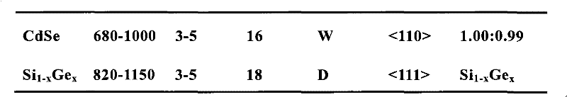
图15示出了Au和GaAs的伪二元相图,液体Au-Ga-As组分用L指代。Figure 15 shows the pseudo-binary phase diagram of Au and GaAs, the liquid Au-Ga-As component is denoted by L.
图16A-16C示出了通过LCG制备的GaAs(图16A),GaP(图16B)和GaAs0.6P0.4(图16C)纳米线的FE-SEM图像。在图16A-16C中的标尺是2μm。图16A-16C的插图分别是GaAs,GaP和GaAs0.6P0.4纳米线的TEM图像。标尺都是50nm。高衬度的特征(深色)对应于固化的纳米团簇的催化剂。16A-16C show FE-SEM images of GaAs (FIG. 16A), GaP (FIG. 16B) and GaAs 0.6 P 0.4 (FIG. 16C ) nanowires prepared by LCG. The scale bar in Figures 16A-16C is 2 μm. The insets of Figures 16A-16C are TEM images of GaAs, GaP and GaAs 0.6 P 0.4 nanowires, respectively. The scale bars are all 50 nm. High-contrast features (dark colors) correspond to solidified nanoclustered catalysts.
图17A示出了直径约20nm的GaAs纳米线的衍射衬度TEM图像。插图示出了沿<112>晶带轴记录的汇聚束电子衍射花样(ED)。ED花样的[111]方向平行于线轴,因此表明生长沿[111]方向发生。标尺等于20nm。图17B示出了直径约20nm的GaAs纳米线的高分辨TEM图像。垂直于纳米线轴的晶面距:0.32±0.01nm,与体GaAs中(111)面的晶面距0.326nm有很好的一致性。标尺等于10nm。图17C和17D分别示出了直径为10和6nm的GaAs0.6P0.4纳米线的高分辨TEM图像。在所有的三种纳米线中,(111)晶面(垂直于线轴)都清楚地被分辨。在图17C和17D中的标尺是5nm。Figure 17A shows a diffraction contrast TEM image of a GaAs nanowire with a diameter of about 20 nm. The inset shows the convergent beam electron diffraction pattern (ED) recorded along the <112> zone axis. The [111] direction of the ED pattern is parallel to the wire axis, thus suggesting that growth occurs along the [111] direction. Scale bar equals 20 nm. Figure 17B shows a high resolution TEM image of a GaAs nanowire with a diameter of about 20 nm. The interplanar distance perpendicular to the nanowire axis: 0.32±0.01nm, which is in good agreement with the interplanar distance 0.326nm of the (111) plane in bulk GaAs. Scale bar equals 10 nm. Figures 17C and 17D show high-resolution TEM images of GaAs 0.6 P 0.4 nanowires with diameters of 10 and 6 nm, respectively. In all three nanowires, the (111) crystal plane (perpendicular to the wire axis) is clearly resolved. The scale bar in Figures 17C and 17D is 5 nm.
图18A示出了通过LCG制备的CdSe纳米线的FE-SEM图像。标尺等于2μm。图18A的插图是在线端存在纳米团簇(深色特征)的单独的CdSe纳米线的TEM图像。EDX表明纳米团簇主要由Au构成。标尺是50nm。图18B示出了直径为18nm的CdSe纳米线的衍射衬度TEM图像。均一的衬度表明该纳米线是单晶体。图18B的插图是沿<001>晶带轴记录的ED花样,该图已经被标记为纤锌矿结构。ED花样的[110]方向平行于线轴,因此表明了生长沿[110]方向发生。标尺是50nm。图18C示出了直径约为13nm的CdSe纳米线的高分辨TEM图像,该图像展现出了很好地分辩(100)晶面。晶面距实验值0.36±0.01nm,与体状晶体中的间距0.372nm一致。相对于纳米线轴30°取向的(100)晶面与由ED确定的[110]生长方向一致。标尺等于5nm。Figure 18A shows the FE-SEM image of CdSe nanowires prepared by LCG. Scale bar equals 2 μm. The inset of Figure 18A is a TEM image of an individual CdSe nanowire with nanoclusters (dark features) present at the wire ends. EDX showed that the nanoclusters were mainly composed of Au. Scale bar is 50nm. Figure 18B shows a diffraction contrast TEM image of a CdSe nanowire with a diameter of 18 nm. The uniform contrast indicates that the nanowires are single crystals. The inset of Figure 18B is an ED pattern recorded along the <001> zone axis, which has been labeled as a wurtzite structure. The [110] direction of the ED pattern is parallel to the wire axis, thus indicating that growth occurs along the [110] direction. Scale bar is 50nm. Figure 18C shows a high-resolution TEM image of a CdSe nanowire with a diameter of about 13 nm, which exhibits a well-resolved (100) crystal plane. The experimental value of the crystal plane distance is 0.36±0.01nm, which is consistent with the spacing of 0.372nm in the bulk crystal. The (100) crystal plane oriented at 30° relative to the nanowire axis is consistent with the [110] growth direction determined by ED. Scale bar equals 5 nm.
单晶GaN纳米线的激光辅助催化生长Laser-Assisted Catalytic Growth of Single Crystal GaN Nanowires
已经使用激光辅助催化生长(LCG)合成了大量的单晶态GaN纳米线。(GaN,Fe)复合物靶的激光烧蚀产生了液体纳米团簇,这些团簇可以用作限制和引导晶态的纳米线的生长的催化部位。场发射扫描电子显微镜表明产品主要由线状结构组成,该线装结构具有10nm的量级的直径和大大超过1μm的长度。大量纳米线样品的粉末X射线衍射分析能被标记为GaN纤锌矿结构,显示有>95%的相纯度。单独的纳米线的透射电子显微镜,汇聚束电子衍射,和能量弥散X射线荧光分析表明它们是具有[100]生长方向的GaN单晶体。大量的单晶体的GaN的纳米线和其它技术上重要的半导体性氮化物材料的合成应该为更进一步的基础研究和应用开辟了许多机会。A large number of single-crystalline GaN nanowires have been synthesized using laser-assisted catalytic growth (LCG). Laser ablation of (GaN,Fe)composite targets produces liquid nanoclusters that can serve as catalytic sites to confine and direct the growth of crystalline nanowires. Field emission scanning electron microscopy showed that the product consisted mainly of wire-like structures with diameters of the order of 10 nm and lengths well over 1 μm. Powder X-ray diffraction analysis of bulk nanowire samples can be labeled as GaN wurtzite structure, showing >95% phase purity. Transmission electron microscopy, converged-beam electron diffraction, and energy-dispersive X-ray fluorescence analysis of individual nanowires revealed that they were GaN single crystals with a [100] growth direction. The synthesis of large quantities of single-crystal nanowires of GaN and other technologically important semiconducting nitride materials should open up many opportunities for further fundamental research and applications.
在这里,我们报到了单晶态GaN纳米线的大批量合成。GaN和催化金属的复合物靶的激光烧蚀产生了液体纳米团簇,这些团簇可以用作限制和引导晶态的纳米线生长的活性部位。场发射扫描电子显微镜(FE-SEM)表明产品主要由线状结构组成。大量纳米线样品的粉末X射线衍射(PXRD)分析能被标记为GaN纤锌矿结构,显示有>95%的相纯度。单独的纳米线的透射电子显微镜,汇聚束电子衍射,和能量弥散X射线荧光分析表明它们是具有[100]生长方向的GaN单晶体。Here, we report the large-scale synthesis of single-crystal GaN nanowires. Laser ablation of composite targets of GaN and catalytic metals produces liquid nanoclusters that can be used as active sites to confine and direct crystalline nanowire growth. Field emission scanning electron microscopy (FE-SEM) showed that the product mainly consisted of linear structures. Powder X-ray diffraction (PXRD) analysis of bulk nanowire samples can be labeled as GaN wurtzite structure, showing >95% phase purity. Transmission electron microscopy, converged-beam electron diffraction, and energy-dispersive X-ray fluorescence analysis of individual nanowires revealed that they were GaN single crystals with a [100] growth direction.
在过去的数十年中,由于纳米结构化的GaN材料用于光电子的重要的潜力,它们吸引了广泛的注意。这些研究主要集中在零维(0D)量子点和二维的量子阱结构,使用成熟的方法能很容易合成这些结构。由于与它们的合成相关联的困难,对一维(1D)GaN纳米线的研究受到限制,该研究能够使基本原理及应用研究中具有的独特机会。特别地,仅有一篇GaN纳米线生长的报道。在这个工作中,在氧化镓和NH3蒸汽存在时,使用碳纳米管作为模板来产生GaN纳米线。我们已经探究了被称之为激光辅助催化生长(LCG)的用于GaN纳米线生长的可预测的合成方法。在该方法中,脉冲激光被用来使包含预期的材料和催化剂的固体靶蒸发,由此得到的在高温度下形成的液体纳米团簇通过汽-液-固生长机理来引导生长和确定晶态纳米线的直径。该方法的一个重要的特征是,被用来确定1D生长的催化剂能够从相图数据和/或化学活性来选择。Buhro和合作者已经使用相关的被称之为溶液-液体-固体相生长的方法来在溶液中制备一些的III-V材料的纳米线,尽管不是氮化物。In the past decades, nanostructured GaN materials have attracted considerable attention due to their significant potential for optoelectronic applications. These studies mainly focus on zero-dimensional (0D) quantum dots and two-dimensional quantum well structures, which can be easily synthesized using well-established methods. Due to the difficulties associated with their synthesis, research on one-dimensional (1D) GaN nanowires has been limited, which enables unique opportunities in both fundamental and applied research. In particular, there is only one report on the growth of GaN nanowires. In this work, carbon nanotubes were used as templates to generate GaN nanowires in the presence of gallium oxide and NH3 vapor. We have explored a predictable synthetic method for the growth of GaN nanowires called laser-assisted catalytic growth (LCG). In this method, a pulsed laser is used to vaporize a solid target containing the desired material and catalyst, and the resulting liquid nanoclusters formed at high temperature guide growth and define crystallinity through a vapor-liquid-solid growth mechanism. diameter of the nanowire. An important feature of this method is that the catalysts used to determine 1D growth can be selected from phase diagram data and/or chemical activity. Buhro and collaborators have used a related method called solution-liquid-solid phase growth to prepare nanowires of some III-V materials, though not nitrides, in solution.
在GaN的情形中,没有详细的与LCG相关的三元相图(即,催化剂-Ga-N)的信息可以利用。但是,我们能够使用生长过程的知识来合理的选择催化剂。特别地,在纳米线生长条件下,催化剂应该形成与GaN混溶的液体相,但却不形成更稳定的固相。指导性原则暗示,Fe可以溶化Ga和N,但却不形成比GaN更稳定的固相化合物,Fe将是用于通过LCG的GaN纳米线生长好的催化剂。使用激光烧蚀产生催化剂纳米团簇后,纳米线生长的整个进展如图19所示。In the case of GaN, no detailed information on the ternary phase diagram (ie Catalyst-Ga-N) associated with LCG is available. However, we can use the knowledge of the growth process to rationally select the catalyst. In particular, under nanowire growth conditions, the catalyst should form a liquid phase that is miscible with GaN, but not a more stable solid phase. The guiding principles imply that Fe, which can dissolve Ga and N, but does not form a more stable solid-phase compound than GaN, would be a good catalyst for GaN nanowire growth by LCG. After generating catalyst nanoclusters using laser ablation, the overall progression of nanowire growth is shown in Figure 19.
重要地,我们发现使用GaN/Fe靶的LCG生产了高产出的纳米直径的线状结构。通过LCG生产的产品的典型的FE-SEM图像(图20A)示出了该产品主要由直径为10nm级别,长度大大超过1μm的1D结构组成;即,高纵横比的纳米线。FE-SEM数据也表明产品的组成为约90%的纳米线,其余为纳米微粒。我们也使用PXRD(图20B)评估了整个晶体结构和大量纳米线样品的相纯度。在PXRD图中所有相对尖锐的峰可以被标记为晶体常数为a=3.187和c=5.178埃的纤锌矿结构。这些值与体GaN的文献值:a=3.189和c=5.182埃符合得很好。此外,背底信号与观察到的峰的对比表明GaN纤锌矿结构相在我们的合成中所产生的晶态材料占有>95%。Importantly, we found that LCG using GaN/Fe targets produced high yields of nanometer-diameter wire-like structures. A typical FE-SEM image ( FIG. 20A ) of a product produced by LCG shows that the product is mainly composed of 1D structures with diameters on the order of 10 nm and lengths well over 1 μm; ie, high aspect ratio nanowires. FE-SEM data also indicated that the composition of the product was about 90% nanowires and the rest were nanoparticles. We also evaluated the overall crystal structure and phase purity of bulk nanowire samples using PXRD (FIG. 20B). All relatively sharp peaks in the PXRD pattern can be labeled as wurtzite structure with crystal constants a = 3.187 and c = 5.178 Angstroms. These values are in good agreement with the literature values for bulk GaN: a = 3.189 and c = 5.182 Angstroms. Furthermore, a comparison of the background signal to the observed peaks indicates that the GaN wurtzite structured phase accounts for >95% of the crystalline material produced in our synthesis.
LCG实验装置与前面所报道的装置相同。GaN/Fe复合物靶(原子比为(GaN)∶Fe=0.95∶0.05)被放置在炉中心的石英管中。该实验系统被抽真空到30毫托,接着注入无水氨气。当气压和流速分别维持在约250托和80sccm时,以30℃/min将炉温升高到900℃。接着使用脉冲Nd-YAG激光(1064nm;脉冲宽度8ns;10Hz重复;平均功率2.5W)以典型的烧蚀持续时间5min来烧蚀靶。在烧蚀后,关闭炉,使其冷却到室温。然后,排空该系统,从内部的石英管壁的端部收集到微黄色的粉末。将该产品直接用于FE-SEM和PXRD研究。将该产品悬浮在乙醇中,然后转移到TEM网格上用于TEM,CBED和EDX测量。The LCG experimental setup was the same as that reported previously. A GaN/Fe composite target (atomic ratio (GaN):Fe=0.95:0.05) was placed in a quartz tube at the center of the furnace. The experimental system was evacuated to 30 mTorr, followed by injection of anhydrous ammonia gas. While the gas pressure and flow rate were maintained at about 250 Torr and 80 sccm, respectively, the furnace temperature was raised to 900°C at 30°C/min. The target was then ablated using a pulsed Nd-YAG laser (1064 nm;
已经使用TEM,CBED和EDX进一步详细地表征了GaN纳米线的形貌、结构和成分。TEM研究表明该纳米线是直的且具有均一的直径,典型地在一端以纳米微粒结束。图20A示出了一条纳米线的有代表性的衍射衬度图像。沿着线轴的一致的衬度表明该纳米线是单晶体。在液体纳米团簇结晶化后,如所期望的那样,在纳米线端观察到的纳米微粒(深色,高的衬度特征)是多面形的(图19)。我们也使用了EDX来阐明纳米线和端部的纳米微粒的成分。在纳米线上记录的数据显示仅Ga和N的比率与GaN标样基本相同,而纳米微粒还含有Ga、N和Fe。Fe(以及Ga和N)仅在端部的纳米微粒中存在确认了在合成中Fe的催化剂的本性。The morphology, structure, and composition of GaN nanowires have been further characterized in detail using TEM, CBED, and EDX. TEM studies show that the nanowires are straight and of uniform diameter, typically ending in nanoparticles at one end. Figure 20A shows a representative diffraction contrast image of a nanowire. The consistent contrast along the wire axis indicates that the nanowire is single crystal. After crystallization of the liquid nanoclusters, the nanoparticles observed at the nanowire ends (dark, high-contrast features) were polyhedral, as expected (Fig. 19). We also used EDX to elucidate the composition of the nanowires and the nanoparticles at the tips. The data recorded on the nanowires showed that only Ga and N were present in essentially the same ratio as the GaN standard, whereas the nanoparticles also contained Ga, N and Fe. The presence of Fe (and Ga and N) only in the nanoparticles at the ends confirms the catalytic nature of Fe in the synthesis.
为了进一步钻研催化剂的重要性,我们也研究了使用Au催化剂的GaN纳米线的生长。近来金作为催化剂已被用于很多III-V和II-VI材料纳米线的生长,同样地可以期望其在GaN纳米线的生长中也有效地发挥作用。但是,Au呈现出很差的N的溶解性,于是不能有效地输运N到固/液生长界面。与该分析一致的是,我们已经不能使用Au催化剂得到GaN纳米线。我们相信这强调了催化剂的重要性以及催化剂如何能被合理地选择。To further delve into the importance of catalysts, we also investigated the growth of GaN nanowires using Au catalysts. Gold has recently been used as a catalyst for the growth of nanowires of many III-V and II-VI materials, and it can likewise be expected to function effectively in the growth of GaN nanowires. However, Au exhibits poor N solubility and thus cannot effectively transport N to the solid/liquid growth interface. Consistent with this analysis, we have been unable to obtain GaN nanowires using Au catalysts. We believe this highlights the importance of catalysts and how they can be rationally chosen.
最后,我们使用CBED和高分辨TEM(HRTEM)更详细地表征了GaN纳米线的结构。典型的纳米线的CBED花样(插图,图21A)呈现出与从衍射衬度图像推断而来的单晶结构一致的尖锐的衍射花样。对该花样的标记进一步证明了[100]方向沿线轴对准。此外,图21B示出了直径约为10nm的GaN纳米线的HRTEM晶格像。该图像沿<001>晶带轴记录,清楚地示出了纳米线的单晶结构和沿[100],[010]和[-110]方向的晶面。该图像证明了[100]方向与线轴平行,因此证实了在GaN纳米线中的[100]生长方向。Finally, we characterize the structure of GaN nanowires in more detail using CBED and high-resolution TEM (HRTEM). The CBED pattern of a typical nanowire (inset, Figure 21A) exhibits a sharp diffraction pattern consistent with the single crystal structure inferred from the diffraction contrast image. The labeling of this pattern further demonstrates that the [100] direction is aligned along the wire axis. In addition, FIG. 21B shows an HRTEM lattice image of a GaN nanowire with a diameter of about 10 nm. The image was recorded along the <001> zone axis, clearly showing the single-crystal structure of the nanowires and crystal planes along the [100], [010] and [−110] directions. This image demonstrates that the [100] direction is parallel to the wire axis, thus confirming the [100] growth direction in GaN nanowires.
总之,我们探究了用于合理地合成GaN纳米线的LCG方法。获得了具有唯一的[100]生长方向的单晶体的高纯度GaN纳米线。我们相信,这种基于催化剂和生长条件的可预测的选择的方法能很容易地拓展到InN,(GaIn)N合金和相关的氮化物纳米线的合成。,大量GaN单晶纳米线和其他技术上重要的半导体氮化物材料的合成被期望能为未来的基础研究和应用开辟很多机会。In summary, we explored an LCG approach for the rational synthesis of GaN nanowires. Single-crystal, high-purity GaN nanowires with a unique [100] growth direction were obtained. We believe that this approach based on the predictable choice of catalyst and growth conditions can be easily extended to the synthesis of InN, (GaIn)N alloys and related nitride nanowires. , the synthesis of large quantities of GaN single-crystal nanowires and other technologically important semiconducting nitride materials is expected to open up many opportunities for future fundamental research and applications.
图19示出了使用激光辅助催化生长GaN纳米线的示意图。Figure 19 shows a schematic diagram of the growth of GaN nanowires using laser assisted catalysis.
图20A示出了使用LCG合成的大量的GaN纳米线的FE-SEM(LEO 982)图像。标尺等于1μm。图20B示出了在大量的GaN纳米线上记录的PXRD(Scintag,XDS2000)花样。在峰上的数字对应于闪锌矿结构的(hkl)值。Figure 20A shows a FE-SEM (LEO 982) image of a large number of GaN nanowires synthesized using LCG. Scale bar equals 1 μm. Figure 20B shows a PXRD (Scintag, XDS2000) pattern recorded on a large number of GaN nanowires. The numbers on the peaks correspond to the (hkl) values for the sphalerite structure.
图21A示出了GaN纳米线的衍射衬度TEM(Philips,EM420)图像,该纳米线以更高(深色)衬度的多面形的纳米微粒结束。在图21A中的插图示出了用白环标记出的区域上沿<001>晶带轴记录的CBED花样。白色标尺等于50nm。图21B示出了另一个直径约为10nm的纳米线的HRTEM(JEOL 2010)图像。该图像沿<001>晶带轴得到。[100],[010]和[-110]方向用平行于线轴的[100]表示。白色标尺等于5nm。Figure 21A shows a diffraction contrast TEM (Philips, EM420) image of a GaN nanowire ending in higher (dark) contrast polyhedral nanoparticles. The inset in Figure 21A shows the CBED pattern recorded along the <001> zone axis on the area marked with a white circle. White scale bar equals 50nm. Figure 21B shows another HRTEM (JEOL 2010) image of a nanowire with a diameter of about 10 nm. The image was taken along the <001> zone axis. [100], [010] and [-110] directions are indicated by [100] parallel to the axis of the line. White scale bars equal to 5nm.
由磷化铟纳米线结构单元组装的纳米尺度的电子和光电子器件Nanoscale electronic and optoelectronic devices assembled from indium phosphide nanowire building blocks
如纳米线(NWs)和纳米管(NTs)的一维纳米结构理想地适合于电荷载流子和激子的有效的输运,因此被认为是用于纳米尺度的电子学和光电子学的关键的结构单元。对在碳纳米管中的电子输运的研究已经导致了场效应管、单电子管、整流结和化学传感器的产生,这些结果显示了从这些材料可能的令人激动的应用,尽管由于半导体性或金属性的纳米管的选择性生长和/或组装现在还不可能,纳米管结构单元的使用受到相当的限制。将纳米尺度结构用作用于有源器件和器件阵列的倒置组装的结构单元将需要不同单元的电性质是确定和可控制的,该应用将消除对于昂贵的组装线的需求。最后,我们报道了来自化合物半导体纳米线结构单元的功能性纳米尺度器件的合理的组装,在这些纳米线结构单元中电性质通过掺杂得到控制。栅依赖输运测量证明,磷化铟(InP)纳米线能通过可控的n型和p型掺杂来合成,并能如纳米尺度的场效应晶体管那样运作。此外,通过形成交叉的纳米线阵列,清晰的(well-defined)n-和p-型材料的可用性使p-n结的产生成为可能。输运测量揭示纳米尺度的p-n结展示了清晰的电流整流性。重要的是,正向偏压的InP p-n结展示了强的,量子限制的光发射,使得这些结构也许是迄今所创造的最小的发光二极管。最后,电场引导的组装被视为能从这些新的纳米尺度的结构单元创造出高度集成的和功能性的器件的一种策略。One-dimensional nanostructures such as nanowires (NWs) and nanotubes (NTs) are ideally suited for the efficient transport of charge carriers and excitons and are thus considered key for nanoscale electronics and optoelectronics structural unit. Research on electron transport in carbon nanotubes has led to field-effect transistors, single-electron tubes, rectifying junctions, and chemical sensors. These results show the exciting applications possible from these materials, although due to semiconducting or Selective growth and/or assembly of metallic nanotubes is not currently possible, and the use of nanotube building blocks is rather limited. The use of nanoscale structures as building blocks for inverted assembly of active devices and device arrays would require that the electrical properties of the different cells be determined and controllable, and this application would eliminate the need for expensive assembly lines. Finally, we report the rational assembly of functional nanoscale devices derived from compound semiconductor nanowire building blocks in which electrical properties are controlled by doping. Gate-dependent transport measurements demonstrate that indium phosphide (InP) nanowires can be synthesized with controllable n-type and p-type doping and behave like nanoscale field-effect transistors. Furthermore, the availability of well-defined n- and p-type materials enables the creation of p-n junctions by forming intersecting nanowire arrays. Transport measurements reveal nanoscale p-n junctions exhibiting clear current rectification. Importantly, forward-biased InP p-n junctions exhibit strong, quantum-confined light emission, making these structures perhaps the smallest light-emitting diodes ever created. Finally, electric field-guided assembly is considered as a strategy to create highly integrated and functional devices from these new nanoscale building blocks.
已经通过如前所述的激光辅助催化生长(LCG)制备了单晶体的InP纳米线。分别使用碲(Te)和锌(Zn)作为掺杂剂制备了n型和p型的InP纳米线,并发现这些纳米线与没有添加掺杂剂的纳米线有相似的高质量。已合成的Zn掺杂的InP纳米线的场发射扫描电子显微镜(FE-SEM)图像(图22A)证明这些线长度延长到数十个纳米,直径在10纳米的量级。高分辨透射电子显微镜(TEM)图像(插图,图22A)进一步示出了该掺杂的纳米线是生长方向为<111>的单晶体。通常的,在TEM图像中是可以看见纳米线上的1-2纳米的不定形包覆层。该薄层归结于纳米线在合成后暴露在空气中时形成的氧化物。通过能量弥散X射线衍射(EDX)分析所确定的单独的纳米线的全部的成分被发现是1∶1In∶P,因此确认了纳米线的化学计量的成分。但是,EDX和其他元素分析方法还不够灵敏来确定单独的纳米线中的掺杂水平。Single crystal InP nanowires have been prepared by laser assisted catalytic growth (LCG) as described previously. n-type and p-type InP nanowires were prepared using tellurium (Te) and zinc (Zn) as dopants, respectively, and it was found that these nanowires had similar high quality to those without dopant addition. Field emission scanning electron microscopy (FE-SEM) images of as-synthesized Zn-doped InP nanowires (FIG. 22A) demonstrate that these wires extend to tens of nanometers in length and on the order of 10 nanometers in diameter. High-resolution transmission electron microscopy (TEM) images (inset, FIG. 22A ) further show that the doped nanowires are single crystals with a growth direction of <111>. Typically, 1-2 nm amorphous coatings on the nanowires can be seen in TEM images. The thin layer is down to oxides that form when the nanowires are exposed to air after synthesis. The overall composition of individual nanowires determined by energy dispersive X-ray diffraction (EDX) analysis was found to be 1:1 In:P, thus confirming the stoichiometric composition of the nanowires. However, EDX and other elemental analysis methods are not sensitive enough to determine doping levels in individual nanowires.
为了确认在纳米线中掺杂剂的存在和类型,我们已经在单独的纳米线上进行了栅-依赖,两端法输运测量。在这些测量中,对于n-和p-型的纳米线,纳米线的电导将以相反的方向响应于栅电压(Vg)的变化。特别的,对于n型的纳米线,Vg>0将导致电子的积累和电导的增加;而对于p型的纳米线,相同施加电压的栅将消耗空穴和降低电导。图22B和22C和100c分别示出了从单独的Te-和Zn-掺杂的纳米线获得的典型的栅依赖I-V曲线。对于两类型的纳米线,在Vg=0时,I-V曲线都是近似线性的,表明金属电极与纳米线是欧姆接触。在Te掺杂的纳米线上记录的输运数据(图22B)表明对于Vg>0电导增加,而对于Vg<0电导下降。这些数据清楚地表明Te掺杂的InP纳米线是n型的。与n型,Te掺杂的InP纳米线相比,在Zn掺杂的纳米线上记录的栅依赖输运数据示出了随Vg的变化反向的电导变化。特别地,对于Vg>0电导下降,对于Vg<0电导增加(图22C)。这些结果表明Zn掺杂的InP纳米线是p型的。To confirm the presence and type of dopants in the nanowires, we have performed gate-dependent, two-terminal transport measurements on individual nanowires. In these measurements, the conductance of the nanowires will respond to changes in gate voltage (Vg) in opposite directions for n- and p-type nanowires. In particular, for n-type nanowires, Vg > 0 will lead to accumulation of electrons and increase in conductance; while for p-type nanowires, the same applied gate voltage will consume holes and reduce conductance. Figures 22B and 22C and 100c show typical gate-dependent I-V curves obtained from individual Te- and Zn-doped nanowires, respectively. For the two types of nanowires, when Vg=0, the I-V curves are approximately linear, indicating that the metal electrode and the nanowires are in ohmic contact. Transport data recorded on Te-doped nanowires (FIG. 22B) showed an increase in conductance for Vg>0 and a decrease in conductance for Vg<0. These data clearly indicate that the Te-doped InP nanowires are n-type. Gate-dependent transport data recorded on Zn-doped nanowires show an inverse change in conductance with Vg changes compared to n-type, Te-doped InP nanowires. In particular, conductance decreased for Vg > 0 and increased for Vg < 0 (FIG. 22C). These results indicate that the Zn-doped InP nanowires are p-type.
我们的结果具有相当的可重复性。在超过二十根直径从20nm到100nm的单独的纳米线上进行的测量在每种情形下显示出栅效应,该效应与在InP纳米线合成中使用掺杂剂是一致的。此外,栅电压可以被用来完全地耗尽n-型和p-型的纳米线中的电子和空穴,以至电导变得不可测量的小。例如,当Vg小于或等于-20V时,在图22B中的纳米线的电导可以从导通(开)状态转换到截止(关)状态,于是该纳米线可以如场效应管那样工作。对于一些纳米线,电导调制能够如4-5个数量级大。相对高的切换电压是与在我们的测量中所使用的厚(600nm)氧化物阻挡层有关。该栅依赖行为与金属-氧化物-半导体(MOS)场效应管和近来的半导体纳米管场效应管的研究相似。我们关于纳米管工作的一个重要的特色就是,在每一条纳米线中,能够获得可预测的半导体行为。综合起来,这些结果清楚地说明了单晶体InP纳米线能够被合成而具有可控的载流子类型。因为这些纳米线以大批量的形式被生产,它们代表了一种可以容易得到的用于组装器件和器件阵列的材料。Our results are fairly reproducible. Measurements performed on more than twenty individual nanowires ranging in diameter from 20 nm to 100 nm showed in each case a gate effect consistent with the use of dopants in the synthesis of InP nanowires. Furthermore, the gate voltage can be used to completely deplete both n-type and p-type nanowires of electrons and holes, so that the conductance becomes immeasurably small. For example, when Vg is less than or equal to -20V, the conductance of the nanowire in FIG. 22B can be switched from the conduction (on) state to the off (off) state, so the nanowire can work like a field effect transistor. For some nanowires, the conductance modulation can be as large as 4-5 orders of magnitude. The relatively high switching voltage is related to the thick (600 nm) oxide barrier layer used in our measurements. This gate-dependent behavior is similar to that of metal-oxide-semiconductor (MOS) FETs and more recently semiconducting nanotube FETs. An important feature of our work on nanotubes is the ability to obtain predictable semiconducting behavior within each nanowire. Taken together, these results clearly demonstrate that single-crystal InP nanowires can be synthesized with controllable carrier types. Because these nanowires are produced in large quantities, they represent a readily available material for assembling devices and device arrays.
通过在两条或更多线之间形成结,清晰的n-型和p-型纳米线结构单元的可用性开辟了创建复杂功能的器件的可能。为了探索这个让人兴奋的机会,我们已经分别研究了通过使用交叉两个n型,两个p型,及一个n型和一个p型纳米线形成的n-n,p-p和p-n结的输运性质。图23A示出了使用直径为29nm和40nm的纳米线形成的有代表性的交叉纳米线器件。为了以下讨论的简便,将四个臂用A,B,C,D指代。重要的是,对于每一个实验,被研究的结的类型是可以控制的因为我们能够在组装之前选择用于制造交叉的结的纳米线的类型。The availability of well-defined n-type and p-type nanowire building blocks opens up the possibility of creating complex functional devices by forming junctions between two or more wires. To explore this exciting opportunity, we have investigated the transport properties of n-n, p-p, and p-n junctions formed by intersecting two n-type, two p-type, and one n-type and one p-type nanowires, respectively. Figure 23A shows representative interdigitated nanowire devices formed using nanowires with diameters of 29 nm and 40 nm. For simplicity in the following discussion, the four arms will be referred to as A, B, C, D. Importantly, for each experiment, the type of junction studied was controllable because we were able to select the type of nanowire used to make the crossed junction prior to assembly.
图23B和23C分别示出了在n-n和p-p结上记录的电流-电压(I-V)数据。对于两种类型的结,在单独的纳米线上记录的输运数据(AC,BD)都显示出线性或近乎线性的I-V行为(曲线80,图23B和曲线82,图23C)。这些结果表明实验中所使用的金属电极与纳米线是欧姆或近似欧姆性的接触,将不会对穿过结的I-V测量造成非线性的影响。通常,穿过n-n和p-p结进行的I-V输运测量显示出线性或近似线性的行为,而许可我们推断出关于用这种方法制备的结的两个重要的观点。第一,在单独的纳米线之间的界面氧化物不会产生明显的隧道势垒,因为这样的势垒将会导致高的非线性I-V行为。第二,流过每一对相邻的臂记录的I-V曲线显示出相似的电流水平,这些值小于单独的纳米线自身的值。这些结果表明结支配输运行为。最后,我们的数据表明,尽管接触面积小(10-12-10-10cm2)和制作结的方法简单,单独的纳米线在相互之间有好的合理的电接触。Figures 23B and 23C show current-voltage (IV) data recorded across nn and pp junctions, respectively. Transport data (AC, BD) recorded on individual nanowires showed linear or nearly linear IV behavior for both types of junctions (
在单独的纳米线之间好的接触为研究这些纳米线来制造功能性器件提供了基础。作为例子,我们已经从交叉的p-和n-型纳米线制作了p-n结。通过具有中间干燥的n-和p-型纳米线稀溶液的依次沉积,这些结能够被可重复地制造。图23D示出了交叉的纳米线p-n结的典型的I-V行为。单独的n-和p-型纳米线元件的线性的I-V(曲线84和86)表明纳米线和金属电极之间是欧姆接触。穿过p-n结的输运性质(曲线88)示出了清楚的电流整流;即,反向偏压时没有电流流动,而正向偏压时有急剧的电流上升。重要的是,该行为与体半导体p-n结相似,这形成了许多关键的电子和光电子器件的基础。在标准的p-n结中,整流来自于在p-和n-型材料之间的界面上形成的势垒。当结是正向偏压时(p-一侧是正偏压),势垒减小,相对大的电流能够流过结;另一方面,在反向偏压时,仅有少量的电流能够流过结,因为势垒被进一步增强了。Good contacts between individual nanowires provide the basis for studying these nanowires to fabricate functional devices. As an example, we have fabricated p-n junctions from intersecting p- and n-type nanowires. These junctions can be reproducibly fabricated by sequential deposition of dilute solutions of n- and p-type nanowires with intermediate drying. Figure 23D shows typical I-V behavior of intersecting nanowire p-n junctions. The linear I-V of individual n- and p-type nanowire elements (curves 84 and 86) indicate an ohmic contact between the nanowire and the metal electrode. The transport properties (curve 88) across the p-n junction show clear current rectification; ie, no current flow when reverse biased, but a sharp current rise when forward biased. Importantly, the behavior is similar to that of bulk semiconductor p-n junctions, which form the basis of many key electronic and optoelectronic devices. In a standard p-n junction, rectification comes from the formation of a potential barrier at the interface between the p- and n-type materials. When the junction is forward biased (the p- side is forward biased), the potential barrier is reduced and a relatively large current can flow through the junction; on the other hand, only a small amount of current can flow when it is reverse biased junction, because the barrier is further enhanced.
有几个原因使我们相信所观察到的整流是因为在p-型和n-型InP纳米线之间的交叉点形成的p-n结。第一,用来制造结的单独的p-和n-型纳米线的线性或近似线性的行为表明在纳米线和金属电极之间形成了欧姆接触。这就排除了整流来自金属-半导体肖特基(Schottky)二极管的可能性。第二,通过每对相邻的电极(AB,AD,CB,CD)所确定结的I-V行为(图23D中曲线88)展示了相似的整流效应和电流水平,这也比通过单独的纳米线的电流水平小得多。这些结果证明结支配了I-V行为。第三,四端测量显示出相似的I-V和整流,仅与在同样电流水平下的二端测量相比有略微小的压降(0.1-0.2V),该四端测量中,在测量穿过两个独立的电极(如,C-D)的结的压降时,电流通过两个相邻的电极(A-B)。最后,在10个独立的p-n结上进行的测量在I-V数据中显示了相似的整流;即,当p型纳米线是正偏压时,明显的电流仅能流过p-n结。Several reasons lead us to believe that the observed rectification is due to the p-n junction formed at the intersection between the p-type and n-type InP nanowires. First, the linear or near-linear behavior of the individual p- and n-type nanowires used to make the junctions indicates the formation of ohmic contacts between the nanowires and the metal electrodes. This rules out the possibility that the rectification comes from a metal-semiconductor Schottky diode. Second, the I-V behavior of the junction determined by each pair of adjacent electrodes (AB, AD, CB, CD) (
上面的数据明确地表明我们现在能合理地制作纳米尺度的p-n结。在像InP的直接能隙半导体中,p-n结形成了用于包括发光二极管(LED)和激光器的关键的光电子器件的基础。为了评估我们的纳米尺度的器件是否有相似的行为,我们从交叉的纳米线p-n结研究了光致发光(PL)和电致发光(EL)。重要的是,EL可以从正向偏压的这些纳米尺度的结中轻易地观察到。图24A示出了从在正向偏压的典型的纳米线p-n结得到的EL图像,插图示出了从交叉的纳米线结得到的PL图像。PL图像清楚地显示两个拉长的线状的结构,EL图像示出了来自于点状源的光。对比EL和PL图像表明EL最大值的位置对应于PL图像中的交叉点,于是证明了光确实从纳米线的p-n结中发出。The above data clearly show that we can now reasonably fabricate nanoscale p-n junctions. In direct gap semiconductors like InP, p-n junctions form the basis for key optoelectronic devices including light emitting diodes (LEDs) and lasers. To assess whether our nanoscale devices behave similarly, we investigated photoluminescence (PL) and electroluminescence (EL) from intersecting nanowire p-n junctions. Importantly, EL can be readily observed from these nanoscale junctions in forward bias. Figure 24A shows the EL image obtained from a typical nanowire p-n junction at forward bias, and the inset shows the PL image obtained from a crossed nanowire junction. The PL image clearly shows two elongated linear structures and the EL image shows light from a point source. Comparing the EL and PL images shows that the position of the EL maximum corresponds to the intersection point in the PL image, thus proving that light is indeed emitted from the p-n junction of the nanowire.
结的I-V特征(插图,图24B)示出了在~1.5V具有急剧的电流上升的清楚的整流。结的EL强度相对于电压的曲线表明,在如1.7V低的电压下用我们的系统能够检测到有效的光。EL强度随着偏压迅速升高,类似于I-V行为。EL光谱(图24C)示出了在820nm附近的最大的强度,该值相对于InP体材料的带隙(925nm)有明显的蓝移。该蓝移部分地是因为激子的量子限制,尽管其他因素也可能有影响。在从由小较小的(和较大的)直径的纳米线(图24D)组装的p-n结记录的EL结果中可以清楚地看见量子限制的重要性,其结果显示了较大(较小)的蓝移。在这些纳米LEDs中通过尺寸调节颜色的能力在未来也许是特别有用的。这些最初的器件的量子效应(电子到光子)相对地低(~0.001%),这并不让人吃惊,因为我们对优化几乎没有加以注意。该效率与早期的体InP的LEDs的效率(~0.002%)是相当的。我们将低的量子效率归结为经由表面状态的非辐射复合,并且相信该有害的过程能够通过表面钝化加以减少。The I-V characteristics of the junction (inset, Figure 24B) show clear rectification at -1.5V with a sharp current rise. The plot of the junction's EL intensity versus voltage shows that effective light can be detected with our system at voltages as low as 1.7V. The EL intensity rises rapidly with bias, similar to the I-V behavior. The EL spectrum (FIG. 24C) shows a maximum intensity around 820 nm, a value that is clearly blue-shifted relative to the band gap (925 nm) of the InP bulk material. This blue shift is due in part to the quantum confinement of excitons, although other factors may also play a role. The importance of quantum confinement can be clearly seen in the EL results recorded from p-n junctions assembled from smaller (and larger) diameter nanowires (Fig. blue shift. The ability to tune color by size in these nano-LEDs may be particularly useful in the future. The quantum effects (electrons to photons) of these initial devices were relatively low (~0.001%), which is not surprising since we paid little attention to optimization. This efficiency is comparable to that of early bulk InP LEDs (-0.002%). We attribute the low quantum efficiency to nonradiative recombination via surface states, and believe that this deleterious process can be reduced by surface passivation.
GaN是一种直接宽带隙半导体材料,它可以在室温发射短波区域(UV和蓝光)的光。在需要高强度、高能效和可靠光源的地方,蓝光LEDs是重要的发射器。它对于使生产全色调LED显示器和LED白光灯成为可能很重要,因为蓝色是三种基本色(红,绿,蓝)之一。GaN is a direct wide-bandgap semiconductor material that emits light in the short-wavelength region (UV and blue light) at room temperature. Blue LEDs are important emitters where high-intensity, energy-efficient and reliable light sources are required. It is important to enable the production of full-color LED displays and LED white lights, since blue is one of the three basic colors (red, green, blue).
这里,我们报到了第一个制作的BLUE/UV纳米LEDs(光发射区域在10nm量级),它是使用p型的Si和n型(非故意掺杂)的GaN纳米线构造而成。与我们所报到的在近IR区域发光的纳米LEDs一起,我们显示了使用可以覆盖全部色谱的不同的材料来制作LEDs的巨大潜力。Here, we report the first fabricated BLUE/UV nano-LEDs (light emission region on the order of 10 nm) constructed using p-type Si and n-type (unintentionally doped) GaN nanowires. Together with our reported nano-LEDs emitting in the near-IR region, we show the great potential to fabricate LEDs using different materials that can cover the entire color spectrum.
图25A示出了两个p型Si和n型GaN交叉的纳米结得到的EL图像。该p-Si用硼掺杂。图25B示出了多个栅电压下的电压相对于电流的关系。纳米结在不同的栅电压都显示出了好的整流性。如图25C所示的EL光谱显示了在380nm和470nm左右的光发射。n-InP和p-Si纳米结具有好的整流性。Figure 25A shows an EL image obtained from a nanojunction intersected by two p-type Si and n-type GaN. The p-Si is doped with boron. Figure 25B shows voltage versus current at various gate voltages. The nanojunction shows good rectification at different gate voltages. The EL spectrum shown in Figure 25C shows light emission around 380nm and 470nm. n-InP and p-Si nanojunctions have good rectification.
为了制作高集成的基于纳米线的器件将最终需要将这些结构单元排列和组装为清晰的阵列的技术。为了证明这下一个发展阶段的可行性,我们使用电场(E-场)来将单独的纳米线排列和定位为平行和交叉的阵列——用于集成化的两种基本的几何图形。通过将纳米线的溶液置于电极之间(图26A),然后施加50-100V的偏压,实现E-场引导的组装。在平行电极之间的氯苯悬浮的纳米线的排列的情形中,可以轻易地看到该方法的潜力。FE-SEM图像表明,几乎所有的纳米线都垂直于平行电极、顺着E-场的方向进行排列。我们也使用了电极阵列来定位在特殊位置的单独的纳米线。例如,在一列电极之间的纳米线的E-场的组装(图26C)演示了能放置单独的纳米线来搭接直径上对置的电极对,形成平行的阵列。此外,通过改变场的方向,该对准能够以逐层的方式进行以生产交叉的纳米线结(图26D)。这些数据清楚地表明E场组装代表了一种通过高度地方向和空间控制来合理地沉积单独的纳米线的策略。我们相信,使用我们的纳米线结构单元以及E场和/或其他组装技术,高集成的功能器件将是可以得到的。Techniques for arranging and assembling these building blocks into well-defined arrays will eventually be required in order to fabricate highly integrated nanowire-based devices. To demonstrate the feasibility of this next stage of development, we used electric fields (E-fields) to align and position individual nanowires into parallel and crossed arrays—two basic geometries for integration. E-field guided assembly was achieved by placing a solution of nanowires between electrodes (Fig. 26A) and then applying a bias voltage of 50-100V. The potential of this approach can be easily seen in the case of an arrangement of chlorobenzene-suspended nanowires between parallel electrodes. FE-SEM images show that almost all nanowires are aligned perpendicular to the parallel electrodes and along the direction of the E-field. We also used electrode arrays to position individual nanowires at specific locations. For example, E-field assembly of nanowires between a column of electrodes (FIG. 26C) demonstrates that individual nanowires can be placed to bridge diametrically opposed pairs of electrodes, forming parallel arrays. Furthermore, by changing the direction of the field, this alignment can be performed in a layer-by-layer manner to produce intersecting nanowire junctions (Fig. 26D). These data clearly demonstrate that E-field assembly represents a strategy to rationally deposit individual nanowires with a high degree of orientation and spatial control. We believe that highly integrated functional devices will be achievable using our nanowire building blocks together with E-field and/or other assembly techniques.
整体来看,本文中介绍的结果提供了一种用于纳米尺度的电子和光电子器件的倒置组装的合理方法。在没有数十亿美元的装配线的条件下,我们已被证明的组装有源(active)器件的能力对于该领域是及其重要的,我们相信对于眼前和长期的发展奠定了基础。我们相信,现在可以利用的大范围的纳米材料和清楚界定的用来控制它们电性质的能力,将使覆盖整个可见光和近红外区域的纳米尺度的LEDs(例如,用于蓝光的GaN纳米线)成为可能。这样的纳米尺度的光源也许在创造新类型的高度平行的光传感器和用于纳米电子学中的光学互联器的过程中是有用的。而且,掺杂的纳米线结构单元的组装明显地具有创造许多其他类型的电子器件,甚至可能创造激光器的潜力。Taken together, the results presented in this paper provide a rational approach for the inverted assembly of nanoscale electronic and optoelectronic devices. Our proven ability to assemble active devices without a multi-billion dollar assembly line is extremely important to the field and we believe lays the groundwork for immediate and long-term growth. We believe that the large range of nanomaterials now available and the well-defined ability to control their electrical properties will enable nanoscale LEDs covering the entire visible and near-infrared region (e.g., GaN nanowires for blue light) become possible. Such nanoscale light sources may be useful in creating new types of highly parallel photosensors and optical interconnects for use in nanoelectronics. Moreover, the assembly of doped nanowire building blocks clearly has the potential to create many other types of electronic devices, and possibly even lasers.
使用LCG合成了InP纳米线。该LCG靶典型地由94%(原子比率)的InP,作为催化剂的5%的Au,和作为掺杂元素的1%的Te或Zn组成。在生长过程中,炉温(中部)被设置在800℃,靶被放置在炉的上游端而不是中间。使用脉冲(8ns,10Hz)Nd-YAG激光(1064nm)来蒸发靶。典型地,生长进行10分钟,在炉的下游、冷端收集纳米线。InP nanowires were synthesized using LCG. The LCG target typically consists of 94% (atomic ratio) of InP, 5% of Au as a catalyst, and 1% of Te or Zn as a doping element. During growth, the furnace temperature (middle) was set at 800°C and the target was placed at the upstream end of the furnace instead of the middle. The target was evaporated using a pulsed (8 ns, 10 Hz) Nd-YAG laser (1064 nm). Typically, growth is performed for 10 minutes with the nanowires collected at the downstream, cold end of the furnace.
使用已公开的程序在单独的纳米线上进行输运测量。简单地说,首先将纳米线分散在乙醇中,然后沉积在氧化后的硅衬底(600nm氧化物,1-10Ω.cm电阻率)上,导电硅用作背栅。使用电子束光刻技术(JEOL6400)来制作纳米线的电接触。热蒸镀Ni/In/Au接触电极。使用计算机控制下的噪声<1pA的自制系统进行电子输运测量。Transport measurements were performed on individual nanowires using published procedures. Briefly, the nanowires were first dispersed in ethanol, and then deposited on an oxidized silicon substrate (600nm oxide, 1-10Ω.cm resistivity), and the conductive silicon was used as the back gate. Electron beam lithography (JEOL6400) was used to make the electrical contacts of the nanowires. Thermally evaporated Ni/In/Au contact electrodes. Electron transport measurements were performed using an in-house system with <1 pA noise under computer control.
通过随机沉积获得n-n和p-p结。我们首先使用相对高的浓度将纳米线沉积到氧化后的硅衬底上,确定交叉的纳米线的位置,接着通过电子束光刻技术在交叉的所有的四个臂上制作电极。Ni/In/Au电极被用来与纳米线进行接触。Obtain n-n and p-p junctions by random deposition. We first deposited the nanowires onto an oxidized silicon substrate using relatively high concentrations, positioned the crossing nanowires, and then fabricated electrodes on all four arms of the crossing by electron beam lithography. Ni/In/Au electrodes were used to make contact with the nanowires.
通过逐层地沉积获得p-n结。首先,沉积一种类型的纳米线(例如,n型)的稀溶液到衬底上,记录单独的纳米线的位置。在第二步中,沉积另一种类型的纳米线(例如,p型)的稀溶液,记录交叉的n-和p型纳米线的位置。接着制作金属电极和进行输运测量。The p-n junction is obtained by layer-by-layer deposition. First, a dilute solution of one type of nanowire (eg, n-type) is deposited onto a substrate, and the positions of individual nanowires are recorded. In a second step, a dilute solution of another type of nanowire (eg, p-type) is deposited, and the position of the intersecting n- and p-type nanowires is recorded. Metal electrodes are then fabricated and transport measurements are performed.
使用自制的微光仪器研究EL。使用PL或散射光(540nm,Ar离子激光器)来定位结的位置。在对结进行定位时,关闭激发激光,接着正向偏压结。使用液氮冷却的CCD相机来拍摄EL图像,通过在300mm的分光计中使用150线/mm的栅来分散EL得到EL光谱。EL was studied using a homemade low-light instrument. PL or scattered light (540 nm, Ar-ion laser) was used to localize the junction position. To position the junction, the excitation laser is turned off, then the junction is forward biased. EL images were taken using a liquid nitrogen cooled CCD camera, and the EL spectrum was obtained by dispersing the EL using a 150 line/mm grid in a 300 mm spectrometer.
图22A-22C说明了InP纳米线的掺杂和电子输运。图22A示出了Zn掺杂的InP纳米线的典型的FE-SEM图像。标尺是10μm。插图是一条直径为26nm的纳米线的TEM晶格像。可以看见(111)晶面垂直于线轴。标尺是10nm。图22B和22C分别示出了Te和Zn掺杂的纳米线的栅依赖的I-V行为。图22B和22C中的插图示出了使用两端Ni/In/Au接触电极测量的纳米线。标尺等于1μm。在图22B中的纳米线的直径为47nm,在图22C中的纳米线的直径为45nm。在对应的I-V曲线上、图的右手边,标出了在测量中使用的具体的栅电压。数据在室温下测量。22A-22C illustrate the doping and electron transport of InP nanowires. Figure 22A shows a typical FE-SEM image of Zn-doped InP nanowires. Scale bar is 10 μm. The inset is a TEM lattice image of a nanowire with a diameter of 26 nm. It can be seen that the (111) crystal plane is perpendicular to the line axis. Scale bar is 10 nm. Figures 22B and 22C show the gate-dependent I-V behavior of Te and Zn doped nanowires, respectively. The insets in Figures 22B and 22C show nanowires measured using two-ended Ni/In/Au contact electrodes. Scale bar equals 1 μm. The nanowires in FIG. 22B have a diameter of 47 nm, and the nanowires in FIG. 22C have a diameter of 45 nm. On the corresponding I-V curve, on the right-hand side of the figure, the specific gate voltage used in the measurement is marked. Data are measured at room temperature.
图23A-23D说明了交叉的纳米线的结和电性质。图23A示出了具有Ni/In/Au接触电极的典型的交叉纳米线器件的FE-SEM图像。标尺等于2μm。纳米线的直径是29nm(A-C)和40nm(B-D);被用来制作器件的纳米线的直径在20-75nm的范围内。图23B-23D分别示出了n-n,p-p和p-n结的I-V行为。曲线80和82分别对应于结中单独的n-和p-纳米线的I-V行为。曲线88表示穿过结的I-V行为。为了更好地查看,在图23D中记录的p-和n-纳米线的电流被除以10。实线代表穿过一对相邻的臂上的输运行为,点化线代表另外三对相邻臂的输运行为。数据在室温下测量。23A-23D illustrate junction and electrical properties of intersecting nanowires. Figure 23A shows a FE-SEM image of a typical intersecting nanowire device with Ni/In/Au contact electrodes. Scale bar equals 2 μm. The diameters of the nanowires are 29 nm (A-C) and 40 nm (B-D); the diameters of the nanowires used to make the devices are in the range of 20-75 nm. Figures 23B-23D show the I-V behavior of n-n, p-p and p-n junctions, respectively.
图24A-24D说明了纳米线p-n结的光电特征。图24A是从在2.5V正向偏压的纳米线p-n结中发射的光的EL图像。在图24A中的插图示出了结的PL图像。它们的标尺都等于5μm。图24B示出了EL强度相对于电压的关系。在图24B中的插图示出了I-V特征,插图中的插图示出了结自身的FE-SEM图像。标尺等于5μm。形成该结的n型和p型纳米线分别具有65和68nm的直径。图24C示出了在图24A中的结的EL光谱。该光谱的峰值在820nm。图24D示出了从第二正向偏压的交叉的纳米线p-n结记录的EL光谱。该EL的最大值出现680nm。在图24D中的插图示出了该EL图像,并证明了该EL产生自结区域。标尺是5μm。形成该结的n型和p型纳米线分别具有39和49nm的直径。24A-24D illustrate the optoelectronic characteristics of nanowire p-n junctions. Figure 24A is an EL image of light emitted from a nanowire p-n junction forward biased at 2.5V. The inset in Figure 24A shows the PL image of the junction. Their scale bars are all equal to 5 μm. Figure 24B shows EL intensity versus voltage. The inset in Figure 24B shows the I-V characteristics, and the inset in the inset shows the FE-SEM image of the junction itself. Scale bar equals 5 μm. The n-type and p-type nanowires forming the junction have diameters of 65 and 68 nm, respectively. Fig. 24C shows the EL spectrum of the junction in Fig. 24A. The peak of this spectrum is at 820nm. Figure 24D shows the EL spectrum recorded from a second forward biased crossed nanowire p-n junction. The maximum value of this EL appears at 680 nm. The inset in Figure 24D shows the EL image and demonstrates that the EL arises from the junction region. Scale bar is 5 μm. The n-type and p-type nanowires forming the junction have diameters of 39 and 49 nm, respectively.
图26A-26D说明了使用E场的平行和正交的组装。图26A是E场排列的示意图。在衬底上(蓝色)沉积-滴纳米线溶液后,将电极(橙色)置于50-100V的偏压。图26B示出了在两个平行电极间排列的纳米线的平行阵列。纳米线被悬浮在氯苯中,使用所施加的100V的偏压进行排列。图26C示出了使用80V偏压的E场组装后获得的空间定位的纳米线平行阵列。在图26C中顶部的插图示出了15对平行电极,该平行电极具有搭接直径上对置的电极对的单独的纳米线。图26D示出了交叉的纳米线结,该纳米线结是通过在两个组装步骤中在正交方向上施加E场逐层地对准获得的。在两个步骤中所施加的偏压都是80V。在图26B-26D中的标尺等于10μm。26A-26D illustrate parallel and orthogonal assembly using E-fields. Figure 26A is a schematic diagram of an E-field arrangement. After deposition-dropping nanowire solution on the substrate (blue), the electrodes (orange) were placed at a bias of 50-100V. Figure 26B shows a parallel array of nanowires aligned between two parallel electrodes. The nanowires were suspended in chlorobenzene and aligned using an applied bias of 100V. Figure 26C shows the spatially positioned parallel array of nanowires obtained after assembly using an E-field with a bias of 80V. The top inset in Figure 26C shows 15 pairs of parallel electrodes with individual nanowires overlapping the diametrically opposed electrode pairs. Figure 26D shows intersecting nanowire junctions obtained by layer-by-layer alignment by applying E-fields in orthogonal directions in two assembly steps. The applied bias voltage was 80V in both steps. The scale bar in Figures 26B-26D equals 10 μm.
源自硅纳米线的纳米尺度的电子器件的倒置组装Inverted assembly of nanoscale electronic devices derived from silicon nanowires
已经通过由硅纳米线(SiNWs)的合理的倒置组装创建了四类重要的功能纳米器件,这些是具有很好控制的掺杂类型和水平的p和n型硅纳米线。在所有这些器件中,对单独的p和n型SiNWs上的电子输运测量暗示在SiNWs和引线之间为欧姆或近似欧姆接触。重要的是,穿过由交叉的p型和n型SiNWs组成的p-n结的四探针测量示出了如所期望的p-n二极管行为的电流整流行为。也组装了n+pn交叉结来创建双极性晶体管,在该双极性晶体管中得到如0.94/16大的普通基极/发射极增益。由交叉的轻掺杂的p-n结构成的互补反相器显示出反比于输入电压、具有0.13增益的明显的输出电压。具有重掺杂的SiNW pn交叉形式的隧道二极管在峰谷比(PVR)为5比1的正向偏压中显示了负微分电阻(NDR)行为。Four important classes of functional nanodevices have been created by rational inversion assembly from silicon nanowires (SiNWs), which are p- and n-type silicon nanowires with well-controlled doping types and levels. In all these devices, electron transport measurements on individual p- and n-type SiNWs imply ohmic or near-ohmic contacts between the SiNWs and the leads. Importantly, four-probe measurements across a pn junction composed of intersecting p-type and n-type SiNWs show current rectification behavior as expected for a pn diode behavior. An n + pn cross junction is also assembled to create a bipolar transistor in which a common base/emitter gain as large as 0.94/16 is obtained. Complementary inverters made of interleaved lightly doped pn structures show a distinct output voltage inversely proportional to the input voltage with a gain of 0.13. Tunnel diodes in the form of heavily doped SiNW pn crossovers show negative differential resistance (NDR) behavior in forward bias with a peak-to-valley ratio (PVR) of 5:1.
最近,传统电子设备的小型化被热烈地推进着。但是,光刻方法基本的限制将阻碍当前地技术延伸到深奥的纳米电子学领域。因此,纳米结构作为用于集成器件的倒置组装的结构单元的应用能够大大地减少装配线成本而仍保留了一些在微电子学中被证明是成功的概念,在该纳米结构的应用中单独的单元的制造和组装都被期望是便宜的。如纳米线(NWs)和纳米管(NTs)的一维的结构是理想的用于纳米电子学关键结构单元的候选者。如何使用这些结构单元来构造功能纳米器件和器件阵列对于纳米科学和技术是要点。纳米管已经作为场效应管,单电子晶体管进行了测试。也已经展示了NT-NW的异质结,NT分子内结和交叉结。然而,由于金属性和半导体性的纳米管的特定的生长是不可控的和半导体纳米管的可控掺杂是困难的,在合理的组装中纳米管的使用受限于单独的管的性质的不可预测性。Recently, miniaturization of conventional electronic equipment has been vigorously advanced. However, fundamental limitations of photolithographic methods will hinder the extension of the current technology to the esoteric field of nanoelectronics. Thus, the application of nanostructures as building blocks for upside-down assembly of integrated devices can greatly reduce assembly line costs while still retaining some proven successful concepts in microelectronics in which individual units Both manufacturing and assembly are expected to be cheap. One-dimensional structures such as nanowires (NWs) and nanotubes (NTs) are ideal candidates as key building blocks for nanoelectronics. How to use these building blocks to construct functional nanodevices and device arrays is an essential point for nanoscience and technology. Nanotubes have been tested as field-effect transistors, single-electron transistors. Heterojunctions of NT-NWs, NT intramolecular junctions and cross junctions have also been demonstrated. However, since the specific growth of metallic and semiconducting nanotubes is uncontrollable and the controlled doping of semiconducting nanotubes is difficult, the use of nanotubes in rational assemblies is limited by the nature of the individual tubes. Unpredictability.
前面,我们展示了单晶体半导体SiNWs的可控掺杂,其中掺杂类型(p型和n型)和相对的掺杂浓度(从轻到重)被很好地控制。因此,这些性质上可预测和可控的SiNWs为有源器件和器件阵列的倒置组装提供关键的结构单元。可能的是,通过化学组装所引导的组装,能够形成高密度的SiNW器件阵列,例如,特殊的对半导体肽粘合作用、DNA基匹配相互作用和/或配位受体相互作用。为了实现可工作的集成化器件,先决条件就是要理解单独的倒置组装的有源器件的电学性质。这里我们报道了从这些直径为20到50nm的SiNWs而来的功能纳米器件的合理的组装,以及器件的电学性质。我们证明了对掺杂类型和掺杂水平的控制为我们提供了制造多类电子器件的能力。通过可控地组合p和n型掺杂水平变化的的SiNWs创建了四类重要的功能性结构,包括pn二极管,双极性晶体管,互补反相器和隧道二极管。创建了交叉的SiNW结形式的纳米尺度的pn结。这些pn结上的电子输运测量显示了可通过半导体物理预测的电流整流性。我们已经开发了我们构建n+pn SiNW结为双极性晶体管的能力,在该双极性晶体管中被证明具有如0.94/16大的普通基极/发射极增益。由交叉的轻掺杂的p-n结构成的互补反相器清楚地显示了反比于输入电压、具有0.13增益的输出电压。由重掺杂的pn交叉构成的隧道二极管的结果在峰谷比(PVR)为5比1的正向偏压中显示了负微分电阻行为。在SiNWs的激光辅助催化生长过程中,分别使用乙硼烷和磷作为掺杂源合成了p型和n型SiNWs。通过使用电子束光刻技术在有600nm热氧化物的掺杂的硅衬底上制作了SiNWs的金属引线触点。通过分别交叉一条p型和一条n型,两条p型和两条n型SiNWs形成pn,pp和nn结。结的类型通过选择用于创建指定的结的SiNWs的类型来控制。图27A中示出了交叉结的典型的场发射扫描电子显微镜(FE-SEM)图像,为了便于讨论,图中的四个接触引线分别被标记为1,2,3和4。图27B示出了pn交叉结上的电流-电压(I-V)数据,该结有直径分别如20.3和22.5nm小的p和n型SiNWs。通过使电流在两个相邻的引线(例如,引线1-2或引线1-4,电流的正方向是从p到n型SiNW)间流动,测量另外两个引线(例如,引线3-4或引线3-2)之间的压降来进行跨接在结上的四端测量。穿过结的I-V曲线(图27B,曲线130)显示很小的反向偏压电流(在我们的设置中为负偏压)和非常急剧的正向偏压的电流上升(正偏压)。相反地,单个的p(引线1-3之间)和n型(引线2-4之间)SiNWs显示了线性的I-V行为(分别如图27B的曲线110和120),这提示在SiNWs和引线间为欧姆(非整流)接触。于是,该整流行为一定是由结自身造成的。该行为能够通过pn结二极管的能带图来解释。当p和n型SiNW相互接触时,在结的界面形成了内建势垒。电子不能隧穿通过在结界面形成的宽的空间电荷区,但是能被热激发所输运。正向偏压降低了内建势垒,于是大量的电流能够流过(图27E),而反向偏压升高了内建势垒,于是电流水平降低(图27F)。Previously, we demonstrated the controllable doping of single-crystal semiconductor SiNWs, where the doping type (p-type and n-type) and relative doping concentration (from light to heavy) were well controlled. Therefore, these qualitatively predictable and controllable SiNWs provide key building blocks for the inverted assembly of active devices and device arrays. Possibly, high-density arrays of SiNW devices can be formed through chemical assembly-guided assembly, for example, specific pair-semiconductor peptide binding interactions, DNA-based matching interactions, and/or coordination-receptor interactions. Understanding the electrical properties of individual inverted-assembled active devices is a prerequisite for realizing workable integrated devices. Here we report the rational assembly of functional nanodevices from these SiNWs with diameters of 20 to 50 nm, as well as the electrical properties of the devices. We demonstrate that control over the type and level of doping provides us with the ability to fabricate a wide variety of electronic devices. Four important classes of functional structures, including pn diodes, bipolar transistors, complementary inverters, and tunnel diodes, are created by controllably combining SiNWs with varying p- and n-type doping levels. A nanoscale pn junction in the form of a crossed SiNW junction is created. Electron transport measurements across these pn junctions reveal current rectification predictable by semiconductor physics. We have developed our ability to construct n + pn SiNW junctions as bipolar transistors where it was demonstrated to have a common base/emitter gain as large as 0.94/16. Complementary inverters made of crossed lightly doped pn structures clearly show an output voltage inversely proportional to the input voltage with a gain of 0.13. The results for tunnel diodes constructed of heavily doped pn crossovers show negative differential resistance behavior in forward bias with a peak-to-valley ratio (PVR) of 5:1. During the laser-assisted catalytic growth of SiNWs, p-type and n-type SiNWs were synthesized using diborane and phosphorus as doping sources, respectively. Metal lead contacts of SiNWs were fabricated on a doped silicon substrate with 600 nm thermal oxide by using electron beam lithography. The pn, pp and nn junctions are formed by crossing one p-type and one n-type, two p-type and two n-type SiNWs, respectively. The type of junction is controlled by selecting the type of SiNWs used to create the specified junction. A typical Field Emission Scanning Electron Microscope (FE-SEM) image of a cross junction is shown in FIG. 27A , where the four contact leads are labeled 1 , 2 , 3 and 4 for ease of discussion. Figure 27B shows current-voltage (IV) data on a pn cross junction with p and n-type SiNWs with diameters as small as 20.3 and 22.5 nm, respectively. Measure the other two leads (e.g., leads 3-4) by flowing current between two adjacent leads (e.g., leads 1-2 or leads 1-4, with the positive or the voltage drop between leads 3-2) for a four-terminal measurement across the junction. The IV curve across the junction (Fig. 27B, curve 130) shows a very small reverse bias current (negative bias in our setup) and a very sharp forward bias current rise (positive bias). In contrast, individual p (between leads 1-3) and n-type (between leads 2-4) SiNWs show linear IV behavior (as shown in
分开地将p和n型SiNWs分散在丙酮中,通过依次的沉积得到p-n结。一种类型的SiNWs(例如,n型)的溶液首先被沉积在衬底上,记录相对于对准标志的SiNWs的位置。其次,沉积另一种类型的SiNWs(例如,p型)的溶液记录交叉的pn结的位置。PP和nn结通过仅沉积一种类型的SiNWs:p型和n型,得到。然后记录结的位置。The p- and n-type SiNWs were dispersed in acetone separately, and the p-n junction was obtained by sequential deposition. A solution of one type of SiNWs (eg, n-type) is first deposited on the substrate, and the position of the SiNWs relative to the alignment marks is recorded. Second, a solution that deposits another type of SiNWs (eg, p-type) records the location of the intersecting pn junctions. PP and nn junctions are obtained by depositing only one type of SiNWs: p-type and n-type. Then record the position of the knot.
为什么我们相信整流行为是pn二极管行为而不是一些其它的在结界面的非对称的遂穿势垒的原因是:(a)SiNWs的固有的氧化层足够薄,电子能够轻易地隧穿过该氧化层,在结处的p和n型线之间的适当的强耦合仍然存在,因此内建势垒能够形成。这通过在pp和nn结上的输运测量得到确认。在PP(图27C,曲线110)和nn(图27D,曲线120)结中的单根的线(引线1-3,2-4之间)显示了线性和几乎线性的I-V行为提示好的接触。在PP(图27C,曲线130)和nn(图27D,曲线130)结上的二端测量(在引线1-2,1-4,2-3或3-4之间)显示了线性和几乎线性的I-V。比较跨接在结上的二端测量的电阻和单根SiNW的电阻,我们发现结电阻的量级与线电阻的量级相似,提示氧化物没有造成明显的电子隧道势垒。(b)在20个独立的pn结上的测量显示了一致的标准的(correct)整流行为。The reasons why we believe that the rectification behavior is a pn diode behavior rather than some other asymmetric tunneling barrier at the junction interface are: (a) the intrinsic oxide layer of SiNWs is thin enough that electrons can easily tunnel through the oxide layer, a suitably strong coupling between the p- and n-type lines at the junction still exists, so a built-in barrier can form. This was confirmed by transport measurements at pp and nn junctions. The individual wires (between leads 1-3, 2-4) in the PP (Figure 27C, curve 110) and nn (Figure 27D, curve 120) junctions show linear and nearly linear I-V behavior suggesting good contact . Two-terminal measurements (between leads 1-2, 1-4, 2-3 or 3-4) at the PP (Figure 27C, curve 130) and nn (Figure 27D, curve 130) junctions show linear and almost Linear I-V. Comparing the resistance measured across the two terminals connected across the junction and the resistance of a single SiNW, we found that the junction resistance was of a similar magnitude to that of the wire resistance, suggesting that the oxide did not create a significant electron tunneling barrier. (b) Measurements on 20 independent pn junctions show consistent correct rectification behavior.
作为大多数半导体器件的基本单元,pn结提供了整流器、放大器,转换电路和其他许多电子电路功能器件所需的特征。从SiNW交叉制作pn结的成功为我们提供了制作其他重要的功能器件的可能性。为了证明我们不但能够创建无源器件:p-n二极管,而且能够创建有源器件,我们构建了能进行电流增益的双极性晶体管。双极性晶体管是n+pn(图28A左边)或p+np结器件,该器件需要发射极中有高的掺杂水平,而在基极和集电极中有低的掺杂水平。在SiNWs掺杂中好的控制为我们提供了制作复杂器件的能力。我们的n+pn双极性晶体管是通过机械地操作两条n型的SiNWs(一条重掺杂,另一条轻掺杂)到一个轻掺杂的p型线上构建的,并在通常的基极配置中(图28A右边)工作。图28B是双极性晶体管典型的SEM图像。首先将晶体管中的SiNWs和结单独地表征。三个单独的SiNWs的I-V曲线是线性的,两个单独的结具有标准的(correct)整流行为。接着,将n+型的SiNW作为发射极,n型作为集电极来进行双极性晶体管测量。通常向发射极-基极(E-B)加正向偏压来将电子注入到基极区域。当集电极-基极(C-B)电压大于0时,晶体管以有源模式工作,其中,C-B结是反向偏压的,仅有非常小的漏电流流经结。然而,从发射极注入的电子能够通过基极扩散到达C-B结空间电荷区,被集电极收集。实际的集电极电流仅依赖于从发射极注入的电子,于是仅依赖于E-B电压。这可以在图28C的区域II中清楚地看到,其中集电极电流随着正向的E-B电压升高,但随着C-B电压缓慢地变化,该C-B电压来自于厄雷效应(Early effect)和反向偏压下存在的缓慢增加的漏电流。这展示了晶体管行为:在反向偏压的集电极结中大的电流能够产生于从邻近的发射极结注入的载流子。当C-B电压低于0时,该双极性晶体管工作在饱和模式(图28C区域I),其中E-B和C-B结都是正向偏压的。来自发射极注入的集电极电流将被正向偏压的C-B电流所补偿。于是,集电极电流随着正向C-B电压下降。在E-B上的正向偏压越高,需要越高的C-B上的正向偏压来将电流补偿到0(图28C,曲线1-4)。As the basic unit of most semiconductor devices, the pn junction provides the features required for rectifiers, amplifiers, switching circuits, and many other electronic circuit functional devices. The successful fabrication of pn junctions from SiNW crossovers offers us the possibility to fabricate other important functional devices. To demonstrate that we can create not only passive devices: pn diodes, but also active devices, we built bipolar transistors capable of current gain. Bipolar transistors are n + pn (left in Figure 28A) or p + np junction devices that require high doping levels in the emitter and low doping levels in the base and collector. Good control in the doping of SiNWs provides us with the ability to fabricate complex devices. Our n + pn bipolar transistors are constructed by mechanically manipulating two n-type SiNWs (one heavily doped and the other lightly doped) onto a lightly doped p-type wire, and built on the usual base pole configuration (Fig. 28A right). Figure 28B is a typical SEM image of a bipolar transistor. The SiNWs and junctions in transistors were first characterized individually. The IV curves of the three individual SiNWs are linear, and the two individual junctions have correct rectifying behavior. Next, bipolar transistor measurements were performed with the n + -type SiNW as the emitter and the n-type as the collector. Typically, the emitter-base (EB) is forward biased to inject electrons into the base region. When the collector-base (CB) voltage is greater than 0, the transistor operates in active mode, where the CB junction is reverse biased and only very small leakage current flows through the junction. However, electrons injected from the emitter can diffuse through the base to reach the CB junction space charge region and be collected by the collector. The actual collector current depends only on the electrons injected from the emitter and thus only on the EB voltage. This can be clearly seen in Region II of Figure 28C, where the collector current rises with the forward EB voltage, but varies slowly with the CB voltage from the Early effect and A slowly increasing leakage current that exists under reverse bias. This demonstrates transistor behavior: large currents in a reverse-biased collector junction can result from carrier injection from the adjacent emitter junction. When the CB voltage is below zero, the bipolar transistor operates in saturation mode (Figure 28C region I), where both the EB and CB junctions are forward biased. The collector current from the emitter injection will be compensated by the forward biased CB current. Thus, the collector current decreases with the forward CB voltage. The higher the forward bias on EB, the higher the forward bias on CB is required to compensate the current to zero (Figure 28C, curves 1-4).
通过沉积和机械操作制作该n+pn双极性晶体管。首先,p型的SiNWs从溶液沉积到衬底上。在第二步中,将n+和n型SiNWs粘在尖锐的STM针尖,在光学显微镜下放到p型的SiNWs上。The n + pn bipolar transistor is fabricated by deposition and mechanical manipulation. First, p-type SiNWs are deposited from solution onto the substrate. In the second step, n + and n-type SiNWs were glued to the sharp STM tip and placed on the p-type SiNWs under an optical microscope.
有源模式的双极性晶体管的普通基极电流增益如0.94一样大(图28D),普通发射极电流增益为16。这个大的电流增益值提示了三个重要的观点:(a)从发射极到基极的电子注入效率很高,这是由于发射极的掺杂浓度比基极的高;(b)虽然基极区域很宽(15μm),在基极和集电极之间活跃的相互作用仍然存在,大部分从发射极注入的电子能够通过基极到达集电极,这提示基极中的电子的迁移率是相当高的;(c)在基极和集电极之间的空间电荷区域可以高率地来收集电子和将它们输送到集电极,这提示界面处的氧化物势垒作用不明显,而进一步确认了我们对单个的pn结的分析。例如通过减少基极宽度,我们的双极性晶体管能够被改进而接近商业化双极性晶体管的性能,其典型的普通基极电流增益大于0.99。Active mode bipolar transistors have a common base current gain as large as 0.94 (FIG. 28D) and a common emitter current gain of 16. This large value of current gain suggests three important points: (a) the electron injection efficiency from the emitter to the base is very high, which is due to the higher doping concentration of the emitter than the base; (b) although the base The pole region is very wide (15 μm), the active interaction between the base and the collector still exists, and most of the electrons injected from the emitter can reach the collector through the base, which suggests that the mobility of electrons in the base is Quite high; (c) The space charge region between the base and the collector can collect electrons and transport them to the collector at a high rate, which suggests that the oxide barrier effect at the interface is not obvious, and further confirms Our analysis of a single pn junction. For example by reducing the base width, our bipolar transistors can be improved to approach the performance of commercial bipolar transistors with typical common base current gains greater than 0.99.
为了开发这些倒置的结构单元在逻辑电路中的应用,及进一步证明SiNWs的可控掺杂能够提供给我们的能力,我们以轻p型和轻n型掺杂的SiNW交叉的形式创建了互补反相器。交叉的SiNW反相器结构的示意图如图29A(下方)所示,在半导体物理中的反相器如图29A(上方)所示。反相器中的轻掺杂的p和n型SiNWs显示了非常大的栅效应(gate effect),且能被完全耗尽,如在图29B插图中所示的p型SiNW。如图29B所示,在正(负)输入电压下,输出电压为负(零),这是典型的反相器行为。该行为可以如这样解释:通过负(正)输入的n型(p型)线的耗尽使输出等于接地值(偏压)。计算出电压增益为0.13,既电压倒数的斜率。该增益小于商业反相器的大于1的值,但是能够通过使用更薄的栅氧化层而不是600nm氧化物,和更少掺杂的SiNWs来增加,更薄的栅氧化层降低了SiNWs的栅响应,更少掺杂的SiNWs则需要更多的努力来制作欧姆接触和需要更进一步的研究。To develop the application of these inverted structural units in logic circuits, and to further demonstrate the capabilities that the controllable doping of SiNWs can provide us, we created complementary inverse phase device. A schematic diagram of a crossed SiNW inverter structure is shown in Figure 29A (bottom), and an inverter in Semiconductor Physics is shown in Figure 29A (top). Lightly doped p- and n-type SiNWs in inverters show very large gate effects and can be completely depleted, as shown in the inset of Figure 29B for p-type SiNWs. As shown in Figure 29B, with a positive (negative) input voltage, the output voltage is negative (zero), which is typical inverter behavior. This behavior can be explained as follows: depletion of the n-type (p-type) line by the negative (positive) input makes the output equal to the ground value (bias). The calculated voltage gain is 0.13, which is the slope of the reciprocal of the voltage. This gain is smaller than values greater than 1 for commercial inverters, but can be increased by using a thinner gate oxide instead of 600nm oxide, and less doped SiNWs, which lowers the gate efficiency of SiNWs. In response, less doped SiNWs require more efforts to fabricate ohmic contacts and further research is required.
当使用两个交叉的轻掺杂的p和n型SiNWs制作反相器时,两个简并掺杂的p+和n+型SiNWs能够形成隧道二极管。与pn结相反,隧道二极管并不显示整流行为,而是显示出正向偏压下PVR为5到1的NDR行为,如图29C所示。该差异能够使用江崎(Esaki)二极管机理来解释。当p+和n+型相互接触时,内建电势形成,但是空间电荷区足够薄,允许电子隧穿。在反向偏压(图29D,左侧)和低的正向偏压(图29D,中间)下,电子能够隧穿过这个薄的空间电荷区,而导致电流流动。超过某一个点后,进一步增加正向偏压导致n-侧的导带进入p-侧的禁带(图29D,右侧),这抑制了电子的隧道穿透,因此减小了电流。进一步增加正向偏压降低了内建势垒,这使得热激发机理支配了导电性,电流上升。When using two crossed lightly doped p- and n-type SiNWs to fabricate an inverter, two degenerately doped p + and n + -type SiNWs can form a tunnel diode. In contrast to pn junctions, tunnel diodes do not exhibit rectifying behavior, but NDR behavior with a PVR of 5 to 1 under forward bias, as shown in Figure 29C. This difference can be explained using the Esaki diode mechanism. When p+ and n+ types contact each other, a built-in potential is formed, but the space charge region is thin enough to allow electron tunneling. Under reverse bias (Fig. 29D, left) and low forward bias (Fig. 29D, middle), electrons are able to tunnel through this thin space charge region, resulting in current flow. Beyond a certain point, further increasing the forward bias causes the conduction band on the n-side to enter the forbidden band on the p-side (Fig. 29D, right), which inhibits the tunneling of electrons, thus reducing the current flow. Further increasing the forward bias lowers the built-in barrier, which allows the thermal excitation mechanism to dominate the conductivity and the current rises.
这里所叙述的结果展示了多类纳米尺度电子器件的倒置组装,这些电子器件来自具有对掺杂剂类型和掺杂水平进行控制掺杂的SiNWs。单独的器件显示了与传统制造的器件相似的可预测的行为。这些功能性纳米器件的大量生产和高集成度可以通过在电场和流动溶液排列辅助下的化学组装来完成,这将导致在纳米电子学中令人激动的实际应用,而同时避免了高成本的装配线。而且,我们能够料想的是,结合光学信号,pn结二极管交叉可以起到如光电二极管和pn太阳能电池的作用,双极性晶体管交叉可以形成光电晶体管。The results described here demonstrate the inverted assembly of diverse classes of nanoscale electronic devices from SiNWs with controlled doping of dopant type and doping level. Individual devices showed predictable behavior similar to conventionally fabricated devices. Mass production and high integration of these functional nanodevices can be accomplished through chemical assembly assisted by electric fields and flowing solution alignments, which will lead to exciting practical applications in nanoelectronics while avoiding costly assembly line. Furthermore, we can expect that, combined with optical signals, pn junction diode crossovers can function as photodiodes and pn solar cells, and bipolar transistor crossovers can form phototransistors.
通过电场和流动溶液排列生产了一类平行的纳米线阵列。切换电场和流动溶液的方向来放置另一类纳米线能够形成非常紧密的纳米线交叉。A class of parallel nanowire arrays was produced by electric field and flowing solution alignment. Switching the direction of the electric field and flowing solution to place another type of nanowire can form very tight nanowire intersections.
图27A-27F说明了交叉的SiNW结。图27A示出了使用了Al/Au作为接触引线的交叉的纳米线结的典型的FE-SEM图像。标尺是2μm。纳米线的直径位于20到50nm的范围内。图27B-27D分别示出了pn,pp和nn结的I-V行为。曲线110和120分别对应于结中的单独的p和n型SiNWs的I-V行为。曲线130分别代表通过图27B中的pn结的四端法的I-V,和通过图27C和27D中的pp和nn结的二端法I-V。在图27B中,实线是在引线1和2之间跟踪电流,同时测量引线3和4之间的电压的I-V,而虚线对应于在引线1和4之间跟踪电流,同时测量引线3和2之间的电压的I-V。在图27C和D中,实线是穿过一对相邻的引线(1-2)的I-V,虚线是穿过其他三对(1-4,2-3,3-4)的I-V。图27E和27F分别示出了正向偏压和反向偏压下的pn结的能带图。27A-27F illustrate crossed SiNW junctions. Figure 27A shows a typical FE-SEM image of a crossed nanowire junction using Al/Au as contact leads. Scale bar is 2 μm. The diameter of the nanowires lies in the range of 20 to 50 nm. Figures 27B-27D show the I-V behavior of pn, pp and nn junctions, respectively.
图28A-28D说明了n+pn交叉的SiNW双极性晶体管。图28A示出了在半导体物理(左)和交叉的SiNW结构(右)中的n+pn双极性晶体管的通常的基极配置示意图。该n+,p和n型SiNWs分别起到发射极、基极和集电极的作用。基极接地。发射极在特定值负偏压。集电极电压从正到负进行扫描。图28B示出了SiNW双极性晶体管的典型的FE-SEM图像。标尺是5μm。图28C示出了在发射极和基极SiNWs分开15μm的n+pn晶体管上记录的集电极电压相对集电极-基极电压的行为。曲线1到4对应于在发射极-基极电压为-1,-2,-3,-4V时的行为。区域I和II被虚线所分开,分别对应于饱和模式和有源模式。图28D示出了通常的基极电流增益相对集电极-基极电压的关系。28A-28D illustrate n + pn interleaved SiNW bipolar transistors. Figure 28A shows a schematic diagram of a typical base configuration of an n + pn bipolar transistor in semiconductor physics (left) and interleaved SiNW structure (right). The n + , p and n-type SiNWs function as emitter, base and collector, respectively. The base is grounded. The emitter is negatively biased at a specific value. The collector voltage is swept from positive to negative. Figure 28B shows a typical FE-SEM image of a SiNW bipolar transistor. Scale bar is 5 μm. Figure 28C shows the behavior of collector voltage versus collector-base voltage recorded on n + pn transistors with emitter and base SiNWs separated by 15 μm.
图29A-29D图例说明了互补反相器和隧道二极管。图29A示出了半导体物理中的(上)互补反相器和通过轻掺杂的pn交叉形成的互补反相器(下)。在下面的示意图中,n型纳米线的一端置于-5V的偏压,p型纳米线的一端接地。输入电压是背栅电压,p和n型纳米线的另一端被短接以作为输出端。图29B示出了在pn交叉反相器中的输出电压相对输入电压的数据的关系。图29B的插图是反相器中的p型纳米线的I-V曲线。曲线1到5分别对应于背栅电压为-50,-30,-10,0和10V的I-V。在这个反相器中的n型纳米线具有相似的I-V行为,在栅电压为-30V时能被完全耗尽。图29C示出了由重掺杂的pn交叉制作的隧道二极管的二端法测量的数据。单独的p和n型SiNWs的I-V行为被测试为线性的。图29C中的插图展开了显示出NDR的那部分I-V曲线。图29D示出了交叉的SiNW隧道二极管的能带图。在反向偏压时(例如,在图29C中的位置1),电子可以隧穿过结(左边的图)。在小的正向偏压时(例如,在图29C中的位置2),电子隧穿也是允许的(中间的图)。在进一步增加的正向偏压下(例如,在图29C中的位置3),电子隧穿被禁止(右边的图)。Figures 29A-29D illustrate complementary inverters and tunnel diodes. Figure 29A shows a complementary inverter in semiconductor physics (top) and a complementary inverter formed by lightly doped pn crossovers (bottom). In the schematic diagram below, one end of the n-type nanowire is biased at -5V, and one end of the p-type nanowire is grounded. The input voltage is the back gate voltage, and the other ends of the p-type and n-type nanowires are short-circuited as output ends. FIG. 29B shows the relationship of output voltage versus input voltage data in a pn interleaved inverter. The inset of Figure 29B is the I-V curve of a p-type nanowire in an inverter.
表面上的纳米线的可控放置Controlled placement of nanowires on surfaces
1.在超声处理(sonicate)槽中,对乙醇中的纳米线超声处理约3分钟,制备得到稳定的乙醇中的纳米线悬浮液。1. In a sonicate tank, sonicate the nanowires in ethanol for about 3 minutes to prepare a stable suspension of nanowires in ethanol.
2.将衬底(硅片)使用带有-NH2末梢的自组装分子层(SAM)覆盖。2. Cover the substrate (silicon wafer) with a self-assembled molecular layer (SAM) with -NH2 tips.
3.由PDMS构成微流体的模型。当衬底与PDMS模型接触时,形成微通道,导管的三个面对应于在模型中的模型化的三个特征,第四个面对应于衬底的表面,该衬底如步骤2中所描述的进行化学改性。3. A microfluidic model made of PDMS. When the substrate is in contact with the PDMS model, the microchannel is formed, and the three faces of the conduit correspond to the three features modeled in the model, and the fourth face corresponds to the surface of the substrate, which is as in
4.在衬底上施加+100伏偏压时,使纳米线悬浮液流过已经制作好的微通道。大约10分钟的流动时间后,用乙醇清洗通道,接着自然风干。当移除PDMS印模时,我们在衬底表面得到在流动方向排列的纳米线阵列。4. When +100V bias is applied on the substrate, the nanowire suspension flows through the fabricated microchannel. After approximately 10 minutes of flow time, the channels were rinsed with ethanol, followed by air drying. When the PDMS stamp is removed, we get an array of nanowires aligned in the flow direction on the substrate surface.
5.通过改变流动方向,以及应用逐层的方案,我们能够由纳米线阵列得到多个十字交叉(cross-bar),这被认为是用于我们从纳米线制作的器件的最重要的构造。5. By changing the flow direction, and applying a layer-by-layer scheme, we were able to obtain multiple cross-bars from nanowire arrays, which is considered the most important configuration for the devices we fabricate from nanowires.
6.通过在表面形成图案,我们能够得到在某个地方排列(定位)的纳米线,于是使得创建更规则的器件阵列成为可能。6. By patterning the surface, we can get nanowires aligned (positioned) in one place, thus making it possible to create more regular arrays of devices.
图案化过程:I、在衬底表面旋转涂覆一层PMMA,接着使用EBL(电子束光刻技术)来刻写图案,即选择性地曝光Si表面,这些被曝光的Si表面后来被化学官能团化(如在步骤2中)。II、现在我们已经有了PMMA沟槽,在沟槽地底部是被有-NH2的SAM覆盖的曝光的Si表面。当我们使纳米线悬浮液流过这些图案时(如在步骤4,5中所描述的,本情况中,就是这些表面被图案化),纳米线将被引导进入PMMA沟槽。最后,我们揭下PMMA,以及粘在PMMA表面上的纳米线。因此,仅有停留在PMMA沟槽底部的纳米线留在了衬底表面,于是我们得到洁净的器件阵列。Patterning process: 1. Spin-coat one deck of PMMA on the substrate surface, then use EBL (electron beam lithography) to write the pattern, that is, selectively expose the Si surface, and these exposed Si surfaces are chemically functionalized later (as in step 2). II. Now that we have PMMA trenches, at the bottom of the trenches is the exposed Si surface covered by SAM with -NH2. When we flow the nanowire suspension through these patterns (as described in
引导一维纳米结构组装为功能网络Guided assembly of 1D nanostructures into functional networks
如纳米线和纳米管的一维纳米结构代表了用于电子和激子有效输运的最小的尺度,因此是用于功能性纳米尺度的电子和光子结构的分级组装的理想的结构单元。我们报道了一种用于将一维纳米结构分级组装为清晰的功能网络的方法。我们示出了,通过控制平均间隔,以及将流体对准和表面图案化技术结合,能够将纳米线组装为平行的阵列,表面图案化技术对于控制周期也是可能的。此外,复杂交叉的纳米线阵列能使用对连续的步骤有不同的流动方向的逐层组装来制备。输运研究表明交叉地纳米线阵列形成了电导网络,该电导网络在每一个交叉点有单独地可寻址的器件功能。One-dimensional nanostructures such as nanowires and nanotubes represent the smallest scale for efficient transport of electrons and excitons and are thus ideal building blocks for hierarchical assembly of functional nanoscale electronic and photonic structures. We report a method for the hierarchical assembly of 1D nanostructures into well-defined functional networks. We show that nanowires can be assembled into parallel arrays by controlling the average spacing, and by combining fluidic alignment and surface patterning techniques, which are also possible for period control. Furthermore, complex intersecting nanowire arrays can be fabricated using layer-by-layer assembly with different flow directions for successive steps. Transport studies indicate that intersecting nanowire arrays form a conductance network with individually addressable device functions at each intersection.
如纳米团簇和纳米线的纳米尺度材料代表了用于功能性纳米尺度器件的分级组装的有吸引力的结构单元,这些纳米尺度器件可以克服传统的基于光刻技术制造的基本理论和经济方面的限制。集中在零维纳米团簇的研究已经导致了重大的进步,包括具有从纳米到微米长度尺度有序拓展的阵列组装。相反,如纳米线(NWs)和碳纳米管(NTs)的一维纳米结构的组装很少成功,虽然这些材料提供了作为纳米电子学和光学应用的结构单元的巨大潜力。Nanoscale materials such as nanoclusters and nanowires represent attractive building blocks for the hierarchical assembly of functional nanoscale devices that can overcome fundamental theoretical and economical aspects of traditional photolithography-based fabrication limits. Research focused on zero-dimensional nanoclusters has led to significant advances, including assembly of arrays with ordered extensions from nanometer to micrometer length scales. In contrast, the assembly of 1D nanostructures such as nanowires (NWs) and carbon nanotubes (NTs) has rarely been successful, although these materials offer great potential as building blocks for nanoelectronic and optical applications.
为了获得在这些和其它纳米技术领域中的纳米线和碳纳米管实质性的潜力,将需要清晰有序的纳米结构的可控和可预测的组装。我们报道了一种用于1D纳米结构的分级组装的方法,通过该方法用容易控制的间隔和空间位置在液流中对准纳米线。交叉的纳米线阵列也使用对连续的步骤有不同流动方向的逐层组装来制备。输运研究表明交叉的纳米线阵列形成了电导网络,该电导网络在每一个纳米线/纳米线交叉点有单独的可寻址的器件功能。该方法能潜在地用于组织其它1D纳米结构成为高集成地器件阵列,因此为新的电子和光子系统的倒置组装提供一条一般性途径。To realize the substantial potential of nanowires and carbon nanotubes in these and other areas of nanotechnology, the controlled and predictable assembly of well-defined ordered nanostructures will be required. We report a method for hierarchical assembly of 1D nanostructures by which nanowires are aligned in liquid flow with easily controlled spacing and spatial position. Interdigitated nanowire arrays were also fabricated using layer-by-layer assembly with different flow directions for successive steps. Transport studies indicate that intersecting nanowire arrays form a conductance network with individually addressable device functions at each nanowire/nanowire intersection. This method can potentially be used to organize other 1D nanostructures into highly integrated device arrays, thus providing a general route to the inverse assembly of new electronic and photonic systems.
使用激光辅助催化剂生长合成在这些研究中使用的磷化镓(GaP)、磷化铟(InP)、硅(Si纳米线),随后将它们悬浮在乙醇溶液中。通常地,通过将纳米线悬浮液通过在聚二甲基硅氧烷(PDMS)模型和平的衬底之间形成的流体通道结构,我们组装了纳米线阵列(图30A和30B)。对于下面所述的组装过程,分别使用单个(图30A)和依次交叉的(图30B)流动,能够轻易地得到平行和交叉的纳米线阵列。Gallium phosphide (GaP), indium phosphide (InP), silicon (Si nanowires) used in these studies were synthesized using laser-assisted catalyst growth and subsequently suspended in ethanol solutions. Generally, we assembled nanowire arrays by passing a nanowire suspension through a fluidic channel structure formed between a polydimethylsiloxane (PDMS) pattern and a flat substrate (FIGS. 30A and 30B). Parallel and crossed arrays of nanowires can be readily obtained using single (FIG. 30A) and sequentially crossed (FIG. 30B) flows, respectively, for the assembly process described below.
一个典型的纳米线平行组装的例子(图31A)表明几乎所有的纳米线都沿一个方向排列,即流动方向。也存在一些相对流动方向的小的偏差,这个我们将在下面进行讨论。在更大长度尺度进行的组装的纳米线的测试表明,该排列轻易地延伸超过数百个纳米。事实上,基于使用宽度从50到500μm,长度从6到20mm的通道进行的实验,发现这些纳米线的排列延伸到毫米长度尺度,它们看起来是被流体通道的尺寸所限制。A typical example of parallel assembly of nanowires (Fig. 31A) shows that almost all the nanowires are aligned in one direction, the flow direction. There are also some small deviations from the flow direction, which we will discuss below. Tests of the assembled nanowires at larger length scales showed that the arrangement easily extends over hundreds of nanometers. In fact, based on experiments using channels with widths ranging from 50 to 500 μm and lengths ranging from 6 to 20 mm, it was found that these nanowire arrangements extend to the millimeter length scale, and they appear to be constrained by the dimensions of the fluidic channels.
我们已经进行了几类实验来理解控制纳米线的排列和平均间隔的因素。首先,我们发现通过流速能够控制排列的程度。随着流速的增加,相对于流动方向(例如,图31C的插图)的纳米线的角度分布宽度显著地变窄。对比在一系列条件下测量的分布宽度表明,宽度从我们的最低的流速(~4mm/s)快速下降,而在~10mm/s时趋近一个几乎恒定的值(图31C)。在我们研究中检测的最高的流速,超过80%的纳米线排列在流动方向±5度的范围内(插图,图31C)。我们所观察的结果能够在剪切流的框架内解释。特别的是,在衬底表面的通道流类似于剪切流,并且在纳米线被固定在衬底上之前将它们排列在流动方向上。更高的流速产生更高的剪切力,于是导致更好的排列。We have performed several types of experiments to understand the factors that control the alignment and average spacing of the nanowires. First, we found that the degree of alignment can be controlled by the flow rate. As the flow rate increases, the width of the angular distribution of the nanowires with respect to the flow direction (eg, inset of FIG. 31C ) narrows significantly. Comparing the distribution widths measured across a range of conditions showed that the widths decreased rapidly from our lowest flow rate (~4mm/s) and approached a nearly constant value at ~10mm/s (Figure 31C). At the highest flow rates examined in our study, more than 80% of the nanowires were aligned within ±5 degrees of the flow direction (inset, Figure 31C). Our observations can be explained within the framework of shear flow. In particular, the channel flow at the substrate surface resembles a shear flow and aligns the nanowires in the flow direction before they are fixed on the substrate. Higher flow rates generate higher shear forces, thus resulting in better alignment.
此外,能够通过流动持续时间来控制平均纳米线表面覆盖率(图31D)。在恒定流速下进行的实验表明纳米线密度系统地随着流动持续时间而增加。在这些实验中,30min的流动持续时间产生约250纳米线/100μm的密度或者~400nm的平均纳米线/纳米线间隔。延长沉积时间能够产生间距为100nm和更少量级的纳米线阵列。我们注意到,沉积速率强烈地依赖于表面化学官能度,因此平均间隔-时间关系强烈地依赖于表面化学官能度。特别地,我们已经示出了GaP,InP和SiNWs在氨基封端(terminated)的单层上比在甲基封端的单层或裸SiO2表面上沉积更快,氨基封端的单层有部分正电荷。也很重要的是认识到,没有纳米线-纳米线接触的所能得到的纳米线排列的最小间隔将依赖于在组装过程中所使用的纳米线的长度。最近的进展表明要控制从100纳米到数十个微米尺度的纳米线的长度应该增加无接触可利用间距的范围。Furthermore, the average nanowire surface coverage can be controlled by flow duration (FIG. 3 ID). Experiments performed at a constant flow rate show that the nanowire density increases systematically with flow duration. In these experiments, a flow duration of 30 min yielded a density of about 250 nanowires/100 μm or an average nanowire/nanowire spacing of ~400 nm. Prolonged deposition times can produce nanowire arrays with pitches on the order of 100 nm and less. We note that the deposition rate is strongly dependent on the surface chemical functionality and thus the mean interval-time relationship is strongly dependent on the surface chemical functionality. In particular, we have shown that GaP, InP , and SiNWs deposit faster on amino-terminated monolayers, which have partially positive charge. It is also important to realize that the minimum spacing of nanowire arrangements that can be obtained without nanowire-nanowire contacts will depend on the length of the nanowires used in the assembly process. Recent advances have shown that controlling the length of nanowires from 100 nm to tens of microns should increase the range of contactless usable pitches.
我们的结果展示了在多个纳米直径的线的长度尺度组织(scales-organization)上的纳米线结构的序列化,该纳米直径的线在超过毫米尺度的面积上具有从100nm到微米尺度的间隔。该分级序列能轻易地连接起微观和宏观世界,尽管要使具有最大控制的组装成为可能需要空间位置也被确定。通过利用在化学图案化的衬底和纳米线之间的互补的化学相互作用(图32A),我们已经实现了这个重要的目的。代表性实验的SEM图像(图32B-32D)示出了具有与表面图案相同的横向周期的平行纳米线阵列。这些数据表明纳米线优选地在化学图案所确定的位置被组装,而且,表明周期型的图案能够将纳米线组织为一个规则的超结构。认识到图案化的表面不能单独提供对1D纳米结构组织好的控制是重要的。在图案化的表面上的纳米管和纳米线的组装显示,与图案化的表面对准,搭接和环绕图案化的表面的1D纳米结构有很少的方向控制。我们使用液体流动避免了这些重要的问题,使得在一个或更多方向上的可控的组装成为可能。通过将该方法与其它表面图案化方法结合,应该可能产生超越传统光刻技术的限制的清晰有序的纳米线阵列,这些其他的表面图案化方法如在双嵌段共聚物的纳米尺度畴中形成和分子自发排序。Our results demonstrate the sequencing of nanowire structures on the length-scales-organization of multiple nanometer-diameter wires with spacing from 100 nm to micrometer scale over areas exceeding the millimeter scale . This hierarchical sequence can easily connect the microscopic and macroscopic worlds, although to enable assembly with maximum control requires that the spatial location is also determined. We have achieved this important objective by exploiting the complementary chemical interactions between the chemically patterned substrate and the nanowires (Fig. 32A). SEM images of representative experiments (FIGS. 32B-32D) show arrays of parallel nanowires with the same lateral period as the surface pattern. These data indicate that nanowires are preferentially assembled at locations defined by chemical patterns, and that periodic patterns can organize nanowires into a regular superstructure. It is important to realize that patterned surfaces alone cannot provide good control over the organization of 1D nanostructures. The assembly of nanotubes and nanowires on a patterned surface revealed little orientation control of the 1D nanostructures aligned with, lapping and surrounding the patterned surface. Our use of liquid flow avoids these important problems, enabling controllable assembly in one or more directions. By combining this method with other surface patterning methods, such as in the nanoscale domains of diblock copolymers, it should be possible to generate well-defined and ordered arrays of nanowires beyond the limits of conventional photolithography. Formation and spontaneous ordering of molecules.
使用如图31B说明的逐层方案,我们通常的方法能被用来将纳米线组织为更为复杂的交叉结构,这些结构对于建造紧密的纳米器件阵列是关键的。交叉的和更复杂的结构的形成需要纳米结构-衬底的相互作用足够强,以使后续的流动步骤不会影响前面的步骤,我们发现该条件是能获得的。例如,在二步组装过程中,在正交方向上变换流动产生了十字交叉(crossbar)结构(图33A和33B)。两幅图都表明,以一种非常直接、低成本、快速和可度量的过程,能够得到在单独的交叉点之间、仅有数百个纳米的间隔的多个十字交叉。虽然单独的纳米线之间的间隔不完全一致,使用如上所述的图案化的表面能轻易地设想到周期性的阵列。重要地,这些十字交叉结构能产生功能性器件(如下所示)。Using a layer-by-layer scheme as illustrated in Figure 3 IB, our general approach can be used to organize nanowires into more complex intersection structures that are critical for building compact arrays of nanodevices. The formation of intersecting and more complex structures requires that the nanostructure-substrate interaction be strong enough that subsequent flow steps do not affect the preceding steps, a condition we found to be achievable. For example, in a two-step assembly process, switching the flow in the orthogonal direction produced a crossbar structure (FIGS. 33A and 33B). Both figures show that, in a very straightforward, low-cost, fast and scalable process, it is possible to obtain multiple criss-crossings with spacings of only a few hundred nanometers between individual intersections. Although the spacing between individual nanowires is not perfectly uniform, periodic arrays can easily be envisioned using a patterned surface as described above. Importantly, these criss-cross structures can yield functional devices (shown below).
我们相信我们用于多个交叉的纳米线阵列的受引导的组装的方法相对现在的工作提供很大的优势,该方法使用了随机的沉积、对单独的纳米线和纳米管的直接操纵和电场来制作单个交叉的结构。使用随机沉积和操纵很难获得集成化纳米器件所需的多个十字交叉。但是电场使对组装更多的控制成为可能,该方法也受限于(i)相邻的电极之间的静电干扰,因为间隔是在微米水平下度量的,(ii)对制作用于多个纳米线器件结构的组装的电极的大规模的光刻技术的需要。我们的流体方法本质上是非常平行的和可度量的,而且,通过在连续的组装步骤中简单地控制液流方向间的角度,它顾及到几何上复杂结构的受引导组装。例如,在三层沉积顺序中使流动方向之间成60°角,组装了一个等边三角形(图33C)。因此,该流动排列方法提供一种灵活的方式来满足对许多器件构造的需要,包括那些需要纳米线的多“层”组装。We believe our method for guided assembly of multiple intersecting nanowire arrays offers great advantages over the present work, which uses random deposition, direct manipulation of individual nanowires and nanotubes, and electric fields to make a single cross structure. The multiple crossings required for integrated nanodevices are difficult to obtain using random deposition and manipulation. While the electric field enables more control over the assembly, the method is also limited by (i) electrostatic interference between adjacent electrodes since the separation is measured at the micron level, (ii) pair fabrication for multiple Large-scale photolithography of assembled electrodes for nanowire device structures is required. Our fluidic approach is inherently very parallel and scalable, and, moreover, it allows for the guided assembly of geometrically complex structures by simply controlling the angle between the directions of fluid flow during successive assembly steps. For example, with a 60° angle between flow directions in a three-layer deposition sequence, an equilateral triangle was assembled (FIG. 33C). Thus, the flow alignment approach provides a flexible way to meet the needs of many device configurations, including those requiring multi-"layer"assembly of nanowires.
电场能够用来将半导体纳米线的悬浮液排列为平行的纳米线阵列和单个的纳米线交叉,其中图案化的微电极被用来创建场模式。但是,场边缘化和充电能导致亚微粒尺度下多个交叉的组装中的明显的困难。Electric fields can be used to align suspensions of semiconducting nanowires into parallel nanowire arrays and individual nanowire intersections, where patterned microelectrodes are used to create field patterns. However, field fringing and charging can lead to significant difficulties in the assembly of multiple intersections at the subparticle scale.
逐层组装方案一个重要的特征是,每一层是独立于其它层的,因此,通过简单地改变用于每一步的纳米线悬浮液的成分能在每一个点获得多种的均质和异质结构造。例如,应该可能的是,使用我们的方法直接组装n型和p型纳米线和纳米管,随后标注单独的纳米尺度器件的位置,其中纳米线/纳米管起到配线和有源器件元件的作用。典型的由n型InP纳米线组成的2×2十字交叉阵列展示了这个观点,其中纳米线的所有八个端子通过金属电极连接(图33D)。输运测量(33E)表明电流能流经八个端子中的任意两个,使得单独的纳米线以及纳米线-纳米线结的电学性质能被评估。四个交叉点中的每一个所记录的电流-电压(I-V)数据显示了线性和近似线性的行为(曲线200),与n-n型结的期望值一致。因为由随机沉积形成的单个的纳米线/纳米线p-n结显示了发光二极管(LED)的行为特征,我们相信,很明显我们的方法可以被用来组装高密度和可以单独寻址的纳米发光二极管(nanoLED)和电学上更复杂的纳米器件。An important feature of the layer-by-layer assembly scheme is that each layer is independent of the other layers, thus, a variety of homogeneous and heterogeneous Texture construction. For example, it should be possible to use our method to directly assemble n- and p-type nanowires and nanotubes, and subsequently annotate the position of individual nanoscale devices, where the nanowires/nanotubes serve as wiring and active device elements. effect. A typical 2×2 criss-cross array composed of n-type InP nanowires demonstrates this perspective, where all eight terminals of the nanowires are connected by metal electrodes (FIG. 33D). Transport measurements (33E) show that current can flow through any two of the eight terminals, allowing the electrical properties of individual nanowires as well as nanowire-nanowire junctions to be evaluated. The current-voltage (I-V) data recorded for each of the four intersections showed linear and near-linear behavior (curve 200 ), consistent with that expected for an n-n junction. Because individual nanowires/nanowire p-n junctions formed by random deposition exhibit characteristic light-emitting diode (LED) behavior, we believe it is clear that our method can be used to assemble high-density and individually addressable nano-LEDs (nanoLEDs) and electrically more complex nanodevices.
这些研究为使1D纳米材料成为清晰的功能网络的分级组装提供了一种普遍和合理的方法,该功能网络能够连接纳米到微米尺寸领域。我们已经显示了,通过对平均间隔的控制,和将液控排列与表面图案化技术结合,能够将纳米线组装为平行阵列,表面图案化技术也可能用来控制周期。此外,我们已经展示了通过在序列的步骤中改变流动方向来逐层合成交叉的和更复杂的结构的可能性,并获得了初步的结果,提示该方法能被拓展到如碳纳米管的1D纳米结构。我们相信流动组装代表了用于组织纳米线和纳米管结构单元成为布线、互联和功能性器件所需的结构的一种普遍的策略,因此可以使得用于未来纳米技术的倒置制作的范例成为可能。These studies provide a general and rational approach for enabling the hierarchical assembly of 1D nanomaterials into well-defined functional networks capable of bridging nano- to micro-scale domains. We have shown that nanowires can be assembled into parallel arrays through control of the average spacing, and by combining liquid-controlled alignment with surface patterning, which may also be used to control the period. Furthermore, we have shown the possibility of layer-by-layer synthesis of crossed and more complex structures by changing the flow direction in a sequence of steps, and obtained preliminary results suggesting that this method can be extended to 1D structures such as carbon nanotubes. Nano-structure. We believe that flow assembly represents a general strategy for organizing nanowire and nanotube building blocks into structures required for wiring, interconnection and functional devices, thus enabling a paradigm of inversion fabrication for future nanotechnology .
额外的研究表明,使用流体方法能将单层的碳纳米管和双层DNA悬浮液排列为平行阵列。Additional studies have shown that monolayer carbon nanotubes and bilayer DNA suspensions can be aligned into parallel arrays using a fluidic approach.
图30A-30B是用于流动组装的流体通道结构的示意图。图30A示出了当PDMS模型与平的衬底接触时形成的通道。通过在通道中使纳米线悬浮液以受控的流速流动一段所设定的持续时间,来进行纳米线的组装。当PDMS模型被移除时,在衬底上的流动方向上可以观察到纳米线的平行阵列。图30B说明了,在逐层组装过程中通过连续地改变流动方向能够获得多个交叉的纳米线阵列。30A-30B are schematic illustrations of fluid channel structures for flow assembly. Figure 30A shows the channels formed when the PDMS phantom is in contact with a flat substrate. Nanowire assembly is performed by flowing a nanowire suspension in a channel at a controlled flow rate for a set duration. When the PDMS phantom was removed, parallel arrays of nanowires could be observed in the flow direction on the substrate. Figure 30B illustrates that multiple intersecting nanowire arrays can be obtained by continuously changing the flow direction during layer-by-layer assembly.
图31A-31D说明了纳米线阵列的平行组装。图31A和31B是在通道流中排列的InP纳米线平行阵列的SEM图像。在图31A和31B中,标尺分别等于2μm和50μm。通过在1毫摩尔3-氨基丙基三乙氧基硅烷(APTES)的氯仿溶液浸泡30分钟,接着在110℃加热10分钟,在流动组装中使用的硅(SiO2/Si)衬底使用氨基封端的自组装单层(SAM)进行官能团化。所有在下面实验中用到的衬底都是以相似的方法官能团化,除非特别提到。图31C示出了关于流动方向与流动速度关系的纳米线角度展开。在图中的每一个数据点是通过对~200条纳米线的角度分布的统计分析获得(例如,见插图)。该插图示出了在流速为9.40mm/s时的纳米线角度分布的柱状图。图31D示出了纳米线阵列平均密度与流动时间的关系。平均密度通过将在任何通道交叉部分的纳米线平均数目除以通道的宽度来计算。所有的实验都是在流速为6.40mm/s时进行。31A-31D illustrate parallel assembly of nanowire arrays. 31A and 31B are SEM images of parallel arrays of InP nanowires aligned in channel flow. In FIGS. 31A and 31B, the scale bars are equal to 2 μm and 50 μm, respectively. Silicon (SiO 2 /Si) substrates used in flow assembly were prepared using amino Capped self-assembled monolayers (SAMs) were functionalized. All substrates used in the following experiments were functionalized in a similar manner unless otherwise mentioned. Figure 31C shows the nanowire angular spread with respect to flow direction versus flow velocity. Each data point in the graph was obtained by statistical analysis of the angular distribution of ~200 nanowires (eg, see inset). The inset shows a histogram of the nanowire angular distribution at a flow rate of 9.40 mm/s. Figure 3 ID shows nanowire array average density versus flow time. The average density is calculated by dividing the average number of nanowires at any channel intersection by the channel width. All experiments were performed at a flow rate of 6.40 mm/s.
图32A-32D说明了周期性纳米线阵列的组装。图32A是将纳米线组装到化学图案化的衬底上的示意图。淡灰色区域对应于氨基封端的表面,而深灰色区域对应于甲基封端的或裸露的表面。纳米线被优选地附着在表面上氨基封端的区域。图32B和32C示出了在聚甲基丙烯酸甲酯(PMMA)图案化表面上排列的间距为5μm和2μm的GaP纳米线的平行阵列。图像中暗的区域对应于残留的PMMA,而亮的区域对应氨基封端的SiO2/Si表面。纳米线被优选地附着在表面上氨基封端的区域。通过标准的电子束(E束)光刻技术图案化PMMA,得到的SiO2表面在0.5%的APTES的乙醇溶液中浸泡30分钟,接着在110℃加热10分钟被官能团化。在图32B和32C中标尺分别等于5μm和2μm。图32D示出了使用图案化的SAM表面得到的间距为500nm的GaP纳米线平行阵列。SiO2/Si表面首先使用甲基封端的SAM进行官能团化,50℃时在纯的六甲基二硅胺烷(HMDS)中浸泡15分钟,接着在110℃加热10分钟。该表面通过E束光刻技术来图案化形成具有500nm周期的平行特征的阵列,接着使用APTES进行官能团化。标尺等于500nm。32A-32D illustrate the assembly of periodic nanowire arrays. Figure 32A is a schematic illustration of the assembly of nanowires onto a chemically patterned substrate. Light gray areas correspond to amino-terminated surfaces, while dark gray areas correspond to methyl-terminated or bare surfaces. The nanowires are preferably attached to the amino-terminated regions on the surface. 32B and 32C show parallel arrays of GaP nanowires with pitches of 5 μm and 2 μm arranged on a polymethylmethacrylate (PMMA) patterned surface. The dark areas in the images correspond to residual PMMA, while the light areas correspond to amino-terminated SiO2 /Si surfaces. The nanowires are preferably attached to the amino-terminated regions on the surface. PMMA was patterned by standard electron beam (E-beam) lithography, and the resulting SiO2 surface was functionalized by soaking in 0.5% APTES in ethanol for 30 min, followed by heating at 110 °C for 10 min. The scale bars are equal to 5 μm and 2 μm in FIGS. 32B and 32C , respectively. Figure 32D shows a parallel array of GaP nanowires with a pitch of 500 nm obtained using a patterned SAM surface. The SiO 2 /Si surface was first functionalized with a methyl-terminated SAM, soaked in pure hexamethyldisilazane (HMDS) for 15 minutes at 50° C., followed by heating at 110° C. for 10 minutes. The surface was patterned by E-beam lithography to form an array of parallel features with a period of 500 nm, followed by functionalization using APTES. Scale bar equals 500nm.
图33A-33E说明了交叉的纳米线阵列的逐层组装和输运测量。图33A和33B示出了InP纳米线交叉阵列典型的SEM图像,该InP纳米线是在对连续的步骤中使用正交的流动方向的二步组装过程中获得的。在图中,用箭头突出显示了流动方向。图33C示出了在三步组装过程中获得的GaP纳米线的等边三角形,流动方向之间成60°角,分别用带数字的箭头指示。在这三幅图像中,标尺等于500nm。图33D示出了由使用正交流动依次组装n型InP纳米线制作的典型的2×2交叉阵列。使用E-束光刻技术图案化由热蒸镀法沉积的Ni/In/Au接触电极。在进行电极沉积之前,将纳米线在6%的HF溶液中短暂地(3-5s)腐蚀以去除不定形氧化物外层。标尺等于2μm。图33E示出了在2×2交叉阵列上的二端法测试的代表性的I-V曲线。曲线210代表了四根单独的纳米线(ad,bg,cf,eh)的I-V,曲线200代表了穿过四个n-n结(ab,cd,ef,gh)的I-V。33A-33E illustrate layer-by-layer assembly and transport measurements of intersecting nanowire arrays. Figures 33A and 33B show typical SEM images of intersecting arrays of InP nanowires obtained in a two-step assembly process using orthogonal flow directions in successive steps. In the figure, the direction of flow is highlighted with arrows. Figure 33C shows an equilateral triangle of GaP nanowires obtained in a three-step assembly process with a 60° angle between the flow directions, respectively indicated by numbered arrows. In these three images, the scale bar equals 500 nm. Figure 33D shows a typical 2x2 crossed array fabricated from sequential assembly of n-type InP nanowires using orthogonal movements. The Ni/In/Au contact electrodes deposited by thermal evaporation were patterned using E-beam lithography. The nanowires were briefly (3-5 s) etched in 6% HF solution to remove the amorphous oxide outer layer before proceeding to electrode deposition. Scale bar equals 2 μm. Figure 33E shows representative I-V curves of a two-terminal test on a 2x2 interleaved array. Curve 210 represents the I-V of four individual nanowires (ad, bg, cf, eh) and
我们已经展示了场效应晶体管、pn结、发光二极管、双极性晶体管、互补反相器、隧道二极管。我们能够使用纳米线制作现存的所有类型的半导体器件。潜在的应用如下:We have demonstrated field effect transistors, pn junctions, light emitting diodes, bipolar transistors, complementary inverters, tunnel diodes. We can use nanowires to make all types of semiconductor devices that exist. Potential applications are as follows:
(1)化学和生物学传感器(1) Chemical and biological sensors
(2)存储和计算(2) storage and calculation
(3)光电探测器和偏光探测器(3) Photodetectors and polarized light detectors
(4)使用光致发光性质的指示标签(4) Use of indicator labels with photoluminescent properties
(5)单电子晶体管(5) Single electron transistor
(6)激光器(6) Laser
(7)光生伏打太阳能电池(7) Photovoltaic solar cells
(8)用于扫描探针显微镜和近场图像的超细针尖(8) Ultrafine needle tips for scanning probe microscopy and near-field imaging
(9)用于电化学和生物学应用的超小电极(9) Ultra-small electrodes for electrochemical and biological applications
(10)用于纳米电子学和光电子学的互连线(10) Interconnect wires for nanoelectronics and optoelectronics
(11)温度传感器(11) Temperature sensor
(12)压力传感器(12) Pressure sensor
(13)流量传感器(13) Flow sensor
(14)质量传感器(14) Mass sensor
(15)单光子发射器和探测器(15) Single photon emitters and detectors
(16)用于量子计算的弹道输运和相干输运(16) Ballistic and coherent transport for quantum computing
(17)电子自旋器件(Spintronics device)(17) Spintronics device
(18)用于2D和3D光子带隙材料的纳米线的组装(18) Assembly of nanowires for 2D and 3D photonic bandgap materials
下面是对用于组装纳米线以形成器件的替代技术的描述。流体技术可以被用来组装纳米线。The following is a description of alternative techniques for assembling nanowires to form devices. Fluidic techniques can be used to assemble nanowires.
纳米线(或任何其他拉长结构)能通过在表面引入纳米线溶液流进行排列,其中该液流可以是通道流或通过任何其他路径的液流。Nanowires (or any other elongated structure) can be aligned by introducing a flow of nanowire solution at the surface, where the flow can be a channel flow or a flow through any other path.
具有可控位置和周期的纳米线阵列能够通过对衬底底表面图案化和/或使用不同的官能度调节纳米线的表面来生产。Nanowire arrays with controllable position and period can be produced by patterning the bottom surface of the substrate and/or tuning the surface of the nanowires with different functionalities.
其中,通过设计特别的在图案化表面和线之间的互补性作用力(化学、生物、静电、磁性的或光学的)来获得对位置和周期的控制,例如A线进入A,图案化区域,B线进入B’图案化区域,C线进入C’图案化区域等。Among them, the control of position and period is obtained by designing special complementary forces (chemical, biological, electrostatic, magnetic or optical) between the patterned surface and the line, such as A line enters A, patterned area , the B line enters the B' patterned area, the C line enters the C' patterned area, etc.
其中,衬底和/或纳米线的表面能够使用不同的分子/材料,或不同的电荷,不同的磁电机(magneto)或不同的光强(例如,通过来自光束的干涉/衍射花样)或这些的组合来进行调节。where the substrate and/or the surface of the nanowires can use different molecules/materials, or different charges, different magnetos or different light intensities (e.g. by interference/diffraction patterns from beams) or these combination to adjust.
已经组装的纳米线阵列也可以被转移到另一个衬底(例如,通过模印)。An assembled nanowire array can also be transferred to another substrate (eg, by stamping).
纳米线能通过互补性相互作用来组装。在上面的方法中,使用液流来组装纳米线,虽然这并不仅限于液流。互补性化学、生物、静电、磁和光学相互作用单独也能被开发用于纳米线组装(虽然有更少的控制)。Nanowires can be assembled through complementary interactions. In the above method, liquid flow is used to assemble nanowires, although this is not limited to liquid flow. Complementary chemical, biological, electrostatic, magnetic and optical interactions alone can also be exploited for nanowire assembly (albeit with less control).
纳米线能使用物理图案(pattern)进行组装。使用如表面的台阶、沟槽等物理图案将纳米线溶液沉积在衬底上。Nanowires can be assembled using physical patterns. The nanowire solution is deposited on the substrate using physical patterns such as steps, grooves, etc. on the surface.
纳米线能沿着表面台阶的转角或沿着沟槽进行排列。Nanowires can be aligned along the corners of surface steps or along grooves.
物理图案可以通过天然的晶格台阶、自组装双嵌段共聚物条纹、刻印的图案或任何其他模型形成。Physical patterns can be formed by natural lattice steps, self-assembled diblock copolymer stripes, imprinted patterns, or any other model.
纳米线可以通过纳米线之间的静电作用或磁力组装。通过在纳米线表面引入电荷,纳米之间的静电力能够将它们排列为一定的模式,例如平行阵列。Nanowires can be assembled by electrostatic interactions or magnetic forces between the nanowires. By introducing charges on the surface of the nanowires, electrostatic forces between the nanometers can arrange them into certain patterns, such as parallel arrays.
使用LB膜能够组装纳米线。纳米线首先被表面调节,分散到液相的表面以形成朗缪尔-贝里吉特(Langmuir-Blodgett,LB)膜。接着,通过压缩表面,纳米线能被排列成不同的模式(例如平行阵列)。接下来,该纳米线模型能被转移到想要的衬底上。Nanowires can be assembled using LB films. The nanowires are first conditioned by the surface and dispersed to the surface of the liquid phase to form a Langmuir-Blodgett (LB) film. Then, by compressing the surface, the nanowires can be arranged into different patterns (such as parallel arrays). Next, the nanowire model can be transferred to the desired substrate.
纳米线能通过剪切拉伸组装,通过将纳米线分散在柔性基体(这可能是聚合物)中,接着在一个方向拉长该基体,在引起的剪切力的作用下,纳米线能在拉伸方向排列。接着移除基体,排列后的纳米线阵列能被转移到想要的衬底上。Nanowires can be assembled by shear stretching, by dispersing the nanowires in a flexible matrix (which may be a polymer) and then elongating the matrix in one direction, under the effect of the induced shear force, the nanowires can be Aligned in stretch direction. The substrate is then removed and the aligned nanowire arrays can be transferred to the desired substrate.
其中,基体的拉伸能够通过机械、电学、光学、磁力引起。拉伸方向可以在或不在衬底平面上。Among them, the stretching of the matrix can be caused by mechanical, electrical, optical, magnetic forces. The direction of stretching may or may not be in the plane of the substrate.
现在已经描述了下面所要保护的本发明的一些说明性的实施例,但是对于本领域中的熟练技术人员应该明显的是,前述的仅仅是说明性,而不是限制性的,仅以实例的方法将其表达出来。无数的改进和其他说明性的实施例是在本领域普通技术人员的能力范围内,并且被认为落入下面设定的权利要求的范围内。特别地,虽然许多这里说明的例子涉及特别的方法行为或系统元素的组合,但是应该理解的是那些行为和那些元素可以用其它方法来组合以完成相同的目的。仅仅与系统或方法的一个实施例相关来讨论的行为、元素和特征不是有意从其它实施例中相类似的角色被排除。而且,对于在下面权利要求中所提及的一个或更多方法加功能(method-plus-function)的限制,该方法不是有意地被局限于这里所公开的用于执行所提及的功能的方法,而是有意地来覆盖任何可用于执行所提及的功能等同的方法,无论现在是已知的或是以后发展的。Having now described some illustrative embodiments of the invention to be protected below, it should be apparent to those skilled in the art that the foregoing is illustrative only, and not restrictive, by way of example only Express it. Numerous modifications and other illustrative embodiments are within the purview of those of ordinary skill in the art and are considered to be within the scope of the claims set forth below. In particular, while many of the examples described herein involve particular methodological acts or combinations of system elements, it should be understood that those acts and those elements may be combined in other ways to accomplish the same purpose. Acts, elements and features discussed in relation to only one embodiment of a system or method are not intended to be excluded from similar roles in other embodiments. Moreover, with respect to one or more method-plus-function limitations recited in the following claims, the method is not intended to be limited to the methods disclosed herein for performing the recited function method, but is intended to cover any method, whether now known or later developed, which can be used to perform the mentioned functional equivalent.
Claims (131)
Applications Claiming Priority (12)
| Application Number | Priority Date | Filing Date | Title |
|---|---|---|---|
| US22683500P | 2000-08-22 | 2000-08-22 | |
| US60/226,835 | 2000-08-22 | ||
| US25474500P | 2000-12-11 | 2000-12-11 | |
| US60/254,745 | 2000-12-11 | ||
| US29189601P | 2001-05-18 | 2001-05-18 | |
| US29212101P | 2001-05-18 | 2001-05-18 | |
| US29204501P | 2001-05-18 | 2001-05-18 | |
| US29203501P | 2001-05-18 | 2001-05-18 | |
| US60/291,896 | 2001-05-18 | ||
| US60/292,035 | 2001-05-18 | ||
| US60/292,121 | 2001-05-18 | ||
| US60/292,045 | 2001-05-18 |
Related Parent Applications (1)
| Application Number | Title | Priority Date | Filing Date |
|---|---|---|---|
| CNB018161685A Division CN100565783C (en) | 2000-08-22 | 2001-08-22 | Electrical device comprising at least four semiconductor nanowires |
Publications (2)
| Publication Number | Publication Date |
|---|---|
| CN101887935A true CN101887935A (en) | 2010-11-17 |
| CN101887935B CN101887935B (en) | 2013-09-11 |
Family
ID=27559184
Family Applications (3)
| Application Number | Title | Priority Date | Filing Date |
|---|---|---|---|
| CN200910205893A Pending CN101798057A (en) | 2000-08-22 | 2001-08-22 | Doped elongated semiconductors, growing such semiconductors, devices including such semiconductors and fabricating such devices |
| CN2010102067826A Expired - Lifetime CN101887935B (en) | 2000-08-22 | 2001-08-22 | Doped elongated semiconductors, growing such semiconductors, devices including such semiconductors and fabricating such devices |
| CNB018161685A Expired - Lifetime CN100565783C (en) | 2000-08-22 | 2001-08-22 | Electrical device comprising at least four semiconductor nanowires |
Family Applications Before (1)
| Application Number | Title | Priority Date | Filing Date |
|---|---|---|---|
| CN200910205893A Pending CN101798057A (en) | 2000-08-22 | 2001-08-22 | Doped elongated semiconductors, growing such semiconductors, devices including such semiconductors and fabricating such devices |
Family Applications After (1)
| Application Number | Title | Priority Date | Filing Date |
|---|---|---|---|
| CNB018161685A Expired - Lifetime CN100565783C (en) | 2000-08-22 | 2001-08-22 | Electrical device comprising at least four semiconductor nanowires |
Country Status (10)
| Country | Link |
|---|---|
| US (10) | US20020130311A1 (en) |
| EP (3) | EP2360298A3 (en) |
| JP (1) | JP5013650B2 (en) |
| KR (4) | KR100995457B1 (en) |
| CN (3) | CN101798057A (en) |
| AU (2) | AU8664901A (en) |
| CA (1) | CA2417992C (en) |
| MX (1) | MXPA03001605A (en) |
| TW (2) | TWI294636B (en) |
| WO (1) | WO2002017362A2 (en) |
Cited By (4)
| Publication number | Priority date | Publication date | Assignee | Title |
|---|---|---|---|---|
| CN107119323A (en) * | 2017-04-27 | 2017-09-01 | 云南北方驰宏光电有限公司 | A kind of doping modification method of CVDZnS crystalline materials |
| CN111952322A (en) * | 2020-08-14 | 2020-11-17 | 电子科技大学 | A kind of flexible semiconductor film with cyclically adjustable buckling structure and preparation method |
| CN113096749A (en) * | 2021-06-10 | 2021-07-09 | 武汉大学深圳研究院 | Multi-scale coupling simulation method for preparing n-type co-doped diamond semiconductor material |
| CN119431016A (en) * | 2024-09-23 | 2025-02-14 | 浙江大学 | An alternating ultra-thin doped diamond exciton insulator and a preparation method thereof |
Families Citing this family (523)
| Publication number | Priority date | Publication date | Assignee | Title |
|---|---|---|---|---|
| FR2773261B1 (en) | 1997-12-30 | 2000-01-28 | Commissariat Energie Atomique | METHOD FOR THE TRANSFER OF A THIN FILM COMPRISING A STEP OF CREATING INCLUSIONS |
| WO2001003208A1 (en) | 1999-07-02 | 2001-01-11 | President And Fellows Of Harvard College | Nanoscopic wire-based devices, arrays, and methods of their manufacture |
| US7015546B2 (en) * | 2000-02-23 | 2006-03-21 | Semiconductor Research Corporation | Deterministically doped field-effect devices and methods of making same |
| US6919119B2 (en) | 2000-05-30 | 2005-07-19 | The Penn State Research Foundation | Electronic and opto-electronic devices fabricated from nanostructured high surface to volume ratio thin films |
| KR100360476B1 (en) * | 2000-06-27 | 2002-11-08 | 삼성전자 주식회사 | Vertical nano-size transistor using carbon nanotubes and manufacturing method thereof |
| US20060175601A1 (en) * | 2000-08-22 | 2006-08-10 | President And Fellows Of Harvard College | Nanoscale wires and related devices |
| CN101798057A (en) * | 2000-08-22 | 2010-08-11 | 哈佛学院董事会 | Doped elongated semiconductors, growing such semiconductors, devices including such semiconductors and fabricating such devices |
| US7301199B2 (en) * | 2000-08-22 | 2007-11-27 | President And Fellows Of Harvard College | Nanoscale wires and related devices |
| JP3773899B2 (en) * | 2000-08-30 | 2006-05-10 | 独立行政法人科学技術振興機構 | Magnetic semiconductor material and manufacturing method thereof |
| ATE408140T1 (en) | 2000-12-11 | 2008-09-15 | Harvard College | DEVICE CONTAINING NANOSENSORS FOR DETECTING AN ANALYTE AND METHOD FOR PRODUCING THEM |
| EP1374309A1 (en) | 2001-03-30 | 2004-01-02 | The Regents Of The University Of California | Methods of fabricating nanostructures and nanowires and devices fabricated therefrom |
| AU2008200507B2 (en) * | 2001-03-30 | 2010-04-22 | The Regents Of The University Of California | Methods of fabricating nanostructures and nanowires and devices fabricated therefrom |
| CA2447728A1 (en) | 2001-05-18 | 2003-01-16 | President And Fellows Of Harvard College | Nanoscale wires and related devices |
| US6835591B2 (en) * | 2001-07-25 | 2004-12-28 | Nantero, Inc. | Methods of nanotube films and articles |
| US7259410B2 (en) * | 2001-07-25 | 2007-08-21 | Nantero, Inc. | Devices having horizontally-disposed nanofabric articles and methods of making the same |
| US6706402B2 (en) | 2001-07-25 | 2004-03-16 | Nantero, Inc. | Nanotube films and articles |
| US6574130B2 (en) | 2001-07-25 | 2003-06-03 | Nantero, Inc. | Hybrid circuit having nanotube electromechanical memory |
| US6924538B2 (en) | 2001-07-25 | 2005-08-02 | Nantero, Inc. | Devices having vertically-disposed nanofabric articles and methods of making the same |
| WO2003010143A1 (en) * | 2001-07-26 | 2003-02-06 | Samsung Electronics Co., Ltd. | Dialkylhydroxybenzoic acid derivatives containing metal chelating groups and their therapeutic uses |
| US7385262B2 (en) * | 2001-11-27 | 2008-06-10 | The Board Of Trustees Of The Leland Stanford Junior University | Band-structure modulation of nano-structures in an electric field |
| US6882767B2 (en) * | 2001-12-27 | 2005-04-19 | The Regents Of The University Of California | Nanowire optoelectric switching device and method |
| US7279718B2 (en) * | 2002-01-28 | 2007-10-09 | Philips Lumileds Lighting Company, Llc | LED including photonic crystal structure |
| EP1341183B1 (en) * | 2002-02-25 | 2008-12-03 | STMicroelectronics S.r.l. | Optically readable molecular memory obtained using carbon nanotubes, and method for storing information in said molecular memory |
| AU2003214246A1 (en) * | 2002-03-22 | 2003-10-13 | Penn State Research Foundation | Thermal production of nanowires |
| US6872645B2 (en) * | 2002-04-02 | 2005-03-29 | Nanosys, Inc. | Methods of positioning and/or orienting nanostructures |
| US20040026684A1 (en) * | 2002-04-02 | 2004-02-12 | Nanosys, Inc. | Nanowire heterostructures for encoding information |
| US7335395B2 (en) * | 2002-04-23 | 2008-02-26 | Nantero, Inc. | Methods of using pre-formed nanotubes to make carbon nanotube films, layers, fabrics, ribbons, elements and articles |
| US20040067530A1 (en) * | 2002-05-08 | 2004-04-08 | The Regents Of The University Of California | Electronic sensing of biomolecular processes |
| US8377683B2 (en) | 2002-06-06 | 2013-02-19 | Rutgers, The State University Of New Jersey | Zinc oxide-based nanostructure modified QCM for dynamic monitoring of cell adhesion and proliferation |
| AU2003240561A1 (en) | 2002-06-06 | 2003-12-22 | Rutgers, The State University Of New Jersey | MULTIFUNCTIONAL BIOSENSOR BASED ON ZnO NANOSTRUCTURES |
| EP1376606B1 (en) | 2002-06-20 | 2008-12-03 | STMicroelectronics S.r.l. | A molecular memory obtained using DNA strand molecular switches and carbon nanotubes, and manufacturing method thereof |
| US7335908B2 (en) | 2002-07-08 | 2008-02-26 | Qunano Ab | Nanostructures and methods for manufacturing the same |
| AU2003261205A1 (en) * | 2002-07-19 | 2004-02-09 | President And Fellows Of Harvard College | Nanoscale coherent optical components |
| US7572393B2 (en) | 2002-09-05 | 2009-08-11 | Nanosys Inc. | Organic species that facilitate charge transfer to or from nanostructures |
| US20050126628A1 (en) * | 2002-09-05 | 2005-06-16 | Nanosys, Inc. | Nanostructure and nanocomposite based compositions and photovoltaic devices |
| EP2399970A3 (en) * | 2002-09-05 | 2012-04-18 | Nanosys, Inc. | Nanocomposites |
| US7662313B2 (en) | 2002-09-05 | 2010-02-16 | Nanosys, Inc. | Oriented nanostructures and methods of preparing |
| US6949206B2 (en) | 2002-09-05 | 2005-09-27 | Nanosys, Inc. | Organic species that facilitate charge transfer to or from nanostructures |
| EP1540741B1 (en) * | 2002-09-05 | 2014-10-29 | Nanosys, Inc. | Nanostructure and nanocomposite based compositions and photovoltaic devices |
| WO2004027336A1 (en) * | 2002-09-17 | 2004-04-01 | Midwest Research Institute | Carbon nanotube heat-exchange systems |
| KR101043578B1 (en) | 2002-09-30 | 2011-06-23 | 나노시스, 인크. | Integrated Display Using Nanowire Transistors |
| US7135728B2 (en) * | 2002-09-30 | 2006-11-14 | Nanosys, Inc. | Large-area nanoenabled macroelectronic substrates and uses therefor |
| US7067867B2 (en) * | 2002-09-30 | 2006-06-27 | Nanosys, Inc. | Large-area nonenabled macroelectronic substrates and uses therefor |
| AU2003283973B2 (en) * | 2002-09-30 | 2008-10-30 | Oned Material Llc | Large-area nanoenabled macroelectronic substrates and uses therefor |
| US7619562B2 (en) * | 2002-09-30 | 2009-11-17 | Nanosys, Inc. | Phased array systems |
| US7051945B2 (en) * | 2002-09-30 | 2006-05-30 | Nanosys, Inc | Applications of nano-enabled large area macroelectronic substrates incorporating nanowires and nanowire composites |
| AU2003277033A1 (en) | 2002-09-30 | 2004-04-23 | Nanosys, Inc. | Applications of nano-enabled large area macroelectronic substrates incorporating nanowires and nanowire composites |
| US6841235B2 (en) * | 2002-10-11 | 2005-01-11 | General Motors Corporation | Metallic nanowire and method of making the same |
| DE10250829B4 (en) * | 2002-10-31 | 2006-11-02 | Infineon Technologies Ag | Nonvolatile memory cell, memory cell array, and method of making a nonvolatile memory cell |
| AU2003274418A1 (en) * | 2002-11-05 | 2004-06-07 | Koninklijke Philips Electronics N.V. | Nanostructure, electronic device having such nanostructure and method of preparing nanostructure |
| KR100790859B1 (en) * | 2002-11-15 | 2008-01-03 | 삼성전자주식회사 | Nonvolatile Memory Devices Using Vertical Nanotubes |
| US7211143B2 (en) * | 2002-12-09 | 2007-05-01 | The Regents Of The University Of California | Sacrificial template method of fabricating a nanotube |
| US7898005B2 (en) * | 2002-12-09 | 2011-03-01 | The Regents Of The University Of California | Inorganic nanotubes and electro-fluidic devices fabricated therefrom |
| US7355216B2 (en) * | 2002-12-09 | 2008-04-08 | The Regents Of The University Of California | Fluidic nanotubes and devices |
| JP4434575B2 (en) * | 2002-12-13 | 2010-03-17 | キヤノン株式会社 | Thermoelectric conversion element and manufacturing method thereof |
| JP4428921B2 (en) * | 2002-12-13 | 2010-03-10 | キヤノン株式会社 | Nanostructure, electronic device, and manufacturing method thereof |
| US20040200734A1 (en) * | 2002-12-19 | 2004-10-14 | Co Man Sung | Nanotube-based sensors for biomolecules |
| KR20040059300A (en) * | 2002-12-28 | 2004-07-05 | 학교법인 포항공과대학교 | Nanostructure comprising magnetic material and nanomaterial and method for manufacturing thereof |
| US7560136B2 (en) | 2003-01-13 | 2009-07-14 | Nantero, Inc. | Methods of using thin metal layers to make carbon nanotube films, layers, fabrics, ribbons, elements and articles |
| US7535019B1 (en) | 2003-02-18 | 2009-05-19 | Nanosolar, Inc. | Optoelectronic fiber |
| US7294877B2 (en) * | 2003-03-28 | 2007-11-13 | Nantero, Inc. | Nanotube-on-gate FET structures and applications |
| US7113426B2 (en) * | 2003-03-28 | 2006-09-26 | Nantero, Inc. | Non-volatile RAM cell and array using nanotube switch position for information state |
| US6944054B2 (en) * | 2003-03-28 | 2005-09-13 | Nantero, Inc. | NRAM bit selectable two-device nanotube array |
| US7075141B2 (en) * | 2003-03-28 | 2006-07-11 | Nantero, Inc. | Four terminal non-volatile transistor device |
| CN1829654B (en) * | 2003-04-04 | 2013-04-17 | 库纳诺公司 | Precisely positioned nanowhiskers and nanowhisker arrays and method for preparing them |
| WO2004088755A1 (en) * | 2003-04-04 | 2004-10-14 | Startskottet 22286 Ab | Nanowhiskers with pn junctions and methods of fabricating thereof |
| US7056409B2 (en) * | 2003-04-17 | 2006-06-06 | Nanosys, Inc. | Structures, systems and methods for joining articles and materials and uses therefor |
| US20060122596A1 (en) * | 2003-04-17 | 2006-06-08 | Nanosys, Inc. | Structures, systems and methods for joining articles and materials and uses therefor |
| US7579077B2 (en) * | 2003-05-05 | 2009-08-25 | Nanosys, Inc. | Nanofiber surfaces for use in enhanced surface area applications |
| US20050221072A1 (en) * | 2003-04-17 | 2005-10-06 | Nanosys, Inc. | Medical device applications of nanostructured surfaces |
| US7972616B2 (en) * | 2003-04-17 | 2011-07-05 | Nanosys, Inc. | Medical device applications of nanostructured surfaces |
| US20050038498A1 (en) * | 2003-04-17 | 2005-02-17 | Nanosys, Inc. | Medical device applications of nanostructured surfaces |
| US7074294B2 (en) | 2003-04-17 | 2006-07-11 | Nanosys, Inc. | Structures, systems and methods for joining articles and materials and uses therefor |
| US6995046B2 (en) | 2003-04-22 | 2006-02-07 | Nantero, Inc. | Process for making byte erasable devices having elements made with nanotubes |
| US7045421B2 (en) * | 2003-04-22 | 2006-05-16 | Nantero, Inc. | Process for making bit selectable devices having elements made with nanotubes |
| EP1618223A2 (en) * | 2003-04-28 | 2006-01-25 | Nanosys, Inc. | Super-hydrophobic surfaces, methods of their construction and uses therefor |
| TWI427709B (en) * | 2003-05-05 | 2014-02-21 | Nanosys Inc | Nanofiber surfaces for use in enhanced surface area applications |
| US7803574B2 (en) | 2003-05-05 | 2010-09-28 | Nanosys, Inc. | Medical device applications of nanostructured surfaces |
| US7780918B2 (en) | 2003-05-14 | 2010-08-24 | Nantero, Inc. | Sensor platform using a horizontally oriented nanotube element |
| US7910064B2 (en) | 2003-06-03 | 2011-03-22 | Nanosys, Inc. | Nanowire-based sensor configurations |
| EP1652206A2 (en) * | 2003-07-28 | 2006-05-03 | The Regents of the University of California, Office of the President | Langmuir-blodgett nanostructure monolayers |
| KR101132076B1 (en) * | 2003-08-04 | 2012-04-02 | 나노시스, 인크. | System and process for producing nanowire composites and electronic substrates therefrom |
| WO2005017967A2 (en) * | 2003-08-13 | 2005-02-24 | Nantero, Inc. | Nanotube device structure and methods of fabrication |
| WO2005048296A2 (en) * | 2003-08-13 | 2005-05-26 | Nantero, Inc. | Nanotube-based switching elements with multiple controls and circuits made from same |
| US7235421B2 (en) * | 2003-09-16 | 2007-06-26 | Nasreen Chopra | System and method for developing production nano-material |
| US7235159B2 (en) * | 2003-09-17 | 2007-06-26 | Molecular Nanosystems, Inc. | Methods for producing and using catalytic substrates for carbon nanotube growth |
| US20050214197A1 (en) * | 2003-09-17 | 2005-09-29 | Molecular Nanosystems, Inc. | Methods for producing and using catalytic substrates for carbon nanotube growth |
| WO2005029591A1 (en) * | 2003-09-23 | 2005-03-31 | The Furukawa Electric Co., Ltd. | Linear semiconductor substrate, device using the linear semiconductor substrate, device array, and module |
| US7067328B2 (en) | 2003-09-25 | 2006-06-27 | Nanosys, Inc. | Methods, devices and compositions for depositing and orienting nanostructures |
| DE10345157B4 (en) * | 2003-09-29 | 2009-01-08 | Qimonda Ag | Thermally conductive packaging of electronic circuit units |
| US7012279B2 (en) * | 2003-10-21 | 2006-03-14 | Lumileds Lighting U.S., Llc | Photonic crystal light emitting device |
| FR2861497B1 (en) * | 2003-10-28 | 2006-02-10 | Soitec Silicon On Insulator | METHOD FOR CATASTROPHIC TRANSFER OF A FINE LAYER AFTER CO-IMPLANTATION |
| KR20050055456A (en) * | 2003-12-08 | 2005-06-13 | 학교법인 포항공과대학교 | Biosensor using zinc oxide nanorod and preparation thereof |
| US7258807B2 (en) * | 2003-12-12 | 2007-08-21 | Yale University | Controlled growth of gallium nitride nanostructures |
| WO2005062347A2 (en) * | 2003-12-16 | 2005-07-07 | President And Fellows Of Harvard College | Silica nanowires for optical waveguiding and method of their manufacture |
| US7208094B2 (en) * | 2003-12-17 | 2007-04-24 | Hewlett-Packard Development Company, L.P. | Methods of bridging lateral nanowires and device using same |
| US7112525B1 (en) * | 2003-12-22 | 2006-09-26 | University Of South Florida | Method for the assembly of nanowire interconnects |
| CN100444338C (en) * | 2003-12-22 | 2008-12-17 | 皇家飞利浦电子股份有限公司 | Fabricating a set of semiconducting nanowires and an electric device comprising a set of nanowires |
| EP1700346A1 (en) * | 2003-12-23 | 2006-09-13 | Koninklijke Philips Electronics N.V. | Semiconductor device comprising a pn-heterojunction |
| US7018549B2 (en) * | 2003-12-29 | 2006-03-28 | Intel Corporation | Method of fabricating multiple nanowires of uniform length from a single catalytic nanoparticle |
| WO2005110057A2 (en) * | 2004-01-06 | 2005-11-24 | The Regents Of The University Of California | Crystallographic alignment of high-density nanowire arrays |
| JP2007526200A (en) * | 2004-01-14 | 2007-09-13 | ザ リージェンツ オブ ザ ユニヴァーシティ オブ カリフォルニア | Diluted magnetic semiconductor nanowires exhibiting magnetoresistance |
| EP1733077B1 (en) * | 2004-01-15 | 2018-04-18 | Samsung Electronics Co., Ltd. | Nanocrystal doped matrixes |
| US7645397B2 (en) * | 2004-01-15 | 2010-01-12 | Nanosys, Inc. | Nanocrystal doped matrixes |
| US8025960B2 (en) * | 2004-02-02 | 2011-09-27 | Nanosys, Inc. | Porous substrates, articles, systems and compositions comprising nanofibers and methods of their use and production |
| US7553371B2 (en) * | 2004-02-02 | 2009-06-30 | Nanosys, Inc. | Porous substrates, articles, systems and compositions comprising nanofibers and methods of their use and production |
| US20110039690A1 (en) * | 2004-02-02 | 2011-02-17 | Nanosys, Inc. | Porous substrates, articles, systems and compositions comprising nanofibers and methods of their use and production |
| US7354850B2 (en) | 2004-02-06 | 2008-04-08 | Qunano Ab | Directionally controlled growth of nanowhiskers |
| TW200537143A (en) * | 2004-02-11 | 2005-11-16 | Koninkl Philips Electronics Nv | Integrated optical wave guide for light generated by a bipolar transistor |
| US20090227107A9 (en) * | 2004-02-13 | 2009-09-10 | President And Fellows Of Havard College | Nanostructures Containing Metal Semiconductor Compounds |
| US7381579B2 (en) * | 2004-02-26 | 2008-06-03 | Samsung Sdi Co., Ltd. | Donor sheet, method of manufacturing the same, method of manufacturing TFT using the donor sheet, and method of manufacturing flat panel display device using the donor sheet |
| KR100625999B1 (en) * | 2004-02-26 | 2006-09-20 | 삼성에스디아이 주식회사 | Donor sheet, manufacturing method of the donor sheet, manufacturing method of TFT using the donor sheet, and manufacturing method of flat panel display using the donor sheet |
| US7253431B2 (en) * | 2004-03-02 | 2007-08-07 | International Business Machines Corporation | Method and apparatus for solution processed doping of carbon nanotube |
| US7595528B2 (en) | 2004-03-10 | 2009-09-29 | Nanosys, Inc. | Nano-enabled memory devices and anisotropic charge carrying arrays |
| EP1723676A4 (en) | 2004-03-10 | 2009-04-15 | Nanosys Inc | MEMORY DEVICES WITH NANOCAPACITIES AND ANISOTROPIC LOADED NETWORKS |
| KR100534204B1 (en) * | 2004-03-17 | 2005-12-07 | 한국과학기술연구원 | Nanowire assisted laser desorption/ionization mass spectrometric analysis |
| EP1738378A4 (en) | 2004-03-18 | 2010-05-05 | Nanosys Inc | CAPACITORS BASED ON NANOFIBRES SURFACE |
| US20050205883A1 (en) * | 2004-03-19 | 2005-09-22 | Wierer Jonathan J Jr | Photonic crystal light emitting device |
| US7115971B2 (en) | 2004-03-23 | 2006-10-03 | Nanosys, Inc. | Nanowire varactor diode and methods of making same |
| FR2868201B1 (en) * | 2004-03-23 | 2007-06-29 | Ecole Polytechnique Dgar | METHOD FOR MANUFACTURING ELECTRONIC COMPONENTS AND ELECTRONIC COMPONENTS OBTAINED THEREBY |
| US20050212531A1 (en) * | 2004-03-23 | 2005-09-29 | Hewlett-Packard Development Company, L.P. Intellectual Property Administration | Fluid sensor and methods |
| US7305869B1 (en) * | 2004-04-12 | 2007-12-11 | U. S. Department Of Energy | Spin microscope based on optically detected magnetic resonance |
| US7785922B2 (en) | 2004-04-30 | 2010-08-31 | Nanosys, Inc. | Methods for oriented growth of nanowires on patterned substrates |
| CN102351169B (en) * | 2004-04-30 | 2013-11-27 | 纳米系统公司 | Systems and methods for nanowire growth and harvesting |
| US20050279274A1 (en) * | 2004-04-30 | 2005-12-22 | Chunming Niu | Systems and methods for nanowire growth and manufacturing |
| JP5250974B2 (en) * | 2004-06-01 | 2013-07-31 | 株式会社ニコン | Electronic device manufacturing method |
| KR101307481B1 (en) | 2004-06-04 | 2013-09-26 | 더 보오드 오브 트러스티스 오브 더 유니버시티 오브 일리노이즈 | Methods and devices for fabricating and assembling printable semiconductor elements |
| US8088483B1 (en) | 2004-06-08 | 2012-01-03 | Nanosys, Inc. | Process for group 10 metal nanostructure synthesis and compositions made using same |
| US8563133B2 (en) | 2004-06-08 | 2013-10-22 | Sandisk Corporation | Compositions and methods for modulation of nanostructure energy levels |
| CA2567930A1 (en) | 2004-06-08 | 2005-12-22 | Nanosys, Inc. | Methods and devices for forming nanostructure monolayers and devices including such monolayers |
| US7968273B2 (en) | 2004-06-08 | 2011-06-28 | Nanosys, Inc. | Methods and devices for forming nanostructure monolayers and devices including such monolayers |
| US7776758B2 (en) | 2004-06-08 | 2010-08-17 | Nanosys, Inc. | Methods and devices for forming nanostructure monolayers and devices including such monolayers |
| TW201341440A (en) | 2004-06-08 | 2013-10-16 | Sandisk Corp | Post-deposition encapsulation of nanostructures: compositions, devices and systems incorporating same |
| WO2006107312A1 (en) * | 2004-06-15 | 2006-10-12 | President And Fellows Of Harvard College | Nanosensors |
| US7161403B2 (en) | 2004-06-18 | 2007-01-09 | Nantero, Inc. | Storage elements using nanotube switching elements |
| US7288970B2 (en) * | 2004-06-18 | 2007-10-30 | Nantero, Inc. | Integrated nanotube and field effect switching device |
| US7164744B2 (en) | 2004-06-18 | 2007-01-16 | Nantero, Inc. | Nanotube-based logic driver circuits |
| WO2006000790A1 (en) * | 2004-06-25 | 2006-01-05 | Btg International Limited | Formation of nanowhiskers on a substrate of dissimilar material |
| WO2006001332A1 (en) * | 2004-06-25 | 2006-01-05 | Japan Science And Technology Agency | Method of spin recording and apparatus |
| US7344961B2 (en) * | 2004-07-07 | 2008-03-18 | Nanosys, Inc. | Methods for nanowire growth |
| CN100521229C (en) * | 2004-07-20 | 2009-07-29 | Nxp股份有限公司 | Semiconductor device and method for manufacturing the same |
| US7442964B2 (en) * | 2004-08-04 | 2008-10-28 | Philips Lumileds Lighting Company, Llc | Photonic crystal light emitting device with multiple lattices |
| US8309843B2 (en) * | 2004-08-19 | 2012-11-13 | Banpil Photonics, Inc. | Photovoltaic cells based on nanoscale structures |
| US7365395B2 (en) | 2004-09-16 | 2008-04-29 | Nanosys, Inc. | Artificial dielectrics using nanostructures |
| US8558311B2 (en) | 2004-09-16 | 2013-10-15 | Nanosys, Inc. | Dielectrics using substantially longitudinally oriented insulated conductive wires |
| TWI399864B (en) | 2004-09-16 | 2013-06-21 | Nantero Inc | Light emitters using nanotubes and methods of making same |
| WO2006132657A2 (en) * | 2004-09-22 | 2006-12-14 | Applera Corporation | Enzyme assay with nanowire sensor |
| WO2006038504A1 (en) | 2004-10-04 | 2006-04-13 | Matsushita Electric Industrial Co., Ltd. | Vertical field effect transistor and method for making the same |
| WO2006124055A2 (en) * | 2004-10-12 | 2006-11-23 | Nanosys, Inc. | Fully integrated organic layered processes for making plastic electronics based on conductive polymers and semiconductor nanowires |
| US7473943B2 (en) * | 2004-10-15 | 2009-01-06 | Nanosys, Inc. | Gate configuration for nanowire electronic devices |
| US7400665B2 (en) * | 2004-11-05 | 2008-07-15 | Hewlett-Packard Developement Company, L.P. | Nano-VCSEL device and fabrication thereof using nano-colonnades |
| US7307271B2 (en) * | 2004-11-05 | 2007-12-11 | Hewlett-Packard Development Company, L.P. | Nanowire interconnection and nano-scale device applications |
| WO2006052891A1 (en) * | 2004-11-09 | 2006-05-18 | The Regents Of The University Of California | Analyte identification using electronic devices |
| US20060112983A1 (en) * | 2004-11-17 | 2006-06-01 | Nanosys, Inc. | Photoactive devices and components with enhanced efficiency |
| US7405129B2 (en) * | 2004-11-18 | 2008-07-29 | International Business Machines Corporation | Device comprising doped nano-component and method of forming the device |
| US7582534B2 (en) * | 2004-11-18 | 2009-09-01 | International Business Machines Corporation | Chemical doping of nano-components |
| WO2006057818A2 (en) | 2004-11-24 | 2006-06-01 | Nanosys, Inc. | Contact doping and annealing systems and processes for nanowire thin films |
| US7560366B1 (en) | 2004-12-02 | 2009-07-14 | Nanosys, Inc. | Nanowire horizontal growth and substrate removal |
| KR20070101857A (en) | 2004-12-06 | 2007-10-17 | 더 프레지던트 앤드 펠로우즈 오브 하바드 칼리지 | Nanoscale Wire-Based Data Storage |
| US7842432B2 (en) | 2004-12-09 | 2010-11-30 | Nanosys, Inc. | Nanowire structures comprising carbon |
| US8278011B2 (en) | 2004-12-09 | 2012-10-02 | Nanosys, Inc. | Nanostructured catalyst supports |
| KR101405353B1 (en) | 2004-12-09 | 2014-06-11 | 원드 매터리얼 엘엘씨 | Nanowire-based membrane electrode assembly for fuel cells |
| US7939218B2 (en) * | 2004-12-09 | 2011-05-10 | Nanosys, Inc. | Nanowire structures comprising carbon |
| CN100376906C (en) * | 2004-12-11 | 2008-03-26 | 鸿富锦精密工业(深圳)有限公司 | Colour optical filter |
| CN100487879C (en) * | 2004-12-28 | 2009-05-13 | 松下电器产业株式会社 | Semiconductor nano-wire, making method thereof and semiconductor device provided with that nano-wire |
| US7772543B2 (en) | 2005-01-12 | 2010-08-10 | New York University | System and method for processing nanowires with holographic optical tweezers |
| US7122461B2 (en) * | 2005-02-10 | 2006-10-17 | Intel Corporation | Method to assemble structures from nano-materials |
| WO2006085559A1 (en) | 2005-02-10 | 2006-08-17 | Matsushita Electric Industrial Co., Ltd. | Structure for holding fine structure, semiconductor device, tft driving circuit, panel, display, sensor and their manufacturing methods |
| KR100661696B1 (en) | 2005-02-22 | 2006-12-26 | 삼성전자주식회사 | Semiconductor Nanowire of Heterostructure and Method for Producing the same |
| KR100624461B1 (en) * | 2005-02-25 | 2006-09-19 | 삼성전자주식회사 | Nanowires and its manufacturing method |
| JP2006239857A (en) * | 2005-02-25 | 2006-09-14 | Samsung Electronics Co Ltd | Silicon nanowire, semiconductor element including silicon nanowire, and method of manufacturing silicon nanowire |
| US7504014B2 (en) * | 2005-03-15 | 2009-03-17 | Fujitsu Limited | High density interconnections with nanowiring |
| US20060207647A1 (en) * | 2005-03-16 | 2006-09-21 | General Electric Company | High efficiency inorganic nanorod-enhanced photovoltaic devices |
| KR101100887B1 (en) | 2005-03-17 | 2012-01-02 | 삼성전자주식회사 | Thin Film Transistor, Thin Film Transistor Display Panel and Manufacturing Method Thereof |
| EP1902143A1 (en) | 2005-03-29 | 2008-03-26 | Applera Corporation | Nanowire-based system for analysis of nucleic acids |
| JP2008538728A (en) * | 2005-04-13 | 2008-11-06 | ナノシス・インク. | Nanowire dispersion composition and use thereof |
| EP1874531A2 (en) * | 2005-04-26 | 2008-01-09 | Nanosys, Inc. | Paintable nanofiber coatings |
| US7479654B2 (en) | 2005-05-09 | 2009-01-20 | Nantero, Inc. | Memory arrays using nanotube articles with reprogrammable resistance |
| US7510951B2 (en) * | 2005-05-12 | 2009-03-31 | Lg Chem, Ltd. | Method for forming high-resolution pattern with direct writing means |
| US20070044295A1 (en) * | 2005-05-12 | 2007-03-01 | Nanosys, Inc. | Use of nanoparticles in film formation and as solder |
| KR100833017B1 (en) * | 2005-05-12 | 2008-05-27 | 주식회사 엘지화학 | Method for preparing a high resolution pattern with direct writing means |
| US20100227382A1 (en) | 2005-05-25 | 2010-09-09 | President And Fellows Of Harvard College | Nanoscale sensors |
| JPWO2006129367A1 (en) * | 2005-06-02 | 2008-12-25 | 有限会社 みすゞR&D | Non-volatile memory |
| WO2006130359A2 (en) * | 2005-06-02 | 2006-12-07 | Nanosys, Inc. | Light emitting nanowires for macroelectronics |
| WO2006132659A2 (en) | 2005-06-06 | 2006-12-14 | President And Fellows Of Harvard College | Nanowire heterostructures |
| US8370769B2 (en) * | 2005-06-10 | 2013-02-05 | T-Mobile Usa, Inc. | Variable path management of user contacts |
| US7685530B2 (en) * | 2005-06-10 | 2010-03-23 | T-Mobile Usa, Inc. | Preferred contact group centric interface |
| US8359548B2 (en) | 2005-06-10 | 2013-01-22 | T-Mobile Usa, Inc. | Managing subset of user contacts |
| US8370770B2 (en) | 2005-06-10 | 2013-02-05 | T-Mobile Usa, Inc. | Variable path management of user contacts |
| US8163575B2 (en) * | 2005-06-17 | 2012-04-24 | Philips Lumileds Lighting Company Llc | Grown photonic crystals in semiconductor light emitting devices |
| US20090050204A1 (en) * | 2007-08-03 | 2009-02-26 | Illuminex Corporation. | Photovoltaic device using nanostructured material |
| US20100193768A1 (en) * | 2005-06-20 | 2010-08-05 | Illuminex Corporation | Semiconducting nanowire arrays for photovoltaic applications |
| US7196262B2 (en) * | 2005-06-20 | 2007-03-27 | Solyndra, Inc. | Bifacial elongated solar cell devices |
| US7394016B2 (en) * | 2005-10-11 | 2008-07-01 | Solyndra, Inc. | Bifacial elongated solar cell devices with internal reflectors |
| US8344238B2 (en) * | 2005-07-19 | 2013-01-01 | Solyndra Llc | Self-cleaning protective coatings for use with photovoltaic cells |
| US7847180B2 (en) * | 2005-08-22 | 2010-12-07 | Q1 Nanosystems, Inc. | Nanostructure and photovoltaic cell implementing same |
| KR101386268B1 (en) | 2005-08-26 | 2014-04-17 | 스몰텍 에이비 | Interconnects and heat dissipators based on nanostructures |
| EP1938381A2 (en) * | 2005-09-23 | 2008-07-02 | Nanosys, Inc. | Methods for nanostructure doping |
| KR20070040129A (en) * | 2005-10-11 | 2007-04-16 | 삼성에스디아이 주식회사 | Vertical alignment of carbon nanotube structure and carbon nanotube |
| WO2007047523A2 (en) * | 2005-10-14 | 2007-04-26 | Pennsylvania State University | System and method for positioning and synthesizing of nanostructures |
| KR100845704B1 (en) * | 2005-10-19 | 2008-07-11 | 주식회사 엘지화학 | Method of manufacturing nanowires and substrates on which nanowires are grown |
| US8314327B2 (en) * | 2005-11-06 | 2012-11-20 | Banpil Photonics, Inc. | Photovoltaic cells based on nano or micro-scale structures |
| EP2378597A1 (en) | 2005-11-21 | 2011-10-19 | Nanosys, Inc. | Nanowire structures comprising carbon |
| WO2007062268A2 (en) * | 2005-11-28 | 2007-05-31 | University Of Florida Research Foundation, Inc. | Method and structure for magnetically-directed, self-assembly of three-dimensional structures |
| US8816191B2 (en) * | 2005-11-29 | 2014-08-26 | Banpil Photonics, Inc. | High efficiency photovoltaic cells and manufacturing thereof |
| US7394094B2 (en) * | 2005-12-29 | 2008-07-01 | Massachusetts Institute Of Technology | Semiconductor nanocrystal heterostructures |
| CA2624778A1 (en) | 2005-12-29 | 2007-11-22 | Nanosys, Inc. | Methods for oriented growth of nanowires on patterned substrates |
| US7741197B1 (en) | 2005-12-29 | 2010-06-22 | Nanosys, Inc. | Systems and methods for harvesting and reducing contamination in nanowires |
| TWI342866B (en) * | 2005-12-30 | 2011-06-01 | Ind Tech Res Inst | Nanowires and a method of the same |
| US7259322B2 (en) * | 2006-01-09 | 2007-08-21 | Solyndra, Inc. | Interconnects for solar cell devices |
| US8791359B2 (en) * | 2006-01-28 | 2014-07-29 | Banpil Photonics, Inc. | High efficiency photovoltaic cells |
| WO2008060640A2 (en) * | 2006-02-02 | 2008-05-22 | William Marsh Rice University | Nanoparticle / nanotube-based nanoelectronic devices and chemically-directed assembly thereof |
| US20070186629A1 (en) * | 2006-02-10 | 2007-08-16 | Ying-Lan Chang | Functionalizable nanowire-based AFM probe |
| US7826336B2 (en) * | 2006-02-23 | 2010-11-02 | Qunano Ab | Data storage nanostructures |
| CA2643997A1 (en) * | 2006-03-15 | 2008-03-06 | President And Fellows Of Harvard College | Nanobioelectronics |
| US8183458B2 (en) | 2007-03-13 | 2012-05-22 | Solyndra Llc | Photovoltaic apparatus having a filler layer and method for making the same |
| US20070215195A1 (en) * | 2006-03-18 | 2007-09-20 | Benyamin Buller | Elongated photovoltaic cells in tubular casings |
| US20090014055A1 (en) * | 2006-03-18 | 2009-01-15 | Solyndra, Inc. | Photovoltaic Modules Having a Filling Material |
| US20080302418A1 (en) * | 2006-03-18 | 2008-12-11 | Benyamin Buller | Elongated Photovoltaic Devices in Casings |
| US20070215197A1 (en) * | 2006-03-18 | 2007-09-20 | Benyamin Buller | Elongated photovoltaic cells in casings |
| JP4970997B2 (en) | 2006-03-30 | 2012-07-11 | パナソニック株式会社 | Manufacturing method of nanowire transistor |
| US9105776B2 (en) * | 2006-05-15 | 2015-08-11 | Stion Corporation | Method and structure for thin film photovoltaic materials using semiconductor materials |
| US8017860B2 (en) | 2006-05-15 | 2011-09-13 | Stion Corporation | Method and structure for thin film photovoltaic materials using bulk semiconductor materials |
| US8255281B2 (en) * | 2006-06-07 | 2012-08-28 | T-Mobile Usa, Inc. | Service management system that enables subscriber-driven changes to service plans |
| US7714386B2 (en) * | 2006-06-09 | 2010-05-11 | Northrop Grumman Systems Corporation | Carbon nanotube field effect transistor |
| ATE497023T1 (en) | 2006-06-12 | 2011-02-15 | Harvard College | NANOSENSORS AND CORRESPONDING TECHNOLOGIES |
| FR2904304B1 (en) * | 2006-07-27 | 2008-10-17 | Commissariat Energie Atomique | METHOD FOR MANUFACTURING NANOSTRUCTURE ON A PRE-GRAVE SUBSTRATE |
| US7998788B2 (en) * | 2006-07-27 | 2011-08-16 | International Business Machines Corporation | Techniques for use of nanotechnology in photovoltaics |
| US7888753B2 (en) * | 2006-07-31 | 2011-02-15 | International Business Machines Corporation | Ultra-sensitive detection techniques |
| US20080029152A1 (en) * | 2006-08-04 | 2008-02-07 | Erel Milshtein | Laser scribing apparatus, systems, and methods |
| US7879685B2 (en) * | 2006-08-04 | 2011-02-01 | Solyndra, Inc. | System and method for creating electric isolation between layers comprising solar cells |
| US20080292835A1 (en) * | 2006-08-30 | 2008-11-27 | Lawrence Pan | Methods for forming freestanding nanotube objects and objects so formed |
| US8323789B2 (en) | 2006-08-31 | 2012-12-04 | Cambridge Enterprise Limited | Nanomaterial polymer compositions and uses thereof |
| US8058640B2 (en) | 2006-09-11 | 2011-11-15 | President And Fellows Of Harvard College | Branched nanoscale wires |
| US7834424B2 (en) * | 2006-09-12 | 2010-11-16 | The Board Of Trustees Of The Leland Stanford Junior University | Extendable connector and network |
| EP2074641B1 (en) * | 2006-10-04 | 2012-02-01 | Nxp B.V. | Mim capacitor and method of manufacturing a mim capacitor |
| US8044379B2 (en) * | 2006-10-05 | 2011-10-25 | Hitachi Chemical Co., Ltd. | Well-aligned, high aspect-ratio, high-density silicon nanowires and methods of making the same |
| US8591952B2 (en) | 2006-10-10 | 2013-11-26 | Massachusetts Institute Of Technology | Absorbant superhydrophobic materials, and methods of preparation and use thereof |
| US7388200B2 (en) * | 2006-10-19 | 2008-06-17 | Hewlett-Packard Development Company, L.P. | Sensing method and nanosensing device for performing the same |
| US8624108B1 (en) * | 2006-11-01 | 2014-01-07 | Banpil Photonics, Inc. | Photovoltaic cells based on nano or micro-scale structures |
| US7776760B2 (en) | 2006-11-07 | 2010-08-17 | Nanosys, Inc. | Systems and methods for nanowire growth |
| US7847238B2 (en) | 2006-11-07 | 2010-12-07 | New York University | Holographic microfabrication and characterization system for soft matter and biological systems |
| JP5009993B2 (en) | 2006-11-09 | 2012-08-29 | ナノシス・インク. | Nanowire arrangement method and deposition method |
| US20080110486A1 (en) * | 2006-11-15 | 2008-05-15 | General Electric Company | Amorphous-crystalline tandem nanostructured solar cells |
| US8575663B2 (en) | 2006-11-22 | 2013-11-05 | President And Fellows Of Harvard College | High-sensitivity nanoscale wire sensors |
| KR100829579B1 (en) * | 2006-11-27 | 2008-05-14 | 삼성전자주식회사 | Field effect transistor using nanotube and manufacturing method |
| US7786024B2 (en) | 2006-11-29 | 2010-08-31 | Nanosys, Inc. | Selective processing of semiconductor nanowires by polarized visible radiation |
| US8258047B2 (en) | 2006-12-04 | 2012-09-04 | General Electric Company | Nanostructures, methods of depositing nanostructures and devices incorporating the same |
| US8686490B2 (en) * | 2006-12-20 | 2014-04-01 | Sandisk Corporation | Electron blocking layers for electronic devices |
| US7847341B2 (en) | 2006-12-20 | 2010-12-07 | Nanosys, Inc. | Electron blocking layers for electronic devices |
| US20080150009A1 (en) * | 2006-12-20 | 2008-06-26 | Nanosys, Inc. | Electron Blocking Layers for Electronic Devices |
| US20080150003A1 (en) * | 2006-12-20 | 2008-06-26 | Jian Chen | Electron blocking layers for electronic devices |
| US20080150004A1 (en) * | 2006-12-20 | 2008-06-26 | Nanosys, Inc. | Electron Blocking Layers for Electronic Devices |
| US8183587B2 (en) | 2006-12-22 | 2012-05-22 | Qunano Ab | LED with upstanding nanowire structure and method of producing such |
| US8049203B2 (en) | 2006-12-22 | 2011-11-01 | Qunano Ab | Nanoelectronic structure and method of producing such |
| EP2091862B1 (en) | 2006-12-22 | 2019-12-11 | QuNano AB | Elevated led and method of producing such |
| JP5453105B2 (en) * | 2006-12-22 | 2014-03-26 | クナノ アーベー | Nanostructured LEDs and devices |
| US20080178927A1 (en) * | 2007-01-30 | 2008-07-31 | Thomas Brezoczky | Photovoltaic apparatus having an elongated photovoltaic device using an involute-based concentrator |
| US7851784B2 (en) * | 2007-02-13 | 2010-12-14 | Nano-Electronic And Photonic Devices And Circuits, Llc | Nanotube array electronic devices |
| US20080196759A1 (en) * | 2007-02-16 | 2008-08-21 | Thomas Brezoczky | Photovoltaic assembly with elongated photovoltaic devices and integrated involute-based reflectors |
| WO2008143727A2 (en) * | 2007-02-27 | 2008-11-27 | The Regents Of The University Of California | Nanowire photodetector and image sensor with internal gain |
| US7728333B2 (en) * | 2007-03-09 | 2010-06-01 | Nano-Electronic And Photonic Devices And Circuits, Llc | Nanotube array ballistic light emitting devices |
| KR101345440B1 (en) * | 2007-03-15 | 2013-12-27 | 삼성전자주식회사 | Method for Mass Producing Nanostructure Using Mesoporous Template and Nanostructure Made Thereof |
| US8212235B2 (en) | 2007-04-25 | 2012-07-03 | Hewlett-Packard Development Company, L.P. | Nanowire-based opto-electronic device |
| KR101365411B1 (en) | 2007-04-25 | 2014-02-20 | 엘지디스플레이 주식회사 | Fabricating Method of Thin Film Transistor, and Manufacturing Method of Liquid Crystal Display Device |
| US7880318B1 (en) | 2007-04-27 | 2011-02-01 | Hewlett-Packard Development Company, L.P. | Sensing system and method of making the same |
| US7892610B2 (en) * | 2007-05-07 | 2011-02-22 | Nanosys, Inc. | Method and system for printing aligned nanowires and other electrical devices |
| US8330090B2 (en) * | 2007-05-07 | 2012-12-11 | Nxp, B.V. | Photosensitive device and method of manufacturing a photosensitive device using nanowire diodes |
| KR101356694B1 (en) * | 2007-05-10 | 2014-01-29 | 삼성전자주식회사 | Light emitting diode using Si-nanowire and method of fabricating the same |
| KR20080100057A (en) * | 2007-05-11 | 2008-11-14 | 주성엔지니어링(주) | Method for manufacturing crystalline silicon solar cell, apparatus and system for manufacturing same |
| US7939346B2 (en) * | 2007-05-25 | 2011-05-10 | Wisconsin Alumni Research Foundation | Nanomembranes for remote sensing |
| FR2916902B1 (en) * | 2007-05-31 | 2009-07-17 | Commissariat Energie Atomique | FIELD EFFECT TRANSISTOR WITH CARBON NANOTUBES |
| US7663202B2 (en) * | 2007-06-26 | 2010-02-16 | Hewlett-Packard Development Company, L.P. | Nanowire photodiodes and methods of making nanowire photodiodes |
| US8071179B2 (en) | 2007-06-29 | 2011-12-06 | Stion Corporation | Methods for infusing one or more materials into nano-voids if nanoporous or nanostructured materials |
| DE102007031600B4 (en) * | 2007-07-06 | 2015-10-15 | Helmholtz-Zentrum Berlin Für Materialien Und Energie Gmbh | Array of vertical UV light-emitting diodes and method for its production |
| US20110143137A1 (en) * | 2007-07-10 | 2011-06-16 | The Regents Of The University Of California | Composite Nanorods |
| EP2171761A4 (en) * | 2007-07-19 | 2011-11-02 | California Inst Of Techn | STRUCTURES OF ORDERED NETWORKS OF SEMICONDUCTORS |
| US7833504B2 (en) * | 2007-08-27 | 2010-11-16 | The Research Foundation Of State University Of New York | Silylated carbon nanotubes and methods of making same |
| US7910461B2 (en) * | 2007-08-28 | 2011-03-22 | California Institute Of Technology | Method for reuse of wafers for growth of vertically-aligned wire arrays |
| KR101345456B1 (en) * | 2007-08-29 | 2013-12-27 | 재단법인서울대학교산학협력재단 | Horizontal nanowire growth method at selective location, nanowire prepared therefrom and nano device comprising the same |
| JP5347377B2 (en) * | 2007-08-31 | 2013-11-20 | 大日本印刷株式会社 | Vertical organic transistor, manufacturing method thereof, and light emitting device |
| US20090078303A1 (en) * | 2007-09-24 | 2009-03-26 | Solyndra, Inc. | Encapsulated Photovoltaic Device Used With A Reflector And A Method of Use for the Same |
| US8759671B2 (en) | 2007-09-28 | 2014-06-24 | Stion Corporation | Thin film metal oxide bearing semiconductor material for single junction solar cell devices |
| US8287942B1 (en) | 2007-09-28 | 2012-10-16 | Stion Corporation | Method for manufacture of semiconductor bearing thin film material |
| US7745315B1 (en) | 2007-10-03 | 2010-06-29 | Sandia Corporation | Highly aligned vertical GaN nanowires using submonolayer metal catalysts |
| US7915146B2 (en) * | 2007-10-23 | 2011-03-29 | International Business Machines Corporation | Controlled doping of semiconductor nanowires |
| US8187434B1 (en) | 2007-11-14 | 2012-05-29 | Stion Corporation | Method and system for large scale manufacture of thin film photovoltaic devices using single-chamber configuration |
| US8142890B1 (en) * | 2007-12-05 | 2012-03-27 | University Of Central Florida Research Foundation, Inc. | Fabrication of high aspect ratio core-shell CdS-Mn/ZnS nanowires |
| JP5519524B2 (en) * | 2007-12-06 | 2014-06-11 | ナノシス・インク. | Absorbable nano-reinforced hemostatic structure and bandage material |
| US8319002B2 (en) * | 2007-12-06 | 2012-11-27 | Nanosys, Inc. | Nanostructure-enhanced platelet binding and hemostatic structures |
| SG153674A1 (en) * | 2007-12-11 | 2009-07-29 | Nanyang Polytechnic | A method of doping and apparatus for doping |
| FR2925221B1 (en) * | 2007-12-17 | 2010-02-19 | Commissariat Energie Atomique | METHOD FOR TRANSFERRING A THIN LAYER |
| US8610125B2 (en) * | 2008-01-24 | 2013-12-17 | Nano-Electronic And Photonic Devices And Circuits, Llc | Nanotube array light emitting diodes |
| US8492249B2 (en) * | 2008-01-24 | 2013-07-23 | Nano-Electronic And Photonic Devices And Circuits, Llc | Methods of forming catalytic nanopads |
| US8440994B2 (en) * | 2008-01-24 | 2013-05-14 | Nano-Electronic And Photonic Devices And Circuits, Llc | Nanotube array electronic and opto-electronic devices |
| US8610104B2 (en) | 2008-01-24 | 2013-12-17 | Nano-Electronic And Photonic Devices And Circuits, Llc | Nanotube array injection lasers |
| US8624224B2 (en) * | 2008-01-24 | 2014-01-07 | Nano-Electronic And Photonic Devices And Circuits, Llc | Nanotube array bipolar transistors |
| US8603246B2 (en) | 2008-01-30 | 2013-12-10 | Palo Alto Research Center Incorporated | Growth reactor systems and methods for low-temperature synthesis of nanowires |
| EP2243169A2 (en) * | 2008-02-08 | 2010-10-27 | Clean Cell International Inc. | Composite nanorod-based structures for generating electricity |
| US8440903B1 (en) | 2008-02-21 | 2013-05-14 | Stion Corporation | Method and structure for forming module using a powder coating and thermal treatment process |
| TWI485642B (en) * | 2008-02-26 | 2015-05-21 | Epistar Corp | A customized manufacturing method for an optoelectrical device |
| US8075723B1 (en) | 2008-03-03 | 2011-12-13 | Stion Corporation | Laser separation method for manufacture of unit cells for thin film photovoltaic materials |
| US8772078B1 (en) | 2008-03-03 | 2014-07-08 | Stion Corporation | Method and system for laser separation for exclusion region of multi-junction photovoltaic materials |
| CN101552297B (en) * | 2008-04-03 | 2012-11-21 | 清华大学 | Solar cell |
| CN101527327B (en) * | 2008-03-07 | 2012-09-19 | 清华大学 | Solar cell |
| CN101562204B (en) * | 2008-04-18 | 2011-03-23 | 鸿富锦精密工业(深圳)有限公司 | Solar energy battery |
| CN101562203B (en) * | 2008-04-18 | 2014-07-09 | 清华大学 | Solar energy battery |
| CN101552295A (en) * | 2008-04-03 | 2009-10-07 | 清华大学 | Solar cell |
| US8094023B1 (en) * | 2008-03-10 | 2012-01-10 | Sandia Corporation | Phononic crystal devices |
| US8174742B2 (en) | 2008-03-14 | 2012-05-08 | New York University | System for applying optical forces from phase gradients |
| WO2009134687A2 (en) * | 2008-04-27 | 2009-11-05 | The Board Of Trustees Of The University Of Illinois | Method of fabricating a planar semiconductor nanowire |
| US8364243B2 (en) | 2008-04-30 | 2013-01-29 | Nanosys, Inc. | Non-fouling surfaces for reflective spheres |
| CN101582450B (en) * | 2008-05-16 | 2012-03-28 | 清华大学 | Thin film transistor |
| US7939454B1 (en) | 2008-05-31 | 2011-05-10 | Stion Corporation | Module and lamination process for multijunction cells |
| US8642138B2 (en) | 2008-06-11 | 2014-02-04 | Stion Corporation | Processing method for cleaning sulfur entities of contact regions |
| US9087943B2 (en) | 2008-06-25 | 2015-07-21 | Stion Corporation | High efficiency photovoltaic cell and manufacturing method free of metal disulfide barrier material |
| US8003432B2 (en) | 2008-06-25 | 2011-08-23 | Stion Corporation | Consumable adhesive layer for thin film photovoltaic material |
| US7960653B2 (en) * | 2008-07-25 | 2011-06-14 | Hewlett-Packard Development Company, L.P. | Conductive nanowires for electrical interconnect |
| US8207008B1 (en) | 2008-08-01 | 2012-06-26 | Stion Corporation | Affixing method and solar decal device using a thin film photovoltaic |
| US20100051932A1 (en) * | 2008-08-28 | 2010-03-04 | Seo-Yong Cho | Nanostructure and uses thereof |
| US8229255B2 (en) * | 2008-09-04 | 2012-07-24 | Zena Technologies, Inc. | Optical waveguides in image sensors |
| US9000353B2 (en) | 2010-06-22 | 2015-04-07 | President And Fellows Of Harvard College | Light absorption and filtering properties of vertically oriented semiconductor nano wires |
| US9406709B2 (en) | 2010-06-22 | 2016-08-02 | President And Fellows Of Harvard College | Methods for fabricating and using nanowires |
| US8889455B2 (en) | 2009-12-08 | 2014-11-18 | Zena Technologies, Inc. | Manufacturing nanowire photo-detector grown on a back-side illuminated image sensor |
| US9082673B2 (en) | 2009-10-05 | 2015-07-14 | Zena Technologies, Inc. | Passivated upstanding nanostructures and methods of making the same |
| US9299866B2 (en) | 2010-12-30 | 2016-03-29 | Zena Technologies, Inc. | Nanowire array based solar energy harvesting device |
| US8835831B2 (en) * | 2010-06-22 | 2014-09-16 | Zena Technologies, Inc. | Polarized light detecting device and fabrication methods of the same |
| US8890271B2 (en) | 2010-06-30 | 2014-11-18 | Zena Technologies, Inc. | Silicon nitride light pipes for image sensors |
| US8269985B2 (en) | 2009-05-26 | 2012-09-18 | Zena Technologies, Inc. | Determination of optimal diameters for nanowires |
| US8748799B2 (en) | 2010-12-14 | 2014-06-10 | Zena Technologies, Inc. | Full color single pixel including doublet or quadruplet si nanowires for image sensors |
| US8274039B2 (en) | 2008-11-13 | 2012-09-25 | Zena Technologies, Inc. | Vertical waveguides with various functionality on integrated circuits |
| US8299472B2 (en) | 2009-12-08 | 2012-10-30 | Young-June Yu | Active pixel sensor with nanowire structured photodetectors |
| US8791470B2 (en) | 2009-10-05 | 2014-07-29 | Zena Technologies, Inc. | Nano structured LEDs |
| US9478685B2 (en) | 2014-06-23 | 2016-10-25 | Zena Technologies, Inc. | Vertical pillar structured infrared detector and fabrication method for the same |
| US9343490B2 (en) | 2013-08-09 | 2016-05-17 | Zena Technologies, Inc. | Nanowire structured color filter arrays and fabrication method of the same |
| US8735797B2 (en) | 2009-12-08 | 2014-05-27 | Zena Technologies, Inc. | Nanowire photo-detector grown on a back-side illuminated image sensor |
| US8866065B2 (en) | 2010-12-13 | 2014-10-21 | Zena Technologies, Inc. | Nanowire arrays comprising fluorescent nanowires |
| US8546742B2 (en) | 2009-06-04 | 2013-10-01 | Zena Technologies, Inc. | Array of nanowires in a single cavity with anti-reflective coating on substrate |
| US8519379B2 (en) | 2009-12-08 | 2013-08-27 | Zena Technologies, Inc. | Nanowire structured photodiode with a surrounding epitaxially grown P or N layer |
| US9515218B2 (en) | 2008-09-04 | 2016-12-06 | Zena Technologies, Inc. | Vertical pillar structured photovoltaic devices with mirrors and optical claddings |
| US7855089B2 (en) | 2008-09-10 | 2010-12-21 | Stion Corporation | Application specific solar cell and method for manufacture using thin film photovoltaic materials |
| US8153482B2 (en) * | 2008-09-22 | 2012-04-10 | Sharp Laboratories Of America, Inc. | Well-structure anti-punch-through microwire device |
| US8026122B1 (en) | 2008-09-29 | 2011-09-27 | Stion Corporation | Metal species surface treatment of thin film photovoltaic cell and manufacturing method |
| US8501521B1 (en) | 2008-09-29 | 2013-08-06 | Stion Corporation | Copper species surface treatment of thin film photovoltaic cell and manufacturing method |
| US8008112B1 (en) | 2008-09-29 | 2011-08-30 | Stion Corporation | Bulk chloride species treatment of thin film photovoltaic cell and manufacturing method |
| US8476104B1 (en) | 2008-09-29 | 2013-07-02 | Stion Corporation | Sodium species surface treatment of thin film photovoltaic cell and manufacturing method |
| US8394662B1 (en) | 2008-09-29 | 2013-03-12 | Stion Corporation | Chloride species surface treatment of thin film photovoltaic cell and manufacturing method |
| US8236597B1 (en) | 2008-09-29 | 2012-08-07 | Stion Corporation | Bulk metal species treatment of thin film photovoltaic cell and manufacturing method |
| US8008110B1 (en) | 2008-09-29 | 2011-08-30 | Stion Corporation | Bulk sodium species treatment of thin film photovoltaic cell and manufacturing method |
| US8383450B2 (en) | 2008-09-30 | 2013-02-26 | Stion Corporation | Large scale chemical bath system and method for cadmium sulfide processing of thin film photovoltaic materials |
| US7910399B1 (en) | 2008-09-30 | 2011-03-22 | Stion Corporation | Thermal management and method for large scale processing of CIS and/or CIGS based thin films overlying glass substrates |
| US7863074B2 (en) | 2008-09-30 | 2011-01-04 | Stion Corporation | Patterning electrode materials free from berm structures for thin film photovoltaic cells |
| US7947524B2 (en) | 2008-09-30 | 2011-05-24 | Stion Corporation | Humidity control and method for thin film photovoltaic materials |
| US8425739B1 (en) | 2008-09-30 | 2013-04-23 | Stion Corporation | In chamber sodium doping process and system for large scale cigs based thin film photovoltaic materials |
| US8741689B2 (en) | 2008-10-01 | 2014-06-03 | Stion Corporation | Thermal pre-treatment process for soda lime glass substrate for thin film photovoltaic materials |
| US20110018103A1 (en) | 2008-10-02 | 2011-01-27 | Stion Corporation | System and method for transferring substrates in large scale processing of cigs and/or cis devices |
| US8003430B1 (en) | 2008-10-06 | 2011-08-23 | Stion Corporation | Sulfide species treatment of thin film photovoltaic cell and manufacturing method |
| US8435826B1 (en) | 2008-10-06 | 2013-05-07 | Stion Corporation | Bulk sulfide species treatment of thin film photovoltaic cell and manufacturing method |
| US8168463B2 (en) | 2008-10-17 | 2012-05-01 | Stion Corporation | Zinc oxide film method and structure for CIGS cell |
| US9006133B2 (en) | 2008-10-24 | 2015-04-14 | Oned Material Llc | Electrochemical catalysts for fuel cells |
| WO2010054231A1 (en) * | 2008-11-06 | 2010-05-14 | Arizona Board of Regents, a body corporate acting for and on behalf of Arizona State University | Laterally varying ii-vi alloys and uses thereof |
| US8540889B1 (en) | 2008-11-19 | 2013-09-24 | Nanosys, Inc. | Methods of generating liquidphobic surfaces |
| US8344243B2 (en) | 2008-11-20 | 2013-01-01 | Stion Corporation | Method and structure for thin film photovoltaic cell using similar material junction |
| US8354291B2 (en) | 2008-11-24 | 2013-01-15 | University Of Southern California | Integrated circuits based on aligned nanotubes |
| US8169006B2 (en) * | 2008-11-29 | 2012-05-01 | Electronics And Telecommunications Research Institute | Bio-sensor chip for detecting target material |
| US20100148213A1 (en) * | 2008-12-12 | 2010-06-17 | Yen-Wei Hsu | Tunnel device |
| KR101539669B1 (en) * | 2008-12-16 | 2015-07-27 | 삼성전자주식회사 | Method of forming core-shell type structure and method of manufacturing transistor using the same |
| US7884004B2 (en) * | 2009-02-04 | 2011-02-08 | International Business Machines Corporation | Maskless process for suspending and thinning nanowires |
| FR2943450B1 (en) * | 2009-03-17 | 2011-03-18 | Commissariat Energie Atomique | HIGH RESOLUTION READING HEAD FOR OPTICAL DISK |
| USD631888S1 (en) | 2009-03-27 | 2011-02-01 | T-Mobile Usa, Inc. | Portion of a display screen with a user interface |
| US9210247B2 (en) | 2009-03-27 | 2015-12-08 | T-Mobile Usa, Inc. | Managing contact groups from subset of user contacts |
| US9369542B2 (en) | 2009-03-27 | 2016-06-14 | T-Mobile Usa, Inc. | Network-based processing of data requests for contact information |
| US9195966B2 (en) | 2009-03-27 | 2015-11-24 | T-Mobile Usa, Inc. | Managing contact groups from subset of user contacts |
| USD631890S1 (en) | 2009-03-27 | 2011-02-01 | T-Mobile Usa, Inc. | Portion of a display screen with a user interface |
| USD631887S1 (en) | 2009-03-27 | 2011-02-01 | T-Mobile Usa, Inc. | Portion of a display screen with a user interface |
| US8577350B2 (en) | 2009-03-27 | 2013-11-05 | T-Mobile Usa, Inc. | Managing communications utilizing communication categories |
| USD631891S1 (en) | 2009-03-27 | 2011-02-01 | T-Mobile Usa, Inc. | Portion of a display screen with a user interface |
| USD631889S1 (en) | 2009-03-27 | 2011-02-01 | T-Mobile Usa, Inc. | Portion of a display screen with a user interface |
| US9355382B2 (en) | 2009-03-27 | 2016-05-31 | T-Mobile Usa, Inc. | Group based information displays |
| US7902541B2 (en) * | 2009-04-03 | 2011-03-08 | International Business Machines Corporation | Semiconductor nanowire with built-in stress |
| US7943530B2 (en) * | 2009-04-03 | 2011-05-17 | International Business Machines Corporation | Semiconductor nanowires having mobility-optimized orientations |
| US8237150B2 (en) * | 2009-04-03 | 2012-08-07 | International Business Machines Corporation | Nanowire devices for enhancing mobility through stress engineering |
| US8013324B2 (en) * | 2009-04-03 | 2011-09-06 | International Business Machines Corporation | Structurally stabilized semiconductor nanowire |
| US20110089402A1 (en) * | 2009-04-10 | 2011-04-21 | Pengfei Qi | Composite Nanorod-Based Structures for Generating Electricity |
| US8283412B2 (en) * | 2009-05-01 | 2012-10-09 | Nanosys, Inc. | Functionalized matrices for dispersion of nanostructures |
| JP5686988B2 (en) | 2009-05-04 | 2015-03-18 | シャープ株式会社 | Catalyst layer used for membrane electrode assembly for fuel cell, membrane electrode assembly for fuel cell using the same, fuel cell, and production method thereof |
| EP4068914A3 (en) | 2009-05-19 | 2022-10-12 | OneD Material, Inc. | Nanostructured materials for battery applications |
| JP2012528020A (en) | 2009-05-26 | 2012-11-12 | ナノシス・インク. | Methods and systems for electric field deposition of nanowires and other devices |
| JP5299105B2 (en) * | 2009-06-16 | 2013-09-25 | ソニー株式会社 | Vanadium dioxide nanowire and method for producing the same, and nanowire device using vanadium dioxide nanowire |
| FR2947098A1 (en) * | 2009-06-18 | 2010-12-24 | Commissariat Energie Atomique | METHOD OF TRANSFERRING A THIN LAYER TO A TARGET SUBSTRATE HAVING A THERMAL EXPANSION COEFFICIENT DIFFERENT FROM THAT OF THE THIN LAYER |
| US8507786B1 (en) | 2009-06-27 | 2013-08-13 | Stion Corporation | Manufacturing method for patterning CIGS/CIS solar cells |
| US8623288B1 (en) | 2009-06-29 | 2014-01-07 | Nanosys, Inc. | Apparatus and methods for high density nanowire growth |
| US8368125B2 (en) | 2009-07-20 | 2013-02-05 | International Business Machines Corporation | Multiple orientation nanowires with gate stack stressors |
| US8269257B2 (en) * | 2009-07-29 | 2012-09-18 | Massachusetts Institute Of Technology | Nanowire synthesis |
| US8389393B2 (en) * | 2009-07-29 | 2013-03-05 | Massachusetts Institute Of Technology | Nanoparticle synthesis |
| US8398772B1 (en) | 2009-08-18 | 2013-03-19 | Stion Corporation | Method and structure for processing thin film PV cells with improved temperature uniformity |
| KR101016437B1 (en) * | 2009-08-21 | 2011-02-21 | 한국과학기술연구원 | Multifunctional Logic Devices Using Spin Accumulation and Diffusion |
| WO2011038228A1 (en) | 2009-09-24 | 2011-03-31 | President And Fellows Of Harvard College | Bent nanowires and related probing of species |
| US8524527B2 (en) * | 2009-09-25 | 2013-09-03 | University Of Southern California | High-performance single-crystalline N-type dopant-doped metal oxide nanowires for transparent thin film transistors and active matrix organic light-emitting diode displays |
| WO2011044226A2 (en) * | 2009-10-07 | 2011-04-14 | University Of Florida Research Foundation Inc. | Strain tunable silicon and germanium nanowire optoelectronic devices |
| WO2011049804A2 (en) * | 2009-10-21 | 2011-04-28 | The Board Of Trustees Of The University Of Illinois | Method of forming an array of high aspect ratio semiconductor nanostructures |
| US8809096B1 (en) | 2009-10-22 | 2014-08-19 | Stion Corporation | Bell jar extraction tool method and apparatus for thin film photovoltaic materials |
| US8390705B2 (en) * | 2009-10-27 | 2013-03-05 | Hewlett-Packard Develoment Company, L.P. | Nanowire photodiodes |
| US20110101302A1 (en) * | 2009-11-05 | 2011-05-05 | University Of Southern California | Wafer-scale fabrication of separated carbon nanotube thin-film transistors |
| CN102050424B (en) * | 2009-11-06 | 2013-11-06 | 清华大学 | Method for preparing carbon nanotube thin film and method for preparing thin film transistor |
| US8563395B2 (en) * | 2009-11-30 | 2013-10-22 | The Royal Institute For The Advancement Of Learning/Mcgill University | Method of growing uniform semiconductor nanowires without foreign metal catalyst and devices thereof |
| US8808933B2 (en) * | 2009-11-30 | 2014-08-19 | California Institute Of Technology | Semiconductor wire array structures, and solar cells and photodetectors based on such structures |
| US8008146B2 (en) * | 2009-12-04 | 2011-08-30 | International Business Machines Corporation | Different thickness oxide silicon nanowire field effect transistors |
| KR20120120226A (en) * | 2009-12-17 | 2012-11-01 | 메르크 파텐트 게엠베하 | Deposition of nanoparticles |
| CN102770367B (en) * | 2009-12-22 | 2015-08-19 | 昆南诺股份有限公司 | Method for preparing nanowire structures |
| KR101132273B1 (en) | 2009-12-28 | 2012-04-02 | 재단법인대구경북과학기술원 | Hybrid solar cell and method for fabricating the same |
| US8859880B2 (en) | 2010-01-22 | 2014-10-14 | Stion Corporation | Method and structure for tiling industrial thin-film solar devices |
| US8263494B2 (en) | 2010-01-25 | 2012-09-11 | Stion Corporation | Method for improved patterning accuracy for thin film photovoltaic panels |
| US9202954B2 (en) * | 2010-03-03 | 2015-12-01 | Q1 Nanosystems Corporation | Nanostructure and photovoltaic cell implementing same |
| CN101807606B (en) * | 2010-03-04 | 2011-05-25 | 吉林大学 | N-type zinc oxide/p-type diamond heterojunction tunnel diode and manufacturing method thereof |
| JP5127856B2 (en) | 2010-03-15 | 2013-01-23 | 株式会社東芝 | Semiconductor memory device |
| US9263612B2 (en) | 2010-03-23 | 2016-02-16 | California Institute Of Technology | Heterojunction wire array solar cells |
| US9096930B2 (en) | 2010-03-29 | 2015-08-04 | Stion Corporation | Apparatus for manufacturing thin film photovoltaic devices |
| US20110267436A1 (en) * | 2010-04-30 | 2011-11-03 | Nauganeedles Llc | Nanowire Bonding Method and Apparatus |
| CN102971452B (en) * | 2010-05-11 | 2017-03-29 | 昆南诺股份有限公司 | line gas phase synthesis |
| US8519479B2 (en) | 2010-05-12 | 2013-08-27 | International Business Machines Corporation | Generation of multiple diameter nanowire field effect transistors |
| US8445337B2 (en) | 2010-05-12 | 2013-05-21 | International Business Machines Corporation | Generation of multiple diameter nanowire field effect transistors |
| US8420455B2 (en) | 2010-05-12 | 2013-04-16 | International Business Machines Corporation | Generation of multiple diameter nanowire field effect transistors |
| US8461061B2 (en) | 2010-07-23 | 2013-06-11 | Stion Corporation | Quartz boat method and apparatus for thin film thermal treatment |
| US8628997B2 (en) | 2010-10-01 | 2014-01-14 | Stion Corporation | Method and device for cadmium-free solar cells |
| KR101223233B1 (en) * | 2010-10-13 | 2013-01-21 | 서울대학교산학협력단 | An integrated direct-band semiconductor nanowire on mechanical structures to facilitate measurement of structures displacement |
| US8462333B2 (en) * | 2010-10-15 | 2013-06-11 | Hewlett-Packard Development Company, L.P. | Apparatus for performing SERS |
| US8998606B2 (en) | 2011-01-14 | 2015-04-07 | Stion Corporation | Apparatus and method utilizing forced convection for uniform thermal treatment of thin film devices |
| US8728200B1 (en) | 2011-01-14 | 2014-05-20 | Stion Corporation | Method and system for recycling processing gas for selenization of thin film photovoltaic materials |
| US8593629B2 (en) | 2011-02-17 | 2013-11-26 | Hewlett-Packard Development Company, L.P. | Apparatus for performing SERS |
| US8692230B2 (en) | 2011-03-29 | 2014-04-08 | University Of Southern California | High performance field-effect transistors |
| FR2973936B1 (en) * | 2011-04-05 | 2014-01-31 | Commissariat Energie Atomique | METHOD OF SELECTIVE GROWTH ON SEMICONDUCTOR STRUCTURE |
| CN102259833B (en) * | 2011-05-24 | 2014-11-05 | 黄辉 | Preparation method of nano wire device based on nano wire cross connection |
| US8860137B2 (en) | 2011-06-08 | 2014-10-14 | University Of Southern California | Radio frequency devices based on carbon nanomaterials |
| US9595685B2 (en) | 2011-06-10 | 2017-03-14 | President And Fellows Of Harvard College | Nanoscale wires, nanoscale wire FET devices, and nanotube-electronic hybrid devices for sensing and other applications |
| KR20130010344A (en) * | 2011-07-18 | 2013-01-28 | 삼성전자주식회사 | Metal nanowire formed with gold nanocluster on the surface for binding a target material and method for binding the metal nanowire with the target material |
| US8848183B2 (en) | 2011-07-22 | 2014-09-30 | Hewlett-Packard Development Company, L.P. | Apparatus having nano-fingers of different physical characteristics |
| CN103764544A (en) | 2011-07-26 | 2014-04-30 | 1D材料有限责任公司 | Nanostructured battery active material and preparation method thereof |
| US9377409B2 (en) | 2011-07-29 | 2016-06-28 | Hewlett-Packard Development Company, L.P. | Fabricating an apparatus for use in a sensing application |
| US8436445B2 (en) | 2011-08-15 | 2013-05-07 | Stion Corporation | Method of manufacture of sodium doped CIGS/CIGSS absorber layers for high efficiency photovoltaic devices |
| US9202867B2 (en) * | 2011-10-04 | 2015-12-01 | Arizona Board Of Regents | Nanocrystals containing CdTe core with CdS and ZnS coatings |
| US8895417B2 (en) | 2011-11-29 | 2014-11-25 | International Business Machines Corporation | Reducing contact resistance for field-effect transistor devices |
| US8772910B2 (en) | 2011-11-29 | 2014-07-08 | International Business Machines Corporation | Doping carbon nanotubes and graphene for improving electronic mobility |
| TWI472069B (en) | 2011-12-19 | 2015-02-01 | 財團法人工業技術研究院 | Thermoelectric composite |
| TWI559561B (en) * | 2011-12-28 | 2016-11-21 | 國立台北科技大學 | Array electrospinning for dye sensitized solar cells |
| JP2015511208A (en) | 2012-01-01 | 2015-04-16 | トラセンス システムズ リミテッド | Nanostructure and method for producing the same |
| US9476129B2 (en) | 2012-04-02 | 2016-10-25 | California Institute Of Technology | Solar fuels generator |
| US9545612B2 (en) | 2012-01-13 | 2017-01-17 | California Institute Of Technology | Solar fuel generator |
| US10026560B2 (en) | 2012-01-13 | 2018-07-17 | The California Institute Of Technology | Solar fuels generator |
| EP2809837A4 (en) * | 2012-02-03 | 2015-11-11 | Qunano Ab | GAS CONTINUOUS AND HIGH SPEED PHASE SYNTHESIS OF NANOWILES WITH ADJUSTABLE PROPERTIES |
| US10090425B2 (en) | 2012-02-21 | 2018-10-02 | California Institute Of Technology | Axially-integrated epitaxially-grown tandem wire arrays |
| US9947816B2 (en) | 2012-04-03 | 2018-04-17 | California Institute Of Technology | Semiconductor structures for fuel generation |
| CN104380469B (en) * | 2012-04-12 | 2018-06-22 | 索尔伏打电流公司 | Nano wire functionalization, dispersion and adherence method |
| JP2013239690A (en) * | 2012-04-16 | 2013-11-28 | Sharp Corp | Superlattice structure, semiconductor device and semiconductor light emitting device including the superlattice structure, and method of making the superlattice structure |
| KR20150013197A (en) | 2012-04-23 | 2015-02-04 | 지멘스 헬쓰케어 다이아그노스틱스 인크. | Sensor array |
| WO2013166259A1 (en) | 2012-05-03 | 2013-11-07 | President And Fellows Of Harvard College | Nanoscale sensors for intracellular and other applications |
| DE202012102039U1 (en) * | 2012-06-04 | 2013-02-08 | Ramot At Tel Aviv University Ltd. | nanostructure |
| US9139770B2 (en) | 2012-06-22 | 2015-09-22 | Nanosys, Inc. | Silicone ligands for stabilizing quantum dot films |
| TWI596188B (en) | 2012-07-02 | 2017-08-21 | 奈米系統股份有限公司 | High-luminous nano structure and manufacturing method thereof |
| FR2993509B1 (en) * | 2012-07-17 | 2015-03-20 | Airbus | ELECTRONIC DEVICE FOR PROTECTION AGAINST LIGHTENING OF A PILOT OR DRIVER. |
| US9786850B2 (en) | 2012-09-07 | 2017-10-10 | President And Fellows Of Harvard College | Methods and systems for scaffolds comprising nanoelectronic components |
| US9457128B2 (en) | 2012-09-07 | 2016-10-04 | President And Fellows Of Harvard College | Scaffolds comprising nanoelectronic components for cells, tissues, and other applications |
| WO2014043341A1 (en) | 2012-09-12 | 2014-03-20 | President And Fellows Of Harvard College | Nanoscale field-effect transistors for biomolecular sensors and other applications |
| FR3000292B1 (en) * | 2012-12-20 | 2015-02-27 | Commissariat Energie Atomique | PROCESS FOR OBTAINING AT LEAST ONE SILICON-BASED NANOELEMENT IN A SILICON OXIDE WAFER, METHOD FOR MANUFACTURING A DEVICE USING THE PROCESS FOR OBTAINING THE SAME |
| US9553223B2 (en) | 2013-01-24 | 2017-01-24 | California Institute Of Technology | Method for alignment of microwires |
| US9082911B2 (en) | 2013-01-28 | 2015-07-14 | Q1 Nanosystems Corporation | Three-dimensional metamaterial device with photovoltaic bristles |
| WO2014123860A2 (en) | 2013-02-06 | 2014-08-14 | President And Fellows Of Harvard College | Anisotropic deposition in nanoscale wires |
| US20140264998A1 (en) | 2013-03-14 | 2014-09-18 | Q1 Nanosystems Corporation | Methods for manufacturing three-dimensional metamaterial devices with photovoltaic bristles |
| CN105247010B (en) | 2013-03-14 | 2017-10-24 | 纳米系统公司 | Solvent-free quantum dot exchange method |
| US9954126B2 (en) | 2013-03-14 | 2018-04-24 | Q1 Nanosystems Corporation | Three-dimensional photovoltaic devices including cavity-containing cores and methods of manufacture |
| FR3004000B1 (en) * | 2013-03-28 | 2016-07-15 | Aledia | ELECTROLUMINESCENT DEVICE WITH INTEGRATED SENSOR AND METHOD FOR CONTROLLING THE TRANSMISSION OF THE DEVICE |
| CN103840080B (en) * | 2013-12-05 | 2016-08-17 | 南昌大学 | Control of Voltage memorizer based on one-dimensional cadmium doped zinc oxide nano-wire and preparation method |
| KR102024161B1 (en) * | 2014-01-06 | 2019-09-23 | 나노코 테크놀로지스 리미티드 | Cadmium-free Quantum Dot Nanoparticles |
| US10315191B2 (en) | 2014-03-24 | 2019-06-11 | Hong Kong Polytechnic University | Photocatalyst |
| CN103869103B (en) * | 2014-03-27 | 2016-04-06 | 上海华力微电子有限公司 | Probe unit of microscope with atomic force |
| US9287516B2 (en) * | 2014-04-07 | 2016-03-15 | International Business Machines Corporation | Forming pn junction contacts by different dielectrics |
| US10435817B2 (en) | 2014-05-07 | 2019-10-08 | President And Fellows Of Harvard College | Controlled growth of nanoscale wires |
| US10167193B2 (en) | 2014-09-23 | 2019-01-01 | Vanderbilt University | Ferroelectric agglomerates and methods and uses related thereto |
| US20170352542A1 (en) | 2014-10-30 | 2017-12-07 | President And Fellows Of Harvard College | Nanoscale wires with tip-localized junctions |
| US9379327B1 (en) | 2014-12-16 | 2016-06-28 | Carbonics Inc. | Photolithography based fabrication of 3D structures |
| CN104538457A (en) * | 2015-01-15 | 2015-04-22 | 京东方科技集团股份有限公司 | Thin film transistor, manufacturing method of thin film transistor, array substrate and display device |
| WO2016134306A1 (en) | 2015-02-20 | 2016-08-25 | Mc10, Inc. | Automated detection and configuration of wearable devices based on on-body status, location, and/or orientation |
| US20180088079A1 (en) * | 2015-04-03 | 2018-03-29 | President And Fellows Of Harvard College | Nanoscale wires with external layers for sensors and other applications |
| CN104779275B (en) * | 2015-04-30 | 2017-11-28 | 湖北工业大学 | Autoexcitation spin single electron Electromagnetic Environmental Effect transistor, preparation method and application |
| CN105088346B (en) * | 2015-08-19 | 2016-06-22 | 宁波工程学院 | A kind of P doping SiC nanowire with superelevation draw ratio and preparation method thereof |
| KR101742073B1 (en) * | 2015-12-01 | 2017-06-01 | 주식회사 페타룩스 | Electronic device based on copper halide semiconductor, and memory device and logic device having the same |
| KR101845139B1 (en) * | 2015-12-29 | 2018-05-18 | 전자부품연구원 | Avalanche photodiode using silicon nanowire and silicon nanowire photomultiplier using the same |
| US10277386B2 (en) | 2016-02-22 | 2019-04-30 | Mc10, Inc. | System, devices, and method for on-body data and power transmission |
| WO2017184705A1 (en) | 2016-04-19 | 2017-10-26 | Mc10, Inc. | Method and system for measuring perspiration |
| CN105862122B (en) * | 2016-05-09 | 2018-08-03 | 北京大学 | Indium antimonide nano wire based on multistep Glancing angledeposition is prepared and additive Mn method |
| US11728477B2 (en) | 2016-07-15 | 2023-08-15 | Oned Material, Inc. | Manufacturing apparatus and method for making silicon nanowires on carbon based powders for use in batteries |
| DE102016010764A1 (en) * | 2016-09-08 | 2018-03-08 | Forschungszentrum Jülich GmbH | Device for measuring small potentials of a sample, method for producing the device and use of the device |
| US9881835B1 (en) * | 2016-10-21 | 2018-01-30 | Uvic Industry Partnerships Inc. | Nanowire devices, systems, and methods of production |
| US10737938B2 (en) | 2016-10-21 | 2020-08-11 | UVic Industry Partnership Inc. | Nanowire chain devices, systems, and methods of production |
| US11111399B2 (en) | 2016-10-21 | 2021-09-07 | Quirklogic, Inc. | Materials and methods for conductive thin films |
| US10782014B2 (en) | 2016-11-11 | 2020-09-22 | Habib Technologies LLC | Plasmonic energy conversion device for vapor generation |
| CN106783809B (en) * | 2016-11-23 | 2019-03-01 | 华东师范大学 | A kind of coaxial capacitor and preparation method of spinning |
| RU178317U1 (en) * | 2017-02-17 | 2018-03-29 | Федеральное государственное бюджетное образовательное учреждение высшего образования "Московский государственный университет имени М.В. Ломоносова" (МГУ) | FIELD TRANSISTOR FOR DETERMINING BIOLOGICALLY ACTIVE COMPOUNDS |
| US10243156B2 (en) | 2017-03-16 | 2019-03-26 | International Business Machines Corporation | Placement of carbon nanotube guided by DSA patterning |
| WO2018195108A1 (en) * | 2017-04-17 | 2018-10-25 | Carnegie Mellon University | Nanowire-mesh templated growth of out-of-plane three-dimensional fuzzy graphene |
| KR101940067B1 (en) * | 2017-08-24 | 2019-01-18 | 건국대학교 산학협력단 | Preparation Method for Wire with hollow structure |
| KR101950114B1 (en) | 2017-10-27 | 2019-02-19 | 고려대학교 산학협력단 | Semiconductor Nanowire Photoelectric Device |
| KR102015278B1 (en) * | 2017-10-30 | 2019-08-28 | 한국생산기술연구원 | A method for forming a nanowire pattern using a mold having a channel |
| TWI638452B (en) * | 2017-12-22 | 2018-10-11 | 林嘉洤 | Room temperature oscillator |
| CN108914086B (en) * | 2018-07-17 | 2020-05-22 | 武汉工程大学 | Iron-doped diamond diluted magnetic semiconductor and preparation method thereof |
| WO2020154511A1 (en) * | 2019-01-23 | 2020-07-30 | University Of Washington | Indium phosphorus quantum dots, clusters, and related methods |
| CN114026215A (en) | 2019-06-24 | 2022-02-08 | 哈佛学院院长及董事 | Organoids, embryos and other tissues containing electronic devices and methods thereof |
| CN112410933B (en) * | 2019-08-20 | 2023-01-06 | Tcl科技集团股份有限公司 | Nano material and preparation method thereof and quantum dot light-emitting diode |
| CN110320195B (en) * | 2019-08-21 | 2021-12-28 | 合肥工业大学 | Colorimetric fluorescent probe and preparation method and application thereof |
| FR3104173B1 (en) * | 2019-12-06 | 2023-07-21 | Centre Nat Rech Scient | : Method for producing silicon and/or germanium nanoclusters having a permanent electric and/or magnetic dipole moment |
| CN111101192B (en) * | 2020-01-09 | 2021-05-07 | 西北工业大学 | A method for preparing single crystal black phosphorus nanowires by template method |
| US12442726B2 (en) | 2020-04-19 | 2025-10-14 | John J. Daniels | Mask-based testing system for detecting biomarkers in exhaled breath condensate, aerosols and gases |
| US12031982B2 (en) | 2020-04-19 | 2024-07-09 | John J. Daniels | Using exhaled breath condensate for testing for a biomarker of COVID-19 |
| CA3177607A1 (en) * | 2020-04-19 | 2021-10-28 | John J. Daniels | Mask-based diagnostic system using exhaled breath condensate |
| US12533047B2 (en) | 2020-04-19 | 2026-01-27 | John J. Daniels | Mask-based diagnostic system using exhaled breath condensate |
| US12369816B2 (en) | 2020-04-19 | 2025-07-29 | John J. Daniels | Mask-based diagnostic system using exhaled breath condensate |
| CN111477560B (en) * | 2020-05-14 | 2023-03-03 | 包头美科硅能源有限公司 | Rapid detection method for distinguishing gallium and boron doped single crystal silicon rods for solar cells |
| CN111663167A (en) * | 2020-06-16 | 2020-09-15 | 合肥工业大学 | Metal wire preparation method based on BPE technology |
| CN112216772B (en) * | 2020-09-07 | 2022-03-08 | 深圳远芯光路科技有限公司 | III-group nitride nanowire flexible light-emitting diode and preparation method thereof |
| CN112816528B (en) * | 2021-02-01 | 2024-04-09 | 合肥艾创微电子科技有限公司 | A perception storage integrated bionic tactile fiber and preparation method thereof |
| CN113066869B (en) * | 2021-03-16 | 2021-12-10 | 扬州国宇电子有限公司 | A kind of fast recovery diode chip and preparation method thereof |
| CN113488433B (en) * | 2021-06-17 | 2024-06-07 | 大连理工大学 | Funnel-shaped gallium nitride nanowire and preparation method thereof |
| KR102831455B1 (en) * | 2024-05-23 | 2025-08-07 | 대한민국(방위사업청장) | PREPARING METHOD OF Ag-DOPED MERCURY TELLURIDE NANOCRYSTAL SOLUTION AND INFRARED OPTICAL APPARATUS USING THE SAME |
Family Cites Families (235)
| Publication number | Priority date | Publication date | Assignee | Title |
|---|---|---|---|---|
| US3444100A (en) * | 1963-10-30 | 1969-05-13 | Trancoa Chem Corp | Radiation resistant semiconductor grade silicon containing a metal oxide |
| US3873359A (en) * | 1971-11-26 | 1975-03-25 | Western Electric Co | Method of depositing a metal on a surface of a substrate |
| US3873360A (en) * | 1971-11-26 | 1975-03-25 | Western Electric Co | Method of depositing a metal on a surface of a substrate |
| US3900614A (en) * | 1971-11-26 | 1975-08-19 | Western Electric Co | Method of depositing a metal on a surface of a substrate |
| US4190631A (en) * | 1978-09-21 | 1980-02-26 | Western Electric Company, Incorporated | Double crucible crystal growing apparatus |
| JPS6194042A (en) * | 1984-10-16 | 1986-05-12 | Matsushita Electric Ind Co Ltd | Molecular construction and its manufacture |
| US4939556A (en) * | 1986-07-10 | 1990-07-03 | Canon Kabushiki Kaisha | Conductor device |
| CA1336110C (en) * | 1989-02-03 | 1995-06-27 | Robert Gregory Swisher | Polymeric-containing compositions with improved oxidative stability |
| US5089545A (en) * | 1989-02-12 | 1992-02-18 | Biotech International, Inc. | Switching and memory elements from polyamino acids and the method of their assembly |
| US5023139A (en) * | 1989-04-04 | 1991-06-11 | Research Corporation Technologies, Inc. | Nonlinear optical materials |
| CA2070389A1 (en) | 1989-10-18 | 1991-04-19 | Ramesh C. Patel | Coated particles and methods of coating particles |
| US5196212A (en) * | 1990-05-08 | 1993-03-23 | Knoblach Gerald M | Electric alignment of fibers for the manufacture of composite materials |
| US5225366A (en) * | 1990-06-22 | 1993-07-06 | The United States Of America As Represented By The Secretary Of The Navy | Apparatus for and a method of growing thin films of elemental semiconductors |
| US5332910A (en) | 1991-03-22 | 1994-07-26 | Hitachi, Ltd. | Semiconductor optical device with nanowhiskers |
| US5274602A (en) | 1991-10-22 | 1993-12-28 | Florida Atlantic University | Large capacity solid-state memory |
| JP3243303B2 (en) * | 1991-10-28 | 2002-01-07 | ゼロックス・コーポレーション | Quantum confined semiconductor light emitting device and method of manufacturing the same |
| EP0543391B1 (en) * | 1991-11-22 | 2000-08-30 | Canon Kabushiki Kaisha | Photoelectric conversion device and method of driving the same |
| JP2697474B2 (en) * | 1992-04-30 | 1998-01-14 | 松下電器産業株式会社 | Manufacturing method of microstructure |
| US5475341A (en) | 1992-06-01 | 1995-12-12 | Yale University | Sub-nanoscale electronic systems and devices |
| US5252835A (en) | 1992-07-17 | 1993-10-12 | President And Trustees Of Harvard College | Machining oxide thin-films with an atomic force microscope: pattern and object formation on the nanometer scale |
| US5453970A (en) | 1993-07-13 | 1995-09-26 | Rust; Thomas F. | Molecular memory medium and molecular memory disk drive for storing information using a tunnelling probe |
| WO1995002709A2 (en) | 1993-07-15 | 1995-01-26 | President And Fellows Of Harvard College | EXTENDED NITRIDE MATERIAL COMPRISING β-C3N¿4? |
| IT1271141B (en) * | 1993-07-29 | 1997-05-27 | Promox S R L | PROCEDURE FOR THE POTABILIZATION OF WATER INTENDED FOR HUMAN CONSUMPTION |
| US5962863A (en) * | 1993-09-09 | 1999-10-05 | The United States Of America As Represented By The Secretary Of The Navy | Laterally disposed nanostructures of silicon on an insulating substrate |
| US5512131A (en) | 1993-10-04 | 1996-04-30 | President And Fellows Of Harvard College | Formation of microstamped patterns on surfaces and derivative articles |
| US5776748A (en) * | 1993-10-04 | 1998-07-07 | President And Fellows Of Harvard College | Method of formation of microstamped patterns on plates for adhesion of cells and other biological materials, devices and uses therefor |
| US6180239B1 (en) * | 1993-10-04 | 2001-01-30 | President And Fellows Of Harvard College | Microcontact printing on surfaces and derivative articles |
| US5900160A (en) * | 1993-10-04 | 1999-05-04 | President And Fellows Of Harvard College | Methods of etching articles via microcontact printing |
| US5936703A (en) * | 1993-10-13 | 1999-08-10 | Nof Corporation | Alkoxysilane compound, surface processing solution and contact lens |
| JP3254865B2 (en) * | 1993-12-17 | 2002-02-12 | ソニー株式会社 | Camera device |
| EP0659911A1 (en) | 1993-12-23 | 1995-06-28 | International Business Machines Corporation | Method to form a polycrystalline film on a substrate |
| CN1040043C (en) | 1994-04-29 | 1998-09-30 | 武汉大学 | Ultramicro nm electrode and ultramicro sensor |
| JP3332130B2 (en) * | 1994-05-16 | 2002-10-07 | シャープ株式会社 | Image display device |
| US5620850A (en) * | 1994-09-26 | 1997-04-15 | President And Fellows Of Harvard College | Molecular recognition at surfaces derivatized with self-assembled monolayers |
| WO1996014206A1 (en) * | 1994-11-08 | 1996-05-17 | Spectra Science Corporation | Semiconductor nanocrystal display materials and display apparatus employing same |
| US5581091A (en) * | 1994-12-01 | 1996-12-03 | Moskovits; Martin | Nanoelectric devices |
| US5866434A (en) | 1994-12-08 | 1999-02-02 | Meso Scale Technology | Graphitic nanotubes in luminescence assays |
| US5449627A (en) | 1994-12-14 | 1995-09-12 | United Microelectronics Corporation | Lateral bipolar transistor and FET compatible process for making it |
| US5539214A (en) * | 1995-02-06 | 1996-07-23 | Regents Of The University Of California | Quantum bridges fabricated by selective etching of superlattice structures |
| US5524092A (en) | 1995-02-17 | 1996-06-04 | Park; Jea K. | Multilayered ferroelectric-semiconductor memory-device |
| WO1996029629A2 (en) | 1995-03-01 | 1996-09-26 | President And Fellows Of Harvard College | Microcontact printing on surfaces and derivative articles |
| EP2280268B1 (en) | 1995-03-10 | 2014-09-03 | Meso Scale Technologies, LLC. | Multi-array, multi-specific electrochemiluminescence testing |
| US5747180A (en) * | 1995-05-19 | 1998-05-05 | University Of Notre Dame Du Lac | Electrochemical synthesis of quasi-periodic quantum dot and nanostructure arrays |
| US5824470A (en) | 1995-05-30 | 1998-10-20 | California Institute Of Technology | Method of preparing probes for sensing and manipulating microscopic environments and structures |
| JP2953996B2 (en) * | 1995-05-31 | 1999-09-27 | 日本電気株式会社 | Metal-coated carbon nanotube and method for producing the same |
| US5751156A (en) * | 1995-06-07 | 1998-05-12 | Yale University | Mechanically controllable break transducer |
| US6190634B1 (en) * | 1995-06-07 | 2001-02-20 | President And Fellows Of Harvard College | Carbide nanomaterials |
| US5757038A (en) * | 1995-11-06 | 1998-05-26 | International Business Machines Corporation | Self-aligned dual gate MOSFET with an ultranarrow channel |
| WO1997019208A1 (en) * | 1995-11-22 | 1997-05-29 | Northwestern University | Method of encapsulating a material in a carbon nanotube |
| JP3469392B2 (en) * | 1995-11-22 | 2003-11-25 | 富士ゼロックス株式会社 | Reproducible image recording medium |
| US6445006B1 (en) * | 1995-12-20 | 2002-09-03 | Advanced Technology Materials, Inc. | Microelectronic and microelectromechanical devices comprising carbon nanotube components, and methods of making same |
| JP2904090B2 (en) | 1996-01-10 | 1999-06-14 | 日本電気株式会社 | Single electronic device |
| US6538262B1 (en) * | 1996-02-02 | 2003-03-25 | The Regents Of The University Of California | Nanotube junctions |
| US6036774A (en) * | 1996-02-26 | 2000-03-14 | President And Fellows Of Harvard College | Method of producing metal oxide nanorods |
| US5897945A (en) | 1996-02-26 | 1999-04-27 | President And Fellows Of Harvard College | Metal oxide nanorods |
| KR100469868B1 (en) | 1996-03-06 | 2005-07-08 | 하이페리온 커탤리시스 인터내셔널 인코포레이티드 | Functionalized Nanotubes |
| DE19610115C2 (en) | 1996-03-14 | 2000-11-23 | Fraunhofer Ges Forschung | Detection of molecules and molecular complexes |
| US6060121A (en) | 1996-03-15 | 2000-05-09 | President And Fellows Of Harvard College | Microcontact printing of catalytic colloids |
| US6355198B1 (en) * | 1996-03-15 | 2002-03-12 | President And Fellows Of Harvard College | Method of forming articles including waveguides via capillary micromolding and microtransfer molding |
| DE69707853T2 (en) | 1996-03-15 | 2002-06-27 | President And Fellows Of Harvard College, Cambridge | METHOD FOR SHAPING OBJECTS AND MICROSTRUCTURING SURFACES BY MOLDING WITH CAPILLARY EFFECT |
| US5640343A (en) * | 1996-03-18 | 1997-06-17 | International Business Machines Corporation | Magnetic memory array using magnetic tunnel junction devices in the memory cells |
| RU2099808C1 (en) | 1996-04-01 | 1997-12-20 | Евгений Инвиевич Гиваргизов | Process of growing of oriented systems of whiskers and gear for its implementation ( versions ) |
| US5942443A (en) | 1996-06-28 | 1999-08-24 | Caliper Technologies Corporation | High throughput screening assay systems in microscale fluidic devices |
| US6187214B1 (en) * | 1996-05-13 | 2001-02-13 | Universidad De Seville | Method and device for production of components for microfabrication |
| US5726524A (en) * | 1996-05-31 | 1998-03-10 | Minnesota Mining And Manufacturing Company | Field emission device having nanostructured emitters |
| EP0927331B1 (en) * | 1996-08-08 | 2004-03-31 | William Marsh Rice University | Macroscopically manipulable nanoscale devices made from nanotube assemblies |
| JPH10106960A (en) * | 1996-09-25 | 1998-04-24 | Sony Corp | Manufacturing method of quantum wires |
| IL119719A0 (en) * | 1996-11-29 | 1997-02-18 | Yeda Res & Dev | Inorganic fullerene-like structures of metal chalcogenides |
| US6038060A (en) * | 1997-01-16 | 2000-03-14 | Crowley; Robert Joseph | Optical antenna array for harmonic generation, mixing and signal amplification |
| US5908692A (en) * | 1997-01-23 | 1999-06-01 | Wisconsin Alumni Research Foundation | Ordered organic monolayers and methods of preparation thereof |
| DE69830847T2 (en) | 1997-03-07 | 2006-01-12 | William Marsh Rice University, Houston | CARBON FIBERS OUTSIDE UNIQUE CARBON NANOTUBES |
| US6008777A (en) | 1997-03-07 | 1999-12-28 | Intel Corporation | Wireless connectivity between a personal computer and a television |
| US5997832A (en) * | 1997-03-07 | 1999-12-07 | President And Fellows Of Harvard College | Preparation of carbide nanorods |
| US6683783B1 (en) * | 1997-03-07 | 2004-01-27 | William Marsh Rice University | Carbon fibers formed from single-wall carbon nanotubes |
| JP3183845B2 (en) | 1997-03-21 | 2001-07-09 | 財団法人ファインセラミックスセンター | Method for producing carbon nanotube and carbon nanotube film |
| US5847565A (en) | 1997-03-31 | 1998-12-08 | Council Of Scientific And Industrial Research | Logic device |
| WO1998048456A1 (en) | 1997-04-24 | 1998-10-29 | Massachusetts Institute Of Technology | Nanowire arrays |
| US5864823A (en) * | 1997-06-25 | 1999-01-26 | Virtel Corporation | Integrated virtual telecommunication system for E-commerce |
| US6069380A (en) * | 1997-07-25 | 2000-05-30 | Regents Of The University Of Minnesota | Single-electron floating-gate MOS memory |
| US7001996B1 (en) * | 1997-08-21 | 2006-02-21 | The United States Of America As Represented By The Secretary Of The Army | Enzymatic template polymerization |
| US6187165B1 (en) * | 1997-10-02 | 2001-02-13 | The John Hopkins University | Arrays of semi-metallic bismuth nanowires and fabrication techniques therefor |
| US5903010A (en) * | 1997-10-29 | 1999-05-11 | Hewlett-Packard Company | Quantum wire switch and switching method |
| JP3740295B2 (en) | 1997-10-30 | 2006-02-01 | キヤノン株式会社 | Carbon nanotube device, manufacturing method thereof, and electron-emitting device |
| US6004444A (en) | 1997-11-05 | 1999-12-21 | The Trustees Of Princeton University | Biomimetic pathways for assembling inorganic thin films and oriented mesoscopic silicate patterns through guided growth |
| US6123819A (en) | 1997-11-12 | 2000-09-26 | Protiveris, Inc. | Nanoelectrode arrays |
| US20030135971A1 (en) * | 1997-11-12 | 2003-07-24 | Michael Liberman | Bundle draw based processing of nanofibers and method of making |
| US6762056B1 (en) * | 1997-11-12 | 2004-07-13 | Protiveris, Inc. | Rapid method for determining potential binding sites of a protein |
| US6207392B1 (en) * | 1997-11-25 | 2001-03-27 | The Regents Of The University Of California | Semiconductor nanocrystal probes for biological applications and process for making and using such probes |
| JP2002507494A (en) * | 1998-03-24 | 2002-03-12 | キア シルバーブルック | Method of forming nanotube matrix material |
| JP3902883B2 (en) * | 1998-03-27 | 2007-04-11 | キヤノン株式会社 | Nanostructure and manufacturing method thereof |
| JP2000041320A (en) | 1998-05-20 | 2000-02-08 | Yazaki Corp | Grommet |
| US6287765B1 (en) * | 1998-05-20 | 2001-09-11 | Molecular Machines, Inc. | Methods for detecting and identifying single molecules |
| EP0962773A1 (en) | 1998-06-03 | 1999-12-08 | Mark Howard Jones | Electrochemical based assay processes instrument and labels |
| US6159742A (en) | 1998-06-05 | 2000-12-12 | President And Fellows Of Harvard College | Nanometer-scale microscopy probes |
| US6203864B1 (en) * | 1998-06-08 | 2001-03-20 | Nec Corporation | Method of forming a heterojunction of a carbon nanotube and a different material, method of working a filament of a nanotube |
| US7416699B2 (en) | 1998-08-14 | 2008-08-26 | The Board Of Trustees Of The Leland Stanford Junior University | Carbon nanotube devices |
| US6346189B1 (en) * | 1998-08-14 | 2002-02-12 | The Board Of Trustees Of The Leland Stanford Junior University | Carbon nanotube structures made using catalyst islands |
| JP4746183B2 (en) | 1998-09-18 | 2011-08-10 | ウィリアム・マーシュ・ライス・ユニバーシティ | Chemical derivatization of single-walled carbon nanotubes and the use of derivatized nanotubes to facilitate solvation |
| EP1115888B1 (en) | 1998-09-24 | 2008-03-12 | Indiana University Research and Technology Corporation | Water-soluble luminescent quantum dots and bioconjugates thereof |
| JP2002526354A (en) | 1998-09-28 | 2002-08-20 | ザイデックス コーポレイション | Method for producing carbon nanotubes as a functional element of a MEMS device |
| DE19849196A1 (en) * | 1998-10-26 | 2000-04-27 | Degussa | Process for neutralizing and reducing residual halogen content in alkoxysilanes or alkoxysilane-based compositions |
| US6705152B2 (en) | 2000-10-24 | 2004-03-16 | Nanoproducts Corporation | Nanostructured ceramic platform for micromachined devices and device arrays |
| US6468657B1 (en) | 1998-12-04 | 2002-10-22 | The Regents Of The University Of California | Controllable ion-exchange membranes |
| JP3754568B2 (en) | 1999-01-29 | 2006-03-15 | シャープ株式会社 | Quantum wire manufacturing method |
| US20020013031A1 (en) * | 1999-02-09 | 2002-01-31 | Kuen-Jian Chen | Method of improving the reliability of gate oxide layer |
| US6624420B1 (en) | 1999-02-18 | 2003-09-23 | University Of Central Florida | Lutetium yttrium orthosilicate single crystal scintillator detector |
| US6149819A (en) | 1999-03-02 | 2000-11-21 | United States Filter Corporation | Air and water purification using continuous breakpoint halogenation and peroxygenation |
| US6143184A (en) | 1999-03-02 | 2000-11-07 | United States Filter Corporation | Air and water purification using continuous breakpoint halogenation |
| CN1091544C (en) * | 1999-03-24 | 2002-09-25 | 北京大学 | Assembly technology for nanometer carbon tube and relevant electronic device |
| US6256767B1 (en) * | 1999-03-29 | 2001-07-03 | Hewlett-Packard Company | Demultiplexer for a molecular wire crossbar network (MWCN DEMUX) |
| US6459095B1 (en) | 1999-03-29 | 2002-10-01 | Hewlett-Packard Company | Chemically synthesized and assembled electronics devices |
| US7030408B1 (en) * | 1999-03-29 | 2006-04-18 | Hewlett-Packard Development Company, L.P. | Molecular wire transistor (MWT) |
| US6314019B1 (en) | 1999-03-29 | 2001-11-06 | Hewlett-Packard Company | Molecular-wire crossbar interconnect (MWCI) for signal routing and communications |
| US6128214A (en) | 1999-03-29 | 2000-10-03 | Hewlett-Packard | Molecular wire crossbar memory |
| US7112315B2 (en) | 1999-04-14 | 2006-09-26 | The Regents Of The University Of California | Molecular nanowires from single walled carbon nanotubes |
| US6270074B1 (en) * | 1999-04-14 | 2001-08-07 | Hewlett-Packard Company | Print media vacuum holddown |
| AUPP976499A0 (en) | 1999-04-16 | 1999-05-06 | Commonwealth Scientific And Industrial Research Organisation | Multilayer carbon nanotube films |
| US20030124509A1 (en) * | 1999-06-03 | 2003-07-03 | Kenis Paul J.A. | Laminar flow patterning and articles made thereby |
| US6313015B1 (en) * | 1999-06-08 | 2001-11-06 | City University Of Hong Kong | Growth method for silicon nanowires and nanoparticle chains from silicon monoxide |
| US6361861B2 (en) * | 1999-06-14 | 2002-03-26 | Battelle Memorial Institute | Carbon nanotubes on a substrate |
| AU6203400A (en) * | 1999-06-30 | 2001-01-31 | Penn State Research Foundation, The | Electrofluidic assembly of devices and components for micro- and nano-scale integration |
| WO2001003208A1 (en) | 1999-07-02 | 2001-01-11 | President And Fellows Of Harvard College | Nanoscopic wire-based devices, arrays, and methods of their manufacture |
| US6322713B1 (en) | 1999-07-15 | 2001-11-27 | Agere Systems Guardian Corp. | Nanoscale conductive connectors and method for making same |
| US6538367B1 (en) * | 1999-07-15 | 2003-03-25 | Agere Systems Inc. | Field emitting device comprising field-concentrating nanoconductor assembly and method for making the same |
| US6465132B1 (en) | 1999-07-22 | 2002-10-15 | Agere Systems Guardian Corp. | Article comprising small diameter nanowires and method for making the same |
| DE60034305T2 (en) | 1999-08-31 | 2007-08-30 | Koninklijke Philips Electronics N.V. | AMPLITUDE MODULATOR |
| US6286226B1 (en) | 1999-09-24 | 2001-09-11 | Agere Systems Guardian Corp. | Tactile sensor comprising nanowires and method for making the same |
| US6340822B1 (en) * | 1999-10-05 | 2002-01-22 | Agere Systems Guardian Corp. | Article comprising vertically nano-interconnected circuit devices and method for making the same |
| US6741019B1 (en) * | 1999-10-18 | 2004-05-25 | Agere Systems, Inc. | Article comprising aligned nanowires |
| US6437329B1 (en) * | 1999-10-27 | 2002-08-20 | Advanced Micro Devices, Inc. | Use of carbon nanotubes as chemical sensors by incorporation of fluorescent molecules within the tube |
| US6974706B1 (en) | 2003-01-16 | 2005-12-13 | University Of Florida Research Foundation, Inc. | Application of biosensors for diagnosis and treatment of disease |
| US20050037374A1 (en) * | 1999-11-08 | 2005-02-17 | Melker Richard J. | Combined nanotechnology and sensor technologies for simultaneous diagnosis and treatment |
| DE60039632D1 (en) | 1999-12-15 | 2008-09-04 | Univ R | CARBON NANO-TUBE DEVICE |
| US6248674B1 (en) * | 2000-02-02 | 2001-06-19 | Hewlett-Packard Company | Method of aligning nanowires |
| EP1263887A1 (en) * | 2000-02-04 | 2002-12-11 | Massachusetts Institute Of Technology | Insulated nanoscopic pathways, compositions and devices of the same |
| US7335603B2 (en) * | 2000-02-07 | 2008-02-26 | Vladimir Mancevski | System and method for fabricating logic devices comprising carbon nanotube transistors |
| US6503375B1 (en) * | 2000-02-11 | 2003-01-07 | Applied Materials, Inc | Electroplating apparatus using a perforated phosphorus doped consumable anode |
| US6294450B1 (en) | 2000-03-01 | 2001-09-25 | Hewlett-Packard Company | Nanoscale patterning for the formation of extensive wires |
| CA2404296A1 (en) * | 2000-03-22 | 2001-09-27 | University Of Massachusetts | Nanocylinder arrays |
| US6720240B2 (en) * | 2000-03-29 | 2004-04-13 | Georgia Tech Research Corporation | Silicon based nanospheres and nanowires |
| JP4089122B2 (en) | 2000-03-31 | 2008-05-28 | 株式会社リコー | Contact charger manufacturing method, contact charger obtained by the method, charging method and image recording apparatus |
| US6479028B1 (en) | 2000-04-03 | 2002-11-12 | The Regents Of The University Of California | Rapid synthesis of carbon nanotubes and carbon encapsulated metal nanoparticles by a displacement reaction |
| US7323143B2 (en) * | 2000-05-25 | 2008-01-29 | President And Fellows Of Harvard College | Microfluidic systems including three-dimensionally arrayed channel networks |
| US6440637B1 (en) | 2000-06-28 | 2002-08-27 | The Aerospace Corporation | Electron beam lithography method forming nanocrystal shadowmasks and nanometer etch masks |
| EP1170799A3 (en) | 2000-07-04 | 2009-04-01 | Infineon Technologies AG | Electronic device and method of manufacture of an electronic device |
| US6468677B1 (en) | 2000-08-01 | 2002-10-22 | Premark Rwp Holdings Inc. | Electroluminescent high pressure laminate |
| US7301199B2 (en) | 2000-08-22 | 2007-11-27 | President And Fellows Of Harvard College | Nanoscale wires and related devices |
| CN101798057A (en) | 2000-08-22 | 2010-08-11 | 哈佛学院董事会 | Doped elongated semiconductors, growing such semiconductors, devices including such semiconductors and fabricating such devices |
| US20060175601A1 (en) | 2000-08-22 | 2006-08-10 | President And Fellows Of Harvard College | Nanoscale wires and related devices |
| US20020146714A1 (en) | 2000-09-11 | 2002-10-10 | Lieber Charles M. | Direct haplotyping using carbon nanotube probes |
| WO2002022499A1 (en) * | 2000-09-18 | 2002-03-21 | President And Fellows Of Harvard College | Fabrication of nanotube microscopy tips |
| AU2001294876A1 (en) * | 2000-09-29 | 2002-04-08 | President And Fellows Of Harvard College | Direct growth of nanotubes, and their use in nanotweezers |
| CN1468316A (en) | 2000-10-10 | 2004-01-14 | �ݰĸ�˹����ѧ����˾ | nanoscale sensors |
| JP3811004B2 (en) * | 2000-11-26 | 2006-08-16 | 喜萬 中山 | Conductive scanning microscope probe |
| ATE408140T1 (en) * | 2000-12-11 | 2008-09-15 | Harvard College | DEVICE CONTAINING NANOSENSORS FOR DETECTING AN ANALYTE AND METHOD FOR PRODUCING THEM |
| WO2002048768A2 (en) * | 2000-12-12 | 2002-06-20 | Corning Incorporated | Optical fiber with very high negative dispersion slope |
| US20020084502A1 (en) * | 2000-12-29 | 2002-07-04 | Jin Jang | Carbon nanotip and fabricating method thereof |
| US6958216B2 (en) | 2001-01-10 | 2005-10-25 | The Trustees Of Boston College | DNA-bridged carbon nanotube arrays |
| US6586095B2 (en) * | 2001-01-12 | 2003-07-01 | Georgia Tech Research Corp. | Semiconducting oxide nanostructures |
| AU2002344316A1 (en) * | 2001-01-19 | 2002-11-25 | California Institute Of Technology | Carbon nanobimorph actuator and sensor |
| CA2451882A1 (en) | 2001-03-14 | 2002-09-19 | University Of Massachusetts | Nanofabrication |
| US8029734B2 (en) * | 2001-03-29 | 2011-10-04 | The Board Of Trustees Of The Leland Stanford Junior University | Noncovalent sidewall functionalization of carbon nanotubes |
| US6803840B2 (en) | 2001-03-30 | 2004-10-12 | California Institute Of Technology | Pattern-aligned carbon nanotube growth and tunable resonator apparatus |
| EP1374309A1 (en) | 2001-03-30 | 2004-01-02 | The Regents Of The University Of California | Methods of fabricating nanostructures and nanowires and devices fabricated therefrom |
| US7459312B2 (en) | 2001-04-18 | 2008-12-02 | The Board Of Trustees Of The Leland Stanford Junior University | Photodesorption in carbon nanotubes |
| US7232460B2 (en) * | 2001-04-25 | 2007-06-19 | Xillus, Inc. | Nanodevices, microdevices and sensors on in-vivo structures and method for the same |
| US6902720B2 (en) * | 2001-05-10 | 2005-06-07 | Worcester Polytechnic Institute | Cyclic peptide structures for molecular scale electronic and photonic devices |
| US7132275B2 (en) | 2001-05-14 | 2006-11-07 | The John Hopkins University | Multifunctional magnetic nanowires |
| CA2447728A1 (en) | 2001-05-18 | 2003-01-16 | President And Fellows Of Harvard College | Nanoscale wires and related devices |
| US20030048619A1 (en) * | 2001-06-15 | 2003-03-13 | Kaler Eric W. | Dielectrophoretic assembling of electrically functional microwires |
| US6846565B2 (en) * | 2001-07-02 | 2005-01-25 | Board Of Regents, The University Of Texas System | Light-emitting nanoparticles and method of making same |
| WO2003007881A2 (en) * | 2001-07-16 | 2003-01-30 | The Trustees Of Columbia University In The City Of New York | Antibodies specific for nanotubes and related methods and compositions |
| KR20040047777A (en) | 2001-07-20 | 2004-06-05 | 프레지던트 앤드 펠로우즈 오브 하바드 칼리지 | Transition metal oxide nanowires, and devices incorporating them |
| KR100455284B1 (en) * | 2001-08-14 | 2004-11-12 | 삼성전자주식회사 | High-throughput sensor for detecting biomolecules using carbon nanotubes |
| WO2003023360A2 (en) * | 2001-09-10 | 2003-03-20 | Meso Scale Technologies, Llc | Methods and apparatus for conducting multiple measurements on a sample |
| US7482168B2 (en) * | 2001-09-15 | 2009-01-27 | The Regents Of The University Of California | Photoluminescent polymetalloles as chemical sensors |
| US20030073071A1 (en) * | 2001-10-12 | 2003-04-17 | Jurgen Fritz | Solid state sensing system and method for measuring the binding or hybridization of biomolecules |
| AU2002354154B2 (en) * | 2001-11-26 | 2007-06-07 | Max-Planck-Gesellschaft Zur Forderung Der Wissenschaften E.V. | The use of ID semiconductor materials as chemical sensing materials, produced and operated close to room temperature |
| US20030124717A1 (en) * | 2001-11-26 | 2003-07-03 | Yuji Awano | Method of manufacturing carbon cylindrical structures and biopolymer detection device |
| US7385262B2 (en) * | 2001-11-27 | 2008-06-10 | The Board Of Trustees Of The Leland Stanford Junior University | Band-structure modulation of nano-structures in an electric field |
| WO2003054931A1 (en) | 2001-12-12 | 2003-07-03 | Jorma Virtanen | Method and apparatus for nano-sensing |
| US6882767B2 (en) * | 2001-12-27 | 2005-04-19 | The Regents Of The University Of California | Nanowire optoelectric switching device and method |
| US20030134433A1 (en) * | 2002-01-16 | 2003-07-17 | Nanomix, Inc. | Electronic sensing of chemical and biological agents using functionalized nanostructures |
| AU2003216070A1 (en) * | 2002-01-18 | 2003-09-02 | California Institute Of Technology | Array-based architecture for molecular electronics |
| CN1444259A (en) | 2002-03-12 | 2003-09-24 | 株式会社东芝 | Method for mfg. semiconductor device |
| US6872645B2 (en) * | 2002-04-02 | 2005-03-29 | Nanosys, Inc. | Methods of positioning and/or orienting nanostructures |
| US20040026684A1 (en) * | 2002-04-02 | 2004-02-12 | Nanosys, Inc. | Nanowire heterostructures for encoding information |
| US20030189202A1 (en) | 2002-04-05 | 2003-10-09 | Jun Li | Nanowire devices and methods of fabrication |
| US20040067530A1 (en) * | 2002-05-08 | 2004-04-08 | The Regents Of The University Of California | Electronic sensing of biomolecular processes |
| US20040136866A1 (en) * | 2002-06-27 | 2004-07-15 | Nanosys, Inc. | Planar nanowire based sensor elements, devices, systems and methods for using and making same |
| US7335908B2 (en) | 2002-07-08 | 2008-02-26 | Qunano Ab | Nanostructures and methods for manufacturing the same |
| AU2003261205A1 (en) | 2002-07-19 | 2004-02-09 | President And Fellows Of Harvard College | Nanoscale coherent optical components |
| JP2006512782A (en) * | 2002-07-25 | 2006-04-13 | カリフォルニア インスティテュート オヴ テクノロジー | Stochastic assembly of sub-pattern transfer nanoscale interfaces |
| EP2399970A3 (en) * | 2002-09-05 | 2012-04-18 | Nanosys, Inc. | Nanocomposites |
| US7662313B2 (en) * | 2002-09-05 | 2010-02-16 | Nanosys, Inc. | Oriented nanostructures and methods of preparing |
| EP1540741B1 (en) | 2002-09-05 | 2014-10-29 | Nanosys, Inc. | Nanostructure and nanocomposite based compositions and photovoltaic devices |
| US7572393B2 (en) * | 2002-09-05 | 2009-08-11 | Nanosys Inc. | Organic species that facilitate charge transfer to or from nanostructures |
| AU2003283973B2 (en) | 2002-09-30 | 2008-10-30 | Oned Material Llc | Large-area nanoenabled macroelectronic substrates and uses therefor |
| US7051945B2 (en) * | 2002-09-30 | 2006-05-30 | Nanosys, Inc | Applications of nano-enabled large area macroelectronic substrates incorporating nanowires and nanowire composites |
| KR101043578B1 (en) | 2002-09-30 | 2011-06-23 | 나노시스, 인크. | Integrated Display Using Nanowire Transistors |
| US7135728B2 (en) * | 2002-09-30 | 2006-11-14 | Nanosys, Inc. | Large-area nanoenabled macroelectronic substrates and uses therefor |
| US7067867B2 (en) * | 2002-09-30 | 2006-06-27 | Nanosys, Inc. | Large-area nonenabled macroelectronic substrates and uses therefor |
| AU2003282548A1 (en) | 2002-10-10 | 2004-05-04 | Nanosys, Inc. | Nano-chem-fet based biosensors |
| US7163659B2 (en) * | 2002-12-03 | 2007-01-16 | Hewlett-Packard Development Company, L.P. | Free-standing nanowire sensor and method for detecting an analyte in a fluid |
| US6815706B2 (en) | 2002-12-17 | 2004-11-09 | Hewlett-Packard Development Company, L.P. | Nano optical sensors via molecular self-assembly |
| US20040191517A1 (en) | 2003-03-26 | 2004-09-30 | Industrial Technology Research Institute | Self-assembling nanowires |
| WO2004109706A2 (en) * | 2003-06-02 | 2004-12-16 | California Institute Of Technology | Nanoscale wire-based sublithographic programmable logic arrays |
| KR101132076B1 (en) * | 2003-08-04 | 2012-04-02 | 나노시스, 인크. | System and process for producing nanowire composites and electronic substrates therefrom |
| US7067328B2 (en) * | 2003-09-25 | 2006-06-27 | Nanosys, Inc. | Methods, devices and compositions for depositing and orienting nanostructures |
| US20050253137A1 (en) | 2003-11-20 | 2005-11-17 | President And Fellows Of Harvard College | Nanoscale arrays, robust nanostructures, and related devices |
| US7662706B2 (en) | 2003-11-26 | 2010-02-16 | Qunano Ab | Nanostructures formed of branched nanowhiskers and methods of producing the same |
| WO2005093831A1 (en) | 2004-02-13 | 2005-10-06 | President And Fellows Of Harvard College | Nanostructures containing metal-semiconductor compounds |
| US20090227107A9 (en) * | 2004-02-13 | 2009-09-10 | President And Fellows Of Havard College | Nanostructures Containing Metal Semiconductor Compounds |
| EP1723676A4 (en) | 2004-03-10 | 2009-04-15 | Nanosys Inc | MEMORY DEVICES WITH NANOCAPACITIES AND ANISOTROPIC LOADED NETWORKS |
| US20050202615A1 (en) | 2004-03-10 | 2005-09-15 | Nanosys, Inc. | Nano-enabled memory devices and anisotropic charge carrying arrays |
| US7595528B2 (en) | 2004-03-10 | 2009-09-29 | Nanosys, Inc. | Nano-enabled memory devices and anisotropic charge carrying arrays |
| EP1738378A4 (en) | 2004-03-18 | 2010-05-05 | Nanosys Inc | CAPACITORS BASED ON NANOFIBRES SURFACE |
| US7115971B2 (en) | 2004-03-23 | 2006-10-03 | Nanosys, Inc. | Nanowire varactor diode and methods of making same |
| CN102351169B (en) | 2004-04-30 | 2013-11-27 | 纳米系统公司 | Systems and methods for nanowire growth and harvesting |
| JP2007538274A (en) | 2004-05-13 | 2007-12-27 | ザ リージェンツ オブ ザ ユニヴァーシティ オブ カリフォルニア | Nanowires and nanoribbons as subwavelength optical waveguides, and use of these nanostructures in optical circuits and optical element components |
| US7129154B2 (en) | 2004-05-28 | 2006-10-31 | Agilent Technologies, Inc | Method of growing semiconductor nanowires with uniform cross-sectional area using chemical vapor deposition |
| CA2567930A1 (en) | 2004-06-08 | 2005-12-22 | Nanosys, Inc. | Methods and devices for forming nanostructure monolayers and devices including such monolayers |
| WO2006107312A1 (en) | 2004-06-15 | 2006-10-12 | President And Fellows Of Harvard College | Nanosensors |
| US7344961B2 (en) * | 2004-07-07 | 2008-03-18 | Nanosys, Inc. | Methods for nanowire growth |
| KR20070101857A (en) | 2004-12-06 | 2007-10-17 | 더 프레지던트 앤드 펠로우즈 오브 하바드 칼리지 | Nanoscale Wire-Based Data Storage |
| WO2006084128A2 (en) * | 2005-02-04 | 2006-08-10 | Brown University | Apparatus, method and computer program product providing radial addressing of nanowires |
| US20070048482A1 (en) * | 2005-03-21 | 2007-03-01 | Kadlec Gary F | Disposable protective sheeting for decks and floors |
| US20060269927A1 (en) | 2005-05-25 | 2006-11-30 | Lieber Charles M | Nanoscale sensors |
| WO2006132659A2 (en) | 2005-06-06 | 2006-12-14 | President And Fellows Of Harvard College | Nanowire heterostructures |
| US7481930B2 (en) * | 2005-07-29 | 2009-01-27 | Rg Delaware, Inc. | Filter having a filter layer that forms a protective barrier to prevent clogging of a gravel-less underdrain and method of making the same |
| CA2643997A1 (en) | 2006-03-15 | 2008-03-06 | President And Fellows Of Harvard College | Nanobioelectronics |
| WO2007145701A2 (en) | 2006-04-07 | 2007-12-21 | President And Fellows Of Harvard College | Nanoscale wire methods and devices |
| US8058640B2 (en) | 2006-09-11 | 2011-11-15 | President And Fellows Of Harvard College | Branched nanoscale wires |
| WO2008123869A2 (en) | 2006-11-21 | 2008-10-16 | President And Fellows Of Harvard College | Millimeter-long nanowires |
| US8575663B2 (en) | 2006-11-22 | 2013-11-05 | President And Fellows Of Harvard College | High-sensitivity nanoscale wire sensors |
-
2001
- 2001-08-22 CN CN200910205893A patent/CN101798057A/en active Pending
- 2001-08-22 CN CN2010102067826A patent/CN101887935B/en not_active Expired - Lifetime
- 2001-08-22 CN CNB018161685A patent/CN100565783C/en not_active Expired - Lifetime
- 2001-08-22 EP EP10195600A patent/EP2360298A3/en active Pending
- 2001-08-22 CA CA2417992A patent/CA2417992C/en not_active Expired - Lifetime
- 2001-08-22 KR KR1020077030228A patent/KR100995457B1/en not_active Expired - Lifetime
- 2001-08-22 WO PCT/US2001/026298 patent/WO2002017362A2/en not_active Ceased
- 2001-08-22 KR KR1020077019497A patent/KR100862131B1/en not_active Expired - Lifetime
- 2001-08-22 AU AU8664901A patent/AU8664901A/en active Pending
- 2001-08-22 KR KR1020087015375A patent/KR100984585B1/en not_active Expired - Lifetime
- 2001-08-22 MX MXPA03001605A patent/MXPA03001605A/en active IP Right Grant
- 2001-08-22 AU AU2001286649A patent/AU2001286649B2/en not_active Expired
- 2001-08-22 TW TW094143539A patent/TWI294636B/en not_active IP Right Cessation
- 2001-08-22 TW TW090120587A patent/TWI292583B/en not_active IP Right Cessation
- 2001-08-22 KR KR1020037002636A patent/KR100791732B1/en not_active Expired - Lifetime
- 2001-08-22 EP EP01966109A patent/EP1314189B1/en not_active Expired - Lifetime
- 2001-08-22 EP EP10195590A patent/EP2298968A3/en active Pending
- 2001-08-22 JP JP2002521336A patent/JP5013650B2/en not_active Expired - Lifetime
- 2001-08-22 US US09/935,776 patent/US20020130311A1/en not_active Abandoned
-
2005
- 2005-03-17 US US11/082,372 patent/US7211464B2/en not_active Expired - Lifetime
-
2006
- 2006-10-04 US US11/543,352 patent/US7666708B2/en not_active Expired - Lifetime
- 2006-10-04 US US11/543,326 patent/US7595260B2/en not_active Expired - Lifetime
- 2006-10-04 US US11/543,353 patent/US7915151B2/en not_active Expired - Fee Related
- 2006-10-04 US US11/543,336 patent/US7476596B2/en not_active Expired - Lifetime
- 2006-10-04 US US11/543,337 patent/US8153470B2/en not_active Expired - Fee Related
- 2006-10-04 US US11/543,746 patent/US20070032052A1/en not_active Abandoned
-
2007
- 2007-07-02 US US11/824,618 patent/US20070252136A1/en not_active Abandoned
-
2012
- 2012-06-06 US US13/490,325 patent/US20120329251A1/en not_active Abandoned
Cited By (7)
| Publication number | Priority date | Publication date | Assignee | Title |
|---|---|---|---|---|
| CN107119323A (en) * | 2017-04-27 | 2017-09-01 | 云南北方驰宏光电有限公司 | A kind of doping modification method of CVDZnS crystalline materials |
| CN107119323B (en) * | 2017-04-27 | 2019-08-06 | 云南北方驰宏光电有限公司 | A kind of doping modification method of CVDZnS crystalline material |
| CN111952322A (en) * | 2020-08-14 | 2020-11-17 | 电子科技大学 | A kind of flexible semiconductor film with cyclically adjustable buckling structure and preparation method |
| CN111952322B (en) * | 2020-08-14 | 2022-06-03 | 电子科技大学 | Flexible semiconductor film with periodically adjustable buckling structure and preparation method thereof |
| CN113096749A (en) * | 2021-06-10 | 2021-07-09 | 武汉大学深圳研究院 | Multi-scale coupling simulation method for preparing n-type co-doped diamond semiconductor material |
| CN113096749B (en) * | 2021-06-10 | 2021-11-05 | 武汉大学深圳研究院 | Multi-scale coupling simulation method for preparing n-type co-doped diamond semiconductor material |
| CN119431016A (en) * | 2024-09-23 | 2025-02-14 | 浙江大学 | An alternating ultra-thin doped diamond exciton insulator and a preparation method thereof |
Also Published As
Similar Documents
| Publication | Publication Date | Title |
|---|---|---|
| CN100565783C (en) | Electrical device comprising at least four semiconductor nanowires | |
| US7301199B2 (en) | Nanoscale wires and related devices | |
| US20060175601A1 (en) | Nanoscale wires and related devices | |
| JP2004535066A (en) | Nanoscale wires and related devices | |
| CN1996613A (en) | Doped elongated semiconductors, growing such semiconductors, devices including such semiconductors and fabricating such devices | |
| AU2007202897B2 (en) | Doped elongated semiconductors, growing such semiconductors, devices including such semiconductors and fabricating such devices |
Legal Events
| Date | Code | Title | Description |
|---|---|---|---|
| C06 | Publication | ||
| PB01 | Publication | ||
| C10 | Entry into substantive examination | ||
| SE01 | Entry into force of request for substantive examination | ||
| C14 | Grant of patent or utility model | ||
| GR01 | Patent grant | ||
| CX01 | Expiry of patent term | ||
| CX01 | Expiry of patent term |
Granted publication date: 20130911 |