CN101855139A - Powder dispensing and sensing apparatus and method - Google Patents
Powder dispensing and sensing apparatus and method Download PDFInfo
- Publication number
- CN101855139A CN101855139A CN200680051374A CN200680051374A CN101855139A CN 101855139 A CN101855139 A CN 101855139A CN 200680051374 A CN200680051374 A CN 200680051374A CN 200680051374 A CN200680051374 A CN 200680051374A CN 101855139 A CN101855139 A CN 101855139A
- Authority
- CN
- China
- Prior art keywords
- powder
- dispense
- gas
- sensor device
- dispenser module
- Prior art date
- Legal status (The legal status is an assumption and is not a legal conclusion. Google has not performed a legal analysis and makes no representation as to the accuracy of the status listed.)
- Granted
Links
Images


Classifications
-
- A—HUMAN NECESSITIES
- A61—MEDICAL OR VETERINARY SCIENCE; HYGIENE
- A61J—CONTAINERS SPECIALLY ADAPTED FOR MEDICAL OR PHARMACEUTICAL PURPOSES; DEVICES OR METHODS SPECIALLY ADAPTED FOR BRINGING PHARMACEUTICAL PRODUCTS INTO PARTICULAR PHYSICAL OR ADMINISTERING FORMS; DEVICES FOR ADMINISTERING FOOD OR MEDICINES ORALLY; BABY COMFORTERS; DEVICES FOR RECEIVING SPITTLE
- A61J3/00—Devices or methods specially adapted for bringing pharmaceutical products into particular physical or administering forms
- A61J3/02—Devices or methods specially adapted for bringing pharmaceutical products into particular physical or administering forms into the form of powders
-
- G—PHYSICS
- G01—MEASURING; TESTING
- G01G—WEIGHING
- G01G13/00—Weighing apparatus with automatic feed or discharge for weighing-out batches of material
- G01G13/24—Weighing mechanism control arrangements for automatic feed or discharge
-
- A—HUMAN NECESSITIES
- A61—MEDICAL OR VETERINARY SCIENCE; HYGIENE
- A61M—DEVICES FOR INTRODUCING MEDIA INTO, OR ONTO, THE BODY; DEVICES FOR TRANSDUCING BODY MEDIA OR FOR TAKING MEDIA FROM THE BODY; DEVICES FOR PRODUCING OR ENDING SLEEP OR STUPOR
- A61M15/00—Inhalators
-
- B—PERFORMING OPERATIONS; TRANSPORTING
- B65—CONVEYING; PACKING; STORING; HANDLING THIN OR FILAMENTARY MATERIAL
- B65B—MACHINES, APPARATUS OR DEVICES FOR, OR METHODS OF, PACKAGING ARTICLES OR MATERIALS; UNPACKING
- B65B1/00—Packaging fluent solid material, e.g. powders, granular or loose fibrous material, loose masses of small articles, in individual containers or receptacles, e.g. bags, sacks, boxes, cartons, cans, or jars
- B65B1/04—Methods of, or means for, filling the material into the containers or receptacles
- B65B1/10—Methods of, or means for, filling the material into the containers or receptacles by rotary feeders
- B65B1/12—Methods of, or means for, filling the material into the containers or receptacles by rotary feeders of screw type
-
- B—PERFORMING OPERATIONS; TRANSPORTING
- B65—CONVEYING; PACKING; STORING; HANDLING THIN OR FILAMENTARY MATERIAL
- B65B—MACHINES, APPARATUS OR DEVICES FOR, OR METHODS OF, PACKAGING ARTICLES OR MATERIALS; UNPACKING
- B65B1/00—Packaging fluent solid material, e.g. powders, granular or loose fibrous material, loose masses of small articles, in individual containers or receptacles, e.g. bags, sacks, boxes, cartons, cans, or jars
- B65B1/30—Devices or methods for controlling or determining the quantity or quality or the material fed or filled
- B65B1/32—Devices or methods for controlling or determining the quantity or quality or the material fed or filled by weighing
-
- B—PERFORMING OPERATIONS; TRANSPORTING
- B65—CONVEYING; PACKING; STORING; HANDLING THIN OR FILAMENTARY MATERIAL
- B65B—MACHINES, APPARATUS OR DEVICES FOR, OR METHODS OF, PACKAGING ARTICLES OR MATERIALS; UNPACKING
- B65B57/00—Automatic control, checking, warning, or safety devices
- B65B57/10—Automatic control, checking, warning, or safety devices responsive to absence, presence, abnormal feed, or misplacement of articles or materials to be packaged
- B65B57/14—Automatic control, checking, warning, or safety devices responsive to absence, presence, abnormal feed, or misplacement of articles or materials to be packaged and operating to control, or stop, the feed of articles or material to be packaged
- B65B57/145—Automatic control, checking, warning, or safety devices responsive to absence, presence, abnormal feed, or misplacement of articles or materials to be packaged and operating to control, or stop, the feed of articles or material to be packaged for fluent material
-
- G—PHYSICS
- G01—MEASURING; TESTING
- G01G—WEIGHING
- G01G17/00—Apparatus for or methods of weighing material of special form or property
-
- G—PHYSICS
- G01—MEASURING; TESTING
- G01G—WEIGHING
- G01G21/00—Details of weighing apparatus
- G01G21/23—Support or suspension of weighing platforms
Landscapes
- Engineering & Computer Science (AREA)
- Mechanical Engineering (AREA)
- Quality & Reliability (AREA)
- Health & Medical Sciences (AREA)
- General Health & Medical Sciences (AREA)
- Veterinary Medicine (AREA)
- Public Health (AREA)
- Life Sciences & Earth Sciences (AREA)
- Animal Behavior & Ethology (AREA)
- Physics & Mathematics (AREA)
- General Physics & Mathematics (AREA)
- Anesthesiology (AREA)
- Pharmacology & Pharmacy (AREA)
- Medicinal Chemistry (AREA)
- Bioinformatics & Cheminformatics (AREA)
- Pulmonology (AREA)
- Chemical & Material Sciences (AREA)
- Biomedical Technology (AREA)
- Heart & Thoracic Surgery (AREA)
- Hematology (AREA)
- Medical Preparation Storing Or Oral Administration Devices (AREA)
- Basic Packing Technique (AREA)
- Feeding, Discharge, Calcimining, Fusing, And Gas-Generation Devices (AREA)
- Sampling And Sample Adjustment (AREA)
- Supply Of Fluid Materials To The Packaging Location (AREA)
- Weight Measurement For Supplying Or Discharging Of Specified Amounts Of Material (AREA)
- Filling Or Emptying Of Bunkers, Hoppers, And Tanks (AREA)
- Containers Having Bodies Formed In One Piece (AREA)
- Coating Apparatus (AREA)
- Containers And Packaging Bodies Having A Special Means To Remove Contents (AREA)
- Application Of Or Painting With Fluid Materials (AREA)
- Ink Jet (AREA)
- Air Transport Of Granular Materials (AREA)
- Diaphragms For Electromechanical Transducers (AREA)
- Road Signs Or Road Markings (AREA)
Abstract
Description
相关申请的交叉参考Cross References to Related Applications
本申请要求于2005年11月21日提交的临时申请No.60/738,474的优先权,在此将其全文以参引的方式结合入本文中。This application claims priority to Provisional Application No. 60/738,474, filed November 21, 2005, which is hereby incorporated by reference in its entirety.
技术领域technical field
本发明涉及用于分配和感测粉末的方法及设备,并且更具体地,涉及用于将精确控制的粉末量分配进多个筒中并单独地感测每个筒的填充状态的方法及设备。粉末可包括药物,并且筒可用于吸入器中。然而,本发明并不局限于这种应用。The present invention relates to methods and apparatus for dispensing and sensing powder, and more particularly, to methods and apparatus for dispensing precisely controlled amounts of powder into multiple cartridges and sensing the fill status of each cartridge individually. A powder may contain a drug, and a cartridge may be used in an inhaler. However, the invention is not limited to this application.
背景技术Background technique
已经提议通过将粉末吸入作为供给机制向病人供给特定类型的药物。一个特别的例子采用称为Technosphere微粒的二酮哌嗪微粒(diketopiperazine microparticles)。Technosphere微粒具有片状表面结构且可装载药。例如,参见1994年10月4日授权给Feldstein等的美国专利No.5,352,461;1996年4月2日授权给Steiner等的美国专利No.5,503,852;2000年6月6日授权给Steiner等的美国专利No.6,071,497;2002年8月6日授权给Steiner等的美国专利No.6,428,771;2002年9月3日授权给Steiner等的美国专利No.6,444,226;以及2003年11月25日授权给Steiner等的美国专利No.6,652,885。这些微粒的一个用途是通过吸入供给胰岛素。具有可更换药筒的吸入器或容纳药粉的胶囊用于供给药物。It has been proposed to deliver certain types of drugs to patients by inhalation of powders as a delivery mechanism. A particular example employs diketopiperazine microparticles known as Technosphere particles. Technosphere particles have a sheet-like surface structure and can be loaded with drugs. See, for example, U.S. Patent No. 5,352,461 issued October 4, 1994 to Feldstein et al; U.S. Patent No. 5,503,852 issued April 2, 1996 to Steiner et al; No. 6,071,497; U.S. Patent No. 6,428,771 issued August 6, 2002 to Steiner et al; U.S. Patent No. 6,444,226 issued September 3, 2002 to Steiner et al; US Patent No. 6,652,885. One use of these microparticles is to deliver insulin by inhalation. Inhalers with replaceable cartridges or capsules containing powder are used to deliver the drug.
通过吸入来用药一般只需要在吸入筒中具有非常少量的粉末。举例而言,应用Technosphere微粒来配给胰岛素可能要求粉末的剂量小到10毫克。另外,药的剂量必须高度精确。低于规定剂量可能没有预期疗效,而大于规定剂量则可能对病人产生不利影响。而且,虽然Technosphere微粒对于通过吸入来供给药物是非常有效的,但是它们的片状表面结构致使Technosphere微粒有粘结性并有些难于控制。Medication by inhalation generally requires only a very small amount of powder in the inhalation cartridge. For example, dispensing insulin using Technosphere microparticles may require powder doses as small as 10 mg. In addition, the dosage of the medicine must be highly precise. Doses below the prescribed dose may not have the desired therapeutic effect, while doses greater than the prescribed dose may adversely affect the patient. Also, while Technosphere particles are very effective for delivering drugs by inhalation, their sheet-like surface structure makes Technosphere particles cohesive and somewhat difficult to handle.
在通过吸入来供给药物的商业化应用中,必须以有效并经济的方式生产大量容纳药物的筒。必须向每个筒供给精确剂量的粉末,并且必须核实每个筒中的药的剂量。制造技术和装备应该可高产出以满足需要,并应该可处理有粘结性因而不能随意流动的粉末。现有的制造技术和装备尚不足以满足这些要求。In commercial applications where the drug is administered by inhalation, it is necessary to produce large quantities of drug containing cartridges in an efficient and economical manner. Each cartridge must be supplied with a precise dose of powder, and the dose of medicine in each cartridge must be verified. Manufacturing techniques and equipment should be capable of high throughput to meet demand and should be able to handle powders that are cohesive and therefore not free-flowing. Existing manufacturing technology and equipment are not enough to meet these requirements.
因此,需要用于分配和感测粉末的新颖的方法和设备。Accordingly, novel methods and devices for dispensing and sensing powders are needed.
发明内容Contents of the invention
提供用于将剂量精确控制的粉末同时地分配到多个筒内的系统和方法。粉末可含有药物,且筒可用作吸入器。在填充期间感测每个筒的填充状态--典型地为粉末重量,且响应于感测到的重量来独立地控制粉末分配器模块以确保准确的剂量。系统高速地操作并可非常紧凑,从而能够需要最少占地面积地进行产品的填充操作。Systems and methods are provided for simultaneously dispensing precisely controlled doses of powder into multiple cartridges. The powder can contain medication, and the cartridge can be used as an inhaler. The fill status of each cartridge - typically powder weight - is sensed during filling, and the powder dispenser modules are independently controlled in response to the sensed weight to ensure accurate dosing. The system operates at high speed and can be very compact, enabling product filling operations to be performed with a minimum footprint.
根据本发明的第一方面,粉末分配和感测设备包括:托架支撑结构,其用于容置保持有筒的筒托架;粉末分配器组件,其包括粉末分配器模块,从而将粉末分配到一批位于所述筒托架中的筒的各个筒内;粉末传送系统,其用于将粉末输送到所述粉末分配器模块;传感器模块,其包括多个传感器单元以感测所述筒批次中的每个筒的相应的填充状态;以及控制系统,其用于响应于感测到的所述筒批次中的每个筒的填充状态来控制所述粉末分配器模块。According to a first aspect of the present invention, a powder dispensing and sensing apparatus comprises: a cradle support structure for receiving a cartridge cradle holding a cartridge; a powder dispenser assembly comprising a powder dispenser module for dispensing powder into each cartridge of a batch of cartridges located in the cartridge holder; a powder delivery system for delivering powder to the powder dispenser module; a sensor module comprising a plurality of sensor units to sense the cartridge a respective fill status of each cartridge in the batch; and a control system for controlling the powder dispenser module in response to the sensed fill status of each cartridge in the batch of cartridges.
粉末分配器模块、粉末传送系统以及传感器单元可构造成将粉末同时地分配到批次的筒中、以及同时地感测在批次的筒中的每个筒的填充状态。传感器单元可包括重量传感器单元。筒托架可构造成将所述筒支撑在由行和列组成的二维阵列中。The powder dispenser module, powder delivery system, and sensor unit may be configured to simultaneously dispense powder into the batch of cartridges and simultaneously sense the fill status of each cartridge in the batch of cartridges. The sensor unit may include a weight sensor unit. The cartridge holder may be configured to support the cartridges in a two-dimensional array of rows and columns.
粉末传送系统可包括用于移动传送气体的鼓风机组件、用于将粉末输送到所述粉末分配器组件的粉末曝气机、以及用于将粉末供应到所述粉末曝气机的料斗组件。粉末传送系统可进一步包括将来自所述粉末分配器组件的传送气体耦联到鼓风机组件以形成闭环再循环气体传送系统的歧管。粉末传送系统可包括用于控制传送气体的相对湿度、温度或两者的传送气体调节系统。A powder delivery system may include a blower assembly for moving delivery gas, a powder aerator for delivering powder to the powder distributor assembly, and a hopper assembly for supplying powder to the powder aerator. The powder delivery system may further include a manifold coupling delivery gas from said powder distributor assembly to a blower assembly to form a closed loop recirculating gas delivery system. The powder delivery system may include a delivery gas conditioning system for controlling the relative humidity, temperature, or both of the delivery gas.
每个所述粉末分配器模块可包括有支架和供料机构,所述支架限定用于接收来自所述粉末传送系统的粉末的粉末入口、粉末出口以及连接所述粉末入口和粉末出口的粉末输送导管,所述供料机构用于使粉末运动通过所述导管抵达所述粉末出口。Each of the powder dispenser modules may include a frame and a feeding mechanism, the frame defining a powder inlet for receiving powder from the powder delivery system, a powder outlet, and a powder delivery connecting the powder inlet and powder outlet a conduit through which the feeding mechanism is adapted to move powder to the powder outlet.
供料机构可包括用于使粉末移动通过所述导管的供料杆、操作所述供料杆的致动器、控制所述出口的阀以及操作所述阀的致动器。供料杆可包括轴杆和螺旋式敞开框架,该螺旋式敞开框架包括附接到所述轴杆的隔开桁架。隔开桁架可在轴杆上的螺旋布置。供料杆可进一步包括一个或多个紧固在一些或所有所述隔开桁架之间的线。所述线可包括一个或多个紧固于桁架端部之间的螺旋布置以及一个或多个在选定的径向位置处紧固于桁架之间的V形布置。在某些实施方式中,每个线都以可滑动的方式紧固通过中间桁架中的孔并在各端部处附连到桁架之一。The feed mechanism may comprise a feed rod for moving powder through the conduit, an actuator to operate the feed rod, a valve to control the outlet, and an actuator to operate the valve. The feed boom may include a shaft and a helical open frame including spaced trusses attached to the shaft. Spacer trusses can be arranged helically on shafts. The feeder bar may further comprise one or more wires secured between some or all of said spaced trusses. The wire may comprise one or more helical arrangements fastened between the ends of the trusses and one or more V-shaped arrangements fastened between the trusses at selected radial positions. In certain embodiments, each wire is slidably fastened through a hole in an intermediate truss and attached at each end to one of the trusses.
供料杆还包括在所述螺旋式敞开框架下方附连到所述轴杆的排出元件。在不同的实施方式中,排出元件可实施为具有双螺旋构造的改型桁架、与孔口元件结合应用的滚针和支撑元件、或者是与孔口元件结合应用的螺旋刀片。The feed boom also includes an ejection element attached to the shaft below the helical open frame. In various embodiments, the discharge element can be implemented as a modified truss with a double helix configuration, as a needle roller and support element applied in combination with the orifice element, or as a helical blade applied in combination with the orifice element.
粉末分配器组件可包括具有竖直孔阵列的阵列组。粉末分配器模块可安装在所述阵列组的各竖直孔中。阵列组可包括将粉末输送到所述粉末分配器模块的通道。粉末分配器模块可设置有与所述阵列组中的通道对齐的粉末入口,其中粉末通过所述阵列组中的通道输送到粉末分配器模块的行。阵列组中的每个通道可贯穿所述阵列组,从而将传送气体再循环至所述鼓风机组件。阵列组中的通道的容量可足以存储用于粉末分配器模块的一个或多个粉末分配循环的粉末。The powder dispenser assembly may include an array set having an array of vertical holes. A powder dispenser module is mountable in each vertical hole of the array. The array set may include channels for delivering powder to said powder dispenser module. The powder dispenser modules may be provided with powder inlets aligned with channels in said array group through which powder is delivered to the row of powder dispenser modules. Each channel in the array may pass through the array to recirculate conveyed gas to the blower assembly. The capacity of the channels in the array may be sufficient to store powder for one or more powder dispensing cycles of the powder dispenser module.
料斗组件可包括限定粉末储存器的料斗本体以及位于所述粉末储存器下部的成粒器。成粒器可包括第一成粒辊和第二成粒辊、以及用于分别致动所述第一成粒辊和第二成粒辊的第一马达和第二马达。每个成粒辊可设置有多个销。The hopper assembly may include a hopper body defining a powder reservoir and a granulator located below the powder reservoir. The granulator may comprise a first granulation roller and a second granulation roller, and a first motor and a second motor for actuating the first granulation roller and the second granulation roller, respectively. Each granulation roller can be provided with a plurality of pins.
鼓风机组件可包括使传送气体移动通过再循环气体传送系统的鼓风机以及用于从再循环传送气体中除去粉末结块的气体-颗粒分离设备。在某些实施方式中,气体-颗粒分离设备实施为旋风分离器,而在其它的实施方式中,气体-颗粒分离设备实施为叶片分离器。鼓风机组件可包括:叶轮,其用于移动所述传送气体;叶轮马达,其用于旋转所述叶轮;以及鼓风机壳体,其封装所述叶轮并具有用于所述传送气体的排出端口。鼓风机组件可进一步包括用于将调节过的传送气体导入传送气流中的导引杆。The blower assembly may include a blower to move the conveying gas through the recirculating gas conveying system and a gas-particle separation device for removing powder agglomerates from the recirculating conveying gas. In certain embodiments, the gas-particle separation device is implemented as a cyclone separator, while in other embodiments the gas-particle separation device is implemented as a vane separator. The blower assembly may include: an impeller for moving the transfer gas; an impeller motor for rotating the impeller; and a blower housing enclosing the impeller and having an exhaust port for the transfer gas. The blower assembly may further include a guide rod for directing the conditioned conveyance gas into the conveyance airflow.
粉末曝气机可包括限定粉末入口、耦联到所述粉末分配器组件的粉末出口端口歧管体、以及耦联到所述鼓风机组件的气体入口。粉末曝气机可进一步包括用于将粉末通过抬升管输送到所述粉末出口端口的气动清扫器以及用于将一定量的粉末从所述粉末入口供应到所述气动清扫器的卸料阀。卸料阀还使闭环传送气体系统与外部环境密封隔开。粉末曝气机可进一步包括耦联到所述粉末输出端口的旁通歧管以及将选定部分的传送气体从所述气体入口导引到所述气动清扫器和旁通歧管的变向阀。A powder aerator may include a powder outlet port manifold body defining a powder inlet, coupled to the powder distributor assembly, and a gas inlet coupled to the blower assembly. The powder aerator may further comprise a pneumatic sweeper for conveying powder through a riser tube to said powder outlet port and a discharge valve for supplying an amount of powder from said powder inlet to said pneumatic sweeper. The dump valve also seals the closed loop delivery gas system from the outside environment. The powder aerator may further include a bypass manifold coupled to the powder output port and a reversing valve directing a selected portion of the conveyed gas from the gas inlet to the pneumatic sweeper and bypass manifold .
依据本发明的第二方面,提供一种用于分配和感测粉末的方法。所述方法包括:将筒定位在筒托架中;同时地将粉末分配入位于所述筒托架中的批次的筒内;以及同时地感测所述批次的筒中的每个筒内的填充状态。According to a second aspect of the invention there is provided a method for dispensing and sensing powder. The method includes: positioning a cartridge in a cartridge holder; simultaneously dispensing powder into a batch of cartridges located in the cartridge holder; and simultaneously sensing each of the batch of cartridges fill status.
依据本发明的第三方面,粉末曝气机包括:歧管体,其限定粉末入口、粉末出口端口、以及传送气体入口;气动清扫器,其用于将粉末输送到所述粉末出口端口;卸料阀,其用于将一定量的粉末从所述粉末入口供应到所述气动清扫器中;旁通歧管,其耦联到所述粉末输出端口;以及变向阀,其用于将选定部分的传送气体从传送气体入口导引到所述气动清扫器和旁通歧管。According to a third aspect of the present invention, a powder aerator comprises: a manifold body defining a powder inlet, a powder outlet port, and a delivery gas inlet; a pneumatic sweeper for delivering powder to said powder outlet port; material valve, which is used to supply a certain amount of powder from the powder inlet to the pneumatic sweeper; a bypass manifold, which is coupled to the powder output port; and a reversing valve, which is used to select A certain portion of transfer gas is directed from the transfer gas inlet to the pneumatic sweeper and bypass manifold.
依据本发明的第四方面,粉末分配器组件包括:阵列组,其包括竖直孔阵列和与所述竖直孔的各个行相交的水平通道;以及粉末分配器模块,其安装在所述阵列组的各竖直孔中,每个所述粉末分配器模块都具有与所述阵列组中的通道连通的粉末入口,其中输送到所述阵列组中的通道的粉末通过每个所述粉末分配器模块分配。According to a fourth aspect of the present invention, a powder dispenser assembly comprising: an array set comprising an array of vertical holes and horizontal channels intersecting each row of said vertical holes; and a powder dispenser module mounted on said array In each vertical hole of the group, each of the powder distributor modules has a powder inlet communicating with the channel in the array group, wherein the powder delivered to the channel in the array group is distributed through each of the powder module assignment.
依据本发明的第五方面,粉末传送系统包括:粉末分配器组件,其用于将粉末分配到筒中;鼓风机组件,其用于移动传送气体;以及粉末曝气机,其用于将夹带于所述传送气体中的粉末输送到所述粉末分配器组件。According to a fifth aspect of the present invention, a powder delivery system includes: a powder distributor assembly for dispensing powder into the cartridge; a blower assembly for moving delivery gas; The powder in the conveying gas is delivered to the powder distributor assembly.
依据本发明的第六方面,粉末分配器模块包括:支架,其限定用于接收粉末的粉末入口、粉末出口以及连接所述粉末入口和粉末出口的粉末输送导管;供料杆,其用于使粉末运动通过所述导管;杆致动器,其用于操作所述供料杆;阀,其用于控制所述粉末出口;以及阀致动器,其用于操作所述阀。According to a sixth aspect of the present invention, a powder dispenser module includes: a bracket defining a powder inlet for receiving powder, a powder outlet, and a powder delivery conduit connecting the powder inlet and powder outlet; Powder movement through the conduit; a rod actuator for operating the feed rod; a valve for controlling the powder outlet; and a valve actuator for operating the valve.
依据本发明的第七方面,鼓风机组件包括:叶轮,其用于移动传送气体;叶轮马达,其用于旋转所述叶轮;鼓风机壳体,其封装所述叶轮并具有用于所述传送气体的排出端口;歧管,其用于接收传送气体;以及气体-颗粒分离设备,其用于收集夹带在所述传送气体中的结块。According to a seventh aspect of the present invention, a blower assembly includes: an impeller for moving conveyed gas; an impeller motor for rotating said impeller; a blower housing enclosing said impeller and having a motor for said conveyed gas. an exhaust port; a manifold for receiving transfer gas; and a gas-particle separation device for collecting agglomerates entrained in the transfer gas.
依据本发明的第八方面,粉末处理设备包括:托架支撑结构,其用于容置保持有至少第一批次的筒和第二的批次的筒的筒托架;分配子系统,其用于将粉末分配到位于所述筒托架中的批次的筒内;以及托架定位机构,其用于移动所述筒托架以将第一批次的筒和随后批次的筒顺序地定位在所述筒托架中而与所述分配子系统对齐。According to an eighth aspect of the present invention, a powder processing apparatus comprises: a carrier support structure for receiving a cartridge carrier holding at least a first batch of cartridges and a second batch of cartridges; a dispensing subsystem for for dispensing powder into a batch of cartridges located in the cartridge holder; and a carriage positioning mechanism for moving the cartridge holder to sequentially place a first batch of cartridges and subsequent batches of cartridges positioned in the cartridge holder in alignment with the dispensing subsystem.
依据本发明的第九方面,用于将粉末分配到筒中的方法包括:将筒定位在分配器模块的下方,所述分配器模块具有容纳粉末的分配器料斗;打开控制所述料斗的阀;操作所述料斗中的供料杆,以通过所述阀将粉末分配到所述筒;以及在所述筒达到期望的填充状态时关闭所述阀。According to a ninth aspect of the present invention, a method for dispensing powder into a cartridge comprising: positioning the cartridge below a dispenser module having a dispenser hopper containing powder; opening a valve controlling the hopper; operating a feed rod in the hopper to dispense powder to the cartridge through the valve; and closing the valve when the cartridge reaches a desired fill state.
供料杆的操作可包括旋转供料杆以及反向旋转供料杆,以对料斗中的粉末进行调节。供料杆可以不同的速度旋转并可在旋转期间脉动。在一个或多个转动的某些部分中,供料杆可往复运动,导致杆迅速地顺时针和逆时针旋转。所述方法可包括感测所述筒中的粉末的重量并在所感测到的重量等于或大于目标重量时关闭所述阀。打开阀的步骤可包括沿选定的方向旋转阀构件,且关闭阀的步骤可包括沿相同的方向旋转所述阀构件。打开阀的步骤可包括相对于所述分配器的管嘴开口后置所述阀构件。Operation of the feed rod may include rotating the feed rod and counter-rotating the feed rod to adjust the powder in the hopper. The feed rod can rotate at different speeds and can pulse during rotation. During some portion of one or more rotations, the feed rod may reciprocate, causing the rod to rotate rapidly clockwise and counterclockwise. The method may include sensing the weight of powder in the cartridge and closing the valve when the sensed weight is equal to or greater than a target weight. The step of opening the valve may comprise rotating the valve member in a selected direction and the step of closing the valve may comprise rotating the valve member in the same direction. The step of opening the valve may comprise rearwardly positioning the valve member relative to the nozzle opening of the dispenser.
供料杆可在填充循环的第一部分期间以选定的最大速度旋转、并然后在填充循环的第二部分期间以降低的速度旋转。可在分配到筒内的粉末等于或大于选定的重量时开始填充循环的第二部分。可在填充循环的任意部分期间采用比例控制和/或积分控制。The feed rod may rotate at a selected maximum speed during the first part of the fill cycle and then at a reduced speed during the second part of the fill cycle. The second part of the fill cycle can begin when the powder dispensed into the cartridge is equal to or greater than the selected weight. Proportional and/or integral control may be employed during any portion of the fill cycle.
依据本发明的第十方面,粉末分配和感测设备是高度紧凑的、模块化的系统,其既能够在实验室中运行又能够在制造工厂中运行。此特征便于普通机器的管理批准并由于普通的技术支持和培训以及备件库存减少而导致成本节约。According to a tenth aspect of the present invention, the powder dispensing and sensing device is a highly compact, modular system capable of being operated both in a laboratory and in a manufacturing plant. This feature facilitates regulatory approval of common machines and results in cost savings due to common technical support and training and reduced spare parts inventory.
依据本发明的第十一方面,粉末分配和感测设备可以填充吸入筒、一次性使用吸入器及紧凑的多次性使用吸入器。可通过对将待填充容器输送到粉末分配和感测设备的系统的相对小的改变来实现这种能力。According to an eleventh aspect of the present invention, the powder dispensing and sensing device can fill inhaler cartridges, single use inhalers and compact multiple use inhalers. This capability can be achieved by relatively minor changes to the system that delivers the container to be filled to the powder dispensing and sensing device.
附图说明Description of drawings
为了更好地理解本发明,对在此引入作为参考的附图加以参考,附图中:For a better understanding of the invention, reference is made to the accompanying drawings incorporated herein by reference, in which:
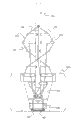
图1是根据本发明实施方式的粉末分配和感测设备的立体图;Figure 1 is a perspective view of a powder dispensing and sensing device according to an embodiment of the present invention;
图2是图1的粉末分配和感测设备的分解图;Figure 2 is an exploded view of the powder dispensing and sensing device of Figure 1;
图3是粉末分配和感测设备的局部竖剖图;Figure 3 is a partial vertical sectional view of the powder dispensing and sensing device;
图3A是粉末分配和感测设备的示意性框图;Figure 3A is a schematic block diagram of a powder dispensing and sensing device;
图4是粉末分配器模块、筒、筒托架和重量传感器单元的立体图;Figure 4 is a perspective view of the powder dispenser module, cartridge, cartridge holder and weight sensor unit;
图5是粉末传送系统的立体图;Figure 5 is a perspective view of the powder delivery system;
图6是阵列组和一个粉末传送系统的截面图;Figure 6 is a cross-sectional view of the array group and a powder delivery system;
图7是筒托架和托架定位系统的截面图;Figure 7 is a cross-sectional view of the cartridge bracket and bracket positioning system;
图8是阵列组的立体图;Figure 8 is a perspective view of the array group;
图9是图8的阵列组的分解图;Fig. 9 is an exploded view of the array group of Fig. 8;
图10是粉末分配器模块的立体图;Figure 10 is a perspective view of a powder dispenser module;
图11是图10的粉末分配器模块的分解图;Figure 11 is an exploded view of the powder dispenser module of Figure 10;
图12是粉末分配器模块下端的示意性截面图;Figure 12 is a schematic cross-sectional view of the lower end of the powder dispenser module;
图13A-13B示出根据本发明一个实施方式的供料杆;13A-13B illustrate a feeder rod according to one embodiment of the invention;
图14A-14F示出根据本发明另一个实施方式的供料杆;14A-14F illustrate a feeder rod according to another embodiment of the present invention;
图15A-15D示出根据本发明又一实施方式的供料杆;15A-15D illustrate a feeder rod according to yet another embodiment of the present invention;
图16A和16B示出分别处于打开和关闭位置的填充阀;Figures 16A and 16B show the fill valve in open and closed positions, respectively;
图17是用于单个粉末分配器模块和重量传感器单元的控制线路的框图;Figure 17 is a block diagram of the control circuitry for a single powder dispenser module and weight sensor unit;
图18是粉末分配过程的流程图;Figure 18 is a flow chart of the powder dispensing process;
图19是筒填充循环的流程图;Figure 19 is a flow diagram of a cartridge fill cycle;
图20是传感器模块的立体图;Figure 20 is a perspective view of the sensor module;
图21是图20的传感器模块的分解图;Figure 21 is an exploded view of the sensor module of Figure 20;
图22是重量传感器探针的第一实施方式的立体图;Figure 22 is a perspective view of a first embodiment of a weight sensor probe;
图23是重量传感器探针的第二实施方式的立体图;Figure 23 is a perspective view of a second embodiment of a weight sensor probe;
图24是粉末曝气机的第一实施方式的立体图;Figure 24 is a perspective view of a first embodiment of a powder aerator;
图25是图24的粉末曝气机的分解图;Figure 25 is an exploded view of the powder aerator of Figure 24;
图26是应用于图24的粉末曝气机中的气动清扫器的立体图;Fig. 26 is a perspective view of the pneumatic sweeper applied in the powder aerator of Fig. 24;
图27是图26的气动清扫器的分解图;Figure 27 is an exploded view of the pneumatic cleaner of Figure 26;
图28A-28C是图24的粉末曝气机的截面图;28A-28C are cross-sectional views of the powder aerator of FIG. 24;
图29是粉末曝气机的第二实施方式的立体图;Figure 29 is a perspective view of a second embodiment of a powder aerator;
图30是图29的粉末曝气机的分解图;Figure 30 is an exploded view of the powder aerator of Figure 29;
图31是应用于图29的粉末曝气机中的气动清扫器的立体图;Fig. 31 is a perspective view of a pneumatic sweeper applied in the powder aerator of Fig. 29;
图32是图31的气动清扫器的分解图;Figure 32 is an exploded view of the pneumatic cleaner of Figure 31;
图33是料斗组件的第一实施方式的立体图;Figure 33 is a perspective view of the first embodiment of the hopper assembly;
图34是图33的料斗组件的分解图;Figure 34 is an exploded view of the hopper assembly of Figure 33;
图35是料斗组件的第二实施方式的立体图;Figure 35 is a perspective view of a second embodiment of a hopper assembly;
图36是图35的料斗组件的分解图;Figure 36 is an exploded view of the hopper assembly of Figure 35;
图37是鼓风机组件的第一实施方式的立体图;37 is a perspective view of a first embodiment of a blower assembly;
图38是图37的鼓风机组件的分解图;Figure 38 is an exploded view of the blower assembly of Figure 37;
图39是鼓风机组件的第二实施方式的立体图;39 is a perspective view of a second embodiment of a blower assembly;
图40是图39的鼓风机组件的分解图;Figure 40 is an exploded view of the blower assembly of Figure 39;
图41是气体调节系统的示意性视图;Figure 41 is a schematic view of a gas conditioning system;
图42是结合有传感器室的粉末输送系统的立体图;42 is a perspective view of a powder delivery system incorporating a sensor chamber;
图43是图42中示出的传感器室的分解图;Figure 43 is an exploded view of the sensor chamber shown in Figure 42;
图44是对吸入筒的填充步骤的图示;Figure 44 is an illustration of the steps of filling the suction cartridge;
图45是对紧凑型吸入器的填充步骤的图示。Figure 45 is an illustration of the filling steps for a compact inhaler.
具体实施方式Detailed ways
图1至图7示出根据本发明一个实施方式的粉末分配和感测设备10。所述设备的目的是将粉末分配进多个筒20中并感测和控制每个筒的填充状态,从而使每个筒容纳精确控制的粉末量。如在此所使用的,术语“筒”是指任意可保持粉末--典型地为包含药物的粉末--的容器或胶囊。如在此所使用的,术语“填充”包括填充和部分填充,因为典型地每个筒没有填充到最大容量而实际上可仅填充到其最大容量的一小部分。如下文所述,所述设备可用于填充吸入筒或者紧凑型吸入器,但是无需限制待填充容器的类型。1 to 7 illustrate a powder dispensing and
筒20可保持在位于托架支撑框架24中的筒托架22中以进行处理。筒可以保持在由行和列构成的阵列中。在一个示例中,筒托架22以6×8的阵列保持48个筒20。筒托架22的构造和设备10的对应构造仅作为示例给出而不是对本发明范围的限制。可以理解筒托架22可构造成保持不同数量的筒,并且在本发明的范围内筒托架22可具有不同的阵列构造。在以下所述的另一个实施方式中,筒托架可保持192个筒。筒托架22可由机器人放置在支撑框架24中和从支撑框架24移走。
除托架支撑框架24外,粉末分配和感测设备10的部件还包括:粉末分配器组件30,其将粉末分配入筒20中;粉末传送系统32,其将粉末输送至粉末分配器组件30;以及传感器模块34,其感测每个筒20的填充状态。粉末分配和感测设备10还包括:框架40,其用于安装托架支撑框架24、粉末分配器组件30、粉末传送系统32和传感器模块34;以及致动器42,其相对于筒20移动粉末分配器组件30和粉末传送系统32。In addition to the
粉末分配器组件30包括:具有竖直孔52阵列的阵列组50;以及安装在阵列组50的每个竖直孔中的粉末分配器模块54。阵列组50可构造成与筒托架22中的筒20阵列或者筒托架中的部分筒相匹配。在上述保持48个筒的筒托架示例中,阵列组50可具有6×8的竖直孔52阵列并提供48个粉末分配器模块54的安装。在这种实施方式中,粉末分配器模块54以1英寸的中心距安装。可以理解可在本发明的范围内利用不同的间距布置。如图8所示,阵列组50还包括粉末存储和传送通道60a、60b、60c、60d、60e、60f、60g和60h,在此实施方式中,一个通道用于每行六个粉末分配器模块54。如下所述,粉末通过粉末传送系统32经由阵列组50中的每个通道输送至粉末分配器模块54。优选地,每个通道具有足够容积以便存储用于数个粉末分配循环的粉末。The
在图1至图7的实施方式中,粉末传送系统32包括:第一粉末传送系统32a,其将粉末输送至阵列组50中的第一组四个通道60a、60b、60c和60d;以及第二粉末传送系统32b,其将粉末输送至阵列组50中的第二组四个通道60e、60f、60g和60h。粉末传送系统32a和32b中的每一个都包括:鼓风机组件70,其使传送气体运动通过粉末传送系统;粉末曝气机72,其将粉末输送至粉末分配器组件30;以及料斗组件74,其向粉末曝气机72供应粉末。在其它实施方式中,可以利用单个粉末传送系统或多于两个的粉末传送系统。In the embodiment of FIGS. 1-7 ,
鼓风机组件70通过管76耦联到粉末曝气机72的气体入口78,并产生通过气体入口78的传送气流。粉末曝气机72包括粉末入口80以接收来自料斗组件74的粉末。粉末由粉末曝气机72经由四个粉末输出口82输送至阵列组50中的各个通道的入口端。粉末经各个通道传送至每行粉末分配器组件30中的粉末分配器模块54。如下所述,粉末通过粉末分配器模块54独立地分配至筒20。
通道60a至60h贯穿阵列组50,并且调整好的吸力歧管84耦联到通道的出口端。第一粉末传送系统32a的吸力歧管84连接到通道60a至60d的出口端,而第二粉末传送系统32b的吸力歧管84连接到通道60e至60h的出口端。吸力歧管84将传送气体返回鼓风机组件70,从而形成闭环式循环气体传送系统。在其它实施方式中,粉末传送系统可利用开环式气体传送系统。任何没有输送至粉末分配器模块54或者存储在通道中的粉末都经由吸力歧管84返回鼓风机组件70。如下论述,在某些实施方式中,鼓风机组件70可包括气体-微粒分离设备以便保留住大粉末结块,同时小粉末结块再循环至粉末曝气机72以输送到粉末分配器组件30。如下进一步论述,每个粉末传送系统可包括气体调节单元以便控制循环传送气体的相对湿度和/或温度。
粉末传送系统32可包括传感器以确定粉末传送系统的不同部件中的粉末高度。料斗组件74可包括料斗高度传感器以感测在料斗组件74的贮槽中的粉末高度。粉末曝气机72可包括放料阀高度传感器以便确定在粉末曝气机72的放料阀中的粉末高度。鼓风机组件70可包括大结块高度传感器。分配器填充高度传感器可置于鼓风机组件70的吸力歧管84处。例如,粉末高度传感器可利用光学技术来感测粉末高度。可利用粉末高度传感器来控制粉末输送系统32的操作以及粉末分配器模块54的粉末加载。
传感器模块34(图20)可包括传感器支架100(图21)和安装在传感器支架100中的传感器组件110的阵列。在示出的实施方式中,每个传感器组件110包括两个传感器单元114(图3)和相关联的电路。因而,一个传感器组件110与两个粉末分配器模块54一起使用。在其它实施方式中,每个传感器组件可包括单个传感器单元或者多于两个的传感器单元。传感器组件110的数量以及传感器组件110在阵列中的布置可使得传感器单元114与位于筒托架22中的筒20的构造或者位于筒阵列中的部分筒的构造相匹配。通过以6×8的阵列、中心距为1英寸地保持48个筒20的筒托架22为例,传感器单元34可包括24个传感器组件110,其在6×8的阵列中以1英寸的中心距提供48个传感器单元114。在图1至图7的实施方式中,每个传感器单元114都是重量传感器,以便感测输送到各个筒20的粉末重量。重量传感器探针112附联到每个传感器单元114并通过筒托架22中的开口与筒20的下端接触。The sensor module 34 ( FIG. 20 ) may include a sensor holder 100 ( FIG. 21 ) and an array of
在粉末分配期间,传感器单元114单独地感测每个筒20的填充状态,使得当所需量的粉末已经分配进每个筒20中时可终止粉末分配。传感器单元114优选为重量传感器,其在粉末分配过程中监控筒20的重量并且在本实施方式中精确到5至10毫克以内。在重量非常小的情况下要求高精度、高速和高重复度的应用中典型地使用电平衡光束作为重量传感器。During powder dispensing, the
重量传感器组件110的物理构造是考虑如下系统的结果:其中粉末分配器模块54例如以1英寸的中心距间隔紧密。优选地,重量传感器组件110可放置在与筒托架22和粉末分配器模块54的构造相匹配的阵列中。在优选实施方式中,传感器组件110具有竖直构造并且两个传感器单元114组合在一起以形成传感器组件。重量感测机械部件位于组件的顶部,电气电路位于机械部件下方并且电连接器位于底部。传感器组件可安装在用于在1英寸中心距的用于重量感测的阵列中。The physical configuration of the
在另一个实施方式中,可购得的重量传感器模块具有一个水平的构造并可在三个不同高度上的分层布置中用于每行具有六个筒的阵列。在分层布置中,使用不同长度的探针与筒接触。In another embodiment, commercially available weight sensor modules have a horizontal configuration and are available in arrays with six cartridges per row in a tiered arrangement at three different heights. In a layered arrangement, probes of different lengths are used to contact the barrel.
粉末分配和感测设备10已经描述为具有以1英寸的中心距安装的粉末分配器模块54和传感器单元114。可以理解在本发明的范围内部件之间可采用更大或者更小的间隔。另外,设备10的部件没必要安装在一致的阵列中。例如,部件之间X方向的间距可与部件之间Y方向的间距不同,或者阵列的行可相对于相邻的行偏移。Powder dispensing and
在操作中,保持筒20的筒托架22优选由机器人或其它自动机构置于托架支撑框架24中。筒托架22下降,从而使得筒20由位于各传感器组件110上的重量传感器探针112从筒托架22抬高并由探针112支撑。筒托架22可在每个筒的位置处设置有开口以允许探针112穿过筒托架22并抬高筒20。因此,每个筒20可由其中一个传感器单元114称重量而没有来自筒托架22的干扰。在某些实施方式中(图22和图23),探针112包括对筒20的三点支撑件。在其它实施方式中,探针112包括对筒20的圆筒形支撑件。粉末分配器组件30下降到分配位置。在分配位置中,每个粉末分配器模块54定位成略高于其中一个筒20且与其对齐。In operation, the
如图2所示,框架40可包括下框架40a、中框架40b、以及上框架40c。下框架40a和中框架40b紧固到基板41。上框架40c为托架支撑框架24、粉末分配器组件30以及粉末传送系统32提供座架。阵列组50连接到致动器42并当致动器42被激励时向上或向下移动。传感器模块34安装在位于下框架40a和中框架40b内的固定位置中。As shown in FIG. 2, the
如下所述,粉末传送系统32可连续操作或间歇操作。起动粉末分配器模块54从而将粉末分配到筒20。粉末分配到筒20是同时进行的,使得所有在筒托架22中的筒或者在筒托架中的部分筒同时接收粉末。随着粉末分配的进行,由各个传感器单元114感测筒20的重量。每个传感器单元114的输出耦联到控制器。如下所述,每个控制器将感测到的重量与对应于所需粉末量的目标重量相比较。只要感测到的重量小于目标重量,则继续粉末分配。当感测到的重量等于或大于目标重量时,控制器命令相应的粉末分配器模块54终止粉末分配操作。如果填充周期之后感测到的重量超出最大允许重量,则相应的筒可标记为不合格。因而,对于在筒托架22中的一批筒而言,粉末分配和重量感测同时进行。批次可包括在筒托架22中的所有筒或者在筒托架中的部分筒。粉末分配周期可包括同时地将粉末分配到一批筒并感测该批次筒的重量,并实现对粉末分配的100%的检测和控制。As described below,
在一个实施方式中,筒在筒托架22中的数量和间隔与设备10中的粉末分配器模块54的数量和间隔相匹配。在其它实施方式中,筒托架的筒数量和筒间距可不同于粉末分配器模块54的构造。例如,筒托架可构造成保持数量成倍于粉末分配器模块54且筒间距小于粉末分配器模块54的间距。仅作为示例,筒托架可构造成保持有以0.5英寸的中心距间隔开的192个筒20。通过这种布置,以0.5英寸的中心距间隔开的筒的12×16的阵列与以1英寸的中心距间隔开的筒的6×8阵列占用的面积相同。In one embodiment, the number and spacing of the cartridges in the
如图7所示,筒托架22可通过托架定位机构120沿水平方向移位以便将不同批次的筒与粉末分配器模块54对齐。筒托架22置于托架支撑框架24中以便处理。托架定位机构120包括耦联到托架支撑框架24的X方向致动器230和耦联到托架支撑框架24的Y向致动器232。因此,托架支撑框架24和筒托架22可沿水平X-Y平面移动,从而相对于粉末分配器模块54和传感器单元114定位这些批次的筒。As shown in FIG. 7 , the
具有192个筒的筒托架可如下地处理。筒托架从空档位置移至第一X-Y位置(0,0),从而使得第一批48个筒与48个粉末分配器模块54的阵列竖直对齐。粉末分配进第一批筒中,然后筒托架移至第二X-Y位置(0,0.5)以便将第二批48个筒与48个粉末分配器模块54的阵列对齐。粉末分配进第二批筒中,然后筒托架移至第三X-Y位置(0.5,0)以便将第三批48个筒与48个粉末分配器模块54的阵列对齐。然后筒托架移至第四X-Y位置(0.5,0.5)以便将第四批48个筒与48个粉末分配器模块54的阵列对齐。粉末分配进第四批筒中从而完成192个筒的处理。在以上示例中,托架定位顺序和筒的批次顺序可变化。A cartridge rack with 192 cartridges can be handled as follows. The cartridge carriage is moved from the neutral position to the first X-Y position (0,0) such that the first batch of 48 cartridges is vertically aligned with the array of 48
可以理解这种处理可应用于具有不同筒间距、不同筒数量等的不同托架布置。在这些实施方式中,筒托架在水平平面内移位以获得分批的筒与粉末分配器模块的阵列之间的对齐。批次的筒典型地与粉末分配器模块54的阵列相配。然而,在某些应用中,批次中筒的数量可少于粉末分配器模块的数量。It will be appreciated that this process is applicable to different carriage arrangements with different cylinder pitches, different numbers of cylinders, and the like. In these embodiments, the cartridge holders are displaced in a horizontal plane to achieve alignment between the batched cartridges and the array of powder dispenser modules. A batch of cartridges is typically fitted with an array of
在图8和图9中示出阵列组50。如上所述,阵列组50设置有粉末存储和传送通道60a、60b、60c、60d、60e、60f、60g和60h,一个通道对应于粉末分配器模块54阵列中的每一行。每个通道60a至60h延伸贯穿阵列组50且与阵列相应行中的竖直孔52相交。在图1至图7的实施方式中,粉末传送系统32a将粉末输送至阵列组50的一侧,同时粉末传送系统32b将粉末输送至阵列组50的相反侧。因此,图8和图9示出通道60a至60d的进口端和通道60e至60h的出口端。The
在图8和图9的实施方式中,通道60a至60h的截面呈长孔形并平行。如图10所示,每个粉末分配器模块54都设置有呈贯穿粉末分配器模块的长孔形开口形式的粉末入口130。当粉末分配器模块54安装在阵列组50中时,粉末入口130与阵列组50中的相应通道对齐。粉末入口130和通道60a至60h优选具有相同尺寸和形状的截面并经过抛光以提供光滑的内表面。阵列组50中的每个通道和粉末分配器模块54中相应的粉末入口130限定一个贯穿阵列组50以用于将粉末输送至每个粉末分配器模块54的通路。粉末经粉末入口130供应到每个粉末分配器模块54。粉末入口130构造成贯穿开口,以使得一部分经通道传送的粉末输送至第一粉末分配器模块54而另一部分粉末经粉末入口130和阵列组50中的通道传送至后续的粉末分配器模块54。In the embodiment of FIGS. 8 and 9 , the cross-sections of the
另外,通道60a至60h起储存粉末的作用。通道60a至60h可存储的粉末多于分配到单批次筒所需的粉末。在一个实施方式中,粉末传送系统32间歇地操作。用于多批次筒20的足量粉末从料斗组件74供应到通道60a至60h。然后,粉末被分配到多批次筒20,直至分配器模块54中的粉末供应变得不足。在其它实施方式中,粉末连续供应到通道60a-60h,并且通道60a至60h作为缓冲器以存储未分配到筒20的粉末。In addition, the
闭环式气动粉末传送系统32将结块颗粒从粉末曝气机72馈送入阵列组50中。然后,传送气体循环回到粉末曝气机72。传送气体可通过供应到鼓风机组件70的次级处理控制气体调节。The closed loop pneumatic
阵列组50起动态粉末储存设备的作用,其将药粉的批次载量或连续载量馈送入单个粉末分配器模块54中。更一般地,阵列组50包括一个或多个用于将药粉的粉末气雾和/或结块浆料传送到粉末分配器模块阵列的通道。阵列组50可在开环式或闭环式气体传送系统中操作。粉末曝气机72和阵列组50将药粉流化、夹带并传送进阵列组50的通道中。The array set 50 functions as a dynamic powder storage device that feeds batch loads or continuous loads of medicament powder into a single
阵列组50可为例如粉末曝气机72、料斗组件74、吸力歧管84以及泵组件70等相关联的部件和子系统供给主要的结构支撑。另外,阵列组50保持用于将粉末分配到筒阵列的粉末分配器模块54的阵列。在一个优选实施方式中,阵列组50包括主体132、顶板134以及底板136。板136和板136包括作为用于粉末分配器模块54的导向件和密封件的O形环。此阵列组还包括支承件140及用于将阵列组附连到框架构件的夹柄142。Array set 50 may provide primary structural support for associated components and subsystems such as
在操作中,在受控的颗粒沉降过程中,粉末由传送气体经每个通道60a至60h传送并输送到每个粉末分配器模块54。粉末通过重力作用落入每个粉末分配器模块54中。任何穿过通道而未落入粉末分配器模块54之一中且未被存储的粉末通过吸力歧管84返回泵组件70。In operation, powder is conveyed by conveying gas through each
每个粉末分配器模块54将粉末分配进筒20中。粉末的剂量典型地在5至30毫克范围内,但是剂量不限于该范围。Each
如在图10至图16B中详细示出,粉末分配器模块54包括具有下支架部分150a、中支架部分150b和上支架部分150c以及罩盖150d的粉末分配器支架150。粉末分配器支架150可呈长形构造,具有小的截面以允许在阵列组50中的紧密间距。如上面指出的,粉末分配器模块54可以1英寸的中心距安装。中支架部分150b包括粉末入口130和圆筒形导管152,其从粉末入口130向下延伸至下支架部分150a。下支架部分150a包括向下延伸到分配器管嘴158的锥形导管154,分配器管嘴的尺寸大小与筒20相适应。可呈圆锥形的锥形导管154提供从圆筒形导管152的尺寸到分配器管嘴158的尺寸的过渡。圆筒形导管152和锥形导管154共同限定用于保持待分配粉末的分配器料斗156。分配器料斗156中的粉末称为散装粉末层。分配器管嘴158构造成将粉末分配进筒20中。As shown in detail in FIGS. 10-16B , the
粉末分配器模块54还包括:以受控方式使粉末经料斗156向下移至管嘴158的供料杆160;致动杆160的杆致动器162;位于料斗156下端的分配器填充阀180;以及打开和关闭阀180的阀致动器182。杆致动器162和阀致动器182可为微型马达。杆致动器162可通过柔性耦联件186或其它耦联件耦联到供料杆160,所述其它耦联件除转动供给旋转外还可提供竖直的杆搅动、位移或二者兼有。粉末分配器模块54还包括电路板184,该电路板184的电路用于控制杆致动器162和阀致动器182并用于与控制粉末分配器模块54操作的控制电路连通。The
填充阀180可包括实施为齿轮的阀构件190,阀构件190设置有偏心设置的阀开口191。阀构件190可安装在下支架部分150a中以用于绕一个轴线旋转,使得阀开口191可如图16A所示转入与分配器管嘴158对齐的位置并可如图16B所示转出与分配器管嘴158对齐的位置。当阀开口191与分配器管嘴158对齐或部分对齐时,填充阀180打开且粉末分配到筒内。当阀开口191不与分配器管嘴158对齐时,填充阀180关闭且粉末不分配。优选地,如下所述,填充阀180为可部分打开的类型。The filling
填充阀180的阀构件190可通过驱动组件耦联到阀致动器182,驱动组件包括:与阀构件190的齿轮啮合的下齿轮192;从分配器模块54的下部延伸至分配器模块上部--阀致动器182安装于此上部处--的驱动轴193;附连到驱动轴193上端的上齿轮194;以及附连到阀致动器182的上齿轮195。上齿轮194和195集成一体以使得当激励阀致动器182时导致阀构件190旋转。The
齿轮195可与阀构件190相匹配,同时齿轮194可与齿轮192相匹配。因此,齿轮195的位置指示阀构件190的位置以及阀开口191相对于管嘴158的位置。附连到上齿轮195的磁体相对于开/关传感器220(图17)旋转以分别指示填充阀180的打开和关闭位置。
在图12中示出位于粉末入口130和分配器管嘴158之间的粉末分配器模块54的下端的示意性截面图。如图所示,可认为分配器料斗156具有粉末层准备区156a、粉末层压缩区156b、以及排出区156c。粉末层准备区156a位于粉末入口130下方的圆筒形导管152中。粉末层压缩区156b位于锥形导管154的上部中,而排出区156c位于锥形导管154的下部中。A schematic cross-sectional view of the lower end of the
供料杆160可包括轴向贯穿分配器料斗156延伸的杆形式的轴杆170。供料杆160还包括一个或多个附接到轴杆170的供料元件。供料元件以受控方式将粉末从粉末入口130移至分配器管嘴158。在图12的实施方式中,供料杆160包括:位于粉末层准备区156a中的粉末层准备元件164;位于粉末层压缩区156b中的粉末层压缩元件165;以及位于排出区156c中的排出元件166。下面描述供料元件164、165和166的示例。The
在图13A和图13B中示出供料杆160的一个实施方式。在此描述的供料杆实施方式中,粉末层准备元件164和粉末层压缩元件165实施为螺旋式敞开框架,包括:多个安装到轴杆170上的间隔开的桁架172;以及一个或多个附接到桁架172和轴杆170的线。桁架172可在圆筒形导管152和锥形导管154中从轴杆170径向延伸。桁架172可延伸到料斗156内壁附近但不接触该内壁。在锥形导管154中的桁架172长度变化以与锥形导管154的圆锥形内壁相配。桁架沿不同径向安装到轴杆170上。在优选实施方式中,桁架172的端部限定一个双螺旋。One embodiment of a
在图13A和图13B的实施方式中,供料杆160包括10个桁架。在这一示例中,相邻桁架以0.125英寸的间距沿轴杆170分隔开,并且除在轴杆170底部的最后两个转动22.5度的桁架外,每个桁架都相对于相邻桁架转动45度。桁架的直径可优选地为结块的尺寸,大致为0.025英寸至0.075英寸。桁架材料可为不锈钢或其它结构刚性、耐腐蚀的惰性材料--例如金属、陶瓷、塑料等。根据粉末的形态,供料杆可由导电或非导电材料制成。可将例如陶瓷、塑料以及弹性体的非导电材料镀上金属以提供导电的外表面。桁架过多导致粉末与旋转的杆挤压,反之桁架过少就不能支撑双螺旋构造。桁架的间距和相邻桁架的夹角可与使用的桁架数量成反比。In the embodiment of Figures 13A and 13B, the
如上面指出的,供料杆160包括附接到桁架172的线。在图13A和图13B的实施方式中,线限定双螺旋174、第一V形176和第二V形178。如图所示,双螺旋174包括位于或靠近每个桁架172一端的螺旋线174a和位于或靠近每个桁架172相反端的螺旋线174b。当从杆致动器162向下观察时每个螺旋线174a、174b从桁架到桁架沿顺时针方向向下前进。As noted above,
第一V形176可包括在距离轴杆170的第一间隔处附接到桁架172的第一V形线176a,而第二V形178可包括在距离轴杆170的第二间隔处附接到桁架172的第二V形线178a。第一V形线176a穿过轴杆170中的孔176b,而第二V形线178a穿过轴杆170中的孔178b。可以理解,螺旋线和V形线无需附接到供料杆160中的每个桁架。特别地,第一V形线176a附接到第一桁架(最高的桁架)和第五桁架。第二V形线178a附接到第三桁架和第七桁架。第一和第二V形可彼此隔开90°。The first V-
在图13A和13B的实施方式中,螺旋线和V形线旋拧穿过位于各桁架中的孔并附连于各端部处。螺旋线位于桁架的端部处或端部附近,而V形线位于和轴杆170隔开期望间距处。桁架172中的孔可通过刀具钻孔、激光钻孔或放电钻孔。在一个优选的实施方式中,桁架172中的孔通过放电钻孔,其钻孔角度防止线的显著弯曲。从而,每个桁架中的孔与相邻桁架大致对齐。这种布置使得线可以大致自由地滑经孔,使得粉末装载力沿整个线的长度分布,从而减少可能导致断裂的线应力集中。在其它的实施方式中,线可例如通过激光焊接附连于桁架。在此示例中,螺旋线和V形线的直径为0.008英寸。In the embodiment of Figures 13A and 13B, the helix and V-shaped wires are threaded through holes in each truss and attached at each end. The helix is located at or near the end of the truss, while the V-shaped wire is located at a desired spacing from the
双螺旋174可通过以螺旋线174a和174b绑系螺旋式安装的桁架172的外端来形成。在桁架172的两个外端布线以形成双螺旋线图案。双螺旋线图案执行三个主要功能。首先,周边的线阻止被压缩粉末粘附于导管壁、尤其是锥形导管154的壁。第二,当杆160顺时针旋转(从致动器杆朝下观察)时,双螺旋抬高位于导管壁界面处的粉末,并进一步将其减小到优选的可流动结块的尺寸范围。第三,当杆160逆时针旋转时,双螺旋沿轴杆170、以及沿V形线自由路径向下供给散装粉末,并将粉末供给到分配器管嘴158中。另外,这个旋转的散装粉末供给操作易于粉碎水平地形成于旋转桁架172之间的压缩粉末饼。
供料杆160利用螺旋形的敞开框架,该框架如上所述地包括作为中央支撑件的轴杆170、作为结构横向构件形成具有锥形渐缩下端形状的螺旋形图案的桁架172、以及形成双螺旋174及第一和第二V形176和178的线。倒锥形将桁架从较大直径的导管过渡到较小直径的粉末排出管嘴。线附接到桁架以减少散装粉末的压缩效果、及改善结块浆料的流动。供料杆160能够以微克的精度传送高粘性的粉末,同时控制散装粉末被压实的倾向。粉末压实导致粉末压缩锁住,并从而导致分配器堵塞。螺旋形敞开框架提供一种有利的散装粉末传送构件,其能够精确地传送和分配各种形态的粉末--从自由流动到高粘度。通过仅允许小部分的螺旋机械力沿向下方向进入散装粉末层内、从而与待分配粉末的个体特性相适应地控制压缩效果来获得这种性能。由于此压缩控制,可有效地将粘性的粉末从大直径导管传送到小直径导管内。The
轴杆170形成供料杆160的中央驱动轴杆。轴杆170支撑桁架172、双螺旋174和第一及第二V形176及178,这从而传送散装粉末以进行精确分配。中央驱动轴杆允许细小粉末沿其光滑的表面朝分配器管嘴158流动。
桁架172为粉碎被压实的粉末结块层的结构横向构件。桁架172还支撑螺旋及V形线。另外,桁架172提供以受控、低压缩的方式传递散装粉末层所需的螺旋机构。
V形线176a和178a提供散装粉末层内的切割图案。线设置成减少被压实的粉末并打开一个位于粉末层内的临时自由路径,该自由路径允许少量的粉末结块在重力作用下向下流动通过粉末层。另外,V形线切断形成于桁架172之间的散装粉末饼。这些饼由累积的压实力形成并形成悬置的结块粉末结构。通过优选地在中间处切断饼,饼的结构变得不稳定,并在来自螺旋桁架172的机械力的驱动下开始粉碎和向下流动。V-shaped
排出元件166(图12)构造和设置成粉碎位于分配器管嘴158处的粉末压缩饼。当填充阀180关闭且杆160执行散装粉末的耙整和梳理操作时形成粉末饼。如果排出元件166不移除和减少饼的话,则饼将堵塞管嘴或在阀打开时掉入筒内,可能导致筒的过量填充。在环境湿度大于50%时,粉末饼堵塞管嘴的可能性最大。The discharge element 166 ( FIG. 12 ) is constructed and arranged to break up the compressed cake of powder located at the
在图13A-13B、14A-14F和15A-15D中示出了排出元件166的实施方式。每个实施方式都采用如上所述的由桁架及线形成的螺旋型敞开框架,但是采用不同的排出元件。通过旋转上述的螺旋型敞开框架,粉末受导引落入粉末层准备区156a中。外侧螺旋线破坏粉末与圆筒形导管壁之间的吸力,并在反向旋转时抬高粉末层并给粉末层曝气。随着螺旋型敞开框架的旋转,V形线切割并进一步减少粉末层。粉末层准备区156a增加了粉末层在进入粉末层压缩区156b的锥形导管时的流动性。因为螺旋型敞开框架能够形成自然结块--其在受到螺旋型敞开框架的力的引导时允许粉末流动,所以增强了粉末的流动性。在粉末层压缩区156b中,结块粉末层因为锥形导管的体积减少而受到压缩。压缩区不断地增强粉末层的压实,同时桁架和线持续地减少和曝气粉末层。在排出区156c中,粉末结块团进一步减少并通过管嘴158排出。排出元件控制粉末的减少和分配特性。粉末减少控制的不足导致排出孔口堵塞。粉末减少控制的不足还阻碍了粉末在规定时间内的不过量分配。排出元件确定最终的粉末分配流速以及粉末结块的一致性。Embodiments of the
在图13A-13B所示的实施方式中,排出元件166构造成改型桁架181。改型桁架181的两侧181a和181b向下延伸半个逆时针螺旋圈以形成一个双螺旋。双螺旋改型桁架181和双螺旋174反向地盘绕。在其它实施方式中,改型桁架的一侧螺旋形地向上转。改型桁架可形成顺时针或逆时针的螺旋。在某些实施方式中,改型桁架可形成为倒U形或S形。对于自由流动的粉末,U形效果较好;而对于粘性粉末而言S形效果较好。在U形中,改型桁架的两侧都转向分配器管嘴。在S形中,改型桁架的一侧转向分配器管嘴而另一侧向上转。In the embodiment shown in FIGS. 13A-13B , the
图13A-13B的双螺旋改型桁架181起到位于锥形导管下端内的旋转极化元件的作用。改型桁架的反向盘绕几何形状增加了粉末的抬升和曝气,从而控制粉末分配以及改善了粉末的一致性。反向盘绕几何形状还在耙整循环中将粉末驱往管嘴。这形成了分配循环开始时的初始的2到4毫克的粉末排卸,并最终获得更多的填充时间。The double helix modified
在图14A-14F中示出了供料杆160的另一实施方式。在图14A-14F的实施方式中,排出元件166实施为通过倒U形支撑元件185安装于轴杆170的滚针183。在图14A-14F的实施方式中,可选地,开有多个槽的挡盘189可位于锥形导管154的上部并附接到下支架部分150a。Another embodiment of a
粉末分配器模块54进一步包括安装于锥形导管154下部的孔口元件187。孔口元件187可具有一个或多个槽形的孔口。在图14D所示的一个实施方式中,孔口元件187a包括两个相交形成十字的槽形孔口。在其它实施方式中,孔口元件187b和187c包括三个相交的槽形孔口,如图14E和14F所示。孔口可以相对较宽,如图14E所示,或者可以相对较窄,如图14F所示。供料杆160定位成使得滚针183与孔口元件187隔开的间距小于自然的结块尺寸。在操作中,滚针183相对于孔口元件187旋转,使得粉末通过孔口元件187中的孔口排出。The
挡盘189可用于控制粉末层的前进速度,并且用于进一步减少进入锥形导管时的粉末结块。在排出区156c中,粉末结块团减少并然后由旋转的滚针183通过孔口元件187中的孔口挤出。包括支撑元件185、滚针183和孔口元件187的机构控制粉末的减少和分配特性。粉末减少控制的不足导致排出孔口堵塞。粉末减少控制的不足还阻碍了粉末在规定时间内的不过量分配。支撑元件185和滚针183确定最终的粉末分配流速和粉末结块的一致性。包括支撑元件185、滚针183和孔口元件187的机构可构造成为特定的粉末形态提供最佳的粉末流动及结块尺寸。支撑元件185沿下支架部分150a的周边槽道行进以自动对中供料杆160。与孔口元件187结合的滚针183实现了力很小的粉末结块分配。孔口元件187提供了一致的粉末结块,结块尺寸落在一个很小的范围内。The
在图15A-15D中示出了供料杆160的另一个实施方式。排出元件166实施为附接于轴杆170的螺旋形的螺旋刀片240和242。每个螺旋刀片240、242绕轴杆170转大约半圈。螺旋刀片240和242的轴向长度可以是锥形导管154的轴向长度的大约一半。如图所示,图15A-15D所示的供料杆所采用的桁架少于图13A-13B的实施方式,而螺旋线和V形线可附接于螺旋刀片240和242的上边缘。螺旋刀片240、242以及双螺旋174可反向地盘绕。Another embodiment of a
图15A-15D所示的粉末分配器模块54进一步包括安装于锥形管道154下端的孔口元件244。在图15A-15D所示的实施方式中,孔口元件244呈倒锥形,并设置有用于通过管嘴158排出粉末的多个孔口244a。进一步地,螺旋刀片240和242的下边缘是倾斜的,从而与倒锥形孔口元件244相匹配。安装于轴杆170下端的轴承246接合孔口元件244中的开口并形成螺旋刀片240、242与孔口元件244之间的期望间距。轴承246可以是例如红宝石或蓝宝石的宝石材料,其对分配的药粉不形成污染。在操作中,螺旋刀片240和242相对于孔口元件244旋转,导致粉末通过孔口元件244中的孔口排出。在其它的实施方式中,孔口元件可以是平的,如图14D-14F所示,且螺旋刀片240和242的下边缘是平的,以与孔口元件相匹配。The
此实施方式与图13A-13B和14A-14F中所示的供料杆反向地旋转。在排出区156c中,反向盘绕的螺旋刀片导致粉末结块流动、并然后被挤出、由旋转的螺旋尖经由孔口元件244中的孔口粉碎成颗粒状。螺旋刀片和孔口元件形成的机构控制粉末的减少及分配特性。粉末减少控制的不足导致排出孔口堵塞。粉末减少控制的不足还阻碍了在规定时间内的不过量分配。由螺旋刀片240、242及孔口元件244形成的机构能够补偿粉末层的流体落差高度,从而降低分配过程对粉末层落差状况的敏感度。螺旋刀片的半圈双螺旋使得管嘴中的粉末不受竖直流体层力的作用,从而消除倾向于将粉末压紧在管嘴中的力矢量。由螺旋刀片240、242及孔口元件244形成的机构可构造成提供最佳的单一粉末结块尺寸。该机构提供了一致的粉末结块,结块尺寸落在一个很小的范围内。轴承246提供螺旋的对齐和支撑,同时保持从螺旋到孔口的粉末薄膜的厚度。This embodiment rotates counter to the feeder rod shown in Figures 13A-13B and 14A-14F. In the discharge zone 156c, the counter-coiled helical blades cause a flow of powder agglomerates and are then extruded, broken into granules by the rotating helical tip through the orifice in the
在某些实施方式中,排出元件166安装在位于轴杆170尖端内的孔中。在其它的实施方式中,排出元件166实施为轴杆170的可拆除的尖端。例如,双螺旋排出元件可形成为压配合到轴杆170端部中的可拆除尖端。可以更换该可拆除尖端以适应不同的粉末形态。In certain embodiments, the
下文参见图13A-13B和14A-14F的实施方式的耙整操作和分配操作来描述粉末分配器模块54的操作。耙整是这样的一种操作:将粉末层梳理和调整成均匀地曝气、具有有利结块尺寸的基体,从而为散装粉末传送提供更高的流动性。优选的结块尺寸是通过粉末层翻滚操作所形成的粘性粉末结块的自然、稳定的尺寸,并且其球径通常落在0.025英寸到0.075英寸的范围内。粉末层耙整可通过向下进刀或抬升的模式进行。然而,粘性粉末偏向于抬升耙整以实现最佳的曝气及改善的流动性。分配是将干燥散装粉末以“洒落”方式传送的操作,在重力作用下无压缩地掉落,优选的结块基体从粉末管嘴排出、分配入筒内。在此描述的粉末分配和感测设备可以操作球径范围在0.005英寸到0.075英寸的粉末结块,但是并不限于这个范围。Operation of the
当从分配器模块54的顶部观察时,供料杆160沿顺时针方向转动以对散装粉末层进行耙整、梳理和曝气。由于双螺旋导致的向上流动矢量,顺时针旋转抬升粉末。在此操作中,杆可以看作一个螺丝,竖直地保持在其螺帽处、被转入粉末内。双螺旋刮擦导管壁,并且还将外侧结块移向分配器料斗的中央。随着杆的转动,桁架迫使大的结块均匀地粉碎。这对散装粉末层进行曝气,导致层更为一致。When viewed from the top of the
为了分配粉末,杆160优选地沿逆时针方向转动。桁架172和V形176、178粉碎粉末层并打开一个自由路径,使得粉末沿轴杆170流动。双螺旋174附加一个下压矢量来向下驱动粉末并通过分配器料斗158。在其它的实施方式中,杆160沿顺时针方向转动以分配粉末。然而,结块易于变大,并且对于沿顺时针方向旋转的粉末分配而言,过量填充的可能性要大得多。To dispense the powder, the
在上述的实施方式中,当从顶部观察时,桁架和螺旋线具有顺时针的构造。应当理解,在本发明的范围内,供料杆的桁架及线的布置可以反过来。从而,当从顶部观察时,桁架及螺旋线可具有逆时针的构造。在这个构造中,杆优选地沿顺时针方向旋转以分配粉末。In the embodiments described above, the trusses and helixes have a clockwise configuration when viewed from the top. It should be understood that the arrangement of the trusses and wires of the feeder bars could be reversed within the scope of the present invention. Thus, the trusses and helixes may have a counterclockwise configuration when viewed from the top. In this configuration, the lever rotates preferably in a clockwise direction to dispense the powder.
下文对粉末分配器模块54的操作的描述参见图15A-15D的实施方式的耙整操作及分配操作。当从分配器模块54的顶部观察时,供料杆160沿逆时针方向旋转以梳理散装粉末层并填充螺旋。双螺旋174附加一个下压矢量来向下驱动粉末并进入分配器管嘴158。同时,螺旋刀片240、242在粉末上施加向上的力矢量,以使得螺旋中的粉末升到上层以进行曝气。The following description of the operation of the
为了分配粉末,供料杆160优选地沿顺时针方向转动。由于螺旋形敞开框架的双螺旋导致的向上的流动矢量,顺时针转动抬高上层粉末。在此操作中,上部的杆可看作一个螺丝,竖直地保持在其螺帽处、被转入粉末内。双螺旋刮擦导管壁,并且还将外侧结块移向分配器料斗的中央。随着杆的转动,桁架迫使大的结块均匀地粉碎。这对散装粉末层进行曝气,导致层更为一致。桁架172和V形176、178粉碎粉末层并打开一个自由路径,使得粉末沿轴杆170流动。To dispense the powder, the
在首先开始分配时,螺旋中的粉末因为螺旋的向下力矢量受迫通过管嘴。在分配期间,另外的粉末通过从上层掉落的曝气粉末来供应。When dispensing first begins, the powder in the auger is forced through the nozzle by the downward force vector of the auger. During distribution, additional powder is supplied by aerated powder falling from the upper deck.
在上述的实施方式中,当从顶部观察时,桁架和螺旋线具有顺时针的构造。应当理解,在本发明的范围内,供料杆的桁架及线的布置可以反过来。从而,当从顶部观察时,桁架及螺旋线可具有逆时针的构造。在这个构造中,杆优选地沿逆时针方向旋转以分配粉末。In the embodiments described above, the trusses and helixes have a clockwise configuration when viewed from the top. It should be understood that the arrangement of the trusses and wires of the feeder bars could be reversed within the scope of the present invention. Thus, the trusses and helixes may have a counterclockwise configuration when viewed from the top. In this configuration, the lever rotates preferably in a counterclockwise direction to dispense the powder.
在图17中示出用于单个粉末分配器模块54及对应的传感器单元114的控制器的框图。优选地,粉末分配器的控制提供最低程度的有目的的集中冗余计算能力。粉末分配器模块54包括位于电路板184(图11)上的分配器控制器200(图17)。分配器控制器200可包括三个处理器。每个杆致动器162和阀致动器182设置一个处理器,且一个处理器用于控制状态LED 224和可选模拟传感器输入。控制处理器210位于传感器模块34的底板上,如下文所述。该系统对每个分配器模块54及其相应的传感器单元114采用一个控制处理器210。处理器210控制传感器模块34和分配器模块54之间的通讯以及外部通讯。当给出填充参数以及“执行”指令时,控制处理器210具有读取传感器单元并指令分配器模块致动器执行筒的填充的能力。控制处理器210还与管理处理器212通过网络界面进行通讯。管理处理器212对所有的粉末分配器模块和传感器单元提供高级别的控制。A block diagram of a controller for a single
除了管理处理器之外,系统中的每个分配器模块54及相应的传感器单元114都重复图17的控制器。在上述6×8的分配器模块阵列的示例中,系统包括48个控制器。此布置提供对每个筒的粉末分配的独立控制和监控。With the exception of the management processor, each
在一个实施方式中,构造和控制粉末分配器模块54,从而在10秒钟内精确地分配10.0mg(毫克)的粉末。平均流速为1.0mg每秒,精度为+/-0.3mg或3%。为了以这个流速填充,控制电路每秒钟至少作出20个决定。在其它的实施方式中,为了获得期望的精度,控制电路每秒钟作出多于或少于20个的决定。供料杆的几何形状提供了足够的流动一致性以实现此性能。供料杆将粉末团粉碎成小的结块颗粒。机械地供料的结块浆料的流动特性允许粉末在供料杆停止时暂停、同时粉末溢出最少,粉末溢出可能会导致筒的过量填充。In one embodiment, the
控制电路可提供下列的控制和功能。The control circuit provides the following controls and functions.
1.杆速可具有50种不同的速度,从0.1转每秒变到5转每秒。1. Rod speed can have 50 different speeds, from 0.1 rpm to 5 rpm.
2.在填充时,杆可以脉动。在脉动时,杆交替地顺时针旋转然后逆时针旋转,例如前进两步/后退一步,运动方式基于编程的脉动系数。当填充重量小于选定的重量时,“脉动小于重量”的功能与脉动接合。当填充重量大于选定的重量时,“脉动大于重量”的功能与脉动接合。当填充重量位于两个选定的重量之间时,“中间脉动”的功能与脉动接合。脉动指数是脉动时的选择转速。脉动重量是选定的开始或停止脉动的重量,且可以选择在选定的脉动重量处的最小脉动时间。在某些应用中,可能不采用脉动。2. While filling, the rod can pulse. While pulsating, the rod rotates alternately clockwise and then counterclockwise, eg two steps forward/one step back, in a motion pattern based on the programmed pulsation coefficient. The "pulse less than weight" feature engages pulsation when the fill weight is less than the selected weight. The "pulse over weight" feature engages pulsation when the fill weight is greater than the selected weight. The "Intermediate Pulse" function engages the pulse when the fill weight is between two selected weights. The pulsation index is the selected speed when pulsating. The pulse weight is the selected weight to start or stop pulsing, and optionally a minimum pulse time at the selected pulsating weight. In some applications, pulsation may not be used.
3.控制电路可打开和关闭粉末分配器填充阀。3. The control circuit can open and close the powder dispenser filling valve.
4.控制电路可测量传感器单元的皮重并开始粉末分配循环,以及可以停止粉末分配循环。4. The control circuit can measure the tare weight of the sensor unit and start the powder dispensing cycle, and can stop the powder dispensing cycle.
5.控制电路可通过由耙整时间、脉动时间和速度限度的序列来耙整粉末分配器中的粉末。5. The control circuit can rake the powder in the powder dispenser through a sequence consisting of rake time, pulse time and speed limit.
6.新的装载函数开始通常在用新鲜粉末装载分配器模块之后运行的耙整/脉动循环。规定耙整时间、脉动时间以及速度。6. The new load function starts the rake/pulse cycle that normally runs after loading the dispenser module with fresh powder. Specify rake time, pulse time and speed.
7.另外的功能包括在填充循环期间自动地打开和关闭填充阀、每次阀关闭时自动地耙整粉末、以及在每次阀关闭时的耙整之后自动地脉动粉末。7. Additional features include automatically opening and closing the fill valve during the fill cycle, automatically raking the powder each time the valve closes, and automatically pulsing the powder after each rake when the valve closes.
8.“停止步骤”函数设定在达到目标重量后反向旋转供料杆的步骤数。这可以使粉末回流以防止过量填充,并取决于粉末形态的类型和相关的环境湿度条件。8. The "Stop Steps" function sets the number of steps to counter-rotate the feed rod after reaching the target weight. This allows the powder to reflow to prevent overfilling and depends on the type of powder form and the associated ambient humidity conditions.
9.速度控制函数迫使供料杆全速地运行,直至达到选定的填充重量。在这个触发点,开始比例控制以与目标重量减去实际重量成比例地减少杆速。此方法减少了总的填充时间。对于10mg的额定填充重量以及+/-3%的公差而言,落在10.3mg到9.7mg之间的任何填充重量都是可接受的。由于过量填充的筒必须被扔掉,所以在达到最小重量之后,填充尽可能早地停止以避免可能的过量填充。最小重量例如设为9.75mg,略大于实际的下限9.7mg。这是必要的,因为当粉末掉落到筒内时,附加的力--例如惯性力、气动力、静力以及磁通量--可导致瞬间的重量读数略高于实际的粉末重量。在一个数十秒的短暂时间之后,读数停留在实际重量上。将最小重量设成高于实际下限0.05mg减少了筒填充不足的危险。9. The speed control function forces the feed rod to run at full speed until the selected fill weight is reached. At this trigger point, proportional control is initiated to reduce rod speed in proportion to target weight minus actual weight. This method reduces the overall fill time. For a nominal fill weight of 10 mg and a tolerance of +/- 3%, any fill weight falling between 10.3 mg and 9.7 mg is acceptable. Since the overfilled cartridge has to be thrown away, filling is stopped as early as possible after the minimum weight is reached to avoid possible overfilling. The minimum weight is set at, for example, 9.75 mg, which is slightly larger than the actual lower limit of 9.7 mg. This is necessary because as the powder falls into the barrel, additional forces—such as inertial, aerodynamic, static, and magnetic flux—can cause momentary weight readings to be slightly higher than the actual powder weight. After a brief period of tens of seconds, the reading stays at the actual weight. Setting the minimum weight 0.05 mg above the practical lower limit reduces the risk of underfilling the cartridge.
10.与填充循环相关联的参数包括填充伺服回路的比例增益、例如在比目标重量低1.0mg时启动的填充伺服回路的积分增益、以及填充循环期间所允许的最大杆速。可通过将速度指数规定在0到50之间来控制杆速。作为杆速指数的函数的、以每秒几转为单位的杆速的特性在于:其对于低的杆速指数而言大致呈线形,并然后急剧地增加到最大杆速。此特性提供在较低速度时比较高速度时更精细的控制,并允许杆在起初的70%的填充循环内迅速得多地运行,以迅速地将筒填充到其填充重量的90%。最大杆速通常为5转每秒。超过该速度,存在将粉末压得如此地实、从而使得必须卸下并清理分配器以恢复原来的粉末流动特性的危险。10. Parameters associated with the fill cycle include the proportional gain of the fill servo loop, the integral gain of the fill servo loop activated eg at 1.0 mg below target weight, and the maximum rod speed allowed during the fill cycle. Stick speed can be controlled by setting the speed index between 0 and 50. The characteristic of the rod speed in revolutions per second as a function of the rod speed index is that it is approximately linear for low rod speed exponents and then increases sharply up to the maximum rod speed. This feature provides finer control at lower speeds than at higher speeds and allows the rod to travel much more rapidly during the first 70% fill cycle to quickly fill the cartridge to 90% of its fill weight. The maximum rod speed is typically 5 revolutions per second. Above this speed, there is a danger of compacting the powder so strongly that the dispenser must be removed and cleaned to restore the original powder flow characteristics.
脉动系数控制供料杆旋转时的往复运动--如果允许脉动。在此实施方式中,向前旋转与退后旋转的比例是2。从而,取决于脉动系数,供料杆向前旋转2n步并退后旋转n步。从而,例如500的脉动系数表示前进1000步并后退500步,而1的脉动系数表示前进2步并后退1步。在其它的实施方式中,向前旋转与退后旋转的比例的值可不等于2和/或可编程。The pulsation factor controls the reciprocating motion of the feed rod as it rotates -- if pulsation is allowed. In this embodiment, the ratio of forward rotation to backward rotation is two. Thus, depending on the pulsation coefficient, the feed rod rotates 2n steps forward and n steps backward. Thus, for example, a pulsation factor of 500 means 1000 steps forward and 500 steps back, while a pulsation factor of 1 means 2 steps forward and 1 step back. In other embodiments, the ratio of forward rotation to backward rotation may have a value other than 2 and/or be programmable.
11.填充时间伺服控制函数与在最后填充循环期间全速运行的时间成比例地调节杆速的最大指数。全速运行的时间很好地指示了粉末如何好地流动。如果实际的全速运行时间大于设定的时间,则控制器增加最大杆速指数以加快填充。相反地,如果实际的全速运行时间小于设定的时间,则减少最大杆速指数以维持恒定的处理时间。虽然尽可能快的填充看起来是有利的,但是存在粉末被压实、堵塞分配器或过量填充筒的危险。11. The fill time servo control function adjusts the maximum exponent of rod speed in proportion to the time at full speed during the last fill cycle. The time at full speed is a good indicator of how well the powder flows. If the actual full speed running time is greater than the set time, the controller increases the maximum rod speed index to speed up the filling. Conversely, if the actual full speed run time is less than the set time, the maximum rod speed index is reduced to maintain a constant processing time. While filling as fast as possible seems advantageous, there is a risk of powder compacting, clogging the dispenser or overfilling the cartridge.
粉末分配器模块54的参数如下所述地相关。当较小的颗粒结块尺寸分配到筒内时,可提供更大的上冲控制。杆的加速增加了流速,但将粉末压缩成大的结块。大的结块增加了流动,但是在填充的最后阶段更易于过量填充。大的粉末存储器节约了分配器的装载时间,但将粉末压缩成大的结块,并在填充之前需要更多的粉末处理。脉动切碎大的结块以实现更精确的填充,但是减少了流速。在填充之前的粉末处理增加了填充的一致性,但是增加了整体填充时间。The parameters of the
参见图18和19来描述筒填充循环的一个实施方式。参见一个在10秒钟内用10mg剂量的Technosphere微粒来填充筒的示例来描述填充循环。应当理解,可对不同的填充重量、不同的粉末形态、不同的填充时间以及不同的环境条件采用不同的参数。筒填充循环可由控制处理器210和分配器控制器200来执行。One embodiment of a cartridge fill cycle is described with reference to Figures 18 and 19 . See an example of filling a cartridge with a 10 mg dose of Technosphere microparticles in 10 seconds to describe the fill cycle. It should be understood that different parameters may be used for different fill weights, different powder forms, different fill times, and different environmental conditions. A cartridge fill cycle may be performed by
当分配器填充筒时,分配器控制处理器与管理计算机一起参照填充重量的值监控所有的这些控制系数,每秒读数20次。当与理想的分配循环相比时,此数据提供反馈以促进改善粉末的粘性、流动性、一致性、病人药物的功效以及整体的质量控制。应当理解,在本发明的范围内,可每秒超过或少于20次地读取重量值。As the dispenser fills the cartridge, the dispenser control processor, in conjunction with the supervisory computer, monitors all of these control factors against the value of the fill weight, taking 20 readings per second. This data provides feedback to facilitate improvements in powder viscosity, flowability, consistency, efficacy of patient medication, and overall quality control when compared to an ideal dispense cycle. It should be understood that more or less than 20 weight readings per second may be made within the scope of the present invention.
参见图18,可在步骤250中设定用于分配器模块操作的控制参数。例如,初始地,脉动设成“关闭”。阀控制参数可如此地设置:在装载新的粉末后,设置2秒的耙整,速度指数设为44,自动打开设为“打开”,且在关闭后自动耙整设为2秒。填充参数可包括一个8.8mg的设置--在该处开始比例控制,目标填充重量可设为10.0mg,比例增益可设为1.0,积分增益可设为0.03,且最大杆速指数可设为41(每秒2转)。脉动系数可设为50,且填充时间伺服可设为10.0秒。可启动一双极离子发生器来使中性的粉末分配器模块和筒带电。Referring to FIG. 18 , control parameters for dispenser module operation may be set in step 250 . For example, initially, the pulsation is set to "off". The valve control parameters can be set as follows: After loading new powder, set 2 seconds rake, speed index to 44, auto open to "on" and auto rake to 2 seconds after close. Fill parameters may include a setting of 8.8 mg - where proportional control begins, target fill weight may be set to 10.0 mg, proportional gain may be set to 1.0, integral gain may be set to 0.03, and maximum rod speed exponent may be set to 41 (2 revolutions per second). The pulsation factor can be set to 50, and the fill time servo can be set to 10.0 seconds. A bipolar ionizer can be activated to charge the neutral powder dispenser module and cartridge.
在步骤254中,通过操作粉末传送系统32来给分配器料斗156填充粉末。粉末通过粉末曝气机72输送到阵列组50。粉末通过阵列组50中的通道供应到每个粉末分配器模块54。当过量的粉末经过阵列组50并由位于吸力歧管84中的分配器填充程度传感器感测到时,结束分配器模块54的装载,并且粉末传送系统中止。可在料斗填充循环期间耙整分配器料斗156,以除去粉末层中的大的气隙和不一致。In step 254 , the
料斗组件74由操作器或其它自动注入系统填充。流动帮助机构旋转以粉碎新的被压缩的粉末。结块辊旋转以将大的结块粉末输送到曝气机72中的卸料阀。卸料阀高度传感器指示卸料阀为满,从而停止结块辊。鼓风机组件70以大约3500rpm转动,以使得气体循环通过系统。气动清扫器旋转,准备粉末由卸料阀输送。旁通阀设为50%,以便于粉末和气流气体传送。The
卸料阀以每秒10度的增量旋转,从而使粉末逐渐地落入气动清扫器室内。随着粉末提供到气动清扫器,细小的结块向上传送到升降器并进入分配器填充室。此时,大多数的填充发生在最后的分配器位置处。在卸料阀循环结束之后,变向阀以每秒10度的增量旋转到0%旁通,从而引入最大的气动清扫器压力。这使得除了最重的结块之外都传送入分配室并且填充中间行的分配模块。最后,鼓风机组件70的速度增加到8000rpm,从而将剩余的粉末从气动清扫器室传送到第一行分配器模块。The dump valve rotates in increments of 10 degrees per second, allowing the powder to gradually fall into the pneumatic sweeper chamber. As the powder is supplied to the pneumatic sweeper, the fine agglomerates are conveyed up the lifter and into the dispenser fill chamber. At this point, most of the filling occurs at the last dispenser location. After the dump valve cycle is complete, the diverter valve is rotated in 10 degree per second increments to 0% bypass, introducing maximum air sweeper pressure. This allows all but the heaviest agglomerates to be conveyed into the distribution chamber and fill the middle row of distribution modules. Finally, the speed of the
随着这些填充循环的继续,分配器料斗变满。鼓风机组件70结合旁通阀通过从峰顶扫除粉末、使细小的粉末循环通过系统以及将粉末沉积到位于峰顶之间的粉末层的低压区域来整平所有分配器模块的分配层高度。As these filling cycles continue, the dispenser hopper becomes full. The
在步骤258中,将筒定位于分配器管嘴158的下方、位于重量传感器单元之上。如上所述,筒托架定位在粉末分配器模块54的阵列与传感器模块34之间。在步骤260中,筒填充以预定的粉末剂量。下文结合图19来描述填充循环。在步骤262中,填充阀关闭,且供料杆停止旋转。In step 258, the cartridge is positioned below the
在步骤264中,判定分配器料斗是否需要再填充。如果分配器料斗需要再填充,则程序返回到步骤254。如果分配器料斗不需要再填充,则程序返回到步骤256。在所提供的示例中,可在四次10.0mg剂量后再填充分配器料斗。应当理解,可在多于或少于四次筒填充循环后--取决于例如分配器料斗的容量和在每个填充循环中分配的粉末量--启动分配器料斗的再填充。在步骤254中再填充分配器料斗。如果不需要再填充,则在步骤256中程序前进到下一个筒的填充循环。在提供的示例中,分配器料斗容纳足够用于20次10.0mg剂量的粉末。在某些实施方式中,填充程序取决于在分配器料斗中的粉末高度以产生一个干燥粉末的流体落差并在重力导致的粉末流动中起到帮助作用。如果没有足够的流体落差,则填充时间增加到超过填充时限。可采用其它的技术来判定是否需要再填充分配器料斗156。例如,如果在筒的填充循环期间几乎没有分配或没有分配粉末,则可以假设需要再填充分配器料斗156。In step 264, it is determined whether the dispenser hopper needs to be refilled. If the dispenser hopper needs to be refilled, the program returns to step 254. If the dispenser hopper does not require refilling, the program returns to step 256. In the example provided, the dispenser hopper may be refilled after four 10.0 mg doses. It will be appreciated that refilling of the dispenser hopper may be initiated after more or less than four cartridge fill cycles - depending eg on the capacity of the dispenser hopper and the amount of powder dispensed in each fill cycle. In step 254 the dispenser hopper is refilled. If refilling is not required, then in step 256 the program proceeds to the next cartridge filling cycle. In the example provided, the dispenser hopper contained enough powder for twenty 10.0 mg doses. In certain embodiments, the filling procedure depends on the powder level in the dispenser hopper to create a fluid head of dry powder and to assist in the gravity-induced flow of the powder. If there is not enough fluid drop, the fill time increases beyond the fill time limit. Other techniques may be used to determine if
在图19中示出筒填充循环的一个实施方式。初始操作是在步骤280中测量传感器单元的皮重。测量皮重操作将空筒重量从传感器单元的读数中减去,从而使得在填充循环开始时传感器单元的读数为0或0左右。控制电路等待0.5秒钟以使得传感器单元结束其测量皮重循环,并且如果传感器单元的读数小于0.02mg则前进到填充操作。否则,重复测量皮重操作。One embodiment of a cartridge fill cycle is shown in FIG. 19 . The initial operation is to measure the tare weight of the sensor unit in
在步骤282中,填充阀180打开。如下文所述,填充阀开口可与分配器管嘴158略微地偏置以确保一致的操作。In
在步骤284中,供料杆沿逆时针方向旋转以进行填充。通常地,实际填充大约在2秒钟--前移足够的粉末以在耙整后重新开始粉末流动所需的时间--后开始。首先,供料杆以在分配器模块设置期间所规定的全速转动。在填充期间对筒中所分配的粉末的重量进行监控。In
在步骤286中,判定当前所感测到的重量是否大于选定的启动比例控制的重量。在10mg剂量的示例中,选定的重量可以是8.8mg。如果感测到的重量不大于选定的重量,则程序返回到步骤284并且供料杆继续以全速旋转。如果感测到的重量大于选定的重量,则在步骤288中对杆速进行伺服控制。初始误差确定为目标重量减去选定的启动伺服控制时的重量。在上述的示例中,初始误差为10.0-8.8=1.2mg。依据下式控制杆速:In
新的杆速指数=((当前误差/初始误差)*比例增益*最大指数)+(积分增益*所经过的时间)。New Rod Speed Index = ((Current Error/Initial Error)*Proportional Gain*Maximum Exponent)+(Integral Gain*Elapsed Time).
在此实施方式中,控制电路基于当前误差每秒钟20次设定杆速。当前误差确定为目标重量减去当前所感测到的重量。对于0.6mg的当前误差--其为上述示例中的初始误差的一半--而言,杆速从最大指数41降低到指数20。由于指数速度曲线的非线性,实际杆速小于初始速度的一半。如上文所注意到的,到最需要控制的0为止,指数速度曲线是线性的。比例增益值使得可以改变作为误差函数的速度改变量。在当前感测到的重量大于目标重量减去1.0mg时,所经过的时间设成“打开”。比例误差公式基于实际重量与期望重量之间的固定比例来减少杆速。在接近目标重量时,存在速度非常低的情形,此时杆速不足以形成粉末流动。如果不加处理,则填充循环会超时运行而不能达到目标重量。积分增益系数通过累积所经过的时间并将所经过的时间乘以积分增益系数来增加速度。此系数增加了新的杆速并迫使杆更快地旋转以克服填充停止。In this embodiment, the control circuit sets the
再次参见图19,在步骤290中比较当前感测到的重量与最小重量。如果当前感测到的重量小于最小重量,则在步骤288中继续杆速的伺服控制。如果当前感测到的重量等于或大于最小重量,则在步骤292中比较当前感测到的重量与最大重量。如果当前感测到的重量大于最大重量,则在步骤294中判定筒过量填充。如果当前感测到的重量不大于最大重量,则填充循环完成且程序返回到图18中的步骤262。Referring again to FIG. 19 , in
在步骤262中,控制电路可以对伺服进行调节。如果填充时间大于11秒,则控制电路可以将最大速度指数增加1。如果填充的时间小于9秒,则控制电路可以将最大速度指数减少1。此控制试图维持一个10秒钟的恒定填充时间。In step 262, the control circuit may adjust the servo. If the fill time is greater than 11 seconds, the control circuit may increase the maximum speed exponentially by 1. If the time to fill is less than 9 seconds, the control circuit may reduce the maximum speed exponentially by 1. This control attempts to maintain a constant fill time of 10 seconds.
优选地,阀构件190如此地定位:当填充阀180处于打开位置时,阀开口191相对于锥形导管154的下端偏置。更具体地,阀构件190如此地偏置,使得阀开口191相对于锥形导管154后置。也就是说,阀开口191朝阀的关闭位置偏置。另外,当打开和关闭阀以补偿传动系统中的迟滞时,阀构件190沿一个方向旋转。从而,例如阀构件190可顺时针旋转以打开阀并可进一步顺时针旋转以关闭阀。此操作减少了由于在打开位置中阀构件190与锥形导管154之间的不受控的偏置而导致的不一致填充或过量填充的危险性。Preferably,
在打开位置中,阀开口191与锥形导管154之间的任何偏置在阀构件190顶部产生小挡板,粉末会积聚于该挡板上。如果阀开口191相对于锥形导管154前置,则当阀关闭时,该挡板上的任何粉末都会被倒下,从而可能会使筒过量填充。当阀开口191相对于锥形导管154后置时,则阀的关闭不会从挡板上倒下任何粉末。当为下一个筒打开阀时,粉末倒下,并且倒下的粉末由传感器单元测量到。In the open position, any offset between the
已经结合用于在规定的时间内分配规定量的Technosphere微粒的实施方式来描述了粉末分配器模块54及其操作。应当理解,可在本发明的范围内采用多种不同的分配器模块结构以及操作方案。例如,供料杆可采用不同的结构--例如不同的桁架构造、不同的线构造,并且在某些实施方式中可能不需要线。可使用不同数量的螺旋线和V形线。可使用不同的排出元件。供料杆可采用不同的供料机构--例如螺丝机构--以分配粉末。可使用任意适当的填充阀机构来控制粉末的分配。对于操作而言,可使用任意获得期望操作参数的操作方案。例如可采用任意适当的供料杆运动--例如旋转、往复运动或振动。运动速度可以是变化的或固定的,或者是两者的结合。可如需地单独应用或组合地应用脉动、比例控制、积分控制以及其它控制技术。在传感器模块的能力范围内,传感器模块可构造成以任意期望的速率提供感测到的值。总体上,粉末分配器模块54应当具有一个紧凑的结构以允许安装在上述的阵列中,并且应当构造成响应于控制电路--其从例如上述实施方式中所描述的重量传感器的传感器模块接收感测到的值--在规定的时间间隔内分配期望量的粉末。The
如图20和21所示,传感器模块34可包括安装在传感器支架100中的传感器组件110。在所示的实施方式中,每个传感器组件110都包括两个传感器单元114。传感器组件110安装在传感器支架100中,使得传感器单元114定位成测量位于筒托架22中的筒20的重量。在一个实施方式中,传感器单元114以1英寸的中心距安装在6×8的阵列中。在此实施方式中,使用24个传感器组件110--每个包括2个传感器单元114--来提供具有48个传感器单元的阵列。As shown in FIGS. 20 and 21 , the
每个传感器组件110都具有一个竖向的构造,其中两个传感器单元组装在一起。重量感测机械部件位于所述组件的顶部,电气电路位于机械部件的下部,且电连接器300位于传感器组件110的底部。Each
传感器支架100包括传感器定位板310、传感器壳体312、传感器托架314以及导引销组件316。定位板310包括一个开口阵列,开口与筒托架22中的筒20的位置配合,使得传感器单元114相对于筒20准确地定位。导引销组件316使得定位板310可以定位在传感器组件110上而不会损坏敏感的探针112或传感器单元。传感器托架314可包括分隔装置,以将传感器组件110定位在传感器模块34中。The
传感器模块34进一步包括具有接头332的传感器底板330,所述接头用于接合传感器组件110的电连接器300。在图20和21的实施方式中,传感器模块34包括两个底板330,每个底板都具有12个接头332,以与总共24个传感器组件110相适应。每个传感器底板330都可包括用于在筒填充操作期间处理来自传感器组件110的信号、以及和粉末分配器模块54通讯的控制电路。The
传感器模块34可设置有用于冷却传感器组件110的装置,其包括传感器冷却栅340、传感器冷却支架342以及传感器冷却歧管344和346。冷却空气可导引通过冷却歧管344,从而对传感器模块34的包含有电气电路的下部提供强迫的空气冷却。在图20和21的实施方式中,冷却歧管344附连到传感器托架314,且冷却歧管346附连到冷却支架342。通过此装置,冷却空气经由冷却歧管344循环入传感器模块34,循环通过传感器托架314,并然后向下进入冷却支架342,并通过冷却歧管346排出。在另一个冷却装置中,冷却歧管346附连到传感器托架314,使得冷却空气导引通过传感器托架314。传感器托架314中未被使用的开口可由盖板348关闭。每个冷却歧管344和346可包括提供流经传感器模块的均匀气流的内部通路。另外,冷却歧管344和346可包括温度感测元件以监测传感器模块的温度。The
图22示出了提供了重量传感器单元和筒20之间的界面的重量传感器探针的第一实施方式。探针112包括一主体360、头部364以及杯状件360,所述主体360包括与传感器单元接合的支柱362,所述杯状件360容纳灰尘以及飘离的粉末颗粒。探针112进一步包括使灰尘和粉末颗粒偏离传感器单元的灰尘护罩370以及用于接合并支撑筒20的销372。3个销372以120度均匀地间隔开并且设计成弹性地变形并然后回复到其初始位置。另外,销设计成在过载状态下屈曲以保护传感器单元。在图22的实施方式中,销372是可移除的,以针对不同的筒托架设计改变销的高度。销的小截面面积减少了热流的空气动力学效应,热流的空气动力学效应可给精确的为棵重量测量增加偏置负载力。FIG. 22 shows a first embodiment of a weight sensor probe that provides an interface between the weight sensor unit and the
图23示出了提供了重量传感器单元和筒20之间的界面的重量传感器探针的第二实施方式。探针112a包括一主体380、头部384以及杯状件386,所述主体380包括支柱382。杯状件386容纳灰尘以及飘离的粉末颗粒。灰尘护罩390使灰尘和粉末颗粒偏离传感器单元。在图23的实施方式中,探针112a包括与头部384一体地形成的销392。每个销392通过径向撑板加强。此构造为竖直悬臂式的顶销增加了结构刚度。此构造还减少了销尖端处的振动和位移,从而抑制了音叉效应。FIG. 23 shows a second embodiment of a weight sensor probe that provides an interface between the weight sensor unit and the
在图24-27及28A-28C中示出了粉末曝气机72的第一实施方式。在图29-32中示出了粉末曝气机72的第二实施方式。粉末曝气机72包括一歧管体500,其限定气体入口78、粉末入口80以及粉末出口端口82。如上所述,气体入口78经由管76连接到鼓风机组件70,料斗组件74安装到粉末入口80,且粉末出口端口82连接到阵列组50中的各个通道。粉末曝气机72可包括:气动清扫器510,以将粉末通过抬升管512输送到粉末出口端口82;以及卸料阀520,以将一定量的粉末从粉末入口80供应到气动清扫器510。在图24-27及28A-28C所示的实施方式中,歧管体500中的四个抬升管512将气动清扫器510连接到粉末出口端口82。粉末曝气机72进一步包括变向阀524,变向阀524将通过气体入口78接收到的传送气体以期望的比例导引到气动清扫器510以及旁通歧管526。使得导引通过旁通歧管526的传送气体通过粉末出口端口82流向阵列组50,从而将粉末传送到安装于阵列组50的每个通道中的粉末分配器模块54。A first embodiment of a
气动清扫器510包括大致圆筒形的曝气管530,该曝气管具有一个中空的内部并设置有排出管嘴532。曝气管530位于歧管体500的膛孔中。排出管嘴532可在曝气管530上形成螺旋形的图案并可与曝气管530的圆筒表面大致相切。分隔件534沿曝气管530隔开并限定与各抬升管512对应的环形室542。另外,气动清扫器510包括附接于分隔件534并绕环形室542隔开的桨590。排出管嘴532与桨590的组合有效地将粉末浆料传送到阵列组50。附连于曝气管530一端的导流件536包括有叶片,以帮助粉碎粉末团以及将传送气体从变向阀524导引到曝气管530的中空内部。曝气芯538的轮廓帮助传送气体等量地流过排出管嘴532。马达540使得曝气管530和导流件536在歧管体500内旋转。马达540具有可变的速度并且以相对高的速度--例如3500rpm--旋转气动清扫器510以传送粉末浆料。The
卸料阀520包括一个圆筒形的芯部550,该芯部550具有径向相对的腔552。芯部550安装在歧管体500中的一个膛孔内、位于气动清扫器510的上方,并且连接到马达554以绕其中轴线旋转。芯部550由马达554定位,其中腔552之一向上、朝向粉末入口80。粉末由料斗组件74供应通过粉末入口80,从而填充或部分地填充腔552。然后,芯部550旋转180°,导致粉末卸入绕着曝气管530的环形室542。卸料阀520单次操作所供应的最大粉末量由腔552的体积限定。Dump
变向阀524包括安装于歧管体500中的膛孔内的阀构件560、以及用于绕其中轴线旋转阀构件560的阀致动器562。阀构件560可构造成一个具有位于选定周向位置处的入口564和出口566及568的中空圆筒。端口564、566和568可设置有叶片以阻挡和粉碎粉末团。通过适当地调节阀构件560,通过气体入口78接收的传送气体可以期望的比例导引通过气动清扫器510和通过旁通歧管526。在一个实施方式中,在将粉末输送到阵列组50期间调节变向阀524。在另一个实施方式中,变向阀524在将粉末输送到阵列组50期间是固定的。The reversing
粉末曝气机72可进一步包括流动校直器570和具有特定轮廓的流动元件572,以有助于提供均匀的传送气流通过每个粉末出口端口82。每个出口82可构造为与通道60a-60h之一的入口端相配合的排出腔。旁通歧管526将传送气体供应到每个排出腔的上部,且每个抬升管512将曝气后的粉末向上地供应到排出腔内的传送气流中,如图28A所最好地示出的。
粉末曝气机72用作料斗组件74、阵列组50和鼓风机组件70之间的界面。粉末曝气机72从料斗组件74接收新鲜的粉末并从鼓风机组件70接收再循环的粉末。新鲜粉末通过卸料阀520接收,且再循环粉末通过气体入口78接收并通过变向阀524根据变向阀524的位置分配至气动清扫器510和旁通歧管526。
图29-32所示的粉末曝气机72的第二实施方式与图24-27及28A-28C所示的粉末曝气机类似,除了以下区别。如图31和32所最好地示出的,气动清扫器510类似地包括分隔件534a,分隔件534a沿曝气管530隔开并限定与歧管体500中的各抬升管对应的环形室。第二实施方式的气动清扫器510不包括绕环形室隔开的桨。另外,图29-32的粉末曝气机设置有以相对低的速度--例如1到10rpm--旋转气动清扫器510的马达540a,以传送粉末气雾。The second embodiment of the
粉末曝气机72的部件包括气动清扫器510、卸料阀520以及变向阀524。另外,旁通歧管526、流动元件572和流动校直器570用于使阵列组50中的每个通道中的气流均匀化。气动清扫器510、变向阀524以及卸料阀520由马达操作并由系统控制计算机控制。Components of
变向阀524将进入的传送气体分成两个方向:进入旁通歧管526和进入气动清扫器510。旋转的柱形阀纵向开槽以导引流动、同时维持相对恒定的液压损失,从而有利于稳定的排出。Reversing
气动清扫器510具有数个元件。导流件536上的进气通道叶片以有效、低损失的方式改变进入的传送气体的方向,同时形成一个在飘离结块堵塞排出管嘴532下游之前阻止和清除飘离结块的紧凑系统。切向的气体排出管嘴532--其优选地具有双螺旋构造--沿曝气管530的长度布置。气动清扫器510分成四个环形室542。从卸料阀520供应的药粉在环形室542中曝气。切向的排出管嘴532有效地曝气药粉和将药粉从所述室的壁上扫除。变向阀524可以相反地控制两个传送气流,即一个可以增加而另一个减少。此控制功能允许药粉在环形室542中翻转,从而形成自然的平均结块尺寸。然后,传送气流可稳定地增加以将曝气后的粉末浆料向上传送到抬升管512并进入阵列组50的通道内,这以受控的颗粒沉积过程填充阵列组通道。此传送过程利用了自然结块粉末的不利的粉末形态,并强迫粉末进入允许其被有效地气动传送的结块状态。
抬升管512与每个出口82的排出腔相交。在此交点处,水平的传送气体使出来的上升粉末浆料转向并将其下曳到阵列组50的通道内。此过程形成了受控颗粒沉积过程的条件。
粉末曝气机72从鼓风机组件74接收已知量的粉末。粉末收集于卸料阀520中。卸料阀520将传送气体与鼓风机组件74隔开。另外,卸料阀520通过此气体连结传送粉末并将粉末传送入气动清扫器510。卸料阀520可选地具有以下功能:使得粗略测重的初始药粉从料斗组件74沉积到系统中。重量测量可通过位于卸料阀520的腔552中的负载传感器进行。粗略的重量测量可用作料斗组件74的反馈控制、以及用作额外的数据以监控散装粉末的分配速度。
在环形室542中,气动清扫器510使药粉流体化、分配药粉并将药粉夹带于传送气体中。室542由多个螺旋构造的切向排出管嘴532供应传送气体。螺旋构造可包括一个或多个螺旋--例如双螺旋。另外,气动清扫器510包括位于导流件536中的气体导引叶片,所述气体导引叶片有效地将气体导引到曝气管530内并用作撞击器,以在大结块抵达排出管嘴532之前减少大结块。In the
变向阀524在气动清扫器510和旁通歧管526之间分开进入的传送气体。变向阀524构造成阻碍紧凑设计内的任何涡旋流动条件。变向阀用于控制曝气后的结块粉末浆料传送入阵列组50的通道60a-60h。Reversing
具有特定轮廓的流动元件572置于旁通歧管526内,以促进管道流动几何特性。当旁通气体从变向阀524流入旁通歧管526时,其优选地形成等动能流动图形以防止形成断流或涡流滞流区状态。
流动校直器570包括通过在气流排入排出腔580时限制和流动气流来调节气流的叶片。通过改变叶片之间的间隔,可以获得通过阵列组50的每个通道60a-60h的均匀流速。The
在图33和34中示出了料斗组件74的第一实施方式。如图33和34所示,料斗组件74包括料斗本体600和粉末出口612,料斗本体600限定一用于保持粉末供给的粉末储存器610,粉末出口612与粉末曝气机72的粉末入口80接合。料斗组件74可设置有一铰接盖614和流动辅助机构620。流动辅助机构620可包括位于粉末储存器610内的螺旋形线圈622、以及一转动线圈622的马达624。料斗组件74可进一步包括位于粉末储存器610下部的成粒器630。成粒器630可包括耦联到第一马达634的第一成粒辊632与耦联到第二马达638的第二成粒辊636。每个成粒辊632和636都设置有多个从相应辊径向延伸的销640。在一个实施方式中,各辊632和636上的销640的位置限定一个或多个螺旋图案。另外,成粒辊632和636可具有中空的中部并可设置有连接到该中空中部的气孔。位于辊632和636的端部的气体接头650可连接到一加压空气源。通过辊632和636的孔的气流帮助对供应到系统的粉末进行曝气。A first embodiment of a
在操作中,当粉末储存器610被填充到料斗高度传感器的高度时,第一和第二成粒辊632和636旋转,导致粉末结块,并通过粉末出口612将结块粉末排出到粉末曝气机72。在一个优选的实施方式中,成粒辊632和636沿相反的方向旋转,其中辊632和636的顶部彼此相向地旋转。然而,操作并不限于这个方面。成粒辊632和636可连续地旋转,同时往复运动或结合连续和往复运动,并且可以反过来。旋转方案取决于粉末形态。成粒器630形成落在期望尺寸范围内的粉末结块,以促进粉末从料斗组件74流入粉末曝气机72。In operation, when the
在图35和36中示出了料斗组件74的第二实施方式。图35和36的料斗组件与图33和34的料斗组件类似,除了下列方面。在图35和36的料斗组件中,没有采用流动辅助机构。另外,成粒器630设置有成粒辊632a和636a,每个成粒辊632a和636a都设置有多个安装于各辊轴杆上的隔开的盘660。盘660可设置有切口662,切口662帮助向下移动通过粉末储存器610。辊632a的盘可与辊636a的盘互相啮合。A second embodiment of a
可通过打开料斗本体600的顶部、使得盖614敞开来将散装粉末导入到粉末储存器610内。在图35和36所示的料斗组件74的第二实施方式中,粉末浆料可通过位于料斗本体600倾斜部分中的一个配件670导入到粉末储存器610内。安装在料斗本体600上部的配件672提供通过配件670与粉末浆料一起导入的传送气体的排出口。Bulk powder may be introduced into the
料斗组件74是主粉末储存器,并且是将粉末导入粉末分配系统32的级。料斗组件74设计用于例如Technosphere微粒的高粘度粉末。成粒器630形成落在有限尺寸范围内的粉末结块。此预处理通过形成更均匀的多尺寸结块粉末混合物来改善粉末的曝气和夹带特性。另外,粉末结块的处理对当堆叠在粉末储存器610内时通常受到重力压力的粉末进行曝气和混合。The
在粉末储存器610的中部区域,流动辅助机构620强迫粉末雪崩式的下落或朝成粒器630下落。是否需要流动辅助机构620取决于粉末的粘度。当药物浓度增加时--例如蛋白质含量增加而使得颗粒更粘,效果可变得更为明显。In the central region of the
在图37和38中示出了鼓风机组件70的第一实施方式。如图37和38所示,鼓风机组件70的部件可包括可变速度鼓风机700以及旋风分离器702。鼓风机700包括由马达支座706支撑的鼓风机马达704和安装在鼓风机支架710中的叶轮708。鼓风机支架710具有一个用于通过管76将传送气体供应到粉末曝气机72的排出端口712。调整好的吸力歧管84安装于鼓风机支架710的下端。如上所述,传送气体从阵列组50再循环回到鼓风机组件70。吸力歧管84包括连接到阵列组50相应通道的入口714a、714b、714c和714d。旋风分离器702包括吸力歧管84的圆筒形壳体部84a、以及安装于吸力歧管84下方的旋风器720,圆筒形壳体部84a安装于鼓风机支架710。用作气体-颗粒分离设备的旋风分离器702接收经过阵列组50而没有被输送到粉末分配器模块54的粉末结块。A first embodiment of a
带孔的导引杆724位于旋风器720的中部内并连接到气体调节系统730,如图41所示并在下文中描述。气体调节系统730将调节过的气体供应通过带孔导引杆724,从而在粉末输送系统32中形成精确控制的相对湿度。A
在其它的实施方式中,调节过的气体可通过一个阀从一个来源--例如纯水蒸汽源或蒸汽源--脉冲地送入闭环系统中。通过感测一个小旁通环路中的气体来控制环路的相对湿度,该小旁通环路连接到一个用于温度、压力和相对湿度传感器的感测室。旁通环路可位于鼓风机排出端口712和调整好的吸力歧管84之间。在其它的实施方式中,脉冲阀系统可构造成一个双口系统,其允许一定量的调节气体脉冲地送入闭环系统,并允许补偿的或等量的传送气体排出闭环系统。In other embodiments, conditioned gas may be pulsed through a valve from a source, such as a pure water vapor source or a steam source, into the closed loop system. The relative humidity of the loop is controlled by sensing the gas in a small bypass loop connected to a sensing chamber for temperature, pressure and relative humidity sensors. A bypass loop may be located between the
在图39和40中示出了鼓风机组件70的第二实施方式。图39和40的鼓风机组件与图38和39的鼓风机组件类似,除了下列方面。在图39和40的鼓风机组件中,不采用旋风分离器。相反地,叶片分离器750在鼓风机的吸入侧设置在吸力歧管84的壳体部84a中。用作气体-颗粒分离设备的叶片分离器750具有一个圆筒形的构造,其中叶片52通过竖向的槽分开,以将重的颗粒与传送气体分开。传送气体在叶片分离器750外侧的切向流动移除了重的颗粒,而轻的颗粒和传送气体运动到叶片分离器750的内部、然后运动到叶轮708。在鼓风机组件70的第二实施方式中,导引杆724位于叶片分离器750的内部。A second embodiment of a
在本实施方式中,粉末传送系统32构造成闭环系统,其中从再循环气体环路中移去过多的颗粒和结块,从而阻止粉末曝气机排出管嘴532的颗粒堵塞。这通过旋风分离器702、叶片分离器或任意其它气体-颗粒分离设备实现。In this embodiment, the
粉末传送系统32构造有位于气体-颗粒分离设备和鼓风机700的排出口712之间的第二处理气体环路。此控制环路可导入第二调节过的气体,从而调节第一再循环传送气体的环境参数--例如温度、压力、相对湿度、静电度、离子电荷密度、气体元件混合物、曝气细小颗粒成晶,等等。The
闭环粉末传送系统32由鼓风机组件70驱动,鼓风机组件70是耦联到旋风分离器出口侧的脉冲式叶轮鼓风机或其它气体-颗粒分离设备的组合。鼓风机组件70形成传送气体的原动力,并包括自动清洁的粉末结块过滤系统。另外,传送气体通过第二处理环路调节,该第二处理环路控制第一处理环路的气体特性。这两个环路一起设置在鼓风机组件70内。鼓风机组件70包括叶轮708,叶轮708具有桨轮构造、同时涡线位于各叶轮之间。桨轮叶轮构造产生呈压力脉冲形式的动力学冲击波,冲击波下行至管76并进入粉末曝气机72。这些冲击波帮助受压药粉的粉碎、曝气以及分配。The closed-loop
鼓风机可以改变速度并由鼓风机马达704驱动。当马达704运转超过正常的操作速度时,传送气体用于冲刷再循环气体,其帮助从闭环管路通道中除去残余粉末。The blower can vary in speed and is driven by a
图41中示出气体调节系统730的示意性框图。气体调节系统730包括与闭环系统区分开的第二气体处理环路,以用于再循环传送气体和将粉末输送到阵列组50。在鼓风机组件70的排出口712附近,一部分再循环传送气体分支到第二气体处理环路。调节过的气体经由导引杆724再次导入再循环传送气体环路。气体调节系统730包括一耦联到水源802以迅速地产生水蒸汽的蒸汽发生器800、一用于减少传送气体相对湿度的干燥器810、用于选择蒸汽发生器800或干燥器810的阀812和814、以及过滤器820和822。A schematic block diagram of a gas conditioning system 730 is shown in FIG. 41 . The gas conditioning system 730 includes a second gas handling loop, distinct from the closed loop system, for recirculating the delivery gas and delivering powder to the array set 50 . Near the
可通过设置用来感测传送气体的传感器--例如下文描述的传感器室--来测量传送气体的相对湿度。当传送气体的相对湿度需要增加时,阀812和814连接到蒸汽发生器800。蒸汽发生器800包括气泡发生器和闪蒸加热器以迅速地产生水蒸汽。第二环路中的分支传送气体经过过滤器820、蒸汽发生器800和过滤器822、从而将相对湿度升高的气体返回到导引杆724。当传送气体的相对湿度需要减少时,阀812和814连接到干燥器810。第二环路中的分支传送气体经过过滤器820、干燥器810和过滤器822、从而将相对湿度降低的气体返回到导引杆724。The relative humidity of the conveyed gas may be measured by providing a sensor for sensing the conveyed gas, such as the sensor chamber described below. Valves 812 and 814 are connected to steam generator 800 when the relative humidity of the transport gas needs to be increased. The steam generator 800 includes a bubble generator and a flash heater to rapidly generate water vapor. The branch in the second loop passes the gas through the filter 820 , the steam generator 800 and the filter 822 , returning the gas with increased relative humidity to the
通过将加工处理气体引入旋风器720的内芯来实现传送气体的调节。调节后的气体在导引杆724端部处引入到旋风器中。导引杆724由烧结金属或带孔塑料聚合物制成,其允许调节后的气体均匀地混入再循环传送气体而不产生水滴或团状流条件。此加工处理气体环路由一个位于鼓风机700排出侧的返回引出支线平衡。一部分旋风器720或壳体部84a可由玻璃制成以目视地观察所收集的药粉。如果所收集的粉末是可回收的,则其可再次导入到料斗组件74,或者可以丢弃。Regulation of the delivery gas is achieved by introducing process gas into the core of the
在粉末传送系统操作期间,粉末湿度控制通过如下事实来实现:粉末的暴露表面面积在传送过程中改变。粉末初始准备为结块状态。然而,随着粉末在气体传送期间的粉碎和分配,其暴露的表面面积显著地增大,从而导致快速地吸收湿气。为了使加湿过程不落后并控制传送气体环路的这个迅速的脱水,气体处理系统必须可以迅速地强制供水。During operation of the powder delivery system, powder moisture control is achieved by the fact that the exposed surface area of the powder changes during delivery. The powder is initially prepared in agglomerated state. However, as the powder is comminuted and dispensed during gas delivery, its exposed surface area increases significantly, resulting in rapid absorption of moisture. In order to keep the humidification process from falling behind and to control this rapid dehydration of the delivery gas loop, the gas handling system must be able to force the water supply rapidly.
旋风分离器702具有一体的调整好的进气歧管,该进气歧管以最小的液压损失合并入旋风器本体。鼓风机组件的流量范围很大,并可用作系统粉末清除器。鼓风机配备有桨轮状的叶轮,该叶轮具有位于各桨片之间的卷形、弯曲的表面,以有效地传送细小的粉末气雾、并防止粉末再结块和结团。桨轮状的叶轮将动力学冲击波导入粉末曝气机72,从而帮助药粉的流体化。鼓风机组件70包括气体调节系统,其中第二气体处理环路通过位于旋风器内的导引杆724而引入到所述单元中。气体调节系统可控制许多气体参数--例如相对湿度与温度、离子静态控制、细小颗粒成晶、跟踪元件添加、气体催化剂激活、气体/光线消毒控制,等等。The cyclone separator 702 has an integral trimmed intake manifold incorporated into the cyclone body with minimal hydraulic loss. The blower assembly has a wide flow range and acts as a system powder remover. The blower is equipped with a paddlewheel-shaped impeller with a rolled, curved surface between the paddles to efficiently deliver a fine powder aerosol and prevent powder re-agglomeration and agglomeration. The paddle-wheel-like impeller directs kinetic shock waves into the
在图42和43中示出了传感器室850的一个实施方式,该传感器室850用于感测粉末传送系统中的传送气体的状态。其中以实际可能的程度除去了粉末的传送气体循环通过与粉末传送系统并联的传感器室850。传感器室850包括用于感测传送气体参数--例如相对湿度和温度--的传感器,以允许上述的传送气体调节。One embodiment of a
传感器室850接收经过入口管852的传送气体、并通过出口管854输出传送气体,入口管852连接于鼓风机组件70的鼓风机壳体710,出口管854连接到吸力歧管84。入口管852和出口管854中的每一个都是隔绝的,并可构造为通过隔离环来分开的内管和外管。入口管852可垂直于传送气流方向地连接到鼓风机壳体710以限制粉末进入传感器室850。The
如图43所示,传感器室850可包括上壳体856和下壳体858,其内部体积大致等于阵列组50的内部体积。传感器室850可包括相对湿度传感器860、温度传感器862和压力传感器864。在图42和43的实施方式中,相对湿度传感器860包括有温度传感器,这允许交叉校验由温度传感器862感测到的温度值。读数的差异表示传感器上结有粉末块并因此没有提供正确的感测。气流隔板866安装在下壳体858中。传感器室850提供对粉末传送系统中的传送气体状态的精确感测。As shown in FIG. 43 ,
在图44中图示出吸入筒的粉末填充和组装过程。筒底900在筒托架中置入系统内,并定位在重量传感器112a上以进行填充。筒底900如上文详细描述地通过粉末分配器模块54填充以药粉。在填充后,筒盖903卡合到筒底900上以形成一个适于密封包装的完整筒910。The powder filling and assembly process for the inhalation cartridge is illustrated in FIG. 44 . The
如上文所注意到的,本发明的粉末分配和感测设备可用于填充不同类型的容器。在另一实施方式中,粉末分配和感测设备用于填充一如在2005年8月2日授权于Poole等人的美国专利No.6,923,175中所述的紧凑型吸入器。如图45所示,紧凑型吸入器的筒底920定位在重量传感器112a上以进行填充。筒底920如上所述地通过粉末分配器模块54填充以药粉。然后,筒盖922附连到筒底920上,且接口管壳体924紧固于筒组件。最后,防尘罩930卡合在接口管壳体924上以形成一个适于密封包装的完整的紧凑型吸入器932。As noted above, the powder dispensing and sensing device of the present invention can be used to fill different types of containers. In another embodiment, a powder dispensing and sensing device is used to fill a compact inhaler as described in US Patent No. 6,923,175, issued August 2, 2005 to Poole et al. As shown in Figure 45, the
由此已经描述了本发明至少一个实施方式的数个方面,应当理解,各种变动、改型以及改进对于本领域内的技术人员是显然的。意图将这些变动、改型以及改进作为本发明的一个部分,并且落在本发明的精神和范畴之内。因此,以上的描述和附图仅仅是示例性的。Having thus described several aspects of at least one embodiment of this invention, it is to be appreciated various alterations, modifications, and improvements will readily occur to those skilled in the art. These alterations, modifications, and improvements are intended to be part of this invention, and are intended to be within the spirit and scope of the invention. Accordingly, the above description and drawings are by way of illustration only.
Claims (143)
Applications Claiming Priority (3)
| Application Number | Priority Date | Filing Date | Title |
|---|---|---|---|
| US73847405P | 2005-11-21 | 2005-11-21 | |
| US60/738,474 | 2005-11-21 | ||
| PCT/US2006/044972 WO2007061987A2 (en) | 2005-11-21 | 2006-11-20 | Powder dispensing and sensing apparatus and methods |
Related Child Applications (1)
| Application Number | Title | Priority Date | Filing Date |
|---|---|---|---|
| CN201110401972.8A Division CN102530277B (en) | 2005-11-21 | 2006-11-20 | Powder dispensing and sensing apparatus and methods |
Publications (2)
| Publication Number | Publication Date |
|---|---|
| CN101855139A true CN101855139A (en) | 2010-10-06 |
| CN101855139B CN101855139B (en) | 2012-02-01 |
Family
ID=37814212
Family Applications (2)
| Application Number | Title | Priority Date | Filing Date |
|---|---|---|---|
| CN200680051374XA Expired - Fee Related CN101855139B (en) | 2005-11-21 | 2006-11-20 | Powder dispensing and sensing apparatus and methods |
| CN201110401972.8A Expired - Fee Related CN102530277B (en) | 2005-11-21 | 2006-11-20 | Powder dispensing and sensing apparatus and methods |
Family Applications After (1)
| Application Number | Title | Priority Date | Filing Date |
|---|---|---|---|
| CN201110401972.8A Expired - Fee Related CN102530277B (en) | 2005-11-21 | 2006-11-20 | Powder dispensing and sensing apparatus and methods |
Country Status (19)
| Country | Link |
|---|---|
| US (9) | US7836922B2 (en) |
| EP (4) | EP1947010B1 (en) |
| JP (3) | JP5226527B2 (en) |
| KR (5) | KR101172109B1 (en) |
| CN (2) | CN101855139B (en) |
| AT (3) | ATE457006T1 (en) |
| AU (1) | AU2006318620B2 (en) |
| BR (1) | BRPI0618844A2 (en) |
| CA (2) | CA2881155A1 (en) |
| DE (3) | DE602006012120D1 (en) |
| DK (2) | DK1947010T3 (en) |
| ES (3) | ES2332292T3 (en) |
| IL (2) | IL191173A (en) |
| MX (1) | MX339072B (en) |
| PL (2) | PL1947010T3 (en) |
| RU (2) | RU2460677C2 (en) |
| SG (3) | SG2014014195A (en) |
| TW (3) | TWI423919B (en) |
| WO (1) | WO2007061987A2 (en) |
Cited By (10)
| Publication number | Priority date | Publication date | Assignee | Title |
|---|---|---|---|---|
| CN102417044A (en) * | 2011-08-01 | 2012-04-18 | 江阴市友佳机电制造有限公司 | Packing machine |
| CN105050636A (en) * | 2012-11-12 | 2015-11-11 | 肖特股份有限公司 | Process or treatment method and apparatus for containers of substances for medical, pharmaceutical or cosmetic applications |
| CN109228668A (en) * | 2018-09-12 | 2019-01-18 | 留丹翠 | Device for filling ink for ink box and ink-cases of printers fill black equipment |
| CN109228669A (en) * | 2018-09-12 | 2019-01-18 | 留丹翠 | A kind of black equipment of ink-cases of printers filling |
| CN110869193A (en) * | 2017-07-28 | 2020-03-06 | 惠普发展公司,有限责任合伙企业 | Three-dimensional printer using pneumatic conveying |
| CN113853339A (en) * | 2019-05-22 | 2021-12-28 | I.M.A.工业机械自动装置股份公司 | Dispensing device for supplying an infusion product |
| CN114044204A (en) * | 2022-01-10 | 2022-02-15 | 常州迪瑞尔医用新材料有限公司 | An automatic bag-holding and sealing packaging device based on powder transfer |
| CN114453109A (en) * | 2022-03-02 | 2022-05-10 | 江苏苏云众康医疗器材有限公司 | Medicine manufacturing is with smashing grinder |
| CN114655488A (en) * | 2020-12-23 | 2022-06-24 | 莫迪维克西普哈根牧勒股份及两合公司 | Sealing station with centrifugal separator |
| CN120306665A (en) * | 2018-11-23 | 2025-07-15 | 奥可米技术有限公司 | Apparatus and method for dispensing powders |
Families Citing this family (127)
| Publication number | Priority date | Publication date | Assignee | Title |
|---|---|---|---|---|
| US7674671B2 (en) | 2004-12-13 | 2010-03-09 | Optomec Design Company | Aerodynamic jetting of aerosolized fluids for fabrication of passive structures |
| US10244793B2 (en) | 2005-07-19 | 2019-04-02 | Juul Labs, Inc. | Devices for vaporization of a substance |
| ITMO20050229A1 (en) * | 2005-09-12 | 2007-03-13 | Sig Simonazzi Spa | APPARATUS |
| AU2013203027B2 (en) * | 2005-11-21 | 2013-07-25 | Mannkind Corporation | Powder dispensing and sensing apparatus and methods |
| ES2332292T3 (en) * | 2005-11-21 | 2010-02-01 | Mannkind Corporation | APPARATUS AND PROCEDURES FOR DISPENSATION AND DUST DETECTION. |
| TWI302493B (en) * | 2006-06-13 | 2008-11-01 | Advanced Semiconductor Eng | System for supplying molding compound |
| MX2007011554A (en) * | 2006-09-22 | 2008-10-28 | Scg Building Materials Co Ltd | Apparatus and method for forming a pattern in ceramic tile or slab with prescribed thickness. |
| WO2008092116A2 (en) * | 2007-01-26 | 2008-07-31 | Biodot, Inc. | Non-contact positive dispense solid powder sampling apparatus and method |
| US20080210774A1 (en) * | 2007-03-02 | 2008-09-04 | Ultrablend, Llc | Apparatus and method for humidifying a nozzle of a colorant dispenser |
| JP5015639B2 (en) * | 2007-03-16 | 2012-08-29 | 勝三 川西 | Linking device and weighing device, packaging device and weighing packaging system using the same |
| ITVR20070083A1 (en) * | 2007-06-12 | 2008-12-13 | Moretto Spa | PLANT FOR PNEUMATIC TRANSPORT AT CONTROLLED SPEED OF GRANULAR MATERIAL AND PROCEDURE FOR THE CONTROL OF CONVEYANCE SPEED |
| TWI482662B (en) | 2007-08-30 | 2015-05-01 | 阿普托麥克股份有限公司 | Mechanically integrated and tightly coupled print heads and spray sources |
| TW200918325A (en) * | 2007-08-31 | 2009-05-01 | Optomec Inc | AEROSOL JET® printing system for photovoltaic applications |
| TWI538737B (en) | 2007-08-31 | 2016-06-21 | 阿普托麥克股份有限公司 | Material deposition assembly |
| US8991402B2 (en) | 2007-12-18 | 2015-03-31 | Pax Labs, Inc. | Aerosol devices and methods for inhaling a substance and uses thereof |
| EP2088404A1 (en) * | 2008-02-11 | 2009-08-12 | Mettler-Toledo AG | Metering device for metered material in powder or paste form |
| EP2303706B1 (en) * | 2008-06-13 | 2013-11-20 | Harro Höfliger Verpackungsmaschinen GmbH | Metering device and method for operating said metering device |
| US8047408B2 (en) * | 2008-07-17 | 2011-11-01 | Prince Castle LLC | Dispenser for granules and powders |
| US8459310B2 (en) * | 2008-07-24 | 2013-06-11 | Surmodics, Inc. | Systems and methods for filling medical device lumen |
| ES2443300T3 (en) * | 2008-08-05 | 2014-02-18 | Mannkind Corporation | Dust dispensing modules and dust dispensing sets |
| IT1390803B1 (en) * | 2008-09-30 | 2011-10-19 | Mg2 Srl | EQUIPMENT FOR DOSING PULVERULATING OR GRANULAR MATERIALS IN CAPSULES OR SIMILAR |
| NL2003319C2 (en) * | 2009-07-31 | 2011-02-02 | Bag Treat Holland B V | DEVICE FOR PACKAGING DIP. |
| WO2011015217A1 (en) * | 2009-08-06 | 2011-02-10 | Harro Höfliger Verpackungsmaschinen GmbH | Filling assembly for metering powder and method for operating such a filling assembly |
| US8424572B2 (en) * | 2009-09-23 | 2013-04-23 | The Procter & Gamble Company | Method for controlling the transfer of materials |
| USD667961S1 (en) * | 2009-12-02 | 2012-09-25 | Mettler-Toledo Ag | Laboratory instrument |
| DE102010000690A1 (en) * | 2010-01-05 | 2011-07-07 | Hamilton Bonaduz Ag | Dosing device and dosing process |
| US20130269684A1 (en) | 2012-04-16 | 2013-10-17 | Dance Pharmaceuticals, Inc. | Methods and systems for supplying aerosolization devices with liquid medicaments |
| US8950394B2 (en) | 2010-01-12 | 2015-02-10 | Dance Biopharm Inc. | Preservative-free single dose inhaler systems |
| US8720497B2 (en) * | 2010-02-19 | 2014-05-13 | Oriel Therapeutics, Inc. | Direct fill dry powder systems with dosing heads configured for on/off controlled flow |
| IT1400915B1 (en) * | 2010-06-24 | 2013-07-02 | Cps Color Equipment Spa | ANTI-DRYING DEVICE |
| GB201011491D0 (en) * | 2010-07-08 | 2010-08-25 | 3P Innovation Ltd | Powder doser |
| WO2012085919A2 (en) | 2010-12-22 | 2012-06-28 | Exonoid Medical Devices Ltd. | Method and system for drug delivery |
| WO2012109032A1 (en) * | 2011-01-28 | 2012-08-16 | Aquavit Pharmaceuticals, Inc. | System and method for personalized injection treatment |
| US10106278B2 (en) | 2011-01-28 | 2018-10-23 | Aquavit Pharmaceuticals, Inc. | System and method for personalized injection treatment |
| US9650217B1 (en) * | 2011-04-22 | 2017-05-16 | Sudenga Industries, Inc. | Bin sweep with weight-sensitive link |
| BR112013028738A2 (en) * | 2011-05-12 | 2017-01-24 | Bühler AG | device and method for particle fragmentation into a liquid material |
| CN204275207U (en) * | 2011-08-16 | 2015-04-22 | Pax实验室公司 | Can the device of Inhaled Aerosol for generating |
| KR101309268B1 (en) | 2011-12-09 | 2013-09-16 | 주식회사 세종파마텍 | A feeder |
| TWM429474U (en) * | 2012-01-30 | 2012-05-21 | Univ Nat Taiwan | Improved capsule filler |
| US10980865B2 (en) | 2012-08-10 | 2021-04-20 | Aquavit Pharmaceuticals, Inc. | Direct application system and method for the delivery of bioactive compositions and formulations |
| MX354384B (en) * | 2012-11-12 | 2018-03-02 | Sanofi Sa | Assembly for an inhalation device and use of a sealing member. |
| GB201304784D0 (en) * | 2013-03-15 | 2013-05-01 | Euro Celtique Sa | Dispenser |
| US10279934B2 (en) | 2013-03-15 | 2019-05-07 | Juul Labs, Inc. | Fillable vaporizer cartridge and method of filling |
| US10058129B2 (en) | 2013-12-23 | 2018-08-28 | Juul Labs, Inc. | Vaporization device systems and methods |
| US10159282B2 (en) | 2013-12-23 | 2018-12-25 | Juul Labs, Inc. | Cartridge for use with a vaporizer device |
| GB2558805B8 (en) | 2013-12-23 | 2018-12-19 | Juul Labs Uk Holdco Ltd | Vaporization device systems and methods |
| US10076139B2 (en) | 2013-12-23 | 2018-09-18 | Juul Labs, Inc. | Vaporizer apparatus |
| US20160366947A1 (en) | 2013-12-23 | 2016-12-22 | James Monsees | Vaporizer apparatus |
| USD842536S1 (en) | 2016-07-28 | 2019-03-05 | Juul Labs, Inc. | Vaporizer cartridge |
| US9599442B2 (en) * | 2014-03-03 | 2017-03-21 | Adr International Limited | Automatic apparatus for high speed precision portioning of granules by weight |
| RU2560107C1 (en) * | 2014-04-14 | 2015-08-20 | Федеральное государственное бюджетное образовательное учреждение высшего профессионального образования "Ульяновский государственный университет" | Method of assembling ionising radiation sources using compensators and apparatus therefor |
| RU2558752C1 (en) * | 2014-04-14 | 2015-08-10 | Федеральное государственное бюджетное образовательное учреждение высшего профессионального образования "Ульяновский государственный университет" | Method of assembling ionising radiation sources based on cobalt-60 radionuclide and device therefor |
| EP3954417A1 (en) | 2014-06-30 | 2022-02-16 | Syqe Medical Ltd. | Method and device for vaporization and inhalation of isolated substances |
| RU2691615C2 (en) | 2014-06-30 | 2019-06-14 | Сике Медикал Лтд. | Flow-controlled inhaler |
| US11298477B2 (en) | 2014-06-30 | 2022-04-12 | Syqe Medical Ltd. | Methods, devices and systems for pulmonary delivery of active agents |
| AU2015283593B2 (en) * | 2014-06-30 | 2019-08-22 | Syqe Medical Ltd. | Drug dose cartridge for an inhaler device |
| CA160775S (en) | 2014-08-11 | 2015-09-29 | Ploom Inc | Electronic vaporization device with cartridge |
| ES2602497T3 (en) * | 2014-08-14 | 2017-02-21 | Capsugel Belgium Nv | Apparatus and process for pouring particulate materials |
| RU2561825C1 (en) * | 2014-09-09 | 2015-09-10 | Общество с ограниченной ответственностью "Машиностроительная компания "Технэкс" (ООО "МК "Технэкс") | Module of multicomponent dispensing |
| CN104501201B (en) * | 2014-12-15 | 2017-06-16 | 无锡宏大环保设备有限公司 | Industrial Stoves burner coal dust quantitative distributing device |
| US10994473B2 (en) | 2015-02-10 | 2021-05-04 | Optomec, Inc. | Fabrication of three dimensional structures by in-flight curing of aerosols |
| KR102762009B1 (en) * | 2015-05-15 | 2025-02-05 | 삼성전자주식회사 | Method and device for transmitting and receiving scheduling requests in a mobile communication system |
| IL300018B2 (en) | 2015-07-10 | 2024-07-01 | Juul Labs Inc | Wickless vaporizing devices and methods |
| NZ740267A (en) * | 2015-09-03 | 2019-07-26 | Saint Gobain | Method and device for filling a spacer frame for producing an insulation glazing |
| RU2614706C1 (en) * | 2015-11-27 | 2017-03-28 | Федеральное государственное бюджетное учреждение "Государственный научный центр "Институт иммунологии" Федерального медико-биологического агентства (ФГБУ ГНЦ "Институт иммунологии" ФМБА России) | Generator of dry aerosols |
| MX2018007512A (en) | 2015-12-24 | 2018-09-17 | Philip Morris Products Sa | Nicotine particle capsule. |
| MX2018007510A (en) | 2015-12-24 | 2018-08-01 | Philip Morris Products Sa | Nicotine powder delivery system. |
| EP3851102B1 (en) | 2016-01-06 | 2025-04-16 | Syqe Medical Ltd. | Low dose therapeutic treatment |
| US9829295B2 (en) * | 2016-01-29 | 2017-11-28 | Jimmie Christopher Todd | Ammunition reloading system |
| WO2017139595A1 (en) | 2016-02-11 | 2017-08-17 | Pax Labs, Inc. | Fillable vaporizer cartridge and method of filling |
| SG11201806801VA (en) | 2016-02-11 | 2018-09-27 | Juul Labs Inc | Securely attaching cartridges for vaporizer devices |
| US9689651B1 (en) * | 2016-03-16 | 2017-06-27 | John D. Lee | Removable one piece folding primer feeding tray |
| US10405579B2 (en) * | 2016-04-29 | 2019-09-10 | Rai Strategic Holdings, Inc. | Methods for assembling a cartridge for an aerosol delivery device, and associated systems and apparatuses |
| USD849996S1 (en) | 2016-06-16 | 2019-05-28 | Pax Labs, Inc. | Vaporizer cartridge |
| USD836541S1 (en) | 2016-06-23 | 2018-12-25 | Pax Labs, Inc. | Charging device |
| USD851830S1 (en) | 2016-06-23 | 2019-06-18 | Pax Labs, Inc. | Combined vaporizer tamp and pick tool |
| CN114633908A (en) * | 2016-07-18 | 2022-06-17 | 阿祖瑞缇医药公司 | System for filling powdered medicine into one or more vials |
| EP3272236B1 (en) | 2016-07-22 | 2021-06-16 | Fontem Holdings 1 B.V. | Electronic smoking device |
| CN109791069A (en) | 2016-07-29 | 2019-05-21 | I·M·A·工业机械自动装置股份公司 | Method for weighing container and related weighing unit |
| US9845167B1 (en) * | 2016-09-01 | 2017-12-19 | Multiply Labs Inc. | Dispensing system |
| IT201600091025A1 (en) * | 2016-09-08 | 2018-03-08 | Ica Spa | SYSTEM AND METHOD FOR PACKAGING POWDERS |
| CN106564634B (en) * | 2016-10-26 | 2019-04-30 | 珠海优特智厨科技有限公司 | A kind of Chinese medicine automatic preparation system and its method |
| IT201600122873A1 (en) * | 2016-12-02 | 2018-06-02 | Ica Spa | DOSING AND CUTTING SYSTEM FOR COMPACT POWDERS |
| EP3547861B1 (en) | 2016-12-02 | 2021-01-20 | VMR Products LLC | Combination vaporizer |
| JP6945629B2 (en) | 2016-12-12 | 2021-10-06 | ブイエムアール・プロダクツ・リミテッド・ライアビリティ・カンパニーVmr Products Llc | Vaporizer cartridge |
| RU171357U1 (en) * | 2017-02-10 | 2017-05-29 | Общество с ограниченной ответственностью "Завод "Юстир" | UNIVERSAL SCALES |
| US10352671B1 (en) * | 2017-04-07 | 2019-07-16 | The United States Of America As Represented By The Secretary Of The Army | Automated primer manufacturing machine and process |
| EP3583034B1 (en) * | 2017-06-27 | 2021-12-22 | Profounda, Inc. | Tip filling method and improvements |
| DE102017117377A1 (en) * | 2017-08-01 | 2019-02-07 | Homag Bohrsysteme Gmbh | Filling device for granules |
| KR101813908B1 (en) * | 2017-09-06 | 2018-01-30 | 김인관 | Cartridge auto-changing chemical injection system |
| USD887632S1 (en) | 2017-09-14 | 2020-06-16 | Pax Labs, Inc. | Vaporizer cartridge |
| US10632746B2 (en) | 2017-11-13 | 2020-04-28 | Optomec, Inc. | Shuttering of aerosol streams |
| WO2019126805A1 (en) | 2017-12-21 | 2019-06-27 | Juul Labs, Inc. | Vaporizer controls |
| GB2573263B (en) * | 2018-03-08 | 2022-03-09 | Olympus Automation Ltd | Weighing system |
| US11745429B2 (en) * | 2018-04-25 | 2023-09-05 | Hewlett-Packard Development Company, L.P. | Humidification in a build material recovery system |
| US11192668B2 (en) * | 2018-05-09 | 2021-12-07 | Altria Client Services Llc | Gas-based material compression and portioning |
| US11213967B2 (en) | 2018-05-09 | 2022-01-04 | Altria Client Services Llc | Material compression and portioning |
| US11027959B2 (en) * | 2018-06-29 | 2021-06-08 | Matsys Inc. | Fluidized powder valve system |
| US11118884B2 (en) | 2018-08-21 | 2021-09-14 | Aob Products Company | Dispenser for firearm ammunition powder |
| IT201800009300A1 (en) | 2018-10-10 | 2020-04-10 | Ima Industria Macch Automatiche Spa | CONTAINER WEIGHING DEVICE. |
| CN113163857B (en) | 2018-11-05 | 2024-08-13 | 尤尔实验室有限公司 | Cartridge for an evaporator device |
| KR102819017B1 (en) | 2018-11-05 | 2025-06-10 | 쥴 랩스, 인크. | Cartridge for vaporizer device |
| WO2020097341A1 (en) | 2018-11-08 | 2020-05-14 | Juul Labs, Inc. | Cartridges for vaporizer devices |
| WO2020150400A1 (en) | 2019-01-15 | 2020-07-23 | Juul Labs, Inc. | Vaporizer devices |
| CN109693841B (en) * | 2019-01-17 | 2024-02-20 | 嘉兴学院 | Intelligent filling experiment table and method for modularized feed box |
| EP4548788A3 (en) | 2019-03-29 | 2025-07-09 | Juul Labs, Inc. | Cartridges for vaporizer devices |
| DE102019110074B4 (en) * | 2019-04-16 | 2022-01-13 | Bürkert Werke GmbH & Co. KG | Dosing unit for dosing fluids, dosing station, dosing tip for a dosing unit and method for dosing a fluid |
| US11566878B2 (en) * | 2019-06-17 | 2023-01-31 | Aob Products Company | Dispenser for firearm ammunition powder |
| WO2021080591A1 (en) * | 2019-10-24 | 2021-04-29 | Hewlett-Packard Development Company, L.P. | 3d printing build material particulate transport |
| CN110918189A (en) * | 2019-11-15 | 2020-03-27 | 吴伟民 | An automatic powder feeding device for a powder press |
| WO2021158758A1 (en) | 2020-02-04 | 2021-08-12 | Juul Labs, Inc. | Aerosol dispensing device with disposable container |
| JP7617121B2 (en) | 2020-02-18 | 2025-01-17 | ジュール・ラブズ・インコーポレイテッド | Vaporizer mouthpiece having a positive temperature coefficient resistive heater |
| US11202753B1 (en) | 2020-03-06 | 2021-12-21 | Aquavit Pharmaceuticals, Inc. | Systems and methods for generating immune responses in subjects using microchannel delivery devices |
| KR102380848B1 (en) * | 2020-04-25 | 2022-03-31 | 주식회사 오엘테크 | Method of Manufacturing Implant Cartridge for Treating Macular Degeneration |
| IT202000011485A1 (en) * | 2020-05-19 | 2021-11-19 | Ima Spa | METHOD OF HANDLING CONTAINERS IN A PROCESSING LINE OF SUCH CONTAINERS, AND RELATIVE PROCESSING LINE. |
| CN112024743B (en) * | 2020-09-08 | 2022-04-12 | 山东楚雨源环保科技有限公司 | Pipeline end socket device for energy-saving and environment-friendly equipment |
| CN112484824B (en) * | 2020-09-30 | 2022-08-16 | 南京中科煜宸激光技术有限公司 | Balance mechanism for fine detection of large powder amount |
| US11339045B2 (en) | 2020-10-20 | 2022-05-24 | Elkay Manufacturing Company | Flavor and additive delivery systems and methods for beverage dispensers |
| CN112345048B (en) * | 2020-10-30 | 2022-04-26 | 浙江溯远科技有限公司 | Weighing system for sensor |
| MX2023003293A (en) * | 2020-11-06 | 2023-04-13 | System Ceramics S P A | Dispensing device for granular and/or powdered materials. |
| DE102021101833B3 (en) * | 2021-01-27 | 2022-01-20 | Syntegon Technology Gmbh | Device for dosing a powder, in particular a powdered pharmaceutical |
| TW202247905A (en) | 2021-04-29 | 2022-12-16 | 美商阿普托麥克股份有限公司 | High reliability sheathed transport path for aerosol jet devices |
| EP4465947B1 (en) * | 2022-01-19 | 2025-11-12 | Lonza Sales AG | Device for dosing solid particulate material |
| CN115872062B (en) * | 2023-01-09 | 2023-05-26 | 湖南工商大学 | Dampproofing save set that art design works used |
| US12540841B2 (en) * | 2023-12-29 | 2026-02-03 | Yuanhao ZHOU | Particulate matter batching apparatus |
| WO2025160403A1 (en) * | 2024-01-24 | 2025-07-31 | Mannkind Corporation | Powder transport system |
| CN120553200B (en) * | 2025-08-04 | 2025-09-30 | 常州正铂智能设备有限公司 | Single-walled carbon nanotube dynamic receiving device with integrated gas protection packaging function |
Family Cites Families (124)
| Publication number | Priority date | Publication date | Assignee | Title |
|---|---|---|---|---|
| GB369450A (en) | 1931-04-29 | 1932-03-24 | Katharina Freifrau V Gillern G | Improvements in and relating to automatic cartridge loading machines |
| US3353208A (en) * | 1966-03-18 | 1967-11-21 | Continental Carbon Co | Apparatus for forming pellets |
| JPS45232Y1 (en) * | 1966-11-10 | 1970-01-07 | ||
| US3593371A (en) * | 1968-11-28 | 1971-07-20 | Cities Service Co | Apparatus for producing improved pellets of a powder |
| JPS5245037Y2 (en) * | 1975-12-19 | 1977-10-13 | ||
| US4145197A (en) * | 1976-05-21 | 1979-03-20 | Vereinigte Osterreichische Eisen- Und Stahlwerke-Alpine Montan Aktiengesellschaft | Impeller for separating dust particles from an air stream |
| CH595241A5 (en) * | 1976-10-05 | 1978-02-15 | Sig Schweiz Industrieges | |
| FR2377937A1 (en) * | 1977-01-20 | 1978-08-18 | Alfa Laval Ag | METHOD AND DEVICE FOR DEAERATION OF POWDERS, SUCH AS MILK POWDERS |
| JPS53120085U (en) * | 1977-03-02 | 1978-09-25 | ||
| US4127054A (en) * | 1977-10-26 | 1978-11-28 | Remington Arms Company, Inc. | Powder level inspection system with magnetic latching device |
| JPS5714928Y2 (en) * | 1978-08-28 | 1982-03-27 | ||
| US4374540A (en) * | 1978-09-15 | 1983-02-22 | Consolidated Natural Gas Service Company, Inc. | Pneumatic transport and heat exchange systems |
| AU534244B2 (en) * | 1979-04-19 | 1984-01-12 | Tokyo Electric Co. Ltd. | Load cell |
| JPS5829342Y2 (en) * | 1979-08-30 | 1983-06-27 | 日本ドライケミカル株式会社 | Dispensing equipment for powder transport |
| US4308819A (en) * | 1980-08-11 | 1982-01-05 | Commercial Resins Co. | System for spraying fluidized powder circumferentially around a pipe joint |
| DE3234372A1 (en) * | 1982-09-16 | 1984-03-22 | Sartorius GmbH, 3400 Göttingen | ELECTRIC SCALE |
| FR2551725B1 (en) * | 1983-09-13 | 1985-12-06 | Durand Le Molaire Ateliers | DISPENSING DEVICE FOR POWDERY PRODUCTS |
| JPH01149330U (en) * | 1988-04-08 | 1989-10-16 | ||
| JPH0748587Y2 (en) * | 1988-07-12 | 1995-11-08 | 兵神装備株式会社 | Powder transfer device |
| US5038839A (en) * | 1988-07-18 | 1991-08-13 | Takeda Chemical Industries, Ltd. | Filling apparatus |
| US5109894A (en) * | 1988-11-14 | 1992-05-05 | Mcgregor Harold R | Vertical bottom-fill auger assembly |
| US5327947A (en) * | 1988-11-14 | 1994-07-12 | Mcgregor Harold R | Vertical auger type bag filler having a vibrating bowl with inverted venting cone and rotating agitator assembly |
| JPH02194846A (en) * | 1989-01-23 | 1990-08-01 | Toshiba Corp | Test tube holder |
| JPH0622432Y2 (en) * | 1989-02-14 | 1994-06-15 | 株式会社日本アルミ | Distributor |
| JP2733085B2 (en) * | 1989-03-14 | 1998-03-30 | 株式会社資生堂 | Powder filling equipment |
| US5148841A (en) * | 1989-06-27 | 1992-09-22 | Serac Group | Filling apparatus for filling receptacle with metered weights |
| US4956271A (en) * | 1989-07-05 | 1990-09-11 | Wolverine Corporation | Material treatment |
| CA2024304C (en) * | 1989-09-15 | 1996-12-10 | Norwin Ced Derby | Vacuum fill system |
| JPH0478194U (en) * | 1990-11-21 | 1992-07-08 | ||
| DE4037459C2 (en) * | 1990-11-24 | 1994-02-24 | Eisenmann Kg Maschbau | Cyclone separator |
| AU2513092A (en) | 1991-08-26 | 1993-03-16 | Minnesota Mining And Manufacturing Company | Powder dispenser |
| US6119688A (en) * | 1991-08-26 | 2000-09-19 | 3M Innovative Properties Company | Powder dispenser |
| US5352461A (en) | 1992-03-11 | 1994-10-04 | Pharmaceutical Discovery Corporation | Self assembling diketopiperazine drug delivery system |
| WO1993018812A1 (en) | 1992-03-25 | 1993-09-30 | Tebro S.A. | Powder jet dispenser for medicament inhalation therapies |
| US5233916A (en) * | 1992-07-13 | 1993-08-10 | Robert L. Butler | Apparatus for cooking grits and hot cereal mixtures |
| JP3351834B2 (en) * | 1992-11-17 | 2002-12-03 | 三共株式会社 | Chemical solution automatic preparation device |
| JP2742001B2 (en) * | 1993-06-29 | 1998-04-22 | 川崎製鉄株式会社 | Pulverized coal injection control method |
| CN2174424Y (en) * | 1993-10-15 | 1994-08-17 | 吴立平 | Packing machine for powder |
| US5623128A (en) * | 1994-03-01 | 1997-04-22 | Mettler-Toledo, Inc. | Load cell with modular calibration components |
| IT1273274B (en) * | 1994-03-28 | 1997-07-07 | Azionaria Costruzioni Acma Spa | POWDERING MATERIAL DISPENSING UNIT |
| US5407079A (en) * | 1994-06-01 | 1995-04-18 | Rancourt; Victor | Method and apparatus for separating heavy particles from particulate material |
| KR100191261B1 (en) * | 1994-07-04 | 1999-06-15 | 구보 미츠오 | Load cell unit |
| DE4447051C2 (en) | 1994-12-29 | 2002-07-04 | Rovema Gmbh | Process for dispensing bulk goods in portions |
| JP3792743B2 (en) | 1995-01-26 | 2006-07-05 | 株式会社リコー | Toner filling method and apparatus |
| US5549144A (en) * | 1995-02-07 | 1996-08-27 | Cloud Corporation | Compression filler for aerateable powders |
| JP3611363B2 (en) * | 1995-03-20 | 2005-01-19 | 株式会社東京自働機械製作所 | Auger shaft support device in powder filling machine |
| US6428771B1 (en) | 1995-05-15 | 2002-08-06 | Pharmaceutical Discovery Corporation | Method for drug delivery to the pulmonary system |
| US5654007A (en) | 1995-06-07 | 1997-08-05 | Inhale Therapeutic Systems | Methods and system for processing dispersible fine powders |
| IT1279656B1 (en) * | 1995-10-16 | 1997-12-16 | Mg 2 Spa | MACHINE FOR DOSING PHARMACEUTICAL PRODUCTS INSIDE CONTAINERS. |
| GB9523555D0 (en) * | 1995-11-17 | 1996-01-17 | Cambridge Consultants | Filling containers with particulate material |
| RU2195965C2 (en) * | 1996-02-21 | 2003-01-10 | Шеринг Корпорейшн | Device for inhaling powder |
| US5826633A (en) | 1996-04-26 | 1998-10-27 | Inhale Therapeutic Systems | Powder filling systems, apparatus and methods |
| US6103270A (en) * | 1996-06-07 | 2000-08-15 | Inhale Therapeutic Systems | Methods and system for processing dispersible fine powders |
| US5941980A (en) * | 1996-08-05 | 1999-08-24 | Industrial Technology Research Institute | Apparatus and method for parallel decoding of variable-length instructions in a superscalar pipelined data processing system |
| US5794613A (en) | 1997-01-09 | 1998-08-18 | Sepracor, Inc. | Multiple-dose dispenser for dry powder inhalers |
| US6196278B1 (en) * | 1997-04-01 | 2001-03-06 | Xerox Corporation | Powder filling utilizing vibrofluidization |
| US5862431A (en) | 1997-04-25 | 1999-01-19 | Hewlett-Packard Company | Toner powder level sensing using element and pulse signal and toner powder presence sensing using piezoelectric film |
| US6182712B1 (en) | 1997-07-21 | 2001-02-06 | Inhale Therapeutic Systems | Power filling apparatus and methods for their use |
| US6102088A (en) * | 1997-09-03 | 2000-08-15 | Xerox Corporation | Vacuum valve shutoff for particulate filling system |
| PE56799A1 (en) * | 1997-10-10 | 1999-06-10 | Inhale Therapeutic Syst | METHOD AND APPARATUS FOR TRANSPORTING POWDER |
| US6485284B1 (en) * | 1997-11-06 | 2002-11-26 | Matsys | Gas assisted flow tube and filling device |
| JPH11188771A (en) * | 1997-12-26 | 1999-07-13 | Canon Inc | Thermosetting resin molding method |
| WO1999044663A1 (en) | 1998-03-04 | 1999-09-10 | Delsys Pharmaceutical Corporation | Medicament dry powder inhaler dispensing device |
| US6131774A (en) * | 1998-04-08 | 2000-10-17 | Ecolab Inc. | Flowable material dispenser with automatic shutoff and vessel for receiving flowable material |
| TW353365U (en) | 1998-06-24 | 1999-02-21 | yin-hong Liao | Improved structure for wet type dust-collecting machine |
| ZA996111B (en) | 1998-09-25 | 2000-04-06 | Karl Ludwig Harald Hoermann | Arrangement for dosing pourable substances and associated uses. |
| US6021821A (en) * | 1998-10-15 | 2000-02-08 | Xerox Corporation | Particulate processing apparatus |
| US6121556A (en) * | 1999-01-26 | 2000-09-19 | Cole; Brand D. | Granular material weighing system |
| CN2361562Y (en) * | 1999-03-18 | 2000-02-02 | 吴广军 | Small bag packaging machine |
| JP2001041812A (en) * | 1999-05-24 | 2001-02-16 | Toshiba Tec Corp | Weight and shape measuring device and packaging machine using the same |
| US6340036B1 (en) * | 1999-06-16 | 2002-01-22 | Konica Corporation | Powdery-particles supplying method and apparatus, and control method for flowing solid-state substances |
| ES2569916T3 (en) * | 1999-06-29 | 2016-05-13 | Mannkind Corporation | Pharmaceutical formulations comprising insulin complexed with a diketopiperazine |
| US7464706B2 (en) * | 1999-07-23 | 2008-12-16 | Mannkind Corporation | Unit dose cartridge and dry powder inhaler |
| GB9920839D0 (en) * | 1999-09-04 | 1999-11-10 | Innovata Biomed Ltd | Inhaler |
| AU766592B2 (en) * | 1999-09-14 | 2003-10-16 | Pharmacopeia, Inc. | Article comprising a multi-channel dispensing head |
| DE29917940U1 (en) * | 1999-10-12 | 2000-01-05 | Fraunhofer-Gesellschaft zur Förderung der angewandten Forschung e.V., 80636 München | Device for the gravimetric testing of multi-channel pipettes |
| GB9926335D0 (en) * | 1999-11-05 | 2000-01-12 | Powderject Res Ltd | Apparatus and method for dispensing small quantities of particles |
| US20010029947A1 (en) * | 1999-12-17 | 2001-10-18 | Steve Paboojian | Receptacles to facilitate the extraction of powders |
| US6306199B1 (en) | 2000-04-19 | 2001-10-23 | Rexair, Inc. | Separator with multiple function vanes for a vacuum cleaner apparatus |
| US6354465B2 (en) * | 2000-04-27 | 2002-03-12 | E. I. Du Pont De Nemours And Company | Protable device for accurately metering and delivering cohesive bulk solid powders |
| IT1321270B1 (en) * | 2000-05-19 | 2004-01-08 | Ima Spa | DOSING UNIT. |
| US6357490B1 (en) | 2000-08-22 | 2002-03-19 | Advanced Inhalation Research, Inc. | System, method and apparatus for filling containers |
| DE10100984B4 (en) * | 2001-01-10 | 2009-11-26 | Mettler-Toledo Ag | Apparatus for calibrating multi-channel pipettes by means of a device for transporting vessels to a measuring device |
| US6679301B2 (en) * | 2001-03-13 | 2004-01-20 | Ricoh Company, Ltd. | Powder packing method and apparatus therefor |
| ITBO20010156A1 (en) * | 2001-03-20 | 2002-09-20 | Azionaria Costruzioni Automati | APPARATUS AND PROCEDURE FOR FILLING CONTAINERS WITH POWDERED MATERIAL |
| US6674022B2 (en) | 2001-03-23 | 2004-01-06 | Ortho-Mcneil Pharmaceutical, Inc. | Apparatus and method for transferring and weighing powder materials using pipette transfer devices |
| US7621300B2 (en) * | 2001-04-20 | 2009-11-24 | Glaxo Group Limited | Metering method for particulate material |
| US6875278B2 (en) * | 2001-09-07 | 2005-04-05 | Material Sciences Corporation | Modular powder application system |
| US6722403B2 (en) * | 2002-01-24 | 2004-04-20 | Bristol-Myers Squibb Company | Automated apparatus for dispensing measured quantities of powder to containers in an array |
| ES2425392T3 (en) * | 2002-03-20 | 2013-10-15 | Mannkind Corporation | Cartridge for an inhalation device |
| DE10223231A1 (en) * | 2002-05-24 | 2003-12-24 | Oce Printing Systems Gmbh | Method and device for conveying toner material from a storage container |
| US6928877B2 (en) * | 2002-05-24 | 2005-08-16 | Symyx Technologies, Inc. | High throughput microbalance and methods of using same |
| US6941980B2 (en) | 2002-06-27 | 2005-09-13 | Nektar Therapeutics | Apparatus and method for filling a receptacle with powder |
| JP4024179B2 (en) | 2002-07-05 | 2007-12-19 | 株式会社リコー | Toner filling device and toner production information measurement processing system |
| US6722406B2 (en) * | 2002-07-17 | 2004-04-20 | Xerox Corporation | Toner filling apparatus and method including a nozzle having post-cutoff vibrator assembly |
| US6871758B2 (en) * | 2002-07-22 | 2005-03-29 | Schering Corporation | Precision adaptive powder dispenser |
| US20040038865A1 (en) * | 2002-08-01 | 2004-02-26 | Mannkind Corporation | Cell transport compositions and uses thereof |
| JP4094393B2 (en) * | 2002-09-24 | 2008-06-04 | 株式会社リコー | Powder filling equipment |
| US7090391B2 (en) * | 2002-09-25 | 2006-08-15 | Reika Kogyo Kabushiki Kaisha | Apparatus and method for mixing by agitation in a multichambered mixing apparatus including a pre-agitation mixing chamber |
| US20040112456A1 (en) * | 2002-12-16 | 2004-06-17 | Bates James William | Densification of aerated powders using positive pressure |
| US6889722B2 (en) * | 2003-03-06 | 2005-05-10 | Xerox Corporation | Method of dispensing particles, a particle filling line, and apparatus for dispensing particles |
| JP4255304B2 (en) * | 2003-04-09 | 2009-04-15 | 株式会社リコー | Powder continuous supply method, continuous filling method and powder continuous filling system |
| JP3740497B2 (en) * | 2003-03-20 | 2006-02-01 | 株式会社アーステクニカ | Powder packing equipment |
| US7980277B2 (en) | 2003-03-20 | 2011-07-19 | Ricoh Company, Ltd. | Powder charging device and powder charging method |
| US6772801B1 (en) * | 2003-05-14 | 2004-08-10 | Shire Laboratories, Inc. | Fluidization of particles for encapsulation in oral dosage pharmaceutical products |
| US7134459B2 (en) * | 2003-06-12 | 2006-11-14 | Symyx Technologies, Inc. | Methods and apparatus for mixing powdered samples |
| WO2005016537A2 (en) * | 2003-08-14 | 2005-02-24 | Glenn Beane | Powder feed apparatus, system and method |
| JP2005065821A (en) * | 2003-08-21 | 2005-03-17 | Mitsubishi Electric Corp | Vacuum cleaner and vacuum cleaner inlet |
| SE0400282D0 (en) | 2004-02-09 | 2004-02-09 | Microdrug Ag | Machine for volumetric filing of powders |
| JP4375057B2 (en) * | 2004-02-27 | 2009-12-02 | 東レ株式会社 | Liquid filling method and continuous automatic filling apparatus |
| SE528121C2 (en) * | 2004-03-29 | 2006-09-05 | Mederio Ag | Preparation of dry powder for pre-measured DPI |
| US7279131B2 (en) * | 2004-07-01 | 2007-10-09 | Uop Llc | Method and apparatus for mass analysis of samples |
| DE602004014172D1 (en) * | 2004-12-23 | 2008-07-10 | Mettler Toledo Flexilab Sas | Apparatus and method for dosing substances in containers |
| EP1698872B1 (en) * | 2005-03-02 | 2007-10-10 | Mettler-Toledo AG | Device for weighing homogeneous products |
| CN2806313Y (en) | 2005-05-17 | 2006-08-16 | 洪波 | Switching device for discharge port of quantitative packaging machine |
| US7614429B2 (en) * | 2005-05-18 | 2009-11-10 | Symyx Solutions, Inc. | Apparatus and methods for storing and dispensing solid material |
| DE102005025534C5 (en) * | 2005-06-03 | 2012-08-16 | Sartorius Weighing Technology Gmbh | Weighing System |
| US7004210B1 (en) * | 2005-09-12 | 2006-02-28 | Xerox Corporation | Conditioning toner in cartridge during auger filling |
| WO2007041979A1 (en) * | 2005-10-12 | 2007-04-19 | Wipotec Wiege-Und Positioniersysteme Gmbh | Weighing cell with a receiving holder |
| ES2332292T3 (en) | 2005-11-21 | 2010-02-01 | Mannkind Corporation | APPARATUS AND PROCEDURES FOR DISPENSATION AND DUST DETECTION. |
| DE102006018279A1 (en) | 2006-04-20 | 2007-10-25 | L. B. Bohle Pharmatechnik Gmbh | Device for docking container, has delivery opening, which carry a sealing and sealing is made of high performance and extremely solid plastic |
| CA2674046C (en) | 2006-12-28 | 2014-11-25 | Mannkind Corporation | Powder feed system |
| ES2443300T3 (en) | 2008-08-05 | 2014-02-18 | Mannkind Corporation | Dust dispensing modules and dust dispensing sets |
| GB201011491D0 (en) * | 2010-07-08 | 2010-08-25 | 3P Innovation Ltd | Powder doser |
-
2006
- 2006-11-20 ES ES06844452T patent/ES2332292T3/en active Active
- 2006-11-20 EP EP08006324A patent/EP1947010B1/en active Active
- 2006-11-20 ES ES08006324T patent/ES2340001T3/en active Active
- 2006-11-20 CN CN200680051374XA patent/CN101855139B/en not_active Expired - Fee Related
- 2006-11-20 DK DK08006324.1T patent/DK1947010T3/en active
- 2006-11-20 US US11/602,063 patent/US7836922B2/en not_active Expired - Fee Related
- 2006-11-20 KR KR1020087014938A patent/KR101172109B1/en not_active Expired - Fee Related
- 2006-11-20 SG SG2014014195A patent/SG2014014195A/en unknown
- 2006-11-20 CN CN201110401972.8A patent/CN102530277B/en not_active Expired - Fee Related
- 2006-11-20 US US11/602,170 patent/US7950423B2/en active Active
- 2006-11-20 KR KR1020127009089A patent/KR101242938B1/en not_active Expired - Fee Related
- 2006-11-20 CA CA2881155A patent/CA2881155A1/en not_active Abandoned
- 2006-11-20 EP EP08006350A patent/EP1947011B1/en active Active
- 2006-11-20 MX MX2013005588A patent/MX339072B/en unknown
- 2006-11-20 AT AT08006324T patent/ATE457006T1/en active
- 2006-11-20 JP JP2008541414A patent/JP5226527B2/en not_active Expired - Fee Related
- 2006-11-20 KR KR1020127029665A patent/KR101242974B1/en not_active Expired - Fee Related
- 2006-11-20 RU RU2008123175/13A patent/RU2460677C2/en not_active IP Right Cessation
- 2006-11-20 KR KR1020117021397A patent/KR101117832B1/en not_active Expired - Fee Related
- 2006-11-20 DE DE602006012120T patent/DE602006012120D1/en active Active
- 2006-11-20 PL PL08006324T patent/PL1947010T3/en unknown
- 2006-11-20 PL PL08006350T patent/PL1947011T3/en unknown
- 2006-11-20 ES ES08006350T patent/ES2344133T3/en active Active
- 2006-11-20 DK DK08006350.6T patent/DK1947011T3/en active
- 2006-11-20 DE DE602006009418T patent/DE602006009418D1/en active Active
- 2006-11-20 DE DE602006013865T patent/DE602006013865D1/en active Active
- 2006-11-20 AT AT08006350T patent/ATE465087T1/en active
- 2006-11-20 EP EP10160429A patent/EP2206648A3/en not_active Withdrawn
- 2006-11-20 AT AT06844452T patent/ATE443658T1/en not_active IP Right Cessation
- 2006-11-20 BR BRPI0618844-3A patent/BRPI0618844A2/en not_active IP Right Cessation
- 2006-11-20 US US11/601,986 patent/US7958916B2/en active Active
- 2006-11-20 WO PCT/US2006/044972 patent/WO2007061987A2/en not_active Ceased
- 2006-11-20 AU AU2006318620A patent/AU2006318620B2/en not_active Ceased
- 2006-11-20 EP EP06844452A patent/EP1951575B1/en active Active
- 2006-11-20 KR KR1020127021316A patent/KR101243025B1/en not_active Expired - Fee Related
- 2006-11-20 SG SG201008070-3A patent/SG166814A1/en unknown
- 2006-11-20 CA CA2630385A patent/CA2630385C/en not_active Expired - Fee Related
- 2006-11-20 SG SG2014014682A patent/SG2014014682A/en unknown
- 2006-11-21 TW TW095142961A patent/TWI423919B/en not_active IP Right Cessation
- 2006-11-21 TW TW102119098A patent/TW201336773A/en unknown
- 2006-11-21 TW TW101119493A patent/TWI500572B/en not_active IP Right Cessation
-
2008
- 2008-04-30 IL IL191173A patent/IL191173A/en not_active IP Right Cessation
-
2010
- 2010-10-07 US US12/899,734 patent/US8025082B2/en not_active Expired - Fee Related
- 2010-12-15 US US12/968,715 patent/US8220505B2/en active Active
-
2011
- 2011-04-26 US US13/093,876 patent/US8230887B2/en active Active
-
2012
- 2012-02-14 IL IL218112A patent/IL218112A/en not_active IP Right Cessation
- 2012-05-17 RU RU2012120398/13A patent/RU2012120398A/en not_active Application Discontinuation
- 2012-06-20 US US13/528,181 patent/US8803009B2/en active Active
- 2012-06-20 JP JP2012138928A patent/JP5581355B2/en not_active Expired - Fee Related
-
2014
- 2014-02-05 JP JP2014020498A patent/JP5800930B2/en not_active Expired - Fee Related
- 2014-07-15 US US14/331,379 patent/US9772216B2/en active Active
-
2017
- 2017-09-13 US US15/703,055 patent/US10620034B2/en active Active
Cited By (15)
| Publication number | Priority date | Publication date | Assignee | Title |
|---|---|---|---|---|
| CN102417044A (en) * | 2011-08-01 | 2012-04-18 | 江阴市友佳机电制造有限公司 | Packing machine |
| CN105050636A (en) * | 2012-11-12 | 2015-11-11 | 肖特股份有限公司 | Process or treatment method and apparatus for containers of substances for medical, pharmaceutical or cosmetic applications |
| US9963259B2 (en) | 2012-11-12 | 2018-05-08 | Schott Ag | Process and apparatus for the treatment or processing of containers for substances for medical pharmaceutical or cosmetic applications |
| US10011381B2 (en) | 2012-11-12 | 2018-07-03 | Schott Ag | Process and apparatus for the treatment or processing of containers for substances for medical, pharmaceutical or cosmetic applications |
| CN110869193A (en) * | 2017-07-28 | 2020-03-06 | 惠普发展公司,有限责任合伙企业 | Three-dimensional printer using pneumatic conveying |
| CN109228669A (en) * | 2018-09-12 | 2019-01-18 | 留丹翠 | A kind of black equipment of ink-cases of printers filling |
| CN109228668A (en) * | 2018-09-12 | 2019-01-18 | 留丹翠 | Device for filling ink for ink box and ink-cases of printers fill black equipment |
| CN120306665A (en) * | 2018-11-23 | 2025-07-15 | 奥可米技术有限公司 | Apparatus and method for dispensing powders |
| CN113853339A (en) * | 2019-05-22 | 2021-12-28 | I.M.A.工业机械自动装置股份公司 | Dispensing device for supplying an infusion product |
| CN114655488A (en) * | 2020-12-23 | 2022-06-24 | 莫迪维克西普哈根牧勒股份及两合公司 | Sealing station with centrifugal separator |
| CN114655488B (en) * | 2020-12-23 | 2024-10-01 | 莫迪维克西普哈根牧勒股份及两合公司 | Sealing station with centrifugal separator |
| US12337334B2 (en) | 2020-12-23 | 2025-06-24 | Multivac Sepp Haggenmueller Se & Co. Kg | Sealing station with centrifugal separator |
| CN114044204A (en) * | 2022-01-10 | 2022-02-15 | 常州迪瑞尔医用新材料有限公司 | An automatic bag-holding and sealing packaging device based on powder transfer |
| CN114453109A (en) * | 2022-03-02 | 2022-05-10 | 江苏苏云众康医疗器材有限公司 | Medicine manufacturing is with smashing grinder |
| CN114453109B (en) * | 2022-03-02 | 2023-01-20 | 江苏苏云众康医疗器材有限公司 | Medicine manufacturing is with smashing grinder |
Also Published As
Similar Documents
| Publication | Publication Date | Title |
|---|---|---|
| CN101855139B (en) | Powder dispensing and sensing apparatus and methods | |
| AU2013203027B2 (en) | Powder dispensing and sensing apparatus and methods | |
| AU2014204437B2 (en) | Powder dispensing and sensing apparatus and methods | |
| HK1172594A (en) | Powder dispensing and sensing apparatus and methods | |
| HK1144416A (en) | Powder dispensing and sensing apparatus and methods | |
| HK1121114B (en) | Powder dispensing and sensing apparatus and methods | |
| HK1120479B (en) | Powder dispensing and sensing apparatus and methods |
Legal Events
| Date | Code | Title | Description |
|---|---|---|---|
| C06 | Publication | ||
| PB01 | Publication | ||
| C10 | Entry into substantive examination | ||
| SE01 | Entry into force of request for substantive examination | ||
| C14 | Grant of patent or utility model | ||
| GR01 | Patent grant | ||
| CF01 | Termination of patent right due to non-payment of annual fee |
Granted publication date: 20120201 Termination date: 20161120 |
|
| CF01 | Termination of patent right due to non-payment of annual fee |