CN101835437A - Surgical fixation system and related methods - Google Patents
Surgical fixation system and related methods Download PDFInfo
- Publication number
- CN101835437A CN101835437A CN200880112434A CN200880112434A CN101835437A CN 101835437 A CN101835437 A CN 101835437A CN 200880112434 A CN200880112434 A CN 200880112434A CN 200880112434 A CN200880112434 A CN 200880112434A CN 101835437 A CN101835437 A CN 101835437A
- Authority
- CN
- China
- Prior art keywords
- fixation system
- surgical fixation
- hole
- plate
- retraction
- Prior art date
- Legal status (The legal status is an assumption and is not a legal conclusion. Google has not performed a legal analysis and makes no representation as to the accuracy of the status listed.)
- Pending
Links
Images


Classifications
-
- A—HUMAN NECESSITIES
- A61—MEDICAL OR VETERINARY SCIENCE; HYGIENE
- A61B—DIAGNOSIS; SURGERY; IDENTIFICATION
- A61B17/00—Surgical instruments, devices or methods
- A61B17/56—Surgical instruments or methods for treatment of bones or joints; Devices specially adapted therefor
- A61B17/58—Surgical instruments or methods for treatment of bones or joints; Devices specially adapted therefor for osteosynthesis, e.g. bone plates, screws or setting implements
- A61B17/68—Internal fixation devices, including fasteners and spinal fixators, even if a part thereof projects from the skin
- A61B17/70—Spinal positioners or stabilisers, e.g. stabilisers comprising fluid filler in an implant
- A61B17/7059—Cortical plates
-
- A—HUMAN NECESSITIES
- A61—MEDICAL OR VETERINARY SCIENCE; HYGIENE
- A61B—DIAGNOSIS; SURGERY; IDENTIFICATION
- A61B17/00—Surgical instruments, devices or methods
- A61B17/56—Surgical instruments or methods for treatment of bones or joints; Devices specially adapted therefor
- A61B17/58—Surgical instruments or methods for treatment of bones or joints; Devices specially adapted therefor for osteosynthesis, e.g. bone plates, screws or setting implements
- A61B17/68—Internal fixation devices, including fasteners and spinal fixators, even if a part thereof projects from the skin
- A61B17/80—Cortical plates, i.e. bone plates; Instruments for holding or positioning cortical plates, or for compressing bones attached to cortical plates
- A61B17/8033—Cortical plates, i.e. bone plates; Instruments for holding or positioning cortical plates, or for compressing bones attached to cortical plates having indirect contact with screw heads, or having contact with screw heads maintained with the aid of additional components, e.g. nuts, wedges or head covers
- A61B17/8047—Cortical plates, i.e. bone plates; Instruments for holding or positioning cortical plates, or for compressing bones attached to cortical plates having indirect contact with screw heads, or having contact with screw heads maintained with the aid of additional components, e.g. nuts, wedges or head covers wherein the additional element surrounds the screw head in the plate hole
-
- A—HUMAN NECESSITIES
- A61—MEDICAL OR VETERINARY SCIENCE; HYGIENE
- A61B—DIAGNOSIS; SURGERY; IDENTIFICATION
- A61B17/00—Surgical instruments, devices or methods
- A61B17/56—Surgical instruments or methods for treatment of bones or joints; Devices specially adapted therefor
- A61B17/58—Surgical instruments or methods for treatment of bones or joints; Devices specially adapted therefor for osteosynthesis, e.g. bone plates, screws or setting implements
- A61B17/68—Internal fixation devices, including fasteners and spinal fixators, even if a part thereof projects from the skin
- A61B17/84—Fasteners therefor or fasteners being internal fixation devices
- A61B17/86—Pins or screws or threaded wires; nuts therefor
- A61B17/8605—Heads, i.e. proximal ends projecting from bone
-
- A—HUMAN NECESSITIES
- A61—MEDICAL OR VETERINARY SCIENCE; HYGIENE
- A61B—DIAGNOSIS; SURGERY; IDENTIFICATION
- A61B17/00—Surgical instruments, devices or methods
- A61B17/56—Surgical instruments or methods for treatment of bones or joints; Devices specially adapted therefor
- A61B17/58—Surgical instruments or methods for treatment of bones or joints; Devices specially adapted therefor for osteosynthesis, e.g. bone plates, screws or setting implements
- A61B17/68—Internal fixation devices, including fasteners and spinal fixators, even if a part thereof projects from the skin
- A61B17/70—Spinal positioners or stabilisers, e.g. stabilisers comprising fluid filler in an implant
- A61B17/7055—Spinal positioners or stabilisers, e.g. stabilisers comprising fluid filler in an implant connected to sacrum, pelvis or skull
-
- A—HUMAN NECESSITIES
- A61—MEDICAL OR VETERINARY SCIENCE; HYGIENE
- A61B—DIAGNOSIS; SURGERY; IDENTIFICATION
- A61B17/00—Surgical instruments, devices or methods
- A61B17/56—Surgical instruments or methods for treatment of bones or joints; Devices specially adapted therefor
- A61B17/58—Surgical instruments or methods for treatment of bones or joints; Devices specially adapted therefor for osteosynthesis, e.g. bone plates, screws or setting implements
- A61B17/68—Internal fixation devices, including fasteners and spinal fixators, even if a part thereof projects from the skin
- A61B17/80—Cortical plates, i.e. bone plates; Instruments for holding or positioning cortical plates, or for compressing bones attached to cortical plates
- A61B17/809—Cortical plates, i.e. bone plates; Instruments for holding or positioning cortical plates, or for compressing bones attached to cortical plates with bone-penetrating elements, e.g. blades or prongs
-
- A—HUMAN NECESSITIES
- A61—MEDICAL OR VETERINARY SCIENCE; HYGIENE
- A61B—DIAGNOSIS; SURGERY; IDENTIFICATION
- A61B17/00—Surgical instruments, devices or methods
- A61B17/56—Surgical instruments or methods for treatment of bones or joints; Devices specially adapted therefor
- A61B17/58—Surgical instruments or methods for treatment of bones or joints; Devices specially adapted therefor for osteosynthesis, e.g. bone plates, screws or setting implements
- A61B17/68—Internal fixation devices, including fasteners and spinal fixators, even if a part thereof projects from the skin
- A61B17/84—Fasteners therefor or fasteners being internal fixation devices
- A61B17/86—Pins or screws or threaded wires; nuts therefor
- A61B17/8695—Washers
Landscapes
- Health & Medical Sciences (AREA)
- Orthopedic Medicine & Surgery (AREA)
- Life Sciences & Earth Sciences (AREA)
- Surgery (AREA)
- Neurology (AREA)
- Heart & Thoracic Surgery (AREA)
- Engineering & Computer Science (AREA)
- Biomedical Technology (AREA)
- Nuclear Medicine, Radiotherapy & Molecular Imaging (AREA)
- Medical Informatics (AREA)
- Molecular Biology (AREA)
- Animal Behavior & Ethology (AREA)
- General Health & Medical Sciences (AREA)
- Public Health (AREA)
- Veterinary Medicine (AREA)
- Surgical Instruments (AREA)
Abstract
Description
相关申请的交叉参考Cross References to Related Applications
本申请为要求2007年8月20日提交的美国临时申请No.60/695,589和2008年5月30日提交的美国临时申请No.61/057,793的优先权的权益的国际专利申请,它们的全部内容如同本文全面阐述的一样通过引用至本公开中特别结合于此。This application is an International Patent Application claiming the benefit of priority to U.S. Provisional Application No. 60/695,589 filed August 20, 2007 and U.S. Provisional Application No. 61/057,793 filed May 30, 2008, all of which The contents are hereby expressly incorporated by reference into this disclosure as if fully set forth herein.
技术领域technical field
本发明大体涉及外科手术固定领域,更具体地涉及这样的外科手术固定系统,该外科手术固定系统具有改进机构,以防止在将外科手术固定板固定至预期的整形外科部位中使用的螺钉退回。The present invention relates generally to the field of surgical fixation, and more particularly to a surgical fixation system having an improved mechanism to prevent back-off of screws used in securing a surgical fixation plate to an intended orthopedic site.
背景技术Background technique
包含板的外科手术固定系统的使用实践上被接受为用于各种整形外科过程。发生增殖生长的一个过程为脊柱融合过程,其中,外科手术固定板通过使用穿过形成在所述板中的孔延伸的螺钉或紧固件而沿两个以上的椎体固定。通过以这种方式固定,外科手术固定板用于固定椎体。当与同种异体骨或者另一个实现融合的植入物(例如网笼、丝笼等)一起使用时,该固定提升相邻椎体之间发生的融合,该融合旨在恢复椎体间的盘高,并减少患者的疼痛。The use of surgical fixation systems comprising plates is well accepted for a variety of orthopedic procedures. One process in which proliferative growth occurs is a spinal fusion procedure in which a surgical fixation plate is secured along more than two vertebral bodies by the use of screws or fasteners extending through holes formed in the plate. By securing in this manner, the surgical fixation plate is used to stabilize the vertebral body. When used with allograft bone or another implant that achieves fusion (e.g., mesh cage, wire cage, etc.), this fixation promotes the fusion that occurs between adjacent vertebral bodies with the aim of restoring intervertebral Disc height, and reduce patient pain.
然而,在使用脊柱固定板时存在的挑战在于,用于将脊柱固定板固定至椎体的螺钉随着时间具有从所述板退回的趋势。其中该趋势特别麻烦的一个应用情况是定位在前路颈椎上的脊椎固定板的使用。更具体而言,该退回可致使螺钉与食管进行不想要的接触,这可导致损害或损伤该器官。另一个问题在于,随着螺钉的退回(部分或全部),将危及整体构造的机械特性,这可导致椎骨间的间隙高度的高度损失,并由此致使患者疼痛。However, a challenge in using spinal fixation plates is that the screws used to secure the spinal fixation plate to the vertebral body have a tendency to recede from the plate over time. One application where this trend is particularly troublesome is the use of spinal fixation plates positioned on the anterior cervical spine. More specifically, this back-off can cause the screw to make unwanted contact with the esophagus, which can lead to damage or injury to the organ. Another problem is that as the screws are retracted (partially or completely), the mechanical properties of the overall construction are compromised, which can lead to a loss of height in the gap height between the vertebrae and thus cause pain to the patient.
涉及颈板的另一个挑战具体在于,对于颈板理想的是与所述板的前侧上的食管的干涉最小,同时与所述板的后侧上椎骨的相互作用的表面积最大。现有技术中的许多颈板总体上具有均匀厚度,并且对于板表面的弯曲程度而言,该弯曲旨在便于与椎骨相互作用,但通常是以损害食管为代价(以患者不舒适的形式)。Another challenge related to cervical plates is specifically that it is desirable for a cervical plate to have minimal interference with the esophagus on the anterior side of the plate while maximizing the surface area for interaction with the vertebrae on the posterior side of the plate. Many cervical plates in the prior art are of uniform thickness overall, and to the degree that the plate surface is curved to facilitate interaction with the vertebrae, but often at the expense of damage to the esophagus (in the form of patient discomfort) .
本发明旨在克服或者至少减轻上述问题中的一个以上问题的影响。The present invention seeks to overcome, or at least mitigate the effects of, one or more of the above-mentioned problems.
发明内容Contents of the invention
根据本发明的一个主要方面,本发明通过提供这样一种外科手术固定系统实现该目的,该外科手术固定系统包括板、多个螺钉部件和对应数量的防退回元件。根据本发明的一个方面,通过利用与形成在板内的凹部协作的防退回元件防止螺钉在放置之后从目标部位退回。According to one of its main aspects, the invention achieves this object by providing a surgical fixation system comprising a plate, a plurality of screw parts and a corresponding number of anti-retraction elements. According to one aspect of the invention, the screw is prevented from retreating from the target site after placement by utilizing an anti-retraction element cooperating with a recess formed in the plate.
所述板包括第一表面、第二表面以及在所述第一表面与第二表面之间延伸的多个接骨螺钉孔。每个接骨螺钉孔具有第一开口、第二开口以及在第一开口和第二开口之间延伸的内导槽。在每个接骨螺钉孔内设置凹部,所述凹部绕所述第一开口与第二开口之间的内导槽周向布置。该凹部的尺寸形成为接收所述防退回元件的至少一部分。The plate includes a first surface, a second surface, and a plurality of bone screw holes extending between the first surface and the second surface. Each bone screw hole has a first opening, a second opening, and an inner channel extending between the first opening and the second opening. Recesses are provided within each bone screw hole, the recesses being circumferentially disposed about the inner channel between the first opening and the second opening. The recess is sized to receive at least a portion of the anti-backup element.
所述防退回元件设置成大体圆形的倾斜线圈环部件,其尺寸形成为接收在所述板的所述凹部内。所述防退回元件可限定成具有外圆周、内圆周以及由内圆周限定的孔。由于防退回元件的倾斜线圈性质,因此,每个圆周独立可变。例如,当插入所述板的凹部中时,所述外圆周可对应于所述凹部的刚性圆周。在将接骨螺钉通过所述孔插入之后,所述内圆周可伸展以允许接骨螺钉的头部通过。内圆周的该伸展独立于外圆周发生(例如与实心扣环的情况不同),因此可在所述外圆周(通过所述凹部的限制防止外圆周伸展)无任何伸展的情况下发生。内圆周因线圈的倾斜性质而发生独立伸展,因为形成防退回元件的各个线圈实际上会被螺钉头压靠在一起。换言之,由螺钉头施加的力不使防退回元件完全径向伸展,而是线圈的倾斜性质允许各个线圈抵靠相邻的线圈大体“变平”,因为线圈的内边缘(形成内圆周)将趋于沿一个方向移动,因此使内圆周伸展,同时线圈的外边缘(形成外圆周)将保持静止,致使外圆周无变化。The anti-retraction element is provided as a generally circular inclined coil ring member dimensioned to be received within the recess of the plate. The anti-backup element may be defined as having an outer circumference, an inner circumference, and a bore defined by the inner circumference. Due to the sloped coil nature of the anti-backup element, each circumference is independently variable. For example, said outer circumference may correspond to the rigid circumference of said recess when inserted into said recess of said plate. After a bone screw is inserted through the hole, the inner circumference is expandable to allow passage of the head of the bone screw. This stretching of the inner circumference takes place independently of the outer circumference (unlike, for example, the case of a solid clasp), and thus can occur without any stretching of said outer circumference (which is prevented from stretching by the confinement of said recess). The inner circumference stretches independently due to the inclined nature of the coils, as the individual coils forming the anti-retraction element are actually pressed together by the screw head. In other words, the force exerted by the screw head does not fully radially extend the anti-retraction element, but rather the inclined nature of the coils allows each coil to generally "flatten" against the adjacent coil, as the inner edges of the coils (forming the inner circumference) will Will tend to move in one direction, thus stretching the inner circumference, while the outer edge of the coil (forming the outer circumference) will remain stationary, resulting in no change in the outer circumference.
各接骨螺钉包括锚固区域、头部区域以及颈部区域。所述锚固区域包括大体细长的轴,该细长轴具有至少一个大体螺旋形螺纹。注意,所述头部区域包括唇部,该唇部的直径比所述接骨螺钉孔的第一开口小,但比所述孔的第二开口大。因此,该唇部能够穿过第一开口,而不能穿过第二开口。所述唇部包括:大体平坦的突出部,该突出部从所述头部区域大体垂直地延伸;以及大体角形部,该角形部连接大体平坦的突出部和所述颈部区域。在螺钉插入所述孔中之后,大体角形部将向所述防退回元件施加力,以允许所述突出部从其通过。在螺钉的插入完成之后,所述突出部完全通过所述防退回元件,并且与所述防退回元件相互作用,使得所述突出部与所述内圆周的至少一部分接合。防止大体角形部穿过第二开口,并且防止突出部穿过防退回元件(在缺少例如利用合适工具在修复过程中提供的较大力的情况下)。因此,防退回元件与突出部相互作用,以为外科手术固定系统提供防退回特征。Each bone screw includes an anchoring region, a head region, and a neck region. The anchoring region includes a generally elongated shaft having at least one generally helical thread. Note that the head region includes a lip having a diameter smaller than the first opening of the bone screw hole but larger than the second opening of the hole. Thus, the lip can pass through the first opening, but not the second opening. The lip includes a generally planar protrusion extending generally perpendicularly from the head region, and a generally angled portion connecting the generally planar protrusion and the neck region. After the screw is inserted into the hole, the substantially angular portion will apply a force to the anti-retraction element to allow the protrusion to pass therethrough. After the insertion of the screw is complete, the protrusion passes completely through the anti-retraction element and interacts with the anti-retraction element such that the protrusion engages at least a portion of the inner circumference. The generally angular portion is prevented from passing through the second opening, and the protrusion is prevented from passing through the anti-retraction element (in the absence of a relatively high force, eg provided during repair with a suitable tool). Accordingly, the anti-retraction element interacts with the protrusion to provide an anti-retraction feature to the surgical fixation system.
根据本发明的第二主要方面,提供设置成适于前路腰椎固定的外科手术固定板。除了板的骨接合侧的骶骨唇之外,该板与上述板类似。在植入时,骶骨唇的尺寸形成为安置在骶骨的边缘上,以为所述结构提供进一步的稳定性。According to a second main aspect of the present invention there is provided a surgical fixation plate configured for anterior lumbar spine fixation. This plate is similar to the plate described above, except for the sacral labrum on the bone-engaging side of the plate. Upon implantation, the sacral lip is sized to rest on the edge of the sacrum to provide further stability to the structure.
根据本发明的第三主要方面,提供具有窄配置的外科手术固定板。大的观察孔允许改善体间植入体的可视性。板下侧上的防移动构件允许使一个椎体相对于板局部运动,而不改变板相对于椎体或者另一个椎体的对准。为了实现这点,板的下侧包括环绕接骨螺钉孔的防移动构件的至少两个不同构造。第一组包括布置成径向配置的隆起,所述隆起用于防止板相对于第一椎体的任意运动。第二组包括布置成平行于板的纵轴线的线性配置的隆起。该组用于允许板相对于相邻的椎体的局部运动,而不改变板的对准(例如允许压缩)。According to a third main aspect of the present invention there is provided a surgical fixation plate having a narrow configuration. Large viewing port allows improved visualization of interbody implants. An anti-movement member on the underside of the plate allows local movement of one vertebral body relative to the plate without changing the alignment of the plate relative to the vertebral body or the other vertebral body. To achieve this, the underside of the plate includes at least two different configurations of the anti-movement member surrounding the bone screw hole. The first group comprises protrusions arranged in a radial configuration for preventing any movement of the plate relative to the first vertebral body. The second group comprises protuberances arranged in a linear configuration parallel to the longitudinal axis of the plate. This set serves to allow localized movement of the plate relative to the adjacent vertebral body without altering the alignment of the plate (eg, to allow compression).
附图说明Description of drawings
通过结合附图阅读本说明书,本领域技术人员将清楚本发明的许多优点,在附图中,相同的附图标记应用至相同的元件,并且附图中:The many advantages of the present invention will become apparent to those skilled in the art from a reading of this specification in conjunction with the accompanying drawings, in which like reference numerals are applied to like elements, and in which:
图1是根据本发明一个实施方式的外科手术固定系统10的一个实施例的立体图;Figure 1 is a perspective view of one example of a
图2是设置有形成图1的外科手术固定系统的一部分的防退回元件的骨板的立体图;2 is a perspective view of a bone plate provided with an anti-retraction element forming part of the surgical fixation system of FIG. 1;
图3是图2的骨板的俯视平面图;Figure 3 is a top plan view of the bone plate of Figure 2;
图4是图2的骨板的侧视图;Figure 4 is a side view of the bone plate of Figure 2;
图5是沿图3的线1-1剖取的图3的无防退回元件的骨板的局部剖视图;5 is a partial cross-sectional view of the bone plate of FIG. 3 without an anti-retraction element, taken along line 1-1 of FIG. 3;
图6是形成图1的外科手术固定系统的一部分的防退回元件的立体图;6 is a perspective view of an anti-retraction element forming part of the surgical fixation system of FIG. 1;
图7是沿图3的线1-1剖取的图3的包含防退回元件的骨板的局部剖视图;7 is a partial cross-sectional view of the bone plate of FIG. 3 including an anti-retraction element, taken along line 1-1 of FIG. 3;
图8是形成图1的外科手术固定系统的一部分的固定角接骨螺钉的一个实施例的立体图;8 is a perspective view of one embodiment of a fixed angle bone screw forming part of the surgical fixation system of FIG. 1;
图9是形成图1的外科手术固定系统的一部分的可变角接骨螺钉的一个实施例的立体图;9 is a perspective view of one embodiment of a variable angle bone screw forming part of the surgical fixation system of FIG. 1;
图10是形成图1的外科手术固定系统的一部分的可变角接骨螺钉的第二实施例的立体图;10 is a perspective view of a second embodiment of a variable angle bone screw forming part of the surgical fixation system of FIG. 1;
图11是图10的接骨螺钉的局部剖视图;Figure 11 is a partial cross-sectional view of the bone screw of Figure 10;
图12是形成图1的外科手术固定系统的一部分的可变角接骨螺钉的第三实施例的立体图;12 is a perspective view of a third embodiment of a variable angle bone screw forming part of the surgical fixation system of FIG. 1;
图13是图12的可变角接骨螺钉的分解图;Figure 13 is an exploded view of the variable angle bone screw of Figure 12;
图14是图12的可变角接骨螺钉的局部剖视图;Figure 14 is a partial cross-sectional view of the variable angle bone screw of Figure 12;
图15是形成图12的可变角接骨螺钉的一部分的唇部件的立体图;15 is a perspective view of a lip member forming part of the variable angle bone screw of FIG. 12;
图16是图1的外科手术固定系统的俯视图;16 is a top view of the surgical fixation system of FIG. 1;
图17是沿图16的线2-2剖取的图16的外科手术固定系统的局部剖视图;17 is a partial cross-sectional view of the surgical fixation system of FIG. 16 taken along line 2-2 of FIG. 16;
图18至19分别是根据本发明的第二实施方式的外科手术固定系统的实施例的立体图和分解图;18 to 19 are perspective and exploded views, respectively, of an example of a surgical fixation system according to a second embodiment of the present invention;
图20是形成图18的外科手术固定系统的一部分的外科手术固定板的实施例的顶部立体图;20 is a top perspective view of an embodiment of a surgical fixation plate forming part of the surgical fixation system of FIG. 18;
图21至23分别是图20的外科手术固定板的底部立体图、侧部立体图以及俯视图;21-23 are bottom perspective, side perspective and top views, respectively, of the surgical fixation plate of FIG. 20;
图24是沿图23的线3-3剖取的图20的外科手术固定板(无防退回元件)的局部剖视图;24 is a partial cross-sectional view of the surgical fixation plate of FIG. 20 (without the anti-retraction element), taken along line 3-3 of FIG. 23;
图25是沿图23的线3-3剖取的图20的外科手术固定板(有防退回元件)的局部剖视图;Fig. 25 is a partial cross-sectional view of the surgical fixation plate (with anti-retraction element) of Fig. 20 taken along line 3-3 of Fig. 23;
图26是植入在脊柱中的图20的外科手术固定系统的俯视平面图;26 is a top plan view of the surgical fixation system of FIG. 20 implanted in the spine;
图27是与插入装置接合的图26的外科手术固定系统的侧视图;27 is a side view of the surgical fixation system of FIG. 26 engaged with an insertion device;
图28是在植入脊柱的过程中图26的外科手术固定系统的侧视图;Figure 28 is a side view of the surgical fixation system of Figure 26 during implantation into the spine;
图29是根据本发明的第三实施方式的外科手术固定板的实施例的顶部立体图;29 is a top perspective view of an example of a surgical fixation plate according to a third embodiment of the present invention;
图30至32分别是图29的外科手术固定板的底部立体图、侧视图和俯视图;30-32 are bottom perspective, side and top views, respectively, of the surgical fixation plate of FIG. 29;
图33至34分别是根据本发明第四实施方式的外科手术固定板的实施例的顶部立体图和底部立体图;33 to 34 are top and bottom perspective views, respectively, of an example of a surgical fixation plate according to a fourth embodiment of the present invention;
图35至37分别是形成图20的外科手术固定系统的一部分的接骨螺钉的立体图、侧视图和分解图;35-37 are perspective, side and exploded views, respectively, of a bone screw forming part of the surgical fixation system of FIG. 20;
图38至39分别是图35的接骨螺钉的头部区域的立体图和侧视图;38-39 are perspective and side views, respectively, of the head region of the bone screw of FIG. 35;
图40至41分别是形成图35的接骨螺钉的一部分的上部环的顶部立体图和底部立体图;40-41 are top and bottom perspective views, respectively, of an upper ring forming part of the bone screw of FIG. 35;
图42至43分别是形成图35的接骨螺钉的一部分的垫圈部件的立体图和侧视图;42-43 are perspective and side views, respectively, of a washer component forming part of the bone screw of FIG. 35;
图44是根据本发明的第五实施方式的外科手术固定系统的实施例的立体图;Figure 44 is a perspective view of an example of a surgical fixation system according to a fifth embodiment of the present invention;
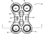
图45是图44的外科手术固定系统的俯视平面图;45 is a top plan view of the surgical fixation system of FIG. 44;
图46至47分别是图44的外科手术固定系统的底侧的立体图和平面图;以及46-47 are perspective and plan views, respectively, of the underside of the surgical fixation system of FIG. 44; and
图48是根据本发明的可选实施方式的利用接骨螺钉的本发明的外科手术固定系统的局部剖视图。48 is a partial cross-sectional view of the surgical fixation system of the present invention utilizing bone screws in accordance with an alternative embodiment of the present invention.
具体实施方式Detailed ways
以下描述本发明的示例性实施方式。为了清楚,本说明书中并未描述当前实施的所有特征。当然应理解,在研制任意该实际实施方式时,必须形成许多具体实施决定,以实现研制者的具体意图,例如遵从系统相关和商业相关的限制,这些限制在不同的实施中是不同的。而且,应理解,这样的研发可能复杂且耗时,然而是具有本公开优点的本领域的技术人员所采取的常规手段。本文所公开的外科手术固定板拥有授权专利保护的各种独创特征和部件,无论这些特征和部件是单独还是结合的。Exemplary embodiments of the present invention are described below. In the interest of clarity, not all features of the current implementation are described in this specification. It should of course be appreciated that in developing any such actual implementation, many implementation-specific decisions must be made to achieve the developer's specific intent, such as compliance with system-related and business-related constraints, which vary from implementation to implementation. Moreover, it will be appreciated that such development can be complex and time consuming, but is nevertheless a routine undertaking for those of skill in the art having the benefit of this disclosure. The surgical fixation plates disclosed herein possess various inventive features and components protected by issued patents, whether alone or in combination.
本发明通过提供这样的外科手术固定系统对现有技术进行改进,该外科手术固定系统包括外科手术固定板、多个螺钉和多个防退回元件,其中,所述防退回元件构造成且尺寸形成为接收在形成于外科手术固定板中的接骨螺钉孔内,以防止螺钉随着时间退回。如以下将描述的那样,防退回元件能够在将螺钉引入给定的整形外科目标之前容易地被引入接骨螺钉孔中。尽管特别适用于在前路颈椎固定中使用,但是本领域人员容易理解,本发明的外科手术固定系统可使用在任意数量的合适的整形外科手术固定方法和过程中,包括但不局限于前路、后路、侧路、前侧路、后侧路的腰脊柱固定、胸脊柱固定,以及任何非脊柱固定应用(例如骨折治疗)。另外,尽管仅通过实施例示出并描述成使用在4孔、两级板中,但是应理解,这样的防退回特征可使用在具有任意数量的接骨螺钉孔的板中,用于融合任意数量的椎级。The present invention improves upon the prior art by providing a surgical fixation system comprising a surgical fixation plate, a plurality of screws and a plurality of anti-retraction elements, wherein the anti-retraction elements are configured and dimensioned to To be received within the bone screw holes formed in the surgical fixation plate to prevent the screws from receding over time. As will be described below, the anti-retraction element can be easily introduced into the bone screw hole prior to introducing the screw into a given orthopedic target. Although particularly adapted for use in anterior cervical spine fixation, those skilled in the art will readily appreciate that the surgical fixation system of the present invention may be used in any number of suitable orthopedic fixation methods and procedures, including but not limited to anterior , posterior, lateral, anterior lateral, posterior lateral lumbar spine fixation, thoracic spine fixation, and any non-spinal fixation application (e.g. fracture treatment). Additionally, while shown and described by way of example only as being used in a 4-hole, two-stage plate, it should be understood that such an anti-retraction feature may be used in a plate with any number of bone screw holes for fusing any number of bone screw holes. Vertebral level.
图1示出根据本发明第一实施方式的外科手术固定系统10的实施例。该外科手术固定系统10包括外科手术固定板12、多个螺钉14以及多个防退回元件16。如以下将更详细说明的那样,本发明的外科手术固定系统10可用于提供沿整形外科的目标部位的临时或者永久的固定,目标部位包括但不局限于脊柱内的相邻椎级(例如,前路融合手术期间的颈椎、用于前路融合手术的腰椎等)。为此,板12首先被定位在目标部位上,使得螺钉14和防退回元件16之后可用于将板12联接到目标部位。根据本发明的一个方面,通过利用与形成在板12中的凹部协作的防退回元件16,防止螺钉14在放置之后从目标部位退回。Figure 1 shows an example of a
参照图2至5,外科手术固定板12包括第一表面18、第二表面20以及在第一表面18与第二表面20之间延伸的多个接骨螺钉孔22。每个接骨螺钉孔22具有第一开口24、第二开口26以及在其间延伸的内导槽28。凹部30设置在各接骨螺钉孔22内,并且绕第一开口24与第二开口26之间的内导槽28周向布置。该凹部的尺寸形成为接收防退回元件16的至少一部分。Referring to FIGS. 2-5 , the
板12可设置有多种不同周缘轮廓,包括但不局限于图中(图3中最佳可见)作为实施例所述的大体矩形周缘轮廓。板12还可以设置有观察孔32,或者不设置该观察孔,观察孔32形成在第一表面18与第二表面20之间,并且大体位于板12的中央部中。在将板12固定到患者之后,观察孔32用于察看脊柱目标部位或者使脊柱目标部位可见。应理解,观察孔32可设置成多种合适形状或者构造,而不脱离本发明的范围,因此不局限于通过图3中的实施例的方式所示的形状。The
除了观察孔32之外,板12可构造成包括缩进部36以及缩进部38,缩进部36在每对相邻孔22中间沿板12的侧面定位,缩进部38在每对相邻孔22中间定位在板12的两端上。缩进部36、38减少制造板12时使用的材料量,并且减小板12的总体轮廓,以增大已由观察孔32提供的观察能力。可在板12的任意一端设置至少一个插入孔40,用于接收插入器具的至少一部分。仅作为实施例,附图中所示的板12包括一对插入孔40,在板12的每端处设置一个插入孔40。插入孔40构造成接合插入装置(未示出)的至少一部分,因此可包括允许该接合所必须的任意合适的特征,包括但不局限于螺纹、隆起和凹部。In addition to viewing apertures 32,
图6示出根据本发明一个实施方式的防退回元件16的一个实施例。仅作为实施例,防退回元件16大体设置成大体圆形的(或者环形的)、连续倾斜的线圈环部件,该线圈环部件的尺寸形成为接收在板12的凹部30内。防退回元件16可限定成具有外圆周42、内圆周44以及由内圆周44限制的孔46。由于防退回元件16的倾斜线圈的性质,因此圆周42中的每个圆周独立可变。例如,当插入板12的凹部30中时(如图7所示),外圆周42可与凹部30的刚性圆周相对应。在接骨螺钉通过孔46插入后,内圆周44可伸展以使接骨螺钉的头部通过(以下进一步详细描述)。内圆周44的该伸展独立于外圆周42发生(例如与实心扣环的情况不同),因此可在外圆周42无任何伸展的情况下发生,通过凹部30的限制来防止外圆周42伸展。内圆周44因线圈的倾斜性质(图6中所示)而发生独立伸展,因为形成防退回元件16的各个线圈实际上会被螺钉头压靠在一起。换言之,由螺钉头施加的力不会使防退回元件16完全径向伸展,而是线圈的倾斜性质允许各个线圈抵靠相邻的线圈大体“变平”,因为线圈的内边缘(形成内圆周)将趋于沿一个方向移动,因此使内圆周伸展,同时线圈的外边缘(形成外圆周)将保持静止,致使外圆周无变化。FIG. 6 shows an example of an
仅作为实施例,防退回元件16的单独环和外圆周42和内圆周44可具有多种合适尺寸。防退回元件16可由任意合适的生物相容性材料形成,包括但不局限于金属。根据一优选实施方式,在使用时,防退回元件16在外科手术过程期间的插入之前设置在板12的凹部30内。然而应理解,防退回元件16可有选择地定位在形成于螺钉头内的对应槽内,而不脱离本发明的范围。By way of example only, the separate rings and outer and
图8示出根据本发明一个实施方式的固定角接骨螺钉14的实施例。各螺钉14包括由颈部区域56分开的锚固区域52和头部区域54。锚固区域52包括大体细长的轴58,轴58具有至少一个大体螺旋形螺纹60。轴58具有比接骨螺钉孔22小的直径,颈部区域56和螺纹60的直径与孔22的直径基本相似,头部区域54的外径比孔22的外径大。附加地,颈部区域56形状上为大体圆柱形,其与孔22结合的相对尺寸防止固定角螺钉14在插入孔22时移动。由于接骨螺钉14通过板12前进,因此,螺纹60与骨接合,以将板12固定到椎骨。头部区域54可配备有用于与引入装置(例如螺丝起子)接合的多种机构,包括但不局限于六角头凹部62。而且,尽管示出为单个螺纹60,但应理解,细长轴58可配备有多个螺纹60,而不脱离本发明的范围。Figure 8 shows an example of a fixed
注意,头部区域54包括唇部64,唇部64的直径小于孔22的第一开口24,而大于孔22的第二开口26。因此,唇部64能够穿过第一开口24,而不能穿过第二开口26。唇部64包括大体从头部区域54垂直延伸的大体平坦的突出部66以及将大体平坦突出部66与颈部区域56连接的大体角形部68。如图16至17所示,在将螺钉14插入孔22中后,如上所述,大体角形部68将向防退回元件16施加力,以允许突出部66从其通过。在螺钉14的插入完成后,突出部66完全通过防退回元件16,并与防退回元件16相互作用,使得突出部66接合内圆周44的至少一部分。防止大体角形部68穿过第二开口26,并且防止突出部66穿过防退回元件16(在缺少例如利用合适工具在修复过程中提供的较大力的情况下)。因此,防退回元件16与突出部66相互作用,以为固定系统10提供防退回特征。Note that the
图9示出根据本发明一个实施方式的多轴接骨螺钉70的一个实施例。各螺钉70包括由颈部区域76分开的锚固区域72和头部区域74。对应特征与固定角螺钉14的特征相似,从而不必重复。然而明显差异在于颈部区域76为大体弯曲的或者呈锥形,以允许螺钉在插入椎骨后在患者的正常活动期间因椎骨的自然移位而移动。与上述固定角螺钉14一样,多轴接骨螺钉70设置有:唇部78,该唇部具有从头部区域74大体垂直延伸的大体平坦的突出部80;以及大体角形部82,该角形部82连接突出部80与颈部76。因此,多轴接骨螺钉70设置有与固定角螺钉14相同的防退回特征。类似地,头部区域74可配备有用于与引入装置(例如螺丝起子)接合的多种机构,包括但不局限于六角头凹部75。Figure 9 shows an example of a
图10至11示出根据本发明的可选实施方式的多轴接骨螺钉90的一个实施例。螺钉90包括锚固部92、头部94以及位于其间的颈部区域96。螺钉90与螺钉70的不同之处在于唇部98不是螺钉90的一体部,因此能够绕头部94有限地移动。因此,当以一定角度插入板12中时,唇部98可略移动成与防退回元件16平齐地接合,并且使接骨螺钉90可能更容易插入。一旦插入,则螺钉90具有如上所述相同的防退回特征。头部区域94可配备有用于与引入装置(例如螺丝起子)接合的任意数量的机构,包括但不局限于六角头凹部95。而且,头部区域94还可包括内螺纹区域97,用于在接骨螺钉90的修复或者重新定位的情况下与移除装置接合。该特征可存在于本文所述的接骨螺钉的任意实施方式上,而不脱离本发明的范围。10-11 illustrate one example of a
图12至15示出根据本发明的再一可选实施方式的多轴接骨螺钉500的另一个实施例。螺钉500包括锚固部502、头部504以及位于其间的颈部区域506。螺钉500与螺钉90的相似之处在于唇部508不是螺钉500的一体部,因此能够绕头部504有限地移动。因此,当以一定角度插入板12中时,唇部508可略移动成与防退回元件16平齐地接合,并且使接骨螺钉500可能更容易插入。一旦插入,则螺钉500具有如上所述相同的防退回特征。头部区域504可配备有用于与引入装置(例如螺丝起子)接合的多种机构,包括但不局限于六角头凹部518。而且,头部区域504还可包括内螺纹区域520,用于在接骨螺钉90修复或者重新定位的情况下与移除装置接合。12 to 15 illustrate another example of a
接骨螺钉500与螺钉90的不同之处在于,颈部区域506向外形成角度,并且终止在头部504的基部处的大体平坦支架510中。支架510用于保持唇部508,并且防止其沿锚固部502向远端移动。唇部508的形状大体为圆形,并且包括顶面512、内圆周面514以及侧圆周面516。顶面512大体平坦,并且尺寸形成为与如上所述的防退回元件16接合。内圆周面514的形状为半球形,以与头部504的基部的半球形状匹配。侧圆周面516以大体弯曲的方式从顶面512的边缘延伸,直到其与内圆周面514接合时为止。头部区域还包括
为了组装接骨螺钉500,唇部508沿锚固部502螺纹前进至颈部506的基部。唇部508的底端的圆周小于支架510的圆周。然而,当唇部越过支架510前进时,唇部508的底端的圆周略微伸展,以允许卡合组装接骨螺钉500。To assemble
图18至19示出根据本发明的第二主要方面的外科手术固定系统110。为了简化说明,外科手术固定系统110的与外科手术固定系统10的元件基本相同的元件标以相同的附图标记。外科手术固定系统110示出适用于前路腰椎固定的本发明的特定实施方式的实施例。外科手术固定系统110包括外科手术固定板112、多个螺钉114以及多个防退回元件16。Figures 18 to 19 show a
图20至25更详细地示出板12。外科手术固定板112包括第一表面118、第二表面120以及在第一表面180和第二表面120之间延伸的多个接骨螺钉孔122。每个接骨螺钉孔122具有第一开口124、第二开口126以及在第一开口124与第二开口126之间延伸的内导槽128。凹部130设置在各接骨螺钉孔122内,并且绕第一开口124与第二开口126之间的内导槽128周向布置。该凹部的尺寸形成为接收防退回元件16的至少一部分。Figures 20 to 25 show the
板112与上述的板12的不同之处在于其包括中央凹进区域132和骶骨唇部件136,中央凹进区域132具有多个位于板的顶侧上的孔134,骶骨唇部件136设置在板112的第二表面120(即,脊椎接触侧)上。以下更加详细地说明螺钉114的具体特征。防退回元件16与上述的板12的对应特征基本相同,因此这里将不再重复。
凹进区域132大体为细长,并且布置在板112的顶面内的大体中央位置中。例如图20至23中所示的板112包括凹进区域132,凹进区域132具有一对布置在该细长凹进区域132的任意一端处的孔134。然而,应理解,如果需要,可设置任意数量的孔134。孔134(以及凹进区域132)的尺寸形成为与在将板112植入外科手术目标部位中使用的各种仪器138(图27、28)接合,包括但不局限于板插入件、钻导向件、螺钉插入件等。而且,板112可设置有任选的辅助防退回装置(未示出),该辅助防退回装置的尺寸形成为在孔134处接合板112,并且在相邻的螺钉孔122的至少一个上至少部分延伸,以防止螺钉和/或防退回元件16从螺钉孔排出。任选的辅助防退回装置主要用于增大外科手术固定系统110的防退回能力,并且尺寸可形成为与螺钉114和/或防退回元件16的至少一部分接合。The recessed
板112还设置有骶骨唇部件136,该骶骨唇部件136设置在板112的第二表面120上(即脊椎接触侧)。骶骨唇部件136大体布置成与最后部的一对螺钉孔相邻,并且尺寸形成为抵靠骶骨安置,例如如图28中所示。该唇部件118允许在将板112固定在前路腰椎区域时更稳定。The
图29至32示出外科手术固定板212的一个实施例,外科手术固定板212的尺寸形成为用于多级前路腰椎固定,例如根据本发明的可选实施方式的L4至S1固定。板212的特征与上述的板112的特征基本类似,包括第一表面218、第二表面220以及在第一表面218与第二表面220之间延伸的多个接骨螺钉孔222a至222c。与板112一样,板212包括:一对凹进区域232,凹进区域232均具有多个位于板的顶侧的孔234;以及设置在板212的第二表面220上(即脊椎接触侧)的骶骨唇部件236。这些特征与板112的对应特征基本相似(如果不相同的话),因此在这里将不再重复所述细节。29 to 32 illustrate one embodiment of a
板212与板112的不同之处在于其尺寸形成为用于多级前路腰椎固定,例如L4至S1的固定。因此,该板包括至少三个固定区域240、242、244。例如,第一固定区域240布置在板的一端处,并且尺寸形成为放置在第一椎体(例如S1椎骨)上。第一固定区域240包括与上述的接骨螺钉孔22相似的第一对接骨螺钉孔222a。第一固定区域240还包括第二表面220上的骶骨唇部件236。
第二固定区域242定位在板212内,并且尺寸形成为放置在第二椎体(例如L5椎骨)上。第二固定区域242包括一对与上述接骨螺钉孔22相似的接骨螺钉孔222b。第二固定区域242通过板212的第一主体部246与第一固定区域240分离。The
第三固定区域244定位在板212的与第一固定区域240相反的一端,并且尺寸形成为放置在第三椎体(例如L4椎骨)上。第三固定区域244包括一对与上述的接骨螺钉孔22相似的接骨螺钉孔222c。第三固定区域通过板212的第二主体部248与第二固定区域分离。第二主体部248的尺寸比第一主体部246的尺寸大,以说明脊柱在具体区域(L4至S1)中的解剖结构。然而,板212的具体尺寸(包括第一和第二主体部246、248的相对尺寸和长度)可基于植入的具体椎级而不同。另外,板212可不设置骶骨唇部件236,而不脱离本发明的范围。尽管针对放置在脊柱(例如L4至S1固定)内的具体实施例进行描述,但是,板212可用于脊柱的其它区域中,并且可用于整个人体的其它地方。The
图33至44示出根据本发明的可选实施方式的板312的实施例,板312的尺寸形成为用于前路腰椎固定。板312的特征与上述的板112的特征基本相似,包括第一表面318、第二表面320以及在第一表面318与第二表面320之间延伸的多个接骨螺钉孔322。与板112一样,板312包括中央凹进区域332,中央凹进区域332具有多个位于板的顶侧的孔334。这些特征与板112的对应特征基本相似(如果不相同的话),因此在这里不再重复所述细节。板312与板112的不同之处在于其不包括板312的第二表面320(即椎骨接触侧)上的骶骨唇部件。仅作为实施例,板312可用于涉及脊柱的腰椎区域但不包括骶骨的固定外科手术中。板312还可用于脊柱的其它区域中和人体内的其它地方,而不脱离本发明的范围。33 to 44 illustrate an example of a
图35至37示出与上述的各种骨板的实施方式一起使用的根据本发明的一个实施方式的接骨螺钉114的实施例。接骨螺钉114包括头部150、颈部区域152、细长轴154、帽156以及垫圈158。轴154包括用于拧到骨节(例如椎体)中的螺纹160。35-37 illustrate an example of a
参照图38至39,头部150包括第一突起162、圆周凹部164、第二突起166以及布置在头部150的顶部上的工具接合凹部168。圆周凹部164设置在第一突起162和第二突起166之间,并且尺寸形成为接收垫圈158。第一突起162与第二突起166之间的距离(即凹部164的高度尺寸)大于垫圈158的高度尺寸,以允许使垫圈在凹部164内受控地移动。工具接合凹部168可成形为对应于螺丝起子(未示出)所必需的任意形状。颈部区域152在第一突起162下方延伸,并且可基于所需要的(例如固定角或者可变角)螺钉的特定类型而改变大小和宽度。固定角螺钉具有其宽度比可变角螺钉大的颈部区域152,以确保固定角螺钉相对于板的接骨螺钉孔不移动。Referring to FIGS. 38 to 39 , the
图40至41更详细地示出帽156的实施例。帽156大体为圆形,并且包括内支架170,内支架170的尺寸形成为与头部150的第二突起166相互作用。帽156用于增大头部150的顶部在接骨螺钉孔内的宽度,并且还用于帮助将垫圈158保持在圆周凹部164内。40-41 illustrate an embodiment of the
图42至43更详细地示出垫圈158的实施例。垫圈158的形状大体为圆形,并且包括顶面172、底面174、内圆周面176以及侧圆周面178。顶面172和底面174大体平坦,并且尺寸形成为分别与第一突起162和第二突起166接合。顶面172的尺寸还形成为与如上所述的防退回元件16接合。顶面172和底面174均具有由各自外边缘的圆周限定的最大圆周。在所示的实施方式中,顶面172的最大圆周大于底面174的最大圆周。内圆周面176的尺寸形成为与头部150的圆周凹部164的内部相互作用。侧圆周面178以大体角形的方式在顶面172与底面174之间延伸。42-43 illustrate an embodiment of the
当前实施方式的垫圈158的作用类似的如上涉及接骨螺钉14所述的唇部件64。因此,垫圈158能够穿过板112的第一开口124,但不能穿过第二开口126。在螺钉114被插入孔122中之后,侧圆周面178如上所述将向防退回元件16施加力,以允许顶面172从其通过。螺钉114的插入完成之后,顶面172完全通过防退回元件16,并且与防退回元件16相互作用,使得顶面172与凹部130的至少一部分接合。防止大体侧向的圆周面178穿过第二开口126,防止顶面172穿过防退回元件16(在缺少例如利用合适工具在修复过程中提供的较大力的情况下)。因此,防退回元件16与顶面172相互作用,为外科手术固定系统10提供防退回特征。The
图44至47示出根据本发明第三实施方式的外科手术固定系统410的实施例。为了简化说明,外科手术固定系统410的与外科手术固定系统10的元件基本相同的元件被标以相同的附图标记。外科手术固定系统410包括外科手术固定板412、多个螺钉(未画出)以及多个防退回元件16。板412与上述板12的不同之处在于其具有较窄的尺寸大小,以允许使每个椎级仅一个固定螺钉,并且包括下述若干附加特征。尽管示画出,但该螺钉与上述的螺钉14基本相同。螺钉14与防退回元件16的具体特征以及它们与板412的相互作用与板12的对应特征基本相同,因此这里不再重复。44 to 47 show an example of a
如以下更详细地说明,本发明的外科手术固定系统410可用于提供沿整形外科目标部位的临时或者永久固定,目标部位包括但不局限于脊柱内的相邻椎级(例如,前路融合手术期间的颈椎、用于前路融合外科手术的腰椎等)。为此,板412首先被定位在目标部位上,使得螺钉14和防退回元件16之后可用于将板412联接到目标部位。根据本发明的一个方面,通过利用与形成在板412中的凹部协作的防退回元件16防止螺钉14在放置之后从目标部位退回。As described in more detail below, the
参照图44至47,外科手术固定板412包括第一表面418、第二表面420以及在第一表面418与第二表面420之间延伸的多个接骨螺钉孔422。接骨螺钉孔422呈现与如上所述的接骨螺钉孔22相同的特征。板412在的现场放置使得各接骨螺钉孔422与不同的椎体对准。这样,图44至47中所示的板412构造成用于“两级”固定,因为板412横跨其间具有一个锥体的两个椎间空间。然而,板412可构造成使其应用于单级固定(即,相邻椎骨之间的一个椎间空间)或者多级固定,而不脱离本发明的范围。Referring to FIGS. 44-47 , the
板412可设置有多种不同周缘轮廓,包括但不局限于图中(并且在图45中最佳可见)作为实施例阐述的具有纵轴线A1的大体矩形周缘轮廓。板412具有位于20mm至50mm之间的长度尺寸、位于10mm至12mm之间的宽度尺寸以及位于1mm至2.5mm之间的厚度尺寸。板412包括形成于第一表面418与第二表面420之间和相邻的接骨螺钉孔422之间的观察孔432。在板412固定到患者后,观察孔432用于察看椎骨目标部位或者使椎骨目标部位可见。应理解,观察孔432可设置成多种合适形状或者构造,而不脱离本发明的范围,因此不局限于由图45中的实施例所示的形状。
除了观察孔432之外,板412可构造成包括缩进部436,缩进部436在各对相邻孔422中间沿板412的侧面定位。缩进部436减少了在制造板412时使用的材料量,并且减小了板412的总体轮廓,以增大已由观察孔432提供的观察能力。板412的任意一端或者两端可包括倾斜面438,倾斜面438产生具有近似1mm的厚度的前边缘440。该1mm的前/后边缘进一步减小了板412在边缘处的轮廓,并且使得与附近的解剖结构的干涉最小。In addition to
参照图46,第二表面420构造成与椎体接合。这样,第二表面420包括环绕接骨螺钉孔422的粗糙(textured)区域450、452、454。各粗糙区域450、452、454包括多个构造成限制或者防止板相对于相邻椎体运动的防移动构件。第一粗糙区域450位于朝板412一端定位的第一接骨螺钉孔422的周围,并且包括多个径向布置在孔422周围的防移动构件456。仅作为实施例示出的防移动构件456为具有大体三角形截面的细长隆起(长度可变)。然而,也可以是其它形状。防移动构件456的形状和构造用于允许板412抵靠椎体刚性放置,并且防止板相对于椎体运动,从而保持所期望的对准。Referring to Figure 46, the second surface 420 is configured to engage a vertebral body. As such, the second surface 420 includes textured regions 450 , 452 , 454 surrounding the
第二粗糙区域452位于第二接骨螺钉孔422的周围,例如图46至47中所示的实施例中的中间接骨螺钉孔422的周围。第二粗糙区域452包括多个防移动构件458,防移动构件458线性布置并且平行于板412的纵轴线A1(图45)。仅作为实施例示出的防移动构件458为具有大体三角形截面的细长隆起(长度可变)。然而,也可以是其它形状。防移动构件458的形状和构造用于允许板412相对于相邻的椎骨沿平行于板412的纵轴线A1的方向的受限运动,但是防止板沿任意其它方向运动。该特征很重要,因为其允许相邻椎骨的压缩而不影响板412的对准。The second roughened area 452 is located around the second
第三粗糙区域454位于第三接骨螺钉孔422的周围,例如位于板412的另一端处的孔422的周围。在该实施例中,第三粗糙区域454包括具有与粗糙区域452的防移动构件458相同的形状和布置的防移动构件460。尽管通过实施例示出具有径向配置的一个粗糙区域450和具有线性配置的两个粗糙区域452、454,以允许压缩,但也可以基于患者的具体需要任意地结合径向和线性配置。然而通常,板412具有至少一个具有径向配置的粗糙区域和至少一个具有线性配置的粗糙区域。The third roughened area 454 is located around the third
在本文所述的所有实施方式中,防退回元件用于阻止接骨螺钉的退回趋势。然而,防退回元件不将接骨螺钉锁定到板。这是因为可通过施加足够大小的力来拉动唇部件(或者垫圈)通过防退回部件而使接骨螺钉从接骨螺钉孔移除。由于上述的倾斜线圈环的性质和唇部件(或垫圈)的尺寸,移除插入的接骨螺钉所需要的力比插入接骨螺钉所需要的力大。然而,接骨螺钉可以在单步骤过程中插入和/或移除,而不需要防退回元件的分离操作。In all of the embodiments described herein, the anti-retraction element serves to counteract the tendency of the bone screw to recede. However, the anti-retraction element does not lock the bone screw to the plate. This is because the bone screw can be removed from the bone screw hole by applying a sufficient amount of force to pull the lip member (or washer) past the anti-retraction member. Due to the nature of the angled coil loop and the size of the lip (or washer) described above, the force required to remove an inserted bone screw is greater than the force required to insert a bone screw. However, bone screws can be inserted and/or removed in a single-step process without the need for disengagement of the anti-retraction element.
尽管本发明允许各种变更和可选形式,但是已通过图中的实施例示出其具体实施方式,并且在本文中进行详细描述。例如,图48示出根据本发明的又一可选实施方式的接骨螺钉14的一个实施例,其中,螺钉14包括近端唇部件100。然而应理解,本文描述的具体实施方式不旨在将本发明限定于所公开的具体形式,而相反,本发明旨在覆盖落入如本文所述的本发明的精神和范围内的所有修改例、等同例以及可选例。While the invention is susceptible to various modifications and alternative forms, specific embodiments thereof have been shown by way of example in the drawings and described in detail herein. For example, FIG. 48 shows an example of a
Claims (28)
Applications Claiming Priority (5)
| Application Number | Priority Date | Filing Date | Title |
|---|---|---|---|
| US96558907P | 2007-08-20 | 2007-08-20 | |
| US60/965,589 | 2007-08-20 | ||
| US5779308P | 2008-05-30 | 2008-05-30 | |
| US61/057,793 | 2008-05-30 | ||
| PCT/US2008/009964 WO2009025841A1 (en) | 2007-08-20 | 2008-08-20 | Surgical fixation system and related methods |
Publications (1)
| Publication Number | Publication Date |
|---|---|
| CN101835437A true CN101835437A (en) | 2010-09-15 |
Family
ID=40378475
Family Applications (1)
| Application Number | Title | Priority Date | Filing Date |
|---|---|---|---|
| CN200880112434A Pending CN101835437A (en) | 2007-08-20 | 2008-08-20 | Surgical fixation system and related methods |
Country Status (7)
| Country | Link |
|---|---|
| US (2) | US20110319943A1 (en) |
| EP (1) | EP2190366A4 (en) |
| JP (1) | JP2010536478A (en) |
| KR (1) | KR20100074151A (en) |
| CN (1) | CN101835437A (en) |
| AU (1) | AU2008289436A1 (en) |
| WO (1) | WO2009025841A1 (en) |
Cited By (2)
| Publication number | Priority date | Publication date | Assignee | Title |
|---|---|---|---|---|
| CN113456205A (en) * | 2021-06-29 | 2021-10-01 | 北京市春立正达医疗器械股份有限公司 | Disc type wrist joint fusion bone plate and using method thereof |
| CN113813033A (en) * | 2021-09-24 | 2021-12-21 | 浙江省立同德医院 | Angle-adjustable self-locking type lumbosacral anterior channel vertebral arch fixing nail plate fixing method and system |
Families Citing this family (33)
| Publication number | Priority date | Publication date | Assignee | Title |
|---|---|---|---|---|
| WO2008070863A2 (en) | 2006-12-07 | 2008-06-12 | Interventional Spine, Inc. | Intervertebral implant |
| US9039768B2 (en) | 2006-12-22 | 2015-05-26 | Medos International Sarl | Composite vertebral spacers and instrument |
| US9060813B1 (en) | 2008-02-29 | 2015-06-23 | Nuvasive, Inc. | Surgical fixation system and related methods |
| US20090248092A1 (en) | 2008-03-26 | 2009-10-01 | Jonathan Bellas | Posterior Intervertebral Disc Inserter and Expansion Techniques |
| US9526620B2 (en) | 2009-03-30 | 2016-12-27 | DePuy Synthes Products, Inc. | Zero profile spinal fusion cage |
| US8287597B1 (en) | 2009-04-16 | 2012-10-16 | Nuvasive, Inc. | Method and apparatus for performing spine surgery |
| US8876869B1 (en) * | 2009-06-19 | 2014-11-04 | Nuvasive, Inc. | Polyaxial bone screw assembly |
| US9393129B2 (en) | 2009-12-10 | 2016-07-19 | DePuy Synthes Products, Inc. | Bellows-like expandable interbody fusion cage |
| US20120078372A1 (en) | 2010-09-23 | 2012-03-29 | Thomas Gamache | Novel implant inserter having a laterally-extending dovetail engagement feature |
| US11529241B2 (en) | 2010-09-23 | 2022-12-20 | DePuy Synthes Products, Inc. | Fusion cage with in-line single piece fixation |
| US20120078373A1 (en) | 2010-09-23 | 2012-03-29 | Thomas Gamache | Stand alone intervertebral fusion device |
| US8940030B1 (en) | 2011-01-28 | 2015-01-27 | Nuvasive, Inc. | Spinal fixation system and related methods |
| US9387013B1 (en) | 2011-03-01 | 2016-07-12 | Nuvasive, Inc. | Posterior cervical fixation system |
| US9248028B2 (en) | 2011-09-16 | 2016-02-02 | DePuy Synthes Products, Inc. | Removable, bone-securing cover plate for intervertebral fusion cage |
| US11123117B1 (en) | 2011-11-01 | 2021-09-21 | Nuvasive, Inc. | Surgical fixation system and related methods |
| US8852278B2 (en) | 2011-12-22 | 2014-10-07 | DePuy Synthes Products, LLC | Lateral cage with integrated plate |
| US9271836B2 (en) | 2012-03-06 | 2016-03-01 | DePuy Synthes Products, Inc. | Nubbed plate |
| US20130345813A1 (en) | 2012-06-22 | 2013-12-26 | Sheryl Frank | Dual Anchor Lateral Vertebral Body Fixation Plates |
| US10182921B2 (en) | 2012-11-09 | 2019-01-22 | DePuy Synthes Products, Inc. | Interbody device with opening to allow packing graft and other biologics |
| US9717601B2 (en) | 2013-02-28 | 2017-08-01 | DePuy Synthes Products, Inc. | Expandable intervertebral implant, system, kit and method |
| US9510880B2 (en) | 2013-08-13 | 2016-12-06 | Zimmer, Inc. | Polyaxial locking mechanism |
| KR200479198Y1 (en) * | 2013-11-12 | 2015-12-31 | 유상진 | Fixing Plate Of Mandible |
| US10188433B2 (en) * | 2015-07-08 | 2019-01-29 | Benito J. GARRIDO | Anterior cervical plates for spinal surgery employing anchor backout prevention devices, and related systems and methods |
| EP3178423B1 (en) * | 2015-12-10 | 2018-02-21 | Stryker European Holdings I, LLC | Bone plate with polyaxial locking mechanism |
| US9918750B2 (en) * | 2016-08-04 | 2018-03-20 | Osseus Fusion Systems, Llc | Method, system, and apparatus for temporary anterior cervical plate fixation |
| US10940016B2 (en) | 2017-07-05 | 2021-03-09 | Medos International Sarl | Expandable intervertebral fusion cage |
| US11033310B2 (en) * | 2017-08-15 | 2021-06-15 | Gomboc, LLC | Magnetic screw and plate apparatus |
| US11039865B2 (en) | 2018-03-02 | 2021-06-22 | Stryker European Operations Limited | Bone plates and associated screws |
| USD877906S1 (en) * | 2018-12-28 | 2020-03-10 | Curiteva, Inc. | Cervical bone plate device |
| USD877905S1 (en) * | 2018-12-28 | 2020-03-10 | Curiteva, Inc. | Cervical bone plate device |
| CN110123432A (en) * | 2019-05-15 | 2019-08-16 | 山东新华联合骨科器材股份有限公司 | A kind of cervical bone plate system |
| USD971411S1 (en) * | 2020-08-27 | 2022-11-29 | L&K Biomed Co., Ltd. | Spinal plate |
| US11752009B2 (en) | 2021-04-06 | 2023-09-12 | Medos International Sarl | Expandable intervertebral fusion cage |
Family Cites Families (79)
| Publication number | Priority date | Publication date | Assignee | Title |
|---|---|---|---|---|
| JPS5232152A (en) | 1975-09-05 | 1977-03-11 | Nissan Motor Co Ltd | Seal of heat exchanger of rotary and accumulating type |
| US4655462A (en) | 1985-01-07 | 1987-04-07 | Peter J. Balsells | Canted coiled spring and seal |
| DE8513288U1 (en) | 1985-05-06 | 1986-09-04 | Wolter, Dietmar, Prof. Dr., 2000 Hamburg | Osteosynthesis plate |
| ES2124288T3 (en) | 1992-11-25 | 1999-02-01 | Codman & Shurtleff | PLATE SYSTEM FOR OSTEOSYNTHESIS. |
| US5364399A (en) | 1993-02-05 | 1994-11-15 | Danek Medical, Inc. | Anterior cervical plating system |
| US5549607A (en) * | 1993-02-19 | 1996-08-27 | Alphatec Manufacturing, Inc, | Apparatus for spinal fixation system |
| US5675666A (en) | 1995-03-02 | 1997-10-07 | Sony Corportion | Image data compression method and apparatus with pre-processing to compensate for the blocky effect |
| US5520690A (en) | 1995-04-13 | 1996-05-28 | Errico; Joseph P. | Anterior spinal polyaxial locking screw plate assembly |
| US5716399A (en) * | 1995-10-06 | 1998-02-10 | Cardiomend Llc | Methods of heart valve repair |
| FR2748387B1 (en) | 1996-05-13 | 1998-10-30 | Stryker France Sa | BONE FIXATION DEVICE, IN PARTICULAR TO THE SACRUM, IN OSTEOSYNTHESIS OF THE SPINE |
| US5931838A (en) | 1997-01-28 | 1999-08-03 | Vito; Raymond P. | Fixation assembly for orthopedic applications |
| DE69839011T2 (en) | 1997-02-11 | 2009-01-08 | Warsaw Orthopedic, Inc., Warsaw | DEVICE FOR ATTACHING SKELETAL PANELS |
| ES2268267T3 (en) | 1997-02-11 | 2007-03-16 | Warsaw Orthopedic, Inc. | PREVIOUS CERVICAL PLATE FOR UNIQUE TYPE LOCK DEVICE. |
| USD449692S1 (en) * | 1998-02-11 | 2001-10-23 | Gary K. Michelson | Anterior cervical plate |
| ZA983955B (en) | 1997-05-15 | 2001-08-13 | Sdgi Holdings Inc | Anterior cervical plating system. |
| US6235034B1 (en) | 1997-10-24 | 2001-05-22 | Robert S. Bray | Bone plate and bone screw guide mechanism |
| US5951558A (en) | 1998-04-22 | 1999-09-14 | Fiz; Daniel | Bone fixation device |
| US6533786B1 (en) | 1999-10-13 | 2003-03-18 | Sdgi Holdings, Inc. | Anterior cervical plating system |
| FR2778088B1 (en) | 1998-04-30 | 2000-09-08 | Materiel Orthopedique En Abreg | ANTERIOR IMPLANT, PARTICULARLY FOR THE CERVICAL RACHIS |
| US6241731B1 (en) | 1998-08-11 | 2001-06-05 | Daniel Fiz | Plate and screw assembly for fixing bones |
| FR2784570B1 (en) | 1998-10-19 | 2001-02-16 | Scient X | INTERVERTEBRAL CONNECTION DEVICE HAVING ANTI-EXTRACTION MEANS FOR ANCHORAGE SCREWS |
| US6261291B1 (en) | 1999-07-08 | 2001-07-17 | David J. Talaber | Orthopedic implant assembly |
| US6224602B1 (en) | 1999-10-11 | 2001-05-01 | Interpore Cross International | Bone stabilization plate with a secured-locking mechanism for cervical fixation |
| US6692503B2 (en) | 1999-10-13 | 2004-02-17 | Sdgi Holdings, Inc | System and method for securing a plate to the spinal column |
| US6328738B1 (en) | 1999-11-24 | 2001-12-11 | Loubert Suddaby | Anterior cervical fusion compression plate and screw guide |
| US6331179B1 (en) | 2000-01-06 | 2001-12-18 | Spinal Concepts, Inc. | System and method for stabilizing the human spine with a bone plate |
| US6235033B1 (en) | 2000-04-19 | 2001-05-22 | Synthes (Usa) | Bone fixation assembly |
| JP2002000611A (en) | 2000-05-12 | 2002-01-08 | Sulzer Orthopedics Ltd | Bone screw to be joined with the bone plate |
| FR2810532B1 (en) | 2000-06-26 | 2003-05-30 | Stryker Spine Sa | BONE IMPLANT WITH ANNULAR LOCKING MEANS |
| AU757023B2 (en) * | 2000-06-26 | 2003-01-30 | Stryker European Holdings I, Llc | Bone screw retaining system |
| US6730127B2 (en) | 2000-07-10 | 2004-05-04 | Gary K. Michelson | Flanged interbody spinal fusion implants |
| US6485491B1 (en) | 2000-09-15 | 2002-11-26 | Sdgi Holdings, Inc. | Posterior fixation system |
| US6503250B2 (en) | 2000-11-28 | 2003-01-07 | Kamaljit S. Paul | Bone support assembly |
| US6413259B1 (en) | 2000-12-14 | 2002-07-02 | Blackstone Medical, Inc | Bone plate assembly including a screw retaining member |
| TW499953U (en) | 2000-12-19 | 2002-08-21 | Jr-Yi Lin | Spine fastening reposition device |
| US6641583B2 (en) * | 2001-03-29 | 2003-11-04 | Endius Incorporated | Apparatus for retaining bone portions in a desired spatial relationship |
| WO2002080789A1 (en) | 2001-04-05 | 2002-10-17 | Osteotech, Inc. | Bone fixation system and method |
| FR2823096B1 (en) | 2001-04-06 | 2004-03-19 | Materiel Orthopedique En Abreg | PLATE FOR LTE AND LTE VERTEBRATE OSTEOSYNTHESIS DEVICE, OSTEOSYNTHESIS DEVICE INCLUDING SUCH A PLATE, AND INSTRUMENT FOR LAYING SUCH A PLATE |
| US6599290B2 (en) | 2001-04-17 | 2003-07-29 | Ebi, L.P. | Anterior cervical plating system and associated method |
| US6361537B1 (en) * | 2001-05-18 | 2002-03-26 | Cinci M. Anderson | Surgical plate with pawl and process for repair of a broken bone |
| DE10152094C2 (en) * | 2001-10-23 | 2003-11-27 | Biedermann Motech Gmbh | Bone fixation device |
| US7766947B2 (en) | 2001-10-31 | 2010-08-03 | Ortho Development Corporation | Cervical plate for stabilizing the human spine |
| WO2003046392A2 (en) * | 2001-11-21 | 2003-06-05 | Bal Seal Engineering Co., Inc. | Connector with radial spring |
| US6755833B1 (en) | 2001-12-14 | 2004-06-29 | Kamaljit S. Paul | Bone support assembly |
| US7070599B2 (en) | 2002-07-24 | 2006-07-04 | Paul Kamaljit S | Bone support assembly |
| US7303564B2 (en) * | 2002-02-01 | 2007-12-04 | Spinal Concepts, Inc. | Spinal plate extender system and method |
| US20050096657A1 (en) | 2002-02-26 | 2005-05-05 | Alex Autericque | Osteosynthesis or arthrodesis material comprising a bony plate |
| US6695846B2 (en) | 2002-03-12 | 2004-02-24 | Spinal Innovations, Llc | Bone plate and screw retaining mechanism |
| US20030187443A1 (en) * | 2002-03-27 | 2003-10-02 | Carl Lauryssen | Anterior bone plate system and method of use |
| US7004944B2 (en) | 2002-07-16 | 2006-02-28 | Sdgi Holdings, Inc. | Bone plate fastener retaining mechanisms and methods |
| US7060067B2 (en) | 2002-08-16 | 2006-06-13 | Sdgi Holdings, Inc. | Systems, instrumentation and techniques for retaining fasteners relative to a bone plate |
| US7220263B2 (en) * | 2002-10-04 | 2007-05-22 | Seaspine, Inc. | Cervical plate/screw system for immobilizing vertebral bodies |
| US7524325B2 (en) | 2002-11-04 | 2009-04-28 | Farid Bruce Khalili | Fastener retention system |
| US7914561B2 (en) | 2002-12-31 | 2011-03-29 | Depuy Spine, Inc. | Resilient bone plate and screw system allowing bi-directional assembly |
| US7048739B2 (en) * | 2002-12-31 | 2006-05-23 | Depuy Spine, Inc. | Bone plate and resilient screw system allowing bi-directional assembly |
| US7175624B2 (en) * | 2002-12-31 | 2007-02-13 | Depuy Spine, Inc. | Bone plate and screw system allowing bi-directional assembly |
| US7481829B2 (en) | 2003-04-21 | 2009-01-27 | Atlas Spine, Inc. | Bone fixation plate |
| US6945973B2 (en) | 2003-05-01 | 2005-09-20 | Nuvasive, Inc. | Slidable bone plate system |
| US7087057B2 (en) * | 2003-06-27 | 2006-08-08 | Depuy Acromed, Inc. | Polyaxial bone screw |
| US7625375B2 (en) | 2003-08-06 | 2009-12-01 | Warsaw Orthopedic, Inc. | Systems and techniques for stabilizing the spine and placing stabilization systems |
| US7909860B2 (en) * | 2003-09-03 | 2011-03-22 | Synthes Usa, Llc | Bone plate with captive clips |
| US7857839B2 (en) | 2003-09-03 | 2010-12-28 | Synthes Usa, Llc | Bone plate with captive clips |
| US7740649B2 (en) * | 2004-02-26 | 2010-06-22 | Pioneer Surgical Technology, Inc. | Bone plate system and methods |
| US7311712B2 (en) * | 2004-02-26 | 2007-12-25 | Aesculap Implant Systems, Inc. | Polyaxial locking screw plate assembly |
| US7892257B2 (en) * | 2004-02-27 | 2011-02-22 | Custom Spine, Inc. | Spring loaded, load sharing polyaxial pedicle screw assembly and method |
| US7274964B2 (en) * | 2004-04-16 | 2007-09-25 | Bal Seal Engineering Co., Inc. | Use of an axial canted coil spring as an electrical contact to minimize resistivity variations under dynamic loads |
| US7727266B2 (en) | 2004-06-17 | 2010-06-01 | Warsaw Orthopedic, Inc. | Method and apparatus for retaining screws in a plate |
| US8152838B2 (en) * | 2005-02-18 | 2012-04-10 | Alphatec Spine, Inc. | Orthopedic plate system and method for using the same |
| WO2006102110A1 (en) * | 2005-03-17 | 2006-09-28 | Smith & Nephew, Inc. | Screw head adapter for bone plate |
| US7294020B2 (en) * | 2005-05-25 | 2007-11-13 | Alcoa Fujikura Ltd. | Canted coil spring power terminal and sequence connection system |
| US20060293668A1 (en) * | 2005-06-10 | 2006-12-28 | Sdgi Holdings, Inc. | Bone screw locking mechanism and method of use |
| US7699880B2 (en) * | 2005-10-24 | 2010-04-20 | Depuy Products, Inc. | Bone fixation system and bone screws having anti-back out feature |
| USD582040S1 (en) * | 2006-10-05 | 2008-12-02 | Stryker Spine | Cervical plate |
| USD603962S1 (en) * | 2008-07-03 | 2009-11-10 | Theken Spine, Llc | Cervical plate |
| USD603961S1 (en) * | 2008-07-03 | 2009-11-10 | Theken Spine, Llc | Cervical plate |
| USD615652S1 (en) * | 2008-11-07 | 2010-05-11 | Globus Medical, Inc. | Vertical inline plate |
| USD643927S1 (en) * | 2010-09-10 | 2011-08-23 | Depuy Products, Inc. | Fusion bone plate |
| USD779065S1 (en) * | 2014-10-08 | 2017-02-14 | Nuvasive, Inc. | Anterior cervical bone plate |
| USD766437S1 (en) * | 2015-03-13 | 2016-09-13 | Paragon 28, Inc. | Bone plate |
-
2008
- 2008-08-20 CN CN200880112434A patent/CN101835437A/en active Pending
- 2008-08-20 WO PCT/US2008/009964 patent/WO2009025841A1/en not_active Ceased
- 2008-08-20 EP EP08795498A patent/EP2190366A4/en not_active Withdrawn
- 2008-08-20 US US12/674,662 patent/US20110319943A1/en not_active Abandoned
- 2008-08-20 AU AU2008289436A patent/AU2008289436A1/en not_active Abandoned
- 2008-08-20 KR KR1020107006210A patent/KR20100074151A/en not_active Withdrawn
- 2008-08-20 JP JP2010521880A patent/JP2010536478A/en active Pending
-
2015
- 2015-11-09 US US29/545,063 patent/USD857894S1/en active Active
Cited By (3)
| Publication number | Priority date | Publication date | Assignee | Title |
|---|---|---|---|---|
| CN113456205A (en) * | 2021-06-29 | 2021-10-01 | 北京市春立正达医疗器械股份有限公司 | Disc type wrist joint fusion bone plate and using method thereof |
| CN113456205B (en) * | 2021-06-29 | 2022-09-20 | 北京市春立正达医疗器械股份有限公司 | Disc type wrist joint fusion bone plate and using method thereof |
| CN113813033A (en) * | 2021-09-24 | 2021-12-21 | 浙江省立同德医院 | Angle-adjustable self-locking type lumbosacral anterior channel vertebral arch fixing nail plate fixing method and system |
Also Published As
| Publication number | Publication date |
|---|---|
| JP2010536478A (en) | 2010-12-02 |
| WO2009025841A1 (en) | 2009-02-26 |
| AU2008289436A1 (en) | 2009-02-26 |
| US20110319943A1 (en) | 2011-12-29 |
| EP2190366A4 (en) | 2012-11-07 |
| EP2190366A1 (en) | 2010-06-02 |
| KR20100074151A (en) | 2010-07-01 |
| USD857894S1 (en) | 2019-08-27 |
Similar Documents
| Publication | Publication Date | Title |
|---|---|---|
| CN101835437A (en) | Surgical fixation system and related methods | |
| CN111447884B (en) | Spinal implant system and method of use | |
| US10687957B2 (en) | Spinal implants for rotationally adjusting vertebrae | |
| US7981142B2 (en) | Bone plate and screw system allowing bi-directional assembly | |
| US7914561B2 (en) | Resilient bone plate and screw system allowing bi-directional assembly | |
| US7048739B2 (en) | Bone plate and resilient screw system allowing bi-directional assembly | |
| AU2010314960B2 (en) | Spinal implant with attachment system | |
| EP1887954B1 (en) | Flanged interbody fusion device | |
| US9629664B2 (en) | Anterior cervical plate | |
| US20120010668A1 (en) | Expandable surgical implant | |
| CN113038893A (en) | Spinal implant system and method of use | |
| AU2018271345B2 (en) | Implant System for Treating the Spine |
Legal Events
| Date | Code | Title | Description |
|---|---|---|---|
| C06 | Publication | ||
| PB01 | Publication | ||
| C10 | Entry into substantive examination | ||
| SE01 | Entry into force of request for substantive examination | ||
| C02 | Deemed withdrawal of patent application after publication (patent law 2001) | ||
| WD01 | Invention patent application deemed withdrawn after publication |
Application publication date: 20100915 |