CN101800486A - Resonance type implantable micro-energy device based on ultrasonic energy supply - Google Patents
Resonance type implantable micro-energy device based on ultrasonic energy supply Download PDFInfo
- Publication number
- CN101800486A CN101800486A CN201010114031A CN201010114031A CN101800486A CN 101800486 A CN101800486 A CN 101800486A CN 201010114031 A CN201010114031 A CN 201010114031A CN 201010114031 A CN201010114031 A CN 201010114031A CN 101800486 A CN101800486 A CN 101800486A
- Authority
- CN
- China
- Prior art keywords
- ultrasonic
- vibrator
- energy
- piezoelectric
- electrode layer
- Prior art date
- Legal status (The legal status is an assumption and is not a legal conclusion. Google has not performed a legal analysis and makes no representation as to the accuracy of the status listed.)
- Granted
Links
Images


Landscapes
- Prostheses (AREA)
Abstract
一种生物医学技术领域的基于超声供能的共振式可植入微能源装置,包括:超声发射单元、超声声能接收单元和储能单元,其中:超声发射单元设置于体外,超声声能接收单元和储能单元设置于体内,储能单元和超声声能接收单元相连。本发明体积小,对体内的干扰和影响小,采用共振方式采集发射到体内的超声,能量转换效果高,而且对植入体的方位要求不高,超声传输可避免电磁对生物微器件的干扰,而且声能在体内传输安全。
A resonant implantable micro-energy device based on ultrasonic energy supply in the field of biomedical technology, comprising: an ultrasonic transmitting unit, an ultrasonic acoustic energy receiving unit, and an energy storage unit, wherein: the ultrasonic transmitting unit is arranged outside the body, and the ultrasonic acoustic energy receiving unit The unit and the energy storage unit are arranged in the body, and the energy storage unit is connected with the ultrasonic sound energy receiving unit. The invention has small volume, little interference and influence on the body, adopts the resonance method to collect the ultrasound emitted into the body, has high energy conversion effect, and does not have high requirements on the orientation of the implant body, and the ultrasound transmission can avoid electromagnetic interference on biological micro-devices , and the transmission of sound energy in the body is safe.
Description
技术领域technical field
本发明涉及的是一种生物医学技术领域的装置,尤其涉及的是一种基于超声供能的共振式可植入微能源装置。The invention relates to a device in the technical field of biomedicine, in particular to a resonant implantable micro-energy device based on ultrasonic energy supply.
背景技术Background technique
可植入微机电系统(Implantable MEMS:Implantable Micro-Electro-MechanicalSystems)是指埋置在生物体或人体内进行生物医学诊断和治疗的微机电系统,是MEMS技术和生物医学工程相结合的产物,也是体内医疗器件向微型化、智能化、低能耗发展的重要方向。主要用来测量生命体内的生理和生化参数的长期变化,诊断和治疗某些疾病,也可用来代替功能已丧失功能的器官。可植入式器件不同于体外医疗仪器,植入人体后,能直接接触人体器官和组织,且处于恒温和低干扰的环境下,实现在生命体自然状态下的高精度直接测量和调控。如可植入的血压传感器、人工耳蜗和心脏起搏器等。由于可植入微机电系统具有微小、智能、能耗低等突出特点,已成为生物医学工程中的一个重要的研究领域。Implantable MEMS (Implantable Micro-Electro-Mechanical Systems) refers to a micro-electro-mechanical system embedded in a living body or human body for biomedical diagnosis and treatment. It is the product of the combination of MEMS technology and biomedical engineering. It is also an important direction for the development of in vivo medical devices towards miniaturization, intelligence, and low energy consumption. It is mainly used to measure the long-term changes of physiological and biochemical parameters in the living body, diagnose and treat certain diseases, and can also be used to replace organs that have lost their functions. Implantable devices are different from in vitro medical instruments. After implanted into the human body, they can directly contact human organs and tissues, and in a constant temperature and low-interference environment, they can achieve high-precision direct measurement and regulation in the natural state of the living body. Examples include implantable blood pressure sensors, cochlear implants, and pacemakers. Implantable microelectromechanical systems have become an important research field in biomedical engineering because of their outstanding characteristics such as small size, intelligence, and low energy consumption.
通常植入体内的生物医学系统主要包括:传感器、执行器单元、能量单元、信号处理和通讯单元。植入体内的器件要求低能耗,主要是由于体内供能的限制。能量的供给单元是系统的核心组成部分,它已成为决定器件使用寿命的关键。对于一个植入的系统,使用效果和寿命往往由其供电部件的体积和供电时间所决定。植入式电池是比较传统的能量供给方式,但植入电池最大的缺点是其使用寿命的限制,电能耗尽后必须通过外科手术进行更换。研制一种安全、体积小、寿命长、甚至无需更换的能源是目前体内供能的研究热点。通过超声向体内供能是有效解决方案之一。超声传输可避免电磁对生物微器件的干扰,而且声能在体内传输衰减少,可实现体内深部医疗电子器件供能。Biomedical systems that are usually implanted in the body mainly include: sensors, actuator units, energy units, signal processing and communication units. Devices implanted in the body require low energy consumption, mainly due to the limitation of energy supply in the body. The energy supply unit is the core component of the system, and it has become the key to determine the service life of the device. For an implanted system, the use effect and life are often determined by the volume and power supply time of its power supply components. Implanted batteries are a relatively traditional energy supply method, but the biggest disadvantage of implanted batteries is the limitation of their service life. After the power is exhausted, they must be replaced by surgery. Developing an energy source that is safe, small in size, long in life, and does not even need to be replaced is currently a research hotspot for energy supply in the body. Powering the body with ultrasound is one of the effective solutions. Ultrasonic transmission can avoid electromagnetic interference on biological micro-devices, and the attenuation of sound energy transmission in the body is small, which can realize the energy supply of deep medical electronic devices in the body.
经对现有技术文献的检索发现,Po-Jen Shih,Wen-Pin Weng,Wen-Pin Shih等在《20th IEEE International conference on Micro Electro Mechanical Systems》Kobe,Japan,(《IEEE第20届微机电系统国际会议》)(2007)21-25中发表了:Acousticpolarization for optimized implantable power transmission(声场偏振用于优化植入供能传输)。该技术利用超声波向体内供电,体外为超声发射装置,带有声能吸收天线的压电陶瓷复合结构封装在具有良好生物相容性的软封装内。当对皮下组织施加超声时,声波传到软封装。接收天线接收到超声波后,使与之相连的压电陶瓷产生振动,将机械波转化为电能。该装置的能量传输效率目前很低仅为0.01%。该技术存在的主要问题是:该技术是采用传统的机械加工方法制备的,器件体积较大,对体内的干扰和影响较大;该技术主要靠软封装吸收超声能,并通过天线转化为压电陶瓷的振动,利用压电效应转化为电能,由于借助软封装吸收超声能量转化为电能,其能量转化效率低;由于采用吸收超声能量的方式,其体内超声声能接收部分的方向与超声发射的方向关系很大,只有体内超声声能接收部分直接面向超声发射的方向时,能量传递效果最佳,这对植入体在体内的位置要求很高,也让手术提高了难度。After searching the prior art documents, it was found that Po-Jen Shih, Wen-Pin Weng, Wen-Pin Shih, etc. presented at "20th IEEE International conference on Micro Electro Mechanical Systems" Kobe, Japan, ("IEEE 20th Micro Electro Mechanical Systems International Conference ") (2007) 21-25 published: Acousticpolarization for optimized implantable power transmission (acoustic field polarization is used to optimize implantable energy transmission). This technology uses ultrasonic waves to supply power to the body, and the external body is an ultrasonic emitting device. The piezoelectric ceramic composite structure with the sound energy absorbing antenna is packaged in a soft package with good biocompatibility. When ultrasound is applied to the subcutaneous tissue, the sound waves travel to the soft package. After the receiving antenna receives the ultrasonic wave, it makes the piezoelectric ceramic connected to it vibrate, and converts the mechanical wave into electrical energy. The device's energy transfer efficiency is currently as low as 0.01 percent. The main problems of this technology are: this technology is prepared by traditional mechanical processing method, the device volume is large, and the interference and influence on the body are relatively large; this technology mainly relies on soft packaging to absorb ultrasonic energy and convert it into pressure through the antenna The vibration of electric ceramics is converted into electrical energy by the piezoelectric effect. Because the soft package absorbs ultrasonic energy and converts it into electrical energy, its energy conversion efficiency is low; The direction of the implant has a lot to do with it. Only when the receiving part of the ultrasonic sound energy in the body is directly facing the direction of the ultrasonic emission, the energy transfer effect is the best. This requires a high position of the implant in the body and makes the operation more difficult.
发明内容Contents of the invention
本发明的目的在于克服现有技术的不足,提供一种基于超声供能的共振式可植入微能源装置,利用MEMS技术研制微型可植入的微能源装置,体积小,对体内的干扰和影响小,采用压电振子采集能量,使发射到体内的超声频率与压电振子的固有频率一致,产生共振,其振幅被放大,能量转换效果也随之提高,而且采用共振方式,对植入体的方位要求较低。The purpose of the present invention is to overcome the deficiencies of the prior art, to provide a resonant implantable micro-energy device based on ultrasonic energy supply, and to develop a micro-implantable micro-energy device using MEMS technology, which is small in size and does not interfere with the body. The impact is small, and the piezoelectric vibrator is used to collect energy, so that the ultrasonic frequency emitted into the body is consistent with the natural frequency of the piezoelectric vibrator, resulting in resonance, its amplitude is amplified, and the energy conversion effect is also improved. The orientation requirements of the body are relatively low.
本发明是通过以下技术方案实现的,本发明包括:超声发射单元、超声声能接收单元和储能单元,其中:超声发射单元设置于体外,超声声能接收单元和储能单元设置于体内,储能单元和超声声能接收单元相连。The present invention is achieved through the following technical solutions. The present invention includes: an ultrasonic transmitting unit, an ultrasonic sound energy receiving unit and an energy storage unit, wherein: the ultrasonic transmitting unit is arranged outside the body, the ultrasonic sound energy receiving unit and the energy storage unit are arranged inside the body, The energy storage unit is connected with the ultrasonic sound energy receiving unit.
所述的超声发射单元包括:体外电路和超声振子,其中:超声振子设置于体外,体外电路驱动超声振子发射超声。The ultrasonic emitting unit includes: an extracorporeal circuit and an ultrasonic vibrator, wherein the ultrasonic vibrator is arranged outside the body, and the extracorporeal circuit drives the ultrasonic vibrator to emit ultrasound.
所述的超声振子是朗之万振子、压电超声振子或者电磁超声振子中的一种。The ultrasonic vibrator is one of a Langevin vibrator, a piezoelectric ultrasonic vibrator or an electromagnetic ultrasonic vibrator.
所述的超声声能接收单元包括:压电振子和振子封装,其中:压电振子接收超声振子发射的超声,压电振子设于振子封装的内部。The ultrasonic sound energy receiving unit includes: a piezoelectric vibrator and a vibrator package, wherein: the piezoelectric vibrator receives the ultrasound emitted by the ultrasonic vibrator, and the piezoelectric vibrator is arranged inside the vibrator package.
所述的压电振子是若干个相互平行排列且尺寸相同的压电悬臂梁。The piezoelectric vibrator is several piezoelectric cantilever beams arranged parallel to each other and having the same size.
所述的压电悬臂梁的外部包覆设置聚合物薄膜。The exterior of the piezoelectric cantilever beam is coated with a polymer film.
所述的压电悬臂梁包括:顶电极层、压电层、底电极层、二氧化硅基体、硅梁和硅框架,其中:顶电极层、压电层和底电极层依次设置于二氧化硅基体的上表面,硅梁的一端悬空,另一端的上、下表面分别与二氧化硅基体的下表面以及硅框架相连。The piezoelectric cantilever beam includes: a top electrode layer, a piezoelectric layer, a bottom electrode layer, a silicon dioxide substrate, a silicon beam and a silicon frame, wherein: the top electrode layer, the piezoelectric layer and the bottom electrode layer are arranged on the dioxide On the upper surface of the silicon substrate, one end of the silicon beam is suspended, and the upper and lower surfaces of the other end are respectively connected with the lower surface of the silicon dioxide substrate and the silicon frame.
所述的压电振子的固有频率和超声振子的频率相同。The natural frequency of the piezoelectric vibrator is the same as the frequency of the ultrasonic vibrator.
所述的压电振子设于振子封装的金属壳内部,金属壳外部包覆设有聚合物薄膜。The piezoelectric vibrator is arranged inside the metal shell packaged by the vibrator, and the metal shell is covered with a polymer film.
所述的压电振子设于振子封装的多孔聚合物的空腔内。The piezoelectric vibrator is arranged in the cavity of the porous polymer packaged by the vibrator.
所述的聚合物薄膜具有生物相容性和密封性。The polymer film has biocompatibility and airtightness.
所述的储能单元包括:整流电路、电容和充电电池,其中:整流电路分别与顶电极层和底电极层相连,整流电路、充电电池和电容相互并联。The energy storage unit includes: a rectifier circuit, a capacitor and a rechargeable battery, wherein the rectifier circuit is connected to the top electrode layer and the bottom electrode layer respectively, and the rectifier circuit, the rechargeable battery and the capacitor are connected in parallel.
本发明的工作过程:超声发射单元设置于体外的皮肤表面,并向体内组织发射一定频率的超声。超声声能接收单元的压电振子的固有频率与超声发射单元的发射频率一致时,压电振子产生共振,通过压电效应,将机械振动能转化为交流的电能,储能单元将交流的电能转化为直流电,给体内器械供电。The working process of the present invention: the ultrasonic emitting unit is arranged on the skin surface outside the body, and emits ultrasonic waves of a certain frequency to the tissues in the body. When the natural frequency of the piezoelectric vibrator of the ultrasonic sound energy receiving unit is consistent with the transmitting frequency of the ultrasonic transmitting unit, the piezoelectric vibrator will resonate, and through the piezoelectric effect, the mechanical vibration energy will be converted into AC electrical energy, and the energy storage unit will convert the AC electrical energy It is converted into direct current to power internal devices.
本发明相比现有技术具有以下优点:本发明体积小,对体内的干扰和影响小,采用共振方式采集发射到体内的超声,能量转换效果高,而且对植入体的方位要求不高,超声传输可避免电磁对生物微器件的干扰,而且声能在体内传输安全。Compared with the prior art, the present invention has the following advantages: the present invention is small in size, has little interference and influence on the body, adopts the resonance method to collect the ultrasound emitted into the body, has high energy conversion effect, and has low requirements on the orientation of the implant body. Ultrasonic transmission can avoid electromagnetic interference on biological and micro devices, and the transmission of sound energy in the body is safe.
附图说明Description of drawings
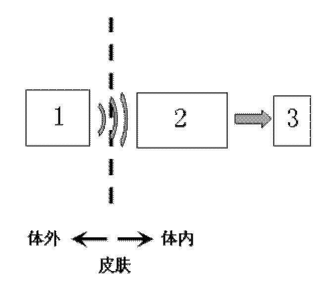
图1是本发明的结构示意图;Fig. 1 is a structural representation of the present invention;
图2是超声声能接收单元的主视图;Fig. 2 is the front view of the ultrasonic sound energy receiving unit;
图3是超声声能接收单元的俯视图;Fig. 3 is a top view of the ultrasonic sound energy receiving unit;
图4是压电悬臂梁的剖面图。Fig. 4 is a cross-sectional view of a piezoelectric cantilever beam.
具体实施方式Detailed ways
下面对本发明的实施例作详细说明,本实施例在以本发明技术方案为前提下进行实施,给出了详细的实施方式和具体的操作过程,但本发明的保护范围不限于下述的实施例。The embodiments of the present invention are described in detail below. This embodiment is implemented on the premise of the technical solution of the present invention, and detailed implementation methods and specific operating procedures are provided, but the protection scope of the present invention is not limited to the following implementation example.
实施例1Example 1
如图1所示,本实施例包括:超声发射单元1、超声声能接收单元2和储能单元3,其中:超声发射单元1设置于体外,超声声能接收单元2和储能单元3设置于体内,储能单元3和超声声能接收单元2相连。As shown in Figure 1, this embodiment includes: an
所述的超声发射单元1包括:体外电路和超声振子,其中:超声振子设置于体外,体外电路驱动超声振子发射超声。The
所述的超声振子是朗之万振子、压电超声振子或者电磁超声振子中的一种,本实施例选用朗之万振子,在体外向体内组织内发射60KHz频率的超声。The ultrasonic vibrator is one of a Langevin vibrator, a piezoelectric ultrasonic vibrator or an electromagnetic ultrasonic vibrator. In this embodiment, the Langevin vibrator is selected to transmit ultrasound at a frequency of 60 KHz in vitro to tissues in the body.
如图2,图3和图4所示,所述的超声声能接收单元2包括:压电振子4和振子封装5,其中:压电振子4接收超声振子发射的超声,压电振子4设于振子封装5的内部。As shown in Fig. 2, Fig. 3 and Fig. 4, the ultrasonic sound
所述的压电振子4是若干个相互平行排列且尺寸相同压电悬臂梁6,压电悬臂梁6的外部气相沉积包覆设置2微米厚的聚合物派瑞林(Parylene)薄膜。The
所述的压电悬臂梁6包括:顶电极层7、压电层8、底电极层9、二氧化硅基体10、硅梁11和硅框架12,其中:二氧化硅基体10的上表面溅射沉积底电极层9,底电极层9上溶胶凝胶有压电层8,压电层8上溅射沉积顶电极层7,二氧化硅基体10的下表面光刻设有硅梁11,硅梁11的底部的一端上光刻有硅框架12,另一端悬空,顶电极层7和底电极层9上键合引线,引线和储能单元3相连。The
本实施例中,压电振子4的尺寸是3毫米×3毫米×0.3毫米,压电层的8厚度是1微米,顶电极层7和底电极层9的厚度是150纳米、二氧化硅基10的厚度是1微米,硅梁11的厚度是15微米,压电层8沿其厚度方向极化。In this embodiment, the size of the
本实施例的振子封装5采用金属壳气密封装,本实施例选用钛壳气密封装。将压电振子4设于振子封装5的钛壳内部,并采用5微米厚的聚合物派瑞林(Parylene)薄膜包裹钛壳。The
所述的聚合物派瑞林(Parylene)薄膜具有生物相容性和良好密封性。The polymer Parylene film has biocompatibility and good sealing performance.
所述的压电振子4以共振方式接收由朗之万振子发射的超声,并通过压电效应将振动能转化为电能,压电振子4的固有频率和朗之万振子的发射频率相同为60KHz。The
所述的储能单元3包括:整流电路、电容和充电电池,其中:整流电路分别与顶电极层7和底电极层9相连,整流电路、充电电池和电容相互并联。单个压电悬臂梁6共振产生的交流电通过顶电极层7和底电极层9输出到全桥整流电路转化为直流电,并将多个整流后的压电悬臂梁6电压输出串联以提高输出电压,给电容器进行充电,并通过电容器给锂充电电池充电。The
实施例2Example 2
本实施例的超声振子选用菲涅耳波带电极的压电超声振子,在体外向体内组织内发射60KHz频率的超声。The ultrasonic vibrator in this embodiment is a piezoelectric ultrasonic vibrator with Fresnel-wave zone electrodes, which transmits ultrasound at a frequency of 60 KHz to tissues in the body outside the body.
本实施例的振子封装5采用多孔聚合物非气密封装,是具有良好生物相容性的聚合物硅橡胶,其内有设有空腔,压电振子4设置在振子封装5的多孔聚合物的空腔内。The
本实施例的其他实施方式和实施例1相同。Other implementation modes of this embodiment are the same as
本实施例的压电振子4以共振方式接收由菲涅耳波带电极的压电超声振子发射的超声,并通过压电效应将振动能转化为电能,压电振子4的固有频率和菲涅耳波带电极的压电超声振子的发射频率相同为60KHz。The
由于聚合物硅橡胶为多孔材料,体内的组织液可渗入空腔,形成一个体液构成的腔体。由于派瑞林(Parylene)薄膜具有良好的覆盖能力,可将压电振子4与组织液隔离,压电振子4实际上工作在液体环境中。Since polymer silicone rubber is a porous material, interstitial fluid in the body can penetrate into the cavity, forming a cavity composed of body fluid. Since the Parylene film has a good covering ability, it can isolate the
Claims (9)
Priority Applications (1)
| Application Number | Priority Date | Filing Date | Title |
|---|---|---|---|
| CN2010101140311A CN101800486B (en) | 2010-02-25 | 2010-02-25 | Resonance type implantable micro-energy device based on ultrasonic energy supply |
Applications Claiming Priority (1)
| Application Number | Priority Date | Filing Date | Title |
|---|---|---|---|
| CN2010101140311A CN101800486B (en) | 2010-02-25 | 2010-02-25 | Resonance type implantable micro-energy device based on ultrasonic energy supply |
Publications (2)
| Publication Number | Publication Date |
|---|---|
| CN101800486A true CN101800486A (en) | 2010-08-11 |
| CN101800486B CN101800486B (en) | 2012-07-04 |
Family
ID=42596024
Family Applications (1)
| Application Number | Title | Priority Date | Filing Date |
|---|---|---|---|
| CN2010101140311A Expired - Fee Related CN101800486B (en) | 2010-02-25 | 2010-02-25 | Resonance type implantable micro-energy device based on ultrasonic energy supply |
Country Status (1)
| Country | Link |
|---|---|
| CN (1) | CN101800486B (en) |
Cited By (9)
| Publication number | Priority date | Publication date | Assignee | Title |
|---|---|---|---|---|
| CN104734374A (en) * | 2015-04-08 | 2015-06-24 | 重庆医科大学 | Wireless charging method based on ultrasound waves |
| CN104767291A (en) * | 2015-04-08 | 2015-07-08 | 重庆医科大学 | Ultrasonic based wireless charging system |
| CN106037643A (en) * | 2016-05-19 | 2016-10-26 | 上海应特宠企业管理有限公司 | Implanted chip and system for continuously detecting mammal signs |
| CN106797207A (en) * | 2014-12-17 | 2017-05-31 | 株式会社村田制作所 | Piezoelectric vibrator and piezoelectric vibration device |
| CN108173331A (en) * | 2018-01-23 | 2018-06-15 | 清华大学 | Ultrasonic wave charging method and device |
| CN109688902A (en) * | 2016-07-18 | 2019-04-26 | 诺威适骨科专科公司 | Communication device and method |
| CN110115800A (en) * | 2019-05-17 | 2019-08-13 | 清华大学 | Flexible drug release micro-system based on ultrasonic wave energy supply |
| CN110290449A (en) * | 2019-05-09 | 2019-09-27 | 安徽奥飞声学科技有限公司 | An audio device and electronic equipment |
| CN112370064A (en) * | 2020-10-28 | 2021-02-19 | 上海交通大学 | Clamping die, auxiliary electrode implantation device utilizing ultrasonic vibration and implantation method |
Family Cites Families (3)
| Publication number | Priority date | Publication date | Assignee | Title |
|---|---|---|---|---|
| CA2539692A1 (en) * | 2003-09-18 | 2005-03-31 | Advanced Bio Prosthetic Surfaces, Ltd. | Medical device having mems functionality and methods of making same |
| AU2006273679B2 (en) * | 2005-07-26 | 2012-05-03 | Menachem P. Weiss | Extending intrabody capsule |
| CN101612451B (en) * | 2009-07-31 | 2011-05-18 | 广东省医疗器械研究所 | Chargeable implant cardiac pacemaker device and charging method thereof |
-
2010
- 2010-02-25 CN CN2010101140311A patent/CN101800486B/en not_active Expired - Fee Related
Cited By (11)
| Publication number | Priority date | Publication date | Assignee | Title |
|---|---|---|---|---|
| CN106797207A (en) * | 2014-12-17 | 2017-05-31 | 株式会社村田制作所 | Piezoelectric vibrator and piezoelectric vibration device |
| CN104734374A (en) * | 2015-04-08 | 2015-06-24 | 重庆医科大学 | Wireless charging method based on ultrasound waves |
| CN104767291A (en) * | 2015-04-08 | 2015-07-08 | 重庆医科大学 | Ultrasonic based wireless charging system |
| CN106037643A (en) * | 2016-05-19 | 2016-10-26 | 上海应特宠企业管理有限公司 | Implanted chip and system for continuously detecting mammal signs |
| CN109688902A (en) * | 2016-07-18 | 2019-04-26 | 诺威适骨科专科公司 | Communication device and method |
| US11389111B2 (en) | 2016-07-18 | 2022-07-19 | Nuvasive Specialized Orthopedics, Inc. | Communication device and methods |
| CN108173331A (en) * | 2018-01-23 | 2018-06-15 | 清华大学 | Ultrasonic wave charging method and device |
| CN108173331B (en) * | 2018-01-23 | 2019-06-18 | 清华大学 | Ultrasonic charging method and device |
| CN110290449A (en) * | 2019-05-09 | 2019-09-27 | 安徽奥飞声学科技有限公司 | An audio device and electronic equipment |
| CN110115800A (en) * | 2019-05-17 | 2019-08-13 | 清华大学 | Flexible drug release micro-system based on ultrasonic wave energy supply |
| CN112370064A (en) * | 2020-10-28 | 2021-02-19 | 上海交通大学 | Clamping die, auxiliary electrode implantation device utilizing ultrasonic vibration and implantation method |
Also Published As
| Publication number | Publication date |
|---|---|
| CN101800486B (en) | 2012-07-04 |
Similar Documents
| Publication | Publication Date | Title |
|---|---|---|
| CN101800486B (en) | Resonance type implantable micro-energy device based on ultrasonic energy supply | |
| Hong et al. | A wood-templated unidirectional piezoceramic composite for transmuscular ultrasonic wireless power transfer | |
| Jiang et al. | Flexible lead-free piezoelectric arrays for high-efficiency wireless ultrasonic energy transfer and communication | |
| US7580750B2 (en) | Implantable medical device with integrated acoustic transducer | |
| Haq | Application of piezo transducers in biomedical science for health monitoring and energy harvesting problems | |
| Jia et al. | A wireless ultrasound energy harvester based on flexible relaxor ferroelectric crystal composite arrays for implanted bio-electronics | |
| CN110011565B (en) | An energy harvester and an implantable self-powered medical electronic device | |
| CN103795291B (en) | Miniature implanted ultrasonic resonance wireless energy transmits receptor and preparation method thereof | |
| Shih et al. | Design, fabrication, and application of bio-implantable acoustic power transmission | |
| Fadhel et al. | Used methods to wirelessly powered implantable medical devices | |
| CN113078255B (en) | Wireless charging device for bio-implant device | |
| CN109674457A (en) | A kind of implantable medical detection device | |
| CN214626523U (en) | Implantable flexible wireless energy supply device based on ultrasonic energy conversion | |
| Zitouni et al. | Piezoelectric energy harvesting for wearable and implantable devices | |
| KR20230144271A (en) | Structures comprising triboelectric generator drived by ultrasonic waves, and nerve stimulation platform | |
| Singh et al. | Piezoelectric Energy Harvesting for Pacemaker Applications: Current State-of-the-Art, Materials, Design, and Alternative Technologies | |
| CN204840675U (en) | Active medical devices of rechargeable implanted and system thereof | |
| CN104740762B (en) | Self energizing brain pacemaker | |
| CN104740768A (en) | Self-energized cardiac pacemaker | |
| Abduljaleel et al. | Survey of near-field wireless communication and power transfer for biomedical implants | |
| CN104740759B (en) | Heart nanometer generating system | |
| CN204072105U (en) | Implanted self energizing blood sugar monitoring instrument | |
| CN103078413B (en) | Energy supply device for implantable sensor and receiving device of implantable sensor | |
| CN204073100U (en) | Self energizing brain pacemaker | |
| CN204073105U (en) | Implanted self energizing cardioverter-defibrillator |
Legal Events
| Date | Code | Title | Description |
|---|---|---|---|
| C06 | Publication | ||
| PB01 | Publication | ||
| C10 | Entry into substantive examination | ||
| SE01 | Entry into force of request for substantive examination | ||
| C14 | Grant of patent or utility model | ||
| GR01 | Patent grant | ||
| CF01 | Termination of patent right due to non-payment of annual fee |
Granted publication date: 20120704 Termination date: 20150225 |
|
| EXPY | Termination of patent right or utility model |