CN101784416A - Seat back structure of vehicle seats and retaining structure for a crank member - Google Patents
Seat back structure of vehicle seats and retaining structure for a crank member Download PDFInfo
- Publication number
- CN101784416A CN101784416A CN200880101184A CN200880101184A CN101784416A CN 101784416 A CN101784416 A CN 101784416A CN 200880101184 A CN200880101184 A CN 200880101184A CN 200880101184 A CN200880101184 A CN 200880101184A CN 101784416 A CN101784416 A CN 101784416A
- Authority
- CN
- China
- Prior art keywords
- pressure receiving
- receiving member
- seat back
- support
- headrest
- Prior art date
- Legal status (The legal status is an assumption and is not a legal conclusion. Google has not performed a legal analysis and makes no representation as to the accuracy of the status listed.)
- Pending
Links
Images


Classifications
-
- B—PERFORMING OPERATIONS; TRANSPORTING
- B60—VEHICLES IN GENERAL
- B60N—SEATS SPECIALLY ADAPTED FOR VEHICLES; VEHICLE PASSENGER ACCOMMODATION NOT OTHERWISE PROVIDED FOR
- B60N2/00—Seats specially adapted for vehicles; Arrangement or mounting of seats in vehicles
- B60N2/80—Head-rests
- B60N2/888—Head-rests with arrangements for protecting against abnormal g-forces, e.g. by displacement of the head-rest
-
- B—PERFORMING OPERATIONS; TRANSPORTING
- B60—VEHICLES IN GENERAL
- B60N—SEATS SPECIALLY ADAPTED FOR VEHICLES; VEHICLE PASSENGER ACCOMMODATION NOT OTHERWISE PROVIDED FOR
- B60N2/00—Seats specially adapted for vehicles; Arrangement or mounting of seats in vehicles
- B60N2/24—Seats specially adapted for vehicles; Arrangement or mounting of seats in vehicles for particular purposes or particular vehicles
- B60N2/42—Seats specially adapted for vehicles; Arrangement or mounting of seats in vehicles for particular purposes or particular vehicles the seat constructed to protect the occupant from the effect of abnormal g-forces, e.g. crash or safety seats
- B60N2/427—Seats or parts thereof displaced during a crash
- B60N2/42772—Seats or parts thereof displaced during a crash characterised by the triggering system
- B60N2/42781—Seats or parts thereof displaced during a crash characterised by the triggering system mechanical triggering
-
- B—PERFORMING OPERATIONS; TRANSPORTING
- B60—VEHICLES IN GENERAL
- B60N—SEATS SPECIALLY ADAPTED FOR VEHICLES; VEHICLE PASSENGER ACCOMMODATION NOT OTHERWISE PROVIDED FOR
- B60N2/00—Seats specially adapted for vehicles; Arrangement or mounting of seats in vehicles
- B60N2/80—Head-rests
- B60N2/806—Head-rests movable or adjustable
- B60N2/838—Tiltable
- B60N2/853—Tiltable characterised by their adjusting mechanisms, e.g. electric motors
Landscapes
- Engineering & Computer Science (AREA)
- Aviation & Aerospace Engineering (AREA)
- Transportation (AREA)
- Mechanical Engineering (AREA)
- Seats For Vehicles (AREA)
- Chair Legs, Seat Parts, And Backrests (AREA)
Abstract
Description
相关申请的交叉引用Cross References to Related Applications
本申请根据35U.S.C§119(a)-(d)要求2007年7月31日提交的JP 2007-198558、2007年8月14日提交的JP 2007-211334的外国优选权,并且要求2008年4月2日提交的美国临时申请序列号61/041,715的权益,这些专利通过引用全文并入于此。This application claims foreign priority under 35 U.S.C § 119(a)-(d) of JP 2007-198558 filed July 31, 2007, JP 2007-211334 filed August 14, 2007, and claims 2008 The benefit of US Provisional Application Serial No. 61/041,715, filed April 2, which is hereby incorporated by reference in its entirety.
背景background
1.技术领域1. Technical field
本发明的实施方式涉及交通工具座椅的座椅靠背结构,其通过使设置在座椅靠背内部的预定的压力接收构件接收由后端碰撞产生的由乘客经历的向后方向上的惯性的转移,来强迫地改变头枕在上部方向以及前面方向上的位置。An embodiment of the present invention relates to a seat back structure of a vehicle seat by causing a predetermined pressure receiving member provided inside the seat back to receive transfer of inertia in a rearward direction experienced by a passenger resulting from a rear-end collision, to forcibly change the position of the headrest in the upper direction as well as in the front direction.
本发明的实施方式还涉及用于曲柄构件的保持结构,其以可圆形移动的方式将曲柄构件保持在具有插入孔的左支撑构件和右支撑构件之间。Embodiments of the present invention also relate to a retaining structure for a crank member that retains the crank member in a circularly movable manner between left and right support members having insertion holes.
2.背景技术2. Background technology
交通工具座椅的座椅靠背结构通过使设置在座椅靠背内部的预定的压力接收构件接收在后端碰撞发生时由乘客经历的向后方向上的惯性的转移产生的载荷(冲击载荷),来强迫地改变头枕在,例如,上部方向以及前面方向上的位置,其中上部方向以及前面方向是乘客的头部移动的方向,这种交通工具座椅的座椅靠背结构已经公开在例如,Kokai的官方公报No.:Hei11(1999)-034708以及其他文献中。The seat back structure of the vehicle seat realizes the load (impact load) generated by the transfer of inertia in the rearward direction experienced by a passenger when a rear-end collision occurs by a predetermined pressure receiving member provided inside the seat back. Forcibly changing the position of the headrest in, for example, the upper direction and the front direction, wherein the upper direction and the front direction are the directions in which the passenger's head moves, the seat back structure of such a vehicle seat has been disclosed in, for example, Kokai Official Gazette No.: Hei11(1999)-034708 and other documents.
这种类型的头枕,即所谓的紧急启动头枕(emergency-activated headrest),通常由来自由拉伸螺旋弹簧等组成的供能装置的供能力(energizingforce)提供能量,且被保持在其通常的支撑位置,即被保持在其下部初始位置;且该供能力通常被设置成由后端碰撞产生的冲击载荷的输入评判标准。除了以上内容之外,当超过设定的供能力的载荷(冲击载荷)被输入压力接收构件时,压力接收构件在向后方向上移动来抵抗供能力;通过上述动作,头枕被构建成从其下部初始位置转移到上部改变位置,其是上部方向和向前方向。This type of headrest, the so-called emergency-activated headrest, is usually powered by an energizing force from an energizing device consisting of a tension coil spring or the like, and is kept at its usual The support position, that is, is held in its lower initial position; and the supply capacity is usually set as an input criterion for impact loads resulting from rear-end collisions. In addition to the above, when a load (impact load) exceeding the set supply capacity is input to the pressure receiving member, the pressure receiving member moves in the rearward direction against the supply capacity; by the above-mentioned action, the headrest is constructed to be free from its The lower initial position is transferred to the upper changed position, which is the upper direction and the forward direction.
根据如上所述的这种构造,在后端碰撞发生时,头枕移动到更靠近乘客的头部的位置,且头枕和乘客的头部之间的空间变窄了;因此,头部向后倾斜的程度被降低,其中该倾斜是在后端碰撞发生时产生的。因此,可降低在后端碰撞发生时由头部的突然倾斜引起的对颈部的损害,即所谓的鞭样伤害(whip-lash)。According to such a configuration as described above, when a rear-end collision occurs, the headrest moves to a position closer to the passenger's head, and the space between the headrest and the passenger's head becomes narrow; The degree of rear lean that occurs in the event of a rear-end collision is reduced. Therefore, it is possible to reduce damage to the neck caused by a sudden tilt of the head when a rear-end collision occurs, that is, a so-called whip-lash.
在上述Kokai的官方公报No.:Hei11(1999)-034708中公开的构造中,用于接收来自向后方向上的惯性的转移的冲击载荷的压力接收构件被设置在对应于乘客的背部部分的位置。一般来说,在乘客的正常驾驶姿势下,乘客的骨盆区域大部分与座椅靠背的就座表面接触,而乘客的背部部分倾向于与座椅靠背的就座表面分开。因为上述倾向,当向后方向上的惯性的转移通过后端碰撞而被施加时,乘客的背部部分至少首先经过间隔距离,然后才能到达压力接收构件,并按压该构件。换句话说,在后端碰撞发生时,由于该间隔距离,乘客的背部部分以伪方式与由大的供能力供能和保持的压力接收构件碰撞;因此,可能的是:当头枕启动时,乘客的背部部分将被迫接收过量程度的冲击载荷,而不能被拒绝。In the configuration disclosed in Kokai's Official Gazette No.: Hei11(1999)-034708 mentioned above, the pressure receiving member for receiving the impact load from the transfer of inertia in the rearward direction is provided at a position corresponding to the passenger's back portion . Generally, in the normal driving position of the passenger, the passenger's pelvic region is mostly in contact with the seating surface of the seat back, while the passenger's back portion tends to separate from the seating surface of the seat back. Because of the above tendency, when a shift of inertia in the rearward direction is applied by a rear-end collision, the passenger's back portion at least first passes through the separation distance before reaching the pressure receiving member and pressing it. In other words, when a rear-end collision occurs, due to the separation distance, the back portion of the passenger collides with the pressure receiving member energized and held by a large power supply force in a pseudo manner; therefore, it is possible that when the headrest is activated, The back portion of the passenger will be forced to receive shock loads of an excessive degree and cannot be rejected.
与如上所述的构造相比,Kokai的官方公报No.:2000-325179公开了这样一种构造,其中,头枕通过使乘客的骨盆区域压靠压力接收构件而被紧急启动至其上部改变位置。一般来说,在乘客的正常驾驶姿势下,乘客的骨盆区域大部分与座椅靠背的就座表面接触;因此,乘客的骨盆区域在没有经过间隔距离的情况下就到达压力接收构件并按压压力接收构件。因此,如果座椅靠背以乘客的骨盆区域按压压力接收构件的方式构建,则当压力接收构件被按压时,施加到乘客的冲击载荷将被降低。Compared with the configuration described above, Kokai's Official Gazette No.: 2000-325179 discloses a configuration in which the headrest is emergency actuated to its upper changing position by pressing the occupant's pelvic region against the pressure receiving member . In general, in the normal driving posture of the passenger, most of the pelvic region of the passenger is in contact with the seating surface of the seat back; therefore, the pelvic region of the passenger reaches the pressure receiving member and presses the pressure without passing through the separation distance. Receive artifacts. Therefore, if the seat back is constructed in such a way that the occupant's pelvic region presses the pressure receiving member, the impact load applied to the occupant will be reduced when the pressure receiving member is pressed.
例如,如Kokai的官方公报No.:Hei10(1998)-138812中公开的,常规的曲柄构件的左臂和右臂被形成为直线形状,即没有施加处理的水平形状。此外,水平形状的臂被插入到设置在类似座椅靠背框架的左侧框架和右侧框架的支撑构件上的插入孔中,且衬套螺母(bushing nut)和E环(E ring)被安装到从插入孔伸出的臂上,使得曲柄构件以可圆形移动的方式保持在支撑构件之间。For example, as disclosed in Kokai's Official Gazette No.: Hei 10(1998)-138812, the left and right arms of the conventional crank member are formed in a linear shape, that is, a horizontal shape without processing. In addition, horizontally shaped arms are inserted into insertion holes provided on support members of the left and right frames like the seat back frame, and bushing nuts and E rings are installed. to the arm protruding from the insertion hole so that the crank member is held between the support members in a circularly movable manner.
概述overview
1.本发明要解决的问题1. The problem to be solved in the present invention
供能力由供能装置产生,且被施加至头枕和压力接收构件,一般来说,在头枕的整个可移动范围内,供能力被持续地施加至头枕和压力接收构件。因此,为了将头枕以稳定的方式保持在其上部改变位置,有必要对压力接收构件连续地施加大于供能力的压力的量来抵抗该供能力。The power supply is generated by the energy supply device, and is applied to the headrest and the pressure receiving member, generally, the power supply is continuously applied to the headrest and the pressure receiving member throughout the entire movable range of the headrest. Therefore, in order to hold the headrest in its upper changed position in a stable manner, it is necessary to continuously apply an amount of pressure greater than the supply capacity to the pressure receiving member against the supply capacity.
然而,乘客的上部躯体沉靠在座椅靠背上的程度倾向于:关于乘客的背部部分较大,而非关于乘客的骨盆区域较大。当乘客的背部部分较大程度上沉入座椅靠背时,由乘客的骨盆区域产生的且施加到压力接收构件的输入载荷倾向于由于随着乘客的姿势改变而改变的重力中心以及此时的其他因素而减小。因此,在来自乘客的骨盆区域的载荷按压压力接收构件的构造中,将头枕保持在上部改变位置的稳定性可依靠减小的压力的程度而降低。However, the degree to which the occupant's upper torso sinks against the seat back tends to be larger with respect to the occupant's back than with the occupant's pelvic region. When the back portion of the passenger sinks into the seat back to a large extent, the input load generated by the pelvic area of the passenger and applied to the pressure receiving member tends to be due to the center of gravity that changes as the passenger's posture changes and the reduced by other factors. Therefore, in the configuration in which the load from the occupant's pelvic region presses the pressure receiving member, the stability of maintaining the headrest in the upper changed position can be reduced by the degree of reduced pressure.
换句话说,在乘客的背部部分按压压力接收构件的构造中,在初始启动时,乘客的背部部分可能被迫接收过量程度的冲击载荷,且乘客的骨盆区域可能不连续地按压压力接收构件。In other words, in the configuration in which the occupant's back portion presses the pressure receiving member, the occupant's back portion may be forced to receive an excessive degree of impact load at the time of initial start-up, and the occupant's pelvic region may discontinuously press the pressure receiving member.
本发明的实施方式用于提供一种交通工具座椅的座椅靠背结构,其中,在初始启动时,乘客的背部部分不被迫接收过量程度的冲击载荷,且其中,乘客的骨盆区域能够连续地按压压力接收构件。Embodiments of the present invention are intended to provide a seat back structure of a vehicle seat in which the passenger's back portion is not forced to receive an excessive degree of impact load at the time of initial start-up, and in which the passenger's pelvic region can continuously Press the pressure receiving member firmly.
然而,当使用衬套螺母时,对曲柄构件的臂边缘应用台阶成型工艺(astep-forming process)变得必要,且当使用E环时,对曲柄构件的臂边缘应用圆形槽成型工艺(circular-groove-forming process)变得必要。这种台阶成型工艺和圆形槽成型工艺是特殊的工艺,它们不同于用来形成曲柄构件的弯曲工艺,且因此成本高。However, when a bushing nut is used, it becomes necessary to apply a step-forming process to the arm edge of the crank member, and when an E-ring is used, to apply a circular groove-forming process to the arm edge of the crank member. -groove-forming process) becomes necessary. This step forming process and the circular groove forming process are special processes that are different from the bending process used to form the crank member and are therefore costly.
此外,需要特殊的工具来安装衬套螺母和E环;因此,可操作性不可避免地降低。In addition, a special tool is required to install the bushing nut and the E ring; therefore, workability is inevitably reduced.
此外,在曲柄构件的水平形状的臂被插入到支撑构件的插入孔中且曲柄构件被保持在其中的构造中,当过量载荷被施加到曲柄构件时,该载荷以集中的方式作用在衬套螺母和E环上,其中该衬套螺母和E环用于防止该臂脱落。结果,当能够引起变形的过量载荷被施加时,衬套螺母和E环不能抵抗该载荷,且它们破裂。因此,存在臂从支撑构件的插入孔中脱落的风险。Furthermore, in a configuration in which the horizontally shaped arm of the crank member is inserted into the insertion hole of the support member and the crank member is held therein, when an excessive load is applied to the crank member, the load acts on the bushing in a concentrated manner. on the nut and E ring where the bushing nut and E ring are used to prevent the arm from falling out. As a result, when an excessive load capable of causing deformation is applied, the bushing nut and E-ring cannot resist the load and they break. Therefore, there is a risk that the arm falls out of the insertion hole of the supporting member.
本发明的至少一个实施方式的目的是提供一种降低了成本的用于曲柄构件的保持结构,且其中,尽管其结构简单,但臂不会从插入孔中脱落。An object of at least one embodiment of the present invention is to provide a cost-reduced holding structure for a crank member in which an arm does not fall out of an insertion hole despite its simple structure.
2.用于解决问题的手段2. The means used to solve the problem
根据本发明的至少一个实施方式,本发明的该至少一个实施方式的特性如下:According to at least one embodiment of the present invention, the characteristics of this at least one embodiment of the present invention are as follows:
交通工具座椅的座椅靠背结构,其通过使设置在座椅靠背内部的预定的压力接收构件接收由后端碰撞产生的由乘客经历的向后方向上的惯性的转移,来强迫地改变头枕在上部方向以及前面方向上的位置;A seat back structure of a vehicle seat that forcibly changes the headrest by causing a predetermined pressure receiving member provided inside the seat back to receive a transfer of inertia in the rearward direction experienced by a passenger resulting from a rear-end collision position in the upper direction as well as in the front direction;
其中,一对左圆形移动连杆和右圆形移动连杆(a pair of left and rightcircularly moving links),其分别安装在座椅靠背框架的左侧构件和右侧构件上,以便能够摇摆;Among them, a pair of left circularly moving links and right circularly moving links (a pair of left and right circularly moving links), which are respectively installed on the left and right members of the seat back frame so as to be able to swing;
支撑轴,其被横向地设置成横跨着悬挂在该对左圆形移动连杆和右圆形移动连杆的预定的边缘,使得当圆形移动连杆圆形地移动时,沿着圆弧在上部方向和下部方向上的移动成为可能;a support shaft which is laterally arranged to straddle predetermined edges suspended from the pair of left and right circular moving links so that when the circular moving links move circularly, The movement of the arc in the upper and lower direction becomes possible;
柱状保持器支架(cylinder-like holder bracket),其被插入到头枕支柱中并由头枕支柱支撑,该头枕支柱以与支撑轴成一体的方式设置,且支架被设计成穿过固定在座椅靠背框架的上部构件上的支架导向件,以便与支架导向件接触地自由滑动,且以便自由倾斜;A cylinder-like holder bracket which is inserted into and supported by a headrest strut which is provided integrally with the support shaft and which is designed to pass through and be fixed to the seat a bracket guide on the upper member of the back frame to slide freely in contact with the bracket guide and to tilt freely;
因此,当圆形移动连杆抵抗上述供能力而圆形地移动时,能够确保头枕处于上部改变位置,同时以支架导向件为支点而向前倾斜;Therefore, when the circular moving link circularly moves against the above-mentioned supplying force, it is possible to ensure that the headrest is in the upper changing position while tilting forward with the bracket guide as a fulcrum;
上述压力接收构件经由其上端固定到支撑轴上,以便响应于支撑轴而移动,且上述压力接收构件被设计成在下部方向上延伸的压力接收构件,以便接收来自乘客的骨盆区域和背部部分的载荷;The above-mentioned pressure receiving member is fixed to the support shaft via its upper end so as to move in response to the support shaft, and the above-mentioned pressure receiving member is designed as a pressure receiving member extending in a lower direction so as to receive pressure from a passenger's pelvic area and back portion. load;
且上述压力接收构件由曲柄构件支撑,该曲柄构件被设置成横跨着悬挂在座椅靠背的左方向和右方向上,并被支撑为可借助于轴进行旋转,且横向地设置成使得在向后方向和上部方向上的圆形移动成为可能。And the above-mentioned pressure receiving member is supported by a crank member which is arranged to straddle and hang in the left and right directions of the seat back and is supported to be rotatable by means of a shaft, and is arranged laterally so that in Circular movements in the rearward direction and the upper direction are possible.
根据本发明的至少一个实施方式,本发明的该至少一个实施方式的特性如下:According to at least one embodiment of the present invention, the characteristics of this at least one embodiment of the present invention are as follows:
交通工具座椅的座椅靠背结构,其通过使设置在座椅靠背内部的预定的压力接收构件接收由后端碰撞产生的由乘客经历的向后方向上的惯性的转移,来强迫地改变头枕在上部方向以及前面方向上的位置;A seat back structure of a vehicle seat that forcibly changes the headrest by causing a predetermined pressure receiving member provided inside the seat back to receive a transfer of inertia in the rearward direction experienced by a passenger resulting from a rear-end collision position in the upper direction as well as in the front direction;
其中,一对左圆形移动连杆和右圆形移动连杆,其分别安装在座椅靠背框架的左侧构件和右侧构件上,以便能够摇摆;Among them, a pair of left circular moving links and right circular moving links, which are respectively installed on the left and right members of the seat back frame so as to be able to swing;
支撑轴,其被横向地设置成横跨着悬挂在该对左圆形移动连杆和右圆形移动连杆的预定的边缘,使得当圆形移动连杆圆形地移动时,沿着圆弧在上部方向和下部方向上的移动成为可能;a support shaft which is laterally arranged to straddle predetermined edges suspended from the pair of left and right circular moving links so that when the circular moving links move circularly, The movement of the arc in the upper and lower direction becomes possible;
柱状保持器支架,其被插入到头枕支柱中并由头枕支柱支撑,该头枕支柱以与支撑轴成一体的方式设置,且支架被设计成穿过固定在座椅靠背框架的上部构件上的支架导向件,以便与支架导向件接触地自由滑动,且以便自由倾斜;A post-shaped holder bracket inserted into and supported by a headrest post provided integrally with a support shaft, and the bracket is designed to pass through a a bracket guide for freely sliding in contact with the bracket guide and for free tilting;
因此,当圆形移动连杆抵抗上述供能力而圆形地移动时,能够确保头枕处于上部改变位置,同时以支架导向件为支点而向前倾斜;Therefore, when the circular moving link circularly moves against the above-mentioned supplying force, it is possible to ensure that the headrest is in the upper changing position while tilting forward with the bracket guide as a fulcrum;
上述压力接收构件经由其上端固定到支撑轴上,以便响应于支撑轴而移动,且上述压力接收构件被设计成在下部方向上延伸的压力接收构件,以便接收来自乘客的骨盆区域和背部部分的载荷;The above-mentioned pressure receiving member is fixed to the support shaft via its upper end so as to move in response to the support shaft, and the above-mentioned pressure receiving member is designed as a pressure receiving member extending in a lower direction so as to receive pressure from a passenger's pelvic area and back portion. load;
且上述压力接收构件由曲柄构件支撑,该曲柄构件被设置成横跨着悬挂在座椅靠背的左方向和右方向上,并被支撑为可借助于轴进行旋转,且横向地设置成使得在向后方向和上部方向上的圆形移动成为可能,且曲柄构件的圆形移动通过支撑连杆传递至圆形移动连杆,成为圆形移动连杆抵抗供能力的圆形移动。And the above-mentioned pressure receiving member is supported by a crank member which is arranged to straddle and hang in the left and right directions of the seat back and is supported to be rotatable by means of a shaft, and is arranged laterally so that in Circular movement in the rearward direction and the upper direction is possible, and the circular movement of the crank member is transmitted to the circular movement link through the support link, becoming the circular movement of the circular movement link against the power supply.
根据本发明的至少一个实施方式,本发明的该至少一个实施方式的特性如下:According to at least one embodiment of the present invention, the characteristics of this at least one embodiment of the present invention are as follows:
交通工具座椅的座椅靠背结构,Seat back structures for vehicle seats,
其中,上述压力接收构件被形成为从前面看近似字母U的形状,且具有一对竖直轴和水平轴,该对竖直轴使得压力接收构件能够接收来自乘客的背部部分的载荷,该水平轴使得压力接收构件能够接收来自乘客的骨盆区域的载荷。Wherein, the above-mentioned pressure receiving member is formed in a shape approximate to the letter U when viewed from the front, and has a pair of vertical shafts and a horizontal shaft that enable the pressure receiving member to receive a load from the passenger's back portion, the horizontal shaft The shaft enables the pressure receiving member to receive loads from the occupant's pelvic region.
根据本发明的至少一个实施方式,本发明的该至少一个实施方式的特性如下:According to at least one embodiment of the present invention, the characteristics of this at least one embodiment of the present invention are as follows:
交通工具座椅的座椅靠背结构,Seat back structures for vehicle seats,
其中,支架导向件配备有前壁和后壁,该前壁和后壁各自具有第一支撑面和第二支撑面,该第一支撑面的倾斜角度对应于保持器支架处于头枕的下部初始位置时的角度,而该第二支撑面的倾斜角度对应于保持器支架处于头枕的上部改变位置时的角度,Wherein, the bracket guide is equipped with a front wall and a rear wall, the front wall and the rear wall respectively have a first support surface and a second support surface, the angle of inclination of the first support surface corresponds to the initial position of the retainer bracket in the lower part of the headrest. position, and the angle of inclination of the second support surface corresponds to the angle when the retainer bracket is in the upper part of the headrest and changes position,
且前壁和后壁的第一支撑面和第二支撑面在不同水平处交替地形成为能够将保持器支架夹在中间的平行的平面。Moreover, the first supporting surface and the second supporting surface of the front wall and the rear wall are alternately formed at different levels as parallel planes capable of sandwiching the retainer bracket.
根据本发明的至少一个实施方式,曲柄构件的左臂边缘和右臂边缘分别被弯曲成近似字母L的形状;According to at least one embodiment of the present invention, the left arm edge and the right arm edge of the crank member are respectively bent into a shape approximate to the letter L;
钥匙孔状形状的插入孔,其始于较大直径孔,并连续地延伸至较小直径的长孔,该插入孔被形成在左支撑构件和右支撑构件中的每一个上,且该插入孔的长度使得曲柄构件的臂边缘的近似字母L形的部分可以在水平的方向上插入到插入孔中;An insertion hole of a keyhole-like shape starting from a larger-diameter hole and continuously extending to a smaller-diameter elongated hole is formed on each of the left support member and the right support member, and the insertion hole The length of the hole is such that the approximate L-shaped portion of the arm edge of the crank member can be inserted into the insertion hole in the horizontal direction;
以及衬套,其被设计成能够配合在插入孔的较大直径孔内,且被设置成围绕曲柄构件的臂,且衬套被配合到插入孔的较大直径孔中;因此,曲柄构件被保持在左支撑构件和右支撑构件之间。and a bushing which is designed to fit within the larger diameter hole of the insertion hole and is arranged around the arm of the crank member, and the bushing is fitted into the larger diameter hole of the insertion hole; thus, the crank member is Hold between the left support member and the right support member.
根据本发明的至少一个实施方式,衬套由硬橡胶或塑料形成,且以一体的方式包括其主体和凸缘部分,该主体被设计成能够与插入孔的较大直径孔配合在一起,且该凸缘部分的直径大于较大直径孔的直径;According to at least one embodiment of the invention, the bushing is formed of hard rubber or plastic and comprises in one piece its main body and flange portion, the main body being designed to fit together with the larger diameter hole of the insertion hole, and the diameter of the flange portion is greater than the diameter of the larger diameter hole;
接合件,其与较大直径孔的周边接合,并将支撑构件夹在该接合件和凸缘部分之间的空间中,且该接合件被形成在衬套的主体的外周表面上。An engaging piece that engages with the periphery of the larger diameter hole and sandwiches the support member in the space between the engaging piece and the flange portion is formed on the outer peripheral surface of the main body of the bushing.
根据本发明的至少一个实施方式,接合件形成在衬套的主体的外周表面上的多个分开的位置。According to at least one embodiment of the invention, the engagement members are formed at a plurality of separate locations on the outer peripheral surface of the main body of the bushing.
根据本发明的至少一个实施方式,插入孔的长孔在不与载荷被施加的方向相同的方向上延伸,且插入孔形成在不与臂边缘的近似字母L形的部分的圆形移动范围重叠的位置。According to at least one embodiment of the present invention, the long hole of the insertion hole extends in a direction other than the direction in which the load is applied, and the insertion hole is formed so as not to overlap the circular movement range of the approximately L-shaped portion of the edge of the arm. s position.
3.本发明的效果3. Effects of the present invention
根据本发明的至少一个实施方式,在后端碰撞发生时,由于由乘客的骨盆区域施加的载荷,压力接收构件在向后方向和上部方向上圆形地移动曲柄构件,且同时移动至向后方向和上部方向,以圆形地移动圆形移动连杆;因此,尽管在初始启动时,来自乘客的骨盆区域的载荷被施加到压力接收构件,但在由乘客的骨盆区域施加载荷之后,由乘客的背部部分施加的载荷作用于压力接收构件上。因此,在接收了来自乘客的骨盆区域和背部部分的载荷的情况下,压力接收构件在向后方向和上部方向上移动,以使圆形移动连杆圆形地移动至头枕的上部改变位置;且头枕被平滑地移动至其上部改变位置。然后,通过使压力接收构件接收来自乘客的骨盆区域和背部部分的载荷,使头枕能够继续保持在其上部改变位置。According to at least one embodiment of the present invention, when a rear-end collision occurs, due to the load applied by the passenger's pelvic region, the pressure receiving member circularly moves the crank member in the rearward direction and the upper direction, and simultaneously moves to the rearward direction. direction and upper direction, to circularly move the circular movement link; therefore, although at the initial start-up, the load from the pelvic region of the passenger is applied to the pressure receiving member, after the load is applied by the pelvic region of the passenger, the load is applied by the pelvic region of the passenger The load applied by the passenger's back portion acts on the pressure receiving member. Therefore, in the case of receiving the load from the pelvic area and back portion of the occupant, the pressure receiving member moves in the rearward direction and the upper direction, so that the circular moving link circularly moves to the upper changing position of the headrest ; and the headrest is smoothly moved to its upper changing position. Then, by causing the pressure receiving member to receive the load from the pelvic region and back portion of the passenger, the headrest can be continuously maintained at its upper portion changed position.
除了以上内容之外,因为在初始启动时,压力接收构件是由于施加至其的来自乘客的骨盆区域的载荷而移动的,因此,在初始启动中没有过量载荷施加到乘客的背部部分。In addition to the above, since the pressure receiving member moves due to the load applied thereto from the occupant's pelvic region at the time of the initial start, no excessive load is applied to the back portion of the passenger in the initial start.
换句话说,根据本发明的至少一个实施方式的构造,能够容易地实现初始启动性能(initial activation performance)和启动维持性能(activationmaintenance performance),其中,初始启动性能并不将冲击载荷强迫地施加至乘客,而启动维持性能并不依靠来自乘客的骨盆区域的载荷。In other words, according to the configuration of at least one embodiment of the present invention, it is possible to easily realize initial activation performance (initial activation performance) and activation maintenance performance (activation maintenance performance), wherein the initial activation performance does not forcibly apply a shock load to occupant, while the startup maintains performance does not rely on loads from the occupant's pelvic region.
此外,在发生后端碰撞,压力接收构件接收了来自乘客的骨盆区域和背部部分的载荷时,压力接收构件可在向后方向上移动,这可简单地通过将压力接收构件连接到可圆形移动的曲柄构件来实现,而这有助于简化构造。此外,所需的构件仅仅是这两种构件,即,压力接收构件和曲柄构件,且这些构件可简单地通过将压力接收构件连接到可圆形移动的曲柄构件来装配;该装配不需要高水平的精度,且它可以快速地且容易地进行。此外,压力接收构件能够随着它的自由移动而在向后方向上移动;因此,它能够快速地移动,且它能够具有高水平的可操作性。In addition, when a rear-end collision occurs and the pressure receiving member receives loads from the pelvic region and back portion of the passenger, the pressure receiving member can move in the rearward direction simply by connecting the pressure receiving member to a circularly movable The crank member is realized, and this helps to simplify the construction. In addition, the required members are only these two members, namely, the pressure receiving member and the crank member, and these members can be assembled simply by connecting the pressure receiving member to the circularly movable crank member; level of precision, and it can be done quickly and easily. In addition, the pressure receiving member can move in the rearward direction along with its free movement; therefore, it can move quickly, and it can have a high level of operability.
根据本发明的至少一个实施方式,在后端碰撞发生时,由于由乘客的骨盆区域施加的载荷,压力接收构件在向后方向和上部方向上圆形地移动曲柄构件,且同时移动至向后方向和上部方向,以圆形地移动圆形移动连杆;因此,尽管在初始启动时,来自乘客的骨盆区域的载荷被施加到压力接收构件,但在由乘客的骨盆区域施加载荷之后,由乘客的背部部分施加的载荷作用于压力接收构件上。因此,在接收了来自乘客的骨盆区域和背部部分的载荷的情况下,压力接收构件在向后方向和上部方向上移动,以使圆形移动连杆圆形地移动至头枕的上部改变位置;且头枕被平滑地移动至其上部改变位置。然后,通过使压力接收构件接收来自乘客的骨盆区域和背部部分的载荷,使头枕能够继续保持在其上部改变位置。According to at least one embodiment of the present invention, when a rear-end collision occurs, due to the load applied by the passenger's pelvic region, the pressure receiving member circularly moves the crank member in the rearward direction and the upper direction, and simultaneously moves to the rearward direction. direction and upper direction, to circularly move the circular movement link; therefore, although at the initial start-up, the load from the pelvic region of the passenger is applied to the pressure receiving member, after the load is applied by the pelvic region of the passenger, the load is applied by the pelvic region of the passenger The load applied by the passenger's back portion acts on the pressure receiving member. Therefore, in the case of receiving the load from the pelvic area and back portion of the occupant, the pressure receiving member moves in the rearward direction and the upper direction, so that the circular moving link circularly moves to the upper changing position of the headrest ; and the headrest is smoothly moved to its upper changing position. Then, by causing the pressure receiving member to receive the load from the pelvic region and back portion of the passenger, the headrest can be continuously maintained at its upper portion changed position.
除了以上内容之外,因为在初始启动时,压力接收构件是由于施加至其的来自乘客的骨盆区域的载荷而移动的,因此,在初始启动中没有过量载荷施加到乘客的背部部分。In addition to the above, since the pressure receiving member moves due to the load applied thereto from the occupant's pelvic region at the time of the initial start, no excessive load is applied to the back portion of the passenger in the initial start.
因为由曲柄构件的圆形移动产生的按压载荷被施加到圆形移动连杆,且曲柄构件的圆形移动被有效地利用,所以,圆形移动连杆可更快速且更精确地旋转,且圆形移动连杆的初始启动以及圆形移动的继续都能够得到确保,而不会使冲击载荷强迫地施加到乘客;因此,在施加按压载荷时,施加到乘客的骨盆区域和背部部分的冲击载荷可被降低。Since the pressing load generated by the circular movement of the crank member is applied to the circular movement link, and the circular movement of the crank member is effectively utilized, the circular movement link can be rotated more quickly and precisely, and The initial activation of the circular movement link and the continuation of the circular movement can be ensured without the impact load being forcibly applied to the passenger; Loads can be reduced.
还根据本发明的至少一个实施方式的构造,能够容易地实现初始启动性能和启动维持性能,其中,初始启动性能并不将冲击载荷强迫地施加至乘客,而启动维持性能并不依靠来自乘客的骨盆区域的载荷。Also according to the configuration of at least one embodiment of the present invention, it is possible to easily realize the initial start-up performance which does not forcibly apply an impact load to the passenger and the start-up maintenance performance which does not depend on the force from the passenger Loads in the pelvic area.
此外,在发生后端碰撞,压力接收构件接收了来自乘客的骨盆区域和背部部分的载荷时,压力接收构件可在向后方向上移动,这可简单地通过将压力接收构件连接到可圆形移动的曲柄构件来实现,而这有助于简化构造。此外,所需的构件仅仅是这两种构件,即,压力接收构件和曲柄构件,且这些构件可简单地通过将压力接收构件连接到可圆形移动的曲柄构件来装配;该装配不需要高水平的精度,且它可以快速地且容易地进行。此外,压力接收构件能够随着它的自由移动而在向后方向上移动;因此,它能够快速地移动,且它能够具有高水平的可操作性。In addition, when a rear-end collision occurs and the pressure receiving member receives loads from the pelvic region and back portion of the passenger, the pressure receiving member can move in the rearward direction simply by connecting the pressure receiving member to a circularly movable The crank member is realized, and this helps to simplify the construction. In addition, the required members are only these two members, namely, the pressure receiving member and the crank member, and these members can be assembled simply by connecting the pressure receiving member to the circularly movable crank member; level of precision, and it can be done quickly and easily. In addition, the pressure receiving member can move in the rearward direction along with its free movement; therefore, it can move quickly, and it can have a high level of operability.
根据本发明的至少一个实施方式,因为上述压力接收构件被形成为从前面看近似字母U的形状,所以,它可以有效地接收来自乘客的背部部分的载荷和乘客的骨盆区域的载荷。According to at least one embodiment of the present invention, since the above-mentioned pressure receiving member is formed in an approximate shape of a letter U as viewed from the front, it can effectively receive loads from the passenger's back portion and the passenger's pelvic region.
根据本发明的至少一个实施方式,因为在头枕的下部初始位置和上部改变位置,保持器支架可与支架导向件的前壁和后壁的表面接触地夹在中间,所以,能够以可靠的方式防止头枕不稳定。According to at least one embodiment of the present invention, since the retainer bracket can be sandwiched in contact with the surfaces of the front wall and the rear wall of the bracket guide at the lower initial position and the upper change position of the headrest, it is possible to reliably way to prevent the head restraint from being unstable.
在本发明的至少一个实施方式中,要提供的仅是将曲柄构件的臂边缘弯曲成近似字母L的形状,且不必要应用诸如台阶成型工艺或圆形槽成型工艺的特殊的工艺。因此,可降低成本。In at least one embodiment of the present invention, all that is provided is to bend the arm edge of the crank member into an approximate letter L shape, and it is not necessary to apply a special process such as a step forming process or a circular groove forming process. Therefore, costs can be reduced.
此外,因为要提供的仅是将曲柄构件的臂边缘弯曲成近似字母L的形状,所以构造简单。甚至当过量载荷被施加到曲柄构件时,臂边缘的被插入到支撑构件的插入孔中的近似字母L形的部分也能一起地锁在支撑构件的插入孔中,且因此能抵抗载荷。因此,甚至当衬套损坏时,上述构造也能防止臂从支撑构件的插入孔中脱落。In addition, since all that is provided is to bend the arm edge of the crank member into an approximate letter L shape, the construction is simple. Even when an excessive load is applied to the crank member, the approximately L-shaped portion of the arm edge inserted into the insertion hole of the support member locks together in the insertion hole of the support member, and thus resists the load. Therefore, even when the bush is damaged, the above configuration prevents the arm from falling out of the insertion hole of the supporting member.
此外,围绕曲柄构件的臂设置的衬套被配合到插入孔的较大直径孔中,且这防止了位于较大直径孔中的近似字母L形的部分在长孔的方向上移动。因此,在没有过量载荷被施加的正常情况下,臂不会从插入孔中脱落。In addition, a bush provided around the arm of the crank member is fitted into the larger diameter hole of the insertion hole, and this prevents the approximately L-shaped portion located in the larger diameter hole from moving in the direction of the long hole. Therefore, under normal conditions where no excessive load is applied, the arm does not fall out of the insertion hole.
在本发明的至少一个实施方式中,支撑构件可被夹在衬套的凸缘部分和接合件之间的空间中,且衬套由硬橡胶或塑料形成;因此,能够不发出声响或噪音地支撑曲柄构件,同时曲柄构件的平滑圆形移动也得到了确保。In at least one embodiment of the present invention, the support member can be sandwiched in the space between the flange portion of the bush and the joint, and the bush is formed of hard rubber or plastic; The crank member is supported while smooth circular movement of the crank member is ensured.
在本发明的至少一个实施方式中,接合件采取分段的形状;因此,衬套的主体可容易地变形,且因此,衬套可被平滑地配合到插入孔的较大直径孔中。In at least one embodiment of the present invention, the engaging piece takes a segmented shape; therefore, the main body of the bush can be easily deformed, and thus, the bush can be smoothly fitted into the larger diameter hole of the insertion hole.
在本发明的至少一个实施方式中,臂边缘的近似字母L形的部分不会滑动到插入孔的长孔部分中,也不会与长孔排齐。因此,能够将臂保持在预定的位置,且能够防止臂从插入孔中脱落。In at least one embodiment of the present invention, the approximately L-shaped portion of the edge of the arm does not slide into the long hole portion of the insertion hole, nor line up with the long hole. Therefore, the arm can be held at a predetermined position, and the arm can be prevented from falling out of the insertion hole.
附图简述Brief description of the drawings
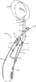
图1是处于头枕的下部初始位置的用于本发明的一个工作例子(工作例子1)的交通工具座椅的座椅靠背结构的竖直横截面图。1 is a vertical cross-sectional view of a seat back structure of a vehicle seat used for one working example (working example 1) of the present invention in a lower initial position of a headrest.
图2是处于头枕的下部初始位置的用于交通工具座椅的座椅靠背结构的部分切除的透视图。2 is a partially cutaway perspective view of a seat back structure for a vehicle seat in a lower initial position of a headrest.
图3是处于头枕的上部改变部分的用于交通工具座椅的座椅靠背结构的竖直横截面图。3 is a vertical cross-sectional view of a seat back structure for a vehicle seat at an upper changing portion of a headrest.
图4(A)(B)分别构成支架导向件的透视图和竖直横截面图。4(A)(B) respectively constitute a perspective view and a vertical cross-sectional view of the bracket guide.
图5是处于头枕的上部改变位置的用于交通工具座椅的座椅靠背结构的部分切除的竖直放大横截面图。5 is a partially cutaway vertical enlarged cross-sectional view of a seat back structure for a vehicle seat in an upper changed position of a headrest.
图6(A)(B)分别是处于头枕的下部初始位置和上部改变位置的用于本发明的另一个工作例子(工作例子2)的交通工具座椅的座椅靠背结构的竖直横截面图。Fig. 6 (A) (B) is the vertical transverse view of the seat back structure of the vehicle seat used in another working example (working example 2) of the present invention in the lower initial position and the upper changed position of the headrest, respectively. Sectional view.
图7是处于头枕的下部初始位置的用于交通工具座椅的座椅靠背结构的部分切除的透视图。7 is a partially cutaway perspective view of the seat back structure for a vehicle seat in the lower initial position of the headrest.
图8(A)至(C)是关于本发明的利用腰部支撑件(lumbar support)作为曲柄构件的一个工作例子(工作例子3)的一组骨架过程图(skeletalprocess figure),其示出了曲柄构件是如何保持的。8(A) to (C) are a set of skeletal process figures (skeletal process figures) of a working example (working example 3) of the present invention utilizing a lumbar support (lumbar support) as a crank member, which shows a crank How components are maintained.
图9是关于本发明的利用腰部支撑件作为曲柄构件的一个工作例子的保持结构(retaining structure)的骨架图。FIG. 9 is a skeleton diagram of a retaining structure of a working example of the present invention utilizing a lumbar support as a crank member.
图10是保持结构的局部视图,其示出了插入孔和近似字母L形的部分之间的关系。Fig. 10 is a partial view of the holding structure showing the relationship between the insertion hole and the approximately L-shaped portion.
图11(A)(B)分别是衬套的主视图和透视图。11(A)(B) are front view and perspective view of the bushing, respectively.
图12是图解了用于交通工具座椅的带有腰部附件的座椅靠背结构的主视图。12 is a front view illustrating a seat back structure with a lumbar attachment for a vehicle seat.
图13是图12的座椅靠背结构的横截面图。FIG. 13 is a cross-sectional view of the seat back structure of FIG. 12 .
图14是图13的座椅靠背结构的截面图的放大的部分。FIG. 14 is an enlarged portion of a cross-sectional view of the seat back structure of FIG. 13 .
图15是沿图12中的A-A线剖切所得的截面图。Fig. 15 is a sectional view taken along line A-A in Fig. 12 .
图16是图12的座椅靠背结构的后透视图。16 is a rear perspective view of the seat back structure of FIG. 12 .
图17是图16的后透视图的放大的部分。FIG. 17 is an enlarged portion of the rear perspective view of FIG. 16 .
图18是用于交通工具座椅的带有腰部附件的座椅靠背结构的一个工作例子(工作例子4)的主视图。Fig. 18 is a front view of a working example (working example 4) of a seat back structure with a lumbar attachment for a vehicle seat.
图19是用于交通工具座椅的带有腰部附件的座椅靠背结构的一个工作例子(工作例子5)的主视图。Fig. 19 is a front view of a working example (working example 5) of a seat back structure with a lumbar attachment for a vehicle seat.
本发明的实施方式的详细描述Detailed Description of Embodiments of the Invention
根据需要,这里公开了本发明的详细实施方式;然而,应理解,所公开的实施方式仅是本发明的示例,而其可实现为不同的以及可选的形式。附图并非一定是按比例绘制的;一些特征可能被夸大或缩小,以显示出特定部件的细节。因此,这里公开的具体的结构和功能细节不应被解释成限制,而是仅仅作为权利要求的代表性基础和/或示教本领域技术人员来多方面地使用本发明的代表性基础。As required, detailed embodiments of the present invention are disclosed herein; however, it is to be understood that the disclosed embodiments are merely exemplary of the invention which may be embodied in different and alternative forms. The figures are not necessarily to scale; some features may be exaggerated or minimized to show details of particular components. Therefore, specific structural and functional details disclosed herein are not to be interpreted as limiting, but merely as a representative basis for the claims and/or as a representative basis for teaching one skilled in the art to variously employ the present invention.
本发明的实施方式是按下述方式构建的:压力接收构件被设计成能够接收来自乘客的骨盆区域和背部部分的载荷的竖直设置的压力接收构件;在后端碰撞发生时,由于由乘客的骨盆区域施加的载荷,压力接收构件在向后方向和上部方向上圆形地移动曲柄构件,且同时在向后方向和上部方向上移动,以圆形地移动圆形移动连杆;因此,在由乘客的骨盆区域施加载荷之后,由乘客的背部部分施加的载荷也被作用于压力接收构件上。Embodiments of the present invention are constructed in the following manner: the pressure receiving member is designed as a vertically disposed pressure receiving member capable of receiving loads from the passenger's pelvic area and back portion; The pressure receiving member circularly moves the crank member in the rearward direction and the upper direction, and simultaneously moves in the rearward direction and the upper direction to circularly move the circular movement link; therefore, After the load is applied by the occupant's pelvic region, the load applied by the occupant's back portion is also acted on the pressure receiving member.
在本发明的至少一个实施方式中,曲柄构件的臂边缘被弯曲成近似字母L的形状,且围绕臂设置的衬套被配合到插入孔中;因此,曲柄构件以圆形移动的方式保持在支撑构件之间。In at least one embodiment of the present invention, the arm edge of the crank member is bent into an approximate shape of a letter L, and a bush provided around the arm is fitted into the insertion hole; thus, the crank member is held in a circular movement. between support members.
工作例子1working example 1
图1和图2分别是处于头枕的下部初始位置的本发明的一个工作例子的座椅靠背结构的竖直横截面图和部分切除的透视图,而图3是处于头枕的上部改变位置的上述的座椅靠背结构的竖直横截面图。Figures 1 and 2 are a vertical cross-sectional view and a partially cut-away perspective view, respectively, of a seat back structure of a working example of the present invention in the lower initial position of the headrest, while Figure 3 is in the upper changed position of the headrest A vertical cross-sectional view of the above-mentioned seat back structure.
如图1和图3所示,座椅靠背10被构建成使得其配备有所谓的紧急启动头枕12。当在发生后端碰撞,头枕12接收了乘客在向后方向上的惯性的转移引起的载荷时,头枕12从图1所示的下部初始位置转变到图3所示的上部改变位置。As shown in FIGS. 1 and 3 , the seat back 10 is constructed such that it is equipped with a so-called
此外,图3用虚线示出了下部初始位置,以及用实线示出了上部改变位置,且头枕12向前倾斜,并如箭头所示按圆弧运动来改变其位置。In addition, FIG. 3 shows the lower initial position with a dotted line and the upper changed position with a solid line, and the
如图1和图3以及图2中清楚地示出的,近似字母L形的一对左圆形移动连杆和右圆形移动连杆14分别被安装成使得能够通过摇摆支撑销(swing-supporting pin)16在,例如,座椅靠背框架18的左侧构件和右侧构件18a上的连杆支架19上摇摆。此外,支撑轴20被设置成横跨着悬挂在对应于左圆形移动连杆和右圆形移动连杆14的边缘上,且被支承为可通过轴进行旋转;因此,支撑轴20被横向设置,以便随着圆形移动连杆圆形地移动而在其上部方向和下部方向上进行圆形地移动。As shown clearly in Fig. 1 and Fig. 3 and Fig. 2, a pair of left circular moving link and right circular moving
此外,在图2中,右圆形移动连杆14在图中藏在右侧构件18a之下。Furthermore, in FIG. 2, the right circular moving
柱状保持器支架24插入到头枕12的支柱22中,并由头枕12的支柱22支撑,且其下边缘固定在支撑轴20上;同时,该支架被设计成穿过设置在座椅靠背框架18的上部构件18b上的支架导向件26,以便与支架导向件接触地自由滑动,且以便自由倾斜。因此,当圆形移动连杆14和支撑轴20圆形地移动时,保持器支架24可向前倾斜,而支架导向件26起到支点的作用;当保持器支架向前倾斜时,头枕12被支撑为使得它可从其下部初始位置转移到其上部改变位置,同时向前倾斜。The
在该工作例子中,当从侧面看柱体的矩形形状的横截面图时,保持器支架24形成为接近日文平假名字母KU(类似字母表字母V向侧面转向成其开口端朝向右)的形状,且头枕的支柱22经由支柱保持器28插入通过保持器支架的上边缘。In this working example, when the cross-sectional view of the rectangular shape of the column is viewed from the side, the
此外,支柱保持器28以固定的方式插入保持器支架24的上半部24a,并在任意的上点和下点通过锁定机构来支撑支柱22。支柱保持器的构造并不是本发明的本质,而为众所周知的构造;因此,省略了其详细说明。In addition, the
如图2中清楚地示出地,保持器支架24的上半部24a插入支架导向件26。As best shown in FIG. 2 , the
图4(A)和(B)分别示出了支架导向件的透视图和竖直横截面图。4(A) and (B) show a perspective view and a vertical cross-sectional view of the bracket guide, respectively.
如图4(A)和(B)所示,支架导向件26配备有前壁28f和后壁28r,且这些壁各自具有第一支撑面28a和第二支撑面28b,其中,该第一支撑面28a的倾斜角度对应于保持器支架在头枕处于下部初始位置时的角度,而该第二支撑面28b的倾斜角度对应于保持器支架在头枕处于上部改变位置的角度。除了上述内容之外,前壁和后壁的第一支撑面28a和第二支撑面28b在不同的高度交替地形成为平行的平面,这能够将保持器支架夹在中间。因此,由于被前壁和后壁夹在中间,保持器支架被支撑在头枕12的下部初始位置和上部改变位置。4 (A) and (B), the
因为支架导向件26被构建成如上所述的壁,如图4(B)所示,因为在头枕的下部初始位置和上部改变位置,保持器支架24可被夹成与支架导向件的前壁和后壁的表面接触,所以,支架导向件26支撑头枕12,从而能够以可靠的方式防止头枕12不稳定。Because the
通过在26的左侧壁和右侧壁上设置形状近似日文片假名KO的槽(类似在水平方向上稍微细长的矩形,且其左侧被切除),向下的钩(downwardhook)26a形成在左侧壁和右侧壁上,且环绕的环向台阶26b在钩的下方形成在支架导向件的周围,以便面向钩。由于上面的设置,通过将座椅靠背框架的18b夹在向下的钩26a和环绕的环向台阶26b之间,使支架导向件26以固定的方式用座椅靠背框架的上部构件锁住。A downward hook (downward hook) 26a is formed by providing a groove (like a slightly elongated rectangle in the horizontal direction with the left side cut off) on the left side wall and the right side wall of 26 in a shape approximate to the Japanese katakana KO On the left and right side walls, and around, a
如上面所说明的,因为支撑轴20以可在上部方向和下部方向上移动的方式支撑在左圆形移动连杆和右圆形移动连杆14上,因此,当支撑轴在上部方向和下部方向上移动,而圆形移动连杆进行圆形移动时,头枕12的位置在其上部位置和其下部位置之间改变。此外,当支撑轴20由于圆形移动连杆的摇摆支撑销16起到支点的作用而在上部方向和下部方向上以圆弧移动的方式移动时,头枕12由于支架导向件26起到支点的作用而向前和向后倾斜(见图1、图3和图4(B))。As explained above, since the
如图2中清楚地示出地,在该工作例子中,止动器19a以大致垂直的方式从连杆支架19弯曲,且突出在圆形移动连杆14的圆形移动路径上。有了上面的设置,由于由止动器19a产生的锁住效应(1atching effect),在头枕12的下部初始位置,圆形移动连杆14的圆形移动得到了控制。As clearly shown in FIG. 2 , in this working example, the
对于圆形移动连杆14,由供能装置30给出供能力,作为在头枕12处于其下部初始位置的方向上时对头枕12供给能量的力。换句话说,头枕12在处于其下部初始位置的方向上时由供能装置30提供的供能力供给能量。For the circular moving
在该工作例子中,供能装置30体现为拉伸螺旋弹簧,其被设置成悬挂在座椅靠背框架的圆形移动连杆14与左侧构件和右侧构件18a上。除了以上内容之外,拉伸螺旋弹簧的上边缘30a锁在圆形移动连杆14的位于支撑轴20上方的锁住孔中,且拉伸螺旋弹簧的下边缘30a锁在座椅靠背框架的左侧构件和右侧构件18a上设置的位于支撑轴20下方的锁住孔中;因此,在头枕的下部初始位置的方向上,供能力被施加到圆形移动连杆14。In this working example, the
换句话说,在图2中,供能力由供能装置30(拉伸螺旋弹簧)施加到圆形移动连杆14,该供能力使圆形移动连杆14绕摇摆支撑销16在顺时针方向上圆形地移动。In other words, in FIG. 2 , the feeding force is applied to the circular moving
配备有这种类型的紧急启动头枕12的座椅靠背结构被构建成使得:在后端碰撞发生时,由于向后方向上的惯性的转移而引起的载荷抵抗供能力(由拉伸螺旋弹簧的弹簧提供的力),从而使圆形移动连杆14圆形地移动到头枕的上部改变位置。换句话说,座椅靠背10被构建成使得:在后端碰撞发生时,由乘客在向后方向上的惯性的转移引起的载荷由预定的压力接收构件接收,且该载荷被传递并施加到圆形移动连杆14,成为在头枕的上部改变位置的方向上的圆形移动力,对抗由供能装置30提供的供能力。The seat back structure equipped with this type of emergency start
在该工作例子中,压力接收构件34能够接收来自乘客的骨盆区域和背部部分的载荷,且其被设置在座椅靠背18内;在该工作例子中,压力接收构件体现为竖直设置的且以一种方式向下延伸的压力接收构件,该方式使得其借助于粘合剂等通过其上边缘固定到支撑轴上。因此,它可响应于支撑轴而移动,且它能够接收来自乘客的骨盆区域和背部部分的载荷。In this working example, the
压力接收构件34优选地,例如用以向下延伸的方式设置的棒状构件形成,或例如用这样一种棒状构件形成:该棒状构件具有在其接收来自乘客的骨盆区域和背部部分的载荷时能够使压力接收构件按压支撑轴20的刚性,以及能够使压力接收构件弯曲的柔性。The
如图2中清楚地示出地,压力接收构件34形成为近似字母U形,如从前面看到的,其具有一对竖直轴34a和水平轴34b,该对竖直轴34a通过弯曲棒构件形成,且具有使压力接收构件能够接收来自乘客的背部部分的载荷的宽度,而该水平轴34b在该对竖直轴34a的下部位置处连接该对竖直轴34a。水平轴34b起到接收来自乘客的骨盆区域的载荷的作用,且设置在某一位置,在该位置,可以接收在后端碰撞发生时,由在向后方向上的惯性的转移引起的来自乘客的骨盆区域的载荷,例如,设置在座椅的侧向的接近中央处,该处以大致相同的距离与座椅靠背框架的左侧构件和右侧构件18a间隔开。As clearly shown in FIG. 2, the
在该工作例子中,因为该对竖直轴34a的下半部34a2的宽度被设计成比上半部34a1的宽度窄,且水平轴34b被设计成比该对竖直轴34a之间的距离窄,因此,来自乘客的骨盆区域的载荷可由水平轴以安全的方式接收。此外,因为压力接收构件34通过弯曲棒状构件而形成,因此,可容易地形成压力接收构件。In this working example, because the width of the lower half 34a2 of the pair of
压力接收构件34与曲柄构件(crank member)36在台阶34a3处连接,该台阶34a3位于34a的下半部,且在该处,该对34a之间的宽度改变。压力接收构件34与曲柄构件36连接,通过用柱状构件35覆盖压力接收构件的台阶34a和曲柄构件36,允许曲柄构件进行圆形移动。The
支撑孔18a1分别形成在座椅靠背框架的左侧构件和右侧构件18a上。通过使曲柄构件36的弯曲的左边缘和右边缘36a以可旋转的方式支撑在该支撑孔中,曲柄构件被设置成横跨着悬挂在座椅靠背框架的左侧构件和右侧构件上,且因此以可进行圆形移动的方式设置在向后方向和上部方向上。Support holes 18a1 are respectively formed on the left and
一般来说,在乘客的正常驾驶姿势下,乘客的骨盆区域大部分与座椅靠背的就座表面接触,而乘客的背部部分倾向于与座椅靠背的就座表面分离。因为上述倾向,当向后方向上的惯性的转移通过后端碰撞而被施加时,乘客的骨盆区域对压力接收构件的水平轴34b的按压的发生早于对压力接收构件的竖直轴34a的按压。Generally, in a normal driving posture of a passenger, most of the pelvic region of the passenger is in contact with the seating surface of the seat back, while a portion of the passenger's back tends to separate from the seating surface of the seat back. Because of the above-mentioned tendency, when the transfer of inertia in the rearward direction is applied by a rear-end collision, pressing of the occupant's pelvic region on the
当发生后端碰撞,乘客的骨盆区域由于向后方向上的惯性的转移而在向后方向上移动,且所产生的压力随后作用在压力接收构件的水平轴34b上时,压力接收构件34在座椅的向后方向上移动,而曲柄构件36进行圆形移动。施加到压力接收构件34的压力作用到压力接收构件的上边缘所固定到的支撑轴20上,使得圆形移动连杆14在图1所示的逆时针方向上圆形地移动。当压力超过由供能装置30提供的供能力时,压力接收构件抬起支撑轴。When a rear-end collision occurs, the occupant's pelvic region moves in the rearward direction due to the transfer of inertia in the rearward direction, and the resulting pressure then acts on the
当压力接收构件抬起支撑轴,抵抗由供能装置30提供的供能力时,圆形移动连杆14开始它们的朝向头枕的上部改变位置的圆形移动。When the pressure-receiving member lifts the support shaft against the energizing force provided by the energizing
如上所说明的,因为圆形移动连杆14由来自乘客的骨盆区域的载荷的输入而启动,因此,当圆形移动连杆启动时,作用在乘客的背部部分上的冲击载荷的影响被降低了。As explained above, since the
此外,尽管在向后方向上的惯性的转移发生时,乘客的骨盆区域对压力接收构件34的移动冲程(shifting stroke)是相对短的,但是,其施加到压力接收构件的压力是足够强大的。因为以上内容,当来自乘客的骨盆区域的载荷的压力被施加时,圆形移动连杆14被平滑地启动,且因此,作用在乘客身上的冲击载荷的影响可被充分地降低。Furthermore, although the shifting stroke of the occupant's pelvic region to the
此外,在圆形移动连杆14启动之后,随着压力接收构件34由于来自乘客的骨盆区域的向后方向上的载荷而移动,圆形移动连杆连续地圆形移动到头枕的上部改变位置;且随着压力接收构件的竖直轴34a由于来自乘客的背部部分的向后方向上的惯性的转移而被按压,压力接收构件在向后方向上移动。因为上述动作,圆形移动连杆14连续地圆形移动到头枕的上部改变位置,而没有被延迟。Further, after the activation of the
换句话说,在圆形移动连杆14启动之后,随着来自乘客的骨盆区域和背部部分的载荷被施加,圆形移动连杆14朝向头枕的上部改变位置的圆形移动继续进行,且头枕由载荷继续保持在上部改变位置。In other words, after the activation of the
因为圆形移动连杆14的圆形移动由来自乘客的骨盆区域的载荷启动,因此,乘客的背部部分按压压力接收构件34时产生的冲击载荷无疑被降低了。同样基于这个观点,圆形移动的启动和圆形移动的继续可以得到确保,而不会迫使乘客经历冲击载荷。Since the circular movement of the circular moving
因为压力接收构件34被构建成接收来自乘客的骨盆区域和背部部分的载荷,因此,即使当来自乘客的骨盆区域的载荷没有以正确的方式施加至压力接收构件34时,来自乘客的背部部分的载荷也会以正确的方式由压力接收构件34接收;因此,引起圆形移动连杆14圆形地移动,且引起头枕12转移至上部改变位置,这进一步提高了头枕将被紧急启动的确定性。Since the
在这点上,如果乘客的背部部分由于向后方向上的惯性的转移,而极大地沉到座椅靠背的就座表面中,由乘客的骨盆区域施加到压力接收构件34的压力可能由于姿势的改变而被降低。In this regard, if the passenger's back portion is greatly sunk into the seating surface of the seat back due to the shift of inertia in the rearward direction, the pressure applied to the
然而,圆形移动连杆14被支撑在头枕的上部改变位置,抵抗由供能装置30提供的供能力,换句话说,当压力接收构件的竖直轴34a由来自乘客的背部部分的载荷按压时,头枕12被支撑在上部改变位置,其中该来自乘客的背部部分的载荷由乘客的背部部分的向后方向上的惯性的转移引起;因此,除了必须依靠来自乘客的骨盆区域的载荷之外,仍可实现将头枕保持在上部改变位置。因此,能够容易地实现初始启动性能和启动维持性能,其中,初始启动性能并不将冲击载荷强迫地施加至乘客,而启动维持性能并不依靠来自乘客的骨盆区域的载荷。However, the circular moving
此外,当发生后端碰撞,压力接收构件接收到来自乘客的骨盆区域和背部部分的载荷时,压力接收构件可在向后方向上移动,这可简单地通过将压力接收构件36连接到可圆形移动的曲柄构件36来实现,而这有助于简化构造。此外,所需的构件仅仅是这两种构件,即,压力接收构件34和曲柄构件36,且这些构件可简单地通过将压力接收构件34连接到可圆形移动的曲柄构件36来装配;该装配不需要高水平的精度,且它可以快速地且容易地进行。此外,压力接收构件34能够根据自由移动而在向后方向上移动,而不需要由配备有导向孔的导向构件来导向或限制;因此,它能够快速地移动,且能够具有高水平的可操作性。Furthermore, when a rear-end collision occurs and the pressure receiving member receives a load from the passenger's pelvic region and back portion, the pressure receiving member can move in the rearward direction simply by connecting the
起到接收来自乘客的骨盆区域和背部部分的载荷的作用的压力接收构件34由具有柔性的棒状构件形成;因此,当施加了来自乘客的骨盆区域和背部部分的载荷时,压力接收构件弯曲,且该弯曲减轻了施加到乘客的骨盆区域和背部部分的冲击载荷。The
顺便提一句,作为回复力,由供能装置30提供的供能力被持续地施加,以便使头枕回到下部初始位置;因此,有必要对头枕12施加超过供能力的力,以便将头枕保持在上部改变位置。Incidentally, as a restoring force, the power supply provided by the
图5是处于头枕的上部改变位置时座椅靠背结构的部分切除的竖直放大横截面图。Fig. 5 is a partially cutaway enlarged vertical cross-sectional view of the seat back structure in the upper changing position of the headrest.
在上部改变位置,扭矩T1(=P1×L1)和扭矩T2(=P2×L2)分别作用在支撑轴上,扭矩T1(=P1×L1)起到使圆形移动连杆14在其操作方向(如图5中所示的逆时针方向)上圆形地移动的作用,且扭矩T2(=P2×L2)起到使圆形移动连杆14回到它们的初始方向(如图5中所示的顺时针方向)的作用。In the upper change position, torque T1 (=P1×L1) and torque T2 (=P2×L2) respectively act on the supporting shaft, and torque T1 (=P1×L1) acts to make the circular moving
P1:由乘客移动至向后方向而引起的操作方向上的载荷。P1: Load in the operating direction caused by the passenger moving to the rearward direction.
L1:摇摆支撑点(摇摆支撑销16)和支撑轴之间在垂直于P1的方向上的距离。L1: distance between the swing support point (swing support pin 16) and the support shaft in a direction perpendicular to P1.
如图5所示,当圆形移动连杆14圆形地移动,以便将头枕12的位置改变至上部改变位置时,L2变得远远小于L1(L2<<L1),且因此,返回方向上的扭矩2变得非常小,如下面所示出的:As shown in FIG. 5, when the circular moving
T2<<T1T2<<T1
换句话说,在头枕的上部改变位置,甚至能够用相对小的力来提供抵抗由供能装置30提供的供能力的抵抗力;因此,如果施加到压力接收构件34的来自乘客的骨盆区域和背部部分的载荷等于预定的值或高于预定的值,则头枕12可保持在上部改变位置。因此,将头枕12安全地保持在上部改变位置,以及获得高水平的保持性能变得可能。In other words, changing the position at the upper part of the headrest can provide resistance against the power supply capacity provided by the
当圆形移动连杆14被进一步圆形地移动且P2的力线超过摇摆支撑销16时,扭矩T2不再起到用于返回方向的扭矩的作用,而变成操作方向的扭矩;因此,头枕12被安全地保持在上部改变位置。When the
此外,在该工作例子中,供能装置以一种方式设置,使得在处于头枕的上部改变位置时,在圆形移动连杆14的摇摆支撑点的附近,由拉伸螺旋弹簧组成的供能装置30的力线位于摇摆支撑点(摇摆支撑16)和支撑轴20之间。当供能装置30根据上述方式设置时,在上部改变位置,传递供能力的效率被有意地降低了;因此,头枕12从上部改变位置的返回启动能(return initiating power)可被安全地降低。Furthermore, in this working example, the energy supply device is arranged in such a way that in the vicinity of the rocking support point of the circular moving
如上所说明的,保持器支架24相对于设置在座椅靠背框架的上部构件18b上的支架导向件26被支撑,以便与支架导向件接触地自由滑动,并且以便自由倾斜。此外,保持器支架24的下边缘固定在支撑轴20上,该支撑轴20被设置成横跨着悬挂在该对左圆形移动连杆和右圆形移动连杆14上,且被设置成可进行旋转。因此,当由后端碰撞所产生的回跳载荷(rebound load)被输入到头枕12中时,该载荷的分力F,如图5中所示,作用在圆形移动连杆的摇摆支撑点(摇摆支撑销16)的上侧。换句话说,上述载荷的分力F将作为将圆形移动连杆14圆形地移动至上部改变位置的力而起作用,以在逆时针方向上在摇摆支撑16附近圆形地移动圆形移动连杆14;因此,头枕12不会由于回跳载荷返回至其下部初始位置。As explained above, the
此外,在压力接收构件34和曲柄构件36的前面板上,还设置了例如,柔性支撑板以及S弹簧,柔性支撑板通过拉伸螺旋弹簧等以柔性方式支撑在座椅靠背框架的左侧构件和右侧构件之间,S弹簧被设置成横跨着悬挂在座椅靠背框架的左侧构件和右侧构件上,为了避免使附图复杂化,它们在图中未示出。支撑板和S弹簧被设置成覆盖它们的前面板,从而在压力接收构件34和曲柄构件36之间留出空间;因为存在该空间,在就座时,压力接收构件不接收由下沉引起的载荷。In addition, on the front panels of the
工作例子2working example 2
图6(A)和图7分别示出了处于头枕的下部初始位置的用于本发明的另一个工作例子(工作例子2)的交通工具座椅的座椅靠背结构的竖直横截面图和部分切除的透视图,而图6(B)示出了其处于头枕的上部改变位置的竖直横截面图。这里,图6(A)、图7和图6(B)分别对应于工作例子1中的图1、图2和图3。6(A) and FIG. 7 are vertical cross-sectional views showing a seat back structure of a vehicle seat for another working example (working example 2) of the present invention in the lower initial position of the headrest, respectively. and a partially cut-away perspective view, while FIG. 6(B) shows a vertical cross-sectional view of it in the upper changed position of the headrest. Here, FIG. 6(A), FIG. 7 and FIG. 6(B) correspond to FIG. 1 , FIG. 2 and FIG. 3 in Working Example 1, respectively.
工作例子2与工作例子1的不同之处仅在于:曲柄构件被设置成横跨着悬挂在一对左支撑连杆和右支撑连杆上,而其余部件与上述工作例子1相同。因此,下面仅说明不同之处。Working Example 2 differs from Working Example 1 only in that the crank member is arranged to be suspended across a pair of left and right support links, and the rest of the components are the same as in Working Example 1 above. Therefore, only the differences are described below.
设置了一对支撑连杆40以便连接曲柄构件36和圆形移动连杆14,以及将曲柄构件的移动传递至圆形移动连杆14。A pair of
如图6(A)(B)和图7中清楚地显示的,例如,该对支撑连杆40通过组合位于上部位置的第一连杆41和位于下部位置的第二连杆42而形成。除了以上内容之外,第一连杆41的上边缘借助于摇摆支撑销41a安装在圆形移动连杆14上,以便能够摇摆,第二连杆42的下边缘借助于摇摆支撑销42a安装在座椅靠背框架的侧构件18a上,以便能够摇摆,且第一连杆和第二连杆的面向边缘借助于摇摆支撑销41b连接在一起,以便能够摇摆。用这种方式,使得支撑连杆40的上边缘(第一连杆41的上边缘)在上部方向和下部方向上是可移动的。As clearly shown in FIGS. 6(A)(B) and 7, for example, the pair of support links 40 is formed by combining a first link 41 at an upper position and a
曲柄构件的边缘36a被安装成能够在形成在第一连杆41上的支撑孔41c上摇摆。导向件41d被设置在第一连杆41上,且曲柄构件的边缘36a由形成在导向件中的导向槽41d1来夹在中间。The
以这种构造,当34由于曲柄构件36在向后方向上的圆形移动而移动时,曲柄构件按压导向件41d,以抬起第一连杆41。由于以上动作,压力(在操作方向上的压力)从支撑连杆40施加至圆形移动连杆,从而起到在如图6(A)所示的逆时针方向(指向头枕的上部改变位置的方向)上,在它们的摇摆支撑点(摇摆支撑销16)附近,抵抗由供能装置30提供的供能力而圆形地移动圆形移动连杆14的作用。With this configuration, when 34 is moved due to the circular movement of the
换句话说,在以上的工作例子1中使用的是由压力接收构件34的向后移动引起的压力,该压力通过支撑轴20使圆形移动连杆14在头枕的上部改变位置的方向上圆形地移动。在该工作例子(工作例子2)中,除了上述的压力之外,曲柄构件36的圆形移动由压力接收构件34的向后移动来产生,且在操作方向上所产生的压力通过支撑连杆40施加至圆形移动连杆。In other words, what is used in the above working example 1 is the pressure caused by the backward movement of the
用这种方式,在由曲柄构件36的圆形移动产生的压力被施加至圆形移动连杆14以更有效地利用曲柄构件36的圆形移动的构造中,可以实现圆形移动连杆的快速的且安全的圆形移动,且圆形移动连杆的启动以及圆形移动的继续可以得到确保,而不会将冲击载荷强施在乘客身上。此外,在应用压力时,可以降低施加到乘客的骨盆区域和背部部分的冲击载荷。In this way, in a configuration in which the pressure generated by the circular movement of the
此外,支撑连杆40不被图中示出的构造所限制,只要它们能够将曲柄构件36的圆形移动施加到圆形移动连杆14,作为操作方向上的压力即可。例如,导向件41d1可采用任何形式,只要它在曲柄构件36的圆形移动被施加时抬起支撑连杆40,并在操作方向上圆形地移动圆形移动连杆14即可。In addition, the support links 40 are not limited by the configuration shown in the drawings as long as they can apply the circular movement of the
根据本发明的至少一个实施方式,在后端碰撞发生时,由于由乘客的骨盆区域施加的载荷,压力接收构件在向后方向和上部方向上圆形地移动曲柄构件,且同时在向后方向和上部方向上移动,以圆形地移动圆形移动连杆;因此,尽管在初始启动时,来自乘客的骨盆区域的载荷被施加到压力接收构件,但在由乘客的骨盆区域施加载荷之后,由乘客的背部部分施加的载荷也被作用于压力接收构件上。因为以上内容,在接收了来自乘客的骨盆区域和背部部分的载荷的情况下,压力接收构件在向后方向和上部方向上移动,以使圆形移动连杆圆形地移动至头枕的上部改变位置,且头枕被平滑地转移至其上部改变位置。然后,通过使压力接收构件接收来自乘客的骨盆区域和背部部分的载荷,使头枕能够继续保持在其上部改变位置。According to at least one embodiment of the present invention, when a rear-end collision occurs, due to the load applied by the passenger's pelvic region, the pressure receiving member circularly moves the crank member in the rearward direction and the upper direction, and at the same time and the upper direction to move the circular moving link circularly; therefore, although the load from the occupant's pelvic area is applied to the pressure receiving member at the initial start-up, after the load is applied by the occupant's pelvic area, The load applied by the passenger's back portion is also acted on the pressure receiving member. Because of the above, in the case of receiving the load from the pelvic area and back portion of the passenger, the pressure receiving member moves in the rearward direction and the upper direction, so that the circular moving link circularly moves to the upper part of the headrest The position is changed, and the headrest is smoothly transferred to its upper changed position. Then, by causing the pressure receiving member to receive the load from the pelvic region and back portion of the passenger, the headrest can be continuously maintained at its upper portion changed position.
除了以上内容之外,因为在初始启动中,压力接收构件是由于施加至其的来自乘客的骨盆区域的载荷而移动的,因此,在初始启动中没有过量载荷施加到乘客的背部部分。In addition to the above, since the pressure receiving member moves due to the load applied thereto from the occupant's pelvic region in the initial actuation, no excessive load is applied to the back portion of the occupant in the initial actuation.
换句话说,根据本发明的至少一个实施方式的构造,能够容易地实现初始启动性能和启动维持性能,其中,初始启动性能并不将冲击载荷强迫地施加至乘客,而启动维持性能并不依靠来自乘客的骨盆区域的载荷。In other words, according to the configuration of at least one embodiment of the present invention, it is possible to easily realize the initial start-up performance which does not forcibly apply a shock load to the passenger and the start-up maintenance performance which does not rely on Loads from the passenger's pelvic area.
此外,在发生后端碰撞,压力接收构件接收了来自乘客的骨盆区域和背部部分的载荷时,压力接收构件可在向后方向上移动,这可简单地通过将压力接收构件连接到可圆形移动的曲柄构件来实现,而这有助于简化构造。此外,所需的构件仅仅是这两种构件,即,压力接收构件和曲柄构件,且这些构件可简单地通过将压力接收构件连接到可圆形移动的曲柄构件来装配;该装配不需要高水平的精度,且它可以快速地且容易地进行。此外,压力接收构件能够根据自由移动而在向后方向上移动,因此,它能够快速地移动,且能够具有高水平的可操作性。In addition, when a rear-end collision occurs and the pressure receiving member receives loads from the pelvic region and back portion of the passenger, the pressure receiving member can move in the rearward direction simply by connecting the pressure receiving member to a circularly movable The crank member is realized, and this helps to simplify the construction. In addition, the required members are only these two members, namely, the pressure receiving member and the crank member, and these members can be assembled simply by connecting the pressure receiving member to the circularly movable crank member; level of precision, and it can be done quickly and easily. In addition, the pressure receiving member can move in the backward direction according to free movement, and therefore, it can move quickly and can have a high level of operability.
工作例子3working example 3
以下是对本发明的至少一个实施方式的说明,其使用附图作为参照。这里,图8(A)至(C)以及图9分别构成:关于本发明的利用腰部支撑件作为曲柄构件的工作例子(工作例子3)的一组骨架过程图,以及保持结构的骨架图,其中该组骨架过程图示出了曲柄构件是如何保持的。The following is a description of at least one embodiment of the invention, using the accompanying drawings by way of reference. Here, FIGS. 8(A) to (C) and FIG. 9 respectively constitute a set of skeleton process diagrams of a working example (working example 3) utilizing a lumbar support as a crank member of the present invention, and a skeleton diagram of a holding structure, Wherein the set of skeleton process diagrams shows how the crank member is held.
在图8和图9中,曲柄构件体现为曲柄形状的腰部支撑件。如图9所示,在支撑就座人员的腰椎的位置,腰部支撑件(曲柄构件)112以圆形移动的方式安装在用于交通工具座椅的座椅靠背框架122的侧框架122L和122R(支撑构件)之间,起到缓解疲劳的作用。本发明的对于腰部支撑件的应用仅仅是一个例子,腰部支撑件本身的构造是众所周知的,且它并不构成本发明的本质;因此,省略了其详细说明。In Figures 8 and 9, the crank member is embodied as a crank-shaped lumbar support. As shown in FIG. 9 , a lumbar support member (crank member) 112 is installed in a circular movement on
腰部支撑件112通过弯曲例如由钢制成的实心棒而形成为曲柄形状,其重复地分别位于左侧和右侧,且它包括水平中心部分112c、位于中心部分112c和左(或右)边缘臂之间的倾斜部分(slope)112b,以及水平臂112a1和112a2。此外,臂112a1和臂112a2的左边缘和右边缘被弯曲成近似字母L的形状。例如,臂112a1和臂112a2的边缘在向下方向上被弯曲大约90°。The
腰部支撑件112通常由贯穿其整个长度具有相同直径的棒材料形成;然而,根据需要,它可由具有不同直径的棒形成。
钥匙孔状的插入孔124始于较大直径孔124a,且连续地延伸至较小直径的长孔124b,该插入孔124形成在支撑构件,即用于交通工具座椅的座椅靠背框架122的侧框架122L和122R中的每一个上。这里,插入孔124的长度形成为使得腰部支撑件的臂的近似字母L形的部分112a’1和112a’2可以在大致水平的方向上插入到插入孔中。换句话说,在图8(A)中,插入孔124的竖直方向上的长度h1大于近似字母L形的部分112a’1的竖直方向上的长度h2;且插入孔的长孔124b的宽度(直径)d1大于臂112a1的直径d2。A keyhole-shaped
图10是保持结构的局部剖视图,其示出了插入孔和近似字母L形的部分之间的关系。Fig. 10 is a partial sectional view of the holding structure showing the relationship between the insertion hole and the approximately L-shaped portion.
如图10所示,插入孔124形成为使得长孔124b在并非与载荷被施加的方向相同的方向上延伸,且长孔124b形成在并非与臂边缘的近似字母L形的部分112a’1的圆形移动范围A重叠的位置。在该工作例子中,长孔124b以大致垂直的方式在上部方向上延伸。As shown in FIG. 10, the
换句话说,在腰部支撑件112中,如箭头所示,载荷F以大致水平的方向从座椅前部作用至座椅后部。然而,因为插入孔的长孔124b并不在大致水平的方向上延伸,因此,臂112a1不会从较大直径孔124a滑开,这使得将臂保持在预定位置成为可能。In other words, in the
只要作为臂112a1的一部分的近似字母L形的部分112a’1,根据腰部支撑件112的圆形移动,也圆形移动至虚线所示的位置,插入孔的长孔124b就不会位于它的圆形移动范围A内。因此,近似字母L形的部分112a’1和长孔124b永远不会排齐,且因此,近似字母L形的部分不会从长孔脱落。As long as the approximately L-shaped portion 112a'1, which is a part of the arm 112a1, is also circularly moved to the position shown by the dotted line in accordance with the circular movement of the
在该工作例子中,插入孔124被构建成使得长孔124b以大致垂直的方式在上部方向上延伸。然而,只要长孔124b在并不与载荷被施加至腰部支撑件的方向相同的方向上延伸,且只要长孔124b不位于与臂边缘的近似字母L形的部分112a’1的圆形移动范围A重叠的位置,就足够了;因此,长孔可延伸的方向并不限制于上部方向。In this working example, the
接下来是关于腰部支撑件的左臂112a1如何通过座椅靠背框架的左侧框架(支撑构件)122L来支撑的说明,其利用图8(A)至(C)作为参照。此外,不用说,腰部支撑件的左臂112a2通过座椅靠背框架的左侧框架(支撑构件)122R来支撑的方式与图8(A)至(C)中所示的相同。Next is a description of how the left arm 112a1 of the lumbar support is supported by the left side frame (support member) 122L of the seat back frame, using FIGS. 8(A) to (C) as a reference. Also, needless to say, the manner in which the left arm 112a2 of the lumbar support is supported by the left side frame (support member) 122R of the seat back frame is the same as that shown in FIGS. 8(A) to (C).
如上所述,近似字母L形的部分112a’1被插入插入孔124,且其通过弯曲腰部支撑件112而形成在腰部支撑件的臂112a1的边缘上。As described above, the approximately letter L-shaped portion 112a'1 is inserted into the
如图9(A)所示,近似字母L形的部分112a’1形成在臂112a1的边缘,并在大致水平的方向上与插入孔124对齐,且近似字母L形的部分112a’1随后被水平地移动,以便如箭头所示被插入到插入孔中。As shown in FIG. 9(A), an approximately letter L-shaped portion 112a'1 is formed on the edge of the arm 112a1, and is aligned with the
其后,如图8(B)中的箭头所示,臂112a1被向下移动以到达插入孔的较大直径孔124a。如图8(C)所示,衬套130围绕位于插入孔的较大直径孔处的臂来设置,使得该臂被支撑在插入孔中。Thereafter, as shown by the arrow in FIG. 8(B), the arm 112a1 is moved downward to reach the larger-
图9(A)(B)分别构成衬套的主视图和透视图。Figure 9(A)(B) respectively constitute the front view and perspective view of the bushing.
如图9(A)(B)所示,衬套130通过使主体130a和凸缘部分130b形成一体而形成,其中该凸缘部分130b的直径大于主体的直径。主体被设计成与插入孔的较大直径孔124a配合在一起。此外,接合件130c形成在主体130a的外周表面上。As shown in FIG. 9(A)(B), the
当衬套的主体130a与插入孔的较大直径孔124a配合时,接合件130c与较大直径孔的周边接合,且起到将侧框架122L夹在接合件和凸缘部分130b之间使得衬套不会脱落的作用。在该工作例子中,两个接合件130c被设置在彼此180°分开的位置。When the
例如,接合件130c被形成为倾斜状形状,其中,高度在接近于凸缘130b的一侧上增加,且留出用于提供槽130c’的空间,在该槽130c’处,侧框架122L被夹在面向凸缘部分的边缘表面和凸缘部分之间,而几乎没有游隙。For example, the engaging
只要衬套130与插入孔的较大直径孔124a配合在一起而衬套不会脱落,接合件130c就足够地起作用了,而不被图中所示的形状所限制。例如,接合件的数量不被限制到2,而它可以是三个或更多。此外,只要接合件130c的形状是具有槽130c’的形式,在该槽130c’处,侧框架122L被夹在面向凸缘部分的边缘表面和凸缘部分之间而几乎没有游隙,则接合件130c就能足够地起作用。除了分段的形状之外,接合件130c可采取具有能够将侧框架夹在中间的圆形槽的截头圆锥的形状。As long as the
然而,当接合件130c被形成为分段的形状,且被设置在衬套的主体130a的周边上的多个分隔开的位置时,如图中所示,衬套的主体变得容易变形;因此,衬套130可与插入孔的较大直径孔124a更平滑地配合在一起。However, when the engaging
在框架122L的外侧,衬套螺母130与来自近似字母L形的部分112a’1的边缘的近似字母L形的部分配合在一起,同时凸缘130b面向外侧;衬套螺母130沿着近似字母L形的部分滑动,直到它到达臂112a1;且然后,形成在主体的周边上的接合件130c被按压成靠着插入孔的较大直径孔124a。然后,主体130a变形,插入较大直径孔124a并与较大直径孔124a配合在一起;接合件130c随后返回它们的原始形状且与较大直径孔的周边紧密配合,从而侧框架122L被夹在凸缘部分130b和接合件之间的槽130c’中。On the outer side of the
类似地,座椅靠背框架的右侧框架122R也通过衬套130被夹在中间。Similarly, the
通过使左侧框架122L和右侧框架122R由配合在插入孔的较大直径孔124a内的衬套130而被夹在中间,腰部支撑件的左臂112a1和右臂112a2以自由地圆形移动的方式由插入孔124来支撑,且腰部支撑件112(曲柄构件)以自由地圆形移动的方式由左侧框架和右侧框架(支撑构件)来支撑。By making the
此外,当腰部支撑件的臂112a1和112a2的边缘被弯曲成近似字母L的形状时,形成近似字母L形的部分112a’1和112a’2。因此,对于臂边缘,提供诸如台阶成型工艺或圆形槽成型工艺的特殊工艺变得不必要,这使得降低成本成为可能。In addition, when the edges of the arms 112a1 and 112a2 of the lumbar support are bent into an approximate shape of a letter L, approximately L-shaped portions 112a'1 and 112a'2 are formed. Therefore, for the arm edge, it becomes unnecessary to provide a special process such as a step forming process or a circular groove forming process, which makes it possible to reduce the cost.
此外,甚至当过量载荷被施加至腰部支撑件112时,臂边缘上的被插入到侧框架的插入孔124中的近似字母L形的部分112a’1和112a’2也被支撑构件的插入孔锁住且能够抵抗载荷。因此,甚至当衬套130被损坏时,臂也不会从插入孔脱落。换句话说,尽管该构造简单得以至于通过弯曲臂112a1和112a2的边缘就能够简单地实现,但是,该保持结构仍能够抵抗载荷,并完全防止臂从插入孔124脱落。In addition, even when an excessive load is applied to the
因为围绕腰部支撑件的左臂112a1和右臂112a2的衬套130与插入孔的较大直径孔124a配合在一起,因此,防止了位于较大直径孔内的近似字母L形的部分在长孔方向上的移动。因此,在没有过量载荷被施加的正常使用的情况下,臂112a1和112a2不会从插入孔124脱落。Because the
甚至当腰部支撑件的左臂112a1和右臂112a2的边缘被形成为近似字母L的形状时,因为其中插入了近似字母L形的部分112a’1和112a’2的插入孔124被设置在侧框架122L和122R上,所以插入操作可平滑地进行。此外,通过简单地安装衬套130,臂112a1和112a2以自由地圆形移动的方式由插入孔124来支撑,且因此,衬套可被容易地安装。因此,需要特殊工具的任何操作变得不必要,这增加了可操作性。Even when the edges of the left arm 112a1 and the right arm 112a2 of the lumbar support are formed in an approximate letter L shape, since the insertion holes 124 into which the approximately letter L-shaped parts 112a'1 and 112a'2 are inserted are provided on the
衬套130可由金属、硬橡胶、塑料,或其他材料形成。然而,当使用由硬橡胶或塑料形成的衬套130时,它具有适当程度的柔性;因此,在维持平滑的圆形移动的同时,提供支撑作用而不发出声响或噪音变得可能。Bushing 130 may be formed from metal, hard rubber, plastic, or other materials. However, when the
当衬套130被设计成构成带有隙缝的拼合衬套时,衬套130可被安装成不由近似字母L形的部分112a’1和112a’2的边缘来配合,而是由近似字母L形的部分或臂112a1和112a2上的适当位置来配合,这进一步增加了可操作性。When the
工作例子4Working Example 4
图12-17图解了工作例子4,其是工作例子1的进一步的发展。图12和图13图解了带有腰部附件200的座椅靠背10。腰部附件200被连接到压力接收构件34,以便对乘员提供腰部支撑,且以便对紧急启动头枕12提供目标。腰部附件200具有如图12所示的大致矩形的周边,同时具有如图13所示的大致波状外形的座椅靠背轮廓(generally contoured seatback profile)。腰部附件200由网格状图案的支撑构件形成,该网格状图案的支撑构件形成其间具有一系列桁架的行和列。在碰撞环境期间,桁架聚集在与输入力相关联的下部区域中。腰部附件200可由高强度的塑料或类似物形成。12-17 illustrate Working Example 4, which is a further development of Working Example 1. FIG. 12 and 13 illustrate the seat back 10 with the
一对拉伸螺旋弹簧202被各自安装到腰部附件200的上部横向侧面,且被安装到侧构件18a中的一个,以便支撑腰部附件200的上部区域,同时对腰部附件200的上部部分的位置提供顺应性。A pair of tension coil springs 202 are mounted to the upper lateral sides of the
参照图14-17,腰部附件200的下部部分包括一对保持钩204,以便连接到压力接收构件34的下部水平轴34b。在装配期间,保持钩204的倾斜边缘被按压成靠着水平轴34b,使得钩204变形,直到水平轴34b被保持成靠着保持钩204的邻接边缘(abutment edge)。如图17所示,腰部附件200还设置有一对横向间隔开的肋206,其中每个横向间隔开的肋206设置在压力接收构件34的竖直轴34a的下半部34a2的相对的横向侧面上。肋206提供了对于腰部附件200相对于压力接收构件34的横向移动的控制。Referring to FIGS. 14-17 , the lower portion of the
作为乘员被加速进入座椅靠背10的结果,腰部附件200接收输入力,且将输入力传递至压力接收构件34的水平轴34b,以便如以上参照工作例子1所说明地致动紧急启动头枕12。As a result of the occupant being accelerated into the seat back 10, the
工作例子5Working Example 5
在图18中,工作例子5图解了工作例子4的座椅靠背10和腰部附件200。此外,一对连杆208被连接到腰部附件200的下部区域且被连接到座椅靠背10的侧构件18a。连杆208对腰部附件200的下部区域相对于座椅靠背10的移动提供限制。该连杆可由金属丝或任何合适的材料形成。In FIG. 18 , Working Example 5 illustrates the seat back 10 and the
工作例子6Working Example 6
图19图解了工作例子6,该工作例子6为工作例子4的变型。座椅靠背10被图解为带有腰部附件200。一对拉伸螺旋弹簧210被添加到腰部附件200的下部部分,且均从横向侧面延伸,且被连接到座椅靠背10的侧构件18a中的一个。弹簧210对腰部附件200的下部部分提供了顺应性,且用于在其上不存在力的情况下使腰部附件200返回到设计位置。FIG. 19 illustrates Working Example 6, which is a modification of Working Example 4. FIG. Seat back 10 is illustrated with
不用说,以上工作例子仅仅用于说明本发明,而不以任何方式限制本发明;对本发明在其技术范围内的任何变型和更改都包含在本发明的实施方式中。Needless to say, the above working examples are only for illustrating the present invention, but not limiting the present invention in any way; any variations and modifications to the present invention within the technical scope thereof are included in the embodiments of the present invention.
工业适用性Industrial applicability
一般来说,本发明适用于可自由地安装或从座椅靠背移除的头枕。然而,本发明的适用性不限于以上用途。本发明还可适用于不能自由地安装或从座椅靠背移除的头枕。In general, the present invention is applicable to head restraints that can be freely installed or removed from the seat back. However, the applicability of the present invention is not limited to the above uses. The present invention is also applicable to head restraints that cannot be freely installed or removed from the seat back.
在工作例子3中,尽管关于用于交通工具座椅的腰部支撑件是曲柄构件的情况,提供了说明,但是本发明的适用性不限于这种情况。本发明可广泛地适用于以自由地圆形移动的方式安装在支撑构件上的曲柄构件的保持结构。例如,本发明可适用于(用于交通工具座椅的启动头枕的)曲柄状压力接收构件的保持结构,其中当发生后端碰撞,接收到来自就座人员的载荷时,该曲柄状压力接收构件使头枕在上部方向和向前方向上强迫地倾斜。In Working Example 3, although the description was given regarding the case where the lumbar support for the vehicle seat is the crank member, the applicability of the present invention is not limited to this case. The present invention is widely applicable to a holding structure of a crank member mounted on a support member in a freely circularly movable manner. For example, the present invention is applicable to a retaining structure of a crank-shaped pressure receiving member (for an actuating headrest of a vehicle seat), wherein the crank-shaped pressure receives a load from a seated person when a rear-end collision occurs. The receiving member forcibly tilts the headrest in an upper direction and a forward direction.
参考数字的说明Explanation of Reference Numbers
10:座椅靠背10: Seat back
12:头枕12: headrest
14:圆形移动连杆14: Circular moving link
16:摇摆支撑销(用于圆形移动连杆的摇摆支撑点)16: Swing support pin (swing support point for circular moving link)
20:支撑轴20: Support shaft
24:保持器支架24: Retainer bracket
26:支架导向件26: Bracket guide
28f、28r:前壁和后壁28f, 28r: front and rear walls
28a、28b:第一支撑面和第二支撑面28a, 28b: first support surface and second support surface
30:供能装置30: Energy supply device
34:压力接收构件34: Pressure receiving member
34a:竖直轴34a: Vertical axis
34b:水平轴34b: Horizontal axis
112:腰部支撑件(曲柄构件)112: Lumbar support (crank member)
112a1、112a2:臂112a1, 112a2: arm
112a’1、112a’2:近似字母L形的部分112a'1, 112a'2: Approximate letter L-shaped part
122:座椅靠背框架122: Seat Back Frame
122L、122R:侧框架(支撑构件)122L, 122R: side frame (support member)
124:插入孔124: Insertion hole
124a:较大直径孔124a: Larger diameter hole
124b:较小直径的长孔124b: Slotted hole with smaller diameter
130:衬套130: Bushing
130a:主体130a: subject
130b:凸缘部分130b: Flange part
130c:接合件130c: Joint
200:腰部附件200: waist attachment
202:螺旋弹簧202: coil spring
204:保持钩204: Keep the Hook
206:肋206: Rib
208:连杆208: connecting rod
210:螺旋弹簧210: coil spring
1.任务1. Task
本发明的任务是实现初始启动性能和启动维持性能,而不使结构复杂化,其中,初始启动性能并不将冲击载荷强迫地施加至乘客,而启动维持性能并不依靠来自乘客的骨盆区域的载荷。The task of the present invention is to achieve an initial start-up performance which does not forcibly apply shock loads to the occupant and a start-up maintenance performance which does not rely on pressure from the occupant's pelvic region without complicating the structure. load.
2.用于实现任务的手段2. The means used to accomplish the task
被设计成能够接收来自乘客的骨盆区域和背部部分的载荷的压力接收构件34被设置在座椅靠背内部。压力接收构件34形成为从前面看近似字母U的形状,这使得压力接收构件能够接收来自乘客的背部部分的载荷和来自乘客的骨盆区域的载荷。压力接收构件34被连接到曲柄构件36,该曲柄构件36被设置成横跨着悬挂在左侧构件和右侧构件18a上。在后端碰撞发生时,由于由乘客的骨盆区域施加的载荷,压力接收构件在向后方向和上部方向上圆形地移动曲柄构件36,且同时移动至向后方向和上部方向,以抵抗由拉伸弹簧30提供的供能力,来圆形地移动圆形移动连杆;因此,在由乘客的骨盆区域施加载荷之后,由乘客的背部部分施加的载荷也被作用于压力接收构件上,以继续圆形地移动圆形移动连杆。A
3.问题3. Questions
在使用衬套螺母和E环来防止臂脱落的构造中,需要特殊的工艺以及特殊的工具,其中特殊的工艺与用于形成曲柄构件的工艺不同。In constructions where bushing nuts and E-rings are used to prevent the arms from falling out, special processes are required, as well as special tools, which are different from those used to form the crank member.
4.用于解决问题的手段4. Means used to solve problems
腰部支撑件(曲柄构件)的臂112a1的边缘被弯曲以形成近似字母L形的部分112a’1,且近似字母L形的部分被插入到形成在侧框架(支撑构件)122L上的插入孔124中。插入孔124采取钥匙孔状的形状,且其始于较大直径孔并连续地延伸至较小直径的长孔,该插入孔124形成为某一长度,以使得近似字母L形的部分可以在水平的方向上被插入到插入孔中。在近似字母L形的部分112a’1被插入穿过插入孔124之后,带有凸缘的衬套130被围绕臂112a1安装通过近似字母L形的部分,并与插入孔的较大直径孔124a配合在一起。因此,腰部支撑件的臂以圆形移动的方式被支撑在侧框架的插入孔内。The edge of the arm 112a1 of the lumbar support (crank member) is bent to form an approximately L-shaped portion 112a'1, and the approximately L-shaped portion is inserted into an
虽然已经图解和描述了本发明的实施方式,但是并不意味着这些实施方式图解和描述了本发明的所有可能的形式。而是,在本说明书中使用的词汇是描述性的词汇而非限制性的词汇,且应理解,在不背离本发明的精神和范围的情况下可以做出各种改变。While embodiments of the invention have been illustrated and described, it is not intended that these embodiments illustrate and describe all possible forms of the invention. Rather, the words used in the specification are words of description rather than limitation, and it is understood that various changes may be made without departing from the spirit and scope of the invention.
Claims (20)
Applications Claiming Priority (7)
| Application Number | Priority Date | Filing Date | Title |
|---|---|---|---|
| JP2007-198558 | 2007-07-31 | ||
| JP2007198558 | 2007-07-31 | ||
| JP2007211334A JP4667431B2 (en) | 2007-08-14 | 2007-08-14 | Crank member holding structure for vehicle seat |
| JP2007-211334 | 2007-08-14 | ||
| US4171508P | 2008-04-02 | 2008-04-02 | |
| US61/041,715 | 2008-04-02 | ||
| PCT/US2008/071456 WO2009018266A1 (en) | 2007-07-31 | 2008-07-29 | Seat back structure of vehicle seats and retaining structure for a crank member |
Publications (1)
| Publication Number | Publication Date |
|---|---|
| CN101784416A true CN101784416A (en) | 2010-07-21 |
Family
ID=40304807
Family Applications (1)
| Application Number | Title | Priority Date | Filing Date |
|---|---|---|---|
| CN200880101184A Pending CN101784416A (en) | 2007-07-31 | 2008-07-29 | Seat back structure of vehicle seats and retaining structure for a crank member |
Country Status (3)
| Country | Link |
|---|---|
| CN (1) | CN101784416A (en) |
| DE (1) | DE112008001946T5 (en) |
| WO (1) | WO2009018266A1 (en) |
Cited By (7)
| Publication number | Priority date | Publication date | Assignee | Title |
|---|---|---|---|---|
| CN102205808A (en) * | 2011-01-21 | 2011-10-05 | 浙江吉利汽车研究院有限公司 | Backrest framework of vehicle seat |
| CN102529775A (en) * | 2010-12-29 | 2012-07-04 | 株式会社塔捷斯 | Seat back structure of vehicle seat and method for inhibiting head tremor damage for seat back of vehicle seat |
| CN103269904A (en) * | 2010-12-24 | 2013-08-28 | 提爱思科技股份有限公司 | Vehicle seat |
| CN104039648A (en) * | 2012-01-05 | 2014-09-10 | B/E航空公司 | Adjustable headrest for an aircraft seat |
| CN104219980A (en) * | 2012-03-15 | 2014-12-17 | 提爱思科技股份有限公司 | vehicle seat |
| CN108143159A (en) * | 2018-02-07 | 2018-06-12 | 深圳市华仕杰家居用品有限公司 | Chair back waist support linkage mechanism |
| WO2023141742A1 (en) * | 2022-01-25 | 2023-08-03 | Cushy Holdings, Inc | Headrest for furniture |
Families Citing this family (3)
| Publication number | Priority date | Publication date | Assignee | Title |
|---|---|---|---|---|
| DE102009049946B4 (en) * | 2009-09-16 | 2015-04-02 | Johnson Controls Gmbh | Headrest adjustable in X direction |
| DE102012111888A1 (en) * | 2012-12-06 | 2014-06-12 | Recaro Aircraft Seating Gmbh & Co. Kg | Seat component of vehicle seat e.g. aircraft seat has transmission unit that translates force component in direction of bearing surface corresponding to movement of seat unit towards motion resistant direction |
| CN106494280B (en) * | 2016-11-09 | 2018-10-26 | 合肥江瑞汽车零部件有限公司 | Automotive seat and automobile |
Family Cites Families (6)
| Publication number | Priority date | Publication date | Assignee | Title |
|---|---|---|---|---|
| SE510735C2 (en) * | 1996-09-06 | 1999-06-21 | Saab Automobile | Vehicle seat equipped with a headrest |
| US6368563B1 (en) * | 1999-03-12 | 2002-04-09 | Integ, Inc. | Collection well for body fluid tester |
| US6767064B2 (en) * | 2002-02-27 | 2004-07-27 | Lear Corporation | Translatable head restraint for automotive seat backrest |
| US7644987B2 (en) * | 2004-09-27 | 2010-01-12 | Lear Corporation | Vehicle seat having active head restraint system |
| JP2007198558A (en) | 2006-01-30 | 2007-08-09 | Maruyama Machinery Co Ltd | Electromagnetic brake device |
| JP4518029B2 (en) | 2006-02-13 | 2010-08-04 | 住友金属工業株式会社 | High-tensile hot-rolled steel sheet and manufacturing method thereof |
-
2008
- 2008-07-29 CN CN200880101184A patent/CN101784416A/en active Pending
- 2008-07-29 DE DE112008001946T patent/DE112008001946T5/en not_active Withdrawn
- 2008-07-29 WO PCT/US2008/071456 patent/WO2009018266A1/en not_active Ceased
Cited By (13)
| Publication number | Priority date | Publication date | Assignee | Title |
|---|---|---|---|---|
| CN103269904A (en) * | 2010-12-24 | 2013-08-28 | 提爱思科技股份有限公司 | Vehicle seat |
| CN103269904B (en) * | 2010-12-24 | 2016-01-06 | 提爱思科技股份有限公司 | Seat |
| CN102529775B (en) * | 2010-12-29 | 2015-07-22 | 株式会社塔捷斯 | Seat back structure of vehicle seat and method for inhibiting head tremor damage for seat back of vehicle seat |
| CN102529775A (en) * | 2010-12-29 | 2012-07-04 | 株式会社塔捷斯 | Seat back structure of vehicle seat and method for inhibiting head tremor damage for seat back of vehicle seat |
| CN102205808B (en) * | 2011-01-21 | 2012-11-28 | 浙江吉利汽车研究院有限公司 | Backrest framework of vehicle seat |
| CN102205808A (en) * | 2011-01-21 | 2011-10-05 | 浙江吉利汽车研究院有限公司 | Backrest framework of vehicle seat |
| CN104039648A (en) * | 2012-01-05 | 2014-09-10 | B/E航空公司 | Adjustable headrest for an aircraft seat |
| CN104039648B (en) * | 2012-01-05 | 2016-01-13 | B/E航空公司 | For the headrest adjustable of aircraft seat |
| CN104219980A (en) * | 2012-03-15 | 2014-12-17 | 提爱思科技股份有限公司 | vehicle seat |
| CN104219980B (en) * | 2012-03-15 | 2017-03-15 | 提爱思科技股份有限公司 | Vehicle seat |
| CN108143159A (en) * | 2018-02-07 | 2018-06-12 | 深圳市华仕杰家居用品有限公司 | Chair back waist support linkage mechanism |
| CN108143159B (en) * | 2018-02-07 | 2023-08-29 | 深圳市华仕杰家居用品有限公司 | Chair back lumbar linkage mechanism |
| WO2023141742A1 (en) * | 2022-01-25 | 2023-08-03 | Cushy Holdings, Inc | Headrest for furniture |
Also Published As
| Publication number | Publication date |
|---|---|
| WO2009018266A1 (en) | 2009-02-05 |
| DE112008001946T5 (en) | 2010-06-02 |
Similar Documents
| Publication | Publication Date | Title |
|---|---|---|
| CN101784416A (en) | Seat back structure of vehicle seats and retaining structure for a crank member | |
| US8590979B2 (en) | Seatback device | |
| JP4737501B2 (en) | Vehicle seat | |
| US7540562B2 (en) | Seat back structure of vehicle seat | |
| JP5308011B2 (en) | Vehicle seat | |
| US6866339B2 (en) | Head rest apparatus | |
| EP1382481B1 (en) | Vehicular seat including forward movable headrest | |
| US7758114B2 (en) | Seat back structure of vehicle seat | |
| JP6004909B2 (en) | Vehicle seat | |
| JP5091574B2 (en) | Vehicle seat | |
| EP2039562A1 (en) | Vehicle seat | |
| US20140354025A1 (en) | Vehicle seat | |
| JP5030281B2 (en) | Seat back structure for vehicle seat | |
| JP2010522111A (en) | Backrest support mechanism | |
| CN102529775B (en) | Seat back structure of vehicle seat and method for inhibiting head tremor damage for seat back of vehicle seat | |
| GB2403137A (en) | A vehicle seat | |
| JP4327708B2 (en) | Vehicle seat | |
| JP3740933B2 (en) | Vehicle seat | |
| JP2019107981A (en) | Vehicle seat | |
| JP5252936B2 (en) | Vehicle seat | |
| JP6565311B2 (en) | Vehicle seat | |
| JP2015020703A (en) | Vehicle seat | |
| JP2012091565A (en) | Vehicle seat | |
| KR101554745B1 (en) | Vehicle seat | |
| JP6322501B2 (en) | Vehicle seat |
Legal Events
| Date | Code | Title | Description |
|---|---|---|---|
| C06 | Publication | ||
| PB01 | Publication | ||
| C10 | Entry into substantive examination | ||
| SE01 | Entry into force of request for substantive examination | ||
| C02 | Deemed withdrawal of patent application after publication (patent law 2001) | ||
| WD01 | Invention patent application deemed withdrawn after publication |
Application publication date: 20100721 |