CN101770650B - Three-dimensional ultrasound real-time imaging method and device and imaging system - Google Patents
Three-dimensional ultrasound real-time imaging method and device and imaging system Download PDFInfo
- Publication number
- CN101770650B CN101770650B CN 200910104840 CN200910104840A CN101770650B CN 101770650 B CN101770650 B CN 101770650B CN 200910104840 CN200910104840 CN 200910104840 CN 200910104840 A CN200910104840 A CN 200910104840A CN 101770650 B CN101770650 B CN 101770650B
- Authority
- CN
- China
- Prior art keywords
- reconstructed
- volume data
- equations
- equation
- acquisition
- Prior art date
- Legal status (The legal status is an assumption and is not a legal conclusion. Google has not performed a legal analysis and makes no representation as to the accuracy of the status listed.)
- Active
Links
Images


Landscapes
- Ultra Sonic Daignosis Equipment (AREA)
Abstract
Description
技术领域 technical field
本发明涉及一种成像方法与装置,特别是涉及一种三维超声实时成像方法与装置,以及包含该装置的超声成像系统。The invention relates to an imaging method and device, in particular to a three-dimensional ultrasonic real-time imaging method and device, and an ultrasonic imaging system including the device.
背景技术 Background technique
传统医疗影像设备仅仅提供人体内部的二维图像,医生只能凭经验由多幅二维图像去估计病灶的大小及形状,以此想像病灶与其周围组织的三维几何关系,这给治疗带来了困难。而三维可视化技术可以由一系列二维图像重构出三维形体,并在终端显示出来。因此不仅能得到有关成像物体直观、形象的整体概念,而且还可保存许多重要的三维信息。另外,由于超声成像较CT和MRI具有无创、无电离辐射以及操作灵活等明显优势,所以超声三维成像势必会在医学临床上得到广泛的应用,开展超声领域中的三维可视化研究显得十分必要。Traditional medical imaging equipment only provides two-dimensional images of the inside of the human body. Doctors can only estimate the size and shape of the lesion from multiple two-dimensional images based on experience, so as to imagine the three-dimensional geometric relationship between the lesion and its surrounding tissues, which brings great benefits to the treatment. difficulty. The 3D visualization technology can reconstruct a 3D shape from a series of 2D images and display it on the terminal. Therefore, not only can the overall concept of the intuitive and image of the imaging object be obtained, but also a lot of important three-dimensional information can be preserved. In addition, because ultrasound imaging has obvious advantages such as non-invasiveness, no ionizing radiation, and flexible operation compared with CT and MRI, three-dimensional ultrasound imaging is bound to be widely used in clinical medicine, and it is very necessary to carry out three-dimensional visualization research in the field of ultrasound.
按照一种现有的加快三维超声成像速度的方法,在已知原始体数据和采集姿态参数的基础上,得到一个虚拟的重构体数据。为了将重构体数据的直角坐标映射为原始体数据的极坐标,需要建立一个查找表,称为“重构变换表”。该表的每个元素对应重构体数据的一个体素,除了记录当前体素的坐标变换结果,还需要记录当前体素是否位于重构六面体内。若当前体素完全位于重构六面体之内,则称为“有效体素”;若当前体素完全位于重构六面体之外,即残余空间以内,则称为“无效体素”;若当前体素位于重构六面体和残余空间的交界之处,则称为“临界体素”。According to an existing method for accelerating the speed of three-dimensional ultrasonic imaging, a virtual reconstructed volume data is obtained on the basis of known original volume data and collected attitude parameters. In order to map the Cartesian coordinates of the reconstructed volume data to the polar coordinates of the original volume data, a look-up table, called "reconstruction transformation table", needs to be established. Each element of this table corresponds to a voxel of the reconstructed volume data. In addition to recording the coordinate transformation result of the current voxel, it is also necessary to record whether the current voxel is located in the reconstructed hexahedron. If the current voxel is completely within the reconstructed hexahedron, it is called "valid voxel"; if the current voxel is completely outside the reconstructed hexahedron, that is, within the residual space, it is called "invalid voxel"; if the current voxel If the voxel is located at the junction of the reconstructed hexahedron and the residual space, it is called a "critical voxel".
重构变换表用于体绘制,这里的绘制方法仍然是基于光线投射算法的。从视平面的当前像素发射出一条光线,首先利用重构包围盒的边界将其裁剪为线段,称为“盒内线段”。然后从盒内线段的起点开始,以一定步长沿光线方向行进,得到一系列采样点。将当前采样点的坐标取整,得到当前体素,然后查询重构变换表:若当前体素是无效体素,则当前采样点一定位于残余空间;若当前体素是有效体素,则当前采样点一定位于重构六面体内;若当前体素是临界体素,则当前采样点所位于的区间未定,需要补充进行一次双线性插值(Bilinear Interpolation)运算,才能决定该采样点是位于重构六面体内还是残余空间内。经过上述判断之后,若当前采样点位于残余空间内,则略过该采样点;若当前采样点位于重构六面体内,则需根据当前采样点坐标的小数部分,以及当前体素的坐标变换结果,进行一次三线性插值(Trilinear Interpolation)运算,得到当前采样点的灰度值,并以此进行光线合成。一旦得到第一个位于重构六面体内的采样点,则不再判断后续的采样点,而一律以重构六面体内情况下的方法进行插值和合成。如此逐步行进,直到采样点抵达盒内线段终点,或者累计的不透明度值达到给定的阈值为止,后者称为“光线中止”。然而,该现有技术存在有以下几个缺点:The reconstruction transformation table is used for volume rendering, and the rendering method here is still based on the ray casting algorithm. A ray is fired from the current pixel in the view plane, which is first clipped to a line segment using the bounds of the reconstructed bounding box, called a "line segment within the box". Then, starting from the starting point of the line segment in the box, proceed along the light direction with a certain step size, and obtain a series of sampling points. Round the coordinates of the current sampling point to obtain the current voxel, and then query the reconstruction transformation table: if the current voxel is an invalid voxel, the current sampling point must be located in the residual space; if the current voxel is a valid voxel, the current voxel The sampling point must be located in the reconstructed hexahedron; if the current voxel is a critical voxel, the interval where the current sampling point is located is undetermined, and a bilinear interpolation (Bilinear Interpolation) operation is required to determine whether the sampling point is located in a reconfigured hexahedron. In the hexahedron or in the residual space. After the above judgment, if the current sampling point is located in the residual space, skip the sampling point; if the current sampling point is located in the reconstructed hexahedron, it needs to transform the coordinates of the current sampling point according to the fractional part of the coordinates of the current sampling point and the coordinate transformation result of the current voxel. , perform a Trilinear Interpolation (Trilinear Interpolation) operation to obtain the gray value of the current sampling point, and use this to perform light synthesis. Once the first sampling point located in the reconstructed hexahedron is obtained, the subsequent sampling points are no longer judged, but are all interpolated and synthesized in the same way as in the reconstructed hexahedron. This step by step is carried out until the sampling point reaches the end point of the line segment in the box, or the accumulated opacity value reaches a given threshold, the latter is called "ray stop". However, this prior art has the following disadvantages:
1.采样点首次进入重构六面体之前,需要逐一判断采样点是否位于重构六面体内,导致效率较低。尤其当采样点取整得到的体素为临界体素时,判断方法比较复杂,严重影响了成像速度;1. Before the sampling point enters the reconstructed hexahedron for the first time, it is necessary to judge whether the sampling point is located in the reconstructed hexahedron one by one, resulting in low efficiency. Especially when the voxel obtained by rounding the sampling point is a critical voxel, the judgment method is more complicated, which seriously affects the imaging speed;
2.一旦得到第一个位于重构六面体内的采样点,则后续的采样点一律以重构六面体内情况下的方法进行插值和合成。但是,这种处理方法是不妥的,因为在很多情况下,后续采样点可能未达到光线中止条件时就穿出了重构六面体,若还按照重构六面体内情况下的方法进行插值和合成,即使不会导致计算出错,也将带来无谓的计算开销,影响了成像速度;2. Once the first sampling point located in the reconstructed hexahedron is obtained, the subsequent sampling points will be interpolated and synthesized in the same way as in the reconstructed hexahedron. However, this approach is inappropriate, because in many cases, subsequent sampling points may pass through the reconstructed hexahedron before reaching the ray termination condition. , even if it does not cause calculation errors, it will bring unnecessary calculation overhead and affect the imaging speed;
3.因为采样点是以一定步长行进的,因此第一个位于重构六面体内的采样点往往不是位于重构六面体的表面,而是已经穿入表面一定深度(在此称为“误差深度”)。每条光线的误差深度可能各不相同,虽然该深度总是小于光线步长,但其仍会对该光线的合成结果产生一定影响。随着光线的空间分布,误差深度表现出一定的周期性,导致成像结果出现环状、网状、锯齿状等特定形状的纹理,即产生了走样(Aliasing)现象,严重影响了成像质量。若通过设置较小的光线步长,可以缓解误差深度导致的走样现象,但很难完全消除,而且将导致成像速度的进一步下降;3. Because the sampling point travels with a certain step length, the first sampling point located in the reconstructed hexahedron is often not located on the surface of the reconstructed hexahedron, but has penetrated into the surface to a certain depth (herein referred to as "error depth "). The depth of error can vary for each ray, and while the depth is always smaller than the ray step size, it still has some influence on the composite result for that ray. With the spatial distribution of light, the error depth shows a certain periodicity, resulting in ring, mesh, jagged and other specific shapes of texture in the imaging result, that is, the phenomenon of aliasing (Aliasing) occurs, which seriously affects the imaging quality. By setting a smaller ray step size, the aliasing phenomenon caused by the error depth can be alleviated, but it is difficult to completely eliminate it, and it will lead to a further decrease in imaging speed;
4.为了标记采样点是否在重构六面体内,重构变换表内需要计算几个专门的字段,而且该表在整个成像过程中需要一直保持,增加了处理的时间和空间开销;4. In order to mark whether the sampling point is in the reconstruction hexahedron, several special fields need to be calculated in the reconstruction transformation table, and the table needs to be kept throughout the imaging process, which increases the processing time and space overhead;
5.三维超声至少有四种采集模式,而该现有技术只给出了凸阵扇扫采集模式下的方法。5. There are at least four acquisition modes for 3D ultrasound, but this prior art only provides a method in the convex array sector scan acquisition mode.
发明内容 Contents of the invention
本发明的目的是为了克服现有技术存在的缺陷,提供一种三维超声实时成像方法与装置。为了实现这一目的,本发明所采取的技术方案如下。The object of the present invention is to provide a three-dimensional ultrasonic real-time imaging method and device in order to overcome the defects in the prior art. In order to realize this object, the technical scheme that the present invention takes is as follows.
按照本发明实施例的第一方面,提供一种用于超声成像的重构方法,包括生成步骤,用于从原始体数据生成重构体数据;还包括:构造步骤,根据采集模式确定重构多面体的各面形状,并根据采集姿态参数确定出重构多面体各面的曲面方程,由曲面的交割构成重构多面体;以及变换步骤,根据重构体数据确定体数据坐标至几何体坐标的变换关系,以将体数据坐标变换至几何体坐标。According to the first aspect of an embodiment of the present invention, there is provided a reconstruction method for ultrasonic imaging, including a generating step for generating reconstructed volume data from original volume data; further comprising: a constructing step for determining the reconstruction according to the acquisition mode The shape of each face of the polyhedron, and determine the surface equation of each face of the reconstructed polyhedron according to the collected attitude parameters, and form the reconstructed polyhedron by the delivery of the curved surfaces; and the transformation step, determine the transformation relationship from the volume data coordinates to the geometry coordinates according to the reconstructed volume data , to transform volume data coordinates to geometry coordinates.
按照本发明实施例的第二方面,提供一种用于超声成像的绘制方法,其中包括由曲面的交割构成重构多面体,所述方法包括:裁剪步骤,通过求解光线方程与重构多面体的每个曲面方程组成的方程组,将该光线在该曲面内侧的部分确定为该光线对该曲面的独立有效区间,对确定的六个独立有效区间求交集得到联合有效区间;以及投射步骤,利用光线对联合有效区间中的体数据进行采样,并对每个采样点进行插值与合成,以得到当前像素的灰度值;其中得到所有像素的灰度值后,就完成了绘制过程。According to the second aspect of the embodiments of the present invention, there is provided a rendering method for ultrasonic imaging, which includes constructing a reconstructed polyhedron by the intersection of curved surfaces, and the method includes: a clipping step, by solving the ray equation and each of the reconstructed polyhedron A system of equations composed of three surface equations, determine the part of the ray inside the surface as the independent effective interval of the ray to the surface, calculate the intersection of the six determined independent effective intervals to obtain the joint effective interval; and the projection step, using the light Sampling the volume data in the joint effective interval, and interpolating and synthesizing each sampling point to obtain the gray value of the current pixel; after obtaining the gray value of all pixels, the rendering process is completed.
按照本发明实施例的第三方面,提供一种三维超声成像方法,包括采集步骤,用于获取三维超声体数据;还包括按照本发明实施例第一方面的重构方法,以及按照本发明实施例第二方面的绘制方法。According to the third aspect of the embodiments of the present invention, there is provided a three-dimensional ultrasonic imaging method, including an acquisition step for obtaining three-dimensional ultrasonic volume data; it also includes the reconstruction method according to the first aspect of the embodiments of the present invention, and implementing the method according to the present invention Example of the drawing method of the second aspect.
按照本发明实施例的第四方面,提供一种用于超声成像的重构装置,包括生成模块,用于从原始体数据生成重构体数据;还包括:构造模块,根据采集模式确定重构多面体的各面形状,并根据采集姿态参数确定出重构多面体各面的曲面方程,由曲面的交割构成重构多面体;以及变换模块,根据重构体数据确定体数据坐标至几何体坐标的变换关系,以将体数据坐标变换至几何体坐标。According to a fourth aspect of an embodiment of the present invention, there is provided a reconstruction device for ultrasonic imaging, including a generating module, configured to generate reconstructed volume data from original volume data; further comprising: a construction module, determining the reconstruction according to the acquisition mode The shape of each face of the polyhedron, and determine the surface equation of each face of the reconstructed polyhedron according to the collected attitude parameters, and form the reconstructed polyhedron by the intersection of the curved surfaces; and the transformation module, determine the transformation relationship from the volume data coordinates to the geometry coordinates according to the reconstructed volume data , to transform volume data coordinates to geometry coordinates.
按照本发明实施例的第五方面,提供一种用于超声成像的绘制装置,其中包括由曲面的交割构成重构多面体,所述装置包括:裁剪模块,通过求解光线方程与重构多面体的每个曲面方程组成的方程组,将该光线在该曲面内侧的部分确定为该光线对该曲面的独立有效区间,对六个独立有效区间求交集得到联合有效区间;以及投射模块,利用光线对联合有效区间中的体数据进行采样,并对每个采样点进行插值与合成,以得到当前像素的灰度值;其中得到所有像素的灰度值后,就完成了绘制过程。According to the fifth aspect of the embodiments of the present invention, there is provided a rendering device for ultrasonic imaging, which includes a reconstructed polyhedron formed by the intersection of curved surfaces, and the device includes: a clipping module, which solves the ray equation and each of the reconstructed polyhedron A system of equations composed of three surface equations, determine the part of the ray inside the surface as the independent effective interval of the ray on the surface, and calculate the intersection of the six independent effective intervals to obtain the joint effective interval; and the projection module uses the light pair to the joint effective interval The volume data in the effective interval is sampled, and each sampling point is interpolated and synthesized to obtain the gray value of the current pixel; after obtaining the gray value of all pixels, the rendering process is completed.
按照本发明实施例的第六方面,提供一种三维超声成像装置,包括:采集模块,用于获取三维超声体数据;还包括按照本发明实施例第四方面的重构装置,以及按照本发明实施例第五方面的绘制装置。According to a sixth aspect of the embodiments of the present invention, there is provided a three-dimensional ultrasonic imaging device, including: an acquisition module for acquiring three-dimensional ultrasonic volume data; also including a reconstruction device according to the fourth aspect of the embodiments of the present invention, and according to the present invention The drawing device of the fifth aspect of the embodiment.
按照本发明实施例的第七方面,提供一种三维超声成像系统,包括按照本发明实施例第六方面的三维超声成像装置。According to a seventh aspect of the embodiments of the present invention, a three-dimensional ultrasonic imaging system is provided, including the three-dimensional ultrasonic imaging apparatus according to the sixth aspect of the embodiments of the present invention.
按照本发明实施例的方法与装置相对于现有技术所取得的有益效果主要体现在:Compared with the prior art, the beneficial effects obtained by the method and the device according to the embodiment of the present invention are mainly reflected in:
1.利用解析方法计算出联合有效区间,效率较高,提高了成像速度;1. Using the analytical method to calculate the joint effective interval, the efficiency is high, and the imaging speed is improved;
2.保证了计算的正确性和速度;2. Ensure the correctness and speed of calculation;
3.准确定位光线起点,解决了走样问题;3. Accurately locate the starting point of light to solve the problem of aliasing;
4.节省时间和空间开销;4. Save time and space overhead;
5.现有技术只给出了凸阵扇扫采集模式下的方法,内容不完整。而本发明给出了四种采集模式下的方法,内容更完整。5. The existing technology only provides the method in the convex array sector scan acquisition mode, and the content is incomplete. However, the present invention provides methods in four collection modes, and the content is more complete.
总之,本发明克服了现有技术中的主要缺点,从而可以实现实时而高质量的三维超声成像。In a word, the present invention overcomes the main disadvantages of the prior art, so that real-time and high-quality three-dimensional ultrasound imaging can be realized.
下面将结合附图并通过具体的实施例对本发明进行进一步说明。The present invention will be further described below in conjunction with the accompanying drawings and through specific embodiments.
附图说明 Description of drawings
图1是四种采集模式的重构六面体和重构包围盒的示意图;Figure 1 is a schematic diagram of the reconstructed hexahedron and the reconstructed bounding box in four acquisition modes;
图2是光线投射算法的示意图,P为当前像素,R1、R2...为当前光线的一系列采样点;Fig. 2 is a schematic diagram of the ray casting algorithm, P is the current pixel, R 1 , R 2 ... are a series of sampling points of the current ray;
图3是按照本发明实施例的三维超声成像方法的流程图;Fig. 3 is a flowchart of a three-dimensional ultrasonic imaging method according to an embodiment of the present invention;
图4是按照本发明实施例的用于超声成像的重构方法的流程图;Fig. 4 is a flowchart of a reconstruction method for ultrasound imaging according to an embodiment of the present invention;
图5是按照本发明实施例的凸阵扇扫采集模式的XY面和YZ面,其中阴影部分是重构六面体在这两个面的剖面;Fig. 5 is the XY plane and the YZ plane of the convex array sector scan acquisition mode according to the embodiment of the present invention, wherein the shaded part is the section of the reconstructed hexahedron on these two planes;
图6是按照本发明实施例的用椭球面逼近圆环面的示意图;Fig. 6 is a schematic diagram of using an ellipsoid to approximate a torus according to an embodiment of the present invention;
图7是按照本发明实施例的凸阵平扫采集模式的XY面和YZ面,其中阴影部分是重构六面体在这两个面的剖面;Fig. 7 is the XY plane and the YZ plane of the convex array plain scanning acquisition mode according to the embodiment of the present invention, wherein the shaded part is the section of the reconstructed hexahedron on these two planes;
图8是按照本发明实施例的线阵扇扫采集模式的XY面和YZ面,其中阴影部分是重构六面体在这两个面的剖面;Fig. 8 is the XY plane and YZ plane of the linear sector scan acquisition mode according to the embodiment of the present invention, wherein the shaded part is the section of the reconstructed hexahedron on these two planes;
图9是按照本发明实施例的线阵平扫采集模式的XY面和YZ面,其中阴影部分是重构六面体在这两个面的剖面;Fig. 9 is the XY plane and the YZ plane of the linear scan acquisition mode according to the embodiment of the present invention, wherein the shaded part is the section of the reconstructed hexahedron on these two planes;
图10是按照本发明实施例的用于超声成像的绘制方法的流程图;Fig. 10 is a flowchart of a rendering method for ultrasound imaging according to an embodiment of the present invention;
图11是按照本实施例的三维超声成像装置的结构框图;Fig. 11 is a structural block diagram of a three-dimensional ultrasonic imaging device according to this embodiment;
图12是结合了按照本实施例的三维超声成像装置的成像系统框图。Fig. 12 is a block diagram of an imaging system incorporating the three-dimensional ultrasonic imaging apparatus according to the present embodiment.
具体实施方式 Detailed ways
三维超声成像过程主要包括三个环节:采集,重构和绘制。所谓采集(Acquisition)就是获取三维超声体数据(Volume)的过程,目前主要有两种方法:第一种是使用自由臂(Freehand)扫描,即手持普通探头,沿着探头厚度方向作匀速平行拖动或匀速扇形摆动,获取一系列空间位置关系可估计的二维超声图像,进而以离线方式获取三维体数据;另一种则需要使用专门的容积探头进行扫描,在探头位置固定的情况下,获取一系列空间位置关系可以确定的二维超声图像,从而得到实时的三维体数据。采集得到的体数据由顺序排列的体素(Voxel)组成,每个体素都代表了被扫描的三维空间中特定位置的一个点。The three-dimensional ultrasound imaging process mainly includes three links: acquisition, reconstruction and rendering. The so-called acquisition (Acquisition) is the process of obtaining three-dimensional ultrasound volume data (Volume). At present, there are two main methods: the first is to use free-hand (Freehand) scanning, that is, hold a common probe and drag it along the thickness direction of the probe at a uniform speed. Moving or fanning at a constant speed to obtain a series of two-dimensional ultrasound images whose spatial position relationship can be estimated, and then obtain three-dimensional volume data offline; the other requires a special volumetric probe for scanning. Acquire a series of two-dimensional ultrasound images whose spatial position relationship can be determined, so as to obtain real-time three-dimensional volume data. The collected volume data consists of sequentially arranged voxels, and each voxel represents a point at a specific position in the scanned three-dimensional space.
上面所说的空间位置关系由采集过程的多个图像姿态参数决定,本发明称为“采集姿态参数”。采集使用的探头可能是凸阵或线阵,探头运动的方式可能是平扫或扇扫,由此就构成了凸阵扇扫、凸阵平扫、线阵扇扫、线阵平扫四种组合,本发明称为“采集模式”,它也可以被认为是采集姿态参数的一部分。The spatial position relationship mentioned above is determined by a plurality of image attitude parameters in the acquisition process, which is called "acquisition attitude parameters" in the present invention. The probe used for acquisition may be a convex array or a linear array, and the movement of the probe may be a flat scan or a sector scan, thus forming four types of convex array fan scan, convex array flat scan, linear array fan scan, and linear array flat scan. Combination, the present invention is called "acquisition mode", it can also be considered as a part of the acquisition attitude parameters.
所谓重构(Restruction,又作Scan Conversion,译为扫描变换),是将采集的体数据由极坐标(Polar coordinates)变换到直角坐标(Cartesian coordinates,又译作笛卡尔坐标),从而得到相对位置与真实空间一致的体数据。重构环节的目的在于,只有生成了直角坐标系下的体数据,在下一步的绘制环节中才能得到准确的、没有变形的成像结果。本发明称重构前的体数据为“原始体数据”,重构后的体数据为“重构体数据”。The so-called reconstruction (Restruction, also known as Scan Conversion, translated as scan conversion), is to transform the collected volume data from polar coordinates (Polar coordinates) to rectangular coordinates (Cartesian coordinates, also translated as Cartesian coordinates), so as to obtain the relative position and Real-space consistent volume data. The purpose of the reconstruction step is to obtain accurate and undistorted imaging results in the next step of the rendering step only when the volume data in the Cartesian coordinate system is generated. The present invention calls the volume data before reconstruction as "original volume data", and the volume data after reconstruction as "reconstructed volume data".
原始体数据在极坐标系下分布为一个规整的长方体,而经过重构后,将成为一个特定形状的六面体,本发明称这个几何体为“重构六面体”。对于各种采集模式,重构六面体的形状各不相同,如图1中的几何体所示。为了保存重构体数据,需要将重构六面体扩展为一个恰好能够容纳它的长方体,本发明称这样的几何体为“重构包围盒”,如图1中的黑色框架所示。对于重构六面体以外、重构包围盒以内的空白区域,本发明称为“残余空间”。The original volume data is distributed as a regular cuboid in the polar coordinate system, and after reconstruction, it will become a hexahedron with a specific shape. This geometry is called "reconstructed hexahedron" in the present invention. The shape of the reconstructed hexahedron varies for various acquisition modes, as shown by the geometry in Figure 1. In order to save the reconstructed volume data, it is necessary to expand the reconstructed hexahedron into a cuboid that can just accommodate it. The present invention calls such a geometry "reconstructed bounding box", as shown by the black frame in Fig. 1 . For the blank area outside the reconstructed hexahedron and inside the reconstructed bounding box, the present invention calls it "residual space".
所谓绘制(Rendering,又译为渲染),是指对体数据使用可视化算法进行计算,从而获得可视信息,并以显示设备进行显示。目前超声图像的三维可视化算法主要分为两大类:一类是表面绘制方法(Surface Rendering),该方法需要对体数据进行分类,并由此构造出中间几何元素,然后由传统的计算机图形学技术实现绘制。但是由于超声图像特有的噪声问题,此算法极易造成虚假的面显示和空洞现象,因此在三维超声成像中通常不采用。另一类是直接体绘制方法(Direct Volume Rendering),该算法直接由体数据产生屏幕上的二维图像,它不需要对体数据进行分类和构造中间几何元素,保留了三维医学细节信息,增强了整体绘制效果。而且该方法对噪声的敏感性远远低于表面绘制方法,因此在三维超声成像中得到了广泛的应用。The so-called rendering (Rendering, also translated as rendering) refers to the use of visualization algorithms to calculate volume data, so as to obtain visual information and display it on a display device. At present, the 3D visualization algorithms of ultrasound images are mainly divided into two categories: one is surface rendering method (Surface Rendering), which needs to classify volume data, and construct intermediate geometric elements from it, and then use traditional computer graphics to Technical realization drawing. However, due to the unique noise problem of ultrasound images, this algorithm is very easy to cause false surface display and void phenomenon, so it is usually not used in 3D ultrasound imaging. The other is the direct volume rendering method (Direct Volume Rendering). This algorithm directly generates two-dimensional images on the screen from volume data. It does not need to classify volume data and construct intermediate geometric elements. It retains three-dimensional medical details and enhances the overall rendering effect. Moreover, this method is much less sensitive to noise than surface rendering methods, so it has been widely used in 3D ultrasound imaging.
光线投射(Ray Casting)算法属于一种直接体绘制方法,也是三维超声成像中应用最普遍的绘制方法。其原理是:通过指定的视点位置与视平面图像上每个像素的连线方向,发射虚拟光线穿透体数据,光线对体数据进行重采样,并根据光学的吸收-发散模型进行合成(Blending),最终得到当前光线的合成结果,也就是当前像素的灰度值,如图2所示。当所有的像素位置都得到了灰度值,就完成了一次绘制过程。The Ray Casting algorithm belongs to a direct volume rendering method and is also the most commonly used rendering method in 3D ultrasound imaging. The principle is: through the specified viewpoint position and the connection direction of each pixel on the viewing plane image, a virtual ray is emitted to penetrate the volume data, the light resamples the volume data, and synthesizes it according to the optical absorption-divergence model (Blending ), and finally obtain the composite result of the current light, that is, the gray value of the current pixel, as shown in Figure 2. When all pixel positions have obtained gray values, a drawing process is completed.
按照本实施例的三维超声成像方法,其总流程如图3所示。经过采集环节(S301),可以确认采集姿态参数,并得到原始体数据。该原始体数据经过重构环节(S303),得到重构六面体和重构体数据,其中重构六面体是以整体图形的方式,而非逐个体素标记的方式进行表达。重构六面体和重构体数据经过绘制环节(S305),利用重构六面体进行光线裁剪,再利用重构体数据进行插值和合成,就可以得到可视信息,于是完成了整个三维成像过程。下面对按照本实施例的三维超声成像方法的三个主要环节分别进行具体说明。According to the three-dimensional ultrasonic imaging method of this embodiment, its overall flow is shown in FIG. 3 . After the acquisition link (S301), the acquired attitude parameters can be confirmed and the original volume data can be obtained. The original volume data undergoes a reconstruction step ( S303 ) to obtain a reconstructed hexahedron and reconstructed volume data, wherein the reconstructed hexahedron is expressed in the form of an overall graphic rather than in a voxel-by-voxel labeling manner. After the reconstructed hexahedron and reconstructed volume data go through the drawing link (S305), the reconstructed hexahedron is used for light clipping, and then the reconstructed volume data is used for interpolation and synthesis to obtain visual information, thus completing the entire 3D imaging process. The three main links of the three-dimensional ultrasonic imaging method according to the present embodiment will be specifically described below.
首先,对于采集环节,得到原始体数据的过程并不复杂,关键在于确认采集姿态参数,它与采集模式有关。由于采集模式是探头类型和探头运动方式组合而成的,现在可将这两项属性分开讨论。First of all, for the acquisition process, the process of obtaining the original volume data is not complicated. The key is to confirm the acquisition attitude parameters, which are related to the acquisition mode. Since acquisition mode is a combination of probe type and probe motion, these two properties can now be discussed separately.
若探头类型是凸阵,需要知道:探头半径r0,即探头表面到探头圆心的距离,单位为像素;以及线间夹角φ0,即相邻两条扫描线之间的夹角,单位为弧度。If the probe type is a convex array, you need to know: probe radius r 0 , that is, the distance from the probe surface to the probe center, in pixels; and the angle between lines φ 0 , that is, the angle between two adjacent scanning lines, in units in radians.
若探头类型是线阵,需要知道:线间距离l0,即相邻两条扫描线之间的距离,单位为像素。If the probe type is a line array, it is necessary to know: the distance between lines l 0 , that is, the distance between two adjacent scanning lines, and the unit is pixel.
另外,无论哪种探头类型,都需要知道:Also, regardless of the probe type, you need to know:
点间距离p0,即扫描线内相邻两点之间的距离,单位为像素;Point-to-point distance p 0 , that is, the distance between two adjacent points in the scan line, the unit is pixel;
ROI左、右位置x1、xr,即ROI左沿和右沿的线号,由最左边扫描线开始向右计数,无量纲;ROI left and right positions x 1 , x r , that is, the line numbers of the left and right edges of the ROI, counting from the leftmost scan line to the right, dimensionless;
ROI上、下位置yu、yd,即ROI上沿和下沿的点号,由探头表面开始向下计数,无量纲。ROI upper and lower positions y u , y d , that is, the point numbers of the upper and lower edges of the ROI, are counted downwards from the surface of the probe, dimensionless.
其中所谓ROI就是感兴趣区域,即由用户选择的线号和点号范围构成的矩形区域。通常情况下,扫描线的推进方向为右,与其相反为左;超声波束的发射方向为下,与其相反为上;通常情况下,探头沿厚度方向移动的方向为前、后方向,具体来说,当右方向和上方向确定以后,用右手定则可以确定前方向。The so-called ROI is a region of interest, that is, a rectangular region formed by the line number and point number range selected by the user. Normally, the advancing direction of the scanning line is right, and the opposite is left; the emission direction of the ultrasonic beam is downward, and the opposite is upward; usually, the direction in which the probe moves along the thickness direction is the front and rear directions, specifically , when the right direction and the up direction are determined, the front direction can be determined by the right-hand rule.
若探头运动方式是扇扫,需要知道:扇扫半径R0,即扇扫旋转轴到探头表面中心点的距离,单位为像素;以及帧间夹角θ0,即相邻两帧图像之间的夹角,单位为弧度。If the movement mode of the probe is sector sweep, you need to know: sector sweep radius R 0 , that is, the distance from the sector sweep rotation axis to the center point of the probe surface, in pixels; and the inter-frame angle θ 0 , that is, the distance between two adjacent frames of images angle, in radians.
若探头运动方式是平扫,需要知道:帧间距离f0,即相邻两帧图像之间的距离,单位为像素。If the movement mode of the probe is flat scanning, it is necessary to know: the inter-frame distance f 0 , that is, the distance between two adjacent frames of images, and the unit is pixel.
另外,无论哪种探头运动方式,都需要知道:采集帧数n,即采集的图像总帧数,无量纲。In addition, no matter what kind of probe motion mode, it is necessary to know: the number of acquisition frames n, that is, the total number of frames of the acquired image, is dimensionless.
以上给出了两种探头类型和两种探头运动方式所需要获取的参数,对于任一采集模式,需要获取的参数就是它包含的两项属性的参数组合。另外,上面以像素为单位的各个参数,需要将实际物理距离以统一的标准进行量化。例如,指定扫描线内相邻两点之间的距离为一个像素,这时p0=1;或者指定1毫米长度为一个像素,等等。The parameters that need to be obtained for the two probe types and the two probe movement modes are given above. For any acquisition mode, the parameters that need to be obtained are the parameter combinations of the two attributes it contains. In addition, the above parameters in units of pixels need to quantify the actual physical distance with a uniform standard. For example, specify the distance between two adjacent points in the scan line as one pixel, then p 0 =1; or specify a length of 1 millimeter as one pixel, and so on.
如图4所示,是按照本发明实施例的用于超声成像的重构方法的流程图。其中在生成步骤401中,从原始体数据生成重构体数据;在构造步骤403中,根据采集模式确定重构六面体的各面形状,并根据采集姿态参数确定出重构六面体各面的曲面方程(包括但不限于完备曲面方程),由曲面的交割构成重构六面体,以给出重构六面体的整体图形化表达;以及在变换步骤405中,根据重构体数据确定体数据坐标至几何体坐标的变换关系,以将体数据坐标变换至几何体坐标。由于坐标变换的方法已经非常成熟,所以在此将阐述的重点集中于重构六面体的表达方法。As shown in FIG. 4 , it is a flowchart of a reconstruction method for ultrasound imaging according to an embodiment of the present invention. In the generating
为了描述的方便,需要建立两个坐标系:体数据坐标系,用于表示重构体数据;几何体坐标系,用于表示重构六面体。这两个坐标系的方向一致,而原点位置不同。且它们的量度均与重构体数据的体素量度一致,而体素量度又是与上文提到的像素量度是一致的。For the convenience of description, two coordinate systems need to be established: the volume data coordinate system is used to represent the reconstructed volume data; the geometry coordinate system is used to represent the reconstructed hexahedron. The directions of the two coordinate systems are the same, but the positions of the origins are different. And their metrics are consistent with the voxel metrics of the reconstructed volume data, and the voxel metrics are consistent with the pixel metrics mentioned above.
体数据坐标系的X方向对应扫描的线间方向,向右为正,原点位于重构体数据的最左端位置;Y方向对应扫描的点间方向,向上为正,原点位于重构体数据的最下端位置;Z方向对应扫描的帧间方向,向前为正,原点位于重构体数据的最后端位置。The X direction of the volume data coordinate system corresponds to the scanning line direction, and the right is positive, and the origin is located at the leftmost position of the reconstructed volume data; the Y direction corresponds to the scanning point direction, upward is positive, and the origin is located at the reconstructed volume data. The bottom position; the Z direction corresponds to the inter-frame direction of scanning, forward is positive, and the origin is at the last position of the reconstructed volume data.
几何体坐标系的X、Y、Z方向定义与体数据坐标系相同,而原点位置不同。对于各种采集模式,X、Z方向的原点都位于重构体数据在X、Z方向的中心位置。对于凸阵扇扫和线阵扇扫模式,Y方向原点位于扇扫旋转轴处;对于凸阵平扫模式,Y方向原点位于探头圆心处;对于线阵平扫模式,Y方向原点位于重构体数据在Y方向的中心位置。The definition of the X, Y, and Z directions of the geometry coordinate system is the same as that of the volume data coordinate system, but the origin position is different. For various acquisition modes, the origin of the X and Z directions is located at the center of the reconstructed volume data in the X and Z directions. For the convex array sector scan and linear array sector scan modes, the origin of the Y direction is at the rotation axis of the sector scan; for the convex array plain scan mode, the origin of the Y direction is at the center of the probe circle; for the linear array plain scan mode, the origin of the Y direction is at the reconstruction The center position of the volume data in the Y direction.
显然,重构六面体的表面由六个不同形状的曲面组成,若能给出各个曲面的方程,则重构六面体就可以唯一地表达。本实施例首先需要确认曲面的形状,它与采集模式有关,如表1所示:Obviously, the surface of the reconstructed hexahedron is composed of six curved surfaces of different shapes. If the equations of each curved surface can be given, the reconstructed hexahedron can be uniquely expressed. This embodiment first needs to confirm the shape of the curved surface, which is related to the acquisition mode, as shown in Table 1:
表1四种采集模式下,重构六面体各表面的曲面形状Table 1 Under the four acquisition modes, the surface shape of each surface of the reconstructed hexahedron
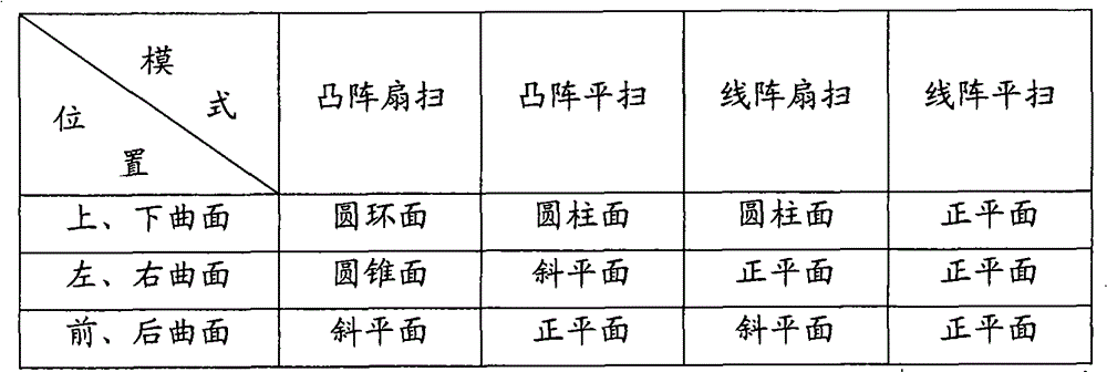
其中正平面是与坐标轴垂直的平面,斜平面是不与坐标轴垂直的平面。圆柱面是一条直线绕与之平行的一条直线旋转一周形成的曲面,圆锥面是一条射线绕过其端点的一条直线旋转一周形成的曲面,圆环面是一个圆绕与之共面的一条直线旋转一周形成的曲面。圆柱面的另一种定义是:一个圆沿与之所在平面垂直且过其圆心的直线移动所形成的曲面,本实施例将使用这种定义,并称这个圆为“基圆”,这条直线为“主轴”。而圆锥面、圆环面的共同特点是,它们都是一条曲线绕与之共面的一条直线旋转一周得到的曲面。通常称这条曲线为“母线”,这条直线为“旋转轴”,本实施例称圆环面的母线为“母圆”。按照本实施例的坐标系定义,主轴和旋转轴可以刚好与X轴或Z轴重合,这样的定义将给计算带来很大的便利。这时,基圆可以定义在垂直主轴的任意平面上,母线和母圆可以定义在经过旋转轴的任意平面上,但同样为计算便利起见,本实施例将它们指定到XY平面或YZ平面。The positive plane is the plane perpendicular to the coordinate axis, and the oblique plane is the plane not perpendicular to the coordinate axis. A cylindrical surface is a curved surface formed by rotating a straight line around a straight line parallel to it. A conical surface is a curved surface formed by a ray passing around a straight line at its endpoint. A torus is a curved surface formed by a circle surrounding a straight line coplanar with it. A surface formed by one rotation. Another definition of a cylindrical surface is: a curved surface formed by a circle moving along a straight line perpendicular to its plane and passing through its center of circle. This embodiment will use this definition and call this circle "base circle". The straight line is the "principal axis". The common feature of the conical surface and the torus is that they are all curved surfaces obtained by rotating a curve around a straight line coplanar with it. Usually this curve is referred to as "generator", and this straight line is referred to as "axis of rotation". In this embodiment, the generatrix of the torus is referred to as "generic circle". According to the definition of the coordinate system in this embodiment, the main axis and the rotation axis can just coincide with the X axis or the Z axis, and such a definition will bring great convenience to the calculation. At this time, the base circle can be defined on any plane perpendicular to the main axis, and the generatrix and parent circle can be defined on any plane passing through the rotation axis, but also for the convenience of calculation, this embodiment assigns them to the XY plane or YZ plane.
在上面定义的各种曲面中,平面、圆锥面、圆柱面都是在空间无限延伸的,圆环面虽然是有限的,但也存在冗余的部分。本实施例称上述曲面为“完备曲面”,重构六面体的各个表面实际只是上述曲面的一部分,称为“局部曲面”。例如,在线阵平扫采集模式下,各个完备曲面为平面,而局部曲面为空间中的长方形。若使用局部曲面进行计算,无论曲面表示还是光线裁剪都是非常复杂的。因此,本实施例的作法是:将局部曲面扩展为完备曲面,并使用六个完备曲面依次进行光线裁剪,将六次裁剪得到的区间求得交集,就是最终的光线裁剪结果。Among the various curved surfaces defined above, the plane, conical surface, and cylindrical surface all extend infinitely in space. Although the torus is limited, there are also redundant parts. In this embodiment, the above-mentioned curved surface is called a "complete curved surface", and each surface of the reconstructed hexahedron is actually only a part of the above-mentioned curved surface, which is called a "local curved surface". For example, in the line scan acquisition mode, each complete surface is a plane, and the local surface is a rectangle in space. If a local surface is used for calculation, both surface representation and ray clipping are very complicated. Therefore, the method of this embodiment is: expand the local curved surface into a complete surface, and use six complete curved surfaces to perform ray clipping in sequence, and obtain the intersection of the intervals obtained by the six clippings, which is the final ray clipping result.
为了进行光线裁剪,需要在光线与曲面相交时判断光线是穿入还是穿出重构六面体,因此需要给出各个曲面的法向量。若称向着几何体内部的方向为曲面的内侧,向着几何体外部的方向为曲面的外侧,则可以指定曲面法向量的正向为垂直曲面并指向曲面内侧的方向。为提高时间和空间效率,本实施例并没有逐点计算法向量,而是将整个曲面的法向量特征集中表示出来,本实施例称为“整体法向量”。平面上各点的法向量是相同的,因此可以整体给出准确值,本实施例称为“定量法向量”;而其他形状的曲面上各点法向量是随位置而变化的,但是可以整体给出定性值,本实施例称为“定性法向量”。定性法向量的表示方法看似不太严格,但是在后面可以看到,这样的表示方法足以满足本实施例计算的需要。In order to perform ray clipping, it is necessary to determine whether the ray penetrates or exits the reconstructed hexahedron when the ray intersects the surface, so the normal vector of each surface needs to be given. If the direction toward the inside of the geometry is called the inside of the surface, and the direction toward the outside of the geometry is the outside of the surface, then the positive direction of the surface normal vector can be specified as the direction perpendicular to the surface and pointing to the inside of the surface. In order to improve time and space efficiency, this embodiment does not calculate the normal vector point by point, but expresses the normal vector characteristics of the entire surface in a concentrated manner, which is called "overall normal vector" in this embodiment. The normal vectors of each point on the plane are the same, so an accurate value can be given as a whole. Given a qualitative value, this embodiment is referred to as a "qualitative normal vector". The expression method of the qualitative normal vector seems not to be strict, but it can be seen later that such an expression method is sufficient to meet the calculation needs of this embodiment.
以下将针对各种采集模式,给出组成重构六面体表面的六个完备曲面的表达式,并且按照上、下、左、右、前、后的顺序逐一给出。The expressions of the six complete surfaces constituting the reconstructed hexahedron surface will be given below for various acquisition modes, and they will be given one by one in the order of up, down, left, right, front, and back.
首先,讨论凸阵扇扫采集模式,如图5。上、下曲面为圆环面,在XY平面给出母圆方程为:First, discuss the convex array sector scan acquisition mode, as shown in Figure 5. The upper and lower curved surfaces are torus, and the parent circle equation is given in the XY plane as:
x2+(y-R)2=r2(1)x 2 +(yR) 2 =r 2 (1)
其中,R是母圆圆心到旋转轴的距离,由于上、下曲面的母圆是同心圆,其R值相同,计算公式为:Among them, R is the distance from the center of the parent circle to the axis of rotation. Since the parent circles of the upper and lower curved surfaces are concentric circles, their R values are the same, and the calculation formula is:
R=r0-R0(2)R=r 0 -R 0 (2)
r是母圆的半径,上、下曲面具有不同的r值。若将上曲面的r值另记作ru,则有r is the radius of the parent circle, and the upper and lower surfaces have different r values. If the r value of the upper surface is denoted as r u , then
ru=r0+yup0(3)r u =r 0 +y u p 0 (3)
若将下曲面的r值另记作rd,则有If the r value of the lower surface is denoted as r d , then we have
rd=r0+ydp0(4)r d =r 0 +y d p 0 (4)
由于圆环面的有效部分是母圆在X轴下方的部分旋转而成的,即满足y<0,那么将y替换为
展开该式,得Expanding this formula, we get
为消去根号,将两边平方并整理得To eliminate the root sign, square both sides and arrange
z4+2y2z2+2x2z2+(-2r2-2R2)z2+y4+2y2x2+(-2r2-2R2)y2+x4+(-2r2+2R2)x2+(r2-R2)2=0(7)z 4 +2y 2 z 2 +2x 2 z 2 +(-2r 2 -2R 2 )z 2 +y 4 +2y 2 x 2 +(-2r 2 -2R 2 )y 2 +x 4 +(-2r 2 +2R 2 )x 2 +(r 2 -R 2 ) 2 =0(7)
为了避免平方引起的增根,需加以限制条件In order to avoid the root increase caused by the square, it is necessary to restrict
r2-R2-x2-y2-z2≥0(8)r 2 -R 2 -x 2 -y 2 -z 2 ≥0(8)
式7和式8实际是与式6等价的有理化表示,本实施例将式7称作“扩展方程”,式8称作“约束条件”,它们联合构成了正确的上、下曲面方程。Equation 7 and Equation 8 are actually rational expressions equivalent to Equation 6. In this embodiment, Equation 7 is called "extended equation", and Equation 8 is called "constraint condition". They jointly form the correct upper and lower surface equations .
这里还需要给出上、下曲面的整体法向量。对于上曲面,圆环面外部对应重构六面体内部,因此法向量向外,定性法向量只需记录向外即可;对于下曲面,圆环面内部对应重构六面体内部,因此法向量向内,定性法向量只需记录向内即可。It is also necessary to give the overall normal vectors of the upper and lower surfaces. For the upper surface, the exterior of the torus corresponds to the interior of the reconstructed hexahedron, so the normal vector faces outward, and the qualitative normal vector only needs to be recorded outward; for the lower surface, the interior of the torus corresponds to the interior of the reconstructed hexahedron, so the normal vector faces inward , the qualitative normal vector only needs to be recorded inward.
以上给出了凸阵扇扫采集模式上、下曲面的准确表示方法,即表示为圆环面的方法。可以看到,该方程的形式较为复杂,而且次数较高,增加了光线裁剪过程中建立和求解联立方程的计算量。为简化曲面方程,达到进一步提高速度的目的,可以考虑曲面逼近方法。由于圆环面是XY面上的弓形绕X轴旋转得出的,因此一种较好的逼近方法是用主轴定义在X轴和Y轴上的椭圆逼近该弓形,从而可以用椭球面逼近圆环面。本实施例给出两种逼近方案,如图6。The above gives the accurate representation method of the upper and lower curved surfaces in the convex array sector scan acquisition mode, that is, the method expressed as a torus. It can be seen that the form of the equation is more complicated, and the degree is higher, which increases the calculation amount of establishing and solving simultaneous equations in the light clipping process. In order to simplify the surface equation and further increase the speed, the surface approximation method can be considered. Since the torus is obtained by rotating the bow on the XY plane around the X axis, a better approximation method is to approximate the bow with an ellipse whose main axis is defined on the X and Y axes, so that the circle can be approximated by an ellipsoid torus. This embodiment provides two approximation schemes, as shown in FIG. 6 .
方案一,令椭圆过ACE三点,则XY平面的椭圆方程可以直接写出Scheme 1, let the ellipse pass through the three points of ACE, then the elliptic equation of the XY plane can be written directly
其中r和R与式1中用到的变量相同。where r and R are the same variables used in Equation 1.
椭圆绕X轴旋转,得到椭球面的方程是The ellipse is rotated around the X axis, and the equation to obtain the ellipsoid is
方案二,令椭圆过BCD三点,则XY平面的椭圆方程可以表示成
其中r和R与式1中用到的变量相同,λ是待定系数。将D点坐标
上述椭圆绕X轴旋转,得到椭球面的方程:The above ellipse is rotated around the X axis to obtain the equation of the ellipsoid:
式13可化简为:Formula 13 can be simplified as:
式10和式14分别给出了方案一和方案二的表示方程。与原方案相比,无论方案一还是方案二,表示方程的次数都由四次降低为二次,而且不需要求解约束条件,因此可以有效减少建立和求解联立方程的计算量。另外,从图6可以看到,方案一的椭圆曲线与弓形曲线还存在一定偏差,而方案二的椭圆曲线几乎与弓形曲线完全重合。也就是说,方案二的曲线逼近准确程度很高,从而用椭球面逼近圆环面的准确程度也很高。虽然式14看似比式10复杂很多,但是由于曲面方程只需在重构环节中计算一次,由此增加的计算量可以忽略不计。因此,出于对速度和质量的折衷考虑,本实施例优选地选择方案二。Equation 10 and Equation 14 respectively give the expression equations of Scheme 1 and
另外,椭球面作为表1未给出的一种曲面形状,其整体法向量的标记方法与圆环面完全相同,即上曲面的定向法向量向外,下曲面的定向法向量向内。至此,给出了凸阵扇扫采集模式上、下曲面的表示方法。In addition, the ellipsoid is a surface shape not given in Table 1, and its overall normal vector is marked in the same way as the torus, that is, the oriented normal vector of the upper surface is outward, and the oriented normal vector of the lower surface is inward. So far, the representation methods of the upper and lower surfaces of the convex array sector scan acquisition mode are given.
凸阵扇扫采集模式的左、右曲面为圆锥面,在XY平面给出母线方程为:The left and right curved surfaces of the convex array fan-scan acquisition mode are conical surfaces, and the equation of the busbar in the XY plane is given as:
y=kx+R (15)y=kx+R (15)
其中R仍由式2给出,k是母线的斜率,左、右曲面具有不同的k值。若将左曲面的k值另记作kl,则有where R is still given by

若将右曲面的k值另记作kr,则有If the k value of the right curved surface is denoted as k r , then we have

其中φ是ROI张角,即ROI左沿和右沿的夹角,计算公式为Where φ is the ROI opening angle, that is, the angle between the left edge and the right edge of the ROI, and the calculation formula is

由于圆锥面的有效部分是母线在X轴下方的部分旋转而成的,即满足y<0,那么将y替换为
为消去根号,两边平方并整理得To eliminate the root sign, square both sides and arrange
z2+y2-k2x2-2kRx-R2=0(20)z 2 +y 2 -k 2 x 2 -2kRx-R 2 =0(20)
为了避免平方引起的增根,应该加以限制条件In order to avoid the root increase caused by the square, it should be restricted
-kx-R≥0(21)-kx-R≥0(21)
类似前面的定义,式20为扩展方程,式21为约束条件,它们联合构成了正确的左、右曲面方程。在此指出,在本实施例提到的各种曲面形状中,只有圆环面和圆锥面的曲面方程需要采用扩展方程和约束条件联合的方式,而其他各种曲面都将使用独立的方程表示。Similar to the previous definition, Equation 20 is an extended equation, and Equation 21 is a constraint condition, and they jointly form the correct left and right surface equations. It is pointed out here that among the various surface shapes mentioned in this embodiment, only the surface equations of the torus and conic surface need to use the combination of extended equations and constraints, while other various surfaces will be represented by independent equations .
另外,还需要给出左、右曲面的整体法向量。圆锥面的外部对应重构六面体的内部,其方向与圆锥尖指向方向一致。因此对于左曲面,定性法向量只需记录向右即可;对于右曲面,定性法向量只需记录向左即可。In addition, the global normal vectors of the left and right surfaces also need to be given. The exterior of the conical surface corresponds to the interior of the reconstructed hexahedron, and its direction is consistent with the pointing direction of the cone tip. Therefore, for the left surface, the qualitative normal vector only needs to be recorded to the right; for the right surface, the qualitative normal vector only needs to be recorded to the left.
凸阵扇扫采集模式的前、后曲面为斜平面。前曲面的表示方程为The front and back curved surfaces of the convex array sector scan acquisition mode are oblique planes. The expression equation of the front surface is
后曲面的表示方程为The expression equation of the back surface is
其中θ为扇扫张角,即采集首帧和末帧间的夹角,计算公式为Where θ is the fan sweep angle, that is, the angle between the first frame and the last frame of the acquisition, and the calculation formula is
θ=nθ0(24)θ=nθ 0 (24)
这里还需要给出前、后曲面的整体法向量。事实上,对于任意平面方程,将x、y、z的系数顺序排列构成的向量,将与平面法向量方向一致或相反。由于本实施例在给出式22和式23中已经注意到系数的符号,可以保证这样构成的向量是与平面法向量一致的。这样,前曲面的定量法向量为
以上给出了凸阵扇扫采集模式下的六个曲面方程和整体法向量,由此确定了该模式下的重构六面体表达方法。The six surface equations and the overall normal vector in the convex array sector scan acquisition mode are given above, and the reconstruction hexahedron expression method in this mode is determined.
现在讨论凸阵平扫采集模式。如图7所示,上、下曲面为圆柱面,在XY平面给出基圆方程为:Now discuss the convex scan acquisition mode. As shown in Figure 7, the upper and lower curved surfaces are cylindrical surfaces, and the equation of the base circle given in the XY plane is:
x2+y2=r2(25)x 2 +y 2 =r 2 (25)
对上曲面取r=ru,下曲面取r=rd,且ru和rd仍由式3和式4给出。Take r=r u for the upper curved surface, take r=r d for the lower curved surface, and r u and r d are still given by Equation 3 and Equation 4.
式25就是上、下曲面的表示方程,也就是说曲面表示方程与其基圆方程是完全相同的。Equation 25 is the expression equation of the upper and lower surfaces, that is to say, the expression equation of the surface is exactly the same as the equation of the base circle.
这里还需要给出上、下曲面的整体法向量。对于上曲面,圆柱面外部对应重构六面体内部,因此法向量向外,定性法向量只需记录向外即可;对于下曲面,圆柱面内部对应重构六面体内部,因此法向量向内,定性法向量只需记录向内即可。It is also necessary to give the overall normal vectors of the upper and lower surfaces. For the upper surface, the exterior of the cylindrical surface corresponds to the interior of the reconstructed hexahedron, so the normal vector faces outward, and the qualitative normal vector only needs to be recorded outward; for the lower surface, the interior of the cylindrical surface corresponds to the interior of the reconstructed hexahedron, so the normal vector faces inward, and the qualitative normal vector only needs to be recorded outward. Normal vectors need only be recorded inwards.
凸阵平扫采集模式的左、右曲面为斜平面。左曲面的表示方程为The left and right curved surfaces of the convex array flat-scan acquisition mode are oblique planes. The expression equation of the left curved surface is

右曲面的表示方程为The expression equation of the right curved surface is

左、右曲面的整体法向量已由平面方程隐含给出。The global normal vectors of the left and right surfaces are implicitly given by the plane equation.
凸阵平扫采集模式的前、后曲面为正平面。前曲面的表示方程为The front and back curved surfaces of the convex array flat-scan acquisition mode are positive planes. The expression equation of the front surface is
后曲面的表示方程为The expression equation of the back surface is
其中f为平扫行程,即采集首帧和末帧间的距离,计算公式为Among them, f is the flat scan stroke, that is, the distance between the first frame and the last frame of the acquisition, and the calculation formula is
f=nf0 (30)f=nf 0 (30)
前、后曲面的整体法向量已由平面方程隐含给出。The global normal vectors of the front and back surfaces are implicitly given by the plane equation.
以上给出了凸阵平扫采集模式下的六个曲面方程和整体法向量,由此确定了该模式下的重构六面体表达方法。The six surface equations and the overall normal vector in the convex array flat-scan acquisition mode are given above, and thus the reconstruction hexahedron expression method in this mode is determined.
现在讨论线阵扇扫采集模式。如图8所示,上、下曲面为圆柱面,在YZ平面给出基圆方程为:Now discuss the linear array sector scan acquisition mode. As shown in Figure 8, the upper and lower curved surfaces are cylindrical surfaces, and the equation of the base circle given in the YZ plane is:
y2+z2=r2 (31)y 2 +z 2 =r 2 (31)
r是基圆的半径,上、下曲面具有不同的r值。若将上曲面的r值另记作ru′,则有r is the radius of the base circle, and the upper and lower surfaces have different r values. If the r value of the upper surface is denoted as r u ′, then we have
ru′=R0+yup0(32)r u ′=R 0 +y u p 0 (32)
若将下曲面的r值另记作rd′,则有If the r value of the lower surface is denoted as r d ′, then we have
rd′=R0+ydp0(33)r d '=R 0 +y d p 0 (33)
式31就是上、下曲面的表示方程,也就是说曲面表示方程与其基圆方程是完全相同的。Equation 31 is the expression equation of the upper and lower surfaces, that is to say, the expression equation of the surface is exactly the same as the equation of the base circle.
这里还需要给出上、下曲面的整体法向量。对于上曲面,圆柱面外部对应重构六面体内部,因此法向量向外,定性法向量只需记录向外即可;对于下曲面,圆柱面内部对应重构六面体内部,因此法向量向内,定性法向量只需记录向内即可。It is also necessary to give the overall normal vectors of the upper and lower surfaces. For the upper surface, the exterior of the cylindrical surface corresponds to the interior of the reconstructed hexahedron, so the normal vector faces outward, and the qualitative normal vector only needs to be recorded outward; for the lower surface, the interior of the cylindrical surface corresponds to the interior of the reconstructed hexahedron, so the normal vector faces inward, and the qualitative normal vector only needs to be recorded outward. Normal vectors need only be recorded inwards.
线阵扇扫采集模式的左、右曲面为正平面。左曲面的表示方程为The left and right curved surfaces of the linear array sector scan acquisition mode are positive planes. The expression equation of the left curved surface is
右曲面的表示方程为The expression equation of the right curved surface is
其中l为ROI宽度,即ROI左沿与右沿之间的距离,计算公式为Where l is the width of the ROI, that is, the distance between the left edge and the right edge of the ROI, and the calculation formula is
l=(xr-xl)l0 (36)l=(x r -x l )l 0 (36)
其中左、右曲面的整体法向量已由平面方程隐含给出。The global normal vectors of the left and right surfaces are implicitly given by the plane equation.
线阵扇扫采集模式的前、后曲面为斜平面,其方程与凸阵扇扫采集模式的前、后曲面相同,见式22和式23。The front and rear curved surfaces of the linear array sector-sweep acquisition mode are oblique planes, and their equations are the same as those of the convex array sector-scan acquisition mode, see Equation 22 and Equation 23.
以上给出了线阵扇扫采集模式下的六个曲面方程和整体法向量,由此确定了该模式下的重构六面体表达方法。The six surface equations and the overall normal vector in the linear array sector-sweep acquisition mode are given above, and thus the reconstruction hexahedron expression method in this mode is determined.
现在讨论线阵平扫采集模式。如图9所示,上、下曲面为正平面,上曲面的表示方程为Now discuss the linear scan acquisition mode. As shown in Figure 9, the upper and lower curved surfaces are positive planes, and the expression equation of the upper curved surface is
下曲面的表示方程为The expression equation of the lower surface is
其中p为ROI高度,即ROI上沿与下沿之间的距离,计算公式为Where p is the ROI height, that is, the distance between the upper edge and the lower edge of the ROI, and the calculation formula is
p=(yd-yu)p0 (39)p=(y d -y u )p 0 (39)
上、下曲面的整体法向量已由平面方程隐含给出。The global normal vectors of the upper and lower surfaces are implicitly given by the plane equation.
线阵平扫采集模式的左、右曲面为正平面,其方程与线阵扇扫采集模式的左、右曲面相同,见式34和式35。The left and right curved surfaces of the linear array plain scan acquisition mode are positive planes, and its equation is the same as the left and right curved surfaces of the linear array sector scan acquisition mode, see formula 34 and formula 35.
线阵平扫采集模式的前、后曲面为正平面,其方程与凸阵平扫采集模式的前、后曲面相同,见式28和式29。The front and rear curved surfaces of the linear array plain scan acquisition mode are positive planes, and its equation is the same as that of the convex array plain scan acquisition mode, see Equation 28 and Equation 29.
至此,已经给出了所有采集模式下重构六面体的表达方法。这时,重构六面体被看作六个曲面组成的几何体,由于每个曲面的表达已经足够充分,因此在后面的光线裁剪中,将不再需要考虑当前的采集模式,也不需要考虑当前曲面来自上、下、左、右、前、后的哪个方向。So far, the expression methods for reconstructing the hexahedron in all acquisition modes have been given. At this time, the reconstructed hexahedron is regarded as a geometry composed of six surfaces. Since the expression of each surface is sufficient, it is no longer necessary to consider the current acquisition mode and the current surface in the subsequent ray clipping. Which direction from up, down, left, right, front, back.
以上表达是在几何体坐标系下给出的,而光线方程通常在体数据坐标系下给出,采样点插值也只能在体数据坐标系下完成,因此,需要能够给出两个坐标系下的坐标互相变换的方法。The above expressions are given in the geometry coordinate system, while the ray equation is usually given in the volume data coordinate system, and the sampling point interpolation can only be completed in the volume data coordinate system. Therefore, it is necessary to be able to give the two coordinate systems The method of mutual transformation of coordinates.
既然已经得到了重构体数据,必然知道它在X、Y、Z三个方向上的尺寸,记为WX、WY、WZ。由于几何体坐标系X、Z方向的原点都位于重构体数据在X、Z方向的中心位置,因此这两个方向的坐标变换关系很容易确定。为确定Y方向的坐标变换关系,设几何体坐标系原点距离重构体数据上表面为D,以向上为正。可以计算出,对于凸阵扇扫采集模式Now that the reconstructed body data has been obtained, its dimensions in the X, Y, and Z directions must be known, which are recorded as W X , W Y , and W Z . Since the origin of the geometry coordinate system in the X and Z directions is located at the center of the reconstructed volume data in the X and Z directions, the coordinate transformation relationship in these two directions is easy to determine. In order to determine the coordinate transformation relationship in the Y direction, the distance from the origin of the geometry coordinate system to the upper surface of the reconstructed volume data is D, and upward is positive. It can be calculated that for the convex array sector scan acquisition mode

对于凸阵平扫采集模式For convex scan acquisition mode

对于线阵扇扫采集模式For linear array sector scan acquisition mode
对于线阵平扫采集模式For line scan acquisition mode
至此,可以确定两个坐标系间的变换关系,设某点在几何体坐标系下的坐标为(x,y,z),该点在体数据坐标系下的坐标为(x’,y’,z’),则从几何体坐标系变换到体数据坐标系的变换关系是So far, the transformation relationship between the two coordinate systems can be determined. Let the coordinates of a point in the geometry coordinate system be (x, y, z), and the coordinates of the point in the volume data coordinate system be (x', y', z'), then the transformation relationship from the geometry coordinate system to the volume data coordinate system is
从体数据坐标系变换到几何体坐标系的方法是The method to transform from the volume data coordinate system to the geometry coordinate system is
以上完成了重构环节,现在开始执行绘制环节。如图10所示,是按照本发明实施例的用于超声成像的绘制方法的流程图。其中在裁剪步骤1001中,通过求解光线方程与重构六面体的每个曲面方程组成的方程组,将该光线在该曲面内侧的部分确定为该光线对该曲面的独立有效区间,对确定的六个独立有效区间求交集得到联合有效区间;以及在投射步骤1003中,利用光线对联合有效区间中的体数据进行采样,并对每个采样点进行插值与合成,以得到当前像素的灰度值;其中得到所有像素的灰度值后,就完成了绘制过程。下面对按照本实施例的用于超声成像的绘制方法进行具体说明。The reconstruction process is completed above, and now the drawing process is started. As shown in FIG. 10 , it is a flowchart of a drawing method for ultrasound imaging according to an embodiment of the present invention. Wherein in the
绘制方法仍然是基于光线投射算法的。设当前光线的起点为(Px,Py,Pz),由每个采样点到下一个采样点的向量为(dx,dy,dz),本实施例称这样的向量为当前光线的“步进向量”。这时,当前光线的姿态已经完全确定,可以计算出,第t个采样点的坐标(x,y,z)是The drawing method is still based on the ray casting algorithm. Assume that the starting point of the current ray is (P x , P y , P z ), and the vector from each sampling point to the next sampling point is (d x , d y , d z ). This embodiment calls such a vector the current The "step vector" for the ray. At this time, the attitude of the current ray has been completely determined, and it can be calculated that the coordinates (x, y, z) of the tth sampling point are
这可以看作关于t的参数方程,如果上述坐标是在体数据坐标系下给出的,则需要根据式44变换到几何体坐标系,得到几何体坐标系下的坐标(x,y,z),其表达式仍然是关于t的参数方程。This can be regarded as a parametric equation about t. If the above coordinates are given in the volume data coordinate system, it needs to be transformed to the geometry coordinate system according to Equation 44 to obtain the coordinates (x, y, z) in the geometry coordinate system, Its expression is still a parametric equation with respect to t.
对光线进行裁剪,实际就是求出满足采样点(x,y,z)在重构六面体范围内的参数t范围,本实施例称这样的范围为当前光线的“联合有效区间”。由于重构六面体的形状可能是不凸的,因此联合有效区间除了可能是空区间和一段连续区间之外,还可能是多段连续区间组成的集合。本实施例称这样的每个连续区间为联合有效区间的“连续区段”。事实上,对于已有的四种采集模式,联合有效区间最多由两个连续区段组成。为计算联合有效区间,本实施例将使用基于图形的解析方法,这与逐点查表计算方法具有本质的不同。Clipping the ray is actually finding the parameter t range that satisfies the sampling point (x, y, z) within the range of the reconstructed hexahedron. This embodiment calls such a range the "joint effective interval" of the current ray. Since the shape of the reconstructed hexahedron may be non-convex, the joint effective interval may not only be an empty interval and a continuous interval, but may also be a set composed of multiple continuous intervals. In this embodiment, each such continuous interval is referred to as a "continuous section" of the joint valid interval. In fact, for the four existing acquisition modes, the joint effective interval consists of at most two consecutive segments. In order to calculate the joint effective interval, this embodiment will use a graphics-based analysis method, which is essentially different from the point-by-point look-up table calculation method.
显然,各个连续区段的端点一定对应光线与某个曲面的交点。为了求得光线与曲面的交点,需要求解光线方程和曲面方程联立构成的方程组,本实施例称为“光线曲面方程组”。由于光线方程相对比较简单,通常是将光线方程代入曲面方程。如果曲面方程是由扩展方程和约束条件联合构成的,将光线方程代入扩展方程解出t之后,还需要将各个解代入约束条件检查是否适合,最终只保留适合的解。Obviously, the endpoints of each continuous segment must correspond to the intersection point of the ray with a certain surface. In order to obtain the intersection point of the ray and the curved surface, it is necessary to solve the equation system composed of the ray equation and the surface equation, which is called "ray surface equation system" in this embodiment. Since the ray equation is relatively simple, it is usually substituted into the surface equation. If the surface equation is composed of extended equations and constraints, after substituting the ray equation into the extended equation to solve for t, each solution needs to be substituted into the constraints to check whether it is suitable, and finally only the suitable solution is retained.
显然,若原来的曲面是N次的,则光线曲面方程组通常可以化为一个关于t的一元N次方程,本实施例称为“联立方程”。至于曲面的次数,与表面形状有关,其中平面为一次曲面,椭球面、圆锥面、圆柱面为二次曲面,圆环面为四次曲面,因此它们对应的N分别等于1,2,4。根据有关数学定理,四次以下的方程可以用解析方法求解,而高于四次的方程一般只能用数值方法求解。由于联立方程最高是四次的,因此都可以用解析方法求解。Apparently, if the original curved surface is of degree N, then the ray surface equations can usually be transformed into a one-variable N-degree equation about t, which is called "simultaneous equations" in this embodiment. As for the degree of the surface, it is related to the shape of the surface. The plane is a first-order surface, the ellipsoid, conical surface, and cylindrical surface are quadratic surfaces, and the torus is a quartic surface. Therefore, their corresponding N is equal to 1, 2, and 4 respectively. According to relevant mathematical theorems, equations of degree less than 4 can be solved analytically, while equations of degree higher than 4 can only be solved numerically. Since the simultaneous equations are of the highest order of quartics, they can be solved analytically.
光线与曲面的交点对应着联立方程的实数解,若其中有n重实数解,则需当作n个解处理。一般来说,一元N次方程最多有N个实数解,但对本实施例给出的情况,每个曲面与光线最多有两个交点,因此每个联立方程最多有两个实数解。本实施例不考虑无穷多个解的情况,此情况表示光线完全位于曲面上,实际是一种临界状态,可当作无解处理。The intersection of the light and the surface corresponds to the real number solutions of the simultaneous equations, if there are n multiple real number solutions, they need to be treated as n solutions. Generally speaking, a one-variable equation of degree N has at most N real number solutions, but for the situation given in this embodiment, there are at most two intersection points between each curved surface and light, so each simultaneous equation has at most two real number solutions. This embodiment does not consider the situation of infinitely many solutions, which means that the light rays are completely located on the curved surface, which is actually a critical state and can be treated as no solution.
对每个联立方程求解之后,还需要根据解集确定光线对当前曲面而言的有效区间,即光线在曲面内侧的部分,本实施例称这样的区间为当前曲面决定的“独立有效区间”。以下将根据曲面的不同形状,介绍由解集确定独立有效区间的方法。After solving each simultaneous equation, it is also necessary to determine the effective interval of the light for the current surface according to the solution set, that is, the part of the light on the inside of the surface. This embodiment refers to such an interval as the "independent effective interval" determined by the current surface . The following will introduce the method of determining the independent effective interval from the solution set according to the different shapes of the surface.
对于平面,根据平面的几何性质,光线与平面的联立方程可能得到0个解或一个解。若光线与平面平行,联立方程将得到0个解;若光线与平面相交,联立方程将得到一个解。For planes, the simultaneous equations of light and plane may have zero solutions or one solution, depending on the geometric properties of the plane. If the ray is parallel to the plane, the simultaneous equations will have zero solutions; if the ray intersects the plane, the simultaneous equations will have one solution.
若联立方程有0个解,将光线起点(Px,Py,Pz)代入平面方程的左边,若结果为正,则独立有效区间为全区间(-∞,+∞),否则独立有效区间为空区间Φ。If the simultaneous equation has 0 solutions, substitute the starting point of the ray (P x , P y , P z ) into the left side of the plane equation. If the result is positive, the independent effective interval is the full interval (-∞, +∞), otherwise the independent The valid interval is the empty interval Φ.
若联立方程有一个解,设其为t1。计算光线步进向量(dx,dy,dz)与平面法向量的点积,若点积为正,则独立有效区间为右区间(t1,+∞),否则独立有效区间为左区间(-∞,t1)。If the simultaneous equations have a solution, let it be t 1 . Calculate the dot product of the ray step vector (d x , d y , d z ) and the plane normal vector, if the dot product is positive, the independent effective interval is the right interval (t 1 , +∞), otherwise the independent effective interval is the left Interval (-∞, t 1 ).
对于圆柱面,根据圆柱面的几何性质,光线与圆柱面的联立方程可能得到0个解或两个解。若光线与圆柱面平行,联立方程将得到0个解;若光线与圆柱面相交两次,联立方程将得到两个解。For the cylindrical surface, according to the geometric properties of the cylindrical surface, the simultaneous equations of the ray and the cylindrical surface may have zero solutions or two solutions. If the ray is parallel to the cylinder, the simultaneous equation will have zero solutions; if the ray intersects the cylinder twice, the simultaneous equation will have two solutions.
若联立方程有0个解,当光线起点位于曲面内侧时,即光线起点位于圆柱内且定性法向量向内,或者光线起点位于圆柱外且定性法向量向外时,独立有效区间为全区间(-∞,+∞),否则独立有效区间为空区间Φ。If the simultaneous equation has 0 solutions, when the starting point of the ray is inside the surface, that is, the starting point of the ray is inside the cylinder and the qualitative normal vector is inward, or when the starting point of the ray is outside the cylinder and the qualitative normal vector is outward, the independent effective interval is the whole interval (-∞, +∞), otherwise the independent valid interval is the empty interval Φ.
若联立方程有两个解,设其为{t1,t2},当曲面法向量向外时,独立有效区间为外区间(-∞,t1)∪(t2,+∞);当曲面法向量向内时,独立有效区间为内区间(t1,t2)。If the simultaneous equation has two solutions, let it be {t 1 , t 2 }, when the normal vector of the surface faces outward, the independent effective interval is the outer interval (-∞, t 1 )∪(t 2 , +∞); When the surface normal vector faces inward, the independent effective interval is the inner interval (t 1 , t 2 ).
对于圆锥面,根据圆锥面的几何性质,光线与圆锥面的联立方程可能得到0个解、一个解或两个解。若光线与圆锥面相离,联立方程将得到0个解;若光线与圆锥面相交一次,联立方程将得到一个解;若光线与圆锥面相交两次,联立方程将得到两个解。For the conical surface, according to the geometric properties of the conical surface, the simultaneous equations of light and conical surface may have zero solutions, one solution or two solutions. If the ray passes away from the conical surface, the simultaneous equations will have zero solutions; if the ray intersects the conical surface once, the simultaneous equations will have one solution; if the ray intersects the conical surface twice, the simultaneous equations will have two solutions.
若联立方程有0个解,独立有效区间为全区间(-∞,+∞)。If the simultaneous equation has 0 solutions, the independent valid interval is the full interval (-∞, +∞).
若联立方程有一个解,设其为t1。当光线步进向量的X分量方向与圆锥面的定性法向量方向一致时,即dx>0且定性法向量向右,或dx<0且定性法向量向左时,独立有效区间为右区间(t1,+∞),否则独立有效区间为左区间(-∞,t1)。If the simultaneous equations have a solution, let it be t 1 . When the direction of the X component of the ray step vector is consistent with the direction of the qualitative normal vector of the conical surface, that is, d x >0 and the qualitative normal vector is to the right, or d x <0 and the qualitative normal vector is to the left, the independent valid interval is right interval (t 1 , +∞), otherwise the independent effective interval is the left interval (-∞, t 1 ).
若联立方程有两个解,设其为{t1,t2},独立有效区间为外区间(-∞,t1)∪(t2,+∞)。If the simultaneous equation has two solutions, let it be {t 1 , t 2 }, and the independent effective interval is the outer interval (-∞, t 1 )∪(t 2 , +∞).
对于圆环面,根据圆环面的几何性质,光线与圆环面的联立方程可能得到0个解或两个解。若光线与圆环面相离,联立方程将得到0个解;若光线与圆环面相交两次,联立方程将得到两个解。For the torus, according to the geometric properties of the torus, the simultaneous equations of the ray and the torus may have zero solutions or two solutions. If the ray departs from the torus, the simultaneous equations will have zero solutions; if the ray intersects the torus twice, the simultaneous equations will have two solutions.
若联立方程有0个解,当定性法向量向外时,独立有效区间为全区间(-∞,+∞);当定性法向量向内时,独立有效区间为空区间Φ。If the simultaneous equation has 0 solutions, when the qualitative normal vector faces outward, the independent effective interval is the full interval (-∞, +∞); when the qualitative normal vector faces inward, the independent effective interval is the empty interval Φ.
若联立方程有两个解,设其为{t1,t2},当定性法向量向外时,独立有效区间为外区间(-∞,t1)∪(t2,+∞);当定性法向量向内时,独立有效区间为内区间(t1,t2)。If the simultaneous equation has two solutions, let it be {t 1 , t 2 }, when the qualitative normal vector is outward, the independent effective interval is the outer interval (-∞, t 1 )∪(t 2 , +∞); When the qualitative normal vector is inward, the independent effective interval is the inner interval (t 1 , t 2 ).
对于椭球面,方法与圆环面完全相同。For an ellipsoid, the method is exactly the same as for a torus.
以上给出了各种曲面形状下由解集生成独立有效区间的方法。对重构六面体的六个表面,以此逐一计算,将得到六个独立有效区间。对六个独立有效区间求交集,就得到了联合有效区间,也就是用重构六面体对当前光线进行裁剪的结果。The methods for generating independent effective intervals from solution sets under various surface shapes are given above. For the six surfaces of the reconstructed hexahedron, six independent effective intervals will be obtained by calculating them one by one. The intersection of the six independent effective intervals is obtained to obtain the joint effective interval, which is the result of clipping the current ray with the reconstructed hexahedron.
在本实施例中提出的联合有效区间是以解析方法计算出的,每个连续区段的起点对应的参数t可以是小数,因此可以将各段光线的起点准确定位到重构六面体的表面,从而解决了走样问题。The joint effective interval proposed in this embodiment is calculated by analytical method, and the parameter t corresponding to the starting point of each continuous segment can be a decimal number, so the starting point of each segment of light can be accurately positioned on the surface of the reconstructed hexahedron, Thus solving the aliasing problem.
完成光线裁剪之后,可以依据联合有效区间进行当前光线的投射。若联合有效区间的连续区段个数为零,表示光线与重构六面体没有交点,可直接结束当前光线投射。若联合有效区间的连续区段个数不为零,则从第一个连续区段的起点开始进行采样,并按照步进向量逐步行进。若有两个连续区段,且采样点到达第一个连续区段的终点时还没有满足光线中止条件,则从第二个连续区段的起点开始采样,并按照步进向量逐步行进。总之,结束当前光线投射的条件是,要么采样点到达最后一个连续区段的终点,要么满足光线中止条件。另外,光线投射中应用联合有效区间的方法还可改变,例如当出现多个连续区段时,可取从第一个连续区段起点到最后一个连续区段终点之间的区间作为光线步进的有效范围。After the ray clipping is completed, the current ray can be cast according to the joint valid interval. If the number of continuous segments in the joint effective interval is zero, it means that the ray does not intersect with the reconstructed hexahedron, and the current ray casting can be ended directly. If the number of continuous segments in the joint effective interval is not zero, sampling is performed from the starting point of the first continuous segment, and progresses step by step according to the step vector. If there are two continuous segments, and the ray termination condition has not been satisfied when the sampling point reaches the end of the first continuous segment, start sampling from the start point of the second continuous segment, and proceed step by step according to the step vector. In short, the condition for ending the current ray casting is that either the sampling point reaches the end of the last continuous segment, or the ray termination condition is satisfied. In addition, the method of applying joint effective intervals in ray casting can also be changed. For example, when there are multiple continuous segments, the interval from the start point of the first continuous segment to the end point of the last continuous segment can be taken as the ray step Effective range.
对当前光线经过的每个采样点进行插值和合成,最终得到当前光线的合成结果,也就是当前像素的灰度值。当所有的像素位置都得到了灰度值,就完成了绘制环节,这时得到的结果就是可视信息,可送入显示设备进行显示。Interpolation and synthesis are performed on each sampling point that the current ray passes through, and finally the synthesis result of the current ray is obtained, that is, the gray value of the current pixel. When all pixel positions have obtained gray values, the drawing process is completed, and the result obtained at this time is visual information, which can be sent to the display device for display.
如图11所示,是按照本实施例的三维超声成像装置的结构框图,包括采集模块1101、重构装置1103和绘制装置1105,其中采集模块1101用于获取三维超声体数据。As shown in FIG. 11 , it is a structural block diagram of a three-dimensional ultrasound imaging device according to this embodiment, including an
重构装置1103进一步包括生成模块1113、构造模块1123和变换模块1133。其中生成模块1113用于从原始体数据生成重构体数据;构造模块1123根据采集模式确定重构六面体的各面形状,并根据采集姿态参数确定出重构六面体各面的曲面方程(包括但不限于完备曲面方程),由曲面的交割构成重构六面体,以给出重构六面体的整体图形化表达;以及变换模块1133根据重构体数据确定体数据坐标至几何体坐标的变换关系,以将体数据坐标变换至几何体坐标。The
绘制装置1105进一步包括裁剪模块1115和投射模块1125。其中裁剪模块1115通过求解光线方程与重构六面体的每个曲面方程组成的方程组,将该光线在该曲面内侧的部分确定为该光线对该曲面的独立有效区间,对六个独立有效区间求交集得到联合有效区间;以及投射模块1125利用光线对联合有效区间中的体数据进行采样,并对每个采样点进行插值与合成,以得到当前像素的灰度值;得到所有像素的灰度值后,就完成了绘制过程。The
按照本实施例的上述各模块可以通过软件、硬件或者固件、以及软件、硬件或者固件的组合来实现。The above-mentioned modules according to this embodiment may be implemented by software, hardware or firmware, or a combination of software, hardware or firmware.
图12是结合了按照本实施例的三维超声成像装置的成像系统框图。一组通过延迟聚焦的脉冲通过发射电路发送到探头,探头向受测机体组织发射超声波,经一定延时后接收从受测机体组织反射回来的超声波。回波信号进入波束合成器,完成聚焦延时、加权和通道求和。其输出信号经过信号处理,再经按照本实施例的三维超声成像装置处理后,就可以通过显示设备进行显示。当然,按照本实施例的三维超声成像装置也可以通过软件、硬件或者固件、以及软件、硬件或者固件的组合实现在各种超声成像系统中。Fig. 12 is a block diagram of an imaging system incorporating the three-dimensional ultrasonic imaging apparatus according to the present embodiment. A group of delayed focused pulses are sent to the probe through the transmitting circuit, and the probe transmits ultrasonic waves to the body tissue under test, and receives the ultrasonic waves reflected from the body tissue under test after a certain delay. The echo signal enters the beamformer to complete focusing delay, weighting and channel summation. After the output signal is processed by the three-dimensional ultrasonic imaging device according to this embodiment, it can be displayed by the display device. Of course, the three-dimensional ultrasonic imaging device according to this embodiment can also be implemented in various ultrasonic imaging systems by software, hardware or firmware, or a combination of software, hardware or firmware.
以上通过具体的实施例对本发明进行了说明,但本发明并不限于这些具体的实施例。具体来说,重构六面体中的具体表示方法可以改变,例如:(1)采集模式不一定局限为本实施例给出的四种,如果出现其他模式,可以仿照本实施例的方法进行计算和表示;(2)采集姿态参数的具体形式可以改变,例如以像素为单位可以改为以毫米为单位,ROI左沿位置与右沿位置可以改为ROI左沿位置与左右距离,等等,只需将计算公式进行适当的转换,最终可以达到同样的效果;(3)局部曲面不一定需要扩展为完备曲面,可以直接使用局部曲面进行表示和计算;其中局部曲面的完整表达可以由一个完备曲面方程和若干个限制条件联合构成。在进行光线裁剪时,先以完备曲面求出有效范围,再根据限制条件对此范围进行取舍,可以得到光线相对于当前局部曲面的裁剪结果;(4)完备曲面的范围可以变化,例如凸阵扇扫模式上曲面的完备曲面可以表示为满足Y<0的半圆环面;(5)凸阵扇扫模式上下曲面的准确形状为圆环面,在通常情况下,可以近似表示为椭球面;(6)凸阵扇扫模式左右曲面的准确形状为圆锥面,在扇扫张角θ较小的情况下,可以近似表示为平面,平面方程与式15给出的母线方程相同;(6)线阵扇扫模式上曲面的准确形状为圆柱面,在其半径ru′较小的情况下,可以忽略该曲面,这时重构六面体退化为五面体,也就是说,图形表达使用的曲面个数为六个并不是必须的;(7)不一定使用整体法向量和定性法向量,例如可以逐点计算准确法向量;(8)几何体坐标系的定义方法可以改变,例如凸阵扇扫和线阵扇扫模式,Y方向原点位置原来定义在扇扫旋转轴处,可以改为定义在探头圆心处,这时曲面表示方程将相应改变,几何体坐标系与体数据坐标系之间的变换关系也将相应改变。其次,利用重构六面体对光线进行裁剪的具体方法可以改变。例如:(1)进行光线裁剪前可进行一些预处理,如可首先将重构六面体投影到视平面,得到视平面内的一个有效区域,这样可以预先淘汰不经过有效区域内像素的光线;(2)由光线曲面方程组得到联立方程的方法可以改变,本发明是将光线方程代入曲面方程,可以改为将曲面方程参数化后代入光线方程;(3)求解联立方程的方法可以改变,例如可以将解析方法改为数值方法,另外当出现无穷多个解的情况时,解集可以由取空集改为取全集;(4)由解集确定独立有效区间的方法可以改变,例如二次方程出现两个相等实根时,本发明将此情况与两个不等实根的情况等同处理,可以改为对此情况作专门处理;(5)在确定独立有效区间时应用法向量的方法可改变,例如可由应用整体法向量改为应用交点处的准确法向量。再次,光线投射的实现方法可以改变,例如:(1)投影方式可以改变,除了使用透视投影,还可以改用平行投影等方法;(2)插值方法可以改变,除了使用三线性插值,还可以改用最近邻插值等方法;(3)合成方法可以改变,除了使用吸收-发散模型进行合成,还可以改用最大值合成、最小值合成、X-Ray合成等方法。The present invention has been described above through specific examples, but the present invention is not limited to these specific examples. Specifically, the specific representation method in the reconstructed hexahedron can be changed, for example: (1) the acquisition modes are not necessarily limited to the four types given in this embodiment, if other modes appear, the method of this embodiment can be used to calculate and (2) The specific form of the acquisition attitude parameters can be changed, for example, the unit of pixel can be changed to millimeter, the left edge position and right edge position of ROI can be changed to the left edge position and left and right distance of ROI, etc., only The calculation formula needs to be properly converted to achieve the same effect; (3) The local surface does not necessarily need to be expanded into a complete surface, and the local surface can be directly used for expression and calculation; the complete expression of the local surface can be represented by a complete surface Equations and several constraints are combined to form. When performing ray clipping, the effective range is first obtained with the complete surface, and then the range is selected according to the constraints, and the clipping result of the light relative to the current local surface can be obtained; (4) The range of the complete surface can be changed, such as a convex array The complete surface of the upper surface in the sector-sweep mode can be expressed as a semi-circular surface satisfying Y<0; (5) The exact shape of the upper and lower surfaces in the convex array sector-sweep mode is a torus, which can be approximately expressed as an ellipsoid under normal circumstances ; (6) The exact shape of the left and right curved surfaces of the convex array fan-sweep mode is a conical surface, which can be approximately expressed as a plane when the fan-sweep angle θ is small, and the plane equation is the same as the generatrix equation given by Equation 15; (6 ) The exact shape of the curved surface in the linear array sector sweep mode is a cylindrical surface, and the curved surface can be ignored when the radius r u ′ is small. At this time, the reconstructed hexahedron degenerates into a pentahedron, that is to say, the graphic expression used The number of surfaces is not necessarily six; (7) It is not necessary to use the overall normal vector and qualitative normal vector, for example, the exact normal vector can be calculated point by point; (8) The definition method of the geometric coordinate system can be changed, such as the convex array fan In scan and linear array sector scan modes, the origin position in the Y direction is originally defined at the sector scan rotation axis, but can be changed to be defined at the center of the probe circle. At this time, the surface representation equation will be changed accordingly, and the coordinate system between the geometric body and the volume data coordinate system The transformation relationship will also change accordingly. Second, the specific method of clipping rays using the reconstructed hexahedron can vary. For example: (1) Some preprocessing can be performed before ray clipping. For example, the reconstructed hexahedron can be projected onto the viewing plane first to obtain an effective area in the viewing plane, so that rays that do not pass through pixels in the effective area can be eliminated in advance; ( 2) the method that obtains simultaneous equations by ray surface equations can be changed, and the present invention is that ray equations are substituted into surface equations, which can be changed into ray equations after the parameterization of surface equations; (3) the method for solving simultaneous equations can be changed , for example, the analytical method can be changed to a numerical method. In addition, when there are infinitely many solutions, the solution set can be changed from an empty set to a complete set; (4) the method of determining an independent valid interval from the solution set can be changed, for example When two equal real roots appear in the quadratic equation, the present invention handles this situation with the situation of two unequal real roots, and can change this situation into a special treatment; (5) apply the normal vector when determining the independent valid interval The method of can be changed, for example, from applying the global normal vector to applying the exact normal vector at the intersection point. Again, the implementation method of ray casting can be changed, for example: (1) the projection method can be changed, in addition to using perspective projection, parallel projection and other methods can also be used instead; (2) the interpolation method can be changed, in addition to using trilinear interpolation, you can also use Use methods such as nearest neighbor interpolation instead; (3) The synthesis method can be changed. In addition to using the absorption-divergence model for synthesis, you can also use methods such as maximum value synthesis, minimum value synthesis, and X-Ray synthesis.
本领域技术人员应该明白,还可以对本发明做各种其他修改、等同替换、变化等等,例如将上述实施例中的一个步骤或模块分为两个或更多个步骤或模块来实现,或者相反,将上述实施例中的两个或更多个步骤或模块的功能放在一个步骤或模块中来实现。但是,这些变换只要未背离本发明的精神,都应在本发明的保护范围之内。另外,本申请说明书和权利要求书所使用的一些术语,例如“上”、“下”、“左”、“右”、“前”、“后”等等,都是相对的,并不是限制,仅仅是为了便于描述。Those skilled in the art should understand that various other modifications, equivalent replacements, changes, etc. can also be made to the present invention, such as dividing one step or module in the above-mentioned embodiment into two or more steps or modules to implement, or On the contrary, the functions of two or more steps or modules in the above embodiments are implemented in one step or module. However, as long as these changes do not deviate from the spirit of the present invention, they should all be within the protection scope of the present invention. In addition, some terms used in the specification and claims of this application, such as "upper", "lower", "left", "right", "front", "rear", etc., are relative and not limiting , for ease of description only.
Claims (27)
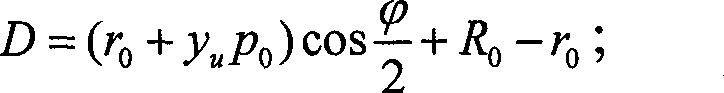
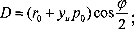

Priority Applications (1)
| Application Number | Priority Date | Filing Date | Title |
|---|---|---|---|
| CN 200910104840 CN101770650B (en) | 2009-01-07 | 2009-01-07 | Three-dimensional ultrasound real-time imaging method and device and imaging system |
Applications Claiming Priority (1)
| Application Number | Priority Date | Filing Date | Title |
|---|---|---|---|
| CN 200910104840 CN101770650B (en) | 2009-01-07 | 2009-01-07 | Three-dimensional ultrasound real-time imaging method and device and imaging system |
Publications (2)
| Publication Number | Publication Date |
|---|---|
| CN101770650A CN101770650A (en) | 2010-07-07 |
| CN101770650B true CN101770650B (en) | 2013-04-24 |
Family
ID=42503498
Family Applications (1)
| Application Number | Title | Priority Date | Filing Date |
|---|---|---|---|
| CN 200910104840 Active CN101770650B (en) | 2009-01-07 | 2009-01-07 | Three-dimensional ultrasound real-time imaging method and device and imaging system |
Country Status (1)
| Country | Link |
|---|---|
| CN (1) | CN101770650B (en) |
Families Citing this family (13)
| Publication number | Priority date | Publication date | Assignee | Title |
|---|---|---|---|---|
| CN102397082B (en) | 2010-09-17 | 2013-05-08 | 深圳迈瑞生物医疗电子股份有限公司 | Method and device for generating direction indicating diagram and ultrasonic three-dimensional imaging method and system |
| CN103645474B (en) * | 2013-12-12 | 2016-02-24 | 北京无线电计量测试研究所 | For the formation method of the two dimensional image of millimeter wave 3-D imaging system |
| CN104463942B (en) * | 2014-10-31 | 2017-07-28 | 上海联影医疗科技有限公司 | 3-D view method of cutting out and device |
| US10692272B2 (en) | 2014-07-11 | 2020-06-23 | Shanghai United Imaging Healthcare Co., Ltd. | System and method for removing voxel image data from being rendered according to a cutting region |
| US11403809B2 (en) | 2014-07-11 | 2022-08-02 | Shanghai United Imaging Healthcare Co., Ltd. | System and method for image rendering |
| CN106846445B (en) * | 2016-12-08 | 2019-08-27 | 华中科技大学 | A CPU-based 3D Ultrasonic Image Volume Rendering Method |
| US20180182157A1 (en) * | 2016-12-25 | 2018-06-28 | Biosense Webster (Israel) Ltd. | Fast rendering of quadrics |
| US10529119B2 (en) * | 2016-12-25 | 2020-01-07 | Biosense Webster (Israel) Ltd. | Fast rendering of quadrics and marking of silhouettes thereof |
| CN109975814B (en) * | 2017-12-28 | 2020-09-22 | 深圳先进技术研究院 | Ultrasound imaging method, system and device |
| CN112912010B (en) * | 2018-10-22 | 2024-09-24 | 皇家飞利浦有限公司 | Method and system for deriving parameters related to flow from a blood vessel |
| CN109358371B (en) * | 2018-11-08 | 2021-12-24 | 上海英迈吉东影图像设备有限公司 | Luggage article safety inspection method of CT security inspection machine |
| CN109598784A (en) * | 2018-11-20 | 2019-04-09 | 哈尔滨理工大学 | A kind of efficient backbone tomoscan image three-dimensional rebuilding method |
| CN116664471A (en) * | 2022-02-18 | 2023-08-29 | 青岛海信医疗设备股份有限公司 | Coordinate transformation method and related device for two-dimensional ultrasonic imaging |
Citations (4)
| Publication number | Priority date | Publication date | Assignee | Title |
|---|---|---|---|---|
| CN1555764A (en) * | 2004-01-06 | 2004-12-22 | 华南师范大学 | Method and device for optical and ultrasonic acquisition and tomographic imaging of biological tissue |
| CN2936150Y (en) * | 2006-07-07 | 2007-08-22 | 柯依 | Three-dimension mammary gland ultrasonic scan detecting system |
| CN101283929A (en) * | 2008-06-05 | 2008-10-15 | 华北电力大学 | A Reconstruction Method of Three-Dimensional Model of Blood Vessel |
| US7538764B2 (en) * | 2001-01-05 | 2009-05-26 | Interuniversitair Micro-Elektronica Centrum (Imec) | System and method to obtain surface structures of multi-dimensional objects, and to represent those surface structures for animation, transmission and display |
-
2009
- 2009-01-07 CN CN 200910104840 patent/CN101770650B/en active Active
Patent Citations (4)
| Publication number | Priority date | Publication date | Assignee | Title |
|---|---|---|---|---|
| US7538764B2 (en) * | 2001-01-05 | 2009-05-26 | Interuniversitair Micro-Elektronica Centrum (Imec) | System and method to obtain surface structures of multi-dimensional objects, and to represent those surface structures for animation, transmission and display |
| CN1555764A (en) * | 2004-01-06 | 2004-12-22 | 华南师范大学 | Method and device for optical and ultrasonic acquisition and tomographic imaging of biological tissue |
| CN2936150Y (en) * | 2006-07-07 | 2007-08-22 | 柯依 | Three-dimension mammary gland ultrasonic scan detecting system |
| CN101283929A (en) * | 2008-06-05 | 2008-10-15 | 华北电力大学 | A Reconstruction Method of Three-Dimensional Model of Blood Vessel |
Non-Patent Citations (1)
| Title |
|---|
| 朱玉云等.基于曲面拟合法的肝脏超声成像仿真数学建模.《生物医学工程与临床》.2008,第12卷(第6期),443. * |
Also Published As
| Publication number | Publication date |
|---|---|
| CN101770650A (en) | 2010-07-07 |
Similar Documents
| Publication | Publication Date | Title |
|---|---|---|
| CN101770650B (en) | Three-dimensional ultrasound real-time imaging method and device and imaging system | |
| CN100522066C (en) | Ultrasonic diagnostic equipment and image processing method | |
| Huang et al. | Bezier interpolation for 3-D freehand ultrasound | |
| CN102106741B (en) | Three-dimensional reconstruction method for two-dimensional ultrasonic image | |
| CN101292883B (en) | Ultrasonic three-dimensional quick imaging method and apparatus | |
| US20040081340A1 (en) | Image processing apparatus and ultrasound diagnosis apparatus | |
| CN102436672B (en) | Ultrasonic image processing apparatus | |
| US11484286B2 (en) | Ultrasound evaluation of anatomical features | |
| CN106683176A (en) | Visceral organ three-dimensional model construction method and device | |
| CN102081697B (en) | Method and device for defining interested volume in ultrasonic imaging space | |
| EP3654292B1 (en) | Three-dimensional ultrasound image display method | |
| US8059914B2 (en) | Method and apparatus for preprocessing ultrasound imaging | |
| CN114998150B (en) | Method and device for three-dimensional reconstruction of ultrasonic images | |
| CN102949206B (en) | A kind of method of 3-D supersonic imaging and device | |
| CN103761767A (en) | Quick three-dimensional ultrasound image reconstruction method based on sparse data | |
| US20070201737A1 (en) | System And Method For Vascular Visualization Using Planar Reformation Of Vascular Central Axis Surface With Biconvex Slab | |
| CN103371849B (en) | Ultrasonic image-forming system and method | |
| US12089997B2 (en) | System and methods for image fusion | |
| CN103860197A (en) | Free type three-dimensional ultrasonic imaging method, device and system | |
| WO2022133806A1 (en) | Fetal face volume image inpainting method and ultrasound imaging system | |
| US6458082B1 (en) | System and method for the display of ultrasound data | |
| CN112638267B (en) | Ultrasound imaging method and system, storage medium, processor and computer equipment | |
| CN112654301A (en) | Imaging method of spine and ultrasonic imaging system | |
| CN104361623A (en) | Portable three-dimensional imaging sonar and imaging method and system thereof | |
| CN120279211B (en) | Three-dimensional reconstruction method for ultrasonic image, computer equipment and storage medium |
Legal Events
| Date | Code | Title | Description |
|---|---|---|---|
| C06 | Publication | ||
| PB01 | Publication | ||
| C10 | Entry into substantive examination | ||
| SE01 | Entry into force of request for substantive examination | ||
| C14 | Grant of patent or utility model | ||
| GR01 | Patent grant | ||
| EE01 | Entry into force of recordation of patent licensing contract |
Application publication date: 20100707 Assignee: Shenzhen Mindray Animal Medical Technology Co.,Ltd. Assignor: SHENZHEN MINDRAY BIO-MEDICAL ELECTRONICS Co.,Ltd. Contract record no.: X2022440020009 Denomination of invention: Three-dimensional ultrasound real-time imaging method and device and imaging system Granted publication date: 20130424 License type: Common License Record date: 20220804 |
|
| EE01 | Entry into force of recordation of patent licensing contract |