CN101755383A - Motor control device, drive device, and hybrid drive device - Google Patents
Motor control device, drive device, and hybrid drive device Download PDFInfo
- Publication number
- CN101755383A CN101755383A CN200880025467A CN200880025467A CN101755383A CN 101755383 A CN101755383 A CN 101755383A CN 200880025467 A CN200880025467 A CN 200880025467A CN 200880025467 A CN200880025467 A CN 200880025467A CN 101755383 A CN101755383 A CN 101755383A
- Authority
- CN
- China
- Prior art keywords
- motor
- voltage
- slope
- power supply
- converter
- Prior art date
- Legal status (The legal status is an assumption and is not a legal conclusion. Google has not performed a legal analysis and makes no representation as to the accuracy of the status listed.)
- Granted
Links
Images


Classifications
-
- B—PERFORMING OPERATIONS; TRANSPORTING
- B60—VEHICLES IN GENERAL
- B60L—PROPULSION OF ELECTRICALLY-PROPELLED VEHICLES; SUPPLYING ELECTRIC POWER FOR AUXILIARY EQUIPMENT OF ELECTRICALLY-PROPELLED VEHICLES; ELECTRODYNAMIC BRAKE SYSTEMS FOR VEHICLES IN GENERAL; MAGNETIC SUSPENSION OR LEVITATION FOR VEHICLES; MONITORING OPERATING VARIABLES OF ELECTRICALLY-PROPELLED VEHICLES; ELECTRIC SAFETY DEVICES FOR ELECTRICALLY-PROPELLED VEHICLES
- B60L7/00—Electrodynamic brake systems for vehicles in general
- B60L7/10—Dynamic electric regenerative braking
-
- B—PERFORMING OPERATIONS; TRANSPORTING
- B60—VEHICLES IN GENERAL
- B60L—PROPULSION OF ELECTRICALLY-PROPELLED VEHICLES; SUPPLYING ELECTRIC POWER FOR AUXILIARY EQUIPMENT OF ELECTRICALLY-PROPELLED VEHICLES; ELECTRODYNAMIC BRAKE SYSTEMS FOR VEHICLES IN GENERAL; MAGNETIC SUSPENSION OR LEVITATION FOR VEHICLES; MONITORING OPERATING VARIABLES OF ELECTRICALLY-PROPELLED VEHICLES; ELECTRIC SAFETY DEVICES FOR ELECTRICALLY-PROPELLED VEHICLES
- B60L15/00—Methods, circuits, or devices for controlling the traction-motor speed of electrically-propelled vehicles
- B60L15/02—Methods, circuits, or devices for controlling the traction-motor speed of electrically-propelled vehicles characterised by the form of the current used in the control circuit
- B60L15/025—Methods, circuits, or devices for controlling the traction-motor speed of electrically-propelled vehicles characterised by the form of the current used in the control circuit using field orientation; Vector control; Direct Torque Control [DTC]
-
- B—PERFORMING OPERATIONS; TRANSPORTING
- B60—VEHICLES IN GENERAL
- B60L—PROPULSION OF ELECTRICALLY-PROPELLED VEHICLES; SUPPLYING ELECTRIC POWER FOR AUXILIARY EQUIPMENT OF ELECTRICALLY-PROPELLED VEHICLES; ELECTRODYNAMIC BRAKE SYSTEMS FOR VEHICLES IN GENERAL; MAGNETIC SUSPENSION OR LEVITATION FOR VEHICLES; MONITORING OPERATING VARIABLES OF ELECTRICALLY-PROPELLED VEHICLES; ELECTRIC SAFETY DEVICES FOR ELECTRICALLY-PROPELLED VEHICLES
- B60L15/00—Methods, circuits, or devices for controlling the traction-motor speed of electrically-propelled vehicles
- B60L15/02—Methods, circuits, or devices for controlling the traction-motor speed of electrically-propelled vehicles characterised by the form of the current used in the control circuit
- B60L15/08—Methods, circuits, or devices for controlling the traction-motor speed of electrically-propelled vehicles characterised by the form of the current used in the control circuit using pulses
-
- H—ELECTRICITY
- H02—GENERATION; CONVERSION OR DISTRIBUTION OF ELECTRIC POWER
- H02P—CONTROL OR REGULATION OF ELECTRIC MOTORS, ELECTRIC GENERATORS OR DYNAMO-ELECTRIC CONVERTERS; CONTROLLING TRANSFORMERS, REACTORS OR CHOKE COILS
- H02P21/00—Arrangements or methods for the control of electric machines by vector control, e.g. by control of field orientation
- H02P21/0085—Arrangements or methods for the control of electric machines by vector control, e.g. by control of field orientation specially adapted for high speeds, e.g. above nominal speed
- H02P21/0089—Arrangements or methods for the control of electric machines by vector control, e.g. by control of field orientation specially adapted for high speeds, e.g. above nominal speed using field weakening
-
- H—ELECTRICITY
- H02—GENERATION; CONVERSION OR DISTRIBUTION OF ELECTRIC POWER
- H02P—CONTROL OR REGULATION OF ELECTRIC MOTORS, ELECTRIC GENERATORS OR DYNAMO-ELECTRIC CONVERTERS; CONTROLLING TRANSFORMERS, REACTORS OR CHOKE COILS
- H02P3/00—Arrangements for stopping or slowing electric motors, generators, or dynamo-electric converters
- H02P3/06—Arrangements for stopping or slowing electric motors, generators, or dynamo-electric converters for stopping or slowing an individual dynamo-electric motor or dynamo-electric converter
- H02P3/08—Arrangements for stopping or slowing electric motors, generators, or dynamo-electric converters for stopping or slowing an individual dynamo-electric motor or dynamo-electric converter for stopping or slowing a DC motor
- H02P3/14—Arrangements for stopping or slowing electric motors, generators, or dynamo-electric converters for stopping or slowing an individual dynamo-electric motor or dynamo-electric converter for stopping or slowing a DC motor by regenerative braking
-
- B—PERFORMING OPERATIONS; TRANSPORTING
- B60—VEHICLES IN GENERAL
- B60L—PROPULSION OF ELECTRICALLY-PROPELLED VEHICLES; SUPPLYING ELECTRIC POWER FOR AUXILIARY EQUIPMENT OF ELECTRICALLY-PROPELLED VEHICLES; ELECTRODYNAMIC BRAKE SYSTEMS FOR VEHICLES IN GENERAL; MAGNETIC SUSPENSION OR LEVITATION FOR VEHICLES; MONITORING OPERATING VARIABLES OF ELECTRICALLY-PROPELLED VEHICLES; ELECTRIC SAFETY DEVICES FOR ELECTRICALLY-PROPELLED VEHICLES
- B60L2210/00—Converter types
- B60L2210/10—DC to DC converters
- B60L2210/12—Buck converters
-
- B—PERFORMING OPERATIONS; TRANSPORTING
- B60—VEHICLES IN GENERAL
- B60L—PROPULSION OF ELECTRICALLY-PROPELLED VEHICLES; SUPPLYING ELECTRIC POWER FOR AUXILIARY EQUIPMENT OF ELECTRICALLY-PROPELLED VEHICLES; ELECTRODYNAMIC BRAKE SYSTEMS FOR VEHICLES IN GENERAL; MAGNETIC SUSPENSION OR LEVITATION FOR VEHICLES; MONITORING OPERATING VARIABLES OF ELECTRICALLY-PROPELLED VEHICLES; ELECTRIC SAFETY DEVICES FOR ELECTRICALLY-PROPELLED VEHICLES
- B60L2210/00—Converter types
- B60L2210/10—DC to DC converters
- B60L2210/14—Boost converters
-
- B—PERFORMING OPERATIONS; TRANSPORTING
- B60—VEHICLES IN GENERAL
- B60L—PROPULSION OF ELECTRICALLY-PROPELLED VEHICLES; SUPPLYING ELECTRIC POWER FOR AUXILIARY EQUIPMENT OF ELECTRICALLY-PROPELLED VEHICLES; ELECTRODYNAMIC BRAKE SYSTEMS FOR VEHICLES IN GENERAL; MAGNETIC SUSPENSION OR LEVITATION FOR VEHICLES; MONITORING OPERATING VARIABLES OF ELECTRICALLY-PROPELLED VEHICLES; ELECTRIC SAFETY DEVICES FOR ELECTRICALLY-PROPELLED VEHICLES
- B60L2210/00—Converter types
- B60L2210/40—DC to AC converters
- B60L2210/42—Voltage source inverters
-
- B—PERFORMING OPERATIONS; TRANSPORTING
- B60—VEHICLES IN GENERAL
- B60L—PROPULSION OF ELECTRICALLY-PROPELLED VEHICLES; SUPPLYING ELECTRIC POWER FOR AUXILIARY EQUIPMENT OF ELECTRICALLY-PROPELLED VEHICLES; ELECTRODYNAMIC BRAKE SYSTEMS FOR VEHICLES IN GENERAL; MAGNETIC SUSPENSION OR LEVITATION FOR VEHICLES; MONITORING OPERATING VARIABLES OF ELECTRICALLY-PROPELLED VEHICLES; ELECTRIC SAFETY DEVICES FOR ELECTRICALLY-PROPELLED VEHICLES
- B60L2240/00—Control parameters of input or output; Target parameters
- B60L2240/40—Drive Train control parameters
- B60L2240/42—Drive Train control parameters related to electric machines
- B60L2240/421—Speed
-
- B—PERFORMING OPERATIONS; TRANSPORTING
- B60—VEHICLES IN GENERAL
- B60L—PROPULSION OF ELECTRICALLY-PROPELLED VEHICLES; SUPPLYING ELECTRIC POWER FOR AUXILIARY EQUIPMENT OF ELECTRICALLY-PROPELLED VEHICLES; ELECTRODYNAMIC BRAKE SYSTEMS FOR VEHICLES IN GENERAL; MAGNETIC SUSPENSION OR LEVITATION FOR VEHICLES; MONITORING OPERATING VARIABLES OF ELECTRICALLY-PROPELLED VEHICLES; ELECTRIC SAFETY DEVICES FOR ELECTRICALLY-PROPELLED VEHICLES
- B60L2240/00—Control parameters of input or output; Target parameters
- B60L2240/40—Drive Train control parameters
- B60L2240/42—Drive Train control parameters related to electric machines
- B60L2240/423—Torque
-
- Y—GENERAL TAGGING OF NEW TECHNOLOGICAL DEVELOPMENTS; GENERAL TAGGING OF CROSS-SECTIONAL TECHNOLOGIES SPANNING OVER SEVERAL SECTIONS OF THE IPC; TECHNICAL SUBJECTS COVERED BY FORMER USPC CROSS-REFERENCE ART COLLECTIONS [XRACs] AND DIGESTS
- Y02—TECHNOLOGIES OR APPLICATIONS FOR MITIGATION OR ADAPTATION AGAINST CLIMATE CHANGE
- Y02T—CLIMATE CHANGE MITIGATION TECHNOLOGIES RELATED TO TRANSPORTATION
- Y02T10/00—Road transport of goods or passengers
- Y02T10/60—Other road transportation technologies with climate change mitigation effect
- Y02T10/64—Electric machine technologies in electromobility
-
- Y—GENERAL TAGGING OF NEW TECHNOLOGICAL DEVELOPMENTS; GENERAL TAGGING OF CROSS-SECTIONAL TECHNOLOGIES SPANNING OVER SEVERAL SECTIONS OF THE IPC; TECHNICAL SUBJECTS COVERED BY FORMER USPC CROSS-REFERENCE ART COLLECTIONS [XRACs] AND DIGESTS
- Y02—TECHNOLOGIES OR APPLICATIONS FOR MITIGATION OR ADAPTATION AGAINST CLIMATE CHANGE
- Y02T—CLIMATE CHANGE MITIGATION TECHNOLOGIES RELATED TO TRANSPORTATION
- Y02T10/00—Road transport of goods or passengers
- Y02T10/60—Other road transportation technologies with climate change mitigation effect
- Y02T10/72—Electric energy management in electromobility
-
- Y—GENERAL TAGGING OF NEW TECHNOLOGICAL DEVELOPMENTS; GENERAL TAGGING OF CROSS-SECTIONAL TECHNOLOGIES SPANNING OVER SEVERAL SECTIONS OF THE IPC; TECHNICAL SUBJECTS COVERED BY FORMER USPC CROSS-REFERENCE ART COLLECTIONS [XRACs] AND DIGESTS
- Y02—TECHNOLOGIES OR APPLICATIONS FOR MITIGATION OR ADAPTATION AGAINST CLIMATE CHANGE
- Y02T—CLIMATE CHANGE MITIGATION TECHNOLOGIES RELATED TO TRANSPORTATION
- Y02T90/00—Enabling technologies or technologies with a potential or indirect contribution to GHG emissions mitigation
- Y02T90/10—Technologies relating to charging of electric vehicles
- Y02T90/16—Information or communication technologies improving the operation of electric vehicles
Landscapes
- Engineering & Computer Science (AREA)
- Power Engineering (AREA)
- Transportation (AREA)
- Mechanical Engineering (AREA)
- Control Of Ac Motors In General (AREA)
- Electric Propulsion And Braking For Vehicles (AREA)
- Control Of Motors That Do Not Use Commutators (AREA)
- Hybrid Electric Vehicles (AREA)
- Dc-Dc Converters (AREA)
Abstract
Description
技术领域technical field
本发明涉及控制从逆变器向电动机供电的电力和其逆方向的再生电力的电动机控制装置,特别涉及逆变器施加于电动机的动作电压和电压控制模式的控制。本发明的电动机控制装置,例如能够使用于由电动机驱动车轮的电动汽车(EV),以及在该电动机之外还具有燃料发动机和由该发动机旋转驱动的发电机(也被称作电动机或发电动机)的混合电动汽车(HEV)。The present invention relates to a motor control device for controlling the power supplied from an inverter to a motor and the regenerative power in the reverse direction thereof, and particularly relates to the control of the operating voltage applied to the motor by the inverter and the voltage control mode. The motor control device of the present invention can be used, for example, in an electric vehicle (EV) whose wheels are driven by an electric motor, and which has, in addition to the electric motor, a fuel engine and a generator (also referred to as an electric motor or generator) rotationally driven by the engine. ) of hybrid electric vehicles (HEV).
背景技术Background technique
随着电动机的旋转速度的上升,在定子线圈产生的反电动势上升,由此,从逆变器向定子线圈的目标电流的供给变得困难,不能够得到作为目标的转矩输出。在该情况下,为了实现赋予的电动机目标转矩而使计算出的d轴电流id和q轴电流iq下降,虽然导致电力使用效率下降,但能够以更高的旋转速度输出目标转矩。这被称为弱磁控制。As the rotation speed of the motor increases, the counter electromotive force generated in the stator coil increases, thereby making it difficult to supply a target current from the inverter to the stator coil, and a target torque output cannot be obtained. In this case, reducing the calculated d-axis current id and q-axis current iq in order to realize the given motor target torque results in a decrease in power usage efficiency, but the target torque can be output at a higher rotational speed. This is called field weakening control.
专利文献1记载有一种电动机驱动控制装置,其为了消除由弱磁控制引起的电力损失和系统效率的下降,具有省略弱磁控制,使施加于逆变器的动作电压变高的升压电路,在电池电压对于电动机的目标动作不足时,从升压电路向逆变器进行供电。专利文献2记载有一种电动机驱动控制装置,其具有对电池电压进行升压的电路,计算与电动机的目标动作和速度电动势对应的所需要的升压电压,控制升压电路以成为该升压电压。专利文献3记载有一种电动机驱动控制装置,其在目标旋转速度成为超过基底旋转速度Rb的区域中,控制逆变器和升压电路,使得成为使弱磁损失和升压损失的和为最小的弱磁电流以及升压比。在专利文献4中记载有一种电动机控制装置,分别检测作为升压电路的转换器的电力损失和逆变器的电力损失,仅在弱磁控制区域,控制转换器和逆变器,使得两者均衡,在弱磁控制区域外,控制电流使得电动机驱动电压进入规定范围内。
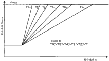
例如,在具有升压功能的电动汽车(EV)或混合电动汽车(HEV)中,在现有的方式中,为了减少由弱磁电流引起的电力损失,施加于驱动电动机的逆变器的中间直流电压(由转换器升压后的电压:转换器的次级电压),与电动机的目标转矩和旋转速度相对应地,在不需要弱磁电流的区域中为三相PWM(SVpwm)或二相PWM(Dpwm),在需要弱磁电流的区域中,也以其为0(调制比Mi为0.707保持一定,电压控制模式为Dpwm)的方式决定。例如,在转矩一定的情况下,决定次级侧目标电压Vuc*,使得中间直流电压如图6所示,随着旋转速度ω的上升,以一定的倾斜度上升至上限值Vmax。在中间直流电压达到上限值Vmax以后,考虑进行弱磁控制,之后将电压控制模式从Dpwm切换为全相矩形波通电的1pulse模式。For example, in an electric vehicle (EV) or a hybrid electric vehicle (HEV) with a boost function, in the conventional system, in order to reduce the power loss caused by the field-weakening current, a DC voltage (voltage boosted by the converter: secondary voltage of the converter), corresponding to the target torque and rotation speed of the motor, three-phase PWM (SVpwm) or in an area where field weakening current is not required The two-phase PWM (Dpwm) is also determined so that it is 0 (the modulation ratio Mi is kept constant at 0.707, and the voltage control mode is Dpwm) in the region where the field-weakening current is required. For example, when the torque is constant, the secondary side target voltage Vuc * is determined so that the intermediate DC voltage rises to the upper limit value Vmax with a constant gradient as the rotation speed ω increases, as shown in FIG. 6 . After the intermediate DC voltage reaches the upper limit value Vmax, consider performing field weakening control, and then switch the voltage control mode from Dpwm to 1pulse mode of full-phase rectangular wave energization.
专利文献1:日本特开平10-66383号公报Patent Document 1: Japanese Patent Application Laid-Open No. 10-66383
专利文献2:日本专利第3746334号公报Patent Document 2: Japanese Patent No. 3746334
专利文献3:日本特开2005-210772号公报Patent Document 3: Japanese Patent Laid-Open No. 2005-210772
专利文献4:日本特开2003-33071号公报Patent Document 4: Japanese Patent Laid-Open No. 2003-33071
在上述现有的中间直流电压的决定方式中,在电动机的旋转速度高的区域中,有时也使用SVpwm、DPWM,结果存在不能够使损失减小的问题。In the above-mentioned conventional method of determining the intermediate DC voltage, SVpwm and DPWM are sometimes used even in a region where the rotational speed of the motor is high, and as a result, there is a problem that losses cannot be reduced.
发明内容Contents of the invention
本发明的目的在于减少电动机的高速旋转时的电力损失。An object of the present invention is to reduce power loss during high-speed rotation of a motor.
为了达成上述目的,在本发明中,基于电动机的驱动的、至少在两相进行PWM通电的调制模式中不进行弱磁控制的第一区域、在比转换器的最大电压(Vmax)小的电压下在至少以两相进行PWM通电的调制模式中进行弱磁控制的第三区域、和在比上述转换器的最大电压小的电压下对全相进行矩形波通电的1pulse模式中进行弱磁控制的第二区域(图4)中的某一个,以决定次级侧目标电压,该次级侧目标电压决定施加于逆变器的次级电压。实施该内容的本发明的第一方式的电动机控制装置,如下述(1)项。In order to achieve the above object, in the present invention, in the first region where field weakening control is not performed in at least two-phase PWM energization modulation mode based on motor drive, the voltage is lower than the maximum voltage (Vmax) of the converter. Next, field weakening control is performed in the third region in which field weakening control is performed in modulation mode in which at least two phases are PWM energized, and field weakening control is performed in 1 pulse mode in which rectangular wave energization is performed on all phases at a voltage lower than the maximum voltage of the above-mentioned converter. One of the second regions (Fig. 4) to determine the secondary side target voltage, which determines the secondary voltage applied to the inverter. The motor control device according to the first aspect of the present invention which implements this content is described in the following item (1).
(1)一种电动机控制装置,包括:(1) A motor control device comprising:
逆变器(19m),其将初级侧直流电源(18、22)的输出供向电动机(10m),控制电动机(10m)的驱动;an inverter (19m), which supplies the output of the primary-side DC power supply (18, 22) to the motor (10m), and controls the driving of the motor (10m);
转换器(30c),其具有:升压供电装置(25、26、29),其对上述初级侧直流电源的电压进行升压,并作为次级电压(Vuc)向上述逆变器供电;和再生供电装置(27),其将来自上述逆变器的再生电力向上述初级侧直流电源进行逆供电;a converter (30c) having: a step-up power supply device (25, 26, 29) for boosting the voltage of the above-mentioned primary-side DC power supply, and supplying power to the above-mentioned inverter as a secondary voltage (Vuc); and A regenerative power supply device (27), which reversely supplies the regenerative power from the above-mentioned inverter to the above-mentioned primary-side DC power supply;
次级侧目标电压决定单元(图3的5),其基于上述电动机的驱动的、至少在两相进行PWM通电的调制模式中不进行弱磁控制的第一区域、在比上述转换器的最大电压小的电压下在至少以两相进行PWM通电的调制模式中进行弱磁控制的第三区域、和在比上述转换器的最大电压小的电压下对全相进行矩形波通电的1pulse模式中进行弱磁控制的第二区域(图4)中的某一个,来决定次级侧目标电压(Vuc*m);The secondary-side target voltage determination unit (5 in FIG. 3 ) is based on a first region in which field weakening control is not performed in at least two-phase PWM energization modulation mode of the drive of the above-mentioned motor, and is greater than the maximum voltage of the above-mentioned converter. In the third region, field-weakening control is performed in modulation mode in which at least two phases are PWM energized at a low voltage, and in the 1-pulse mode in which rectangular wave energization is performed in all phases at a voltage lower than the maximum voltage of the above-mentioned converter One of the second areas (Figure 4) for field weakening control is used to determine the secondary side target voltage (Vuc*m);
转换器控制单元(30v),其控制上述转换器的升压供电单元和再生供电单元,使得上述次级电压为上述次级侧目标电压;以及a converter control unit (30v) that controls the boost power supply unit and regenerative power supply unit of the converter so that the secondary voltage becomes the secondary side target voltage; and
电动机控制单元(30m),其基于上述电动机的目标转矩(T*)、旋转速度(ω)和上述次级电压(Vuc),控制上述逆变器,使得该电动机的输出转矩为上述目标转矩。a motor control unit (30m) that controls the above-mentioned inverter so that the output torque of the motor is the above-mentioned target torque.
另外,为了容易理解,在括号内将附图所示的后述的实施例的对应或相当要素或事项的符号,作为例示添加以进行参照。以下也是同样的。In addition, in order to facilitate understanding, symbols corresponding to or equivalent elements or matters in the embodiments shown in the drawings described later are added as examples and referred to in parentheses. The following is also the same.
综上所述,通过插入第三区域(ω1~ω2),能够使电压控制模式为1pulse的扩展1pulse模式区域。在1pulse模式中逆变器的开关损失较少,因此当1pulse模式扩展时,高旋转速度的区域的电力损失大幅变低。此外,通过应用1pulse模式,能够抑制涡电流的产生,结果能够减少铁损。To sum up, by inserting the third region (ω1˜ω2), the voltage control mode can be extended to the 1pulse mode region of 1pulse. In the 1pulse mode, the switching loss of the inverter is small, so when the 1pulse mode is extended, the power loss in the region of high rotational speed becomes significantly lower. In addition, by applying the 1pulse mode, generation of eddy current can be suppressed, and as a result, iron loss can be reduced.
(2)在上述(1)所述的电动机控制装置中,上述次级侧目标电压决定单元(图3的5),在上述第二区域中,根据上述电动机的目标转矩(T*)的上升使上述次级侧目标电压(Vuc*m)上升。(2) In the motor control device described in (1) above, the secondary side target voltage determining means (5 in FIG. 3 ) in the second region, based on the target torque (T * ) of the motor The increase increases the above-mentioned secondary side target voltage (Vuc*m).
(3)在上述(1)或(2)所述的电动机控制装置中,上述次级侧目标电压决定单元(图3的5),基于针对上述电动机的每个目标转矩(T*)的次级侧目标电压特性,决定上述次级侧目标电压(Vuc*m),该次级侧目标电压特性是:在上述第一区域(图4),随着上述电动机的旋转速度的上升以第一斜率(k1)上升;在上述第三区域,在上述电动机的旋转速度为开始弱磁控制的第一旋转速度(ω1)以上时以与第一斜率(k1)不同的第三斜率(k3)上升;在上述第二区域,在上述电动机的旋转速度为切换至上述1pulse模式的第三旋转速度(ω2)以上时以与第三斜率不同的第二斜率(k2)上升。(3) In the motor control device described in the above (1) or (2), the secondary side target voltage determining means (5 in FIG. 3 ) is based on The secondary side target voltage characteristic determines the above secondary side target voltage (Vuc*m). A slope (k1) rises; in the above-mentioned third region, when the rotation speed of the above-mentioned motor is higher than the first rotation speed (ω1) at which field weakening control starts, a third slope (k3) different from the first slope (k1) is used Rise: in the second region, when the rotation speed of the motor is equal to or higher than the third rotation speed (ω2) for switching to the 1pulse mode, it rises with a second slope (k2) different from the third slope.
此外,为了达成上述目的,在本发明中,使用分配给电动机的目标转矩(T*)的、在至少以两相进行PWM通电的调制模式中随着旋转速度(ω)的上升,以大斜率的第一斜率(k1)上升,在开始弱磁控制的第一旋转速度(ω1)中切换为小斜率的第三斜率(k3),在将调制模式切换为对全相进行矩形波通电的1pulse模式的第二旋转速度(ω2)中切换为与第三斜率(k3)不同的第二斜率(k2)的次级侧目标电压特性(图4),导出与上述电动机(10m)的旋转速度对应的次级侧目标电压(Vuc*m)。即,使得现有技术的在同一目标转矩中随着旋转速度的上升以一定的大斜率上升的次级侧目标电压特性(图6),为图4所示,在开始弱磁控制时的旋转速度下切换为小斜率的第三斜率(k3),在使电压控制模式为1pulse模式时,切换为1pulse模式用的第二斜率(k2)。实施该内容的本发明的第二方式的电动机控制装置,如下面的(4)项In addition, in order to achieve the above object, in the present invention, in the modulation pattern of PWM energization in at least two phases using the target torque (T * ) distributed to the motor, as the rotation speed (ω) rises, the The first slope (k1) of the slope rises, and it switches to the third slope (k3) with a small slope at the first rotation speed (ω1) at which field weakening control starts, and when the modulation mode is switched to rectangular wave energization for all phases The secondary side target voltage characteristic (Fig. 4) of switching to the second slope (k2) different from the third slope (k3) at the second rotation speed (ω2) in 1pulse mode is derived from the rotation speed of the above-mentioned motor (10m) Corresponding secondary side target voltage (Vuc*m). That is, the secondary-side target voltage characteristic (Fig. 6), which makes the same target torque in the prior art rise with a certain large slope with the increase of the rotation speed, is shown in Fig. 4 when the field weakening control is started. The third slope ( k3 ) which is switched to a small slope at the rotation speed is switched to the second slope ( k2 ) for the 1 pulse mode when the voltage control mode is set to the 1 pulse mode. The motor control device of the second aspect of the present invention implementing this content is as follows (4) item
(4)一种电动机控制装置,包括:(4) A motor control device, comprising:
逆变器(19m),其将初级侧直流电源(18、22)的输出供向电动机(10m),控制电动机的驱动(10m);an inverter (19m), which supplies the output of the primary-side DC power supply (18, 22) to the motor (10m), and controls the driving of the motor (10m);
转换器(30c),其具有:升压供电装置(25、26、29),其对上述初级侧直流电源的电压进行升压,并作为次级电压(Vuc)向上述逆变器供电;和再生供电装置(27),其对来自上述逆变器的再生电力进行降压并向上述初级侧直流电源进行逆供电;a converter (30c) having: a step-up power supply device (25, 26, 29) for boosting the voltage of the above-mentioned primary-side DC power supply, and supplying power to the above-mentioned inverter as a secondary voltage (Vuc); and A regenerative power supply device (27), which steps down the regenerative power from the above-mentioned inverter and reversely supplies power to the above-mentioned primary-side DC power supply;
次级侧目标电压决定单元(图3的5),其针对上述电动机的每个目标转矩(T*),基于次级侧目标电压特性(图4),导出次级侧目标电压(Vuc*m),该次级侧目标电压特性是:根据上述电动机的旋转速度的上升,在至少以两相进行PWM通电的调制模式中以第一斜率(k1)上升,在开始弱磁控制的第一旋转速度(ω1)中切换为与第一斜率不同的第三斜率(k3),在将调制模式切换为对全相进行矩形波通电的1pulse模式的第二旋转速度(ω2)中切换为与第三斜率(k3)不同的第二斜率(k2)直至上升至上述转换器的最大电压(Vmax);The secondary side target voltage determination unit (5 in FIG. 3 ) derives the secondary side target voltage (Vuc* m), the secondary side target voltage characteristic is: according to the increase of the rotation speed of the above-mentioned motor, it increases with the first slope (k1) in the modulation mode of performing PWM energization in at least two phases, and at the first start of the field weakening control Switch to the third slope (k3) different from the first slope at the rotation speed (ω1), and switch to the second rotation speed (ω2) at the second rotation speed (ω2) that switches the modulation mode to the 1-pulse mode that energizes all phases with a rectangular wave. Three slopes (k3) with a different second slope (k2) up to the maximum voltage (Vmax) of the above-mentioned converter;
转换器控制单元(30v),其控制上述转换器(30c)的升压供电单元(25、26、29)和再生供电单元(27),使得上述次级电压(Vuc)为上述次级侧目标电压(Vuc*m);以及a converter control unit (30v) that controls the step-up power supply unit (25, 26, 29) and regenerative power supply unit (27) of the above-mentioned converter (30c) so that the above-mentioned secondary voltage (Vuc) is the above-mentioned secondary side target voltage (Vuc*m); and
电动机控制单元(30m),其基于上述电动机的目标转矩、旋转速度和上述次级侧目标电压,控制上述逆变器,使得该电动机的输出转矩为上述目标转矩。A motor control unit (30m) that controls the inverter so that the output torque of the motor becomes the target torque based on the target torque, rotation speed, and secondary-side target voltage of the motor.
据此,通过插入第三斜率(k3)的次级侧目标电压区域(ω1~ω2),能够使1pulse模式区域扩展。在1pulse模式中逆变器的开关损失较少,因此当1pulse模式扩展时,高旋转速度的区域的电力损失大幅变低。此外,通过应用1pulse模式,能够抑制涡电流的产生,结果能够减少铁损。Accordingly, by inserting the secondary-side target voltage range (ω1 to ω2) of the third slope (k3), the 1-pulse mode range can be expanded. In the 1pulse mode, the switching loss of the inverter is small, so when the 1pulse mode is extended, the power loss in the region of high rotational speed becomes significantly lower. In addition, by applying the 1pulse mode, generation of eddy current can be suppressed, and as a result, iron loss can be reduced.
在本发明的后述的实施例中,使得弱磁控制开始前的第一斜率(k1)>1pulse模式的第二斜率(k2)>弱磁控制开始后的第三斜率(k3)。这样,弱磁电流值较小的PWM控制区域(第三斜率k3的区域)扩展,此外,1pulse模式(第二斜率k2)的区域扩展,在大的旋转速度范围内逆变器的电力损失的抑制效率高。In the later-described embodiments of the present invention, the first slope (k1) before the start of the field weakening control>the second slope (k2) in the 1 pulse mode>the third slope (k3) after the start of the field weakening control. In this way, the PWM control area (the area of the third slope k3) with a small field-weakening current value is expanded, and the area of the 1pulse mode (the second slope k2) is expanded, and the power loss of the inverter is reduced in a large rotation speed range. High inhibition efficiency.
(5)在上述(3)或(4)所述的电动机控制装置中,上述第一斜率(k1)的倾斜度大于第三斜率(k3),上述第二斜率(k2)的倾斜度大于上述第三斜率,上述第二斜率是比上述第三斜率大的斜率。(5) In the motor control device described in the above (3) or (4), the inclination of the first slope (k1) is larger than the third slope (k3), and the inclination of the second slope (k2) is larger than the above-mentioned The third slope, the above-mentioned second slope is a slope larger than the above-mentioned third slope.
(6)如上述(3)~(5)中任一项所述的电动机控制装置,上述第二斜率(k2)是比第一斜率(k1)小的值。(6) The motor control device according to any one of (3) to (5) above, wherein the second slope (k2) is a smaller value than the first slope (k1).
(7)如上述(3)~(6)中任一项所述的电动机控制装置,上述电动机控制单元(30m),在上述第三斜率(k3)的速度区域(ω1~ω2)中,使上述调制模式为二相调制。(7) The motor control device according to any one of (3) to (6) above, wherein the motor control unit (30m) uses the speed range (ω1 to ω2) of the third slope (k3) The above modulation mode is two-phase modulation.
(8)如上述(3)~(7)中任一项所述的电动机控制装置,上述次级侧目标电压特性(图4)中,目标转矩越大,次级侧目标电压(Vuc*m)越高。(8) The motor control device according to any one of (3) to (7) above, wherein in the secondary side target voltage characteristic ( FIG. 4 ), the larger the target torque, the higher the secondary side target voltage (Vuc* m) is higher.
(9)如上述(3)~(8)中任一项所述的电动机控制装置,上述第三斜率(k3)是目标转矩越大就越大的值。(9) The motor control device according to any one of (3) to (8) above, wherein the third slope (k3) is a value that increases as the target torque increases.
(10)如上述(3)~(9)中任一项所述的电动机控制装置,上述第一斜率(k1)是,开始弱磁控制之前的三相调制或二相调制时的、使作为电动机目标电压(Vm*)与上述转换器的次级电压(Vuc)的比的调制比(Mi=Vm*/Vuc)为第一设定值(0.707)的值。(10) The motor control device according to any one of (3) to (9) above, wherein the first slope (k1) is set as The modulation ratio (Mi=Vm*/Vuc) of the ratio of the motor target voltage (Vm * ) to the converter's secondary voltage (Vuc) is a value of the first set value (0.707).
(11)如上述(10)所述的电动机控制装置,上述第二斜率(k2)是,在1pulse调制模式中,使作为电动机目标电压(Vm*)与上述转换器的次级电压(Vuc)的比的调制比(Mi=Vm*/Vuc)为第二设定值(0.78)时的值。(11) The motor control device according to the above (10), wherein the second slope (k2) is set to be the motor target voltage (Vm * ) and the secondary voltage (Vuc) of the converter in the 1pulse modulation mode. The modulation ratio (Mi=Vm*/Vuc) of the ratio is the value when the second set value (0.78) is obtained.
(12)如上述(11)所述的电动机控制装置,上述三相调制或二相调制时的、作为电动机目标电压与上述转换器的次级电压的比的调制比,小于作为电动机目标电压与上述转换器的次级电压的比的调制比。(12) In the motor control device described in (11) above, the modulation ratio, which is the ratio of the motor target voltage to the secondary voltage of the converter during the three-phase modulation or two-phase modulation, is smaller than the ratio between the motor target voltage and the secondary voltage of the converter. The modulation ratio above the ratio of the converter's secondary voltage.
(13)如上述(4)所述的电动机控制装置,上述第三斜率(k3),与同一目标转矩中的从第一旋转速度向第二旋转速度的速度上升相对应地,使次级侧目标电压从分配于第一旋转速度(ω1)的次级电压目标值上升至分配于第二旋转速度(ω2)的次级侧目标电压。(13) The motor control device according to (4) above, wherein the third gradient (k3) is set so that the secondary The side target voltage rises from the secondary voltage target value assigned to the first rotation speed (ω1) to the secondary side target voltage assigned to the second rotation speed (ω2).
(14)如上述(4)所述的电动机控制装置,上述次级侧目标电压特性(图4),相对于同一目标转矩,存在动力运行用和再生用,上述次级侧目标电压决定单元,基于目标转矩和旋转速度判定是“动力运行”还是“再生”,如果是“动力运行”则基于动力运行用的次级侧目标电压特性,如果是“再生”则基于再生用的次级侧目标电压特性,导出与上述电动机的旋转速度对应的次级侧目标电压(Vuc*m)。(14) In the motor control device described in (4) above, the secondary side target voltage characteristic ( FIG. 4 ) has power running and regeneration for the same target torque, and the secondary side target voltage determining means , based on the target torque and rotation speed to determine whether it is "power running" or "regeneration", if it is "power running", it is based on the secondary side target voltage characteristics for power running, if it is "regeneration", it is based on the secondary side for regeneration The side target voltage characteristic derives the secondary side target voltage (Vuc*m) corresponding to the rotation speed of the above-mentioned electric motor.
(15)一种驱动装置,其包括:上述(1)~(14)中任一项所述的电动机控制装置;和电动机,其由该电动机控制装置的上述逆变器供电,并驱动车轮。(15) A driving device including: the motor control device described in any one of (1) to (14) above; and a motor powered by the inverter of the motor control device and driving wheels.
(16)一种混合动力驱动装置,包括:(16) A hybrid drive comprising:
驱动车轮的第一电动机(10m);A first electric motor (10m) driving the wheels;
被燃料发动机旋转驱动的第二电动机(10g);a second electric motor (10g) driven in rotation by the fuel engine;
第一逆变器(19m),其将初级侧直流电源(18、22)的输出供向第一电动机(10m),控制第一电动机的驱动;a first inverter (19m), which supplies the output of the primary-side DC power supply (18, 22) to the first motor (10m), and controls the driving of the first motor;
第二逆变器(19g),其将初级侧直流电源的输出供向第二电动机(10g),控制第二电动机的驱动;a second inverter (19g), which supplies the output of the primary-side DC power supply to the second motor (10g), and controls the driving of the second motor;
转换器(30c),其具有:升压供电装置(25、26、29),其对上述初级侧直流电源的电力进行升压,并向第一和第二逆变器供电;和再生供电装置(27),其将来自第一和第二逆变器的再生电力向上述初级侧直流电源进行逆供电;A converter (30c) having: step-up power supply means (25, 26, 29) for boosting the power of the above-mentioned primary-side DC power supply and supplying power to the first and second inverters; and regenerative power supply means (27), which reversely supplies the regenerative power from the first and second inverters to the above-mentioned primary-side DC power supply;
第一次级侧目标电压决定单元,其基于第一电动机(10m)的驱动的、至少在两相进行PWM通电的调制模式中不进行弱磁控制的第一区域、在比上述转换器的最大电压小的电压下在至少以两相进行PWM通电的调制模式中进行弱磁控制的第三区域、和在比上述转换器的最大电压小的电压下对全相进行矩形波通电的1pulse模式中进行弱磁控制的第二区域中的某一个,来决定第一次级侧目标电压;The first secondary-side target voltage determination unit is based on a first region in which field weakening control is not performed in a modulation mode in which PWM energization is performed in at least two phases of driving of the first electric motor (10m), in a range higher than the maximum of the above-mentioned converter. In the third region, field-weakening control is performed in modulation mode in which at least two phases are PWM energized at a low voltage, and in the 1-pulse mode in which rectangular wave energization is performed in all phases at a voltage lower than the maximum voltage of the above-mentioned converter One of the second areas for field weakening control is used to determine the target voltage of the first secondary side;
第二次级侧目标电压决定单元,其根据第二电动机(10g)的目标转矩和旋转速度,导出适于第二电动机的高效运转的第二次级侧目标电压;a second secondary side target voltage determining unit that derives a second secondary side target voltage suitable for efficient operation of the second electric motor (10g) based on the target torque and rotational speed of the second electric motor (10g);
转换器控制单元(30v),其控制上述转换器(30c)的升压供电装置(25、26、29)和再生供电装置(27),使得上述转换器(30c)赋予第一和第二逆变器(19m)的次级电压(Vuc)为第一和第二次级侧目标电压中较高的一方;A converter control unit (30v) that controls the step-up power supply means (25, 26, 29) and regenerative power supply means (27) of the above-mentioned converter (30c) so that the above-mentioned converter (30c) gives the first and second inverters The secondary voltage (Vuc) of the transformer (19m) is the higher one of the first and second secondary side target voltages;
第一电动机控制单元(30m),其基于第一电动机的目标转矩、旋转速度和上述次级电压,控制第一逆变器,使得该电动机的输出转矩为上述目标转矩;以及a first electric motor control unit (30m) that controls the first inverter so that the output torque of the electric motor is the above-mentioned target torque based on the target torque, rotation speed and the above-mentioned secondary voltage of the first electric motor; and
第二电动机控制单元(30g),其基于第二电动机的目标转矩、旋转速度和上述次级电压,控制第二逆变器,使得该电动机的输出转矩为上述目标转矩。The second motor control unit (30g) controls the second inverter so that the output torque of the motor is the target torque based on the target torque, rotation speed and the secondary voltage of the second motor.
(17)一种混合动力驱动装置,包括:(17) A hybrid drive comprising:
驱动车轮的第一电动机(10m);A first electric motor (10m) driving the wheels;
被燃料发动机旋转驱动的第二电动机(10g);a second electric motor (10g) driven in rotation by the fuel engine;
第一逆变器(19m),其将初级侧直流电源(18、22)的输出供向第一电动机(10m),控制第一电动机的驱动;a first inverter (19m), which supplies the output of the primary-side DC power supply (18, 22) to the first motor (10m), and controls the driving of the first motor;
第二逆变器(19g),其将初级侧直流电源的输出供向第二电动机(10g),控制第二电动机的驱动;a second inverter (19g), which supplies the output of the primary-side DC power supply to the second motor (10g), and controls the driving of the second motor;
转换器(30c),其具有:升压供电装置(25、26、29),其对上述初级侧直流电源的电力进行升压,并向第一和第二逆变器供电;和再生供电装置(27),其将来自第一和第二逆变器的再生电力向上述初级侧直流电源进行逆供电;A converter (30c) having: step-up power supply means (25, 26, 29) for boosting the power of the above-mentioned primary-side DC power supply and supplying power to the first and second inverters; and regenerative power supply means (27), which reversely supplies the regenerative power from the first and second inverters to the above-mentioned primary-side DC power supply;
第一次级侧目标电压决定单元(图3的5),其针对第一电动机(10m)的每个目标转矩(T*),基于次级侧目标电压特性(图4),导出第一次级侧目标电压(Vuc*m),该次级侧目标电压特性是:根据第一电动机的旋转速度的上升,在至少以两相进行PWM通电的调制模式中以第一斜率(k1)上升,在开始弱磁控制的第一旋转速度(ω1)中切换为与第一斜率不同的第三斜率(k3),在将调制模式切换为对全相进行矩形波通电的1pulse模式的第二旋转速度(ω2)中切换为与第三斜率(k3)不同的第二斜率(k2)直至上升至上述转换器的最大电压;A first secondary side target voltage determination unit ( 5 in FIG. 3 ) that derives a first Secondary-side target voltage (Vuc*m) having characteristics such that it rises with a first slope (k1) in a modulation mode in which PWM energization is performed in at least two phases in accordance with an increase in the rotational speed of the first motor , at the first rotation speed (ω1) at which field weakening control starts, switch to a third slope (k3) different from the first slope, and at the second rotation, switch the modulation mode to the 1pulse mode that energizes all phases with a rectangular wave Switching to a second slope (k2) different from the third slope (k3) during the speed (ω2) until it reaches the maximum voltage of the above-mentioned converter;
第二次级侧目标电压决定单元,其根据第二电动机(10g)的目标转矩和第二电动机的旋转速度,导出适于第二电动机的高效运转的第二次级侧目标电压(Vuc*m);A second secondary-side target voltage determining unit that derives a second secondary-side target voltage (Vuc*) suitable for efficient operation of the second electric motor based on the target torque of the second electric motor (10g) and the rotational speed of the second electric motor. m);
转换器控制单元(30v),其控制上述转换器(30c)的升压供电装置(25、26、29)和再生供电装置(27),使得上述转换器(30c)赋予第一和第二逆变器(19m)的次级电压(Vuc)为第一和第二次级侧目标电压中较高的一方;A converter control unit (30v) that controls the step-up power supply means (25, 26, 29) and regenerative power supply means (27) of the above-mentioned converter (30c) so that the above-mentioned converter (30c) gives the first and second inverters The secondary voltage (Vuc) of the transformer (19m) is the higher one of the first and second secondary side target voltages;
第一电动机控制单元(30m),其基于第一电动机的目标转矩、旋转速度和上述次级电压,控制第一逆变器,使得该电动机的输出转矩为上述目标转矩;以及a first electric motor control unit (30m) that controls the first inverter so that the output torque of the electric motor is the above-mentioned target torque based on the target torque, rotation speed and the above-mentioned secondary voltage of the first electric motor; and
第二电动机控制单元(30g),其基于第二电动机的目标转矩、旋转速度和上述次级电压,控制第二逆变器,使得该电动机的输出转矩为上述目标转矩。The second motor control unit (30g) controls the second inverter so that the output torque of the motor is the target torque based on the target torque, rotation speed and the secondary voltage of the second motor.
附图说明Description of drawings
图1是表示本发明的第一实施例的结构的概要的框图;Fig. 1 is a block diagram showing the outline of the structure of the first embodiment of the present invention;
图2是表示图1所示的电动机控制装置30m的功能结构的概要的框图;FIG. 2 is a block diagram showing an outline of the functional configuration of the
图3是表示图2所示的微机MPU的电动机控制的概要的流程图;Fig. 3 is a flow chart showing the outline of motor control by the microcomputer MPU shown in Fig. 2;
图4是表示本发明采用的次级侧目标电压特性的概要的图表;4 is a graph showing an outline of secondary-side target voltage characteristics employed in the present invention;
图5是表示电压控制模式的分布的图表;以及Figure 5 is a graph representing the distribution of voltage control modes; and
图6是表示现有的次级侧目标电压特性的概要的图表。FIG. 6 is a graph showing an overview of conventional secondary-side target voltage characteristics.
附图符号说明Description of reference symbols
10m、10g电动机;11~13三相的定子线圈;14m~16m电流传感器;17m、17g解算器(resolver);18车辆上的电池;21初级电压传感器;22初级侧电容器;23次级侧电容器;24次级电压传感器;25次级侧电流传感器;25电抗器;26开关元件(升压用);27开关元件(降压用);28、29二极管;Vdc初级电压(电池电压);Vuc次级电压(升压电压)10m, 10g motor; 11~13 three-phase stator coil; 14m~16m current sensor; 17m, 17g resolver (resolver); 18 battery on the vehicle; 21 primary voltage sensor; 22 primary side capacitor; 23 secondary side Capacitor; 24 secondary voltage sensor; 25 secondary side current sensor; 25 reactor; 26 switching element (for boost); 27 switching element (for buck); 28, 29 diode; Vdc primary voltage (battery voltage); Vuc secondary voltage (boost voltage)
具体实施方式Detailed ways
本发明的其它目的和特征能够根据参照附图的以下的实施例的说明而明确。Other objects and features of the present invention will become apparent from the description of the following embodiments with reference to the accompanying drawings.
实施例1Example 1
图1表示本发明的第一实施例的概要。作为控制对象电动机的电动机10m,在该实施例中,是用于使搭载于车辆的车轮旋转驱动的永磁式同步电动机,在转子中内置有永磁体,在定子中存在U相、V相和W相这三相线圈11~13。电压型逆变器19m向电动机10m供给车辆上的电池18的电力。在电动机10m的转子连接有用于检测转子的磁极位置的解算器17m的转子。解算器17m产生表示该电动机的旋转角的模拟电压(旋转角信号)SGθm,并施加与电机控制装置30m。FIG. 1 shows an outline of a first embodiment of the present invention. The
在作为车辆上的蓄电池的电池18上,在车辆上的电装部的电源导通时,连接有初级侧电容器22,其与电池18一同构成初级侧直流电源。电压传感器21将表示初级侧电容器22的电压(车辆上电池18的电压)的电压检测信号Vdc施加于转换器控制装置30v。在该实施例中,作为电压传感器21使用分压电阻。在初级侧直流电源的正极(+线)连接有转换器30c的电抗器25的一端。A primary-
在转换器30c中,还具有:使该电抗器25的另一端与初级侧直流电源的负极(-线)之间导通、断开的作为升压用开关元件的升压用半导体开关26;使次级侧转换器23的正极与上述另一端之间导通、断开的作为降压用开关元件的再生用半导本开关27;和与各关导体开关26、27并联连接的各二极管28、29。In the
当使升压用半导体开关26导通(ON)时,从初级侧直流电源(18、22)经由电抗器25向开关26流过电流,由此电抗器25蓄电,当开关26切换为断开(OFF,非导通)时,电抗器25通过二极管29向次级侧电容器23进行高压放电。即,感应比初级侧直流电源的电压高的电压,并对次级侧电容23充电。通过重复进行开关26的导通、断开,持续进行次级侧电容器23的高压充电。即,以高电压对次级侧电容器23充电。当以一定周期重复该导通、断开时,与导通期间的长度相对应地电抗器25所积蓄的电力上升,因此,通过调整该一定周期的期间的导通时间(导通占空比:在该一定周期中的导通时间比),即通过PWM控制,能够调整从初级侧直流电源18、22通过转换器30c向次级侧电容23供电的速度(动力运行用的供电速度)。When the step-up
当使再生用半导体开关27为导通(ON)时,次级侧电容器23的积蓄电力通过开关27和电抗器25,施加于初级侧直流电源18、22(逆供电:再生)。在该情况下,通过调整一定周期的期间的开关27的导通时间,即通过PWM控制,也能够调整从次级侧电容器23经由转换器30c向初级侧直流电源18、22逆供电的速度(再生用的供电速度)。When the
电压型逆变器19m具有6个开关晶体管Tr1~Tr6,驱动电路20m利用并行产生的6串驱动信号的各串对晶体管Tr1~Tr6进行导通(ON)驱动,将次级侧电容器23的直流电压(转换器30c的输出电压即次级电压)变换为3联的相位差为2π/3的交流电压,即三相交流电压,分别施加于电动机10m的三相(U相、V相、W相)的定子线圈11~13。由此,在电动机10m的定子线圈11~13的各个中流过各相电流iUm、iVm、iWm,电动机10m的转子旋转。为了使相对于利用PWM脉冲的晶体管Tr1~Tr6的导通/断开驱动(开关)的电力供给能力提高并且抑制电压浪涌,在作为逆变器19m的输出线的转换器30c的次级侧输出线上,连接有大容量的次级侧电容器23。与此相对,构成初级侧直流电源的初级侧电容器22是小型且低成本的小容量的电容器,初级侧电容器22的容量与次级侧电容器23的容量相比小很多。电源传感器24检测转换器30c的次级电压Vuc,并施加于转换器控制装置30v。在与电动机10m的定子线圈11~13连接的供电线上,安装有使用霍耳IC的电流传感器14m~16m,分别检测各相电流iUm、iVm、iWm,并产生电流检测信号(模拟电压),施加于电动机控制装置30m。The
图2表示电动机控制装置30m的功能结构。电动机控制装置30m,在本实施例中,是以微型计算机(以下称为微机)MPU为主体的电子控制装置,包括在微机MPU与驱动电路20m、电流传感器14m~16m、解算器17m、1次电压传感器21以及次级电压传感器24之间的未图示的接口(信号处理电路),而且,也包括在微机与上述车辆上的未图示的车辆行驶控制系统的主控制器之间的未图示的接口(通信电路)。FIG. 2 shows the functional configuration of the
参照图2,基于解算器17m施加的旋转角信号SGθm,作为电动机控制装置30m内的微机计算电动机10m的转子的旋转角度(磁极位置)θm和旋转速度(角速度)ωm。2, based on the rotation angle signal SGθm applied by the resolver 17m, the microcomputer in the
另外,正确地说,电动机10m的转子的旋转角度和磁极位置并不相同,但两者存在比例关系,比例系数由电动机10m的磁极数p决定。此外,虽然旋转速度与角速度并不相同,但两者也存在比例关系,比例系数由电动机10m的磁极度p决定。在本说明书中,旋转角度θm意味着磁极位置。旋转速度ωm意味着角速度,但有时也意味着旋转速度。In addition, to be precise, the rotation angle of the rotor of the
未图示的车辆行驶控制系统的主控制器,将电动机目标转矩TM*m施加于电动机控制装置30m的微机。另外,该主控制器基于上述车辆的车速和加速器开度计算车辆要求转矩TO*m,与该车辆要求转矩TO*m对应地产生电动机目标转矩TM*m,施加于微机MPU。微机MPU将电动机10m的旋转速度ωrpm输出至主控制器。The main controller of the vehicle travel control system (not shown) applies the motor target torque TM*m to the microcomputer of the
电动机控制装置30m的微机MPU通过转矩指令限制34,将与次级电压的上限值Vmax和旋转速度ω对应的限制转矩TM*max从限制转矩表(查找表)中读出,当目标转矩TM*m超过TM*mmax时,将TM*mmax定为目标转矩T*。为TM*mmax以下时,将电动机目标转矩TM*m定为目标转矩T*。添加这样的限制而生成的电动机目标转矩T*被施加于输出运算35。The microcomputer MPU of the
另外,限制转矩表是存储区域,其以次级电压的上限值Vmax和旋转速度范围内的电压的各值为地址,将在该各值下能够在电动机10m中生成的最大转矩作为限制转矩TM*mmax写入,在本实施例中,意味着微机MPU内的未图示的RAM的一存储区域。次级电压的上限值Vmax越高,限制转矩TM*mmax越大,次级电压的上限值Vmax越低,限制转矩TM*mmax越小。此外,旋转速度ω越低,限制转矩TM*mmax越大,旋转速度ω越高,限制转矩TM*mmax越小。In addition, the limited torque table is a storage area, which is addressed by each value of the upper limit value Vmax of the secondary voltage and the voltage within the rotation speed range, and uses the maximum torque that can be generated by the
在上述微机内,存在写入有该限制转矩表的数据TM*mmax的非易失性存储器,当动作电压被施加于微机,微机对自身和图1所示的电动机驱动系统进行初始化的过程中,微机从非易失性存储器读出该数据并写入RAM。在微机中还存在其它同样的多个查找表,这在后面叙述,它们也与限制转矩表同样,意味着写入有位于非易失性存储器的参照数据的RAM上的存储区域。In the above-mentioned microcomputer, there is a non-volatile memory in which the data TM*mmax of the limit torque table is written. When the operating voltage is applied to the microcomputer, the microcomputer initializes itself and the motor drive system shown in Figure 1. , the microcomputer reads the data from the non-volatile memory and writes it into RAM. The microcomputer also has a plurality of other similar look-up tables, which will be described later, and these, like the torque limit table, mean a storage area on the RAM in which reference data in the nonvolatile memory is written.
-次级侧目标电压计算--Secondary side target voltage calculation-
电动机控制装置30m的微机,在次级侧目标电压计算中,基于目标转矩T*和旋转速度ω,判定是“动力运行”还是“再生”,如果是“动力运行”则从“动力运行”组内的分配给目标转矩T*的次级目标电压表中读出分配给电动机10m的旋转速度ω的次级侧目标电压Vuc*m,如果是“再生”,则从“再生”组内的分配给目标转矩T*的次级侧目标电压表中读出分配给电动机10m的旋转速度ω的次级侧目标电压Vuc*m。The microcomputer of the
“动力运行”组的各次级侧目标电压表是,图4中实线所示的次级侧目标电压特性的、存储有与旋转速度对应的次级侧目标电压值的查找表。“再生”组的各次级侧目标电压表是,图4中虚线所示的次级侧目标电压特性的、存储有与旋转速度对应的次级侧目标电压值的查找表。Each of the secondary target voltage tables in the “power running” group is a look-up table that stores secondary target voltage values corresponding to rotation speeds of the secondary target voltage characteristics shown by the solid line in FIG. 4 . Each of the secondary side target voltage tables in the "regeneration" group is a lookup table that stores a secondary side target voltage value corresponding to the rotational speed of the secondary side target voltage characteristic shown by the dotted line in FIG. 4 .
作为高目标转矩区域(T6~T4)的第一区域的次级侧目标电压特性,是高斜率的大致直线,但低目标转矩区域(T3~T1)的次级侧目标电压特性,随着在三相调制(SVpwm)或二相调制(Dpwm)的旋转速度ω的上升,以高斜率的第一斜率k1上升,在开始弱磁控制的第一旋转速度ω1,切换为第三区域的低斜率的第三斜率k3,在将调制模式即电压控制模式切换为对全相进行矩形波通电的1pulse的第二旋转速度ω2,切换为与第三斜率k3不同的第二区域的第二斜率k2。The secondary side target voltage characteristic in the first region of the high target torque region (T6 to T4) is a substantially straight line with a high slope, but the secondary side target voltage characteristic in the low target torque region (T3 to T1) varies with the As the rotation speed ω of three-phase modulation (SVpwm) or two-phase modulation (Dpwm) rises, it rises with the first slope k1 with a high slope, and switches to the third region at the first rotation speed ω1 at which field weakening control starts. The third slope k3 with a low slope is switched to the second slope in the second range different from the third slope k3 at the second rotation speed ω2 of 1 pulse that switches the modulation mode, that is, the voltage control mode, to energize all phases with a rectangular wave. k2.
第三斜率k3的第三区域是,目标转矩大,但在高旋转速度区域,也接近于弱磁电流少的低旋转速度的三相调制或二相调制的区域,转矩控制精度高,且弱磁电流引起的电力损失小。第三斜率k3为低斜率,因此次级侧目标电压的上升量相对于旋转速度的上升较小,在之后的1pulse区域中的次级侧目标电压的调整容许量的减缩较小。通过使第三斜率k3的区域的下一个是1pulse,能够扩大1pulse区域。在1pulse中逆变器的开关损失较少,因此,通过1pulse区域的扩大,电力损失降低。The third region of the third slope k3 is a region where the target torque is large, but in the high rotation speed region, it is also close to the three-phase modulation or two-phase modulation region of the low rotation speed with less field-weakening current, and the torque control accuracy is high. And the power loss caused by the weak magnetic current is small. Since the third slope k3 is a low slope, the increase amount of the secondary target voltage relative to the increase in the rotation speed is small, and the reduction in the allowable adjustment amount of the secondary target voltage in the subsequent 1 pulse region is small. By setting the area next to the third slope k3 to 1 pulse, the 1 pulse area can be enlarged. In 1pulse, the switching loss of the inverter is small, so the power loss is reduced by expanding the 1pulse area.
在本实施例中,第三斜率k3的第三区域ω1~ω2是二相调制。二相调制相比于三相调制开关损失较少,因此具有抑制电力消耗的效果。此外,在本实施例中,如图4所示,第二区域的第二斜率k2相比于第三斜率k3为高斜率,第二斜率k2比第一区域的第一斜率k1小。即,k1>k2>k3。由此,在低转矩、高旋转速度的区域中,直到次级侧目标电压到达上限值Vmax的旋转速度范围向高速度侧扩大,使1pulse中的次级电压控制的转矩控制区域扩展。即,使得低转矩、高速度区域中的转矩控制功能扩展。In this embodiment, the third region ω1˜ω2 of the third slope k3 is two-phase modulation. Two-phase modulation has less switching loss than three-phase modulation, and therefore has an effect of suppressing power consumption. In addition, in this embodiment, as shown in FIG. 4 , the second slope k2 in the second region is higher than the third slope k3 , and the second slope k2 is smaller than the first slope k1 in the first region. That is, k1>k2>k3. Thus, in the region of low torque and high rotation speed, the rotation speed range until the secondary side target voltage reaches the upper limit value Vmax is expanded to the high speed side, and the torque control region of the secondary voltage control in 1 pulse is expanded. . That is, the torque control function in the low torque and high speed range is expanded.
相对于各目标转矩的次级侧目标电压特性中,目标转矩越大次级侧目标电压Vuc*m越高,目标转矩越大,第三斜率k3为越大的值。In the secondary side target voltage characteristics with respect to each target torque, the larger the target torque is, the higher the secondary side target voltage Vuc*m is, the larger the target torque is, and the third slope k3 takes a larger value.
此外,第一斜率k1是使开始弱磁控制之前的PWM控制(本实施例中的二相调制)时的、将作为电动机目标电压Vm*与转换器30c的次级侧目标电压Vuc*m的比的调制比Mi=Vm*/Vuc*m设定为0.707(第一设定值)的值,第二斜率k2是在1pulse调制模式下使调制比Mi为0.78(第二设定值)的值,第三斜率k3是与同一目标转矩的从第一旋转速度ω1向第二旋转速度ω2的速度上升对应地,使次级侧目标电压从分配于第一旋转速度ω1的次级电压目标值上升到分配于第二旋转速度ω2的次级侧目标电压的值。In addition, the first slope k1 is the difference between the motor target voltage Vm * and the secondary side target voltage Vuc*m of the
在本实施例中,基于高转矩曲线,计算出d-q坐标上的与目标转矩对应的d轴电流id*和q轴电流iq*,基于此计算各轴目标电压Vd*、Vq*,然后将它们变换为三相的各相控制电压,但是,“动力运行”和“再生”的高转矩曲线是非对称的(相对于绝对值相同的目标转矩,id*和iq*的值不同),因此,假设对于图6所示的各目标转矩的一个次级侧目标电压特性在“动力运行”用和“再生”用中共用,则转矩控制精度下降。于是,在本实施例中,使对于绝对值相同的目标转矩的次级侧目标电压特性为“动力运行”用和“再生”用这两种。图4中实线所示的次级侧目标电压特性是“动力运行”用,虚线(点线)所示的次级侧目标电压特性是“再生用”。In this embodiment, based on the high torque curve, the d-axis current id * and q-axis current iq * corresponding to the target torque on the dq coordinates are calculated, based on which the target voltages Vd * and Vq * of each axis are calculated, and then Transform them into the control voltages of each phase of the three phases, however, the high torque curves of "power running" and "regeneration" are asymmetrical (the values of id * and iq * are different with respect to the target torque of the same absolute value) Therefore, assuming that one secondary-side target voltage characteristic for each target torque shown in FIG. 6 is used in common for “power running” and “regeneration”, the torque control accuracy decreases. Therefore, in the present embodiment, the secondary-side target voltage characteristics with respect to the target torque having the same absolute value are divided into two types: "for power running" and for "regeneration". The secondary side target voltage characteristic shown by the solid line in FIG. 4 is for "power running", and the secondary side target voltage characteristic shown by the dotted line (dotted line) is for "regeneration".
电动机控制装置30m的微机,在“输出运算”35中,进行利用公知的d-q轴模型上的矢量控制运算的反馈控制,该d-q轴模型中,以电动机10m的转子中的磁极对的方向作为d轴,以与该d轴呈直角的方向作为q轴。于是,该微机对电流传感器14m~16m的电流检测信号iUm、iVm、iWm进行数字变换并读入,通过电流反馈运算,使用作为公知的固定/旋转坐标变换的三相/二相变换,将固定坐标上的三相电流值iUm、iVm、iWm变换为旋转坐标上的d轴和q轴的二相电流值idm、iqm。In the "output calculation" 35, the microcomputer of the
作为一个查找表的第一高效率转矩曲线表A位于输出运算35,在该第一高效率转矩曲线表A中写入有与电动机速度ωm和电动机目标转矩T*m相对应的、用于在各电动机速度下产生各目标转矩T*m的各d轴电流值id。The first high-efficiency torque curve table A as a look-up table is located in the
电动机的输出转矩与d轴电流id和q轴电流iq的各值相对应地被决定,但相对于一个旋转速度值,即在同一电动机旋转速度下,用于输出相同转矩的id、iq的组合是无数的,这些组合位于定转矩曲线上。在定转矩曲线上,有电力使用效率最高(最低电力消耗)的id、iq组合,这是高效率转矩点。连接多个转矩曲线上的高效率转矩点的曲线是高效率转矩曲线,相对于各旋转速度存在。通过将相对于电动机的旋转速度的高效率转矩曲线上的、被赋予的电动机目标转矩T*m的位置的d轴电流id和q轴电流iq作为目标电流值,进行电动机10m的作用,电动机10m输出目标转矩T*m,而且电动机作用的电力使用效率很高。The output torque of the motor is determined corresponding to each value of the d-axis current id and the q-axis current iq, but relative to one rotation speed value, that is, id, iq for outputting the same torque at the same motor rotation speed The combinations are countless, and these combinations are located on the constant torque curve. On the constant torque curve, there is a combination of id and iq with the highest power usage efficiency (lowest power consumption), which is the high-efficiency torque point. A curve connecting high-efficiency torque points on a plurality of torque curves is a high-efficiency torque curve, and exists for each rotation speed. By using the d-axis current id and the q-axis current iq at the position of the given motor target torque T*m on the high-efficiency torque curve with respect to the rotation speed of the motor as target current values, the action of the
在本实施例中,将高效率转矩曲线分为表示d轴的值的第一高效率转矩曲线A和表示q轴的值的第二高效率转矩曲线B这两个系统,而且,第一高效率转矩曲线A是适用于动力运行区域的曲线和适用于再生区域的曲线成对的曲线,均能够实现相对于电动机旋转速度和目标转矩的d轴目标电流。In the present embodiment, the high-efficiency torque curves are divided into two systems of the first high-efficiency torque curve A representing the value of the d-axis and the second high-efficiency torque curve B representing the value of the q-axis, and, The first high-efficiency torque curve A is a pair of a curve suitable for a power running region and a curve suitable for a regenerative region, each capable of realizing a d-axis target current with respect to a motor rotation speed and a target torque.
第一高效率转矩曲线表A是写入有相对于目标转矩T*m的、用于以最低电力消耗产生目标转矩的d轴目标电流的存储区域,由动力运行用的动力运行表A1和再生用的再生表A2合在一起的一对构成。基于电动机的旋转速度ωm和被赋予的目标转矩T*m,判定是动力运行还是再生,依据判定结果使用动力运行用和再生用中的哪一个表。The first high-efficiency torque curve table A is a storage area in which the d-axis target current for generating the target torque with the lowest power consumption relative to the target torque T*m is written. A1 and the reproduction table A2 for reproduction are combined as a pair. Based on the rotation speed ωm of the electric motor and the given target torque T*m, it is determined whether power running or regeneration is used, and which table is used for power running or regeneration is used depending on the determination result.
但是,随着电动机10m的旋转速度ωm的上升,定子线圈11~13中产生的逆电动势上升,线圈11~13的端子电压上升。随之,从逆变器19m向线圈11~13的目标电流的供给变得困难,不能够得到作为目标的转矩输出。在该情况下,通过流通为了实现赋予的电动机目标转矩T*m而计算出的q轴电流iq,以及能够减少磁通的d轴电流id,虽然电力使用效率下降,但能够以高旋转速度输出目标转矩T*m。这被称为弱磁控制。d轴弱磁电流Δid通过磁场调整容许度运算而生成,以计算d轴电流指令,计算q轴电流指令。d轴弱磁电流Δid在弱磁电流运算41中计算出。其内容在后面说明。However, as the rotation speed ωm of the
微机MPA,在“输出运算”35中的d轴电流指令的计算中,从d轴电流值id减去d轴弱磁电流Δid,计算出d轴目标电流id*,该d轴电流值id是与通过转矩指令限制决定的目标转矩T*m对应,从第一高效率转矩曲线表A读出的,In the calculation of the d-axis current command in "output calculation" 35, the microcomputer MPA subtracts the d-axis magnetic field weakening current Δid from the d-axis current value id to calculate the d-axis target current id * , and the d-axis current value id is Corresponding to the target torque T*m determined by the torque command limit, read from the first high-efficiency torque curve table A,
id*=-id-Δid......(1)id * =-id-Δid...(1)
在q轴电流指令的计算中,使用位于输出运算35的第二高效率转矩曲线表B。第二高效率转矩曲线表B是,将高效率转矩曲线的、表示q轴的值的第二高效率转矩曲线B,进一步修正成表示减去与d轴弱磁电流Δid成对的q轴弱磁电流Δiq而得的q轴目标电流的曲线,存储修正后的第二高效率转矩区域B的数据。In the calculation of the q-axis current command, the second high-efficiency torque curve table B located in the
第二高效率转矩曲线表B是写入有下述内容的存储区域:相对于目标转矩T*m和d轴弱磁电流Δid的、用于在最低电力消耗下产生目标转矩的d轴目标电流,即修正后的第二高效率转矩曲线B的目标电流值,其也由组合有动力运行用的动力运行表B1和再生用的再生表B2的一对构成。基于电动机的旋转速度ω和目标转矩T*m,判定是动力运行还是再生,根据判定结果决定使用动力运行用和再生用的中哪一个。The second high-efficiency torque curve table B is a storage area written with d for generating the target torque at the lowest power consumption with respect to the target torque T*m and the d-axis field weakening current Δid The shaft target current, that is, the target current value of the corrected second high-efficiency torque curve B, is also constituted by a pair of combined power operation table B1 for power operation and regeneration table B2 for regeneration. Based on the rotational speed ω of the electric motor and the target torque T*m, it is determined whether to use power running or regeneration, and it is determined which of the power running and regeneration to use is based on the determination result.
在q轴电流指令的计算中,将相对于目标转矩T*m和d轴弱磁电流Δid的q轴目标电流iq*,从第二高效率转矩曲线表B读出,作为q轴电流指令。In the calculation of the q-axis current command, the q-axis target current iq * with respect to the target torque T*m and the d-axis field weakening current Δid is read from the second high-efficiency torque curve table B as the q-axis current instruction.
电动机控制装置30m的微机,通过输出运算35,计算出d轴目标电流id*与d轴电流id的电流偏差δid,和q轴目标电流iq*与q轴电流iq的电流偏差δiq,基于各电流偏差δid、δiq,进行比例控制和积分控制(反馈控制的PI运算)。即,基于电流偏差δid,计算表示比例成分的电压指令值的电压下降Vzdp、和表示积分成分的电压指令值的电压下降Vzdi,使电压下降Vzdp、Vzdi相加,计算出电压下降VzdThe microcomputer of the
Vzd=Vzdp+Vzdi......(2)Vzd=Vzdp+Vzdi...(2)
此外,输出运算35,读入旋转速度ω和q轴电流iq,基于旋转速度ω、q轴电流iq和q轴电感Lq,计算由q轴电流iq感应的感应电压edIn addition, the
ed=ωm·Lq·iq......(3)ed=ωm Lq iq...(3)
并且从上述电压下降Vzd减去感应电压ed,计算出作为输出电压的d轴电压指令值vd* And subtract the induced voltage ed from the above-mentioned voltage drop Vzd to calculate the d-axis voltage command value vd * as the output voltage
Vd*=Vzd-edVd * = Vzd-ed
=Vzd-ωm·Lq·iq......(4)=Vzd-ωm·Lq·iq...(4)
进一步,输出运算35,基于电流偏差δiq,计算表示比例成分的电压指令值的电降下降Vzqp、和表示积分成分的电压指令值的电压下降Vzqi,使电压下降Vzqp、Vzqi相加,计算出电压下降VzqFurthermore, the
Vzq=Vzqp+VzqiVzq=Vzqp+Vzqi
此外,输出运算35,基于旋转速度ω、反电动势常数MIf、d轴电流id和d轴上的电感Ld,计算由d轴电流id感应的感应电压eqIn addition, the
eq=ωm(MIf+Ld·id)......(5)eq=ωm(MIf+Ld·id)...(5)
并且在电压下降Vzq上加上感应电压eq,计算出作为输出电压的q轴电压指令值vq* And add the induced voltage eq to the voltage drop Vzq to calculate the q-axis voltage command value vq * as the output voltage
Vq*=Vzq+eqVq * =Vzq+eq
=Vzq+ωm(MIf+Ld·id)......(6)=Vzq+ωm(MIf+Ld·id)...(6)
接着,通过作为旋转/固定坐标变换的二相/三相变换36,将旋转坐标上的目标电压vd*和vq*依据二相/三相变换,变换为固定坐标上的各相目标电压VU*、VV*、VW*。它们在电压控制模式为三相调制时,通过调制37发送至PWM脉冲产生器50。在电压控制模式为三相调制时,由调制37的二相调制38将三相调制模式的各相目标电压VU*、VV*、VW*变换为二相调制的电压后发送至PWM脉冲产生器50。在电压模式为对全相通以矩形波的1pulse模式时,由调制37的1pulse变换,将三相调制模式的各相目标电压VU*、VV*、VW*变换为各相矩形波通电的目标电压后施加于PWM脉冲产生器50。Next, the target voltages vd * and vq * on the rotating coordinates are transformed into target voltages VU * of each phase on the fixed coordinates by the two-phase/three-
PWM脉冲产生器50,当被赋予三相目标电压VU*、VV*、VW*时,将其变换成用于输出它们各值的电压的、与载波时钟产生器46赋予的低频(5KHz)或高频(7.5KHz)的时钟同步的该频率(载波频率)的PWM脉冲MUm、MVm、MWm,输出至图1所示的驱动电路20m。驱动电路20m基于PWM脉冲MUm、MVm、MWm并行产生6串驱动信号,以各串的驱动信号对电压型逆变器19m的晶体管Tr1~Tr6的各个进行导通/断开。由此,对电动机10m的定子线圈11~13的各个施加VU*、VV*、和VW*,流过相电流iUm、iVm和iWm。当被赋予二相调制模式的各相目标电压时,PWM脉冲产生器中的二相产生PWM脉冲,剩余的一相为导通或断开(定电压输出)信号。当赋予1pulse调制模式的各相目标电压时,输出使各相矩形波通电的通电区间信号。The
弱磁电流运算41,计算作为用于弱磁控制的参数的实调制率饱和指标m。即,基于d轴电压指令值vd*和q轴电压指令值vq*,计算作为表示电压饱和的程度的值的饱和判定指标mThe field-weakening
从实调制率饱和判定指标m减去最大调制比阈值kv,计算调制率偏差计算值ΔMSubtract the maximum modulation ratio threshold kv from the real modulation ratio saturation judgment index m to calculate the modulation ratio deviation calculation value ΔM
ΔM=m-kv......(9)ΔM=m-kv...(9)
计算出磁场调整容许度。其中,最大调制比阈值kv基于次级侧电容器23的电压Vuc(电压传感器24的电压检测值)和电动机的旋转速度ωm而计算出。Calculate the magnetic field adjustment tolerance. Here, the maximum modulation ratio threshold kv is calculated based on the voltage Vuc of the secondary side capacitor 23 (voltage detection value of the voltage sensor 24 ) and the rotational speed ωm of the motor.
在磁场调整容许度的计算中,对ΔM进行累加,在累加值∑ΔM采用正值的情况下,在累加值∑ΔM上乘以比例常数,计算出用于进行弱磁控制的d轴弱磁电流Δid,设定为正值,在调制率偏差计算值ΔM或累加值∑ΔM采用零以下的值的情况下,使上述调整值Δid和累加值∑ΔM为零。调整值Δid在d轴电流指令的计算和q轴电流指令的计算中使用。In the calculation of the magnetic field adjustment tolerance, ΔM is accumulated. When the accumulated value ΣΔM adopts a positive value, the accumulated value ΣΔM is multiplied by a proportional constant to calculate the d-axis field weakening current for field weakening control. Δid is set to a positive value, and when the modulation rate deviation calculation value ΔM or the accumulated value ΣΔM takes a value equal to or less than zero, the adjustment value Δid and the accumulated value ΣΔM are set to zero. The adjustment value Δid is used in the calculation of the d-axis current command and the calculation of the q-axis current command.
[二相/三相变换]36,在二相/三相变换的过程中计算电动机目标电压Vm*。
Mi=Vm*/Vuc*m......(10)Mi=Vm*/Vuc*m...(10)
调制模式决定44,基于电动机10m的目标转矩T*、旋转速度ω和调制比Mi,决定调制模式。根据决定的调制模式,向调制37中的选择40指示该调制模式的各相目标电压的输出。The
在图2所示的微机MPU中,除了CPU之外,还具有用于记录数据、记录各种程序的RAM、ROM和闪存,将存储在ROM或闪存中的程序、参照数据和查找表写入RAM,基于该程序,进行图2中以双点划线框包围表示的输入处理、运算和输出处理。In the microcomputer MPU shown in Figure 2, in addition to the CPU, it also has RAM, ROM, and flash memory for recording data and various programs, and writes the programs, reference data, and look-up tables stored in the ROM or flash memory. Based on this program, the RAM performs input processing, calculation, and output processing indicated by a double-dashed line frame in FIG. 2 .
图3中表示基于该程序,微机MPU(的CPU)执行的电动机驱动控制MDC的概要。当被施加动作电压时,微机MPU进行自身、PWM脉冲产生器50、载波时钟产生器46以及驱动电路20m的初始化。将驱动电动机10m的逆变器19m设定为停止待机状态。然后,等待来自未图示的车辆行驶控制系统的主控制器的电动机驱动开始指示。当被施加电动机驱动开始指示时,微机MPU通过“开始处理”(步骤1),在内部寄存器中设定电动机控制的初始值,在“读入输入”(步骤2)中,读入输入信号或数据。即,通过数字变换读出主控制器赋予的第一目标转矩TM*m、电流传感器14m~16m检测出的各相电流值iU、iV、iW、和解算器17m的旋转角信号SGθm。FIG. 3 shows the outline of the motor drive control MDC executed by the microcomputer MPU (the CPU) based on this program. When an operating voltage is applied, the microcomputer MPU initializes itself, the
另外,在以下的内容,在括号内,省略步骤的用语,仅记载步骤编号。In addition, in the following content, the wording of a step is omitted in parentheses, and only a step number is described.
接着,微机MPU,基于读入的旋转角信号SGθ(旋转角数据SGθ),计算旋转角度θ和旋转速度ω(3)。将该功能,在图2上表示为角度、速度运算32。接着,微机MPU从限制转矩表读出与读入的电动机目标转矩TM*、读入的直流电压Vuc和计算出的旋转速度ω对应的限制转矩TM*max,当读入的电动机目标转矩TM*超过TM*max时,将TM*max设定为目标转矩T*。在读入的电动机目标转矩TM*为TM*max以下时,将读入的电动机目标转矩TM*设定为目标转矩T*(4)。该功能,在图2上表示为转矩指示限制34。Next, the microcomputer MPU calculates the rotation angle θ and the rotation speed ω based on the read rotation angle signal SGθ (rotation angle data SGθ) (3). This function is shown as angle and
接着,微机MPU,在“次级侧目标电压计算”(5)中,判定电动机10m是“动力运行”式运转还是“再生”式运转,根据判定结果选择组,从与其中的目标转矩T*对应的次级侧目标电压表,读出分配给目前的旋转速度ω的次级侧目标电压Vuc*m。“次级侧目标电压计算”(5)的内容,与上述次级侧目标电压计算的内容是同样的。接着,微机MPU通过三相/二相变换,将读入的三相电流检测信号iU、iV、iW变换为2相的d轴电流值id和q轴电流值(6)。将该功能,在图2上表示为电流反馈31。接着,微机MPU计算用于进行d轴弱磁控制的d轴弱磁电流Δid(7)。将该功能,在图2上表示为弱磁电流运算41。Next, the microcomputer MPU determines whether the
“输出运算”(8)的内容,与上述图2所示的输出运算35的内容相同。将在该“输出运算”(8)计算出的d-q轴的电压目标值Vd*、Vq*变换为三相调制模式的各相目标电压VU*、VV*、VW*(9)。也计算出此时的电动机目标电压Vm*。在接着的“调制控制”(10)中,计算调制比Mi(11),基于调制比Mi、目标转矩T*和旋转速度ω,决定调制模式(12)。The content of "output calculation" (8) is the same as that of
在图4表示调制模式的区分的要点(概要)。在图4中作为参数表示了目标转矩T*和旋转速度ω,但还有另一个作为参数的调制比Mi。在微机MPU中,有与调制模式(三相调制、二相调制、1pulse)和调制比相对应的调制阈值表(查找表),在各调制阈值表中存储有调制模式边界的阈值(目标转矩值和旋转速度值)。“调制区域判定”(12)中,微机MPU选择与目前的调制模式(三相调制、二相调制或1pulse)和调制比对应的调制阈值表,由此读出阈值,将目标转矩T*和旋转速度与阈值相对比,决定接着应该采用的调制模式。The main point (summary) of the classification of modulation modes is shown in FIG. 4 . In FIG. 4, the target torque T * and the rotational speed ω are shown as parameters, but there is another modulation ratio Mi as a parameter. In the microcomputer MPU, there is a modulation threshold table (look-up table) corresponding to the modulation mode (three-phase modulation, two-phase modulation, 1pulse) and modulation ratio, and the threshold value of the modulation mode boundary (target conversion) is stored in each modulation threshold table. moment value and rotation speed value). In "Modulation Area Judgment" (12), the microcomputer MPU selects the modulation threshold value table corresponding to the current modulation mode (three-phase modulation, two-phase modulation or 1pulse) and modulation ratio, and thus reads the threshold value and sets the target torque T * Compared with the rotation speed and the threshold value, it is determined which modulation mode should be adopted next.
在接着的“输出更新”(13)中,将由调制控制(10)决定的调制模式的各相目标电压输出至PWM脉冲产生器50。接着,等待下一次的重复处理定时(14),之后再次进行“输入读入”(2)。然后,进行上述的“输入读入”(2)以下的处理。在等待下一次的重复处理定时的过程中,当存在来自系统控制器的停止指示时,微机MPU在此停止用于电动机旋转施力的输出(15、16)。In the next "update of output" (13), the target voltage of each phase of the modulation pattern determined by the modulation control (10) is output to the
以上,说明了控制对车轮进行旋转驱动的电动机10m的动作的电动机控制装置30m的控制功能。The control function of the
再次参照图1。被车辆上发动机旋转驱动的电动机10g也被称为发电机或发电动机,但在本实施例中,电动机10g,在使发动机起动时为对发动机进行起动驱动的电动机(动力运行),在发动机起动后为被发动机旋转驱动而发电的发电机(再生)。控制该电动机10g的电动机控制装置30g的功能和动作与电动机控制装置30m的相同,此外,向电动机10g供电的逆变器19g的结构和动作与逆变器19m相同。电动机控制装置30g的结构和功能与电动机控制装置30m相同。Referring again to FIG. 1 . The electric motor 10g rotationally driven by the engine on the vehicle is also referred to as a generator or a generator, but in this embodiment, the electric motor 10g is a motor for starting the engine when starting the engine (power running), and The latter is a generator (regeneration) that is driven by the rotation of the engine to generate electricity. The function and operation of the motor control device 30g that controls the motor 10g are the same as those of the
在使发动机起动时,从未图示的主控制器向电动机控制装置30g赋予正值的目标转矩TM*g,电动机控制装置30g进行与电动机控制装置30m的上述控制动作相同的控制动作。当发动机起动,其输出转矩上升时,主控制器将目标转矩TM*g切换为发电(再生)用的负值。由此,电动机控制装置30g,控制逆变器19g,使得电动机10g的输出转矩成为负值的目标转矩(发动机的目标负载)。该内容(输出控制运算)也与电动机控制装置30m的上述输出控制运算相同。When starting the engine, a main controller not shown in the figure gives a positive value target torque TM*g to the motor control device 30g, and the motor control device 30g performs the same control operation as the above-mentioned control operation of the
图1所示的转换器控制装置30v,在本实施例中,是以微机为主体的电子控制装置,包括微机、未图示的接口(信号处理电路)和PWM脉冲产生器,而且,也包括在微机与上述车辆上的未图示的车辆行驶控制系统的主控制器之间的未图示的接口(通信电路)。The
电动机控制装置30g基于解算器17g赋予的旋转角信号SGθg,计算电动机10g的转子的旋转角度(磁极位置)θg和旋转角度(角速度)ωg。然后,基于目标转矩TM*g和旋转速度ωg决定次级侧目标电压Vuc*g(第二次级侧目标电压Vuc*g)。另外,因为成为低转矩、高旋转的频率很小,所以与电动机控制装置30m的次级侧目标电压表不同,决定次级侧目标电压Vuc*g,使得将不进行弱磁控制的第一区域设定至转换器的最大电压,在次级侧目标电压Vuc*g到达转换器的最大电压之后开始弱磁控制。由此,能够不在低旋转、中旋转时进行弱磁控制,于是能够提高电力使用效率而提高效率。但是,在与电动机10m同样需要提高高旋转时的效率的情况下,也能够基于设定为与电动机控制装置30m的次级侧目标电压表相同的特性的次级侧目标电压表进行决定。转换器控制装置30v读入电动机控制装置30m赋予的次级侧目标电压Vuc*m(第一次级侧目标电压Vuc*m)和电动机控制装置30g赋予的次级侧目标电压Vuc*g(第二次级侧目标电压Vuc*g),此外,通过数字变换读入各传感器21、24检测出的电池电压Vdc、次级电压Vuc。接着,将第一次级侧目标电压Vuc*m和第二次级侧目标电压Vuc*g内较高的一方决定为目标电压Vuc*,生成控制升压用开关元件42的导通/断开的PWM信号Pvf和控制再生用(降压用)开关元件43的导通/断开的PWM信号Pvr并施加于驱动电路20v,使得电压传感器24检测出的电压Vuc成为目标电压Vuc*。驱动电路20v基于PWM信号Pvf、Pvr使半导体开关26、27导通、断开。在需要升压时对转换器30c的升压用开关元件42的导通/断开进行PWM控制,在需要降压时对转换器30c的再生用开关元件43的导通/断开进行PWM控制。该升压用半导体开关26和再生用半导体开关27,以在前者的导通期间后者断开、在前者的断开期间后者导通的方式,互补地进行开关。The motor control device 30g calculates the rotation angle (magnetic pole position) θg and the rotation angle (angular velocity) ωg of the rotor of the motor 10g based on the rotation angle signal SGθg given by the
Claims (17)
Applications Claiming Priority (3)
| Application Number | Priority Date | Filing Date | Title |
|---|---|---|---|
| JP2007285255 | 2007-11-01 | ||
| JP285255/2007 | 2007-11-01 | ||
| PCT/JP2008/069857 WO2009057741A1 (en) | 2007-11-01 | 2008-10-31 | Motor control device, drive device, and hybrid drive device |
Publications (2)
| Publication Number | Publication Date |
|---|---|
| CN101755383A true CN101755383A (en) | 2010-06-23 |
| CN101755383B CN101755383B (en) | 2012-05-30 |
Family
ID=40591121
Family Applications (1)
| Application Number | Title | Priority Date | Filing Date |
|---|---|---|---|
| CN2008800254674A Active CN101755383B (en) | 2007-11-01 | 2008-10-31 | Motor control device, drive device, and hybrid drive device |
Country Status (6)
| Country | Link |
|---|---|
| US (1) | US8281886B2 (en) |
| EP (1) | EP2164167B1 (en) |
| JP (2) | JP5104723B2 (en) |
| KR (1) | KR101147286B1 (en) |
| CN (1) | CN101755383B (en) |
| WO (1) | WO2009057741A1 (en) |
Cited By (11)
| Publication number | Priority date | Publication date | Assignee | Title |
|---|---|---|---|---|
| CN102398507A (en) * | 2010-09-02 | 2012-04-04 | 通用汽车环球科技运作有限责任公司 | Method and apparatus for controlling high-voltage battery connection for hybrid powertrain system |
| CN102931682A (en) * | 2012-10-30 | 2013-02-13 | 西安交通大学 | Carrier frequency conversion control method |
| CN104980080A (en) * | 2014-04-03 | 2015-10-14 | 日本电产株式会社 | Motor control method and motor control apparatus |
| CN105978425A (en) * | 2015-12-01 | 2016-09-28 | 西安科技大学 | Flux weakening speed regulation control determination method of alternating current permanent-magnet synchronous motor of electric car |
| CN108809179A (en) * | 2018-06-29 | 2018-11-13 | 合肥巨动力系统有限公司 | A kind of band is tabled look-up the New energy automobile motor control method of ovennodulation |
| CN109715432A (en) * | 2016-09-14 | 2019-05-03 | 法雷奥西门子新能源汽车(德国)有限公司 | Rectifier for running the method for rectifier and being worked according to this method |
| CN109955845A (en) * | 2017-12-22 | 2019-07-02 | 比亚迪股份有限公司 | Hybrid electric vehicle and its control method and device |
| CN110323973A (en) * | 2019-04-26 | 2019-10-11 | 电子科技大学 | Electric automobile whole maximum torque control method |
| CN111231763A (en) * | 2020-02-21 | 2020-06-05 | 湖南大学 | Double-source battery pack switching method and system |
| CN112152524A (en) * | 2019-06-26 | 2020-12-29 | 株式会社斯巴鲁 | Motor device |
| CN117581473A (en) * | 2021-07-06 | 2024-02-20 | 日产自动车株式会社 | Motor control method and motor control device |
Families Citing this family (31)
| Publication number | Priority date | Publication date | Assignee | Title |
|---|---|---|---|---|
| KR101027231B1 (en) * | 2006-10-19 | 2011-04-06 | 미쓰비시덴키 가부시키가이샤 | Vector control unit of permanent magnet synchronous motor |
| JP4453765B2 (en) * | 2008-02-26 | 2010-04-21 | トヨタ自動車株式会社 | Hybrid vehicle and control method thereof |
| JP5471255B2 (en) * | 2009-09-30 | 2014-04-16 | アイシン・エィ・ダブリュ株式会社 | Control device for motor drive device |
| KR20120115360A (en) * | 2010-01-13 | 2012-10-17 | 브루사 일렉트로닉 아게 | Control device and method for controlling a separately excited rotor winding of a synchronous machine |
| JP5495029B2 (en) * | 2010-01-29 | 2014-05-21 | アイシン・エィ・ダブリュ株式会社 | Control device for motor drive device |
| CN102859866B (en) * | 2010-04-21 | 2014-10-15 | 丰田自动车株式会社 | Control device for motor drive system and vehicle equipped with the control device |
| US8884451B2 (en) * | 2010-06-24 | 2014-11-11 | Mitsubishi Electric Corporation | Diesel hybrid vehicle system |
| JP5729628B2 (en) * | 2010-08-31 | 2015-06-03 | いすゞ自動車株式会社 | Motor control system, generator control system, and motor generator control system |
| US9780716B2 (en) * | 2010-11-19 | 2017-10-03 | General Electric Company | High power-density, high back emf permanent magnet machine and method of making same |
| US8896244B2 (en) * | 2011-12-15 | 2014-11-25 | Steering Solutions Ip Holding Corporation | Motor control system for limiting regenerative current |
| WO2014011606A2 (en) * | 2012-07-11 | 2014-01-16 | Magna E-Car Systems Of America, Inc. | System and method for controlling the transmission of high voltage current to an electric motor in an electric vehicle |
| KR101993379B1 (en) | 2012-09-11 | 2019-06-26 | 삼성전자주식회사 | Method and Apparatus for controlling output voltage of inverter driving motor |
| WO2014174597A1 (en) * | 2013-04-23 | 2014-10-30 | 三菱電機株式会社 | Control device for alternating current electric motor |
| JP6187596B2 (en) * | 2013-10-29 | 2017-08-30 | 株式会社安川電機 | Motor control device, motor control system, and control method of motor control device |
| US10389289B2 (en) | 2014-02-06 | 2019-08-20 | Steering Solutions Ip Holding Corporation | Generating motor control reference signal with control voltage budget |
| US10003285B2 (en) | 2014-06-23 | 2018-06-19 | Steering Solutions Ip Holding Corporation | Decoupling current control utilizing direct plant modification in electric power steering system |
| KR101535036B1 (en) * | 2014-08-25 | 2015-07-24 | 현대자동차주식회사 | Apparatus and Method for compensating torque about current order of driving motor |
| JP6217667B2 (en) * | 2015-02-19 | 2017-10-25 | 株式会社豊田自動織機 | Electric compressor |
| KR102475541B1 (en) * | 2015-03-17 | 2022-12-09 | 삼성전자주식회사 | Motor driving apparatus and controlling method thereof |
| JP6676411B2 (en) * | 2016-02-29 | 2020-04-08 | 株式会社アドヴィックス | Vehicle braking system |
| WO2017163450A1 (en) * | 2016-03-22 | 2017-09-28 | 株式会社 東芝 | Rotating electrical machine system, driving device for rotating electrical machine, driving method thereof, and vehicle |
| DE102016105542A1 (en) | 2016-03-24 | 2017-09-28 | Dr. Ing. H.C. F. Porsche Aktiengesellschaft | Method for operating an electrical network |
| US10135368B2 (en) | 2016-10-01 | 2018-11-20 | Steering Solutions Ip Holding Corporation | Torque ripple cancellation algorithm involving supply voltage limit constraint |
| DE102017110709A1 (en) | 2017-05-17 | 2018-11-22 | Dr. Ing. H.C. F. Porsche Aktiengesellschaft | Method for operating an electrical network |
| DE102017110708A1 (en) | 2017-05-17 | 2018-11-22 | Dr. Ing. H.C. F. Porsche Aktiengesellschaft | Method for operating an electrical network |
| CN107592047B (en) * | 2017-09-18 | 2020-06-26 | 深圳市华格安瑞技术咨询有限公司 | Self-adaptive weak magnetic control method for permanent magnet synchronous motor |
| US11364811B1 (en) * | 2017-11-15 | 2022-06-21 | Motiv Power Systems, Inc. | Powering electric vehicle accessory devices from back EMF generated by an electric motor |
| CN107743003B (en) * | 2017-11-27 | 2018-12-21 | 奥克斯空调股份有限公司 | Field weakening control method and device |
| JP6989574B2 (en) * | 2019-09-25 | 2022-01-05 | 本田技研工業株式会社 | Control device, vehicle system and control method |
| KR102645052B1 (en) * | 2019-03-05 | 2024-03-08 | 현대자동차주식회사 | Apparatus for controlling driving mode of hybrid vehicle and method thereof |
| US11689134B2 (en) * | 2019-04-14 | 2023-06-27 | Karma Automotive Llc | Method for direct voltage saturation calculation and prevention of inverter voltage saturation |
Family Cites Families (11)
| Publication number | Priority date | Publication date | Assignee | Title |
|---|---|---|---|---|
| JP3746334B2 (en) * | 1996-08-22 | 2006-02-15 | トヨタ自動車株式会社 | Permanent magnet type synchronous motor drive control apparatus and method |
| JP2003033071A (en) | 2001-07-18 | 2003-01-31 | Nissan Motor Co Ltd | Motor control device |
| US6819078B2 (en) * | 2002-10-15 | 2004-11-16 | International Rectifier Corporation | Space vector PWM modulator for permanent magnet motor drive |
| ES2300538T3 (en) * | 2002-12-12 | 2008-06-16 | Matsushita Electric Industrial Co., Ltd | MOTOR CONTROL DEVICE. |
| JP4452519B2 (en) | 2004-01-20 | 2010-04-21 | 本田技研工業株式会社 | DC brushless motor drive control apparatus and method for vehicle propulsion |
| JP4476049B2 (en) | 2004-06-30 | 2010-06-09 | 三洋電機株式会社 | Brushless motor control device |
| JP4412093B2 (en) | 2004-07-26 | 2010-02-10 | 株式会社デンソー | Position sensorless drive controller for synchronous motor |
| JP4609078B2 (en) * | 2005-01-24 | 2011-01-12 | パナソニック株式会社 | Electric motor drive device and air conditioner using the same |
| JP2007159368A (en) * | 2005-12-08 | 2007-06-21 | Toyota Motor Corp | Control device for motor drive system |
| JP4715576B2 (en) | 2006-03-22 | 2011-07-06 | アイシン・エィ・ダブリュ株式会社 | Electric drive control device and electric drive control method |
| US7723946B2 (en) * | 2007-04-18 | 2010-05-25 | Gm Global Technology Operations, Inc. | Method and system for pulse position scheduling in electric drives |
-
2008
- 2008-10-31 CN CN2008800254674A patent/CN101755383B/en active Active
- 2008-10-31 JP JP2008280661A patent/JP5104723B2/en active Active
- 2008-10-31 US US12/733,176 patent/US8281886B2/en active Active
- 2008-10-31 KR KR1020097027144A patent/KR101147286B1/en active Active
- 2008-10-31 WO PCT/JP2008/069857 patent/WO2009057741A1/en not_active Ceased
- 2008-10-31 JP JP2009539121A patent/JP4985780B2/en active Active
- 2008-10-31 EP EP08846131.4A patent/EP2164167B1/en active Active
Cited By (18)
| Publication number | Priority date | Publication date | Assignee | Title |
|---|---|---|---|---|
| CN102398507A (en) * | 2010-09-02 | 2012-04-04 | 通用汽车环球科技运作有限责任公司 | Method and apparatus for controlling high-voltage battery connection for hybrid powertrain system |
| CN102398507B (en) * | 2010-09-02 | 2016-08-17 | 通用汽车环球科技运作有限责任公司 | For controlling the method and apparatus that the high-tension battery of hybrid powertrain system connects |
| CN102931682A (en) * | 2012-10-30 | 2013-02-13 | 西安交通大学 | Carrier frequency conversion control method |
| CN104980080A (en) * | 2014-04-03 | 2015-10-14 | 日本电产株式会社 | Motor control method and motor control apparatus |
| CN104980080B (en) * | 2014-04-03 | 2017-12-08 | 日本电产株式会社 | The control method of motor and the control device of motor |
| CN105978425A (en) * | 2015-12-01 | 2016-09-28 | 西安科技大学 | Flux weakening speed regulation control determination method of alternating current permanent-magnet synchronous motor of electric car |
| CN105978425B (en) * | 2015-12-01 | 2018-02-23 | 西安科技大学 | Electric Vehicle's Alternating permasyn morot weak-magnetic speed-regulating controls decision method |
| CN109715432A (en) * | 2016-09-14 | 2019-05-03 | 法雷奥西门子新能源汽车(德国)有限公司 | Rectifier for running the method for rectifier and being worked according to this method |
| CN109955845A (en) * | 2017-12-22 | 2019-07-02 | 比亚迪股份有限公司 | Hybrid electric vehicle and its control method and device |
| CN109955845B (en) * | 2017-12-22 | 2021-06-18 | 比亚迪股份有限公司 | Hybrid electric vehicle and its control method and device |
| CN108809179A (en) * | 2018-06-29 | 2018-11-13 | 合肥巨动力系统有限公司 | A kind of band is tabled look-up the New energy automobile motor control method of ovennodulation |
| CN110323973A (en) * | 2019-04-26 | 2019-10-11 | 电子科技大学 | Electric automobile whole maximum torque control method |
| CN110323973B (en) * | 2019-04-26 | 2020-12-01 | 电子科技大学 | Maximum torque control method of electric vehicle |
| CN112152524A (en) * | 2019-06-26 | 2020-12-29 | 株式会社斯巴鲁 | Motor device |
| CN111231763A (en) * | 2020-02-21 | 2020-06-05 | 湖南大学 | Double-source battery pack switching method and system |
| CN111231763B (en) * | 2020-02-21 | 2021-05-28 | 湖南大学 | A dual-source battery pack switching method and system |
| CN117581473A (en) * | 2021-07-06 | 2024-02-20 | 日产自动车株式会社 | Motor control method and motor control device |
| CN117581473B (en) * | 2021-07-06 | 2024-06-25 | 日产自动车株式会社 | Motor control method and motor control device |
Also Published As
| Publication number | Publication date |
|---|---|
| JP5104723B2 (en) | 2012-12-19 |
| US20100140003A1 (en) | 2010-06-10 |
| EP2164167A4 (en) | 2013-01-09 |
| JPWO2009057741A1 (en) | 2011-03-10 |
| JP4985780B2 (en) | 2012-07-25 |
| CN101755383B (en) | 2012-05-30 |
| EP2164167A1 (en) | 2010-03-17 |
| US8281886B2 (en) | 2012-10-09 |
| EP2164167B1 (en) | 2016-08-31 |
| KR20100013335A (en) | 2010-02-09 |
| WO2009057741A1 (en) | 2009-05-07 |
| JP2009136141A (en) | 2009-06-18 |
| KR101147286B1 (en) | 2012-05-18 |
Similar Documents
| Publication | Publication Date | Title |
|---|---|---|
| CN101755383B (en) | Motor control device, drive device, and hybrid drive device | |
| CN101682288B (en) | Electric Motor Controls, Electric Vehicles, and Hybrid Electric Vehicles | |
| CN101803171B (en) | Rotary Motor Controls | |
| CN102124644B (en) | Sensorless Motor Controls | |
| JP4957538B2 (en) | Converter device, rotating electrical machine control device, and drive device | |
| JP4968089B2 (en) | Electric motor control device and drive device | |
| US9849806B1 (en) | Current based six step control | |
| CN115699562A (en) | Motor controls, mechatronic components, generator systems, boost conversion systems, and electric vehicle systems | |
| WO2007139126A1 (en) | Motor driving control system and its control method | |
| CN102119096A (en) | Motor controller and drive device for hybrid vehicle | |
| JP2010279176A (en) | Device for control of motor drive unit | |
| WO2010026699A1 (en) | Power conversion device | |
| CN103781654A (en) | Motor control system | |
| JP2021052442A (en) | Inverter controller | |
| CN103904982A (en) | Vehicle and control device for vehicle | |
| JP2010154598A (en) | Sensorless motor controller and drive unit | |
| CN103904980A (en) | Vehicle and control device for vehicle | |
| JP2009112163A (en) | Motor control device, drive device and hybrid drive device | |
| JP2009112164A (en) | Motor controller, drive device, and hybrid drive device | |
| KR101171914B1 (en) | Motor temperature estimation method for green car and apparatus thereof | |
| JP2011067010A (en) | Motor drive of vehicle | |
| JP5370748B2 (en) | Control device for motor drive device | |
| JP2009124837A (en) | Motor controller and drive arrangement | |
| JP2013017328A (en) | Apparatus and method for controlling ac motor |
Legal Events
| Date | Code | Title | Description |
|---|---|---|---|
| C06 | Publication | ||
| PB01 | Publication | ||
| C10 | Entry into substantive examination | ||
| SE01 | Entry into force of request for substantive examination | ||
| C14 | Grant of patent or utility model | ||
| GR01 | Patent grant |