CN101730555B - Infusion set self-occlusion mechanism - Google Patents
Infusion set self-occlusion mechanism Download PDFInfo
- Publication number
- CN101730555B CN101730555B CN2008800151752A CN200880015175A CN101730555B CN 101730555 B CN101730555 B CN 101730555B CN 2008800151752 A CN2008800151752 A CN 2008800151752A CN 200880015175 A CN200880015175 A CN 200880015175A CN 101730555 B CN101730555 B CN 101730555B
- Authority
- CN
- China
- Prior art keywords
- infusion set
- cannula
- self
- compression
- blocking
- Prior art date
- Legal status (The legal status is an assumption and is not a legal conclusion. Google has not performed a legal analysis and makes no representation as to the accuracy of the status listed.)
- Expired - Fee Related
Links
Images


Classifications
-
- A—HUMAN NECESSITIES
- A61—MEDICAL OR VETERINARY SCIENCE; HYGIENE
- A61M—DEVICES FOR INTRODUCING MEDIA INTO, OR ONTO, THE BODY; DEVICES FOR TRANSDUCING BODY MEDIA OR FOR TAKING MEDIA FROM THE BODY; DEVICES FOR PRODUCING OR ENDING SLEEP OR STUPOR
- A61M5/00—Devices for bringing media into the body in a subcutaneous, intra-vascular or intramuscular way; Accessories therefor, e.g. filling or cleaning devices, arm-rests
- A61M5/14—Infusion devices, e.g. infusing by gravity; Blood infusion; Accessories therefor
- A61M5/158—Needles for infusions; Accessories therefor, e.g. for inserting infusion needles, or for holding them on the body
-
- A—HUMAN NECESSITIES
- A61—MEDICAL OR VETERINARY SCIENCE; HYGIENE
- A61M—DEVICES FOR INTRODUCING MEDIA INTO, OR ONTO, THE BODY; DEVICES FOR TRANSDUCING BODY MEDIA OR FOR TAKING MEDIA FROM THE BODY; DEVICES FOR PRODUCING OR ENDING SLEEP OR STUPOR
- A61M5/00—Devices for bringing media into the body in a subcutaneous, intra-vascular or intramuscular way; Accessories therefor, e.g. filling or cleaning devices, arm-rests
- A61M5/14—Infusion devices, e.g. infusing by gravity; Blood infusion; Accessories therefor
-
- A—HUMAN NECESSITIES
- A61—MEDICAL OR VETERINARY SCIENCE; HYGIENE
- A61M—DEVICES FOR INTRODUCING MEDIA INTO, OR ONTO, THE BODY; DEVICES FOR TRANSDUCING BODY MEDIA OR FOR TAKING MEDIA FROM THE BODY; DEVICES FOR PRODUCING OR ENDING SLEEP OR STUPOR
- A61M39/00—Tubes, tube connectors, tube couplings, valves, access sites or the like, specially adapted for medical use
- A61M39/02—Access sites
-
- A—HUMAN NECESSITIES
- A61—MEDICAL OR VETERINARY SCIENCE; HYGIENE
- A61M—DEVICES FOR INTRODUCING MEDIA INTO, OR ONTO, THE BODY; DEVICES FOR TRANSDUCING BODY MEDIA OR FOR TAKING MEDIA FROM THE BODY; DEVICES FOR PRODUCING OR ENDING SLEEP OR STUPOR
- A61M5/00—Devices for bringing media into the body in a subcutaneous, intra-vascular or intramuscular way; Accessories therefor, e.g. filling or cleaning devices, arm-rests
- A61M5/14—Infusion devices, e.g. infusing by gravity; Blood infusion; Accessories therefor
- A61M5/142—Pressure infusion, e.g. using pumps
- A61M5/14244—Pressure infusion, e.g. using pumps adapted to be carried by the patient, e.g. portable on the body
-
- A—HUMAN NECESSITIES
- A61—MEDICAL OR VETERINARY SCIENCE; HYGIENE
- A61M—DEVICES FOR INTRODUCING MEDIA INTO, OR ONTO, THE BODY; DEVICES FOR TRANSDUCING BODY MEDIA OR FOR TAKING MEDIA FROM THE BODY; DEVICES FOR PRODUCING OR ENDING SLEEP OR STUPOR
- A61M5/00—Devices for bringing media into the body in a subcutaneous, intra-vascular or intramuscular way; Accessories therefor, e.g. filling or cleaning devices, arm-rests
- A61M5/14—Infusion devices, e.g. infusing by gravity; Blood infusion; Accessories therefor
- A61M5/162—Needle sets, i.e. connections by puncture between reservoir and tube ; Connections between reservoir and tube
-
- A—HUMAN NECESSITIES
- A61—MEDICAL OR VETERINARY SCIENCE; HYGIENE
- A61M—DEVICES FOR INTRODUCING MEDIA INTO, OR ONTO, THE BODY; DEVICES FOR TRANSDUCING BODY MEDIA OR FOR TAKING MEDIA FROM THE BODY; DEVICES FOR PRODUCING OR ENDING SLEEP OR STUPOR
- A61M5/00—Devices for bringing media into the body in a subcutaneous, intra-vascular or intramuscular way; Accessories therefor, e.g. filling or cleaning devices, arm-rests
- A61M5/14—Infusion devices, e.g. infusing by gravity; Blood infusion; Accessories therefor
- A61M5/142—Pressure infusion, e.g. using pumps
- A61M5/14244—Pressure infusion, e.g. using pumps adapted to be carried by the patient, e.g. portable on the body
- A61M5/14248—Pressure infusion, e.g. using pumps adapted to be carried by the patient, e.g. portable on the body of the skin patch type
- A61M2005/14252—Pressure infusion, e.g. using pumps adapted to be carried by the patient, e.g. portable on the body of the skin patch type with needle insertion means
-
- A—HUMAN NECESSITIES
- A61—MEDICAL OR VETERINARY SCIENCE; HYGIENE
- A61M—DEVICES FOR INTRODUCING MEDIA INTO, OR ONTO, THE BODY; DEVICES FOR TRANSDUCING BODY MEDIA OR FOR TAKING MEDIA FROM THE BODY; DEVICES FOR PRODUCING OR ENDING SLEEP OR STUPOR
- A61M5/00—Devices for bringing media into the body in a subcutaneous, intra-vascular or intramuscular way; Accessories therefor, e.g. filling or cleaning devices, arm-rests
- A61M5/14—Infusion devices, e.g. infusing by gravity; Blood infusion; Accessories therefor
- A61M5/158—Needles for infusions; Accessories therefor, e.g. for inserting infusion needles, or for holding them on the body
- A61M2005/1581—Right-angle needle-type devices
-
- A—HUMAN NECESSITIES
- A61—MEDICAL OR VETERINARY SCIENCE; HYGIENE
- A61M—DEVICES FOR INTRODUCING MEDIA INTO, OR ONTO, THE BODY; DEVICES FOR TRANSDUCING BODY MEDIA OR FOR TAKING MEDIA FROM THE BODY; DEVICES FOR PRODUCING OR ENDING SLEEP OR STUPOR
- A61M5/00—Devices for bringing media into the body in a subcutaneous, intra-vascular or intramuscular way; Accessories therefor, e.g. filling or cleaning devices, arm-rests
- A61M5/14—Infusion devices, e.g. infusing by gravity; Blood infusion; Accessories therefor
- A61M5/158—Needles for infusions; Accessories therefor, e.g. for inserting infusion needles, or for holding them on the body
- A61M2005/1587—Needles for infusions; Accessories therefor, e.g. for inserting infusion needles, or for holding them on the body suitable for being connected to an infusion line after insertion into a patient
-
- A—HUMAN NECESSITIES
- A61—MEDICAL OR VETERINARY SCIENCE; HYGIENE
- A61M—DEVICES FOR INTRODUCING MEDIA INTO, OR ONTO, THE BODY; DEVICES FOR TRANSDUCING BODY MEDIA OR FOR TAKING MEDIA FROM THE BODY; DEVICES FOR PRODUCING OR ENDING SLEEP OR STUPOR
- A61M5/00—Devices for bringing media into the body in a subcutaneous, intra-vascular or intramuscular way; Accessories therefor, e.g. filling or cleaning devices, arm-rests
- A61M5/14—Infusion devices, e.g. infusing by gravity; Blood infusion; Accessories therefor
- A61M5/158—Needles for infusions; Accessories therefor, e.g. for inserting infusion needles, or for holding them on the body
- A61M2005/1588—Needles for infusions; Accessories therefor, e.g. for inserting infusion needles, or for holding them on the body having means for monitoring, controlling or visual inspection, e.g. for patency check, avoiding extravasation
-
- A—HUMAN NECESSITIES
- A61—MEDICAL OR VETERINARY SCIENCE; HYGIENE
- A61M—DEVICES FOR INTRODUCING MEDIA INTO, OR ONTO, THE BODY; DEVICES FOR TRANSDUCING BODY MEDIA OR FOR TAKING MEDIA FROM THE BODY; DEVICES FOR PRODUCING OR ENDING SLEEP OR STUPOR
- A61M2205/00—General characteristics of the apparatus
- A61M2205/13—General characteristics of the apparatus with means for the detection of operative contact with patient, e.g. lip sensor
-
- A—HUMAN NECESSITIES
- A61—MEDICAL OR VETERINARY SCIENCE; HYGIENE
- A61M—DEVICES FOR INTRODUCING MEDIA INTO, OR ONTO, THE BODY; DEVICES FOR TRANSDUCING BODY MEDIA OR FOR TAKING MEDIA FROM THE BODY; DEVICES FOR PRODUCING OR ENDING SLEEP OR STUPOR
- A61M39/00—Tubes, tube connectors, tube couplings, valves, access sites or the like, specially adapted for medical use
- A61M39/22—Valves or arrangement of valves
- A61M39/28—Clamping means for squeezing flexible tubes, e.g. roller clamps
- A61M39/281—Automatic tube cut-off devices, e.g. squeezing tube on detection of air
Landscapes
- Health & Medical Sciences (AREA)
- Heart & Thoracic Surgery (AREA)
- Hematology (AREA)
- Engineering & Computer Science (AREA)
- Anesthesiology (AREA)
- Biomedical Technology (AREA)
- Life Sciences & Earth Sciences (AREA)
- Animal Behavior & Ethology (AREA)
- General Health & Medical Sciences (AREA)
- Public Health (AREA)
- Veterinary Medicine (AREA)
- Vascular Medicine (AREA)
- Pulmonology (AREA)
- Infusion, Injection, And Reservoir Apparatuses (AREA)
Abstract
一种用于阻塞液体流过脱离病人身体的输液器的装置,系统和方法,该装置包括检测因失去与病人身体接触而启动阻塞机构的方法。
An apparatus, system, and method for blocking the flow of fluid through an infusion set detached from a patient's body, the apparatus including a method for detecting the activation of a blocking mechanism due to loss of contact with the patient's body.
Description
发明领域和背景技术 Field of invention and background technology
本发明涉及通过药物输送系统进行皮下给药,特别是涉及当输液器从病人身体脱落时阻断药物流动。该自闭合输液器可与阻流敏感的输液系统一起使用,以便当出现药物在病人体外输送情况时产生报警。 The present invention relates to subcutaneous administration of drug delivery systems, and more particularly to blocking drug flow when an infusion set is detached from a patient's body. The self-closing infusion set can be used with a flow-sensitive infusion system to generate an alarm when a drug is delivered outside the patient's body. the
人们知道,自动输药系统提供一种在一段时间按处方剂量给药的可靠方法。典型的这类系统包括一个与可直接系到病人身体上的输液器相连的输液泵和一个皮下输液的插管。在正常情况下,药物以可控和稳定的方式经该系统流入病人体内。然而,这种单独的自动系统并无故障保护;偶尔会出现阻止向病人输送药物的液体流动阻塞。为解决该问题,大多数药物输送系统都包括一个当发生阻塞时向用户报警,以便采取适当措施的报警系统。流动通道的阻塞导致流动通道出口的剩余压力的突然增加,因而表现出相对易于发现的故障。 Automated drug delivery systems are known to provide a reliable method of administering prescribed doses over a period of time. A typical system of this type includes an infusion pump connected to an infusion set that is attached directly to the patient and a cannula for subcutaneous infusion. Under normal conditions, drugs flow through the system into the patient's body in a controlled and steady manner. However, this separate automated system is not fail-safe; occasionally there will be blockages in fluid flow that prevent drug delivery to the patient. To address this problem, most drug delivery systems include an alarm system that alerts the user when an occlusion occurs so that appropriate action can be taken. Blockage of the flow channel results in a sudden increase in the residual pressure at the outlet of the flow channel, thus representing a relatively easy-to-find fault. the
如果输液器与病人身体脱开,则会引起更多的问题,在这种情况下,沿流动通道的操作压力就会现出不可测的变化,以至于系统可能并未显示故障而继续在体外输送药物。这可能会使病人不知道他并未得到所需的药物,因而导致病人甚至在醒着的时候,特别是在睡眠时都存在潜在的生命威胁。 Further problems can be caused if the infusion set becomes detached from the patient's body, in which case the operating pressure along the flow path can vary so unmeasurably that the system may not indicate a malfunction and continue to operate outside the body Deliver medication. This can leave the patient unaware that he is not getting the medication he needs, making it potentially life-threatening even when the patient is awake, and especially during sleep. the
因此,有必要使输液器在与病人身体脱开时便于对药物的非输送状态进行检测。 Therefore, it is necessary to facilitate the detection of the non-delivery state of the drug when the infusion set is disengaged from the patient's body. the
发明内容 Contents of the invention
本发明是一种当输液器脱离病人身体时用于阻断液体流过输液器的装置,系统和方法。 The present invention is an apparatus, system and method for blocking the flow of fluid through an infusion set when the infusion set is disengaged from a patient. the
本发明所提供的使液体经过皮肤的输液器包括:(a)一个经皮肤输送 液体的具有管腔的插管;(b)一个使所述的插管保持其穿过皮肤的插入位置的固位装置;以及(c)一个与所述的固位装置及插管连接的自闭塞机构,该自闭塞机构使得当所述的固位装置将所述插管固定在一个插入位置时,所述自闭塞机构被保持在最初的非闭合状态,如果所述的固位装置停止固定所述插管的插入位置时,所述自闭塞机构则呈现第二种状态,即所述自闭塞机构至少部分地阻塞液体流过所述的插管。 The infusion set provided by the present invention for passing liquid through the skin includes: (a) a cannula with a lumen for delivering liquid through the skin; and (c) a self-occluding mechanism connected to said retaining device and cannula, such that when said retaining device fixes said cannula in an insertion position, said The self-occluding mechanism is maintained in an initial non-closing state, and if the retaining device ceases to secure the insertion position of the cannula, the self-occluding mechanism assumes a second state in which the self-occluding mechanism is at least partially to block fluid flow through the cannula. the
本发明的进一步的特征在于,先将一插入针头插入所述插管的空腔中,使得所述插入针头能够阻止所述自闭塞机构在拔去所述插入针头之前进入所述的第二种状态。 A further feature of the present invention is that an insertion needle is first inserted into the cavity of the cannula, so that the insertion needle can prevent the self-closing mechanism from entering the second type of cavity before pulling out the insertion needle. state. the
本发明的另一特征在于,固位装置包括附在所述输液器下侧的粘合材料。 Another feature of the invention is that the retaining means comprises adhesive material attached to the underside of said infusion set. the
本发明的另一特征在于,自闭塞机构包括一个偏置元件,该偏置元件用于弹性地偏置所述自闭塞机构,以进入所述第二种状态。 Another feature of the present invention is that the self-occluding mechanism includes a biasing member for resiliently biasing said self-occluding mechanism to enter said second state. the
本发明的另一特征在于,该偏置元件包括一个弹簧片。 Another feature of the invention is that the biasing element comprises a leaf spring. the
本发明的另一特征在于,该自闭塞机构包括一个阻塞所述插管的压缩元件。 Another feature of the invention is that the self-occluding mechanism comprises a compressive element blocking said cannula. the
本发明的另一特征在于,该压缩元件包括一个可转动安装的凸轮。 Another feature of the invention is that the compression element comprises a rotatably mounted cam. the
本发明的另一特征在于,该压缩元件包括一个可滑动安装的的压缩元件。 Another feature of the invention is that the compression element comprises a slidably mounted compression element. the
本发明的另一特征在于,该压缩元件被用作一个整体偏置的插管。 Another feature of the invention is that the compression element is used as an integrally biased cannula. the
本发明的另一特征在于,该自闭塞机构对所述插管形成完全的阻塞。 Another feature of the invention is that the self-occluding mechanism forms a complete occlusion of said cannula. the
本发明也提供一种检测输液器与人体皮肤断开的系统,该系统包括(a)一个用于输送受控的液体药物流的药物输送装置,该药物输送装置包括检测出口流动通道阻塞的结构;(b)一个连接到所述出口流动通道的输液器,所述输液器包括一个经人体皮肤输送液体药物的插管;(c)一个与所述输液器连接的自闭塞机构,所述自闭塞机构使得当所述插管从人体皮肤移开 时,自闭塞机构至少部分地阻塞液体流过所述输液器。 The present invention also provides a system for detecting disconnection of an infusion set from the skin of a human body, the system comprising (a) a drug delivery device for delivering a controlled flow of a liquid drug, the drug delivery device including a structure for detecting an obstruction of an outlet flow path (b) an infusion set connected to said outlet flow channel, said infusion set including a cannula for delivering liquid medication through human skin; (c) a self-occluding mechanism connected to said infusion set, said self-occluding The occlusion mechanism is such that when the cannula is removed from the skin of the human body, the self-occlusion mechanism at least partially blocks the flow of liquid through the infusion set. the
本发明也提供一种方法,该方法便于检测输液器经病人皮肤输送药物过程中的故障,该方法包括下述步骤:(a)提供一个药物输送装置的流动通道,该流动通道通过输液器穿过人体皮肤;(b)提供一个药物输送装置的流动通道,该流动通道通过输液器到达人体皮肤;(c)对所述固位装置在保持部分输液器安全地靠着皮肤时的至少一部分的故障进行反应,并对流动通道产生至少一部分的阻塞。 The present invention also provides a method that facilitates detection of malfunctions in the delivery of medication by an infusion set through the skin of a patient, the method comprising the steps of: (a) providing a flow path of a drug delivery device through which the infusion set penetrates; (b) providing a flow path for the drug delivery device through the infusion set to the skin of the human body; (c) providing at least a portion of the retention means while holding a portion of the infusion set securely against the skin The fault reacts and produces at least a partial blockage of the flow channel. the
附图说明 Description of drawings
这里仅以举例方式结合附图描述本发明,其中: The present invention is described here by way of example only in conjunction with accompanying drawing, wherein:
图1是一个基于压缩的输液器实施例的凸轮变型的等轴测视图。 Figure 1 is an isometric view of a cam variant of a compression-based infusion set embodiment. the
图2是一个基于压缩的输液器实施例的凸轮变型的下侧的等轴测视图。 Figure 2 is an isometric view of the underside of a cam variant of a compression-based infusion set embodiment. the
图3是一个基于压缩的实施例的凸轮变型的剖视图。 Figure 3 is a cross-sectional view of a cam variant of a compression-based embodiment. the
图4A和图4B是基于压缩的实施例的凸轮变型的示意图,其分别示出了一个弹簧片的安装和拆卸状态。 4A and 4B are schematic diagrams of the cam variant of the compression-based embodiment, which respectively show the installed and disassembled state of a spring leaf. the
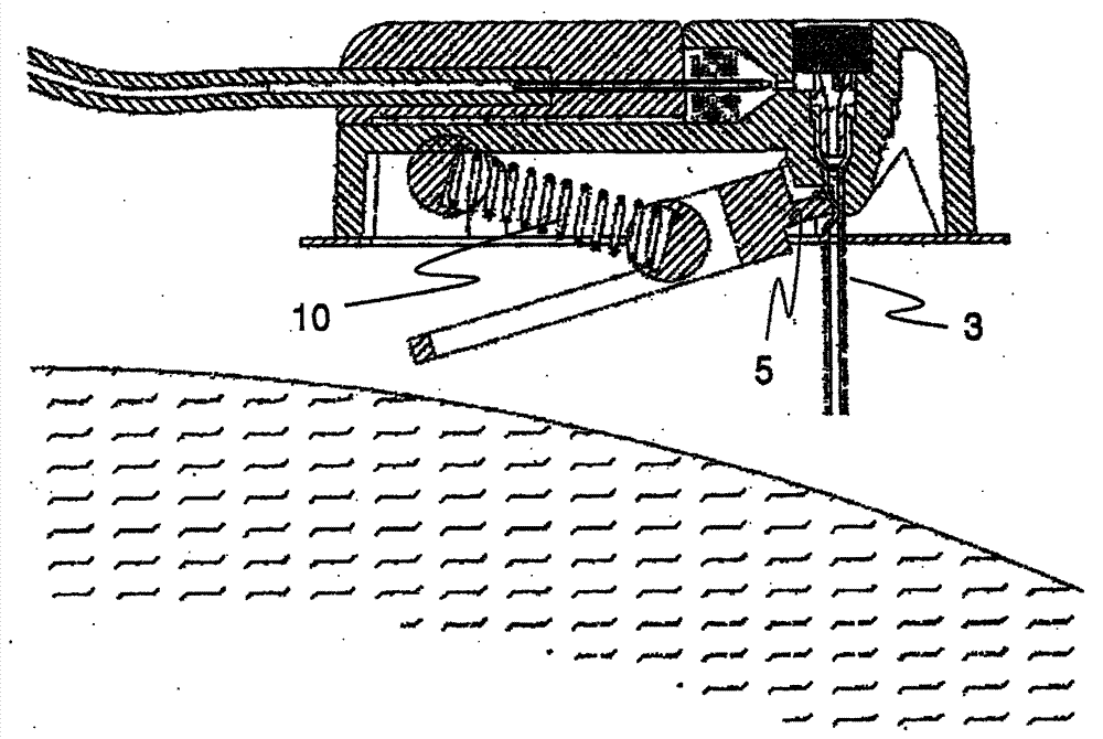
图5至图7分别是压缩凸轮的变体形式在其插入状态、非阻塞操作状态以及分离的阻塞状态的剖视图。 Figures 5 to 7 are cross-sectional views of a variant of the compression cam in its inserted state, its non-blocked operating state and its detached blocked state, respectively. the
图8是一个自闭合输液器的基于压缩的实施例的可滑动阻塞物的分解等轴测视图。 Figure 8 is an exploded isometric view of a slidable obstruction of a compression-based embodiment of a self-closing infusion set. the
图9和图10是图8所示输液器的剖视图,分别显示其阴塞和非阴塞状态,图11A和11B示出了第二可滑动阻塞物的变体形式的下侧在其阻塞和非阻塞状态的基于压缩的实施例。 Figures 9 and 10 are sectional views of the infusion set shown in Figure 8, respectively showing its female plug and non- female plug state, and Figures 11A and 11B show the lower side of the variant of the second slidable stopper in its blocked and non-yin plugged state. Compression-based implementation of non-blocking state. the
图12是自闭合输液器的基于压缩的实施例的第三可滑动阻塞物的变体形式的分解图。 Figure 12 is an exploded view of a third slidable stopper variation of the compression-based embodiment of the self-closing infusion set. the
图13A和13B是图12输液器的下侧示意图,其分别示出了阻塞和非阻塞状态。 Figures 13A and 13B are schematic views of the underside of the infusion set of Figure 12, showing occluded and non-occluded states, respectively. the
图14A和14B是自闭合输液器的基于压缩的实施例的第三可滑动阻塞物的变体形式示意图,其分别示出了在阻塞和非阻塞状态的一体式的铰链结构。 14A and 14B are schematic illustrations of a third slidable stopper variation of a compression-based embodiment of a self-closing infusion set showing the integral hinge structure in blocked and unobstructed states, respectively. the
图15至17是自闭合输液器的基于压缩的实施例的弹簧变体形式示意图,其分别示示出了它的插入状态,非阻塞操作状态和分离阻塞状态。 Figures 15 to 17 are schematic views of a spring variant of a compression-based embodiment of a self-closing infusion set, showing its inserted state, non-obstructed operating state, and de-occluded state, respectively. the
图18自闭合输液器的基于阻塞的实施例的第一形式的分解等轴测视图。 Figure 18 An exploded isometric view of a first form of the occlusion-based embodiment of the self-closing infusion set. the
图19是图18所示输液器的剖视图,示出了其操作及非阻塞状态。 Fig. 19 is a cross-sectional view of the infusion set shown in Fig. 18, showing its operation and unoccluded state. the
图20是图19所示输液器的近视剖视图。 Fig. 20 is a close-up sectional view of the infusion set shown in Fig. 19 . the
图21是如18所示输液器的组合,操作及非阻塞状态剖视图 Figure 21 is a combination of the infusion set shown in Figure 18, operation and non-blocking state sectional view
图22是图21的输液器的近视剖视图。 Fig. 22 is a close-up cross-sectional view of the infusion set in Fig. 21 . the
图23-25是输液器的基于阻塞的实施例的第二变体形式的剖视图,其分别示出了插入状态,操作的非阻塞状态以及阻塞状态。 23-25 are cross-sectional views of a second variant of the occlusion-based embodiment of the infusion set showing the inserted state, the operative non-occluded state, and the occluded state, respectively. the
图26和27是输液器的基于弯折的实施例,其分别示出了非阻塞操作状态和分离的阻塞状态。 Figures 26 and 27 are a bend-based embodiment of an infusion set showing a non-obstructed operating state and a detached occluded state, respectively. the
图28是一个自动药品输送系统的等轴测视图。 Figure 28 is an isometric view of an automated drug delivery system. the
优选实施例的描述 Description of the preferred embodiment
本发明是关于药物输送系统的一种机械、系统及对应的方法,用于当插管与病人分离时自动阻断流过输液器的液体。 The present invention relates to a mechanism, system and corresponding method of a drug delivery system for automatically blocking the flow of fluid through an infusion set when the cannula is separated from the patient. the
结合附图及描述可更好地理解本发明的各种实施原理及操作。本发明的机械将结合多个非限制性实例加以描述。三个基于阻塞方式的一般实施例将结合如下附图加以描述: Various implementation principles and operations of the present invention can be better understood with reference to the drawings and descriptions. The machine of the invention will be described with reference to several non-limiting examples. Three general embodiments based on blocking methods will be described in conjunction with the following figures:
第一个实施例将结合图1至7加以描述,该实施例限定了一个流动通 道,例如,通过施加外力使通道壁变形而完全阻断流动。 A first embodiment, which will be described with reference to Figures 1 to 7, defines a flow channel, for example, by applying an external force to deform the channel walls to completely block the flow. the
第二个实施例将结合图8~25介绍一个能充分阻塞流动通道的阻塞物。 A second embodiment will be described with reference to Figures 8-25 of a stopper that sufficiently blocks the flow path. the
第三实施例是使流动通道形状弯折或变形,该流动通道可以是插管的凸出部分,该实施例结合图26~27加以描述。 The third embodiment is to bend or deform the shape of the flow channel, which may be a protruding part of the cannula. This embodiment is described in conjunction with FIGS. 26-27 . the
尽管本发明描述了一些落入上述类别的具体的阻塞机构,但应注意本发明并不局限于这些实施例,通过如下描述可知,且在实施中可采用任何能有效地有选择地阻塞药物输送流动通道的某些部分的机械。 Although the present invention describes some specific blocking mechanisms that fall into the above categories, it should be noted that the present invention is not limited to these examples, as will be seen from the following description, and any mechanism effective to selectively block drug delivery may be used in practice. The mechanics of certain parts of the flow channel. the
在详述实施例之前,如上所述,应该知道所有的各种实施例都遵循与本发明的一个装置、系统和方法相对应的共同的操作原则。特别是像上面提到的,共同点在于,药物输送系统包括检测流动通道阻塞和产生向用户报警的结构,然而,可靠地检测因疏忽所造成的输液器从人体脱离则更为困难。为解决该问题,本发明提供一种改进的输液器,其在输液器脱离人体时,通过一个自闭塞机构来阻断液体流过输液器。该装置将难以检测的断开条件转变成对阻塞的易于检测的情况,因此有利于故障检测并及时向用户发出警报。 Before describing the embodiments in detail, as noted above, it should be known that all of the various embodiments follow common principles of operation corresponding to an apparatus, system and method of the present invention. In particular, as mentioned above, the commonality is that drug delivery systems include structures that detect flow channel obstruction and generate an alert to the user, however, it is more difficult to reliably detect inadvertent detachment of an infusion set from the body. To solve this problem, the present invention provides an improved infusion set, which uses a self-blocking mechanism to block the flow of liquid through the infusion set when the infusion set is detached from the human body. The device converts a difficult-to-detect disconnection condition into an easily detectable condition of obstruction, thus facilitating fault detection and timely alerting of the user. the
尽管描述了通过输液器的流体被完全阻塞的典型情况下的发明的最佳实施例,但应强调,产生部分阻塞的实施例也应在本发明范围内。不完全阻塞足以在药物输送流动通道引起背压的增加,这在许多药物输送系统中被作为一个须加以干涉的错误情况而加以检测,因而可用于本发明的环境。 While the preferred embodiment of the invention has been described for the typical situation in which fluid flow through the infusion set is completely obstructed, it should be emphasized that embodiments where partial obstruction occurs are also within the scope of the invention. Incomplete occlusion is sufficient to cause an increase in back pressure in the drug delivery flow path, which is detected in many drug delivery systems as an error condition requiring intervention, and thus can be used in the context of the present invention. the
应当指出,术语“断开”或“分离”是指输液器和人体之间失去接触,而足以影响插管的位置。因此,为了更清楚地说明,输液器和插管一起与人体完全失去接触的情况,以及输液器失去了接触而插管还插在人体上的两种情况是没有区别的,因为插管在输液器失去接触后不可避免地几乎是马上就会地会从病人身体上拔出。此外,输液器虽保持部分与人体接触,但不再为插管提供可靠的定位的情况也属于“断开”或“分离”。 It should be noted that the terms "disconnect" or "separate" refer to a loss of contact between the infusion set and the body sufficient to affect the position of the cannula. Therefore, to illustrate more clearly, there is no difference between the situation where the infusion set and the cannula are completely out of contact with the human body together, and the situation where the infusion set loses contact while the cannula is still inserted on the human body, because the cannula is in the infusion. It is inevitable that the device will be pulled out of the patient's body almost immediately after losing contact. In addition, the situation where the infusion set remains partially in contact with the body but no longer provides a reliable positioning for the cannula is also "disconnected" or "separated". the
此外,关于惯用语,术语“自闭合”涉及由多个元件的任何组合所产生的任何功能性,包括与输液器的内外联系而排除了需要人工干涉以阻塞输液器的液体流动。 Also, with regard to common usage, the term "self-closing" refers to any functionality resulting from any combination of elements, including internal and external communication with the infusion set, excluding the need for manual intervention to block fluid flow in the infusion set. the
在某些情况下,电的或其它的远程操作的流动阻塞装置可启动对输液器与人体断开的感测。 In some cases, an electrical or other remotely operated flow occlusion device may initiate the sensing of disconnection of the infusion set from the body. the
以下是对所有实施例都是同样的结构的一般性描述。 The following is a general description of the structure common to all embodiments. the
该自闭合输液器是一个使液体穿过皮肤的装置,包括一个将液体输送到皮肤内的具有管腔的插管;一个使输液器系到人体上以保持插管的插入皮肤的位置的固位装置;以及一个与固位装置和插管相连的自闭塞机构,使得当固位装置提供了输液器与人体的连接时,自闭塞机构保持在最初的非阻塞状态,且如果固位装置停止与人体连接时,自闭塞机构则呈现第二种状态,即自闭塞机构阻断液体流过插管。在下面的实施例中,很明显本发明是通过沿流动通道上的任一点阻塞液体流动通道来阻塞流体通过插管。 The self-closing infusion set is a device for passing liquid through the skin, including a cannula with a lumen for delivering the liquid into the skin; position device; and a self-occluding mechanism connected to the retaining device and the cannula such that when the retaining device provides connection to the infusion set with the body, the self-occluding mechanism remains in the initial non-obstructing state, and if the retaining device stops When connected to the human body, the self-occluding mechanism exhibits the second state, that is, the self-occluding mechanism blocks the flow of fluid through the cannula. In the following examples, it will be apparent that the present invention blocks fluid flow through the cannula by blocking the fluid flow path at any point along the flow path. the
参见图1~4,本发明的基于压缩的实施例的第一凸轮型,其包括一个插管3,一个阻塞液体流过插管3的压缩凸轮4,一个检测接近病人身体用的凸轮杠杆5,一个齿轮杠杆凹座6及一个使凸轮杠杆5偏置用的弹簧片7。压缩凸轮4可转动地装设于该单元的下侧,以便其有转动角自由度,使其能沿最初的方向转动到凸轮4压缩插管3的位置,并向相反方向转动以使凸轮4远离插管3.
Referring to Figures 1-4, the first cam type of the compression-based embodiment of the present invention comprises a cannula 3, a
凸轮杠杆5与压缩凸轮4相连接,以便使横杆在该单元下侧所限定的水平面的实质上的垂直运动转变成压缩凸轮4的转动。凸轮杠杆5设于压缩凸轮4上,使得当杠杆5置于凸轮杠杆凹座6内时,压缩凸轮4则远离插管3,且当凸轮杠杆5处于凸轮杠杆凹座6外侧时,压缩凸轮则用于阻塞插管3。弹簧7使凸轮杠杆5偏置,使得凸轮杠杆5的预置位置处在凸轮杠杆凹座6外侧。在输液单元的底部平面上设有粘性材料,以便将输液 单元固定到病人身体上。通过沿图4A、4B所示的顺时针方向或沿图2、、图3所示的逆时针方向转动压缩凸轮4,可压缩插管3。用于充分压缩插管的转动力矩的大小是插管3的壁变形的一项简单函数。
A
关于该装置的操作,在预置结构中,凸轮杠杆5凸出于凸轮杠杆凹座6,且压缩凸轮4处于其阻塞位置。当装上该单元时,病人身体将凸轮杠杆5推进凸轮杠杆凹座6内,并相应地使压缩凸轮4转动而远离插管3,使药物可以流动。插管3通过一插入针头插入病人体内,如清楚地显示在图6中的标号11。当该单元与病人身体分离时,凸轮杠杆5自由转动到其偏置位置,因而可将凸轮杠杆5转动到其施加力以压缩插管3的位置。而所产生的压力上升则启动了该系统的传统的压力响应报警。图5~7示出了基于压缩的实施例的第二种凸轮变体,包括一个枢接的阻塞插管3用的压缩杠杆5,一个使压缩杠杆5偏置于预置阻塞位置的压缩弹簧10。
Regarding the operation of the device, in the preset configuration, the
压缩弹簧10的设置角度相对于由该单元的底部所限定的水平面接近水平角,因而可变地偏置压缩元件5,以便当向插管3施加增力时对病人身体施加的力最小,当压缩杠杆到达最大转动角度时,可向插管施加最大压缩力。该功能是由于压缩元件5与弹簧10之间的角度增加而使弹簧10施加于压缩元件5的力的水平分量增加的结果。该特征确保压缩元件5既不会将输液器推离人体,又能有充分的转动力矩压缩插管3。应注意的是,可变偏置特征最好成为应用偏置元件来检测与病人身体失去接触的所有实施例的一部分。
The compression spring 10 is positioned at an angle close to the horizontal relative to the horizontal plane defined by the bottom of the unit, thereby variably biasing the
图8~10示出了一个可滑动阻塞物的基于压缩的实施例,其包括一输液器壳体20,可滑动阻塞物结构21,一个插管24,一个接近病人身体检测用的杠杆22,一个与杠杆22连接,用于将杠杆22的实质上的垂直运动转变为滑动阻塞物结构21的横向运动的连接轴26,一个将可滑动阻塞物结构21弹性地偏置到预置的阻塞位置的压缩弹簧23,该可滑动阻塞物结构21包括一个与连接轴26啮合的齿状接口25,一个弹簧导杆27,一个与 沿单元壳体20内壁的相应的唇状结构相连的唇状结构28,可滑动阻塞物结构21设置在输液器壳体20内,以便沿该单元的长度水平滑动。水平滑动性由与相应的唇状结构(未示出)相连的唇状结构28提供。压缩弹簧23设置在阻塞物结构21内,其将阻塞物结构21弹性地偏置于预定的阻塞位置。连接轴26与所连接的杠杆22置于阻塞物结构的齿状接口25内,以便将杠杆22的实质上的垂直运动转变为阻塞物结构21的横向运动,反之亦然。杠杆22的设置使得阻塞物结构21在其预定阻塞位置时,杠杆22相应地凸出于单元下侧之外,且当杠杆22转动进入单元下侧时,阻塞物结构21横向移动远离了插管24,使液体能自由流动。应注意,所有的可滑动阻塞物的实施例中,可滑动阻塞物沿着相应的唇部的滑动都适当地沿着单元壳体的内壁滑动。如上所述的装置的操作在每个实施例及其变体中都是类似的。
Figures 8-10 show a compression-based embodiment of a slidable stopper comprising an infusion set
图11示出了第二可滑动阻塞物的基于可压缩实施例的变体形式,其包括一个插管24,一个把可滑动阻塞物结构21接近病人身体变为接近插管的可折叠元件,一个可滑动阻塞物结构21和一个将可滑动阻塞物结构21偏置到预定的阻塞位置的压缩弹簧23。可折叠元件29包括两段顺序枢接的部分,用于确保部分折叠或充分伸展。可折叠元件29是可操作的,以便当可滑动阻塞物结构处于阻塞位置时其呈现为可折叠的,凸出的结构,并且当可滑动阻塞物结构21处于非阻塞位置时,其呈现为充分伸展,非凸出的结构。
Figure 11 shows a second slidable obstruction based variant of the compressible embodiment comprising a
图12~14示出了第三可滑动阻塞物基于可压缩实施例的变体形式,其采用了一体化的三段结构,以便在每个连接点形成一个有效的铰链。该变体形式包括一个压缩插管24用的可滑动压缩元件40,用于从接近病人身体的位置变到与可滑动压缩元件40对应位置的换位元件41和39,一个将压缩元件40偏置到预定的阻塞位置的压缩弹簧23。在连接到病人身体之前,压缩弹簧23将压缩元件40偏置,以沿着设置在单元壳体20内壁上的轨道滑动来阻塞插管24,且使得元件41绕一体连接点42转动,以便有一个角度接近绕远离单元的下侧的一体连接点43转动的元件39。这是假定当单元与病人身体脱离时的预定的阻塞位置。当连接到病人身体上时,元件反向转动而将压缩元件40滑入其非阻塞位置,而允许液体无限制地流过输液器。
Figures 12-14 show a third slidable stopper based on a compressible embodiment variant that uses an integrated three-section structure to form an effective hinge at each connection point. This variant includes a
图15~17示出了弹簧的基于可压缩实施例的变体形式,其采用弹簧片45作为阻塞元件。当输液器与病人身体脱离时,该弹簧片弹性地偏置以压迫并阻塞插管46,且当输液器连接到病人身体时,人体将弹簧推离插管,因此允许液体无限制地流过输液器。
Figures 15-17 show a variant of the spring based on a compressible embodiment, which employs a leaf spring 45 as the blocking element. When the infusion set is disconnected from the patient's body, the leaf spring is resiliently biased to compress and block the
图18~22示出了基于阻塞物的实施例的最初形式,其采用一个套状隔膜来阻塞液体流过输液器。该实施例包括一个插管56,一个压缩杠杆51,一个压缩弹簧56,一个循环毛细管54,一个套状隔膜53,一个系于隔膜53下边缘的阻塞物结构57,一个垂直的可移动的套环52,其用于调整隔膜53和隔膜孔55的高度,该套垂直设置于阻塞物结构57外部。环绕阻塞物的下边缘被扣紧到阻塞物结构57上且上边缘向下折叠,使得其内折叠的外表面向下延伸并扣紧到可移动的套环52。这种具有高度可调隔膜53的结构可通过使套环52向上或向下而被提高或降低。隔膜孔55形成于隔膜运动路线上部的输液器上。当隔膜处于其最高位置时,隔膜折叠具有隔膜孔的网片。
Figures 18-22 show an initial version of an occluder-based embodiment employing a sleeve-like septum to occlude fluid flow through the infusion set. This embodiment comprises a
通过输液器上的毛细管孔用作液体通道54。该毛细管孔与隔膜孔55相交,使得当隔膜处于其最低位置时,隔膜的上表面折叠为通道壁的底部。当隔膜处于其最高位置时,具有隔膜孔55的隔膜网则阻塞了液体通道。可移动的套环52可转动地与弹性杠杆51连接,以便向上移动套环52使输液器与病人身体相分离而阻塞流动通道54。
The capillary hole on the infusion set is used as the
图23~25示出了基于阻塞物的实施例的第二种变体形式,其采用一个阻塞物。该变体形式包括一个插管60,一个插管入口64,一个流动通道61,一个堵塞插管入口64用的塞子62,一个为62提供垂直移动性的可移动塞子支架63。塞子62由密封材料制成,用于堵塞插管入口64,以阻断通过插管的液体通道。塞子62装在垂直向下延伸的塞子支架63上,使得当其底端置于病人身体上时且当输液器连接到人体上时,支撑塞子62的支架使塞子62处在插管入口64的上方,因而使液体可无限制地流过插管。塞子支架63一失去与人体接触就会垂直向下移动,并因此使所带的塞子降低到插管入口64,以阻塞液体流动通道。支架63通过一个弹簧(图中未示出)向下移动,预定的位置将是阻塞位置。
Figures 23-25 show a second variant of the stopper-based embodiment using one stopper. This variant includes a
图26~27示出了一个自弯折实施例,其采用了一个自弯折插管70,它可分别在非阻塞和阻塞状态操作。插管70在非弯折状态时插入,并向上与病人身体相分离,使得弯折结构在连接弯折点的插管的两部分之间形成一实质上的90度角,以充分阻塞液体通道。该功能是通过将插管70由形状记忆高分子材料制成而实现的,通过该形状记忆高分子材料可建立一个永久弯折阻塞结构和一个实质上是直的临时操作结构。在插入病人身体后,人体的自然热量唤醒了潜伏的弯折结构,并由病人身体抑制采用这种结构。只要从人体上一移去插管70,就可免除采取弯折阻塞结构。作为选择,该功能也可通过将插管70形成一弯折结构来实现,通过一插入针头,该弯折结构具有充分的灵活性由弯曲操作结构成为拉直操作结构。
Figures 26-27 illustrate a self-deflecting embodiment employing a self-deflecting
这种弯折实施例的一种变体形式采用了一个压缩机械,如图11A、11B所示,该压缩机械产生在一个平坦的表面与一个尖锐边缘之间。这种压缩几何结构使得插管被急剧弯曲,因而阻塞了液体通道。 A variation of this bent embodiment uses a compression mechanism, as shown in Figures 11A, 11B, that is created between a flat surface and a sharp edge. This compressed geometry causes the cannula to be bent sharply, thereby blocking the passage of fluid. the
图28示出了本发明的药物输送装置。如图示,该系统包括一个与输液器76连接的药物泵75,输液器76则通过一个粘接片77固定到病人身体上。拉环78则便于拆卸。
Figure 28 shows a drug delivery device of the present invention. As shown in the figure, the system includes a
应理解上述描述只是举例,许多其它可能的实施例均在本发明的权利要求所限定的范围内。 It should be understood that the foregoing description is by way of example only, and that many other possible embodiments are within the scope of the invention as defined by the appended claims. the
Claims (8)
Applications Claiming Priority (3)
| Application Number | Priority Date | Filing Date | Title |
|---|---|---|---|
| US91707507P | 2007-05-10 | 2007-05-10 | |
| US60/917,075 | 2007-05-10 | ||
| PCT/IL2008/000647 WO2008139464A1 (en) | 2007-05-10 | 2008-05-11 | Infusion set self-occlusion mechanism |
Publications (2)
| Publication Number | Publication Date |
|---|---|
| CN101730555A CN101730555A (en) | 2010-06-09 |
| CN101730555B true CN101730555B (en) | 2012-11-07 |
Family
ID=39720100
Family Applications (1)
| Application Number | Title | Priority Date | Filing Date |
|---|---|---|---|
| CN2008800151752A Expired - Fee Related CN101730555B (en) | 2007-05-10 | 2008-05-11 | Infusion set self-occlusion mechanism |
Country Status (7)
| Country | Link |
|---|---|
| US (2) | US7951122B2 (en) |
| EP (1) | EP2144646A1 (en) |
| JP (1) | JP5328767B2 (en) |
| KR (1) | KR20100014561A (en) |
| CN (1) | CN101730555B (en) |
| IL (1) | IL200840A (en) |
| WO (1) | WO2008139464A1 (en) |
Families Citing this family (42)
| Publication number | Priority date | Publication date | Assignee | Title |
|---|---|---|---|---|
| EP2037999B1 (en) | 2006-07-07 | 2016-12-28 | Proteus Digital Health, Inc. | Smart parenteral administration system |
| JP4994775B2 (en) | 2006-10-12 | 2012-08-08 | 日本コヴィディエン株式会社 | Needle point protector |
| WO2009055733A1 (en) | 2007-10-25 | 2009-04-30 | Proteus Biomedical, Inc. | Fluid transfer port information system |
| US8419638B2 (en) | 2007-11-19 | 2013-04-16 | Proteus Digital Health, Inc. | Body-associated fluid transport structure evaluation devices |
| US8986253B2 (en) | 2008-01-25 | 2015-03-24 | Tandem Diabetes Care, Inc. | Two chamber pumps and related methods |
| US8408421B2 (en) | 2008-09-16 | 2013-04-02 | Tandem Diabetes Care, Inc. | Flow regulating stopcocks and related methods |
| EP2334234A4 (en) | 2008-09-19 | 2013-03-20 | Tandem Diabetes Care Inc | Solute concentration measurement device and related methods |
| US8230744B2 (en) * | 2009-05-06 | 2012-07-31 | Cequr Sa | Low-dead volume microfluidic circuit and methods |
| US20100282766A1 (en) * | 2009-05-06 | 2010-11-11 | Heiko Arndt | Low-Dead Volume Microfluidic Component and Method |
| US20110152770A1 (en) | 2009-07-30 | 2011-06-23 | Tandem Diabetes Care, Inc. | Infusion pump system with disposable cartridge having pressure venting and pressure feedback |
| BR112012019212A2 (en) | 2010-02-01 | 2017-06-13 | Proteus Digital Health Inc | data collection system |
| JP5330609B2 (en) | 2010-02-01 | 2013-10-30 | プロテウス デジタル ヘルス, インコーポレイテッド | Data collection system on two wrists |
| CN102985129B (en) * | 2010-06-24 | 2015-08-05 | 甘布罗伦迪亚股份公司 | Blood access device |
| WO2012032411A2 (en) | 2010-09-07 | 2012-03-15 | Tecpharma Licensing Ag | Automatic injection device |
| EP2517751B8 (en) | 2011-04-27 | 2018-02-28 | Kpr U.S., Llc | Safety IV catheter assemblies |
| US8628497B2 (en) | 2011-09-26 | 2014-01-14 | Covidien Lp | Safety catheter |
| US8715250B2 (en) | 2011-09-26 | 2014-05-06 | Covidien Lp | Safety catheter and needle assembly |
| EP2766074B1 (en) | 2011-10-14 | 2020-04-08 | Kpr U.S., Llc | Safety iv catheter assembly |
| US9180242B2 (en) | 2012-05-17 | 2015-11-10 | Tandem Diabetes Care, Inc. | Methods and devices for multiple fluid transfer |
| US9173998B2 (en) | 2013-03-14 | 2015-11-03 | Tandem Diabetes Care, Inc. | System and method for detecting occlusions in an infusion pump |
| US10279105B2 (en) | 2013-12-26 | 2019-05-07 | Tandem Diabetes Care, Inc. | System and method for modifying medicament delivery parameters after a site change |
| WO2015156850A1 (en) | 2014-04-11 | 2015-10-15 | Hemotek Medical Incorporated | Systems and methods for automatic termination of flow due to needle dislodgement |
| US20170124285A1 (en) | 2014-06-03 | 2017-05-04 | Amgen Inc. | Devices and methods for assisting a user of a drug delivery device |
| US10668227B2 (en) | 2014-09-15 | 2020-06-02 | Sanofi | Skin-attachable drug injection device with detachment sensor |
| WO2016100055A1 (en) | 2014-12-19 | 2016-06-23 | Amgen Inc. | Drug delivery device with live button or user interface field |
| JP6716566B2 (en) * | 2014-12-19 | 2020-07-01 | アムジエン・インコーポレーテツド | Drug delivery device with proximity sensor |
| US10583245B2 (en) * | 2015-02-17 | 2020-03-10 | Amgen Inc. | Drug delivery device with vacuum assisted securement and/or feedback |
| WO2017190024A1 (en) * | 2016-04-29 | 2017-11-02 | Naya Health, Inc. | Hydraulic pumping system for expression of breast milk |
| CN110418656B (en) | 2016-12-21 | 2022-06-17 | 赫莫泰克医疗公司 | Needle safety system |
| EP4306146A3 (en) * | 2017-09-25 | 2024-01-24 | Insulet Corporation | Pre-filled cartridge-based drug delivery device |
| CN114642790B (en) * | 2017-10-16 | 2023-10-03 | 贝克顿·迪金森公司 | Tube clamping device for a drug delivery device |
| DE102018108293A1 (en) * | 2018-04-09 | 2019-10-10 | B. Braun Avitum Ag | Access cannula with locking device |
| CN117045897A (en) * | 2018-05-03 | 2023-11-14 | 赫莫泰克医疗公司 | Needle safety system |
| US11213460B2 (en) | 2018-09-19 | 2022-01-04 | Vesco Medical Llc | Connectors for infusion pump feeding sets |
| US12539361B2 (en) | 2019-02-22 | 2026-02-03 | Deka Products Limited Partnership | Infusion set and inserter assembly apparatuses, systems, and methods |
| CN114502216B (en) | 2019-08-14 | 2025-04-04 | 赫莫泰克医疗公司 | Needle safety system |
| KR102477255B1 (en) * | 2020-09-10 | 2022-12-14 | 이오플로우(주) | Method, apparatus and computer program product for determining the occurrence of occulusion in the inlet of a drug injection device |
| CN112827009B (en) * | 2021-02-20 | 2022-11-25 | 山东第一医科大学附属省立医院(山东省立医院) | Embedded gastroenterostomy nutrition input port |
| USD1013864S1 (en) | 2021-08-26 | 2024-02-06 | Deka Products Limited Partnership | Fluid administration apparatus assembly |
| USD1057941S1 (en) | 2022-08-26 | 2025-01-14 | Deka Products Limited Partnership | Patient care assembly component |
| USD1043976S1 (en) | 2022-08-26 | 2024-09-24 | Deka Products Limited Partnership | Fluid transfer connector |
| USD1090862S1 (en) | 2022-08-26 | 2025-08-26 | Deka Products Limited Partnership | Adhering assembly for medical devices and the like |
Citations (3)
| Publication number | Priority date | Publication date | Assignee | Title |
|---|---|---|---|---|
| US4874377A (en) * | 1988-05-26 | 1989-10-17 | Davis Newgard Revocable Family Living Trust | Self-occluding intravascular cannula assembly |
| US6126637A (en) * | 1998-04-15 | 2000-10-03 | Science Incorporated | Fluid delivery device with collapsible needle cover |
| CN1556716A (en) * | 2001-02-22 | 2004-12-22 | ���Ͽع�����˾ | Modular infusion devices and methods |
Family Cites Families (4)
| Publication number | Priority date | Publication date | Assignee | Title |
|---|---|---|---|---|
| US5968011A (en) * | 1997-06-20 | 1999-10-19 | Maersk Medical A/S | Subcutaneous injection set |
| US7147615B2 (en) * | 2001-06-22 | 2006-12-12 | Baxter International Inc. | Needle dislodgement detection |
| US7165568B2 (en) * | 2003-05-29 | 2007-01-23 | Axial Technologies Limited | Rotating valve assembly |
| US20070250007A1 (en) * | 2006-04-23 | 2007-10-25 | Nilimedix Ltd. | Drug Delivery Device With Air Pressure Spring And Safety Valve |
-
2008
- 2008-05-11 CN CN2008800151752A patent/CN101730555B/en not_active Expired - Fee Related
- 2008-05-11 KR KR1020097019938A patent/KR20100014561A/en not_active Withdrawn
- 2008-05-11 JP JP2010507059A patent/JP5328767B2/en not_active Expired - Fee Related
- 2008-05-11 EP EP08738346A patent/EP2144646A1/en not_active Withdrawn
- 2008-05-11 WO PCT/IL2008/000647 patent/WO2008139464A1/en not_active Ceased
- 2008-05-12 US US12/118,786 patent/US7951122B2/en not_active Expired - Fee Related
-
2009
- 2009-09-09 IL IL20084009A patent/IL200840A/en not_active IP Right Cessation
-
2011
- 2011-05-26 US US13/116,033 patent/US8439879B2/en not_active Expired - Fee Related
Patent Citations (3)
| Publication number | Priority date | Publication date | Assignee | Title |
|---|---|---|---|---|
| US4874377A (en) * | 1988-05-26 | 1989-10-17 | Davis Newgard Revocable Family Living Trust | Self-occluding intravascular cannula assembly |
| US6126637A (en) * | 1998-04-15 | 2000-10-03 | Science Incorporated | Fluid delivery device with collapsible needle cover |
| CN1556716A (en) * | 2001-02-22 | 2004-12-22 | ���Ͽع�����˾ | Modular infusion devices and methods |
Also Published As
| Publication number | Publication date |
|---|---|
| JP2010526578A (en) | 2010-08-05 |
| WO2008139464A1 (en) | 2008-11-20 |
| US20110224601A1 (en) | 2011-09-15 |
| US7951122B2 (en) | 2011-05-31 |
| EP2144646A1 (en) | 2010-01-20 |
| US8439879B2 (en) | 2013-05-14 |
| IL200840A (en) | 2013-04-30 |
| CN101730555A (en) | 2010-06-09 |
| IL200840A0 (en) | 2010-05-17 |
| JP5328767B2 (en) | 2013-10-30 |
| KR20100014561A (en) | 2010-02-10 |
| US20080281276A1 (en) | 2008-11-13 |
Similar Documents
| Publication | Publication Date | Title |
|---|---|---|
| CN101730555B (en) | Infusion set self-occlusion mechanism | |
| CN103282010B (en) | For the anti-free flow of intestinal supply pump | |
| CN102065932B (en) | Anti-free-flow mechanism for enteral feeding pumps | |
| EP1778338B1 (en) | Automatic clamp apparatus for iv infusion sets used in pump devices | |
| US7815612B2 (en) | Apparatus and method for preventing free flow in an infusion line | |
| US8491543B2 (en) | Automatic safety occluder | |
| EP2621560B1 (en) | Anti free-flow occluder and priming actuator pad | |
| EP0900106A1 (en) | Pinch clip occluder for infusion sets | |
| CN111601629A (en) | Liquid flow regulating device | |
| HK1182972A (en) | Anti free-flow occluder and priming actuator pad | |
| HK1182972B (en) | Anti free-flow occluder and priming actuator pad |
Legal Events
| Date | Code | Title | Description |
|---|---|---|---|
| C06 | Publication | ||
| PB01 | Publication | ||
| C10 | Entry into substantive examination | ||
| SE01 | Entry into force of request for substantive examination | ||
| C14 | Grant of patent or utility model | ||
| GR01 | Patent grant | ||
| C17 | Cessation of patent right | ||
| CF01 | Termination of patent right due to non-payment of annual fee |
Granted publication date: 20121107 Termination date: 20130511 |