CN101703414B - Surgical clip applier and method of assembly - Google Patents
Surgical clip applier and method of assembly Download PDFInfo
- Publication number
- CN101703414B CN101703414B CN2009101675681A CN200910167568A CN101703414B CN 101703414 B CN101703414 B CN 101703414B CN 2009101675681 A CN2009101675681 A CN 2009101675681A CN 200910167568 A CN200910167568 A CN 200910167568A CN 101703414 B CN101703414 B CN 101703414B
- Authority
- CN
- China
- Prior art keywords
- passage
- applicator
- clip
- motion
- push rod
- Prior art date
- Legal status (The legal status is an assumption and is not a legal conclusion. Google has not performed a legal analysis and makes no representation as to the accuracy of the status listed.)
- Expired - Fee Related
Links
- 238000000034 method Methods 0.000 title description 19
- 230000033001 locomotion Effects 0.000 claims abstract description 143
- 230000007246 mechanism Effects 0.000 claims description 39
- 230000003321 amplification Effects 0.000 claims description 27
- 238000003199 nucleic acid amplification method Methods 0.000 claims description 27
- 230000005540 biological transmission Effects 0.000 claims description 6
- 238000006073 displacement reaction Methods 0.000 claims description 5
- 238000013519 translation Methods 0.000 description 43
- 230000014616 translation Effects 0.000 description 43
- 230000001133 acceleration Effects 0.000 description 18
- 230000015572 biosynthetic process Effects 0.000 description 12
- 230000032258 transport Effects 0.000 description 8
- 238000010586 diagram Methods 0.000 description 6
- ZZUFCTLCJUWOSV-UHFFFAOYSA-N furosemide Chemical compound C1=C(Cl)C(S(=O)(=O)N)=CC(C(O)=O)=C1NCC1=CC=CO1 ZZUFCTLCJUWOSV-UHFFFAOYSA-N 0.000 description 6
- 230000008569 process Effects 0.000 description 6
- 230000004913 activation Effects 0.000 description 5
- 230000000295 complement effect Effects 0.000 description 5
- 238000012797 qualification Methods 0.000 description 5
- 230000002792 vascular Effects 0.000 description 4
- 210000005056 cell body Anatomy 0.000 description 3
- 230000000694 effects Effects 0.000 description 3
- 230000001737 promoting effect Effects 0.000 description 3
- 230000000284 resting effect Effects 0.000 description 3
- 230000003213 activating effect Effects 0.000 description 2
- 238000005516 engineering process Methods 0.000 description 2
- 239000000463 material Substances 0.000 description 2
- 230000004048 modification Effects 0.000 description 2
- 238000012986 modification Methods 0.000 description 2
- 230000007115 recruitment Effects 0.000 description 2
- 229910000831 Steel Inorganic materials 0.000 description 1
- RTAQQCXQSZGOHL-UHFFFAOYSA-N Titanium Chemical compound [Ti] RTAQQCXQSZGOHL-UHFFFAOYSA-N 0.000 description 1
- 238000005452 bending Methods 0.000 description 1
- 230000008859 change Effects 0.000 description 1
- 230000001143 conditioned effect Effects 0.000 description 1
- 230000008602 contraction Effects 0.000 description 1
- 230000006870 function Effects 0.000 description 1
- 239000004973 liquid crystal related substance Substances 0.000 description 1
- 230000004807 localization Effects 0.000 description 1
- 238000012423 maintenance Methods 0.000 description 1
- 230000014759 maintenance of location Effects 0.000 description 1
- 238000006386 neutralization reaction Methods 0.000 description 1
- 230000002265 prevention Effects 0.000 description 1
- 230000001105 regulatory effect Effects 0.000 description 1
- 230000004044 response Effects 0.000 description 1
- 230000003068 static effect Effects 0.000 description 1
- 239000010959 steel Substances 0.000 description 1
- 229910052719 titanium Inorganic materials 0.000 description 1
- 239000010936 titanium Substances 0.000 description 1
Images


Classifications
-
- A—HUMAN NECESSITIES
- A61—MEDICAL OR VETERINARY SCIENCE; HYGIENE
- A61B—DIAGNOSIS; SURGERY; IDENTIFICATION
- A61B17/00—Surgical instruments, devices or methods
- A61B17/12—Surgical instruments, devices or methods for ligaturing or otherwise compressing tubular parts of the body, e.g. blood vessels or umbilical cord
- A61B17/128—Surgical instruments, devices or methods for ligaturing or otherwise compressing tubular parts of the body, e.g. blood vessels or umbilical cord for applying or removing clamps or clips
- A61B17/1285—Surgical instruments, devices or methods for ligaturing or otherwise compressing tubular parts of the body, e.g. blood vessels or umbilical cord for applying or removing clamps or clips for minimally invasive surgery
-
- A—HUMAN NECESSITIES
- A61—MEDICAL OR VETERINARY SCIENCE; HYGIENE
- A61B—DIAGNOSIS; SURGERY; IDENTIFICATION
- A61B34/00—Computer-aided surgery; Manipulators or robots specially adapted for use in surgery
- A61B34/70—Manipulators specially adapted for use in surgery
- A61B34/76—Manipulators having means for providing feel, e.g. force or tactile feedback
-
- A—HUMAN NECESSITIES
- A61—MEDICAL OR VETERINARY SCIENCE; HYGIENE
- A61B—DIAGNOSIS; SURGERY; IDENTIFICATION
- A61B17/00—Surgical instruments, devices or methods
- A61B2017/00017—Electrical control of surgical instruments
- A61B2017/00115—Electrical control of surgical instruments with audible or visual output
-
- A—HUMAN NECESSITIES
- A61—MEDICAL OR VETERINARY SCIENCE; HYGIENE
- A61B—DIAGNOSIS; SURGERY; IDENTIFICATION
- A61B17/00—Surgical instruments, devices or methods
- A61B2017/00367—Details of actuation of instruments, e.g. relations between pushing buttons, or the like, and activation of the tool, working tip, or the like
- A61B2017/00407—Ratchet means
-
- A—HUMAN NECESSITIES
- A61—MEDICAL OR VETERINARY SCIENCE; HYGIENE
- A61B—DIAGNOSIS; SURGERY; IDENTIFICATION
- A61B17/00—Surgical instruments, devices or methods
- A61B2017/0046—Surgical instruments, devices or methods with a releasable handle; with handle and operating part separable
- A61B2017/00464—Surgical instruments, devices or methods with a releasable handle; with handle and operating part separable for use with different instruments
-
- A—HUMAN NECESSITIES
- A61—MEDICAL OR VETERINARY SCIENCE; HYGIENE
- A61B—DIAGNOSIS; SURGERY; IDENTIFICATION
- A61B17/00—Surgical instruments, devices or methods
- A61B2017/00526—Methods of manufacturing
-
- A—HUMAN NECESSITIES
- A61—MEDICAL OR VETERINARY SCIENCE; HYGIENE
- A61B—DIAGNOSIS; SURGERY; IDENTIFICATION
- A61B17/00—Surgical instruments, devices or methods
- A61B17/28—Surgical forceps
- A61B17/29—Forceps for use in minimally invasive surgery
- A61B17/2909—Handles
- A61B2017/2912—Handles transmission of forces to actuating rod or piston
- A61B2017/2923—Toothed members, e.g. rack and pinion
-
- A—HUMAN NECESSITIES
- A61—MEDICAL OR VETERINARY SCIENCE; HYGIENE
- A61B—DIAGNOSIS; SURGERY; IDENTIFICATION
- A61B90/00—Instruments, implements or accessories specially adapted for surgery or diagnosis and not covered by any of the groups A61B1/00 - A61B50/00, e.g. for luxation treatment or for protecting wound edges
- A61B90/03—Automatic limiting or abutting means, e.g. for safety
- A61B2090/038—Automatic limiting or abutting means, e.g. for safety during shipment
-
- A—HUMAN NECESSITIES
- A61—MEDICAL OR VETERINARY SCIENCE; HYGIENE
- A61B—DIAGNOSIS; SURGERY; IDENTIFICATION
- A61B90/00—Instruments, implements or accessories specially adapted for surgery or diagnosis and not covered by any of the groups A61B1/00 - A61B50/00, e.g. for luxation treatment or for protecting wound edges
- A61B90/08—Accessories or related features not otherwise provided for
- A61B2090/0803—Counting the number of times an instrument is used
-
- A—HUMAN NECESSITIES
- A61—MEDICAL OR VETERINARY SCIENCE; HYGIENE
- A61B—DIAGNOSIS; SURGERY; IDENTIFICATION
- A61B90/00—Instruments, implements or accessories specially adapted for surgery or diagnosis and not covered by any of the groups A61B1/00 - A61B50/00, e.g. for luxation treatment or for protecting wound edges
- A61B90/08—Accessories or related features not otherwise provided for
- A61B2090/0807—Indication means
- A61B2090/0811—Indication means for the position of a particular part of an instrument with respect to the rest of the instrument, e.g. position of the anvil of a stapling instrument
-
- A—HUMAN NECESSITIES
- A61—MEDICAL OR VETERINARY SCIENCE; HYGIENE
- A61B—DIAGNOSIS; SURGERY; IDENTIFICATION
- A61B90/00—Instruments, implements or accessories specially adapted for surgery or diagnosis and not covered by any of the groups A61B1/00 - A61B50/00, e.g. for luxation treatment or for protecting wound edges
- A61B90/08—Accessories or related features not otherwise provided for
- A61B2090/0814—Preventing re-use
-
- Y—GENERAL TAGGING OF NEW TECHNOLOGICAL DEVELOPMENTS; GENERAL TAGGING OF CROSS-SECTIONAL TECHNOLOGIES SPANNING OVER SEVERAL SECTIONS OF THE IPC; TECHNICAL SUBJECTS COVERED BY FORMER USPC CROSS-REFERENCE ART COLLECTIONS [XRACs] AND DIGESTS
- Y10—TECHNICAL SUBJECTS COVERED BY FORMER USPC
- Y10T—TECHNICAL SUBJECTS COVERED BY FORMER US CLASSIFICATION
- Y10T29/00—Metal working
- Y10T29/49—Method of mechanical manufacture
- Y10T29/49826—Assembling or joining
Landscapes
- Health & Medical Sciences (AREA)
- Surgery (AREA)
- Life Sciences & Earth Sciences (AREA)
- Engineering & Computer Science (AREA)
- Heart & Thoracic Surgery (AREA)
- Nuclear Medicine, Radiotherapy & Molecular Imaging (AREA)
- Biomedical Technology (AREA)
- Medical Informatics (AREA)
- Molecular Biology (AREA)
- Animal Behavior & Ethology (AREA)
- General Health & Medical Sciences (AREA)
- Public Health (AREA)
- Veterinary Medicine (AREA)
- Vascular Medicine (AREA)
- Reproductive Health (AREA)
- Robotics (AREA)
- Surgical Instruments (AREA)
Abstract
Surgical clip appliers are provided and include a channel assembly extending distally from a housing; a clip carrier disposed within said channel assembly and defining a channel and a plurality of windows therein; a plurality of clips slidably disposed within said channel of said clip carrier; a wedge plate reciprocally disposed within said channel assembly, said wedge plate being operatively connected to said handles and including a plurality of apertures formed along a length thereof; and a clip follower slidably disposed within said channel of said clip carrier and disposed proximally of said plurality of clips, said clip follower being configured and adapted for selective engagement with said windows of said clip carrier and said apertures of said wedge plate. The clip follower is configured and adapted to urge said plurality of clips, in a distal direction relative to said clip carrier, upon reciprocal movement of said wedge plate.
Description
The cross reference of related application
It is 61/091,485 U.S. Provisional Application No. interests that the application requires in the serial number that on August 25th, 2008 submitted to, and its full content is incorporated herein by reference.
Technical field
The application relates to operating theater instruments and their assemble method, and relates in particular to and have a plurality of clips during the operation technique clip is being applied to operation applicator on soma and the vascular and their assemble method.
Background technology
Operation applicator is known and by providing the system of selection that the tradition of soma and vascular is sewed up more popular between the surgeon in the art.In Green people's such as (Green) the patent No. is that 5,030,226 United States Patent (USP) and Bai Banke three generations people's such as (Burbank III) the patent No. is to disclose typical apparatus in 5,431,668 the United States Patent (USP).These apparatuses are provided with a plurality of clips usually, and these clips are stored in the apparatus and when the open and close handle of the proximal end of apparatus, these clips one after the other are fed in the jaw mechanism of the far-end of apparatus.Along with the handle closure, jaw is closed so that be positioned at clip distortion between the jaw member, and along with jaw is opened to unclamp the clip of distortion, new clip is fed into the position between the jaw from sequence.Repeat this process and obtained application up to all clips in the clip sequence.
Typically, can use relatively little, the different size in relatively in the by the time big relatively scope and/or the operation applicator of ratio.Normally, the operation applicator of each special size comprises different parts.Similarly, the method for the operation applicator of assembling different size is also different to another kind of size from a kind of size.
Therefore, must teach different program of technical staff and operation operation applicator with the assembling different size.Therefore, when the technical staff was used for a kind of assembly operation of operation applicator of size the assembly operation of operation applicator of another kind of size mistakenly, the degree that makes a mistake in the operation applicator of assembling different size may improve.
Therefore, need have the apparatus that is used to apply the operation clip of gang's different size, described apparatus is assembled to another kind of size in an identical manner from a kind of size.
Equally, in order to enhance productivity, need to exist the unified method of the apparatus of assembling each different size.
Summary of the invention
The application relates to and has a plurality of clips and be used for during the operation technique clip being applied to operation applicator on soma and the vascular and their assemble method.
According to scheme of the present disclosure, be provided with a kind of operation applicator, described operation applicator comprises: housing; At least one handle, it is pivotably connected to described housing; Channel components, it extends from described housing; Clip carrier (clip carrier), it is arranged in the described channel components and qualification passage and a plurality of window wherein; A plurality of clips, it is slidably disposed in the described passage of described clip carrier; Clapboard, it can be arranged in the described channel components with moving back and forth, and described clapboard is operably connected on the described handle and comprises a plurality of holes that form along its length; And clip follower (clipfollower), it is slidably disposed in the described passage of described clip carrier and is positioned at the proximal position place of described a plurality of clips, and described clip follower is configured and is suitable for optionally engaging the described hole of the described window and the described clapboard of described clip carrier.The clip follower is configured and is suitable for distad promoting described a plurality of clip with respect to described clip carrier when described clapboard moves back and forth.
The clip follower can be constructed to engage clapboard and in clapboard distal motion during translation distad, and can be constructed to the engaging clip carrier and stop its proximal motion when the translation of clapboard proximad.
Applicator may further include the jaw assembly, and described jaw assembly comprises an end extended a pair of jaw opposite with described housing from described channel components.The jaw assembly can be suitable for holding clip in wherein and can operate to realize the formation of clip in response to the motion of described handle.
Applicator may further include the clip push rod (clip pusher bar) at least one that can be positioned at described housing and described channel components with moving back and forth.Push rod can have first end that is operably connected to described at least one handle and second end that limits pusher (pusher).Push rod can along with described at least one handle first party move upward primary quantity and towards the motion of described jaw so that move farthest side clip between the described jaw.Push rod can be configured and be suitable for along with described at least one handle described first party move upward additional quantity and towards the motion of described housing so that the described pusher after moving farthest side clip in described a plurality of clips.
Applicator may further include motion amplification system (motion multiplier system), described motion amplifying system constructed is for making push rod distal motion recruitment when the handle initial activation, and be constructed to be right after after the initial activation of handle proximad mobile putter and clapboard.
But applicator can further include translation ground and is slidably disposed on driving passage at least one of described housing and described channel components.Driving passage can have, be operably connected in the described handle at least one first end and be configured and be sized to and optionally engage second end of described a pair of jaw with the closure that realizes described a pair of jaw.Driving passage can activated on first direction and described second bring in closed described jaw towards described jaw assembly motion so that move it facing to described jaw along with described handle.Drive passage along with described handle second party move upward and away from described jaw so that its described second end allows described jaw to open away from described jaw.
Applicator may further include the pivotal arm that is operably connected to described clapboard and described driving passage.During the distal movement of described driving passage, the rotation of described pivotal arm can cause the proximal movement of described clapboard.
Applicator may further include the motion amplification system, and the motion amplification system comprises: bellcrank gear (bell crank gear), and it is supported in the housing pivotly and is pivotably connected to push rod; Quicken tooth bar (accelarator rack), it is supported in the housing slidably and is operably connected to the bellcrank gear; And biasing member, it makes the driving passage interconnection with the acceleration tooth bar.The distally translation that drives passage can cause the distally translation of quickening tooth bar via biasing member.The distally translation of quickening tooth bar can cause that first of bellcrank gear rotates and the distally translation of push rod.
The bellcrank gear can comprise that wherein elongated slot is held the boss operationally relevant with push rod (boss) slidably from its radially extended arm and the elongated slot that forms arm.
Applicator may further include reversing of motion mechanism (motion reversingmechanism), and reversing of motion mechanism is operably connected to described driving passage and described clapboard and can optionally engages with described push rod.During the described distally translation of described driving passage, the rotation of described reversing of motion mechanism can cause the proximal movement of described clapboard and described push rod.
Applicator may further include ratchet mechanism, and described ratchet mechanism comprises: tooth bar, and it has a plurality of ratchets and related with described driving passage; And ratchet pawl, it has at least one tooth and is disposed in the position that optionally engages described tooth bar.Ratchet pawl can be biased to described tooth bar and engage.Along with described driving passage longitudinally moves back and forth, described a plurality of teeth can be crossed described ratchet pawl.Ratchet pawl can prevent described driving passage unintentional returning before described at least one handle activates fully.
Applicator may further include the dead lock (lockout) in the far-end that is arranged on described channel components.Dead lock can be activated by described clip follower when described applicator is discharged at last clip.Dead lock can be promoted extending across the path of described driving passage by described clip follower, thereby prevents described driving passage distal motion.
Applicator may further include the counting mechanism at least one that is supported on described housing and described channel components.Counting mechanism can be configured and be suitable for showing the variation in described applicator when described handle activates at every turn.
Driving passage can be configured and be sized at least in part around described jaw and described clapboard.Driving passage can comprise and run through the strap (strap) that its far-end is used for described jaw and described clapboard are remained on described driving passage.
According to another scheme of the present disclosure, be provided with operation applicator, described operation applicator comprises: housing; At least one handle, it is pivotably connected to the opposition side of housing; Channel components, it is fixed to housing and extends from housing; A pair of jaw, it is supported on the far-end of channel components and goes out from the remote extension of channel components; The clip carrier, it is arranged in the described channel components and limits passage; A plurality of clips, it is slidably disposed in the described passage of described clip carrier; The clip follower, its proximal position place at described a plurality of clips is slidably disposed in the described passage of described clip carrier; Drive passage, but be arranged on to its translation at least one of described housing and described channel components, described driving passage has first end and second end, described first end is operably connected in the described handle at least one, and described second end is configured and is sized to and optionally engages described a pair of jaw to realize the closure of jaw; Push rod, but its translation be arranged at least one of described housing and described channel components, described push rod is connected on the described driving passage via the motion amplification system, the far-end of described push rod is constructed to engage the farthest side clip in a plurality of clips; Clapboard, it can be arranged at least one of described housing and described channel components with moving back and forth, and the far-end of wherein said clapboard optionally is inserted between the described a pair of jaw; And reversing of motion mechanism, it comprises first end that is connected to described driving passage and is connected to described clapboard also can be by second end of described push rod joint.In use, the distally translation of described driving passage makes the distad translation of described push rod via described motion amplification system; And the distally translation of described driving passage makes described push rod and described clapboard in down-time period (dwell period) proximad translation afterwards via described reversing of motion mechanism.
Clapboard can limit a plurality of holes that form along its length.The clip carrier can limit a plurality of windows (window) that form along its length.The clip follower can be configured and be suitable for optionally to engage the described hole of the described window and the described clapboard of described clip carrier.When can being configured and being suitable for to advance in described clapboard distally, the clip follower distad promotes described a plurality of clips in increment ground with respect to described clip carrier.
Applicator may further include indicator, and described indicator is constructed to satisfying when clip is loaded into described a pair of jaw neutralization and forms in the clip at least one by described a pair of jaw, produces at least one in indicating of audible indication and sense of touch.
The motion amplification system can comprise the acceleration tooth bar with one group of tooth, and the bellcrank gear can comprise and one group of tooth of the indented joint of acceleration tooth bar.The axial translation that quickens tooth bar can cause the rotation of bellcrank gear and the axial translation of push rod.
Quicken tooth bar and can be connected to the driving passage via biasing member.
According to another scheme of the present disclosure, a kind of operation clamp mechanism that looks younger to less, medium and bigger operation clip that operationally is delivered to is provided, described operation clamp mechanism is set up and comprises: drive passage, but it can the motion of translation ground; A pair of jaw, it can be by driving the distal engagement of passage, and wherein a pair of jaw is in that to drive passage distad close during translation; Clapboard, it can be with respect to driving the reciprocal translation of passage, and wherein the far-end of clapboard optionally is positioned between a pair of jaw, and clapboard limits a plurality of holes that form along its length; The clip carrier, it is located regularly with respect to driving passage, a plurality of windows that the clip carrier limits passage and forms along its length; A plurality of clips, it is slidably disposed in the described passage of described clip carrier; The clip follower, its proximal position place at described a plurality of clips is slidably disposed in the described passage of described clip carrier; Push rod, it can be with respect to driving the reciprocal translation of passage, and wherein the far-end of push rod is constructed to engage the farthest side clip in a plurality of clips; The motion amplification system, it comprises the bellcrank gear and quickens tooth bar, quicken tooth bar and be connected to the driving passage via biasing member, the bellcrank gear is connected to the acceleration tooth bar via the complementary gear teeth, and the bellcrank gear is connected to push rod, the distally translation that wherein drives passage causes quickens distad translation of tooth bar, causes that the bellcrank gear rotates, and causes distad translation of push rod; And pivotal arm, it comprises first end that is connected to the driving passage and is connected to clapboard also can be by second end of push rod joint.In use, the distally translation that drives passage causes and causes the distad translation of first end of pivotal arm second end translation on proximal direction of pivotal arm, thereby cause clapboard translation on proximal direction; And the distally translation of push rod stops when second end in contact of push rod and pivotal arm.
Second end of pivotal arm can be so that push rod translation on proximal direction in the further translation on the proximal direction.Pivotal arm may take place after the down-time period by the actuating that drives passage.
Description of drawings
When considered in conjunction with the accompanying drawings, from following detailed, will more comprehensively be familiar with and be more readily understood applicator of the present disclosure, wherein:
Fig. 1 is the axonometric chart according to the operation applicator of embodiment of the present disclosure;
Figure 1A is the rear perspective view of operation applicator shown in Figure 1, has shown wedge (shipping wedge) situation in position of transporting;
Figure 1B is the sectional view that 1B-1B intercepted along Figure 1A;
Fig. 1 C is the sectional view that 1C-1C intercepted along Figure 1A;
Fig. 2 is the top plan view of the operation applicator of Fig. 1;
Fig. 3 is the side elevation view of the operation applicator of Fig. 1 and Fig. 2;
Fig. 4 is the exploded perspective view of the operation applicator of Fig. 1-3;
Fig. 4 A is the bellcrank gear and the exploded perspective view that quickens the tooth bar assembly of the operation applicator of Fig. 1-4;
Fig. 4 B is the axonometric chart of acceleration tooth bar of the operation applicator of Fig. 1-4;
Fig. 4 C is the axonometric chart of bellcrank gear of the operation applicator of Fig. 1-4;
Fig. 4 D is the top perspective view of pivotal arm of the operation applicator of Fig. 1-4;
Fig. 4 E is the stereogram of bottom view of the pivotal arm of Fig. 4 D;
Fig. 4 F is the top perspective view of clip follower of the operation applicator of Fig. 1-4;
Fig. 4 G is the axonometric chart of audition/tactile indicators of the operation applicator of Fig. 1-4;
Fig. 4 H is the axonometric chart of the rack member (rack member) of the operation applicator of Fig. 1-4;
Fig. 5 is the longitdinal cross-section diagram of the operation applicator of Fig. 1-4, illustrates the operation applicator under not actuating situation;
Fig. 6 represents the zoomed-in view in zone for the details of Fig. 5;
Fig. 7 represents the zoomed-in view in zone for the details of Fig. 5;
Fig. 8 represents the zoomed-in view in zone for the details of Fig. 5;
Fig. 9 is the sectional view along the operation applicator of Fig. 1 that 9-9 intercepted-4 of Fig. 8;
Figure 10 is the axonometric chart of the operation applicator of Fig. 1-4, illustrates the situation of upper half-shell from wherein removing;
Figure 11 is the zoomed-in view of the operation applicator of Fig. 1-4 as shown in figure 10;
Figure 12 is that the far-end of channel components of operation applicator of Fig. 1-4 is in the top perspective view of lid under the situation about wherein removing;
Figure 13 is the top perspective view of the operation applicator of Fig. 1-4, illustrates upper half-shell and the push rod situation from wherein removing;
Figure 14 for the far-end of the channel components of Figure 12 in lid and the push rod top perspective view under the situation about wherein removing;
Figure 15 for the far-end of the channel components of Figure 12 in lid, push rod and the clip carrier top perspective view under the situation about wherein removing;
Figure 16 for the far-end of the channel components of Figure 12 in lid, push rod, clip carrier, operation clip and the clip follower top perspective view under the situation about wherein removing;
Figure 17 represents the zoomed-in view in zone for the details of Figure 16;
Figure 18 is the top perspective view of the operation applicator of Fig. 1-4, illustrates in upper half-shell, push rod and the clapboard situation from wherein removing;
Figure 19 for the far-end of the channel components of Figure 12 in lid, push rod, clip carrier, operation clip, clip follower and the clapboard top perspective view under the situation about wherein removing;
Figure 20 is the top perspective view of the operation applicator of Fig. 1-4, illustrates in upper half-shell, push rod, clapboard and the situation of driving passage from wherein removing;
Figure 21 is the stereogram of bottom view of the operation applicator of Fig. 1-4, illustrates housing lower half, drives passage and the situation of clapboard from wherein removing;
Figure 22 be Fig. 1-4 operation applicator upper half-shell from wherein remove and under situation about not activating shown in top plan view;
Figure 23 represents the zoomed-in view in zone for the details of Figure 22;
Figure 24 represents the zoomed-in view in zone for the details of Figure 22;
Figure 25 be Fig. 1-4 operation applicator upper half-shell from wherein remove and during its initial activation shown in top plan view;
Figure 26 represents the zoomed-in view in zone for the details of Figure 25;
Figure 27 represents the zoomed-in view in zone for the details of Figure 27;
Figure 28 is the amplification longitdinal cross-section diagram of the far-end of the channel components during the operation applicator initial activation;
Figure 29 is the sectional view that 29-29 intercepted along Figure 27;
Figure 30 is the amplification longitdinal cross-section diagram of the far-end of the channel components during the further initial activation of operation applicator;
Figure 31 illustrates the ratchet assembly of operation applicator of Fig. 1-4 and the zoomed-in view that quickens the operation of tooth bar;
Figure 32 and Figure 33 are zoomed-in view, illustrate the operation of audition/tactile indicators between the corresponding initial and further period of energization of the operation applicator of Fig. 1-4;
Figure 34 be Fig. 1-4 operation applicator upper half-shell from wherein remove and last period of energization at operation applicator between shown in top plan view;
Figure 35 represents the zoomed-in view in zone for the details of Figure 34;
Figure 36 is an amplification sectional view, illustrates the actuating of counting mechanism of the operation applicator of Fig. 1-4;
Figure 37 is the zoomed-in view of the ratchet mechanism shown between the last period of energization of the operation applicator of Fig. 1-4;
Figure 38 is the amplification sectional view of channel components, illustrates the clip follower between the last period of energization of the operation applicator of Fig. 1-4;
Figure 39 and Figure 40 are amplification stereogram, illustrate the far-end of the channel components between the last period of energization of operation applicator of Fig. 1-4;
Figure 41 be Fig. 1-4 operation applicator upper half-shell from wherein remove and end after operation applicator activates under shown in top plan view;
Figure 42 represents the zoomed-in view in zone for the details of Figure 41;
Figure 43 is the zoomed-in view that illustrates the position of audition/tactile indicators after the actuating of the operation applicator of Fig. 1-4;
Figure 44 is the top plan view of jaw assembly, and the operation applicator that illustrates Fig. 1-4 activates the position of jaw assembly afterwards;
Figure 45 is the axonometric chart of body vessel, the clip that is applied to the operation applicator on it shown in comprising;
Figure 46 is the zoomed-in view in expression zone of the details of Figure 34 and Figure 41, illustrate operation applicator finish its after activating open or unclamp during the operation of pivotal arm;
Figure 47 for the operation applicator of Fig. 1-4 open or unclamp during shown in the zoomed-in view of ratchet mechanism;
Figure 48 be illustrate the operation applicator of Fig. 1-4 open or unclamp during the zoomed-in view of operation of audition/tactile indicators;
Figure 49 and Figure 50 are the longitudinal cross-section view of channel components, illustrate Fig. 1-4 operation applicator open or unclamp during the motion of clip follower;
Figure 51 and Figure 52 are the longitdinal cross-section diagram of the far-end of channel components, illustrate the operation applicator of Fig. 1-4 open or unclamp during the motion of push rod and clapboard;
Figure 53 is the longitdinal cross-section diagram of the far-end of channel components, illustrates the operation applicator of last operation clip Fig. 1-4 under the locking situation after wherein launching;
Figure 54 comprises the monoblock type tooth bar according to optional embodiment of the present disclosure for driving the axonometric chart of passage;
Figure 55-57 is the enlarged diagram of operation of ratchet mechanism of operation applicator that comprises the driving passage of Figure 54;
Figure 58 is the exploded perspective view according to the operation applicator of another embodiment of the present disclosure;
Figure 59 is the axonometric chart of audition/tactile indicators of the operation applicator of Figure 58;
Figure 60 is the axonometric chart of acceleration tooth bar of the operation applicator of Figure 58;
Figure 61 is the axonometric chart of pivotal arm of the operation applicator of Figure 58;
Figure 62 is the axonometric chart of the first arm connecting rod of the operation applicator of Figure 58;
Figure 63 is the axonometric chart of the second arm connecting rod of the operation applicator of Figure 58;
Figure 64-66 is during the handle of operation applicator pushes fully, the audition/tactile indicators of the operation applicator of Figure 58 and the axonometric chart that quickens the consecutive operation of tooth bar;
Figure 67-69 is during the handle of operation applicator pushes fully, the axonometric chart of the consecutive operation of the pivotal arm of the operation applicator of Figure 58 and arm connecting rod;
Figure 70 is the exploded perspective view according to the operation applicator of another embodiment of the present disclosure;
Figure 71 is the amplification stereogram of gear part of the operation applicator of Figure 70;
Figure 72 is the amplification stereogram of driving passage tooth bar of the operation applicator of Figure 70;
Figure 73 is the amplification stereogram of pusher tooth bar of the operation applicator of Figure 70;
Figure 74 is the amplification stereogram of near-end of push rod of the operation applicator of Figure 70;
Figure 75 for half part of housing from wherein remove and under initial not extruding situation shown in the axonometric chart of Handleset of operation applicator of Figure 70;
Figure 76 is the axonometric chart at the Handleset of the Figure 75 shown in push rod is also under the situation about wherein removing;
Figure 77 is the plane graph of the Handleset of Figure 76;
Figure 78 is the axonometric chart as the illustrated Handleset of Figure 75 shown in during the initial extruding of trigger;
Figure 79 is the plane graph of the Handleset of Figure 78;
Figure 80 for half part of housing from wherein remove and during further squeezes trigger shown in the axonometric chart of Handleset of operation applicator of Figure 70;
Figure 81 is the axonometric chart at the Handleset of the Figure 80 shown in push rod is also under the situation about wherein removing;
Figure 82 is the plane graph of the Handleset of Figure 81;
Figure 83 for half part of housing from wherein remove and still further during the squeezes trigger shown in the axonometric chart of Handleset of operation applicator of Figure 70;
Figure 84 is the plane graph of the Handleset of Figure 83;
Figure 85 for half part of housing from wherein remove and still during the last extruding of trigger shown in the axonometric chart of Handleset of operation applicator of Figure 70;
Figure 86 is the plane graph of the Handleset of Figure 85; And
Figure 87-110 illustrates the method for the operation applicator of assembly drawing 1-57.
The specific embodiment
To describe the embodiment according to operation applicator of the present disclosure now in conjunction with the accompanying drawings in detail, wherein similar Reference numeral is represented similar or identical structural detail.Described with whole following description as shown in drawings, in the usual course, during relative localization on mentioning operating theater instruments, the more close user's of term " nearside " indication device end, and the end further from the user of term " distally " indication device.
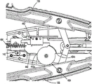
Now in conjunction with Fig. 1-5, be generally denoted as 100 according to the operation applicator of embodiment of the present disclosure.Operation applicator 100 generally includes Handleset 102, and Handleset 102 comprises housing 104, and housing 104 has upper half-shell 104a and housing lower half 104b.Handleset 102 further comprises and is fastened on the housing 104 pivotly and from its outward extending a pair of handle 106.Channel components 108 is fixedly secured on the housing 104 and from it and stretches out, and stops in jaw assembly 110.
See Fig. 1-4, the half housing 104a and the 104b of applicator 100 are fixed together by engaging with each other fixed engagement.Housing 104 limits and is formed among the housing lower half 104b to support and to show the window 104c of counting mechanism, as describing in more detail below.Housing 104 is formed by appropriate plastic material.
See Fig. 4, handle 106 is fastened on the housing 104 by handle pivot post (handle pivot post) 104d, and handle pivot post 104d extends and enters into each hole 106a that forms at handle 106 from housing lower half 104b.Handleset 102 comprises link component 122, and the pivotal point 106b place of link component 122 in being formed on each handle 106 is pivotably connected on each handle 106.The far-end 122a of each link component 122 is pivotably connected to via drive pin 124 and is formed on the pivotal point 140a that drives in the passage 140.Each end of drive pin 124 is slidably received among the elongated passageway 104e, and elongated passageway 104e is formed among each upper half-shell 104a and the housing lower half 104b.In use, as describing in further detail below, along with handle 106 is extruded, link component 122 distad promotes to drive passage 140 via drive pin 124.
See Fig. 4 and Fig. 6-12, applicator 100 comprises and is slidably disposed on the tubular lid clip push rod 160 below 130.Push rod 160 comprises the far-end 160a that limits pusher 160c, and pusher 160c is configured and be suitable for optionally engaging/moves the farthest side clip " C1 " that is stored in the operation applicator 100.Push rod 160 further comprises near-end 160b, and near-end 160b limits wherein proximal window 160d to hold drive pin 124 slidably in wherein.Push rod 160 further qualification distal window 160e wherein are operatively to engage with regulator 162, as what will describe in more detail below.Push rod 160 also comprises fin (fin) 160f that protrudes and be positioned at the nearside of close relatively proximal window 160d from its lateral edges.
See Fig. 4 and Fig. 4 A-4C, applicator 100 further comprises the motion amplification system, and the motion amplification system has the bellcrank gear 154 that is supported on pivotly in the housing 104 and is supported on accelerator housing 156 in the housing 104 slidably.Bellcrank gear 154 comprise be configured to pivot be connected to trunnion 154a on the housing 104, be supported on discoid body 154b on the trunnion 154a, from the radially extended arm 154c of discoid body 154b be supported on trunnion 154a and go up or integrally form with it and the localized spur gear 154d of contiguous discoid body 154b.Bellcrank gear 154 limits brake or the groove 154e (seeing Figure 24) in the lateral edges that is formed on discoid body 154b and is formed on the slit 154f of the portrait orientation among the arm 154c.It can be as the sector gear shown in Fig. 4 C the best also that the spur gear 154d of bellcrank gear 154 limits a plurality of gear teeth 154g that are formed in its lateral edges.
Continuation is with reference to figure 4 and Fig. 4 A-4C, the acceleration tooth bar 156 of motion amplification system comprises basal wall (base wall) 156a, basal wall 156a limits and forms slit 156b wherein, elongated, longitudinal extension, is used for holding slidably the trunnion 154a of bellcrank gear 154.Quickening tooth bar 156 comprises in the opposite direction the sidewall 156c that protrudes from the lateral edges of basal wall 156a and is formed on the sidewall 156c and with the slit 156b of basal wall 156a and align or aligned tooth bar 156d.Tooth bar 156d is constructed to engage with the gear teeth 154g of the spur gear 154d of bellcrank gear 154.
See Fig. 6, the slit 154f of the arm 154c of bellcrank gear 154 be configured and be sized to slidably and the protruding joint 162d that holds regulator 162 rotationally in wherein.In use, along with driving distad translation of passage 140, make to drive passage 140 and quicken tooth bar 156 interconnected biasing members 158 distal motion acceleration one after the other tooth bar 156.Along with quickening tooth bar 156 distal motion, because the protruding joint 162d of regulator 162 advances in the slit 154f of the arm 154c of bellcrank gear 154, quicken tooth bar 156 and cause that bellcrank gear 154 rotates and promotion regulator 162, and distad promote push rod 160 successively.
See Fig. 4, Fig. 9 and Figure 14, formation operation clip " C " is to slide with it and/or to be loaded and/or to remain among the passage 170d of clip carrier 170 along the mode of its slip.Passage 170d is configured and is sized in the mode of point to tail one formation or a plurality of operation clip " C " are remained on wherein slidably.
See Figure 12 and Figure 14, the far-end of clip carrier 170 comprises a pair of isolated resilient tangs (tang) 171.Tang 171 be configured and be suitable for optionally engaging operation clip " C " formation that remains in the carrier 170 farthest side operation clip " C1 " after stride portion (backspan).
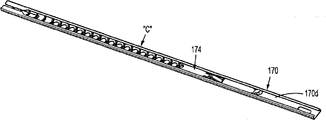
See Fig. 4, Fig. 4 F, Fig. 7 and Figure 15, applicator 100 further comprises the clip follower 174 among the passage 170d that is slidably disposed on clip carrier 170.As below describing in more detail, clip follower 174 is positioned at after the formation of operation clip " C " and is set to promote forward clip " C " formation between the period of energization of applicator 100.As below will describing in more detail, clip follower 174 by clapboard 180 forward and reciprocating motion backward activate.
See Fig. 4 F and Fig. 7, clip follower 174 comprise define planar main part 174a, from distally that main part 174a makes progress substantially and extends back projection 175 and nearside projection 176 downwards basic from main part 174a and that extend back.Distally projection 175 is included in the distal part 175a of downward extension under the plane that is limited by main part 174a and upwardly extending portions of proximal 175b on the plane that is limited by main part 174a.
The portions of proximal 175b of distally projection 175 is configured and is sized to the window 172 that optionally engages among the upper wall 170a that is formed on clip carrier 170.In use, the portions of proximal 175b of the distally projection 175 of clip follower 174 joint in the window 172 in being formed on the upper wall 170a of clip carrier 170 has prevented that the clip follower from advancing or moving on proximal direction.
See Fig. 4, Fig. 7-9, Figure 16 and Figure 17, applicator 100 further comprises the clapboard 180 that is slidably disposed in Handleset 102 and the channel components 108.Clapboard 180 is located or is arranged under the clip carrier 170.Clapboard 180 comprises optionally operatively to be inserted in the far-end 180a of the taper basically between the jaw 120.Clapboard 180 defines along its length and longitudinally extends and be formed on a plurality of isolated window or the hole 180b of its raised section, the distal window or the hole 180c in distally that are positioned at hole 180b and the nearside transversal orientation slit 180d that is positioned at the nearside of hole 180c.
See Fig. 4, Fig. 8, Figure 16 and Figure 17, applicator 100 comprises the distally dead lock 178 that is supported by tubular lid 130.Distally dead lock 178 comprises tail or protruding 178a, and tail or protruding 178a extend backward and downwards basically and be configured and be sized in the distal window or hole 180c that is contained in the clapboard 180.
See Fig. 4, Fig. 4 D, Fig. 4 E, Fig. 6, Figure 11, Figure 13, Figure 18 and Figure 20, applicator 100 comprises the clapboard reversing of motion mechanism with the form of pivotal arm 179, and its housing lower half 104b that is supported on housing 104 pivotly goes up the reverse translation that is transferred to clapboard 180 with the translation that will drive passage 140.On the end that pivotal arm 179 comprises the pivot boss 179a that is configured to be pivotably connected on the housing 104, be arranged on pivotal arm 179 and at upwardly extending first bar in the side opposite or finger 179b, and be arranged on second end of pivotal arm 179 and at upwardly extending second bar in the side opposite or finger 179c with pivot boss 179a with pivot boss 179a.First bar or finger 179b are configured and are suitable for engaging the nearside slit 180d of clapboard 180.Second bar or finger 179c are constructed to engage and are formed on the slit 140g that drives in the passage 140, and are connected among the window 140g that is defined in the driving passage 140.Slit 140g comprises its axially and laterally the longitudinal extension distal part and longitudinal extension portions of proximal of skew each other, and the lateral part of interconnection distally and portions of proximal.
In use, as below describing in more detail, along with driving passage 140 distal motion, second bar or finger 179c after the down-time period (promptly, drive the length of distal part of longitudinal extension of the slit 140g of passage 140) on distal direction, move, thus rotate pivotal arm 179 and at second party move upward first bar or finger 179b.Along with first bar or finger 179b move upward in second party, first bar or finger 179b pull out clapboard 180 between jaw 120, the fin 160f that advances simultaneously again proximad to advance or promote pusher 160 is with motion pusher 160 on proximal direction, so that its push rod 160c shifts out between jaw 120, vice versa.Along with clapboard 180 moves, see Figure 17, thereby the far-end 180a of clapboard 180 keeps jaw 120 to be spaced apart from each other facing to the protruding commentaries on classics of the inner surface of jaw 120 on distal direction.
See Fig. 4, Fig. 6-11, Figure 13, Figure 18 and Figure 19, applicator 100 comprises in the housing 104 that can be supported on Handleset 102 and the channel components 108 and the driving passage 140 that extends betwixt with moving back and forth.The near-end that drives passage 140 is supported between the upper half-shell 104a of housing 104 and the housing lower half 104b and the far-end that drives passage 140 is supported between the tubular lid 130 and outer tunnel 132 of channel components 108 at clapboard 180 lower position places.
The far-end that drives passage 140 is basic U-shaped passage, comprises a pair of isolated sidewall 140b, and described sidewall 140b is leaving outer tunnel 132 and extending from striding the 140c of portion thereafter on the direction of tubular lid 130.Drive passage 140 and further limit the drive pin recess 140a that strides after being formed among the 140c of portion to hold the drive pin 124 by wherein pivotally.Drive distal position place that passage 140 further is limited to drive pin recess 140a from after stride the rib 140e that the 140c of portion protrudes.Drive and to stride the reciprocal qualification groove 140f that forms among the 140c of portion after distal position that passage 140 further is limited to slit 140e is in.
See Fig. 4, Fig. 8, Fig. 9, Figure 12, Figure 14-16 and Figure 19, applicator 100 comprises the driving passage strap (drive channel strap) 143 that is fastened in the driving passage 140.Strap 143 is fastened to the erection part 140b that drives passage 140 and goes up so that across its extension.Strap 143 is fastened at the distal position place that back and forth limits groove 140f and drives on the passage 140.Strap 143 is fastened to and drives on the passage 140 so that clapboard 180 is extending under the strap 143 and on the jaw 120.
See Fig. 4, Fig. 4 G, Fig. 6, Figure 10 and Figure 21, applicator 100 further comprises via drive pin 124 and is connected to the audition/tactile indicators 148 that drives on the passage 140.Indicator 148 comprises elasticity finger 148a and pair of projections 148b.In use, as below describing in further detail, move back and forth along with applicator 100 activated and drive passage 140, the first elasticity finger 148a of indicator 148 interacts to produce audition and/or tactile feedback to the user with the corresponding complementary structure or the lug (ledge) 149 that are arranged in the applicator 100.The boss 148b of indicator 148 advances in being formed at the path 10 4e of upper half-shell 104a and provides support to prevent indicator 148 rotations to indicator 148.
See Fig. 4, Fig. 6, Figure 10, Figure 11, Figure 13, Figure 18 and Figure 20, applicator 100 further comprises the biasing member 146 with the tension spring form, it operationally is fastened on the near-end that drives passage 140 and the housing 104 and between the near-end and housing 104 that drive passage 140, will drive passage 140 often and remain on withdrawal or nearest side position.Biasing member 146 plays being positioned at that clip " C " between the jaw 120 is withdrawn after forming or the effect of the driving passage 140 that helps to withdraw.
See Fig. 4, Fig. 4 H, Figure 11, Figure 13, Figure 18 and Figure 20, the near-end that drives passage 140 comprises rack member 141, and it is fastened on the drive pin 124 and can moves with driving passage 140.Rack member 141 be configured and be suitable for be supported on housing 104 in ratchet pawl 142 engage.Rack member 141 and ratchet pawl 142 limit ratchet mechanism 144.In use, axially moved along with driving passage 140, rack member 141 also moves.Rack member 141 limits one group of rack tooth 141a with such length: arrive nearside or farthest side position along with driving passage 140, when rack member 141 changed between proximal movement and distal movement, it allowed ratchet pawl 142 oppositely and return on rack member 141.
See Fig. 1-4, Fig. 8, Figure 10, Figure 12, Figure 14-17 and Figure 19, applicator 100 comprises on the far-end that is installed in channel components 108 or at the far-end of channel components 108 and a pair of jaw 120 that can be activated by the handle 106 of Handleset 102.Jaw 120 is by forming such as the biological conforming materials that is fit to, for example, and rustless steel or titanium.
See Fig. 1-4, Fig. 6, Figure 11, Figure 13 and Figure 20, applicator 100 further comprises the counting mechanism 190 in the housing 104 that is supported on Handleset 102.Counting mechanism 190 comprises display 192, processor 194 and with the energy 198 of forms such as battery.Display 192 is a liquid crystal display, and it shows one or more operating parameters of applicator 100 to the surgeon.The operating parameter that shows can be number, location parameter, the operating time of use or other arbitrary parameters of operation of the amount of residue clip or number, already used clip.
See Figure 1A and Fig. 1 C, applicator 100 comprises being supported on the housing 104 and being inserted in and transports wedge 200 between the handle 106.Transport wedge 200 and play transporting and/or the 106 spaced apart or not effects of extruding of memory period maintenance handle at applicator 100.Transport on the lug 192a that wedge 200 is connected to counting mechanism 190, thereby for the terminal use uses applicator 100, thereby the terminal use must shift out and transports wedge 200 and also shift out lug 192a and activate counting mechanism 190.
See Figure 1A and Fig. 1 C, transport wedge 200 and comprise main part 202 with the form of chimb that it limits passage 204, the part that passage 204 was configured and was sized to housing case 104 is in wherein.Transporting wedge 200 comprises and stretches out from the both sides of main part 202 and be constructed to hold handle 106 in erection part 206 wherein.Transport wedge 200 and further comprise the projection 208 that extends internally from the opposition side of erection part 206.The projection 208 of transporting wedge 200 is configured and is sized to when transporting wedge 200 and suitably be fastened on the applicator 100 and engages with handle 106.
In conjunction with Figure 22-53, provide CovidienSURGICLIP
TMThe operation of applicator 100.Before the initial arbitrarily extruding of the handle 106 of applicator 100, see Figure 22-24, drive pin 124 is positioned at nearest side position, ratchet pawl 142 is positioned at the distally of the tooth bar 140d that drives passage 140, the second finger 179c of pivotal arm 179 is located at farthest side position in the window 140g distal part that drives passage 140 so that clapboard 180 is positioned at the farthest side position, and does not have clip " C " to be positioned in the jaw 120.Because drive pin 124 is at nearest side position, push rod 160, regulator 162 and driving passage 140 are also at nearest side position.
Be positioned under the situation of nearest side position at driving passage 140 and push rod 160, quicken tooth bar 156 and be positioned at nearest side position place, and the second elasticity finger 148b of indicator 148 be arranged on the nearside at edge 149.Equally, before the handle 106 initial extruding of applicator 100, be positioned at clapboard 180 under the situation of farthest side position, its far-end 180a is inserted between the jaw 120.
Before initial extruding, there is not clip " C " to appear in the jaw 120 equally.During the initial extruding of handle 106, clip " C " at first is loaded onto in the jaw 120.See Figure 25-33, during the initial extruding of handle 106, make the far-end 122a of link component 122 with respect to housing 104 distal motion.Along with the far-end 122a distal motion of link component 122, drive passage 140 thereby make drive pin 124 distal motion that the distally axially-movable is transferred to.
Along with driving passage 140 distal motion, biasing member 158 is distal motion with it.Along with biasing member 158 distal motion, biasing member 158 draws on distal direction and quickens tooth bar 156.Be pulled on distal direction along with quickening tooth bar 156, quicken tooth bar 156 and make bellcrank gear 154 rotate and the distally axially-movable is transferred to the protruding joint 162d of regulator 162 around trunnion 154a, the protruding joint 162d of regulator 162 is transferred to push rod 160 with the distally axially-movable successively.Along with driving passage 140 distal motion, biasing member 146 is stretched or extends.
See Figure 25, Figure 32 and Figure 33, during the initial extruding of handle 106, indicator 148 is together with the distal movement distal motion that drives passage 140.In use, indicator 148 plays the effect that produces audition sound and/or tactile vibrations, thereby the handle 106 of indication user operation applicator 100 has passed through to the small part stroke.Especially, see Figure 32 and Figure 33, along with handle 106 activated, the first elastic arm 148a of audition/tactile indicators 148 advances above lug 149 and/or along lug 149, and described lug 149 is formed among upper half-shell 104a and the housing lower half 104b at least one and is therefore crooked.Arrive the near-end of lug 149 along with the arm 148a of audition/tactile indicators 148, elastic arm 148a is fastened on the near-end of lug 149 and with the surperficial 149a of lug 149 and contacts, along with elastic arm 148a contacts with the surperficial 149a of lug 149, thereby produce first audible sound and tactile vibrations.First indication indication user's clip " C " of audition/tactile indicators 148 is suitably loaded.
As Figure 28 and shown in Figure 30, same during the initial extruding of handle 106, along with push rod 160 moves on distal direction, its pusher 160c engage farthest side clip " C1 " after stride portion and begin farthest side clip " C1 " distal motion or promote out clip carrier 170 and enter jaw 120.Along with farthest side clip " C1 " distal motion, the tang 171 of clip carrier 170 be deflected or by cam driven ground break away from farthest side clip " C1 " engage and return its not deflection or not by the state of cam driven with subsequently clip in the formation of extracting clip " C ".During the initial extruding of handle 106, push rod 160 has been pushed into to be enough to farthest side clip " C1 " is placed on amount among the passage 120a of jaw 120.
As Figure 27 and shown in Figure 31, same during the initial extruding of handle 106, move on distal direction along with driving passage 140, the rack member 141 of ratchet mechanism 144 is caused that by distal motion the tooth 141a of rack member 141 moves to the tooth of crossing or stride across ratchet pawl 142 with the indented joint and the motion of ratchet pawl 142.When the rack member 141 of ratchet mechanism 144 moves to when engaging with ratchet pawl 142, drive passage 140 and can not return home position or side position recently, left ratchet pawl 142 up to rack member 141.
During the initial extruding of handle 106, shown in Figure 25-33, drive passage 140 and engaged (that is, resting) up to the finger of pivotal arm 179 179c by the lateral part of the slit 140g that drives passage 140 by distal motion.When the finger 179c of the lateral part of slit 140g and pivotal arm 179 in abutting connection with the time (, rest finish after), the further distal movement that drives passage 140 causes finger 179c motion and rotates pivotal arm 179.The rotation of pivotal arm 179 causes the motion of its finger 179b, this causes that successively clapboard 180 is pulled on proximal direction, thereby from recalling its far-end 180a between the jaw 120 and allowing jaw 120 final closed or approaching, and the fin 160f that promotes push rod 160 to be promoting push rod 160 on proximal direction, thereby makes its far-end pusher member 160c also allow jaw 120 final closed or approaching from motion between the jaw 120.
When reaching the required rotation of pivotal arm 179, pivotal arm 179 is along with the advance portions of proximal of the slit 140g by driving passage 140 of the finger 179c of pivotal arm 179 stops operating.The finger 179c of pivotal arm 179 remains in the portions of proximal of the slit 140g that drives passage 140 up to finishing the stroke that drives passage 140.
As shown in figure 38, along with clapboard 180 moves on proximal direction, thereby clapboard 180 with respect to clip follower 174 proximal motion with its window 180b with respect to the nearside of clip follower 174 projection 176 proximal motion.
As Figure 28 and shown in Figure 30, during the initial extruding of handle 106, as mentioned above, push rod 160 is with driving passage 140 distal motion, up to quickening tooth bar 156 near the rib among the lower house 104b of housing 104, the distally of at this moment quickening tooth bar 156 advances and is stopped.Stoped the further distally of quickening tooth bar 156 to advance, shown in figure 32, further distad advanced along with driving passage 140, the elasticity finger 148a that drives passage 140 pullings or crooked indicator 148 crosses the near-end of lug 149.Like this, produce first indication of suitably having been loaded (that is, audition and/or tactile) to user indication operation clip " C ".Equally, owing to stoped acceleration tooth bar 156 further distally to advance, so thereby having stoped bellcrank 154 to rotate has stoped push rod 160 further distally to advance.
With reference now to Figure 34-40,, during the further extruding of handle 106, the far-end 122a that causes link component 122 is with respect to housing 104 further distal motion.Along with the further distal motion of far-end 122a of link component 122, thereby cause that drive pin 124 further distal motion give to drive passage 140 with distal shaft to Motion Transmission.
Shown in Figure 34-40,, advance by the further distally of preventing throw-out lever 160 near the acceleration tooth bar 156 of the rib among the lower house 104b that is formed on housing 104 along with driving passage 140 by further distal motion.Be stopped owing to quicken the distally propelling of tooth bar 156, the further rotation of bellcrank gear 154 is stopped, and this makes the distally propelling of regulator 160 stop successively, and the distally propelling of push rod 160 is stopped.
In addition, as shown in figure 44, because the far-end 180a of clapboard 180 shifts out between jaw 120, along with driving passage 140 by further distal motion, the distal side edge that drives passage 140 and/or drive passage strap 143 engages the cam face 120b of jaw 120, thereby causes that jaw 120 is towards close to each other and form (form) and be inserted in therebetween operation clip " C1 ".Because driving passage strap 143 is fixed on the driving passage 140 and therewith motion, so drive passage strap 143 be used for covering drive passage 140 make jaw 120 near during jaw 120 remained on drive passage 140, and in the operating process of applicator 100, clapboard 180 remained on and drives in the passage 140.
As shown in figure 45, operation clip " C1 " can form or be crimped onto in vascular " V " or other any biological tissues.
Because the boss 148b translation of indicator 148 is by the slit 160d of push rod 160, so allow to drive passage 140 with respect to push rod 160 distal motion.
In addition, fully distad advanced along with driving passage 140, as shown in figure 37, thus the rack member 141 of ratchet mechanism 144 is made the tooth 141a of rack member 141 be made rack member 141 and ratchet pawl 142 break away from each other by the distal movement to the tooth of ratchet pawl 142 by distal motion to the position that exceeds ratchet pawl 142.Like this, allow to drive passage 140 and freely return home position or nearest side position.
Shown in Figure 32 and 33, along with driving passage 140 by distal motion, the elastic arm 148a of audition/tactile indicators 148 engaging (snap over) on the far-end of lug 149 and the surperficial 149a of contact lug 149, thereby produce the audition sound and/or tactile vibrations.This audition sound and/or tactile vibrations are consistent with the loading of operation clip " C ".
As shown in figure 43, along with driving passage 140 by further distal motion, thereby the elastic arm 148a of audition/tactile indicators 148 is fastened on the far-end of lug 149 and produces the further audition sound and/or tactile vibrations.This audition sound and/or tactile vibrations are consistent with being completed into of operation clip " C ".
Continue with reference to figure 35-40, during the further extruding of handle 106, because lug 192a shifts out from counting mechanism 190, distad advanced along with driving passage 140, the contact 194a of its protruding joint 140e joining process device 194, thus finish circuit and make processor 194 work as mentioned above.
With reference now to Figure 41-45,, shown the applicator 100 after the whole stroke of handle 106 or extruding and during handle 106 is opened.In this case, drive passage 140 at the distal position place, push rod 160 is at the distal position place, clapboard 180 is at the proximal position place, accelerator 156 is spaced apart with driving passage 140, and each biasing member 146 and 158 is stretched, and ratchet pawl 142 is positioned at the nearside of tooth bar 140d.
Shown in Figure 46-52,, make the far-end 122a of link component 122 with respect to housing 104 proximal motion opening or deenergized period of handle 106.Along with the far-end 122a proximal motion of link component 122, drive passage 140 thereby make drive pin 124 proximal motion that proximal shaft is arrived to Motion Transmission, and pass to push rod 160 successively.The contraction of biasing member 146 has promoted to drive the proximal movement of passage 140.Alternative, the release of handle 106 cause biasing member 146 to recall driving passage 140 on proximal direction.
Along with driving passage 140 by proximal motion, drive the distal side edge of passage 140 and/or drive of the cam face 120b disengaging of passage strap 143 from jaw 120, thereby jaw 120 is separated from each other so that the far-end 180a of clapboard 180 is inserted between the jaw 120 again, and another operation clip " C " is contained between the jaw 120.Especially, along with driving passage 140 proximal motion, the lateral part of slit 140g acts on finger 179c and goes up to cause that pivotal arm 179 rotates and to cause that the finger 179b of pivotal arm 179 distad promotes clapboard 180.Along with clapboard 180 moves on distal direction, shown in Figure 51 and Figure 52, the far-end 180a of clapboard 180 is inserted again or is reintroduced in the jaw 120, thereby jaw 120 is opened.
As Figure 49 and shown in Figure 50, along with clapboard 180 distal motion, thereby the nearside projection 176 of clip follower 174 is bonded among the window 180b of clapboard 180 and distad is pushed given distance.Along with clip follower 174 distad is pushed, clip " C " formation also distad is pushed.As shown in figure 50, when clapboard 180 reaches the farthest side position, clip track (clipchannel) 170 in abutting connection with, engage, promote or the portions of proximal 175b that otherwise takes distally projection 175 to by cam is located substantially on the below of the distal part 175a of distally projection 175 up to net (web) 180f of clapboard 180.In the process of so doing, in the portions of proximal 175b of distally projection 175 motion the window 172 with the more distally of the recruitment that extends to clip track 170.
Shown in Figure 51 and Figure 52, along with clip follower 174 is pushed forward, clip " C " formation travels forward, farthest side clip " C1 " comes the far-end of motion pusher 160c with gear driven below the pusher 160c of push rod 160, grasped by the tang 171 of applicator 170 up to farthest side clip " C1 ".
Temporarily return Figure 48, move on proximal direction along with driving passage 140, the arm 148a engaging of audition/tactile indicators 148 is got back on the lug 149 and is reset audition/tactile indicators 148 to be used for the next one emission stroke or the extruding of handle 106.
Further on proximal direction, move along with driving passage 140, drive passage 140 and engage acceleration tooth bar 156, cause that quickening tooth bar 156 moves on proximal direction.Thereby quickening tooth bar 156 causes bellcrank gear 154 to rotate at proximal direction motion push rod 160 around trunnion 152a in the motion of proximal direction.In addition, move on proximal direction along with driving passage 140, its protruding joint 140e breaks away from the contact 194a of processor 194.
Get back to Figure 53 now, shown at the whole stroke of handle 106 or clip far-end of the applicator 100 after discharge wherein fully after the extruding and in the end.After clip emission in the end, as shown in Figure 53, the nearside projection 176 of clip follower is arranged in the side opening farthest or window among the hole 180b of clapboard 180.Like this, along with clapboard 180 distal motion after the clip emission, clip follower 174 is also with aforesaid mode distal motion.Therefore, along with clip follower 174 distal motion, its distally projection 175 moves to the far-end of the farthest side window in the window 172 of clip carrier 170.Like this, the inner surface of the roof of the portions of proximal 175b engaging clip carrier 170 of distally projection 175 and downwards by cam driven or promotion.
Along with the portions of proximal 175b of distally projection 175 downwards by cam driven or promotion, the protruding 178a of the upper surface of the protruding 178a of the distal part 175a engage latch device 178 of distally projection 175 and downward cam driven or promotion dead lock 178, stride across and be supported on the path that drives the strap 143 on the passage 140, and enter among the distal window 180c of clapboard 180.Like this, distad be pushed into if drive passage 140, strap 143 will be in aforesaid mode near the protruding 178a of dead lock 178 and prevention or hinder strap 143 distal motion, and successively, stops or hinder to drive passage 140 distal motion.At present, ratchet pawl 142 is positioned at and rests the place, i.e. the far-end of tooth bar 140d, and handle 106 is arranged in the position of opening fully and therefore can not opens to a greater degree.In this structure, applicator can not be re-used by locking.
The size that depends on the clip of performing the operation, the size of the parts of applicator 100 is certainty ratio (scaled) correspondingly.The parts of most of different size applicators will be mutually the same basically.The part dimension relevant with the width of clip, such as jaw 120 and clapboard 180, perhaps relevant with clip length part dimension correspondingly is conditioned such as push rod 160, bellcrank gear 154 and pivotal arm 179.Like this, each applicator with different size will be assembled in essentially identical mode, and its internal mechanism will be operated in essentially identical mode.
For example, applicator 100 can be with relatively little, medium and big ratio setting, wherein storage of the applicator of every kind of size and relative little, the medium or big operation clip of emission.Based on the relative size of operation clip, corresponding applicator and their corresponding components be certainty ratio suitably.Yet according to the disclosure, each in the various sizes applicator comprises identical parts and can assemble with mutually the same order.Like this, the technical staff of assembling applicator will only need to learn to assemble a kind of size applicator required order and/or step, and can assemble the applicator of other sizes successively with being equal to, and need not learn new assembling sequence or step.
Therefore, it is substantially the same each other to be used for the assemble method and/or the step of relatively little, medium or big applicator.
At least following parts or part change shape based on the relative size or the ratio of applicator, that is, and and the length of the slit of the length of the arm of pivotal arm 179, the translation therein of acceleration tooth bar 156; And the degrees of rotation of bellcrank gear 154.
Many other remaining parts or part are identical or have less variation in characteristic size or ratios.Yet if desired, the shape that can revise following part to be to reach identical result, that is, and and the length of the slit 154f of bellcrank gear 154, and/or be formed on the length of the slit 156b among the basal wall 156a that quickens tooth bar 156.
Consider applicator for relative small scale, given bellcrank gear 154 relative to small scale about 45 ° rotates the about 0.345 inch axial displacement of push rod 160 that will cause relative small scale, so that undersized relatively clip is loaded in the jaw 120.Similarly, consider applicator for relative moderate proportions, given bellcrank gear 154 relative to moderate proportions about 70 ° rotates push rod 160 about 0.485 inch axial displacement that will cause relative moderate proportions, so that middle-sized relatively clip is loaded in the jaw 120.Similarly, consider applicator for relative vast scale, given bellcrank gear 154 relative to vast scale about 90 ° rotates push rod 160 about 0.710 inch axial displacement that will cause relative vast scale, so that large-sized relatively clip is loaded in the jaw 120.
In optional embodiment, shown in Figure 54-57, consider that the near-end that drives passage 140 can comprise or limit and its formation one integral body and be constructed to and be suitable for the tooth bar 140d of engages ratchet pawl 142.Therefore using and operating identically with ratchet mechanism 144 basically of ratchet mechanism 244 will no longer go through here.
In another embodiment, as top shown in Figure 4, applicator 100 can be provided with and be configured to the energy 198 is fixed to strap 196 on the housing 104.
In one embodiment, consider equally along with driving passage 140 distal motion, and along with the elastic arm 148a of audition/tactile indicators 148 is fastened on the distal side edge of lug 149, thereby elastic arm 148a can clash into or contact the surface that is formed in the housing 104 and will further or once more amplify the vision sound and/or tactile vibrations.
Forward Figure 58-69 now to, according to optional embodiment of the present disclosure, operation applicator is commonly designated as 300.Operation applicator 300 is identical with operation applicator 100 basically, therefore only goes through here in order to discern the different necessary degree of its structure and operation.
As Figure 58,60 and 64-66 shown in, applicator 300 comprises the motion amplification system with bellcrank gear 154, and is supported on the acceleration tooth bar 356 in the housing 104 slidably.Quicken tooth bar 356 and comprise basal wall 356a, basal wall 356a limit be formed on elongated, longitudinal extension wherein slit 356b to be used for holding slidably the trunnion 154a of bellcrank gear 154.Quicken tooth bar 356 and comprise, and be formed among the sidewall 356c and and overlap or aligned tooth bar 356d with the slit 356b of basal wall 356a from the outstanding in the opposite direction sidewall 356c of the lateral edges of basal wall 356a.Tooth bar 356d is constructed to engage with the gear teeth 154g of the spur gear 154d of bellcrank gear 154.Quicken tooth bar 356 and further comprise from the outstanding cam member 356e of the distal side edge of basal wall 356a, and from the outstanding protruding joint 356f of the distal side edge of sidewall 356c.
The length of the slit 356b of the basal wall 356a of acceleration tooth bar 356 will depend on that the size of applicator 300 changes.For less relatively applicator (for example, apply relative applicator) than Small clamp, the length of quickening the slit 356b of tooth bar 356 will be shorter relatively, and for relatively large applicator (for example, apply the applicator of big clip), the length of quickening the slit 356b of tooth bar 356 will be longer relatively.
In the use, as what below will describe in detail, axially moved or translation along with quickening tooth bar 356, the tooth bar 356d that quickens tooth bar 356 engages with the gear teeth 154g of the spur gear 154d of bellcrank gear 154 to cause that bellcrank gear 154 rotates or pivot around trunnion 154a.
As Figure 58,61 and 67-69 shown in, applicator 300 comprises reversing of motion mechanism, and reversing of motion mechanism has the translation that is used for the translation of clapboard 180 is passed to driving passage 140 of the clapboard pivotal arm 379 among the housing lower half 104b that is supported on housing 104 pivotally.Pivotal arm 379 comprises the pivot boss 379a that is configured to be pivotably connected on the housing 104, an end that is arranged on pivotal arm 379 and at upwardly extending first bar in the side opposite with pivot boss 379a or finger 379b, and is arranged on the other end of pivotal arm 379 and second bar or the finger 379c that extends in the direction identical with pivot boss 379a.First bar or finger 379b are constructed to and are suitable for being bonded among the nearside slit 180d of clapboard 180.Second bar or finger 379c are constructed to be bonded among the slit 358b that is formed in the arm connecting rod 358 (Figure 62), and described arm connecting rod 358 is connected to and is limited among the window 140h that drives in the passage 140.
In the use, as what below will go through, with driving passage 140 distal motion, after the down-time period, thereby arm connecting rod 358 promote second bar of pivotal arms 379 or finger 379c with first or distal direction on motion make first bar or finger 379b second or proximal direction on motion and cause that clapboard 180 moves upward in second party, vice versa.Along with clapboard 180 moves on distal direction, as what below will discuss, thereby the inner surface of clapboard 180 cam driven jaws 120 keeps jaw 120 to be separated from each other.
As Figure 58,59 and 64-66 shown in, applicator 300 further comprises and is supported on the audition/tactile indicators 348 that drives on the passage 140.Indicator 348 comprises the first elasticity finger 348a and the second elasticity finger 348b.In the use, as below will be in greater detail, along with activateding and drive passage 140, applicator 300 moves back and forth, the first elasticity finger 348a of indicator 348 interacts producing audition and/or tactile feedback to the user with being arranged on respective complementary structure in the applicator 300, and the interact applicator 300 of thinking different size of the second elasticity finger 348b of indicator 348 and the cam member 356e that quickens tooth bar 356 is regulated the stroke of applicators 300.
As Figure 58,62 and 67-69 shown in, applicator 300 further comprises arm connecting rod 358, arm connecting rod 358 is arranged in the housing 104 slidably and is operably connected to and drives in the passage 140 with driving passage 140 translations.Arm connecting rod 358 comprise the slit 358b that defines wherein main part 358a, from the upper surface of main part 358a outstanding lead wall 358c and from the proximal of main part 358a at upwardly extending bar 358d upward.The slit 358b of arm connecting rod 358 is constructed to hold slidably second bar or the finger 379c of pivotal arm 379.The wall 358c that leads of arm connecting rod 358 is sized on the surface that drives passage 140 and advances.The bar 358d of arm connecting rod 358 is sized to be slidably received within and is formed among the window 140h that drives in the passage 140.The window 140h that drives passage 140 be sized to be limited to drive passage 140 distal motion the time and arm connecting rod 358 activate time therebetween section idle hours of pivotal arms 379.
With reference to figure 64-69, it is different that the operation of description operation applicator 300 is compared with operation applicator 100.Before any initial extruding of the handle 106 of applicator 300, shown in Figure 64 and Figure 67, drive pin 124 is positioned at nearest side position, ratchet pawl 142 is positioned at the distally of the tooth bar 140d that drives passage 140, arm connecting rod 358 is positioned at the farthest side position with respect to the window 140h of the nearest side position of housing 104 and driving passage 140, and does not have clip " C " to be arranged in jaw 106.Because drive pin 124 is at nearest side position, push rod 160, regulator 162 and driving passage 140 are also at nearest side position.Because push rod 160 is positioned at nearest side position, quicken tooth bar 356 and be positioned at nearest side position, and the second elasticity finger 348b of indicator 348 is arranged in the nearside of the cam member 356e that quickens tooth bar 356.Equally, before the initial extruding of the handle 106 of applicator 300, clapboard 180 makes that in the farthest side position far-end 180a of clapboard 180 is inserted between the jaw 120.
Along with driving passage 140 distal motion, shown in Figure 65 and Figure 68, indicator 348 is distal motion therewith.Along with indicator 348 distal motion, its second elasticity finger 348b draws on distal direction and quickens tooth bar 356.Be pulled on distal direction along with quickening tooth bar 356, quicken that tooth bar 356 causes that bellcrank gear 154 rotates around trunnion 154a and with distal shaft to Motion Transmission to the regulator 162 protruding joint 162c, this successively with distal shaft to Motion Transmission to push rod 160.Along with driving passage 140 by distal motion, biasing member 146 is stretched or extends.
During the initial extruding of handle 106, shown in Figure 67 and Figure 68, drive passage 140 and engaged (that is, resting) up to the bar 358d of arm connecting rod 358 by the end wall of the window 140h that drives passage 140 by distal motion.When the bar 358d of the end wall of window 140h and arm connecting rod 358 in abutting connection with the time (, leaving back, the place of resting), as shown in Figure 69, the further distal movement that drives passage 140 causes the distal movement of arm connecting rod 358.Along with arm connecting rod 358 distal motion, the lateral part of the slit 358b of arm connecting rod 358 will cause that pivotal arm 379 rotates, this causes that successively clapboard 380 moves on proximal direction, thereby from recalling its far-end 180a between the jaw 120 and allowing jaw 120 final closed or approaching.When reaching the required rotation of pivotal arm 379, pivotal arm 379 is along with the advance longitudinal component of the L shaped slit 358b by arm connecting rod 358 of the finger 379c of pivotal arm 379 stops operating.The finger 379c of pivotal arm 379 remains in the longitudinal component of L shaped slit 358b of arm connecting rod 358, up to finishing the stroke that drives passage 140.
Shown in Figure 64 and Figure 65, during the initial extruding of handle 106, as mentioned above, push rod 160 is with driving passage 140 distal motion, near the lug that is formed in the housing 104, the distally of at this moment quickening tooth bar 356 advances and is stopped up to the protruding joint 356f that quickens tooth bar 356.Owing to stoped the further distally of quickening tooth bar 356 to advance, shown in Figure 66, distad further advance along with driving passage 140, drive passage 140 from the cam member 356e back pulling of quickening tooth bar 356 or the second elasticity finger 348b of crooked indicator 348, move to the home position in proximal direction to allow push rod 160.Push rod 160 is by the back-moving spring 359 that has first end that is fixed on the push rod 160 and be fixed to second end on the housing its home position of withdrawing.
After the whole stroke of handle 106 or extruding and during the opening of handle 106, driving passage 140 moves on proximal direction.In operation, along with driving passage 140 proximal motion, the front bulkhead that drives the window 140h of passage 140 acts on the bar 358d of arm connecting rod 358 upward with pulling arm connecting rod 358 on proximal direction.Along with arm connecting rod 358 by proximal motion, arm connecting rod 358 makes pivotal arm 379 rotate, this causes that successively clapboard 180 moves on distal direction.Along with clapboard 180 moves on distal direction, the far-end 180a of clapboard 180 inserts again or introduces again in the jaw 120, thereby jaw 120 is opened.
Further move on proximal direction along with driving passage 140, the second elasticity finger 348b of indicator 348 engages the cam member 356e that quickens tooth bar 356, causes that quickening tooth bar 356 moves on proximal direction.Quicken the motion of tooth bar 356 on proximal direction and cause bellcrank gear 152 to rotate around trunnion 152a, thus on proximal direction motion push rod 160 and regulator 162.Along with driving passage 140 further motion on proximal direction, the second elasticity finger 348b of indicator 348 in the back of cam member 356e with cam driven, bending or engaging to engage with acceleration tooth bar 356 again.
Forward Figure 70-88 now to, be commonly designated as 400 according to the operation applicator of optional embodiment of the present disclosure.Operation applicator 400 is identical with operation applicator 100 basically, therefore will only go through here in order to discern the different necessary degree of its structure and operation.
As Figure 70,71 and 75-77 shown in, applicator 400 comprises the motion amplification system, the motion amplification system has the gear part 454 in the housing 404 that is supported on Handleset 402 rotationally.Gear part 454 comprises the main board 454a that limits turning cylinder, be supported on that main board 454a goes up and with the co-axial gear 454b of turning cylinder, and gear segment (gearsection) 454c that is formed on the outer edge of main board 454a.
As Figure 70,72 and 75-77 shown in, applicator 400 further comprises and supports or otherwise be connected the driving passage tooth bar 442 that drives on the passage 440.Drive passage tooth bar 442 and limit a plurality of gear teeth 442a that are formed in its lateral edges.Driving passage tooth bar 442 is configured and is sized to and makes its gear teeth 442a to engage with the gear 454b of gear part 454.In the use, along with driving passage 440 by translation, drive the 442 therewith translations of passage tooth bar, vice versa.
As Figure 70,73 and 75-77 shown in, the motion amplification system of applicator 400 also comprises the Push Rod Rack 462 that supports or otherwise be connected on the push rod 460.Push Rod Rack 462 limits a plurality of tooth 462a that are formed in its lateral edges, and the bar 462b that extends from its proximad.Push Rod Rack 462 is configured and is sized to and makes its gear teeth 462a to engage with the pitch 454c of gear part 454.In the use, along with push rod 460 by translation, therewith translation of Push Rod Rack 462, vice versa.
Shown in Figure 70,74 and 75, applicator 400 comprises push rod 460, and described push rod 460 has from the outstanding elasticity finger 460c in its surface.When Handleset 404 was in not squeezed state, shown in Figure 75, the elasticity finger 460c of push rod 460 was arranged in from driving the distally (Figure 75-77) of drive block (drive block) 440a that passage 440 extends.Equally, at first not in the squeezed state, there is not clip " C " to be arranged in jaw 106.
With reference to figure 75-86, it is different that the operation of description operation applicator 400 is compared with operation applicator 100.Before any initial extruding of the handle 106 of applicator 400, shown in Figure 75-77, drive pin 124 is positioned at nearest side position, ratchet pawl 142 is positioned at the distally of the tooth bar 140d that drives passage 440, and each nearest side position and the gear part 454 that is positioned at respect to housing 104 that drives in passage tooth bar 442 and the Push Rod Rack 462 is not rotated.Because drive pin 124 is at nearest side position, so drive rod 440 and push rod 460 also lay respectively at nearest side position.Equally, before the initial extruding of the handle 106 of applicator 400, the drive block 440a that drives passage 440 is arranged in the nearside of the elasticity finger 460c of push rod 460.
Along with driving passage 440 distal motion, shown in Figure 78 and Figure 79, drive passage 440 distal motion.Like this, thus the drive block 440a that drives passage 440 engages the elasticity finger 460c of push rod 460 makes push rod 460 also distad be pushed into.Along with driving passage 440 and push rod 460 distal motion, push rod 460 motion Push Rod Rack 462 are up to the pitch 454c of the tooth 462a of Push Rod Rack 462 engaging gear member 454.
Forward Figure 80-82 now to, along with handle 106 further activated, thereby further distal motion drives passage 440, the amount that push rod 460 distal motion are enough to make Push Rod Rack 462 distal motion and break away from the pitch 454c of gear part 454.Equally, the tooth 442a that at this moment drives passage tooth bar 442 engages with the gear 454b of gear part 454, thereby prevents that gear part 454 from returning the home position.
In this stage, the clip (not shown) is transported in the jaw fully by push rod 460.In addition, in this stage, ratchet pawl 142 is engaged by the tooth bar 140d that drives passage 440.Like this, driving passage 440 may not can return the home position and has finished its distally stroke up to driving passage 440.
Shown in Figure 83 and Figure 84, along with driving passage 440 further distal motion, the drive block 440a that drives passage 440 engages on the elasticity finger 460c of push rod 460, thereby allows tension spring 464 that push rod 460 is retracted into the home position.
Shown in Figure 85 and Figure 86, when push rod 460 keeps static in the home position, drive passage 440 and can continue distal motion to activate applicator 400 fully and to form the operation clip that is arranged in the jaw.In this stage, the tooth bar 140d that drives passage 440 is distal motion and exceed ratchet pawl 142, returns the home position thereby allow to drive passage 440.
Irrelevant with the corresponding size of applicator, the assembling of each among the different size applicator 100-400 is finished with substantially the same sequence of steps.Like this, as mentioned above, the technical staff of assembling applicator will only need to learn to assemble a kind of required order and/or step of applicator of size, and successively, the applicator of other sizes can be assembled with being equal to, and new assembling sequence or step need be do not learnt.
Forward Figure 87-110 now to, illustrate the illustrative methods of relatively little, the medium and/or big applicator of assembling 100.Shown in Figure 87 and Figure 88,, be provided with housing lower half 104b and battery or the energy 198 is positioned among the housing lower half 104b at assembly process.In addition, the processor 192 that comprises lug 192b is positioned among the window 104c of housing lower half 104b, makes lug 192b extend to the outside of housing lower half 104b.Before being placed on processor 192 and battery 198 among the housing lower half 104b or afterwards, pawl spring 145 and pawl pin 147 are fixed or insert among the housing lower half 104b, and ratchet pawl 142 is inserted on the pawl pin 147 and moves to pawl spring 145 and engages.
Shown in Figure 91 and Figure 92, the pivotal arm 179 of correspondingly-sized (for example, size is corresponding to the length of clip and/or the pivotal arm 179 of width of performing the operation) is pivotably connected to or is placed among the housing lower half 104b via pivot boss 179a.In addition, shown in Figure 91 and Figure 92, rack member 141 is slidably located among the housing lower half 104b, makes that the tooth 141a of rack member 141 is operationally related with the tooth of ratchet pawl 142.In addition, the distal openings 141b of rack member 141 and the elongated passageway 104e that is limited among the housing lower half 104b are overlapping, and the protuberance of rack member 141 (projection) 141c is slidably located in the complementary slot that is limited by housing lower half 104b.
Forward Figure 93 and Figure 94 now to, channel components 108 is connected on the housing lower half 104b.Channel components 108 comprise lower channel 132, slidably be arranged in driving passage 140 in the lower channel 132, be fixedly connected to the jaw 120 on the lower channel 132 and be fixed near the far-end that drives passage 140 passage strap 143.When channel components 108 was connected on the housing lower half 104b, drive pin recess 140a aimed at the opening 141b of rack member 141.Equally, the second finger 179c of pivotal arm 179 is arranged among the window 140g that drives passage 140 slidably.
Shown in Figure 93 and Figure 94, the clapboard 180 of correspondingly-sized (for example, the length and/or the corresponding clapboard 180 of width of size and operation clip) be slidably located on and drive on the passage 140 so that the far-end 180a of clapboard 180 is inserted between passage strap 143 and the jaw 120, and the near-end of clapboard 180 is connected on the first finger 179b of pivotal arm 179.
In addition, shown in Figure 93 and Figure 94, biasing member 146 is set up and has and is connected to first end that drives passage 140 and second end that is fixed to housing lower half 104b.
Forward Figure 95 and Figure 96 now to, quickening tooth bar 156 is slidably located among the housing lower half 104b, and the bellcrank gear 154 of correspondingly-sized (for example, size is corresponding to the length of clip and/or the bellcrank gear 154 of width of performing the operation) be pivotably connected to housing lower half 104b via trunnion 154a, its king bolt 154a runs through acceleration tooth bar 156.When suitably the spur gear 154d of localized bellcrank gear 154 engages the tooth bar 156d that quickens tooth bar 156 (seeing Fig. 4 A-4C), biasing member 158 is set up and is driving passage 140 and quickening between the tooth bar 156 interconnection.
Next, shown in Figure 97 and Figure 98, a pair of handle 106 is connected to housing lower half 104b.Especially, the distal aperture 106a of each handle 106 is arranged on the corresponding pivot post 104d of housing lower half 104b pivotly.Equally, link component 122 is set up, and it is pivotably connected to corresponding handle 106 and stretches out from handle 106 and makes that the far-end 122a of link component 122 is overlapping with the pivotal point 140a that drives passage 140.
Forward Figure 99 and Figure 100 now to, before the abovementioned steps, among or afterwards, clip " C " formation is inserted among the passage 170d of clip carrier 170.Equally, clip follower 174 is in the passage 170d of location arrangements at clip carrier 170 of the nearside of clip " C " formation.In one embodiment, 22 clips " C " can be loaded in the clip carrier 170.The size (for example, width and/or length) that depends on the clip of waiting to be loaded in the clip carrier 170 " C " provides or selects the clip carrier 170 and the clip follower 174 of correspondingly-sized.
Shown in Figure 101 and Figure 102, the push rod 160 of correspondingly-sized (for example, size is corresponding to the length of clip and/or the push rod 160 of width of performing the operation) be arranged in slidably in the tubular lid 130, and the clip carrier 170 that is loaded is placed in the tubular lid 130 regularly to cover the far-end of push rod 160.
Forward Figure 103 and Figure 104 now to, dead lock 178 is fixed near the far-end of tubular lid 130.Especially, the protruding 178a of dead lock 178 is oriented in the proximal direction extension.Shown in Figure 103 and Figure 104, regulator 162 is connected to the near-end of push rod 160 equally.Especially, the distally of regulator 162 projection 162a is inserted among the distal window 160e of push rod 160, and the elongated window 162b of regulator 162 aims at the proximal window 160d of push rod 160.Shown in Figure 103 and Figure 104, the protruding joint 162d of regulator 162 runs through push rod 160.
Forward Figure 105 and Figure 106 now to, be connected at push rod 160, clip carrier 170 under the situation of tubular lid 130, tubular lid 130 is connected to outer tunnel 132 makes the near-end of push rod 160 and housing lower half 104b overlapping.Especially, the proximal window 160d of push rod 160 is positioned on the far-end 122a of link component 122 and on the trunnion 140a that drives passage 140.In the time of among push rod 160 is positioned at housing lower half 104b, the protruding joint 162d of regulator 162 is arranged in the slit 154f (seeing Fig. 4 C) of the arm 154c of bellcrank gear 154.
Shown in Figure 107 and Figure 108, drive pin 124 insert push rods 160 proximal window 160d, each far-end 122a of link component 122, the pivotal point 140a (seeing Figure 97 and Figure 98) that drives passage 140, rack member 141 opening 141b (seeing Figure 91 and Figure 92) and be inserted among the elongated passageway 104e that is limited among the housing lower half 104b and (see Figure 91 and Figure 92).
Continuation is with reference to Figure 107 and Figure 108, and audition/tactile indicators 148 is connected to drive pin 124 with therewith motion.Next, upper half-shell 104a is fixed on the housing lower half 104b.
Shown in Figure 109 and Figure 110, transport wedge 200 and be introduced between the handle 106 and be connected to housing 104.In addition, the far-end of lug 192b or free end are connected to and transport wedge 200, make to cause lug 192b to shift out and activate counting mechanism when pulling down from housing 104 when transporting wedge 200.
The description that should be appreciated that the front only is an example of the present disclosure.Those skilled in the art can find out and not deviate from various possibility of the present disclosure and modification.Therefore, the disclosure is intended to contain all these possibilities, modifications and variations.The embodiment that is described with reference to the drawings only is rendered as proof particular instance of the present disclosure.Be also contemplated as falling with in the scope of the present disclosure with those non-different basically other elements, step, method and technology in above-mentioned and/or the claim of enclosing.
Claims (2)
1. operation applicator, described operation applicator can relatively little, medium and vast scale setting, wherein each applicator comprises the driving passage that defines haul distance, defines the push rod of corresponding haul distance and defines the clapboard of corresponding haul distance, and described operation applicator comprises:
The motion amplification system, it interconnects described driving passage and described push rod, wherein said motion amplification system is given the Motion Transmission of described driving passage the motion of described push rod, the displacement of wherein said driving passage on first direction activates described motion amplification system, described push rod is activated the amount of the specific haul distance that is substantially equal to push rod on described first direction; And
Reversing of motion mechanism, it interconnects described driving passage and described clapboard, wherein said reversing of motion mechanism gives the Motion Transmission of described driving passage the motion of described clapboard, the displacement of wherein said driving passage on first direction activates described reversing of motion mechanism, so that described clapboard is being activated the amount of the specific haul distance that is substantially equal to clapboard in the opposite direction with the described first party of described driving passage.
2. operation applicator according to claim 1, wherein said motion amplification system comprises the bellcrank gear.
Applications Claiming Priority (4)
| Application Number | Priority Date | Filing Date | Title |
|---|---|---|---|
| US9148508P | 2008-08-25 | 2008-08-25 | |
| US61/091,485 | 2008-08-25 | ||
| US12/539,006 US8056565B2 (en) | 2008-08-25 | 2009-08-11 | Surgical clip applier and method of assembly |
| US12/539,006 | 2009-08-11 |
Publications (2)
| Publication Number | Publication Date |
|---|---|
| CN101703414A CN101703414A (en) | 2010-05-12 |
| CN101703414B true CN101703414B (en) | 2013-07-31 |
Family
ID=41308391
Family Applications (1)
| Application Number | Title | Priority Date | Filing Date |
|---|---|---|---|
| CN2009101675681A Expired - Fee Related CN101703414B (en) | 2008-08-25 | 2009-08-25 | Surgical clip applier and method of assembly |
Country Status (6)
| Country | Link |
|---|---|
| US (2) | US8056565B2 (en) |
| EP (1) | EP2158854B1 (en) |
| JP (3) | JP5478149B2 (en) |
| CN (1) | CN101703414B (en) |
| AU (1) | AU2009212769B2 (en) |
| CA (1) | CA2676465C (en) |
Families Citing this family (112)
| Publication number | Priority date | Publication date | Assignee | Title |
|---|---|---|---|---|
| EP3170459A1 (en) | 2003-03-11 | 2017-05-24 | Covidien LP | Clip applying apparatus with angled jaw |
| EP1805849B1 (en) | 2004-10-08 | 2014-12-03 | Covidien LP | Apparatus for applying surgical clips |
| US9763668B2 (en) | 2004-10-08 | 2017-09-19 | Covidien Lp | Endoscopic surgical clip applier |
| WO2006042141A2 (en) | 2004-10-08 | 2006-04-20 | Tyco Healthcare Group, Lp | Endoscopic surgical clip applier |
| EP2015681B1 (en) | 2006-05-03 | 2018-03-28 | Datascope Corp. | Tissue closure device |
| EP2314232B1 (en) | 2006-10-17 | 2015-03-25 | Covidien LP | Apparatus for applying surgical clips |
| CA2679523C (en) | 2007-03-26 | 2015-06-23 | Tyco Healthcare Group Lp | Endoscopic surgical clip applier |
| AU2008240272B2 (en) | 2007-04-11 | 2013-08-29 | Covidien Lp | Surgical clip applier |
| US8056565B2 (en) * | 2008-08-25 | 2011-11-15 | Tyco Healthcare Group Lp | Surgical clip applier and method of assembly |
| US8465502B2 (en) | 2008-08-25 | 2013-06-18 | Covidien Lp | Surgical clip applier and method of assembly |
| US20110208212A1 (en) | 2010-02-19 | 2011-08-25 | Zergiebel Earl M | Surgical clip applier |
| US8409223B2 (en) | 2008-08-29 | 2013-04-02 | Covidien Lp | Endoscopic surgical clip applier with clip retention |
| US9358015B2 (en) | 2008-08-29 | 2016-06-07 | Covidien Lp | Endoscopic surgical clip applier with wedge plate |
| US8267944B2 (en) | 2008-08-29 | 2012-09-18 | Tyco Healthcare Group Lp | Endoscopic surgical clip applier with lock out |
| US8734469B2 (en) | 2009-10-13 | 2014-05-27 | Covidien Lp | Suture clip applier |
| US9186136B2 (en) | 2009-12-09 | 2015-11-17 | Covidien Lp | Surgical clip applier |
| CN102090912B (en) * | 2009-12-15 | 2014-12-17 | 柯惠Lp公司 | Surgical clip applier |
| US8545486B2 (en) * | 2009-12-15 | 2013-10-01 | Covidien Lp | Surgical clip applier |
| US8403945B2 (en) | 2010-02-25 | 2013-03-26 | Covidien Lp | Articulating endoscopic surgical clip applier |
| US8403946B2 (en) | 2010-07-28 | 2013-03-26 | Covidien Lp | Articulating clip applier cartridge |
| US8968337B2 (en) | 2010-07-28 | 2015-03-03 | Covidien Lp | Articulating clip applier |
| US9011464B2 (en) | 2010-11-02 | 2015-04-21 | Covidien Lp | Self-centering clip and jaw |
| US9186153B2 (en) | 2011-01-31 | 2015-11-17 | Covidien Lp | Locking cam driver and jaw assembly for clip applier |
| US9775623B2 (en) | 2011-04-29 | 2017-10-03 | Covidien Lp | Surgical clip applier including clip relief feature |
| US20130131697A1 (en) | 2011-11-21 | 2013-05-23 | Covidien Lp | Surgical clip applier |
| US9364239B2 (en) | 2011-12-19 | 2016-06-14 | Covidien Lp | Jaw closure mechanism for a surgical clip applier |
| US9364216B2 (en) | 2011-12-29 | 2016-06-14 | Covidien Lp | Surgical clip applier with integrated clip counter |
| US9408610B2 (en) | 2012-05-04 | 2016-08-09 | Covidien Lp | Surgical clip applier with dissector |
| US9364228B2 (en) * | 2012-05-11 | 2016-06-14 | Ethicon, Llc | Applicator instruments having distal end caps for facilitating the accurate placement of surgical fasteners during open repair procedures |
| US8518055B1 (en) | 2012-05-11 | 2013-08-27 | Ethicon, Inc. | Applicator instruments for dispensing surgical fasteners during open repair procedures |
| US10575716B2 (en) | 2012-05-11 | 2020-03-03 | Ethicon Llc | Applicator instruments with imaging systems for dispensing surgical fasteners during open repair procedures |
| US9532787B2 (en) | 2012-05-31 | 2017-01-03 | Covidien Lp | Endoscopic clip applier |
| US9968362B2 (en) | 2013-01-08 | 2018-05-15 | Covidien Lp | Surgical clip applier |
| US9113892B2 (en) | 2013-01-08 | 2015-08-25 | Covidien Lp | Surgical clip applier |
| US9351733B2 (en) | 2013-01-18 | 2016-05-31 | Covidien Lp | Surgical fastener applier |
| US9750500B2 (en) | 2013-01-18 | 2017-09-05 | Covidien Lp | Surgical clip applier |
| US9208429B2 (en) | 2013-01-31 | 2015-12-08 | Teleflex Medical Incorporated | Multiple delivery device counter and counting method |
| USD707820S1 (en) | 2013-03-05 | 2014-06-24 | Ethicon, Inc. | Contoured tip |
| USD717431S1 (en) | 2013-03-05 | 2014-11-11 | Ethicon, Inc. | Applicator instrument |
| US9775624B2 (en) | 2013-08-27 | 2017-10-03 | Covidien Lp | Surgical clip applier |
| CN103845092B (en) * | 2013-10-30 | 2016-11-23 | 北京派尔特医疗科技股份有限公司 | Purse-string forceps and suggestion device thereof |
| WO2015077356A1 (en) | 2013-11-19 | 2015-05-28 | Wheeler William K | Fastener applicator with interlock |
| US20160113655A1 (en) * | 2014-10-24 | 2016-04-28 | Covidien Lp | Reposable multiplatform endoscopic surgical clip applier |
| US10702278B2 (en) | 2014-12-02 | 2020-07-07 | Covidien Lp | Laparoscopic surgical ligation clip applier |
| US9931124B2 (en) | 2015-01-07 | 2018-04-03 | Covidien Lp | Reposable clip applier |
| US10368876B2 (en) | 2015-01-15 | 2019-08-06 | Covidien Lp | Endoscopic reposable surgical clip applier |
| US10292712B2 (en) | 2015-01-28 | 2019-05-21 | Covidien Lp | Surgical clip applier with integrated cutter |
| US10159491B2 (en) | 2015-03-10 | 2018-12-25 | Covidien Lp | Endoscopic reposable surgical clip applier |
| CA2933920A1 (en) * | 2015-08-19 | 2017-02-19 | Covidien Lp | Surgical clip applier |
| US10702279B2 (en) | 2015-11-03 | 2020-07-07 | Covidien Lp | Endoscopic surgical clip applier |
| CA2999906A1 (en) | 2015-11-10 | 2017-05-18 | Covidien Lp | Endoscopic reposable surgical clip applier |
| CN108348261B (en) | 2015-11-10 | 2021-03-16 | 柯惠有限合伙公司 | Reusable Endoscopic Surgical Clip Applier |
| US10390831B2 (en) | 2015-11-10 | 2019-08-27 | Covidien Lp | Endoscopic reposable surgical clip applier |
| WO2017120734A1 (en) | 2016-01-11 | 2017-07-20 | Covidien Lp | Endoscopic reposable surgical clip applier |
| WO2017124217A1 (en) | 2016-01-18 | 2017-07-27 | Covidien Lp | Endoscopic surgical clip applier |
| CA2958160A1 (en) | 2016-02-24 | 2017-08-24 | Covidien Lp | Endoscopic reposable surgical clip applier |
| EP3496628A4 (en) | 2016-08-11 | 2020-04-22 | Covidien LP | Endoscopic surgical clip applier and clip applying systems |
| CN109640844B (en) | 2016-08-25 | 2021-08-06 | 柯惠Lp公司 | Endoscopic Surgical Clip Appliers and Applicator Systems |
| US10639044B2 (en) | 2016-10-31 | 2020-05-05 | Covidien Lp | Ligation clip module and clip applier |
| US10660651B2 (en) * | 2016-10-31 | 2020-05-26 | Covidien Lp | Endoscopic reposable surgical clip applier |
| US10492795B2 (en) | 2016-11-01 | 2019-12-03 | Covidien Lp | Endoscopic surgical clip applier |
| US10426489B2 (en) | 2016-11-01 | 2019-10-01 | Covidien Lp | Endoscopic reposable surgical clip applier |
| US10610236B2 (en) | 2016-11-01 | 2020-04-07 | Covidien Lp | Endoscopic reposable surgical clip applier |
| US10709455B2 (en) | 2017-02-02 | 2020-07-14 | Covidien Lp | Endoscopic surgical clip applier |
| CN110267606B (en) | 2017-02-06 | 2022-06-03 | 柯惠有限合伙公司 | Surgical clip applier with user feedback feature |
| US10758244B2 (en) | 2017-02-06 | 2020-09-01 | Covidien Lp | Endoscopic surgical clip applier |
| US10660725B2 (en) | 2017-02-14 | 2020-05-26 | Covidien Lp | Endoscopic surgical clip applier including counter assembly |
| US10603038B2 (en) | 2017-02-22 | 2020-03-31 | Covidien Lp | Surgical clip applier including inserts for jaw assembly |
| US10548602B2 (en) | 2017-02-23 | 2020-02-04 | Covidien Lp | Endoscopic surgical clip applier |
| US11350915B2 (en) * | 2017-02-23 | 2022-06-07 | Covidien Lp | Surgical stapler with small diameter endoscopic portion |
| US11583291B2 (en) | 2017-02-23 | 2023-02-21 | Covidien Lp | Endoscopic surgical clip applier |
| US10675043B2 (en) | 2017-05-04 | 2020-06-09 | Covidien Lp | Reposable multi-fire surgical clip applier |
| US10722235B2 (en) | 2017-05-11 | 2020-07-28 | Covidien Lp | Spring-release surgical clip |
| US10639032B2 (en) | 2017-06-30 | 2020-05-05 | Covidien Lp | Endoscopic surgical clip applier including counter assembly |
| US10660723B2 (en) | 2017-06-30 | 2020-05-26 | Covidien Lp | Endoscopic reposable surgical clip applier |
| US10675112B2 (en) | 2017-08-07 | 2020-06-09 | Covidien Lp | Endoscopic surgical clip applier including counter assembly |
| US10932790B2 (en) | 2017-08-08 | 2021-03-02 | Covidien Lp | Geared actuation mechanism and surgical clip applier including the same |
| US10863992B2 (en) | 2017-08-08 | 2020-12-15 | Covidien Lp | Endoscopic surgical clip applier |
| US10786262B2 (en) | 2017-08-09 | 2020-09-29 | Covidien Lp | Endoscopic reposable surgical clip applier |
| US20190046200A1 (en) * | 2017-08-10 | 2019-02-14 | Ethicon Llc | Clip appliers with extended jaw tip |
| US10786263B2 (en) | 2017-08-15 | 2020-09-29 | Covidien Lp | Endoscopic reposable surgical clip applier |
| US10835341B2 (en) | 2017-09-12 | 2020-11-17 | Covidien Lp | Endoscopic surgical clip applier and handle assemblies for use therewith |
| US10835260B2 (en) | 2017-09-13 | 2020-11-17 | Covidien Lp | Endoscopic surgical clip applier and handle assemblies for use therewith |
| US10653429B2 (en) | 2017-09-13 | 2020-05-19 | Covidien Lp | Endoscopic surgical clip applier |
| US10758245B2 (en) | 2017-09-13 | 2020-09-01 | Covidien Lp | Clip counting mechanism for surgical clip applier |
| US10945734B2 (en) | 2017-11-03 | 2021-03-16 | Covidien Lp | Rotation knob assemblies and surgical instruments including the same |
| US11376015B2 (en) | 2017-11-03 | 2022-07-05 | Covidien Lp | Endoscopic surgical clip applier and handle assemblies for use therewith |
| US11116513B2 (en) | 2017-11-03 | 2021-09-14 | Covidien Lp | Modular surgical clip cartridge |
| US10828036B2 (en) | 2017-11-03 | 2020-11-10 | Covidien Lp | Endoscopic surgical clip applier and handle assemblies for use therewith |
| US10932791B2 (en) | 2017-11-03 | 2021-03-02 | Covidien Lp | Reposable multi-fire surgical clip applier |
| US10722236B2 (en) | 2017-12-12 | 2020-07-28 | Covidien Lp | Endoscopic reposable surgical clip applier |
| US10959737B2 (en) | 2017-12-13 | 2021-03-30 | Covidien Lp | Reposable multi-fire surgical clip applier |
| US10849630B2 (en) | 2017-12-13 | 2020-12-01 | Covidien Lp | Reposable multi-fire surgical clip applier |
| US10743887B2 (en) | 2017-12-13 | 2020-08-18 | Covidien Lp | Reposable multi-fire surgical clip applier |
| US11051827B2 (en) | 2018-01-16 | 2021-07-06 | Covidien Lp | Endoscopic surgical instrument and handle assemblies for use therewith |
| CN112074240B (en) | 2018-03-28 | 2025-01-10 | 数据显示器公司 | Atrial appendage exclusion device |
| US10993721B2 (en) | 2018-04-25 | 2021-05-04 | Covidien Lp | Surgical clip applier |
| US10786273B2 (en) | 2018-07-13 | 2020-09-29 | Covidien Lp | Rotation knob assemblies for handle assemblies |
| US11259887B2 (en) | 2018-08-10 | 2022-03-01 | Covidien Lp | Feedback mechanisms for handle assemblies |
| US11051828B2 (en) | 2018-08-13 | 2021-07-06 | Covidien Lp | Rotation knob assemblies and surgical instruments including same |
| US11344316B2 (en) | 2018-08-13 | 2022-05-31 | Covidien Lp | Elongated assemblies for surgical clip appliers and surgical clip appliers incorporating the same |
| US11278267B2 (en) | 2018-08-13 | 2022-03-22 | Covidien Lp | Latch assemblies and surgical instruments including the same |
| US11246601B2 (en) | 2018-08-13 | 2022-02-15 | Covidien Lp | Elongated assemblies for surgical clip appliers and surgical clip appliers incorporating the same |
| US11219463B2 (en) | 2018-08-13 | 2022-01-11 | Covidien Lp | Bilateral spring for surgical instruments and surgical instruments including the same |
| US11147566B2 (en) | 2018-10-01 | 2021-10-19 | Covidien Lp | Endoscopic surgical clip applier |
| US11524398B2 (en) | 2019-03-19 | 2022-12-13 | Covidien Lp | Gear drive mechanisms for surgical instruments |
| US11779340B2 (en) | 2020-01-02 | 2023-10-10 | Covidien Lp | Ligation clip loading device |
| US11723669B2 (en) | 2020-01-08 | 2023-08-15 | Covidien Lp | Clip applier with clip cartridge interface |
| US12114866B2 (en) | 2020-03-26 | 2024-10-15 | Covidien Lp | Interoperative clip loading device |
| CN114681000B (en) * | 2020-12-31 | 2025-08-29 | 江苏风和医疗器材股份有限公司 | A clip applier |
| JP7672510B2 (en) | 2021-08-19 | 2025-05-07 | ボストン サイエンティフィック メディカル デバイス リミテッド | Interface mechanism for repositioning and deployment of over-the-scope clips |
| US12419648B2 (en) | 2022-09-26 | 2025-09-23 | Covidien Lp | Two-part fasteners for surgical clip appliers and surgical clip appliers for deploying the same |
Citations (2)
| Publication number | Priority date | Publication date | Assignee | Title |
|---|---|---|---|---|
| US4674504A (en) * | 1982-10-06 | 1987-06-23 | Klieman Charles H | Spring activated hemostatic clip applicator |
| EP0755655A2 (en) * | 1992-12-31 | 1997-01-29 | Pilling Weck Incorporated | Surgical instrument actuating member and system for connecting different types of instruments |
Family Cites Families (515)
| Publication number | Priority date | Publication date | Assignee | Title |
|---|---|---|---|---|
| US690503A (en) * | 1901-05-13 | 1902-01-07 | Herbert H Wing | Process of making magnesium sulfite. |
| US3120230A (en) | 1960-10-24 | 1964-02-04 | Jack H Sanders | Surgical clamp |
| US3638847A (en) | 1970-07-06 | 1972-02-01 | United States Surgical Corp | Ratchet-driven cartridge for surgical instruments |
| US4412539A (en) | 1976-10-08 | 1983-11-01 | United States Surgical Corporation | Repeating hemostatic clip applying instruments and multi-clip cartridges therefor |
| US4611595A (en) | 1977-08-05 | 1986-09-16 | Charles H. Klieman | Spring activated hemostatic clip applicator |
| US4242902A (en) | 1978-05-11 | 1981-01-06 | United States Surgical Corporation | Surgical clip applicator |
| US4532925A (en) | 1979-08-02 | 1985-08-06 | Joseph W. Blake, III | Ligator device |
| US4296751A (en) | 1979-08-02 | 1981-10-27 | Blake Joseph W Iii | Surgical device |
| US4372316A (en) | 1979-08-02 | 1983-02-08 | Blake Joseph W Iii | Surgical device |
| US4662374A (en) | 1979-08-02 | 1987-05-05 | American Hospital Supply Corp. | Ligator device |
| US4480640A (en) | 1980-04-22 | 1984-11-06 | Senco Products, Inc. | Ligating device |
| US4408603A (en) | 1980-10-24 | 1983-10-11 | Blake Joseph W Iii | Surgical device |
| US4500024A (en) | 1980-11-19 | 1985-02-19 | Ethicon, Inc. | Multiple clip applier |
| US4522207A (en) | 1981-02-06 | 1985-06-11 | Charles H. Klieman | Spring activated hemostatic clip applicator |
| US4646740A (en) | 1981-02-23 | 1987-03-03 | Edward Weck & Co., Inc. | Automatic hemoclip applier |
| US4662373A (en) | 1981-06-29 | 1987-05-05 | American Cyanamid Company | Surgical ligating instrument |
| US4576166A (en) | 1981-06-29 | 1986-03-18 | American Cyanamid Company | Surgical ligating instrument |
| US4498476A (en) | 1981-08-27 | 1985-02-12 | Ethicon, Inc. | Non-metallic, bio-compatible hemostatic clips with interlocking latch means |
| US4487204A (en) | 1981-10-14 | 1984-12-11 | Nomel | Device for applying haemostatic clips |
| US4480641A (en) | 1982-02-05 | 1984-11-06 | Ethicon, Inc. | Tip configuration for a ligating clip applier |
| US4478220A (en) * | 1982-02-05 | 1984-10-23 | Ethicon, Inc. | Ligating clip cartridge |
| US4471780A (en) * | 1982-02-05 | 1984-09-18 | Ethicon, Inc. | Multiple ligating clip applier instrument |
| US4491133A (en) | 1982-02-05 | 1985-01-01 | Ethicon, Inc. | Folding cartridge for a multiple clip applier |
| DE3204522A1 (en) | 1982-02-10 | 1983-08-25 | B. Braun Melsungen Ag, 3508 Melsungen | SURGICAL SKIN CLIP DEVICE |
| US4509518A (en) * | 1982-02-17 | 1985-04-09 | United States Surgical Corporation | Apparatus for applying surgical clips |
| US4487205A (en) | 1982-04-26 | 1984-12-11 | Ethicon, Inc. | Non-metallic, bio-compatible hemostatic clips |
| US4827930A (en) | 1982-06-28 | 1989-05-09 | Codman & Shurtleff, Inc. | Reinforcing closer for aneurysm clip |
| US4545377A (en) | 1982-09-24 | 1985-10-08 | Ethicon, Inc. | Non-metallic, bio-compatible hemostatic clips (two piece configured to lock tighter the larger the vessel being closed) |
| US4815466A (en) | 1982-09-30 | 1989-03-28 | Perlin Alfred R | Surgical clip |
| US4512345A (en) | 1982-09-30 | 1985-04-23 | United States Surgical Corporation | Surgical clip applying apparatus, and clips and clip train for use therein |
| US4492232A (en) | 1982-09-30 | 1985-01-08 | United States Surgical Corporation | Surgical clip applying apparatus having fixed jaws |
| US4534351A (en) | 1982-10-20 | 1985-08-13 | Senmed, Inc. | Ligator |
| US4796625A (en) | 1982-11-15 | 1989-01-10 | Codman & Shurtleff, Inc. | Aneurysm clip |
| US4562839A (en) | 1983-01-06 | 1986-01-07 | Blake Joseph W Iii | Surgical instrument |
| US4556058A (en) | 1983-08-17 | 1985-12-03 | United States Surgical Corporation | Apparatus for ligation and division with fixed jaws |
| US4602631A (en) | 1983-09-08 | 1986-07-29 | Noboru Funatsu | Forceps for clamping surgical clips |
| US4637395A (en) | 1983-10-04 | 1987-01-20 | Aesculap-Werke Ag | Applicator for C-shaped scalp clips |
| DE3335985C2 (en) | 1983-10-04 | 1986-12-04 | Aesculap-Werke Ag Vormals Jetter & Scheerer, 7200 Tuttlingen | Magazine for holding C-shaped scalp clips |
| US4549544A (en) | 1983-10-31 | 1985-10-29 | Senmed, Inc. | Clip stop for a surgical ligating instrument |
| US4733664A (en) | 1983-12-01 | 1988-03-29 | University Of New Mexico | Surgical clip, applier, and method |
| US4929240A (en) | 1983-12-01 | 1990-05-29 | University Of New Mexico | Surgical clip and applier |
| US4576165A (en) | 1984-01-23 | 1986-03-18 | United States Surgical Corporation | Surgical ligation and cutting device with safety means |
| US4557263A (en) | 1984-01-23 | 1985-12-10 | United States Surgical Corporation | Apparatus for applying surgical clips |
| US4932955A (en) | 1984-06-29 | 1990-06-12 | Baxter International Inc. | Clip |
| US4616650A (en) | 1984-07-27 | 1986-10-14 | United States Surgical Corporation | Apparatus for applying surgical clips |
| US4598711A (en) | 1984-08-09 | 1986-07-08 | American Cyanamid Company | Surgical instrument |
| US4590937A (en) | 1985-01-07 | 1986-05-27 | American Cyanamid Company | Nonmetallic surgical clip |
| US5127915A (en) | 1984-10-29 | 1992-07-07 | Mattson Philip D | Surgical instrument for severing and clamping an umbilical cord |
| US4572183A (en) | 1984-11-26 | 1986-02-25 | Senmed, Inc. | Positive feed system for a surgical ligating instrument |
| GB2168990B (en) | 1984-12-22 | 1988-07-06 | Hoechst Gosei Kk | Dispersion of solvent-suspendible pressure sensitive adhesive particles and pressure sensitive adhesive sheet utilizing the dispersion |
| US4671278A (en) | 1985-01-14 | 1987-06-09 | Thomas J. Fogarty | Scalp hemostatic clip and dispenser therefor |
| US4821721A (en) | 1985-01-14 | 1989-04-18 | Thomas J. Fogarty | Apparatus and method for applying hemostatic scalp clips |
| US5122150A (en) | 1985-03-27 | 1992-06-16 | Puig Ana E | Neurosurgical clip applier |
| US4616651A (en) | 1985-04-15 | 1986-10-14 | Ethicon, Inc. | Surgical clip applier instrument adapter jaws |
| US5047038A (en) | 1985-07-01 | 1991-09-10 | Edward Weck Incorporated | Automatic hemostatic clip applier |
| US4712549A (en) | 1985-07-01 | 1987-12-15 | Edward Weck & Co. | Automatic hemostatic clip applier |
| US4702247A (en) | 1985-08-20 | 1987-10-27 | American Hospital Supply Corporation | Ligating clip |
| US4706668A (en) | 1985-09-16 | 1987-11-17 | B & B Tools | Aneurysm clip pliers |
| DE3533423A1 (en) | 1985-09-19 | 1987-03-26 | Wolf Gmbh Richard | APPLICATOR PLIERS FOR SURGICAL HANDLING FOR USE IN ENDOSCOPY |
| US4671282A (en) | 1985-10-04 | 1987-06-09 | Tretbar Lawrence L | Clip apparatus |
| US4696396A (en) | 1985-12-19 | 1987-09-29 | Samuels Peter B | Hemostatic clip cartridge |
| US4658822A (en) | 1985-12-31 | 1987-04-21 | Kees Jr George | Aneurysm clip |
| US4681107A (en) | 1985-12-31 | 1987-07-21 | Kees Surgical Specialty Co. | Device for holding an aneurysm clip |
| US4660558A (en) | 1985-12-31 | 1987-04-28 | Kees Jr George | Aneurysm clip and method of manufacture |
| US4733666A (en) | 1986-01-13 | 1988-03-29 | Texas Tech University Health Sciences Center | Surgical clip for cholangiography |
| US4777950A (en) | 1986-04-11 | 1988-10-18 | Kees Surgical Specialty Co. | Vascular clip |
| US4967949A (en) | 1986-07-11 | 1990-11-06 | Vastech Medical Products Inc. | Apparatus for effecting occlusion of the vas deferens |
| US4856517A (en) | 1986-09-22 | 1989-08-15 | Collins Jason H | Umbilical cord clamp apparatus |
| US4929239A (en) | 1987-02-16 | 1990-05-29 | Aesculap-Werke Ag Vormals Jetter & Scheerer | Device for filling the magazine of a scalp clip applicator with C-shaped scalp clips |
| DE3704760C1 (en) | 1987-02-16 | 1988-03-03 | Aesculap Werke Ag | Application device for C-shaped scalp clips |
| US4765335A (en) | 1987-03-16 | 1988-08-23 | Intermar, Inc. | Aneurysm clip |
| US4850355A (en) | 1987-04-06 | 1989-07-25 | Richard-Allan Medical Industries, Inc. | Hemostatic clip applicator for applying multiple hemostatic clips |
| US4799481A (en) | 1987-04-08 | 1989-01-24 | Ethicon, Inc. | Surgical hemostatic clips |
| US4777949A (en) | 1987-05-08 | 1988-10-18 | Metatech Corporation | Surgical clip for clamping small blood vessels in brain surgery and the like |
| US4822348A (en) | 1987-05-13 | 1989-04-18 | Donn Casey | Surgical clips |
| US5366459A (en) | 1987-05-14 | 1994-11-22 | Inbae Yoon | Surgical clip and clip application procedures |
| US5171250A (en) | 1987-05-14 | 1992-12-15 | Inbae Yoon | Surgical clips and surgical clip applicator and cutting and transection device |
| US5542949A (en) | 1987-05-14 | 1996-08-06 | Yoon; Inbae | Multifunctional clip applier instrument |
| US4817604A (en) | 1987-09-11 | 1989-04-04 | Smith Iii Ray C | Disposable cholangiogram clip |
| US4834096A (en) | 1987-10-26 | 1989-05-30 | Edward Weck Incorporated | Plastic ligating clips |
| GB2212201B (en) | 1987-11-10 | 1992-06-03 | Donn Casey | Surgical clip |
| US6974475B1 (en) | 1987-12-08 | 2005-12-13 | Wall W Henry | Angioplasty stent |
| US4951860A (en) | 1987-12-28 | 1990-08-28 | Edward Weck & Co. | Method and apparatus for storing, dispensing and applying surgical staples |
| US5197970A (en) | 1988-01-15 | 1993-03-30 | United States Surgical Corporation | Surgical clip applicator |
| US5084057A (en) | 1989-07-18 | 1992-01-28 | United States Surgical Corporation | Apparatus and method for applying surgical clips in laparoscopic or endoscopic procedures |
| US5129885A (en) | 1990-02-13 | 1992-07-14 | United States Surgical Corporation | Safety device for trocars and surgical instruments therefor |
| US5030226A (en) * | 1988-01-15 | 1991-07-09 | United States Surgical Corporation | Surgical clip applicator |
| US5100420A (en) | 1989-07-18 | 1992-03-31 | United States Surgical Corporation | Apparatus and method for applying surgical clips in laparoscopic or endoscopic procedures |
| US5383881A (en) | 1989-07-18 | 1995-01-24 | United States Surgical Corporation | Safety device for use with endoscopic instrumentation |
| US5049152A (en) | 1989-03-07 | 1991-09-17 | Richard-Allan Medical Industries | Hemostatic clip applicator |
| JPH01310654A (en) | 1988-06-09 | 1989-12-14 | Shigekiyo Fujita | Cerebral aneurysm clip |
| US5053045A (en) | 1988-09-16 | 1991-10-01 | Schmidt Ferenc J | Surgical clip |
| US4957500A (en) | 1988-10-27 | 1990-09-18 | Montefiore Hospital Association Of Western Pennsylvania | Normally closed clamp |
| US5059202A (en) | 1988-10-27 | 1991-10-22 | The Montefiore Hospital Association Of Western Pennsylvania | Tendon approximator |
| US4983176A (en) | 1989-03-06 | 1991-01-08 | University Of New Mexico | Deformable plastic surgical clip |
| US5062846A (en) | 1989-03-28 | 1991-11-05 | Edward Weck Incorporated | Penetrating plastic ligating clip |
| US5062563A (en) | 1989-04-10 | 1991-11-05 | United States Surgical Corporation | Fascia stapler |
| US5104395A (en) | 1989-07-03 | 1992-04-14 | Edward Weck Incorporated | Automatic hemostatic clip applicator |
| US5382254A (en) | 1989-07-18 | 1995-01-17 | United States Surgical Corporation | Actuating handle for surgical instruments |
| US4966603A (en) | 1989-07-24 | 1990-10-30 | Rms Company | Aneurysm clip |
| US4931058A (en) | 1989-08-16 | 1990-06-05 | Applied Vascular Devices, Inc. | Parallel jaw spring clip and method of making same |
| US5030224A (en) | 1989-09-25 | 1991-07-09 | Pioneering Technologies, Inc. | Coronary artery retraction clip |
| US5100416A (en) | 1989-10-17 | 1992-03-31 | Edward Weck Incorporated | Ligating clip applying instrument |
| US5217473A (en) | 1989-12-05 | 1993-06-08 | Inbae Yoon | Multi-functional instruments and stretchable ligating and occluding devices |
| US5026379A (en) | 1989-12-05 | 1991-06-25 | Inbae Yoon | Multi-functional instruments and stretchable ligating and occluding devices |
| US5049153A (en) | 1989-12-26 | 1991-09-17 | Nakao Naomi L | Endoscopic stapling device and method |
| US4988355A (en) | 1990-01-16 | 1991-01-29 | Leveen Eric G | Arterial clamp |
| US5035692A (en) | 1990-02-13 | 1991-07-30 | Nicholas Herbert | Hemostasis clip applicator |
| US5032127A (en) | 1990-03-07 | 1991-07-16 | Frazee John G | Hemostatic clip and applicator therefor |
| US5078731A (en) | 1990-06-05 | 1992-01-07 | Hayhurst John O | Suture clip |
| US5207692A (en) | 1990-07-30 | 1993-05-04 | Codman & Shurtleff, Inc. | Surgical clip applier with reciprocating clip sleeve and dual ratchet mechanism |
| DE4024106C1 (en) | 1990-07-30 | 1992-04-23 | Ethicon Gmbh & Co Kg, 2000 Norderstedt, De | |
| US5104394A (en) | 1990-11-05 | 1992-04-14 | Knoepfler Dennis J | Automatic stapler for laparoscopic procedure with selective cutter and suction irrigator |
| US5282807A (en) | 1990-11-05 | 1994-02-01 | Knoepfler Dennis J | Automatic stapler for laparoscopic procedure with selective cutter, nontraumatic jaws and suction irrigator |
| US5366458A (en) | 1990-12-13 | 1994-11-22 | United States Surgical Corporation | Latchless surgical clip |
| USRE36720E (en) | 1990-12-13 | 2000-05-30 | United States Surgical Corporation | Apparatus and method for applying latchless surgical clips |
| US5171252A (en) | 1991-02-05 | 1992-12-15 | Friedland Thomas W | Surgical fastening clip formed of a shape memory alloy, a method of making such a clip and a method of using such a clip |
| US5171253A (en) | 1991-03-22 | 1992-12-15 | Klieman Charles H | Velcro-like closure system with absorbable suture materials for absorbable hemostatic clips and surgical strips |
| US5171249A (en) | 1991-04-04 | 1992-12-15 | Ethicon, Inc. | Endoscopic multiple ligating clip applier |
| US5171247A (en) | 1991-04-04 | 1992-12-15 | Ethicon, Inc. | Endoscopic multiple ligating clip applier with rotating shaft |
| US5395375A (en) | 1992-11-18 | 1995-03-07 | Symbiosis Corporation | Arthroscopic surgical instruments |
| US5112343A (en) | 1991-04-05 | 1992-05-12 | Edward Weck Incorporated | Endoscopic clip appliers |
| US5160339A (en) | 1991-06-18 | 1992-11-03 | Ethicon, Inc. | Endoscopic suture clip |
| US5201746A (en) | 1991-10-16 | 1993-04-13 | United States Surgical Corporation | Surgical hemostatic clip |
| US5163945A (en) | 1991-10-18 | 1992-11-17 | Ethicon, Inc. | Surgical clip applier |
| US5199566A (en) | 1991-10-18 | 1993-04-06 | Ethicon, Inc. | Surgical clip applier |
| US5289963A (en) | 1991-10-18 | 1994-03-01 | United States Surgical Corporation | Apparatus and method for applying surgical staples to attach an object to body tissue |
| US5207691A (en) | 1991-11-01 | 1993-05-04 | Medical Scientific, Inc. | Electrosurgical clip applicator |
| US5290299A (en) | 1991-12-11 | 1994-03-01 | Ventritex, Inc. | Double jaw apparatus for attaching implanted materials to body tissue |
| US6963792B1 (en) | 1992-01-21 | 2005-11-08 | Sri International | Surgical method |
| CA2088883A1 (en) | 1992-02-13 | 1993-08-14 | David T. Green | Endoscopic ligating instrument |
| US5201900A (en) | 1992-02-27 | 1993-04-13 | Medical Scientific, Inc. | Bipolar surgical clip |
| US5219353A (en) | 1992-02-28 | 1993-06-15 | Garvey Iii Thomas Q | Surgical endoclip |
| US5171251A (en) | 1992-03-02 | 1992-12-15 | Ethicon, Inc. | Surgical clip having hole therein and method of anchoring suture |
| CA2090980C (en) | 1992-03-06 | 2004-11-30 | David Stefanchik | Ligating clip applier |
| US5246450A (en) | 1992-03-10 | 1993-09-21 | Edward Weck Incorporated | High capacity medical clip feeding and dispensing mechanism |
| US5304183A (en) | 1992-03-23 | 1994-04-19 | Laparomed Corporation | Tethered clamp retractor |
| CA2094463A1 (en) | 1992-04-28 | 1993-10-29 | Claude Vidal | Vessel clips |
| GR1002336B (en) | 1992-05-06 | 1996-05-21 | Ethicon Inc. | Endoscopic surgical apparatus capable of ligation and division. |
| DE4215449C1 (en) | 1992-05-11 | 1993-09-02 | Ethicon Gmbh & Co Kg, 2000 Norderstedt, De | |
| US5269792A (en) | 1992-05-26 | 1993-12-14 | Origin Medsystems, Inc. | Surgical clip |
| US5431667A (en) | 1992-05-26 | 1995-07-11 | Origin Medsystems, Inc. | Gas-sealed instruments for use in laparoscopic surgery |
| US5192288A (en) | 1992-05-26 | 1993-03-09 | Origin Medsystems, Inc. | Surgical clip applier |
| US5658300A (en) | 1992-06-04 | 1997-08-19 | Olympus Optical Co., Ltd. | Tissue fixing surgical instrument, tissue-fixing device, and method of fixing tissues |
| NL9201118A (en) | 1992-06-24 | 1994-01-17 | Leuven K U Res & Dev | TOOL KIT FOR LAPAROSCOPIC VAGINAL HYSTERECTOMY. |
| US5306283A (en) | 1992-06-30 | 1994-04-26 | American Cyanamid Company | Two-part surgical ligation clip |
| US5354304A (en) | 1992-10-13 | 1994-10-11 | American Cyanamid Co. | Modular ligation clip applicator |
| CA2104345A1 (en) | 1992-09-02 | 1994-03-03 | David T. Green | Surgical clamp apparatus |
| DE4230102C2 (en) | 1992-09-09 | 1994-08-04 | Kernforschungsz Karlsruhe | Clip for use in surgery and clip applicator |
| US5342373A (en) | 1992-09-14 | 1994-08-30 | Ethicon, Inc. | Sterile clips and instrument for their placement |
| CA2107635C (en) | 1992-10-09 | 1999-08-17 | David T. Green | Surgical clip applier |
| US5300081A (en) | 1992-10-09 | 1994-04-05 | United States Surgical Corporation | Surgical clip applier having clip advancement control |
| CA2133687C (en) | 1992-10-09 | 2007-03-27 | David T. Green | Surgical clip applier |
| US5282832A (en) | 1992-10-09 | 1994-02-01 | United States Surgical Corporation | Suture clip |
| US5330442A (en) | 1992-10-09 | 1994-07-19 | United States Surgical Corporation | Suture retaining clip |
| US5868761A (en) | 1992-10-09 | 1999-02-09 | United States Surgical Corporation | Surgical clip applier |
| US5779718A (en) | 1992-10-09 | 1998-07-14 | United States Surgical Corporation | Method of anastomosing a vessel using a surgical clip applier |
| US5409498A (en) | 1992-11-05 | 1995-04-25 | Ethicon, Inc. | Rotatable articulating endoscopic fastening instrument |
| US5464416A (en) | 1992-11-10 | 1995-11-07 | Ethicon, Inc. | Ligating clip |
| US5281228A (en) | 1992-11-23 | 1994-01-25 | Fred Wolfson | Umbilical clamp identification device for infants |
| US5330487A (en) | 1992-12-17 | 1994-07-19 | Tfi Acquistion Corp. | Drive mechanism for surgical instruments |
| US5662679A (en) | 1992-12-21 | 1997-09-02 | Shatzu Health Products, Inc. | Tragus acupressure clip with over-opening prevention and pressure adjustment |
| AU5987494A (en) | 1993-01-07 | 1994-08-15 | Hayhurst, John O. | Clip for suture |
| US5382255A (en) | 1993-01-08 | 1995-01-17 | United States Surgical Corporation | Apparatus and method for assembly of surgical instruments |
| US5569274A (en) | 1993-02-22 | 1996-10-29 | Heartport, Inc. | Endoscopic vascular clamping system and method |
| US5382253A (en) | 1993-03-05 | 1995-01-17 | Unisurge, Inc. | Clip applier tool |
| US5312426A (en) | 1993-03-12 | 1994-05-17 | Mizuho Ika Kogyo Kabushiki Kaisha | Surgical clip |
| FR2702647B1 (en) | 1993-03-18 | 1995-05-05 | Baudet Jacques | Process of micro-anastomosis of blood vessels and automatic clamp for its implementation. |
| CA2120828C (en) | 1993-04-16 | 1999-11-02 | Paul J. Phillips | Surgical hemostatic clip |
| FR2704135B1 (en) | 1993-04-19 | 1995-07-07 | Savornin Claude | OSTEOSYNTHESIS STAPLE. |
| ATE153231T1 (en) | 1993-04-27 | 1997-06-15 | American Cyanamid Co | AUTOMATIC LAPAROSCOPIC APPLICATOR FOR LIVING CLIPS |
| US5431668A (en) | 1993-04-29 | 1995-07-11 | Ethicon, Inc. | Ligating clip applier |
| US5447265A (en) * | 1993-04-30 | 1995-09-05 | Minnesota Mining And Manufacturing Company | Laparoscopic surgical instrument with a mechanism for preventing its entry into the abdominal cavity once it is depleted and removed from the abdominal cavity |
| US5439468A (en) | 1993-05-07 | 1995-08-08 | Ethicon Endo-Surgery | Surgical clip applier |
| DE4319829C1 (en) | 1993-06-16 | 1994-08-25 | Lerch Karl Dieter | Set for treating vascular deformities |
| US5562687A (en) | 1993-07-12 | 1996-10-08 | Mitek Surgical Products, Inc. | Surgical repair kit and its method of use |
| US5431669A (en) | 1993-07-16 | 1995-07-11 | Origin Medsystems, Inc. | Surgical clip applier with distal hook |
| US5368600A (en) | 1993-07-23 | 1994-11-29 | Ethicon, Inc. | Steerable bulldog clamp applier |
| US5858018A (en) | 1993-08-25 | 1999-01-12 | Apollo Camera, Llc | Low profile tool for applying spring action ligation clips |
| CA2147757A1 (en) | 1993-08-25 | 1995-03-02 | John I. Shipp | Surgical ligation clip |
| DK110193A (en) | 1993-09-30 | 1995-03-31 | Per Baunsgaard | Terminal device |
| US5487499A (en) | 1993-10-08 | 1996-01-30 | United States Surgical Corporation | Surgical apparatus for applying surgical fasteners including a counter |
| US5607436A (en) | 1993-10-08 | 1997-03-04 | United States Surgical Corporation | Apparatus for applying surgical clips |
| US5776147A (en) | 1993-10-20 | 1998-07-07 | Applied Medical Resources Corporation | Laparoscopic surgical clamp |
| US5776146A (en) | 1993-10-20 | 1998-07-07 | Applied Medical Resources | Laparoscopic surgical clamp |
| US5462555A (en) | 1993-12-30 | 1995-10-31 | United States Surgical Corporation | Umbilical cord clip and applicator |
| GB9400739D0 (en) | 1994-01-15 | 1994-03-16 | Femcare Ltd | Medical clip |
| US5527320A (en) | 1994-02-10 | 1996-06-18 | Pilling Weck Inc. | Surgical clip applying instrument |
| CH687060A5 (en) | 1994-02-11 | 1996-09-13 | Alice Walder Utz Dr | Piece surgical clip. |
| US5501698A (en) | 1994-02-14 | 1996-03-26 | Heartport, Inc. | Endoscopic microsurgical instruments and methods |
| US5681330A (en) | 1994-03-02 | 1997-10-28 | Ethicon Endo-Surgery, Inc. | Sterile occlusion fasteners and instrument and method for their placement |
| US5833700A (en) | 1995-03-15 | 1998-11-10 | Ethicon Endo-Surgery, Inc. | Sterile occlusion fasteners and instrument and method for their placement |
| CA2143560C (en) | 1994-03-02 | 2007-01-16 | Mark Fogelberg | Sterile occlusion fasteners and instrument and method for their placement |
| DE4415521C2 (en) | 1994-05-04 | 2003-01-30 | Storz Reling Sybill Gesamthand | Instrument for use in endoscopic procedures |
| DE4415891A1 (en) | 1994-05-05 | 1995-11-09 | Wilo Medizintechnik Gmbh | Surgical staple gun |
| US5474566A (en) | 1994-05-05 | 1995-12-12 | United States Surgical Corporation | Self-contained powered surgical apparatus |
| USRE38445E1 (en) | 1994-05-05 | 2004-02-24 | Tyco Healthcare Group, Lp | Pistols for setting surgical clamps |
| US5425740A (en) | 1994-05-17 | 1995-06-20 | Hutchinson, Jr.; William B. | Endoscopic hernia repair clip and method |
| DE4422621C1 (en) | 1994-06-28 | 1995-08-31 | Aesculap Ag | Surgical instrument for gripping, transporting or fixing objects |
| US5501693A (en) | 1994-07-06 | 1996-03-26 | United States Surgical Corporation | Surgical hemostatic clip |
| US5833695A (en) | 1994-07-13 | 1998-11-10 | Yoon; Inbae | Surgical stapling system and method of applying staples from multiple staple cartridges |
| AU694225B2 (en) | 1994-08-02 | 1998-07-16 | Ethicon Endo-Surgery, Inc. | Ultrasonic hemostatic and cutting instrument |
| US5462558A (en) | 1994-08-29 | 1995-10-31 | United States Surgical Corporation | Suture clip applier |
| US5626585A (en) | 1994-09-16 | 1997-05-06 | United States Surgical Corporation | Ligating clip advance |
| DE4434864C2 (en) | 1994-09-29 | 1997-06-19 | United States Surgical Corp | Surgical staple applicator with interchangeable staple magazine |
| US5487746A (en) | 1994-11-23 | 1996-01-30 | Yu; George W. | Surgical clip having a longitudinal opening through which clamped tissue protrudes |
| US5632432A (en) * | 1994-12-19 | 1997-05-27 | Ethicon Endo-Surgery, Inc. | Surgical instrument |
| US5620452A (en) | 1994-12-22 | 1997-04-15 | Yoon; Inbae | Surgical clip with ductile tissue penetrating members |
| US5976159A (en) | 1995-02-24 | 1999-11-02 | Heartport, Inc. | Surgical clips and methods for tissue approximation |
| US6464710B1 (en) | 1995-03-06 | 2002-10-15 | Cook Urological Incorporated | Releasable, surgical clamp |
| US5897565A (en) | 1995-03-06 | 1999-04-27 | Vance Products Incorporated | Releasable, surgical clamp |
| US5695505A (en) | 1995-03-09 | 1997-12-09 | Yoon; Inbae | Multifunctional spring clips and cartridges and applicators therefor |
| ES2150533T3 (en) | 1995-03-15 | 2000-12-01 | Ethicon Endo Surgery Inc | INSTRUMENT TO APPLY SURGICAL CLIPS. |
| US5571121A (en) | 1995-03-28 | 1996-11-05 | Heifetz; Milton D. | Atraumatic clamp for temporary occlusion of blood vessels |
| US5665097A (en) | 1995-04-21 | 1997-09-09 | Baker; John W. | Clip applicator |
| US5593421A (en) | 1995-06-06 | 1997-01-14 | Bauer; William | Suture element delivery device and method |
| US5653720A (en) | 1995-07-18 | 1997-08-05 | Applied Medical Resources | Surgical clip and method of assembly |
| US5683405A (en) | 1995-08-25 | 1997-11-04 | Research Medical Inc. | Vascular occluder |
| US5762256A (en) * | 1995-08-28 | 1998-06-09 | United States Surgical Corporation | Surgical stapler |
| US5713912A (en) | 1995-08-30 | 1998-02-03 | Stress Management, Inc. | Ligating clip having ramp-shaped vessel clamping members and tool for applying same |
| US5676676A (en) | 1995-08-30 | 1997-10-14 | Porter; Wayne | Ligating clip having ramp-shaped vessel-clamping members |
| US5584840A (en) | 1995-09-05 | 1996-12-17 | Ramsey; James E. | Umbilical cord cutting and clamping device |
| DE19534322A1 (en) | 1995-09-15 | 1997-03-20 | Aesculap Ag | Surgical clip, especially a vascular clip |
| US5700271A (en) | 1995-10-20 | 1997-12-23 | United States Surgical Corporation | Apparatus for applying surgical clips |
| US5700270A (en) | 1995-10-20 | 1997-12-23 | United States Surgical Corporation | Surgical clip applier |
| US5582615A (en) | 1995-10-30 | 1996-12-10 | Pilling Weck, Incorporated | Handle for surgical clip applicator systems |
| US5810853A (en) | 1996-01-16 | 1998-09-22 | Yoon; Inbae | Knotting element for use in suturing anatomical tissue and methods therefor |
| US5846255A (en) | 1996-01-31 | 1998-12-08 | Casey Medical Products Limited | Surgical clip |
| DE19603889C2 (en) | 1996-02-03 | 1999-05-06 | Aesculap Ag & Co Kg | Surgical application device |
| US5797922A (en) | 1996-02-06 | 1998-08-25 | Balagan Medical Inc. | Umbilical cord clamping device |
| US6099537A (en) | 1996-02-26 | 2000-08-08 | Olympus Optical Co., Ltd. | Medical treatment instrument |
| JP3776529B2 (en) | 1996-02-29 | 2006-05-17 | オリンパス株式会社 | Clip device |
| US5782844A (en) | 1996-03-05 | 1998-07-21 | Inbae Yoon | Suture spring device applicator |
| US5772673A (en) | 1996-03-07 | 1998-06-30 | United States Surgical Corporation | Apparatus for applying surgical clips |
| US5817116A (en) | 1996-04-01 | 1998-10-06 | Piolax Inc. | Detaching tool for a tube for medical treatment |
| WO1997038634A1 (en) | 1996-04-18 | 1997-10-23 | Applied Medical Resources Corporation | Malleable clip applier and method |
| WO1997039689A1 (en) | 1996-04-19 | 1997-10-30 | Applied Medical Resources Corporation | Grasping clip applier |
| US5769857A (en) | 1996-06-11 | 1998-06-23 | Mgf Group Inc. | Ligating clip applier |
| US5876410A (en) | 1996-07-22 | 1999-03-02 | Phillip J. Petillo | Hydraulic powered surgical device |
| DE29616632U1 (en) | 1996-09-24 | 1996-11-28 | Aesculap Ag, 78532 Tuttlingen | Surgical application device for U-shaped clips |
| US5722982A (en) | 1996-09-26 | 1998-03-03 | University Technology Corporation | Strabismus surgery apparatus and method |
| US5792149A (en) | 1996-10-03 | 1998-08-11 | United States Surgical Corporation | Clamp applicator |
| US5713911A (en) | 1996-10-03 | 1998-02-03 | United States Surgical Corporation | Surgical clip |
| US5833696A (en) | 1996-10-03 | 1998-11-10 | United States Surgical Corporation | Apparatus for applying surgical clips |
| CA2279385C (en) | 1997-02-03 | 2005-12-06 | Applied Medical Resources Corporation | Surgical instruments with improved traction |
| US6579304B1 (en) | 1997-02-03 | 2003-06-17 | Applied Medical Resources Corporation | Surgical clamp with improved traction |
| US5861005A (en) | 1997-02-11 | 1999-01-19 | X-Site, L.L.C. | Arterial stapling device |
| DE69835148T2 (en) | 1997-03-10 | 2006-11-16 | Applied Medical Resources Corp., Rancho Santa Margarita | SURGICAL CLIPS AND TERMINALS |
| US5913862A (en) | 1997-04-25 | 1999-06-22 | James Ramsey | Umbilical cord cutting and clamping device |
| US6017358A (en) | 1997-05-01 | 2000-01-25 | Inbae Yoon | Surgical instrument with multiple rotatably mounted offset end effectors |
| US5843101A (en) | 1997-05-02 | 1998-12-01 | Fry; William R. | Disposable clip for temporary vessel occulsion |
| US5921996A (en) | 1997-05-02 | 1999-07-13 | Cardio Thoracic Systems, Inc. | Surgical clamp applier/remover and detachable clamp |
| US5976158A (en) | 1997-06-02 | 1999-11-02 | Boston Scientific Corporation | Method of using a textured ligating band |
| US5928251A (en) | 1997-09-18 | 1999-07-27 | United States Surgical Corporation | Occlusion clamp and occlusion clamp applicator |
| US5972003A (en) | 1997-10-01 | 1999-10-26 | Sherwood Services Ag | Single-free ligation clip module |
| US5868759A (en) | 1997-10-10 | 1999-02-09 | United States Surgical Corporation | Surgical clip applier |
| DE19752332C1 (en) | 1997-11-26 | 1999-04-08 | Aesculap Ag & Co Kg | Surgical clip applicator for blood vessels |
| DE19752331C1 (en) | 1997-11-26 | 1999-09-30 | Aesculap Ag & Co Kg | Magazine for a surgical clip applier |
| US20020095175A1 (en) | 1998-02-24 | 2002-07-18 | Brock David L. | Flexible instrument |
| US6241740B1 (en) | 1998-04-09 | 2001-06-05 | Origin Medsystems, Inc. | System and method of use for ligating and cutting tissue |
| FR2778081B1 (en) | 1998-04-29 | 2000-08-25 | Fabrice Thevenet | REINFORCEMENT IMPLANTS FOR TISSUE SUTURES |
| US6514265B2 (en) | 1999-03-01 | 2003-02-04 | Coalescent Surgical, Inc. | Tissue connector apparatus with cable release |
| US6322571B1 (en) | 1998-06-05 | 2001-11-27 | Brian D. Adams | Apparatus and method for placing sutures in the lacerated end of a tendon and similar body tissues |
| US6059799A (en) | 1998-06-25 | 2000-05-09 | United States Surgical Corporation | Apparatus for applying surgical clips |
| US6261302B1 (en) | 1998-06-26 | 2001-07-17 | Ethicon Endo-Surgery, Inc. | Applier for implantable surgical marker |
| US6228098B1 (en) | 1998-07-10 | 2001-05-08 | General Surgical Innovations, Inc. | Apparatus and method for surgical fastening |
| US5951574A (en) | 1998-10-23 | 1999-09-14 | Ethicon Endo-Surgery, Inc. | Multiple clip applier having a split feeding mechanism |
| EP2055244B1 (en) | 1998-12-31 | 2012-02-01 | Kensey Nash Corporation | Tissue fastening devices |
| US6193732B1 (en) | 1999-01-08 | 2001-02-27 | Cardiothoracic System | Surgical clips and apparatus and method for clip placement |
| US6228097B1 (en) | 1999-01-22 | 2001-05-08 | Scion International, Inc. | Surgical instrument for clipping and cutting blood vessels and organic structures |
| US6217590B1 (en) | 1999-01-22 | 2001-04-17 | Scion International, Inc. | Surgical instrument for applying multiple staples and cutting blood vessels and organic structures and method therefor |
| US8529588B2 (en) | 1999-01-25 | 2013-09-10 | Applied Medical Resources Corporation | Multiple clip applier apparatus and method |
| US6896683B1 (en) | 1999-01-25 | 2005-05-24 | Applied Material Resources Corporation | Surgical instrument with improved handle assembly |
| US6350269B1 (en) | 1999-03-01 | 2002-02-26 | Apollo Camera, L.L.C. | Ligation clip and clip applier |
| US6964668B2 (en) | 1999-03-04 | 2005-11-15 | Abbott Laboratories | Articulating suturing device and method |
| US7563267B2 (en) | 1999-04-09 | 2009-07-21 | Evalve, Inc. | Fixation device and methods for engaging tissue |
| IT1312196B1 (en) | 1999-04-21 | 2002-04-09 | Implant Italia S R L | SEMI-RIGID COMPRESSION CLAMP FOR STERNOTOMY, AND CLAMP FOR ITS APPLICATION. |
| US20050222665A1 (en) | 1999-04-23 | 2005-10-06 | Ernest Aranyi | Endovascular fastener applicator |
| US8241322B2 (en) | 2005-07-27 | 2012-08-14 | Tyco Healthcare Group Lp | Surgical device |
| US6835200B2 (en) | 1999-06-22 | 2004-12-28 | Ndo Surgical. Inc. | Method and devices for tissue reconfiguration |
| US7214232B2 (en) | 1999-07-23 | 2007-05-08 | Ethicon, Inc. | Graft fixation device |
| DE19934634C1 (en) | 1999-07-23 | 2000-12-21 | Aesculap Ag & Co Kg | Surgical clip application instrument has clips in clip magazine fed forwards via reciprocating displacement plate acted on by displacement device at point at least halfway along its length |
| DE19935904C1 (en) | 1999-07-30 | 2001-07-12 | Karlsruhe Forschzent | Applicator tip of a surgical applicator for placing clips / clips for the connection of tissue |
| WO2001015605A1 (en) | 1999-08-30 | 2001-03-08 | Applied Medical Resources Corporation | Improved surgical clip |
| US7341595B2 (en) | 1999-09-13 | 2008-03-11 | Rex Medical, L.P | Vascular hole closure device |
| FR2799118B1 (en) | 1999-10-01 | 2002-07-12 | Medical Innovation Dev | ADJUSTABLE GASTRIC IMPLANT |
| US6610073B1 (en) | 1999-10-19 | 2003-08-26 | Scion International, Inc. | Surgical clip, clip applicator and method therefor |
| US6926730B1 (en) | 2000-10-10 | 2005-08-09 | Medtronic, Inc. | Minimally invasive valve repair procedure and apparatus |
| US6387104B1 (en) | 1999-11-12 | 2002-05-14 | Scimed Life Systems, Inc. | Method and apparatus for endoscopic repair of the lower esophageal sphincter |
| IL132913A (en) | 1999-11-14 | 2004-09-27 | Porat Michael | Device and method for clamping and cutting a flexible deformable tube |
| US6428548B1 (en) | 1999-11-18 | 2002-08-06 | Russell F. Durgin | Apparatus and method for compressing body tissue |
| IT1306690B1 (en) | 1999-11-18 | 2001-10-02 | Gianfranco Bidoia | COMPRESSION SUTURE DEVICE. |
| US6911032B2 (en) | 1999-11-18 | 2005-06-28 | Scimed Life Systems, Inc. | Apparatus and method for compressing body tissue |
| US6695854B1 (en) | 1999-11-29 | 2004-02-24 | General Surgical Innovations, Inc. | Blood vessel clip and applicator |
| JP2003530145A (en) | 1999-12-03 | 2003-10-14 | アプライド メディカル リソーセス インコーポレイテッド | Vaso-occlusive clamp |
| US6942674B2 (en) | 2000-01-05 | 2005-09-13 | Integrated Vascular Systems, Inc. | Apparatus and methods for delivering a closure device |
| DE60127236T2 (en) | 2000-01-18 | 2007-11-22 | Tyco Healthcare Group Lp, Norwalk | Instrument for anastomosis |
| AU783228B2 (en) | 2000-02-04 | 2005-10-06 | Conmed Corporation | Surgical clip applier |
| US6306149B1 (en) | 2000-02-15 | 2001-10-23 | Microline, Inc. | Medical clip device with cyclical pusher mechanism |
| US6569171B2 (en) | 2001-02-28 | 2003-05-27 | Microline, Inc. | Safety locking mechanism for a medical clip device |
| US6277131B1 (en) | 2000-02-15 | 2001-08-21 | Microline, Inc | Ladder-type medical clip feeding mechanism |
| US6911033B2 (en) | 2001-08-21 | 2005-06-28 | Microline Pentax Inc. | Medical clip applying device |
| US7141056B2 (en) | 2000-02-15 | 2006-11-28 | Microline Pentax Inc. | Multiplier extension arrangement |
| US6840945B2 (en) | 2001-02-28 | 2005-01-11 | Microline, Inc. | Medical clip applier safety arrangement |
| US7770773B2 (en) | 2005-07-27 | 2010-08-10 | Power Medical Interventions, Llc | Surgical device |
| US6648898B1 (en) | 2000-03-02 | 2003-11-18 | Cardiothoracic Systems, Inc. | Clip applying apparatuses and methods for vascular ligation |
| WO2002013702A1 (en) | 2000-03-07 | 2002-02-21 | Metacardia, Inc. | Everting staple devices and methods |
| US6423079B1 (en) | 2000-03-07 | 2002-07-23 | Blake, Iii Joseph W | Repeating multi-clip applier |
| US6391035B1 (en) | 2000-03-24 | 2002-05-21 | Timothy Appleby | Hemostatic clip removal instrument |
| DE20007177U1 (en) | 2000-04-19 | 2000-08-03 | Karl Storz GmbH & Co. KG, 78532 Tuttlingen | Medical instrument with lockable power transmission element |
| US6546935B2 (en) | 2000-04-27 | 2003-04-15 | Atricure, Inc. | Method for transmural ablation |
| US7220266B2 (en) * | 2000-05-19 | 2007-05-22 | C. R. Bard, Inc. | Tissue capturing and suturing device and method |
| US6896684B2 (en) | 2000-06-12 | 2005-05-24 | Niti Medical Technologies Ltd. | Surgical clip applicator device |
| US7264625B1 (en) | 2000-06-19 | 2007-09-04 | Buncke Harry J | Surgical clip applier with remote operation |
| AU2001268587A1 (en) | 2000-06-19 | 2002-01-02 | Image-Guided Neurologics, Inc. | System and method of minimally-invasive exovascular aneurysm treatment |
| US6494886B1 (en) | 2000-06-22 | 2002-12-17 | Granit Medical Innovation, Inc. | Off-set clamp mechanism and associated method for minimally invasive surgery |
| WO2002013711A1 (en) | 2000-08-14 | 2002-02-21 | Scimed Life Systems, Inc. | Steerable sphincterotome and methods for cannulation, papillotomy and sphincterotomy |
| EP1317213A2 (en) | 2000-09-01 | 2003-06-11 | Advanced Vascular Technologies LLC | Multi-fastener surgical apparatus and method |
| JP4014792B2 (en) | 2000-09-29 | 2007-11-28 | 株式会社東芝 | manipulator |
| JP4472217B2 (en) | 2000-10-16 | 2010-06-02 | オリンパス株式会社 | Biological tissue clip device |
| US6773438B1 (en) | 2000-10-19 | 2004-08-10 | Ethicon Endo-Surgery | Surgical instrument having a rotary lockout mechanism |
| US6551333B2 (en) | 2000-10-19 | 2003-04-22 | Ethicon Endo-Surgery, Inc. | Method for attaching hernia mesh |
| US7485124B2 (en) | 2000-10-19 | 2009-02-03 | Ethicon Endo-Surgery, Inc. | Surgical instrument having a fastener delivery mechanism |
| US6599298B1 (en) | 2000-10-23 | 2003-07-29 | Vitalitec International, S.A. | Automatic surgical clip applier |
| US6966917B1 (en) | 2000-11-09 | 2005-11-22 | Innovation Interventional Technologies B.V. | Deformable connector for mechanically connecting hollow structures |
| US6896682B1 (en) | 2000-11-14 | 2005-05-24 | Biomedical Engineering Solutions, Inc. | Method and system for internal ligation of tubular structures |
| DE60129835T2 (en) | 2000-12-06 | 2008-04-30 | Wilson-Cook Medical Inc. | DEVICE FOR SETTING WIPE RINGS |
| US6716226B2 (en) | 2001-06-25 | 2004-04-06 | Inscope Development, Llc | Surgical clip |
| US7232445B2 (en) | 2000-12-06 | 2007-06-19 | Id, Llc | Apparatus for the endoluminal treatment of gastroesophageal reflux disease (GERD) |
| US8062314B2 (en) | 2000-12-06 | 2011-11-22 | Ethicon Endo-Surgery, Inc. | Methods for the endoluminal treatment of gastroesophageal reflux disease (GERD) |
| CA2435522C (en) | 2001-01-31 | 2010-02-23 | Rex Medical, L.P. | Apparatus for stapling and resectioning gastro-esophageal tissue |
| JP4097924B2 (en) | 2001-02-05 | 2008-06-11 | オリンパス株式会社 | Biological tissue clip device |
| US6723109B2 (en) | 2001-02-07 | 2004-04-20 | Karl Storz Endoscopy-America, Inc. | Deployable surgical clamp with delivery/retrieval device and actuator |
| US6494884B2 (en) | 2001-02-09 | 2002-12-17 | Concentric Medical, Inc. | Methods and devices for delivering occlusion elements |
| US6981505B2 (en) | 2001-02-13 | 2006-01-03 | Krause William R | Urological device for the incontinent male |
| US7041119B2 (en) | 2001-02-27 | 2006-05-09 | Green David T | Apparatus for suturing a blood vessel |
| JP4578708B2 (en) | 2001-03-26 | 2010-11-10 | オリンパス株式会社 | Biological tissue clip device |
| WO2002078549A2 (en) | 2001-03-28 | 2002-10-10 | Vascular Control Systems, Inc. | Method and apparatus for the detection and ligation of uterine arteries |
| KR100401574B1 (en) | 2001-03-29 | 2003-10-17 | 이용우 | An automatic clip driver |
| DE10120367A1 (en) | 2001-04-25 | 2002-10-31 | Arnold Pier | Surgical clip applicator |
| US20020173803A1 (en) | 2001-05-01 | 2002-11-21 | Stephen Ainsworth | Self-closing surgical clip for tissue |
| US6685715B2 (en) | 2001-05-02 | 2004-02-03 | Novare Surgical Systems | Clamp having bendable shaft |
| US6808491B2 (en) | 2001-05-21 | 2004-10-26 | Syntheon, Llc | Methods and apparatus for on-endoscope instruments having end effectors and combinations of on-endoscope and through-endoscope instruments |
| JP4689099B2 (en) | 2001-07-24 | 2011-05-25 | 株式会社トップ | Surgical clip applier |
| US6972023B2 (en) | 2001-07-05 | 2005-12-06 | Converge Medical, Inc. | Distal anastomosis system |
| CA2451102C (en) | 2001-07-09 | 2009-09-15 | Tyco Healthcare Group Lp | Right angle clip applier apparatus and method |
| US6824547B2 (en) | 2001-07-13 | 2004-11-30 | Pilling Weck Incorporated | Endoscopic clip applier and method |
| AUPR668901A0 (en) | 2001-07-31 | 2001-08-23 | Research Surgical Pty Ltd | Surgical clamps |
| JP3926119B2 (en) | 2001-08-10 | 2007-06-06 | 株式会社東芝 | Medical manipulator |
| US7338503B2 (en) | 2002-08-08 | 2008-03-04 | Interrad Medical, Inc. | Non-invasive surgical ligation clip system and method of using |
| US7179265B2 (en) | 2001-08-21 | 2007-02-20 | Microline Pentax, Inc. | Reduced diameter clip applying arrangement |
| US6776784B2 (en) | 2001-09-06 | 2004-08-17 | Core Medical, Inc. | Clip apparatus for closing septal defects and methods of use |
| US20050267495A1 (en) | 2004-05-17 | 2005-12-01 | Gateway Medical, Inc. | Systems and methods for closing internal tissue defects |
| WO2003024300A2 (en) | 2001-09-14 | 2003-03-27 | Onux Medical, Inc. | Surgical suturing instrument and method of use |
| JP3921681B2 (en) | 2001-10-01 | 2007-05-30 | ニプロ株式会社 | Intracardiac suture device |
| US6679894B2 (en) | 2001-10-24 | 2004-01-20 | Scimed Life Systems, Inc. | Multiple hemoclip system for an endoscope |
| US20050149069A1 (en) | 2001-12-04 | 2005-07-07 | Bertolero Arthur A. | Left atrial appendage devices and methods |
| US7367939B2 (en) | 2004-06-14 | 2008-05-06 | Ethicon Endo-Surgery, Inc. | Rotational, translational and torqueing control members for an endoscopic instrument |
| JP4116567B2 (en) | 2001-12-13 | 2008-07-09 | 住友ベークライト株式会社 | Endoscope clip device and endoscope clip used therefor |
| US6974462B2 (en) | 2001-12-19 | 2005-12-13 | Boston Scientific Scimed, Inc. | Surgical anchor implantation device |
| US6729119B2 (en) | 2001-12-28 | 2004-05-04 | The Schnipke Family Limited Liability Company | Robotic loader for surgical stapling cartridge |
| US6602252B2 (en) | 2002-01-03 | 2003-08-05 | Starion Instruments Corporation | Combined dissecting, cauterizing, and stapling device |
| WO2003105670A2 (en) | 2002-01-10 | 2003-12-24 | Guided Delivery Systems, Inc. | Devices and methods for heart valve repair |
| US6869435B2 (en) | 2002-01-17 | 2005-03-22 | Blake, Iii John W | Repeating multi-clip applier |
| US6869436B2 (en) | 2002-02-07 | 2005-03-22 | Scimed Life Systems, Inc. | Surgical clip with a self-releasing fluid reservoir |
| US6743241B2 (en) | 2002-03-01 | 2004-06-01 | Intellimed Surgical Solutions Llc | Laparoscopic port site fascial closure device |
| US6939356B2 (en) | 2002-03-06 | 2005-09-06 | Elie G. Debbas | Medical instrument for closure of trocar site openings and method for use of same |
| US6802848B2 (en) | 2002-03-12 | 2004-10-12 | Novare Surgical Systems, Inc. | Surgical clip with adjustable biasing force |
| US6942676B2 (en) | 2002-03-21 | 2005-09-13 | Novare Surgical Systems, Inc. | Surgical clamp pads with deflecting elements |
| US6953465B2 (en) | 2002-03-25 | 2005-10-11 | Concentric Medical, Inc. | Containers and methods for delivering vaso-occluding filaments and particles |
| CA2481284C (en) | 2002-04-10 | 2010-09-21 | Tyco Healthcare Group Lp | Surgical clip applier with high torque jaws |
| ES2369505T3 (en) | 2002-04-29 | 2011-12-01 | Tyco Healthcare Group Lp | LIQUID CLIPS APPLICATOR. |
| US20030225423A1 (en) | 2002-05-30 | 2003-12-04 | Huitema Thomas W. | Surgical clip |
| US7056330B2 (en) | 2002-05-31 | 2006-06-06 | Ethicon Endo-Surgery, Inc. | Method for applying tissue fastener |
| DE60328490D1 (en) | 2002-06-12 | 2009-09-03 | Boston Scient Ltd | SEAM INSTRUMENTS |
| US7753924B2 (en) | 2003-09-04 | 2010-07-13 | Guided Delivery Systems, Inc. | Delivery devices and methods for heart valve repair |
| WO2004000093A2 (en) | 2002-06-20 | 2003-12-31 | Tyco Healthcare Group, Lp | Method and apparatus for anastomosis including annular joining member |
| US8074857B2 (en) | 2002-06-25 | 2011-12-13 | Incisive Surgical, Inc. | Method and apparatus for tissue fastening with single translating trigger operation |
| US6972027B2 (en) | 2002-06-26 | 2005-12-06 | Stryker Endoscopy | Soft tissue repair system |
| US6773440B2 (en) | 2002-07-02 | 2004-08-10 | Satiety, Inc. | Method and device for use in tissue approximation and fixation |
| EP1551310A4 (en) | 2002-07-23 | 2007-05-23 | Applied Med Resources | Clip applier cartridge with internal ratchet |
| US7727247B2 (en) | 2002-08-21 | 2010-06-01 | Olympus Corporation | Living tissue ligation device |
| US7211091B2 (en) | 2002-08-27 | 2007-05-01 | Pilling Weck Incorporated | Fingertip-actuated surgical clip applier and related methods |
| WO2004021872A2 (en) | 2002-09-06 | 2004-03-18 | C.R. Bard, Inc. | Tissue capturing devices |
| WO2004023976A2 (en) | 2002-09-13 | 2004-03-25 | Damage Control Surgical Technologies, Inc. | Method and apparatus for vascular and visceral clipping |
| US6966919B2 (en) | 2002-09-20 | 2005-11-22 | Id, Llc | Instrument for applying a surgical fastener particularly for the transoral treatment of gastroesophageal reflux disease (GERD) |
| US20060163312A1 (en) | 2002-10-04 | 2006-07-27 | Viola Frank J | Angled surgical fastener apparatus |
| US6945978B1 (en) | 2002-11-15 | 2005-09-20 | Advanced Cardiovascular Systems, Inc. | Heart valve catheter |
| US7052504B2 (en) | 2002-11-19 | 2006-05-30 | Teleflex Incorporated | Automated-feed surgical clip applier and related methods |
| US7211092B2 (en) | 2002-11-19 | 2007-05-01 | Pilling Weck Incorporated | Automated-feed surgical clip applier and related methods |
| US7316708B2 (en) | 2002-12-05 | 2008-01-08 | Cardiac Dimensions, Inc. | Medical device delivery system |
| WO2004052410A2 (en) | 2002-12-10 | 2004-06-24 | Blake Joseph W Iii | Anti-backup mechanism for repeating multi-clip applier |
| US6849079B1 (en) | 2002-12-10 | 2005-02-01 | Joseph W. Blake, III | Clip detent spring for repeating multi-clip applier |
| EP1572009A2 (en) | 2002-12-17 | 2005-09-14 | Applied Medical Resources Corporation | Surgical staple-clip and applier |
| US6821284B2 (en) | 2003-01-22 | 2004-11-23 | Novare Surgical Systems, Inc. | Surgical clamp inserts with micro-tractive surfaces |
| GB0302098D0 (en) | 2003-01-29 | 2003-02-26 | Univ London | Improvements in and relating to surgical clips |
| US7857828B2 (en) | 2003-01-30 | 2010-12-28 | Integrated Vascular Systems, Inc. | Clip applier and methods of use |
| US8202293B2 (en) | 2003-01-30 | 2012-06-19 | Integrated Vascular Systems, Inc. | Clip applier and methods of use |
| FR2851451B1 (en) | 2003-02-24 | 2005-05-20 | Sofradim Production | DEVICE FOR LIGATURING ANATOMICAL STRUCTURE |
| CA2516556A1 (en) | 2003-03-06 | 2004-09-23 | Applied Medical Resources Corporation | Spring clip and method for assembling same |
| EP3170459A1 (en) | 2003-03-11 | 2017-05-24 | Covidien LP | Clip applying apparatus with angled jaw |
| GB0305976D0 (en) | 2003-03-14 | 2003-04-23 | Wild Andrew M | Surgical clip |
| KR101078544B1 (en) | 2003-03-17 | 2011-11-01 | 스미또모 베이크라이트 가부시키가이샤 | Clip and clipping instrument for biological tissues |
| US20050107871A1 (en) | 2003-03-30 | 2005-05-19 | Fidel Realyvasquez | Apparatus and methods for valve repair |
| US7140528B2 (en) * | 2003-05-20 | 2006-11-28 | Ethicon Endo-Surgery, Inc. | Surgical stapling instrument having an electroactive polymer actuated single lockout mechanism for prevention of firing |
| US8172870B2 (en) | 2003-06-09 | 2012-05-08 | Microline Surgical, Inc. | Ligation clip applier |
| US7144402B2 (en) | 2003-06-16 | 2006-12-05 | Synovis Life Technologies, Inc. | Vascular clamp |
| US6964363B2 (en) | 2003-07-09 | 2005-11-15 | Ethicon Endo-Surgery, Inc. | Surgical stapling instrument having articulation joint support plates for supporting a firing bar |
| US6981628B2 (en) | 2003-07-09 | 2006-01-03 | Ethicon Endo-Surgery, Inc. | Surgical instrument with a lateral-moving articulation control |
| US7213736B2 (en) | 2003-07-09 | 2007-05-08 | Ethicon Endo-Surgery, Inc. | Surgical stapling instrument incorporating an electroactive polymer actuated firing bar track through an articulation joint |
| PT1647286E (en) | 2003-07-17 | 2010-11-30 | Gunze Kk | Stitching reinforcement material for automatic stitching device |
| US7182769B2 (en) | 2003-07-25 | 2007-02-27 | Medtronic, Inc. | Sealing clip, delivery systems, and methods |
| DE10334083A1 (en) | 2003-07-26 | 2005-02-24 | Carl Stahl Gmbh | Method and device for endoscopic application of closing medical clips |
| US6959852B2 (en) | 2003-09-29 | 2005-11-01 | Ethicon Endo-Surgery, Inc. | Surgical stapling instrument with multistroke firing incorporating an anti-backup mechanism |
| US7452327B2 (en) | 2003-09-30 | 2008-11-18 | Boston Scientific Scimed, Inc. | Through the scope tension member release clip |
| US6960218B2 (en) | 2003-10-20 | 2005-11-01 | Henry Rennich | External incontinence clamp |
| US7572266B2 (en) | 2003-10-21 | 2009-08-11 | Young Wayne P | Clip applier tool having a discharge configuration |
| US20050096670A1 (en) | 2003-10-31 | 2005-05-05 | Parris Wellman | Surgical end effector |
| US20050096671A1 (en) | 2003-10-31 | 2005-05-05 | Parris Wellman | Control mechanism for a surgical instrument |
| EP1684641B1 (en) | 2003-11-07 | 2012-02-15 | Scimed Life Systems, Inc. | Endoscopic hemoscopic clipping apparatus |
| US7736372B2 (en) | 2003-11-13 | 2010-06-15 | Usgi Medical, Inc. | Apparatus and methods for endoscopic suturing |
| US7175648B2 (en) | 2003-11-18 | 2007-02-13 | Granit Medical Innovations, Llc | Deep endoscopic staple and stapler |
| US20050149068A1 (en) | 2003-12-17 | 2005-07-07 | Mathew Williams | Left atrial appendage exclusion device |
| US7326223B2 (en) | 2004-01-22 | 2008-02-05 | Teleflex Medical Incorporated | Ligating clip with integral cutting guide |
| US7316696B2 (en) | 2004-01-22 | 2008-01-08 | Teleflex Medical Incorporated | Ligating clip with integral interlocking latch mechanism |
| US7585304B2 (en) | 2004-02-02 | 2009-09-08 | Teleflex Medical Incorporated | Endoscopic clip applying apparatus with improved aperture for clip release and related method |
| US20050177176A1 (en) | 2004-02-05 | 2005-08-11 | Craig Gerbi | Single-fold system for tissue approximation and fixation |
| US20060009792A1 (en) | 2004-02-20 | 2006-01-12 | Esophyx, Inc. | Tissue fixation assembly having prepositioned fasteners and method |
| WO2005086793A2 (en) | 2004-03-08 | 2005-09-22 | Lutheran Medical Center | Surgical dynamic compression staple |
| US8628547B2 (en) | 2004-03-09 | 2014-01-14 | Ethicon Endo-Surgery, Inc. | Devices and methods for placement of partitions within a hollow body organ |
| US9028511B2 (en) | 2004-03-09 | 2015-05-12 | Ethicon Endo-Surgery, Inc. | Devices and methods for placement of partitions within a hollow body organ |
| WO2005091457A1 (en) | 2004-03-18 | 2005-09-29 | Preformed Line Products (Australia) Pty Ltd | Safety device for cables |
| US20050216036A1 (en) | 2004-03-29 | 2005-09-29 | Nakao Naomi L | Endoscopic fastening system with multiple fasteners |
| US8475473B2 (en) | 2004-03-30 | 2013-07-02 | Applied Medical Resources Corporation | Convertible surgical clip applier system |
| US7578827B2 (en) | 2004-04-02 | 2009-08-25 | Applied Medical Resources Corporation | Suture clip with stop ribs and method for making same |
| US7621926B2 (en) | 2004-04-16 | 2009-11-24 | Applied Medical Resources Corporation | Multi-fire surgical clip applier |
| US20050273122A1 (en) | 2004-06-02 | 2005-12-08 | Microline, Inc. | Clip with enhanced gripping arrangement |
| US8216255B2 (en) | 2004-06-14 | 2012-07-10 | Ethicon Endo-Surgery, Inc. | Endoscopic clip applier actuator |
| AU2005262460B2 (en) | 2004-06-16 | 2011-12-15 | Smith & Nephew, Inc. | Suture passing |
| US20060004388A1 (en) | 2004-06-18 | 2006-01-05 | Ablatrics, Inc. | System for tissue cavity closure |
| EP1768575B1 (en) | 2004-06-18 | 2019-01-16 | Medtronic, Inc. | Devices for occlusion of an atrial appendage |
| US20050288689A1 (en) | 2004-06-25 | 2005-12-29 | Kammerer Gene W | Applicator and method for deploying a surgical fastener |
| BRMU8401529U (en) | 2004-07-02 | 2006-02-21 | Milton Tatsuo Tanaka | laparoscopic curved surgical clip |
| US7914551B2 (en) | 2004-07-28 | 2011-03-29 | Ethicon Endo-Surgery, Inc. | Electroactive polymer-based articulation mechanism for multi-fire surgical fastening instrument |
| US7261725B2 (en) | 2005-01-13 | 2007-08-28 | Binmoeller Kenneth F | Endoscopic device with independently actuated legs |
| JP2008513160A (en) | 2004-09-23 | 2008-05-01 | タイコ ヘルスケア グループ エルピー | Clip application device and ligation clip |
| EP1805849B1 (en) | 2004-10-08 | 2014-12-03 | Covidien LP | Apparatus for applying surgical clips |
| US8409222B2 (en) | 2004-10-08 | 2013-04-02 | Covidien Lp | Endoscopic surgical clip applier |
| US7819886B2 (en) | 2004-10-08 | 2010-10-26 | Tyco Healthcare Group Lp | Endoscopic surgical clip applier |
| WO2006042141A2 (en) | 2004-10-08 | 2006-04-20 | Tyco Healthcare Group, Lp | Endoscopic surgical clip applier |
| JP4758173B2 (en) | 2004-12-24 | 2011-08-24 | オリンパス株式会社 | Ligation device |
| US20060173470A1 (en) | 2005-01-31 | 2006-08-03 | Oray B N | Surgical fastener buttress material |
| US20060190013A1 (en) | 2005-02-22 | 2006-08-24 | Microline, Inc. | Curved closure jaw arrangement for a medical clip applier device |
| US20060217749A1 (en) | 2005-03-24 | 2006-09-28 | Pilling Weck Incorporated | Reduced closure force ligating clip |
| US7458978B1 (en) | 2005-03-28 | 2008-12-02 | Cardica, Inc. | Vascular closure system utilizing a staple |
| US7344544B2 (en) | 2005-03-28 | 2008-03-18 | Cardica, Inc. | Vascular closure system |
| US20060224170A1 (en) | 2005-03-30 | 2006-10-05 | Michael Duff | Surgical marker clip and method for cholangiography |
| US7686820B2 (en) | 2005-04-14 | 2010-03-30 | Ethicon Endo-Surgery, Inc. | Surgical clip applier ratchet mechanism |
| US7261724B2 (en) | 2005-04-14 | 2007-08-28 | Ethicon Endo-Surgery, Inc. | Surgical clip advancement mechanism |
| US8038686B2 (en) | 2005-04-14 | 2011-10-18 | Ethicon Endo-Surgery, Inc. | Clip applier configured to prevent clip fallout |
| US7740641B2 (en) | 2005-04-14 | 2010-06-22 | Ethicon Endo-Surgery, Inc. | Clip applier with migrational resistance features |
| US7297149B2 (en) | 2005-04-14 | 2007-11-20 | Ethicon Endo-Surgery, Inc. | Surgical clip applier methods |
| US7731724B2 (en) | 2005-04-14 | 2010-06-08 | Ethicon Endo-Surgery, Inc. | Surgical clip advancement and alignment mechanism |
| US8523882B2 (en) | 2005-04-14 | 2013-09-03 | Ethicon Endo-Surgery, Inc. | Clip advancer mechanism with alignment features |
| US7288098B2 (en) | 2005-04-14 | 2007-10-30 | Ethicon Endo-Surgery, Inc. | Force limiting mechanism for medical instrument |
| US20080045981A1 (en) | 2005-04-22 | 2008-02-21 | Ilya Margolin | Ligating clip and ligating clip applicator |
| US8313497B2 (en) | 2005-07-01 | 2012-11-20 | Abbott Laboratories | Clip applier and methods of use |
| US8945151B2 (en) | 2005-07-13 | 2015-02-03 | Atricure, Inc. | Surgical clip applicator and apparatus including the same |
| US7871416B2 (en) | 2005-07-22 | 2011-01-18 | Phillips Edward H | Clamp device to plicate the stomach |
| US7559937B2 (en) | 2005-08-09 | 2009-07-14 | Towertech Research Group | Surgical fastener apparatus and reinforcing material |
| US20070038233A1 (en) | 2005-08-11 | 2007-02-15 | Medical Device Concepts Llc | Surgical clips, systems and methods thereof |
| US20070185504A1 (en) | 2005-08-25 | 2007-08-09 | Microline Pentax, Inc. | Medical clip feeding mechanism |
| US20070049951A1 (en) | 2005-08-25 | 2007-03-01 | Microline Pentax Inc. | Apparatus alignment device |
| US20070049947A1 (en) | 2005-08-25 | 2007-03-01 | Microline Pentax Inc. | Cinch control device |
| US7500979B2 (en) * | 2005-08-31 | 2009-03-10 | Ethicon Endo-Surgery, Inc. | Surgical stapling device with multiple stacked actuator wedge cams for driving staple drivers |
| US8317070B2 (en) * | 2005-08-31 | 2012-11-27 | Ethicon Endo-Surgery, Inc. | Surgical stapling devices that produce formed staples having different lengths |
| US7357287B2 (en) * | 2005-09-29 | 2008-04-15 | Ethicon Endo-Surgery, Inc. | Surgical stapling instrument having preloaded firing assistance mechanism |
| WO2007041132A1 (en) | 2005-09-29 | 2007-04-12 | Applied Medical Resources Corporation | Manually actuated surgical clip applier |
| US20070083218A1 (en) | 2005-10-12 | 2007-04-12 | A Morris Steven | Coated ligating clip |
| US8192449B2 (en) | 2005-10-25 | 2012-06-05 | Brainlab Ag | Non-penetrating fixing device |
| US7901420B2 (en) | 2005-11-02 | 2011-03-08 | University Of Massachusetts | Tissue clamp |
| US20070112365A1 (en) | 2005-11-15 | 2007-05-17 | Applied Medical Resources Corporation | Partial occlusion surgical guide clip |
| US20070118161A1 (en) | 2005-11-22 | 2007-05-24 | Kennedy Daniel L | Non-snag polymer ligating clip |
| US7896895B2 (en) | 2005-11-23 | 2011-03-01 | Ethicon Endo-Surgery, Inc. | Surgical clip and applier device and method of use |
| US9480480B2 (en) | 2005-12-22 | 2016-11-01 | Albert N. Santilli | Vascular and intestinal occlusion |
| US9486225B2 (en) | 2005-12-22 | 2016-11-08 | Robert E. Michler | Exclusion of the left atrial appendage |
| DE202006000329U1 (en) | 2006-01-11 | 2006-03-02 | Aesculap Ag & Co. Kg | Surgical ligature clip |
| US7644848B2 (en) * | 2006-01-31 | 2010-01-12 | Ethicon Endo-Surgery, Inc. | Electronic lockouts and surgical instrument including same |
| US8708213B2 (en) | 2006-01-31 | 2014-04-29 | Ethicon Endo-Surgery, Inc. | Surgical instrument having a feedback system |
| US7892244B2 (en) | 2006-03-09 | 2011-02-22 | Niti Surgical Solutions Ltd. | Surgical compression clips |
| EP1993452B1 (en) | 2006-03-10 | 2017-07-12 | Cook Medical Technologies LLC | A clip device and a protective cap for drawing the target tissue into it before the clip is deployed |
| US8808310B2 (en) | 2006-04-20 | 2014-08-19 | Integrated Vascular Systems, Inc. | Resettable clip applier and reset tools |
| US7278563B1 (en) * | 2006-04-25 | 2007-10-09 | Green David T | Surgical instrument for progressively stapling and incising tissue |
| CA2587267A1 (en) | 2006-04-29 | 2007-10-29 | James B. Klassen | Surgical clip, applicator, and applicator methods |
| EP2020925B1 (en) | 2006-06-01 | 2013-07-10 | Cook Medical Technologies LLC | Release mechanisms for a clip device |
| EP2314232B1 (en) | 2006-10-17 | 2015-03-25 | Covidien LP | Apparatus for applying surgical clips |
| US20080147092A1 (en) | 2006-10-23 | 2008-06-19 | Michael Rogge | Hybrid energy instrument combined with clip application capability |
| JP4716513B2 (en) | 2006-11-09 | 2011-07-06 | Hoya株式会社 | Endoscopic clip device |
| JP4584230B2 (en) | 2006-11-14 | 2010-11-17 | オリンパスメディカルシステムズ株式会社 | Clip device |
| US20070118174A1 (en) | 2006-11-16 | 2007-05-24 | Chu David Z J | Laparoscopic surgical clamp and suturing methods |
| US20080125796A1 (en) | 2006-11-28 | 2008-05-29 | Stryker Development Llc | Gastrotomy closure device |
| US20080188872A1 (en) | 2006-12-13 | 2008-08-07 | Michael Duff | Multi-mode clip applier, and associated method |
| US8585716B2 (en) | 2006-12-13 | 2013-11-19 | Boston Scientific Scimed, Inc. | Apparatus for applying hemostatic clips |
| US8845658B2 (en) | 2007-02-26 | 2014-09-30 | Boston Scientific Scimed, Inc. | Hemostatic clip and delivery system |
| US7473258B2 (en) | 2007-03-08 | 2009-01-06 | Cardica, Inc. | Surgical stapler |
| US20080228199A1 (en) | 2007-03-16 | 2008-09-18 | Ethicon Endo-Surgery, Inc. | Endoscopic tissue approximation method |
| US20080228202A1 (en) | 2007-03-16 | 2008-09-18 | Ethicon Endo-Surgery, Inc. | Endoscopic tissue approximation system |
| CA2679523C (en) | 2007-03-26 | 2015-06-23 | Tyco Healthcare Group Lp | Endoscopic surgical clip applier |
| US20080255589A1 (en) | 2007-04-11 | 2008-10-16 | Terumo Cardiovascular Systems Corporation | Multi-function clipping and harvesting device |
| AU2008240272B2 (en) * | 2007-04-11 | 2013-08-29 | Covidien Lp | Surgical clip applier |
| US8162959B2 (en) | 2007-05-03 | 2012-04-24 | Boston Scientific Scimed, Inc. | Single stage hemostasis clipping device |
| JP2008302045A (en) | 2007-06-08 | 2008-12-18 | Hoya Corp | Clip device for endoscope |
| JP2008302097A (en) | 2007-06-11 | 2008-12-18 | Hoya Corp | Clip device for endoscope |
| JP2008307168A (en) | 2007-06-13 | 2008-12-25 | Hoya Corp | Clip device for endoscope |
| US8056565B2 (en) * | 2008-08-25 | 2011-11-15 | Tyco Healthcare Group Lp | Surgical clip applier and method of assembly |
-
2009
- 2009-08-11 US US12/539,006 patent/US8056565B2/en active Active
- 2009-08-19 CA CA2676465A patent/CA2676465C/en not_active Expired - Fee Related
- 2009-08-24 JP JP2009193518A patent/JP5478149B2/en not_active Expired - Fee Related
- 2009-08-24 AU AU2009212769A patent/AU2009212769B2/en not_active Ceased
- 2009-08-25 EP EP09252053.5A patent/EP2158854B1/en not_active Ceased
- 2009-08-25 CN CN2009101675681A patent/CN101703414B/en not_active Expired - Fee Related
-
2011
- 2011-09-26 US US13/245,072 patent/US8336556B2/en not_active Expired - Fee Related
-
2013
- 2013-11-06 JP JP2013229996A patent/JP2014111054A/en active Pending
-
2014
- 2014-12-05 JP JP2014246438A patent/JP2015083151A/en active Pending
Patent Citations (2)
| Publication number | Priority date | Publication date | Assignee | Title |
|---|---|---|---|---|
| US4674504A (en) * | 1982-10-06 | 1987-06-23 | Klieman Charles H | Spring activated hemostatic clip applicator |
| EP0755655A2 (en) * | 1992-12-31 | 1997-01-29 | Pilling Weck Incorporated | Surgical instrument actuating member and system for connecting different types of instruments |
Also Published As
| Publication number | Publication date |
|---|---|
| US20120042497A1 (en) | 2012-02-23 |
| CN101703414A (en) | 2010-05-12 |
| JP2015083151A (en) | 2015-04-30 |
| JP2010046488A (en) | 2010-03-04 |
| EP2158854A1 (en) | 2010-03-03 |
| EP2158854B1 (en) | 2013-11-06 |
| JP5478149B2 (en) | 2014-04-23 |
| US8336556B2 (en) | 2012-12-25 |
| AU2009212769B2 (en) | 2014-11-20 |
| JP2014111054A (en) | 2014-06-19 |
| CA2676465A1 (en) | 2010-02-25 |
| US8056565B2 (en) | 2011-11-15 |
| AU2009212769A1 (en) | 2010-03-11 |
| US20090299382A1 (en) | 2009-12-03 |
| CA2676465C (en) | 2017-07-11 |
Similar Documents
| Publication | Publication Date | Title |
|---|---|---|
| CN101703414B (en) | Surgical clip applier and method of assembly | |
| CN101658437B (en) | Surgical clip applier and method of assembly | |
| CN104367363A (en) | Surgical clip applier | |
| US11278287B2 (en) | Surgical clip applier with integrated clip counter | |
| CN102327136B (en) | Surgical clip applier | |
| CN100522080C (en) | Surgical clip advancement and alignment mechanism | |
| US10743886B2 (en) | Surgical clip applier | |
| CA2102346C (en) | Rotatable articulating endoscopic fastening instrument | |
| CN100496416C (en) | Surgical stapling instrument incorporating a multistroke firing mechanism having a rotary transmission | |
| JP5042572B2 (en) | Clip advancer mechanism with alignment mechanism | |
| CN104546057B (en) | Surgical clip applier | |
| US7585304B2 (en) | Endoscopic clip applying apparatus with improved aperture for clip release and related method | |
| JP5089944B2 (en) | Clip applier with movement prevention mechanism | |
| US11071553B2 (en) | Endoscopic surgical clip applier and clip applying systems | |
| CN103932754A (en) | Surgical Clip Applier | |
| CN103181810A (en) | Surgical clip applier | |
| JPH06277221A (en) | Apparatus for operation | |
| JP2007075621A (en) | Clip applier structure to prevent clips from falling | |
| US8052698B2 (en) | Surgical instrument | |
| TW202515491A (en) | A surgical clip applier with locking structure |
Legal Events
| Date | Code | Title | Description |
|---|---|---|---|
| C06 | Publication | ||
| PB01 | Publication | ||
| C10 | Entry into substantive examination | ||
| SE01 | Entry into force of request for substantive examination | ||
| C53 | Correction of patent of invention or patent application | ||
| CB02 | Change of applicant information |
Address after: American Connecticut Applicant after: COVIDIEN L.P. Address before: American Connecticut Applicant before: TYCO HEALTHCARE Group L.P. |
|
| COR | Change of bibliographic data |
Free format text: CORRECT: APPLICANT; FROM: TYCO HEALTHCARE TO: COVIDIEN LP COMPANY |
|
| C14 | Grant of patent or utility model | ||
| GR01 | Patent grant | ||
| CF01 | Termination of patent right due to non-payment of annual fee |
Granted publication date: 20130731 |
|
| CF01 | Termination of patent right due to non-payment of annual fee |