CN101688890A - Method and apparatus for modifying interactions between an electrical generator and a nonlinear load - Google Patents
Method and apparatus for modifying interactions between an electrical generator and a nonlinear load Download PDFInfo
- Publication number
- CN101688890A CN101688890A CN200880017443A CN200880017443A CN101688890A CN 101688890 A CN101688890 A CN 101688890A CN 200880017443 A CN200880017443 A CN 200880017443A CN 200880017443 A CN200880017443 A CN 200880017443A CN 101688890 A CN101688890 A CN 101688890A
- Authority
- CN
- China
- Prior art keywords
- generator
- impedance
- nonlinear load
- output power
- control signal
- Prior art date
- Legal status (The legal status is an assumption and is not a legal conclusion. Google has not performed a legal analysis and makes no representation as to the accuracy of the status listed.)
- Pending
Links
- 238000000034 method Methods 0.000 title claims abstract description 34
- 230000003993 interaction Effects 0.000 title claims abstract description 27
- 238000012546 transfer Methods 0.000 claims abstract description 17
- 238000009877 rendering Methods 0.000 claims abstract 3
- 230000007274 generation of a signal involved in cell-cell signaling Effects 0.000 claims description 10
- 238000002847 impedance measurement Methods 0.000 claims description 9
- 238000010586 diagram Methods 0.000 description 13
- 239000003990 capacitor Substances 0.000 description 4
- 230000004048 modification Effects 0.000 description 4
- 238000012986 modification Methods 0.000 description 4
- 230000008569 process Effects 0.000 description 4
- 230000035945 sensitivity Effects 0.000 description 4
- 239000013598 vector Substances 0.000 description 3
- 238000010276 construction Methods 0.000 description 2
- 238000013461 design Methods 0.000 description 2
- 238000013459 approach Methods 0.000 description 1
- 230000008859 change Effects 0.000 description 1
- 230000000694 effects Effects 0.000 description 1
- 238000005530 etching Methods 0.000 description 1
- 230000005669 field effect Effects 0.000 description 1
- 229910044991 metal oxide Inorganic materials 0.000 description 1
- 150000004706 metal oxides Chemical class 0.000 description 1
- 230000004044 response Effects 0.000 description 1
- 238000005070 sampling Methods 0.000 description 1
- 239000004065 semiconductor Substances 0.000 description 1
- 230000000087 stabilizing effect Effects 0.000 description 1
- 238000006467 substitution reaction Methods 0.000 description 1
- 238000012360 testing method Methods 0.000 description 1
- 230000007704 transition Effects 0.000 description 1
- 238000007740 vapor deposition Methods 0.000 description 1
Images


Classifications
-
- H—ELECTRICITY
- H02—GENERATION; CONVERSION OR DISTRIBUTION OF ELECTRIC POWER
- H02P—CONTROL OR REGULATION OF ELECTRIC MOTORS, ELECTRIC GENERATORS OR DYNAMO-ELECTRIC CONVERTERS; CONTROLLING TRANSFORMERS, REACTORS OR CHOKE COILS
- H02P9/00—Arrangements for controlling electric generators for the purpose of obtaining a desired output
- H02P9/10—Control effected upon generator excitation circuit to reduce harmful effects of overloads or transients, e.g. sudden application of load, sudden removal of load, sudden change of load
- H02P9/105—Control effected upon generator excitation circuit to reduce harmful effects of overloads or transients, e.g. sudden application of load, sudden removal of load, sudden change of load for increasing the stability
-
- G—PHYSICS
- G01—MEASURING; TESTING
- G01R—MEASURING ELECTRIC VARIABLES; MEASURING MAGNETIC VARIABLES
- G01R27/00—Arrangements for measuring resistance, reactance, impedance, or electric characteristics derived therefrom
- G01R27/02—Measuring real or complex resistance, reactance, impedance, or other two-pole characteristics derived therefrom, e.g. time constant
- G01R27/04—Measuring real or complex resistance, reactance, impedance, or other two-pole characteristics derived therefrom, e.g. time constant in circuits having distributed constants, e.g. having very long conductors or involving high frequencies
-
- H—ELECTRICITY
- H03—ELECTRONIC CIRCUITRY
- H03H—IMPEDANCE NETWORKS, e.g. RESONANT CIRCUITS; RESONATORS
- H03H7/00—Multiple-port networks comprising only passive electrical elements as network components
- H03H7/38—Impedance-matching networks
- H03H7/40—Automatic matching of load impedance to source impedance
Landscapes
- Engineering & Computer Science (AREA)
- Power Engineering (AREA)
- Physics & Mathematics (AREA)
- General Physics & Mathematics (AREA)
- Amplifiers (AREA)
Abstract
A method and apparatus for modifying interactions between an electrical generator and a nonlinear load is described. One illustrative embodiment receives a main control signal at a control input of anengine of the electrical generator, the main control signal controlling at least one of output power, output current, and output voltage delivered by the electrical generator to the nonlinear load, the engine being one of a power amplifier and a converter; measures the impedance of the nonlinear load; and feeds to the electrical generator a compensation signal corresponding to the measured impedance, the compensation signal rendering a transfer function of the output power of the electrical generator with respect to the main control signal substantially insensitive to variations in the impedance of the nonlinear load to stabilize the output power of the electrical generator.
Description
Technical Field
The present invention generally relates to electrical generators. In particular, but not by way of limitation, the present invention relates to a method and apparatus for correcting interactions between a generator and a nonlinear load.
Background
In some applications, it is advantageous to use a generator having a source impedance that is very different from the source impedance that results in the delivery of maximum power to the load. For example, in the context of Radio Frequency (RF) generators, the source impedance is typically quite different from the complex conjugate of the load impedance. In terms of the Smith chart (reflection coefficient chart, Philip h. Smith, 1939), the source impedance in such a generator is towards the edge of the chart normalized to the load impedance (e.g. 50 ohms for standard radio frequency applications). Some Radio Frequency (RF) generators are designed with a source impedance such that the generator is less expensive and less bulky than a generator with a resistive source impedance (e.g., 50 ohms).
However, one drawback of such a design is that the generator is much more sensitive to changes in load impedance as it approaches the nominal load impedance (e.g., 50 ohms) at which the generator is designed to operate, relative to a generator having a resistive source impedance that matches the load impedance. A particular difficulty in such systems when operating on a non-linear load such as a plasma is that changes in generator output power can result in changes in load impedance, and changes in load impedance can result in changes in generator output power. In some situations, the generator and the nonlinear load may interact in a manner that causes instability in the output power.
It is therefore apparent that there is a need in the art for improved methods and apparatus for correcting for interactions between a generator and a nonlinear load.
Disclosure of Invention
Illustrative embodiments of the invention that are shown in the drawings are summarized below. These and other embodiments are more fully described in the detailed description section. It is to be understood, however, that there is no intention to limit the invention to the forms described in this summary of the invention or in the detailed description. One skilled in the art can recognize that there are numerous modifications, equivalents, and alternative constructions that fall within the spirit and scope of the invention as expressed in the claims that follow.
The present invention can provide a method and apparatus for correcting interactions between a generator and a nonlinear load. One illustrative embodiment is a method for modifying interactions between a generator and a nonlinear load connected to an output of the generator, the method comprising: receiving a main control signal at a control input of an engine of the generator, the main control signal controlling at least one of an output power, an output current, and an output voltage delivered by the generator to the nonlinear load, the engine being one of a power amplifier and a converter; measuring an impedance of the nonlinear load; and feeding a compensation signal corresponding to the measured impedance to the generator, the compensation signal making a transfer function of the output power of the generator with respect to the main control signal substantially insensitive to changes in the impedance of the nonlinear load to stabilize the output power of the generator.
Another illustrative embodiment is a generator comprising: an engine comprising a control input configured to receive a main control signal that controls at least one of an output power, an output current, and an output voltage delivered by the generator to a non-linear load connected to an output of the generator, the engine being one of a power amplifier and a converter; and a compensation subsystem comprising an impedance measurement circuit that measures an impedance of the nonlinear load and a compensation signal generation circuit that feeds the generator with a compensation signal corresponding to the measured impedance, the compensation signal making a transfer function of the output power of the generator with respect to the main control signal substantially insensitive to changes in the impedance of the nonlinear load to stabilize the output power of the generator.
These and other embodiments are described in further detail herein.
Drawings
Various objects and advantages and a more complete understanding of the present invention are apparent and more readily appreciated by reference to the following detailed description and to the appended claims when taken in conjunction with the accompanying drawings wherein:
FIG. 1A is a block diagram of a generator connected with a nonlinear load to help analyze the stability of the generator;
FIG. 1B is a graph of P versus the generator control signal C in the case where the output power P of the generator shown in FIG. 1A is unstable;
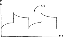
FIG. 1C is a graph of the output power P of the generator shown in FIG. 1A versus time under the same conditions as FIG. 1B;
FIG. 2A is a block diagram of a generator connected with a nonlinear load in accordance with an illustrative embodiment of the invention;
FIG. 2B is a block diagram of a compensation subsystem of a generator in accordance with an illustrative embodiment of the present invention;
FIG. 3 is a flowchart of a method for correcting interactions between a generator and a nonlinear load in accordance with an illustrative embodiment of the invention;
FIG. 4 is a block diagram of a generator connected with a nonlinear load in accordance with another illustrative embodiment of the invention;
FIG. 5A illustrates a simplified Smith chart showing the generator control signal C required for each of a set of load impedances for a particular output power P0, according to an illustrative embodiment of the invention;
FIG. 5B illustrates a simplified Smith chart showing the compensation signal K for each of a set of load impedances for the same output power P0 as in FIG. 5A, according to an illustrative embodiment of the invention;
FIG. 6 is a flow chart of a method for correcting interactions between a generator and a nonlinear load in accordance with another illustrative embodiment of the invention;
FIG. 7 is a block diagram of a generator connected to a nonlinear load in accordance with yet another illustrative embodiment of the invention;
fig. 8 is a circuit diagram of a power amplifier including both a main control input and an auxiliary control input in accordance with an illustrative embodiment of the present invention; and
FIG. 9 is a flowchart of a method for correcting interactions between a generator and a nonlinear load in accordance with yet another illustrative embodiment of the invention.
Detailed Description
Understanding various embodiments of the present invention is aided by analyzing how interactions between the generator and the impedance of a nonlinear load connected to the generator can lead to instability in the output power of the generator. Fig. 1A is a block diagram of a generator 100 connected with a nonlinear load 105 to assist in this analysis. The generator 100 includes a power amplifier 110, the power amplifier 110 delivering an output power P115 to the nonlinear load 105. The nonlinear load 105 in turn presents an impedance Z to the power amplifier 110, the real and imaginary parts of which are a resistance R120 and a reactance X125, respectively. Namely, Z ═ R + jX.
The power amplifier 110 comprises a control input 130 receiving a control signal C135. The control signal 135 is used to control the output power 115 produced by the power amplifier 110. Control signal 135 is generated by a main power control loop (not shown in fig. 1A).
Assuming that changes in generator output power 115 occur instantaneously in response to changes in the impedance of the nonlinear load 105, and similarly, changes in the impedance of the nonlinear load 105 occur instantaneously as the output power 115 delivered into the nonlinear load 105 changes, the system shown in FIG. 1A can be modeled by the following three equations:
P=f(C,R,X)
R=g(P)
X=h(P)
assuming that these functions are differentiable and use taylor series expansions with only first derivatives, they can be linearized around the operating point, thus obtaining
Wherein, is a vector
<math>
<mrow>
<mfrac>
<mi>dP</mi>
<mi>dZ</mi>
</mfrac>
<mo>=</mo>
<mrow>
<mo>(</mo>
<mfrac>
<mrow>
<mo>∂</mo>
<mi>f</mi>
</mrow>
<mrow>
<mo>∂</mo>
<mi>R</mi>
</mrow>
</mfrac>
<mo>,</mo>
<mfrac>
<mrow>
<mo>∂</mo>
<mi>f</mi>
</mrow>
<mrow>
<mo>∂</mo>
<mi>X</mi>
</mrow>
</mfrac>
<mo>)</mo>
</mrow>
</mrow>
</math>
And the inner product of (d). The first of these vectors models the sensitivity of the generator 100 to changes in the impedance of the nonlinear load 105, while the second vector models the sensitivity of the impedance of the nonlinear load 105 to changes in the generator power 115.
As long as the inner product is less than 1, the decrease in gain of the main power control loop of the generator 100 may compensate for the increase in gain of the output power 115 with respect to the control signal 135. However, when the inner product is greater than 1, the sign of the transfer function from the control signal 135 to the output power 115 is reversed and any modification of the gain of the main power control loop of the generator cannot restore stability. In an unstable condition, the generator 100 does not produce the desired constant output power 115.
Instability due to interaction between the generator 100 and the nonlinear load 105 is illustrated in fig. 1B. FIG. 1B shows a generatorGraph 140 of the relationship between P and control signal C135 when the output power P115 of 100 is unstable. Note that graph 140 is not one-to-one (i.e., it is a relationship rather than a function). That is, for some values of C, there are multiple P values. For being C1(145) P first at point 150, but P subsequently falls to point 155. By changing control signal 135 to C2(160) Compensating for the decrease in output power 115 first produces P at point 165, but P then jumps up to point 170. In some applications, the transition from point 150 to 155 or from point 165 to point 170 may occur in as little as 2-3 microseconds.
The output power 115 produced by the generator 100 is plotted against time as a graph 175 in fig. 1C.
Reference is now made to fig. 2A, which is a block diagram of a generator 200 connected with a nonlinear load 205 in accordance with an illustrative embodiment of the present invention. The generator 200 includes some sort of "engine". Examples of "engines" include, but are not limited to, power amplifiers and converters. In the particular embodiment illustrated in fig. 2A, the generator 200 includes a power amplifier 210 that delivers an output power P215 to a nonlinear load 205. In one embodiment, the generator 200 is a Radio Frequency (RF) generator with a high reactive source impedance and the nonlinear load 205 includes plasma in addition to, for example, matching networks and cables. Such systems may be used in, for example, vapor deposition and etching applications. The nonlinear load 205 presents a complex impedance Z to the power amplifier 210 having real and imaginary parts, respectively, a resistance R220 and a reactance X225 (Z ═ R + jX).
The power amplifier 210 comprises a control input 230 to which a main control signal C235 is fed. For example, in one embodiment, main control signal 235 is a voltage. Generally, main control signal 235 is used to control the output power, output voltage, output current, or any combination thereof, delivered by generator 200 to nonlinear load 205. Main control signal 235 is generated by a main power control loop (not shown in fig. 2A). For example, in one typical implementation of a main power control loop, the feedback power measured at the load and the power setpoint (desired output power 215) are fed to the input of a differential amplifier whose output (error signal) is main control signal 235.
The compensation subsystem 240 measures the impedance of the nonlinear load 205 and generates a compensation signal K245 that corresponds to (depends on) the measured load impedance. The compensation signal 245 fed to the power amplifier 210 makes the transfer function of the output power 215 of the generator 200 with respect to the main control signal 235 substantially insensitive to changes in the impedance of the nonlinear load 205. The result is a system that is stabilized by linearizing the output power 215 associated with main control signal 235. The compensation signal 245 for a given measured load impedance varies according to particular embodiments.
FIG. 2B is a block diagram of compensation subsystem 240, according to an illustrative embodiment of the invention. The compensation subsystem 240 includes an impedance measurement circuit 250 that outputs a measured load impedance 255, and a compensation signal generation circuit 260 that generates a compensation signal 245.
The compensation signal 245 may be predetermined by appropriate calibration such as the following steps. First, the generator 200 is connected to a test load (e.g., a tuned circuit) having an adjustable impedance. The load is first set to a nominal reference impedance (e.g., 50 ohms) at which the generator 200 is designed to operate. Second, the desired power setpoint P0Is input to the generator 200 and stabilizes the generator 200 at the output power P0. Third, main control signal 235 is maintained (fixed) in generating output power P0To the current value in the reference impedance. Fourth, the load impedance is changed and recorded to be maintained at P in the case of the changed load impedance0The required compensation signal 245 of the output power 215. The fourth step is then repeated for as many values of load impedance as desired. The entire calibration process described above is repeated for many different output power setpoints as desired.
In the illustrative embodiment, compensation subsystem 240 is implemented using high-speed digital algorithms in a field referred to by those skilled in the art as the "reflection coefficient field". In one embodiment, the compensation subsystem 240 is implemented in a Field Programmable Gate Array (FPGA), for example, along with other functions of the generator 200. In other embodiments, compensation subsystem 240 is implemented using a processor executing firmware or software. In general, the functionality of compensation subsystem 240 may be implemented in hardware, firmware, software, or a combination thereof.
In the illustrative embodiment, the impedance measurement circuit 250 is capable of measuring the impedance of the nonlinear load 205 approximately once every millisecond, which eliminates instability-related frequencies below approximately 500 kHz. The sampling rate is lower or higher in other embodiments.
In one embodiment, the compensation signal generation circuit 260 includes a look-up table for each of the plurality of output power levels 215. Each look-up table for a given output power 215 maps each of a set of discrete values of the measured load impedance 255 to a corresponding discrete value of the compensation signal 245. In this embodiment, the compensation signal generation circuit 260 includes a digital-to-analog (D/a) converter (not shown in fig. 2B) to produce the analog compensation signal 245.
In some embodiments, the calibration process for a given output power level is performed for only a few points (e.g., four load impedance values different from the reference impedance that bracket the reference impedance on the smith chart). For other values of the measured load impedance 255, the compensation signal K may be obtained from those few stored values by, for example, interpolation. In some embodiments, the slope (gradient) of the compensation signal 245 associated with the measured load impedance 255 is stored in a look-up table, and the compensation signal 245 for a particular measured load impedance 255 is interpolated by multiplying the appropriate slope by the difference between the measured load impedance 255 and the reference impedance. Further, in some embodiments, fast numerical algorithms such as successive approximation are used to perform mathematical operations such as division to increase the speed of the compensation subsystem 240.
FIG. 3 is a block diagram for use in accordance with an illustrative embodiment of the present inventionA flow chart of a method of correcting for interactions between a generator and a nonlinear load. At 305, the power amplifier 210 receives a main control signal 235 at a control input 230. At 310, the impedance measurement circuit 250 measures the impedance 255 of the nonlinear load 205. At 315, the compensation signal generation circuit 260 produces a compensation signal 245 that is fed to the power amplifier 210. Compensation signal 245 renders the transfer function of output power 215 of generator 200 with respect to main control signal 235 substantially insensitive to changes in the impedance of nonlinear load 205. Thus, compensation signal 245 combined with main control signal 235 causes generator 200 to maintain a stable (substantially constant) output power 215 at a desired level P even though the impedance of nonlinear load 205 changes0. At 320, the process ends.
Fig. 4 is a block diagram of a generator 400 connected with a nonlinear load 205 in accordance with another illustrative embodiment of the invention. The generator 400 includes a power amplifier 405 having a control input 410. The compensation subsystem 415 generates a compensation signal K420, which compensation signal K420 is fed to a summing circuit 430 along with a main control signal 425. The output of the summing circuit 430 is fed to a control input 410. As with the embodiment discussed above in connection with fig. 2A-3, the compensation signal 420 has the following effects: the transfer function of the output power 215 of the generator 400 with respect to the main control signal 425 is made substantially insensitive to changes in the impedance of the nonlinear load 205 to prevent instability in the output power 215 that would otherwise result from the interaction between the impedances of the generator 400 and the nonlinear load 205.
FIG. 5A illustrates a simplified Smith chart 500 showing for a particular output power P, according to an illustrative embodiment of the invention0(215) Each of a set of load impedances is a desired power amplifier control signal at a control input 410. In the hypothetical example of FIG. 5A, the desired 100W (Watt) output power level (P) delivered into 50 ohms (reference impedance) is produced0) The required main control signal 425 is 20V. The reference impedance corresponds to point 505 at the center of the smith chart 500. Points 510, 515, 520, and 525 correspond to reference impedances505 measure load impedance 255 differently. The desired output power P generated for each of these impedances is shown on a simplified Smith chart 5000The control signal required at control input 410. These different values of the control signal required at the control input 410 in relation to the load impedance may be determined by, for example, the calibration procedure described above and stored in a look-up table to which the compensation signal generation circuit 260 has access.
FIG. 5B illustrates a simplified Smith chart 530 showing the same desired output power P for an illustrative embodiment of the invention0A compensation signal K420 corresponding to each of a set of load impedances (505, 510, 515, 520, and 525) plotted in fig. 5A. In this particular embodiment, the compensation signal 420 is the difference between the following control signals: a control signal causes the generator 400 to produce a P when the impedance of the nonlinear load 205 is the measured impedance0The specific output power 215; while the other control signal causes the generator 400 to produce the same output power P0To be fed into the reference impedance. The difference is plotted on the simplified smith chart 530 for each of the points 505, 510, 515, 520 and 525.
The sum produced by summing circuit 430, the sum of main control signal 425 and compensation signal 420, is thus the control signal at control output 410, which causes power amplifier 405 to produce the desired output power P for substantially the same main control signal value 4250To the measured load impedance 255 regardless of the load impedance, thus making the main control signal 425 insensitive to changes in the impedance of the nonlinear load 205. Of course, when the measured load impedance 255 is the reference impedance (point 505 in fig. 5B), the compensation signal 420 is zero.
FIG. 6 is a flowchart of a method for correcting interactions between a generator and a nonlinear load in accordance with another illustrative embodiment of the invention. At 310, the impedance measurement circuit 250 measures the impedance 255 of the nonlinear load 205. At 605, the sum of the main control signal 425 and the compensation signal 420 is fed to the control input 410 of the power amplifier 405, the compensation signal 420 being a controlDifference between signals: a control signal causes the generator 400 to produce a P when the impedance of the nonlinear load 205 is the measured impedance0The specific output power 215; while the other control signal causes the generator 400 to produce the same output power P0To be fed into the reference impedance. The result is to prevent instability of the output power 215 that would otherwise result from the interaction between the impedances of the generator 400 and the nonlinear load 205. The process ends at 610.
Fig. 7 is a block diagram of a generator 700 connected with a nonlinear load 205 in accordance with yet another illustrative embodiment of the present invention. In this embodiment, power amplifier 705 includes both a primary control input 710 and a secondary control input 715. The master control input 710 receives a master control signal C730.
The compensation subsystem 720 generates a specially processed compensation signal 725 for connection to the auxiliary control input 715. Note that the particular compensation signal 725 that is related to the load impedance depends on the design of the power amplifier 705. However, regardless of how power amplifier 705 is designed, a calibration procedure such as that described above may be performed to provide a given desired output power P0In this case, a compensation signal 725 for each of a set of values of the measured load impedance 255 is determined.
The combination of the main control signal 730 and the compensation signal 725 causes the power amplifier 705 to produce the desired output power P0Regardless of the change in impedance of the nonlinear load 205. In other words, compensation signal 725 makes the transfer function of the output power 215 of generator 700 with respect to the main control signal 730 substantially insensitive to changes in the impedance of nonlinear load 205, thereby stabilizing the output power 215 of generator 700 with respect to the main control signal 730.
Fig. 8 is a circuit diagram of a power amplifier 705 that includes both a main control input 710 and an auxiliary control input 715, respectively, in accordance with an illustrative embodiment of the invention. In fig. 8, a primary control input 710 (voltage in this example) is connected to a choke (choke) 805. A resonant circuit comprising an inductor 810 and a capacitor 815 is connected between the other node of the choke 805 and the nonlinear load 205. The oscillator 820 is connected to a capacitor 825, and another node of the capacitor 825 is connected to a gate of a Metal Oxide Semiconductor Field Effect Transistor (MOSFET) 830. In this particular embodiment, the auxiliary control input 715 is a bias input in series with a choke 835, the other node of the choke 835 being connected between the node of the capacitor 825 and the gate of the MOSFET 830. Fig. 8 is merely one example of an auxiliary control input 715. In other embodiments, the auxiliary control input 715 is different from the bias input example shown in fig. 8.
FIG. 9 is a flowchart of a method for correcting interactions between a generator and a nonlinear load in accordance with yet another illustrative embodiment of the invention. At 905, power amplifier 705 receives a primary control signal 730 at its primary control input 710. At 310, the impedance measurement circuit 250 measures the impedance 255 of the nonlinear load 205. At 910, the compensation subsystem 720 feeds a compensation signal 725 to the auxiliary input 715 of the power amplifier 705, the compensation signal 725 making the transfer function of the output power 215 of the generator 700 with respect to the main control signal 730 substantially insensitive to changes in the impedance of the nonlinear load 205, thereby preventing instability in the output power 215 that would otherwise result from interactions between the impedances of the generator 700 and the nonlinear load 205.
In some embodiments, the compensation signal effectively causes the inner product in equation 1 above to be 0. That is, the compensation signal eliminates the sensitivity of the power amplifier to changes in the impedance of the non-linear load. In other embodiments, the inner product in equation 1 may be made other than 0 by applying additional compensation to the power amplifier by the compensation signal, such that the impedances of the power amplifier and the nonlinear load affect each other in a particular desired manner. In some embodiments, this additional compensation may be specified by a user of the generator to achieve a desired interplay between the generator and the nonlinear load. This additional compensation may provide additional stability beyond that provided by, for example, simply eliminating the sensitivity of the power amplifier to changes in load impedance.
In summary, the present invention generally provides methods and apparatus for correcting interactions between a generator and a nonlinear load. Those skilled in the art can readily recognize that many modifications and substitutions may be made to the present invention and its uses and configurations to achieve substantially the same results as achieved by the embodiments described herein. Therefore, it is not intended to limit the invention to the exemplary forms disclosed. Many variations, modifications and alternative constructions fall within the scope and spirit of the disclosed invention as expressed in the claims.
Claims (23)
1. A method for correcting interactions between a generator and a nonlinear load connected to an output of the generator, the method comprising:
receiving a main control signal at a control input of an engine of the generator, the main control signal controlling at least one of an output power, an output current, and an output voltage delivered by the generator to the nonlinear load, the engine being one of a power amplifier and a converter;
measuring an impedance of the nonlinear load; and
feeding the generator with a compensation signal corresponding to the measured impedance, the compensation signal making a transfer function of the output power of the generator with respect to the main control signal substantially insensitive to changes in the impedance of the nonlinear load to stabilize the output power of the generator.
2. The method of claim 1, wherein the sum of the main control signal and the compensation signal is fed to the control input.
3. The method of claim 2, wherein the compensation signal is a difference between: a control signal causing the generator to produce a specific output power when the impedance of the nonlinear load is the measured impedance; and another control signal causes the generator to produce the particular output power for delivery into a reference impedance.
4. The method of claim 1, wherein the compensation signal is fed to an auxiliary control input of the engine separate from the control input.
5. The method of claim 4, wherein the auxiliary control input is a bias input.
6. The method of claim 1, wherein the compensation signal causes the generator to interact with the impedance of the nonlinear load in a user-specified manner in addition to rendering a transfer function of the output power of the generator with respect to the main control signal substantially insensitive to changes in the impedance of the nonlinear load.
7. The method of claim 1, wherein the generator is a radio frequency generator.
8. The method of claim 1, wherein the non-linear load comprises a plasma.
9. A method for correcting interactions between a generator and a nonlinear load connected to an output of the generator, the method comprising:
measuring an impedance of the nonlinear load; and
feeding a control input of an engine of the generator, the engine being one of a power amplifier and a converter, with a sum of a main control signal and a compensation signal,
the main control signal controls at least one of an output power, an output current, and an output voltage delivered by the generator to the non-linear load,
the compensation signal depends on the measured impedance, the compensation signal being the difference between the following control signals: a control signal causing the generator to produce a specific output power when the impedance of the nonlinear load is the measured impedance; and another control signal causes the generator to produce the specific output power for delivery into a reference impedance,
the compensation signal renders the transfer function of the output power of the generator with respect to the main control signal substantially insensitive to changes in the impedance of the nonlinear load to prevent instability in the output power that would otherwise result from interactions between the impedances of the generator and the nonlinear load.
10. A method for correcting interactions between a generator and a nonlinear load connected to an output of the generator, the method comprising:
receiving a master control signal at a master control input of an engine of the generator, the master control signal controlling at least one of an output power, an output current, and an output voltage delivered by the generator to the nonlinear load, the engine being one of a power amplifier and a converter;
measuring an impedance of the nonlinear load; and
feeding an auxiliary control input of the engine separate from the main control input with a compensation signal that depends on the measured impedance, the compensation signal making a transfer function of the output power of the generator with respect to the main control signal substantially insensitive to changes in the impedance of the nonlinear load to prevent instability in the output power that would otherwise result from interactions between the impedances of the generator and the nonlinear load.
11. An electrical generator comprising:
an engine comprising a control input configured to receive a main control signal controlling at least one of an output power, an output current, and an output voltage delivered by the generator to a nonlinear load connected to an output of the generator, the engine being one of a power amplifier and a converter; and the number of the first and second groups,
a compensation subsystem, comprising:
an impedance measurement circuit that measures an impedance of the nonlinear load; and
a compensation signal generation circuit that feeds the generator with a compensation signal corresponding to the measured impedance, the compensation signal making a transfer function of the output power of the generator with respect to the main control signal substantially insensitive to changes in the impedance of the nonlinear load to stabilize the output power of the generator.
12. The generator of claim 11, further comprising:
a summing circuit having at least a first input receiving said main control signal and a second input receiving said compensation signal and an output, the output of said summing circuit being connected to said control input, said summing circuit producing at its output the sum of said main control signal and said compensation signal.
13. The generator of claim 12, wherein the compensation signal is a difference between: a control signal causing the generator to produce a specific output power when the impedance of the nonlinear load is the measured impedance; and another control signal causes the generator to produce the particular output power for delivery into a reference impedance.
14. The generator of claim 11, wherein the engine further comprises an auxiliary control input separate from the control input, the auxiliary control input receiving the compensation signal.
15. The generator of claim 14 wherein the auxiliary control input is a bias input.
16. The generator of claim 11, wherein the compensation signal causes the generator to interact with the impedance of the nonlinear load in a user-specified manner in addition to rendering a transfer function of the generator's output power with respect to the main control signal substantially insensitive to changes in the impedance of the nonlinear load.
17. The generator of claim 11, wherein the generator is a radio frequency generator.
18. The generator of claim 11, wherein the nonlinear load comprises a plasma.
19. The electrical generator of claim 11, wherein the compensation signal generation circuit comprises a look-up table for each of a plurality of output power levels that maps a set of discrete values of the measured impedance to a corresponding set of discrete values of the compensation signal.
20. The generator of claim 11, wherein a source impedance of the generator is substantially different from a complex conjugate of a reference load impedance.
21. The generator of claim 20 wherein the reference load impedance is 50 ohms.
22. An electrical generator comprising:
an engine comprising a control input, the engine being one of a power amplifier and a converter;
a compensation subsystem, comprising:
an impedance measurement circuit that measures an impedance of a nonlinear load connected to an output of the generator; and
a compensation signal generation circuit that generates a compensation signal that depends on the measured impedance; and
a summing circuit having at least a first input receiving a main control signal controlling at least one of output power, output current and output voltage delivered by the generator to the nonlinear load and a second input receiving the compensation signal, the output of the summing circuit being connected to the control input, the summing circuit producing at its output the sum of the main control signal and the compensation signal,
the compensation signal is the difference between the following control signals: a control signal causing the generator to produce a specific output power when the impedance of the nonlinear load is the measured impedance; and another control signal causes the generator to produce the specific output power for delivery into a reference impedance,
the compensation signal renders the transfer function of the output power of the generator with respect to the main control signal substantially insensitive to changes in the impedance of the nonlinear load to prevent instability in the output power that would otherwise result from interactions between the impedances of the generator and the nonlinear load.
23. An electrical generator comprising:
an engine comprising a primary control input and a secondary control input, the primary control input receiving a primary control signal controlling at least one of an output power, an output current, and an output voltage delivered by the generator to a non-linear load connected to an output of the generator, the engine being one of a power amplifier and a converter; and
a compensation subsystem, comprising:
an impedance measurement circuit that measures an impedance of the nonlinear load; and
a compensation signal generation circuit that feeds the auxiliary control input with a compensation signal that depends on the measured impedance, the compensation signal making a transfer function of the output power of the generator with respect to the main control signal substantially insensitive to changes in the impedance of the nonlinear load to prevent instability in the output power that would otherwise result from interactions between the impedances of the generator and the nonlinear load.
Applications Claiming Priority (3)
| Application Number | Priority Date | Filing Date | Title |
|---|---|---|---|
| US11/740,710 | 2007-04-26 | ||
| US11/740,710 US7570028B2 (en) | 2007-04-26 | 2007-04-26 | Method and apparatus for modifying interactions between an electrical generator and a nonlinear load |
| PCT/US2008/061232 WO2008134344A1 (en) | 2007-04-26 | 2008-04-23 | Method and apparatus for modifying interactions between an electrical generator and a nonlinear load |
Publications (1)
| Publication Number | Publication Date |
|---|---|
| CN101688890A true CN101688890A (en) | 2010-03-31 |
Family
ID=39888009
Family Applications (1)
| Application Number | Title | Priority Date | Filing Date |
|---|---|---|---|
| CN200880017443A Pending CN101688890A (en) | 2007-04-26 | 2008-04-23 | Method and apparatus for modifying interactions between an electrical generator and a nonlinear load |
Country Status (6)
| Country | Link |
|---|---|
| US (2) | US7570028B2 (en) |
| JP (1) | JP5414071B2 (en) |
| KR (1) | KR101239139B1 (en) |
| CN (1) | CN101688890A (en) |
| TW (1) | TWI338782B (en) |
| WO (1) | WO2008134344A1 (en) |
Cited By (1)
| Publication number | Priority date | Publication date | Assignee | Title |
|---|---|---|---|---|
| CN111357076A (en) * | 2017-10-11 | 2020-06-30 | 先进能源工业公司 | Method and apparatus for varying the apparent source impedance of a generator |
Families Citing this family (16)
| Publication number | Priority date | Publication date | Assignee | Title |
|---|---|---|---|---|
| US7948215B2 (en) * | 2007-04-19 | 2011-05-24 | Hadronex, Inc. | Methods and apparatuses for power generation in enclosures |
| US7570028B2 (en) * | 2007-04-26 | 2009-08-04 | Advanced Energy Industries, Inc. | Method and apparatus for modifying interactions between an electrical generator and a nonlinear load |
| US8289029B2 (en) * | 2008-02-14 | 2012-10-16 | Mks Instruments, Inc. | Application of wideband sampling for arc detection with a probabilistic model for quantitatively measuring arc events |
| US8334700B2 (en) * | 2008-02-14 | 2012-12-18 | Mks Instruments, Inc. | Arc detection |
| US8264237B2 (en) * | 2008-02-14 | 2012-09-11 | Mks Instruments, Inc. | Application of wideband sampling for arc detection with a probabilistic model for quantitatively measuring arc events |
| DE102008059428A1 (en) * | 2008-11-27 | 2010-06-10 | Diehl Ako Stiftung & Co. Kg | Energieeinspeisevorrichtung |
| US8344704B2 (en) * | 2008-12-31 | 2013-01-01 | Advanced Energy Industries, Inc. | Method and apparatus for adjusting the reference impedance of a power generator |
| US8716984B2 (en) * | 2009-06-29 | 2014-05-06 | Advanced Energy Industries, Inc. | Method and apparatus for modifying the sensitivity of an electrical generator to a nonlinear load |
| US8330432B2 (en) * | 2009-12-22 | 2012-12-11 | Advanced Energy Industries, Inc | Efficient active source impedance modification of a power amplifier |
| US8314561B2 (en) | 2010-04-02 | 2012-11-20 | Mks Instruments, Inc. | Multi-channel radio frequency generator |
| TWI479159B (en) * | 2013-08-13 | 2015-04-01 | Nat Univ Tsing Hua | Method for estimating voltage stability |
| EP3314723B1 (en) * | 2015-06-29 | 2019-06-12 | ABB Schweiz AG | Ups with source impedance compensation |
| CN106771556B (en) * | 2016-12-23 | 2019-02-22 | 中国计量科学研究院 | A system and method for differential measurement of AC power based on quantum technology |
| US10727671B2 (en) | 2017-08-08 | 2020-07-28 | Solar Turbines Incorporated | Gas turbine electrical power system and control strategy for limiting reverse power shutdown |
| CN117999631A (en) * | 2021-09-17 | 2024-05-07 | 朗姆研究公司 | Reference box for direct drive type radio frequency power supply source |
| US11972926B2 (en) * | 2021-10-05 | 2024-04-30 | Advanced Energy Industries, Inc. | Dynamic control-setpoint modification |
Family Cites Families (42)
| Publication number | Priority date | Publication date | Assignee | Title |
|---|---|---|---|---|
| US4160397A (en) * | 1977-10-17 | 1979-07-10 | Milo Bertini | Saw blade construction and method of making same |
| US4478130A (en) * | 1981-03-19 | 1984-10-23 | Sundstrand Corporation | Arrangement for slipper cavitation erosion control and impact reduction |
| US4463306A (en) * | 1981-09-11 | 1984-07-31 | Power Technologies, Inc. | System for stabilizing synchronous machines |
| US4387777A (en) * | 1981-10-26 | 1983-06-14 | Willo Partners | Calorie counting method and apparatus |
| FR2525680A1 (en) * | 1982-04-26 | 1983-10-28 | Dumenil Claude | AUTOMATIC ACTUATING SEALING DEVICE FOR CLOSURES OF BUILDINGS, ESPECIALLY DOORS AND WINDOWS |
| US4462942A (en) * | 1982-07-30 | 1984-07-31 | Eli Lilly And Company | A47934 Antibiotic and process for production thereof |
| US4496899A (en) * | 1983-06-28 | 1985-01-29 | General Electric Company | Control for a force commutated current source var generator |
| JPS6221222A (en) * | 1985-07-19 | 1987-01-29 | Matsushita Electric Ind Co Ltd | Light-exposing device |
| US4770097A (en) * | 1986-07-04 | 1988-09-13 | General Mining Union Corporation Limited | Mining method with no delay between shot initiator and firing |
| US4704443A (en) * | 1986-10-27 | 1987-11-03 | Dow Corning Corporation | Method of reducing activity of silicone polymers |
| US4779924A (en) * | 1987-08-19 | 1988-10-25 | Rudel Myron G | Seat for a motorcycle |
| JPH03222508A (en) * | 1990-01-26 | 1991-10-01 | Onkyo Corp | Amplifier circuit |
| DE69304522T2 (en) * | 1992-04-16 | 1997-01-23 | Advanced Energy Ind Inc | STABILIZER FOR SWITCHING MODE PROVIDED RADIO FREQUENCY PLASMA DEVICE |
| US5483147A (en) * | 1992-07-10 | 1996-01-09 | Massachusetts Institute Of Technology | Decentralized excitation control for an electrical power utility system |
| US5817093A (en) * | 1993-07-22 | 1998-10-06 | Ethicon Endo-Surgery, Inc. | Impedance feedback monitor with query electrode for electrosurgical instrument |
| US5481914A (en) * | 1994-03-28 | 1996-01-09 | The Charles Stark Draper Laboratory, Inc. | Electronics for coriolis force and other sensors |
| US5576629A (en) * | 1994-10-24 | 1996-11-19 | Fourth State Technology, Inc. | Plasma monitoring and control method and system |
| JP2845163B2 (en) * | 1994-10-27 | 1999-01-13 | 日本電気株式会社 | Plasma processing method and apparatus |
| US5710492A (en) * | 1994-12-22 | 1998-01-20 | Hitachi, Ltd. | Apparatus for monitoring and stabilizing power swing in a power system by utilizing a power electronics technique |
| US5618758A (en) * | 1995-02-17 | 1997-04-08 | Sharp Kabushiki Kaisha | Method for forming a thin semiconductor film and a plasma CVD apparatus to be used in the method |
| KR970064327A (en) * | 1996-02-27 | 1997-09-12 | 모리시다 요이치 | High frequency power applying device, plasma generating device, plasma processing device, high frequency power applying method, plasma generating method and plasma processing method |
| KR0183844B1 (en) * | 1996-04-30 | 1999-05-15 | 김광호 | Rf generator and pulse plasma using it |
| US6214162B1 (en) * | 1996-09-27 | 2001-04-10 | Tokyo Electron Limited | Plasma processing apparatus |
| JP3042450B2 (en) * | 1997-06-24 | 2000-05-15 | 日本電気株式会社 | Plasma processing method |
| US6045877A (en) * | 1997-07-28 | 2000-04-04 | Massachusetts Institute Of Technology | Pyrolytic chemical vapor deposition of silicone films |
| US6187685B1 (en) * | 1997-08-01 | 2001-02-13 | Surface Technology Systems Limited | Method and apparatus for etching a substrate |
| US6218196B1 (en) * | 1998-05-06 | 2001-04-17 | Mitsubishi Denki Kabushiki Kaisha | Etching apparatus, etching method, manufacturing method of a semiconductor device, and semiconductor device |
| US6126778A (en) * | 1998-07-22 | 2000-10-03 | Micron Technology, Inc. | Beat frequency modulation for plasma generation |
| US5985375A (en) * | 1998-09-03 | 1999-11-16 | Micron Technology, Inc. | Method for pulsed-plasma enhanced vapor deposition |
| US5977737A (en) * | 1998-09-09 | 1999-11-02 | Labriola, Ii; Donald P. | Digital motor driver circuit and method |
| JP2000100790A (en) * | 1998-09-22 | 2000-04-07 | Canon Inc | Plasma treating unit and treatment method using the same |
| JP3533105B2 (en) * | 1999-04-07 | 2004-05-31 | Necエレクトロニクス株式会社 | Semiconductor device manufacturing method and manufacturing apparatus |
| KR100321728B1 (en) * | 1999-06-30 | 2002-01-26 | 박종섭 | Method for forming feram by using plasma pulse |
| KR100292412B1 (en) * | 1999-07-14 | 2001-06-01 | 윤종용 | Method for enhancing etching selectivity of metal silicide film/polysilicon film and method for etching stacked film of metal silicide film and polysilicon film using the same |
| US6459066B1 (en) * | 2000-08-25 | 2002-10-01 | Board Of Regents, The University Of Texas System | Transmission line based inductively coupled plasma source with stable impedance |
| US6416822B1 (en) * | 2000-12-06 | 2002-07-09 | Angstrom Systems, Inc. | Continuous method for depositing a film by modulated ion-induced atomic layer deposition (MII-ALD) |
| US6459067B1 (en) * | 2001-04-06 | 2002-10-01 | Eni Technology, Inc. | Pulsing intelligent RF modulation controller |
| JP2003008365A (en) * | 2001-04-16 | 2003-01-10 | Matsushita Electric Ind Co Ltd | Circuit for power amplification, control method of circuit for power amplification and portable terminal device |
| US6696820B2 (en) * | 2001-10-30 | 2004-02-24 | Delphi Technologies, Inc. | Alternating current generator field regulation control |
| US6703080B2 (en) * | 2002-05-20 | 2004-03-09 | Eni Technology, Inc. | Method and apparatus for VHF plasma processing with load mismatch reliability and stability |
| WO2006070809A1 (en) * | 2004-12-27 | 2006-07-06 | Daihen Corporation | High frequency power supply |
| US7570028B2 (en) * | 2007-04-26 | 2009-08-04 | Advanced Energy Industries, Inc. | Method and apparatus for modifying interactions between an electrical generator and a nonlinear load |
-
2007
- 2007-04-26 US US11/740,710 patent/US7570028B2/en active Active
-
2008
- 2008-04-23 WO PCT/US2008/061232 patent/WO2008134344A1/en active Application Filing
- 2008-04-23 CN CN200880017443A patent/CN101688890A/en active Pending
- 2008-04-23 JP JP2010506447A patent/JP5414071B2/en active Active
- 2008-04-23 KR KR1020097022972A patent/KR101239139B1/en active IP Right Grant
- 2008-04-25 TW TW097115193A patent/TWI338782B/en active
-
2009
- 2009-06-29 US US12/494,026 patent/US8004251B2/en active Active
Cited By (2)
| Publication number | Priority date | Publication date | Assignee | Title |
|---|---|---|---|---|
| CN111357076A (en) * | 2017-10-11 | 2020-06-30 | 先进能源工业公司 | Method and apparatus for varying the apparent source impedance of a generator |
| CN111357076B (en) * | 2017-10-11 | 2023-03-21 | 先进能源工业公司 | Method and apparatus for varying the apparent source impedance of a generator |
Also Published As
| Publication number | Publication date |
|---|---|
| US20090278598A1 (en) | 2009-11-12 |
| TWI338782B (en) | 2011-03-11 |
| US8004251B2 (en) | 2011-08-23 |
| WO2008134344A1 (en) | 2008-11-06 |
| KR20100016176A (en) | 2010-02-12 |
| US7570028B2 (en) | 2009-08-04 |
| JP5414071B2 (en) | 2014-02-12 |
| KR101239139B1 (en) | 2013-03-08 |
| TW200912328A (en) | 2009-03-16 |
| JP2010525754A (en) | 2010-07-22 |
| US20080270048A1 (en) | 2008-10-30 |
Similar Documents
| Publication | Publication Date | Title |
|---|---|---|
| CN101688890A (en) | Method and apparatus for modifying interactions between an electrical generator and a nonlinear load | |
| US9225299B2 (en) | Variable-class amplifier, system, and method | |
| EP3695435B1 (en) | Matched source impedance driving system and method of operating the same | |
| KR100362598B1 (en) | Electrically tuned matching network using predictor-corrector control systems | |
| EP0412568B1 (en) | Matching network and method for using same | |
| EP1702344B1 (en) | Stabilizing plasma and generator interactions | |
| JP6084417B2 (en) | Impedance adjustment device | |
| EP2517360B1 (en) | Efficient active source impedance modification of a power amplifier | |
| US20210118650A1 (en) | Inter-period control system for plasma power delivery system and method of operating same | |
| Zhang et al. | Control of ion energy distributions using phase shifting in multi-frequency capacitively coupled plasmas | |
| JP4011363B2 (en) | Controller for radio frequency power generator with reduced cable length sensitivity | |
| JPH0620793A (en) | Inductive coupling plasma generator | |
| EP1831990B1 (en) | Load mismatch adaptation in coupler-based amplifiers | |
| CN101079600B (en) | Regulator for high frequency amplifier | |
| RU2377716C2 (en) | Electronic circuit | |
| KR20220083721A (en) | Determination of Optimal Ion Energy for Plasma Treatment of Dielectric Substrates | |
| KR100907239B1 (en) | Accelerator high frequency control method | |
| JP6485923B2 (en) | Method for adjusting impedance of high-frequency matching system | |
| KR20040084079A (en) | Apparatus and method for matching an radio frequency | |
| CN118783961A (en) | Analog signal generating device and calibration method thereof | |
| KR20070031452A (en) | Digital transmitter system and adaptive controller using self-generated predistortion parameter lists | |
| CN118870629A (en) | A frequency modulation mechanism of all-solid-state plasma radio frequency generator and frequency modulation method thereof |
Legal Events
| Date | Code | Title | Description |
|---|---|---|---|
| C06 | Publication | ||
| PB01 | Publication | ||
| C10 | Entry into substantive examination | ||
| SE01 | Entry into force of request for substantive examination | ||
| C02 | Deemed withdrawal of patent application after publication (patent law 2001) | ||
| WD01 | Invention patent application deemed withdrawn after publication |
Application publication date: 20100331 |