CN101673397A - Digital camera nonlinear calibration method based on LCDs - Google Patents
Digital camera nonlinear calibration method based on LCDs Download PDFInfo
- Publication number
- CN101673397A CN101673397A CN200910019528A CN200910019528A CN101673397A CN 101673397 A CN101673397 A CN 101673397A CN 200910019528 A CN200910019528 A CN 200910019528A CN 200910019528 A CN200910019528 A CN 200910019528A CN 101673397 A CN101673397 A CN 101673397A
- Authority
- CN
- China
- Prior art keywords
- image
- calibration
- distortion
- camera
- pixel
- Prior art date
- Legal status (The legal status is an assumption and is not a legal conclusion. Google has not performed a legal analysis and makes no representation as to the accuracy of the status listed.)
- Granted
Links
- 238000000034 method Methods 0.000 title claims abstract description 55
- 230000003287 optical effect Effects 0.000 claims abstract description 16
- 230000008569 process Effects 0.000 claims abstract description 15
- 238000001514 detection method Methods 0.000 claims abstract description 9
- 238000003384 imaging method Methods 0.000 claims description 16
- 238000004422 calculation algorithm Methods 0.000 claims description 15
- 239000011159 matrix material Substances 0.000 claims description 15
- 238000004364 calculation method Methods 0.000 claims description 8
- 238000003708 edge detection Methods 0.000 claims description 7
- 239000013598 vector Substances 0.000 claims description 7
- 238000012545 processing Methods 0.000 claims description 4
- 230000005603 centrifugal distortion Effects 0.000 claims description 3
- 238000012937 correction Methods 0.000 claims description 3
- 238000013461 design Methods 0.000 claims description 3
- 238000000605 extraction Methods 0.000 claims description 3
- 238000004088 simulation Methods 0.000 claims description 2
- 238000001914 filtration Methods 0.000 claims 1
- 239000004973 liquid crystal related substance Substances 0.000 abstract description 9
- 238000005457 optimization Methods 0.000 abstract description 6
- 238000005259 measurement Methods 0.000 abstract description 3
- 230000009466 transformation Effects 0.000 description 5
- 238000007476 Maximum Likelihood Methods 0.000 description 4
- 238000002474 experimental method Methods 0.000 description 3
- 238000013519 translation Methods 0.000 description 3
- 238000012897 Levenberg–Marquardt algorithm Methods 0.000 description 2
- 238000004519 manufacturing process Methods 0.000 description 2
- NAWXUBYGYWOOIX-SFHVURJKSA-N (2s)-2-[[4-[2-(2,4-diaminoquinazolin-6-yl)ethyl]benzoyl]amino]-4-methylidenepentanedioic acid Chemical compound C1=CC2=NC(N)=NC(N)=C2C=C1CCC1=CC=C(C(=O)N[C@@H](CC(=C)C(O)=O)C(O)=O)C=C1 NAWXUBYGYWOOIX-SFHVURJKSA-N 0.000 description 1
- 206010042135 Stomatitis necrotising Diseases 0.000 description 1
- 238000004458 analytical method Methods 0.000 description 1
- 238000005516 engineering process Methods 0.000 description 1
- 230000006872 improvement Effects 0.000 description 1
- 239000003550 marker Substances 0.000 description 1
- 201000008585 noma Diseases 0.000 description 1
- 238000010606 normalization Methods 0.000 description 1
- 230000002093 peripheral effect Effects 0.000 description 1
- 230000009467 reduction Effects 0.000 description 1
- 238000011160 research Methods 0.000 description 1
- 238000012360 testing method Methods 0.000 description 1
- 238000000844 transformation Methods 0.000 description 1
Images


Landscapes
- Image Analysis (AREA)
- Length Measuring Devices By Optical Means (AREA)
Abstract
本发明属于测量标定技术领域,涉及一种用单个数码相机拍摄一组基于LCD的图像进行相机内外参数求解的标定过程,特别是一种基于LCD的数码相机非线性标定方法,该方法设计并编程绘制标定表,标定表具有不同大小的圆形标记点,把标定表显示在液晶显示器屏幕上,然后以数码相机,绕光轴旋转的方式对其拍摄图像,再利用拍摄得到的几幅图像计算相机的内外参数;利用液晶显示器完整的纯平面性以及圆点易于检测中心定位高和亚像素边缘轮廓提取图像中的亚像素轮廓边缘,再采用非线性优化方法获得数码相机参数的标定结果,其具有定标方法简便易行,使用设备小巧灵便,标定精度好,质量好,优化程度强等优点。The invention belongs to the technical field of measurement and calibration, and relates to a calibration process of using a single digital camera to shoot a group of images based on LCD to solve the internal and external parameters of the camera, especially a non-linear calibration method for digital cameras based on LCD, which is designed and programmed Draw a calibration table, the calibration table has circular marking points of different sizes, display the calibration table on the LCD screen, and then take images of it with a digital camera rotating around the optical axis, and then use several images obtained by shooting to calculate The internal and external parameters of the camera; using the complete pure planarity of the liquid crystal display and the easy detection of the dots, the center positioning height and the sub-pixel edge contour are extracted from the sub-pixel contour edge in the image, and then the non-linear optimization method is used to obtain the calibration result of the digital camera parameters. It has the advantages of simple and easy calibration method, small and convenient equipment, good calibration accuracy, good quality, and strong optimization degree.
Description
技术领域: Technical field:
本发明属于测量技术领域,涉及一种用单个数码相机拍摄一组基于LCD的图像进行相机内外参数求解的标定方法,可以应用于摄影测量和计算机视觉的现场标定。The invention belongs to the technical field of measurement, and relates to a calibration method for solving camera internal and external parameters by shooting a group of LCD-based images with a single digital camera, which can be applied to on-site calibration of photogrammetry and computer vision.
背景技术: Background technique:
三维重建是从相机获取的二维图像信息出发,计算出物体的三维位置、形状等几何信息,并由此重建和识别场景中的物体。三维重建的关键是如何将二维图像上的点与空间物体表面某点的三维几何位置相对应。而这种对应关系是由相机成像的几何模型决定的,这些模型的参数称为相机参数,计算这些参数的过程称为相机标定。Three-dimensional reconstruction starts from the two-dimensional image information acquired by the camera, calculates the geometric information such as the three-dimensional position and shape of the object, and reconstructs and recognizes the object in the scene. The key to 3D reconstruction is how to correspond the point on the 2D image with the 3D geometric position of a point on the surface of the space object. And this correspondence is determined by the geometric model of camera imaging, the parameters of these models are called camera parameters, and the process of calculating these parameters is called camera calibration.
目前,在计算机视觉和摄影测量领域已经提出了多种相机标定方法,其中的自标定方法仅需要建立图像之间的对应,非常灵活,但它的鲁棒性不高,不宜用于实时性要求较高的场合。传统的相机标定方法基于特定的标定物,例如标定块、平面标定板等,经过图像处理的手段,利用一系列数学变换和计算方法,求取相机的内外参数。该类标定方法可以使用于任意的相机模型,标定精度高,但标定过程复杂,需要高精度的已知结构信息,而实际应用中许多情况下无法满足这些要求。在传统的标定方法中,由Tsai提出的基于径向排列约束的“两步法”是应用较多,精度较高的标定方法,但是仅仅考虑了径向畸变,对于切向畸变较大的场合(如鱼眼镜头)就不再适用。在此基础上,张正友提出了基于平面标定板的标定方法,该方法只需利用对平面棋盘格模板在不同角度拍摄的一组图像即可进行标定,具有较高的标定精度。但根据张正友文献(A flexible new technique for cameracalibration.Technical Report,MSR-TR-98-71,Microsoft Research,1998)中的实验数据,当平面模板上的特征点坐标存在5%的误差,则镜头一阶径向畸变系数的标定误差会达到20%以上;即使平面模板上的特征点坐标存在1%的随机误差,一阶径向畸变系数也会有5%左右的标定误差;而当平面模板的平面度有1%的误差时,会导致10个像素左右的主点标定误差。而要制作高平面度的标定板,制作困难,成本较高。At present, a variety of camera calibration methods have been proposed in the field of computer vision and photogrammetry. The self-calibration method only needs to establish the correspondence between images, which is very flexible, but its robustness is not high, and it is not suitable for real-time requirements. higher occasions. The traditional camera calibration method is based on specific calibration objects, such as calibration blocks, plane calibration plates, etc., through image processing, using a series of mathematical transformations and calculation methods to obtain the internal and external parameters of the camera. This type of calibration method can be used for any camera model and has high calibration accuracy, but the calibration process is complex and requires high-precision known structural information, which cannot be met in many cases in practical applications. Among the traditional calibration methods, the "two-step method" based on radial arrangement constraints proposed by Tsai is a calibration method with more applications and higher precision, but only considers the radial distortion. (such as fisheye lens) is no longer applicable. On this basis, Zhang Zhengyou proposed a calibration method based on a plane calibration board. This method only needs to use a set of images taken at different angles of the plane checkerboard template for calibration, and has high calibration accuracy. However, according to the experimental data in Zhang Zhengyou’s literature (A flexible new technique for camera calibration. Technical Report, MSR-TR-98-71, Microsoft Research, 1998), when there is a 5% error in the coordinates of the feature points on the plane template, the lens 1 The calibration error of the first-order radial distortion coefficient will reach more than 20%; even if there is a 1% random error in the coordinates of the feature points on the plane template, the first-order radial distortion coefficient will have a calibration error of about 5%; and when the plane template When there is a 1% error in the flatness, it will cause a calibration error of the principal point of about 10 pixels. However, it is difficult to manufacture a calibration plate with high flatness and the cost is relatively high.
随着液晶显示技术的不断进步和价格的降低,纯平液晶显示器(LCD)作为计算机的一种新型外设越来越普及,已经进入到千家万户,而且由于当今的LCD制造工艺已经成熟,已达到非常高的几何精度,LCD面板的平面度已达到工业级,即使消费级的LCD面板,其平面度偏差也小于0.05μm。因此,人们开始采用LCD作为标定物进行标定。现有基于LCD的相机标定方法大都建立在Noma提出的方法(Noma T,Otani H,Ito T,et al.New System of Digital Camera Calibration,DC-1000[C].ISPRS Symposium,Corfu,2002),即分别从LCD的4个角点和中心点的前上方向LCD中心拍摄(至少5幅图像)。这种方法拍摄角度(与LCD屏幕法线方向的夹角)较大并要求标定图案尽量占满像幅。由于液晶显示器存在一定的观察屏幕视角,即用户可以从不同的方向清晰地观察屏幕上所有内容的角度。LCD观察屏幕视角一般在60°-170°范围,其观察屏幕视角的大小取决于LCD显示器的质量,质量越高,观察屏幕视角就越大。由于观察屏幕视角的存在,对LCD显示器拍摄时,拍摄角度过大,会产生色彩失真,图像不清晰,影响图像的拍摄质量。With the continuous improvement of liquid crystal display technology and the reduction of price, flat liquid crystal display (LCD) is becoming more and more popular as a new type of peripheral equipment of computers, and has entered thousands of households, and because today's LCD manufacturing process has matured, It has achieved very high geometric precision, and the flatness of the LCD panel has reached the industrial level. Even for consumer-grade LCD panels, the flatness deviation is less than 0.05 μm. Therefore, people began to use LCD as a calibration object for calibration. Most of the existing LCD-based camera calibration methods are based on the method proposed by Noma (Noma T, Otani H, Ito T, et al. New System of Digital Camera Calibration, DC-1000[C].ISPRS Symposium, Corfu, 2002), That is, shoot from the front and top of the 4 corner points and the center point of the LCD to the center of the LCD (at least 5 images). This method has a large shooting angle (the included angle with the normal direction of the LCD screen) and requires the calibration pattern to fill the image frame as much as possible. Since the liquid crystal display has a certain viewing angle of the screen, that is, the angle at which the user can clearly observe all content on the screen from different directions. The viewing angle of the LCD viewing screen is generally in the range of 60°-170°. The viewing angle of the viewing screen depends on the quality of the LCD display. The higher the quality, the larger the viewing angle of the viewing screen. Due to the existence of the viewing angle of the screen, when shooting the LCD display, if the shooting angle is too large, color distortion will occur, the image will not be clear, and the shooting quality of the image will be affected.
发明内容: Invention content:
本发明的目的在于克服现有技术中存在的缺点,寻求设计一种对数码相机参数进行求解的基于LCD的非线性标定方法。The purpose of the present invention is to overcome the shortcomings in the prior art, and seek to design an LCD-based nonlinear calibration method for solving digital camera parameters.
为了实现上述目的,本发明提出了一种基于LCD的数码相机非线性标定方法:首先设计并编程绘制标定表,标定表具有不同大小的圆形标记点,把标定表显示在液晶显示器屏幕上,以数码相机绕光轴旋转的方式对其拍摄图像;其次利用亚像素边缘提取算法提取图像中的轮廓,用最小二乘椭圆拟合方法获取椭圆亚像素中心;然后利用稳定的图像点与空间点对应算法确定图像点与空间点对应;最后求解相机的内外参数初值,并利用非线性优化方法获得数码相机参数的标定结果。该方法利用了液晶显示器完整的纯平面性以及圆点易于检测、中心定位高的优点。In order to achieve the above object, the present invention proposes a non-linear calibration method for digital cameras based on LCD: firstly design and program to draw a calibration table, the calibration table has circular marker points of different sizes, and the calibration table is displayed on the liquid crystal display screen, The image is taken by a digital camera rotating around the optical axis; secondly, the contour in the image is extracted by using the sub-pixel edge extraction algorithm, and the ellipse sub-pixel center is obtained by the least squares ellipse fitting method; then the stable image point and space point are used The corresponding algorithm determines the correspondence between the image point and the space point; finally, the initial value of the internal and external parameters of the camera is solved, and the calibration result of the digital camera parameters is obtained by using the nonlinear optimization method. The method utilizes the complete flatness of the liquid crystal display and the advantages of easy detection of dots and high center positioning.
本发明方法的实现包括绘制标定表并拍摄图像、获取特征圆点圆心的亚像素图像坐标、图像点与空间点对应以及相机参数计算四个步骤;所述的绘制标定表并拍摄图像过程,利用圆点易于检测、中心定位高的优点,设计具有不同大小圆形特征点的标定表,其中5个大圆的直径大于其它各圆直径,不对称分布的5个大圆点所处的位置区分其各自的身份,并用于标定表坐标轴的确定和其它各圆点的定位与身份识别;把编程绘制的标定表显示在液晶显示器屏幕上,利用数码相机绕光轴旋转的方式对其拍摄几幅图像,标定表上的圆点成像后为椭圆;LCD显示屏的观察屏幕视角为60°-170°,从不同角度对屏幕进行拍摄的图像清晰度不同,从而影响图像边缘的提取精度,进而影响标定精度;数码相机的光轴垂直于LCD屏幕,采用数码相机绕光轴旋转对其拍摄,仅获取3幅图像即可进行高精度的标定;获取特征圆点圆心的亚像素图像坐标,先把拍摄得到的彩色图像转化为灰度图像,再采用高斯滤波对图像进行平滑处理,抑制噪声,改善图像质量;然后用亚像素边缘轮廓检测算法检测图像中的边缘轮廓;最后采用最小二乘椭圆拟合法提取图像中所有的椭圆目标,得到椭圆中心坐标即圆点中心的图像坐标;亚像素边缘检测算法是先用像素级边缘检测算子Canny算子定位图像中像素级的边缘点位置,再利用正交Fourier-Mellin矩(OFMM)算子的低径向阶与旋转不变特性,在已检测的像素级边缘位置上进一步定位亚像素级边缘位置;采用基于亚像素的边缘轮廓检测算法,使得图像边缘的定位精度达到亚像素级,提高了椭圆中心定位精度,进而提高数码相机标定的精度;图像点与空间点对应过程是根据两圆心之间的距离以及两两圆心连线的平行性识别标定表上不对称分布的5个大圆,然后利用识别出的5个大圆确定其它各小圆的位置,比较计算出的图像点与识别出的图像点,从而确定各个图像点与空间点的对应;采用的图像点与空间点的对应算法只要识别出5个大圆的圆点坐标,利用5个大圆的定位作用自动建立图像中其它被识别出的图像点与其空间点坐标之间的对应;在某些点不可见或没有被提取时建立图像点与空间点的对应;相机参数计算过程分为考虑镜头畸变或不考虑镜头畸变两种状态情形进行模拟计算;先计算相机参数及畸变系数的初值,再对相机参数进行优化;采用绕光轴旋转的方式拍摄图像,相机成像投影模型不存在平移向量;计算相机内外参数的投影公式为:The realization of the method of the present invention includes four steps of drawing a calibration table and taking an image, obtaining the sub-pixel image coordinates of the center of the characteristic circle, corresponding image points and space points, and calculating camera parameters; the process of drawing a calibration table and taking an image, using With the advantages of easy detection and high center positioning, a calibration table with circular feature points of different sizes is designed. The diameter of the 5 large circles is larger than that of the other circles, and the positions of the asymmetrically distributed 5 large circles distinguish them The respective identities are used to determine the coordinate axis of the calibration table and the positioning and identification of other dots; display the calibration table drawn by programming on the LCD screen, and use a digital camera to rotate around the optical axis to take a few pictures of it For images, the dots on the calibration table become ellipses after imaging; the viewing angle of the LCD display screen is 60°-170°, and the sharpness of images taken from different angles on the screen is different, which affects the extraction accuracy of image edges, and thus affects Calibration accuracy; the optical axis of the digital camera is perpendicular to the LCD screen, and the digital camera is used to rotate around the optical axis to shoot it, and only three images can be obtained for high-precision calibration; to obtain the sub-pixel image coordinates of the center of the characteristic dot, first set the The captured color image is converted into a grayscale image, and then the Gaussian filter is used to smooth the image to suppress noise and improve the image quality; then the sub-pixel edge contour detection algorithm is used to detect the edge contour in the image; finally, the least squares ellipse is used to simulate Legally extract all ellipse targets in the image, and obtain the coordinates of the center of the ellipse, which is the image coordinates of the center of the dot; the sub-pixel edge detection algorithm first uses the pixel-level edge detection operator Canny operator to locate the pixel-level edge point position in the image, and then uses The low radial order and rotation invariant characteristics of the Orthogonal Fourier-Mellin Moment (OFMM) operator can further locate the sub-pixel edge position on the detected pixel-level edge position; the sub-pixel-based edge contour detection algorithm is used to make The positioning accuracy of the image edge reaches the sub-pixel level, which improves the positioning accuracy of the ellipse center, thereby improving the calibration accuracy of the digital camera; the correspondence process between the image point and the spatial point is based on the distance between the two centers and the parallel identification of the line connecting the two centers The 5 large circles distributed asymmetrically on the calibration table, and then use the identified 5 large circles to determine the positions of other small circles, compare the calculated image points with the identified image points, and then determine the correspondence between each image point and the spatial point ; As long as the point coordinates of the five great circles are identified by the corresponding algorithm of the image point and the space point, the positioning function of the five great circles is used to automatically establish the correspondence between other recognized image points and their space point coordinates in the image; When some points are invisible or not extracted, the correspondence between image points and spatial points is established; the camera parameter calculation process is divided into two states of considering lens distortion or not considering lens distortion for simulation calculation; first calculate the initial parameters of camera parameters and distortion coefficients value, and then optimize the camera parameters; the image is captured by rotating around the optical axis, and the camera imaging projection model does not have a translation vector; the projection formula for calculating the internal and external parameters of the camera is:
其中,s为一个比例系数,[u v]T为空间点在图像坐标系下的像点非齐次坐标,K为相机内参数矩阵,r1,r2,r3分别为旋转矩阵R的3个列向量,[xw yw 0]T为点在世界坐标系下的坐标。Among them, s is a proportional coefficient, [u v] T is the non-homogeneous coordinates of the image point in the image coordinate system, K is the internal parameter matrix of the camera, r 1 , r 2 , r 3 are the 3 of the rotation matrix R A column vector, [x w y w 0] T is the coordinates of the point in the world coordinate system.
本发明对相机参数及畸变系数的初值进行计算时,先根据各点的像点坐标与空间点坐标之间的对应,求解单应性矩阵H;然后根据旋转矩阵列向量的单位正交性约束,计算相机的内参数;实际成像过程中镜头带有不同程度的畸变,理想针孔模型不能准确描述成像几何关系,要使模型更客观的反映相机的成像过程,引入反映畸变影响的修正系数;非线性畸变主要包括径向畸变、离心畸变和薄棱镜畸变等;由各种因素造成的镜头畸变,通过数学上的处理,最后汇总描述为径向畸变和切向畸变,其中占主导地位的是径向畸变;同时考虑径向畸变和切向畸变,建立由针孔线性模型计算出来的图像点坐标的理想值与实际的图像点坐标之间的非线性畸变模型,从而计算出各畸变系数。When the present invention calculates the initial value of camera parameters and distortion coefficients, it first solves the homography matrix H according to the correspondence between the image point coordinates of each point and the space point coordinates; then according to the unit orthogonality of the rotation matrix column vector Constraints, calculate the internal parameters of the camera; in the actual imaging process, the lens has different degrees of distortion, and the ideal pinhole model cannot accurately describe the imaging geometric relationship. To make the model reflect the imaging process of the camera more objectively, a correction coefficient reflecting the influence of distortion is introduced. ; Nonlinear distortion mainly includes radial distortion, centrifugal distortion and thin prism distortion, etc.; Lens distortion caused by various factors, through mathematical processing, is finally summed up and described as radial distortion and tangential distortion, among which the dominant is the radial distortion; consider the radial distortion and tangential distortion at the same time, establish a nonlinear distortion model between the ideal value of the image point coordinates calculated by the pinhole linear model and the actual image point coordinates, and calculate the distortion coefficients .
本发明对相机参数优化时,利用最大似然估计法对内外参数求精,给定标定表的n幅图像,每幅图像上m个圆点,优化模型为:When the present invention optimizes the camera parameters, the maximum likelihood estimation method is used to refine the internal and external parameters, given n images of the calibration table, and m dots on each image, the optimization model is:
其中mij是检测到的第i幅图像上第j个点的图像坐标,k1、k2是径向畸变系数,p1、p2切向畸变参数,Ri是第i幅图像对应的旋转矩阵,Mj是第j个点的空间坐标,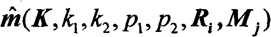
本发明与现有技术方法相比,图像幅数大为减少,图像质量高,标定图案无需占满整个屏幕;把标定表显示在液晶显示器屏幕上进行标定,LCD机身小巧,便于携带;价格便宜;几何变形趋近完美,保真性能好;编程绘制各种图案并显示在液晶显示器屏幕上,简单方便,并能达到高的标定精度等优点。Compared with the method in the prior art, the present invention greatly reduces the number of images, has high image quality, and the calibration pattern does not need to occupy the entire screen; the calibration table is displayed on the liquid crystal display screen for calibration, and the LCD body is compact and easy to carry; the price Inexpensive; the geometric deformation is close to perfection, and the fidelity performance is good; programming draws various patterns and displays them on the LCD screen, which is simple and convenient, and can achieve high calibration accuracy and other advantages.
附图说明: Description of drawings:
图1为本发明设计使用的标定表。Fig. 1 is the calibration table designed and used by the present invention.
图2为本发明涉及的理想二阶模型。Fig. 2 is an ideal second-order model involved in the present invention.
具体实施方式: Detailed ways:
下面通过实施例并结合附图对本发明做进一步的说明。The present invention will be further described below through the embodiments and in conjunction with the accompanying drawings.
实施例1:Example 1:
本实施例的具体过程和步骤包括:The specific process and steps of this embodiment include:
1.绘制标定表并拍摄图像1. Draw a calibration table and take an image
本实施例所用标定表如图1所示,在其上分布N行M列易于识别的特征圆点,其中5个特征圆点的直径明显大于其它特征圆点的直径,不对称分布的5个大圆点所处的位置能够区分它们各自的身份;另外,这5个大圆还用于标定表坐标轴的确定和其它各圆点的定位与身份识别;取标定表左上角特征点的圆心为原点,以标定表较长的一条边为x轴,向右为正;以较短的一条边为y轴,向下为正;以数码相机绕光轴旋转拍摄的方式对标定表拍摄几幅图像,拍摄过程中焦距保持不变。The calibration table used in this embodiment is shown in Figure 1, on which N rows and M columns of easily identifiable feature dots are distributed, wherein the diameters of 5 feature dots are obviously larger than the diameters of other feature dots, and the 5 asymmetrically distributed The positions of the big dots can distinguish their respective identities; in addition, these five big circles are also used to determine the coordinate axis of the calibration table and the positioning and identification of other dots; take the center of the feature point in the upper left corner of the calibration table as The origin, take the longer side of the calibration table as the x-axis, positive to the right; take the shorter side as the y-axis, and positive downward; take a few pictures of the calibration table by rotating the digital camera around the optical axis image, the focal length remains constant during capture.
2.特征圆点圆心的亚像素图像坐标获取2. Acquisition of sub-pixel image coordinates of the center of the feature circle
首先把拍摄得到的彩色图像转化为灰度图像;再采用高斯滤波对图像进行平滑处理,从而抑制噪声,改善图像质量;然后应用Canny边缘检测算子,提取图像中像素级的轮廓,再用Fourier-Mellin矩算子寻找亚像素级边缘,利用亚像素级的轮廓边缘进行椭圆拟合可以提高椭圆中心定位精度;最后采用最小二乘椭圆拟合方法提取图像中所有的椭圆目标,设定阈值检测出需要的椭圆目标,其中5个大圆成像后得到的椭圆的周长明显大于其它圆成像后得到的椭圆的周长。拟合得到的椭圆中心的坐标,即为标定表上特征圆中心的图像坐标。First, the color image obtained by shooting is converted into a grayscale image; then Gaussian filter is used to smooth the image to suppress noise and improve image quality; then apply the Canny edge detection operator to extract the pixel-level contour in the image, and then use Fourier -Mellin moment operator to find sub-pixel-level edges, using sub-pixel-level contour edges for ellipse fitting can improve the positioning accuracy of ellipse centers; finally, the least squares ellipse fitting method is used to extract all ellipse targets in the image, and threshold detection is set The required ellipse target can be obtained, and the perimeter of the ellipse obtained after imaging the five great circles is obviously larger than the perimeter of the ellipse obtained after imaging other circles. The coordinates of the center of the ellipse obtained by fitting are the image coordinates of the center of the feature circle on the calibration table.
基于正交Fourier-Mellin矩的亚像素边缘检测算法如下:The sub-pixel edge detection algorithm based on orthogonal Fourier-Mellin moments is as follows:
图像f(x,y)的OFMM的p阶q次表达式为:The p-order q-th expression of the OFMM of the image f(x, y) is:
其中f(x,y)表示图像在像素(x,y)时的灰度值,
把单位圆内图像逆时针旋转ψ角度的变换公式为:The transformation formula for rotating the image in the unit circle counterclockwise by the angle ψ is:
O′pq=Opqe-iqψ (4)O′ pq =O pq e -iqψ (4)
用三个基本参数(l,k,h)代表理想灰度阶跃模型,如图2所示。其中l表示从中心点到边缘的距离,h表示背景灰度值,k表示背景与边缘的阶跃值。ψ是x轴与垂直于边缘的线段的角度(即当图像逆时针旋转ψ角度后,x轴垂直与所求边缘)。三个基本参数是通过对图像上每个点的OFMM运算,即用核函数对图像加权并在单位圆上进行积分而得到。The ideal gray-scale step model is represented by three basic parameters (l, k, h), as shown in Figure 2. Where l represents the distance from the center point to the edge, h represents the gray value of the background, and k represents the step value between the background and the edge. ψ is the angle between the x-axis and the line segment perpendicular to the edge (that is, when the image is rotated counterclockwise by ψ angle, the x-axis is perpendicular to the desired edge). The three basic parameters are obtained by performing OFMM operations on each point on the image, that is, weighting the image with a kernel function and integrating it on the unit circle.
旋转后根据积分定义可知:According to the integral definition after rotation, we know:
其中f′(x,y)表示旋转后的边缘。旋转角度的计算公式为:where f'(x, y) represents the rotated edge. The formula for calculating the rotation angle is:
由旋转后不同阶次的OFMM矩可以推导出图2的各个参数:The parameters in Figure 2 can be derived from the OFMM moments of different orders after rotation:
从而计算出边缘的精确位置:The exact position of the edge is thus calculated:
其中,(x,y)表示图2的圆心坐标,(xs,ys)为图像的亚像素坐标。在使用模板与图像进行卷积时,得到的矩参数是图像N×N个像素区域内的矩参数,因此在计算精确位置时,还应该在l的基础上减小N/2。Among them, (x, y) represents the coordinates of the center of the circle in Figure 2, and (x s , y s ) is the sub-pixel coordinates of the image. When using the template to convolve with the image, the obtained moment parameter is the moment parameter in the N×N pixel area of the image, so when calculating the precise position, it should also be reduced by N/2 on the basis of l.
由于矩方法是对图像上的每个点都要在模板范围内进行卷积,所以运算量较大,为此在进行OFMM方法进行边缘检测时,首先使用Canny算法对边缘进行初始定位,然后采用计算出OFMM各阶次的7×7模板对图像进行卷积运算。这样不但可以提高运行效率而且可以达到精确定位的目的。Since the moment method is to convolve each point on the image within the scope of the template, the amount of calculation is relatively large. Therefore, when performing edge detection with the OFMM method, the Canny algorithm is first used to initially position the edge, and then the Calculate the 7×7 templates of each order of OFMM to perform convolution operation on the image. This can not only improve the operating efficiency but also achieve the purpose of precise positioning.
3.图像点与空间点对应3. Correspondence between image points and space points
本实施例采用的图像点与空间点的对应法,只要识别出5个大圆的圆点坐标,就可以利用5个大圆的定位作用自动建立图像中其它被识别出的图像点与其空间点坐标之间的对应;即使在某些点不可见或没有被提取的情况下,仍能建立其图像点与空间点的对应,算法有足够的鲁棒性;算法步骤如下:The correspondence method between the image point and the space point adopted in this embodiment, as long as the circle point coordinates of 5 great circles are identified, the positioning function of the 5 great circles can be used to automatically establish the relationship between other recognized image points and their space point coordinates in the image. Correspondence between points; even when some points are invisible or not extracted, the correspondence between image points and space points can still be established, and the algorithm is robust enough; the algorithm steps are as follows:
(1)首先判断5个大圆是否全部被提取出,如果全部提取,则继续到第2步;否则,图像不符合要求,结束算法;(1) First judge whether all 5 large circles have been extracted, if all are extracted, continue to step 2; otherwise, the image does not meet the requirements, and the algorithm ends;
(2)5个大圆的识别,计算图像上两两大圆中心之间的距离,距离最小的1号和2号圆分为第一组;利用1号和2号连线与3号和4号连线平行,把3号和4号两圆分为第二组;剩下的一个即为5号大圆;另外,计算1号和2号两圆分别到3号和4号两圆的距离差,离3号和4号距离差的绝对值较大的为1号,另一个为2号;然后,计算3号和4号到1号圆的距离,距离较小的为3号,距离较大的为4号;至此,五个大圆被全部识别;(2) Recognition of 5 great circles, calculate the distance between the centers of the two big circles on the image, and the circles No. 1 and No. 2 with the smallest distance are divided into the first group; use the connection line No. 1 and No. 2 to connect No. 3 and No. 4 The connecting lines are parallel, divide the two circles No. 3 and No. 4 into the second group; the remaining one is the No. 5 great circle; in addition, calculate the distance difference between No. 1 and No. 2 circles and No. 3 and No. 4 circles respectively , the one with the larger absolute value of the distance difference between No. 3 and No. 4 is No. 1, and the other is No. 2; then, calculate the distance from No. 3 and No. 4 to No. 1 circle, and the one with the smaller distance is No. 3. The big one is number 4; so far, all five big circles have been identified;
(3)根据求出的5个大圆确定中心点像素坐标,并根据圆心点间的距离从中心点开始逐层向外,计算其它特征点的坐标;(3) Determine the pixel coordinates of the center point according to the five large circles obtained, and calculate the coordinates of other feature points from the center point to the outside layer by layer according to the distance between the center points;
(4)比较识别出的图像坐标和计算出的图像坐标,从而确定图像点和空间点的对应。(4) Compare the recognized image coordinates with the calculated image coordinates, so as to determine the correspondence between image points and spatial points.
4.不考虑镜头畸变时相机参数计算4. Calculation of camera parameters without considering lens distortion
三维空间点X在相机成像平面上的投影用理想针孔模型描述齐次坐标表示为:The projection of the three-dimensional space point X on the camera imaging plane is described by the ideal pinhole model. The homogeneous coordinates are expressed as:
式中:s为一个比例系数;[xw yw zw]T为X在世界坐标系下的坐标;[u v]T为X在图像平面上的像点坐标;R和t分别为从世界坐标系到相机坐标系的旋转变换矩阵和平移变换向量;K为相机内参数矩阵;(u0,v0)为图像平面的主点坐标;α,β分别为图像在u轴和v轴的焦距参数;γ为图像扭曲参数,表示图像两坐标轴偏斜度。In the formula: s is a proportional coefficient; [x w y w z w ] T is the coordinate of X in the world coordinate system; [u v] T is the pixel coordinate of X on the image plane; R and t are respectively from the world The rotation transformation matrix and translation transformation vector from the coordinate system to the camera coordinate system; K is the camera internal parameter matrix; (u 0 , v 0 ) is the principal point coordinates of the image plane; α, β are the coordinates of the image on the u axis and v axis The focal length parameter; γ is the image distortion parameter, indicating the skewness of the two coordinate axes of the image.
本实施例所用的标定表是平面的,所以标定表上的圆心点的世界坐xi=[xi yi 0]T,即z分量为0,本方法中采用绕光轴旋转拍摄图像的方式,不存在相机的平移,由(9)式可得The calibration table used in this embodiment is planar, so the world coordinates x i =[ xi y i 0] T of the center point on the calibration table, that is, the z component is 0, and in this method, the rotation around the optical axis is used to capture the image way, there is no camera translation, from (9) can get
式中:r1,r2,r3分别为旋转矩阵R的3个列向量,式(10)可以写成In the formula: r 1 , r 2 , r 3 are the three column vectors of the rotation matrix R respectively, and formula (10) can be written as
式中:
矩阵H根据图像点与空间点的对应,利用非线性最小化方法进行求解,令H=[h1 h2 h3],可以得到According to the correspondence between image points and space points, the matrix H is solved by nonlinear minimization method, let H=[h 1 h 2 h 3 ], we can get
[h1 h2 h3]=K[r1 r2 0] (12)[h 1 h 2 h 3 ]=K[r 1 r 2 0] (12)
根据旋转矩阵列向量r1,r2的单位正交性,可以得到以下约束方程According to the unit orthogonality of the column vector r 1 and r 2 of the rotation matrix, the following constraint equation can be obtained
根据设计的标定表,每次拍摄的图像能够建立足够的图像点与空间点的对应,从而可以求出矩阵H,进一步得到2个线性约束方程,而矩阵K中有5个未知量需要标定,那么如果有n幅图像,就可以得到2n个线性方程;当n≥3时,就可以根据式(13)求解出K中的5个未知量;然后根据式(12)可以进一步求出每次拍摄时相机相对于世界坐标系的外部参数According to the designed calibration table, enough correspondence between image points and space points can be established for each image taken, so that the matrix H can be obtained, and two linear constraint equations can be further obtained, and there are 5 unknown quantities in the matrix K that need to be calibrated. Then if there are n images, 2n linear equations can be obtained; when n≥3, the 5 unknowns in K can be solved according to formula (13); then according to formula (12), each External parameters of the camera relative to the world coordinate system when shooting
式中:λ=1/||K-1h1||=1/||K-1h2||;至此,得到了所有的内外参数。In the formula: λ=1/||K -1 h 1 ||=1/||K -1 h 2 ||; so far, all internal and external parameters have been obtained.
5.考虑镜头畸变时相机参数计算和参数优化5. Camera parameter calculation and parameter optimization when lens distortion is considered
由于实际的成像过程是一个复杂的光学过程,实际的镜头并不是理想的,带有不同程度的畸变,所以理想针孔模型不能准确地描述成像几何关系;为了使模型更客观地反映相机的成像过程,引入了反映畸变影响的修正系数;描述非线性畸变可用如下公式:Since the actual imaging process is a complex optical process, the actual lens is not ideal, with varying degrees of distortion, so the ideal pinhole model cannot accurately describe the imaging geometric relationship; in order to make the model more objectively reflect the imaging of the camera In the process, a correction coefficient reflecting the influence of distortion is introduced; the following formula can be used to describe nonlinear distortion:
其中,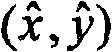
δx(x,y)=x[k1r2+k2r4]+[2p1xy+p2(r2+2x2)]δ x (x, y) = x[k 1 r 2 +k 2 r 4 ]+[2p 1 xy+p 2 (r 2 +2x 2 )]
(16)(16)
δy(x,y)=y[k1r2+k2r4]+[p1(r2+2y2)+2p2xy]δ y (x, y)=y[k 1 r 2 +k 2 r 4 ]+[p 1 (r 2 +2y 2 )+2p 2 xy]
其中
利用最大似然估计的方法对内外参数求精,给出标定表的n幅图像,每幅图像上m个圆点,优化模型为:Use the method of maximum likelihood estimation to refine the internal and external parameters, give n images of the calibration table, and m dots on each image, the optimization model is:
最大似然估计通过最小化式(2)获得,这是一个非线性最小化问题,通过Levenberg-Marquardt算法进行求解。The maximum likelihood estimation is obtained by minimizing formula (2), which is a nonlinear minimization problem, and is solved by the Levenberg-Marquardt algorithm.
实施例2:Example 2:
该实施例采用分辨率为4256×2848的FinePix S5Pro数码相机;焦距为24mm的AF Nikkor光学镜头;华硕X81H32SE-SL笔记本电脑,液晶显示器屏幕尺寸为14.1英寸,分辨率1280×800,点距为0.2375mm;标定程序以VC++6.0和OpenCV为编写工具,在WindowsXP系统上运行;设计的标定表如图1,小圆直径4.75mm,大圆直径9.50mm,圆心间隔20.425mm。This embodiment adopts the FinePix S5Pro digital camera that the resolution is 4256 * 2848; The focal length is the AF Nikkor optical lens of 24mm; ASUS X81H32SE-SL notebook computer, the liquid crystal display screen size is 14.1 inches, and the resolution is 1280 * 800, and the dot pitch is 0.2375 mm; the calibration program is written with VC++6.0 and OpenCV, and runs on the WindowsXP system; the designed calibration table is shown in Figure 1, the diameter of the small circle is 4.75mm, the diameter of the large circle is 9.50mm, and the distance between the centers of the circles is 20.425mm.
首先将标定表显示在液晶显示器LCD上,用数码相机绕光轴对LCD(光轴垂直于LCD屏幕)中的标定表旋转拍摄4幅图像,利用拍摄得到的图像进行标定实验。得到的标定结果为:First, the calibration table is displayed on the liquid crystal display LCD, and a digital camera is used to rotate the calibration table in the LCD (the optical axis is perpendicular to the LCD screen) around the optical axis to capture 4 images, and use the captured images to perform calibration experiments. The calibration result obtained is:
k1=-0.11068985 k2=0.23840439k 1 =-0.11068985 k 2 =0.23840439
p1=-3.93080791×10⁻⁴ p2=7.30140317×10⁻⁴ p 1 =-3.93080791×10 -4 p 2 =7.30140317×10 -4
为了检验实验结果的准确性,计算三维空间点的重投影误差:利用标定得到的参数,对标定表上的三维空间点做投影变换,从而得到在该参数条件下标定表特征圆点的像素坐标


表1四幅图像的重投影误差(单位:像素)Table 1 Reprojection errors of the four images (unit: pixel)

另外,对标定表绕光轴旋转拍摄3幅图像,对拍摄得到的图像进行实验,得到的标定结果及重投影误差分别如下:In addition, the calibration table is rotated around the optical axis to shoot 3 images, and experiments are carried out on the captured images. The calibration results and reprojection errors obtained are as follows:
k1=-0.11095357 k2=0.26004455k 1 =-0.11095357 k 2 =0.26004455
p1=-4.14503813×10⁻⁴ p2=6.56706343×10⁻⁴ p 1 =-4.14503813×10 -4 p 2 =6.56706343×10 -4
表2三幅图像的重投影误差(单位:像素)Table 2 Reprojection errors of the three images (unit: pixel)

从上述表格可以看出重投影平均误差在0.04个像素附近波动,当图像幅数较少时,也能实现高精度标定。在相机参数确定以后,可以利用光学三角形原理计算出空间点的三维坐标,利用本实施例标定得到的参数,对间距精确值为60mm的两个点的三维坐标进行反求,100次测量实验得到的这两个点间的平均距离为60.01745mm,相对误差均值为0.02908%。重投影误差分析及三维空间点的反求结果与实际数据的比较,验证了本发明方法的可行性及高的标定精度。It can be seen from the above table that the average error of reprojection fluctuates around 0.04 pixels, and high-precision calibration can also be achieved when the number of images is small. After the camera parameters are determined, the three-dimensional coordinates of the spatial point can be calculated by using the principle of optical triangles, and the parameters obtained by calibration in this embodiment are used to reverse the three-dimensional coordinates of two points with an accurate distance of 60mm, and 100 times of measurement experiments are obtained The average distance between these two points is 60.01745mm, and the average relative error is 0.02908%. The re-projection error analysis and the comparison of the inverse results of the three-dimensional space points with the actual data verify the feasibility and high calibration accuracy of the method of the present invention.
Claims (3)
Priority Applications (1)
| Application Number | Priority Date | Filing Date | Title |
|---|---|---|---|
| CN2009100195282A CN101673397B (en) | 2009-09-30 | 2009-09-30 | Digital camera nonlinear calibration method based on LCDs |
Applications Claiming Priority (1)
| Application Number | Priority Date | Filing Date | Title |
|---|---|---|---|
| CN2009100195282A CN101673397B (en) | 2009-09-30 | 2009-09-30 | Digital camera nonlinear calibration method based on LCDs |
Publications (2)
| Publication Number | Publication Date |
|---|---|
| CN101673397A true CN101673397A (en) | 2010-03-17 |
| CN101673397B CN101673397B (en) | 2012-04-25 |
Family
ID=42020610
Family Applications (1)
| Application Number | Title | Priority Date | Filing Date |
|---|---|---|---|
| CN2009100195282A Expired - Fee Related CN101673397B (en) | 2009-09-30 | 2009-09-30 | Digital camera nonlinear calibration method based on LCDs |
Country Status (1)
| Country | Link |
|---|---|
| CN (1) | CN101673397B (en) |
Cited By (27)
| Publication number | Priority date | Publication date | Assignee | Title |
|---|---|---|---|---|
| CN103034845A (en) * | 2012-12-11 | 2013-04-10 | 北京理工大学 | Symmetrical edge submicron precision feature identification method of miniature part to be assembled |
| CN103048872A (en) * | 2013-01-19 | 2013-04-17 | 杭州图方科技有限公司 | Full-automatic numerical control camera calibration system |
| CN104574388A (en) * | 2014-12-29 | 2015-04-29 | 东莞市神州视觉科技有限公司 | Camera calibration system and 3D (three-dimensional) calibration method thereof |
| CN105654484A (en) * | 2015-12-30 | 2016-06-08 | 西北工业大学 | Light field camera external parameter calibration device and method |
| CN105701776A (en) * | 2016-01-07 | 2016-06-22 | 武汉精测电子技术股份有限公司 | Lens distortion correcting method and system used for automatic optical detection |
| CN106596063A (en) * | 2014-06-27 | 2017-04-26 | 歌尔科技有限公司 | Method for measuring lens distortion and system thereof |
| CN106803261A (en) * | 2015-11-20 | 2017-06-06 | 沈阳新松机器人自动化股份有限公司 | robot relative pose estimation method |
| CN107204017A (en) * | 2017-06-08 | 2017-09-26 | 爱佩仪中测(成都)精密仪器有限公司 | A kind of single camera scaling method in three-dimensional measurement |
| CN107633536A (en) * | 2017-08-09 | 2018-01-26 | 武汉科技大学 | A kind of camera calibration method and system based on two-dimensional planar template |
| CN108171757A (en) * | 2017-12-28 | 2018-06-15 | 华勤通讯技术有限公司 | Camera calibration system and method |
| CN108881898A (en) * | 2018-06-07 | 2018-11-23 | 歌尔股份有限公司 | The test method of depth of field mould group nonlinear calibration |
| CN108917595A (en) * | 2018-06-19 | 2018-11-30 | 杭州蓝蜓科技有限公司 | Glass on-line measuring device based on machine vision |
| CN109189213A (en) * | 2018-08-15 | 2019-01-11 | 华中科技大学 | A kind of assembling process of products augmented reality guidance method based on movable computer |
| US10192325B2 (en) | 2015-07-31 | 2019-01-29 | SZ DJI Technology Co., Ltd. | Method for calibrating an imaging device and an imaging device |
| CN109360249A (en) * | 2018-12-06 | 2019-02-19 | 北京工业大学 | Camera Adjustable Calibration System |
| CN110148174A (en) * | 2019-05-23 | 2019-08-20 | 北京阿丘机器人科技有限公司 | Scaling board, scaling board recognition methods and device |
| CN110595387A (en) * | 2019-08-01 | 2019-12-20 | 佛山市南海区广工大数控装备协同创新研究院 | A calibration method for 3D reconstruction system based on multi-frequency structured light |
| WO2020107196A1 (en) * | 2018-11-27 | 2020-06-04 | 深圳市大疆创新科技有限公司 | Photographing quality evaluation method and apparatus for photographing apparatus, and terminal device |
| CN111311682A (en) * | 2020-02-24 | 2020-06-19 | 卡莱特(深圳)云科技有限公司 | Pose estimation method and device in LED screen correction process and electronic equipment |
| CN111398625A (en) * | 2020-03-19 | 2020-07-10 | 西安理工大学 | Speed measuring method in physical model test |
| CN112432594A (en) * | 2020-10-22 | 2021-03-02 | 中国计量科学研究院 | Machine vision six-degree-of-freedom measurement method based on physical decoupling |
| CN113450398A (en) * | 2021-08-31 | 2021-09-28 | 北京柏惠维康科技有限公司 | Method, device, equipment and readable medium for matching marker in calibration object |
| CN116379928A (en) * | 2022-12-30 | 2023-07-04 | 珠海华冠科技股份有限公司 | A calibration board and its application |
| CN116977449A (en) * | 2023-09-25 | 2023-10-31 | 安徽大学 | An active calibration method for compound eye event cameras based on flickering checkerboard |
| CN117541662A (en) * | 2024-01-10 | 2024-02-09 | 中国科学院长春光学精密机械与物理研究所 | Method for calibrating camera internal parameters and deriving camera coordinate system simultaneously |
| CN118334162A (en) * | 2024-06-12 | 2024-07-12 | 西南交通大学 | Calibration method of geometric parameters of X-ray tomography of plate-like components manufactured by laser additive manufacturing |
| CN119676464A (en) * | 2024-12-04 | 2025-03-21 | 北京邮电大学 | Non-periodic encoding method and related equipment for suppressing three-dimensional display distortion |
Families Citing this family (1)
| Publication number | Priority date | Publication date | Assignee | Title |
|---|---|---|---|---|
| CN110232716A (en) * | 2019-05-31 | 2019-09-13 | 深圳市道通智能航空技术有限公司 | A kind of camera calibration method, apparatus and electronic equipment |
Family Cites Families (3)
| Publication number | Priority date | Publication date | Assignee | Title |
|---|---|---|---|---|
| CN1198112C (en) * | 2002-01-31 | 2005-04-20 | 明基电通股份有限公司 | Coordinate positioning method for screen measurement |
| JP4147059B2 (en) * | 2002-07-03 | 2008-09-10 | 株式会社トプコン | Calibration data measuring device, measuring method and measuring program, computer-readable recording medium, and image data processing device |
| JP4307934B2 (en) * | 2003-08-13 | 2009-08-05 | 株式会社トプコン | Imaging apparatus and method with image correction function, and imaging apparatus and method |
-
2009
- 2009-09-30 CN CN2009100195282A patent/CN101673397B/en not_active Expired - Fee Related
Cited By (40)
| Publication number | Priority date | Publication date | Assignee | Title |
|---|---|---|---|---|
| CN103034845B (en) * | 2012-12-11 | 2018-06-05 | 北京理工大学 | Towards the symmetrical edge sub-micrometer precision characteristic recognition method of micro- part of assembling |
| CN103034845A (en) * | 2012-12-11 | 2013-04-10 | 北京理工大学 | Symmetrical edge submicron precision feature identification method of miniature part to be assembled |
| CN103048872A (en) * | 2013-01-19 | 2013-04-17 | 杭州图方科技有限公司 | Full-automatic numerical control camera calibration system |
| CN103048872B (en) * | 2013-01-19 | 2015-07-08 | 吴军 | Full-automatic numerical control camera calibration system |
| CN106596063A (en) * | 2014-06-27 | 2017-04-26 | 歌尔科技有限公司 | Method for measuring lens distortion and system thereof |
| CN106596063B (en) * | 2014-06-27 | 2019-05-24 | 歌尔科技有限公司 | A kind of method and system measuring lens distortion |
| CN104574388B (en) * | 2014-12-29 | 2017-08-29 | 东莞市神州视觉科技有限公司 | A kind of camera calibration system and its 3D scaling methods |
| CN104574388A (en) * | 2014-12-29 | 2015-04-29 | 东莞市神州视觉科技有限公司 | Camera calibration system and 3D (three-dimensional) calibration method thereof |
| US10546390B2 (en) | 2015-07-31 | 2020-01-28 | SZ DJI Technology Co., Ltd. | Method for calibrating an imaging device and an imaging device |
| US10192325B2 (en) | 2015-07-31 | 2019-01-29 | SZ DJI Technology Co., Ltd. | Method for calibrating an imaging device and an imaging device |
| CN106803261A (en) * | 2015-11-20 | 2017-06-06 | 沈阳新松机器人自动化股份有限公司 | robot relative pose estimation method |
| CN105654484B (en) * | 2015-12-30 | 2019-01-18 | 西北工业大学 | Light-field camera external parameters calibration device and method |
| CN105654484A (en) * | 2015-12-30 | 2016-06-08 | 西北工业大学 | Light field camera external parameter calibration device and method |
| CN105701776A (en) * | 2016-01-07 | 2016-06-22 | 武汉精测电子技术股份有限公司 | Lens distortion correcting method and system used for automatic optical detection |
| CN107204017A (en) * | 2017-06-08 | 2017-09-26 | 爱佩仪中测(成都)精密仪器有限公司 | A kind of single camera scaling method in three-dimensional measurement |
| CN107633536A (en) * | 2017-08-09 | 2018-01-26 | 武汉科技大学 | A kind of camera calibration method and system based on two-dimensional planar template |
| CN108171757A (en) * | 2017-12-28 | 2018-06-15 | 华勤通讯技术有限公司 | Camera calibration system and method |
| CN108881898A (en) * | 2018-06-07 | 2018-11-23 | 歌尔股份有限公司 | The test method of depth of field mould group nonlinear calibration |
| CN108917595A (en) * | 2018-06-19 | 2018-11-30 | 杭州蓝蜓科技有限公司 | Glass on-line measuring device based on machine vision |
| CN109189213A (en) * | 2018-08-15 | 2019-01-11 | 华中科技大学 | A kind of assembling process of products augmented reality guidance method based on movable computer |
| WO2020107196A1 (en) * | 2018-11-27 | 2020-06-04 | 深圳市大疆创新科技有限公司 | Photographing quality evaluation method and apparatus for photographing apparatus, and terminal device |
| CN109360249A (en) * | 2018-12-06 | 2019-02-19 | 北京工业大学 | Camera Adjustable Calibration System |
| CN110148174A (en) * | 2019-05-23 | 2019-08-20 | 北京阿丘机器人科技有限公司 | Scaling board, scaling board recognition methods and device |
| CN110595387A (en) * | 2019-08-01 | 2019-12-20 | 佛山市南海区广工大数控装备协同创新研究院 | A calibration method for 3D reconstruction system based on multi-frequency structured light |
| CN110595387B (en) * | 2019-08-01 | 2022-05-13 | 佛山市南海区广工大数控装备协同创新研究院 | Calibration method of three-dimensional reconstruction system based on multi-frequency structured light |
| CN111311682A (en) * | 2020-02-24 | 2020-06-19 | 卡莱特(深圳)云科技有限公司 | Pose estimation method and device in LED screen correction process and electronic equipment |
| CN111398625A (en) * | 2020-03-19 | 2020-07-10 | 西安理工大学 | Speed measuring method in physical model test |
| CN111398625B (en) * | 2020-03-19 | 2022-04-12 | 西安理工大学 | A Velocity Measurement Method in Physical Model Test |
| CN112432594A (en) * | 2020-10-22 | 2021-03-02 | 中国计量科学研究院 | Machine vision six-degree-of-freedom measurement method based on physical decoupling |
| CN113450398A (en) * | 2021-08-31 | 2021-09-28 | 北京柏惠维康科技有限公司 | Method, device, equipment and readable medium for matching marker in calibration object |
| CN113450398B (en) * | 2021-08-31 | 2021-11-19 | 北京柏惠维康科技有限公司 | Method, device, equipment and readable medium for matching marker in calibration object |
| CN116379928A (en) * | 2022-12-30 | 2023-07-04 | 珠海华冠科技股份有限公司 | A calibration board and its application |
| CN116977449A (en) * | 2023-09-25 | 2023-10-31 | 安徽大学 | An active calibration method for compound eye event cameras based on flickering checkerboard |
| CN116977449B (en) * | 2023-09-25 | 2024-03-15 | 安徽大学 | An active calibration method for compound eye event cameras based on flickering checkerboard |
| CN117541662A (en) * | 2024-01-10 | 2024-02-09 | 中国科学院长春光学精密机械与物理研究所 | Method for calibrating camera internal parameters and deriving camera coordinate system simultaneously |
| CN117541662B (en) * | 2024-01-10 | 2024-04-09 | 中国科学院长春光学精密机械与物理研究所 | A method for simultaneously calibrating camera intrinsic parameters and deriving camera coordinate system |
| CN118334162A (en) * | 2024-06-12 | 2024-07-12 | 西南交通大学 | Calibration method of geometric parameters of X-ray tomography of plate-like components manufactured by laser additive manufacturing |
| CN118334162B (en) * | 2024-06-12 | 2024-08-06 | 西南交通大学 | Method for calibrating geometrical parameters of X-ray tomography of plate-shaped component manufactured by laser additive |
| CN119676464A (en) * | 2024-12-04 | 2025-03-21 | 北京邮电大学 | Non-periodic encoding method and related equipment for suppressing three-dimensional display distortion |
| CN119676464B (en) * | 2024-12-04 | 2025-11-07 | 北京邮电大学 | Aperiodic coding method for inhibiting three-dimensional display distortion and related equipment |
Also Published As
| Publication number | Publication date |
|---|---|
| CN101673397B (en) | 2012-04-25 |
Similar Documents
| Publication | Publication Date | Title |
|---|---|---|
| CN101673397B (en) | Digital camera nonlinear calibration method based on LCDs | |
| CN111260731B (en) | Self-adaptive detection method for checkerboard sub-pixel level corner points | |
| CN113012234B (en) | High-precision camera calibration method based on plane transformation | |
| CN105096317B (en) | A kind of high-performance camera full automatic calibration method in complex background | |
| CN107507235B (en) | Registration method of color image and depth image acquired based on RGB-D equipment | |
| CN101697233B (en) | Structured light-based three-dimensional object surface reconstruction method | |
| CN105931222B (en) | The method for realizing high-precision camera calibration with low precision two dimensional surface target | |
| CN106887023A (en) | For scaling board and its scaling method and calibration system that binocular camera is demarcated | |
| CN112132907A (en) | A camera calibration method, device, electronic device and storage medium | |
| CN114998448B (en) | A method for multi-constrained binocular fisheye camera calibration and spatial point positioning | |
| WO2024011764A1 (en) | Calibration parameter determination method and apparatus, hybrid calibration board, device, and medium | |
| CN114897864A (en) | Workpiece detection and defect judgment method based on digital and analog information | |
| CN103106661B (en) | Two, space intersecting straight lines linear solution parabolic catadioptric camera intrinsic parameter | |
| CN105389808A (en) | Camera self-calibration method based on two vanishing points | |
| CN102903101B (en) | Method for carrying out water-surface data acquisition and reconstruction by using multiple cameras | |
| CN102661708B (en) | High-density packaged element positioning method based on speeded up robust features (SURFs) | |
| CN103530880A (en) | Camera calibration method based on projected Gaussian grid pattern | |
| CN111968182A (en) | Calibration method for binocular camera nonlinear model parameters | |
| CN103400373A (en) | Method for automatically identifying and positioning coordinates of image point of artificial mark in camera calibration control field | |
| CN114963981B (en) | Cylindrical part butt joint non-contact measurement method based on monocular vision | |
| CN112419224A (en) | Spherical pin chip positioning method and system | |
| Cvišić et al. | Enhanced calibration of camera setups for high-performance visual odometry | |
| CN114998571A (en) | Image processing and color detection method based on fixed-size marker | |
| CN108876842A (en) | A kind of measurement method, system, equipment and the storage medium of sub-pixel edge angle | |
| CN107328371A (en) | Sub-pix contours extract based on Gaussian and the optimization using Softmax recurrence in the case where metal plate detects scene |
Legal Events
| Date | Code | Title | Description |
|---|---|---|---|
| C06 | Publication | ||
| PB01 | Publication | ||
| C10 | Entry into substantive examination | ||
| SE01 | Entry into force of request for substantive examination | ||
| C53 | Correction of patent for invention or patent application | ||
| CB02 | Change of applicant information |
Address after: 266061 Hongkong East Road, Laoshan District, Shandong, China, No. 7, No. Applicant after: Qingdao University Address before: 266071 Ningxia Road, Shandong, China, No. 308, No. Applicant before: Qingdao University |
|
| C14 | Grant of patent or utility model | ||
| GR01 | Patent grant | ||
| C17 | Cessation of patent right | ||
| CF01 | Termination of patent right due to non-payment of annual fee |
Granted publication date: 20120425 Termination date: 20120930 |