CN101641602A - Needle-septum interface for fluid analyzer - Google Patents
Needle-septum interface for fluid analyzer Download PDFInfo
- Publication number
- CN101641602A CN101641602A CN200680053377A CN200680053377A CN101641602A CN 101641602 A CN101641602 A CN 101641602A CN 200680053377 A CN200680053377 A CN 200680053377A CN 200680053377 A CN200680053377 A CN 200680053377A CN 101641602 A CN101641602 A CN 101641602A
- Authority
- CN
- China
- Prior art keywords
- needle
- fluid
- cartridge
- flow channel
- flow
- Prior art date
- Legal status (The legal status is an assumption and is not a legal conclusion. Google has not performed a legal analysis and makes no representation as to the accuracy of the status listed.)
- Granted
Links
Images


Classifications
-
- G—PHYSICS
- G01—MEASURING; TESTING
- G01N—INVESTIGATING OR ANALYSING MATERIALS BY DETERMINING THEIR CHEMICAL OR PHYSICAL PROPERTIES
- G01N35/00—Automatic analysis not limited to methods or materials provided for in any single one of groups G01N1/00 - G01N33/00; Handling materials therefor
- G01N35/10—Devices for transferring samples or any liquids to, in, or from, the analysis apparatus, e.g. suction devices, injection devices
- G01N35/1079—Devices for transferring samples or any liquids to, in, or from, the analysis apparatus, e.g. suction devices, injection devices with means for piercing stoppers or septums
-
- B—PERFORMING OPERATIONS; TRANSPORTING
- B01—PHYSICAL OR CHEMICAL PROCESSES OR APPARATUS IN GENERAL
- B01L—CHEMICAL OR PHYSICAL LABORATORY APPARATUS FOR GENERAL USE
- B01L3/00—Containers or dishes for laboratory use, e.g. laboratory glassware; Droppers
- B01L3/50—Containers for the purpose of retaining a material to be analysed, e.g. test tubes
- B01L3/502—Containers for the purpose of retaining a material to be analysed, e.g. test tubes with fluid transport, e.g. in multi-compartment structures
- B01L3/5027—Containers for the purpose of retaining a material to be analysed, e.g. test tubes with fluid transport, e.g. in multi-compartment structures by integrated microfluidic structures, i.e. dimensions of channels and chambers are such that surface tension forces are important, e.g. lab-on-a-chip
- B01L3/502715—Containers for the purpose of retaining a material to be analysed, e.g. test tubes with fluid transport, e.g. in multi-compartment structures by integrated microfluidic structures, i.e. dimensions of channels and chambers are such that surface tension forces are important, e.g. lab-on-a-chip characterised by interfacing components, e.g. fluidic, electrical, optical or mechanical interfaces
-
- B—PERFORMING OPERATIONS; TRANSPORTING
- B01—PHYSICAL OR CHEMICAL PROCESSES OR APPARATUS IN GENERAL
- B01L—CHEMICAL OR PHYSICAL LABORATORY APPARATUS FOR GENERAL USE
- B01L9/00—Supporting devices; Holding devices
- B01L9/52—Supports specially adapted for flat sample carriers, e.g. for plates, slides, chips
- B01L9/527—Supports specially adapted for flat sample carriers, e.g. for plates, slides, chips for microfluidic devices, e.g. used for lab-on-a-chip
-
- G—PHYSICS
- G01—MEASURING; TESTING
- G01N—INVESTIGATING OR ANALYSING MATERIALS BY DETERMINING THEIR CHEMICAL OR PHYSICAL PROPERTIES
- G01N35/00—Automatic analysis not limited to methods or materials provided for in any single one of groups G01N1/00 - G01N33/00; Handling materials therefor
- G01N35/10—Devices for transferring samples or any liquids to, in, or from, the analysis apparatus, e.g. suction devices, injection devices
- G01N35/1095—Devices for transferring samples or any liquids to, in, or from, the analysis apparatus, e.g. suction devices, injection devices for supplying the samples to flow-through analysers
-
- B—PERFORMING OPERATIONS; TRANSPORTING
- B01—PHYSICAL OR CHEMICAL PROCESSES OR APPARATUS IN GENERAL
- B01L—CHEMICAL OR PHYSICAL LABORATORY APPARATUS FOR GENERAL USE
- B01L2200/00—Solutions for specific problems relating to chemical or physical laboratory apparatus
- B01L2200/02—Adapting objects or devices to another
- B01L2200/026—Fluid interfacing between devices or objects, e.g. connectors, inlet details
- B01L2200/027—Fluid interfacing between devices or objects, e.g. connectors, inlet details for microfluidic devices
-
- B—PERFORMING OPERATIONS; TRANSPORTING
- B01—PHYSICAL OR CHEMICAL PROCESSES OR APPARATUS IN GENERAL
- B01L—CHEMICAL OR PHYSICAL LABORATORY APPARATUS FOR GENERAL USE
- B01L2200/00—Solutions for specific problems relating to chemical or physical laboratory apparatus
- B01L2200/14—Process control and prevention of errors
- B01L2200/143—Quality control, feedback systems
-
- B—PERFORMING OPERATIONS; TRANSPORTING
- B01—PHYSICAL OR CHEMICAL PROCESSES OR APPARATUS IN GENERAL
- B01L—CHEMICAL OR PHYSICAL LABORATORY APPARATUS FOR GENERAL USE
- B01L2300/00—Additional constructional details
- B01L2300/06—Auxiliary integrated devices, integrated components
- B01L2300/0627—Sensor or part of a sensor is integrated
-
- B—PERFORMING OPERATIONS; TRANSPORTING
- B01—PHYSICAL OR CHEMICAL PROCESSES OR APPARATUS IN GENERAL
- B01L—CHEMICAL OR PHYSICAL LABORATORY APPARATUS FOR GENERAL USE
- B01L2300/00—Additional constructional details
- B01L2300/06—Auxiliary integrated devices, integrated components
- B01L2300/0672—Integrated piercing tool
-
- B—PERFORMING OPERATIONS; TRANSPORTING
- B01—PHYSICAL OR CHEMICAL PROCESSES OR APPARATUS IN GENERAL
- B01L—CHEMICAL OR PHYSICAL LABORATORY APPARATUS FOR GENERAL USE
- B01L2300/00—Additional constructional details
- B01L2300/08—Geometry, shape and general structure
- B01L2300/0809—Geometry, shape and general structure rectangular shaped
- B01L2300/0816—Cards, e.g. flat sample carriers usually with flow in two horizontal directions
-
- B—PERFORMING OPERATIONS; TRANSPORTING
- B01—PHYSICAL OR CHEMICAL PROCESSES OR APPARATUS IN GENERAL
- B01L—CHEMICAL OR PHYSICAL LABORATORY APPARATUS FOR GENERAL USE
- B01L2400/00—Moving or stopping fluids
- B01L2400/04—Moving fluids with specific forces or mechanical means
- B01L2400/0475—Moving fluids with specific forces or mechanical means specific mechanical means and fluid pressure
- B01L2400/0481—Moving fluids with specific forces or mechanical means specific mechanical means and fluid pressure squeezing of channels or chambers
-
- B—PERFORMING OPERATIONS; TRANSPORTING
- B01—PHYSICAL OR CHEMICAL PROCESSES OR APPARATUS IN GENERAL
- B01L—CHEMICAL OR PHYSICAL LABORATORY APPARATUS FOR GENERAL USE
- B01L2400/00—Moving or stopping fluids
- B01L2400/04—Moving fluids with specific forces or mechanical means
- B01L2400/0475—Moving fluids with specific forces or mechanical means specific mechanical means and fluid pressure
- B01L2400/0487—Moving fluids with specific forces or mechanical means specific mechanical means and fluid pressure fluid pressure, pneumatics
-
- B—PERFORMING OPERATIONS; TRANSPORTING
- B01—PHYSICAL OR CHEMICAL PROCESSES OR APPARATUS IN GENERAL
- B01L—CHEMICAL OR PHYSICAL LABORATORY APPARATUS FOR GENERAL USE
- B01L3/00—Containers or dishes for laboratory use, e.g. laboratory glassware; Droppers
- B01L3/50—Containers for the purpose of retaining a material to be analysed, e.g. test tubes
- B01L3/502—Containers for the purpose of retaining a material to be analysed, e.g. test tubes with fluid transport, e.g. in multi-compartment structures
- B01L3/5027—Containers for the purpose of retaining a material to be analysed, e.g. test tubes with fluid transport, e.g. in multi-compartment structures by integrated microfluidic structures, i.e. dimensions of channels and chambers are such that surface tension forces are important, e.g. lab-on-a-chip
- B01L3/502746—Containers for the purpose of retaining a material to be analysed, e.g. test tubes with fluid transport, e.g. in multi-compartment structures by integrated microfluidic structures, i.e. dimensions of channels and chambers are such that surface tension forces are important, e.g. lab-on-a-chip characterised by the means for controlling flow resistance, e.g. flow controllers, baffles
-
- G—PHYSICS
- G01—MEASURING; TESTING
- G01N—INVESTIGATING OR ANALYSING MATERIALS BY DETERMINING THEIR CHEMICAL OR PHYSICAL PROPERTIES
- G01N35/00—Automatic analysis not limited to methods or materials provided for in any single one of groups G01N1/00 - G01N33/00; Handling materials therefor
- G01N35/00029—Automatic analysis not limited to methods or materials provided for in any single one of groups G01N1/00 - G01N33/00; Handling materials therefor provided with flat sample substrates, e.g. slides
- G01N2035/00099—Characterised by type of test elements
- G01N2035/00158—Elements containing microarrays, i.e. "biochip"
Landscapes
- Chemical & Material Sciences (AREA)
- Health & Medical Sciences (AREA)
- Analytical Chemistry (AREA)
- General Health & Medical Sciences (AREA)
- Biochemistry (AREA)
- Chemical Kinetics & Catalysis (AREA)
- Physics & Mathematics (AREA)
- Life Sciences & Earth Sciences (AREA)
- Clinical Laboratory Science (AREA)
- Dispersion Chemistry (AREA)
- General Physics & Mathematics (AREA)
- Immunology (AREA)
- Pathology (AREA)
- Hematology (AREA)
- Automatic Analysis And Handling Materials Therefor (AREA)
- Infusion, Injection, And Reservoir Apparatuses (AREA)
Abstract
公开了用于流体分析仪的仪器-标本盒界面,该流体分析仪具有仪器和可拆卸的标本盒。在一个实施例中,该仪器包括针具,该针具适合于刺穿在可拆卸标本盒上的隔膜。还公开了用于检测可拆卸标本盒上的流通道中的流率的技术,以及用于检测可拆卸标本盒上的流通道中的流体的位置的技术。
An instrument-specimen cartridge interface for a fluid analyzer is disclosed. The fluid analyzer includes an instrument and a removable specimen cartridge. In one embodiment, the instrument includes a needle adapted to pierce a septum on the removable specimen cartridge. Also disclosed are techniques for detecting a flow rate in a flow channel on the removable specimen cartridge and techniques for detecting a position of a fluid in a flow channel on the removable specimen cartridge.
Description
领域field
本发明大致涉及流体分析仪,更具体地说,涉及具有仪器-标本盒(cartridge)界面(interface)的流体分析仪。The present invention relates generally to fluid analyzers and, more particularly, to fluid analyzers having an instrument-cartridge interface.
背景background
化学和/或生物分析对于生命科学研究、临床诊断和广泛范围的环境和过程监测是很重要的。在某些情况下,使用分析仪来执行和/或帮助执行样本流体的化学和/或生物分析。根据应用样本流体可以是液体或气体。Chemical and/or biological analysis is important for life science research, clinical diagnostics and monitoring of a wide range of environments and processes. In some cases, an analyzer is used to perform and/or assist in performing chemical and/or biological analysis of the sample fluid. Depending on the application the sample fluid can be a liquid or a gas.
某些分析仪包括容纳可拆卸的、在某些情况下是一次性的标本盒的仪器。在这种分析仪中,样本流体时常被引入或以其它方式提供给可拆卸的标本盒,并且该仪器通过一个或多个界面而与可拆卸的标本盒相互作用,以帮助执行和/或控制所需的化学和/或生物分析。根据应用,这些界面可包括,例如流体界面、电气界面和/或其它类型的界面。界面的完整性通常对于整个设备的功能是很重要的。例如,流体界面通常在可拆卸的标本盒和仪器之间输送一种或多种流体(液体或气体),且/或反之亦然,并且通常期望流体界面基本上是无泄漏的、可靠的且成本低廉的。Some analyzers include instruments that accommodate removable, and in some cases disposable, specimen cartridges. In such analyzers, sample fluid is often introduced or otherwise provided to a removable cartridge, and the instrument interacts with the removable cartridge through one or more interfaces to facilitate execution and/or control Chemical and/or biological analysis required. Depending on the application, these interfaces may include, for example, fluid interfaces, electrical interfaces, and/or other types of interfaces. The integrity of the interface is often important to the functionality of the overall device. For example, a fluid interface typically transports one or more fluids (liquid or gas) between the removable cartridge and the instrument, and/or vice versa, and it is often desirable that the fluid interface be substantially leak-free, reliable and Inexpensive.
概要summary
提供了本发明的以下概要以促进对本发明的某些独特的创新特征的理解,而不应被认为是全部描述。通过将整个说明书、权利要求、附图和摘要视为一个整体可获得对本发明的完整的理解。The following summary of the invention is provided to facilitate an understanding of some of the unique and innovative features of the invention and should not be considered a complete description. A full appreciation of the invention can be gained by taking the entire specification, claims, drawings, and abstract as a whole.
本发明大致涉及流体分析仪,更具体地说,涉及具有一个或多个仪器-标本盒界面的流体分析仪。在某些实施例中,该流体分析仪可以是流式血细胞球计数器和/或血液分析仪,其具有一个或多个位于仪器和一次性标本盒之间的无泄漏的界面,但也可以使用其它流体分析仪。The present invention relates generally to fluid analyzers, and more particularly to fluid analyzers having one or more instrument-cartridge interfaces. In some embodiments, the fluid analyzer may be a flow cytometer and/or hematology analyzer with one or more leak-free interfaces between the instrument and the disposable cartridge, but may also use Other fluid analyzers.
在一个说明性的实施例中,提供了流体分析仪,其包括标本盒和开口,标本盒具有由流通道壁限定的第一流通道,开口从标本盒的外面延伸到第一流通道中。隔膜布置在开口中或开口上,并用不透流体的密封而固定在标本盒的至少一部分上。还提供了用于容纳标本盒的仪器。第一针具可连接在该仪器上。第一针具尺寸可设置成装配在标本盒的第一流通道的开口中,并刺穿隔膜。在第一针具处于第一流通道的开口中,并穿过隔膜的情况下,仪器可在第一针具中引起流动,此流动又在标本盒的第一流通道中引起流动。在某些情况下,仪器可包括传感器等,以检测第一针具中所引起的流动。第一针具中所引起的流动可与标本盒的第一流通道中所引起的流动相关联。In one illustrative embodiment, a fluid analyzer is provided that includes a cartridge having a first flow channel defined by flow channel walls and an opening extending from an exterior of the cartridge into the first flow channel. A septum is disposed in or over the opening and secured to at least a portion of the cartridge with a fluid-tight seal. Also provided is an instrument for holding a specimen cassette. A first needle is connectable to the instrument. The first needle may be sized to fit within the opening of the first flow channel of the cartridge and pierce the septum. With the first needle in the opening of the first flow channel and passing through the septum, the instrument can induce flow in the first needle which in turn induces flow in the first flow channel of the cartridge. In some cases, the instrument may include a sensor or the like to detect the induced flow in the first needle. The induced flow in the first needle can be associated with the induced flow in the first flow channel of the cartridge.
当第一针具刺破并穿过隔膜时,隔膜可适合于在第一针具周围提供相对的不透流体的密封。备选或附加的是,隔膜可适合于在第一针具从隔膜抽出之后,重新密封开口。The septum may be adapted to provide a relatively fluid-tight seal around the first needle when the first needle pierces and passes through the septum. Alternatively or additionally, the septum may be adapted to reseal the opening after the first needle has been withdrawn from the septum.
在某些情况下,第一针具可包括主体、尖端和止动机构。止动机构可布置在第一针具主体的至少一部分周围,并离第一针具的尖端向后偏离一段距离。止动机构可偏离一段距离,该距离容许第一针具的尖端刺穿隔膜,但防止第一针具的尖端与标本盒的第一流通道的背面接合。In some cases, the first needle can include a body, a tip, and a stop mechanism. The stop mechanism may be disposed around at least a portion of the first needle body and offset a distance rearwardly from the tip of the first needle. The stop mechanism may be offset by a distance that allows the tip of the first needle to pierce the septum but prevents the tip of the first needle from engaging the back of the first flow channel of the cartridge.
在某些实施例中,标本盒包括第二流通道,并且仪器包括第二针具,该第二针具在标本盒的第二流通道和仪器之间输送流体。在某些情况下,第二针具通过仪器的流体路径而与第一针具流体连通。如果需要,仪器可包括用于检测仪器流体路径中的流体流动的流传感器。在其它情况下,第二针具可为标本盒提供独立受控的压力。在某些实施例中,根据需要,标本盒可包括第一针具和/或第二针具,并且仪器可包括一个或多个相应的隔膜。In some embodiments, the cartridge includes a second flow channel and the instrument includes a second needle that delivers fluid between the second flow channel of the cartridge and the instrument. In some cases, the second needle is in fluid communication with the first needle through the fluid path of the instrument. If desired, the instrument may include a flow sensor for detecting fluid flow in the instrument's fluid path. In other cases, the second needle can provide independently controlled pressure to the cartridge. In some embodiments, the cartridge may include a first needle and/or a second needle, and the instrument may include one or more corresponding septa, as desired.
在另一个说明性的实施例中,提供了流体分析仪,其包括标本盒和开口,标本盒具有由流通道壁限定的流通道,开口从标本盒的外面延伸到流通道中。弹性和/或柔性隔膜可布置在开口中或开口上,并通过不透流体的密封而固定在标本盒的至少一部分上。流体分析仪还可包括用于容纳标本盒的仪器。该仪器可具有柱塞,当仪器容纳标本盒时,柱塞与标本盒的弹性和/或柔性隔膜配准。仪器还可具有移动机构,其使柱塞的至少一端移动成与标本盒的弹性和/或柔性隔膜接合,从而使弹性和/或柔性隔膜变形,此变形改变了标本盒的流体室的体积,这又在标本盒的流通道中引起流动。In another illustrative embodiment, a fluid analyzer is provided that includes a cartridge having a flow channel defined by flow channel walls and an opening extending from an exterior of the cartridge into the flow channel. A resilient and/or flexible membrane may be disposed in or over the opening and secured to at least a portion of the cartridge by a fluid-tight seal. Fluid analyzers may also include instruments for receiving cartridges. The instrument may have a plunger that registers with the resilient and/or flexible membrane of the cartridge when the instrument receives the cartridge. The instrument may also have a movement mechanism that moves at least one end of the plunger into engagement with the elastic and/or flexible membrane of the cartridge, thereby deforming the elastic and/or flexible membrane, the deformation changing the volume of the fluid chamber of the cartridge, This in turn induces flow in the flow channel of the cartridge.
柱塞可以是任何类型的柱塞。例如,柱塞可包括刚性末端,并且仪器的移动机构可使柱塞的刚性末端朝着弹性和/或柔性隔膜移动,从而使弹性和/或柔性隔膜发生变形。柱塞可备选地包括可变形的弹性和/或柔性隔膜,并且仪器的移动机构可包括压力源,该压力源在柱塞末端的弹性和/或柔性隔膜的后面产生压力,从而使柱塞末端的弹性和/或柔性隔膜朝着标本盒的弹性和/或柔性隔膜发生变形。这又使标本盒的弹性和/或柔性隔膜变形,并且最终在标本盒的流通道中引起流动。The plunger can be of any type. For example, the plunger may include a rigid end, and the movement mechanism of the instrument may move the rigid end of the plunger toward the elastic and/or flexible membrane, thereby deforming the elastic and/or flexible membrane. The plunger may alternatively include a deformable elastic and/or flexible diaphragm, and the movement mechanism of the instrument may include a pressure source that generates pressure behind the elastic and/or flexible diaphragm at the end of the plunger, causing the plunger to The elastic and/or flexible membrane of the tip is deformed towards the elastic and/or flexible membrane of the cartridge. This in turn deforms the elastic and/or flexible membrane of the cartridge and ultimately induces flow in the flow channel of the cartridge.
在另一个说明性的实施例中,提供了流体分析仪,其包括标本盒,该标本盒具有第一主表面和相反的第二主表面,流通道定位在第一主表面和第二主表面之间。标本盒还可具有穿过第一主表面而延伸到第一流通道中的开口。这种流体标本盒还可具有用于容纳标本盒的仪器。仪器可具有压力源,该压力源至少有选择地与喷嘴成流体连通。压力源可以是任何类型的产生正压或负压的压力源。喷嘴定位在标本盒的开口上,并且当仪器容纳标本盒时,与该标本盒形成基本不透流体的密封。仪器可控制压力源的压力,从而通过喷嘴/开口的界面而在标本盒的流通道中引起所需的流动。在某些实施例中,标本盒可在开口或流通道中包括单向阀,此单向阀可有助于当从仪器上除去标本盒时,防止流体离开标本盒。In another illustrative embodiment, a fluid analyzer is provided that includes a cartridge having a first major surface and an opposing second major surface, a flow channel positioned between the first major surface and the second major surface between. The cartridge may also have an opening extending through the first major surface into the first flow channel. Such a fluid cartridge may also have instrumentation for receiving the cartridge. The instrument may have a pressure source at least selectively in fluid communication with the nozzle. The pressure source may be any type of pressure source that produces positive or negative pressure. The nozzle is positioned over the opening of the cartridge and forms a substantially fluid-tight seal with the cartridge when the instrument receives the cartridge. The instrument can control the pressure of the pressure source to induce the desired flow in the flow channel of the cartridge through the nozzle/opening interface. In some embodiments, the cartridge can include a one-way valve in the opening or flow channel, which can help prevent fluid from leaving the cartridge when the cartridge is removed from the instrument.
在又一个说明性的实施例中,提供了流体标本盒,其具有标本盒和由一个或多个腔室壁限定的腔室。这种流体标本盒还可具有用于容纳标本盒的仪器。该仪器可具有用于对标本盒施加作用力的力机构(force mechanism),该力机构使至少一个或多个腔室壁的一部分变形,从而在标本盒中引起流动。在某些情况下,至少所述一个或多个腔室壁的变形部分包括柔性隔膜,它在所施加的作用力下发生变形,从而改变腔室的容积,并在标本盒的流体通道中引起流动。在其它情况下,至少所述一个或多个腔室壁的变形部分是相对较刚性的壁,其在所施加的作用力下坍陷,从而改变标本盒腔室的容积。力机构可以是任何类型的力机构。例如,力机构可包括辊子,当沿着标本盒滚动时,至少所述一个或多个腔室壁的一部分由辊子导致变形(例如被压缩),从而在标本盒中引起流动。In yet another illustrative embodiment, a fluidic cartridge having a cartridge and a chamber defined by one or more chamber walls is provided. Such a fluid cartridge may also have instrumentation for receiving the cartridge. The instrument may have a force mechanism for applying a force to the cartridge that deforms at least a portion of one or more chamber walls to induce flow in the cartridge. In some cases, the deformable portion of at least the one or more chamber walls includes a flexible membrane that deforms under the applied force to alter the volume of the chamber and induce flow. In other cases, at least the deformed portion of the one or more chamber walls is a relatively rigid wall that collapses under the applied force, thereby changing the volume of the cartridge chamber. The force mechanism can be any type of force mechanism. For example, the force mechanism may include rollers by which at least a portion of the one or more chamber walls are caused to deform (eg, be compressed) when rolled along the cartridge, thereby inducing flow in the cartridge.
在另一个说明性的实施例中,提供了流体标本盒,其包括一次性标本盒,该一次性标本盒具有流通道,用于沿着流通道输送流体,其中流体具有一个或多个可检测的特征。流体标本盒还包括用于容纳一次性标本盒的仪器。该仪器可具有第一检测器,其位于沿着流通道的第一位置,用于检测所述一个或多个可检测的流体特征的至少其中一个特征。该仪器可使用由第一检测器执行的所述一个或多个可检测的流体特征的检测,以确定标本盒的流通道中的流体流率和/或流体在流通道中的当前位置。该仪器还可具有第二检测器,其定位在沿着流通道与第一位置的下游间隔开的第二位置,用于检测所述一个或多个可检测的流体特征的至少其中一个特征。该仪器可使用由第一检测器和第二检测器执行的所述一个或多个可检测的流体特征的检测,以确定流体在流通道中的流率和/或流体在流通道中的当前位置。被检测的流体可以是所关心的样本流体、用于沿着流通道推动所关心的样本流体的推动流体、或任何其它所需流体。In another illustrative embodiment, a fluidic sample cartridge is provided that includes a disposable sample cartridge having a flow channel for transporting a fluid along the flow channel, wherein the fluid has one or more detectable Characteristics. Fluid cartridges also include instruments for holding disposable cartridges. The instrument may have a first detector located at a first location along the flow path for detecting at least one of the one or more detectable fluid characteristics. The instrument may use the detection of the one or more detectable fluid characteristics performed by the first detector to determine the fluid flow rate in the flow channel of the cartridge and/or the current position of the fluid in the flow channel. The instrument may also have a second detector positioned at a second location along the flow channel spaced downstream from the first location for detecting at least one of the one or more detectable fluid characteristics. The instrument may use the detection of the one or more detectable fluid characteristics performed by the first detector and the second detector to determine the flow rate of the fluid in the flow channel and/or the current position of the fluid in the flow channel. The fluid being tested may be a sample fluid of interest, a push fluid for pushing the sample fluid of interest along the flow channel, or any other desired fluid.
简要描述A brief description
图1是说明性的便携式血细胞计数器的透视图;Figure 1 is a perspective view of an illustrative portable blood cell counter;
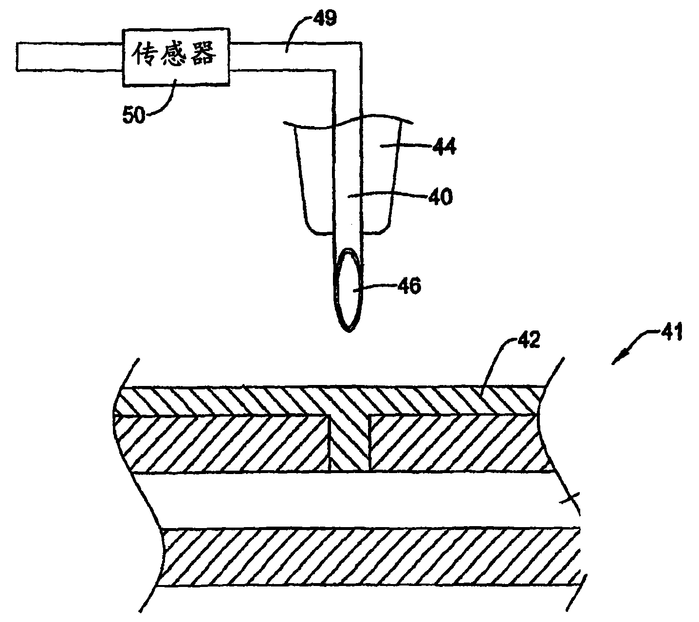
图2是一种说明性的流体分析仪的示意性的局部截面侧视图,其包括位于仪器/标本盒界面中的针具;2 is a schematic partial cross-sectional side view of an illustrative fluid analyzer including a needle located in the instrument/cartridge interface;
图3是图2说明性的实施例的示意性的局部截面侧视图,其中流检测器与针具对准;3 is a schematic partial cross-sectional side view of the illustrative embodiment of FIG. 2 with the flow detector aligned with the needle;
图4是另一个说明性的流体分析仪的示意图,其包括两个(或更多个)位于仪器/标本盒界面中的针具;4 is a schematic diagram of another illustrative fluid analyzer including two (or more) needles located in the instrument/cartridge interface;
图5是另一个说明性的仪器/标本盒界面的示意性的局部截面侧视图;5 is a schematic partial cross-sectional side view of another illustrative instrument/cartridge interface;
图6是又一个说明性的仪器/标本盒界面的示意性的局部截面侧视图;6 is a schematic partial cross-sectional side view of yet another illustrative instrument/cartridge interface;
图7是另一个说明性的仪器/标本盒界面的示意性的局部截面侧视图;7 is a schematic partial cross-sectional side view of another illustrative instrument/cartridge interface;
图8是用于确定标本盒上的流率的说明性的实施例的示意性的局部截面侧视图;8 is a schematic partial cross-sectional side view of an illustrative embodiment for determining flow rate on a cartridge;
图9是另一个用于确定标本盒上的流率的说明性的实施例的示意性的局部截面侧视图;9 is a schematic partial cross-sectional side view of another illustrative embodiment for determining flow rate on a cartridge;
图10是一种说明性的流体分析仪的示意性的局部截面侧视图,其包括标本盒和仪器,标本盒具有可塌缩的流通道,仪器具有用于可控制地使流通道塌缩的辊子;10 is a schematic partial cross-sectional side view of an illustrative fluid analyzer including a specimen cartridge having a collapsible flow channel and an instrument having means for controllably collapsing the flow channel. Roller;
图11是另一个说明性的流体分析仪的示意性的局部截面侧视图,其具有标本盒和仪器,标本盒具有可塌缩的流通道,仪器具有用于可控制地使流通道塌缩的辊子;11 is a schematic partial cross-sectional side view of another illustrative fluid analyzer having a specimen cartridge with a collapsible flow channel and an instrument with a device for controllably collapsing the flow channel. Roller;
图12是标本盒的示意性的顶视图,其包括许多齿轮,用于在标本盒的流通道中引起流动;Figure 12 is a schematic top view of a cartridge including a number of gears for inducing flow in the flow channel of the cartridge;
图13是一种说明性的流体分析仪的示意图,其包括带有检测器的仪器,检测器用于确定流体在标本盒的流通道中的流率和/或当前位置;且13 is a schematic diagram of an illustrative fluid analyzer including an instrument with detectors for determining the flow rate and/or current position of a fluid in a flow channel of a cartridge; and
图14A-14B是一种说明性的流体分析仪的示意图,其包括带有两个(或更多个)检测器的仪器,检测器用于确定流体在标本盒的流通道中的流率和/或当前位置。14A-14B are schematic diagrams of an illustrative fluid analyzer comprising an instrument with two (or more) detectors for determining the flow rate and/or current location.
详细描述A detailed description
以下细节将参照附图进行阅读,其中相似的标号表示贯穿若干视图中的相似的元件。详细描述和附图显示了若干实施例,其对此主张的发明是说明性的。The following details will be read with reference to the drawings, wherein like numerals refer to like elements throughout the several views. The detailed description and drawings show several embodiments, which are illustrative of the claimed invention.
本发明大致涉及流体分析仪,更具体地说,涉及具有一个或多个流体仪器-标本盒界面的流体分析仪。在某些实施例中,流体分析仪可以是流式血细胞计数器、血液分析仪、临床化学分析仪(例如葡萄糖分析仪、离子分析仪、电解质分析仪、溶解气体分析仪等等)、尿液分析仪或任何其它合适的分析仪,该分析仪在仪器和一次性标本盒之间具有一个或多个无泄漏的界面。The present invention relates generally to fluid analyzers, and more particularly to fluid analyzers having one or more fluid instrument-cartridge interfaces. In certain embodiments, the fluid analyzer may be a flow cytometer, blood analyzer, clinical chemistry analyzer (eg, glucose analyzer, ion analyzer, electrolyte analyzer, dissolved gas analyzer, etc.), urinalysis instrument or any other suitable analyzer having one or more leak-free interfaces between the instrument and the disposable cartridge.
图1是说明性的便携式血细胞计数器的透视图。说明性的血细胞计数器10包括仪器12和可拆卸的、且在某些情况下一次性使用的标本盒14。说明性的仪器12包括底座16、盖板18和将底座16附连在盖板18上的铰链20。底座16可包括光源22a和22b,以及相关联的光学器件和用于血细胞计数器的运行所必需的电子器件。盖板12可包括光检测器24a和24b及相关联的光学器件。FIG. 1 is a perspective view of an illustrative portable blood cell counter. The
可拆卸的标本盒14可通过样本收集器端口32接收样本流体,例如血液样本。帽38可用来当不使用可拆卸的标本盒14时保护样本收集器端口。可拆卸的标本盒14可执行血液稀释、红细胞溶解和用于形成芯的流体动力聚焦。可拆卸的标本盒14可构造成类似于可从Micronics Technologies得到的流体回路,其中一些流体回路是使用带有蚀刻通道的分层结构制造而成的。The
在使用过程中,当盖板18处于打开位置时,将可拆卸的标本盒14插入在仪器中。可拆卸的标本盒14可包括在底座16中用于容纳定位销28a和28b的孔26a和26b,这些销可有助于在不同部件之间提供对准和联接。可拆卸的标本盒14还可包括透明的流窗(flow streamwindow)30a和30b,这些流窗与光源22a和22b,以及光检测器24a和24b的阵列保持对准。During use, the
为了开始测试,可将盖板18升高,并将新的标本盒14放置且配准在底座16上。将样本流体引入样本收集器32中。然后关闭盖板18。在某些情况下,可拆卸的标本盒14提供血液稀释、红细胞溶解和用于芯形成的流体动力聚焦。在某些情况下,仪器12执行白细胞的血细胞计数测量。例如,光源22a和22b、光检测器24a和24b以及相关联的控制和处理电子器件可基于光散射和/或萤光信号而执行白细胞的区分和计数。根据需要还可设想使用滑动标本盒槽或任何其它适合的结构而不是使用用于壳体12的铰链结构。To begin testing, the
为了执行这种分析,可能需要推动(或拉动)样本流体(例如血液样本),使其穿过标本盒14的一个或多个流通道。还可能需要推动(或拉动)试剂和/或其它流体,使其穿过一个或多个流通道。在某些情况下,仪器12可能有助于在标本盒中产生必要的流体的流动,以穿过一个或多个仪器/标本盒界面。仪器12可备选或附加地用于监测和/或控制标本盒上的流量。To perform such an analysis, it may be necessary to push (or pull) a sample fluid (eg, a blood sample) through one or more flow channels of
图2是一种说明性的流体分析仪的示意性的局部截面侧视图,其包括位于仪器/标本盒界面中的针具。在说明性的实施例中,标本盒41显示为具有由流通道壁限定的流通道48。流通道48设于标本盒41的上主表面43和下主表面45之间。在某些情况下,流通道48可以是标本盒41中长而细的流通道。然而,根据需要可设想流通道48采用任何合适的尺寸或形状。在说明性的实施例中,在流通道48和上主表面43之间提供了开口47。2 is a schematic partial cross-sectional side view of an illustrative fluid analyzer including a needle located in the instrument/cartridge interface. In the illustrated example,
隔膜42设置在开口47中或开口47的上方,以形成不透流体的密封。在某些情况下,隔膜42还在标本盒41的整个上主表面43或其一部分上延伸,如图所示,但这不是必需的。隔膜42可防止或基本防止流体流过流通道48中的开口47并流出标本盒41。
隔膜42可适合于容许某一物体,例如针具40或任何其它合适的物体刺破隔膜42,并变得与流通道48流体连通。隔膜42还可在针具40周围形成密封,以防止或基本防止流体在针具40的外面和隔膜42之间穿过。隔膜42还可适合于在从隔膜42中除去针具40之后,重新密封由针具40产生的开口。在某些情况下,当抽出针具40时,隔膜42还可擦拭针具40,以帮助除去针具40上的残留流体。隔膜42可由例如弹性和/或柔性材料制成,例如弹性体(如橡胶)等等。The
在说明性的实施例中,针具40具有伸长的管状主体,其带有空心的芯部,以容许流体流过。该主体一端可连接在仪器上。针具40的另一端可终止于尖端46处,其可适合于穿过隔膜42而插入到标本盒41中。在说明性的实施例中,尖端包括渐缩的尖头,此尖头可容许针具更容易地刺破隔膜42,而不会使隔膜42去芯(coring)。然而,根据需要可设想使用任何合适的针具40的尖端。In the illustrated embodiment,
在某些实施例中,针具40还可具有止动机构44,该止动机构44设置在针具40的主体周围,并相对于针具主体进行固定。止动机构44可横向向外地从主体延伸一段距离,并可从针具40的尖端46偏离一段偏移距离。止动机构44可有助于将针具40插入到一致的且合适的深度。在说明性的实施例中,针具40可刺破隔膜42,并可向下移动,直到针具的尖端46与流通道48成流体连通,并且止动机构44与隔膜42(或标本盒41)的顶面接合时为止。在完全插入针具40的情况下,在需要时,可设定止动机构的偏移距离,以帮助确保针具40的尖端46不与流通道48的内侧壁51接合。因而,在某些说明性的实施例中,止动机构44可帮助防止针具40插入到标本盒中过深或过浅。In some embodiments, the
当插入时,针具40的尖端46的中空开口可用于在仪器(见图1)和标本盒41的流通道48之间传送流体和/或压力。在某些情况下,仪器可提供流体和/或压力,其在标本盒41的流通道48中形成所需的流。The hollow opening of the
例如,在某些情况下,仪器可在其上具有流体储槽。根据需要,流体可以是例如试剂流体、细胞溶解流体、鞘液、推动流体或任何其它合适的流体。来自仪器的流体可通过针具40而提供给标本盒41的流通道48,并在流通道48中产生流体的流动。在某些情况下,通过知晓流体离开仪器所处的流率,即可确定和/或控制流通道48中的流量。For example, in some cases, an instrument may have a fluid reservoir thereon. The fluid may be, for example, a reagent fluid, a cell lysis fluid, a sheath fluid, a push fluid, or any other suitable fluid, as desired. Fluid from the instrument may be provided to the
设想标本盒41是可拆卸的,或甚至是一次性使用的。在某些实施例中,可拆卸的标本盒41可插入仪器中,该仪器适合于容纳标本盒41。该仪器可包括,例如底座、盖板和针具41。一旦插入,仪器的盖板即关闭。在某些情况下,仪器的针具40可能已经与隔膜充分对准,而在其它情况下,针具40可能需要对准。一旦对准,可朝着标本盒41促动针具40,并可刺破隔膜42且移动到使针具40的尖端46与标本盒41的流通道48成流体连通的位置。在某些情况下,针具40的促动或运动可以是自动化的,例如通过电动机等,其促动针具40,使针具40在插入位置和抽出位置之间移动。控制器可用来控制电动机。备选地设想例如通过手动地将针具40插入标本盒41和从标本盒41中抽出针具40,从而手动地将针具40移动到位。It is contemplated that the
一旦将针具40插入到标本盒41中,且尖端46的开口定位在标本盒41的流通道48中,就可将流体以受控的流率从仪器传送到标本盒41的流通道48中。根据需要,流体可以是气体或液体。在自动化过程中,如果需要,还可由控制器控制流率。Once the
在针具40和仪器将所需的流体输送给标本盒41之后,可抽出针具40,从而可从仪器上除去标本盒41,并且在某些情况下,妥善地处置掉标本盒41。同样,根据需要可自动化地或手动地执行针具40的抽出。在某些情况下,当从标本盒41中抽出针具40时,由隔膜42擦去针具40上的残留流体。After the
在某些情况下,可确定由仪器提供的流体流率,以及该流率与标本盒41中的样本流率的相关性。这可提供一种相对容易的方式,以精确地确定和/或控制标本盒41的流通道48中的样本流体的流率。In some cases, the fluid flow rate provided by the instrument and its correlation to the sample flow rate in the
在测量之前,可设想在将针具40插入到标本盒41中之前,仪器可用流体冲洗针具40的主体和尖端46。这可有助于除去标本盒间可能的污染源。在测量结束时,针具40的主体和尖端46的外表面在抽出期间可由隔膜42擦拭,这也有助于除去可能的污染源。另外,针具40的尖端46的小尺寸或小的表面积可帮助减少可能是污染源的样本流体的数量。Prior to measurement, it is envisioned that the instrument may flush the body and
在某些情况下,可引入热消毒过程,以便在标本盒测量之间对针具40的尖端46进行消毒。例如,消毒过程可以是快速的加热和冷却循环,其类似于传热针(heat transfer pin)的消毒过程。在某些情况下,根据需要可在每次使用针具40之后提供该过程。另外,可在仪器和/或标本盒41中提供单向阀,该单向阀可帮助防止流体回流到仪器和/或标本盒41中。这在功率损耗期间可能特别有用。In some cases, a heat sterilization process may be incorporated to sterilize the
图3是图2的说明性的实施例的示意性的局部截面侧视图,其中传感器50与针具40对准。如图所示,传感器50检测仪器的供给流通道49中的流体特征。传感器50可测量例如,当流体仍处于仪器中时,或换句话说,在流体通过针具40而离开仪器之前的流率、压力或其它特征。在一个说明性的实施例中,传感器50可以是热力式风速仪类型的流传感器,例如在美国专利No.4,478,076、美国专利No.4,478,077、美国专利No.4,501,144、美国专利No.4,651,564、美国专利No.4,683,159和美国专利No.5,050,429中所述的流传感器,所有这些专利都通过引用而结合在本文中。然而,根据需要可设想传感器50是任何合适类型的流传感器。FIG. 3 is a schematic partial cross-sectional side view of the illustrative embodiment of FIG. 2 with
通过将传感器50定位在仪器的流通道49的附近,传感器50能够直接测量穿过针具40的流体的流率。通过知晓穿过针具40的流率,还可确定标本盒的流通道48中的流率。可使用传感器50备选或另外地检测一个或多个流体特征,例如热导率、比热、流体密度、电阻率和/或其它流体特征,以便例如帮助识别或核实穿过流通道49的流体是预期的流体或预期的流体类型。这可有助于在特殊的分析或过程期间核实在流通道48中事实上正在使用预期的流体。By positioning the
传感器50可联接在仪器的控制器(未显示)上。根据需要,控制器可发送信号以触发传感器50,并且可发送信号,以使传感器50不起作用。反过来,根据需要,传感器50可将有关正在穿过流通道49的流体的流率或其它特征的数据提供给控制器。传感器50可备选或另外地定位在标本盒41上,并且可用于,例如直接测量标本盒41的流通道48中的流率。然而,这会增加标本盒41的成本。
图4是另一个说明性的流体分析仪的示意图,该流体分析仪包括两个(或更多个)位于仪器/标本盒界面中的针具40和52。在一个说明性的实施例中,标本盒41包括第一流通道48a和第二流通道48b。第一流通道48a和第二流通道48b由壁53分隔开,如图4中的交叉虚影线所示。例如,第一针具40可从标本盒41的第一流通道48a中抽取流体,并且第二针具52可将流体返回至标本盒41的第二流通道48b中。仪器可具有将第一针具40和第二针具52流体连通的流通道55。流传感器50可设置成与仪器的流通道55成一条直线,并可提供对标本盒的第一流通道48a和/或第二流通道48b中的流率的测量。通过将流传感器50移动到仪器上,而不是在标本盒41上提供流传感器50,可降低标本盒41的成本。传感器50可备选或另外地用来检测一个或多个流体特征,例如热导率、比热、流体密度、电阻率和/或其它流体特征,从而例如帮助识别或核实正在穿过标本盒的第一流通道48a和/或第二流通道48b的流体是预期的流体。这可有助于在特殊的分析或过程期间核实在第一流通道48a和/或第二流通道48b中事实上正在使用预期的流体。FIG. 4 is a schematic diagram of another illustrative fluid analyzer that includes two (or more) needles 40 and 52 located in the instrument/cartridge interface. In one illustrative embodiment,
在使用期间,第一针具40和第二针具52可穿过它们相应的隔膜而同时地或顺序地插入到标本盒41中。这种插入可类似于上面参照图2所述。一旦将针具40和52都插入到标本盒41中,第一针具40可从标本盒41中的流通道48a抽取流体,并促使其流过“空闲的”流通道55。当处于“空闲的”流通道55中时,传感器50可测量流体的流率(和/或其它特征)。在测量流率之后,可将流体传送到第二针具52中,在此处其返回到标本盒41的流通道48b中。在使用了标本盒41之后,可从标本盒41中抽出针具40和52,其同样类似于上面参照图2所述。During use, the
在另一说明性的实施例中,可能不存在如图4中用交叉虚影线所示的壁53。也就是说,第一针具40和第二针具52可进入被标为48的公共流通道。第二针具52可定位在第一针具40的上游或下游。在这种构造下,第一针具40可将第一压力传送给传感器50,并且第二针具52可将第二压力传送给传感器50。传感器可以是例如压差传感器。从沿着流通道48的两个位置上所检测的压力差,可确定沿着流通道48的流率。如果需要在流通道48中可在第一针具40和第二针具52之间设置限制,以增加它们之间的压差。如果需要,可设想将上面论述的针具设于可拆卸的标本盒上,并且可将相应的隔膜放置在仪器上。In another illustrative embodiment,
图5是另一个说明性的仪器/标本盒界面的示意性的局部截面侧视图。在此说明性的实施例中,仪器可包括带有相对较刚性的末端63的柱塞60。根据需要,柱塞可以是例如螺钉、活塞或任何其它合适的装置。在螺钉型柱塞的情况下,可设想该螺钉可以是细节距螺钉。然而根据需要,可使用任何合适的螺钉。5 is a schematic partial cross-sectional side view of another illustrative instrument/cartridge interface. In this illustrative example, the instrument may include a
在说明性的实施例中,柱塞60附连在仪器上,或是仪器的一部分,并且可由促动器上下促动。在某些情况下,促动器可由自动化过程进行控制。在这种情况下,仪器可包括电动机(未显示),例如微步进式电动机,以控制柱塞60的位置。备选地,可设想在某些情况下,根据需要可手动提供柱塞60的促动,例如,通过杠杆、压力按钮或任何其它手工方法。In the illustrated embodiment,
在说明性的实施例中,可拆卸的标本盒61可具有可在其中存储流体的流体存储空腔66,其由存储空腔66的壁限定。在一种情况下,流体存储空腔66可以是圆柱形的存储空腔66,其具有比高度相对较大的半径,从而装配在相对较薄的一次性标本盒上。然而,根据需要可设想存储空腔66采用任何合适的尺寸或形状。说明性的存储空腔66流体连通地联接在标本盒61的流通道64上。In an illustrative embodiment,
在多数情况下,存储空腔66的一个或多个壁的至少一部分是标本盒61的外壁,其可包括隔膜62。在某些情况下,隔膜62可以是弹性和/或柔性隔膜,例如合成橡胶隔膜。在某些情况下,通过首先除去标本盒61的一部分,以限定形成存储空腔66的开口,从而可提供隔膜62。这样,可将隔膜62布置在开口中和/或开口上,并且在某些情况下,布置在标本盒61的上表面的一部分上,以形成不透流体的密封。In most cases, at least a portion of one or more walls of
开口的尺寸可大于柱塞60的末端63,因而容许柱塞60变形,并使隔膜62移动到存储空腔66中。在某些情况下,布置在开口上的隔膜62的部分可从标本盒61的上表面67凹陷下去。这种凹陷的隔膜62可帮助防止隔膜62的意外的压缩或移位,这会导致偶然地引起标本盒61的流通道64中的流动。The size of the opening may be larger than the
说明性的实施例可通过使柱塞60抵靠隔膜62移动,使隔膜62朝着存储空腔66变形和移位而引起标本盒61的流通道64中的流体的流动,这又使存储在存储空腔66中的流体沿着流通道64而移动。The illustrative embodiment can cause the flow of fluid in the
在使用期间,可首先将标本盒61定位在仪器中。在某些情况下,仪器可使柱塞60与标本盒61的存储空腔66对准。接下来,仪器可使柱塞60移动成与隔膜62相接触,但仍不使隔膜62移动。之后仪器可驱动柱塞60进入隔膜62,使隔膜62移动到存储空腔66中,并在标本盒的流通道64中产生流动。然后仪器可抽出柱塞60。在某些情况下,可以脉冲方式或稳定的方式来促动柱塞60。更一般地说,可设想仪器使柱塞60以某一速率曲线移动,这在标本盒61的流通道64中产生所需的流率。在说明性的实施例中,隔膜62可有助于用作仪器和标本盒61的流体之间的物理屏障。具有这种屏障可减少标本盒61和/或仪器被污染的风险。During use, the
图6是又一个说明性的仪器/标本盒界面的示意性的局部截面侧视图。这个说明性的实施例类似于图5,除了柱塞70包括弹性和/或柔性隔膜78以外,该隔膜可通过流体压力而扩张(例如膨胀),以使隔膜62移动到存储空腔66中,这又在标本盒61的流通道64中引起流动。更具体地说,柱塞70可具有附连在仪器上的第一端,和定位在标本盒61的隔膜62附近的第二端。在柱塞70的轴向方向上可提供一个或多个流通道79a和79b。所述一个或多个流通道79a和79b可在仪器内的压力源和弹性和/或柔性隔膜78后面的空腔之间形成压力传导路径。轴70可联接在控制器上,控制器控制轴70的(上/下)运动和/或流体(气体或液体)的流动,流体穿过一个或多个流通道79a和79b而流入到轴70的轴顶附近的空腔中。6 is a schematic partial cross-sectional side view of yet another illustrative instrument/cartridge interface. This illustrative embodiment is similar to FIG. 5, except that
在使用期间,首先可将标本盒61定位在仪器中。在某些情况下,仪器可使轴70与标本盒61的存储空腔66对准。接下来,如果需要,仪器可使轴70移动成与隔膜62相接触,但仍不使隔膜62移动。然后仪器可使轴70的弹性和/或柔性隔膜78后面的空腔膨胀,这使隔膜62移动到存储空腔66中,并在标本盒61的流通道64中产生流。然后仪器可使弹性和/或柔性隔膜78后面的空腔收缩,并抽出轴70。在某些情况下,弹性和/或柔性隔膜78后面的空腔的膨胀可以脉冲方式或稳定的方式实现。更一般地说,设想仪器可控制弹性和/或柔性隔膜78后面的空腔以某一速率曲线进行膨胀,这在标本盒61的流通道64中产生所需的流率。根据应用,这种说明性的过程可以是自动控制的或手动控制的。During use, the
图7是另一个说明性的仪器/标本盒界面的示意性的局部截面侧视图。该说明性的实施例包括仪器,该仪器具有用来为标本盒81的流通道84提供所需流率的喷嘴80。喷嘴80可流通地联接在压力源(未显示)上,以便为喷嘴80提供加压(正压或负压)流体(气体或液体)。根据需要,压力源可以是气压泵、压缩的气体源或任何其它合适的压力源。7 is a schematic partial cross-sectional side view of another illustrative instrument/cartridge interface. This illustrative embodiment includes an instrument having a
喷嘴80可具有附连在仪器上的第一端和适合于与标本盒81相接合的第二端。标本盒81可具有一端具有流通道开口的流通道84。在某些情况下,可存在存储空腔86,其流通地联接在流通道84上,用于储藏一定体积的流体,例如样本流体(例如血液)。在某些情况下,流通道开口可具有单向阀82。单向阀82可具有容许流体或气体沿一个方向穿过,但禁止或大体上禁止气体或流体沿另一个方向穿过的特征。在某些情况下,可配置阀门82以防止来自标本盒81的流体和/或气体的回流,在某些情况下,这可帮助减少仪器或周围空间的污染风险。
在某些情况下,说明性的喷嘴80可包括位于靠近标本盒81的第二端处的垫圈或密封件。另外,或作为备选,标本盒81可包括围绕标本盒81的流通道开口的垫圈或密封件。垫圈或密封件可有助于在喷嘴80和标本盒81之间提供无泄漏的界面。在某些情况下,密封件可以是不透气的,从而不会漏出空气或流体。密封件还可有助于通过防止流体从界面漏出而减少污染。In some cases, the
为了在样本流体中引起流动,可将标本盒81插入并安装在仪器中(参见例如图1)。在某些情况下,然后可将标本盒81中的开口与喷嘴80的开口对准。在其它情况下,标本盒81在仪器中的安装自动地确保了标本盒81中的开口完全与喷嘴80中的开口对准。然后可使喷嘴80与标本盒81形成接合,以便在其之间提供无泄漏的界面。喷嘴80可以自动或手动的方式向下移动至标本盒81上。例如,可使用电动机等使喷嘴80移动而与标本盒81形成接合。作为备选,使用者可手动地移动喷嘴80,使其与标本盒81形成接合,例如通过关闭仪器的盖板(参见例如图1)。To induce flow in the sample fluid, a
一旦被定位并密封,就可通过仪器将压力应用于标本盒开口和流通道84中。例如,可通过喷嘴80将流体或气体泵送到流通道84中而应用压力。泵送到流通道84中的流体或气体可使流通道84中的流体移动,并引起流动。在某些情况下,泵送到流通道84中的流体或气体可使包含在存储空腔86中的样本流体(例如血液)移动。Once positioned and sealed, pressure may be applied by the instrument to the cartridge opening and flow
在某些实施例中,可在流通道84中提供可移动的止动器或类似装置(未显示)。通过喷嘴80泵送到流通道84中的流体或气体可位于止动器的上游侧,并且已经处于流通道84中的流体或气体(例如样本流体)可位于止动器的下游侧。通过喷嘴80泵送到流通道84中的流体或气体可使止动器沿着流通道而移动,从而引起已经处于流通道84中的流体或气体流动。止动器可使经由喷嘴80泵送到流通道84中的流体或气体与已经处于流通道84中的流体或气体分隔开。当需要时,这可有助于防止经由喷嘴80泵送到流通道84中的流体或气体与已经处于流通道84中的流体或气体混合。In some embodiments, a movable stop or similar device (not shown) may be provided in the
图8是用于确定标本盒上的流率的说明性的实施例的示意性的局部截面侧视图。该说明性的实施例包括喷嘴90和标本盒91,类似于上面参照图7中所述。在此实施例中,标本盒91可带有至少一个开口的具有流通道92,该开口适合于与喷嘴90的开口96成流体连通。在某些情况下,可在流通道92中提供限制94,其容许流体对于由喷嘴90提供的给定的输入压力以已知的流率穿过流通道92。限制94可以是流通道92本身,或者可以是单独的特征,例如减小的流通道92的截面。8 is a schematic partial cross-sectional side view of an illustrative embodiment for determining flow rate on a cartridge. This illustrative embodiment includes a
为了确定流体穿过流通道92的流率,可检测限制94两侧的压力。通过例如仪器自身的压力检测器等可检测位于限制94的喷嘴90侧的压力。利用标本盒上的压力检测器可测量限制94下游侧的压力。作为备选,在该限制的下游可提供压力表接头98。压力表接头98可包括与仪器的界面,并且该仪器可包括压力检测器,以便通过压力表接头98确定压力。该界面可包括任何类型的仪器/标本盒界面,包括本文所述的那些界面。在某些情况下,根据需要可设想使用多个压力表接头。To determine the flow rate of fluid through
图9是另一个用于确定标本盒上的流率的说明性的实施例的示意性的局部截面侧视图。此说明性的实施例类似于参照图8所示和所述,除了在标本盒101上设有两个压力表接头104和106,所述压力表接头在限制102的一边有一个。压力表接头104和106可具有类似于图8的与仪器的界面。用两个已知的压力,可确定流体的流率。9 is a schematic partial cross-sectional side view of another illustrative embodiment for determining flow rate on a cartridge. This illustrative embodiment is similar to that shown and described with reference to FIG. 8 , except that two
图10是说明性的流体分析仪的示意性的局部截面侧视图,其包括标本盒111和仪器,标本盒111具有可塌缩的流通道114,仪器具有用于可控制地使流通道114塌缩的辊子110。在此说明性的实施例中,标本盒111包括流通道114,该流通道114由流通道114的壁限定。至少其中一个流通道114的壁可至少部分地包括可塌缩的隔膜112。在某些情况下,可塌缩的隔膜112可限定流通道114的外壁的至少一部分。另外,在某些情况下,流通道114的其它壁可以是刚性的。根据需要,说明性的隔膜112可以是弹性体或任何其它柔性材料。作为备选,说明性的隔膜112可以是相当刚性的材料,该材料可在流通道114周围仍保持不透流体的密封的同时被塌缩。10 is a schematic partial cross-sectional side view of an illustrative fluid analyzer including a
仪器可包括辊子110,其用于在安装在仪器上之后,对标本盒111的可塌缩隔膜112施加压力。在一种情况下,辊子110可将作用力应用于可塌缩的隔膜112上,使流通道114塌缩,并继续沿着隔膜112滚动,使更多的流通道114塌缩。在另一个实施例中,辊子110可包括多个从仪器朝着标本盒111延伸的轴。这些轴与可塌缩的隔膜112长时间地接合,顺序地对位于一端的第一轴所延伸的地方施加作用力,并使隔膜112塌缩,之后下一个相邻的轴使隔膜112塌缩等等,直至所有的轴都得以延伸,并因而使流通道114完全塌缩时为止。更一般地说,根据需要可设想辊子110是任何用来对可塌缩的隔膜112施加作用力的合适的装置110。根据需要还可设想辊子110所施加的作用力可以是稳定的力、滚轧力、脉冲式作用力或任何其它合适的方法。此外,辊子110可联接在用于自动控制辊子110的控制器上,或者,可设想辊子110是手动控制的。在自动化的情形下,辊子110可联接在电动机等装置上,该装置受到仪器的控制器的控制。The instrument may include
在使用期间,可首先将标本盒111插入并安装在仪器中,使得辊子110与可塌缩的隔膜112对准。接下来,可将辊子110定位在隔膜112的附近。当准备好在流通道114中产生流动时,可触动辊子110,以施加足够的作用力,从而使可塌缩的隔膜112的一部分塌缩。辊子110可继续沿着流通道114的长度施加作用力,以便在流通道114中引起持续的流动。通过流通道114的截面积与辊子110的作用力和速度可确定样本流体的流率。During use, the
如果可塌缩的隔膜112太柔软,那么对可塌缩的隔膜112的一部分施加的作用力可能造成流通道114中的流体对隔膜112的另一部分产生作用力,这可能造成可塌缩的隔膜112在一定程度上鼓起来或膨胀。这可能产生辊子110的位置的非线性以及流通道114中所引起的实际流量的非线性。这种非线性可通过校准仪器进行补偿。If the
作为备选,在某些情况下,当可塌缩的隔膜的另一部分被塌缩时,可塌缩的隔膜112适合于不向外鼓起来或变形。例如,可塌缩的隔膜112可由抵抗这种鼓凸的相对较刚性的材料制成。备选或附加地可将另一物体连接在可塌缩的隔膜112的上方,以帮助防止这种变形。当辊子110具有多个轴的情况下,所有的轴都可在对第一轴施加任何作用力之前降低至可塌缩的隔膜处或其附近,从而可防止或大体上防止隔膜112发生任何不需要的外面变形。Alternatively, in some cases, the
图11是另一个说明性的流体分析仪的示意性的局部截面侧视图,其具有标本盒和仪器,标本盒具有可塌缩的流通道,仪器具有用于可控制地使流通道塌缩的辊子。在此说明性的实施例中,仪器可包括辊子120,其适合于将作用力施加于标本盒121上,类似于参照图10所示和所述。标本盒121可包括流通道124,该流通道124由流通道124的壁包括顶壁和底壁限定。在一个实施例中,流通道124可通过具有被铰接的第一端而可塌缩,使得流通道124的顶壁和底壁形成枢轴点,如图所示。当将作用力施加于流通道124的顶面上时,铰链可容许顶面向底面塌缩,从而沿着流通道124挤压流体。在某些情况下,流通道124的顶面可具有由柔性隔膜122,例如弹性隔膜122包围的刚性结构,从而当暴露于作用力下时,隔膜122容许顶面与底面形成接触。更一般地说,根据需要可设想使用任何合适的方法来使流通道124塌缩。11 is a schematic partial cross-sectional side view of another illustrative fluid analyzer having a specimen cartridge with a collapsible flow channel and an instrument with a device for controllably collapsing the flow channel. Roller. In this illustrative embodiment, the instrument may include
图12是标本盒的示意性的顶视图,标本盒包括许多齿轮,用于在标本盒的流通道中引起流动。该说明性的实施例包括具有流通道136和腔室138的标本盒131。腔室138包括许多齿轮132和134。齿轮132和134可形成泵,其能够泵送流体,以引起流通道136中的流动。在某些情况下,各齿轮132,134可具有多个围绕齿轮周边的桨状结构。桨状结构可帮助推动流体穿过腔室138。如图所示,两个齿轮132和134可按彼此相反的方向旋转,并可推动围绕腔室138周围的样本流体或齿轮132和134之间的样本流体。更一般地说,根据需要可设想使用一个、两个、三个或任何数目的齿轮132和134,以产生所需的流量。Figure 12 is a schematic top view of a cartridge including a number of gears for inducing flow in the flow channel of the cartridge. This illustrative embodiment includes a
在某些情况下,可由电动机和轴驱动齿轮132和134。在其它情况下,可由电场或磁场驱动齿轮132和134。更一般地说,可设想由任何合适的方法来驱动齿轮132和134。In some cases, gears 132 and 134 may be driven by electric motors and shafts. In other cases, gears 132 and 134 may be driven by electric or magnetic fields. More generally, it is contemplated that gears 132 and 134 may be driven by any suitable method.
在说明性的实施例中,仪器可包括用于齿轮132和134的驱动机构的至少一部分。例如,仪器可包括电动机和轴,其中轴与一个或多个齿轮132和134对接。作为备选,齿轮132和134可包括铁质材料或甚至是磁化的,并且仪器可提供驱动齿轮132和134的旋转磁场。仪器的驱动机构可由控制器控制。根据需要控制器可控制齿轮132和134的操作,例如,齿轮132和134的起动和制动、齿轮132和134的旋转速度、齿轮132和134的旋转方向和/或任何其它参数。In an illustrative embodiment, an instrument may include at least a portion of a drive mechanism for
图13是说明性的流体分析仪的示意图,该分析仪包括带有检测器的仪器,检测器用于确定在标本盒的流通道中的流体的流率和/或当前位置。该说明性的实施例包括具有流通道140的标本盒141。在该仪器中可提供检测器142。在一个实施例中,检测器142可安装在与标本盒141的流通道140相邻的仪器。检测器142可光学地、电气地、磁性地或通过任何其它合适的方法检测流体的存在或某些特征。在某些情况下,例如对于光学检测,标本盒141可为检测器142提供窗口,以查看流通道140中的流体。可设想检测器142可联接在控制器上,用于触发检测器142和使检测器142不起作用,和/或用于接收来自检测器142的数据。13 is a schematic diagram of an illustrative fluid analyzer including an instrument with detectors for determining the flow rate and/or current position of fluid in a flow channel of a cartridge. This illustrative embodiment includes a
在某些情况下,为了测量标本盒141中的样本流体144的流率,可有另一种流体,例如推动流体146,其推动样本流体144穿过标本盒141。根据需要可通过前述的任何方法或任何其它合适的方法将推动流体146提供给标本盒141。另外,推动流体146可包括由检测器142测量的某些可检测的特征,例如,可光学地、电气地或磁性地检测的粒子。因而,为了确定样本流体144的流率,可检测和确定推动流体146的流率。In some cases, to measure the flow rate of
相似的方法可用于确定流体沿着流通道何时到达某点。也就是说,可将检测器142定位在沿着流通道的位置附近,并且根据需要检测器142可光学地、电气地或磁性地检测流体在该位置的存在。例如,根据需要,这可用于检测样本流体例如血液何时已经完全充满样本流体输入通道,鞘液或细胞溶素流体何时到达标本盒141上的流体回路中的某个点,或用于任何其它合适的目的。A similar approach can be used to determine when a fluid has reached a point along a flow channel. That is, the
图14A-14B是说明性的流体分析仪的示意图,该分析仪包括带有两个(或更多个)检测器的仪器,检测器用于确定流体在标本盒的流通道中的流率和/或当前位置。该说明性的实施例包括两个附连在仪器上的检测器152和154。还提供了标本盒151,其包括流通道150。类似于图13,检测器152和154可根据需要光学地、电气地、磁性地或通过任何其它合适的方法而检测流通道150中的流体的存在和/或流率。在某些情况下,标本盒151可具有两个或更多个用于流通道150的窗口,以观察流通道150中的流体。两个或更多个检测器可设于彼此间隔开的已知距离处。根据需要各检测器可联接在控制器上,以从检测器152和154接收数据和/或传送数据至检测器152和154。14A-14B are schematic diagrams of an illustrative fluid analyzer comprising an instrument with two (or more) detectors for determining the flow rate and/or current location. The illustrative embodiment includes two detectors 152 and 154 attached to the instrument. A
通过例如提供沿着流通道156的流动可确定流体穿过流通道150的流率。在某些情况下,通过利用气体156,例如空气推挤流体158可提供这种流动。在说明性的实施例中,气体156或空气可用于推动流体,从而可易于检测样本流体158的终点,但这不是必须的。通过例如检测所有或基本上所有样本流体158何时经过各检测器,这两个或更多个检测器152和154可用来确定流体158的流率。控制器可确定流体158经过各检测器152和154所消逝的时间,并知晓检测器152和154之间的距离,从而确定流体158的流率。图14A中显示了第一检测器152何时检测到样本流体158终点的说明性的时间点。图14B中显示了第二检测器154何时检测到样本流体158终点的说明性的时间点。作为备选或附加,第一检测器和第二检测器152和154可用来检测样本流体158何时到达以确定流率。在又一个实施例中,第一检测器和第二检测器152和154可用于检测流体的某些其它特征,例如温度、热导率等等。在流体中可产生热脉冲,然后检测器可检测到该热脉冲。检测器152和154还可检测流体的电阻率和/或其它特征。同样,流体可包含粒子,例如小珠等,其可光学地、电气地或磁性地检测到,以帮助确定流体的流率。根据应用可设想使用不止两个检测器,或只使用一个检测器。The flow rate of fluid through
虽然已经如此描述了本发明的优选实施例,但是本领域的技术人员应该懂得在所附权利要求的范围内可制作和使用其它的实施例。在前面所述的描述中已经陈述了本文所覆盖的许多本发明的优势。然而,应该懂得本发明公开在许多方面都仅仅是说明性的。在细节上,尤其在部件的形状、尺寸和排列方面可做出修改而不超出本发明的范围。当然,在表达所附权利要求的文字中限定了本发明的范围。Having thus described the preferred embodiment of the invention, it will be understood by a person skilled in the art that other embodiments can be made and used within the scope of the appended claims. Many of the advantages of the invention covered herein have been set forth in the foregoing description. It should be understood, however, that the present disclosure is, in many respects, only illustrative. Modifications may be made in details, especially in respect of the shape, size and arrangement of parts without departing from the scope of the invention. It is, of course, that the scope of the invention is defined in the language of the appended claims.
Claims (27)
Applications Claiming Priority (3)
| Application Number | Priority Date | Filing Date | Title |
|---|---|---|---|
| US11/306,399 US8182767B2 (en) | 2005-12-27 | 2005-12-27 | Needle-septum interface for a fluidic analyzer |
| US11/306,399 | 2005-12-27 | ||
| PCT/US2006/046748 WO2007075292A2 (en) | 2005-12-27 | 2006-12-07 | Needle-septum interface for a fluidic analyzer |
Publications (2)
| Publication Number | Publication Date |
|---|---|
| CN101641602A true CN101641602A (en) | 2010-02-03 |
| CN101641602B CN101641602B (en) | 2012-11-07 |
Family
ID=38134884
Family Applications (1)
| Application Number | Title | Priority Date | Filing Date |
|---|---|---|---|
| CN2006800533777A Expired - Fee Related CN101641602B (en) | 2005-12-27 | 2006-12-07 | Needle-Diaphragm Interfaces for Fluid Analyzers |
Country Status (5)
| Country | Link |
|---|---|
| US (1) | US8182767B2 (en) |
| EP (1) | EP1974221B1 (en) |
| JP (2) | JP2009521700A (en) |
| CN (1) | CN101641602B (en) |
| WO (1) | WO2007075292A2 (en) |
Cited By (3)
| Publication number | Priority date | Publication date | Assignee | Title |
|---|---|---|---|---|
| CN104380080A (en) * | 2012-07-04 | 2015-02-25 | 西门子公司 | Apparatus for determining the number of cells in a cell suspension |
| CN109061130A (en) * | 2018-08-06 | 2018-12-21 | 张岩锐 | A kind of device with urinalysis test strips |
| CN110856822A (en) * | 2018-08-22 | 2020-03-03 | 厦门大学 | Communicating vessel, combination of communicating vessel and reagent module and microfluidic chip |
Families Citing this family (38)
| Publication number | Priority date | Publication date | Assignee | Title |
|---|---|---|---|---|
| USRE49221E1 (en) | 2002-06-14 | 2022-09-27 | Parker Intangibles, Llc | Single-use manifolds for automated, aseptic handling of solutions in bioprocessing applications |
| US7857506B2 (en) * | 2005-12-05 | 2010-12-28 | Sencal Llc | Disposable, pre-calibrated, pre-validated sensors for use in bio-processing applications |
| EP1895308A1 (en) * | 2006-09-01 | 2008-03-05 | Agilent Technologies, Inc. | Droplet-based fluidic coupling |
| US10753927B2 (en) * | 2006-09-22 | 2020-08-25 | ALERE TECHNOLOGIES GmbH | Methods for detecting an analyte |
| US20080245740A1 (en) * | 2007-01-29 | 2008-10-09 | Searete Llc, A Limited Liability Corporation Of The State Of Delaware | Fluidic methods |
| US8490541B2 (en) * | 2007-03-20 | 2013-07-23 | Koninlijke Philips N.V. | Method for determining at least one suitable parameter for a process of making a beverage |
| GB0715171D0 (en) * | 2007-08-03 | 2007-09-12 | Enigma Diagnostics Ltd | Sample processor |
| WO2010085736A1 (en) * | 2009-01-23 | 2010-07-29 | University Of Maryland Baltimore County | Chlorophyll and turbidity sensor system |
| US10031061B2 (en) | 2009-05-13 | 2018-07-24 | Intellicyt Corporation | Flow measurement and control for improved quantification of particles in flow cytometry |
| US9700889B2 (en) | 2009-11-23 | 2017-07-11 | Cyvek, Inc. | Methods and systems for manufacture of microarray assay systems, conducting microfluidic assays, and monitoring and scanning to obtain microfluidic assay results |
| US10065403B2 (en) | 2009-11-23 | 2018-09-04 | Cyvek, Inc. | Microfluidic assay assemblies and methods of manufacture |
| US9855735B2 (en) | 2009-11-23 | 2018-01-02 | Cyvek, Inc. | Portable microfluidic assay devices and methods of manufacture and use |
| US9651568B2 (en) | 2009-11-23 | 2017-05-16 | Cyvek, Inc. | Methods and systems for epi-fluorescent monitoring and scanning for microfluidic assays |
| US9500645B2 (en) | 2009-11-23 | 2016-11-22 | Cyvek, Inc. | Micro-tube particles for microfluidic assays and methods of manufacture |
| WO2013134742A2 (en) * | 2012-03-08 | 2013-09-12 | Cyvek, Inc | Micro-tube particles for microfluidic assays and methods of manufacture |
| US9759718B2 (en) | 2009-11-23 | 2017-09-12 | Cyvek, Inc. | PDMS membrane-confined nucleic acid and antibody/antigen-functionalized microlength tube capture elements, and systems employing them, and methods of their use |
| ES2649559T3 (en) | 2009-11-23 | 2018-01-12 | Cyvek, Inc. | Method and apparatus for testing |
| WO2011065981A1 (en) | 2009-11-30 | 2011-06-03 | Intuity Medical, Inc. | Calibration material delivery devices and methods |
| WO2011161894A1 (en) * | 2010-06-22 | 2011-12-29 | コニカミノルタホールディングス株式会社 | Liquid-delivery device and test chip used in said device |
| JP2012118039A (en) * | 2010-11-12 | 2012-06-21 | Sony Corp | Microchip |
| WO2012129455A2 (en) | 2011-03-22 | 2012-09-27 | Cyvek, Inc | Microfluidic devices and methods of manufacture and use |
| JP5692164B2 (en) * | 2012-05-22 | 2015-04-01 | ウシオ電機株式会社 | Reagent supply method to microchip and reagent supply apparatus to microchip |
| US8858886B1 (en) | 2013-05-08 | 2014-10-14 | Agilent Technologies, Inc. | Scanning system with interchangeable optical cartridges for fluorescence measurements |
| US10191071B2 (en) | 2013-11-18 | 2019-01-29 | IntegenX, Inc. | Cartridges and instruments for sample analysis |
| US10228367B2 (en) | 2015-12-01 | 2019-03-12 | ProteinSimple | Segmented multi-use automated assay cartridge |
| CN109564341B (en) * | 2016-04-08 | 2022-08-02 | 阿兰蒂克微科学股份有限公司 | Apparatus and method for sample processing for microscopes |
| US10031062B2 (en) * | 2016-06-09 | 2018-07-24 | Infineon Technologies Dresden Gmbh | Particle sensor and method for sensing particles in a fluid |
| USD868991S1 (en) | 2017-03-28 | 2019-12-03 | Becton, Dickinson And Company | Register block |
| USD869676S1 (en) | 2017-03-28 | 2019-12-10 | Becton, Dickinson And Company | Particle sorting module |
| JP6948914B2 (en) * | 2017-10-30 | 2021-10-13 | アークレイ株式会社 | Analysis equipment |
| USD864415S1 (en) | 2018-01-30 | 2019-10-22 | Becton, Dickinson And Company | Particle sorting system |
| USD882817S1 (en) | 2018-01-30 | 2020-04-28 | Becton, Dickinson And Company | Sample container |
| USD872296S1 (en) | 2018-01-30 | 2020-01-07 | Becton, Dickinson And Company | Particle sorting module |
| USD876668S1 (en) | 2018-01-30 | 2020-02-25 | Becton, Dickinson And Company | Particle sorting module mount |
| WO2020028639A1 (en) | 2018-08-01 | 2020-02-06 | Essen Instruments, Inc. D/B/A Essen Bioscience, Inc. | Methods, kits and stain compositions for flow cytometry evaluation of unassociated virus-size particles using multiple fluorogenic dyes |
| US11137337B2 (en) | 2019-01-21 | 2021-10-05 | Essen Instruments, Inc. | Flow cytometry with data analysis for optimized dilution of fluid samples for flow cytometry investigation |
| US12455287B2 (en) | 2019-03-26 | 2025-10-28 | Sartorious BioAnalytical Instruments, Inc. | Flow cytometry evaluation for unassociated non-enveloped viral particles |
| US11709116B2 (en) | 2020-02-04 | 2023-07-25 | Sartorius Bioanalytical Instruments, Inc. | Liquid flourescent dye concentrate for flow cytometry evaluation of virus-size particles and related products and methods |
Citations (5)
| Publication number | Priority date | Publication date | Assignee | Title |
|---|---|---|---|---|
| WO1999060397A1 (en) * | 1998-05-18 | 1999-11-25 | University Of Washington | Liquid analysis cartridge |
| US6082185A (en) * | 1997-07-25 | 2000-07-04 | Research International, Inc. | Disposable fluidic circuit cards |
| US6511142B1 (en) * | 1997-08-27 | 2003-01-28 | Aprion Digital Ltd. | Ink cartridge |
| US6733252B2 (en) * | 2002-05-10 | 2004-05-11 | Fqubed | Fluid-handling systems and components comprising a bladder pump, a methods therefor |
| US20040157336A1 (en) * | 2002-11-14 | 2004-08-12 | Affymetrix, Inc. | Automated fluid control system and process |
Family Cites Families (59)
| Publication number | Priority date | Publication date | Assignee | Title |
|---|---|---|---|---|
| USRE28801E (en) * | 1972-09-20 | 1976-05-04 | Akro-Medic Engineering, Inc. | Apparatus for evaluation of biological fluid |
| US4178345A (en) * | 1978-02-08 | 1979-12-11 | Abbott Laboratories | Cuvette cartridge |
| JPS6013464A (en) * | 1983-06-30 | 1985-01-23 | Eastern Electric Kk | Generating set |
| JPS6013464U (en) * | 1983-07-07 | 1985-01-29 | 株式会社 柳本製作所 | Damage detection mechanism for liquid sample injection needle |
| SE8305704D0 (en) * | 1983-10-18 | 1983-10-18 | Leo Ab | Cuvette |
| US4764342A (en) * | 1985-02-27 | 1988-08-16 | Fisher Scientific Company | Reagent handling |
| US4929426A (en) * | 1987-11-02 | 1990-05-29 | Biologix, Inc. | Portable blood chemistry measuring apparatus |
| DK163194C (en) * | 1988-12-22 | 1992-06-22 | Radiometer As | METHOD OF PHOTOMETRIC IN VITRO DETERMINING A BLOOD GAS PARAMETER IN A BLOOD TEST |
| US5143084A (en) * | 1990-05-24 | 1992-09-01 | Spacelabs, Inc. | Disposable cartridge for sampling and analyzing body fluids |
| US5405510A (en) * | 1992-05-18 | 1995-04-11 | Ppg Industries, Inc. | Portable analyte measuring system for multiple fluid samples |
| WO1994011489A1 (en) * | 1992-11-06 | 1994-05-26 | Biolog, Inc. | Testing device for liquid and liquid suspended samples |
| JPH1028683A (en) * | 1996-05-15 | 1998-02-03 | Nok Corp | Blood sugar value meter integrally incorporated with lancet |
| AU9202398A (en) * | 1997-09-29 | 1999-04-23 | Becton Dickinson & Company | Injection device and drug cartridge for preventing cross-use of the device and drug cartridge |
| US5905518A (en) * | 1998-04-29 | 1999-05-18 | Hewlett-Packard Company | One shot air purge for replaceable ink supply |
| WO1999056630A1 (en) * | 1998-05-01 | 1999-11-11 | Aalto Scientific, Ltd. | Integrated body fluid collection and analysis device with sample transfer component |
| US6780617B2 (en) * | 2000-12-29 | 2004-08-24 | Chen & Chen, Llc | Sample processing device and method |
| US6120464A (en) * | 1998-10-16 | 2000-09-19 | Integ, Inc. | Needle assembly for fluid sampler |
| US6091502A (en) * | 1998-12-23 | 2000-07-18 | Micronics, Inc. | Device and method for performing spectral measurements in flow cells with spatial resolution |
| US6074556A (en) * | 1999-03-02 | 2000-06-13 | Dyax Corporation | Cartridge sealing apparatus and method |
| US6349740B1 (en) * | 1999-04-08 | 2002-02-26 | Abbott Laboratories | Monolithic high performance miniature flow control unit |
| JP4022069B2 (en) * | 1999-05-28 | 2007-12-12 | シーフィード | Cell disruption apparatus and method |
| WO2001026813A2 (en) * | 1999-10-08 | 2001-04-19 | Micronics, Inc. | Microfluidics without electrically of mechanically operated pumps |
| CA2396767A1 (en) * | 1999-12-30 | 2001-07-12 | Redeon, Inc. | Stacked microneedle systems |
| US6488896B2 (en) * | 2000-03-14 | 2002-12-03 | Micronics, Inc. | Microfluidic analysis cartridge |
| US6557427B2 (en) * | 2000-05-24 | 2003-05-06 | Micronics, Inc. | Capillaries for fluid movement within microfluidic channels |
| US6549275B1 (en) * | 2000-08-02 | 2003-04-15 | Honeywell International Inc. | Optical detection system for flow cytometry |
| US6970245B2 (en) * | 2000-08-02 | 2005-11-29 | Honeywell International Inc. | Optical alignment detection system |
| US7978329B2 (en) * | 2000-08-02 | 2011-07-12 | Honeywell International Inc. | Portable scattering and fluorescence cytometer |
| US6597438B1 (en) * | 2000-08-02 | 2003-07-22 | Honeywell International Inc. | Portable flow cytometry |
| US7016022B2 (en) * | 2000-08-02 | 2006-03-21 | Honeywell International Inc. | Dual use detectors for flow cytometry |
| US6700130B2 (en) * | 2001-06-29 | 2004-03-02 | Honeywell International Inc. | Optical detection system for flow cytometry |
| WO2002001184A1 (en) * | 2000-06-23 | 2002-01-03 | Micronics, Inc. | Fluid mixing on (partially) covered sample slides |
| BR0112825A (en) * | 2000-07-28 | 2003-07-01 | Mdc Invest Holdings Inc | Process for injecting medicine from a medical device that has a needle with a sharp tip and medical device |
| US7000330B2 (en) * | 2002-08-21 | 2006-02-21 | Honeywell International Inc. | Method and apparatus for receiving a removable media member |
| US6382228B1 (en) * | 2000-08-02 | 2002-05-07 | Honeywell International Inc. | Fluid driving system for flow cytometry |
| US7061595B2 (en) * | 2000-08-02 | 2006-06-13 | Honeywell International Inc. | Miniaturized flow controller with closed loop regulation |
| US6808374B2 (en) * | 2000-10-20 | 2004-10-26 | Niagara Pump Corporation | Sanitary design gear pump |
| US6594009B2 (en) * | 2001-02-27 | 2003-07-15 | Honeywell International Inc. | Flow cytometer and ultraviolet light disinfecting systems |
| US6890310B2 (en) * | 2001-03-30 | 2005-05-10 | Becton, Dickinson And Company | Adaptor for use with point-of-care testing cartridge |
| US20020159920A1 (en) * | 2001-04-03 | 2002-10-31 | Weigl Bernhard H. | Multiple redundant microfluidic structures cross reference to related applications |
| US6682183B2 (en) * | 2001-06-13 | 2004-01-27 | Nu-Kote International, Inc. | Seal member for ink jet cartridge |
| US6766816B2 (en) * | 2001-10-03 | 2004-07-27 | Hunter Group, Inc. | Collapsible dispensing system |
| US7303727B1 (en) * | 2002-03-06 | 2007-12-04 | Caliper Life Sciences, Inc | Microfluidic sample delivery devices, systems, and methods |
| US7004929B2 (en) * | 2002-03-29 | 2006-02-28 | Mdc Investment Holdings, Inc. | Safety pre-filled cartridge injector |
| EP1552013A1 (en) * | 2002-07-26 | 2005-07-13 | Applera Corporation | Microfluidic device including purification column with excess diluent, and method |
| US6773100B2 (en) * | 2002-12-19 | 2004-08-10 | Pitney Bowes Inc. | Insertion/extraction mechanism for an ink cartridge |
| US7419638B2 (en) * | 2003-01-14 | 2008-09-02 | Micronics, Inc. | Microfluidic devices for fluid manipulation and analysis |
| DE10307227A1 (en) | 2003-02-14 | 2004-08-26 | Cytocentrics Ccs Gmbh | Introducing fluid into microfluidic structures for e.g. analysis or synthesis, locates elastic material above access opening and penetrates it using hollow needle |
| US20050129580A1 (en) * | 2003-02-26 | 2005-06-16 | Swinehart Philip R. | Microfluidic chemical reactor for the manufacture of chemically-produced nanoparticles |
| JP2005037368A (en) * | 2003-05-12 | 2005-02-10 | Yokogawa Electric Corp | Chemical reaction cartridge, manufacturing method thereof, and chemical reaction cartridge drive system |
| JP2005070006A (en) * | 2003-08-28 | 2005-03-17 | Yokogawa Electric Corp | Chemical reaction cartridge |
| JP2005003637A (en) * | 2003-06-16 | 2005-01-06 | Yokogawa Electric Corp | Waste liquid treatment method in cartridge and diagnostic cartridge using the method |
| EP2407243B1 (en) * | 2003-07-31 | 2020-04-22 | Handylab, Inc. | Multilayered microfluidic device |
| US6935731B2 (en) * | 2003-09-10 | 2005-08-30 | Eastman Kodak Company | Ink jet print system including print cartridge |
| US8282576B2 (en) * | 2003-09-29 | 2012-10-09 | Sanofi-Aventis Deutschland Gmbh | Method and apparatus for an improved sample capture device |
| JP3965453B2 (en) * | 2003-10-20 | 2007-08-29 | アイダエンジニアリング株式会社 | Microchip |
| JP4271610B2 (en) * | 2004-03-26 | 2009-06-03 | アイダエンジニアリング株式会社 | Microchip for electrophoresis |
| US20060094028A1 (en) * | 2004-11-04 | 2006-05-04 | Welch Allyn, Inc. | Rapid diagnostic assay |
| JP4995197B2 (en) | 2005-07-01 | 2012-08-08 | ハネウェル・インターナショナル・インコーポレーテッド | Molded cartridge with 3D hydrodynamic focusing |
-
2005
- 2005-12-27 US US11/306,399 patent/US8182767B2/en active Active
-
2006
- 2006-12-07 EP EP06847520.1A patent/EP1974221B1/en not_active Ceased
- 2006-12-07 WO PCT/US2006/046748 patent/WO2007075292A2/en not_active Ceased
- 2006-12-07 CN CN2006800533777A patent/CN101641602B/en not_active Expired - Fee Related
- 2006-12-07 JP JP2008548532A patent/JP2009521700A/en not_active Withdrawn
-
2012
- 2012-01-25 JP JP2012012656A patent/JP5400907B2/en not_active Expired - Fee Related
Patent Citations (5)
| Publication number | Priority date | Publication date | Assignee | Title |
|---|---|---|---|---|
| US6082185A (en) * | 1997-07-25 | 2000-07-04 | Research International, Inc. | Disposable fluidic circuit cards |
| US6511142B1 (en) * | 1997-08-27 | 2003-01-28 | Aprion Digital Ltd. | Ink cartridge |
| WO1999060397A1 (en) * | 1998-05-18 | 1999-11-25 | University Of Washington | Liquid analysis cartridge |
| US6733252B2 (en) * | 2002-05-10 | 2004-05-11 | Fqubed | Fluid-handling systems and components comprising a bladder pump, a methods therefor |
| US20040157336A1 (en) * | 2002-11-14 | 2004-08-12 | Affymetrix, Inc. | Automated fluid control system and process |
Cited By (3)
| Publication number | Priority date | Publication date | Assignee | Title |
|---|---|---|---|---|
| CN104380080A (en) * | 2012-07-04 | 2015-02-25 | 西门子公司 | Apparatus for determining the number of cells in a cell suspension |
| CN109061130A (en) * | 2018-08-06 | 2018-12-21 | 张岩锐 | A kind of device with urinalysis test strips |
| CN110856822A (en) * | 2018-08-22 | 2020-03-03 | 厦门大学 | Communicating vessel, combination of communicating vessel and reagent module and microfluidic chip |
Also Published As
| Publication number | Publication date |
|---|---|
| WO2007075292A3 (en) | 2007-11-15 |
| JP2012118084A (en) | 2012-06-21 |
| US8182767B2 (en) | 2012-05-22 |
| WO2007075292A2 (en) | 2007-07-05 |
| JP2009521700A (en) | 2009-06-04 |
| WO2007075292A8 (en) | 2009-09-11 |
| CN101641602B (en) | 2012-11-07 |
| US20070149863A1 (en) | 2007-06-28 |
| EP1974221B1 (en) | 2018-10-17 |
| JP5400907B2 (en) | 2014-01-29 |
| EP1974221A2 (en) | 2008-10-01 |
Similar Documents
| Publication | Publication Date | Title |
|---|---|---|
| CN101641602B (en) | Needle-Diaphragm Interfaces for Fluid Analyzers | |
| CN101389406B (en) | Fluid free interface for a fluidic analyzer | |
| CN101389407B (en) | Fluid sensing and control in a fluidic analyzer | |
| US7854897B2 (en) | Chemical reaction cartridge, its fabrication method, and a chemical reaction cartridge drive system | |
| US8323564B2 (en) | Portable sample analyzer system | |
| EP2050498A1 (en) | Fluid handling device for analysis of fluid samples | |
| CN109557295B (en) | Blood gas testing device and blood gas testing method | |
| JP7412420B2 (en) | Sample loading cartridge | |
| JP3834357B2 (en) | Compact analyzer and driving method thereof | |
| WO2004074813A2 (en) | Test cartridge, system for sensing fluid, and methods | |
| CN109337813B (en) | System and method suitable for biological tissue culture and real-time monitoring | |
| CN211886887U (en) | Micro-fluidic chip | |
| CN116121039A (en) | Sample detection consumable and sample detection method | |
| CN111024768B (en) | A microfluidic impedance-type biological online detection device | |
| CN221117405U (en) | Chip sequencing system for rapid sample injection | |
| CN219348877U (en) | Fecal immediate detection device for realizing transfer of reaction reagent through position switching | |
| CN110624615A (en) | Micro-fluidic chip | |
| CN223856739U (en) | Fecal sampling and testing device | |
| US20190240661A1 (en) | Cartridge and analysis system for testing a sample | |
| CN107957416A (en) | Test element analysis system for the analytical control of sample | |
| WO2025030312A1 (en) | Microfluidic cartridge | |
| US20200016590A1 (en) | Analysis device, cartridge and method for testing a sample | |
| CN101329297A (en) | Automatic separate injection type electrochemical detection device and detection method |
Legal Events
| Date | Code | Title | Description |
|---|---|---|---|
| C06 | Publication | ||
| PB01 | Publication | ||
| C10 | Entry into substantive examination | ||
| SE01 | Entry into force of request for substantive examination | ||
| C14 | Grant of patent or utility model | ||
| GR01 | Patent grant | ||
| CF01 | Termination of patent right due to non-payment of annual fee | ||
| CF01 | Termination of patent right due to non-payment of annual fee |
Granted publication date: 20121107 Termination date: 20211207 |