CN101641123A - Pump assembly comprising actuator system - Google Patents
Pump assembly comprising actuator system Download PDFInfo
- Publication number
- CN101641123A CN101641123A CN200880007387A CN200880007387A CN101641123A CN 101641123 A CN101641123 A CN 101641123A CN 200880007387 A CN200880007387 A CN 200880007387A CN 200880007387 A CN200880007387 A CN 200880007387A CN 101641123 A CN101641123 A CN 101641123A
- Authority
- CN
- China
- Prior art keywords
- pump
- operating
- lever
- pump assembly
- operating mechanism
- Prior art date
- Legal status (The legal status is an assumption and is not a legal conclusion. Google has not performed a legal analysis and makes no representation as to the accuracy of the status listed.)
- Withdrawn
Links
- 230000007246 mechanism Effects 0.000 claims abstract description 68
- 230000008878 coupling Effects 0.000 claims abstract description 11
- 238000010168 coupling process Methods 0.000 claims abstract description 11
- 238000005859 coupling reaction Methods 0.000 claims abstract description 11
- 239000012530 fluid Substances 0.000 claims description 18
- 239000003814 drug Substances 0.000 claims description 13
- 230000005540 biological transmission Effects 0.000 claims description 12
- 238000004891 communication Methods 0.000 claims description 12
- 230000033001 locomotion Effects 0.000 claims description 8
- 239000007788 liquid Substances 0.000 claims description 5
- 238000005086 pumping Methods 0.000 claims description 5
- 230000000284 resting effect Effects 0.000 claims description 3
- 230000001133 acceleration Effects 0.000 abstract description 9
- 230000009471 action Effects 0.000 abstract description 2
- 238000001802 infusion Methods 0.000 description 18
- 229940079593 drug Drugs 0.000 description 11
- 238000003780 insertion Methods 0.000 description 8
- 230000037431 insertion Effects 0.000 description 8
- 238000012377 drug delivery Methods 0.000 description 6
- NOESYZHRGYRDHS-UHFFFAOYSA-N insulin Chemical compound N1C(=O)C(NC(=O)C(CCC(N)=O)NC(=O)C(CCC(O)=O)NC(=O)C(C(C)C)NC(=O)C(NC(=O)CN)C(C)CC)CSSCC(C(NC(CO)C(=O)NC(CC(C)C)C(=O)NC(CC=2C=CC(O)=CC=2)C(=O)NC(CCC(N)=O)C(=O)NC(CC(C)C)C(=O)NC(CCC(O)=O)C(=O)NC(CC(N)=O)C(=O)NC(CC=2C=CC(O)=CC=2)C(=O)NC(CSSCC(NC(=O)C(C(C)C)NC(=O)C(CC(C)C)NC(=O)C(CC=2C=CC(O)=CC=2)NC(=O)C(CC(C)C)NC(=O)C(C)NC(=O)C(CCC(O)=O)NC(=O)C(C(C)C)NC(=O)C(CC(C)C)NC(=O)C(CC=2NC=NC=2)NC(=O)C(CO)NC(=O)CNC2=O)C(=O)NCC(=O)NC(CCC(O)=O)C(=O)NC(CCCNC(N)=N)C(=O)NCC(=O)NC(CC=3C=CC=CC=3)C(=O)NC(CC=3C=CC=CC=3)C(=O)NC(CC=3C=CC(O)=CC=3)C(=O)NC(C(C)O)C(=O)N3C(CCC3)C(=O)NC(CCCCN)C(=O)NC(C)C(O)=O)C(=O)NC(CC(N)=O)C(O)=O)=O)NC(=O)C(C(C)CC)NC(=O)C(CO)NC(=O)C(C(C)O)NC(=O)C1CSSCC2NC(=O)C(CC(C)C)NC(=O)C(NC(=O)C(CCC(N)=O)NC(=O)C(CC(N)=O)NC(=O)C(NC(=O)C(N)CC=1C=CC=CC=1)C(C)C)CC1=CN=CN1 NOESYZHRGYRDHS-UHFFFAOYSA-N 0.000 description 6
- 230000000694 effects Effects 0.000 description 5
- 238000002627 tracheal intubation Methods 0.000 description 4
- 102000004877 Insulin Human genes 0.000 description 3
- 108090001061 Insulin Proteins 0.000 description 3
- 230000015572 biosynthetic process Effects 0.000 description 3
- 238000013461 design Methods 0.000 description 3
- 238000005755 formation reaction Methods 0.000 description 3
- 229940125396 insulin Drugs 0.000 description 3
- 230000035945 sensitivity Effects 0.000 description 3
- 239000000853 adhesive Substances 0.000 description 2
- 230000001070 adhesive effect Effects 0.000 description 2
- 239000003795 chemical substances by application Substances 0.000 description 2
- 230000006870 function Effects 0.000 description 2
- 230000005484 gravity Effects 0.000 description 2
- 229940088597 hormone Drugs 0.000 description 2
- 239000005556 hormone Substances 0.000 description 2
- 239000000463 material Substances 0.000 description 2
- 238000000034 method Methods 0.000 description 2
- 108090000623 proteins and genes Proteins 0.000 description 2
- 230000004044 response Effects 0.000 description 2
- 239000013543 active substance Substances 0.000 description 1
- 230000004888 barrier function Effects 0.000 description 1
- 230000000740 bleeding effect Effects 0.000 description 1
- 150000001875 compounds Chemical class 0.000 description 1
- 238000010276 construction Methods 0.000 description 1
- 238000001514 detection method Methods 0.000 description 1
- 206010012601 diabetes mellitus Diseases 0.000 description 1
- 229940126534 drug product Drugs 0.000 description 1
- 238000007667 floating Methods 0.000 description 1
- 230000009969 flowable effect Effects 0.000 description 1
- 238000009472 formulation Methods 0.000 description 1
- 239000000446 fuel Substances 0.000 description 1
- 239000000499 gel Substances 0.000 description 1
- 238000002347 injection Methods 0.000 description 1
- 239000007924 injection Substances 0.000 description 1
- 238000012423 maintenance Methods 0.000 description 1
- 238000004519 manufacturing process Methods 0.000 description 1
- 238000013178 mathematical model Methods 0.000 description 1
- 235000012054 meals Nutrition 0.000 description 1
- 239000012528 membrane Substances 0.000 description 1
- 239000002184 metal Substances 0.000 description 1
- 239000000203 mixture Substances 0.000 description 1
- 235000016709 nutrition Nutrition 0.000 description 1
- 230000003204 osmotic effect Effects 0.000 description 1
- 239000000825 pharmaceutical preparation Substances 0.000 description 1
- 229920000642 polymer Polymers 0.000 description 1
- 102000004196 processed proteins & peptides Human genes 0.000 description 1
- 108090000765 processed proteins & peptides Proteins 0.000 description 1
- 102000004169 proteins and genes Human genes 0.000 description 1
- 239000007787 solid Substances 0.000 description 1
- 239000000243 solution Substances 0.000 description 1
- 238000007920 subcutaneous administration Methods 0.000 description 1
- 239000000126 substance Substances 0.000 description 1
- 239000000725 suspension Substances 0.000 description 1
- 238000002560 therapeutic procedure Methods 0.000 description 1
- 239000010409 thin film Substances 0.000 description 1
- XLYOFNOQVPJJNP-UHFFFAOYSA-N water Substances O XLYOFNOQVPJJNP-UHFFFAOYSA-N 0.000 description 1
Images


Classifications
-
- A—HUMAN NECESSITIES
- A61—MEDICAL OR VETERINARY SCIENCE; HYGIENE
- A61M—DEVICES FOR INTRODUCING MEDIA INTO, OR ONTO, THE BODY; DEVICES FOR TRANSDUCING BODY MEDIA OR FOR TAKING MEDIA FROM THE BODY; DEVICES FOR PRODUCING OR ENDING SLEEP OR STUPOR
- A61M5/00—Devices for bringing media into the body in a subcutaneous, intra-vascular or intramuscular way; Accessories therefor, e.g. filling or cleaning devices, arm-rests
- A61M5/14—Infusion devices, e.g. infusing by gravity; Blood infusion; Accessories therefor
- A61M5/142—Pressure infusion, e.g. using pumps
- A61M5/14244—Pressure infusion, e.g. using pumps adapted to be carried by the patient, e.g. portable on the body
- A61M5/14248—Pressure infusion, e.g. using pumps adapted to be carried by the patient, e.g. portable on the body of the skin patch type
-
- A—HUMAN NECESSITIES
- A61—MEDICAL OR VETERINARY SCIENCE; HYGIENE
- A61M—DEVICES FOR INTRODUCING MEDIA INTO, OR ONTO, THE BODY; DEVICES FOR TRANSDUCING BODY MEDIA OR FOR TAKING MEDIA FROM THE BODY; DEVICES FOR PRODUCING OR ENDING SLEEP OR STUPOR
- A61M5/00—Devices for bringing media into the body in a subcutaneous, intra-vascular or intramuscular way; Accessories therefor, e.g. filling or cleaning devices, arm-rests
- A61M5/14—Infusion devices, e.g. infusing by gravity; Blood infusion; Accessories therefor
- A61M5/142—Pressure infusion, e.g. using pumps
- A61M5/14244—Pressure infusion, e.g. using pumps adapted to be carried by the patient, e.g. portable on the body
- A61M2005/14268—Pressure infusion, e.g. using pumps adapted to be carried by the patient, e.g. portable on the body with a reusable and a disposable component
-
- A—HUMAN NECESSITIES
- A61—MEDICAL OR VETERINARY SCIENCE; HYGIENE
- A61M—DEVICES FOR INTRODUCING MEDIA INTO, OR ONTO, THE BODY; DEVICES FOR TRANSDUCING BODY MEDIA OR FOR TAKING MEDIA FROM THE BODY; DEVICES FOR PRODUCING OR ENDING SLEEP OR STUPOR
- A61M5/00—Devices for bringing media into the body in a subcutaneous, intra-vascular or intramuscular way; Accessories therefor, e.g. filling or cleaning devices, arm-rests
- A61M5/14—Infusion devices, e.g. infusing by gravity; Blood infusion; Accessories therefor
- A61M5/142—Pressure infusion, e.g. using pumps
- A61M5/14212—Pumping with an aspiration and an expulsion action
- A61M5/14224—Diaphragm type
Landscapes
- Health & Medical Sciences (AREA)
- Dermatology (AREA)
- Vascular Medicine (AREA)
- Engineering & Computer Science (AREA)
- Anesthesiology (AREA)
- Biomedical Technology (AREA)
- Heart & Thoracic Surgery (AREA)
- Hematology (AREA)
- Life Sciences & Earth Sciences (AREA)
- Animal Behavior & Ethology (AREA)
- General Health & Medical Sciences (AREA)
- Public Health (AREA)
- Veterinary Medicine (AREA)
- Infusion, Injection, And Reservoir Apparatuses (AREA)
- Reciprocating Pumps (AREA)
Abstract
本发明提供一种泵组件,该泵组件包括操作杆、用于移动操作杆的操作机构、支承结构,同时泵包括泵构件、第一枢轴节、和第二枢轴节,该泵构件可通过驱动操作杆移动,第一枢轴节在操作杆和支承结构之间形成,而第二枢轴节在操作机构和支承结构之间形成。操作杆和操作机构通过联接节相互连接,该联接节这样安装在第一和第二枢轴节之间,以便操作机构朝第一方向的旋转使操作杆朝相反的第二方向旋转。通过提供操作机构系统,该操作机构系统包括两个操作元件,所述两个操作元件通联接节相互连接,同时保证两个构件的相反旋转,提供一种系统,该系统可以制成对加速作用的影响不太敏感。
The present invention provides a pump assembly including an operating rod, an operating mechanism for moving the operating rod, a support structure, and the pump includes a pump member, a first pivot joint, and a second pivot joint, the pump member can By driving the operating lever to move, a first pivot joint is formed between the operating lever and the support structure, and a second pivot joint is formed between the operating mechanism and the support structure. The operating lever and operating mechanism are interconnected by a coupling joint mounted between the first and second pivot joints such that rotation of the operating mechanism in a first direction rotates the operating lever in a second, opposite direction. By providing an operating mechanism system comprising two operating elements connected to each other by a joint while ensuring opposite rotation of the two members, a system is provided which can be made to counteract the acceleration action is not very sensitive to the influence.
Description
本发明涉及操作机构系统,该操作机构系统适合于驱动泵用于输送流体。在特定情况下,本发明涉及一种操作机构系统,该操作机构系统适合于驱动隔膜泵,所述隔膜泵安装在适合于由人携带的药物输送装置中。然而,本发明可以在任何领域中找到广泛的应用,其中规定的构件、部件或结构以受控制的方式移动。The present invention relates to an operator system suitable for driving a pump for delivering a fluid. In a particular case, the invention relates to an operator system adapted to drive a membrane pump mounted in a drug delivery device adapted to be carried by a person. However, the present invention may find broad application in any field where defined members, parts or structures move in a controlled manner.
发明背景Background of the invention
在本发明的公开内容中,大多涉及通过注射或输注胰岛素治疗糖尿病,然而,这仅是本发明的示例性的使用。In the disclosure of the present invention, most refer to the treatment of diabetes by injection or infusion of insulin, however, this is only an exemplary use of the present invention.
用于给病人输送药物的便携式药物输送装置众所周知,及一般包括容器及排出机构,该容器装有液体药物并具有一出口,所述出口与一经皮进入装置如空心的输液针或插管成流体连通,而排出机构用于将药物排出容器,并通过进入装置穿过治疗对象的皮肤。这类药物输送装置常常叫做输液泵。Portable drug delivery devices for delivering drugs to a patient are well known and generally include a container containing a liquid drug and having an outlet that is fluidly connected to a percutaneous access device such as a hollow infusion needle or cannula, and an ejection mechanism. communication, and the expulsion mechanism is used to expel the drug from the container and through the access device through the subject's skin. Such drug delivery devices are often referred to as infusion pumps.
基本上,输液泵可分成两类。第一类包括价格较贵打算使用3-4年的输液泵,由于这个原因,所以这种泵的初期投资成本常常是这种治疗类型的障碍。尽管比传统的注射器和笔更复杂,但泵提供下述优点即连续输注胰岛素、剂量精确和任选地可编程输送分布及使用者驱动的与膳食有关的药团输注(bolus infusion)。Basically, infusion pumps can be divided into two categories. The first category includes more expensive infusion pumps intended to be used for 3-4 years, and for this reason the initial investment cost of such pumps is often a barrier to this type of therapy. Although more complex than conventional syringes and pens, pumps offer the advantages of continuous infusion of insulin, dose precision and optionally programmable delivery profiles and user-driven meal-related bolus infusion.
针对上述问题,已作了某些努力以便提供第二类药物输注装置,该第二类药物输注装置成本低且使用方便。这些装置中的某些预定是部分地或全部一次性使用,并可以提供许多优点,这些优点与输液泵没有维护成本和不方便有关,例如泵可以预先被充满,因此省去了充装或再充装药物容器。这种类型输注装置的一些例子从美国专利4340048和4552561(基于渗透泵),美国专利5858001(基于活塞泵),美国专利6280148(基于隔膜泵),美国专利5957895(基于节流泵,也通称为出血孔泵),美国专利5527288(基于气体发生泵),或美国专利5814020(基于可膨胀的凝胶)中已知,上述专利近数十年来全部提出供在廉价的主要是在一次性药物输注装置中使用,所列举的文献全都包括在本文中作为参考文献。In response to the above problems, some efforts have been made to provide a second type of drug infusion set that is low cost and easy to use. Some of these devices are intended to be partially or fully disposable and may offer a number of advantages associated with the lack of maintenance costs and inconvenience of infusion pumps, such as the pumps being prefilled thus eliminating the need for refilling or refilling. Fill the medication container. Some examples of infusion devices of this type are derived from US Patents 4,340,048 and 4,552,561 (based on osmotic pumps), US Patent 5,858,001 (based on piston pumps), US Patent 6,280,148 (based on diaphragm pumps), US Patent 5,957,895 (based on throttling pumps, also known as known as bleeding hole pumps), US Pat. infusion set, the cited documents are hereby incorporated by reference in their entirety.
因为隔膜泵可以用作计量泵(亦即泵的每次驱动(或冲程)都产生特定量流体从泵入口泵送到泵出口侧的运动),所以小隔膜泵适合于在上述类型的药物输注装置中提供基本药物流速(亦即以预定的间隔提供冲程)及药团输注(亦即规定的许多冲程)二者。Because diaphragm pumps can be used as metering pumps (that is, each actuation (or stroke) of the pump produces the movement of a specific amount of fluid from the pump inlet to the pump outlet side), small diaphragm pumps are suitable for use in the above types of drug delivery. Both the basal drug flow rate (ie, strokes are provided at predetermined intervals) and bolus infusion (ie, a prescribed number of strokes) are provided in the infusion device.
更准确地说,计量隔膜泵可以起作用如下。在初始状态下,泵隔膜位于起初预定的位置处,而入口阀和出口阀处在它们的闭合位置。当移动隔膜的机构(亦即隔膜操作机构)被激励时,发生增压室内压力的增加,该压力的增加引起打开出口阀。然后装在增压室中的流体通过泵隔膜从其起初位置移向完全被驱动的位置经由流出通道排出,该完全被驱动的位置对应于“排气冲程”或“排出冲程”的终端位置。在这种状态期间,入口阀通过增压室中占优势的压力保持闭合。当泵隔膜返回到它的起初位置时(无是由于它的弹性性能还是通过隔膜操作机构),增压室中的压力下降。这造成关闭出口阀和打开入口阀。由于泵隔膜从它的驱动位置位移到起初位置,该起初位置对应于“吸入冲程”或“吸气冲程”的终端位置,所以然后流体经由流入通道被吸到增压室中。因为通常使用被动式阀,所以阀的实际设计将决定对外部条件(例如背压)及其打开和关闭特性的敏感度,通常在希望具有低打开压力和最小回流之间产生一折衷方案。如另外显而易见的,计量隔膜起任何常规类型隔膜泵的作用,例如在美国专利2980032中用作燃料泵所述。More precisely, a metering diaphragm pump can function as follows. In the initial state, the pump diaphragm is in an initially predetermined position, while the inlet and outlet valves are in their closed positions. When the mechanism that moves the diaphragm (ie the diaphragm operating mechanism) is activated, an increase in pressure within the plenum occurs that causes the outlet valve to open. The fluid contained in the pumping chamber is then expelled through the outflow channel by the pump diaphragm moving from its initial position to a fully actuated position corresponding to the end position of the "exhaust stroke" or "discharge stroke". During this state, the inlet valve is kept closed by the pressure prevailing in the boost chamber. When the pump diaphragm returns to its original position (whether due to its elastic properties or through the diaphragm operating mechanism), the pressure in the pumping chamber drops. This causes the outlet valve to close and the inlet valve to open. Since the pump diaphragm is displaced from its actuated position to an initial position, which corresponds to the end position of the "suction stroke" or "suction stroke", fluid is then drawn into the pressurization chamber via the inflow channel. Since passive valves are typically used, the actual design of the valve will determine the sensitivity to external conditions (eg back pressure) and its opening and closing characteristics, often creating a compromise between the desire to have low opening pressure and minimal backflow. As otherwise apparent, the metering diaphragm functions as any conventional type of diaphragm pump, such as that described in US Pat. No. 2,980,032 for use as a fuel pump.
如从上述可以得出,计量泵的精度很大程度上由泵隔膜用受控制的方式在它的起初位置和驱动位置之间的运动决定。例如,运动可以通过在预定的位置之间移动隔膜操作机构件确定,如WO 2005/094919中所公开的。更准确地说,在这种现有技术泵组件中,设置一泵操作机构,该泵操作机构取枢轴操作杆的形式,所述操作杆作用在泵活塞上,操作杆提供线圈一磁铁操作机构,同时线圈安装在操作杆上,而磁铁安装在支承结构上。因为操作杆在杠杆的一端处具有枢轴节,而较重的线圈安装在杠杆的另一端处,所以杠杆对来自外部的影响不平衡,亦即,如果泵及其支承结构被外力移动,则杠杆往往不会与泵一起移动,而是相对于泵移动,并因此可能驱动泵,这是由于杠杆的惯性动量。As can be derived from the above, the accuracy of a metering pump is largely determined by the movement of the pump diaphragm between its initial position and the drive position in a controlled manner. For example, movement may be determined by moving a diaphragm operator member between predetermined positions, as disclosed in WO 2005/094919. More precisely, in this prior art pump assembly, a pump operating mechanism is provided in the form of a pivoted operating lever acting on the pump piston, the operating lever providing coil-magnet operation mechanism, while the coil is mounted on the lever and the magnet is mounted on the supporting structure. Because the operating lever has a pivot joint at one end of the lever and a heavier coil is mounted at the other end of the lever, the lever is unbalanced for influences from the outside, that is, if the pump and its supporting structure are moved by an external force, then The lever tends not to move with the pump, but relative to it, and thus potentially drives the pump, due to the lever's moment of inertia.
考虑到上述问题,本发明的目的是提供一种操作机构系统或其部件,该操作机构系统适合于用受控制的方式驱动-可驱动的结构,并适合于比已知系统更大程度地承受外部影响。In view of the above problems, it is an object of the present invention to provide an operating mechanism system, or parts thereof, which is suitable for driving-drivable structures in a controlled manner and which is suitable for withstanding to a greater extent than known systems external influences.
另一个目的是提供一种操作机构系统,该操作机构系统可以与一泵组件结合使用,所述泵组件安装在便携式药物输送装置中,系统或部件因此提供控制式输注药物给治疗对象。另一个目的是提供一种操作机构系统,该操作机构系统可以与泵如隔膜泵结合使用。本发明的另一个目的是提供一种操作机构或其部件,该操作机构或其部分可以用低成本的方式提供和应用。Another object is to provide an operator system that may be used in conjunction with a pump assembly mounted in a portable drug delivery device, the system or component thereby providing controlled infusion of drug to a subject. Another object is to provide an operator system that can be used in conjunction with pumps such as diaphragm pumps. Another object of the invention is to provide an operating mechanism or parts thereof which can be provided and applied in a cost-effective manner.
发明公开invention disclosure
在本发明的公开中,将说明一些实施例和情况,该实施例和情况讲述上述目的中的一个或多个,或者讲述从下面公开及从示例性实施例的说明中显而易见的目的。In the disclosure of the present invention, some embodiments and situations will be described which address one or more of the above objects, or which address objects apparent from the following disclosure and from the description of the exemplary embodiments.
因此,本发明提供一种泵组件,该泵组件包括操作杆、操作机构、支承结构、泵、第一枢轴接合、和第二枢轴接合,上述操作机构包括用于移动操作杆的操作件,上述泵包括可通过驱动操作杆移动的泵构件,上述第一枢轴接合在操作杆和支承结构之间形成,而上述第二枢轴接合在件和支承结构之间形成。操作杆和操作件通过联接节相互联接,该联接节这样安装在第一和第二枢轴节之间,以便操作件朝第一方向的旋转使操作杆朝相反的第二方向旋转。Accordingly, the present invention provides a pump assembly comprising an operating lever, an operating mechanism, a support structure, a pump, a first pivot joint, and a second pivot joint, the operating mechanism comprising an operating member for moving the operating lever , said pump includes a pump member movable by actuating an operating rod, said first pivot joint is formed between the operating rod and the support structure, and said second pivot joint is formed between the member and the support structure. The operating lever and operating member are coupled to each other by a coupling joint mounted between the first and second pivot joints such that rotation of the operating member in a first direction rotates the operating lever in a second, opposite direction.
通过提供一种操作机构系统,该操作机构系统包括两个操作元件,所述两个操作元件通过联接节相互联接,同时保证两个元件的相反旋转,提供一种系统,该系统可以制成对加速度的影响不太敏感。By providing an operating mechanism system comprising two operating elements, said two operating elements are mutually coupled by means of a coupling joint while ensuring opposite rotation of the two elements, a system is provided which can be made in pairs The effects of acceleration are less sensitive.
在一实例性实施例中,联接节提供可变的齿轮传动比,用于将旋转运动从操作件转移到操作杆。联接节可以包括销钉和导槽,销钉被安装在导槽中滑动,其中销钉在导槽中的位置决定操作杆和操作件之间的实际齿轮传动比。操作杆可以在第一位置和第二位置之间移动,组件包括第一和第二止动机构,该第一和第二止动机构适合于分别限制操作杆在第一位置和第二位置中的运动。止动机构可以安装在支承结构上,且可以适合于将操作杆分别接合在第一和第二位置中。In an exemplary embodiment, the coupling provides a variable gear ratio for transferring rotational motion from the operating member to the operating lever. The coupling joint may include a pin and a guide groove, the pin is mounted to slide in the guide groove, wherein the position of the pin in the guide groove determines the actual gear transmission ratio between the operating rod and the operating member. The operating lever is movable between a first position and a second position, and the assembly includes first and second stop mechanisms adapted to limit the operating lever in the first position and the second position, respectively exercise. The stop mechanism may be mounted on the support structure and may be adapted to engage the operating lever in the first and second positions, respectively.
在示例性实施例中,泵构件具有第一位置和第二位置,该第一位置与操作杆的第一位置和泵的第一静止状况相对应,而第二位置与操作杆的第二位置和泵的第二驱动状况相对应,其中泵构件在第一位置中施加第一力于操作杆上,和在第二位置中施加第二更高的力于操作杆上。泵可以包括挠性构件,当泵构件在其第一和第二位置之间移动时,该挠性构件被泵构件拉伸,而当处于第二位置时,则泵构件施加一更大的力于操作杆上。为了对这种情况进行调节,联接节可以设计成当操作杆处于第一位置时提供第一齿轮传动比,而当操作杆处于第二位置时提供第二较低的齿轮传动比。在本文中,术语“齿轮传动比”用来描述操作件将转矩传递到操作杆上的能力,因此,低齿轮传动比意味着传递转矩的能力高。换句话说,在起初位置中,操作件具有较低的传递转矩的能力。In an exemplary embodiment, the pump member has a first position corresponding to the first position of the operating lever and a first resting condition of the pump and a second position corresponding to the second position of the operating lever Corresponds to a second drive condition of the pump in which the pump member exerts a first force on the operating rod in the first position and a second higher force on the operating rod in the second position. The pump may comprise a flexible member which is stretched by the pump member when the pump member is moved between its first and second positions and which exerts a greater force when in the second position on the joystick. To accommodate for this, the coupling joint may be designed to provide a first gear ratio when the lever is in the first position and a second, lower gear ratio when the lever is in the second position. In this context, the term "gear ratio" is used to describe the ability of the operating member to transmit torque to the operating rod, so a low gear ratio means high torque transmission capability. In other words, in the initial position, the operating element has a lower capacity to transmit torque.
操作机构可以是任何合适的类型,例如具有线圈和磁铁的线圈-磁铁操作机构,该线圈和磁铁分别安装在操作件和支承结构上。如从上述显而易见的,术语操作机构用来代表一系统,该系统仅是整个操作机构的一部分。例如,全部工作的操作机构系统包括另一些部件如控制器和能源。The operating mechanism may be of any suitable type, for example a coil-magnet operating mechanism having a coil and magnet mounted on the operating member and the support structure respectively. As is evident from the above, the term operating mechanism is used to denote a system which is only a part of the overall operating mechanism. For example, a fully working operator system includes other components such as controllers and energy sources.
泵可以适合于在入口和出口之间泵送液体,同时泵构件当被操作杆驱动时实施泵送冲程。泵可以包括入口阀和出口阀,例如隔膜阀,及泵室,该入口阀和出口阀分别与泵入口和泵出口有关,而泵室被泵构件驱动以便分别实施泵送冲程和吸入冲程。组件还可以包括容器和经皮进入装置,该容器适合于装入流体药物并包括一出口,所述出口与泵入口成流体连通或者适合于安装成与泵入口成流体连通,而经皮进入装置包括远端,该远端适合于穿过治疗对象的皮肤插入,经皮进入装置包括一入口,该入口与泵出口成流体连通或者适合于安装成与泵出口成流体连通。泵组件可以按需要修改,例如,泵也许可编程及无线控制,容器可以预先装满药物,及经皮进入装置也许可从收缩位置驱动到伸展位置。本发明的平衡式操作机构系统也可以和除非另外的部件结合使用,例如,待移动的元件可以直接安装在操作杆上。The pump may be adapted to pump liquid between the inlet and the outlet, while the pump member performs a pumping stroke when driven by the operating rod. The pump may comprise inlet and outlet valves, such as diaphragm valves, associated with the pump inlet and outlet respectively, and a pump chamber driven by the pump member to carry out the pumping and suction strokes respectively. The assembly may also include a container and a percutaneous access device, the container being suitable for containing a fluid drug and including an outlet port, the outlet being in fluid communication with the pump inlet or adapted to be mounted to be in fluid communication with the pump inlet, and the percutaneous access device Including a distal end adapted for insertion through the skin of a subject, the percutaneous access device includes an inlet in fluid communication with or adapted to be mounted in fluid communication with the pump outlet. The pump assembly may be modified as desired, for example, the pump may be programmable and wirelessly controlled, the container may be prefilled with drug, and the percutaneous access device may be actuated from a retracted position to an extended position. The balanced operating mechanism system of the present invention can also be used in combination with other components, for example, the element to be moved can be mounted directly on the operating rod.
如本文所用的,术语“药物”意思是指包括任何含药物的可流动的药品,该药品能用受控制的方式通过输送机构如空心输液针,如液体、溶液、凝胶或悬浮体。代表性的药物包括药剂(包括肽类、蛋白类、和激素类)、生物学方法得到的或活性剂、激素和基因基的药剂、营养配方及其它取固体(分散的)和液体形式二者的物质。在示例性实施例的说明中,将参照胰岛素的使用。因此,术语“皮下”输液意味着包括任何不经肠输送给治疗对象的方法。As used herein, the term "drug" is meant to include any drug-containing flowable drug product that can be passed through a delivery mechanism such as a hollow infusion needle in a controlled manner, such as a liquid, solution, gel or suspension. Representative pharmaceuticals include agents (including peptides, proteins, and hormones), biologically derived or active agents, hormones and gene-based agents, nutritional formulations, and others in both solid (dispersed) and liquid forms substance. In the description of the exemplary embodiments, reference will be made to the use of insulin. Thus, the term "subcutaneous" infusion is meant to include any method of parenteral delivery to a subject.
附图简介Brief introduction to the drawings
下面,将参照附图进一步说明本发明,其中:Below, the present invention will be further described with reference to the accompanying drawings, wherein:
图1示出现有技术操作机构与泵结合的实施例的部件分解图,Figure 1 shows an exploded view of an embodiment of a prior art operating mechanism combined with a pump,
图2示意示出穿过泵和操作机构组件的示意剖视图,Figure 2 schematically shows a schematic sectional view through the pump and operating mechanism assembly,
图3示出另一现有技术操作机构,Figure 3 shows another prior art operating mechanism,
图4示出图3的操作机构的剖视图,Figure 4 shows a cross-sectional view of the operating mechanism of Figure 3,
图5和6操作机构系统分别处在第一位置和第二位置,5 and 6, the operating mechanism system is in the first position and the second position respectively,
图7示出具有泵组件的泵装置,Figure 7 shows a pump device with a pump assembly,
图8和9分别示出泵装置部分和全部拉伸的接线装置,和Figures 8 and 9 show the wiring arrangement of the pump unit partially and fully stretched, respectively, and
图10A-10C用于数学模型的杠杆和线圈。Figures 10A-10C are used for the mathematical model of the lever and coil.
图中同样标号用来主要代表相同或类似的结构。In the figures, the same reference numerals are used mainly to represent the same or similar structures.
示例性实施例说明Description of Exemplary Embodiments
当下面使用像“上”和“下”,“右”和“左”,“水平的”和“垂直的”术语或类似的相关说法时,这些术语仅涉及附图,而不涉及实际使用情况。所示的附图是示意表示,其原因是不同结构的配置及它们的相关尺寸打算仅用于举例说明的目的。When terms like "upper" and "lower", "right" and "left", "horizontal" and "vertical" or similar related terms are used below, these terms refer only to the drawings and not to actual usage . The shown figures are schematic representations, since the arrangement of the different structures and their relative dimensions are intended for illustrative purposes only.
更准确地说,泵操作机构1包括上壳件10和下壳件20,该上壳件10和下壳件20二者包括远端主要部分11,21,和从那儿延伸的近端臂部分12,22。在下面主要部分的上表面上,安装一对对置的壁23,24,而在下面臂的近端处安装一支柱件25和刀刃件26,该支柱件25和刀刃件26垂直于下面臂的一般平面。在装配好的状态下,两个主要部分形成外壳,在该外壳中一对磁铁40,41安装在主要部分的对置的上和下内表面上。泵操作机构还包括杠杆(或“臂”)30,该杠杆30具有近端31和远端32,所述近端31包括第一和第二纵向上偏置和对置的接合结构,该第一和第二接合结构取槽33和刀刃34的形式垂直于杠杆的纵向轴线安装,而上述远端32具有一对夹紧臂35,该夹紧臂35用于夹持由导线卷绕的线圈构件36。隔膜泵安装在泵壳50中,该泵壳50具有一镗孔,在该镗孔中安装一驱动/活塞杆51,该杆51用来驱动隔膜泵的泵隔膜(见下面隔膜泵的更详细说明)。杆的外部自由端成形为基本上是平面表面52。在装配好的状态下,杠杆安装在外壳的内部,同时线圈设置在两个磁铁之间,且外壳用刀刃构件26的刀刃附接到泵壳上,该刀刃构件26套叠在杠杆槽33中,而杠杆的刀刃设置在平面的杆端表面上,这种安排提供第一和第二枢轴接头。随着操作杆被有弹性的泵隔膜向外偏移,杠杆被两个接头和外壳联合夹持在合适位置,杠杆仅能相对于第一接头枢转(也见下面)。由于这种安排,实现从线圈-磁铁操作机构到操作杆所提供的力的传动,传动由两个枢轴接头(亦即第一操作臂)之间的距离和第一/近端枢轴接头与杠杆上线圈的“有效位置”(亦即第二操作臂)之间的距离确定。所谓术语“有效的”,致力解决的问题是由线圈操作机构所产生的力可以随杠杆的旋转位置的变动而改变,这是由于线圈在固定的磁铁之间移动,这可以导致随着线圈移动而产生变动的磁场。操作机构还包括一对接触件28,29,该接触件28,29适合于与安装在外壳中的接触杆37协同工作。关于接触件及其监测泵组件的运行的使用参见申请人的共同待批的申请WO 2005/094919。More precisely, the
图2示出图1所示类型的泵和操作机构组件的示意剖视图,该剖面与杠杆上方的平面相对应,与图1的实施例相对应,该组件包括外壳120、一对磁铁140及泵组件150,该外壳120用于容纳操作杆130,外壳包括刀刃构件126。泵组件可以属于图7中所公开的类型。操作杆包括第一和第二槽133,134,线圈136和接触杆137,该接触杆137适合于接合安装在外壳上的第一和第二接触件128,129。杠杆还包括一对导线138和139,该导线138用于给线圈通电,而导线139用于给接触杆通电。在所示的实施例中,导线示出具有末端接触点,然而,有利地在柔性印刷电路上形成三根导线,该柔性印刷电路附接到杠杆上和连接到操作机构安装于其中的装置的结构上,移动杠杆和其它结构之间的连接由柔性印刷电路所形成的薄膜铰接件提供。泵包括泵室153和镗孔156,有弹性的泵隔膜154安装在该泵室153中,而镗孔156用于滑动式接收和支承活塞杆151,该活塞杆151用凸形活塞头155接合泵隔膜。泵隔膜在所有位置中都处于拉伸的状态,因而隔膜对活塞杆施加一偏置力,该偏置力用来将操作杆夹持在合适位置,如上所述。泵还包括入口管道160和出口管道170,该入口管道160具有一入口阀161与泵室处于流体连通,而出口管道170具有一出口阀171与泵室处于流体连通。入口阀和出口阀可以具有任何所希望的配置,但有利地它们是被动式隔膜阀。Figure 2 shows a schematic cross-sectional view of a pump and operating mechanism assembly of the type shown in Figure 1, the section corresponding to the plane above the lever, corresponding to the embodiment of Figure 1, the assembly comprising a
图2示出泵和操作机构组件处于起初状态,同时操作杆处于起初位置,在该起初位置中接触杆137顶着第一接触件128设置,因而所述第一接触件128用作杠杆的止动件。如上所述,活塞杆151具有一长度,该长度保证活塞杆151被泵隔膜强迫进入与杠杆接触处于其起初位置。术语“起初的”和“驱动的”状态涉及所示的实施例,在该实施例中利用操作机构来驱动泵,以便产生泵冲程,然而,尽管泵的吸气冲程可以是被动式的(亦即在泵冲程期间由泵隔膜中储存的弹性能实施),但操作机构也可以朝相反方向被驱动(亦即从驱动位置到起初位置),以便在吸气冲程期间主动地驱动泵。因此,更一般地说,操作机构在第一和第二位置之间朝两个方向移动。Figure 2 shows the pump and operating mechanism assembly in its initial state, with the operating lever in its initial position in which the
参见图3,将说明另一泵操作机构。尽管图3取向不同,但将使用与图1相同的术语。两个泵操作机构一般具有相同的配置。在如所示的装配好的状态下(为清楚起见下面外壳件未示出),杠杆530安装在外壳的内部,该外壳由第一外壳件510、第二外壳件、和近端连接件526形成,同时线圈设在两对磁铁之间。杠杆具有近端和远端,所述近端包括第一和第二纵向上偏置并对置的接头结构,该第一和第二接头结构分别取轴杆533的形式,一接头杆534垂直于杠杆的纵向轴线安装,而上述远端夹持从导线卷绕的线圈构件。当操作机构附接到泵组件上时(见例如图7),接头杆534接合活塞杆551的基本上是平面的端表面,因而形成远端浮动式刀刃枢轴接头。尽管接头杆不是“刀”,但杆的圆形横断面配置在杆和端面之间形成一行接触,并因此提供“刀刃”接头。利用更一般的术语,这种接头也可以叫做“线”接头。由于这种安排,实现了从线圈-磁铁操作机构提供给操作杆的力的传动,该传动由两个枢轴接头之间的距离和近端枢轴接头与杠杆上线圈的“有效”位置之间的距离确定。随着活塞杆被有弹性的泵隔膜向外偏置,杠杆通过两个接头和外壳联合被夹持在合适位置,杠杆仅能相对于第一接头枢转。操作机构还包括一对杆形止动件528,529(也可以用作触点),该杆形止动件528,529安装在杠杆的远端上,并适合于与安装在近端连接件中的杆件537协同工作。Referring to Figure 3, another pump operating mechanism will be described. Although Figure 3 is oriented differently, the same terminology as Figure 1 will be used. Both pump operators generally have the same configuration. In the assembled state as shown (lower housing parts not shown for clarity), the
在如图1-4所示的现有技术泵组件和操作机构系统中,设置一泵操作机构,该泵取枢转式操作杆的形式,所述操作杆作用在取活塞形式的泵构件上,操作杆提供线圈-磁铁传动装置,同时线圈安装在操作杆上,和磁铁安装在支承外壳结构上。因为操作杆在杠杆的一端处具有一枢轴节,而较重的线圈被安装在杠杆的另一端处,所以杠杆对外来的影响不平衡,亦即,如果泵及其支承结构被外力移动,则杠杆往往不与泵一起移动,而是相对于泵移动,并因此可能驱动泵,这是由于杠杆的惯性的动量。In the prior art pump assembly and operator system as shown in Figures 1-4, a pump operator is provided which takes the form of a pivoting operating rod which acts on a pump member in the form of a piston , the operating rod provides a coil-magnet transmission, while the coil is mounted on the operating rod, and the magnet is mounted on the supporting shell structure. Because the operating lever has a pivot joint at one end of the lever and the heavier coil is mounted at the other end of the lever, the lever is not balanced against external influences, that is, if the pump and its supporting structure are moved by an external force, The lever then tends not to move with the pump, but relative to it, and thus possibly drives the pump, due to the momentum of the lever's inertia.
为了补偿这种情况,杠杆可用一对线圈起反作用的质量平衡,然而,这只对线性力平衡杠杆,而对旋转力不平衡杠杆,实际上,这种平衡重量显著地增加惯性角动量,且使泵甚至更易于受旋转影响。因此,为了完美地平衡杠杆,所有质量都必需对应于枢轴节安装,这实际上是不可能的。To compensate for this, the lever can be balanced with a pair of coils reacting masses, however, this only balances the lever for linear forces and does not balance the lever for rotational forces. In practice, this balancing weight increases the angular moment of inertia significantly, and Makes the pump even more susceptible to rotation. Therefore, in order to perfectly balance the lever, all the masses must be mounted corresponding to the pivot joints, which is practically impossible.
因此,为了提供一种操作机构系统,该操作机构系统高度地能优化系统以便减少外力对系统的影响,所以提供一两构件联结的操作机构系统。Therefore, in order to provide an operator system that is highly capable of optimizing the system so as to reduce the effects of external forces on the system, a two-member coupled operator system is provided.
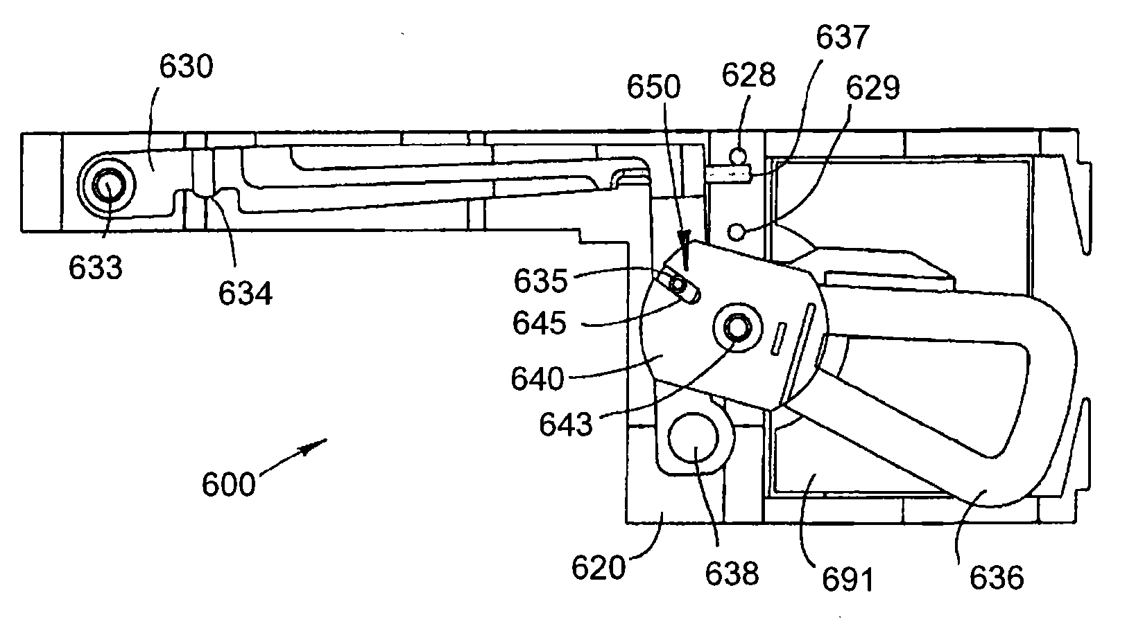
更准确地说,图5所示的操作机构系统600包括一操作杆630和线圈-磁铁传动装置,该操作机构包括一操作件640,具有一线圈636设置在磁铁641(仅示出一个)之间,所述磁铁安装在支承结构620上。系统适合于与泵一起使用,该泵包括一泵构件所述泵构件可通过驱动例如与图1相对应的操作杆移动,为此操作杆包括接头部分634(对应于接头销534),该接头部分适合于啮合待移动的构件。第一枢轴接头取第一轴向轴承633的形式,该第一轴向轴承633在操作杆和支承结构之间形式,第二枢轴接头取第二轴向轴承643的形式,该第二轴向轴承643在操作件和支承结构之间形成。操作杆和操作件通过安装在第一和第二枢轴接头之间的连轴器连接650相互连接,从而操作件朝第一方向的旋转使操作机构朝相反的第二方向旋转。More specifically, the operating mechanism system 600 shown in FIG. 5 includes an operating
这种安排原则上与两齿轮相互啮合相对应。如果两个齿轮(或构件)相同,则它们相互平衡,然而,如果它们不同,但只要它们相互啮合,则具有较低惯性动量的“较小”构件将在某种程度上补偿具有较高惯性动量的“较大”构件,这导致杠杆操作机构系统与例如图4中所示的系统相比,对外部线性或旋转的影响具有较低的敏感度,在上述图4所示的系统中一长的单个操作臂对应于第一枢轴节枢转,并具有一线圈安装在与操作机构相同的位置处。为了增加操作杆的惯性动量,设有一重量638,例如金属元件,该金属元件附接到聚合物操作杆上。This arrangement corresponds in principle to the meshing of the two gears. If the two gears (or members) are the same, they balance each other out, however, if they are different, but as long as they mesh with each other, the "smaller" member with the lower moment of inertia will somewhat compensate for having the higher inertia A "larger" component of momentum, which results in a lever-operator system that is less sensitive to external linear or rotational influences than, for example, the system shown in Figure 4, where a A long single operating arm pivots corresponding to the first pivot joint and has a coil mounted at the same location as the operating mechanism. In order to increase the moment of inertia of the joystick, a weight 638 is provided, such as a metal element, which is attached to the polymer joystick.
在所示的实施例中,操作杆在第一位置(见图5)和第二位置(见图6)之间移动,组件包括第一和第二止动机构628,629,该第一和第二止动机构628,629分别适合于将操作杆的运动限制在第一和第二位置中。在所示的实施例中,操作杆包括一接触件637,该接触件637接合也用作接触件的止动件,这样能检测操作机构运动(见上面)。在使用的情况下,操作机构系统连接到泵上(如在图7中那样),该泵包括一泵构件,所述泵构件可通过接头点驱动操作杆移动,泵包括一挠性构件,该挠性构件取泵隔膜的形式,当泵构件在其第一和第二位置之间移动时,泵隔膜被泵构件拉伸。In the illustrated embodiment, the lever moves between a first position (see FIG. 5) and a second position (see FIG. 6), and the assembly includes first and second stop mechanisms 628, 629, the first and The second stop mechanisms 628, 629 are adapted to limit movement of the operating lever in the first and second positions, respectively. In the embodiment shown, the operating lever includes a contact 637 which engages a stop which also acts as a contact, thus enabling detection of the operating mechanism movement (see above). In the case of use, the operating mechanism system is connected to the pump (as in Figure 7), the pump includes a pump member that can drive the operating rod to move through the joint point, the pump includes a flexible member, the The flexible member is in the form of a pump diaphragm which is stretched by the pump member as the pump member moves between its first and second positions.
当连接到泵上时,泵构件(例如活塞)具有第一位置和第二位置,该第一位置与操作杆的第一位置和泵的第一静止状况相对应,而第二位置与操作杆的第二位置和泵的第二驱动状况相对应,其中当泵隔膜对应于泵冲程被拉伸时,泵构件通过泵隔膜在第一位置中施加第一力在操作杆上,和在第二位置中施加第二力在操作杆上。When connected to a pump, a pump member (such as a piston) has a first position corresponding to the first position of the operating rod and a first resting condition of the pump, and a second position corresponding to the first position of the operating rod The second position corresponds to a second drive condition of the pump, wherein the pump member exerts a first force on the operating rod in the first position through the pump diaphragm when the pump diaphragm is stretched corresponding to the pump stroke, and in the second position to apply a second force on the joystick.
所示的传动装置系统的联接节不似两个传统的齿轮之间的齿啮合,而是取销钉635和导槽(或“长孔”)645的形式,该销钉635安装在操作杆上,而导槽645在操作件中具有两个对置的壁,销钉安装成在导槽645中滑动,这样使销钉在导槽中的位置能确定操作杆和操作机构之间的实际齿轮传动比。根据导槽的取向和配置,能将系统设计成随着操作件并因此操作杆的旋转位置的变化而在操作件,和操作杆之间具有不同的齿轮传动比。这种效应是由于下述原因:当操作件旋转时,“实际的”力朝一个方向被传送到销钉上,该方向由垂直于壁部分作用在销钉上限定,然而,提供传送到操作杆上的“旋转的”力的转矩是在垂直于穿过第一枢轴节和销钉的连线的方向上起作用的力的一部分。正如在图5出可以看出的,在第一位置中的旋转力小于实际力,而在如图6所示的第二位置中,旋转力基本上相当于实际力。The coupling of the transmission system shown does not resemble a tooth mesh between two conventional gears, but instead takes the form of a pin 635 mounted on the operating lever and a guide slot (or "slot") 645, Whereas the channel 645 has two opposing walls in the operating member, the pin is mounted to slide in the channel 645 such that the position of the pin in the channel determines the actual gear ratio between the operating lever and the operating mechanism. Depending on the orientation and configuration of the guide slots, the system can be designed to have different gear ratios between the operating member, and thus the operating rod, as the rotational position of the operating member, and thus the operating rod, varies. This effect is due to the following reason: When the operating member is rotated, the "real" force is transmitted to the pin in a direction defined by the force acting on the pin perpendicular to the wall portion, however, providing the transmission to the operating rod The torque of the "rotational" force is the portion of the force acting in a direction perpendicular to the line passing through the first pivot joint and the pin. As can be seen in FIG. 5 , the rotational force in the first position is less than the actual force, whereas in the second position shown in FIG. 6 the rotational force substantially corresponds to the actual force.
如从上述可以得出,当包括如图5所示的操作机构系统的泵组件受到加速作用且加速作用产生线圈操作件的旋转运动时,则来自操作机构作用在操作杆上的力在第一位置中最小,这相当于“高”齿轮传动比。因为该位置相当于泵的静止位置,所以这也意味着对泵被泵组件的角加速作用驱动的敏感度减小。实际上,这仅与系统是否不完美地相对于线性加速度或角加速度二者平衡有关,然而,为得到这种系统实际上也许不可能。关于所希望的通过线圈操作机构的旋转驱动隔膜泵,在开始驱动时作用在泵构件上的较低驱动力不影响泵组件的功能性,因为起初泵阻力像泵隔膜刚开始伸展时一样低。随着泵阻力由于泵隔膜的进一步伸展而增加,则操作机构线圈和操作杆之间的齿轮传动比也从“高”改变到“低”。As can be drawn from the above, when the pump assembly including the operating mechanism system as shown in FIG. The smallest of the positions, which corresponds to a "high" gear ratio. Since this position corresponds to the rest position of the pump, this also means a reduced sensitivity to the pump being driven by angular acceleration effects of the pump assembly. In practice, this is only a matter of whether the system is not perfectly balanced with respect to both linear or angular acceleration, however, it may not be practical to obtain such a system. With regard to the desired rotationally driven diaphragm pump by the coil operator, the lower driving force acting on the pump member at the start of the drive does not affect the functionality of the pump assembly because initially the pump resistance is as low as when the pump diaphragm first begins to stretch. As the pump resistance increases due to further stretching of the pump diaphragm, the gear ratio between the operating mechanism coil and the operating rod also changes from "high" to "low".
如从上面可以得出,通过改变例如两个构件的枢轴节、质量、质量的重心、槽的位置和配置,能相对于效率和对外力影响的敏感度将系统优化在所需的参数框架内。As can be derived from the above, by varying for example the pivot joints of the two members, the mass, the center of gravity of the mass, the location and configuration of the slots, the system can be optimized in a desired parameter framework with respect to efficiency and sensitivity to external force influences Inside.
图7示出一种泵装置,同时外壳的上面部分被除去。泵装置505包括容器760、具有泵300及线圈操作机构581的泵组件、和用于控制其的控制器机构580。泵组件包括出口322和开口323,该出口322用于连接到经皮进入装置上,而开口323能驱动安装在泵组件中的流体连接器,并因而将泵组件与容器连接。容器760取预充装的柔软而可折叠的囊的形式,该囊包括一注液针可穿过的中隔,所述中隔适合于安装成与泵组件流体连通。所示的泵组件包括图2所示类型的机械驱动式隔膜泵,然而,不同类型的泵也可以使用。Figure 7 shows a pump device with the upper part of the housing removed. The
控制机构包括一微处理器连接于其上的PCB(印刷电路板)或柔性印刷电路,该微处理器用于控制其中包括泵驱动、与接线装置(见下面)上相应接触操作机构配合的接触588、589、操作机构中的位置检测器、用于产生音响信号和/或触觉信号的信号发生机构585、显示器(如果设置的话)、存储器、能使泵装置与无线遥控装置通信的发射机和接收机。能源586提供能量。The control mechanism consists of a PCB (printed circuit board) or flexible printed circuit to which is attached a microprocessor for controlling the
图8示出一种接线装置1010的实施例,该接线装置1010在它的侧面具有一泵装置1050,而图9示出泵装置完全但可松开式连接。更准确地说,图8示出医疗装置1000的实施例,该医疗装置1000包括在申请人的共同待批的申请WO 2006/120253中所公开的类型的插管装置1010,且泵装置1050可安装于其上。在所示的实施例中,插管装置包括一外壳1015,该外壳1015具有一轴,泵装置的一部分1051插入所述轴中。轴具有一盖部分1011,该盖部分1011具有开口1012,盖的自由端形成一具有较低突起(未示出)的挠性闭锁件1013,所述闭锁件1013适合于接合泵装置中的相应凹入部分1052,因为当泵装置插入插管装置的轴中时,提供一种速动连接。另外可以看到一通风口1054。外壳1015设有一对对置的支脚1018,且用下面的用作安装面的胶粘剂表面1020安装在挠性薄板件1019的顶部上,所述薄板件1019包括用于插管1017的开口1016。Fig. 8 shows an embodiment of a
如所显示的,从插管装置的外壳将插管以一倾斜的角度延伸,该插管这样安装,以便它穿过皮肤表面的插入部位可以例如在刚插入之后检查(在图中整个插管可以看到)。在所示的实施例中,盖中的开口提供改善的插入部位的不可检查性。当泵装置连接到插管装置上时,它完全盖住并保护插管和插入部位免受外部例如水、污物和机械力的影响(见图9),然而,因为泵装置是可拆卸式连接到插管装置上,所以可以将泵装置松开(通过升起闭锁件)并全部或部分地从插管装置中抽出,这样能在任何所希望的时间点处检查插入部位,通过这种安排,提供一种药物输送装置,该药物输送装置具有一经皮装置,例如软插管,如所示,该软插管在正常使用期间很好地受保护,然而,通过全部或部分地拆卸泵装置可以按希望对其检查。实际上,规定的装置可以这样形成,以便在连接泵期间,至少在某种程度上,插入部位也可以例如通过相应的开口或透明区进行检查,然而,连接的泵在使用期间提供高度保护,而与为在连接泵期间检查插入部位全部或部分地被闭合无关。在所示的实施例中,使用倾斜的插管,然而,在可供选择的实施例中,注液针或插管可以相对于安装表面垂直地插入。As shown, the cannula extends at an oblique angle from the housing of the intubation device, and the cannula is installed so that its insertion site through the skin surface can be inspected, for example, immediately after insertion (in the figure the entire cannula can be seen). In the illustrated embodiment, the opening in the cover provides improved uninspectability of the insertion site. When the pump unit is attached to the cannula unit, it completely covers and protects the cannula and insertion site from external influences such as water, dirt and mechanical forces (see Figure 9), however, since the pump unit is detachable Connected to the intubation device so that the pump unit can be released (by lifting the latch) and fully or partially withdrawn from the intubation device, allowing the insertion site to be inspected at any desired point in time, through this arrangement, to provide a drug delivery device having a percutaneous device, such as a soft cannula, which, as shown, is well protected during normal use, however, by dismantling the pump in whole or in part The device can check it as desired. In fact, the prescribed means can be formed so that during the connection of the pump, at least to some extent, the insertion site can also be inspected, for example through corresponding openings or transparent areas, however, the connected pump provides a high degree of protection during use, Regardless of whether the insertion site is fully or partially closed for checking during connection of the pump. In the illustrated embodiment, an angled cannula is used, however, in alternative embodiments, the infusion needle or cannula may be inserted perpendicularly relative to the mounting surface.
参见图8和9,已说明了包括泵装置和接线装置的组合式泵系统,然而,系统也可以作为整体装置提供。Referring to Figures 8 and 9, a combined pump system comprising a pump unit and a wiring unit has been described, however, the system may also be provided as a unitary unit.
实例:Example:
设计一种两部分臂和线圈操作机构系统并进行理论分析,以便确定当系统经受外力如线性加速度和角加速度时的机械响应,见图10A-10C。A two-part arm and coil operator system was designed and theoretically analyzed to determine the mechanical response when the system is subjected to external forces such as linear and angular acceleration, see Figures 10A-10C.
为了简化问题,作出下列近似表示方法:泵壳、臂、和线圈系统是刚性的;臂和线圈紧密座落在它们的轴上,以便作用可以忽略不计;线圈连接销紧密座落在臂长孔中,以便作用可以忽略不计;虚构的离心力和复合向心力忽略不计;动态方程在静止位置周围线性化。In order to simplify the problem, the following approximate representations are made: the pump casing, arm, and coil system are rigid; the arm and coil are tightly seated on their axes so that the effect can be ignored; the coil connection pin is tightly seated in the long hole of the arm , so that the action is negligible; the imaginary centrifugal and compound centripetal forces are negligible; the dynamic equations are linearized around the rest position.
分析表明,原则上能设计一种系统,该系统在静止位置中对线性加速度和角加速度二者不敏感:为了使系统相对于线性加速度平衡,臂和线圈的质量位置的重心应按下式对准:The analysis shows that, in principle, it is possible to design a system which is insensitive to both linear and angular accelerations in the rest position: In order to balance the system with respect to linear accelerations, the center of gravity of the mass positions of the arms and coils should be given by allow:
M1(C1-A1)=M2G(C2-A2),G=-dθ2/dθ1 M 1 (C 1 -A 1 )=M 2 G(C 2 -A 2 ), G=-dθ 2 /dθ 1
式中下标“1”代表臂和“2”代表线圈,A代表旋转点,C代表质量的中心,M代表质量,和G代表齿轮传动,同时θ代表与水平轴线的偏转角。Where the subscript "1" represents the arm and "2" represents the coil, A represents the point of rotation, C represents the center of mass, M represents the mass, and G represents the gear transmission, while θ represents the deflection angle from the horizontal axis.
另外,为了使系统相对于角加速度平衡,臂和线圈的惯性矩应按下式平衡:Also, in order to balance the system with respect to the angular acceleration, the moment of inertia of the arm and the coil should be balanced as follows:
I1=G(I2+M2L2L0cos(θ2+δ2-δ0))I 1 =G(I 2 +M 2 L 2 L 0 cos(θ 2 +δ 2 -δ 0 ))
式中I代表A周围的惯性矩,L2代表距离|A2C2|,L0代表距离|A1A2|,δ2代表线圈轴线与A2C2之间的角度,及δ0代表线圈轴线与A1A2之间的角度。In the formula, I represents the moment of inertia around A, L 2 represents the distance |A 2 C 2 |, L 0 represents the distance |A 1 A 2 |, δ 2 represents the angle between the coil axis and A 2 C 2 , and δ 0 Represents the angle between the coil axis and A 1 A 2 .
实际上,上述分析也可以用来优化一种系统,而不用为在静止位置对线性加速度和角加速度完全不敏感的系统努力。In fact, the above analysis can also be used to optimize a system without having to work on a system that is completely insensitive to linear and angular acceleration at rest.
在上述示例性实施例的说明中,已经说明了对不同部件提供所述功能性的不同结构,在一定程度上本发明的思想对该领域的专业读者来说显而易见。不同结构的详细构造和配置可以认为是由该领域的技术人员沿着本说明所陈述的路线实施的正常设计操作的对象。例如,所公开的实施例的各个部件可以用适合于医用和大量生产的材料例如合适的聚合物材料制造,且装配利用低成本的技术如粘结法、粘接法、胶粘剂和机械互连。In the above description of the exemplary embodiments, different structures providing the described functionality for different components have been described, to a certain extent the idea of the present invention will be apparent to the professional readers in the field. The detailed construction and arrangement of the different structures can be considered the object of normal design operations performed by those skilled in the art along the lines set forth in this specification. For example, the various components of the disclosed embodiments can be fabricated from materials suitable for medical use and mass production, such as suitable polymeric materials, and assembled using low-cost techniques such as bonding, bonding, adhesives, and mechanical interconnections.
Claims (13)
Applications Claiming Priority (2)
| Application Number | Priority Date | Filing Date | Title |
|---|---|---|---|
| EP07103590.1 | 2007-03-06 | ||
| EP07103590 | 2007-03-06 |
Publications (1)
| Publication Number | Publication Date |
|---|---|
| CN101641123A true CN101641123A (en) | 2010-02-03 |
Family
ID=39288292
Family Applications (1)
| Application Number | Title | Priority Date | Filing Date |
|---|---|---|---|
| CN200880007387A Withdrawn CN101641123A (en) | 2007-03-06 | 2008-03-06 | Pump assembly comprising actuator system |
Country Status (5)
| Country | Link |
|---|---|
| US (1) | US20100063448A1 (en) |
| EP (1) | EP2114492A1 (en) |
| JP (1) | JP2010520409A (en) |
| CN (1) | CN101641123A (en) |
| WO (1) | WO2008107467A1 (en) |
Cited By (1)
| Publication number | Priority date | Publication date | Assignee | Title |
|---|---|---|---|---|
| CN106456887A (en) * | 2014-03-28 | 2017-02-22 | 再生产系统有限公司 | Compact mechanical pump |
Families Citing this family (5)
| Publication number | Priority date | Publication date | Assignee | Title |
|---|---|---|---|---|
| US8034026B2 (en) * | 2001-05-18 | 2011-10-11 | Deka Products Limited Partnership | Infusion pump assembly |
| US10583241B2 (en) * | 2013-05-03 | 2020-03-10 | Becton, Dickinson And Company | Drug delivery device |
| EP2832390A1 (en) * | 2013-07-30 | 2015-02-04 | Sensile Pat AG | Drug delivery device with needle actuation mechanism |
| EP3684445B1 (en) | 2017-09-20 | 2023-08-23 | Fresenius Vial SAS | Medical device having a detachable cover element |
| KR102378501B1 (en) * | 2019-12-17 | 2022-03-25 | 이오플로우(주) | Drug injection device, driving time symmetry method and recording medium using driving time symmetry algorithm |
Family Cites Families (101)
| Publication number | Priority date | Publication date | Assignee | Title |
|---|---|---|---|---|
| US6241704B1 (en) * | 1901-11-22 | 2001-06-05 | Sims Deltec, Inc. | Drug pump systems and methods |
| US2605765A (en) * | 1947-06-05 | 1952-08-05 | Kollsman Paul | Automatic syringe |
| US2980032A (en) * | 1959-02-27 | 1961-04-18 | Brown Engine Products Inc | Fuel pump |
| US4016879A (en) * | 1973-08-22 | 1977-04-12 | Dynasciences Corporation | Multi-mode cannulating apparatus |
| US4245634A (en) * | 1975-01-22 | 1981-01-20 | Hospital For Sick Children | Artificial beta cell |
| DE2513467C3 (en) * | 1975-03-26 | 1979-10-31 | Siemens Ag, 1000 Berlin Und 8000 Muenchen | Device for infusing liquids into the human or animal body |
| US4137020A (en) * | 1976-12-26 | 1979-01-30 | Nippondenso Co., Ltd. | Diaphragm type air pump |
| US4262824A (en) * | 1978-02-17 | 1981-04-21 | Baxter Travenol Laboratories, Inc. | Low-current E-frame electronic magnet with a permanent magnet armature for an I. V. valving controller |
| DE2820281A1 (en) * | 1978-05-10 | 1979-11-15 | Fresenius Chem Pharm Ind | HOSE PUMP WITH HIGH DOSING ACCURACY |
| DE2929813A1 (en) * | 1979-07-23 | 1981-01-29 | Hoelzle & Chelius Kg | METHOD FOR DISMOUNTING FLOWABLE MEDIA AND DEVICE FOR IMPLEMENTING THE METHOD |
| US4340048A (en) * | 1981-03-28 | 1982-07-20 | Alza Corporation | Self-driven hypodermic injector |
| US4399824A (en) * | 1981-10-05 | 1983-08-23 | Air-Shields, Inc. | Apparatus for detecting probe dislodgement |
| US4378015A (en) * | 1981-12-21 | 1983-03-29 | Wardlaw Stephen C | Automatic injecting syringe |
| US4529401A (en) * | 1982-01-11 | 1985-07-16 | Cardiac Pacemakers, Inc. | Ambulatory infusion pump having programmable parameters |
| US4753651A (en) * | 1982-08-30 | 1988-06-28 | Alza Corporation | Self-driven pump |
| US4519792A (en) * | 1982-12-06 | 1985-05-28 | Abbott Laboratories | Infusion pump system |
| CA1221596A (en) * | 1984-03-09 | 1987-05-12 | David Evans | Surgical needle |
| US4657490A (en) * | 1985-03-27 | 1987-04-14 | Quest Medical, Inc. | Infusion pump with disposable cassette |
| US4755173A (en) * | 1986-02-25 | 1988-07-05 | Pacesetter Infusion, Ltd. | Soft cannula subcutaneous injection set |
| US5211201A (en) * | 1986-03-04 | 1993-05-18 | Deka Products Limited Partnership | Intravenous fluid delivery system with air elimination |
| US4734092A (en) * | 1987-02-18 | 1988-03-29 | Ivac Corporation | Ambulatory drug delivery device |
| US4994078A (en) * | 1988-02-17 | 1991-02-19 | Jarvik Robert K | Intraventricular artificial hearts and methods of their surgical implantation and use |
| US4894054A (en) * | 1988-06-20 | 1990-01-16 | Miskinyar Shir A | Preloaded automatic disposable syringe |
| US4928528A (en) * | 1988-07-25 | 1990-05-29 | Cordis Corporation | Arterial/venous simulator |
| US5008110A (en) * | 1988-11-10 | 1991-04-16 | The Procter & Gamble Company | Storage-stable transdermal patch |
| AU633104B2 (en) * | 1989-06-14 | 1993-01-21 | Debiotech S.A. | Improved micro-pump |
| US5122116A (en) * | 1990-04-24 | 1992-06-16 | Science Incorporated | Closed drug delivery system |
| US5527288A (en) * | 1990-12-13 | 1996-06-18 | Elan Medical Technologies Limited | Intradermal drug delivery device and method for intradermal delivery of drugs |
| US5122201A (en) * | 1991-11-19 | 1992-06-16 | International Business Machines Corporation | Water-soluble solder flux |
| US5223433A (en) * | 1991-12-13 | 1993-06-29 | Diametrics Medical Inc. | Temperature stabilized fluid calibration system |
| DE4336336A1 (en) * | 1992-11-23 | 1994-05-26 | Lang Volker | Cassette infusion system |
| US5336052A (en) * | 1993-04-28 | 1994-08-09 | Abel Pumpen Gmbh & Co. Kg | Viscous material pump |
| US5391950A (en) * | 1993-06-24 | 1995-02-21 | Unisys Corporation | Circuit to eliminate signal chatter in the output of a fiber-optic receiver |
| US5485917A (en) * | 1993-12-06 | 1996-01-23 | Ethicon-Endo-Surgery | Quick release package for surgical instrument |
| US5390671A (en) * | 1994-03-15 | 1995-02-21 | Minimed Inc. | Transcutaneous sensor insertion set |
| US5514095A (en) * | 1994-04-04 | 1996-05-07 | Haemonetics Corporation | Apparatus for heating, filtering and eliminating gas from biological fluids |
| US5482473A (en) * | 1994-05-09 | 1996-01-09 | Minimed Inc. | Flex circuit connector |
| US5582591A (en) * | 1994-09-02 | 1996-12-10 | Delab | Delivery of solid drug compositions |
| US5494415A (en) * | 1994-09-12 | 1996-02-27 | Morita; Yoshimitsu | Magnetically-driven pump |
| CA2159052C (en) * | 1994-10-28 | 2007-03-06 | Rainer Alex | Injection device |
| US5647853A (en) * | 1995-03-03 | 1997-07-15 | Minimed Inc. | Rapid response occlusion detector for a medication infusion pump |
| US5776103A (en) * | 1995-10-11 | 1998-07-07 | Science Incorporated | Fluid delivery device with bolus injection site |
| ZA9610374B (en) * | 1995-12-11 | 1997-06-23 | Elan Med Tech | Cartridge-based drug delivery device |
| US5860952A (en) * | 1996-01-11 | 1999-01-19 | C. R. Bard, Inc. | Corporeal access tube assembly and method |
| US5720391A (en) * | 1996-03-29 | 1998-02-24 | St. Jude Medical, Inc. | Packaging and holder for heart valve prosthesis |
| US5776109A (en) * | 1996-08-23 | 1998-07-07 | Urrutia; Hector | Drip chamber for intravenous fluid delivery system |
| US5928194A (en) * | 1997-04-07 | 1999-07-27 | Maget; Henri J. R. | Self-contained liquid microdispenser |
| US6530900B1 (en) * | 1997-05-06 | 2003-03-11 | Elan Pharma International Limited | Drug delivery device |
| US5913856A (en) * | 1997-05-19 | 1999-06-22 | Irvine Biomedical, Inc. | Catheter system having a porous shaft and fluid irrigation capabilities |
| US6558351B1 (en) * | 1999-06-03 | 2003-05-06 | Medtronic Minimed, Inc. | Closed loop system for controlling insulin infusion |
| US6716192B1 (en) * | 1997-09-30 | 2004-04-06 | Charles F. Schroeder | Medical needle having a visibly marked tip |
| US6045534A (en) * | 1997-10-27 | 2000-04-04 | Sarcos, Inc. | Disposable fluid injection module |
| WO1999029365A1 (en) * | 1997-12-11 | 1999-06-17 | Alza Corporation | Device for enhancing transdermal agent flux |
| US5957895A (en) * | 1998-02-20 | 1999-09-28 | Becton Dickinson And Company | Low-profile automatic injection device with self-emptying reservoir |
| US6554798B1 (en) * | 1998-08-18 | 2003-04-29 | Medtronic Minimed, Inc. | External infusion device with remote programming, bolus estimator and/or vibration alarm capabilities |
| US6358731B1 (en) * | 1999-10-20 | 2002-03-19 | Wei K. Hsu | Sterilizable cultivation system with separately attachable microfiltration membrane |
| EP1124600B1 (en) * | 1998-10-29 | 2005-02-23 | Medtronic MiniMed, Inc. | Compact pump drive system |
| JP2002529204A (en) * | 1998-11-13 | 2002-09-10 | エラン・フアルマ・インターナシヨナル・リミテツド | System and method for delivering chemicals |
| DE19908438C2 (en) * | 1999-02-26 | 2003-05-15 | Cochlear Ltd | Device and method for supporting the positioning of an external transmitting part with respect to an implantable receiving part of a charging system of an implantable medical device |
| US6554791B1 (en) * | 1999-09-29 | 2003-04-29 | Smisson-Cartledge Biomedical, Llc | Rapid infusion system |
| US6427088B1 (en) * | 2000-01-21 | 2002-07-30 | Medtronic Minimed, Inc. | Ambulatory medical apparatus and method using telemetry system with predefined reception listening periods |
| JP2001288309A (en) * | 2000-01-26 | 2001-10-16 | Tokuyama Corp | Flame retardant polyolefin composition |
| US6461329B1 (en) * | 2000-03-13 | 2002-10-08 | Medtronic Minimed, Inc. | Infusion site leak detection system and method of using the same |
| DE10029453C2 (en) * | 2000-06-21 | 2002-06-13 | Roche Diagnostics Gmbh | Pump for very low flow rates |
| US7530964B2 (en) * | 2000-06-30 | 2009-05-12 | Elan Pharma International Limited | Needle device and method thereof |
| US6589229B1 (en) * | 2000-07-31 | 2003-07-08 | Becton, Dickinson And Company | Wearable, self-contained drug infusion device |
| US6669669B2 (en) * | 2001-10-12 | 2003-12-30 | Insulet Corporation | Laminated patient infusion device |
| WO2002020073A2 (en) * | 2000-09-08 | 2002-03-14 | Insulet Corporation | Devices, systems and methods for patient infusion |
| AU9658801A (en) * | 2000-10-04 | 2002-04-15 | Insulet Corp | Data collection assembly for patient infusion system |
| CA2327012C (en) * | 2000-11-28 | 2006-09-26 | Duncan Wade | Diaphragm for a diaphragm pump |
| DE10063242C2 (en) * | 2000-12-19 | 2003-02-20 | Siemens Ag | Communication terminal with antenna |
| US7052483B2 (en) * | 2000-12-19 | 2006-05-30 | Animas Corporation | Transcutaneous inserter for low-profile infusion sets |
| WO2002068015A2 (en) * | 2001-02-22 | 2002-09-06 | Insulet Corporation | Modular infusion device and method |
| US6854620B2 (en) * | 2001-04-13 | 2005-02-15 | Nipro Diabetes, Systems, Inc. | Drive system for an infusion pump |
| US6550493B2 (en) * | 2001-06-13 | 2003-04-22 | Baxter International Inc. | Vacuum demand valve |
| US20030088238A1 (en) * | 2001-09-26 | 2003-05-08 | Poulsen Jens Ulrik | Modular drug delivery system |
| US6830562B2 (en) * | 2001-09-27 | 2004-12-14 | Unomedical A/S | Injector device for placing a subcutaneous infusion set |
| US6613015B2 (en) * | 2001-10-04 | 2003-09-02 | Deltec, Inc. | Right angle safety needle |
| US8066678B2 (en) * | 2001-12-17 | 2011-11-29 | Bard Access Systems, Inc. | Safety needle with collapsible sheath |
| US6703252B2 (en) * | 2002-01-31 | 2004-03-09 | Hewlett-Packard Development Company, L.P. | Method of manufacturing an emitter |
| US6878136B2 (en) * | 2002-02-28 | 2005-04-12 | Medical Product Specialists | Huber needle with anti-rebound safety mechanism |
| US6692457B2 (en) * | 2002-03-01 | 2004-02-17 | Insulet Corporation | Flow condition sensor assembly for patient infusion device |
| EP1517725B1 (en) * | 2002-06-28 | 2015-09-09 | Boston Scientific Neuromodulation Corporation | Microstimulator having self-contained power source and bi-directional telemetry system |
| US20040116905A1 (en) * | 2002-09-09 | 2004-06-17 | Pedersen Per Elgard | Flow restrictor with safety feature |
| EP1403519A1 (en) * | 2002-09-27 | 2004-03-31 | Novo Nordisk A/S | Membrane pump with stretchable pump membrane |
| DE10255817A1 (en) * | 2002-11-29 | 2004-06-17 | Disetronic Licensing Ag | Catheter head with lockable sealing element |
| US7070580B2 (en) * | 2003-04-01 | 2006-07-04 | Unomedical A/S | Infusion device and an adhesive sheet material and a release liner |
| WO2004093648A2 (en) * | 2003-04-18 | 2004-11-04 | Insulet Corporation | User interface for infusion pump remote controller and method of using the same |
| EP1624913B1 (en) * | 2003-05-08 | 2010-07-21 | Novo Nordisk A/S | Skin mountable injection device with a detachable needle insertion actuation portion |
| ATE392223T1 (en) * | 2003-05-08 | 2008-05-15 | Novo Nordisk As | INTERNAL NEEDLE INTRODUCER |
| US7097690B2 (en) * | 2003-10-10 | 2006-08-29 | Scimed Life Systems, Inc. | Apparatus and method for removing gasses from a liquid |
| KR20060099520A (en) * | 2003-10-21 | 2006-09-19 | 노보 노르디스크 에이/에스 | Medical Skin Mounting Device |
| US7699808B2 (en) * | 2003-11-10 | 2010-04-20 | Smiths Medical Asd, Inc. | Subcutaneous infusion device and method |
| US7309326B2 (en) * | 2003-11-18 | 2007-12-18 | Icu Medical, Inc. | Infusion set |
| ZA200608085B (en) * | 2004-03-30 | 2008-06-25 | Novo Nordisk As | Actuator system comprising detection means |
| WO2005094920A1 (en) * | 2004-03-30 | 2005-10-13 | Novo Nordisk A/S | Actuator system comprising lever mechanism |
| US7289855B2 (en) * | 2004-06-09 | 2007-10-30 | Medtronic, Inc. | Implantable medical device package antenna |
| US7265676B2 (en) * | 2004-07-20 | 2007-09-04 | Medtronic, Inc. | Alert system and method for an implantable medical device |
| DK1881820T3 (en) * | 2005-05-17 | 2020-08-24 | Hoffmann La Roche | Disposable dispenser for patient infusion |
| US7534226B2 (en) * | 2005-09-26 | 2009-05-19 | M2 Group Holdings, Inc. | Dispensing fluid from an infusion pump system |
| US20090163874A1 (en) * | 2006-04-26 | 2009-06-25 | Novo Nordisk A/S | Skin-Mountable Device in Packaging Comprising Coated Seal Member |
-
2008
- 2008-03-06 CN CN200880007387A patent/CN101641123A/en not_active Withdrawn
- 2008-03-06 EP EP08717455A patent/EP2114492A1/en not_active Withdrawn
- 2008-03-06 US US12/529,882 patent/US20100063448A1/en not_active Abandoned
- 2008-03-06 WO PCT/EP2008/052707 patent/WO2008107467A1/en not_active Ceased
- 2008-03-06 JP JP2009552206A patent/JP2010520409A/en not_active Withdrawn
Cited By (2)
| Publication number | Priority date | Publication date | Assignee | Title |
|---|---|---|---|---|
| CN106456887A (en) * | 2014-03-28 | 2017-02-22 | 再生产系统有限公司 | Compact mechanical pump |
| CN106456887B (en) * | 2014-03-28 | 2019-09-03 | 再生产系统有限公司 | compact mechanical pump |
Also Published As
| Publication number | Publication date |
|---|---|
| JP2010520409A (en) | 2010-06-10 |
| WO2008107467A1 (en) | 2008-09-12 |
| US20100063448A1 (en) | 2010-03-11 |
| EP2114492A1 (en) | 2009-11-11 |
Similar Documents
| Publication | Publication Date | Title |
|---|---|---|
| JP6802399B2 (en) | Separation piston type metering pump | |
| US20230256160A1 (en) | Systems, apparatuses and methods for fluid infusion into a body | |
| CN100586495C (en) | Actuator system comprising lever mechanism | |
| CN1938061B (en) | Actuator system comprising detection means | |
| CN204972511U (en) | Micropump of medicine is carried through infusion | |
| CN101641123A (en) | Pump assembly comprising actuator system | |
| EP2698178B1 (en) | Pump engine with metering system for dispensing liquid medication | |
| EP2050476B1 (en) | Implantable infusion device with multiple controllable fluid outlets | |
| EP2140892B1 (en) | Volumetric micropump | |
| US20080167641A1 (en) | Medical Device Adapted To Detect Disengagement Of A Transcutaneous Device | |
| CN102498292B (en) | Fluid delivery system comprising a fluid pumping device and a drive system | |
| US20110021993A1 (en) | Miniature disposable or partially reusable dosing pump | |
| CN113382757B (en) | Devices and systems for delivering medical fluids and related delivery methods | |
| US20090287180A1 (en) | Disposable pump reservoir and related methods | |
| CN101611227A (en) | Positive displacement pump | |
| CN1642589A (en) | Ambulatory infusion membrane pump | |
| KR20140110496A (en) | Drug infusion pump | |
| CN101522236A (en) | Micropump-operated drug dosing system | |
| US11041491B2 (en) | Micro dosage peristaltic pump for micro dosage of fluid | |
| US8277196B2 (en) | Adaptive accuracy for enteral feeding pump | |
| CN106640579B (en) | A kind of accurate adjusting metering pump | |
| JP2014200363A (en) | Medicine solution administration device, and medicine solution administration method | |
| KR100597601B1 (en) | Biological liquid injection device | |
| JP2024502481A (en) | An infusion set with the ability to control the amount of injectable drug injected into one of the extremities, as well as a system for detecting and controlling the drip rate of the infusion device | |
| HK1139085B (en) | Volumetric micropump |
Legal Events
| Date | Code | Title | Description |
|---|---|---|---|
| C06 | Publication | ||
| PB01 | Publication | ||
| C10 | Entry into substantive examination | ||
| SE01 | Entry into force of request for substantive examination | ||
| C04 | Withdrawal of patent application after publication (patent law 2001) | ||
| WW01 | Invention patent application withdrawn after publication |
Open date: 20100203 |