CN101630623B - Inspection apparatus by charged particle beam and method for manufacturing device using inspection apparatus - Google Patents
Inspection apparatus by charged particle beam and method for manufacturing device using inspection apparatus Download PDFInfo
- Publication number
- CN101630623B CN101630623B CN2009101641115A CN200910164111A CN101630623B CN 101630623 B CN101630623 B CN 101630623B CN 2009101641115 A CN2009101641115 A CN 2009101641115A CN 200910164111 A CN200910164111 A CN 200910164111A CN 101630623 B CN101630623 B CN 101630623B
- Authority
- CN
- China
- Prior art keywords
- wafer
- electrons
- sample
- electron
- electron beam
- Prior art date
- Legal status (The legal status is an assumption and is not a legal conclusion. Google has not performed a legal analysis and makes no representation as to the accuracy of the status listed.)
- Expired - Lifetime
Links
Images


Landscapes
- Testing Or Measuring Of Semiconductors Or The Like (AREA)
- Analysing Materials By The Use Of Radiation (AREA)
Abstract
A system for further enhancing speed, i.e. improving throughput in a SEM-type inspection apparatus is provided. An inspection apparatus for inspecting a surface of a substrate produces a crossover from electrons emitted from an electron beam source 25.1 , then forms an image under a desired magnification in the direction of a sample W to produce a crossover. When the crossover is passed, electrons as noises are removed from the crossover with an aperture, an adjustment is made so that the crossover becomes a parallel electron beam to irradiate the substrate in a desired sectional form. The electron beam is produced such that the unevenness of illuminance is 10% or less. Electrons emitted from the sample W are detected by a detector 25.11.
Description
The invention is a divisional application of the following applications, and the original application information is as follows:
application date: 26/04/2004
Application No.: 200480019519.9
The invention name is as follows: charged particle beam inspection apparatus and device manufacturing method using the same
Technical Field
The present invention relates to an inspection apparatus for inspecting defects of a pattern formed on a surface of an inspection object by an electron beam, and more particularly, to an inspection apparatus for irradiating an electron beam onto an inspection object to capture secondary electrons that vary according to the properties of the surface of the inspection object to form image data, and inspecting a pattern formed on a surface of an inspection object with high productivity based on the image data, as in the case of detecting defects of a wafer in a semiconductor manufacturing process, and a device manufacturing method for manufacturing a device with high yield using the inspection apparatus. More particularly, the present invention relates to a detection apparatus using an image projection method of a surface beam and a device manufacturing method using the same.
In semiconductor processes, design rules are coming to the age of 100nm, and production forms are shifting from low-quality mass production represented by DRAM to multi-quality low-quality production such as SOC (Silicon on chip). Accordingly, the number of manufacturing processes increases, and it is necessary to improve the yield of each process, and it is important to inspect defects caused by the processes. The present invention relates to an apparatus for inspecting a wafer or the like after each step in a semiconductor process, and relates to an inspection method and an apparatus using an electron beam, and a device manufacturing method using the same.
Background
With the high integration of semiconductor devices and the miniaturization of patterns, inspection apparatuses with high resolution and high productivity are required. In order to inspect defects of a wafer substrate having a 100nm design rule, it is necessary to view pattern defects in a wiring having a line width of 100nm or less, defects of granular through holes (パ - テイクルビア), and electrical defects thereof, and therefore, a resolution of 100nm or less is required, and high productivity is required because the number of manufacturing processes increases due to high integration of devices, and the inspection amount increases. In addition, with the progress of multilayering of devices, the inspection apparatus is also required to have a function of detecting a contact failure (electrical defect) of a through hole connecting the interlayer wiring. While optical defect inspection apparatuses are mainly used at present, it is expected that defect inspection apparatuses using electron beams will be the mainstream of inspection apparatuses in place of optical defect inspection apparatuses in terms of resolution and contact defect inspection. However, the electron beam type defect inspection apparatus has a weak point, which is inferior to the optical type in terms of productivity.
Therefore, development of an inspection apparatus capable of detecting an electrical defect with high resolution and high productivity is required. The limit of the resolution in the optical system is about 1/2, which is the wavelength of light used, and is about 0.2 μm in the case of visible light that has been put into practical use.
In the case of the system using an electron beam, a scanning electron beam system (SEM system) has been put into practical use, the resolution is 0.1 μm, and the inspection time is 8 hours per wafer (200mm wafer). The electron beam system has a great characteristic that electrical defects (such as disconnection of wiring, conduction defects, and conduction defects of through holes) can be inspected, but the inspection speed is very slow, and development of a defect inspection apparatus having a high inspection speed is desired.
In general, since an inspection apparatus is expensive and has a lower productivity than other process apparatuses, it is currently used after an important process such as etching, film formation, or CMP (chemical mechanical polishing) planarization.
An inspection apparatus using a scanning electron beam (SEM) system will be described below. The SEM type inspection apparatus linearly irradiates a sample by reducing an electron beam to be fine (the beam diameter corresponds to a resolution) and scanning the electron beam. On the other hand, the observation region is irradiated with the electron beam in a planar shape by moving the stage in a direction perpendicular to the scanning direction of the electron beam. The scanning width of the electron beam is typically several hundred μm. The secondary electrons from the sample generated by the irradiation of the electron beam (referred to as a primary electron beam) reduced in size to be fine are detected by a detector (a scintillator + photomultiplier tube, a semiconductor type detector (PIN diode type), or the like). The coordinates of the irradiation position and the amount of secondary electrons (signal intensity) are synthesized and imaged, and the resultant image is stored in a storage device or output as an image on a CRT (cathode ray tube). The above is the principle of SEM (scanning electron microscope), and defects of a semiconductor (usually Si) wafer during the process are detected from an image obtained by this method. The inspection speed (corresponding to productivity) is determined by the amount of primary electron beams (current value), the beam diameter, and the response speed of the detector. A beam diameter of 0.1 μm (which can be considered to be the same as the resolution), a current value of 100nA, and a response speed of the detector of 100MHz are the highest values at present, and in this case, the inspection speed is said to be about 8 hours per 20cm diameter wafer. This inspection speed is extremely slow (below 1/20) compared to the optical method, which is a great problem. In particular, it is necessary to detect a shape defect or an electrical defect of a device pattern having a design rule of 100nm or less, that is, a via hole having a line width of 100nm or less or a diameter of 100nm or less, which is formed on a wafer, and to detect a foreign substance having a size of 100nm or less at a high speed.
In the SEM-type inspection apparatus described above, the inspection speed is considered to be a limit, and a new method is required to further increase the speed, that is, to improve the productivity.
Disclosure of Invention
To meet this need, the present invention provides an electron beam apparatus comprising:
a unit for irradiating a sample with an electron beam; a means for guiding electrons, which have obtained information on the surface of the sample by irradiating the sample with the electron beam, to a detector; and a unit that synthesizes, as an image, electrons that are guided to the detector and that have acquired information on the surface of the sample;
wherein the illuminance of the electron beam in a region irradiated with the electron beam on the sample is uniform.
The electrons for which information on the surface of the sample is obtained are at least 1 of secondary electrons, reflected electrons, and backscattered electrons generated by the sample, or specular electrons (ミラ -one electrons) reflected in the vicinity of the surface of the sample.
The inspection method or the inspection apparatus of the present invention can inspect a defect of a substrate such as a wafer having a wiring with a line width of 100nm or less.
Drawings
Fig. 1 is an overall configuration diagram of a semiconductor inspection apparatus.
Fig. 2 is an overall configuration diagram of the apparatus shown in fig. 1.
Fig. 3 is an overall configuration diagram of the apparatus shown in fig. 1 in terms of functions.
Fig. 4 is a view of the main components of the inspection section of the apparatus shown in fig. 1.
Fig. 5 is a view of the main components of the inspection section of the apparatus shown in fig. 1.
Fig. 6 is a view of the main components of the inspection section of the apparatus shown in fig. 1.
Fig. 7 is a view of the main components of the inspection section of the apparatus shown in fig. 1.
Fig. 8 is a view of the main components of the inspection section of the apparatus shown in fig. 1.
Fig. 9 is a view of the main components of the inspection section of the apparatus shown in fig. 1.
Fig. 10 is a view of the main components of the inspection section of the apparatus shown in fig. 1.
Fig. 11 is an exterior view of an inspection unit of the apparatus shown in fig. 1.
Fig. 12 is an exterior view of an inspection unit of the apparatus shown in fig. 1.
Fig. 13 is a perspective view of main components of the semiconductor inspection apparatus of the present invention.
Fig. 14 is a front view of main components of the semiconductor inspection apparatus of the present invention.
Fig. 15 is a diagram showing an example of the structure of a cassette holder of the semiconductor inspection apparatus of the present invention.
Fig. 16 is a block diagram of a micro-environment apparatus of the semiconductor inspection apparatus of the present invention.
Fig. 17 is a structural view of a loader case of the semiconductor inspection apparatus of the present invention.
Fig. 18 is a structural view of a loader housing of the semiconductor inspection apparatus of the present invention.
Fig. 19(a) and 19(B) are views illustrating an electrostatic chuck used in the semiconductor inspection apparatus of the present invention.
Fig. 20 is a diagram illustrating an electrostatic chuck used in the semiconductor inspection apparatus of the present invention.
FIG. 20-1(A) and FIG. 20-1(B) are views for explaining another example of the electrostatic chuck used in the semiconductor inspection apparatus of the present invention.
Fig. 21 is a diagram illustrating a bridge tool (ブリツジツ - ル) used in the semiconductor inspection apparatus of the present invention.
Fig. 22 is a diagram illustrating another example of a bridge tool used in the semiconductor inspection apparatus of the present invention.
Fig. 22-1 is a diagram for explaining the structures and the operation processes (a) to (C) of the elevating mechanism in the preload chamber (ロ - ドロツク chamber) of fig. 22.
Fig. 22-2 is a diagram for explaining the structure and the operation processes (D) to (F) of the elevating mechanism in the preload chamber of fig. 22.
Fig. 23 is a diagram of a modification of the method of supporting the main housing in the semiconductor inspection apparatus of the present invention.
Fig. 24 is a diagram of a modification of the method of supporting the main housing in the semiconductor inspection apparatus of the present invention.
FIG. 25-1 is a structural diagram of an electron optical system of a projection type electron beam inspection apparatus in a semiconductor inspection apparatus of the present invention.
Fig. 25-2 is a structural diagram of an electron optical system of a scanning electron beam inspection apparatus in the semiconductor inspection apparatus of the present invention.
Fig. 25-3 are schematic diagrams showing an example of a detector rotating mechanism of a semiconductor inspection apparatus according to the present invention.
Fig. 25 to 4 are schematic diagrams showing an example of a detector rotating mechanism of a semiconductor inspection apparatus according to the present invention.
Fig. 25 to 5 are schematic diagrams showing an example of a detector rotating mechanism of a semiconductor inspection apparatus according to the present invention.
Fig. 26 is a diagram of embodiment 1 of the semiconductor inspection apparatus of the present invention.
FIGS. 27-1 (1) to (5) are views for explaining the shape of the sample irradiation beam.
FIGS. 27-2 (1-1) to (4) are views for explaining the irradiation shapes of the linear beams.
Fig. 28 is a diagram illustrating extraction of secondary electrons from the lens barrel in the semiconductor inspection apparatus of the present invention.
Fig. 29 is a diagram of embodiment 2 of the semiconductor inspection apparatus of the present invention.
Fig. 30 is a diagram of embodiment 3 of the semiconductor inspection apparatus of the present invention.
Fig. 31 is a diagram of embodiment 4 of the semiconductor inspection apparatus of the present invention.
Fig. 32 is a diagram of embodiment 5 of the semiconductor inspection apparatus of the present invention.
Fig. 33 is a diagram illustrating an irradiation region covering an observation region.
Fig. 34 is a diagram illustrating an irradiation shape and irradiation efficiency.
Fig. 35 is a diagram of embodiment 6 of the semiconductor inspection apparatus according to the present invention, and is a configuration diagram of a detection system using a relay lens.
Fig. 36 is a diagram of embodiment 7 of the semiconductor inspection apparatus according to the present invention, and is a configuration diagram of a detection system using FOPs.
Fig. 37(a) and 37(B) are views of embodiment 8 of the semiconductor inspection apparatus of the present invention.
Fig. 38 is a graph of the dependence of transmittance on the diameter of the aperture.
Fig. 39 is a diagram showing a specific configuration example of an electronic detection system in the apparatus of fig. 37.
Fig. 40(a) and 40(B) are diagrams illustrating elements for operating the electronic detection system in the apparatus of fig. 37 in 3 modes.
Fig. 41 is a structural diagram of an E × B unit of the semiconductor inspection apparatus of the present invention.
Fig. 42 is a sectional view taken along line a of fig. 41.
Fig. 43 is a diagram of a semiconductor inspection apparatus according to embodiment 9 of the present invention.
Fig. 44 is a simulation diagram of electric field distribution.
FIG. 45 is a schematic diagram of a power supply unit of the semiconductor inspection apparatus of the present invention.
Fig. 46 is a diagram of a circuit scheme of the power supply unit shown in fig. 45 for generating a dc voltage.
Fig. 47 is a diagram showing an example of the circuit configuration of the static bipolar power supply of the power supply unit shown in fig. 45.
Fig. 48 is a special power supply diagram in the power supply portion shown in fig. 45.
Fig. 49 is a special power supply diagram in the power supply portion shown in fig. 45.
Fig. 50 is a special power supply diagram in the power supply portion shown in fig. 45.
Fig. 51 is a diagram of an example of a power supply circuit dedicated to the speed reduction chuck in the power supply unit shown in fig. 45.
Fig. 52 is a diagram showing an example of a hardware configuration of the EO correction deflection voltage in the power supply unit shown in fig. 45.
Fig. 53 is a diagram showing an example of the circuit configuration of the octupole conversion unit in the power supply unit shown in fig. 45.
Fig. 54(a) is a diagram showing an example of the circuit configuration of the high-voltage high-speed amplifier in the power supply unit shown in fig. 45, and fig. 54(B) is an output waveform diagram.
Fig. 55 is a diagram of embodiment 1 of a precharge unit of the semiconductor inspection apparatus shown in fig. 13.
Fig. 56 is a diagram of embodiment 2 of a precharge unit of the semiconductor inspection apparatus shown in fig. 13.
Fig. 57 is a diagram of embodiment 3 of a precharge unit of the semiconductor inspection apparatus shown in fig. 13.
Fig. 58 is a diagram of embodiment 4 of a precharge unit of the semiconductor inspection apparatus shown in fig. 13.
Fig. 59 is a diagram of an imaging device including the precharge unit shown in fig. 55 to 58.
Fig. 60 is a diagram illustrating an operation of the device shown in fig. 59.
Fig. 61 is a diagram of another configuration example of a defect inspection apparatus having precharge units.
Fig. 62 is a diagram of an apparatus for converting a secondary electronic image signal into an electric signal in the apparatus shown in fig. 61.
Fig. 63 is a flow chart illustrating the operation of the apparatus shown in fig. 61.
Fig. 64(a), 64(b), and 64(c) are diagrams for explaining the defect detection method in the flowchart of fig. 63.
Fig. 65 is a diagram of another configuration example of a defect inspection apparatus having precharge units.
Fig. 66 is a diagram of another configuration example of a defect inspection apparatus having precharge units.
Fig. 67 is a diagram illustrating an operation of a control system of the semiconductor inspection apparatus according to the present invention.
Fig. 68 is a diagram for explaining an operation of a control system of the semiconductor inspection apparatus according to the present invention.
Fig. 69 is a diagram for explaining the operation of the control system of the semiconductor inspection apparatus according to the present invention.
Fig. 70 is a diagram for explaining the operation of the control system of the semiconductor inspection apparatus of the present invention.
Fig. 71 is a diagram for explaining the operation of the control system of the semiconductor inspection apparatus of the present invention.
Fig. 72 is a diagram for explaining an operation of a control system of the semiconductor inspection apparatus of the present invention.
Fig. 73 is a diagram for explaining an operation of a control system of the semiconductor inspection apparatus of the present invention.
Fig. 74 is a diagram illustrating an alignment process in the semiconductor inspection apparatus of the present invention.
Fig. 75 is a diagram illustrating an alignment process in the semiconductor inspection apparatus of the present invention.
Fig. 76 is a diagram illustrating an alignment process in the semiconductor inspection apparatus of the present invention.
Fig. 77 is a diagram illustrating a defect inspection process in the semiconductor inspection apparatus of the present invention.
Fig. 78 is a diagram illustrating a defect inspection process in the semiconductor inspection apparatus of the present invention.
Fig. 79 is a diagram illustrating a defect inspection process in the semiconductor inspection apparatus of the present invention.
Fig. 80(a) and 80(B) are diagrams illustrating a defect inspection process in the semiconductor inspection apparatus of the present invention.
Fig. 81 is a diagram illustrating a defect inspection process in the semiconductor inspection apparatus of the present invention.
Fig. 82 is a diagram illustrating a defect inspection process in the semiconductor inspection apparatus of the present invention.
Fig. 83 is a diagram illustrating a defect inspection process in the semiconductor inspection apparatus of the present invention.
Fig. 84 is a diagram illustrating a configuration of a control system in the semiconductor inspection apparatus according to the present invention.
Fig. 85 is a diagram illustrating a user interface configuration in the semiconductor inspection apparatus of the present invention.
Fig. 86 is a diagram illustrating a user interface configuration in the semiconductor inspection apparatus of the present invention.
Fig. 87 is a diagram illustrating another function and configuration of the semiconductor inspection apparatus according to the present invention.
Fig. 88 is a diagram of electrodes in other functions and configurations of the semiconductor inspection apparatus of the present invention.
Fig. 89 is a diagram of electrodes in other functions and configurations of the semiconductor inspection apparatus of the present invention.
Fig. 90 is a graph of voltage distribution between a wafer and an objective lens.
Fig. 91 is a flow chart for explaining the secondary electron detection operation in other functions and configurations of the semiconductor inspection apparatus of the present invention.
Fig. 92 is a diagram of a potential applying mechanism in the device shown in fig. 91.
Fig. 93(a) and 93(B) are diagrams for explaining an electron beam alignment method in the apparatus shown in fig. 91.
Fig. 94 is a diagram illustrating an alignment control method in the apparatus shown in fig. 91.
Fig. 95(a) and 95(B) are diagrams illustrating the concept of EO correction in the apparatus shown in fig. 91.
Fig. 96 is a diagram illustrating a specific device configuration for EO correction in the apparatus shown in fig. 91.
Fig. 97(a) and 97(B) are diagrams illustrating EO correction in the device shown in fig. 91.
Fig. 98 is a diagram illustrating EO correction in the apparatus shown in fig. 91.
Fig. 99 is a diagram illustrating EO correction in the apparatus shown in fig. 91.
Fig. 100 is a diagram illustrating EO correction in the apparatus shown in fig. 91.
Fig. 101 is a diagram illustrating a concept of TDI transfer clocks.
Fig. 102 is a diagram illustrating a concept of TDI transfer clocks.
Fig. 103 is a timing chart for explaining the operation of the circuit shown in fig. 102.
Fig. 104 is a diagram of a modification of the defect inspection apparatus of the present invention.
Fig. 105 is a flow chart illustrating an operation of the apparatus shown in fig. 104.
Fig. 106 is a flow chart illustrating the operation of the apparatus shown in fig. 104.
Fig. 107 is a flow chart illustrating the operation of the apparatus shown in fig. 104.
Fig. 108 is a flow chart illustrating an operation of the apparatus shown in fig. 104.
Fig. 109 is a flow chart illustrating an operation of the apparatus shown in fig. 104.
Fig. 110 is a view for explaining a method for manufacturing a semiconductor device of the present invention.
Fig. 111 is a view for explaining a method for manufacturing a semiconductor device of the present invention.
Fig. 112 is a view illustrating an inspection process of the semiconductor device manufacturing method of the present invention.
Fig. 113 is a diagram illustrating a basic flow of an inspection process of the semiconductor device manufacturing method of the present invention.
Fig. 114 is a diagram showing the setting of the die to be inspected.
Fig. 115 is a diagram illustrating setting of an inspection region inside a die.
Fig. 116 is a view illustrating an inspection process of the semiconductor device manufacturing method of the present invention.
Fig. 117(a) and 117(B) are views for explaining the inspection process of the semiconductor device manufacturing method of the present invention.
Fig. 118-1 is a diagram showing an example of scanning when 1 die is inspected in the inspection process of the semiconductor device manufacturing method of the present invention.
FIG. 118-2 is a diagram of an example of a die under inspection.
Fig. 119 is a diagram for explaining a reference image generating method in an inspection process in the semiconductor device manufacturing method of the present invention.
Fig. 120 is a diagram illustrating a neighboring die comparison method in the inspection process of the semiconductor device manufacturing method of the present invention.
Fig. 121 is a diagram illustrating a neighboring die comparison method in the inspection process of the semiconductor device manufacturing method of the present invention.
Fig. 122 is a diagram illustrating a reference die comparison method in the inspection process of the semiconductor device manufacturing method of the present invention.
Fig. 123 is a diagram illustrating a reference die comparison method in the inspection process of the semiconductor device manufacturing method of the present invention.
Fig. 124 is a diagram illustrating a reference die comparison method in the inspection process of the semiconductor device manufacturing method of the present invention.
Fig. 125 is a view for explaining focus matching in the inspection process of the semiconductor device manufacturing method of the present invention.
Fig. 126 is a view illustrating focus matching in the inspection process of the semiconductor device manufacturing method of the present invention.
Fig. 127 is a view for explaining focus matching in the inspection process of the semiconductor device manufacturing method of the present invention.
Fig. 128 is a view illustrating focus matching in the inspection process of the semiconductor device manufacturing method of the present invention.
Fig. 129 is a view explaining focus matching in the inspection process of the semiconductor device manufacturing method of the present invention.
Fig. 130 is a view illustrating focus matching in the inspection process of the semiconductor device manufacturing method of the present invention.
Fig. 131 is a view for explaining measurement of the lithography margin (リソマ - ジン) in the inspection process in the semiconductor device manufacturing method of the present invention.
Fig. 132 is a view for explaining measurement of a lithography margin in an inspection process in the semiconductor device manufacturing method of the present invention.
Fig. 133 is a view for explaining measurement of a lithography margin in an inspection process in the semiconductor device manufacturing method of the present invention.
Fig. 134 is a view for explaining measurement of a lithography margin in an inspection process in the semiconductor device manufacturing method of the present invention.
Fig. 135 is a view for explaining measurement of a lithography margin in an inspection process in the semiconductor device manufacturing method of the present invention.
Fig. 136 is a view for explaining measurement of a lithography margin in an inspection process in the semiconductor device manufacturing method of the present invention.
Fig. 137 is a view for explaining measurement of a lithography margin in an inspection process in the semiconductor device manufacturing method of the present invention.
Fig. 138 is a diagram showing an example of a stage device in the semiconductor inspection apparatus of the present invention.
Fig. 139 is a diagram showing an example of a stage device in the semiconductor inspection apparatus of the present invention.
Fig. 140 is a diagram showing an example of a stage device in the semiconductor inspection apparatus of the present invention.
Fig. 141 is a diagram showing another example of a stage device in the semiconductor inspection apparatus of the present invention.
Fig. 142 is a diagram showing another example of the stage device in the semiconductor inspection apparatus of the present invention.
Fig. 143 is a diagram showing still another example of a stage device in the semiconductor inspection apparatus of the present invention.
Fig. 144 is a diagram showing another example of a stage device in the semiconductor inspection apparatus of the present invention.
Fig. 145 is a diagram showing still another example of a stage device in the semiconductor inspection apparatus of the present invention.
Fig. 146 is a diagram showing still another example of a stage device in the semiconductor inspection apparatus of the present invention.
Fig. 147 is a view showing still another example of the stage device in the semiconductor inspection apparatus of the present invention.
Fig. 148(a) and 148(B) are diagrams of a conventional stage device.
Fig. 149 is a diagram of an optical system and a detector in the semiconductor inspection apparatus of the present invention.
Fig. 150(a) and 150(b) are views of another embodiment of the semiconductor inspection apparatus of the present invention.
Fig. 151 is a detailed schematic view of the electron beam device of fig. 150.
Fig. 152 is a diagram illustrating a primary electron irradiation method in the semiconductor inspection apparatus according to the present invention.
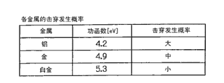
Fig. 153 is a view of an embodiment of the semiconductor inspection apparatus of the present invention, having an electrode structure to prevent punch through.
Fig. 154 is a table for explaining the operation of the device in fig. 153.
Fig. 155 is a diagram of an electrode structure in the device of fig. 153.
Fig. 156 is a diagram of an electrode configuration in the device of fig. 153.
Fig. 157 is a diagram of an electrode configuration in the device of fig. 153.
Fig. 158 is a diagram of an electrode configuration in the device of fig. 153.
Fig. 159 is a view of an embodiment of a semiconductor inspection apparatus of the present invention, with a vibration damping device.
Fig. 160(a) to 160(c) are views for explaining the apparatus shown in fig. 159.
Fig. 161 is a diagram illustrating the apparatus shown in fig. 159.
Fig. 162 is a diagram illustrating the device shown in fig. 159.
Fig. 163 is a diagram illustrating the device shown in fig. 159.
Fig. 164(a) to 164(c) are views for explaining a pattern matching method in the apparatus shown in fig. 159.
Fig. 165 is a diagram illustrating wafer holding in the semiconductor inspection apparatus of the present invention.
Fig. 166 is a view for explaining wafer holding in the semiconductor inspection apparatus of the present invention.
Fig. 167(a) and 167(b) are views for explaining wafer holding in the semiconductor inspection apparatus of the present invention.
FIG. 168 is a view of the electron beam device with suction cups illustrated in FIG. 166.
FIG. 169 is a view of the E.times.B separator in the apparatus shown in FIG. 168.
FIG. 170 is a diagram of an E B separator in the apparatus shown in FIG. 168.
FIG. 171 is a view showing an embodiment in which the inspection device of the present invention is connected to a production line.
Fig. 172(a) is a schematic view of an embodiment of a video projection electron beam apparatus capable of switching between use of secondary electrons and reflected electrons.
Fig. 172(B) is a schematic diagram of the structure of the secondary optical system.
Fig. 173 is a detailed configuration diagram of the secondary electron detection system in fig. 172 (a).
Fig. 174(a) and 174(B) are views for explaining different operation modes of the defect inspection apparatus shown in fig. 172 (a).
Fig. 175 is a diagram showing a specific structure of a lens of the secondary optical system of the defect inspection apparatus shown in fig. 172 (a).
Fig. 176(a) is a schematic view of a modified example of the projection type electron beam apparatus shown in fig. 172 (a).
Fig. 176(B) is a diagram for explaining a scanning method of the apparatus shown in fig. 176 (a).
Fig. 177(a) is a schematic view of a configuration of another modification of the map projection type electron beam apparatus shown in fig. 172 (a).
Fig. 177(B) is a diagram illustrating a scanning method of the apparatus shown in fig. 177 (a).
Fig. 178 is a view showing the structure of the vacuum chamber and the XY stage of the image projection type electron beam apparatus shown in fig. 172(a), and an inert gas circulation piping system used for the structure.
Fig. 179 is a view of an example of the differential exhaust mechanism in fig. 178.
Fig. 180 is a schematic configuration diagram of the entire inspection system.
Detailed Description
Hereinafter, embodiments of the semiconductor inspection apparatus according to the present invention will be described in detail in the following order with reference to the drawings.
1. Integral structure
1-1) Main Chamber, workbench, and vacuum delivery System Enclosure
1-1-1) active vibration isolation table
1-1-2) Main Chamber
1-1-3) XY Table
1-2) laser interferometry System
1-3) exterior of inspection part
2. Detailed description of the preferred embodiments
2-1) conveying system
2-1-1) Box holder
2-1-2) microenvironment installation
2-1-3) main casing
2-1-4) loader housing
2-1-5) loader
2-1-6) worktable apparatus
2-1-7) wafer chucking mechanism
2-1-7-1) basic construction of an electrostatic chuck
2-1-7-2) clamping mechanism for 200/300 bridge tool
2-1-7-3) wafer chucking process
2-1-8) device Structure for 200/300 bridging tools
2-2) method for transporting wafer
2-3) Electron-optical System
2-3-1) overview
2-3-2) details of the construction
2-3-2-1) electron gun (electron beam source)
2-3-2-2) Primary optical System
2-3-2-3) Secondary optical System
2-3-3) E x B cell (Wien filter)
2-3-4) Detector
2-3-5) Power supply
2-4) precharge Unit
2-5) vacuum exhaust system
2-6) control System
2-6-1) Structure and function
2-6-2) alignment procedure
2-6-3) Defect inspection
2-6-4) control system architecture
2-6-5) user interface Structure
2-7) description of other functions and structures
2-7-1) control electrode
2-7-2) method of applying potential
2-7-3) Electron Beam calibration method
2-7-4) cleaning of electrodes
2-7-5) alignment control method
2-7-6) EO correction
2-7-7) image comparison method
2-7-8) device manufacturing method
2-7-9) examination
2-8) inspection method
2-8-1) overview
2-8-2) checking algorithm
2-8-2-1) array inspection
2-8-2-2) random inspection
2-8-2-3) Focus matching
2-8-2-4) lithography margin measurement
3. Another embodiment
3-1) modifications of the stage device
3-2) Another embodiment of the Electron Beam device
3-2-1) electron gun (electron beam source)
3-2-2) electrode construction
3-3) embodiments relating to vibration damping devices
3-4) embodiments relating to the holding of wafers
3-5) embodiments of the ExB separator
3-6) embodiments of the production line
3-7) Another embodiment utilizing electrons
3-8) embodiments utilizing secondary electrons and reflected electrons
1. Integral structure
First, the overall structure of the semiconductor inspection apparatus will be described.
The overall structure of the device is described with reference to fig. 1. The apparatus includes an inspection apparatus main body, a power supply cabinet, a control cabinet, an image processing unit, a film forming apparatus, an etching apparatus, and the like. Rough pumps such as dry vacuum pumps are placed outside the clean room. As shown in fig. 2, the main part of the inspection apparatus main body includes a main casing housing an electron beam optical tube, a vacuum transfer system, a stage, a vibration isolation stage, a turbo molecular pump, and the like.
The control system includes two CRTs and has a command input function (such as a keyboard). Fig. 3 shows the structure from the functional point of view. The electron beam column mainly includes an electron optical system, a detection system, an optical microscope, and the like. The electron optical system includes an electron gun, a lens, and the like, and the transport system includes a vacuum transport robot, an atmospheric transport robot, a cartridge loader, various position sensors, and the like.
Here, the film forming apparatus, the etching apparatus, and the cleaning apparatus (not shown) are disposed in parallel in the vicinity of the inspection apparatus main body, but they may be incorporated into the inspection apparatus main body. They are used, for example, to suppress charging of the sample or to clean the sample surface. If the sputtering method is employed, one apparatus can be provided with both functions of film formation and etching.
Although not shown, the related devices may be arranged in parallel near the inspection apparatus body or may be incorporated into the inspection apparatus body for use according to the use purpose. For example, a Chemical Mechanical Polishing (CMP) apparatus and a cleaning apparatus may be incorporated in the inspection apparatus main body, or a CVD (chemical vapor deposition) apparatus may be incorporated in the inspection apparatus, and in this case, the number of units for transporting samples and the installation area can be reduced, and the advantage of reducing the transport time can be obtained.
Similarly, a film deposition apparatus such as a plating apparatus may be incorporated into the inspection apparatus main body. It may also be used in combination with a lithographic apparatus.
1-1)Main chamber, workbench and vacuum conveying system outer package
Fig. 4, 5, and 6 show main components of an inspection unit of a semiconductor inspection apparatus. The inspection unit of the semiconductor inspection apparatus includes an active vibration isolation stage 4.1 for isolating vibration from the external environment, a main chamber 4.2 as an inspection chamber, an electro-optical device 4.3 provided on the upper part of the main chamber, an XY stage 5.1 for scanning a wafer mounted in the main chamber, a laser interferometry system 5.2 for controlling the operation of the XY stage, and a vacuum transport system 4.4 attached to the main chamber, and these are arranged in the positional relationship shown in fig. 5. The inspection unit of the semiconductor inspection apparatus further includes an exterior package 6.1 that enables environmental control and maintenance of the inspection unit, and is disposed in a positional relationship shown in fig. 6.
1-1-1)Active vibration isolation table
The active vibration isolation stage 4, 1 mounts a soldering plate 5, 4 on an active vibration elimination unit 5, 3, and holds a main chamber 4, 2 as an inspection chamber, an electron optical device 4, 3 provided on the upper portion of the main chamber, a vacuum transfer system 4, 4 attached to the main chamber, and the like on the soldering plate. This can suppress vibration from the external environment in the inspection unit. In the present embodiment, when the natural frequencies are 5Hz in the X direction, 5Hz in the Y direction, and 7.6Hz in the Z direction, the suppression is within ± 25%; the control performance was such that the transmission characteristics of each axis were 0dB or less at 1Hz, -6.4dB or less at 7.6Hz, -8.6dB or less at 10Hz, and-17.9 dB or less at 20Hz (the above was a no-load state on the plate). In another configuration of the active vibration isolation stage, a main chamber, an electron optical device, and the like are held in suspension. In still another structure, a stone slab is mounted, and the main chamber and the like are held.
1-1-2)Main chamber
In order to realize a vacuum degree (10) as an inspection environment-4Pa or less), the main chamber 4 or 2 directly holds the turbo molecular pump 7 or 2 at the lower part, and has a highly accurate XY stage 5 or 1 for wafer scanning inside, and can shield the magnetic field from the outside. In the present embodiment, the following structure is adopted in order to make the flatness of the installation surface of the high-precision XY stage as good as possible. The bottom plates 7 and 3 of the main chamber are fixed to the portions 7 and 4 (in this embodiment, portions 7 and 4) having particularly good flatness remaining on the flat welding platesIn the embodiment, the flatness is 5 μm or less). Furthermore, a middle plate is arranged in the main chamber as a worktable installation surface. The middle plate is supported on the bottom plate of the main chamber through three points and is not directly influenced by the flatness of the bottom plate. In the present embodiment, the support portion is constituted by spherical seats 7 and 6. The middle plate can make the flatness of the worktable installation surface less than 5 μm under the condition of bearing the dead weight and the worktable weight. Further, in order to suppress the pressure change inside (from atmospheric pressure to a degree of vacuum 10)-4Below Pa) on the mounting surface of the worktable, and the vicinities of three-point supporting portions of the middle plate of the bottom plate are directly fixed on the welding flat plate.
In order to control the XY stage with high accuracy, a stage position measurement system including a laser interferometer is provided. The interferometer 8, 1 is disposed in a vacuum for suppressing a measurement error, and is directly fixed to a highly rigid chamber wall 7, 7 in the present embodiment in order to make the vibration of the interferometer itself, which is a direct measurement error, as zero as possible. In order to eliminate an error between the measurement position and the inspection position, the extension line of the measurement portion of the interferometer matches the inspection portion as much as possible. In addition, although the motor 8 or 2 for performing the XY operation of the table is held by the chamber wall 7 or 7 in the present embodiment, when it is necessary to further suppress the influence of the motor vibration on the main chamber, it is directly held by the welding flat plate 7 or 1 and attached to the main chamber by a structure such as a bellows that does not transmit the vibration.
The main chambers 4 and 2 are made of a material having high magnetic permeability so as to block the influence of the external magnetic field on the inspection portion. In the present embodiment, iron such as permalloy and SS400 is plated with Ni as a rust preventive coating. In another embodiment, permendur, soft magnetic iron, pure iron, or the like is used. Further, the periphery of the inspection portion in the chamber is directly covered with a material having high magnetic permeability, which also has a magnetic shielding effect.
1-1-3)XY table
The XY stage 5 · 1 can scan the wafer in vacuum with high accuracy. The strokes of X and Y are, for example, 200mm to 300mm for a 200mm wafer, and 300mm to 600mm for a 300mm wafer. The XY table of the present embodiment is driven by motors 8 and 2 for driving the X and Y axes fixed to the main chamber wall and ball screws 8 and 5 attached to these via magnetic fluid seals 8 and 3. In order to perform XY operation in a state where the X and Y driving ball screws are fixed to the chamber wall, the table structure in the present embodiment is as follows.
First, Y tables 7 and 10 are disposed on the lower layer, and ball screws 7 and 8 and cross roller guides 7 and 11 for driving are provided. The upper part of the Y table is provided with X tables 7 and 13 through intermediate tables 7 and 12 provided with X-axis driving ball screws 7 and 14. The intermediate table, the Y table and the X table are connected to each other along the Y-axis direction by a cross roller guide. Thus, when the Y-axis is moved, the Y-table and the connection portions 7 and 14 move the X-table, and the intermediate table is still in a fixed state. In another embodiment, the intermediate table has a double-layer structure disposed in parallel with the upper shaft. Further, in the XY table of another embodiment, the XY table itself is driven by a linear motor. Further, a high-precision mirror 8, 4 (in the present embodiment, flatness is λ/20 or less, and aluminum is vapor-deposited on synthetic quartz) is provided so as to enable measurement by a laser interferometer over the entire stroke.
In addition, in order to perform wafer alignment in vacuum, θ stages 7 and 15 are provided on the XY stage. In the θ table of the present embodiment, 2 ultrasonic motors are disposed for driving, and a linear scale is disposed for position control. The cables connected to the movable parts performing X, Y and θ operations are held by cable bearings held on the X table and the Y table, respectively, and connected to the outside of the main chamber through a feedthrough provided in the chamber wall.
The specifications of the present embodiment having the above-described structure are shown in tables 1 and 2.
TABLE 1
Bench scale features
| No. | Item | | Inspection method | |
| 1 | Repeat accuracy of X-axis positioning | ±3[μm]The following (graph representation) | Measuring Y-axis as center by laser length measuring instrument for |
|
| 2 | Repeat precision of Y-axis positioning | ±3[μm]The following (graph representation) | Measuring the X-axis as the center by a laser length measuring instrument for |
|
| 3 | Repeat accuracy of theta positioning | ±0.4[sec](± 2 pulses) (target) the following (numerical representation) | The deviation pulse is measured when the rotation sensor is stopped. Measured at 3 points of 0 °, -1 °, +1 °, respectively | |
| 4 | X-axis positioning accuracy | ±20[μm]The following (curves)Drawing shows | Measuring Y-axis as center by laser length measuring instrument for factory inspection | |
| 5 | Y-axis positioning accuracy | ±20[μm]The following (graph representation) | Measuring the X-axis as the center by a laser length measuring instrument for factory inspection | |
| 6 | X-axis backlash | ±1[μm]The following (numerical expression) | Measuring Y-axis as center by laser length measuring instrument for factory inspection | |
| 7 | Y-axis backlash | ±1[μm]The following (numerical expression) | Measuring the X-axis as the center by a laser length measuring instrument for factory inspection | |
| 8 | X-axis pitch | 5[sec](target) the following (graph representation) | Measuring Y-axis as center by laser length measuring instrument for factory inspection | |
| 9 | Y-axis pitch | 5[sec](target) the following (graph representation) | Measuring the X-axis as the center and both ends with a laser length measuring instrument for factory inspection | |
| 10 | X-axis yaw | 5[sec](target) the following (graph representation) | Measuring Y-axis as center and both ends with laser length measuring instrument for factory inspection | |
| 11 | Y-axis yaw | 5[sec](target) the following (graph representation) | Measuring the X-axis as the center and both ends with a laser length measuring instrument for factory inspection | |
| 12 | X-axis roll | Reference value (graph representation) | Measuring Y-axis as center and both ends with laser length measuring instrument for factory inspection | |
| 13 | Y-axis roll | Reference value (graph representation) | Using automatic collimator to measure X-axis of X-axis length measuring mirror as center | |
| 14 | Straightness in up and down direction | ±2[μm]The following (graph representation) | The measurement was carried out by a straight line calibration gauge and an ADE displacement meter. The central cross was measured. Both ends being |
|
| 15 | Degree of orthogonality of XY axes | 10[μm]The following (numerical expression) | Using a pair of orthogonality gauges and a dial gauge | |
| 16 | ORG switch and |
1±0.5[mm](numerical representation) | Measuring with a positioning laser length measuring instrument |
TABLE 2
System specification characterization
| No. | Item | | Inspection method | |
| 1 | Transverse displacement of X axis | 10mm/sec of not more than 0.5 μm, 30mm/sec of not more than 15 mm/sec. + -. 1.0 μm and not more than 30 mm/sec. + -. 2.0 μm and not more than 60mm/sec (in acceleration and deceleration, room vibration component is removed) (graph representation) | X-axis deviation value when Y-axis moves at constant speed, |
|
| 2 | X-axis positioning accuracy | Less than + -0.5 μm (koji)Line drawing shows) | The stop accuracy after moving from 0 to 20mm at 20 mm/sec. Y axis being central | |
| 3 | Y-axis positioning accuracy | Less than + -0.5 μm (shown by a graph) | The stop accuracy after moving from 0 to 20mm at 20 mm/sec. The X axis being central | |
| 4 | Non-uniform speed of Y axis | 10mm/sec of not more than. + -. 3.0. mu.m, 30mm/sec of not more than 15 mm/sec. + -. 5.0. mu.m, 60mm/sec (shown in the graph) | The variation after the constant velocity movement varies. The X axis being central | |
1-2)Laser interferometry system
The laser interferometry system includes a laser optical system parallel to the X-axis and the Y-axis and having an extension line of the optical axis corresponding to the inspection position, and an interferometer 8.1 disposed therebetween. The optical system of the present embodiment is arranged in the positional relationship shown in fig. 9 and 10. The laser beam emitted from a laser 9.1 provided on the welding plate is vertically raised by a bending mirror 9.2, and then bent parallel to the measurement surface by a bending mirror 10.1. Further, the beam is divided into an X-axis measurement beam and a Y-axis measurement beam by the spectroscopes 9 and 4, and then bent parallel to the Y-axis and the X-axis by the bending mirrors 10 and 3 and the bending mirrors 9 and 6, respectively, and introduced into the main chamber.
The following describes an adjustment method when the optical system is started. First, adjustment is made such that the laser light emitted by the laser is bent vertically by the bending mirror 9 · 2 and horizontally by the bending mirror 10 · 1. Thereafter, the bending mirror 10 or 3 is adjusted so that the optical axis returned by being bent by the bending mirror 10 or 3 and reflected by the mirror 8 or 4 provided perpendicularly to the Y axis with high accuracy completely coincides with the incident optical axis. By confirming the optical axis at a position immediately after the laser in a state where the interferometer is removed so as not to interfere with the reflected light, highly accurate adjustment can be performed. The optical axis adjustment of the X axis may be performed independently of the optical axis adjustment of the Y axis by the spectroscopes 9 and 4 and the bending mirrors 9 and 6. The key to the adjustment is the same as the Y axis. Further, after the optical axes of the incident light and the reflected light in the X axis and the Y axis are adjusted, it is necessary to match the intersection point of the respective optical axes (in the case where no mirror is assumed) with the wafer inspection position. Therefore, the carriage to which the bending mirrors 10 and 3 are fixed can move perpendicularly to the X axis, and the carriage to which the bending mirrors 9 and 6 are fixed can move perpendicularly to the X axis in a state where the incident light and the reflected light are aligned. Further, it is preferable that the bending mirrors 10 and 1, 9 and 4, 10 and 3, and 9 and 6 are vertically movable with their positional relationships maintained.
The following describes an optical axis adjustment method involved in replacing the laser of the present apparatus during operation after startup. In a device in which the inside of the main chamber is kept in a vacuum state during operation, it is difficult to adjust the optical axis of the interferometer or the like. Therefore, a plurality of targets 10 and 2 are provided on the optical path outside the main chamber, and a tool capable of determining the optical path at the time of starting only outside the main chamber is prepared. After the laser is replaced, the optical axis of the targets 10 and 2 is adjusted by only the adjustment function provided in the laser mount, so that the adjustment performed at the time of starting can be reproduced.
1-3)Exterior of inspection part
The inspection part exterior covers 4 and 7 have a function of a frame structure for maintenance. In the present embodiment, the stowable jib crane 11 or 1 is mounted on the upper part. The crane 11, 1 is mounted on a lateral guide rail 11, 2, which is further provided on a travel guide rail (vertical) 11, 3. The travel rail is normally in the stored state as shown in fig. 11, and is raised as shown in fig. 12 at the time of maintenance, so that the vertical stroke of the crane can be increased. Thus, the electro- optical devices 4 and 3, the main chamber top plate, and the XY tables 5 and 1 can be attached to and detached from the back surface of the device by a crane built in the exterior during maintenance. In another embodiment of the crane built in the exterior, a crane structure having a single shaft capable of rotating is adopted.
The exterior of the inspection unit may also serve as an environmental chamber. This has the effect of managing temperature and humidity and shielding magnetism as needed.
2. Detailed description of the preferred embodiments
Hereinafter, a preferred embodiment of the present invention will be described with reference to the drawings, in a semiconductor inspection apparatus for inspecting a wafer, which is a substrate to be inspected and has a pattern formed on a surface thereof.
2-1)Conveying system
Fig. 13 and 14 show main components of the semiconductor inspection apparatus of the present invention in a front view and a plan view. The semiconductor inspection apparatus 13, 1 includes: cassette holders 13.2 for holding cassettes in which a plurality of wafers are loaded, mini-environment devices 13.3, loader housings 13.5 constituting a working chamber, loaders 13.7 on stage devices 13.6 arranged to load wafers from the cassette holders 13.2 into the main housings 13.4, and electro-optical devices 13.8 mounted on a vacuum housing are arranged in the positional relationship shown in fig. 13 and 14.
The semiconductor inspection apparatus 13 · 1 further includes: a precharge unit 13, 9 disposed in the vacuum main housing 13, 4, a potential applying mechanism for applying a potential to the wafer, an electron beam alignment mechanism, and an optical microscope 13, 11 constituting an alignment control device 13, 10 for positioning the wafer on the stage device.
2-1-1)Box holder
The cassette holder 13 or 2 holds a plurality of (2 in the present embodiment) cassettes 13 or 12 (e.g., closed cassettes such as SMIF and FOUP manufactured by Asyst) in which a plurality of (e.g., 25) wafers are loaded in a state of being arranged in parallel in the vertical direction. As the cassette holders 13 and 2, a cassette holder suitable for the structure thereof can be arbitrarily selected and set when the cassette is transported by a robot or the like and automatically loaded into the cassette holder 13 or 2, and a cassette holder suitable for the structure of an open cassette (オ - プンカセツト) thereof can be arbitrarily selected and set when the cassette is manually loaded. The cassette holder 13 or 2 is in the form of an automatic cassette loading unit 13 or 12 in the present embodiment, and includes, for example, an elevating table 13 or 13 and an elevating mechanism 13 or 14 for vertically moving the elevating table 13 or 13, and the cassette 13 or 12 can be automatically set on the elevating table 13 or 13 in a state shown by a chain line in fig. 14, and after setting, automatically rotates to a state shown by a solid line in fig. 14 and faces the rotation axis of the 1 st transport unit in the mini-environment apparatus.
The elevating tables 13 and 13 are lowered to the state shown by the chain line in fig. 13. As described above, the cartridge holder of a known structure may be used as appropriate for the cartridge holder used in the case of automatic loading or the cartridge holder used in the case of manual loading, and detailed description of the structure and function thereof will be omitted.
In another embodiment, as shown in fig. 15, a plurality of 300mm substrates are stored in a state of being loaded in a pocket-type pocket (not shown) fixed to the inside of the box main body 15, 1, and transported, stored, and the like. The substrate transport box 15.2 includes the following parts: a substrate carrying-in/out door 15.3 which can be connected to the rectangular box main body 15.1 and the automatic opening/closing device for the substrate carrying-in/out door and mechanically opens/closes the opening on the side surface of the box main body 15.1; a cover body 15, 4 located on the opposite side of the opening part and used for covering the opening part for assembling and disassembling the filters and the fan motor; and a pocket (not shown) for holding the substrate W (fig. 13), ULPA filters 15 and 5, chemical filters 15 and 6, and fan motors 15 and 7. In the present embodiment, the substrate is carried in and out by the robot type 1 st transport units 15 and 7 of the loaders 13 and 7.
Among them, wafers as substrates loaded in the cassettes 13 and 12 are wafers to be inspected after a process for processing the wafers in a semiconductor manufacturing process or during the process. Specifically, wafers that are substrates subjected to a film formation process, CMP, ion implantation, or the like, are loaded into a cassette, with a wiring pattern formed on a surface thereof, or with a wiring pattern not yet formed thereon. Since many wafers are arranged in parallel with a vertical distance therebetween in the cassette 12, the arm of the 1 st transport unit can be moved up and down to hold the wafer at an arbitrary position by the 1 st transport unit described later. Further, in order to prevent oxidation and the like of the wafer surface after the process, a function for controlling moisture in the cassette is provided in the cassette. A desiccant such as silica gel is placed in the cartridge. In this case, any substance may be used as long as it has a drying effect.
2-1-2)Microenvironment installation
In fig. 13 to 16, the microenvironment apparatus 13, 3 includes: a casing 16.2 constituting a microenvironment space 16.1 in which atmosphere control is performed; a gas circulation device 16 or 3 for circulating a gas such as clean air in the micro-environment space 16 or 1 to control the atmosphere; a discharge device 16.4 for collecting and discharging a part of the air supplied to the micro-environment space 16.1; and a prealigner 16.5 for roughly positioning a wafer as a substrate to be inspected arranged in the micro-environment space 16.1.
The housing 16.2 has a top wall 16.6, a bottom wall 16.7, and a peripheral wall 16.8 surrounding the periphery thereof, and separates the microenvironment 16.1 from the outside. As shown in fig. 16, the gas circulation device 16, 3 includes, for controlling the atmosphere in the microenvironment 16, 1: a gas supply means 16 or 9 attached to the ceiling wall 16 or 6 in the micro-environment space 16 or 1, for purifying gas (air in the present embodiment) and causing the purified air to flow in a laminar flow directly downward through one or more gas ejection ports (not shown); a recovery pipe 16, 10 disposed on the bottom wall 16, 7 in the micro-environment space 16, 1 for recovering air flowing down to the bottom; and conduits 16 and 11 connecting the recovery pipes 16 and 10 and the gas supply units 16 and 9 and returning the recovered air to the gas supply units 16 and 9.
In the present embodiment, the gas supply unit 16 or 9 takes in about 20% of the air to be supplied from the outside of the casing 16 or 2 and purifies the air, but the ratio of the gas taken in from the outside can be arbitrarily selected. The gas supply units 16, 9 include HEPA or ULPA filters of a known structure for generating clean air. The laminar downward movement, that is, the downstream movement of the clean air is mainly caused to flow by a transport surface of a 1 st transport unit, which will be described later, disposed in the micro-environment space 16.1, and dust which may be generated by the transport unit is prevented from adhering to the wafer. Therefore, the downstream ejection port does not necessarily have to be located close to the ceiling wall as shown in the drawing, and may be located above the conveying surface of the conveying unit. Further, it is not necessary to flow in the entire microenvironment space 16 · 1.
Among them, cleanliness may be sometimes ensured by using an ion wind as clean air. Further, a sensor for observing cleanliness may be provided in the microenvironment space 16 · 1, and the apparatus may be turned off when the cleanliness deteriorates.
The case 16, 2 has access ports 13, 15 formed in portions of the peripheral walls 16, 8 adjacent to the cartridge holders 13, 2. A shut-off device of a known structure may be provided near the gates 13 and 15 to close the gates 13 and 15 from the microenvironment apparatus side. The downstream of the laminar flow formed in the vicinity of the wafer may be, for example, a flow velocity of 0.3 to 0.4 m/sec. The gas supply means 16 or 9 may be provided outside the micro-environment space 16 or 1 instead of being provided inside the same.
The discharge device 16, 4 includes: suction pipes 16 and 12 disposed below the wafer transfer surface of the transfer unit and below the transfer unit; blowers 16 and 13 disposed outside the casings 16 and 2; and conduits 16 and 14 connecting the suction pipes 16 and 12 and the blowers 16 and 13. The discharge device 16, 4 sucks gas flowing down from the periphery of the conveying unit and possibly containing dust generated in the conveying unit by using the suction pipe 16, 12, and discharges the gas to the outside of the housing 16, 2 through the conduit 16, 14 and the blower 16, 13. In this case, the exhaust gas may be discharged into an exhaust pipe (not shown) led to the vicinity of the casing 16 or 2.
The prealigner 16.5 disposed in the micro-environment space 16.1 detects an orientation flat (オリエンテ - シヨンフラツト) (which means a flat portion formed on the outer periphery of a circular wafer) formed on the wafer or one or more V-shaped notches formed on the outer periphery of the wafer optically or mechanically, and positions the wafer in the rotational direction about the wafer axis O-O with an accuracy of about ± 1 degree in advance. The prealigners 16 and 5 constitute a part of a mechanism for determining the coordinates of the inspection object, and serve as coarse positioning of the inspection object. Since the prealigners 16 and 5 themselves may have a known structure, description of the structure and operation thereof will be omitted.
Although not shown, a recovery pipe for a discharge device may be provided also below the prealigners 16 and 5 to discharge air containing dust discharged from the prealigners 16 and 5 to the outside.
2-1-3)Main shell
In fig. 13 to 15, the main housings 13 and 4 constituting the working chambers 13 and 6 include housing main bodies 13 and 17, and the housing main bodies 13 and 17 are supported by housing support devices 13 and 20 mounted on vibration isolation devices 13 and 19, which are vibration isolation devices disposed on the pedestals 13 and 18. The casing support devices 13 and 20 include frame structures 13 and 21 assembled into a rectangular shape. The casing bodies 13 and 17 are disposed and fixed to the frame structures 13 and 21, and include bottom walls 13 and 22 and top walls 13 and 23 placed on the frame structures, and peripheral walls 13 and 24 connected to the bottom walls 13 and 22 and the top walls 13 and 23 and surrounding the periphery thereof, and isolate the working chambers 13 and 16 from the outside. The bottom walls 13 and 22 are formed of relatively thick steel plates in the present embodiment so as not to be deformed by a load of equipment such as a table device placed thereon, but may have other structures.
In the present embodiment, the casing main body and the casing support devices 13 and 20 are assembled into a rigid structure, and the vibration isolation devices 13 and 19 prevent the vibration from the floor on which the pedestals 13 and 18 are installed from being transmitted to the rigid structure. Among the peripheral walls 13 and 24 of the housing bodies 13 and 17, an inlet/outlet 14 and 1 for carrying in and out wafers is formed in a peripheral wall adjacent to a loader housing described later.
The vibration isolators 13 and 19 may be of an active type having air cushions, magnetic bearings, or the like, or may be of a passive type having these. Since these are well-known structures, descriptions of the structures and functions thereof are omitted. The working chambers 13 and 16 are held in a vacuum atmosphere by a vacuum device (not shown) of a known structure. A control device 2 for controlling the operation of the entire apparatus is disposed below the stage frames 13 and 18. The pressure of the main housing is normally maintained at 10-4~10-6Pa。
2-1-4)Loader shell
In fig. 13 to 15 and 17, the loader housing 13 and 5 includes a housing main body 14 and 4 constituting the 1 st loading chamber 14 and 2 nd loading chamber 14 and 3. The housing main body 14, 4 has a bottom wall 17, 1, a top wall 17, 2, a peripheral wall 17, 3 surrounding the periphery, and a partition wall 14, 5 partitioning the 1 st loading chamber 14, 2 and the 2 nd loading chamber 14, 3, and can isolate the two loading chambers from the outside. The partition walls 14 and 5 are formed with ports 17 and 4 as openings for exchanging wafers between the two load chambers. In addition, the portions of the peripheral walls 17 and 3 adjacent to the microenvironment and the main casing are formed with ports 14 and 6 and 14 and 7.
The housing main bodies 14 and 4 of the loader housings 13 and 5 are mounted on and supported by the frame structural bodies 13 and 21 of the housing support devices 13 and 20. Therefore, the vibration of the floor is not transmitted to the loader housings 13 and 5. The inlet and outlet 14.6 of the loader shell 13.5 is matched and integrated with the inlet and outlet 13.25 of the shell 16.2 of the mini-environment device 13.3, and a shutoff device 14.8 for selectively preventing the communication between the mini-environment space 16.1 and the 1 st loading chamber 14.2 is arranged on the inlet and outlet.
The shut-off device 14, 8 has sealing materials 13, 26 surrounding the periphery of the entrances 13, 25 and 14, 6 and fixed in close contact with the side walls 17, 3, doors 13, 27 interlocking with the sealing materials 13, 26 and preventing air from flowing through the entrances and exits, and driving devices 13, 28 for driving the doors. Further, the inlet/outlet 14.7 of the loader housing 13.5 is matched with the inlet/outlet 14.1 of the housing main body 13.17, and a shut-off device 13.29 for selectively sealing and preventing communication between the 2 nd loading chamber 14.3 and the working chamber 13.16 is provided therein. The shut-off device 13, 29 has a sealing material 13, 30 which surrounds the periphery of the access ports 14, 7 and 14, 1, is in close contact with the side walls 17, 3 and 13, 24, and is fixed to the side walls, a door 14, 27 which is interlocked with the sealing material 13, 30 and prevents air from flowing through the access port, and a driving device 13, 31 which drives the door.
Further, at the opening formed in the partition wall 14, 5, shut-off means 14, 10 for closing it with a door and selectively sealing the communication between the 1 st and 2 nd loading chambers are provided. These shut-off devices 14, 8, 13, 29 and 14, 10 can hermetically seal the chambers when in the closed state. These shutoff devices may be well known, and detailed description of their construction and operation is omitted.
However, the support method of the casing 16.2 of the mini-environment device 13.3 is different from the support method of the load chamber, and in order to prevent the vibration from the floor from being transmitted to the load chamber casing 13.5 and the main casing 13.4 through the mini-environment device 13.3, a vibration-proof cushion material may be disposed between the casing 16.2 and the loader casing 13.5, and the periphery of the entrance may be air-tightly surrounded.
In the 1 st loading chamber 14, 2, a wafer rack 14, 11 is disposed which is vertically spaced and supports a plurality of (2 in the present embodiment) wafers in a horizontal state. As shown in fig. 18, the wafer cassette 14, 11 includes support columns 18, 2 fixed to four corners of a rectangular substrate 18, 1 in an upright state while being spaced apart from each other, and double- layered support portions 18, 3 and 18, 4 are formed on the support columns 18, 2, respectively, and the peripheral edge of the wafer W is supported and held on the support portions. The tip of an arm of the 1 st and 2 nd transfer units described later is brought into proximity with the wafer from between the adjacent support columns, and the wafer is held by the arm.
The load chambers 14, 2 and 14, 3 can be controlled to have an atmosphere controlled by a vacuum exhaust apparatus (not shown) having a known structure including a vacuum pump (not shown)High vacuum state (vacuum degree of 10)-4~10-6Pa) is added. In this case, the 1 st loading chamber 14 or 2 can be kept in a low vacuum atmosphere as a low vacuum chamber, and the 2 nd loading chamber 14 or 3 can be kept in a high vacuum atmosphere as a high vacuum chamber, thereby effectively preventing contamination of the wafer. By adopting such a configuration, the wafer which is accommodated in the loading chamber and then subjected to the defect inspection can be transferred to the working chamber in time. By using such a load cell, productivity of defect inspection can be improved together with the principle of the multi-beam electronic apparatus described later, and the degree of vacuum in the vicinity of the electron source, which is required to be in a high vacuum state in the storage state, can be set to a high vacuum state as much as possible.
The 1 st and 2 nd loading chambers 14, 2 and 14, 3 are connected to a vacuum exhaust pipe and a ventilation pipe (not shown) for an inert gas (for example, dry pure nitrogen), respectively. Thus, the atmospheric pressure state in each loading chamber is realized by the inert gas ventilation (the inert gas is injected to prevent oxygen and the like other than the inert gas from adhering to the surface). Since the apparatus for conducting such inert gas aeration itself may have a known structure, detailed description thereof will be omitted.
Among them, in the inspection apparatus of the present invention using an electron beam, a typical lanthanum hexaboride (LaB) is used as an electron source of an electron optical system described later6) When the wafer is once heated to a high temperature enough to emit thermal electrons, it is important not to contact oxygen or the like as much as possible to shorten the lifetime, and the atmosphere control can be performed more reliably by performing the above-described atmosphere control in a step before the wafer is introduced into a chamber in which an electron optical system is disposed.
2-1-5)Loader
The loader 13, 7 includes a 1 st transport unit 16, 14 of a robot type disposed in a housing 16, 2 of the mini-environment apparatus 13, 3, and a 2 nd transport unit 14, 12 of a robot type disposed in a 2 nd loading chamber 14, 3.
The 1 st conveying units 16 and 14 are provided with drive parts 16 and 15 which can rotate around the axis O 1-O1RotateThe multi-link arms 16 and 16. As the arm of the multi-link, any configuration may be used, and in the present embodiment, there are three portions mounted so as to be rotatable with respect to each other.
One part of the arms 16 and 16 of the 1 st transport units 16 and 14, that is, the 1 st part on the side closest to the driving parts 16 and 15, is attached to shafts 16 and 17 rotatable by a driving mechanism (not shown) of a known structure provided in the driving parts 16 and 15. The arms 16, 16 can pass through the shafts 16, 17 around the axis O1-O1Rotate and are able to rotate about the axis O as a whole by relative rotation between the parts1-O1And expands and contracts in the radial direction. At the tip of the 3 rd portion of the arms 16 and 16 farthest from the shafts 16 and 17, holding devices 14 and 13 for holding a wafer, such as a mechanical chuck or an electrostatic chuck, having a known structure, are provided. The driving units 16 and 15 can be moved in the vertical direction by lifting mechanisms 16 and 18 having a known structure.
The arms 16 and 16 of the first transport units 16 and 14 are extended in the direction M1 or M2 toward one of the two cassettes held by the cassette holder, and wafers stored in the cassettes are held and taken out by suction pads (not shown) mounted on the arm 1 or the tip of the arm. Thereafter, the arm is retracted (the state shown in fig. 14), and the arm is rotated to a position where it can be extended in the direction M3 of the prealigner 16 or 5 and stopped at the position. The arm is then extended again to place the wafer held on the arm on the prealigner 16 · 5. After receiving the wafer from the prealigner 16 or 5 in the opposite direction as described above, the arm is further rotated, and stopped at a position (direction M4) where it can be extended into the 2 nd load chamber 14 or 2, and the wafer is transferred to the wafer tray in the 2 nd load chamber 14 or 2. When the wafer is mechanically held, a peripheral edge portion (a range of about 5mm from the peripheral edge) of the wafer is held. This is because devices (circuit wirings) are formed on the wafer except for the peripheral portion, and if the wafer is held at this portion, the devices are damaged or defective.
The 2 nd transfer units 14 and 12 have substantially the same structure as the 1 st transfer unit, and are different only in that the wafer is transferred between the wafer cassette and the mounting surface of the stage device, and therefore, detailed description thereof is omitted.
In the above loaders 13 and 7, the 1 st and 2 nd transfer units 16 and 14 and 12 are held in a substantially horizontal state to transfer wafers from a cassette held by a cassette holder to the stage devices 13 and 6 disposed in the chambers 13 and 16 and vice versa, and the vertical movement of the arm of the transfer unit is performed only when taking out and inserting the wafers from and into the cassette, placing and taking out the wafers on and from the wafer holders, and placing and taking out the wafers on and from the stage devices. Therefore, the movement of a large wafer, for example, a wafer having a diameter of 300mm can be smoothly performed.
Since the stage has a mechanism for applying a reverse bias to the wafer, the stage has the following mechanism: when the arm is moved to the stage for placing a wafer thereon or to take out a wafer therefrom, the arm is set to a potential equal to or close to that of the stage or to a floating potential, thereby avoiding problems such as discharge due to short-circuiting of the potential.
2-1-6)Work table device
The table devices 13 and 6 include: fixed stands 13 and 32 disposed on the bottom walls 13 and 22 of the main housings 13 and 4; y stages 13 and 33 that move on the fixed stage in the Y direction (direction perpendicular to the paper surface in fig. 1); x stages 13 and 34 that move in the X direction (left-right direction in fig. 1) on the Y stage; rotary tables 13 and 35 rotatable on the X table; and racks 13 and 36 arranged on the rotating tables 13 and 35. The wafers are releasably held on the wafer mounting surfaces 14 and 14 of the shelves 13 and 36. The shelves 13, 36 may be of known construction capable of releasably holding wafers by mechanical or electrostatic chucks. The stage devices 13 and 6 can position the wafer held on the stage on the mounting surfaces 14 and 14 with high accuracy in the X direction, the Y direction, and the Z direction (vertical direction in fig. 13) with respect to the electron beam irradiated from the electron optical device, and further in the direction (θ direction) around the axis perpendicular to the supporting surface of the wafer, by operating the plurality of stages by using the servo motors, encoders, and various sensors (not shown).
The positioning in the Z direction may be, for example, a position of a mounting surface on the fine-adjustable rack in the Z direction. In this case, a reference position of the mounting surface is detected by a position measuring device (laser interference distance measuring device using the principle of interferometer) composed of a fine diameter laser, the position is controlled by a feedback circuit (not shown), the position of the notch or the orientation flat of the wafer is measured together with or instead of the position, the flat position and the rotational position of the wafer with respect to the electron beam are detected, and the control is performed by rotating the turntable by a stepping motor or the like capable of controlling a fine angle.
In order to prevent dust in the working chamber as much as possible, the servo motors 14, 15, 14, 16 and the encoders 14, 17, 14, 18 for the table device are disposed outside the main housing 13, 4. Since the table devices 13 and 6 may have a known structure used in a stepper (ステツパ), for example, detailed description of the structure and operation thereof will be omitted. Since the laser interference distance measuring device may have a known structure, detailed description of the structure and operation thereof will be omitted.
The signal obtained by inputting the rotational position or X, Y position of the wafer with respect to the electron beam to a signal detection system or an image processing system described later can be normalized. The wafer chuck mechanism provided in the holder applies a voltage for chucking the wafer to the electrode of the electrostatic chuck, and positions the wafer by pressing three points on the outer peripheral portion of the wafer (preferably, equally spaced in the circumferential direction). The wafer chuck mechanism comprises two fixed positioning pins and a pressing type locking pin. The locking pin can realize automatic clamping and automatic releasing, and forms a conducting part for applying voltage.
In the present embodiment, the table moving in the left-right direction is an X table and the table moving in the up-down direction is a Y table in fig. 14, but the table moving in the left-right direction may be a Y table and the table moving in the up-down direction may be an X table in the drawing.
2-1-7)Wafer chucking mechanism
2-1-7-1)Of electrostatic chucksBasic structure
In order to accurately adjust the focal point of the electron optical system to the sample surface in a short time, it is preferable to reduce the unevenness of the sample surface, i.e., the wafer surface as much as possible. Therefore, the wafer is attracted to the surface of the electrostatic chuck manufactured with good flatness (preferably, flatness of 5 μm or less).
The electrode structure of the electrostatic chuck is of a unipolar type and a bipolar type. The unipolar type is a method of attracting a wafer by bringing the wafer into conduction with a wafer in advance and applying a high voltage (generally, several tens to several hundreds volts) between the wafer and 1 electrostatic chuck electrode, and the bipolar type can attract a wafer by applying a voltage of opposite positive and negative polarities to 2 electrostatic chuck electrodes without bringing the wafer into conduction. However, in general, in order to obtain stable adsorption conditions, it is necessary to interleave 2 electrodes in a comb shape, and the electrode shape is complicated.
On the other hand, in order to inspect a sample, a predetermined voltage (deceleration voltage) needs to be applied to the wafer in order to obtain an imaging condition of the electron optical system or to change the state of the sample surface to a state that can be easily observed with electrons. The deceleration voltage needs to be applied to the wafer, and the electrostatic chuck needs to be of the unipolar type in order to stabilize the potential on the wafer surface. (however, as described later, it is necessary to operate the electrostatic chuck as a bipolar type before the conduction is established between the wafer and the conduction pin, and therefore, the electrostatic chuck has a structure that can be switched between a unipolar type and a bipolar type.)
Therefore, it is necessary to make mechanical contact with the wafer to achieve conduction. However, the need to prevent contamination of the wafer is becoming increasingly stringent, requiring mechanical contact to be avoided, and sometimes not allowed, to the edge of the wafer. In this case, conduction must be achieved at the back side of the wafer.
A silicon oxide film is generally formed on the back surface of the wafer, and conduction cannot be obtained directly. Therefore, by bringing the needles at 2 or more positions into contact with the back surface of the wafer and applying a voltage between the needles, the oxide film can be locally broken and conduction can be established with the silicon of the wafer base material. The voltage applied to the needle is a direct or alternating voltage of about several hundred V. The material of the needle is required to be nonmagnetic and wear-resistant, and is a high-melting point material, and tungsten or the like is considered. Further, it is also effective to coat TiN or diamond on the surface for the purpose of imparting durability or preventing contamination of the wafer. In addition, it is effective to apply a voltage between the pins and measure a current in order to confirm conduction with the wafer.
Against the above background, a chucking mechanism shown in fig. 19 was produced. The electrostatic chuck is provided with electrodes 19.1, 19.2 preferably interdigitated in a comb shape for stably attracting the wafer W, 3 pressing pins 19.3 for transferring the wafer, and 2 or more conduction pins 19.4 for applying a voltage to the wafer. Further, a correction ring 19.5 and a wafer dropping mechanism 19.6 are disposed around the electrostatic chuck.
When the wafer W is transferred by the robot, the pressing pins 19 and 3 protrude from the surface of the electrostatic chuck in advance, and after the wafer W is placed thereon by the operation of the robot, the pressing pins 19 and 3 are gradually lowered to place the wafer W on the electrostatic chuck. When the wafer W is taken out from the electrostatic chuck, the wafer W is transferred to the robot arm by reversing the operation. The pressing pins 19 and 3 should be made of a material that does not cause positional displacement of the wafer or contamination, and preferably made of a material such as silicone rubber, fluororubber, ceramics such as SiC or alumina, or a resin such as teflon or polyimide.
There are several methods as the driving mechanism of the push pins 19 and 3. One is to provide a non-magnetic actuator at the lower portion of the electrostatic chuck. This may be a method of directly linearly driving the push pin by an ultrasonic linear motor, a method of linearly driving the push pin by combining a rotary ultrasonic motor and a ball screw or a rack and pinion transmission, or the like. This method can compactly integrate the pushing mechanism on the stage of the XY stage on which the electrostatic chuck is mounted, but the number of wirings for actuators, limit sensors, and the like is very large. These wirings are connected from the XY-stage to the wall surface of the sample chamber (main chamber or main housing) and are bent in accordance with the movement of the stage, and therefore, need to be arranged at a large bending degree R, and occupy a space. Further, since the wiring is required to be replaced periodically or the source of particle generation, the number of uses is preferably the minimum.
Therefore, the driving force is supplied from the outside as another method. After the stage is moved to a position where the wafer W is attached and detached, a shaft protruding into a vacuum state through a bellows is driven by an air cylinder provided outside the chamber, and presses a shaft of a pressing drive mechanism provided below the electrostatic chuck. The shaft is connected with a gear rack transmission device or a connecting rod mechanism in the pushing and pressing driving mechanism, and the reciprocating movement of the shaft is linked with the up-and-down movement of the pushing and pressing pin. When the wafer W is transferred to and from the robot, the pressing pins 19 and 3 are raised by adjusting the speed to an appropriate value by the controller and pushing the shaft out into a vacuum by the air cylinder.
The driving source of the shaft from the outside is not limited to the cylinder, and may be a combination of a servo motor and a rack and pinion gear or a ball screw. Further, an external drive source may be used as the rotation shaft. In this case, a mechanism is built in which the rotation shaft converts the rotation into the linear motion of the pusher via a vacuum seal mechanism such as a magnetic fluid seal or a thrust drive mechanism.
The correction rings 19 and 5 have a function of keeping the electric field distribution at the wafer end uniform, and are applied with substantially the same potential as the wafer. However, in order to eliminate the influence of a minute gap between the wafer and the correction ring or a minute difference in surface height between the wafer and the correction ring, a potential slightly different from the potential at the wafer end portion may be applied. The correction ring may have a width of about 10 to 30mm in the radial direction of the wafer, and a nonmagnetic and electrically conductive material such as titanium, phosphor bronze, TiN, or TiC-coated aluminum may be used.
The through pins 19 and 4 are supported by springs 19 and 7, and are lightly pressed against the back surface of the wafer by a spring force after the wafer is mounted on the electrostatic chuck. In this state, electrical conduction with the wafer W is achieved by applying a voltage as described above.
The electrostatic chuck body is composed of nonmagnetic planar electrodes 19.1 and 19.2 such as tungsten and a dielectric formed thereon. As a material for the dielectric, alumina, aluminum nitride, titanium nitride,Polyimide, and the like. The volume resistivity of ceramics such as alumina is generally 1014Since the material is a complete insulator of approximately Ω cm, charge transfer does not occur inside the material, and coulomb force acts as an adsorption force. On the contrary, by slightly adjusting the ceramic composition, the volume resistivity can be set to 1010Since charge transfer occurs in the material by this operation, a so-called johnson rabick force, which is stronger than coulomb force, acts as a force for attracting the wafer. The stronger the attraction force is, the lower the applied voltage can be made accordingly, the larger the margin of breakdown can be made, and the more easily stable attraction force can be obtained. Further, by processing the electrostatic chuck surface into, for example, a dimple shape, even if particles or the like adhere to the electrostatic chuck surface, the particles may fall on the valley portion of the dimple, and therefore, an effect of reducing the possibility of affecting the flatness of the wafer is expected.
According to the above, the volume resistivity of the electrostatic chuck material is adjusted to 1010Aluminum nitride or alumina ceramics having a thickness of approximately Ω cm is practically used in which pits or other irregularities are formed on the surface and the flatness of the surface formed by the collection of convexities is processed to approximately 5 μm.
2-1-7-2)Clamping mechanism for 200/300 bridging tool
It is sometimes required that the apparatus can inspect 2 kinds of wafers of 200mm and 300mm without mechanical modification. In this case, the electrostatic chuck must chuck 2 kinds of wafers, and a correction ring having a size corresponding to the wafer is placed on the peripheral edge of the wafer. Fig. 19(a), (B), and 20 show the configuration for this.
Fig. 19(a) shows a state where a 300mm wafer W is mounted on the electrostatic chuck. The correction ring 19 or 1 having an inner diameter slightly larger than the size of the wafer W (a gap of about 0.5 mm) is positioned by the recess and placed on a metallic ring-shaped member on the outer periphery of the electrostatic chuck. The alignment ring 19.1 is provided with 3 wafer dropping mechanisms 19.2. The wafer drop mechanism 19.2 is driven by a vertical driving mechanism linked with a driving mechanism of the pushing pin 19.3, and is supported rotatably about a rotation shaft provided on the correction ring 19.1.
When the wafer W is received from the robot hand, the pressing pin driving mechanism operates to press the pressing pins 19 and 3 upward. At a suitable interval from this, the wafer drop mechanism 19.2 provided on the correction ring 19.1 is also rotated by the driving force as shown in fig. 19 (B). Then, the wafer dropping mechanism 19 or 2 forms a tapered surface for guiding the wafer W around the electrostatic chuck. Subsequently, after the wafer W is mounted on the pushed-up pressing pins 19 and 3, the pressing pins 19 and 3 are lowered. When the driving force is appropriately adjusted to act on the wafer dropping mechanism 19.2 in accordance with the lowering of the pushing pin 19.3, the wafer W is placed on the electrostatic chuck with the position thereof corrected by the tapered surface of the dropping mechanism 19.2 so that the center of the wafer W and the center of the electrostatic chuck are almost aligned.
Preferably, a low friction material such as teflon, preferably a conductive low friction material (e.g., conductive teflon, conductive diamond-like carbon, TIN coating) is formed on the tapered surface of the drop-in means 19 or 2. In the figure, reference numeral A, B, C, D, E denotes a terminal (described later) for applying a voltage, and 19 and 4 denote wafer guide pins for detecting whether or not the wafer W is placed on the electrostatic chuck, and are pressed by springs 19 and 5.
Fig. 20 shows a state where a 200mm wafer W is mounted on the same electrostatic chuck. Since the wafer diameter is smaller than the electrostatic chuck and the electrostatic chuck surface is exposed, the correction ring 20.1 having a size that completely hides the electrostatic chuck is mounted. The positioning of the correction ring 20 · 1 is the same as in the case of the correction ring for 300 mm.
The correction ring 20.1 has a step at its inner periphery and is accommodated in the annular groove 20.2 on the electrostatic chuck side. This is a structure hidden by a conductor (correction ring 20 · 1) so that the electrostatic chuck surface is not seen from the gap between the inner periphery of the correction ring 20 · 1 and the outer periphery of the wafer W when a 200mm wafer is mounted. This is because, if a structure is adopted in which the surface of the electrostatic chuck is visible, when an electron beam is irradiated, electric charges are charged on the surface of the electrostatic chuck, and the potential of the sample surface is disturbed.
The replacement of the correction ring 20 · 1 is performed as follows: a calibration ring replacement station is provided at a predetermined position in the vacuum chamber, and from there, a calibration ring of a desired size is transferred by a robot and attached to the electrostatic chuck (inserted into the pocket).
The 200mm alignment ring is also provided with a wafer dropping mechanism 20.2 in the same manner as 300 mm. On the electrostatic chuck side, a gap is formed so as not to interfere with the wafer dropping mechanism 20 or 2. The method of mounting the wafer on the electrostatic chuck was exactly the same as the case of 300 mm. Note that A, B, C, D, E denotes a terminal for applying a voltage, 20 · 3 denotes a push pin similar to the push pin 19 · 3, and 20 · 4 denotes a wafer guide pin similar to the wafer guide pin 19 · 4.
FIGS. 20-1(A) and 20-1(B) are schematic views showing the structure of an electrostatic chuck which can handle both a 300mm wafer and a 200mm wafer, wherein (A) shows a state in which the 300mm wafer is mounted and (B) shows a state in which the 200mm wafer is mounted. As can be understood from fig. 20-1(a), the electrostatic chuck has a width capable of mounting a 300mm wafer, and as shown in fig. 21-2 (B), the electrostatic chuck has a width capable of mounting a 200mm wafer at its central portion, and grooves 20 and 6 are provided around the central portion to fit the inner peripheral portion of the correction ring 20 and 1. Here, reference numeral A, B, C, D, E denotes a terminal for applying a voltage.
In the case of the electrostatic chuck shown in fig. 20-1(a) and (B), whether or not the wafer is placed on the electrostatic chuck, whether or not the wafer is correctly placed on the electrostatic chuck, whether or not there is a correction ring, and the like are optically detected. For example, by providing an optical sensor above the electrostatic chuck and detecting the optical path length when light emitted from the optical sensor is reflected by the wafer and returned to the optical sensor again, it is possible to detect whether the wafer is placed horizontally or obliquely. The presence or absence of the correction ring can be detected by providing a light emitter that irradiates an appropriate point in a place where the correction ring is to be placed obliquely, and a light receiver that receives reflected light from the correction ring. Further, by providing a combination of a light emitter which is positioned at an appropriate point on the position where the correction ring for the 200mm wafer is placed and a light receiver which receives reflected light from the correction ring, and a combination of a light emitter which is positioned at an appropriate point on the position where the correction ring for the 300mm wafer is placed and a light receiver which receives reflected light from the correction ring, it is possible to detect which light receiver receives reflected light, and it is possible to detect which of the correction ring for the 200mm wafer and the correction ring for the 300mm wafer is placed on the electrostatic chuck.
2-1-7-3)Wafer chucking process
The wafer chucking mechanism having the structure described above chucks a wafer in the following procedure.
(1) The wafer size-compatible alignment ring is transferred by a robot and mounted on the electrostatic chuck.
(2) The wafer is placed on the electrostatic chuck by the wafer transfer by the robot and the up-and-down movement of the pushing pin.
(3) A bipolar voltage is applied to the electrostatic chuck (a voltage opposite in polarity to the positive and negative voltages is applied to the terminal C, D) to chuck the wafer.
(4) A predetermined voltage is applied to the guide pins to break down an insulating film (oxide film) on the back surface of the wafer.
(5) The current between the terminals A, B is measured to confirm whether or not conduction is achieved with the wafer.
(6) The electrostatic chuck is switched to unipolar adsorption. (grounding terminal A, B and applying the same voltage to terminal C, D)
(7) The voltage of the terminals A (and B) is reduced while maintaining the potential difference between the terminals A (and B) and the terminals C (and D), and a predetermined deceleration voltage is applied to the wafer.
2-1-8)Device structure for 200/300 bridging tool
Fig. 21 and 22 show the apparatus structure capable of inspecting both the 200mm wafer and the 300mm wafer without modification of the mechanical structure. The following description deals with differences from a 200mm wafer-only apparatus or a 300mm wafer-only apparatus.
At the installation place 21 or 1 of the wafer cassette which is replaced according to each specification such as 200/300mm wafer, FOUP, SMIF, open cassette, etc., a wafer cassette corresponding to the wafer size or the kind of the wafer cassette determined according to the customer specification can be installed. The atmospheric transfer robot 21 or 2 has a robot hand capable of supporting different wafer sizes, that is, a plurality of wafer drop-in portions are provided in accordance with the wafer size, and are mounted on the robot hand at positions corresponding to the wafer size. The atmospheric transfer robot 21 or 2 takes out the wafer from the prealigner 21 or 3 and transfers the wafer into the preload chamber 21 or 4 after the wafer is transferred from the installation place 21 or 1 to the prealigner 21 or 3 and the direction of the wafer is adjusted.
The wafer cassette in the preload chamber 21 or 4 has a similar structure, in which a plurality of drop-in portions corresponding to the sizes of the wafers are formed in the wafer support portions of the wafer cassette, and the wafer loaded on the robot hand of the atmospheric transfer robot 21 or 2 is loaded in the drop-in portion corresponding to the size of the wafer by adjusting the height of the robot hand, and the wafer is inserted into the wafer cassette, and thereafter, the wafer is loaded in a predetermined drop-in portion of the wafer support portion by lowering the robot hand.
The wafer placed on the wafer cassette in the preload chamber 21, 4 is then taken out of the preload chamber 21, 3 by the vacuum transfer robot 21, 6 provided in the transfer chamber 21, 5 and transferred to the table 21, 8 in the sample chamber 21, 7. The hand of the vacuum transfer robot 21 or 6 also has a plurality of drop-in portions corresponding to the wafer size, as in the air transfer robot 21 or 2. The wafer mounted on the predetermined drop-in portion of the robot is mounted on the electrostatic chuck on which the alignment ring 21 or 9 corresponding to the size of the wafer is mounted in advance on the tables 21 or 8, and is fixed by the electrostatic chuck. The correction rings 21 and 9 are mounted on correction ring holders 21 and 10 provided in the conveyance chambers 21 and 5. Therefore, the vacuum transfer robots 21 and 6 take out the wafer-sized alignment rings 21 and 9 from the alignment ring holders 21 and 10 and transfer the same to the electrostatic chucks, fit the alignment rings 21 and 9 into the positioning recesses formed in the outer peripheral portions of the electrostatic chucks, and place the wafers on the electrostatic chucks.
When the correction ring is replaced, the reverse operation is performed. That is, the correction ring 21 or 9 is detached from the electrostatic chuck by the robot 21 or 6, the correction ring is returned to the correction ring holder 21 or 10 in the transfer chamber 21 or 5, and the correction ring corresponding to the wafer size to be inspected is transferred from the correction ring holder 21 or 10 to the electrostatic chuck.
In the inspection apparatus shown in fig. 21, since the prealigner 21, 3 is disposed in the vicinity of the preload chamber 22, 4, even when the alignment of the wafer is insufficient and the correction ring cannot be mounted in the preload chamber, it is easy to return the wafer to the prealigner and perform the alignment again, which has an advantage of reducing the time loss in the process.
Fig. 22 shows an example in which the placement location of the correction ring is changed, and the correction ring holders 21 and 10 are omitted. In the preload chamber 22 · 1, a wafer stage and a correction ring stage are formed in layers, which are provided on the lifter and can move up and down. First, in order to set a correction ring corresponding to the size of a wafer to be inspected on an electrostatic chuck, the vacuum transfer robot 21 · 6 moves the lifter of the preload chamber 22 · 1 to a position where the correction ring can be taken out. After the alignment ring is set on the electrostatic chuck by the vacuum transfer robot 21 or 6, the lifter is operated so that the wafer to be inspected can be transferred, and the wafer is taken out of the wafer cassette by the vacuum transfer robot 21 or 6 and placed on the electrostatic chuck. In this configuration, although the lifter is required for the preload chamber 22 · 1, the vacuum transfer chamber 21 · 5 can be made small, which is effective in reducing the floor space of the apparatus.
The sensor for detecting the presence or absence of a wafer on the electrostatic chuck is preferably provided at a position corresponding to a different wafer size, but in the case where this is not possible, a plurality of sensors functioning in the same manner may be provided for each wafer size.
In the inspection apparatus described according to fig. 21, the following procedure is adopted: the calibration ring is placed on the electrostatic chuck and the wafer is positioned to conform to the inner diameter of the calibration ring. Therefore, in the inspection apparatus shown in fig. 22, the following procedure is adopted: the calibration ring is mounted on the wafer in the preload chamber 22 · 1, and the wafer on which the calibration ring is mounted is transported for each calibration ring, introduced into the sample chamber 21 · 7, and mounted on the electrostatic chuck on the stage. As a mechanism for realizing this, there is an elevating mechanism which moves an elevator up and down and transfers a wafer from an atmospheric transfer robot to a vacuum transfer robot as shown in fig. 22-1 and 22-2. The process of conveying the wafer by this mechanism will be described below.
As shown in fig. 22-1(a), the elevating mechanism provided in the preload chamber has a multi-stage (double-stage in the figure) correction ring support table capable of moving in the up-down direction. The upper stage 22.2 and the lower stage 22.3 are fixed to the 1 st stage 22.5 which is raised and lowered by the rotation of the 1 st motor 22.4, whereby the 1 st stage 22.5 and the upper and lower stage 22.2 and 22.3 are moved upward or downward by the rotation of the 1 st motor 22.4.
On each of the correction ring support tables, the correction rings 22 and 6 having inner diameters corresponding to the sizes of the wafers are placed. The correction rings 22 and 6 were prepared in 2 types having different inner diameters for 200mm wafers and 300mm wafers, and the outer diameters of these correction rings were the same. Thus, by using the correction rings of the same outer diameter, compatibility is brought about, and the 200mm and 300mm products can be loaded into the preload chamber by a free combination. That is, in a production line in which 200mm wafers and 300mm wafers are mixed and flowed, the upper layer is set to 300mm, and the lower layer is set to 200mm, and the inspection can be flexibly performed regardless of which wafer is transferred. In addition, in a production line in which wafers of the same size are transferred, the wafers of the upper and lower layers can be alternately inspected by setting the upper and lower layers to 200mm or 300mm, and thus the productivity can be improved.
The 2 nd motors 22 and 7 are mounted on the 1 st tables 22 and 5, and the 2 nd tables 22 and 8 are mounted on the 2 nd motors 22 and 7 so as to be capable of ascending and descending. The upper wafer support tables 22 and 9 and the lower wafer support tables 22 and 10 are fixed to the 2 nd tables 22 and 8. Thus, when the 2 nd motors 22 and 7 rotate, the 2 nd stages 22 and 8 and the upper and lower wafer support stages 22 and 9, 22 and 10 move upward or downward integrally.
Accordingly, as shown in fig. 22-1(a), the wafer W is loaded onto the hand of the atmospheric transfer robot 21 or 2 and carried into the preload chamber 22 or 1, and then as shown in (B), the 2 nd motor 22 or 7 is rotated in the 1 st direction to move the wafer support tables 22 or 9 and 22 or 10 upward, thereby placing the wafer W on the upper wafer support table 22 or 9. Thereby, the wafer W is moved from the atmospheric transfer robot 21 · 2 to the wafer support table 22 · 9. Thereafter, as shown in (C), the air transfer robot 21, 2 is retracted, and when the air transfer robot 21, 2 is completely retracted, as shown in (D), the 2 nd motor 22, 7 is rotated in the direction opposite to the 1 st direction to move the wafer support tables 22, 9, 22, 10 downward. Thereby, the wafer W is placed on the upper correction ring 22 or 6.
Next, as shown in (E), the hand of the vacuum transfer robot 21 · 6 is inserted into the preload chamber 22 · 1 and stopped at the lower side of the correction ring 22 · 6. In this state, the 1 st motor 22, 4 is rotated, and the 1 st stage 22, 5, the upper and lower correction ring support stages 22, 2, 22, 3, the 2 nd motor 22, 7, and the upper and lower wafer support stages 22, 9, 22, 10 are moved downward as shown in (F), whereby the correction ring 21, 6 and the wafer W placed on the upper wafer support stage 22, 9 can be loaded onto the hand of the vacuum transfer robot 21, 6 and loaded into the sample chamber 21, 7.
The operation of returning the wafer in the sample chamber 21 or 7, the inspection of which has been completed, to the preload chamber 21 or 4 is performed in the reverse process to that described above, and the wafer carried onto the wafer support table by the vacuum transfer robot together with the calibration ring is moved onto the calibration ring support table, then onto the wafer support table, and finally placed on the atmospheric transfer robot. Although the wafer transfer operation in the upper layer is described in fig. 22-1 and 22-2, the same operation can be performed in the lower layer by adjusting the heights of the hand of the atmospheric transfer robot 21 or 2 and the vacuum transfer robot 21 or 6. By appropriately switching the heights of the hand of the air transfer robots 21 and 2 and the vacuum transfer robots 21 and 6 in this way, the following operations can be alternately performed: the wafer that has not been inspected is carried into the sample chamber from one layer, and the wafer that has been inspected is carried out from the sample chamber to another layer.
2-2)Method for transporting wafer
Next, a wafer transfer process of transferring wafers from the cassettes 13 and 12 supported by the cassette holders 13 and 2 to the stage devices 13 and 6 (see fig. 14 to 16) disposed in the chambers 13 and 16 will be described in order.
In the case of manually setting the cartridge as described above, the cartridge holder 13 · 2 is used in a configuration suitable for it, and in the case of automatically setting the cartridge, is used in a configuration suitable for it. In the present embodiment, when the cassettes 13 and 12 are set on the elevating tables 13 and 13 of the cassette holders 13 and 2, the elevating tables 13 and 13 are lowered by the elevating mechanisms 13 and 14, and the cassettes 13 and 12 are integrated into the entrances and exits 13 and 15. After the cassette is fitted to the access ports 13 and 15, a cover (not shown) provided in the cassette is opened, and a cylindrical cover member is disposed between the cassette and the access ports 13 and 15 of the mini-environment device 13 and 3 to block the inside of the cassette and the inside of the mini-environment space from the outside. Since these structures are well known, detailed description of the structures and operations thereof will be omitted. In the case where a shutoff device for opening and closing the doorway 13, 15 is provided on the microenvironment 13, 3 side, the shutoff device operates to open the doorway 13, 15.
On the other hand, the arms 16 and 16 of the 1 st transfer units 16 and 14 are stopped in a state of facing either the direction M1 or the direction M2 (in this description, the direction M1), and when the gates 13 and 15 are opened, the arms are extended and receive 1 of the wafers accommodated in the cassette at their tips. The vertical position adjustment between the arm and the wafer to be taken out from the cassette is performed by vertical movement of the driving units 16 and 15 and the arms 16 and 16 of the 1 st transfer units 16 and 14 in the present embodiment, but may be performed by vertical movement of the elevating table of the cassette holder or by both of them.
After the reception of the wafer is completed by the arms 16, the arms are retracted, the shut-off device is actuated to close the access opening (in the case of a related shut-off device), and then the arms 16, 16 are moved about the axis O1-O1Rotate and changeIn an extensible state in the direction M3. Then, the arm is extended to place the wafer carried at the tip end or held by the chuck on the prealigner 16 or 5, and the prealigner 16 or 5 positions the orientation of the rotation direction of the wafer (the direction around the center axis line perpendicular to the wafer plane) within a predetermined range. After the positioning is completed, the transfer units 16 and 14 receive the wafer from the prealigner 16 and 5 to the front end of the arm, and then retract the arm to a posture in which the arm can be extended in the direction M4. Then, the doors 13 and 27 of the shutoff devices 14 and 8 are operated to open the entrances 13, 25 and 13 and 27, and the arms 16 and 16 are extended to carry the wafers to the upper layer side or the lower layer side of the wafer shelves 14 and 11 in the 1 st loading chamber 14 and 2. Before the shutoff devices 14 and 8 are opened and the wafers are transferred to the wafer shelves 14 and 11 as described above, the openings 17 and 4 formed in the partition walls 14 and 5 are closed in an airtight state by the doors 14 and 19 of the shutoff devices 14 and 10.
In the process of transporting the wafers by the first transporting units 16 and 14, clean air flows out (as downstream) from the gas supply units 16 and 9 provided in the casing of the mini-environment devices 13 and 3 in a laminar flow, and dust is prevented from adhering to the top surfaces of the wafers during the transportation. A part of the air around the transport unit (about 20% of the air supplied from the supply unit in the present embodiment, mainly contaminated air) is sucked by the suction pipes 16 and 12 of the discharge devices 16 and 4 and discharged to the outside of the casing. The remaining air is recovered through recovery pipes 16 and 10 provided at the bottom of the casing and returned to the gas supply units 16 and 9 again.
After the wafers are carried into the wafer shelves 14 and 11 in the 1 st loading chamber 14 and 2 of the loading chamber housing 13 and 5 by the 1 st transfer units 16 and 14, the shutoff devices 14 and 8 are closed to seal the loading chamber 14 and 2. Then, after the inert gas is filled into the first loading chamber 14 or 2 and the air is removed, the inert gas is also discharged, and the loading chamber 14 or 2 is brought into a vacuum atmosphere. The vacuum atmosphere of the 1 st loading chamber 14 · 2 may be a low degree of vacuum. After a certain degree of vacuum is obtained in the load chamber 14, 2, the shutoff device 14, 10 is operated to open the shutoff device 14, 5 of the entrance 17, 4 sealed by the door 14, 19, and the arm 14, 20 of the 2 nd transport unit 14, 12 is extended and receives 1 wafer from the wafer tray 14, 11 by the front end holding device (carried on the front end or held by the suction cup attached to the front end). After the wafer is received, the arm is retracted, the shutoff device 14, 10 is operated again, and the door 14, 19 is used to close the entrance 17, 4.
Before the shutoff devices 14 and 10 are opened, the arms 14 and 20 are set in a posture capable of being extended in the direction N1 of the wafer cassette 14 or 11. Before the shutoff devices 14 and 10 are opened as described above, the doors 14 and 9 of the shutoff devices 13 and 29 close the entrances and exits 14 and 7 and 14 and 1, and the communication between the inside of the 2 nd load chamber 14 and 3 and the inside of the working chambers 13 and 16 is blocked in an airtight state, and the inside of the 2 nd load chamber 14 and 3 is evacuated.
After the shutoff devices 14 and 10 close the ports 17 and 4, the inside of the 2 nd loading chambers 14 and 3 is again vacuum-exhausted to a vacuum degree higher than that of the inside of the 1 st loading chambers 14 and 2. During this time, the arms of the 2 nd transport units 16 and 14 are rotated to positions where they can be extended in the direction of the table devices 13 and 6 in the working chambers 13 and 16. On the other hand, in the table devices 13 and 6 in the working chambers 13 and 16, the Y tables 13 and 33 are moved upward in FIG. 14 to the center line X of the X tables 13 and 340-X0And through the rotation axis O of the 2 nd conveying unit 14, 122-O2X axis X of1-X1The X stages 13 and 34 are moved to the positions closest to the left position in fig. 14, and are in standby in this state. When the 2 nd load chamber 14, 3 is brought into a state substantially equal to the vacuum state of the working chamber 13, 16, the door 14, 9 of the shut-off device 13, 29 is operated to open the access ports 14, 7, 14, 1, and the arm is extended to bring the tip of the arm holding the wafer close to the table device 13, 6 in the working chamber 13, 16. Then, the wafer is placed on the placing surfaces 14 and 14 of the stage devices 13 and 6. After the wafer is placed, the arm is contracted, and the shut-off devices 13 and 29 close the gates 14 and 7 and 14 and 1.
Since the mechanism for applying a reverse bias potential (deceleration potential) to the wafer on the stage includes the following mechanisms: when the arm places a wafer on the stage or removes the wafer, the arm is set to a potential equal to or close to that of the stage or to a floating potential, thereby avoiding problems such as discharge due to short-circuiting of the potential. In another embodiment, the bias potential applied to the wafer may be cut off in advance when the wafer is transferred to the stage device.
In the case of controlling the bias potential, the potential may be turned off before the wafer is transferred to the stage, and the bias potential may be turned on and applied after the wafer is transferred to the stage and placed thereon. The timing of applying the bias potential may be set in advance to a beat time (タクトタイム) and the bias potential may be applied based on the beat time, or a sensor may be used to detect whether or not the wafer is placed on the stage and apply the detection signal as a trigger. Further, it is also possible to detect whether or not the shut-off devices 13 and 29 have closed the entrances and exits 14 and 7 and 14 and 1, and apply the detection signal as a trigger. In the case of using an electrostatic chuck, whether or not the electrostatic chuck has been attracted to the electrostatic chuck may be checked, and a bias potential may be applied as a trigger.
The operation of transferring the wafers in the cassettes 13 and 12 to the stage device has been described above, and the reverse operation is performed to return the wafers, which have been processed and are placed on the stage device 13 and 6, from the stage device 13 and 6 to the cassettes 13 and 12. Further, since a plurality of wafers are placed on the wafer shelves 14 and 11, the wafers can be transferred between the cassette and the wafer shelves 14 and 11 by the 1 st transfer units 16 and 14 while the wafers are transferred between the wafer shelves 14 and 11 and the stage devices 13 and 6 by the 2 nd transfer units 14 and 12, and the inspection process can be efficiently performed.
Specifically, when the processed wafers a and the unprocessed wafers B are present in the wafer shelves 14 and 11, the unprocessed wafers B are first moved to the stage devices 13 and 6. During this time, the processed wafer A is moved from the wafer rack to the cassette 13 or 12 by the arm, and the unprocessed wafer C is similarly removed from the cassette 13 or 12 by the arm, positioned by the prealigner 16 or 5, and then moved to the wafer rack 14 or 11 of the load chamber 14 or 2.
By doing so, in the wafer shelves 14 and 11, the processed wafer a can be replaced with the unprocessed wafer C while the wafer B is processed. In some methods of using such apparatuses for inspection or evaluation, the same process can be performed on a plurality of wafers by placing a plurality of stage apparatuses 13 and 6 in parallel and moving the wafers from one wafer rack 14 and 11 to each apparatus.
Fig. 23 shows a modification of the method of supporting the main housings 13 and 4. In the modification shown in fig. 23, the casing support device 23 1 is formed by a thick rectangular steel plate 23 2 on which the casing main body 23 3 is placed. Therefore, the bottom wall 23, 4 of the case main body 23, 1 is thinner than that of the above embodiment. In the modification shown in fig. 24, the casing main body 24 or 3 and the loading chamber 24 or 4 are supported in a suspended state by the frame structure 24 or 2 of the casing support device 24 or 1.
The lower ends of the plurality of vertical frames 24 and 5 fixed to the frame structure 24 and 2 are fixed to four corners of the bottom wall 24 and 6 of the casing main body 24 and 3, and the peripheral wall and the ceiling wall are supported by the bottom wall. The vibration isolators 24 and 7 are disposed between the frame structure 24 and 2 and the stage frames 24 and 8. The loader case 24 or 4 is also suspended by the suspension member 24 or 9 fixed to the frame structure 24 or 2. In the modification shown in fig. 24 of the main casing body 24, 3, since it is supported in a suspended manner, the center of gravity of the main casing and various devices provided therein as a whole can be lowered. In the method of supporting the main casing and the loader casing including the above-described modified example, the vibration from the floor is not transmitted to the main casing and the loader casing.
In another modification, not shown, only the housing main body of the main housing is supported from below by the housing support device, and the loader housing can be arranged on the floor in the same manner as the adjacent mini-environment devices 13 and 3. In a further modification not shown, only the main body of the main housing 13 or 4 is suspended from the frame structure, and the loader housing can be arranged on the floor in the same manner as in the case of the adjacent mini-environment device.
According to the above embodiment, the following effects can be obtained.
(1) The whole structure of the inspection apparatus using the image projection method of the electron beam is obtained, and the inspection object can be processed with high productivity.
(2) By flowing clean gas to the inspection object in the micro-environment space to prevent adhesion of dust and providing a sensor for observing cleanliness, the inspection object can be inspected while monitoring dust in the space.
(3) The loading chamber and the working chamber are integrally supported by the vibration preventing device, so that the object to be inspected can be supplied to the working table device and the inspection can be performed without being influenced by the external environment.
2-3)Electron optical system
2-3-1)Summary of the invention
The electron optical systems 13 and 8 include: an electron optical system including a primary electron optical system (hereinafter referred to as a primary optical system) 25.1 and a secondary electron optical system (hereinafter referred to as a secondary optical system) 25.2, which are provided in lens barrels 13.38 fixed to the housing bodies 13.17 and schematically illustrated in fig. 25-1; and detection systems 25 & 3. The primary optical system 25.1 is an optical system for irradiating an electron beam onto the surface of the wafer W to be inspected, and includes an electron gun 25.4 for emitting an electron beam, a lens system 25.5 composed of an electrostatic lens for focusing the primary electron beam emitted from the electron gun 25.4, an E × B separator 25.6 as a wien filter, and an objective lens system 25.7, which are arranged in this order with the electron gun 25.4 as the uppermost portion as shown in fig. 25-1. The lenses constituting the objective lens systems 25 and 7 of the present embodiment are deceleration electric field type objective lenses. In the present embodiment, the optical axis of the primary electron beam emitted from the electron guns 25 and 4 is inclined with respect to the irradiation optical axis (perpendicular to the surface of the wafer) irradiated onto the wafer W to be inspected. Electrodes 25 and 8 are disposed between the objective lens systems 25 and 7 and the wafer W to be inspected. The electrodes 25 and 8 are formed in a shape axially symmetrical with respect to the irradiation optical axis of the primary electron beam, and are voltage-controlled by power supplies 25 and 9.
The secondary optical system 25.2 includes a lens system 25.10 composed of an electrostatic lens through which the secondary electrons separated from the primary optical system pass by an E × B type deflector 25.6. The lens systems 25 and 10 function as a magnifying lens for magnifying the secondary electron image.
The detection system 25, 3 includes detectors 25, 11 arranged on the imaging surface of the lens system 25, 10 and an image processing section 25, 12.
The incident direction of the primary beam is generally the E direction (opposite direction of the electric field) of the E × B filter, and this direction is the same as the accumulation direction of the accumulation type line sensor (ラインセンサ) (TDI). The accumulated direction of TDI may be different from the primary beam direction.
The electron beam optical system lens barrel includes the following members.
(1) Column (Column) magnetic shield
The member constituting the lens barrel is preferably made of a nickel alloy such as permalloy or a magnetic material such as iron, and is expected to have an effect of suppressing magnetic interference.
(2) Detector rotating mechanism
In order to align the scanning axis direction of the table with the scanning direction of the detector, a detector rotating mechanism is provided above the lens barrels 13 and 38, so that the TDI and other detectors 25 and 11 can be rotated about the optical axis by about ± several degrees while keeping the inside of the lens barrels 13 and 38 in a vacuum state, and the deviation of the scanning direction due to the assembly of the apparatus can be eliminated. In this mechanism, the rotational resolution and the rotational position reproducibility need to be about 5 to 40 seconds. This is based on the following requirements: in the detector, while scanning 1 frame image, it is necessary to suppress the shift between the scanning direction of the table and the scanning direction of the detector to about 1/10 of 1 pixel. The detector rotating mechanism can adjust the angle error between the moving direction of the table and the accumulated direction of TDIs to 10mrad or less, preferably 1mrad or less, and more preferably 0.2mrad or less.
An example of the structure of the detector rotation mechanism will be described below with reference to fig. 25-3 to 25-5. Fig. 25-3 is an overall configuration diagram of a detector rotation mechanism provided on the upper part of the lens barrels 13 and 38, fig. 25-4 is a schematic diagram of a mechanism for rotating the upper lens barrel, and fig. 25-5 shows a mechanism for sealing the upper lens barrel and the lower lens barrel.
In fig. 25-3, the upper end of the lens barrel 13, 38 is composed of an upper lens barrel 25, 20 to which the detector 25, 11 is attached, and a lower lens barrel 25, 21 fixed to the main casing 13, 4. The upper barrels 25 and 20 are supported by the lower barrels 25 and 21 via bearings 25 and 22 and are rotatable around the optical axis of the secondary optical system. Further, between the upper barrels 25 and 20 and the lower barrels 25 and 21, sealing portions 25 and 23 are provided for keeping the insides of the barrels 13 and 38 in vacuum. Specifically, the sealing portions 25 and 23 are provided between the lower ends of the upper barrels 25 and 20 and the upper ends of the lower barrels 25 and 21, the flange portions 25 and 24 are provided around the upper barrels 25 and 20 at the upper ends of the lower barrels 25 and 21, and the bearings 25 and 22 are provided between the flange portions 25 and 24 and the side surfaces of the upper barrels 25 and 20.
Bearing covers 25, 26 for pressing the bearings 25, 22 are fixed to the upper barrels 25, 20 and the lower barrels 25, 21 by screws, respectively. Further, a driving mechanism shown in fig. 25-4 is provided to rotate the upper barrels 25 and 20 with respect to the lower barrels 25 and 21. That is, the projections 25 and 27 are provided on a part of the bearing covers 25 and 26 provided at the upper ends of the flange portions 25 and 24, and the actuators 25 and 29 are fixed to the mounting members (brackets) 25 and 28 projecting from the upper lens barrels 25 and 20. The shafts 25 and 30 of the actuators 25 and 29 are in contact with the projections 25 and 27, and preload springs 25 and 31 for applying a force to pull the projections 25 and 27 are provided between the flange portions 25 and 24 and mounting members (brackets) 25 and 28 to which the actuators 29 and 29 are fixed. Thus, by operating the actuators 25 and 29 and changing the length of the shafts 25 and 30 protruding from the actuators 25 and 29, the upper barrels 25 and 20 can be rotated in a desired direction by a desired angle with respect to the lower barrels 25 and 21.
For the rotational accuracy, the moving resolution of the actuators 25 and 29 is preferably about 5 to 10 μm. The actuators 25 and 29 may be piezoelectric actuators or motor-driven micrometers. It is also preferable to measure the rotational position of the detector 25 or 11 by attaching a sensor capable of measuring the relative distance between the bracket 25 or 28 and the projection 25 or 27 to which the actuator 25 or 29 is fixed. The sensor may use a linear scale, a potentiometer, a laser displacement meter, a strain gauge, or the like.
In order to keep the inside of the lens barrels 13 and 38 in vacuum, as shown in fig. 25-5, the sealing portions 25 and 23 are provided so as to form minute gaps 25 and 32 (fig. 25-5) between the upper end surfaces of the lower lens barrels 25 and 21 and the lower end surfaces of the upper lens barrels 25 and 20. The seal portions 25 and 23 include partition rings 25 and 33 and 2 elastic seals 25 and 34 and 25 and 35 bonded to the center portion, and springs 25 and 36 and 25 and 37 for securing the surface pressure of the seal surface and improving the sealing property are provided between the lips of the elastic seals 25 and 34 and 25 and 35, respectively. Exhaust ports 25 and 39 connected to exhaust passages 25 and 38 formed in the lower barrels 25 and 21 are provided in the centers of the partition rings 25 and 33. The elastic seals 25, 34, 25, 35 are preferably made of a material having an extremely small friction coefficient and excellent sliding properties, and for example, OmniSeal manufactured by Furon corporation, usa can be used.
By arranging the 2-fold elastic seals in this way and evacuating the intermediate spaces 25 and 40, even if some leakage occurs in the elastic seals 25 and 35 on the atmosphere side when the upper barrels 25 and 20 rotate, the leaked air is evacuated through the exhaust passages 25 and 38, and the pressure in the spaces 25 and 40 does not increase so much. Therefore, leakage from the elastic seals 25 and 34 into the lens barrel does not occur, and the vacuum in the lens barrel is not deteriorated. The spaces 25 and 40 may be continuously evacuated, but may be evacuated only when the detector rotation mechanism is operated. This is because leakage is likely to occur during rotation, and sufficient sealing can be achieved by the surface pressure between the elastic sealing members 25, 34, 25, 35 and the lower ends of the upper barrels 25, 20 when the upper barrels are not rotated.
It is important to appropriately set the surface pressure between the elastic sealing members 25, 34, 25, 35 and the upper and lower surfaces, and this can be achieved by adjusting the size of the gaps 25, 32. The adjustment of the gaps 25 and 32 can be performed by inserting the shims 25 and 41 between the bearings 25 and 22 and the upper end surfaces of the lower barrels 25 and 21. By inserting the shim, the height of the bearings 25 and 22 with respect to the lower barrels 25 and 21 can be changed. On the other hand, since the bearings 25 and 22 are sandwiched between the glands 25 and 26 in the upper barrels 25 and 20, the bearings have a structure of being vertically movable together with the upper barrels 25 and 20, and the clearances 25 and 32 between the upper barrels 25 and 20 and the lower barrels 25 and 21 are changed by the thickness of the shims 25 and 41.
However, depending on the specification of the lens barrel, it may be sufficient to provide only 1-fold seals without providing 2-fold seals as shown in fig. 25 to 5 and without performing vacuum evacuation between the seals. However, the 2-fold seal has high reliability and is likely to obtain a high vacuum. In the above description, the springs 25, 36, 25, 37 are provided inside the elastic seals 25, 34, 25, 35, but the springs 25, 36, 35, 37 may be omitted in the case where the elastic seals 25, 34, 25, 35 can be sufficiently pressed up and down by the differential pressure between the vacuum and the atmospheric pressure, or in the case where the elastic seals 25, 34, 25, 35 themselves have sufficient repulsive force.
In order to adjust the directions of the detectors and the table by the rotating mechanism having the above configuration, the detectors 25 and 11 are rotated by a minute amount, and scanning and imaging of the detectors 25 and 11 are performed every time, and the angle of the detectors 25 and 11 is adjusted to an angle at which the sharpest image can be obtained. The specific method thereof is explained below.
The detectors 25 and 11 are rotated by a minute angle within the rotational movable range of the detector rotating mechanism, scanning and imaging of the detectors 25 and 11 are performed, and the obtained images are subjected to image processing, whereby a numerical value capable of evaluating image quality such as contrast is obtained. By repeating this operation, the relationship between the rotational position of the detector 25 or 11 and the image quality is obtained, and the rotational position of the detector 25 or 11 when the image quality is the best is obtained. Therefore, by rotating the detectors 25 and 11 to the positions, the positioning operation of the detectors 25 and 11 is completed.
The allowable value of the positional deviation between the stage and the detectors 25 and 11 is determined by the following requirements: while the detectors 25 and 11 scan 1 frame image, the shift between the scanning direction of the stage and the scanning direction of the detectors needs to be suppressed to about 1/10 of 1 pixel. Therefore, the allowable angle shift in the case where pixels of about 500 stages are arranged in the scanning direction is about 40 seconds.
In order to adjust the offset of the angle between the stage and the detector to be below 40 seconds, the following method may be employed: digitizing the relationship between the detector position and the image quality by polynomial approximation or the like, and finding the position of the detector 25 or 11 when the image quality is the best; or, first, the detector 25 or 11 is roughly rotated to perform imaging, the approximate relationship between the position of the detector and the image quality is obtained, the range of the position of the detector with the best image quality is narrowed, and the same operation is performed by rotating the detector a minute amount in this range again, thereby obtaining the position of the detector with the best image quality with high accuracy. Thus, in order to prevent the angular displacement after the angular adjustment between the table and the detector is completed, it is effective to provide a lock mechanism. For example, a plate-like member may be mounted between the bearing caps 25, and 25, 26, and the plate-like member and the bearing caps 25, and 26 may be fixed by bolts.
(3) NA moving mechanism
The NA is held by a mechanism that can move by about several centimeters in the optical axis direction or in the direction orthogonal to the optical axis, and can be adjusted to an optically optimal position in conjunction with the change in magnification. It is preferable that a plurality of NAs are attached to the NA holding section, and by adding such a mechanism, when the NA deteriorates or the transmittance is desired to be changed, the NA can be replaced while keeping the inside of the lens barrel in a vacuum state.
Further, it is preferable that a heating part is provided in the NA holding part, and by holding NA at a high temperature, there is an effect that NA is less likely to be deteriorated. Further, it is effective to provide a piping portion for the reactive gas, and the NA can be cleaned while keeping the inside of the lens barrel in a vacuum state.
(4) Isolation valve
In the lens barrel, it is preferable to provide a valve capable of dividing the inside of the lens barrel into a plurality of spaces. Specifically, it is effective if a valve is provided so that the space of the MCP section and the electron gun section can be separated from the space of the table section. With this configuration, maintenance around the table and the like can be performed while keeping the MCP unit or the electron gun unit in a vacuum state. Conversely, maintenance of the MCP unit or the electron gun unit may be performed while keeping the table unit or the like in a vacuum state.
(5) Optical axis shielding cylinder
The periphery of the optical axis is preferably surrounded by a grounded cylindrical member, and by adopting such a configuration, an effect of suppressing the influence of the electric interference can be expected.
(6) Front hole of MCP
By adopting a structure in which a hole-shaped or elongated cylindrical member is provided between the series of the electron optical system and the MCP unit and the conductance (コンダクタンス) of the path connecting the two spaces is made small, the pressure of the MCP unit can be easily kept as low as about 1/5, preferably about 1/10, and more preferably about 1/100 of the electron optical system.
(7) Electrode integration and high precision
Parts arranged on concentric axes with an accuracy of several μm or less are required for electron optics, and it is preferable to assemble the parts by a method such as joining or shrink-fitting of parts.
(8) Optical microscope
An optical microscope is provided to compare a sample image at a low magnification or an image when viewed with light with an electron beam image. The magnification is about 1/10 to 1/5000, preferably about 1/20 to 1/1000, and more preferably about 1/20 to 1/100 of the electron beam image. An image of light from the surface of the sample can be detected by a two-dimensional solid-state image sensor (CCD) and displayed on a CRT. In addition, it may be stored in a memory.
(9) Coaxial ion pump
By arranging the vibration-free vacuum exhaust system such as an ion pump in a rotationally symmetrical manner around the optical axis near the electron gun unit or the MCP unit, it is possible to expect an effect of maintaining a high vacuum in the region while canceling the influence of charged particles, a magnetic field, or the like caused by the exhaust system itself. This is because the problem of small conductance of the pipe when the pipe for the ion pump is connected to the electron gun unit or the like to exhaust the gas is solved.
Specific embodiments are described below.
(1) Embodiment mode 1
This is an example of an inspection apparatus mainly composed of a vacuum chamber, a vacuum exhaust system, a primary optical system, a secondary optical system, a detector, an image processor, and a control computer. Fig. 26 shows an example thereof.
The electron beam measuring apparatus includes a primary optical system 26.1 for irradiating an electron beam onto a sample and a secondary optical system 26.2 for guiding electrons emitted from the surface of the sample, for example, secondary electrons, reflected electrons, backscattered electrons, and the like, to a detector. The secondary optical system is a projection type optical system. In order to separate the primary system from the secondary system, a so-called E × B beam splitter 26 · 3 is used. The electronic image signals detected by the detectors 26 and 4 are converted into optical signals and/or electrical signals, and are processed by the image processors 26 and 5. In this case, even if the number of electrons incident on the detector is 200 or less in the region corresponding to 1 pixel, an image can be formed satisfactorily. Of course, even when 200 or more pixels are provided in 1 pixel region, an image can be formed satisfactorily.
LaB is used as the electron gun 26, 6 of the primary optical system6As a hot filament, electrons from the cathode are extracted by the Wennel extraction electrodes 26 and 7. Thereafter, the beams are focused on the apertures 26 and 9 by the 2-stage a lenses (einzels) 26 and 8 to form the intersections. Then, the sample passes through the 2-stage aligners 26 and 10, the apertures 26 and 11, the 3-stage quadrupole lenses 26 and 12, and the 3-stage aligners 26 and 13, and then enters the beam splitter to be deflected in the sample surface direction, and then passes through the apertures 26 and 14 and the secondary system P-lenses (objective lenses) 16 and 16, and then is irradiated almost perpendicularly to the sample surface.
An aligner (deflector) 26, 10 for passing a beam region having high uniformity and high brightness at the intersection through an aperture 26, 9 and defining the incident angle of the beam to the quadrupole lens by an aperture 26, 11 is used to adjust the beam incident aperture 26, 11 and the optical axis center of the quadrupole lens 26, 12. The quadrupole lenses 26 and 12 are used to change the orbit of the beam in 2 directions, for example, X, Y directions, to change the shape of the beam. For example, in the sample irradiation beam shape, the ratio of the shape in the x and y directions of a circle, an ellipse, a rectangle/ellipse, and the like can be changed (see fig. 27). After passing through the quadrupole lenses, the alignment unit 26, 14 adjusts the quadrupole lenses so that the quadrupole lenses pass through the aperture 26, 15 and the center of the P lens (objective lens) 26, 16, and are incident on the sample surface. At this time, the shape of the irradiation beam can form a shape symmetrical about at least one of the 2 axes. The beam shape may also be asymmetric. The energy of the beam irradiated onto the sample surface is ultimately determined by the voltage difference between the cathode and the sample surface. For example, when the cathode is-5.0 kV and the sample surface is-4 kV, the irradiation beam energy is 1keV (see FIG. 26).
The error in voltage in this case is 10V and the error in energy is 20 eV. When the secondary electrons are used as the detection electrons, the sample is in a negatively charged state when the beam irradiation energy is 1.5keV ± 10eV to 5keV ± 10eV, and the secondary electrons from this state are emitted from the sample, amplified by the secondary system, imaged, and guided to the detection system. When the irradiation energy is 50 + -10 eV to 1500eV + -10 eV, the sample surface is in a positive charge state, and the emitted secondary electrons are guided to the detection system. The positive charging can operate with a relatively low negative influence, but is easily affected by the influence of charging or unevenness of surface potential due to charging. In the negative charging operation, an image is easily and stably obtained, and distortion of the image due to the influence of charging or surface potential unevenness caused by charging can be smaller than that of positive charging.
In addition, in the place of the apertures 26 and 15, the operation may be shifted from the intersection position of the secondary system and the primary system. For example, the secondary system is operated so that the secondary system intersects the optical axis center of the secondary system, and the primary system intersects the secondary system at a position (any one of X, Y) shifted from the optical axis center of the secondary system by 50 to 500 μm. Thereby, the primary system and the secondary system in the apertures 26 and 15 Since the current density can be relaxed without overlapping the total 2 intersections, it is possible to suppress the amplification of the blur due to the space charge effect when the beam current amount is large. This is achieved, for example, by irradiating the primary system with a beam current density of 1X 10⁻³A/cm2The above is effective. At a lower current density than this, the influence is small even if the optical axis center is the same.
The electrons emitted from the sample surface use 1 or more of secondary electrons, reflected electrons, and backscattered electrons. The energy emitted from the sample surface is, for example, approximately 0 to 10eV, 1000eV + -10 eV, 10 to 1000eV when the incident beam energy is 1000eV + -10 eV. In addition, electrons transmitted through a thin sample or an open-pore sample (e.g., a stencil mask) are also used. In this case, in the case of the former thin specimen, the incident energy is reduced by an amount corresponding to the thickness thereof; in the case of an open-cell sample, the incident energy is the same energy.
Instead of an electron beam, a Focused Ion Beam (FIB) may be used. The FIB source is generally a liquid metal Ga ion source, but another liquid metal ion source using a metal that is easily liquefied, or a different type of ion source, for example, a double plasma tube using discharge, or the like may be used.
As the samples, various samples ranging from chips of about 10X 10mm to 2, 4, 6, 8, 12-inch wafers were used. In particular, it is effective for detecting defects or foreign matters in wiring patterns having a line width of 100nm or less or in through holes having a diameter of 100nm or less, and is suitable for detecting electrical defects in these. The sample used was a Si wafer, a semiconductor device wafer processed with Si, a wafer micro-machined, a substrate for liquid crystal display, a magnetic head processing wafer for hard disk, or the like.
In the secondary system 26 or 2, an example in which a projection optical system is used in which emitted electrons from the sample, for example, secondary electrons, reflected electrons, and backscattered electrons are imaged at a magnification and guided to a detection system is described. Examples of the lens structure of the column include P lenses (objective lenses) 26 and 16, apertures 26 and 15, aligners 26 and 14, beam splitters 26 and 3, T lenses (intermediate lenses) 26 and 17, aligners 26 and 18, apertures 26 and 19, P lenses (projection lenses) 26 and 20, aligners 26 and 21, and microchannel plate (MCP) units. A sealed silica glass is provided on the upper flange of the column. An image transfer lens and a two-dimensional charge coupled device (2D-CCD) are provided on the upper part of the fluorescent screen, and an image formed on the fluorescent screen is imaged on the 2D-CCD sensor.
The electrons emitted from the sample surface are intersected by the apertures 26 and 15 by the P-lenses (objective lenses) 26 and 16, and form an image at the center of the beam splitter 26 and 3. If the beam splitter operates under the condition of imaging at the center of the beam splitter, the influence of the aberration of the secondary system beam generated by the beam splitter 26 or 3 can be suppressed to a small level, and therefore, the operation is effective. This is because, for example, when a beam is passed through in E × B, the amount of deflection and aberration vary depending on the image height, and therefore, by imaging, the aberration received by the imaging component can be suppressed to the minimum. This fact is also true in the primary system, and therefore, in the primary system, it is effective to reduce the aberration of the primary beam and suppress the current density unevenness on the sample to a small extent by forming not only the imaging condition on the sample but also the imaging point in the vicinity of the beam splitter center.
In order to adjust the beam to the center of the P lens (intermediate lens) 26 · 17 located at the upper portion thereof, the aligner 26 · 14 is used. The aligners 26 and 18 are used to adjust the beam to the center of the P-lenses (projection lenses) 26 and 20 located at the upstream portion thereof. In order to align the beam to the center of the MCP located in the upper part thereof, aligners 26 · 21 are provided. The power of the P lenses (objective lenses) 26 and 16 is 1.5 to 3, the power of the P lenses (intermediate lenses) 26 and 17 is 1.5 to 3, and the power of the P lenses (projection lenses) 26 and 20 is 30 to 50. To realize these magnifications, voltages corresponding to the respective magnifications are applied to the respective lenses to perform adjustment. In order to finely adjust the focus, a special focus correction lens is incorporated into a P-lens (objective lens) system, and the voltage applied to the electrode is finely adjusted to achieve focusing. In the case where the apertures 26 and 15 and the apertures 26 and 19 intersect each other at the positions, the apertures 26 and 15 may be used to reduce noise, and the apertures 26 and 19 may be used to determine aberration and contrast.
As the dimensions, for example, the pore diameters 26 and 15 and the pore diameters 26 and 19 can be set to be not less than φ 30 and not more than φ 2000. mu.m, preferably from φ 30 to φ 1000. mu.m, more preferably from φ 30 to φ 500. mu.m. In this case, when the aberration, transmittance and contrast characteristics are mainly determined by the apertures 26 and 15, for example, apertures 26 and 15 having a diameter of 30 to 500 μm and apertures 26 and 19 having a diameter of 1000 to 2000 μm are used. When the aberration, transmittance and contrast characteristics are mainly determined by the apertures 26 and 19, for example, apertures 26 and 19 having a diameter of 30 to 500 μm and apertures 26 and 15 having a diameter of 1000 to 2000 μm are used.
Further, astigmatism canceling (ステイグ) electrodes may be provided above and below the P lenses (intermediate lenses) 27 and 17. It is used for correcting aberrations generated by the beam splitters 26 and 3, etc. For example, a stigmator arrangement with a 4, 6, 8 pole electrode configuration may be used. For example, different voltages may be applied to the respective electrodes within 8 poles for correcting astigmatism and spherical aberration.
In addition, in the lens operation when the reflected electron image and the backscattered electrons are used, if the final stage P lenses (projection lenses) 26 and 20 use deceleration lenses (negative voltage application lenses), it is effective to reduce the noise of the secondary electrons. In general, the amount of secondary electrons is as large as about 10 to 1000 times the amount of reflected electrons, and therefore, the method is particularly effective in imaging using reflected electrons and backscattered electrons. For example, when the cathode voltage of the primary electron source is-4 kV and the sample potential is-3 kV, the energy of the reflected electron from the sample is 1keV, and when the detector voltage is at the set potential, the energy difference between the reflected electron and the secondary electron is about 1keV at the P electrode. In this case, in the negative voltage operation of the P lens (projection lens) electrode, a condition that the reflected electrons pass through the center voltage and the secondary electrons are cut off may be adopted. These conditions can be solved by simulation.
The beam splitters 26 and 3 are E × B in which the electrodes and the magnetic poles are orthogonal to each other, or are implemented only by the magnetic field B. In the example of E × B, the E electrode forming the electric field distribution and the magnetic pole having a surface with magnetic poles orthogonal thereto form a magnetic flux density distribution in the orthogonal direction. For example, when the optical axis of the secondary system is perpendicular to the sample surface, the incident beam of the primary system may be set to be 10 to 90 degrees from the axis of the secondary system. At this time, the primary system can be deflected by E × B to be incident perpendicularly on the sample surface, and the electrons emitted from the sample surface are guided by E × B to the direction perpendicular to the optical axis direction, i.e., the sample surface. This is achieved by the voltage applied to the E electrode and the magnetic flux density formed at the B electrode. For example, a magnetic flux density distribution is formed in parallel by a pair of B electrodes by applying + -2 kV + -1V to a pair of E electrodes, and a magnetic flux density in a magnetic pole direction of 1 to 60G + -1G is generated in the center of E × B, for example (see FIG. 26).
In addition, E × B can be applied to a case where the deflection relationship between the primary system and the secondary system is reversed. That is, the incident beam source of the primary system may be disposed directly above the sample, and the detector of the secondary system may be disposed in a direction forming an angle of 10 to 80 degrees with the axis of the primary system, so that the beam of the primary system is perpendicularly incident on the sample without being deflected by the E × B, and the electron (secondary system beam) emitted from the sample may be guided to the detector by being deflected.
In the detectors 26 and 4, the signal electrons are introduced into an electron multiplier tube 28 and 1 such as MCP, and the amplified electrons are irradiated onto a fluorescent surface to form a fluorescent image. The fluorescent surface is formed by coating a fluorescent material on one surface of a glass plate 28 or 2 such as silica glass. The fluorescence image is picked up by a relay lens system 28.3 and a two-dimensional CCD 28.4. The relay lens system and the CCD are disposed at the upper part of the column. A seal glass 28, 6 is provided on the upper flange of the column, so that the vacuum environment in the column and the external atmosphere environment can be separated, and the distortion and contrast deterioration of the fluorescence image can be reduced, and the fluorescence image can be formed on the CCD to efficiently photograph the fluorescence image.
Instead of the CCD, a line image sensor (TDI-CCD) camera of the accumulation type may be used. In this case, the sample can be TDI-imaged while moving the stage in the E-pole direction or the B-pole direction. For example, when the cumulative number of TDI stages is 256 stages, 2048 pixels per 1 stage, the pixel size is 15 × 15 μm, and the MCP imaging magnification on the sample surface is 300 times, the sample surface size at a line/space of 0.1/0.1 μm is 30/30 μm on the MCP surface. On the other hand, when the transfer lens magnification is 1, 30 μm is imaged corresponding to 2 element sizes. At this time, electrons emitted from a sample position corresponding to 1 element, that is, a sample size of 0.05 × 0.05 μm are accumulated 256 element steps in the stage movement, and the total amount of light to be acquired can be increased to perform imaging. This is particularly effective in coping with a high stage speed such as a line frequency (ラインレ - ト) of 100 kHz-600 kHz. This is because, when the line frequency is fast, the number of acquisition electrons per 1 element, that is, the acquisition light intensity per 1 element of the TDI sensor is small, and therefore, the final acquisition light intensity is increased by performing integration, and the contrast and S/N can be increased. The line frequency is 0.5 kHz-100 MHz, preferably 1 kHz-50 MHz, more preferably 20 kHz-10 MHz. Correspondingly, the video rate is also 1-120 MHz/tap, preferably 10-50 MHz/tap, more preferably 10-40 MHz/tap. The number of taps is 1 or more and 520 or less, preferably 4 or more and 256 or less, more preferably 32 or more and 128 or less (see fig. 28 and 29).
CCD and TDI sensors/cameras with characteristics of low noise and high sensitivity are adopted. For example, it can be set to 100 to 100000 DN/(nJ/cm)2) However, if 1000-50000 DN/(nJ/cm) is used2) The efficiency is high. Furthermore, if 10000-50000 DN/(nJ/cm) is used2) Therefore, even at a high line frequency, a high-quality image can be obtained with a good S/N.
In addition, when image acquisition is performed using a CCD or TDI sensor, the sensor can be used in a state in which the region of the number of pixels × the number of stages of the sensor substantially coincides with the irradiation region of the primary beam, and thus, efficiency is high and noise is reduced. Electrons from a region having a high image height other than the region used for imaging may reach the detector as noise. In order to reduce these, it is effective to reduce beam irradiation at a portion other than the effective field of view. Image information acquired by the CCD and TDI sensors is converted into an electric signal, and data processing is performed by an image processor. By this image processing, it is possible to perform image comparison of a cell-to-cell, a Die-to-Die (Die to Die), and a Die-to-Any Die (Die to Any Die), and perform defect inspection. Such as pattern defects, grain defects, potential contrast defects (e.g., electrical connection defects of wiring or plating, etc.).
The tables 26 and 22 are provided by combining X, Y, Z with 1 or more of the θ movement mechanisms. In such an electron beam inspection apparatus, the following equipment members can be used as the above members.
Primary system
Electron source W filament, LaB6Filament, TFE, FE
Lens metal or ceramic, phosphor bronze, Ti, Al single lens, quadrupole lens
Quadrupole, hexapole and octopole lens of aligner
The pore diameter material is Mo, Ta, Ti, phosphorus
Secondary system
Lens metal or ceramic, phosphor bronze, Ti, Al ceramic electrode as metal, single lens or quadrupole lens treated with Au plating
Quadrupole, hexapole and octopole lens of aligner
The pore diameter material is Mo (molybdenum), Ta, Ti, phosphorus
Electron beam splitter
E electrode made of metal or ceramic, and phosphor bronze, Ti, Al ceramic electrode as metal
Materials with high saturation magnetic flux density and high permeability (e.g. 10) such as permalloy B and permalloy C for the B pole3~107Preferably 104~107More preferably 105~107)
Test specimen
Magnetic head processing wafer using Si wafer, 3-5 group compound semiconductor wafer, liquid crystal substrate, hard disk, 2, 4, 6, 8, 12 inch wafer
Detector
MCP/fluorescent plate/relay lens/CCD
MCP/fluorescent plate/relay lens/TDI
MCP/fluorescent plate/FOP (fiber optic plate)/TDI
Photomultiplier tube
Multiple photomultiplier tube
May be used by the above combination. The MCP has a function of amplifying incoming electrons, and the electrons coming out therefrom are converted into light by the fluorescent plate. Without MCP, operation is possible with a sufficient number of incident electrons without multiplication. In addition, a scintillator may be used instead of the fluorescent plate. The optical signal (or image signal) is transmitted to TDI or formed into an image at a predetermined magnification in the case of a relay lens, and at 1 magnification (1 to 1 optical signal transmission) in the case of FOP. The photomultiplier tube amplifies an optical signal and converts the optical signal into an electrical signal, and the photomultiplier tube is formed by arranging a plurality of photomultiplier tubes in parallel.
Image processor
The system has the functions of image comparison, defect detection, defect classification, image data recording and the like.
In the electron beam inspection apparatus, the irradiation beam shape of the primary beam may be a symmetrical irradiation beam shape with respect to the X, Y axis, at least with respect to 1 axis or more. This enables formation of a low-aberration, low-distortion acquired image on the electron entrance surface of the detector with the beam centered on the optical axis.
In the case of using a CCD or TDI as a detector, when 1 pixel is formed in a region corresponding to 1 pixel, for example, MCP, a sufficient S/N can be achieved when the amount of electrons incident is 200 electrons/pixel region or less, and the detector can be used for image processing and defect detection. For example, in the image projection optical system, since the effects of reducing noise and aberration can be produced by defining the size of the aperture 26 · 15 or 26 · 19, for example, by providing an aperture having a diameter of 30 μm to 1000 μm, S/N can be increased, and thus a high-quality image with high resolution can be obtained with 200 electrons per 1 pixel region.
TDI performs multi-stage integration in the direction of stage motion. In the case of the present embodiment, 256-stage integration is performed, but the number of integration stages is preferably 114 or more and 8192 or less, more preferably 114 or more and 4096 or less, and still more preferably 512 or more and 4096 or less. Even if there is some unevenness in the illuminance of the primary beam in the integrating direction, the signal electrons from the sample are uneven, and the unevenness is averaged by the effect of integration, and the detected electronic information becomes constant stable information. Therefore, the moving direction of the stage is determined in consideration of the direction in which the illuminance unevenness of the primary electron beam is likely to occur, and the direction in which the illuminance unevenness is likely to occur is made to coincide with the integration direction of TDI. Although continuous images can be acquired by using TDI, a CCD may be used to acquire images by scanning a stage in a step and repeat manner (step and repeat). That is, the image acquisition is repeated by stopping the table at a specific position to acquire an image, moving the table to the next position, and stopping the table to acquire an image. The same can be done with TDI. That is, after an image of a certain area (for example, 2048 pixels × 2048 pixels) is acquired in a stationary mode using TDI (in a stopped image acquisition mode, the stage is stopped), or in a normal image acquisition method using TDI, the system moves to the next place (without acquiring an image during the movement), and image acquisition is performed in the same manner in that place. Therefore, in this case, the stage is moved without stopping to perform the inspection.
When the sample on the sample surface is imaged on the detector after being electronically amplified, when the resolution of the image is about 1 pixel of the CCD or TDI, the aberration, blur, or the like of the secondary optical system is preferably within 1 pixel. Since aberration and blur increase if the signal electrons are deflected in E × B, in the secondary optical system in the present embodiment, it is set so that the signal electrons such as secondary electrons, reflected electrons, and backscattered electrons do not provide a deflecting force in E × B and are linearly moved forward. That is, a configuration is adopted in which the central axis of the secondary optical system is a straight line passing through the center of the field of view of the sample, the center of E × B, and the center of the detector.
Needless to say, the present invention includes the above embodiments as long as the image of the secondary optical system does not blur.
(2) Embodiment mode 2
In the same inspection apparatus as that of embodiment 1, when the TDI sensor/camera is used as the detector, if the number of pixels/steps is 2048 or more and 4096 or less and the number of taps is 32 or more and 128 or less, the sensitivity is 10000 to 40000 DN/(nJ/cm)2) This enables more efficient and faster image acquisition. In this case, the line frequency may be 100 to 400kHz, and the video rate may be 10MHz to 40 MHz. At this time, when the resolution of an 8-inch Si wafer, for example, an LSI device wafer is 0.1 μm/pixel, the inspection time per 1 wafer can be 1/8 to 2 hours.
At this time, when the resolution is 0.1 μm/pixel, the pattern shape in the specimen observation and defect inspection is, for example, L/S: the contrast ratio can be 3-30% even at 0.2/0.2 μm, and is sufficient for image observation and defect detection. Defects having shapes other than L/S can be detected even if the size is 1 pixel or more by comparing the defects with a change in contrast. The contrast ratio is 5-30%, and observation and defect inspection can be performed by image processing. In addition, defects below the design rule can also be detected in LSI device wafers. In the memory, a defect that corresponds to a gate length logically can be detected at a half pitch of a wiring width.
When defect detection is performed by the TDI sensor/camera and the image processing means, images can be formed continuously by TDI operation, and inspection can be performed continuously. At this time, the sample is set on the stage, and the image is obtained by performing the continuous operation in the same manner. The speed of the table is basically determined by v ═ f × D. Wherein,
v: speed of the table
f: line frequency
D: the size of the sample corresponding to the sensor pixel (determined by the projection magnification). For example, in the following f: 300kHz, D: at 0.1 μm, v is 30 mm/s.
Fig. 29 shows an example of a detection system having a structure different from that of embodiment 1 shown in fig. 28. In this case, MCP 29 · 2, FOP 29 · 3, TDI sensor/module 29 · 4, connection pins 29 · 5, and feed-through flanges 29 · 6 are provided in the vacuum of the column 29 · 1, and the output of the TDI sensor 29 · 4 is received by the TDI camera 29 · 7 through the feed-through flanges 29 · 6. Further, FOP 29.3 was coated with a fluorescent material, and an electron from MCP 29.2 was used to form a fluorescent image. The fluorescence image is transferred from FOP 29.3 to TDI sensor 29.4. The image signal of the TDI sensor 29.4 is transmitted to the TDI camera 29.7 via the connection pin 29.5 and the feedthrough flange 29.6. In this case, if FOP 29 · 3 is used, the optical signal transmission loss can be reduced. For example, the transmittance is improved by about 5 to 20 times as compared with a relay lens. This is particularly effective when TDI actions are performed. This is because the intensity of the acquired optical signal can be high, and therefore, the operation can be performed at a higher speed, and the signal unevenness of the fiber shape becomes negligible due to the integration of TDI. Here, connection pins 29 and 5 for connecting the TDI sensors 29 and 4 and the pins of the feedthrough flanges 29 and 6 are required. The connection pins 29 and 5 are connected and fixed by, for example, mating contact (for example, the pin side of a feedthrough), and contact is made with the pin side of the TDI sensor/module by an elastic force of a spring or the like (not shown).
This enables the pins of the feed-through flanges 29 and 6 and the pins of the TDI sensor/module 29 and 4 to be arranged at a low pressing force, parallel position, and low impedance. In the high-speed operation sensor, the number of pins is large, and for example, the number of pins needs to exceed 100. If the number of pins is large, the set pressure (pressing force) is high, and the TDI sensor/module 29 or 4 may be damaged. This can be overcome.
As shown in fig. 28, although the CCD or TDI is usually installed at the atmospheric side, and the MCP and the fluorescent plate are installed in a vacuum, the CCD or TDI can be placed in a vacuum to shorten the relay optical system such as FOP and improve the transmission efficiency.
(3) Embodiment 3
This is an embodiment in which the detector is EB-CCD or EB-TDI in the same inspection apparatus as in embodiments 1 and 2 (see fig. 30). EB means an electron beam, and EB-CCD or EB-TDI is used for directly inputting the electron beam, amplifying and converting the electron beam into an electric signal (no optical signal is detected).
If the EB-TDI sensor/camera is used, electrons can be directly incident on the pixel portion of the sensor, and electric charges can be accumulated. This eliminates the need for a fluorescent plate, a relay lens system, and a sealing glass for a conventional detector, and these can be omitted. That is, since the electrical signal can be directly obtained from the electrical signal without temporarily converting the electrical signal image into the optical signal image, the loss caused by this can be greatly reduced. That is, adverse effects such as image distortion, contrast deterioration, and magnification variation caused by the fluorescent plate, the sealing glass, and the relay lens system can be significantly reduced. Further, since the number of constituent devices is reduced, the apparatus can be miniaturized, operated at low cost and high speed. This is because, in the high-speed operation, the loss of the signal transmission speed can be reduced, and the loss of the image forming speed can be reduced.
Fig. 30 shows an example of EB-TDI unit. The optical system refers to embodiment 1. A plane where the TDI sensors 30 and 3 are provided at an imaging point on the upper part of the column of the secondary system, that is, the upper part of the P lens (projection lens). The TDI sensor/module 30.3, the connection pin 30.4, the feed-through 30.5, the TDI camera 30.1, the image processor 30.6 and the controller PC 30.7. The released electrons (one of secondary electrons, reflected electrons, and backscattered electrons) from the sample surface are imaged by the secondary system and incident on the surface of the TDI sensor 30 · 3. Electric charge is accumulated according to the amount of electrons, and an image is formed by the TDI camera 30 · 1.
The pins of the sensor/component 30.3 and the pins of the feedthrough flanges 30.5 are connected by connection pins 30.4. This is the same as embodiment 2. In this case, compared with the detection systems of embodiments 1 and 2, since the TDI sensors 30 and 3 directly convert the electronic image signals into electric signals, the number of constituent devices and parts can be reduced, and the transmission path can be shortened. Thus, noise can be reduced to improve S/N, and high speed, small size, and low cost can be achieved.
In the present embodiment, EB-TDI 30 & 1 is used, but EB-CCD may be used as well. This configuration is effective particularly when the number of pixels is large or when the number of pins required for high-speed operation exceeds 100. Feedthrough pins and connection pins of the assembly are necessary. One side (e.g., the component side) of the connection pin is formed of a spring material and a contact plate, which can reduce the contact width. If the number of the contact pins is 100 or more, the press-in force at the time of connection increases, and if the total force exceeds 5kg, a problem of component breakage occurs. Therefore, the connection pins are used, wherein the press-in force is 50-10 g/pin by adjusting the spring force.
Among them, when the number of incident electrons is insufficient in the case of using EB-CCD or EB-TDI, an electron multiplier tube, MCP, may be used. The same conditions as those in embodiments 1 and 2 can be used for the number of pixels, the number of stages, the number of taps, the line frequency, and the video rate. The sensitivity can be 0.1-10000 DN/electron.
(4) Embodiment 4
As shown in fig. 31, the same inspection apparatus as that of embodiments 1, 2, and 3 is exemplified by the same primary system 31 · 1 but different secondary systems 31 · 2. In order to realize higher resolution, 2-order P lenses (objective lenses) 31 and 3, 2-order P lenses (intermediate lenses) 31 and 5, and 2-order P lenses (projection lenses) 31 and 8 are used. Further, the P lens (intermediate lens) is a zoom lens. Thus, a video projection type beam optical system having a higher resolution and a larger field size than those of conventional systems can be realized, and an image of an arbitrary magnification can be obtained in a zoom range.
2-3-2)Details of the construction
The electron gun, the primary optical system, the secondary optical system, the E x B unit, the detector, and the power supply of the electron optical system shown in FIGS. 25-1 to 31 will be described in detail below.
2-3-2-1)Electron gun (electron beam source)
As the electron beam source, a thermionic electron beam source is used. The electron-emitting (emissive) material being LaB 6. Any other material may be used as long as it has a high melting point (low vapor pressure at high temperature) and a small work function. A material having a conical tip or a truncated cone shape in which the tip of the cone is cut off is used. The diameter of the truncated cone tip is about 100 μm. As another embodiment, an electron beam source of field emission type or an electron beam source of pyroelectric field emission type is used, and a relatively wide region (for example, 100X 25 to 400X 100 μm) is irradiated with a large current (about 1 μ A) as in the case of the present invention2) Under the condition of (1), LaB is adopted6Most suitably. Among them, the SEM system generally uses a thermal field electron beam source (TFE type) and a schottky type. The thermal electron beam source is a system for heating an electron emission material to emit electrons, and the thermal field electron beam source is a system for applying a high electric field to the electron emission material to cause the electron emission material to emit electrons and further heating an electron beam emission portion to stabilize the electron emission. In this method, the electron beam can be extracted under a high-efficiency condition called a schottky condition by selecting the temperature and the electric field intensity. This approach has also been frequently utilized recently.
2-3-2-2) Primary optical System
A portion that forms an electron beam irradiated from an electron gun and irradiates the wafer surface with an electron beam having a two-dimensional cross section such as a rectangular shape, a circular shape, or an elliptical shape or a linear electron beam is called a primary electron optical system. By controlling the lens condition of the primary electron optical system, the beam size or current density can be controlled. The primary electron beam is incident perpendicularly (± 5 degrees, preferably ± 3 degrees, more preferably ± 1 degree) onto the wafer using an E × B filter (wien filter) connected to the primary/secondary electron optical system.
Using Wennel, tripolar lenses or binode, monocode slave LaB6The thermal electrons emitted by the cathode are imaged as a cross-image onto the gun diaphragm. By controlling the primary system electrostatic lens, the electron beam having the optimized incident angle to the lens is imaged on the NA stop in a rotationally asymmetric shape by the illumination field stop, and thereafter, the surface is irradiated on the wafer surface. The subsequent stage of the primary system electrostatic lens is composed of a 3-stage Quadrupole Lens (QL) and a 1-stage aperture aberration correcting electrode. The quadrupole lens has a feature of having a stronger focusing action than the rotationally symmetric lens, and is capable of correcting the aperture aberration corresponding to the spherical aberration of the rotationally symmetric lens by applying an appropriate voltage to the aperture aberration correcting electrode, although the quadrupole lens has restrictions such as strict requirements for alignment accuracy. This makes it possible to irradiate a predetermined region with a uniform surface beam. Furthermore, the electron beam can be scanned with a deflector.
The shape and area of the electron beam irradiated on the surface of the sample preferably include a region corresponding to the shape and area of the imaging region of the TDI-CCD on the sample, and the illuminance in the irradiation region irradiated with the electron beam is uniform and the illuminance unevenness is 10% or less, preferably 5% or less, more preferably 3% or less.
The shape and area of the TDI-CCD in this embodiment are 2048 × 512 in pixel number and 16 × 16 μm in pixel size, and therefore the whole is a rectangle of about 32.8 × 8.2 mm. When the magnification of the secondary optical system is 160 times, the irradiated area on the sample surface is 1/160 of 32.8mm × 8.2mm, and thus, it is a rectangle of 205 μm × 51.2 μm.
Therefore, the irradiation region of the electron beam in this case is preferably a rectangle including a rectangle of 205 μm × 51.2 μm, but may be a rectangle, ellipse, circle, or the like having rounded corners, as long as the shape and area satisfy the above conditions. When the magnification of the secondary optical system is 320 times, 1/320 is 32.8mm × 8.2mm, and therefore, the secondary optical system is a rectangle of 102.4 μm × 25.6 μm and 1/4 times the irradiation area.
As described above, in the present invention, a beam having a wide area including an imaging region of a TDI-CCD, which is a detector, is irradiated onto a sample, the imaging region on the sample corresponding to each pixel of the TDI-CCD, and electrons emitted from the imaging region on the sample are simultaneously imaged onto the TDI-CCD to be detected.
The irradiation shape of the electron beam may be a linear shape, or it may be scanned to secure the same irradiation region as the planar beam. The linear beam 27 · 1 is a beam having an aspect ratio of 1: 10 or more as shown in (1-1) and (1-2) of fig. 27-2, and is not limited to a rectangle but may be an ellipse. Further, the line beam 27 · 1 may be partially interrupted in the middle as shown in (2) of fig. 27-2. If the beam is scanned, the time required for continuously irradiating the same portion of the sample with the beam is shortened, and therefore, there is an advantage that the influence of charging on the sample is small.
Fig. 27-2 (3) and (4) show the relationship between the multi-pixel imaging region 27 · 3 of the TDI-CCD and the line beam 27 · 1 on the object 27 · 2. In (3) of fig. 27-2, the line beam 27 · 1 is arranged substantially at right angles (for example, 90 degrees ± 3 degrees, preferably 90 degrees ± 1 degree) to the integration direction 27 · 4 of the TDI-CCD or the moving direction 27 · 5 of the XY stage, and the scanning direction 27 · 6 of the beam is the same direction (for example, 0 degrees ± 1 degree, preferably 0 degrees ± 1 minute, more preferably 0 degrees ± 1 second) as the integration direction 27 · 4 of the TDI-CCD or the moving direction 27 · 5 of the XY stage.
In (4) of FIG. 27-2, another example is shown in which the line beam 27.1 is substantially parallel to the integration direction 27.4 of the TDI-CCD or the moving direction of the XY stage (for example, 90 degrees. + -. 1 degree, preferably 90 degrees. + -. 1 minute, more preferably 90 degrees. + -. 3 seconds).
2-3-2-3)Secondary optical system
A two-dimensional secondary electron image generated by an electron beam irradiated onto a wafer is imaged at a field stop position by electrostatic lenses (CL, TL) corresponding to an objective lens, and the projection is enlarged by a subsequent lens (PL). This imaging projection optical system is collectively called a secondary electron optical system. A negative bias voltage (retarding field voltage) is applied to the wafer. The decelerating electric field has an effect of decelerating the irradiation beam, and has an effect of reducing damage to the sample, accelerating secondary electrons generated on the sample surface by a potential difference between CL and the wafer, and reducing chromatic aberration. The electrons focused by the CL are imaged through the TL onto the FA, which is projected magnified with PL and imaged onto a secondary electron detector (MCP). This optical system is configured to dispose NA between CL-TL and to reduce off-axis aberration by optimizing the NA.
In order to correct errors in the manufacture of an electron optical system or astigmatism or anisotropic magnification of an image generated by an E x B filter (wien filter), an electrostatic octupole (STIG) is disposed and corrected, and a shaft offset is corrected by a deflector (OP) disposed between lenses. This enables an imaging optical system with uniform resolution in the field of view.
Hereinafter, the present invention will be further described with reference to several embodiments.
(1) Embodiment 5
Fig. 32 shows an electron optical system. The primary electrons emitted from the electron gun 32 · 1 pass through the imaging lens 32 · 2, then pass through the zoom lens 32 · 3 of the 2-stage, further pass through the quadrupole lens 32 · 4 of the 3-stage, are deflected by 35 ° by the E × B filter 32 · 5, and are irradiated onto the sample surface through the objective lens 32 · 7 in the opposite direction in parallel to the optical axis of the secondary optical system 32 · 6. The quadrupole lens may have a multipole of 2 or more, and may have an odd number of poles, not only an even number. The quadrupole lens is preferably 3 or more and 20 or less, more preferably 3 or more and 10 or less, and still more preferably 3 or more and 5 or less.
The secondary electrons, reflected electrons, and backscattered electrons emitted from the sample surface by the irradiation of the primary electrons are imaged by the objective lenses 32 and 7 at the center of the E × B filters 32 and 5, and then the magnification is changed by the intermediate lenses 32 and 8, and the image is formed in front of the projection lenses 32 and 9. The image formed by the intermediate lens 32.8 is magnified by about 30 to 50 times by the projection lens 32.9 and is formed on the detector surface 32.10.
Even if the acceleration voltage changes, the imaging lens 32 · 2 can form an image in front of the zoom lens 32 · 3, and is constituted by a 1-stage lens in fig. 32, but may be constituted by a multi-stage lens.
If the acceleration voltage of the primary electrons is constant, the area and shape of the sample surface to which the primary electrons are applied are approximately determined by the conditions of the zoom lenses 32 and 3 and the conditions of the quadrupole lenses 32 and 4. The zoom lens 32, 3 changes the irradiation area while maintaining the beam shape. The quadrupole lenses 32 and 4 can also change the size of the beam, but are mainly used to change the beam shape (aspect ratio of the ellipse). In fig. 32, the zoom lenses 32 and 3 of the 2-stage and the quadrupole lenses 32 and 4 of the 3-stage are respectively provided, but the number of lens stages may be increased.
Consider the case where the size of 1 pixel of the detector is 16 μm square and the size of the detector is 2048 × 512 pixels. When the magnification of the secondary optical system 32, 6 is 160 times, the size of 1 pixel on the sample is 16 μm/160 ÷ 0.1 μm, and the observation area is 204.8 × 51.2 μm. The illuminated area covering it is elliptical, and therefore varies variously according to the ratio of its major and minor axes. The appearance of which is shown in fig. 33. In fig. 33, the horizontal axis represents the long axis position, and the vertical axis represents the short axis position. When the optimal irradiation shape is considered, there is an idea that it is not preferable to irradiate a beam to a place other than the observation area 33 · 1. Therefore, an irradiation shape in which the irradiation efficiency obtained by dividing the area of the observation region by the area of the irradiation region is the maximum can be searched.
Fig. 34 plots the irradiation efficiency corresponding to the long-short axis ratio of the shape of the irradiation region. From this, it is understood that the shape with the best irradiation efficiency is obtained when the major-minor axis ratio of the irradiation elliptical shape is equal to the major-minor axis ratio of the rectangular observation region. That is, the beam shape capable of irradiating the entire observation region 204.8 × 51.2 μm is 290 × 72.5 μm. In practice, the irradiation beam shape is slightly large due to the influence of the aberration of the irradiation optical system and the luminance unevenness of the electron gun. In order to realize the irradiation beam shape, the quadrupole lenses 32 and 4 may be adjusted so that the near image of the quadrupole lenses 32 and 4 forms an elliptical irradiation region on the sample surface by an optical system including the quadrupole lenses 32 and 4 and the objective lenses 32 and 7. In this case, it is not necessary to image an irradiation beam onto the sample surface, as long as a desired irradiation region is obtained and a sufficiently flat irradiation current density is obtained over the entire irradiation region. The size of the image in front of the quadrupole lens 32.4 is adjusted by the zoom lens 32.3 so that a predetermined irradiation region is obtained on the sample surface.
Now, for example, consider a case where the magnification of the secondary electron optical system 32, 6 is changed from 160 times to 320 times. In this case, the size of 1 pixel on the sample surface is 16 μm/320 ═ 0.05 μm square, and the observation area is 102.4 × 25.6 μm. Assuming that the illuminated area is still 160 times in this state, the amount of signal reaching 1 pixel of the detector is proportional to the area ratio, so 1/4 at 160 times. Assuming that an image of a signal amount corresponding to 400 electrons on average per 1 pixel is seen at 160 times, the variance of the shake due to shot noise at this time is √ (400) 20. The S/N ratio is therefore 400/20-20. In order to obtain an image with the same S/N ratio at 320 times, the same amount of signal may be input to 1 pixel. Since the area per 1 pixel on the sample is 1/4, the secondary electron signal density is 4 times the unit area.
If the landing energy (ランデイングエネルギ) represented by the difference between the acceleration energy of the primary electrons and the potential barrier of the sample surface is constant, the irradiation current density and the secondary electron signal intensity are substantially proportional. Therefore, it is understood that the irradiation current density may be 4 times. In order to increase the irradiation current density to 4 times, the irradiation current may be simply increased to 4 times or the irradiation area may be 1/4. In order to make the irradiation area 1/4, the major axis and the minor axis of the irradiation size should be 1/2. Since the observation region and the irradiation region are both reduced to 1/2 in a similar manner, the observation region can be sufficiently irradiated.
The irradiation current density may be increased or the irradiation area may be decreased as a means for increasing the irradiation current density, but it is preferable to decrease the irradiation area if the irradiation is not desired to be performed at a position other than the observation region as much as possible.
Table 3 shows the voltage of the primary optical system lens and the irradiation size on the obtained sample when the secondary optical system magnification is 320 times and 160 times, respectively. Thus, an irradiation region capable of sufficiently tracking the magnification of the secondary optical system is obtained. Although not shown in table 3, the irradiation size at a magnification of 80 times may be an ellipse of 620 μm × 180 μm, and may be an ellipse of 100 μm × 30 μm at a magnification of 480 times. In this way, it is preferable to change the irradiation size according to the change or switching of the magnification.
TABLE 3

In the case of illuminating the observation area with the electron beam, in addition to the method of illuminating with the rectangular or elliptical electron beam having a wide area covering the entire observation area as described above, a method of illuminating with a plurality of electron beams scanning a beam having an area smaller than the observation area may be employed. The number of beams is 2 or more and 1000 or less, preferably 2 or more and 100 or less, more preferably 4 or more and 40 or less. A linear beam formed by connecting two or more beams may be scanned. In this case, by scanning in a direction perpendicular to the longitudinal direction of the line, a wider area can be inspected with 1 scan. In this case the detector may also be a CCD or TDI. For forming linear beams, e.g. LaB6The electron source of (3) may be an electron source passing through a linear slit in the optical system. Further, a linear beam may be formed by a cathode having a sharp and elongated tip of an electron source. Wherein the beams are scanned continuously or intermittently over the entire examination regionThe stage is moved continuously in at least 1 direction in the XY plane.
(2) Embodiment 6
Fig. 35 shows the structure of a detection system using a relay lens. Secondary electrons imaged on the surface of MCP (microchannel plate) 35 · 1 by the secondary optical system pass through channels in MCP35 · 1 while being multiplied in number by a voltage applied between the electron incident surface and the electron exit surface of MCP35 · 1. The construction and operation of MCP35 · 1 is known and will not be described in detail here. In this embodiment, the MCP 35.1 has a pixel size of 26 μm, and an MCP having an effective area of 1024 pixels in horizontal direction × 512 pixels in vertical direction and a channel diameter of 6 μm is used. The electrons multiplied in the MCP35 · 1 are emitted from the exit surface of the MCP35 · 1, and collide with the fluorescent surface 35 · 3 coated on the glass plate 35 · 2 having a thickness of approximately 4mm facing thereto, thereby generating fluorescence having an intensity corresponding to the amount of the electron signal. Since a thin transparent electrode is coated between the glass plate 35.2 and the phosphor screen 35.3 and a voltage of about 2 to 3kV is applied between the glass plate and the MCP emission surface, diffusion of electrons between the MCP and the phosphor screen is suppressed as much as possible, blurring of an image formed thereon is suppressed as much as possible, and the electrons emitted from the MCP 35.1 collide with the phosphor screen 35.3 with an appropriate energy, thereby improving the light emission efficiency. The material of the glass plate 35, 2 coated with the transparent electrode and the fluorescent screen 35, 3 may be any material as long as it can transmit light efficiently.
The light intensity signal converted from the electronic signal by the fluorescent screen 35.3 passes through the glass plate 35.2, further passes through the optically transparent plate 35.4 which blocks vacuum and atmosphere, and passes through the relay lens 35.5 which forms an image of the light generated at the fluorescent screen 35.3, and is incident on the light receiving surface 35.6 of the CCD or TDI sensor disposed at the imaging position. In the present embodiment, relay lenses 35 and 5 having an imaging magnification of 0.5 times and a transmittance of 2% are used.
The light incident on the light receiving surfaces 35 and 6 is converted into an electric signal by the CCD or TDI sensor, and the electric signal of the image is output to the capturing device. The TDI sensor used in this embodiment has a pixel size of 13 μm, an effective pixel number in the horizontal direction of 2048 pixels, an integration number of stages of 144, a tap number of 8, and a line frequency of up to 83kHz, but with the technological progress of the TDI sensor in the future, a larger effective pixel number in the horizontal direction and a larger integration number of stages may be used. The construction and operation of TDI sensors is known and not described in detail here.
In the column of embodiment 1 in table 4, the secondary electron emission current density, the secondary optical system imaging magnification, the number of incident pixels obtained at the TDI line frequency, the TDI grayscale pixel gradation value, and the stage velocity are determined in the present embodiment.
TABLE 4
| Example 1 | Example 2 | |
| Cumulative number of stages | 144 | 512 |
| Line frequency (Hz) | 1.0E+04 | 3.0E+05 |
| Discharging secondary electron current density (A/m ^2) | 3.5 | 610 |
| Transmittance of secondary optical system | 0.01 | 0.046 |
| Imaging magnification of secondary optical system | 260 | 320 |
| MCP numerical aperture | 0.6 | 0.6 |
| MCP gain | 1.8E+04 | 4.5E+01 |
| MCP output current (A) | 2.0E-06 | 2.0E-06 |
| Luminous intensity of fluorescent screen (W) | 8.7E-06 | 8.7E-06 |
| Imaging magnification of image transfer lens | 0.5 | - |
| Transmission of relay lens | 0.02 | - |
| FOP multiplying power | - | 1 |
| FOP transmittance | - | 0.4 |
| Incident energy density (nJ/cm)2) | 0.079 | 0.004 |
| TDI responsivity (DN/(nJ/cm)2)) | 246 | 9000 |
| Gray scale pixel gradient value (DN) | 19.4 | 39.1 |
| Unit electron incidence number (number/pixel) | 18.9 | 448.3 |
| Speed of the working table (m/s) | 0.001 | 0.015 |
The full scale of the gray pixel fade values described herein is 255 DN. This is because the dynamic range of the conventional MCP is only about 2 μm. Since the epoch-making improvement of MCP dynamic range is not expected at present, the TDI responsiveness (Responsitivity) is ensured to be 200 DN/(nJ/cm) at the minimum in order to obtain a certain degree of pixel gradient value2) Is important.
(3) Embodiment 7
Fig. 36 shows the structure of a detection system using FOP. The structure and operation before the phosphor screen 36 · 1 are the same as those in embodiment 5. However, the MCP 36 · 2 of the present embodiment has an effective area corresponding to 2048 × 512 pixels in width when the pixel size is 16 μm. Unlike embodiment 5, the fluorescent surface 36 · 1 is coated on an FOP (fiber optic plate) 36 · 3 having a thickness of about 4mm, not on a glass plate. The light intensity signal converted from the electronic signal by the fluorescent screen 36.1 passes through each fiber of the FOP 36.3. The light emitting surface of FOP 36.3 is coated with a transparent electrode which is at ground potential. The light emitted from the FOP 36.3 passes through another FOP 36.4 having a thickness of, for example, about 3mm and being in contact with the FOP without a gap, and is incident on the light receiving surface of the CCD or TDI sensor 36.5 arranged on the light emitting surface of the FOP 36.4 via a light-transmitting adhesive. The light does not diverge across each fiber of the FOP, so if the pixel size of the CCD or TDI sensor 36 · 5 is sufficiently larger than the fiber diameter, it has no significant effect on the quality.
In this embodiment, the FOP fiber diameter is 6 μm, TDI sensor 36.5 pixel size is 16 μm. The magnification of the image can be changed by changing the fiber diameter on the incident side and the exit side of the FOP, but the distortion or the offset of the image caused by this change is increased, and therefore, the magnification is equal in the present embodiment. The transmittance of the present embodiment is about 40%.
The CCD or TDI sensor 36.5 is disposed in a vacuum, and an electrical signal 36.6 of an image converted from an optical signal is output to the access device through a feed-through 36.7 which isolates the atmosphere from the vacuum.
Although the CCD or TDI sensors 36 and 5 may be placed in the atmosphere and vacuum may be isolated by FOP, the necessity of active adoption is small if the fact that the transmittance decreases and the distortion increases with the increase in the thickness of FOP is added.
The TDI sensors 36 and 5 used in the present embodiment have a pixel size of 16 μm, a horizontal effective pixel count of 2048 pixels, an integration number of stages of 512, a tap number of 32, and a line frequency of 300kHz at maximum, but with the future technological progress of TDI sensors, a larger number of horizontal effective pixels and integration number of stages may be used.
In the column of embodiment 2 in table 4, the secondary electron emission current density, the secondary optical system imaging magnification, the number of incident pixels obtained at the TDI line frequency, the TDI gray level pixel gradation value, and the stage velocity in this embodiment are determined.
(4) Embodiment 8
Fig. 37(a) is a schematic diagram of the structure of a defect inspection apparatus EBI of the map projection system, and (B) is a schematic diagram of the structures of a secondary optical system and a detection system of the defect inspection apparatus EBI. In FIG. 37, an electron gun 37.1 has a thermal electron emission type LaB which can operate at a large current6The cathode 37 · 2 is formed, and primary electrons emitted from the electron gun 37 · 1 in the 1 st direction pass through a primary optical system including a quadrupole lens 37 · 3, are adjusted in beam shape, and then pass through a wien filter 37 · 4. The wien filter 37 or 4 changes the traveling direction of the primary electrons to the 2 nd direction so as to input the primary electrons to the sample W as the inspection object. The primary electrons that have moved in the 2 nd direction away from the wien filters 37 and 4 are reduced in beam diameter by the NA aperture plates 37 and 5, pass through the objective lenses 37 and 6, and irradiate the sample W.
Thus, in the primary optical system, LaB is used6Since the electron gun 37 or 1 is a high-brightness electron gun, a primary beam having a larger area, a larger current, and lower energy than those of conventional scanning-type defect inspection apparatuses can be obtained. The electron gun 37.1 is composed of LaB6The composition is prepared into a truncated cone with a diameter of 50 μm or more, and a primary electron extraction voltage of 4.5kV, which can be 1 × 10 3A/cm2sr or more, 1X 10⁸A/cm2The brightness of sr or less draws electrons for use. Preferably 4.5kV, 1X 10⁵A/cm2sr or more, 1X 10⁷A/cm2sr is less than or equal to. More preferably 10kV, 1X 10⁶A/cm2sr or more, 1X 10⁷A/cm2sr is less than or equal to. The electron gun 37.1 may be a Schottky type, the extraction voltage of the primary electrons may be 4.5kV,at 1 × 10⁶A/cm22 x 10 of sr or more10A/cm2The brightness of sr or less draws electrons for use. Preferably 10kV, 1X 10⁶A/cm2sr or more, 5 × 10⁹A/cm2sr is less than or equal to. In addition, a schottky type of ZrO may be used for the electron gun 37 · 1.
The shape of the irradiation region of the primary electron irradiation sample W is substantially symmetrical with respect to two orthogonal axes not including the optical axis of the primary electron, and the illuminance unevenness of the primary electron in the region on the primary electron irradiation sample is 10% or less, preferably 5% or less, more preferably 3% or less, and is extremely uniform. In this case, the beam shape may be used when the beam shape is not substantially symmetrical about two orthogonal axes including no optical axis of the primary electrons as described above.
In the present embodiment, the sample W is irradiated with a surface beam having a rectangular cross section of, for example, 200 μm × 50 μm in the primary optical system, and therefore, a small region having a predetermined area on the sample W can be irradiated. In order to scan the sample W with the surface beam, the sample W is placed on a high-precision XY stage (not shown) corresponding to a 300mm wafer, for example, and the XY stage is moved two-dimensionally while the surface beam is fixed. Further, since the primary electrons do not need to be reduced to a beam spot, the surface beam has a low current density, and the adverse effect of the sample W is small. For example, in a conventional beam scanning defect inspection apparatus, the current density of a beam spot is 10A/cm 2~104A/cm2In contrast, in the defect inspection apparatus of FIG. 37, the current density of the surface beam is only 0.0001A/cm2~0.1A/cm2. It is preferable to use 0.001A/cm2~1A/cm2. More preferably, 0.01A/cm is used2~1A/cm2. On the other hand, the dose is 1 × 10 in the conventional beam scanning system-5C/cm2And in this embodiment is 1X 10⁻⁶C/cm2~1×10-1C/cm2This method has higher sensitivity. Preferably 1X 10⁻⁴C/cm2~1×10-1C/cm2More preferably, 1X 10 is used-3C/cm2~1×10-1C/cm2。
The incident direction of the primary electron beam is basically the E direction from E × B37 · 4, i.e., the direction of the electric field, and the TDI accumulation direction and the stage moving direction are made to coincide with this direction. The incident direction of the primary electron beam may be the B direction, i.e., the direction in which the magnetic field is applied.
Secondary electrons, reflected electrons, and backscattered electrons are emitted from the region of the sample W irradiated with the primary electrons. First, detection of secondary electrons is explained. The secondary electrons emitted from the sample W proceed in the direction opposite to the 2 nd direction, are magnified by the objective lenses 37 and 6, pass through the NA aperture plates 37 and 5 and the wien filters 37 and 4, are magnified again by the intermediate lenses 37 and 7, are magnified again by the projection lenses 37 and 8, and are incident on the secondary electron detection systems 37 and 9. In the secondary optical systems 37 and 9 for guiding secondary electrons, the objective lenses 37 and 6, the intermediate lenses 37 and 7, and the projection lenses 37 and 8 are all high-precision electrostatic lenses, and the magnification of the secondary optical systems is variable. The primary electrons are made incident on the sample W substantially perpendicularly (at most ± 5 degrees, preferably at most ± 3 degrees, more preferably at most ± 1 degree) to the sample W, and the secondary electrons are taken out substantially perpendicularly, so that shading due to irregularities on the surface of the sample W does not occur.
The wien filters 37 and 4 are also called E × B filters, have electrodes and magnets, have a structure in which an electric field and a magnetic field are orthogonal to each other, and have a function of bending primary electrons by 35 degrees, for example, and turning the primary electrons in a sample direction (a direction perpendicular to the sample) to linearly propagate at least one of secondary electrons, reflected electrons, and backscattered electrons from the sample.
The secondary electron detection system 37, 9 receiving the secondary electrons from the projection lens 37, 8 includes a microchannel plate (MCP)37, 10 for propagating incident secondary electrons, a phosphor screen 37, 11 for converting the electrons emitted from the MCP37, 10 into light, and a sensor unit 37, 12 for converting the light emitted from the phosphor screen 37, 11 into an electric signal. The sensor units 37 and 12 have high-sensitivity line sensors 37 and 13 each including a plurality of solid-state imaging elements arranged two-dimensionally, and the fluorescence emitted from the screens 37 and 11 is converted into an electric signal by the line sensors 37 and 13 and sent to the image processing units 37 and 14, where the electric signal is processed in parallel, in multiple stages, and at high speed.
While the sample W is moved and the areas on the sample W are sequentially irradiated with the surface beam and scanned, the image processing units 37 and 14 sequentially store data on XY coordinates and images of the areas including the defects, and create an inspection result file including coordinates and images of all the areas of the inspection object including the defects for one sample. Thus, the inspection results can be managed together. After reading the inspection result file, the defect distribution and defect detail list of the sample are displayed on the display of the image processing unit 12.
In fact, since the sensor units 37 and 12 are disposed in the atmosphere among various components of the defect inspection apparatus EBI, and the other components are disposed in the barrel which is kept in vacuum, in the present embodiment, a light guide is provided on an appropriate wall surface of the barrel, and light emitted from the fluorescent screens 37 and 11 is taken out to the atmosphere through the light guide and relayed to the line sensors 37 and 13.
The proportion of electrons that can reach MCP 37 & 10 (hereinafter referred to as "transmittance") when the amount of electrons emitted from sample W is 100% is represented by the following equation:
transmittance (%) (electron capable of reaching MCP 37 · 10)/(electron emitted from sample W) × 100
The transmittance depends on the opening area of the NA aperture plates 37 and 5. As an example, the relationship between the transmittance and the diameter of the aperture portion of the NA aperture plate is shown in fig. 38. Actually, at least one of the secondary electrons, reflected electrons, and backscattered electrons generated from the sample reaches the electron detection system D by about 200 to 1000 per 1 pixel.
The center of an image enlarged and projected and imaged onto the detector and the center of the electrostatic lens are a common axis, and the electron beam has the common axis as an optical axis between the deflector and the sample, the optical axis of the electron beam being perpendicular to the sample.
Fig. 39 shows a specific configuration example of the electronic detection system 37 or 9 in the defect inspection apparatus EBI of fig. 37. The projection lenses 37 and 8 form secondary electron images or reflected electron images 39 and 1 on the incidence surfaces of the MCPs 37 and 10. MCP 37 & 10, for example, has a resolution of 6 μm and a gain of 103~104The effective pixel is 2100 × 520, and electrons are multiplied in accordance with the formed electron image 39 · 1 and are irradiated to the phosphor screen 37 · 11. As a result, fluorescence is emitted from the portion of the phosphor screen 37 or 11 to which electrons are irradiated, and the emitted fluorescence is emitted to the atmosphere through the light guide 39 or 2 with low distortion (distortion, for example, 0.4%). The emitted fluorescence is incident on the line sensors 37 and 13 through the optical relay lenses 39 and 3. For example, the magnification of the optical relay lens 39, 3 is 1/2, the transmittance is 2.3%, the distortion is 0.4%, and the line sensor 37, 13 has 2048 × 512 pixels. The optical relay lens 39.3 forms an optical image 39.4 corresponding to the electronic image 39.1 on the incident surface of the line sensor 37.13. Instead of the light guide 39.2 and the relay lens 39.3, an FOP (fiber optic plate) may be used, and the magnification in this case is 1 time. In addition, when the number of electrons per 1 pixel is 500 or more, MCP may be omitted.
The defect inspection apparatus EBI shown in fig. 37 can operate in either a positive charge mode or a negative charge mode in the case of secondary electrons by adjusting the acceleration voltage of the electron gun 37 · 1 and the sample voltage applied to the sample W and using the electron detection system 37 · 9. Further, by adjusting the acceleration voltage of the electron gun 37 · 1, the sample voltage applied to the sample W, and the objective lens condition, the defect inspection apparatus EBI can be operated in a reflected electron imaging mode for detecting high-energy reflected electrons emitted from the sample W by irradiation of primary electrons. The reflected electrons have the same energy as that of the primary electrons incident on the sample W and are higher than the energy of the secondary electrons, and therefore are less likely to be affected by the potential generated by charging or the like on the sample surface. The electron detection system may use an electron bombardment type detector such as an electron bombardment type CCD or an electron bombardment type TDI that outputs an electric signal corresponding to the intensity of secondary electrons or reflected electrons. In this case, an electron bombardment type detector is provided at the imaging position without using MCP 37 · 10, phosphor screen 37 · 11, and relay lens 39 · 3 (or FOP). With this configuration, the defect inspection apparatus EBI can operate in a mode suitable for an inspection target. For example, in order to detect a defect of a metal wiring, a defect of a GC wiring, and a defect of a photoresist pattern, a negative charge mode or a reflection electron imaging mode may be used; in order to detect conduction failure of the via hole or residue at the bottom of the via hole after etching, a reflective electron imaging mode may be used.
Fig. 40 (a) is a diagram illustrating the elements for operating the defect inspection apparatus EBI of fig. 37 in the 3 modes. Let the accelerating voltage of the electron gun 37.1 be VAThe sample voltage applied to the sample W is VWThe irradiation energy of the primary electrons when the sample is irradiated is EINThe signal energy of the secondary electrons incident on the secondary electron detection systems 37 and 9 is EOUT. The electron gun 37.1 is constructed to be able to change the accelerating voltage VAA sample voltage V which can be changed from an appropriate power supply (not shown) is applied to the sample WW. Therefore, if the acceleration voltage V is adjustedAAnd a sample voltage VWFurther, using the electron inspection systems 37 and 9, the defect inspection apparatus EBI can operate in the positive charge mode in a range where the secondary electron yield is larger than 1 and in the negative charge mode in a range smaller than 1, as shown in fig. 40 (B). Furthermore, by setting the acceleration voltage VASample voltage VWAnd the condition of the objective lens, the defect inspection apparatus EBI can distinguish between the two types of electrons by the energy difference between the secondary electrons and the reflected electrons, and therefore can operate in a reflected electron imaging mode in which only the reflected electrons are detected.
V for operating defect inspection apparatus EBI in reflection electron imaging mode, negative charging mode and positive charging mode A、VW、EINAnd EOUTThe values of (b) are exemplified as follows:
reflective electronic camera mode
VAThe voltage is-4.0 kV + -1V (preferably + -0.1V, more preferably + -0.01V or less)
VW2.5 kV. + -.1V (preferably. + -. 0.1V, more preferably. + -. 0.01V or less)
EIN1.5 keV. + -. 1V (preferably. + -. 0.1V, more preferably. + -. 0.01V or less)
EOUTNot more than 4keV
Negative charge mode
VAThe voltage is-7.0 kV + -1V (preferably + -0.1V, more preferably + -0.01V or less)
VWThe voltage is-4.0 kV + -1V (preferably + -0.1V, more preferably + -0.01V or less)
EIN3.0 keV. + -. 1V (preferably. + -. 0.1V, more preferably. + -. 0.01V or less)
EOUT4keV + alpha (alpha: energy amplitude of secondary electrons)
Positive charged mode
VAThe voltage is-4.5 kV + -1V (preferably + -0.1V, more preferably + -0.01V or less)
VWThe voltage is-4.0 kV + -1V (preferably + -0.1V, more preferably + -0.01V or less)
EINNot more than 0.5 keV. + -. 1V (preferably. + -. 0.1V, more preferably. + -. 0.01V or less)
EOUT4keV + α (α: energy amplitude of secondary electrons).
As described above, the potential V of the sample is basically at the secondary electron modeWIn both the positive and negative charging modes, a constant potential of 4 kV. + -.10V (preferably 4 kV. + -.1V, more preferably 4 kV. + -.0.01V or less) is applied. On the other hand, in the case of the reflected electron mode, the acceleration potential V is set AThe sample potential V is set to 4 kV. + -. 10V (preferably 4 kV. + -. 1V, more preferably 4 kV. + -. 0.01V or less)WThe acceleration potential is set to an arbitrary potential of 4kV or less. Thus, the device is provided withThe setting is such that secondary electrons or reflected electrons as signals are incident on the MCP of the detector at an optimum energy of 4keV + -10 eV + alpha (preferably 4kV + -1V, more preferably 4kV + -0.01V).
The above potential setting is basically a case where an electron image of the sample surface is formed on the detector with the energy of the signal electrons passing through the secondary optical system set to 4keV, and by changing the energy, the set potential in the secondary electron mode and the reflected electron mode can be changed to obtain an optimum electron image according to the type of the sample. As the negative charge mode, a region having a lower electron irradiation energy (for example, 50eV or less) than the positive charge region in fig. 40 (B) may be used.
In practice, the detected amounts of the secondary electrons and the reflected electrons vary depending on the surface composition, pattern shape, and surface potential of the region to be inspected on the sample W. That is, the secondary electron aberration and the amount of reflected electrons vary depending on the surface composition of the object to be inspected on the sample W, and the secondary electron aberration and the amount of reflected electrons are larger than those on a flat surface at a sharp portion or a corner portion of the pattern. Further, if the surface potential of the object to be inspected on the sample W is high, the secondary electron emission amount decreases. In this way, the intensity of the electron signal obtained from the secondary electrons and reflected electrons detected by the detection systems 37 and 9 varies depending on the material, the pattern shape, and the surface potential.
2-3-3)E X B unit (Wien filter)
The wien filter is a unit of an electromagnetic prism optical system in which electrodes and magnetic poles are arranged in orthogonal directions and an electric field and a magnetic field are orthogonal to each other. If an electromagnetic field is selectively provided, it is possible to create a condition (wien condition) in which an electron beam incident from one direction into the field is deflected, and an electron beam incident from the opposite direction thereof is offset by the influence of the force received from the electric field and the force received from the magnetic field, whereby a primary electron beam can be deflected to be perpendicularly irradiated onto a wafer, and a secondary electron beam is linearly propagated to a detector.
The detailed structure of the electron beam deflection unit of the E × B unit will be described with reference to fig. 41 and 42 showing a vertical section along the line a-a in the figure. As shown in fig. 41, the field of the electron beam deflection unit 41 or 2 of the E × B unit 41 or 1 has an E × B structure in which an electric field and a magnetic field are orthogonal to each other in a plane perpendicular to the optical axis of the image projection optical unit. Here, the electric field is generated by the electrodes 41, 3 and 41, 4 having concave curved surfaces. The electric fields generated by the electrodes 41, 3 and 41, 4 are controlled by the control sections 41, 5 and 41, 6, respectively. On the other hand, electromagnetic coils 41, 7 and 41, 8 are arranged so as to orthogonally intersect the electrodes 41, 3 and 41, 4 for electric field generation, thereby generating a magnetic field. The electrodes 41, 3, 41, 4 for generating an electric field are point-symmetric, but may be concentric circles.
In this case, in order to improve the uniformity of the magnetic field, the magnetic circuit is formed by having pole shoes in the shape of parallel flat plates. The behavior of the electron beam in a longitudinal section along the line a-a is shown in fig. 42. The irradiated electron beams 42.1 and 42.2 are deflected by the electric fields generated by the electrodes 41.3 and 41.4 and the magnetic fields generated by the electromagnetic coils 41.7 and 41.8, and then incident on the sample surface in the vertical direction.
Here, if the energy of the electron is determined, the position and angle of incidence of the irradiation electron beams 42 · 1, 42 · 2 to the electron beam deflection unit 41 · 2 are uniquely determined. The control units 41, 5, 41, 6, 41, 9, and 41, 10 control the conditions of the electric field and the magnetic field, that is, the electric field generated by the electrodes 41, 3, and 41, 4 and the magnetic field generated by the electromagnetic coils 41, 7, and 41, 8 so that v × B becomes E, and the secondary electrons 42, 3 and 42, 4 are linearly propagated through the electron beam deflection units 41, 2, and then incident on the projection optics unit. Here, V is the velocity of electrons (m/s), B is the magnetic field (T), E is the charge amount (C), and E is the electric field (V/m).
Here, the primary electron beam and the secondary electron are separated by using the E × B filter 41 · 1, but a magnetic field may be used. Further, the primary electron beam and the secondary electron may be separated only by the electric field. Furthermore, it is of course also possible to separate primary electrons and reflected electrons.
Here, as embodiment 9, a modification of the E × B filter will be described with reference to fig. 43. Fig. 43 is a cross-sectional view taken along a plane perpendicular to the optical axis. The 4 pairs of electrodes 43.1 and 43.2, 43.3 and 43.4, 43.5 and 43.6, 43.7 and 43.8 for generating an electric field are formed of a nonmagnetic conductor, are substantially cylindrical as a whole, and are fixed to the inner surface of the electrode supporting cylinder 43.9 formed of an insulating material by screws (not shown) or the like. The axes of the electrode supporting cylinders 43 and 9 and the axes of the cylinders formed by the electrodes are made to coincide with the optical axes 43 and 10. Grooves 43 and 11 parallel to the optical axes 43 and 10 are provided on the inner surface of the electrode supporting cylinders 43 and 9 between the electrodes 43 and 1 to 43 and 8. Then, the inner surface is coated with the conductors 43 and 12 and set at the ground potential.
When an electric field is generated, if a voltage proportional to "cos θ 1" is applied to the electrodes 43, 3 and 43, 5, a voltage proportional to "-cos θ 1" is applied to the electrodes 43, 6 and 43, 4, a voltage proportional to "cos θ 2" is applied to the electrodes 43, 1 and 43, 7, and a voltage proportional to "-cos θ 2" is applied to the electrodes 43, 8 and 43, 2, a substantially uniform parallel electric field is obtained over an area of about 60% of the inner diameter of the electrodes. Fig. 44 shows a simulation result of electric field distribution. In this example, 4 pairs of electrodes were used, but a uniform parallel electric field could be obtained in a region of about 40% of the inner diameter with 3 pairs.
The magnetic field is generated by arranging 2 rectangular platinum alloy permanent magnets 43, 13, 43, 14 in parallel outside the electrode supporting cylinders 43, 9. Projections 43 and 16 made of a magnetic material are provided around the surfaces of the permanent magnets 43 and 13 and 43 and 14 on the optical axis 43 and 10 side. The projections 43 and 16 compensate for distortion of the magnetic lines of force on the optical axis 43 and 10 side due to outward bulging, and the size and shape thereof can be determined by simulation analysis.
A yoke or a magnetic circuit 43 or 15 made of a ferromagnetic material is provided outside the permanent magnets 43 or 13 or 43 or 14, so that the passage of the magnetic lines of force of the permanent magnets 43 or 13 or 43 or 14 on the opposite side to the optical axis 43 or 10 becomes a cylinder coaxial with the electrode supporting cylinder 43 or 9.
The E × B separator shown in fig. 43 can be applied not only to the image projection type electron beam inspection apparatus shown in fig. 25-1 but also to a scanning type electron beam inspection apparatus.
An example of the scanning electron beam inspection apparatus is shown in fig. 25-2. The electron guns 25 and 14 irradiate the samples 25 and 15 with electron beams. The primary system electron beam passes through E × B25 and 16, but travels straight without applying a deflecting force when entering, is narrowed by the objective lenses 25 and 17, and enters the samples 25 and 15 substantially perpendicularly. The electrons from the samples 25 and 15 are deflected by the E.times.B.25 and 16 and guided to the detectors 25 and 18. By adjusting the electric field and the magnetic field of E × B25 · 16 in this way, one of the charged particle beams of the primary system and the secondary system can be made to travel straight, and the other can be made to travel straight in an arbitrary direction.
However, if E × B25 · 16 is used, since aberration occurs in the direction to which the deflection force is applied and changed, an E × B deflector may be further provided between the electron guns 25 · 14 and E × B25 · 16 of the primary system optical system in order to correct this. For the same purpose, an E × B deflector may be further provided between the detectors 25 and 18 and the E × B25 and 16 of the secondary system.
In a scanning electron beam inspection apparatus or a scanning electron microscope, since it is useful to reduce the size of the electron beam of the primary system to a small size to improve the resolution, the primary system electron beam is generally linearly propagated and the secondary system electron beam is deflected as shown in fig. 25-2 in order to prevent an excessive deflecting force from being applied to the primary system electron beam. However, conversely, the same may be true if the beam of the primary system is appropriately deflected and the beam of the secondary system is appropriately propagated straight. Similarly, in the projection type electron beam inspection apparatus, in order to make the image pickup region on the sample and the pixels on the CCD of the detector correspond to each other in order, it is generally preferable not to apply a deflecting force to the secondary system beam so as to generate an aberration as little as possible. Therefore, as shown in fig. 25-1, the configuration of deflecting the beam of the primary system and linearly propagating the beam of the secondary system is generally adopted, but if the configuration of linearly propagating the beam of the primary system and deflecting the beam of the secondary system is appropriate, that configuration may be adopted.
The setting of the intensity of the electric field and the magnetic field of E × B may be changed for each mode such as the secondary electron mode and the reflected electron mode. The strength of the electric field and the magnetic field can be set to obtain an optimum image for each mode. When the setting is not required to be changed, it is needless to say that the strength may be maintained constant.
As is clear from the above description, according to this example, a large region in which the electric field and the magnetic field are uniform around the optical axis can be obtained, and even if the irradiation range of the primary electron beam is extended, the aberration of the image passing through the E × B separator can be set to a value that does not cause any problem. Further, since the projections 43 and 16 are provided in the peripheral portion of the magnetic pole forming the magnetic field and the magnetic pole is provided outside the electric field generating electrode, a uniform magnetic field can be generated and distortion of the electric field by the magnetic pole can be reduced. In addition, since the magnetic field is generated by the permanent magnet, the entire E × B separator can be put into a vacuum. Further, the entire E × B separator can be miniaturized by forming the electric field generating electrode and the magnetic path for forming the magnetic path into coaxial cylindrical shapes with the optical axis as the center axis.
2-3-4)Detector
The secondary electron image from the wafer, which is imaged by the secondary optical system, is first amplified by a microchannel plate (MCP), and then, is made to impinge on a fluorescent screen and converted into an image of light. The principle of MCP is that millions to several tens of millions of thin conductive glass capillaries having a diameter of 1 to 100 μm and a length of 0.2 to 10mm, preferably 2 to 50 μm, and a length of 0.2 to 5mm, more preferably 6 to 25 μm and a length of 0.24 to 1.0mm are bundled together to form a thin plate, and one capillary is operated as an independent secondary electron amplifier by applying a predetermined voltage, thereby forming a secondary electron amplifier as a whole. The image converted into light by the detector is projected one-to-one onto the TDI-CCD through a vacuum transmission window by the FOP system placed in the atmosphere.
Here, the operation of the electro-optical device configured as described above is described. As shown in fig. 25-1, the primary electron beams emitted from the electron guns 25 · 4 are focused by the lens systems 25 · 5. The focused primary electron beam is incident on the E × B deflector 25, 6, deflected to be irradiated perpendicularly to the surface of the wafer W, and imaged on the surface of the wafer W by the objective lens 25, 8.
Secondary electrons emitted from the wafer by irradiation of the primary electron beam are accelerated by the objective lenses 25 and 8, incident on the E × B type deflectors 25 and 6, linearly propagated through the deflectors, passed through the lens systems 25 and 10 of the secondary optical system, and then guided to the detectors 25 and 11. Then, the detection is performed by the detectors 25 and 11, and the detection signal is sent to the image processing units 25 and 12. Wherein, the objective lens system 25, 7 is applied with a high voltage of 10 to 20kV, and the wafer is set.
In the case where the wafer W has the through holes 25 and 13, the electric field on the electron beam irradiated surface of the wafer is 0 to-0.1V/mm (which means that the wafer W side has a high potential) assuming that the voltage applied to the electrodes 25 and 8 is-200V. In this state, no discharge occurs between the objective lenses 25 and 7 and the wafer W, and the wafer W can be inspected for defects, but the detection efficiency of the secondary electrons is somewhat lowered. Therefore, a series of operations of irradiating an electron beam and detecting secondary electrons is performed, for example, 4 times, and the obtained 4 detection results are subjected to an accumulation and averaging process to obtain a predetermined detection sensitivity.
In addition, in the case where the wafer has no through-holes 25 and 13, even if the voltage applied to the electrodes 25 and 8 is +350V, no discharge occurs between the objective lenses 25 and 7 and the wafer W, and the wafer W can be inspected for defects. In this case, the secondary electrons are focused by the voltage applied to the electrodes 25 and 8, and are further focused by the objective lenses 25 and 7, so that the secondary electron detection efficiency of the detectors 25 and 11 is improved. Therefore, the processing as a wafer defect inspection apparatus is also speeded up, and inspection can be performed with high productivity.
2-3-5)Power supply
The power supply unit in this apparatus is mainly constituted by a dc high-voltage precision power supply having an output channel of about several hundred for controlling the electrodes, and the supply voltage thereof differs depending on the action and positional relationship of the electrodes, but from the viewpoint of the resolution and precision of the image, stability is required to be several hundred ppm or less, preferably 20ppm or less, more preferably of the order of several ppm with respect to a set value, and in order to minimize the time change of voltage, temperature variation, noise ripple and the like which are factors hindering the stability, circuit patterns and parts are carefully selected and mounted.
As the types of power sources other than the electrodes, there are a constant current source for heater heating, a high-voltage high-speed amplifier for two-dimensionally deflecting a beam to confirm the centering of the beam near the center of the aperture electrode at the time of beam centering in the primary system, a constant current source for heater heating, a constant current source for an electromagnetic coil for E × B as an energy filter, a deceleration power source for applying a bias to a wafer, a power source for generating a potential for causing an electrostatic chuck to attract the wafer, a high-voltage high-speed amplifier for EO correction, an MCP power source for amplifying electrons by the principle of a photomultiplier tube, and the like.
Fig. 45 shows the overall structure of the power supply portion. Although not shown in the figure, power is supplied from the power supply cabinet 45 · 2 and the high-voltage high-speed amplifiers 45 · 3, 45 · 4, and 45 · 5 to the electrode of the lens barrel portion 45 · 1 via a connection cable. The high-voltage high-speed amplifiers 45, 3 to 45, 5 are wide-band amplifiers, and the frequency of the processed signal is also high (DC-MHz), so that it is necessary to suppress deterioration of characteristics due to the capacitance of the cable and increase of power consumption, and therefore, the high-voltage high-speed amplifiers are provided in the vicinity of the electrodes, and the capacitance of the cable placed therein increases. The correction signal is output from the EO correction unit 45 · 6, converted by the octupole converting unit 45 · 7 into a voltage having a phase and a magnitude integrated into vector values for each electrode of 8 poles, input to the high-voltage high-speed amplifier 45 · 4, amplified, and supplied to the electrodes included in the lens barrel.
The AP image acquisition blocks 45 and 8 generate saw-tooth waves from the AP image acquisition blocks 48 and 8 in order to confirm the beam alignment near the center of the aperture electrode when the beam is aligned in the primary system, apply the saw-tooth waves to the deflection electrodes of the mirror cylinder 45 and 1 by a high-voltage high-speed amplifier, and two-dimensionally deflect the beams, thereby displaying an image by associating the magnitude and position of the beam current received by the aperture electrode, and thus have an auxiliary function of adjusting the beam position to the mechanical center position.
The AF control 46 · 9 implements the following functions: the voltage corresponding to the optimum focus measured in advance is stored in a memory, the value is read out according to the stage position, converted into an analog voltage by a D/A converter, applied to a focus adjustment electrode included in the lens barrel portion 45.1 through a high-voltage high-speed amplifier 45.5, and observed while maintaining the optimum focus position.
A DC high-voltage precision power supply composed of power supply groups 1 to 4 and having an output channel of about several hundred for controlling electrodes is mounted in a power supply cabinet 45 or 2. The power supply cabinet 45.2 constitutes a system capable of receiving a command from the control CPU unit 45.13 and transmitting a state such as an abnormality of the power supply apparatus by the control communication unit 45.10 via the communication card 45.11 or the optical fiber communication 45.12 or the like having electrical insulation, ensuring safety, preventing the occurrence of a ground loop (グランドル - プ), and preventing noise from being mixed. The UPSs 45 and 14 prevent damage to the apparatus, abnormal discharge, danger to the human body, and the like due to runaway of the system when a control abnormality occurs due to a power failure, an unexpected power interruption, or the like. The power supplies 45 and 15 are basic power receiving parts, and include interlock, current limitation, and the like, and can perform safety coordination of the entire defect inspection apparatus.
The communication cards 45 and 11 are connected to the data buses 45 and 16 and the address buses 45 and 17 of the control CPU units 45 and 13, and can perform real-time processing.
Fig. 46 shows an example of a circuit configuration of a static high-voltage unipolar power supply (for a lens) of a circuit type in the case where a static dc voltage of several hundreds to several tens of kv is generated. In fig. 46, an ac voltage of a frequency that optimizes the permeability of the transformer 46 · 2 is generated by the signal source 46 · 1, passed through the multiplier 46 · 3, and led to the drive circuit 46 · 4, and a voltage of an amplitude several tens to several hundreds times is generated by the transformer 46 · 2. The Cockcroft-Walton circuit 46.5 is a circuit that performs rectification and boosting. By combining the transformer 46 · 2 and the Cockcroft-Walton circuit 46 · 5, a desired direct current voltage is obtained, and further smoothed by the low-pass filter 46 · 6, reducing ripples and noise. The high voltage output voltage is divided according to the resistance ratio of the output voltage detection resistors 46 & 7 and 46 & 8, and the voltage is changed into a voltage range which can be processed by a common electronic circuit. Since the stability of the resistor determines most of the voltage accuracy, it is important to use an element having excellent temperature stability, long-term fluctuation, and the like, and particularly, the voltage division ratio, and therefore, means such as forming a thin film on the same insulating substrate, bringing the resistor elements close to each other, and equalizing the temperature are adopted.
The result of the voltage division is compared with the value of the reference voltage generating D/a converter 46.10 by the operational amplifier 46.9, and if there is an error, the output of the operational amplifier 46.9 increases or decreases, and the multiplier 46.3 outputs an ac voltage having an amplitude corresponding to the value, thereby forming negative feedback. Although not shown, saturation is prevented by making the output of the operational amplifier 46 · 9 unipolar or by limiting the quadrant of the effect of the multiplier 46 · 3. The operational amplifiers 46 and 9 require a very large amplification factor (120dB or more), and since almost all elements are used in an open loop, low-noise operational amplifiers are used. The reference voltage generating D/a converters 46 and 10 need to have a stability equal to or higher than that of the output voltage detecting resistors 46 and 7 and 46 and 8 from the viewpoint of accuracy. Although not shown, a reference IC in which a constant temperature function using a heater is combined with a zener diode using a band gap is often used to generate the voltage, but a peltier element may be used instead of the heater to further keep the temperature constant. In addition, in order to keep the output voltage detection resistors 46 · 7, 46 · 8 at a constant temperature, a single or multiple stages of peltier elements may be used.
Fig. 47 shows an example of a circuit configuration of a static bipolar power supply (for an aligner or the like). The basic idea is to generate V5 and V6 with the same power supply as the circuit of FIG. 46, and to use this voltage to form a bipolar high voltage power supply by inputting a command from 47.1 to 47.6 to a linear amplifier composed of 47.1 to 47.6. In general, the operational amplifier 47.2 operates around ± 12V, and although not shown, an amplifier circuit composed of discrete components is required between 47.2 and 47.5, 47.6, and ± several V is amplified to ± several hundred to several thousand V. The considerations for the required characteristics of 47.1 to 47.4 are the same as those described with reference to the circuit of FIG. 46.
Fig. 48 to 50 show circuit examples of the special power source, and fig. 48 shows circuit examples for the heater and the gun, which are formed of 48 · 1 to 48 · 4. A voltage source 48.1, a resistor 48.3 and a power source 48.4 are superimposed on the bias voltage source 48.2. The heater power supply 48.4 is constituted by a constant current source, and the value of the current actually flowing is detected by a resistor 48.3, which is not shown but is once replaced with a digital number, and then isolated by an optical fiber or the like, and sent to the control communication unit 45.10. The voltage value of the voltage source 48.1, the current value of the power source 48.4, and the like are set by inverting the values from the control communication units 45 and 10 in the same principle and setting the values in the actual power source setting units.
Fig. 49 shows an example of a power supply circuit for MCP, which includes voltage sources 49 · 1, 49 · 2, relay circuits 49 · 3, 49 · 4, and current detection circuits 49 · 5, 49 · 6, 49 · 7. Since the terminal MCP1 measures several pA by measuring the value of the current flowing into the MCP, it is necessary to adopt a strict shield structure to prevent the leakage current and noise from entering. The terminal MCP2 includes a current measurement amplified by the MCP, and can calculate the amplification factor from the ratio of the current values flowing through the resistors 49.6 and 49.7. The resistors 49 and 5 measure the current on the phosphor screen. The measurement and setting of the superimposed portion are the same as those of the heater and the gun.
Fig. 50 shows a circuit example of an E × B field coil constant current source formed of 50 · 1 and 50 · 2, and generally outputs a current of several hundred mA. The stability of the magnetic field as an energy filter is important, and a stability of the order of several ppm is required.
Fig. 51 shows an example of a power supply circuit dedicated to the deceleration chuck, and is formed of 51.1 to 51.9. The bias power supplies (for deceleration) 51 and 10 are superimposed with the same power supply as the static bipolar power supply (for aligner and the like) shown in fig. 46. The measurement and setting of the superimposed portion are the same as those in the heater and the gun (fig. 48).
Fig. 52 shows an example of a hardware configuration of the EO correction deflection electrode, and is composed of 52 · 1 to 52 · 7. Correction signals are input from the X-axis EO correction 52.1 and the Y-axis EO correction 52.2 to the octupole conversion unit 52.4, and the converted outputs are sent to the high-speed amplifier 52.5. After amplification from 52 · 5 to several tens to several hundreds V, a voltage is applied to EO correction electrodes 52 · 6 disposed at each angle of 45 degrees. The Δ X correction 52 · 3 is input when performing fine correction such as mirror bending, and is added to the X signal inside 52 · 4.
Fig. 53 shows an example of a circuit configuration of the octupole converter, and the signals 53 · 2, 53 · 3, 53 · 4, and 53 · 5 are subjected to vector operation to generate equal voltages for the electrode 53 · 1 provided at an angle offset by 45 degrees other than the X, Y axis. In this case, the values described in 53 · 6, 53 · 7, 53 · 8, and 53 · 9 were used as the calculation examples. This can be achieved by an analog resistor network, or by reading a table composed of a ROM in the case where the signals 53.6 to 53.9 are digital signals.
Fig. 54 shows an example of a high-voltage high-speed amplifier, which is 54 · 1 to 54 · 11. (B) An example of a waveform when a rectangular wave is output is shown. In this example, the amplifier is constituted by a power amplifier PA85A manufactured by APEX corporation of usa, and it is possible to realize a bandwidth up to a megahertz band, an output range of about ± 200V, and a passing rate of about less than 1000V/μ S, and to realize the dynamic characteristics required for a high-voltage high-speed amplifier.
2-4)Pre-charging unit
As shown in fig. 13, the precharge units 13 and 9 are disposed adjacent to the barrels 13 and 38 of the electron optical apparatuses 13 and 8 in the working chambers 13 and 16. The present inspection apparatus is an apparatus of a type that inspects a device pattern or the like formed on a wafer surface by irradiating an electron beam to a wafer, which is an inspection object, a substrate, and therefore, information such as secondary electrons generated by irradiation of the electron beam is used as information on the wafer surface, but the wafer surface may be charged depending on conditions such as a wafer material and energy of the irradiated electrons. Further, there is a possibility that a strongly charged portion or a weakly charged portion may be generated on the wafer surface. If the charge amount on the wafer surface is not uniform, the secondary electron information is also non-uniform, and accurate information cannot be obtained.
Therefore, in the embodiment of fig. 13, precharge units 13 and 9 having charged particle irradiation units 13 and 39 are provided to prevent the unevenness. In order to eliminate the charging unevenness before irradiating a predetermined portion of a wafer to be inspected with inspection electrons, the charging unevenness is eliminated by irradiating charged particles from the charged particle irradiation parts 13 and 39 of the precharge units 13 and 9. The charging of the wafer surface forms an image of the wafer surface as an inspection object in advance, and the image is evaluated to detect the charging, and the precharge units 13 and 9 are operated based on the detection. The precharge units 13 and 9 may be configured to irradiate the primary electron beam with a focus offset, that is, a blurred beam shape.
Fig. 55 shows essential parts of the precharge units 13 and 9 according to embodiment 1. The charged particles 55 · 1 are accelerated by a voltage set by the bias power supply 55 · 3 and irradiated from the charged particle irradiation beam source 55 · 2 to the sample substrate W. The regions 55 and 4 to be inspected and the regions 55 and 5 indicate the positions where the pre-processed charged particles are irradiated, and the regions 55 and 6 indicate the positions where the charged particles are irradiated. In this figure, the sample substrate W is scanned in the direction of the arrow in the figure, but when performing the reciprocal scanning, as shown by the broken line in the figure, another charged particle beam source 55, 7 may be provided on the opposite side of the primary electron beam source, and the charged particle beam sources 55, 2, 55, 7 may be turned on and off synchronously and alternately in the scanning direction of the sample substrate W. In this case, if the energy of the charged particles is too high, the secondary electron yield from the insulating portion of the sample substrate W exceeds 1, and the surface is positively charged, and if secondary electrons are generated even below this, the phenomenon becomes complicated, and the irradiation effect decreases, so that it is effective to set the landing voltage to 100eV or less (preferably 0eV or more, 30eV or less) at which the generation of secondary electrons sharply decreases.
Fig. 56 shows embodiment 2 of the precharge unit 13 or 9. The present figure shows an irradiation beam source of a type in which an electron beam 56 · 1 is irradiated as a charged particle beam. The irradiation beam source is composed of a hot filament 56.2, an extraction electrode 56.3, a shield case 56.4, a filament power supply 56.5, and an electron extraction power supply 56.6. The extraction electrode 56.3 is provided with a narrow gap having a thickness of 0.1mm, a width of 0.2mm and a length of 1.0mm, and the positional relationship with a filament (thermal electron emission source) 56.2 having a diameter of 0.1mm is in the form of a triode electron gun. The shield case 56 or 4 is provided with a narrow gap having a width of 1mm and a length of 2mm, and is installed at a distance of 1mm from the extraction electrode 56 or 3 so that the centers of the narrow gaps are aligned. The filament was made of tungsten (W), and was electrically heated at 2A, and an electron current of several μ A was obtained at an extraction voltage of 20V and a bias voltage of-30V.
The example shown here is merely an example, and it is needless to say that a high-melting metal such as Ta, Ir, Re, or thoriated W, oxide cathode, or the like can be used as a material to be flowed into the filament (thermionic emission source), and the filament current varies depending on the material, wire diameter, and length. Other types of electron guns may be used as long as the electron beam irradiation region, the electron current, and the energy can be set to appropriate values.
Fig. 57 shows embodiment 3 of the precharge unit 13, 9. As the charged particle beam, an irradiation beam source of the type of irradiation ion 57 · 1 is shown. The irradiation beam source is composed of a filament 57.2, a filament power supply 57.3, a discharge power supply 57.4, and an anode shielding case 57.5, wherein slits of 1mm × 2mm in the same size are opened in the anode 57.6 and the shielding case 57.5, and the two slits are assembled with the centers thereof being aligned at an interval of 1 mm. Ar gas 57.8 of about 1Pa is introduced into the shield case 57.5 through the pipes 57.7, and the hot filament 57.2 is operated in an arc discharge type. The bias voltage is set to a positive value.
Fig. 58 shows a case of the plasma irradiation method which is the 4 th embodiment of the precharge units 13 and 9. The construction is the same as in fig. 57. The operation is also the same as above, and the hot filament 57 · 2 is operated in an arc discharge type, but the plasma 58 · 1 is diffused from the narrow gap by the gas pressure by setting the bias potential to 0V, and irradiated onto the sample substrate. In the case of plasma irradiation, since the group of particles has both positive and negative charges as compared with other methods, the surface potential of either the positive or negative of the sample substrate surface can be close to 0.
The charged particle irradiation unit disposed close to the sample substrate W irradiates the charged particles 55 · 1 with the structures shown in fig. 55 to 58, based on the difference in the surface structure of the oxide film or the nitride film of the sample substrate W or an appropriate condition for making the surface potential zero for each sample substrate in each different step, and after irradiation of the sample substrate with the optimum irradiation condition, that is, after averaging the potential of the surface of the sample substrate W or neutralizing with the charged particles, images are formed with the electron beams 55 · 8, 55 · 9 to detect defects.
As described above, in the present embodiment, by the processing before the measurement by the charged particle irradiation, the measurement image distortion due to the charging does not occur or is minute even if it occurs, so that the defect can be accurately measured. Further, since the stage can be scanned by irradiating a large current (for example, 1 μ a or more and 20 μ a, preferably 1 μ a or more and 10 μ a, more preferably 1 μ a or more and 5 μ a) which has been conventionally used in a problematic amount, a large amount of secondary electrons are also emitted from the sample or the wafer, and thus a detection signal having a good S/N ratio (for example, 2 or more and 1000 or less, preferably 5 or more and 1000 or less, more preferably 10 or more and 100 or less) is obtained, and the reliability of defect detection is improved. Further, since the S/N ratio is large, good image data can be created even if the stage is scanned faster, and the productivity of inspection can be increased.
Fig. 59 schematically shows an image pickup apparatus including a precharge unit of the present embodiment. The imaging apparatus 59.1 includes a primary optical system 59.2, a secondary optical system 59.3, a detection system 59.4, and a charge control means 59.5 for equalizing or reducing the charge charged in the imaging target. The primary optical system 59 and 2 is an optical system for irradiating an electron beam to the surface of an inspection object (hereinafter, referred to as an object) W, and includes an electron gun 59 and 6 for emitting an electron beam, an electrostatic lens 59 and 8 for deflecting the primary electron beam 59 and 7 emitted from the electron gun 59 and 6, an E × B deflector 59 and 9 as a wien filter for deflecting the primary electron beam so that the optical axis thereof is perpendicular to the surface of the object, and an electrostatic lens 59 and 10 for deflecting the electron beam, which are arranged in this order with the electron gun 59 and 6 as the uppermost portion as shown in fig. 59, and such that the optical axis of the primary electron beam 59 and 7 emitted from the electron gun is inclined with respect to a line perpendicular to the surface (sample surface) of the object W. The E × B deflectors 59 and 9 are constituted by electrodes 59 and 11 and electromagnets 59 and 12.
The secondary optical system 59, 3 includes electrostatic lenses 59, 13 disposed above the E × B type deflectors 49, 9 of the primary optical system. The detection system 59, 4 includes a combination 59, 15 of a scintillator and a microchannel plate (MCP) for converting secondary electrons 59, 14 into optical signals, a CCD 59, 16 for converting optical signals into electric signals, and an image processing device 59, 17. The structures and functions of the respective members of the primary optical system 59 or 2, the secondary optical system 59 or 3, and the detection system 59 or 4 are the same as those of the conventional ones, and therefore, detailed descriptions thereof are omitted.
The charge control means 59 and 5 for equalizing or reducing the charge on the object includes, in the present embodiment, electrodes 59 and 18 disposed in proximity to the object W between the object W and the electrostatic lenses 59 and 10 of the primary optical system 59 and 2 closest to the object W, switches 59 and 19 electrically connected to the electrodes 59 and 18, voltage generators 59 and 21 electrically connected to one terminals 59 and 20 of the switches 59 and 19, and charge detectors 59 and 23 electrically connected to the other terminals 59 and 22 of the switches 59 and 19. The charge detectors 59 and 23 have high impedance. The charge reduction unit 59, 5 further includes a grid (グリツド)59, 24 arranged between the electron gun 59, 6 and the electrostatic lens 59, 8 of the primary optical system 59, 2, and a voltage generator 59, 25 electrically connected to the grid 59, 24. The timing generators 59 and 26 instruct the CCDs 59 and 16 and the image processing devices 59 and 17 of the detection systems 59 and 4, the switching switches 59 and 19 of the charge reduction units 59 and 5, the voltage generators 59 and 21, and the charge detectors 59, 23 and 59 and 25 to operate at timings.
Next, the operation of the electron beam apparatus configured as described above will be described. The primary electron beams 59 and 7 emitted from the electron guns 59 and 6 reach the E × B deflectors 59 and 9 through the electrostatic lenses 59 and 8 of the primary optical systems 59 and 2, and are deflected by the E × B deflectors 59 and 9 so as to be perpendicular to the surface of the object W. The surface (target surface) WF of the target W is irradiated through the electrostatic lenses 59 and 10. Secondary electrons 59 and 14 are emitted from the front surface WF of the object W in accordance with the performance of the object. The secondary electrons 59 and 14 are sent to the combination 59 and 15 of the scintillator and MCP of the detection system 59 and 4 through the electrostatic lenses 59 and 13 of the secondary optical system 59 and 3, converted into light by the scintillator, the light is photoelectrically converted by the CCDs 59 and 16, and the image processing devices 59 and 17 form a two-dimensional image (having gradation) by using the converted electric signals. As in the case of a general inspection apparatus of this type, the entire desired portion on the target surface WF can be irradiated with the primary electron beam irradiated onto the target by scanning the primary electron beam with a known deflection unit (not shown), moving the stage T supporting the target in the two-dimensional direction X, Y, or a combination thereof, and data on the target surface can be collected.
The primary electron beams 59 and 7 irradiated onto the object W generate electric charges near the surface of the object W, and are positively charged. As a result, the orbitals of the secondary electrons 59 and 14 generated from the surface WF of the object W change according to the state of the charges due to coulomb force with the charges. As a result, the images formed by the image processing apparatuses 59 and 17 are distorted. Since the charging of the target surface WF varies depending on the performance of the target W, the charging does not always occur on the same wafer and varies with time even when the wafer is used as the target. Therefore, when comparing the 2-point patterns on the wafer, there is a possibility that erroneous detection occurs.
Therefore, in the present embodiment of the present invention, the charge amount of the electrodes 59 and 18 disposed in the vicinity of the object W is measured by the charge detectors 59 and 23 having high impedance in the idle time after the CCD59 and 16 of the detection system 59 and 4 captures the image in 1 scan. Then, a voltage generator 59 or 21 generates a voltage for irradiating electrons corresponding to the measured charge amount, and after the measurement, a changeover switch 59 or 19 is operated to connect the electrode 59 or 18 to the voltage generator 59 or 21, and the voltage generated by the voltage generator is applied to the electrode 59 or 18, thereby canceling the charged charge. Thus, the images formed by the image processing apparatuses 59 and 17 are not distorted. Specifically, although the focused electron beam is irradiated on the object W when a normal voltage is supplied to the electrodes 59 and 18, if another voltage is supplied to the electrodes 59 and 18, the focusing condition is greatly shifted, a wide region expected to be charged is irradiated with a small current density, and the positive charge of the positively charged object is neutralized, so that the voltage in the wide region expected to be charged is made uniform or made uniform and reduced to a specific positive (negative) voltage, and thus the voltage can be made low positive (negative) voltage (including zero volts). The above-described charged charge canceling operation is performed every scanning.
The grids 59 and 24 serving as the wennal electrodes have a function of stopping the electron beams emitted from the electron guns 59 and 6 at the timing of the idle time, and stably performing the measurement of the charge amount and the cancellation operation of the charge. The timing of the above operation is issued by the timing generators 59 and 26, and is, for example, the timing shown in the timing chart of fig. 60. However, in the case of using a wafer as an object, since the amount of charge varies depending on the position, it is also possible to subdivide the wafer by providing a plurality of sets of electrodes 59 and 18, switches 59 and 19, voltage generators 59 and 21, and charge detectors 59 and 23 along the scanning direction of the CCD, and to perform control with higher accuracy.
According to the present embodiment, the following effects can be obtained.
(1) Distortion of an image caused by electrification can be reduced independently of the performance of an inspection object.
(2) Since the equalization and cancellation of the charging are performed by using the idle time at the time of the conventional measurement, the productivity is not affected at all.
(3) Since real-time processing is possible, time for post-processing, memory, and the like are not required.
(4) High-speed and high-precision image observation and defect detection can be performed.
Fig. 61 shows a schematic configuration of a defect inspection apparatus having a precharge unit according to another embodiment of the present invention. The defect inspection apparatus includes an electron gun 59, 6 for emitting a primary electron beam, an electrostatic lens 59, 8 for deflecting and shaping the emitted primary electron beam, a sample chamber 61, 1 capable of being evacuated by a pump not shown, a stage 61, 2 disposed in the sample chamber and capable of moving in a horizontal plane in a state where a sample such as a semiconductor wafer W is placed, an electrostatic lens 59, 13 of a video projection system for projecting and imaging a secondary electron beam and/or a reflected electron beam emitted from the wafer W by irradiation of the primary electron beam at a predetermined magnification, a detector 61, 3 for detecting an imaged image as a secondary electron image of the wafer, and a control unit 61, 4 for controlling the entire apparatus and performing a process for detecting a defect in the wafer W based on the secondary electron image detected by the detector 61, 3. The secondary electron image includes not only secondary electrons but also contributions of reflected electrons, but is referred to as a secondary electron image.
In the sample chamber 61.1, a UV lamp 61.5 for emitting light in a wavelength band including ultraviolet light is provided above the wafer W. The glass surface of the UV lamp 61 or 5 is coated with a material which emits photoelectrons e by photoelectric effect according to the light emitted from the UV lamp 61 or 5-The photoelectron emitting material 61.6. The UV lamp 61, 5 may be selected from any light source as long as it emits light in a wavelength band having the ability to emit photoelectrons from the photoelectron emitting material 61, 6. Generally, a low-pressure mercury lamp emitting ultraviolet rays of 254nm is used to advantage in terms of cost. The photoelectron emitting material 61, 6 may be selected from any metal as long as it has a photoelectron emitting ability, and is preferably Au, for example.
The photoelectrons are of a different energy from the primary electron beam, i.e., of a lower energy than the primary electron beam. Here, the low energy is on the order of several eV to several tens of eV, and preferably 0 to 10 eV. The present invention may employ any component that generates such low energy electrons. For example, it is also possible to include a low-energy electron gun, not shown, instead of the UV lamp 61 or 5.
In the case of controlling the energy of the electron gun, the defect inspection apparatus of the present embodiment includes power supplies 61 and 7. The negative electrode of the power source 61, 7 is connected to the photoelectron emitting material 61, 6, and the positive electrode thereof is connected to the stage 61, 2. Therefore, the photoelectron emitting material 61, 6 is in a state where a negative voltage is applied to the stage 61, 2, that is, the wafer W. The energy of the low-energy electron gun can be controlled in accordance with the prescribed voltage.
The detectors 61 and 3 may have any configuration as long as they can convert the secondary electron images imaged by the electrostatic lenses 59 and 13 into signals that can be post-processed. For example, fig. 62 shows the details thereof, and the detector 61.3 may include a microchannel plate (MCP) 62.1, a fluorescent surface 62.2, a relay optical system 62.3, and a camera sensor 62.4 composed of many CCD elements. The microchannel plate 62 · 1 has many channels in the plate, and more electrons are generated during the passage of secondary electrons or reflected electrons imaged by the electrostatic lenses 59 · 13 through the channels. I.e. amplifying the secondary electrons. The fluorescent surface 62, 2 emits fluorescence from the amplified secondary electrons, thereby converting the secondary electrons into light. The relay lens 62, 3 guides the fluorescence to the CCD image sensor 62, 4, and the CCD image sensor 62, 4 converts the intensity distribution of the secondary electrons on the surface of the wafer W into digital image data, which is an electric signal for each element, and outputs the digital image data to the control unit 61, 4.
The control section 61 or 4 may be constituted by a general-purpose personal computer 61 or 8 as illustrated in fig. 61. The computer 61, 8 includes a control unit main body 61, 9 for executing various controls and arithmetic processing according to a predetermined program, a CRT 61, 10 for displaying the processing result of the main body 61, 9, and an input unit 61, 11 such as a keyboard and a mouse for an operator to input a command. Of course, the control units 61 and 4 may be configured by hardware dedicated to the defect inspection apparatus, a workstation, or the like.
The control unit main bodies 61 and 9 are constituted by various control boards such as a CPU, RAM, ROM, hard disk, and display board, which are not shown. A secondary electron image storage area for storing digital image data of a secondary electron image of the wafer W, which is an electric signal received from the detectors 61 and 3, is allocated to a memory such as a RAM or a hard disk. The hard disk also stores a control program for controlling the entire defect inspection apparatus, and a defect detection program 61 or 13 for reading out the secondary electronic image data from the storage area 61 or 12 and automatically detecting a defect of the wafer W based on the image data according to a predetermined algorithm. The defect inspection programs 61 and 13 have a function of comparing the corresponding inspection site of the wafer W with another inspection site, for example, and displaying a pattern different from the patterns of the other most sites as a defect report to an operator. Further, the secondary electronic images 61 and 14 may be displayed on the display portions of the CRTs 61 and 10, and the defects of the wafer W may be detected by visual observation of an operator.
Next, the operation of the electron beam apparatus according to the embodiment shown in fig. 61 will be described by taking the flowchart of fig. 63 as an example. First, a wafer W to be inspected is set on the stage 61 or 2 (step 63 or 1). This may be a mode in which a plurality of wafers W stored in a loader, not shown, are automatically set on the tables 61 and 2 one by one. Next, the primary electron beams are emitted from the electron guns 59 and 6, and irradiated onto a predetermined inspection region on the surface of the wafer W through the electrostatic lenses 59 and 8 (steps 63 and 2). Secondary electrons and/or reflected electrons (hereinafter, simply referred to as "secondary electrons") are emitted from the wafer W irradiated with the primary electron beam, and as a result, the wafer W is charged to a positive potential.
Then, the generated secondary electron beam is imaged on the detector 61, 3 at a predetermined magnification by the electrostatic lens 59, 13 of the enlarging projection system (step 63, 3). At this time, the UV lamp 61 · 5 is caused to emit light to the photoelectron emitting material 65 · 1 in a state where a negative voltage is applied to the stage 61 · 2 (step 63 · 4). As a result, the ultraviolet light having a frequency v emitted from the UV lamps 61 and 5 causes the photoelectron emitting materials 65 and 1 to emit photoelectrons by the energy quantum hv (h is planck constant). These photoelectrons e-are irradiated from the negatively charged photoelectron emitting materials 61 and 6 onto the positively charged wafer W, and the wafer W is electrically neutralized. Thus, the secondary electron beam is imaged on the detectors 61 and 3 without being substantially affected by the positive potential of the wafer W.
The detector 61 or 3 detects the image of the secondary electron beam (reduced in image disturbance) emitted from the electrically neutralized wafer W, and converts the image into digital image data (step 63 or 5). Subsequently, the control section 61 or 4 executes a defect detection process of the wafer W based on the detected image data according to the defect detection program 61 or 13 (steps 63 or 6). In the defect detection process, the control section 61 or 4 extracts a defective portion by comparing the detected images of the respective dies as described above in the case of a wafer having many identical dies. The reference secondary electron image of the wafer having no defect stored in the comparison memory in advance and the actually detected secondary electron image may be compared to automatically detect a defective portion. At this time, the inspection image may be displayed on the CRTs 61 and 10, and the portion determined as the defective portion may be marked and displayed, so that the operator can finally confirm and evaluate whether or not the wafer W actually has a defect. Specific examples of the defect detection method will be further described later.
When the wafer W is determined to be defective as a result of the defect detection processing of steps 63 and 5 (affirmative determination of steps 63 and 7), the operator is warned that there is a defect (steps 63 and 8). As a warning method, for example, a message notifying the presence of a defect may be displayed on the display unit of the CRT 61 or 10, or an enlarged image 61 or 14 of a pattern in which a defect is present may be displayed at the same time. Such a defective wafer may be immediately taken out of the sample chamber 61 or 1 and stored in a storage place different from the wafer having no defect (steps 63 or 9).
When it is determined that the wafer W has no defect as a result of the defect detection processing at steps 63 and 6 (negative determination at steps 63 and 7), it is determined whether or not there is any region to be inspected on the wafer W currently being inspected (steps 63 and 10). When there is a region to be inspected (affirmative determination at steps 63 and 10), the stage 61 and 2 is driven to move the wafer W so that another region to be inspected falls within the irradiation region of the primary electron beam (steps 63 and 11). Thereafter, the process returns to step 63 or 2, and the same process is repeated for the other detection regions.
If there is no region to be inspected (negative determination in steps 63 and 10), or after the step of picking out defective wafers (steps 63 and 9), it is determined whether or not the wafer W currently being inspected is the last wafer, that is, whether or not there is no wafer not to be inspected on a loader (not shown) (steps 63 and 12). If the wafer is not the last wafer (negative determination in steps 63 and 12), the inspected wafer is stored in a predetermined storage location, and a new wafer not inspected is set on the table 61 and 2 (steps 63 and 13). Thereafter, the process returns to step 63 or 2, and the same process is repeated for the wafer. If the wafer is the last wafer (affirmative determination is made in steps 63 and 12), the inspected wafer is stored in a predetermined storage area, and the whole process is ended. Identification numbers of the respective cassettes, identification numbers of the wafers, for example, lot numbers, and the like are also stored and managed.
The UV photoelectron irradiation (steps 63 and 4) may be performed at any timing and for any period of time as long as it can avoid positive charging of the wafer W and can detect the secondary electron image with reduced image obstruction (steps 63 and 5). While the process of fig. 63 is continued, the UV lamps 61 and 5 may be turned on all the time, but the light emission and the light extinction may be repeated for every 1 wafer fixed period. In the latter case, as the timing of light emission, in addition to the timing shown in fig. 63, it is also possible to start from before the secondary electron beam imaging (step 63 or 3) is performed, and further from before the primary electron beam irradiation (step 63 or 2) is performed. Preferably, the irradiation of UV photoelectrons is continued at least during the detection of secondary electrons, but may also be stopped if the wafer is sufficiently electrically neutralized before or during the detection of the secondary electron image.
Specific examples of the defect detection method in steps 63 and 6 are shown in (a) to (c) of fig. 64. First, fig. 64 (a) shows an image 64 · 1 of a 1 st detected die and an image 64 · 2 of another 2 nd detected die. If the 3 rd detected image of another die is judged to be the same as or similar to the 1 st image 64 · 1, the 64 · 3 portion of the 2 nd die image 64 · 2 is judged to be defective, and the defective portion can be detected.
Fig. 64 (b) shows an example of measuring the line width of a pattern formed on a wafer. The actual secondary electron intensity signal when the actual pattern 64.4 on the wafer is scanned in the direction of 64.5 is 64.6, and the width 64.8 of the portion where the signal continuously exceeds the threshold level 64.7 corrected and determined in advance is measured as the line width of the pattern 64.4. When the line width thus measured is not within the predetermined range, it can be determined that the pattern is defective.
Fig. 64 (c) shows an example of measuring the potential contrast of the pattern formed on the wafer. In the structure shown in FIG. 61, axisymmetric electrodes 64 and 9 are provided above the wafer W, and a potential of-10V is applied to the wafer potential of 0V, for example. The equipotential surface of-2V at this time is set to a shape shown by 64 · 10. Here, it is assumed that the patterns 64, 11 and 64, 12 formed on the wafer are at potentials of-4V and 0V, respectively. In this case, the secondary electrons emitted from the patterns 64 and 11 have an upward velocity corresponding to a kinetic energy of 2eV on the-2V equipotential surfaces 64 and 10, and therefore, the secondary electrons go over the potential barriers 64 and 10, exit the electrodes 64 and 9 as shown by the orbitals 64 and 13, and are detected by the detectors 61 and 3. On the other hand, the secondary electrons emitted from the patterns 64 and 12 cannot cross the-2V barrier and are repelled back to the wafer surface as shown by the orbitals 64 and 14, and thus cannot be detected. Therefore, the detected images of the patterns 64 and 11 are bright, and the detected images of the patterns 64 and 12 are dark. Thus, a potential contrast is obtained. If the brightness and potential of the detection image are corrected in advance, the potential of the pattern can be measured from the detection image. Then, the defective portion of the pattern can be evaluated from the potential distribution.
In the case where a floating portion exists in the die, the floating portion may be charged by a precharge unit, and a potential difference may be generated between the floating portion and the electrically conductive and grounded portion. The potential contrast data in this state is acquired and analyzed, and the floating site can be found. Can be used as a defect finding method in the case of a fatal (キラ -one) defect or the like. The potential contrast data may be converted into a potential contrast image and compared with potential contrast images of other die patterns, or may be compared with a potential contrast image obtained from design data such as CAD.
Fig. 65 shows a schematic configuration of a defect inspection apparatus having a precharge unit according to another embodiment of the present invention. The same members as those in the embodiment of fig. 61 are denoted by the same reference numerals, and detailed description thereof is omitted. In the present embodiment, as shown in fig. 65, the photoelectron emitting material is not coated on the glass surface of the UV lamps 61 and 5. Instead, the photoelectron emission plate 65.1 is disposed above the wafer W in the sample chamber 61.1, and the UV lamp 61.5 is disposed at a position where the emitted ultraviolet rays can be irradiated to the photoelectron emission plate 65.1. The photoelectron emitting plate 65.1 is connected to the negative electrode of the power supply 71.7, and the stage 61.2 is connected to the positive electrode of the power supply. The photoelectron emitting plate 65, 1 is made of metal such as Au, and the latter may be made of a plate plated with such metal.
The embodiment of fig. 65 functions in the same manner as the embodiment of fig. 61. In the embodiment of fig. 65, photoelectrons can be irradiated onto the surface of the wafer W at appropriate times, and therefore the same effect as that of the embodiment of fig. 61 can be obtained.
Fig. 66 shows a schematic configuration of a defect inspection apparatus having precharge units according to still another embodiment of the present invention. Note that the same members as those in the embodiment of fig. 61 and 65 are denoted by the same reference numerals, and detailed description thereof is omitted. In the embodiment of fig. 66, as shown in the drawing, a transparent window member 66.1 is provided on a side wall of the sample chamber 61.1, and the UV lamp 61.5 is disposed outside the sample chamber 61.2 so that ultraviolet rays emitted from the UV lamp 61.5 can be irradiated to the photoelectron emission plate 65.1 disposed above the wafer W in the sample chamber 61.1 after passing through the window member 66.1. In the embodiment of fig. 66, since the UV lamp 61.5 is disposed outside the sample chamber 61.1 which is evacuated, the selection range of the UV lamp 61.5 can be widened compared with the embodiments of fig. 61 and 65 without considering the vacuum resistance of the UV lamp 61.5.
Other operations of the embodiment of fig. 66 are the same as those of the embodiments of fig. 61 and 65. In the embodiment of fig. 66, photoelectrons can be irradiated onto the surface of the wafer W at appropriate times, and therefore the same effects as those of the embodiments of fig. 61 and 65 can be obtained.
The above embodiments have been described, but the defect inspection apparatus having precharge units according to the present invention is not limited to the above examples, and may be modified as appropriate within the scope of the present invention. For example, although the semiconductor wafer W is described as an example of the test sample, the test sample of the present invention is not limited thereto, and any article capable of inspecting defects with an electron beam may be selected. For example, a mask for forming an exposure pattern on a wafer, a transmission mask (reticle mask (ステンシルマスク)), or the like may be used as an inspection target. Further, the present invention is not limited to the semiconductor process, and can be used for inspection or evaluation of a micromachine-related aspect or a liquid crystal-related aspect.
Although the configurations of fig. 61 to 66 are shown as the electron beam apparatus for defect inspection, the electron optical system and the like may be arbitrarily changed as appropriate. For example, although the electron beam irradiation means (59, 6, 59, 8) of the defect inspection apparatus shown in the figure is a means for making the primary electron beam incident on the surface of the wafer W from obliquely above, a deflection means for the primary electron beam may be provided below the electrostatic lenses 59, 13 so that the primary electron beam is made to perpendicularly incident on the surface of the wafer W. As such a deflecting member, for example, a wien filter or the like that deflects a primary electron beam by a field E × B in which an electric field and a magnetic field are orthogonal to each other is used.
As the member for emitting photoelectrons, it is needless to say that any member other than the combination of the UV lamp 61 or 5 and the photoelectron emitting material 61 or 6 or the photoelectron emitting plate 65 or 1 shown in fig. 61 to 66 may be used.
The flow of the flowchart of fig. 63 is also not limited thereto. For example, although the defect inspection of the other area is not performed on the sample determined to be defective in steps 63 and 7, the flow of the process may be changed so as to cover the entire area to detect the defect. If the irradiation region of the primary electron beam can be enlarged and 1 irradiation is performed to cover the entire inspection region of the sample, steps 63 and 10 and steps 63 and 11 can be omitted.
In fig. 63, when it is determined that the wafer is defective in steps 63 and 7, the operator is immediately warned of the presence of the defect in steps 63 and 8, and post-processing is performed (steps 63 and 9), but the flow of the processing may be changed, defect information may be recorded, and defect information of the wafer having the defect may be reported after the batch processing is completed (after affirmative determination in steps 63 and 12).
As described above in detail, according to the defect inspection apparatus and the defect inspection method of the embodiments of fig. 61 to 66, since electrons having energy different from that of the primary electron beam, that is, energy lower than that of the primary electron beam are supplied to the sample, the following excellent effects are obtained: the positive charging of the sample surface accompanying the emission of secondary electrons is reduced, and the image disturbance of the secondary electron beam accompanying the charging can be eliminated, so that the defect of the sample can be inspected with higher precision.
Further, if the defect inspection apparatus shown in fig. 61 to 66 is used in the device manufacturing method, the defect inspection of the sample is performed by the defect inspection apparatus, and therefore the following excellent effects are obtained: can improve the finished product rate of products and prevent products from leaving factory and having defects.
Although the case where the sample surface is soft-irradiated with low energy mainly including 100eV or less for the electron energy for precharging has been described above, the image may be acquired in the positive charge mode, the negative charge mode, or the reflection electron mode after precharging with 2kV or more and 20kV or less, preferably 3 to 10kV, more preferably 3 to 5 kV. In the negative charging mode, the precharge may be performed with the same energy as the landing energy of the electron beam at the time of inspection.
In addition, it is also effective to apply a conductive thin film to the surface of the sample in order to suppress electrification. In this case, the film thickness is preferably 1 to 100mm, more preferably 1 to 10mm, still more preferably 1 to 3 mm. Further, if the surface of the sample is cleaned by sputter etching or the like and an image is obtained, a clearer image can be obtained. The conductive thin film coating and the sputter etching may be used independently of each other, or may be used simultaneously with the precharging. For example, the image may be acquired by performing precharging after the sputter etching, or may be acquired by performing precharging after the conductive thin film is applied after the sputter etching.
2-5)Vacuum exhaust system
The vacuum exhaust system is constituted by a vacuum pump, a vacuum valve, a vacuum gauge, a vacuum pipe, and the like, and performs vacuum exhaust of the electron optical system, the detector unit, the sample chamber, and the preload chamber in accordance with a predetermined sequence. In each section, a vacuum valve is controlled so as to achieve a desired degree of vacuum. The vacuum degree is always monitored, and in case of abnormality, the isolation valve and the like are controlled urgently by the interlock function to secure the vacuum degree. As the vacuum pump, a turbo molecular pump was used for main exhaust, and a roots type dry vacuum pump was used for rough pumping. The pressure at the inspection site (electron beam irradiation part) was 10-3~10-5Pa, preferably 10 which is 1 order of magnitude lower than it-4~10-6Pa is more practical.
2-6)Control system
The control system mainly comprises a main controller, a control controller and a workbench controller. The main controller includes a human-machine interface through which the operator's operations (input of various instructions/commands, input of a recipe (レシピ), etc., instruction of start of inspection, switching between automatic and manual inspection modes, input of all commands necessary for manual inspection mode, etc.) are performed. Communication with a main controller of a factory, control of a vacuum exhaust system, transport of a sample such as a wafer, control of alignment, transmission of commands to other control controllers or a stage controller, reception of information, and the like are also performed by the main controller. The system also includes a stage vibration correction function of acquiring an image signal from the optical microscope, feeding back a stage variation signal to the electron optical system to correct deterioration of the image, and an auto-focus correction function of detecting a displacement in the Z direction (axial direction of the secondary optical system) of the sample observation position, feeding back the displacement to the electron optical system, and automatically correcting the focus. The transmission and reception of feedback signals and the like to and from the electro-optical system and the transmission and reception of signals from the work table are performed via the control controller and the work table controller, respectively.
The control controller mainly controls the electron optical system (e.g., controls the high-precision power supply for an electron gun, a lens, an aligner, and a wien filter). Specifically, the following control (linkage control) is performed: when the multiplying power is changed, a certain electron current is always irradiated to the irradiation area; automatically setting voltages and the like for each lens system and the aligner in correspondence with each magnification; voltages and the like are automatically set to the respective lens systems and the aligners corresponding to the respective operation modes.
The stage controller mainly controls the movement of the stage, and can perform precise movement in the X direction and the Y direction in the order of μm (± 5 μm or less, preferably ± 1 μm or less, more preferably about ± 0.5 μm or less). The table also controls the rotation direction with an error accuracy of about ± 10 seconds or less, preferably within ± 1 second or less, and more preferably within ± 0.3 second or less (θ control). The configuration of the control system will be specifically described below.
2-6-1)Structure and function
The present device provides the following functions: shooting and displaying the appointed position of the wafer by using an electron microscope or an optical microscope; shooting the appointed position of the wafer by using an electron microscope and carrying out defect detection and defect classification; the positions of the detected defects are photographed and displayed by an electron microscope or an optical microscope. Further, in order to realize and maintain the above functions, there are electro-optical system control, vacuum system control and wafer conveyance control, component apparatus individual operation, image pickup function, automatic defect inspection processing, apparatus abnormality detection, and apparatus start/stop processing functions.
The auxiliary functions are as follows.
(1) Electro-optical system control function
(a) Lens voltage application control
(a-1) linkage control
(a-2) Voltage application based on an application function
(a-3) multipolar lens-linked Voltage application
(a-4) rocking control
(b) Electron beam output adjustment
(b-1) preheating (Gun)
(b-1) heating (Gun)
(b-3) emission Current control (BIAS control)
(2) Vacuum system control function
(a) Chamber-specific vacuum exhaust/atmospheric release
(b) Designation of chamber with vacuum exhaust/atmospheric release
(3) Wafer transport control function
Step action/full-automatic action of the following actions
(a) Wafer loading
(b) Wafer unloading
(4) Form a single body operating function of the apparatus
(5) And (5) an image pickup function.
The following 2 input systems were selected for imaging:
(a) CCD camera
Low power of optical microscope (pixel size: 2.75 μm/pixel)
High power of optical microscope (pixel size: 0.25 μm/pixel)
(b) TDI camera
(b-1) TDI-still
(b-2) TDI-scan
EB 80 (pixel size: 0.2 μm/pixel)
EB X160 (pixel size: 0.1 μm/pixel)
EB X320 (pixel size: 0.05 μm/pixel)
EB X480 (pixel size: 0.03 μm/pixel).
Further, in order to prevent an accident due to an erroneous operation or the like, a user mode designation function is used as a function for restricting the operable items according to the skill and knowledge level of the operator. The user mode is specified by a user ID and a password input when a GUI (graphical user interface) is started.
The user mode includes a maintenance mode, a recipe creation mode, and an operator mode, and the maintenance mode is used for performing operations in debugging operations and maintenance operations after the device is set, the recipe creation mode is used for supporting necessary operations and processes in creating recipes, and the operator mode is used for performing inspections using recipes that have been created in automatic defect inspection. Fig. 67 shows a relationship between each user mode and the device operation mode. Here, ,
and (3) maintenance mode: the single body operation of the constituent equipment, wafer transportation, vacuum system control, electron optical system control, observation (optical display camera, TDI camera), defect inspection, and review
Recipe creation mode: wafer transport, inspection (light imaging, TDI imaging), defect inspection, and review
Operator mode: automatic defect inspection (automatic control of necessary functions such as wafer transfer) and review.
In the present apparatus, there are apparatus constants and a recipe as variable parameters required for operation. As parameters for absorbing errors inherent to the device (mounting error, etc.), device constants are specified; as parameters for defining various conditions for automatically performing defect inspection, recipes are defined. The device constant is preferably set at the time of the startup operation or after the maintenance operation, and basically does not need to be changed thereafter.
The recipes are classified into a delivery recipe, an alignment recipe, a die map recipe, a focus map recipe, and an inspection recipe, and defect inspection is performed based on these recipes.
Process of creating a recipe as shown in fig. 68, transporting a wafer onto a stage (wafer loading) is the first step. After the wafer cassette is set in the apparatus, a wafer search for detecting the presence or absence of a wafer in each slot in the cassette is performed, the detected wafer is designated with a wafer size, a notch/orientation plane type, and a notch direction (when loaded on a stage), and the wafer is loaded in the procedure shown in fig. 69 and 70. These conditions are saved into the delivery formulation. The arrangement direction of the dies of the wafer loaded on the stage does not necessarily coincide with the scanning direction of the TDI camera (fig. 71). In order to make the alignment uniform, an operation of rotating the wafer by the θ table is required, and this operation is referred to as alignment (fig. 72). In the alignment recipe, the alignment execution conditions after being loaded on the table are saved.
When the alignment is performed, a die map (fig. 73) indicating the arrangement of the dies is created, and the die size, the position of the origin die (which is the starting point indicating the position of the die), and the like are stored in the die map recipe.
2-6-2)Alignment process
As an alignment (positioning) process, rough positioning is first performed with a low magnification of an optical microscope, followed by high magnification of the optical microscope, and finally detailed positioning is performed with an EB image.
A. Low power image pickup by optical microscope
(1) < 1 st, 2 nd, 3 st search die designation and template designation >
(1-1) search 1 st die assignment and template assignment
The table is moved by a user operation so that the lower left corner of the die located below the wafer is located near the center of the camera, and after the position is determined, a template image for pattern matching is acquired. The die is a reference die for positioning, and the coordinates of the lower left corner are the coordinates of the feature points. In the future, accurate position coordinates of an arbitrary die on the substrate are measured by pattern matching using the template image. As the template image, an image of a unique figure must be selected within the search area.
In the present embodiment, the lower left corner is used as the template image acquisition position for pattern matching, but the present invention is not limited to this, and an arbitrary position in the die may be selected as the feature point. However, in general, it is easier to determine coordinates for a point on a corner than for a point on the inside or side of the die, so it is more appropriate to select one of the four corners. Also, in the present embodiment, the template image for pattern matching is acquired for the die located below the wafer, but of course, any die may be selected so as to facilitate alignment.
(1-2) search 2 nd die designation
The die adjacent to the die on the right side of the 1 st search die is set as a 2 nd search die, and the table is moved by a user operation so that the lower left corner of the 2 nd search die is positioned near the center of the camera, and after the position is determined, the exact coordinate values of the pattern of the 2 nd search die matching the template image specified by the 1 st search die are obtained by automatically performing pattern matching using the template image obtained in the above (1-1).
In this embodiment, a die adjacent to the right of the 1 st search die is exemplified as the 2 nd search die, but the 2 nd search die of the present invention is not limited thereto. In other words, a point may be selected that can accurately grasp the positional relationship of the die in the row direction with respect to the reference point that grasps the accurate position coordinates of the feature point by pattern matching. Thus, for example, the die left adjacent to the 1 st search die may also be considered the 2 nd search die.
(1-3) search 3 rd die designation
The upper die of the 2 nd search die is set as the 3 rd search die, the table is moved by the user operation so that the lower left corner of the 3 rd search die is located near the center of the camera, and after the position is determined, the exact coordinate value of the pattern of the 2 nd search die matching the template image specified by the 1 st search die is obtained by automatically performing pattern matching using the template image obtained in the above (1-1).
In this embodiment, the adjacent die to the 2 nd search die is taken as the 3 rd search die for example, but the 3 rd search die of the present invention is not limited thereto. In short, the positional relationship of the distance including the coordinates of the specific point of the die in the column direction may be grasped with the die in which the accurate coordinates of the feature point are grasped as a reference. Therefore, the upper neighbor die of the 1 st search die may also be suitably substituted.
(2) < graphic matching in Y-direction with light intensity >
(2-1) calculating a movement amount (dX, dY) of the pattern to the die from a relationship between the pattern matching coordinates (X2, Y2) of the 2 nd search die and the pattern matching coordinates (X3, Y3) of the 3 rd search die.
dX=X3-X2
dY=Y3-Y2
(2-2) moving the stage to the coordinates (XN, YN) where the pattern (expected) of the die adjacent to the 1 st search die exists, by using the calculated movement amount (dX, dY).
XN=X1+dX
YN=Y1+dY
In addition, the formula is shown in the specification (X1 and Y1): 1 st search for coordinates of die pattern
(2-3) moving the stage, photographing by light magnification, performing pattern matching by using the template image to obtain precise coordinate values (XN, YN) of the pattern currently observed, and setting 1 as an initial value of the number of dies Detected (DN).
(2-4) calculating the amount of movement (dX, dY) from the coordinates (X1, Y1) of the pattern of the search 1 st die to the coordinates (XN, YN) of the pattern in the current image capture.
dX=XN-X1
dY=YN-Y1
(2-5) moving the stage by a movement amount (2 x dX, 2 x dY) 2 times the calculated movement amount (dX, dY) from the 1 st search die.
(2-6) moving the stage, photographing with a low magnification of light, and performing pattern matching with the template image to update precise coordinate values (XN, YN) of the pattern currently observed, thereby doubling the number of dies to be detected. This is shown in FIG. 74.
(2-7) repeating the steps (2-4) - (2-6) toward the upper portion of the wafer until the Y-coordinate value specified in advance is exceeded.
However, if there is no problem in accuracy and the processing time is to be further shortened, the processing may be performed at a high magnification of an integral multiple of 2 times or more, such as 3 times or 4 times. Conversely, if there is no problem, the movement may be repeated by a fixed amount of movement in order to further improve the accuracy. In any of these cases, the number of detections is also reflected.
(3) < lower magnification of light expression [ theta ] rotation >
(3-1) the amount of rotation (θ) and the die size (YD) in the Y direction are calculated using the amount of movement from the die pattern coordinate (X1, Y1) searched at 1 st to the exact coordinate value (XN, YN) of the die pattern searched at last and the number (DN) of the dies detected up to this point (see FIG. 75).
dX=XN-X1
dY=YN-Y1
θ=tan-1(dX/dY)
YD=sqrt((dX)2+(dY)2)/DN
※
(3-2) rotating the theta stage by the calculated rotation amount (theta).
B. High power image pickup by optical microscope
(1) The same procedure as in (1) of light magnification is performed with the light magnification image.
(2) The same procedure as in (2) of light magnification is performed with the light magnification image.
(3) The same procedure as in (3) of light display is performed.
(4) < examination of tolerance after high-magnification θ rotation of light development >
(4-1) [ 1 st search for die, template assignment of light magnification ]
The coordinates (X '1, Y' 1) of the 1 st search die after rotation are calculated from the coordinates (X1, Y1) before rotation and the amount of rotation (theta), the stage is moved to the coordinates (X '1, Y' 1), the position is determined, and a template image for pattern matching is acquired.
X’1=x1*cosθ-y1*sinθ
Y’1=x1*sinθ+y1*cosθ
(4-2) high power Y-direction pattern matching of light display
By moving dY in the Y direction from the coordinates (X '1, Y' 1) of the 1 st search die after rotation, pattern matching is performed to obtain exact coordinate values (XN, YN) of the pattern in the current process.
(4-3) calculating the moving amount (dX, dY) from the coordinates (X '1, Y' 1) of the rotated 1 st search die to the coordinates (XN, YN) of the currently imaged figure.
dX=XN-X’1
dY=YN-Y’1
(4-4) moving the stage by a movement amount (2 x dX, 2 x dY) 2 times the calculated movement amount (dX, dY) with the 1 st search die as a starting point.
(4-5) moving the stage, photographing with high magnification by light, and performing pattern matching by using the template image to update the exact coordinate values (XN, YN) of the pattern under observation at present.
(4-6) repeating the operations (4-3) to (4-5) toward the upper portion of the wafer until the Y-coordinate value specified in advance is exceeded.
(4-7) calculating the amount of rotation of θ
The rotation amount (theta) is calculated by the movement amount from the 1 st searched die coordinate (X '1, Y' 1) after rotation to the last searched exact coordinate (XN, YN) of the die pattern.
dX=XN-X1
dY=YN-Y1
θ=tan-1(dX/dY)
(4-8) examination of light-display high-magnification theta allowance
Confirming that the rotation amount (theta) calculated in (4-7) is suppressed below a predetermined value. If the rotation amount is not suppressed, the theta stage is rotated by the calculated rotation amount (theta), and then (4-1) to (4-8) are performed again. However, if the execution of (4-1) to (4-8) is not suppressed within the allowable range even if repeated a predetermined number of times, it is considered that an error occurs and the process is interrupted.
C. EB image based alignment
(1) < template assignment of Y search for 1 st die, EB >
The same procedure as in (1) for light visualization was performed using EB imaging.
(2) < EB Y-Direction Pattern matching >
The same procedure as in (2) for light visualization was performed using EB imaging.
(3) < EB θ rotation >
The same procedure as in (3) for light visualization was performed using EB imaging.
(4) < tolerance test after EB θ rotation >
The same procedure as in (4) for light visualization was performed using EB imaging.
(5) If necessary, the EB images with high magnification are used to execute (1) - (4)
(6) Calculating a summary value for X-direction die size (XD) based on the coordinates (X1, Y1) of the 1 st search die and the coordinates (X2, Y2) of the 2 nd search die
dX=X2-X1
dY=Y2-Y1
XD=sqrt((dX)2+(dY)2)
※
D. Die map creation
(1) < template assignment of X search for 1 st die, EB >
The stage is moved by a user operation so that the lower left corner of the die located at the left end of the wafer is located near the center of the TDI camera, and after the position is determined, a template image for pattern matching is acquired. As the template image, an image unique to the figure must be selected within the search area.
(2) < EB X-Direction Pattern matching >
(2-1) moving the stage to X-search for coordinates (X1+ XD, Y1) where a die pattern (expected) of the right neighbor of the 1 st die exists, using the X-direction die dimension summary value (XD).
(2-2) after moving the stage, the EB image is captured by the TDI camera, the exact coordinate values (XN, YN) of the pattern in the current observation are obtained by performing pattern matching by the template image, and 1 is set as the initial value of the number of dies Detected (DN).
(2-3) calculating the moving amount (dX, dY) from X searching the coordinates (X1, Y1) of the pattern of the 1 st die to the coordinates (XN, YN) of the pattern currently being imaged.
dX=XN-X1
dY=YN-Y1
(2-4) moving the stage by a movement amount (2X dX, 2X dY) 2 times the movement amount (dX, dY) from the 1 st die searched by X.
(2-5) after moving the stage, the EB image is captured by the optical TDI camera, and the pattern matching is performed by the template image, thereby updating the exact coordinate values (XN, YN) of the pattern currently observed, and doubling the number of the dies to be detected.
(2-6) repeating the execution of (2-3) to (2-5) to the right of the wafer until the X-coordinate value specified in advance is exceeded.
(3) < calculating the X-Direction Tilt >
A stage straight-ahead error (phi) and an X-direction die size (XD) are calculated by using the amount of movement from X search for the die coordinate (X1, Y1) of the 1 st die to the exact coordinate value (XN, YN) of the die pattern searched for last, and the number (DN) of the dies detected up to this point.
dX=XN-X1
dY=YN-Y1
Φ=tan-1(dY/dX)
XD=sqrt((dX)2+(dY)2)/DN
※
(4) < die map creation >
In this way, the X-direction die size (XD) is obtained, and a die map (ideal die arrangement information) is created in combination with the Y-direction die size (YD) obtained when the rotation amount (θ) is calculated in advance. The ideal configuration of the die is known from the die map. On the other hand, the actual die on the substrate may not be able to observe an ideal arrangement due to, for example, a mechanical error of the stage (an error of a component such as a guide rail or an assembly), an error of the interferometer (for example, due to a problem of assembly of a mirror or the like), or a distortion of an image due to charging, and an inspection may be performed while automatically correcting the error in consideration of the error by grasping an error between the actual die position and the ideal arrangement on the die map.
E. Focus recipe creation process
Next, a process of creating the focus recipe is explained. The focus recipe is a recipe in which information on the best focus position among the positions of marks on a plane of a sample such as a substrate or various conditions related to the focus position is stored in a predetermined format such as a table. In the focus map recipe, only focus conditions for specified positions on the wafer are set, and a linear interpolation is performed on the focus values between the specified positions (see fig. 76). The focus recipe creation process is described below.
(1) Selecting a die to be focused from a die map
(2) Setting a focus measurement point in a die
(3) The table was moved to each measurement point, and the focus value (CL12 voltage) was manually adjusted based on the image and the contrast value.
The die map created in the alignment process is ideal position information calculated from die coordinates at both ends of the wafer, and an error occurs between the die position on the die map and the actual die position for various reasons (see fig. 77). The process of creating parameters for absorbing this amount of error is referred to as fine alignment, and in the fine alignment recipe, error information between a die map (ideal die configuration information) and the actual die locations is preserved. The information set here is used in defect inspection. In the fine alignment recipe, errors are measured only for specified dies on the die map, and linear interpolation is performed for errors between the specified dies.
F. Fine alignment process
(1) Specifying a die to be subjected to error measurement for fine alignment from a die map
(2) Selecting a reference die from the dies to be measured, and setting the position of the reference die as a point where the error from the die map is zero
(3) The lower left corner of the reference die is photographed by a TDI camera to obtain a template image for pattern matching
Selecting a unique pattern as a template image corresponding to the search area
(4) Coordinates (X0, Y0) of the lower left side (on the die map) of the adjacent error measurement object die are obtained, and the stage is moved. After the movement, the TDI camera is used to capture an image, and pattern matching is performed using the template image of (3) to obtain precise coordinate values (X, Y).
(5) Error between coordinate values (X, Y) obtained in pattern matching and coordinate values (X0, Y0) on die map is saved
(6) The steps (4) to (5) are executed for all the error measurement target dies.
2-6-3)Defect inspection
As shown in fig. 78, the defect inspection is performed by setting conditions of an electron optical system (setting of an imaging magnification and the like), TDI scan imaging is performed by moving a stage while irradiating an electron beam (fig. 79), and the defect inspection is performed in real time by an inspection dedicated processing unit (IPE) based on the set inspection conditions (array inspection conditions, random inspection conditions, inspection area).
In the inspection recipe, conditions of the electro-optical system, a die to be inspected, an inspection area, an inspection method (random/array), and the like are set (A, B in fig. 80).
In order to obtain a stable image for defect inspection, EO correction for suppressing fluctuation of a captured image due to positional shift, speed unevenness, or the like, die position correction for absorbing an error between an ideal arrangement on a die map and an actual die position, and focus adjustment for interpolating focus values of the entire region of a wafer with focus values measured in advance at effective measurement points are simultaneously performed in real time.
In the scanning operation of the defect inspection, in addition to the inspection of the entire region of the die to be inspected (fig. 81), the sampling inspection may be performed by adjusting the step movement amount in the direction perpendicular to the scanning direction as shown in fig. 82 (shortening the inspection time).
After the inspection is completed, the number of defects, the positions of dies including the defects, the defect size, the defect positions in the respective dies, the defect types, the defect images, and the comparison images are displayed on a display as an inspection result, and these pieces of information, recipe information, and the like are stored in a file, whereby the past inspection result can be confirmed and reproduced.
Various recipes are selectively specified at the time of automatic defect inspection so that wafers are loaded according to a delivery recipe, alignment of the wafers is performed on a stage according to the alignment recipe, focus conditions are set according to a focus map recipe, inspection is performed according to an inspection recipe, and the wafers are unloaded according to the delivery recipe (A, B of fig. 83).
2-6-4)Control system architecture
As shown in fig. 84, the present apparatus is composed of a plurality of controllers. The main controller is responsible for GUI part/sequence operation of the apparatus (EBI), receives an operation command from the plant host computer or GUI, and issues a necessary instruction to the VME controller or IPE controller. The VME controller is responsible for the operation of the equipment constituting the Equipment (EBI), and issues an instruction to the table controller or the PLC controller in accordance with an instruction from the main controller. The IPE controller acquires defect inspection information from the IPE node computer according to an instruction from the main controller, and classifies and displays images of the acquired defects. The IPE node computer takes the images output from the TDI camera and performs defect inspection.
The PLC controller receives an instruction from the VME controller, drives a device such as a valve, acquires sensor information, and monitors an abnormality such as an abnormality in the vacuum degree that needs to be constantly monitored. The table controller receives an instruction from the VME controller, and executes movement in the XY direction and rotation of the wafer placed on the table.
By configuring such a distributed control system, when the device configuration apparatus at the end is changed, the interfaces between the controllers are kept the same, and thus, it is not necessary to change the software and hardware of the upper controller. In addition, when the sequence operation is added or corrected, the change of the upper software and hardware is limited to the minimum, and the configuration change can be flexibly coped with.
2-6-5)User interface structure
Fig. 85 shows a device configuration of the user interface section.
(1) Input unit
This is a device that accepts input from a user, including "keyboard", "mouse", "dashboard".
(2) Display unit
This is a device for displaying information provided to the user, and is composed of 2 monitors.
The monitor 1: images acquired by a CCD camera or a TDI camera are displayed.
The monitor 2: the GUI is displayed.
With respect to the coordinate system:
in the present apparatus, the following 3 coordinate systems are defined.
(1) Table coordinate system [ X ]S,YS]
A reference coordinate system for indicating the position when controlling the position of the worktable.
Taking the lower left corner of the chamber as an origin, and increasing the X coordinate value towards the right; towards the top, the Y coordinate value increases.
There are only 1 coordinate system in the device.
The position (coordinate value) indicated by the table coordinate system becomes the center of the table (wafer center).
That is, when the coordinate value [0, 0] is specified in the table coordinate system, the table center (wafer center) is moved so as to coincide with the origin of the table coordinate system.
The unit is set to [ μm ] and the minimum resolution is set to λ/1024(≈ 0.618 μm).
In addition, lambda: the wavelength of the laser used by the laser interferometer (λ ≈ 632.991 μm).
(2) Chip coordinate system [ X ]W,YW]
Reference coordinates for indicating an observation (imaging, display) position on the wafer.
The X coordinate value increases towards the right by taking the center of the wafer as an origin; towards the top, the Y coordinate value increases.
The position (coordinate value) indicated by the wafer coordinate system becomes the imaging center on the imaging device (CCD camera, TDI camera) selected at this time.
There are only 1 coordinate system in the device.
The unit is set to [ μm ] and the minimum resolution is set to λ/1024(≈ 0.618 μm).
In addition, lambda: the wavelength of the laser light used for the laser interferometer (λ ≈ 632.991[ μm ]).
(3) Die coordinate system [ X ]D,YD]
Reference coordinates for specifying an observation (imaging, display) position on each die.
Taking the lower left corner of each tube core as an origin, and increasing the X coordinate value towards the right; towards the top, the Y coordinate value increases. The present coordinate system exists on each die. The unit is set to [ μm ] and the minimum resolution is set to λ/1024(≈ 0.618[ μm ]).
In addition, lambda: wavelength of laser light used for laser interferometer (lambda. apprxeq. 632.991 μm)
Where the dies on the wafer are numbered, the die that is the reference for the numbering is referred to as the origin die. The die closest to the origin of the wafer coordinate system is taken as the origin die by default, but the location of the origin die may be selected by user specification.
The relationship between the coordinate values in each coordinate system and the position to be observed (displayed) is shown in fig. 86. The relationship between the coordinates indicated by the user interface and the direction of movement of the table is as follows.
(1) Joystick and GUI arrow buttons
The direction indicated by the joystick and the GUI arrow buttons is regarded as the direction the operator wants to see, and the table is moved in the direction opposite to the indicated direction
Example)
Indicating the direction: right, table moving direction: left (moving image left-right field of view)
Indicating the direction: upper, table moving direction: lower (moving image downwards-view field upwards)
(2) Direct input of coordinates on a GUI
The coordinates directly input on the GUI are regarded as a place on the wafer coordinate system which the operator wants to see, and the stage is moved so that the wafer coordinates are displayed at the center of the captured image.
2-7)Description of other functions and constructions
Fig. 87 is an overall configuration diagram of the present embodiment. Some of the structures are omitted and illustrated. In this figure, the inspection apparatus has primary columns 87 · 1, secondary columns 87 · 2, and chambers 87 · 3. Inside the primary column 87, 1, an electron gun 87, 4 is provided, and a primary optical system 87, 5 is disposed on the optical axis of the electron beam (primary beam) irradiated from the electron gun 87, 4. Further, tables 87 and 6 are provided inside the chambers 87 and 3, and the samples W are placed on the tables 87 and 6.
On the other hand, inside the secondary column 87, 2, on the optical axis of the secondary beam generated by the sample W, an objective lens 87, 7, a numerical aperture 87, 8, a wien filter 87, 9, a 2 nd lens 87, 10, a field aperture (フイ - ルドアパ - チヤ)87, 11, a 3 rd lens 87, 12, a 4 th lens 87, 13, and a detector 87, 14 are arranged. Among them, the numerical apertures 87 and 12 correspond to aperture stops, and are thin metal (Mo, etc.) plates with circular holes. The aperture unit is disposed at the focal position of the primary beam and the focal positions of the objective lenses 87 and 7. Thus, the objective lenses 87, 7 and the numerical apertures 87, 8 constitute a telecentric electron optical system.
On the other hand, the outputs of the detectors 87, 14 are inputted to the control units 87, 15, and the outputs of the control units 87, 15 are inputted to the CPUs 87, 16. Control signals of the CPUs 87 and 16 are inputted to the primary column control units 87 and 17, the secondary column control units 87 and 18, and the table driving mechanisms 87 and 19. The primary column control units 87 and 17 perform lens voltage control of the primary optical systems 87 and 5, and the secondary column control units 87 and 18 perform lens voltage control of the objective lenses 87 and 7, the 2 nd lenses 87 and 10 to the 4 th lenses 87 and 13, and electromagnetic field control applied to the wien filters 87 and 9.
The table driving mechanisms 87 and 19 transmit the position information of the table to the CPUs 87 and 16. The primary columns 87 and 1, the secondary columns 87 and 2, and the chambers 87 and 3 are connected to a vacuum exhaust system (not shown), and are exhausted by a turbo-molecular pump of the vacuum exhaust system, thereby maintaining the inside in a vacuum state.
Primary beam: the primary beam from the electron gun 87, 4 is incident on the wien filter 87, 9 while being subjected to the lens action of the primary optical system 87, 5. Here, as the tip of the electron gun, LaB capable of taking out a large current with a rectangular cathode is used6. In addition, the primary optical system 72 uses a quadrupole or octopole electrostatic (or electromagnetic) lens whose rotation axis is asymmetric. This can be combined with so-called cylindrical lensesFocusing and diverging are also induced in the X-axis, Y-axis, respectively. By configuring the lenses with 2-, 3-or 4-order, the beam irradiation shape on the sample surface can be shaped into any rectangular or elliptical shape without losing the irradiation electrons by optimizing the respective lens lenses.
Specifically, when an electrostatic quadrupole lens is used, 4 cylindrical rods are arranged around the optical axis. The opposing electrodes are made equipotential, and opposite voltage characteristics are provided in phases shifted by 90 degrees around the optical axis.
However, the quadrupole lens may be a lens having a shape obtained by dividing a circular plate, which is generally used as an electrostatic deflector, into four parts, instead of the cylindrical shape. In this case, the lens can be miniaturized. The primary beam passing through the primary optical system 72 bends the track by the deflecting action of the wien filters 87 and 9. The wien filters 87 and 9 make the magnetic field and the electric field orthogonal to each other, and when the electric field is E, the magnetic field is B, and the velocity of the charged particle is v, only the charged particle satisfying the wien condition of E ═ vB is linearly propagated, and the orbits of the other charged particles are bent. For the primary beam, a force FB of the magnetic field and a force FE of the electric field are generated, bending the beam trajectory. Whereas for the secondary beam, force FB and force FE act in opposite directions and so cancel each other out so that the secondary beam still propagates straight.
The lens voltage of the primary optical system 87.5 is set in advance so that the primary beam is imaged on the aperture portion of the numerical aperture 87.8. The numerical apertures 87 and 8 prevent an excessive electron beam scattered in the apparatus from reaching the sample surface, thereby preventing the sample W from being charged or contaminated. Since the numerical aperture 87, 8 and the objective lens 87, 7 constitute a telecentric electron optical system, the primary beam transmitted through the objective lens 87, 7 becomes a parallel beam and is uniformly irradiated onto the sample W. That is, the so-called Korea illumination in the optical microscope is realized.
Secondary beam: when the primary beam is irradiated onto the sample, secondary electrons, reflected electrons, or backscattered electrons are generated as secondary particles from the beam irradiation surface of the sample.
The secondary particles transmit through the lenses of the objective lenses 87 and 7 while being subjected to the lens action. The objective lenses 87 and 7 are composed of 3 electrodes. The lowermost electrode is designed to form a positive electric field with the potential on the sample W side, and electrons (particularly secondary electrons having small directivity) are introduced and efficiently guided into the lens. The lens action is performed by applying a voltage to the 1 st and 2 nd electrodes of the objective lenses 87 and 7 and setting the 3 rd electrode to a zero potential. On the other hand, the numerical apertures 87 and 8 are disposed at the focal positions of the objective lenses 87 and 7, i.e., the back focal positions of the sample W. Therefore, the beam of the electron beam coming out from the center of the field of view (off-axis) also becomes a parallel beam and passes through the center position of the numerical aperture 87 · 8 without being blocked.
Among them, the numerical aperture 87, 8 plays a role of suppressing lens aberration of the 2 nd lens 87, 10 to the 4 th lens 87, 13 with respect to the secondary beam. The secondary beam having passed through the numerical aperture 87 · 8 is not deflected by the wien filter 87 · 9, but is propagated straight and passed therethrough. Among them, by changing the electromagnetic field applied to the wien filters 87 · 9, only electrons having a specific energy (for example, secondary electrons, reflected electrons, or backscattered electrons) can be guided from the secondary beam to the detectors 87 · 14.
When the secondary particles are imaged by only the objective lenses 87 and 7, the lens action is enhanced and aberration is likely to occur. Therefore, 1 time of imaging is performed in conjunction with the 2 nd lenses 87 and 10. The secondary particles are intermediately imaged on the field apertures 87, 11 by the objective lenses 87, 7 and the 2 nd lenses 87, 10. In this case, since the magnification required for the secondary optical system is often insufficient, a configuration in which the 3 rd lenses 87 and 12 and the 4 th lenses 87 and 13 are added is adopted as the lenses for magnifying the intermediate image. The secondary particles are magnified and imaged by the 3 rd lenses 87 and 12 and the 4 th lenses 87 and 13, respectively, and the total number of images is 3. The 3 rd lenses 87 and 12 and the 4 th lenses 87 and 13 may be combined to form an image 1 time (2 times in total).
The 2 nd lens 87, 10 th to 4 th lenses 87, 13 are rotationally symmetric lenses called singlet lenses or einzel lenses. Each lens is composed of 3 electrodes, and normally, the outer 2 electrodes are set to zero potential, and lens action is performed by a voltage applied to the central electrode to perform control. Further, at the intermediate image point, field apertures 87 · 11 are arranged. The field apertures 87 and 11 limit the field of view to a desired range, as in the field stop of the optical microscope, but in the case of electron beams, they block unnecessary beams together with the 3 rd and 4 th lenses 87 and 12 and 87 and 13 at the subsequent stage, thereby preventing the detectors 87 and 14 from being charged or contaminated. The magnification is set by changing the lens conditions (focal lengths) of the 3 rd lenses 87 and 12 and the 4 th lenses 87 and 13.
The secondary particles are magnified and projected by a secondary optical system, and are imaged on the detection surfaces of the detectors 87 and 14. The detectors 87 and 14 include an MCP for amplifying electrons, a fluorescent plate for converting the electrons into light, a lens or other optical element for relaying and transmitting an optical image between the vacuum system and the outside, and an image pickup element (such as a CCD). The secondary particles are imaged on the MCP detection surface, amplified, converted into optical signals by the fluorescent plate, and converted into photoelectric signals by the image pickup element.
The control units 87 and 15 read image signals of the samples from the detectors 87 and 14 and transmit the image signals to the CPUs 87 and 16. The CPUs 87 and 16 perform pattern defect inspection by template matching or the like based on the image signal. The tables 87 and 6 are movable in the XY directions by table driving mechanisms 87 and 19. The CPUs 87 and 16 read the positions of the stages 87 and 6, output drive control signals to the stage drive mechanisms 87 and 19, drive the stages 87 and 6, and sequentially detect and inspect images.
As described above, in the inspection apparatus of the present embodiment, since the numerical apertures 87 and 8 and the objective lenses 87 and 7 constitute a telecentric electron optical system, the primary beam can be uniformly irradiated onto the sample. That is, koala lighting can be easily achieved.
In the secondary particles, all the principal rays from the sample W enter the objective lenses 87 and 7 perpendicularly (parallel to the lens optical axis) and pass through the numerical apertures 87 and 8, so that the peripheral light is not blocked and the image brightness at the periphery of the sample is not reduced. Further, a so-called chromatic aberration of magnification (in particular, a large difference in energy of secondary electrons, so that chromatic aberration of magnification) occurs in which the imaging positions are different due to the difference in energy of electrons, and the chromatic aberration of magnification can be suppressed by disposing the numerical apertures 87 and 8 at the focal positions of the objective lenses 87 and 7.
Since the magnification is changed after passing through the numerical aperture 87, 8, even if the set magnification of the lens conditions of the 3 rd lens 87, 10 and the 4 th lens 87, 13 is changed, a uniform image can be obtained over the entire field of view on the detection side. However, in general, if the magnification is made high, the problem of the luminance of the image being lowered occurs. Therefore, in order to improve this, when the magnification is changed by changing the lens condition of the secondary optical system, the lens condition of the primary optical system is set so that the determined effective field of view on the sample surface and the electron beam irradiated on the sample surface have the same size.
That is, if the magnification is increased, the field of view is narrowed, but by increasing the irradiation density of the electron beam at the same time, the signal density of the detected electrons is always kept constant even if the projection is enlarged by the secondary optical system, and the brightness of the image is not reduced.
Further, although the wien filters 87 and 9 that linearly propagate the secondary beam by bending the orbit of the primary beam are used in the inspection apparatus of the present embodiment, the present invention is not limited to this, and an inspection apparatus having a configuration of a wien filter that linearly propagates the orbit of the primary beam and bends the orbit of the secondary beam may be used. E × B is used here, but only a magnetic field may be used. In this case, for example, the primary electron incidence direction and the direction in which the signal electrons fly toward the detector may be in a Y-shape.
In the present embodiment, a rectangular beam is formed by the rectangular cathode and the quadrupole lens, but the present invention is not limited to this, and a rectangular beam or an elliptical beam may be formed by a circular beam, or a rectangular beam may be extracted by passing a circular beam through a slit, for example. Further, a linear beam may be used, or a plurality of beams may be used, or they may be scanned.
2-7-1)Control electrode
Electrodes (25 and 8 in fig. 25-1) having a shape substantially axisymmetric to the irradiation optical axis of the electron beam are disposed between the objective lenses 87 and 7 and the wafer W. Examples of the electrode shape are shown in fig. 88 and fig. 89. Fig. 88 and 89 are perspective views of the electrodes 88 · 1 and 89 · 1, fig. 88 is a perspective view when the electrode 88 · 1 is in an axisymmetric cylindrical shape, and fig. 89 is a perspective view when the electrode 89 · 1 is in an axisymmetric disk shape.
In the present embodiment, as shown in fig. 88, the electrode 88 · 1 is described as being cylindrical, but as long as the irradiation optical axis of the electron beam is substantially axisymmetric, the electrode may be a disk-shaped electrode 89 · 1 shown in fig. 89. Further, in order to generate an electric field for preventing discharge between the objective lenses 87 and 7 (25 and 7 in fig. 25-1) and the wafer W, a predetermined voltage (negative voltage) lower than the voltage applied to the wafer W (the potential is 0V because the voltage is grounded in the present embodiment) is applied to the electrode 88 and 1 by the power source 25 and 9. The potential distribution between the wafer W and the objective lenses 97 and 7 at this time will be described with reference to fig. 90.
Fig. 90 is a graph of voltage distribution between the wafer W and the objective lenses 87, 7. In the figure, the voltage distribution from the wafer W to the positions of the objective lenses 87 and 7 is shown with the position on the irradiation optical axis of the electron beam as the horizontal axis. In the conventional electron beam apparatus without the electrode 88.1, the voltage distribution from the objective lens 87.7 to the wafer is smoothly changed to the grounded wafer W (thin line in fig. 90) with the voltage applied to the objective lens 87.7 as the maximum value. On the other hand, in the electron beam apparatus of the present embodiment, the electrode 88 · 1 is disposed between the objective lenses 87 · 7 and the wafer W, and a predetermined voltage (negative potential) lower than the voltage applied to the wafer W is applied to the electrode 88 · 1 by the power supply 25 · 9, so that the electric field of the wafer W is weakened (thick line in fig. 90). Therefore, in the electron beam apparatus of the present embodiment, the electric field is not concentrated in the vicinity of the through holes 25 and 13 (fig. 25-1) on the wafer W, and is not a high electric field. Even if the electron beam is irradiated to the through holes 25 and 13 and secondary electrons are emitted, the emitted secondary electrons are not accelerated to such an extent that the residual gas is ionized, and therefore, discharge between the objective lenses 87 and 7 and the wafer W can be prevented.
In addition, discharge between the objective lenses 87 and 7 and the through holes 25 and 13 (FIG. 25-1) can be prevented, so that the pattern of the wafer W and the like are not damaged by the discharge. In the above embodiment, although the discharge between the objective lenses 87 and 7 and the wafers W having the through holes 25 and 13 can be prevented, the sensitivity of the detectors 87 and 14 for detecting secondary electrons may be lowered when the negative potential is constant because the negative potential is applied to the electrodes 88 and 1. Therefore, when a decrease in the detection sensitivity is detected, a series of operations of irradiating an electron beam and detecting secondary electrons may be performed a plurality of times as described above, and the plurality of obtained detection results may be subjected to the integration, addition, and averaging processing to obtain a predetermined detection sensitivity (S/N ratio of signal). In the present embodiment, the detection sensitivity is described by a signal-to-noise ratio (S/N) as an example.
Here, the secondary electron detection operation will be described with reference to fig. 91. This figure is a flowchart of the secondary electron detection operation of the electron beam apparatus. First, secondary electrons from the sample to be inspected are detected by the detectors 87 and 14 (steps 91 and 1). Then, it is determined whether or not the signal-to-noise ratio (S/N ratio) is equal to or higher than a predetermined value (step 91 or 2). In step 91 or 2, when the signal-to-noise ratio is equal to or greater than the predetermined value, the secondary electrons are sufficiently detected by the detectors 87 and 14, and therefore the secondary electron detection operation is completed.
On the other hand, in step 91 or 2, when the snr is lower than the predetermined value, the series of operations of irradiation and secondary electron detection is performed 4N times, and the averaging process is performed (step 91 or 3). Here, since the initial value of N is set to "1", the secondary electron detection operation is performed 4 times for the first time in steps 91 and 3.
Subsequently, N is incremented by "1" (step 91 or 4), and it is determined again whether or not the signal-to-noise ratio is equal to or higher than a predetermined value in step 91 or 2. Here, when the snr is lower than the predetermined value, the process proceeds to step 91 or 3 again, and the secondary electron detection operation is performed 8 times this time. Then, the N is increased gradually, and the steps 91.2 to 91.4 are repeated until the signal-to-noise ratio is more than a specified value.
In the present embodiment, although the discharge of the wafer W having the through holes 25 and 13 is prevented by applying a predetermined voltage (negative potential) lower than the voltage applied to the wafer W to the electrode 88 and 1, the detection efficiency of the secondary electrons may be lowered. Therefore, when the sample to be inspected is a type of sample to be inspected in which discharge is hard to occur between the objective lenses 87 and 7, such as a wafer having no through hole, the voltage applied to the electrodes 88 and 1 can be controlled, and the detection efficiency of the secondary electrons in the detectors 87 and 14 can be improved.
Specifically, even when the test sample is grounded, the voltage applied to the electrode 88 · 1 is a predetermined voltage higher than the voltage applied to the test sample, for example, + 10V. At this time, the distance between the electrode 88 · 1 and the test sample is set to a distance at which no discharge occurs between the electrode 88 · 1 and the test sample.
In this case, secondary electrons generated by irradiating the sample to be inspected with an electron beam accelerate an electric field generated by a voltage applied to the electrodes 88 and 1 to the detectors 87 and 14. Then, the electric field generated by the voltage applied to the objective lenses 87 and 7 is further accelerated to the detectors 87 and 14 side and is focused, so that many secondary electrons are incident on the detectors 87 and 14, and the detection efficiency can be improved.
Since the electrodes 88 and 1 are axisymmetric, they also have a lens function of focusing the electron beam irradiated to the sample to be inspected. Therefore, the primary electron beam can be narrowed down to be finer even with the voltage applied to the electrode 88 · 1. Further, since the primary electron beam can be narrowed down to be thin by the electrodes 88 and 1, an objective lens system with lower aberration can be configured by combining with the objective lenses 87 and 7. The electrode 88 · 1 may be substantially axisymmetric to the extent that such a lens action can be obtained.
According to the electron beam apparatus of the above embodiment, since the electrode having a shape substantially axisymmetric to the irradiation axis of the electron beam and controlling the electric field intensity on the electron beam irradiation surface of the test sample is provided between the test sample and the objective lens, the electric field between the test sample and the objective lens can be controlled.
The electrode has a shape substantially axisymmetric to an irradiation axis of the electron beam between the test sample and the objective lens, and reduces an electric field intensity on the electron beam irradiation surface of the test sample. Further, since the secondary electrons can efficiently pass through the objective lens without changing the voltage applied to the objective lens, the detection efficiency can be improved, and a signal with a good S/N ratio can be obtained.
The voltage for reducing the electric field intensity on the electron beam irradiation surface of the sample to be inspected can be controlled according to the kind of the sample to be inspected. For example, when the sample to be inspected is of a type which is likely to discharge between the object lens and the sample, the electric field intensity on the electron beam irradiation surface of the sample to be inspected can be made weaker by changing the voltage of the electrode, thereby preventing discharge.
The voltage to be supplied to the electrode, that is, the voltage for reducing the electric field intensity on the electron beam irradiation surface of the semiconductor wafer, may be changed depending on the presence or absence of the through hole in the semiconductor wafer. For example, when the sample to be inspected is of a type which is likely to discharge between the sample and the objective lens, the electric field generated by the electrode is changed to make the electric field intensity on the electron beam irradiation surface of the sample to be inspected weaker, and in particular, discharge in the through hole and the periphery of the through hole can be prevented. Further, discharge between the through hole and the objective lens can be prevented, so that the pattern of the semiconductor wafer or the like is not damaged by the discharge. Further, since the electric potential applied to the electrode is made lower than the electric charge applied to the sample to be inspected, the electric field intensity on the electron beam irradiation surface of the sample to be inspected can be weakened, and discharge to the sample to be inspected can be prevented. Since the electric potential applied to the electrode is set to a negative potential and the sample to be inspected is grounded, the electric field intensity on the electron beam irradiation surface of the sample to be inspected can be weakened, and discharge to the sample to be inspected can be prevented.
Although the method of using the control electrode for the purpose of preventing discharge has been mainly described, the control electrode can be used for sorting the energy of secondary electrons emitted from the wafer. That is, in the case where only secondary electrons having energy of a certain level or more, which has the best signal detection efficiency, are detected in order to obtain an image with high resolution, a predetermined negative voltage may be applied to the control electrode and used as an energy barrier for the secondary electrons. Since a negative potential is applied to the control electrode, a force acts to return the secondary electrons to the sample side. Secondary electrons that cannot cross the potential barrier are returned to the sample side, and only secondary electrons that cross the potential barrier are detected by a detector, so that an image with a desired resolution can be obtained.
2-7-2)Potential applying method
In fig. 92, the potential applying mechanism 92 · 1 is used to control generation of secondary electrons by applying a potential of ± several V to a setting table of a stage on which a wafer is placed, based on the fact that information of secondary electrons (secondary electron generation rate) emitted from the wafer depends on the potential of the wafer. The potential applying mechanism is also used for decelerating energy originally possessed by the irradiated electrons to obtain energy for irradiating the wafer with electrons of about 100 to 500 eV.
As shown in fig. 92, the potential applying mechanism 92.1 includes a voltage applying device 92.4 electrically connected to the mounting surface 92.3 of the table device 92.2, and a charge investigation and voltage determination system (hereinafter referred to as investigation and determination system) 92.5. The survey and determination system 92, 5 includes a monitor 92, 7 electrically connected to an image forming section 92, 6 of a detection system of an electro-optical system 13, 8 (fig. 13), an operator 92, 8 electrically connected to the monitor 92, 7, and a CPU 92, 9 having a cathode connected to the operator 92, 84. The CPUs 92 and 9 supply signals to the voltage application devices 92 and 4.
The potential applying mechanism is designed to search for a potential at which the wafer to be inspected is hardly charged, and apply the potential.
As a method of inspecting an electrical defect of an inspection sample, the following facts may be utilized: the voltage of the portion that is electrically insulated from the portion in the energized state is different.
This is achieved by first giving electric charge to the sample to generate a voltage difference between the voltage of a portion that is originally electrically insulated and the voltage of a portion that is originally electrically insulated but is in an energized state for some reason, then irradiating the beam of the present invention to acquire data having the voltage difference, analyzing the acquired data, and detecting whether or not the sample is in the energized state.
2-7-3)Electron beam calibration method
In fig. 93, the electron beam alignment mechanism 93.1 includes a plurality of faraday cups 93.4 and 93.5 for beam current measurement provided at a plurality of positions on the turntable 93.2 at the side of the mounting surface 93.3 of the wafer. Faraday cup 93.4 is for a fine beam (about 2 μm), and Faraday cup 93.5 is for a coarse beam (about 30 μm). A faraday cup 93.4 for the beamlet measures the beam profile by stepping the turntable 93.2 (ビ - ム プ ロ フイ ル); the faraday cup 93 · 5 for the coarse beam measures the total current amount of the beam. The faraday cups 93 · 4, 93 · 5 are disposed so that the upper surfaces are at the same level as the upper surfaces of the wafers W carried on the mounting surfaces 93 · 3. This constantly monitors the primary electron beam emitted from the electron gun. This is because the electron gun can not only always emit a constant electron beam but also vary in emission amount during use.
2-7-4) cleaning of electrodes
When the electron beam apparatus of the present invention is operated, since the target substance is floated by the proximity interaction (charging of particles in the vicinity of the surface) and is attracted to the high voltage region, organic substances are deposited on various electrodes used for forming and deflecting the electron beam. Since the insulator that is gradually deposited by the surface electrification adversely affects the formation of the electron beam and the deflection mechanism, the deposited insulator must be periodically removed. Periodic of the insulationRemoval was performed as follows: formation of hydrogen, oxygen or fluorine and compounds HF, O containing the same by using an electrode in the vicinity of a region where an insulator is deposited2、H2O、CMFNPlasma is performed to maintain the plasma potential in the space at a potential (several kV, for example, 20V to 5kV) at which sputtering occurs on the electrode surface, thereby removing only organic substances by oxidation, hydrogenation, and fluorination. Further, by flowing a gas having a cleaning effect, it is possible to remove contaminants on the surface of the electrode or the insulator.
2-7-5)Alignment control method
The alignment control device 94.1 in fig. 94 is a device for positioning the wafer W with respect to the electron optical device 94.2 by the stage device, and performs control such as rough alignment (measurement with a lower magnification than the electron optical system) based on wide-field observation using the optical microscope 94.3, high-magnification alignment using the electron optical system using the electron optical device 94.2, focus adjustment, inspection area setting, and pattern alignment with respect to the wafer. The reason why the wafer is inspected at a low magnification by the optical system is that, in order to automatically inspect the pattern of the wafer, it is necessary to easily detect the alignment mark by the electron beam when the pattern of the wafer is observed in a narrow field of view using the electron beam for alignment.
The optical microscopes 94 and 3 are provided in a housing (may be provided so as to be movable in the housing), and a light source for operating the optical microscope is also provided in the housing, although not shown. The electron optical system for high magnification observation shares the electron optical systems (primary optical system and secondary optical system) of the electron optical devices 94 and 2. The schematic configuration is shown in fig. 94. In order to observe the observed point on the wafer at a low magnification, the observed point of the wafer is moved into the field of view of the optical microscope by moving the X stage of the stage device in the X direction. The wafer is viewed by an optical microscope 94.3 in a wide field of view, and a position to be observed on the wafer is displayed on a monitor 94.5 via a CCD 94.4, whereby an observation position is roughly determined. In this case, the magnification of the optical microscope may be changed from a low magnification to a high magnification.
Next, the stage device is moved by a distance corresponding to the interval δ x between the optical axis of the electron optical device 94 · 2 and the optical axis of the optical microscope 94 · 3, and the observed point on the wafer, which is specified in the optical microscope, is moved to the position of the field of view of the electron optical device. In this case, the axis O of the electron optical device 3-O3And the optical axis O of the optical microscope 94.34-O4Since the distance δ X between the two (in the present embodiment, it is assumed that the two are shifted only in the X-axis direction, but may be shifted in the X-axis direction and the Y-axis direction) is predetermined, if the value δ X is shifted, the point to be observed can be shifted to the viewing position. After the point to be observed is moved to the viewing position of the electron optical device, the point to be observed is SEM-captured at a high magnification by the electron optical system and an image is stored, or displayed on the monitor 94.7 via the CCD 94.6.
After the observation point of the wafer is displayed on the monitor at the high magnification of the electron optical system, the positional deviation of the wafer with respect to the direction of rotation of the rotation center of the turntable of the stage device and the rotation direction of the wafer with respect to the optical axis O of the electron optical system are detected by a known method3-O3The shift δ θ detects a positional shift of the predetermined pattern in the X-axis and Y-axis directions with respect to the electro-optical device. Then, the operation of the stage devices 94 and 8 is controlled based on the detected value and data of the inspection mark provided on the wafer and data related to the shape of the pattern of the wafer, which are obtained separately, to align the wafer. The alignment range is within ± 10 pixels in the XY coordinates. Preferably within + -5 pixels, more preferably within + -2 pixels.
2-7-6)EO correction
A. Summary of the invention
When a beam from a wafer is imaged by TDI, the position of the wafer needs to be accurately positioned, but since the wafer is actually positioned on an X-Y stage and mechanically positioned, the accuracy is a realistic value, and the response speed is several seconds to several ms.
On the other hand, since the design rule is miniaturized to several tens of nm, it is necessary to inspect a wiring line having a line width of several tens of nm or a via hole having a diameter of several tens of nm, detect a shape defect or an electrical defect of the wiring line or the via hole, and detect a foreign substance having a diameter of several tens of nm. The camera shooting is performed only by the mechanical positioning, and the magnitude of the response time and the positioning accuracy is far away from the magnitude of the design rule and the camera shooting accuracy, which becomes a significant obstacle in obtaining a correct image.
The imaging sequence is executed by a combination of step (x axis) and constant velocity scan (y axis), and the y axis for performing the control of the comparative motion is generally large in control residual, and is required to be controlled with higher accuracy in terms of preventing blurring of the image.
In view of these items, an X-Y stage having high accuracy and excellent responsiveness is provided with an EO correction function in order to realize control accuracy and speed of a beam to an imaging unit, which are not sufficient for the stage.
The basic approach is that the wafer position on the stage, correctly identified by the laser interferometer system and the strip mirrors (バ - ミラ -one) arranged on the x-y axis within a time delay of a few microseconds with a sub-nm order of position, is positioned to the target position with time delay and residual error by the mechanical actuator driven by the automatic control loop. The control residual of the result of positioning by this control is obtained from the difference between the target position generated inside the control device and the current position obtained by the laser interferometer system. On the other hand, the beam passes through a plurality of electrodes and is guided to the imaging device via the correction deflection electrode. The correction deflection electrode has a sensitivity of deflecting a beam by approximately several hundred μm or less, preferably one hundred μm or less, more preferably several tens μm or less in terms of a distance on the wafer, and can deflect the beam two-dimensionally to an arbitrary position by applying a voltage thereto. After the control residual is calculated by the calculating device, it is converted into a voltage by a D/A converter and applied to the correcting deflection electrode in a direction in which the residual is canceled. With the above configuration, correction close to the resolution of the laser interferometer can be performed.
As another aspect, the following aspect is proposed: the X axis (stepping direction) adopts the above-described configuration, and the Y axis (scanning direction) transfers the transfer clock of the imaging element TDI in synchronization with the moving speed of the stage.
Fig. 95 shows the concept of EO correction. An indication 95.1 of the target position is output and applied to a control feedback loop 95.2 including a mechanical actuator. This part corresponds to the table. The result of the position displacement obtained by being driven is fed back by the position detector 95.3, and the position displacement of the drive system converges on the target position indicated by the position, but a residual error is generated because the gain of the control system is limited. The current position is detected by a position output system 95.4 (here, a laser interferometer) in the order of sub-nm, the difference with the position indicating device 95.1 is detected by a residual error detector 95.5, a high-voltage high-speed amplifier 95.6 is used to apply a voltage to the deflection electrodes 95.7, and a voltage is applied in a direction to cancel out the residual error, so that the function of reducing the amount of fluctuation 95.8 which would otherwise occur if this function were not provided is provided as 95.9.
Fig. 96 shows a specific device configuration. The XY table 96.1 drives the X-axis and detects the approximate position and speed by the X-axis driving servo motor 96.2 and the encoder 96.3, thereby realizing smooth servo characteristics. In this example, a servo motor is used, but the same configuration may be used for an actuator such as a linear motor or an ultrasonic motor. 96 · 6 is a power amplifier that drives the motor. The precise position information of the X axis realizes a position detection function having a sub-nm resolution by a combination of the mirrors 96 and 7, the interferometers 96 and 8, the receivers 96 and 9, the laser light sources 96 and 10, and the interferometer plates 96 and 11.
The Y axis has the same function as the orthogonal X axis, and is composed of servo motors 96 and 12, amplifiers 96 and 13, mirrors 96 and 14, interferometers 96 and 5, and receivers 96 and 16.
The X-Y stage controller 96, 17 can perform two-dimensional movement of the stage by controlling these devices as a whole, and can realize a precision of 1000 μm to 1nm, preferably a precision of 100 μm to 2nm, more preferably a precision of 1 μm to 2nm, further preferably a precision of 0.1 μm to 2nm, and a performance of a response speed of several thousand ms or less, preferably several tens ms or less, more preferably several ms or less. On the other hand, the X-Y stage controller 96 and 17 outputs the X reference value and the Y reference value to the EO corrector 96 and 18, and the EO corrector 96 and 18 receives the current position information output in the 32-bit binary form from the interferometer 96 and 11 via the high-speed buffer plate 96 and 19. After the operation is performed therein, the voltage is amplified by high-voltage high- speed amplifiers 96, 20, 96, 21, and then applied to deflection electrodes 96, 22, and the residual amount is corrected by deflection, so that the image information electron beam with a very small positional deviation is guided to TDI (imaging element) 96, 23. 96 and 24 are portions for generating timing signals for determining the transfer speed of TDIs 96 and 23, which will be described later.
Next, a generation function of a target position in a scanning direction in the present apparatus is described. The EO correction is a function of calculating a difference between a target position and an actual position, deflecting an electron beam to correct the position so as to cancel the difference, and the correction range is roughly limited to a range of several tens of μm. This is determined by the electrode sensitivity, the dynamic range of the high voltage high speed amplifier, the noise level, the number of bits of the D/a converter, etc. However, the actual position of the stage during scanning is greatly shifted from the target position compared to when it is stopped because of the limited gain of the control loop. When the vehicle is traveling at 20mm/s, the deviation from the target position is about 400 μm, and even if the difference is directly calculated and output, the system is saturated by largely exceeding the correction range.
To prevent this, the following components are used in the present apparatus, and this problem is avoided. Fig. 97 illustrates this concept.
Since 97 · 1 is the target position of the table and the table moves at a constant velocity during scanning, it increases linearly with time. On the other hand, the mechanical position 97 · 2 of the stage as a result of the actual control includes mechanical vibration of several micrometers, and has a steady state deviation 97 · 3 of about 400 μm. As a means for removing the steady deviation, the positional information at the time of actual travel may be smoothed by a filter, but in this case, a delay is inevitably generated due to a time constant of the filter, and if it is made to have a time constant enough to ignore the ripple, there is a disadvantage as follows: the measurement start region is greatly limited, and the total measurement time is greatly increased. Therefore, in the present embodiment, in order to detect the steady deviation, at least the difference between the current position and the target position at the previous scan is integrated by about 16 th power of 2, and the integrated value is divided by the number of samples to obtain an average 97 · 4 of the steady deviation between the target position and the current position, and at the present scan, the average 97 · 4 is subtracted from the target position 97 · 5 to calculate a synthesized target position 97 · 6, thereby realizing a configuration capable of performing EO correction within a dynamic range shown by 98 · 1 of fig. 98. However, the number of accumulated steps is not limited to this value, and may be a smaller number of accumulated steps, as long as the target accuracy is obtained.
Fig. 99 shows a block diagram. The target value 99 · 1 is subtracted from the current position 99 · 2, and the previous accumulation operation is performed during scanning in the 99 · 3 box. On the other hand, the average value of the steady deviations obtained in the same manner as in the previous operation is outputted from 99 · 4 to 99 · 3. The subtractor 99 · 5 subtracts 99 · 4 from 99 · 1 as the synthesis target position 99 · 6, and subtracts this value from the current position 99 · 7 from the interferometer, realizing EO correction data without response delay or ripple.
Fig. 100 shows a configuration of block differential average detection of 99 · 3 in fig. 99. Accumulation is performed by 100 · 1 and 100 · 2, bytes of the data selector 100 · 4 are selected according to the value of the accumulation counter 100 · 3, division is performed, and the output of the average value of the steady deviation is realized.
Fig. 101 depicts the idea of transfer clocking of TDI. TDI is an image pickup element having the following purposes: by connecting the photoelectric elements in a plurality of stages in the scanning direction, the charge of each image pickup element is transferred to the subsequent element, thereby improving the sensitivity and reducing random noise. However, as shown in fig. 101, it is important that the imaging object on the stage and the pixels on the TDI correspond to each other one to one, and if this relationship is broken, blurring of the image occurs. The cases in synchronous relationship are shown in 1-1, 1-2, 2-1, 2-2, and the cases out of synchronization are shown in 3-1, 3-2, 4-1, 4-2. The transfer of TDI is performed in synchronization with a pulse from the outside to the next stage, so it can be realized if a transfer pulse is generated when the stage moves by 1 pixel.
However, the position information output of the laser interferometer which is currently mainstream is in the form of outputting a 32-bit binary output in synchronization with its own internal clock of 100MHz, and therefore cannot be easily realized as it is. Further, if the resolution is set to several tens of nm, the accuracy of the transmission pulse is also important, and high-speed and high-accuracy digital processing is required. The manner in which the present disclosure is presented is illustrated in fig. 102. In this figure, the position information of the interferometer and the synchronization signal of 10MHz are introduced into the present circuit from the buffer 102 · 1. The 10MHz clock 102.2 is synchronized with 100MHz clock by PLL 102.3 and supplied to each circuit. The arithmetic processing is executed every 10 states of the synchronization signal 102 · 4. The current position information is held in 102 and 5, and the previous value is held in 102 and 6. The difference between the two is calculated by 102 · 7, and the difference of the position for each 10 states is output from 102 · 8. The differential value is loaded as a parallel value to the serial-to-parallel converters 102 and 9, and the differential is output as the number of serial pulses from 102 and 10 in synchronization with a 100MHz clock. 102 and 11 have the same function, and can operate without stopping every 10 states in combination with 102, 12, 102 and 13. As a result, serial pulses corresponding to the position difference are output from the or circuit 102 · 10 to the counter 102 · 14 every 10 MHz. Assuming that the resolution of the laser interferometer is 0.6nm and 1 pixel is 48nm, if the comparators 102 · 15 are set to 80, the counter outputs 19 pulses at a timing equivalent to 1 pixel. By using this signal as a transfer pulse from the outside of TDI, the operation can be synchronized with the change in the table speed even when the table speed is changed, and blurring and wobbling can be prevented.
Fig. 103 shows a timing chart. Reference numeral 1 denotes interferometer coordinate (position) information, and the numeral denotes a position as an example. 2 is the 100MHz sync signal created by the PLL. Group a is the operation timing of the parallel-to-serial converter 102.9, and group B is the same operation timing of 102.11. After the latch timing 7 of the storage position information, the differential operation timing 8 is executed, the parallel-to-serial converters 102 and 9 are loaded with values, and the output of 4 is executed with the time of 1 cycle of the next 10MHz clock 3. Group B performs the same operation with timing delayed by 1 cycle of 10M clock 3, and easily generates a pulse of 6.
2-7-7)Image comparison method
Fig. 104 shows a schematic configuration of a defect inspection apparatus according to a modification of the present invention. The defect inspection apparatus is the image projection type inspection apparatus, and includes: an electron gun 104.1 for emitting a primary electron beam; an electrostatic lens 104/2 for deflecting and shaping the emitted primary electron beam; an E x B deflector 104.3 for deflecting the formed primary electron beam by a field in which the electric field E and the magnetic field B are orthogonal to each other so as to substantially vertically collide with the semiconductor wafer W; an objective lens 104, 4 for imaging the deflected primary electron beam onto the wafer W; tables 104 and 5 provided in a sample chamber, not shown, which can be evacuated to vacuum, and movable in a horizontal plane in a state where the wafer W is placed thereon; electrostatic lenses 104 and 6 of the image projection system, which image-project and form an image by irradiating the primary electron beam and/or the reflected electron beam emitted from the wafer W with a predetermined magnification; detectors 104 and 7 for detecting the imaged image as a secondary electron image of the wafer; and control units 104 and 8 for controlling the entire apparatus and executing a process for detecting defects in the wafer W based on the secondary electron image detected by the detectors 104 and 7. The secondary electron image includes not only the contribution of the secondary electrons but also the contributions of the scattered electrons and the reflected electrons, and is referred to as a secondary electron image.
Between the objective lenses 104 and 4 and the wafer W, deflection electrodes 104 and 9 are interposed for deflecting the angle at which the primary electron beam is incident on the wafer W by an electric field or the like. The deflection electrodes 104 and 9 are connected to deflection controllers 104 and 10 for controlling the electric fields of the deflection electrodes. The deflection controllers 104 and 10 are connected to the control units 104 and 8, and control the deflection electrodes so that the deflection electrodes 104 and 9 generate electric fields in accordance with commands from the control units 104 and 8. The deflection controllers 104 and 10 may be constituted by voltage control means for controlling the voltages supplied to the deflection electrodes 104 and 9.
The detectors 104 and 7 may have any configuration as long as they can convert the secondary electron images imaged by the electrostatic lenses 104 and 6 into post-processable signals. For example, fig. 62 shows the details thereof, and the detector 104.7 may include a microchannel plate 62.1, a fluorescent surface 62.2, a relay optical system 62.3, and an image sensor 62.4 composed of many CCD elements. The microchannel plate 62 · 1 has many channels in the plate, and generates more electrons while the secondary electrons imaged by the electrostatic lens 104 · 6 pass through the channels. I.e. amplifying the secondary electrons. The fluorescent surface 62, 2 emits fluorescence from the amplified secondary electrons to convert the secondary electrons into light. The intermediate lens 62 or 3 guides the fluorescence to the CCD image sensor 62 or 4, and the CCD image sensor 62 or 4 converts the intensity distribution of the secondary electrons on the surface of the wafer W into digital image data, which is an electric signal for each element, and outputs the digital image data to the control unit 104 or 8. Here, the microchannel plate 62 · 1 may be omitted, and in this case, the blur due to the spread between the microchannel plate 62 · 1 and the phosphor screen can be reduced. For example, the image with MTF of 0.2 can be improved to 0.3 ~ 0.6.
The control units 104 and 8 may be constituted by a general-purpose personal computer or the like as exemplified in fig. 104. The computer includes control unit bodies 104 and 11 for executing various kinds of control and arithmetic processing according to predetermined programs, CRTs 104 and 12 for displaying processing results of the bodies 104 and 11, and input units 104 and 13 such as a keyboard and a mouse for an operator to input commands. Of course, the control units 104 and 8 may be configured by hardware dedicated to the defect inspection apparatus, a workstation, or the like.
The control unit main bodies 104 and 11 include various control boards such as a CPU, RAM, ROM, hard disk, and display board, which are not shown. Secondary electronic image storage areas 104 and 14 for storing digital image data of a secondary electronic image of the wafer W, which is an electric signal received from the detectors 104 and 7, are allocated to a memory such as a RAM or a hard disk. In addition, the hard disk has reference image storage units 104 and 15 for storing reference image data of a wafer having no defect in advance. The hard disk also stores a control program for controlling the entire defect inspection apparatus, and defect detection programs 104 and 16 for reading the secondary electron image data from the storage areas 104 and 14 and automatically detecting a defect of the wafer W based on the image data according to a predetermined algorithm. As will be described in further detail later, the defect detection programs 104 and 16 have a function of matching the reference image obtained from the reference image storage units 104 and 15 with the actually detected secondary electron beam image, automatically detecting a defective portion, and warning and displaying to an operator when it is determined that the defective portion is defective. At this time, the secondary electronic images 104 and 17 may be displayed on the display units of the CRTs 104 and 12.
Next, the operation of the defect inspection apparatus according to this embodiment will be described by taking the flowcharts of fig. 105 to 107 as an example. First, as shown in the flow of the main routine of fig. 105, a wafer W to be inspected is set on the stage 104 or 5 (step 105 or 1). As described above, the plurality of wafers W stored in the loader may be automatically set on the tables 104 and 5 one by one.
Next, images of a plurality of regions to be inspected which are displaced while being partially overlapped on the XY plane of the front surface of the wafer W are acquired (steps 105 and 2). As shown in fig. 108, the plurality of regions to be inspected in which images are to be acquired are rectangular regions indicated by reference numerals 108 · 2a, 108 · 2b, …, 108 · 2k, … on the wafer inspection surface 108 · 1, and it is known that these regions are partially overlapped and shifted in position around the inspection pattern 108 · 3 of the wafer. For example, as shown in fig. 109, an image 109 · 1 (an inspection image) of 16 inspection regions is acquired. Here, the rectangular grid of the image shown in fig. 109 corresponds to 1 pixel (or may be a block unit larger than a pixel), and the black grid corresponds to an image portion of the pattern on the wafer W. Details of this step 105 · 2 will be described later with the flowchart of fig. 106.
Next, the image data of the plurality of regions to be inspected obtained in step 105 or 2 is compared with the reference image data stored in the storage units 104 or 15 ( step 105 or 3 in fig. 105), and it is determined whether or not there is a defect on the wafer inspection surface across the plurality of regions to be inspected. In this process, so-called matching processing between image data is performed, and details thereof will be described later with reference to the flowchart of fig. 107.
If it is determined from the comparison result of step 105 or 3 that the wafer inspection surface of the plurality of areas under inspection has a defect (affirmative determination of step 105 or 4), the operator is warned of the existence of the defect (step 105 or 5). As a warning method, for example, a message notifying the presence of a defect may be displayed on the display unit of the CRT 104 or 12, or an enlarged image 104 or 17 of a pattern in which a defect is present may be displayed at the same time. Such a defective wafer may be immediately taken out of the sample chamber and stored in a storage place different from the wafer having no defect (steps 105 and 6).
If it is determined that the wafer W has no defects as a result of the comparison processing in steps 105 and 5 (negative determination in steps 105 and 4), it is determined whether or not there are any regions to be inspected in the wafer W currently being inspected (steps 105 and 7). If there is a region to be inspected (affirmative determination at steps 105 and 7), the stage 104 or 5 is driven to move the wafer W so that another region to be inspected falls within the irradiation region of the primary electron beam (steps 105 and 8). Thereafter, the process returns to step 105 or 2, and the same process is repeated for the other detection regions.
If there is no region to be inspected (negative determination in steps 105 and 7), or after the step of picking out defective wafers (steps 105 and 6), it is determined whether or not the wafer W currently being inspected is the last wafer, that is, whether or not there is no wafer not to be inspected on a loader (not shown) (steps 105 and 9). If the wafer is not the last wafer (negative determination in steps 105 and 9), the inspected wafer is stored in a predetermined storage location, and a new wafer not inspected is set on the stage 104 or 5 (steps 105 and 10). Thereafter, the process returns to step 105 · 2 and the same process is repeated for the wafer. If the wafer is the last wafer (affirmative determination is made in steps 105 and 9), the inspected wafer is stored in a predetermined storage area, and the entire process is ended. An identification number is determined for each cassette or each wafer, and the wafer under inspection is identified and monitored, for example, to prevent the wafer from being inspected repeatedly.
Next, the flow of the processing of step 105 and 2 will be described with reference to the flowchart of fig. 106. In the figure, first, the image number i is set to an initial value of 1 (step 106 · 1). The image number is an identification number sequentially assigned to each of the plurality of inspection area images. Next, the image position (X) is determined for the set region under inspection with image number i i,Yi) (step 106. 2). The image position is defined as a specific position within the region, for example a central position within the region, which delimits the region under examination. In this case, i is 1, and therefore is the image position (X)1,Y1) This corresponds to, for example, the center position of the region 108 · 2a to be inspected shown in fig. 108. The image positions of all the image areas to be inspected are predetermined, and are stored in, for example, a hard disk of the control unit 104 or 8, and read out in step 106 or 2.
Subsequently, the deflection controllers 104 and 10 apply potentials to the deflection electrodes 104 and 9 so that the primary electron beams passing through the deflection electrodes 104 and 9 of fig. 104 are irradiated to the image positions (X) determined in step 106 and 2i,Yi) The image region to be inspected (step 106 or 3 of fig. 106).
Next, the primary electron beam is emitted from the electron gun 104 · 1, and is irradiated onto the surface of the wafer W through the electrostatic lens 104 · 2, the E × B deflector 104 · 3, the objective lens 104 · 4, and the deflection electrode 104 · 9 (step 106 · 4). At this time, the primary electron beam is deflected by an electric field formed by the deflection electrodes 104 and 9, and is irradiated to an image position (X) on the wafer inspection surface 108 and 1i,Yi) Over the entire image area under examination. When the image number i is 1, the region to be inspected becomes 108 · 2 a.
Secondary electrons and/or reflected electrons (hereinafter, simply referred to as "secondary electrons") are emitted from the region to be inspected to which the primary electron beam is irradiated. Therefore, the generated secondary electron beam is imaged on the detector 104 or 7 at a predetermined magnification by the electrostatic lens 104 or 6 of the enlarging projection system. The detectors 104 and 7 detect the imaged secondary electron beams, convert the secondary electron beams into digital image data, which is an electric signal for each detection element, and output the digital image data (steps 106 and 5). Then, the digital image data of the detected image number i is transferred to the secondary electronic image storage areas 104 and 14 (steps 106 and 6).
Next, the image number i is added by 1 (steps 106 and 7), and it is judged whether or not the image number (i +1) increased by one exceeds a predetermined value iMAX(Steps 106 and 8). The iMAXThe number of images to be inspected to be acquired is "16" in the above example of fig. 109.
When the image number i does not exceed a certain value iMAXIn the case (negative determination in steps 106 and 8), the process returns to step 106 and 2 again, and the image position (X) is determined again for the incremented image number (i +1)i+1,Yi+1). The image position is the image position (X) determined from the previous routinei,Yi) Moved in the X direction and/or the Y direction by a predetermined distance (DeltaX)i,ΔYi) The position of (a). In the example of fig. 108, the inspected region is a slave (X) 1,Y1) Position (X) moved only in Y direction2,Y2) The rectangular region 108 · 2b is shown by a dotted line. Wherein (Δ X)i,ΔYi)(i=1,2,...iMAX) The value of (d) can be determined appropriately based on data indicating how much the pattern 108.3 of the wafer inspection surface 108.1 is actually shifted from the field of view of the detector 104.7 empirically, and the number and area of the regions to be inspected.
Then, for iMAXThe processing of steps 106 · 2 to 106 · 7 is repeatedly executed in sequence for each region under inspection. As shown in fig. 108, these regions to be inspected are shifted in position while being partially overlapped on the inspection surface 108 · 1 of the wafer so as to be at the image position (X) shifted k timesk,Yk) Above is the image area 108 · 2k to be inspected. Thus, 16 pieces of image data to be inspected illustrated in fig. 109 are acquired in the image storage areaIn the fields 104 and 14. As shown in fig. 109 by way of example, the image 109 · 1 (inspection target image) of the acquired plurality of inspection regions can be understood as an image 109 · 2 in which the pattern 108 · 3 on the wafer inspection surface 108 · 1 is partially or completely captured.
When the increasing image number i exceeds iMAXIn the case of (affirmative determination at steps 106 and 8), the subroutine is returned to the comparison step of the main routine.
The image data transferred to the memory in steps 106 and 6 is composed of the intensity values (so-called β data) of the secondary electrons of the respective pixels detected by the detectors 104 and 7, but can be stored in the memory areas 104 and 14 in a state in which various arithmetic operations are performed in order to perform matching operations with the reference image rectangle in the subsequent comparison step (steps 105 and 3). Such arithmetic processing includes, for example, normalization processing for matching the size and/or density of image data with the size and/or density of reference image data, and processing for removing an isolated pixel group having a predetermined number of pixels or less as noise. Further, the data may be compressed and converted into a feature rectangle from which the detection pattern is extracted, not by pure β data, but by a range in which the detection accuracy of the high-definition pattern is not lowered. Examples of such a feature matrix include an M × N feature matrix in which a two-dimensional region to be inspected composed of M × N pixels is divided into M × N (M < M, N < N) blocks, and the sum of secondary electron intensity values of pixels included in each block (or a normalized value obtained by dividing the sum by the total number of pixels in the entire region to be inspected) is used as each matrix component. In this case, the reference image data is also stored in the same expression. The image data according to the embodiment of the present invention includes, of course, simple β data, and includes image data extracted by any algorithm feature as described above.
Next, the flow of the processing in steps 105 and 3 will be described with reference to the flowchart in fig. 107. First, the CPU of the control units 104 and 8 reads the reference image data from the reference image storage units 104 and 15 (fig. 104) into the work memory such as the RAM (step 107 and 1). This reference image is indicated by reference numerals 109 and 3 in fig. 109. Then, the image number i is reset to 1 (step 107 or 2), and the image data under inspection having the image number i is read out from the storage areas 104 or 14 into the working memory (step 107 or 3).
Then, the read reference image data and the data of the image i are matched to calculate a distance value D between the twoi(step 107. 4). The distance value DiIndicating the degree of similarity between the reference image and the image i under examination, the greater the distance value, the greater the difference between the reference image and the image i under examination. As the distance value DiAny amount may be used as long as it represents the degree of similarity. For example, when the image data is composed of M × N pixels, the secondary electron intensity (or the feature quantity) of each pixel may be regarded as each position vector component in an M × N dimensional space, and the euclidean distance or the correlation coefficient between the reference image vector and the image i vector in the M × N dimensional space may be calculated. Of course, distances other than the euclidean distance, for example, so-called block distances, may be calculated. Since the amount of calculation is enormous when the number of pixels is large, the distance value between the image data expressed by the m × n feature vectors may be calculated as described above.
Then, the calculated distance value D is determinediWhether or not it is smaller than a predetermined threshold value Th (steps 107 and 5). The threshold Th is experimentally determined as a criterion for determining a sufficient match between the reference image and the image to be inspected. At a distance value DiIf the value is less than the predetermined threshold Th (affirmative determination in steps 107 and 5), it is determined that there is no defect on the inspection surface 1034 of the wafer W (steps 107 and 6), and the subroutine is returned. That is, even if 1 of the images to be inspected substantially matches the reference image, it is determined as "defect-free". This eliminates the need to match all the image rectangles to be inspected, and therefore, high-speed determination can be performed. In the case of the example of fig. 109, it is understood that the images to be inspected in row 3 and column 3 substantially match the reference image without positional deviation.
When the distance value Di is equal to or greater than the predetermined threshold Th (negative determination in steps 107 and 5), the image number i is incremented by 1 (steps 107 and 7), and the determination is made to incrementWhether the increased picture number (i +1) exceeds a certain value iMAX(steps 107 and 8).
When the image number i does not exceed a certain value iMAXIn the case of (negative determination in steps 107 and 8), the process returns to step 107 and 3 again, and the image data is read for the incremented image number (i +1), and the same process is repeated.
When the image number i exceeds a certain value iMAXIf so (affirmative determination in steps 107 and 8), it is determined that there is a "defect" on the inspection surface 1034 of the wafer W (steps 107 and 9), and the subroutine is returned. That is, if not all of the inspected images substantially coincide with the reference image, it is determined to be "defective".
The embodiments of the table device have been described above, but the present invention is not limited to the above examples, and any appropriate modifications may be made within the scope of the present invention.
For example, the sample to be inspected is a semiconductor wafer W, but the sample to be inspected of the present invention is not limited thereto, and any sample capable of detecting defects by an electron beam may be selected. For example, a mask or the like having an exposure pattern formed on a wafer may be used as an inspection target.
The present invention can be applied not only to an apparatus for detecting defects by a charged particle beam other than electrons but also to any apparatus capable of acquiring an image of a defect that can be inspected in a test.
The deflection electrodes 104 and 9 may be placed at any position as long as the irradiation area of the primary electron beam can be changed, as long as they are placed between the objective lenses 104 and 4 and the wafer W. For example, between the E × B deflectors 104 and 3 and the objective lenses 104 and 4, between the electron guns 104 and 1 and the E × B deflectors 104 and 3, and the like. The deflection direction may be controlled by controlling the field generated by the E × B deflectors 104 and 3. That is, the E × B deflectors 104 and 3 may also function as the deflection electrodes 104 and 9.
In the above-described embodiment, when matching between image data is performed, either one of matching between pixels and matching between feature vectors is used, but both may be combined. For example, first, high-speed matching is performed using a feature vector with a small amount of computation, and as a result, matching is performed using more detailed pixel data for an image to be inspected having a high degree of similarity.
Further, in the embodiment of the present invention, the positional shift of the image to be inspected is dealt with only the positional shift of the irradiation region of the primary electron beam, but a process of searching for an optimal matching region on the image data before or during the matching process (for example, detecting a region having a high correlation coefficient and matching) may be combined with the present invention. Accordingly, a large positional deviation of an image to be inspected can be coped with by a positional deviation of an irradiation region of the primary electron beam of the present invention, and a relatively small positional deviation can be absorbed by a digital image processing of a subsequent stage, so that the accuracy of defect detection can be improved.
Although the structure of fig. 104 is shown as an electron beam device for defect inspection, an electron optical system and the like may be arbitrarily changed as appropriate. For example, although the electron beam irradiation means (104 · 1, 104 · 2, 104 · 3) of the defect inspection apparatus shown in fig. 104 is configured to irradiate the primary electron beam onto the surface of the wafer W from vertically above, the E × B deflector may be omitted and the primary electron beam may be obliquely irradiated onto the surface of the wafer W.
The flow of the flowchart of fig. 105 is not limited to this. For example, in steps 105 and 4, the sample determined to be defective is not inspected for defects in other regions, but the flow of the process may be changed so that defects are detected across all regions. If the irradiation region of the primary electron beam can be enlarged and 1 irradiation is performed to cover substantially the entire inspection region of the sample, steps 105 and 7 and steps 105 and 8 can be omitted.
As described above in detail, according to the defect inspection apparatus of the present embodiment, since the images of the plurality of regions to be inspected which are displaced from each other while being partially overlapped on the sample are acquired, and the defect of the sample is inspected by comparing the images of the regions to be inspected with the reference image, the following excellent effects are obtained: it is possible to prevent a decrease in defect inspection accuracy caused by a positional shift between an image to be inspected and a reference image.
Further, according to the device manufacturing method of the present invention, since the defect inspection of the sample is performed by the defect inspection apparatus, the following excellent effects are obtained: can improve the finished product rate of products and prevent products from leaving factory.
2-7-8)Device manufacturing method
Next, an embodiment of a method for manufacturing a semiconductor device according to the present invention will be described with reference to fig. 110 and 111. Fig. 110 is a flowchart of an embodiment of a method for manufacturing a semiconductor device of the present invention. The manufacturing process of this embodiment includes the following main steps.
(1) A wafer manufacturing step of manufacturing a wafer (or a wafer preparation step of preparing a wafer) (step 110. 1)
(2) Mask manufacturing process for manufacturing mask for exposure (or mask preparation process for preparing mask) (step 110. 2)
(3) A wafer processing step of subjecting the wafer to a desired processing treatment (Steps 110 and 3)
(4) A chip assembling step of cutting out the chips formed on the wafer one by one to enable the chips to operate (steps 110 and 4)
(5) Chip inspection step for inspecting the manufactured chip (steps 110 and 5)
Wherein, each main process also comprises a plurality of sub-processes. Among these main processes, wafer processing 3 is a process that has a decisive influence on the performance of semiconductor devices. In this step, the designed circuit patterns are sequentially laminated on a wafer to form a plurality of chips which operate as memories or MPUs. The wafer processing step includes the following steps.
(A) A thin film forming step (by CVD, sputtering, or the like) of forming a dielectric thin film as an insulating layer, a wiring portion, or a metal thin film as an electrode portion
(B) An oxidation step of oxidizing the thin film layer or the wafer substrate
(C) A photolithography step of forming a photoresist pattern by using a mask (reticle (レチクル)) for selectively processing a thin film layer, a wafer substrate, or the like
(D) Etching process for processing a thin film layer or a substrate according to a photoresist pattern (e.g., using dry etching techniques)
(E) Ion/impurity implantation diffusion process
(F) Photoresist stripping procedure
(G) Process for inspecting processed wafer
In the wafer processing step, a semiconductor device is manufactured to operate as designed by repeating a required number of layers.
Fig. 111 is a flowchart of a photolithography process that forms the core of the wafer processing process of fig. 110. The photolithography process includes the following steps.
(a) A photoresist coating step of coating a photoresist on the wafer having the circuit pattern formed in the preceding step (step 111. 1)
(b) Step of exposing the resist (Steps 111 and 2)
(c) A developing step of developing the exposed resist to obtain a resist pattern (Steps 111 and 3)
(d) Annealing process for stabilizing developed photoresist pattern (steps 111. 4)
The semiconductor device manufacturing process, the wafer processing process, and the photolithography process are well known, and need not be described further.
If the defect inspection method and the defect inspection apparatus of the present invention are used in the inspection step (G), even a semiconductor device having a fine pattern can be inspected with good productivity, so that the inspection can be performed in total, the yield of the product can be improved, and the defective product can be prevented from being shipped.
2-7-9)Examination of
The inspection process in the inspection step (G) is described with reference to fig. 112. Since a defect inspection apparatus using an electron beam is generally expensive and has a lower productivity than other process apparatuses, it is currently used in a gate wiring process, which is a part of a wiring process where a finer wiring process is required, i.e., 1 to 2 processes of the wiring process and a previous process, after an important process (for example, etching, film formation, CMP (chemical mechanical polishing) planarization process, or the like) which is considered to be the most required for inspection. In particular, it is important to find shape defects or electrical defects such as wirings having a line width of 100nm or less, that is, 100nm or less, or via holes having a diameter of 100nm or less, and to feed back the defects to the process.
The wafer to be inspected is positioned on the ultra-precise X-Y table by the atmospheric transport system and the vacuum transport system, and then fixed by an electrostatic chuck mechanism or the like, and then defect inspection or the like is performed according to the procedure (fig. 112). First, the position of each die is checked or the height of each site is detected and stored as needed by an optical microscope. Optical microscopes also have the disadvantage that optical microscope images of the desired viewing area, such as defects, are also used for comparison with electron beam images, etc. Subsequently, the conditions of the electron optical system are set, and the information set in the optical microscope is corrected by the electron beam image, thereby improving the accuracy.
Then, information on a recipe according to the type of the wafer (after which process; the size of the wafer is 200mm or 300mm, etc.) is input to the apparatus, and after designation of an inspection site, setting of an electro-optical system, setting of inspection conditions, and the like are performed, defect inspection is performed in real time at all times while image acquisition is performed. The comparison between units, die comparison, and the like are checked by a high-speed information processing system including an algorithm, and the result is output to a CRT or the like as necessary or stored in a memory.
Among the defects, there are particle defects, abnormal shapes (pattern defects), and electrical defects (disconnection and conduction defects of wirings, through holes, and the like), and they can be automatically distinguished in real time, or the size of the defects and fatal defects (critical defects that make the chip unusable, and the like) can be classified. Particularly, it is effective in classifying the defects such as wiring having a line width of 100nm or less and via holes having a diameter of 100nm or less. The detection of electrical defects is achieved by detecting contrast anomalies. For example, a place with poor conduction is usually positively charged by irradiation with an electron beam (about 500 eV), and the contrast is lowered, so that the place can be distinguished from a normal place. The electron beam irradiation member in this case means not only an electron beam irradiation member for normal inspection but also an electron beam generation member (thermal electron generation, UV/photoelectron) having a low potential (energy) provided to make the contrast due to potential difference obvious. Before the electron beam for inspection is irradiated to the inspection target region, the electron beam is generated and irradiated at a low potential (energy, for example, 100eV or less). In the case of a projection system in which the electron beam itself for inspection can be positively charged, there is a specification in which it is not necessary to separately provide an electron beam generating member having a low potential. Further, the defect detection can be performed by using a difference in contrast (due to the difficulty of flow depending on the forward direction or reverse direction of the element) caused by applying a potential positive or negative with respect to the reference potential or the like to the wafer or the like.
The contrast generated by the potential difference can be displayed as an image converted into a signal effective for displaying potential contrast data. The potential contrast image can be analyzed to identify a structure having a voltage higher or lower than an expected value, that is, a structure having a defective insulation, a defective conduction, or a defect. For example, defects are identified by taking potential contrast images from different dies on a wafer, and detecting the differences. Further, defects are identified by generating image data equivalent to a potential contrast image of a die under inspection from design data such as CAD data, and detecting a difference between the image data and the potential contrast image acquired from the die under inspection on the wafer.
It can also be used for line width measurement and alignment accuracy measurement. Information on the wafer to be inspected, such as a cassette number, a wafer number (or lot number), and the like, in which position or state they are currently located, is stored and managed. Therefore, the problem of performing the inspection 2 times or more or not performing the inspection erroneously does not occur.
2-8)Inspection method
2-8-1)Summary of the invention
The basic flow of the examination is shown in fig. 113. First, after the wafer is transferred including the alignment operation 113 · 1, a recipe (113 · 2) is created in which conditions and the like related to the inspection are set. The recipe requires 1 kind of wafer to be inspected at minimum, but a plurality of recipes may be present for 1 wafer to be inspected in order to cope with a plurality of inspection conditions. In addition, in the case where there are a plurality of wafers to be inspected having the same pattern, a plurality of wafers may be inspected by one recipe. The path 113 · 3 of fig. 113 shows that, in the case of performing the inspection with the recipe created in the past in this way, it is not necessary to create the recipe immediately before the inspection operation. In the following, in fig. 113,
The inspection operations 113 and 4 inspect the wafer according to the conditions and sequences described in the recipe. The defect extraction is performed every time a defect is found in the inspection operation; performing the following actions substantially in parallel:
a) performing defect classification (113 & 5), and adding the extracted defect information and defect classification information to the result output file;
b) an act of adding the extracted defective image to an image-specific result output file or files;
c) and an operation of displaying defect information such as the position of the extracted defect on the operation screen.
After the inspection of the wafer unit to be inspected is finished, the following actions are executed in parallel approximately:
a) closing and storing the result output file;
b) an operation of transmitting the inspection result when the communication from the outside is a request for the inspection result;
c) and discharging the wafer.
When the wafer inspection is set to be performed continuously, the next wafer to be inspected is conveyed, and the above-described series of operations is repeated.
The flow of fig. 113 is described in further detail below.
(1) Recipe creation
The recipe is a setting file of conditions related to the examination, and may be stored. The device setting is performed using a recipe at the time of or before the inspection, and the condition related to the inspection described in the recipe means:
a) Inspection object die
b) Die internal inspection area
c) Inspection algorithm
d) Detection conditions (conditions required for defect extraction such as inspection sensitivity)
e) Observation conditions (conditions necessary for observation such as magnification, lens voltage, stage speed, inspection order, and the like) and the like. The specific c) checking algorithm will be described later.
As shown in fig. 114, the setting of the die to be inspected is performed, and the operator designates the die to be inspected on the die map screen displayed on the operation screen. In the example of fig. 114, the die 1 on the wafer end face and the die 2 determined to be significantly defective in the previous step are deleted from the inspection target by being invalidated in gray (グレイアウト), and the rest are used as the inspection target die. Further, the inspection apparatus also has a function of automatically designating and inspecting the die based on the distance from the end face of the wafer or the information on whether the die detected in the previous step is acceptable or not.
The setting of the inspection area inside the die is performed by an operator by specifying a screen for setting the inspection area inside the die on the display operation screen shown in fig. 115 by an input device such as a mouse based on an image obtained by an optical microscope or an EB microscope. In the example of fig. 115, an area 115 · 1 indicated by a solid line and an area 115 · 2 indicated by a broken line are set.
The region 115 · 1 is a set region of substantially the entire die. The inspection algorithm is set to an adjacent die comparison method (die-to-die inspection), and the details of the inspection conditions and observation conditions for the region are set separately. In the region 115 and 2, the inspection algorithm is set as an array inspection, and the details of the detection condition and the observation condition for the region are set separately. That is, a plurality of inspection regions can be set, and individual inspection algorithms or conditions of inspection sensitivity can be set in each inspection region. The inspection regions may overlap, or different inspection algorithms may be processed simultaneously for the same region.
(2) Inspection action
The inspection is performed by scanning the wafer to be inspected in a sub-divided scanning width as shown in fig. 116. The scanning width is approximately determined by the length of the line sensor, but is set so that the ends of the line sensor slightly overlap. This is to determine the continuity between lines when the detected defects are finally processed in a unified manner, or to secure a margin for performing image alignment when performing a comparison check. The amount of overlap is about 16 points for a 2048 point line sensor.
The scanning direction and sequence are schematically shown in fig. 117. That is, in order to shorten the inspection time, the operator can select the bidirectional motion a, the unidirectional motion B due to mechanical restrictions, and the like.
Further, the inspection apparatus also has a function of performing inspection by automatically calculating an operation of reducing the scan amount in accordance with the inspection target die setting of the recipe. Fig. 118-1 shows an example of scanning in the case where the number of the scan dies 118 · 1 is 1, and unnecessary scanning is not performed.
2-8-2)Inspection algorithm
The algorithms for scanning by the present apparatus are roughly classified into the following 2 types:
1. array inspection (cell inspection)
2. Random inspection (die inspection)
As shown in fig. 118.2, the die is mainly divided into a cell portion 118.2 using a periodic structure for memory and a random portion 118.3 not using a periodic structure. Since there are a plurality of comparison targets in the same die using the periodically structured cell units 118 and 2, it is possible to check the comparison targets by performing comparison between cells in the same die. On the other hand, since the random section 118 or 3 does not have a comparison target in the same die, it is necessary to perform comparison between dies. The random check is further differentiated according to the comparison objects as follows:
a) adjacent Die comparison (Die-Die) inspection);
b) reference Die comparison (Die-Any Die) check);
c) CAD Data comparison method (CAD Data-Any Die inspection).
The modes generally referred to as golden template modes indicate b) and c) described above, in which the reference die is used as a golden template in the reference die comparison method, and CAD data is used as a golden template in the CAD data comparison method.
Hereinafter, actions of the algorithms are described.
2-8-2-1)Array inspection (cell inspection)
Array inspection is suitable for inspection of periodic structures. DRAM cells, etc. are examples thereof.
In the inspection, a reference image as a reference and an image to be inspected are compared, and a difference between the reference image and the image to be inspected is extracted as a defect. The reference image and the image to be inspected may be binary images or may be multi-valued images in order to improve the detection accuracy.
The defect may be a difference between the reference image and the image to be inspected, but two-dimensional determination for preventing erroneous detection may be performed based on difference information such as a difference amount of the detected difference or a total area of pixels having the difference.
In array inspection, comparison between a reference image and an image to be inspected is performed in units of a construction period. That is, the images collectively acquired by the CCD or the like may be read and compared in units of 1 structural cycle, and if the reference image is in units of n structural cycles, the units of n structural cycles may be compared at the same time.
An example of a method of generating a reference image is shown in fig. 119, and since an example of comparison performed in units of 1 structural cycle is described here, generation in units of 1 structural cycle is shown. The number of cycles can also be set to n in the same method.
As a premise, the inspection direction in fig. 119 is a. Further, the period 4 is set as a checked period. The size of the period is input by the operator while viewing the image, so the periods 1 to 6 can be easily recognized in fig. 119.
The reference period image is generated by adding and averaging periods 1 to 3 immediately before the inspection period for each pixel. Even if any one of 1 to 3 has a defect, the influence is small because the averaging processing is performed. The formed reference periodic image and the inspected periodic image 4 are compared to extract defects.
Next, in the case of inspecting the inspected periodic image 5, the periods 2 to 4 are added and averaged to generate a reference periodic image. In the following, the periodic image to be inspected is generated from the images obtained before the periodic image to be inspected is acquired, and the inspection is continued.
2-8-2-2)Random inspection (die inspection)
Random checking may be used without being limited by the configuration of the die. In the inspection, a reference image as a reference and an image to be inspected are compared, and a difference between the reference image and the image to be inspected is extracted as a defect. The reference image and the image to be inspected may be binary images or may be multi-valued images in order to improve the detection accuracy. The defect may be a difference between the reference image and the image to be inspected, but two-dimensional determination for preventing erroneous detection may be performed based on difference information such as a difference amount of the detected difference or a total area of pixels having the difference. The random check may be classified by the algorithm of the reference image. The action thereof is described below.
A. Adjacent Die comparison (Die-Die inspection)
The reference image is the die adjacent to the image under inspection. Defects are determined by comparison with 2 dies adjacent to the image under inspection. That is, in fig. 120 and 121, in a state where the switches 121 · 4 and 121 · 5 are set so that the memories 121 · 1 and 121 · 2 of the image processing apparatus are connected to the paths 121 · 41 from the cameras 121 · 3, the following steps are provided.
a) And saving the die image 1 from the path 121 & 41 to the memory 121 & 1 according to the scanning direction.
b) Saving the die image 2 from the path 121 · 41 to the memory 121 · 2.
c) And a step of obtaining the die image 2 from the path 121 or 42 and comparing the obtained die image 2 with the image data stored in the memory 121 or 1 having the same relative position on the die to obtain a difference, simultaneously with the step b).
d) A step of storing the difference in the above step c).
e) Saving the die image 3 from the path 121 · 41 to the memory 121 · 1.
f) And e) obtaining the die image 3 from the path 121 or 42, and comparing the obtained die image 3 with the image data stored in the memory 121 or 2 having the same relative position on the die to obtain a difference.
g) Storing the difference of f).
h) A step of determining a defect of the die image 2 based on the results stored in d) and g) above.
i) Repeating steps a) through h) on successive dies as follows.
Before the difference is determined according to the settings in c) and f) above, the alignment of the 2 images to be compared is performed: corrected to have no positional difference. Or concentration alignment: corrected for no concentration difference. Or sometimes both.
B. Reference Die comparison (Die-Any Die check)
The reference die is specified by an operator. The reference die is the die present on the wafer or an image of the die stored prior to inspection, and the reference die is first scanned or transferred and the image is stored in memory as a reference image. That is, fig. 121 and 122 have the following steps.
a) The operator selects a reference die from the dies of the inspected wafer or from die images saved before inspection.
b) And a step of setting the switches 121 · 4 and 121 · 5 so that at least one of the memories 121 · 1 and 121 · 2 of the image processing apparatus is connected to the paths 121 · 41 from the cameras 121 · 3 when the reference die is present in the wafer to be inspected.
c) And a step of setting the switches 121 · 4 and 121 · 5 so that at least one of the memories 121 · 1 and 121 · 2 of the image processing apparatus is connected to the paths 121 · 41 from the memories 121 · 6 storing the die image, i.e., the reference image, when the reference die is the die image stored before the inspection.
d) A step of scanning the reference die and transferring an image of the reference die, the reference image, into the memory of the image processing apparatus in the case where the reference die is present in the wafer under inspection.
e) In the case where the reference die is a die image stored before inspection, there is no need to perform a step of scanning and transferring a reference die image, i.e., a reference image, to a memory of the image processing apparatus.
f) And comparing and differentiating an image obtained by sequentially scanning the image to be inspected, an image of the memory to which the reference die image, i.e., the reference image, is transferred, and image data having the same relative position on the die.
g) And determining a defect based on the difference obtained in f).
h) The steps d) to g) above are repeated while changing the scanning position of the reference die until the entire die is inspected, by successively inspecting the entire wafer for the portion where the die origin of the inspected die is the same as the scanning position of the reference die as shown in fig. 124.
According to the setting, before the difference is found in f) above, the alignment of the 2 images to be compared is performed: corrected to have no positional difference. Or concentration alignment: corrected to no concentration difference. Or sometimes both.
The reference die image stored in the memory of the image processing apparatus in d) or e) may be the entire reference die or may be a part of the reference die and checked while being updated.
CAD Data comparison method (CAD Data-Any Die inspection)
In the semiconductor manufacturing process shown in fig. 123, a reference image is created as a reference image from CAD data, which is an output of the semiconductor pattern designing process performed by CAD. The reference image may be the entire die or a portion of the die containing the inspection portion.
The CAD data is usually vector data, and cannot be used as a reference image unless it is converted into raster data equivalent to image data obtained by a scanning operation. In this way, the following conversion is performed in the CAD data processing operation.
a) And transforming the CAD data, namely vector data, into raster data.
b) The above-mentioned a) is performed in units of image scanning widths obtained by scanning the die to be inspected at the time of inspection.
c) B) converting the predetermined image obtained by scanning the die to be inspected and the image data having the same relative position on the die.
d) C) performing the inspection scanning and the conversion operation while overlapping.
The above-mentioned a) to d) are examples of performing conversion in units of image scanning widths for speeding up, but inspection can be performed without fixing the conversion unit to the image scanning width. In addition, as an additional function of the job of converting vector data into raster data, there are at least 1 of the following.
a) Multivalued function of raster data.
b) In the above a), a function of setting a gradation weight and an offset amount for multi-value change in consideration of the sensitivity of the inspection apparatus.
c) After vector data is converted into raster data, image processing for processing pixels such as expansion and contraction is performed.
Fig. 121 shows a procedure of checking by the CAD data comparison method.
a) And converting the CAD data into raster data by the computer 1, and generating a reference image by the additional function and storing the reference image in the memories 121 and 6.
b) Setting the switches 121 · 4 and 121 · 5 so that at least one of the memories 121 · 1 and 121 · 2 of the image processing apparatus is connected to the path 121 · 7 from the memory 121 · 6.
c) And transferring the reference images in the memories 121 and 6 to the memory of the image processing apparatus.
d) And comparing an image obtained by sequentially scanning the image to be inspected, an image of the memory to which the reference image is transferred, and image data having the same relative position on the die, and obtaining a difference.
e) And determining a defect based on the difference obtained in d).
f) And a step of repeating a) to e) described above while changing the scanning position of the reference die to the same portion of the reference die as the whole wafer to be inspected, and continuously inspecting the whole die as shown in fig. 124.
According to the setting, the alignment of the 2 images to be compared is performed before the difference in d) above: corrected to have no positional difference. Or concentration alignment: corrected for no concentration difference. Or sometimes both.
In the above c), the reference die image stored in the memory of the image processing apparatus may be the entire reference die or may be a part of the reference die and the inspection may be performed while updating the reference die image.
2-8-2-2’)Method for simultaneously performing unit inspection and die inspection
Up to now, the algorithm of the array inspection (cell inspection) and the random inspection for inspecting the periodic structure is explained, but the cell inspection and the die inspection may be performed simultaneously. That is, the unit section and the random section are processed separately, and comparison between units is performed within a die in the unit section, while comparison between adjacent dies, reference dies, or CAD data is performed in the random section. Thus, the inspection time can be significantly shortened, and the productivity can be improved.
In this case, an inspection circuit having unit sections independently is suitable. In addition, if the inspection is not performed simultaneously, 1 inspection circuit may be provided, and the software for cell inspection and the software for random inspection may be switched so that the comparison inspection is performed by switching the software. That is, when the inspection of the pattern is processed by applying a plurality of processing algorithms, these algorithms may be processed simultaneously by preparing different circuits, or may be processed by providing algorithms corresponding to these algorithms and switching the 1 circuit. In any case, the present invention can be applied to the case where there are a plurality of types of unit sections, and they are compared between respective units, and also random sections are compared between dies or between a die and CAD data.
2-8-2-3)Focus matching
The basic flow of the focusing function is shown in fig. 125. First, after the wafer transfer including the alignment operation, a recipe in which conditions and the like related to the inspection are set is created. One of the recipes is a focus matching recipe, and autofocus is performed during an inspection operation and a review operation based on focus information set therein. The following describes a process of creating a focus matching recipe and an operation process of autofocusing.
Creation process of focus matching recipe
The focus matching recipe has a separate input screen in the example, and the operator performs the following steps to create the recipe, but may be attached to an input screen provided for another purpose.
a) Inputting a focal value, inputting a die position or a pattern in the die, and the like, focus matching coordinates. Switch 126 · 1 of fig. 126.
b) And setting a die pattern required for automatically determining the focal value. This step may be skipped without automatically determining the focal value.
c) Setting the optimal focal point value of the focal point matching coordinates determined in the above a).
In the step a), the operator may designate any die, but may perform settings such as selecting all the dies or selecting n dies at a time. In addition, the input screen may be an image in which an operator selects a schematic diagram of the die arrangement in the wafer or an actual image is used.
In step c), the operator manually selects and sets a mode set by the focus switch 126 · 2 (switch 126 · 3 in fig. 126) in conjunction with the voltage value of the focus electrode and a mode for automatically obtaining the focus value (switch 126 · 4 in fig. 126).
Automatic focus value determination process:
the process of automatically finding the focal value in step c) above is, for example, as shown in fig. 127:
a) the image at the focal point position Z of 1 is obtained, and the contrast is calculated.
b) The above a) is also performed when Z is 2, 3, or 4.
c) The contrast function (fig. 127) is obtained by regression from the contrast values obtained in a) and b).
d) The Z to the maximum of the contrast function is calculated as the optimum focus value.
Good results are presented, for example, where the line and pitch of the graph 128 are selected for the die pattern required in automatically determining the focal value, but if there is a black and white pattern, the contrast can be measured independent of the shape.
Finding the optimal focal value of 1 point by carrying out a) to d). The data format at this time is (X, Y, Z) XY: finding the coordinates of the focal point, Z: the set of best focus values, there are the number of focus matching coordinates (X, Y, Z) determined in the focus matching recipe. It is part of the focus matching recipe, which is referred to as the focus matching file.
The action process of automatic focusing is as follows:
the method of acquiring an image from the focus matching recipe, and setting the focus to the optimum focus in the review operation is performed by the following procedure.
a) The position information is further subdivided from the focus matching file 1 created when the focus matching recipe is created, and the best focus at this time is found by calculation, and a subdivided focus matching file 2 is created.
b) The calculation of a) above is performed using an interpolation function.
c) The interpolation function of b) above is linear interpolation, spline interpolation, or the like, and is specified by the operator when creating the focus matching recipe.
d) The XY position of the table is monitored, and the voltage of the focusing electrode is changed to a focal value appropriate for the focal point described in the current XY position focus matching file 2).
More specifically described. In fig. 129, the black dot is the focus value of the focus matching file 1, the circle is the focus value of the focus matching file 2,
1. the focal values of the focus matching files are interpolated between the focal values of the focus matching files.
2. The focus position Z is changed according to the scanning, and the optimum focus is maintained. At this time, the focus matching file (circle) holds a value until the next changed position.
2-8-2-4)Lithography margin measurement
Hereinafter, an embodiment related to the measurement of the lithography margin will be described.
(1) Embodiment 10 (lithography margin measurement 1)
Summary of the invention
1. The condition range and the optimum condition of the exposure machine are obtained. The object is the focus.
2. The application method of the inspection apparatus is not limited to the electron beam mapping method or the scanning method. That is, a method using light, an electron beam method, or a method combining any of these with a video method or a scanning method may be employed.
3. Application of reference Die comparison (Die-Any Die check)
Fig. 130 is a flow of the operation of embodiment 1. The following description is made based on the drawings.
In step 130 or 1, for example, exposure is performed on the wafer two-dimensionally by changing the conditions with the focus conditions and the exposure time conditions shown in fig. 131 as parameters. Further, let 1 exposure image (シヨツト) be an image pattern of 1 die.
Many stepper machines generally have a function of automatically changing parameters to expose, which is called TEST exposure, so that the function can be used directly.
In the step 130 or 2, there may be a step such as development, resist stripping, etching, CVD, CMP, plating, and the like, and particularly, in observation with an electron beam, since the resist is hard to be observed due to charging, in the present embodiment, the steps before development, resist stripping, and plating are performed. The photoresist is preferably observed.
The steps 130 and 3 will be described with reference to fig. 132. This step uses a function of measuring the contrast of an image set by an operator of the inspection apparatus performing the steps 130 and 4, registers the minimum line and pitch portion of the step pattern as a region where the contrast is measured, and performs the following operations.
First, the upper limit Db and the lower limit Da of the exposure time are determined. In the case of exposure times of Db or more and Da or less, the contrast value is extremely low, and therefore, the contrast value is excluded from the inspection target. Gray invalid portion in fig. 132.
Next, the upper limit Fb and the lower limit Fa of the focus value are obtained. When the focal value is equal to or greater than Fb and the focal value is equal to or less than Fa, the contrast value is extremely low, and therefore, the object is excluded from the examination. Gray invalid portion in fig. 133.
Next, a die at the intersection of the die column Ds in the middle of Da and Db and the die column Fs in the middle of Fa and Fb is selected as an optimal exposure condition exposure image. The process of selecting the optimal exposure conditions to expose the image is automatically performed.
In steps 130 and 4, the reference Die of fig. 132 is used as a reference image, and the white Die is used as an image to be inspected, and the inspection is performed by a reference Die comparison method (Die-Any Die inspection).
The step 130 or 5 determines the exposure condition using the inspection result of the step 130 or 4. Namely, the following effects are utilized: if the exposure conditions are not appropriate, for example, the lines and pitches of the die pattern are not resolved, or the edge portion of the pattern becomes obtuse, a difference from the reference image occurs, and as a result, a pattern defect is detected. Of course, in addition to the detection of the pattern defect or the particle due to the exposure condition, the pattern defect or the particle due to the exposure error may be detected. However, since the occurrence frequency is low in probability, it is not a problem.
The specific process of the step 130 or 5 is:
1) since the margin is prioritized, the exposure time is fixed to Ds in fig. 132, and the relationship between the focus value and the number of defects is determined (fig. 133).
2) At this time, since the criterion of the focus value is set so that 1 defect does not occur depending on the exposure condition, it is concluded that the focus values permitted as the exposure condition are F1 to F2.
3) If the position of the die and its exposure conditions are transmitted from the exposure machine through a communication path connected with RS232c or Ethernet, it is possible to simply calculate what kind of exposure machine the F1 and F2 specifically represent, in numerical values, units. The present apparatus also has a function of judging whether or not the exposure condition is good, converting the exposure condition into a value which can be directly input to the exposure machine, and displaying the value.
4) Further, if a dedicated communication path or a communication path such as SEMI standard is used, the result of the inspection apparatus can be fed back to the exposure machine. The above process is performed by further changing the exposure conditions (exposure time), and the focus and the exposure margin are determined.
(2) Embodiment 11 (lithography margin measurement 2)
Summary of the invention
The range of the conditions of the exposure machine and the optimum conditions are obtained. The object is the focus.
1. The application method of the inspection apparatus is not limited to the electron beam mapping method or the scanning method. The optical system, the electron beam system, and a combination of these with the image system or the scanning system can be used.
Application of CAD Data comparison method (CAD Data-Any Die inspection).
Fig. 134 is a flow of the operation of embodiment 2. The following description is made based on the drawings.
In step 134 and 1, for example, exposure is performed on the wafer two-dimensionally by changing the conditions with the focus conditions and the exposure time conditions shown in fig. 135 as parameters. In addition, 1 exposure image is an image pattern of 1 die.
Many stepper machines generally have a function of exposure by automatically changing parameters, which is called TEST exposure, and therefore, this function can be used as it is.
In the step 134 and 2, there may be a step such as development, resist stripping, etching, CVD, CMP, plating, and the like, and particularly, in observation with an electron beam, since the resist is hard to observe due to charging, in the present embodiment, the steps before development, resist stripping, and plating are performed. Preferably, only a photoresist phase observation is required.
In steps 143 and 3, a reference image to be set in an optimum state as much as possible is generated from the CAD data of the exposed image pattern. At this time, the image data and the raster data are transformed into multi-valued data. As shown in fig. 136, for example, in the case of a pattern in which the line widths of the pattern a, the pattern B, and the pattern C are different from each other, the pattern C is finer than the pattern B, but when the degree of white of the pattern is empirically compared, the degree of white of the pattern C is closer to black than the pattern B, and when the degree of black of the pattern is compared, the degree of black of the pattern C is closer to white than the pattern B, and therefore, the image data is multivalued in consideration of the shape, fineness, pattern position on the wafer, and the like of the pattern, instead of simply being a binary value of a value that appears black and a value that appears white of the image.
In addition, image processing is performed on the image data generated from the CAD data so that the image data is not recognized as a pseudo defect when the image actually observed is compared with the image data generated from the CAD data, taking into consideration the influence of the setting conditions of the observation system, the charging, the magnetic field, or the like.
In step 134 or 4, the image generated in step 134 or 3 is used as a reference image, and the dies on the wafer are used as images to be inspected, and the dies are compared and inspected.
The step 134 or 5 determines the exposure condition using the inspection result of 134 or 4. Namely, the following effects are utilized: if the exposure conditions are not appropriate, for example, the lines and pitches of the die pattern are not resolved, or the edge portion of the pattern becomes obtuse, a difference from the reference image occurs, and as a result, a pattern defect is detected. Of course, in addition to the detection of the pattern defect or the particle due to the exposure condition, the pattern defect or the particle due to the exposure error may be detected. However, since the occurrence frequency is low in probability, it is not a problem.
The specific process of the step 134 or 5 is:
1) since the focus margin is prioritized, the relationship between the focus value and the number of defects in this case is determined by setting the exposure time to an empirically obtained fixed value (fig. 137).
2) At this time, since the criterion of the focus value is set so that 1 defect does not occur depending on the exposure condition, it is concluded that the focus values permitted as the exposure condition are F1 to F2.
3) If the position of the die and its exposure conditions are transmitted from the exposure machine through a communication path connected with RS232c or Ethernet, it is possible to simply calculate what kind of exposure machine the F1 and F2 specifically represent, in numerical values, units. The present apparatus also has a function of judging whether or not the exposure condition is good, converting the exposure condition into a value which can be directly input to the exposure machine, and displaying the value.
4) Further, if a dedicated communication path or a communication path such as SEMI standard is used, the result of the inspection apparatus can be fed back to the exposure machine.
The above describes the lithography margin measurement of the exposure conditions, but the exposure mask — the reticle or the stencil mask may also be inspected. In this case, the inspection for determining the exposure conditions can be simplified.
3. Another embodiment
3-1)Modification of table device
Fig. 138 shows a modification of the table device in the detection device of the present invention.
A partition plate 138 · 4 extending largely and substantially horizontally in the + X direction and the-Y direction (the left-right direction in fig. 139) is attached to the top surface of the Y-direction movable portion 138 · 2 of the table 138 · 1, and a throttle portion 138 · 5 having a small flow conductance is always formed between the top surface and the X-direction movable portion 138 · 4. Further, the same partition plates 138 and 6 are provided on the top surface of the X-direction movable portion 138 and 4 so as to extend in the ± X direction (in fig. 138 a, the left-right direction), and the throttle portions 138 and 8 are formed between the top surface of the table 138 and 7 at all times. The table 138 and 7 is fixed to the bottom wall in the housing 138 and 9 by a known method.
Therefore, the throttle portions 138, 5 and 138, 8 are always formed regardless of the position to which the sample stage 138, 10 is moved, and therefore, even if gas is discharged from the guide surfaces 138, 11 and 138, 12 when the movable portions 138, 2 and 138, 4 are moved, the throttle portions 138, 5 and 138, 8 prevent the discharged gas from moving, and therefore, the pressure rise in the space 138, 13 in the vicinity of the sample to which the charged beam is applied can be suppressed to a very small level.
On the side and bottom surfaces of the movable portion 138.2 and the bottom surface of the movable portion 138.4 of the table, a groove for differential exhaust shown in fig. 140 is formed around the hydrostatic bearings 138.14 and vacuum-exhausted by the groove, so that when the throttle portions 138.5 and 138.8 are formed, gas discharged from the guide surface is mainly exhausted by these differential exhaust portions. Therefore, the spaces 138 · 15 and 138 · 16 inside the table are in a state of pressure greater than the pressure inside the chamber C. Therefore, the spaces 138, 15, 138, 16 can be exhausted by the differential exhaust grooves 140, 1 and 140, 2, and if a vacuum exhaust portion is separately provided, the pressure in the spaces 138, 15, 138, 16 can be reduced, and the pressure rise in the vicinity 138, 13 of the sample can be further reduced. Vacuum exhaust passages 138, 17 and 138, 18 are provided for this purpose. The exhaust passage passes through the table 138, 7 and the casing 138, 9 and leads to the outside of the casing 138, 9. Further, the exhaust passages 138 and 18 are formed in the X-direction movable portions 138 and 4, and are open at the bottom surfaces of the X-direction movable portions 138 and 4.
Further, if the partition plates 138 · 3, 138 · 6 are provided, the chambers need to be enlarged so that the chambers and the partition plates do not interfere, but this can be improved by using a material or a structure that can expand and contract the partition plates. As this embodiment, the following configuration can be adopted: the partition plate is made of rubber or formed into a corrugated shape, and the end in the moving direction thereof is fixed to the X-direction movable portion 138, 4 in the case of the partition plate 138, 3 and to the inner wall of the housing 138, 9 in the case of the partition plate 138, 6. Among them, 138 and 19 are lens barrels.
Fig. 141 shows a modification 2 of the table device. In this embodiment, a cylindrical spacer 141 · 2 is formed around the charged beam irradiation portion 141 · 1 which is the distal end portion of the lens barrel so as to form a throttle portion with the top surface of the sample W. In this configuration, even if the pressure in the chamber C rises by the gas released from the XY table, the interior 141, 3 of the partition is partitioned by the partition 141, 2, and the gas is exhausted by the vacuum pipe 141, 4, so that a pressure difference is generated between the interior 141, 3 of the partition and the chamber C, and the pressure rise in the space 141, 3 inside the partition is suppressed to be low. The gap between the spacer 141.2 and the sample surface varies depending on how much the pressure in the chamber C and around the irradiation part 141.1 is maintained, but is preferably about several tens μm to several mm. The inside of the partition 141, 2 communicates with the vacuum piping by a known method.
In addition, in the charged beam irradiation apparatus, a high voltage of about several kV is sometimes applied to the sample W, and if a conductive material is provided in the vicinity of the sample, discharge may occur. In this case, if the separators 141 and 2 are made of an insulating material such as ceramic, discharge does not occur between the sample W and the separators 141 and 2.
The ring members 141 and 5 disposed around the sample W (wafer) are plate-like adjusting members fixed to the sample tables 141 and 6, and are set to the same height as the wafer so that the minute gaps 141 and 7 are formed over the entire circumference of the tip end of the spacers 141 and 2 even when the end of the sample such as the wafer is irradiated with a charged beam. Thus, a constant minute gap 952 is always formed at the tip end of the spacer 141 or 2 regardless of the position of the sample W to which the charged beam is irradiated, and the pressure in the space 141 or 3 around the tip end of the lens barrel can be kept stable.
Fig. 142 shows another modification. A separator 142, 1 having a differential exhaust structure is provided around the charged beam irradiation portion 141, 2 of the lens barrel 138, 19. The separator 142.1 has a cylindrical shape, and a circumferential groove 142.2 is formed in the separator, and an exhaust passage 142.3 extends upward from the circumferential groove. The exhaust passage is connected to the vacuum pipe 142 or 5 through the internal space 142 or 4. A minute gap of about several tens of μm to several mm is formed between the lower end of the spacer 142.1 and the top surface of the sample W.
In this configuration, even if the gas is discharged from the stage with the movement of the stage, the pressure in the chamber C is increased, and the gas flows into the charged beam irradiation part 141 or 2 as the tip end part, the spacer 142 or 1 reduces the gap with the sample W and the conductance is very small, so that the gas flow is prevented and the inflow amount is reduced. Further, since the gas flowing in is exhausted from the circumferential groove 142.2 to the vacuum pipe 142.5, the gas flowing in the space 141.6 around the charged beam irradiation part 141.2 is almost eliminated, and the pressure of the charged beam irradiation part 141.2 can be maintained in a desired high vacuum state.
Fig. 143 shows another modification. A partition 143.1 is provided around the chamber C and the charged beam irradiating part 141.1 to partition the charged beam irradiating part 141.1 from the chamber C. The separator 143.1 is connected to a refrigerator 143.3 via a support member 143.2 made of a material having good thermal conductivity such as copper or aluminum, and is cooled to about-100 ℃ to-200 ℃. The members 143 and 4 are for blocking heat conduction between the cooled spacers 143 and 1 and the lens barrels 138 and 19, and are made of a material having poor heat conductivity, such as ceramic or a resin material. The members 143 and 5 are made of a non-insulating material such as ceramic, are formed at the lower ends of the separators 143 and 1, and have a function of preventing discharge between the sample W and the separators 143 and 1.
With this configuration, gas molecules flowing from the chamber C into the charged beam irradiation portion are blocked by the partition 143 · 1 and then, even if they flow in, they are frozen and trapped on the surface of the partition 143 · 1, so that the pressure of the charged beam irradiation portion 143 · 6 can be kept low.
As the refrigerator, various refrigerators such as a cooling by liquid nitrogen, a He refrigerator, and a pulse tube refrigerator can be used.
Fig. 144 shows another modification. Partition plates 144 · 1, 144 · 2 are provided on the two movable portions of the table in the same manner as shown in fig. 138, and even if the sample table 144 · 3 is moved to an arbitrary position, these partition plates partition the space 144 · 4 in the table and the chamber C via the throttle valves 144 · 5, 144 · 6. Further, a partition 144, 7 similar to that shown in fig. 141 is formed around the charged beam irradiation part 141, 1, and the space in which the charged beam irradiation part 141, 1 is located is partitioned by the throttle valves 144, 8. Therefore, even if the gas adsorbed on the table is released into the space 144, 4 and the pressure in this portion rises while the table is being moved, the pressure rise in the chamber C is suppressed to be low, and the pressure rise in the space 144, 9 is suppressed to be lower. This can keep the pressure in the charged beam irradiation spaces 144 and 9 low. Further, by using the partition 142 · 1 incorporating the differential exhaust mechanism as shown by the partition 144 · 7 or using the partition cooled by the refrigerator as shown in fig. 142, the space 144 · 9 can be stably maintained at a lower pressure.
According to these embodiments, the following effects can be obtained.
(1) The stage device can exhibit high-precision positioning performance in a vacuum, and the pressure at the charged beam irradiation position is less likely to rise. That is, the charged beam can be used to process the sample with high accuracy.
(2) The gas discharged from the hydrostatic bearing support portion hardly passes through the partition to the charged beam irradiation region side. This can stabilize the degree of vacuum at the charged beam irradiation position.
(3) The discharged gas is hard to pass to the charged beam irradiation region side, and the vacuum degree of the charged beam irradiation region is easy to be kept stable.
(4) The vacuum chamber is divided into a charged beam irradiation chamber, a hydrostatic bearing chamber and an intermediate chamber thereof by a small conductance. The vacuum exhaust system is configured such that the charged beam irradiation chamber, the intermediate chamber, and the hydrostatic bearing chamber are arranged in this order from low to high pressure in each chamber. The pressure fluctuation to the intermediate chamber is suppressed to be lower by the partition member, and the pressure fluctuation to the charged beam irradiation chamber is further reduced by the partition member of the other stage, whereby the pressure fluctuation can be reduced to a level substantially free from problems.
(5) The pressure rise during the movement of the table can be suppressed to a low level.
(6) The pressure rise during the movement of the table can be suppressed to a lower level.
(7) The inspection apparatus can realize high precision positioning of the table and stable vacuum degree of the charged beam irradiation region, and thus can provide an inspection apparatus having high inspection performance and free from contamination of the sample.
(8) Since the exposure apparatus can realize high precision positioning of the stage and stable vacuum degree of the charged beam irradiation region, the exposure apparatus can be provided with high exposure performance and no contamination of the sample.
(9) A semiconductor is manufactured by using a device having a stage with high positioning accuracy and a stable degree of vacuum in a beam irradiation region, thereby forming a fine semiconductor circuit.
It is apparent that the table device shown in fig. 138 to 144 can be applied to the tables 13 and 6 shown in fig. 13.
Another embodiment of the XY stage of the present invention is described with reference to fig. 145 to 147. In the conventional example and the embodiment of fig. 148, the same reference numerals are used for the common components. In the present specification, "vacuum" is a vacuum in the art, and does not necessarily mean absolute vacuum.
In fig. 145, another embodiment of the XY stage is shown. The charged beam irradiation unit 145 or 2, which is the tip of the lens barrel 145 or 1 for irradiating a charged beam onto a sample, is attached to the housing 145 or 3 defining the vacuum chamber C. Directly below the barrel 145 · 1, a sample W placed on a movable stage of the XY stage 145 · 4 in the X direction (in the left-right direction in fig. 145) is disposed. The sample W can be accurately irradiated with a charged beam at an arbitrary position on the sample surface by the high-precision XY stages 145 and 5.
The base 145.5 of the XY table 145.4 is fixed to the bottom wall of the casing 145.3, and the Y table 145.6 moving in the Y direction (in fig. 145, the direction perpendicular to the paper surface) is placed on the base 145.5. Projections are formed on both side surfaces (right and left side surfaces in fig. 145) of the Y- stage 145, 6, which project into grooves formed on the Y-stage facing side of the pair of Y- direction guide rails 145, 7 and 145, 8 placed on the base 145, 5. The groove extends in the Y direction over substantially the entire length of the Y-direction rail. Hydrostatic bearings 145, 9, 145, 10, 145, 11, 145, 12 of known structures are provided on the top, bottom and side surfaces of the projections projecting into the grooves, respectively, and by jetting high-pressure gas through these hydrostatic bearings, the Y- stage 145, 6 can be supported on the Y- direction guide rails 145, 7, 145, 8 in a non-contact manner and can be smoothly reciprocated in the Y-direction. Further, linear motors 145 and 13 of known structure are disposed between the bases 145 and 5 and the Y- stages 145 and 6, and the linear motors are used to drive the Y-direction. High-pressure gas is supplied to the Y stage through the flexible piping for supplying high-pressure gas 145 and 14, and high-pressure gas is supplied to the hydrostatic bearings 145, 10 to 145, 9 and 145, 12 to 145, 11 through a gas passage (not shown) formed in the Y stage. The high-pressure gas supplied to the hydrostatic bearing is ejected to a gap of several micrometers to several tens of micrometers formed between the guide surfaces opposed to the Y-direction guide rail and functions to correctly position the Y-stage to the guide surfaces in the X-direction and the Z-direction (up-down direction in fig. 145).
The X stages 145 and 14 are mounted on the Y stage so as to be movable in the X direction (the left and right direction in fig. 145). The Y stages 145 and 6 are provided with a pair of X-direction guide rails 145 and 15(145 and 16) (only 145 and 15 are shown) having the same structure as the Y- direction guide rails 145 and 7 and 145 and 8 for the Y stages, with the X stages 145 and 14 interposed therebetween. A groove is also formed on the side of the X-direction guide rail facing the X-stage, and a protrusion protruding into the groove is formed on the side of the X-stage (the side facing the X-direction guide rail). The groove extends over substantially the entire length of the X-direction guide rail. Hydrostatic bearings (not shown) similar to the hydrostatic bearings 145, 9, 145, 10, 145, 7, 145, 11, 145, 12, 145, 18 are provided in the same arrangement on the top, bottom and side surfaces of the protrusions of the X-direction stages 145, 14 protruding into the grooves. Between the Y stages 145 and 6 and the X stages 145 and 14, linear motors 145 and 19 of a known structure are arranged, and the X stages are driven in the X direction by the linear motors. Then, high-pressure gas is supplied to the X stages 145 and 14 through the flexible pipes 145 and 20, and high-pressure gas is supplied to the hydrostatic bearings. By ejecting the high-pressure gas from the hydrostatic bearing to the guide surface of the X-direction guide rail, the X stages 145 and 14 are supported on the Y-direction guide rail with high accuracy in a noncontact manner.
The vacuum chamber C is evacuated by vacuum pipes 145, 21, 145, 22, 145, 23 connected to a vacuum pump of a known structure or the like. The inlet sides (inside the vacuum chambers) of the pipes 145, 22, 145, 23 penetrate the bases 145, 5 and are opened near the positions on the top surfaces where the high-pressure gas is discharged from the XY tables 145, 4, thereby preventing the pressure in the vacuum chambers from rising due to the high-pressure gas discharged from the hydrostatic bearings as much as possible.
Differential exhaust mechanisms 145 and 24 are provided around the charged beam irradiation portions 145 and 2, which are the tip of the lens barrel 145 and 1, so that the pressure in the charged beam irradiation spaces 145 and 25 can be sufficiently reduced even if the pressure in the vacuum chamber C is high. That is, the annular members 145 and 26 of the differential evacuation mechanisms 145 and 24 attached around the charged beam irradiation portions 145 and 2 are positioned on the case 145 and 3 so that the small gaps (several micrometers to several hundred micrometers) 145 and 27 are formed between the bottom surfaces (the surfaces on the sample W side) and the samples, and the annular grooves 145 and 28 are formed on the bottom surfaces. The annular grooves 145 and 28 are connected to a vacuum pump or the like, not shown, via exhaust pipes 145 and 29. Therefore, the minute gaps 145 and 27 are exhausted through the annular grooves 145 and 28 and the exhaust ports 145 and 29, and even if gas molecules enter the spaces 145 and 25 surrounded by the annular members 145 and 26 from the vacuum chamber C, the gas molecules are exhausted. This makes it possible to keep the pressure in the charged beam irradiation spaces 145 and 25 low, and to irradiate the charged beam without any problem. The annular groove may have a double structure or a triple structure depending on the pressure in the chamber or the pressure in the charged beam irradiation spaces 145 and 25.
Dry nitrogen is generally used as the high-pressure gas to be supplied to the hydrostatic bearing. However, it is preferred to use a higher purity inert gas if possible. This is because, if impurities such as moisture and oil are contained in the gas, the impurity molecules adhere to the inner surface of the housing defining the vacuum chamber or the surface of the table component to deteriorate the degree of vacuum, or adhere to the surface of the sample to deteriorate the degree of vacuum of the charged beam irradiation space. In the above description, the sample W is not normally directly placed on the X stage but is placed on a sample stage having a function of detachably holding the sample or slightly changing the position of the XY tables 145 and 4, and the presence or absence of the sample stage and the structure thereof are not related to the gist of the present embodiment, and therefore, the description thereof is omitted for simplicity.
In the above-described charged beam apparatus, since the table mechanism of the hydrostatic bearing used in the atmosphere can be used almost directly, the high-precision XY table equivalent to the high-precision table for the atmosphere used in the exposure apparatus or the like can be realized as the XY table for the charged beam apparatus at substantially the same cost and size. The structure and arrangement of the hydrostatic guideway and the actuator (linear motor) described above are merely one embodiment, and any hydrostatic guideway or actuator that can be applied to the atmosphere can be applied.
Next, the numerical values of the annular members 145 and 26 of the differential exhaust mechanism and the annular grooves formed therein are shown in fig. 146. In this example, the annular grooves have a double structure of 146 · 1 and 146 · 2, which are spaced apart in the radial direction.
The flow rate of the high-pressure gas supplied to the hydrostatic bearing is generally about 20L/min (converted to atmospheric pressure). Assuming that the vacuum chamber C was evacuated by a dry pump having an evacuation rate of 2000L/min through a vacuum pipe having an inner diameter of 50mm and a length of 2m, the pressure in the vacuum chamber was about 160Pa (about 1.2 Torr). At this time, if the dimensions of the annular members 146 and 3, the annular grooves, and the like of the differential exhaust mechanism are as shown in fig. 146, the pressure in the charged beam irradiation space 141 and 1 can be set to 10-4Pa(10-6Torr)。
In fig. 147, another embodiment of the XY stage is shown. A dry vacuum pump 147.4 is connected to a vacuum chamber C defined by the casing 147.1 via vacuum pipes 147.2 and 147.3. The turbo- molecular pumps 147 and 9, which are ultra-high vacuum pumps, are connected to the annular grooves 147 and 6 of the differential exhaust mechanisms 147 and 5 via vacuum pipes 147 and 8 connected to exhaust ports 147 and 7. Furthermore, turbo molecular pumps 147 and 13 are connected to the insides of the barrels 147 and 10 via vacuum pipes 147 and 12 connected to the exhaust ports 147 and 11. These turbo- molecular pumps 147, 9, 147, 13 are connected to the dry vacuum pumps 147, 4 via vacuum pipes 147, 14, 147, 15. In the figure, 1 dry vacuum pump is used as a rough pump of a turbo molecular pump and a vacuum exhaust pump of a vacuum chamber, but they may be exhausted by dry vacuum pumps of different systems according to the flow rate of high-pressure gas supplied to a hydrostatic bearing of an XY table, the volume and the inner surface area of the vacuum chamber, and the inner diameter and the length of a vacuum pipe.
High-purity inert gas (N) is supplied to the hydrostatic bearings of the XY tables via flexible pipes 147, 16, 147, 172Gas, Ar gas, etc.). The gas molecules ejected from the hydrostatic bearing diffuse into the vacuum pump and pass through the exhaust ports 147, 18, 147, 19, 147, 20 to be evacuated by the vacuum pumpThe air pump 147, 4 exhausts. The gas molecules that have entered the differential exhaust mechanism or the charged beam irradiation space are sucked from the front end of the annular grooves 147, 6 or the lens barrels 147, 10, exhausted by the turbo molecular pumps 147, 9 and 147, 13 through the exhaust ports 147, 7 and 147, 11, and exhausted by the dry vacuum pumps 147, 4 after being exhausted from the turbo molecular pumps. Thus, the high-purity inert gas supplied into the hydrostatic bearing is collected and discharged by the dry vacuum pump.
On the other hand, the exhaust ports of the dry vacuum pumps 147 and 4 are connected to the compressors 147 and 22 via pipes 147 and 21, and the exhaust ports of the compressors 147 and 22 are connected to the flexible pipes 147 and 16 and 147 and 17 via pipes 147 and 23, 147 and 24, 147 and 25 and regulators 147 and 26, 147 and 27. Therefore, the high purity inert gas discharged from the dry vacuum pumps 147 and 4 is re-pressurized by the compressors 147 and 22, adjusted to an appropriate pressure by the regulators 147 and 26 and 147 and 27, and then supplied to the hydrostatic bearings of the XY tables again.
Among them, since it is necessary to make the gas supplied to the hydrostatic bearing as high as possible and to make it as free from moisture or oil as possible, the turbo molecular pump, the dry pump, and the compressor are required to have a structure in which moisture or oil is not mixed into the gas flow path. Further, it is effective to provide a cold trap in the discharge side pipes 147 and 23 of the compressor, and to trap impurities such as water and oil mixed in the circulating gas without supplying them to the hydrostatic bearings.
By doing so, the high-purity inert gas can be recycled, so the high-purity inert gas can be saved; further, since the inert gas is not allowed to flow into the room in which the present apparatus is installed, it is possible to eliminate the possibility of occurrence of accidents such as suffocation due to the inert gas.
Among them, the high purity inert gas supply systems 147 and 29 are connected to the circulation piping system, and play the following roles: when the circulation of the gas is started, filling a high-purity inert gas into the whole circulation system comprising the vacuum chamber C and the vacuum pipes 147, 8, 147, 12, 147, 14, 147, 15, 147, 2, 147, 3 and the pressure side pipes 147, 21, 147, 23, 147, 24, 147, 25 and 147, 30; the shortage is supplied when the flow rate of the circulated gas is reduced for some reason. Further, by providing the dry vacuum pumps 147 and 4 with a function of compressing to atmospheric pressure or more, it is also possible to use 1 pump as both the dry vacuum pumps 147 and 4 and the compressors 147 and 22.
Further, the ultra-high vacuum pump used for exhausting the lens barrel may be applied to a pump such as an ion pump or a getter pump instead of the turbo-molecular pump. However, when these trap pumps are used, the circulation piping system cannot be constructed in this portion. It is needless to say that a dry pump of another type such as a diaphragm dry pump may be used instead of the dry vacuum pump.
Fig. 149 schematically shows an optical system and a detector of the charged beam device according to the present embodiment. The optical system is provided in the lens barrel, but the optical system and the detector are merely examples at best, and any optical system and detector may be used as necessary. The optical system 149.1 of the charged beam device includes a primary optical system 149.3 for irradiating a charged beam onto the sample W placed on the stage 149.2, and a secondary optical system 149.4 into which secondary electrons emitted from the sample are injected. The primary optical system 149.3 includes an electron gun 149.5 for discharging a charged beam, a lens system 149.6 composed of a 2-order electrostatic lens for focusing the charged beam discharged from the electron gun 149.5, a deflector 149.7, an E × B separator 149.8 which is a wien filter for deflecting the charged beam so that the optical axis thereof is perpendicular to the surface of the object, and a lens system 149.9 composed of a 2-order electrostatic lens, and they are arranged in this order with the electron gun 149.5 as the uppermost portion as shown in fig. 149 such that the optical axis of the charged beam is inclined with respect to the vertical line to the surface (sample surface) of the sample W. The E × B deflectors 149 · 8 include electrodes 149 · 10 and magnets 149 · 11.
The secondary optical system 149.4 is an optical system into which secondary electrons emitted from the sample W are charged, and includes a lens system 149.12 composed of a 2-order electrostatic lens disposed above the E × B type deflector 149.8 of the primary optical system. The detectors 149 and 13 detect secondary electrons sent from the secondary optical systems 149 and 4. The structures and functions of the components of the optical system 149 · 1 and the detector 149 · 13 are the same as those of the conventional art, and therefore detailed descriptions thereof are omitted.
The charged beam emitted from the electron gun 149.5 is shaped by a square opening of the electron gun, reduced by a 2-stage lens system 149.6, and adjusted in optical axis by a deflector 149.7, and imaged on a deflection center plane of the E × B deflector 149.8 in a square shape with one side of 1.925 mm. The E × B deflectors 149 and 8 have a structure in which an electric field and a magnetic field are orthogonal to each other in a plane perpendicular to the normal line of the sample, and when the relationship among the electric field, the magnetic field, and the energy of electrons satisfies a predetermined condition, the electrons are made to travel straight, and in other cases, the electrons are deflected in a predetermined direction based on the relationship among the electric field, the magnetic field, and the energy of the electric field. In fig. 149, the charged beam from the electron gun is set to be incident perpendicularly on the sample W, and the secondary electrons emitted from the sample are set to travel linearly in the direction of the detectors 149 and 13. The shaped beam deflected by the E × B deflector is reduced to 1/5 by the lens systems 149 and 9 and projected onto the sample W. The secondary electrons having information of the pattern image emitted from the sample W are amplified by the lens systems 149, 9, 149, 4, and secondary electron images are formed by the detectors 149, 13. Since the lens systems 149 and 9 form a symmetrical doublet lens and the lens systems 149 and 12 also form a symmetrical doublet lens, the 4-order magnification lens becomes a distortion-free lens.
According to the present embodiment, the following effects can be obtained.
(1) A stage (a stage supported by a hydrostatic bearing without a differential exhaust mechanism) having the same structure as a hydrostatic bearing type stage generally used in the atmosphere can be used to stably process a sample on the stage with a charged beam.
(2) The influence of the degree of vacuum in the charged beam irradiation region can be minimized, and the treatment of the sample with the charged beam can be stabilized.
(3) An inspection apparatus which can provide a stage with high positioning accuracy and a stable degree of vacuum in an irradiation region with a beam at a low cost.
(4) An exposure apparatus having a stage with high positioning accuracy and a stable degree of vacuum in the charged beam irradiation region can be provided at low cost.
(5) A semiconductor is manufactured by using a device which has high precision in positioning of a stage and is stable in the degree of vacuum of a region irradiated with a beam, thereby forming a fine semiconductor circuit.
3-2)Another embodiment of an electron beam device
As another mode for solving the problem in consideration of the image projection method, there is a mode in which: a plurality of primary electron beams are scanned two-dimensionally (in the X-Y direction), and an observation region on the surface of the sample is irradiated with the plurality of electron beams (raster scanning), and a projection system is used as a secondary electron optical system.
This method has the advantages of the aforementioned image projection method, and can solve the problem of the image method by scanning a plurality of electron beams (1) since the electron beams are collectively irradiated, charging is easy on the surface of the sample; (2) the electron beam current obtained in this method has a limit (about 1.6 μ a), which hinders the inspection speed. That is, since the electron beam irradiation point moves, the electric charges are easily escaped, and the electric charges are reduced. Further, by increasing the number of the plurality of electron beams, the current value can be easily increased. In the case of using 4 electron beams in the embodiment, the current of one electron beam was 500nA (the diameter of the electron beam was 10 μm), and 2 μ A in total was obtained. The number of electron beams can easily be increased to around 16, in which case 8 mua can be obtained in principle. Since the irradiation amount of the plurality of electron beams is only required to be uniformly irradiated onto the irradiation region, the scanning of the plurality of electron beams is not limited to the raster scanning as described above, and may be a scanning shape of other shapes such as a lissajous (リサ - ジユ) pattern. Therefore, the scanning direction of the stage does not need to be perpendicular to the scanning direction of the plurality of electron beams.
3-2-1)Electron gun (electron beam source)
As the present embodiment As the electron beam source used in the above formula, a thermal electron beam source is used. The electron-emitting (emissive) material being LaB6. Any other material may be used as long as it has a high melting point (low vapor pressure at high temperature) and a small work function. In order to obtain multiple electron beams, 2 methods were employed. One is a method of extracting an electron beam from an emitter (エミツタ) (having a projection) through a thin plate (aperture plate) having a plurality of holes to thereby obtain a plurality of electron beams, and the other is a method of forming a plurality of projections on an emitter and extracting a plurality of electron beams directly therefrom. In either case, the property that the electron beam is easily emitted from the tip of the protrusion is utilized. Another electron beam source may use, for example, a thermal field emission type electron beam or a schottky type electron beam. The electron gun may emit a linear beam, and the shape may be formed by an aperture shape, or may be formed by a rectangular or linear shape of an electron generating portion (chip, filament, or the like) of the electron source.
The thermionic beam source is a system that emits electrons by heating an electron emission material, and the thermionic electron emission beam source is a system that emits electrons by applying a high electric field to the electron emission material and stabilizes the emission of electrons by heating an electron beam emission unit.
Fig. 150 a is a schematic view of the electron beam apparatus according to the other embodiment. On the other hand, B of fig. 150 is a schematic plan view of a mode in which a sample is scanned with a plurality of primary electron beams. The electron gun 150 · 1 operable under the space charge confinement condition forms a multi-beam indicated by a symbol 150 · 2 in B of fig. 150. The multibeam 150 · 2 is composed of 8 circular beams arranged on the circumference — primary electron beams 150 · 3.
A plurality of primary electron beams 150.3 generated by an electron gun 150.1 are focused by lenses 150.5, 150.6, and incident on a sample W at right angles by an E x B separator 150.9 composed of electrodes 150.7 and magnets 150.8. The multi-beam 150 · 2 composed of a plurality of primary electron beams focused on the sample W by the primary optical system including these members 150 · 4, 150 · 5, 150 · 6, 150 · 9, lenses 150 · 10, and objective lenses 150 · 11 is used for scanning on the sample W by a 2-stage deflector (not shown) provided on the downstream side of the lenses 150 · 6 and included in the primary optical system.
The sample W is scanned in the x-axis direction with the principal surface of the objective lenses 150 and 11 as the center of deflection. As shown in B of fig. 150, the primary electron beams 150 and 3 of the multi-beam 150 and 2 are arranged so as to be circumferentially spaced from each other, and when projected onto the y-axis orthogonal to the x-direction, which is the scanning direction, the distances between the adjacent primary electron beams 150 and 3 (measured by the centers of the primary electron beams) are at equal intervals. In this case, the primary electron beams 150 and 3 adjacent to each other may be separated from each other, may be in contact with each other, or may partially overlap each other.
The pitch of the overlapping can be set to any value of 100 μm or less, preferably 50 μm or less, more preferably 10 μm or less. By setting the pitch of the beam shape to be equal to or smaller than the pitch of the beam shape, the beams can be brought into contact with each other to form a linear shape. Further, a configuration in which rectangular or linear beams are formed may be employed from the beginning.
As shown in B of the graph 150, the primary electron beams 150 · 3 constituting the multi-beam 150 · 2 are arranged so as to be separated from each other, and the current density limit value of each primary electron beam 150 · 3, that is, the current density value of the limit at which the sample W is not charged can be maintained as in the case of using a single circular beam, thereby preventing a decrease in the S/N ratio. In addition, since the primary electron beams are separated from each other, the space charge effect is small.
On the other hand, the multi-beam 150 · 2 can scan the sample W with a uniform density over the entire field of view 150 · 12 with 1 scan. This enables images to be formed with high productivity, and the inspection time can be shortened. In B of fig. 150, when reference numeral 150 · 2 denotes a multi-beam located at the start point of scanning, reference numeral 150 · 13 denotes a multi-beam located at the end point of scanning.
The sample W is placed on a sample stage (not shown). The stage is continuously moved in a direction y orthogonal to the scanning direction x while scanning in the x direction (for example, scanning with a width of 200 μm). Thereby, raster scanning is performed. A driving device (not shown) for moving the stage on which the sample is placed is provided.
Secondary electrons generated from the sample W and emitted in various directions during scanning are accelerated in the optical axis direction by the objective lenses 150 and 11, and as a result, the secondary electrons emitted from each point in various directions are focused finely, and the intervals of the images are enlarged by the lenses 150 and 10, 150 and 11, 150 and 14, and 150 and 15, respectively. The secondary electron beams 150 and 16 formed by the secondary optical system including these lenses 150 and 10, 150 and 11, 150 and 14, and 150 and 15 are projected onto the light receiving surface of the detectors 150 and 17, and an enlarged image of the field of view is formed.
The detectors 150 and 17 included in the optical system multiply the secondary electron beam by MCP (micro channel plate), convert the secondary electron beam into an optical signal by a scintillator, and convert the optical signal into an electric signal by a CCD detector. The two-dimensional image of the sample W can be formed by using the electric signal from the CCD. It is assumed that each primary electron beam 150.3 has a size of at least 2 pixels or more of the CCD pixels.
By operating the electron gun 150 · 1 under the space charge constraint, the shot noise of the primary electron beam 150 · 3 can be reduced by about 1 order of magnitude as compared to when operating under the temperature constraint. Therefore, the shot noise of the secondary electron signal can be reduced by 1 order of magnitude, and a signal with a good S/N ratio can be obtained.
According to the electron beam apparatus of the present embodiment, the decrease in the S/N ratio can be prevented by maintaining the current density limit value of the primary electron beam that does not charge the sample as in the case of using a single circular beam, and the inspection time can be shortened by forming an image with high productivity.
In the device manufacturing method according to the present embodiment, the yield can be improved by evaluating the wafer after the completion of each wafer process using the electron beam apparatus.
Fig. 151 is a detailed view of the electron beam device of the embodiment of a of fig. 150. 4 electron beams 151 · 2(151 · 3 to 151 · 6) emitted from an electron gun 151 · 1 are shaped by aperture stops 151 · 7, are imaged in an elliptical shape of 10 μm × 12 μm on a deflection center plane of a wien filter 151 · 10 by 2-stage lenses 151 · 8, 151 · 9, are raster-scanned by deflectors 151 · 11 in a direction perpendicular to the paper plane of the drawing, and are imaged so as to uniformly cover a rectangular region of 1mm × 0.25mm as the entire 4 electron beams. The plurality of electron beams deflected by E.xB 151.10 intersect each other with an NA aperture, are reduced to 1/5 by lenses 151.11, cover 200. mu. m.times.50 μm, and are irradiated perpendicularly to the sample surface and projected onto a sample W (referred to as Korea illumination). The 4 secondary electron beams 151 and 12 emitted from the sample and having information of the pattern image (sample image F) are magnified by the lenses 151 and 11, 151 and 13, and 151 and 14, and the whole is imaged on the MCPs 151 and 15 as a rectangular image (magnified projection image F') synthesized by the 4 electron beams 151 and 12. The amplified projected image F' of the secondary electron beams 151 and 12 is sensitized to 1 ten thousand times by MCPs 151 and 15, converted into light by a fluorescence unit, converted into an electric signal synchronized with the continuous moving speed of the sample by TDI-CCDs 151 and 16, acquired as a continuous image by image display units 151 and 17, and output to a CRT or the like.
When the electron beam irradiation unit irradiates the sample surface with an electron beam, it is necessary to form the sample surface into a rectangular shape or an elliptical shape while maintaining uniformity as much as possible and reducing unevenness in irradiation. The conventional electron beam irradiation unevenness is about + -10%, the contrast of an image is large, and the electron beam irradiation current is as small as about 500nA in an irradiation region, so that there is a problem that high productivity cannot be obtained. In addition, compared with the scanning electron beam microscope (SEM) system, the present system has the following problems: in order to collectively irradiate a wide image observation area with electron beams, imaging obstacles due to charging are likely to occur.
The primary electron beam irradiation method according to this embodiment is shown in fig. 152. The primary electron beam 152 · 1 is composed of 4 electron beams 152 · 2 to 152 · 5, each having an elliptical shape of 2 μm × 2.4 μm, and a rectangular region of 200 μm × 12.5 μm is raster-scanned for each 1 electron beam, and the beams are added without overlapping, thereby irradiating the entire rectangular region of 200 μm × 50 μm. The beam 151 · 2 reaches 151 · 2 'for a finite time, then returns to directly below 151 · 2 by an amount (10 μm) shifted by the beam spot diameter with almost no time loss, moves to directly below 151 · 2' (in the 151 · 3 'direction) in parallel with 151 · 2 to 151 · 2' for the same finite time as described above, repeats the above operation, scans 1/4(200 μm × 12.5 μm) of a rectangular irradiation region shown by a broken line in the drawing, returns to the starting point 152 · 1, and repeats the operation at high speed.
The other electron beams 152 · 3 to 152 · 5 are repeatedly scanned at the same speed as the electron beam 152 · 2, and uniformly and rapidly irradiate the entire rectangular irradiation region (200 μm × 50 μm) in the figure.
The raster scan may not be performed as long as uniform irradiation is possible. For example, the plum blossom may be traced for scanning. Therefore, the moving direction of the table need not be the direction a shown in the figure. That is, it is not necessarily perpendicular to the scanning direction (the high-speed scanning direction in the lateral direction in the figure).
In the present embodiment, irradiation can be performed with the beam irradiation unevenness being about ± 30%. The irradiation current per 1 electron beam was 250nA, and 1.0. mu.A (2 times as large as conventional) was obtained on the surface of the sample by using 4 electron beams as a whole. By increasing the number of electron beams, the current can be increased, and high productivity can be obtained. Further, since the irradiation point is smaller than the conventional one (about 1/80 in area) and is moving, the charging can be suppressed to 1/20 or less in the conventional one.
Although not shown in the drawings, the present apparatus includes, in addition to the lenses, a field stop for limiting a field of view, a deflector (aligner) having 4 or more poles for adjusting an axis of the electron beam, a stigmator (stigmator), and units necessary for illuminating and imaging the electron beam such as a plurality of quadrupole lenses for shaping a beam shape.
3-2-2)Electrode structure
Fig. 153 shows an electron beam apparatus including an electrode configuration for preventing punch-through in an electron optical system employing an electrostatic lens for irradiating an electron beam onto a sample.
Heretofore, in order to inspect the surface state of a fine sample which cannot obtain sufficient sensitivity and resolution by only optical inspection, a high-sensitivity, high-resolution electron beam apparatus using an electron beam has been discussed.
Such an electron beam apparatus emits an electron beam by an electron beam source, and the emitted electron beam is accelerated or focused by an electrostatic optical system such as an electrostatic lens to be incident on a test object, i.e., a sample. Next, a secondary electron beam emitted from the sample by the incident electron beam is detected, a signal corresponding to the detected secondary electron beam is generated, and sample data is formed, for example, based on the signal. The surface state of the sample is inspected based on the formed data.
In an electron optical system using an electrostatic lens or the like used in such an electron beam apparatus, electrodes for generating an electric field for accelerating or focusing an electron beam are arranged in a plurality of stages in the optical axis direction of the electron beam. A predetermined voltage is applied to each of these electrodes, and the electron beam is accelerated or focused to a predetermined point on the optical axis by an electric field generated by the potential difference between the electrodes.
In a conventional electron beam apparatus, a part of an electron beam emitted from an electron beam source may collide with an electrode regardless of an electric field in an electron optical system using an electrostatic lens. In this case, since the electron beam hits the electrode, the secondary electron beam is emitted from the electrode itself. The amount of the secondary electron beam emitted from the electrode varies depending on the material of the electrode or the material coated on the electrode. If the amount of the secondary electron beam emitted from the electrode is large, the secondary electron beam is accelerated by the electric field of the electrode, ionizes the residual gas in the device, and the ions collide with the electrode, thereby further emitting the secondary electron beam from the electrode. Therefore, if a large amount of secondary electron beams are emitted, discharge is likely to occur between the electrodes, and the probability of breakdown between the electrodes increases.
For example, if the probability of breakdown is compared between the case of aluminum plating and the case of gold plating, the probability of breakdown between electrodes is slightly higher in the case of aluminum. The work function of aluminum is 4.2 eV, and that of gold is 4.9 eV. Here, the work function is the minimum energy (unit: eV) required to extract 1 electron beam in a metal into a vacuum.
In addition, in the case where gold is plated on the electrode, and further in the case where the sample of the electron beam apparatus is a semiconductor wafer, gold may be sputtered by collision of the electron beam with the plated gold, and the gold may adhere to the surface of the semiconductor wafer. If gold adheres to the semiconductor surface, gold diffuses into the silicon crystal in the following thermal process, deteriorating the performance of the transistor. Therefore, in this case, the electron beam apparatus is not suitable for inspecting the semiconductor wafer.
On the other hand, in an electro-optical system using an electrostatic lens, for example, an electrostatic lens having a short focal length is obtained by shortening the electrode pitch. If the focal length is short, the aberration coefficient of the electrostatic lens is small and the aberration is low, so that the electrostatic lens has a high resolution and the resolution of the evaluation device is improved.
Further, by increasing the potential difference supplied between the electrodes of the electrostatic lens, the electrostatic lens can also be made to have a short focal length. Therefore, as in the case of shortening the electrode pitch, the electrostatic lens has low aberration and high resolution, and the resolution of the electron beam apparatus is improved. Therefore, if the electrode pitch is shortened and the potential difference between the electrodes is increased, the electrostatic lens can be made to have low aberration and high resolution by a synergistic effect. However, if the electrode pitch is shortened and the potential difference between the electrodes is increased, there is a problem as follows: discharge is likely to occur between the electrodes, and the probability of breakdown occurring between the electrodes increases.
Conventionally, insulation between electrodes is maintained by inserting an insulating material between the electrodes and supporting the electrodes with the insulating material. Further, by extending the shortest creepage distance (insulating surface length) of the insulating material between the electrodes, the insulating property of the insulating material surface is improved. For example, the shortest creepage distance between the electrodes is extended by forming the surface of the insulating material into a corrugated shape in the direction between the electrodes.
However, in general, the surface of the insulating material is more difficult and expensive to process than metal. Further, if the surface of the insulating material is formed into a corrugated shape or the like, the surface area of the insulating material increases, and therefore, when the inside of the electron beam apparatus is evacuated, the amount of gas released from the insulating material may increase. Therefore, the degree of vacuum may be deteriorated, and the withstand voltage between the electrodes may be lowered.
The embodiment of fig. 153 is proposed to solve the above-mentioned problems, and the configuration and operation of the image projection type evaluation apparatus and the device manufacturing method using the apparatus will be described below in the case where an electron beam apparatus capable of preventing breakdown between electrodes of an electrostatic optical system is applied to an image projection type evaluation apparatus having an electrostatic optical system.
In fig. 153, the electron beam irradiated on the sample by the image projection type evaluation apparatus 153.1 has a predetermined irradiation surface, and the secondary electron beam irradiated from the sample by the irradiation of the electron beam also has a predetermined irradiation surface. The electron beam having a two-dimensional, e.g., rectangular, emission surface is emitted from the electron beam source 153 · 2 and is amplified to a predetermined magnification by the electrostatic lens system 153 · 3. The amplified electron beam is incident on the E × B type deflectors 153 and 4 from obliquely above, and is deflected in the direction of the sample, i.e., the semiconductor wafer 153 and 5, by the field in which the electric field and the magnetic field of the E × B type deflectors 153 and 4 are orthogonal to each other (solid line of fig. 153).
The E × B type deflector 1534 deflects the electron beam to one of the semiconductor wafers 153 and 5, decelerates due to an electric field generated by a voltage applied to an electrode in the electrostatic objective lens system 153 and 6, and forms an image on the semiconductor wafer 153 and 5 by the electrostatic objective lens system 153 and 6.
Then, the secondary electron beams generated by irradiating the semiconductor wafers 153 and 5 with the electron beams are accelerated in the direction of the detectors 153 and 7 by the electric field of the electrostatic objective lens systems 153 and 6 (broken lines in fig. 153), and enter the E × B deflectors 153 and 4. The E × B type deflectors 153 and 4 direct the accelerated secondary electron beams toward the electrostatic intermediate lens systems 153 and 8, and then the electrostatic intermediate lens systems 153 and 8 cause the secondary electron beams to enter the detectors 153 and 7, thereby detecting the secondary electron beams. The secondary electron beams detected by the detectors 153 and 7 are converted into data and transmitted to the display devices 153 and 9, and the images of the secondary electron beams are displayed on the display devices 153 and 9 to inspect the patterns of the semiconductor wafers 153 and 5.
Next, the configurations of the electrostatic lens systems 153 and 3, the electrostatic objective lens systems 153 and 6, the electrostatic intermediate lens systems 153 and 8, and the E × B deflectors 153 and 4 in the image projection type evaluation apparatus 153 and 1 will be described in detail. The electrostatic lens systems 153 and 3 through which the electron beam passes, the electrostatic objective lens systems 153 and 6, or the electrostatic intermediate lens systems 153 and 8 through which the secondary electron beam passes include a plurality of electrodes for generating a predetermined electric field. In addition, on the surfaces of all these electrodes, platinum was plated. Further, the surfaces of the electrodes 153 and 10 of the E × B type deflectors 153 and 4 are also plated with platinum.
Here, the probability of occurrence of breakdown of each metal plated on the electrode will be described with reference to fig. 154. Where the incidence of breakdown is represented by the relative magnitude of each metal. In addition, in the image projection type evaluation apparatus, other inspection conditions except for the kind of metal plated on the electrode are made the same.
First, if the probability of occurrence of breakdown is compared between the case where the metal plated on the electrode is aluminum and the case where the metal plated on the electrode is gold, the probability of occurrence of breakdown of the electrode is slightly low in the case where the metal plated on the electrode is gold. Therefore, the case of gold has an effect of preventing punch through. Further, if the probability of occurrence of the breakdown is compared between the case where the metal plated on the electrode is gold and the case where the metal plated on the electrode is platinum, the probability of occurrence of the breakdown of the electrode is lower in the case where the metal plated on the electrode is platinum.
Here, as the work functions of the respective metals, aluminum is 4.2[ eV ], gold is 4.9[ eV ], and platinum is 5.3[ eV ]. The work function of a metal is the minimum energy (unit: eV) required to extract 1 electron beam in the metal into a vacuum. That is, the larger the value of the work function is, the more difficult it is to extract the electron beam.
Therefore, in the image projection type evaluation apparatus 153/1, if a metal having a large work function value (including an alloy having a metal having a large work function value as a main material) is plated on the electrode when the electron beam emitted from the electron beam source 153/2 collides with the electrode, the secondary electron beam emitted from the electrode is small, and the probability of occurrence of the breakdown of the electrode is low. Therefore, it is preferable to some extent if it is a metal having a large work function. Specifically, if the work function of the metal plated on the electrode is 5[ eV ], the occurrence probability of the breakdown of the electrode can be suppressed to be low.
In addition, if the sample to be inspected is the semiconductor wafer 153 or 5 and the metal plated on the electrode is gold as in the present embodiment, the electron beam collides with the gold, and the gold may adhere to the pattern of the semiconductor wafer 153 or 5. Therefore, in this embodiment, if the metal plated on the electrode is platinum, platinum does not adhere to the pattern of the semiconductor wafer 153 or 5, and even if platinum adheres, device performance is not deteriorated. Further, the occurrence probability of the breakdown of the electrode can be reduced, and the case is more preferable.
Next, an example of the shape and structure of the electrode will be described with reference to fig. 155 and 156. In fig. 155, the electrode 155 · 1 is an electrode of an electrostatic lens included in the electrostatic lens systems 153 · 3, the electrostatic objective lens systems 153 · 6, and the electrostatic intermediate lens systems 153 · 8.
The electrode 155 · 1 has a disk shape having a through hole through which an electron beam or a secondary electron beam can pass at a substantially central portion, and a predetermined voltage is applied to the electrode 155 · 1 by a power supply device, not shown, in the image projection type evaluation device 153 · 1 of the present embodiment.
Fig. 156 is a partial sectional view of the surface portion of the electrode 155 · 1. The surface of the electrode 153, 10 of the E × B deflector 153, 4 may be the same as the surface of the electrode 155, 1. The electrode 155.1 is made of silicon copper 156.1, titanium 156.2 is sputtered and plated to a thickness of 50nm on the silicon copper 156.1 processed into a desired dimensional shape, and platinum 156.3 is sputtered and plated to a thickness of 200nm on the titanium 156.2 to form the electrode 155.1.
Here, the electrode structure for preventing the breakdown between the electrodes when the potential difference between the electrodes is large in the present embodiment will be described in detail with reference to fig. 157 and 158. The electrodes 157 · 1, 157 · 2 in fig. 157 are, for example, electrodes included in the electrostatic objective lens system 153 · 6, and platinum is plated on the electrodes as described above. A predetermined voltage is applied to the electrodes 157 · 1, 157 · 2 by a power supply device not shown. In the present embodiment, a high voltage, for example, a voltage of 15kV is applied to the electrode 157 · 2 on the semiconductor wafer 153 · 5 side, and a voltage of 5kV is applied to the electrode 157 · 1.
The passage hole 157 · 3 through which the electron beam or the secondary electron beam passes is located at the center of the electrodes 157 · 1, 157 · 2, and an electric field is formed by the potential difference of the electrodes 157 · 1, 157 · 2 in the passage hole 157 · 3. The electric field decelerates and focuses the electron beam, and the electron beam is irradiated onto the semiconductor wafers 153 and 5. In this case, the potential difference between the electrodes is large, and therefore the electrostatic objective lens systems 153 and 6 can be made into electrostatic objective lenses having short focal lengths. Therefore, the electrostatic objective lens systems 153 and 6 have low aberration and high resolution.
An insulating spacer 157.4 is interposed between the electrodes 157.1, 157.2, and the insulating spacer 157.4 supports the electrodes 157.1, 157.2 substantially vertically. The shortest creepage distance between the electrodes of the insulating spacers 157 and 4 is substantially the same length as the electrode pitch of the electrode portions to be supported. That is, the surfaces of the inter-electrode insulating spacers 157 and 4 are not wrinkled in the inter-electrode direction, and are substantially linear.
The electrode 157 · 2 has a 1 st electrode surface 157 · 5 having the shortest distance between the electrodes, a 2 nd electrode surface 157 · 6 having the distance between the electrodes longer than the 1 st electrode surface 157 · 5, and a step difference 157 · 7 in the 2 electrode-to-electrode direction between the 1 st electrode surface 157 · 5 and the 2 nd electrode surface 157 · 6 (fig. 158). The insulating spacer 157, 4 supports the electrode 157, 2 with the 2 nd electrode surface 157, 6.
Since the electrodes 157 and 2 are formed in such a shape, the shortest distance between the electrodes can be maintained at a predetermined distance, and the shortest creeping distance of the insulating spacer 157 and 4 can be made longer than the shortest distance between the electrodes without forming the surface of the insulating spacer 157 and 4 into a corrugated shape in the electrode-to-electrode direction. Further, since a large electric field is not applied to the surface of the insulating spacers 157 and 4, creeping discharge can be prevented.
Therefore, the electrostatic objective lens systems 135 and 6 can be made to be electrostatic objective lenses having short focal lengths, and also to be low aberration and high resolution, and breakdown between the electrodes can be prevented because the insulating property between the electrodes of the insulating spacers 157 and 4 is not lowered. Since the metal electrode 157, 2 is provided with the step 157, 7 by machining, the machining cost is lower than that of the insulating separator 157, 4. In addition, there are almost no irregularities on the surface of the insulating spacer 157, 4 in the inter-electrode direction, and there is not much gas released from the insulating spacer 157, 4. Further, since the corners of the opening ends 157 and 8 of the through holes 157 and 3 of the electrodes 157 and 1 and the corners of the opening ends 157 and 9 of the through holes 157 and 3 of the electrodes 157 and 2 have curvatures, the electric field is not concentrated in both corners, and the breakdown between the electrodes can be further prevented. Further, since the corner portion between the electrodes of the step 157, 7 of the electrode 157, 2 has a curvature, the electric field is not concentrated in the corner portion, and breakdown between the electrodes can be further prevented.
In the present embodiment, the electrode 157 · 2 is provided with the step 157 · 7, but the electrode 157 · 1 may be provided with a step by machining in the direction of the electrode 157 · 2, or the electrode 157 · 2 may be provided with a step by machining only in the direction of the electrode 157 · 2, instead of the electrode 157 · 2. Although the electrodes of the insulating spacers 157 and 4 are inserted into the electrostatic objective lens systems 153 and 6, when there is an electrode having a large potential difference in another electrostatic lens system, the electrostatic lens system can be applied to prevent breakdown between the electrodes.
By applying the embodiment described with reference to fig. 153 to 158 to the inspection step in the device manufacturing method described above, the semiconductor wafer can be evaluated without causing breakdown between the electrodes of the electrostatic lens system.
3-3)Embodiments relating to vibration damping devices
The present embodiment relates to an electron beam apparatus for irradiating an electron beam onto a target position of a material to perform at least one of processing, manufacturing, observation, and inspection of the material, and more particularly, to an electron beam apparatus for reducing unnecessary mechanical vibration generated in a mechanical structure for positioning an electron beam, a vibration reduction method thereof, and a semiconductor manufacturing process including a step of performing at least one of processing, manufacturing, observation, and inspection of a semiconductor device using the electron beam apparatus.
In general, as a method of observing a microstructure of a substance with an electron beam, there are an inspection apparatus for inspecting a defect of a pattern formed on a wafer or the like, a Scanning Electron Microscope (SEM), and the like, but since an observation resolution is several μm to several tens nm, it is necessary to sufficiently remove vibration from external vibration and observe the structure. In addition, in an apparatus for performing exposure using an electron beam, in order to deflect the electron beam and accurately irradiate the beam to a target position, it is necessary to use a vibration eliminating device for sufficiently eliminating vibration from the outside, and it is necessary to increase rigidity in order to minimize instability due to mechanical resonance generated by the structure of the lens barrel portion. In order to increase the rigidity of the structure, there is a physical size restriction of the electron optical system, and therefore it is difficult to increase the rigidity by downsizing, and therefore the rigidity is often increased by thickening or enlarging the lens barrel portion. However, this method has many disadvantages including an economical aspect, including an increase in rigidity, a restriction in design freedom, a weight increase of the apparatus, a limitation in shape, and an increase in size of the vibration isolation table.
In view of the above circumstances, the present embodiment provides an electron beam apparatus capable of appropriately attenuating unnecessary vibration caused by resonance of a mechanical structure for positioning a beam, maintaining high accuracy of positioning the beam without necessarily increasing the rigidity of the mechanical structure, alleviating design constraints, reducing the size of the apparatus, and improving economy; also provided is a semiconductor manufacturing process which uses the apparatus in a manufacturing process of a semiconductor device and enables efficient machine manufacturing, inspection, processing, observation, and the like.
Fig. 159 shows a configuration in a case where the present embodiment is applied to an electron beam inspection apparatus for inspecting defects of a semiconductor wafer with an electron beam. The electron beam inspection apparatus 159 and 1 shown in the figure is a so-called image projection type mechanical structure having an a block and a B block projecting obliquely upward from the a block. A primary electron beam irradiation means for irradiating a primary electron beam is disposed in the block B, and a video projection optical system for video projection of the secondary electron beam and an imaging means for detecting the intensity of the secondary electron beam are included in the block A. The block a is connected to the lowermost fixed stage 159 and 2.
The primary electron beam irradiation means disposed in the block B includes an electron beam source 159 and 3 including a cathode and an anode for emitting and accelerating a primary electron beam, a rectangular opening 159 and 4 for shaping the primary electron beam into a rectangular shape, and a quadrupole lens 159 and 5 for reducing and imaging the primary electron beam. At the lower part of the block A, E x B deflectors 159 and 7 for making the reduced primary electron beam collide substantially perpendicularly to the semiconductor wafers 159 and 6 by a field in which the electric field E and the magnetic field B are orthogonal, aperture openings (NA)159 and 8, and objective lenses 159 and 9 for imaging the primary electron beam having passed through the aperture openings onto the wafers 159 and 6 are arranged.
Here, the primary electron beams narrowed by the quadrupole lenses 159 and 5 form, for example, an image of 500 μm × 250 μm on the deflection main surface of the E × B deflectors 159 and 7, and form a cross image of the electron beam sources 159 and 3 on the aperture 159 and 8, and satisfy koeha illumination conditions. The objective lenses 159 and 9 form images of, for example, 100 μm × 50 μm on the wafers 159 and 6, and illuminate the areas.
The wafers 159 and 6 are disposed in a sample chamber, not shown, which can be evacuated to vacuum, and are disposed on tables 159 and 10 which can move in an X-Y horizontal plane. Here, the relationship between the a block and the B block and the XYZ rectangular coordinate system is shown in fig. 160 (a). There is a wafer plane in the X-Y horizontal plane, and the Z-axis is substantially parallel to the optical axis of the image projection optical system. The inspection surface of the wafer 159, 6 is scanned by the primary electron beam at a time by moving in the X-Y horizontal plane with the wafer 159, 6 placed on the stage 159, 10. Among them, the tables 159 and 10 are mounted on the fixed tables 159 and 2.
The image projection optical system disposed above the block a includes intermediate electrostatic lenses 159 and 11, projection electrostatic lenses 159 and 12, and diaphragms 159 and 13 disposed in the middle of these lenses. The secondary electron beams, the reflected electron beams, and the scattered electron beams emitted from the wafers 159 and 6 by irradiation of the primary electron beams are projected at a predetermined magnification (for example, 200 to 300 times) by the image projection optical system, and are imaged on the bottom surfaces of the microchannel plates 159 and 14 described later.
The imaging unit disposed at the uppermost part of the block a includes microchannel plates 159 and 14, fluorescent screens 159 and 15, relay lenses 159 and 16, and imaging units 159 and 17. The microchannel plates 159 and 14 include a plurality of channels in the plate, and generate more electron beams while the secondary electron beams imaged by the electrostatic lenses 159 and 11 and 159 and 12 pass through the channels. I.e. to amplify the secondary electron beam. The fluorescent screens 159 and 15 emit fluorescent light having an intensity corresponding to the intensity of the secondary electron beam when the amplified secondary electron beam is irradiated. That is, the intensity of the secondary electron beam is converted into the intensity of light. The relay lenses 159 and 16 are arranged to guide the fluorescence to the image pickup sections 159 and 17. The image pickup units 159 and 17 are constituted by a plurality of CCD image pickup devices for converting the light guided by the relay lenses 159 and 16 into electric signals. In order to increase the S/N ratio of the detected signal, a so-called TDI detector is preferably used. Here, the irradiation of the primary electron beam generates not only the secondary electron beam but also a scattered electron beam or a reflected electron beam, and is also referred to as the secondary electron beam.
However, the lens barrel 160 · 1, which is composed of a mechanical structure of the a block and the B block connected thereto, generally has one or more natural vibration modes. The resonance frequency and the resonance direction of each natural vibration mode are determined by the shape, mass distribution, size, internal mechanical arrangement, and the like. For example, as shown in fig. 160(b), the lens barrel 160 · 1 has at least mode 1 of the natural vibration 160 · 2. In this mode 1, the lens barrel 160 · 1 is oscillated at a frequency of 150Hz, for example, substantially in the Y direction. Fig. 161 shows an example of the transfer function of the lens barrel in this case. In fig. 161, the horizontal axis represents frequency, and the vertical axis represents the logarithm of the vibration amplitude a. The transfer function has a gain of 30dB (about 30 times) of resonance magnification at the resonance frequency of 150 Hz. Therefore, even when minute vibration is applied from the outside, if a frequency component in the vicinity of 150Hz is included in the vibration, the frequency component is amplified by about 30 times in this example, and the lens barrel vibrates. As a result, a harmful event such as blurring of the image occurs.
In the related art, in order to prevent this, a wide range of measures such as removing vibration from the outside by mounting the entire lens barrel on a vibration isolation table and reducing the resonance magnification by redesigning the thickness or structure of the lens barrel have been taken.
In the present embodiment, to avoid this, as shown in fig. 160(c), an actuator 160 · 4 that applies pressure vibration 160 · 3 to the barrel to cancel vibration 160 · 2 is provided at the base of the a block. The actuators 160 and 4 are electrically connected to the vibration damping circuits 159 and 18.
Fig. 162 shows schematic configurations of the actuators 160 and 4 and the vibration damping circuits 159 and 18. As shown in the figure, the actuator 160.4 includes a piezoelectric element 162.4 having a dielectric 162.1 having a piezoelectric effect sandwiched between electrodes 162.1, 162.3, and a support base 162.5 fixed to a fixed base 159.2 for supporting the piezoelectric element from the electrode 162.3 side. The piezoelectric element 162.4 is sandwiched between the block a of the lens barrel 160.1 and the support 162.5, the electrode 162.2 is bonded to the outer wall of the block a, and the electrode 162.3 is bonded to the support 162.5. Thus, the piezoelectric element 162 · 4 receives a positive pressure when the barrel 160 · 1 is moved closer to the piezoelectric element by the reciprocating vibration 160 · 2, and receives a negative pressure when the barrel 160 · 1 is moved away from the piezoelectric element. The piezoelectric elements 162 and 4 are provided at effective positions for suppressing the vibration 160 and 2 of the lens barrel 160 and 1. For example, it is preferable to arrange the direction of the vibration 160 · 2 orthogonal to the electrodes 162 · 2 and 162 · 3.
The vibration damping circuits 159 and 18 include variable inductors 162 and 6 and resistors 162 and 7 that connect the two electrodes 162 and 2 and 162 and 3 of the piezoelectric elements 162 and 4 in series. The variable inductors 162 and 6 have an inductance L, and the resistors 162 and 7 have a resistance RDSince the piezoelectric elements 162 and 4 have the capacitance C, the piezoelectric elements 162 and 4 and the vibration damping circuits 159 and 18 connected in series are equivalent to the series resonant circuit shown by reference numerals 162 and 8. The resonant frequency f of the series resonant circuit0' is composed of
fo’=1/{2π(LC)1/2}
To indicate. In the present embodiment, each parameter is set so that the resonance frequency f of the series resonant circuito' resonant frequency f with the barrel 160. 1oAre substantially identical. That is, for a given capacitance C of the piezoelectric elements 162 and 4, the inductance L of the variable inductance 162 and 6 is adjusted so that
fo=1/{2π(LC)1/2}
This is true. In fact, the capacitance C of the piezoelectric elements 162 and 4 is small when forming a resonance circuit in accordance with the mechanical resonance frequency, and therefore a very large inductance L is often required.
In addition, the value R of the resistors 162, 7 is selectedDThe Q value of the resonance frequency component of the series resonant circuit is made to substantially coincide with the Q value of the resonance component having a peak in the transfer function shown in fig. 161. The series resonant circuits 162 and 8 thus manufactured have electrical frequency characteristics shown by reference numerals 161 and 1 in fig. 161.
The electron beam inspection apparatus 159 and 1 shown in fig. 159 is controlled and managed by the control units 159 and 19. The control units 159 and 19 may be constituted by a general-purpose personal computer or the like as illustrated in fig. 159. The computer includes control unit main bodies 159 and 20 for executing various kinds of control and arithmetic processing according to a predetermined program, CRTs 159 and 21 for displaying processing results of the main bodies 159 and 20, and input units 159 and 22 such as a keyboard and a mouse for an operator to input commands. Of course, the control units 159 and 19 may be configured by hardware dedicated to the electron beam inspection apparatus, a workstation, or the like.
The control unit main bodies 159 and 20 are constituted by various control boards such as a CPU, RAM, ROM, hard disk, and display board, which are not shown. Secondary electronic image storage areas 159 and 23 for storing digital image data of secondary electronic images of wafers 159 and 6, which are electrical signals received from the image pickup units 159 and 17, are allocated to a memory such as a RAM or a hard disk. In addition, the hard disk includes reference image storage units 159 and 24 in which reference image data of wafers having no defect is stored in advance. In addition, the hard disk stores a control program for controlling the entire electron beam inspection apparatus, and also stores defect detection programs 159 and 25. The defect detection programs 159 and 25 have a function of controlling the movement of the stages 159 and 10 in the XY plane, for example, and performing various arithmetic processing such as addition of digital image data received from the imaging units 159 and 17 during the control, and reconstructing a secondary electron beam image on the storage areas 159 and 23 based on the data obtained as a result. The defect inspection programs 159 and 25 read the secondary electron beam image data formed in the storage areas 159 and 23, and automatically inspect the wafers 159 and 6 based on the image data according to a predetermined algorithm.
Next, the operation of the present embodiment will be described. The primary electron beam is emitted from the electron beam source 159, 3, and is irradiated onto the surface of the wafer 159, 6 through the rectangular opening 159, 4, the quadrupole lens 159, 5, the E × B deflector 159, 7 and the objective lens 159, 9. As described above, the wafer 159 or 6 is illuminated with, for example, a 100 μm by 50 μm area to be inspected, and a secondary electron beam is emitted. The secondary electron beam is projected onto the bottom surface of the microchannel plate 159, 14 by the intermediate electrostatic lens 159, 11 and the projection electrostatic lens 159, 2 in an enlarged manner, and is picked up by the image pickup section 159, 17, thereby obtaining a secondary electron beam image of the projection area on the wafer 159, 6. The stage 159 and the stage 10 are driven to move the wafer 159 and the wafer 6 sequentially in the X-Y horizontal plane by a predetermined width, thereby obtaining an image of the entire inspection surface.
During the process of capturing the enlarged secondary electron beam image, if the lens barrel 160.1 is applied with a resonance frequency f0The vibration component (150Hz) is amplified by the lens barrel 160 · 1 at a resonance magnification (30dB) determined by the transfer function thereof, and is inherently vibrated. The vibration 160 · 2 applies positive and negative pressure to the piezoelectric elements 162 · 4. The piezoelectric elements 162 and 4 convert the vibration energy of the barrel 160 and 1 into electric energy temporarily and output the electric energy. An inductor 162.6 (L) and a resistor 162.7 (R) are connected in series to the electrodes 162.2 and 162.3 of the piezoelectric elements 162.4 D) Forming a resonant circuit, so that at the resonant frequency f0The capacitive impedance of the piezoelectric element 162.4 and the inductive impedance L of the inductor 162.6 cancel each other out, and the impedance of the resonance circuit is substantially only the resistance RD. Therefore, at the time of resonance, the electric energy output from the piezoelectric elements 162 and 4 is generated by the resistors 162 and 7 (R)D) Substantially all consumed.
Thus, the piezoelectric element 162 · 4 generates a force to cancel the external force applied from the lens barrel 160 · 1 to the piezoelectric element 162 · 4, and the vibration 160 · 2 generated by the mechanical resonance can be canceled, thereby reducing the resonance magnification. The secondary electron beam is enlarged and imaged, and therefore, the image is more greatly shaken by the vibration, but in the present embodiment, the image can be prevented from being blurred by such shaking.
As shown in fig. 163, the resonance component of the transfer function 161.1 (corresponding to fig. 161) of the lens barrel 160.1 as a mechanical structure is canceled by the resonance component of the series resonant circuit 162.8 having the electrical frequency characteristic 163.1, and the lens barrel 160.1 has the overall transfer function 163.2 having a low resonance magnification as a whole.
As described above, if a good secondary electron beam image without image blur can be obtained, the electron beam inspection apparatus 159.1 of the present embodiment mechanically inspects the wafer 159.6 for defects based on the image. As the defect inspection processing, a so-called pattern matching method or the like can be employed. In this method, the reference image read from the reference image storage units 159 and 24 is matched with the actually detected secondary electron beam image to calculate a distance value indicating the similarity between the two images. When the distance value is smaller than a predetermined threshold value, it is determined that the similarity is high and it is determined as "no defect". Conversely, if the distance value is equal to or greater than a predetermined threshold value, it is determined that the similarity is low and it is determined as "defective". In the case where it is determined to be defective, a warning may be displayed to the operator. At this time, the secondary electron beam images 159 and 26 may be displayed on the display units of the CRTs 159 and 21. The pattern matching method may be applied to each partial region of the secondary electron beam image.
In addition to the pattern matching method, for example, a defect inspection method shown in fig. 164(a) to (c) is also available. Fig. 164(a) shows an image 164 · 1 of the 1 st detected die and an image 164 · 2 of the 2 nd detected other die. If it is determined that the 3 rd detected image of another die is identical or similar to the 1 st image 164 · 1, it is determined that the portion 164 · 3 of the 2 nd die image 164 · 2 is defective, and the defective portion can be detected.
Fig. 164(b) shows an example of measuring the line width of a pattern formed on a wafer. The actual secondary electron beam intensity signal when the actual pattern 164.4 on the wafer is scanned in the direction 164.5 is 164.6, and the width 164.8 of the portion where the signal continuously exceeds the threshold level 164.7 determined by the calibration in advance can be measured as the line width of the pattern 164.4. When the line width thus measured is not within the predetermined range, it can be determined that the pattern is defective.
Fig. 164(c) shows an example of measuring the potential contrast of a pattern formed on a wafer. In the structure shown in FIG. 159, axisymmetric electrodes 164 and 9 are provided above the wafers 159 and 6, and a potential of-10V is applied to the wafer potential of 0V, for example. The equipotential surface of-2V at this time is the shape shown in FIGS. 14 and 10. Here, it is assumed that the patterns 164, 11 and 164, 12 formed on the wafer are at potentials of-4V and 0V, respectively. In this case, the secondary electron beam emitted from the pattern 164 or 11 has an upward velocity corresponding to the kinetic energy of 2eV on the-2V equipotential surface 164 or 10, and therefore, exceeds the potential barrier 164 or 10, and exits from the electrode 164 or 9 as indicated by the rail 164 or 13, and is detected by the detector. On the other hand, the secondary electron beams emitted from the patterns 164 and 12 cannot overtake the potential barrier of-2V and are caught up to the wafer surface as shown by the tracks 164 and 14, and thus cannot be detected. Therefore, the detected images of the patterns 164 and 11 are bright, and the detected images of the patterns 164 and 12 are dark. Thus, a potential contrast is obtained. If the brightness and potential of the detection image are corrected in advance, the potential of the pattern can be measured from the detection image. Then, the defective portion of the pattern can be evaluated from the potential distribution.
As described above, by performing the above-described measurements on the good secondary electron beam image without image blur obtained in the present embodiment, more accurate defect inspection can be realized.
When the electron beam inspection apparatus described above as the present embodiment is used in the wafer inspection process in the device manufacturing method, deterioration of the detection image due to vibration of the mechanical structure can be prevented, so that highly accurate inspection can be performed efficiently, and product shipment defects can be prevented.
However, the present embodiment is not limited to the above description, and may be modified as appropriate within the scope of the present invention. For example, since there are not always one mechanical resonance frequency and one mode, but a plurality of mechanical resonance frequencies and modes are generally generated, in this case, a necessary number of actuators 160 and 4 can be provided at each important place of the lens barrel. For example, in the case where the mechanical structure block a shown in fig. 160(b) has not only the Y-direction vibration 160 · 2 but also the X-direction vibration, another actuator may be provided to cancel the X-direction vibration. When the B block or the D block has independent natural vibration, an actuator may be provided to these blocks.
The vibration damping circuits 159 and 18 are not necessarily equivalent to the series resonant circuits 162 and 8, and when the mechanical natural vibration has a plurality of resonance frequencies in the same vibration direction, the mechanical natural vibration can be countered by a circuit having a plurality of resonance frequencies in electrical frequency characteristics.
The installation position of the actuator is not limited to the lens barrel, and may be applied to a component necessary for accurately positioning the beam position, for example, the X-Y stages 159 and 10, or an optical component of various optical instruments.
The sample to be inspected by the electron beam inspection apparatus of the present embodiment is exemplified by the semiconductor wafers 159 and 6, but the sample to be inspected is not limited thereto, and any sample capable of inspecting defects by an electron beam may be selected. For example, a mask or the like for forming an exposure pattern on a wafer may be used as an inspection target.
The present embodiment can be applied to all devices that apply an electron beam by irradiating a beam onto a target position of a substance. In this case, not only the substance can be inspected, but also the application range can be extended to an apparatus that performs at least any one of processing, manufacturing, and observation thereof. It is to be understood that the concept of a substance as referred to herein is not limited to a wafer or a mask, and may be any object that can be inspected, processed, manufactured, or observed by a beam. The device manufacturing method can be similarly applied not only to inspection in the manufacturing process of the semiconductor device but also to the process itself for manufacturing the semiconductor device with the beam.
Although the electron beam inspection apparatus of the present embodiment has the structure shown in fig. 159, the electron optical system and the like may be modified as appropriate. For example, although the electron beam irradiation unit of the electron beam inspection apparatus 159.1 is configured to irradiate the primary electron beam onto the surface of the wafer 159.6 from vertically above, the E × B deflector 159.7 may be omitted and the primary electron beam may be obliquely irradiated onto the surface of the wafer 159.6.
3-4)Embodiments relating to the holding of wafers
The present embodiment relates to an electrostatic chuck for holding a wafer by electrostatic attraction in an electron beam apparatus, a combination of a wafer and a chuck, particularly a combination of an electrostatic chuck and a wafer usable for an electron beam apparatus using a field-decelerating objective lens, and a device manufacturing method using an electron beam apparatus including a combination of an electrostatic chuck and a wafer.
In a known electrostatic chuck for electrostatically chucking and fixing a wafer, an electrode layer disposed on a substrate is formed by a plurality of electrodes insulated from each other. Comprising power supply means for sequentially applying a voltage from one electrode to the other. Further, an electron beam apparatus using a decelerating electric field objective lens is known.
When a wafer during a process is evaluated by an electron beam apparatus using a field lens for decelerating electric fields, a negative high voltage needs to be applied to the wafer. In this case, if a negative high voltage is applied rapidly, devices in the middle of the process may be broken, and therefore, the voltage needs to be applied slowly.
On the other hand, most wafers have SiO deposited on the side and back surfaces of the wafer2Or an insulating film such as a nitride film, there is a problem that a voltage cannot be applied when it is desired to supply a potential of 0 or a low potential to the wafer. Further, although the wafer whose center is deformed to protrude toward the electrostatic chuck side can be relatively easily sucked and fixed, the wafer whose center is deformed to recess toward the chuck side has the following problems: the electrostatic chuck of the electrode is clamped only at the peripheral part, and the central part is not clamped and is kept.
In order to solve the above-described problems, the present embodiment provides an electrostatic chuck which can be used with a field lens having a reduced electric field, can chuck a wafer whose side surface and back surface are covered with an insulating film and whose center is deformed to a concave portion on the chuck side, and a combination of the wafer and the electrostatic chuck, and provides a device manufacturing method for evaluating a wafer during a process using the electrostatic chuck or the combination of the wafer and the electrostatic chuck.
Fig. 165 is a plan view of the electrostatic chuck 1410 according to the present embodiment, in which the electrode plate 165, 1 is seen when the wafer is removed. Fig. 166 is a schematic cross-sectional view of the electrostatic chuck of fig. 165 taken along the line M-M in the vertical direction, showing a state in which a wafer is placed and no voltage is applied. As shown in fig. 166, the electrostatic chuck 165 or 2 has a laminated structure including a substrate 166 or 1, an electrode plate 166 or 2, and an insulating layer 166 or 3. The electrode plate 166.2 includes a 1 st electrode 165.2 and a 2 nd electrode 165.3. The 1 st electrode 165 · 2 and the 2 nd electrode 165 · 3 are separated so that a voltage can be applied thereto, and are formed of thin films so as to move at high speed without generating an eddy current in a magnetic field.
The 1 st electrode 165 · 2 is constituted by a central portion and a part of a peripheral portion of the circular electrode plate 166 · 2 in plan view, and the 2 nd electrode 165 · 3 is constituted by the remaining horseshoe-shaped peripheral portion of the electrode plate. An insulating layer 166 · 3 is disposed above the electrode plate 166 · 2. The insulating layers 166 and 3 are formed of a sapphire substrate having a thickness of 1 mm. Sapphire is a single crystal of alumina, and has no pores like alumina ceramics, and therefore has a large breakdown voltage. For example, a sapphire substrate of 1mm thickness is sufficient to withstand 104A potential difference of V or more.
When a voltage is applied to the wafer 166.4, the voltage is applied through the contact 166.5 having a metal portion in the shape of a blade. As shown in fig. 166, 2 contacts 166.5 contact the side of wafer 166.4. The reason why 2 contacts 166.5 are used is that, if there is only 1 contact, conduction may not be obtained and it is not desirable to generate a force for pressing the wafer 166.4 to one side. Although the insulating layer (not shown) is broken to achieve conduction, particles may be scattered during discharge, and therefore the contact terminals 166 and 5 are connected to the power supply 166 and 7 via the resistors 166 and 6, so that large discharge is not generated. If the resistance 166.6 is too large, a via hole is formed, and if it is too small, large discharge occurs and particles are scattered, so that the allowable value of the resistance is determined for each insulating layer (not shown). This is because the thickness of the insulating layer varies depending on the history of the wafer, and therefore, it is necessary to determine an allowable value of resistance for each wafer.
Fig. 167 (a) shows a timing chart of the applied voltage. To the 1 st electrode, as shown by a line a, 4kV was applied at time t equal to 0. When the central part and the peripheral part of the wafer are clamped, t equals to t0At this time, 4kV was applied to the 2 nd electrode as indicated by line B. Is controlled such that at time t ═ t1The voltage of the wafer gradually increases (decreases) at time t, which is t2Reaching-4 kV. The 1 st electrode and the 2 nd electrode at time t ═ t1To time t ═ t2At time t, the voltage gradually decreasest2When it is reached, it becomes 0V.
When the evaluation of the wafer held by suction on the chuck is completed, t is t3When the voltage C of the wafer becomes 0V, the wafer is taken out to the outside.
When the wafer can be held by suction even if the electrostatic chuck has no potential difference of 4kV or a potential difference of 2kV, voltages A 'and B' of 2kV are applied to the 1 st electrode and the 2 nd electrode, respectively, as shown by the chain line in FIG. 167. When-4 kV was applied to the wafer, 2kV was applied to the 1 st and 2 nd electrodes, respectively. Thus, since a voltage more than necessary can be applied to the insulating layer 2104 without applying a voltage, breakdown of the insulating layer can be prevented.
FIG. 168 is a block diagram of an electron beam apparatus including the electrostatic chuck described above. An electron beam emitted from an electron beam source 168.1 is focused by an aperture of an anode 168.2 which determines an aperture diameter (NA) to remove an unnecessary beam, is narrowed by a condenser lens (コンデンサレンズ) 168.7 and an objective lens 168.13, is imaged on a wafer 166.4 to which-4 kV is applied, and is scanned by deflectors 168.8 and 168.12 on the wafer 166.4. The secondary electron beams emitted from the wafers 166 and 4 are collected by the objective lenses 168 and 13, bent to the right by about 35 ° by the E × B separators 168 and 12, and detected by the secondary electron beam detectors 168 and 10, thereby obtaining SEM images on the wafers. In the electron beam apparatus of fig. 168, reference numerals 168 · 3, 168 · 5 denote axis alignment devices, 168 · 4 denote astigmatism correction devices, 168 · 6 denote aperture plates, 168 · 11 denote shields, and 168 · 14 denote electrodes. An electrostatic chuck described with reference to fig. 166 and 167 is disposed below the wafer 166 or 4.
By using this embodiment mode in the inspection step in the device manufacturing method, even a semiconductor device having a fine pattern can be inspected with good productivity, and all inspection can be performed, and the yield of products can be improved and product shipment defects can be prevented.
The method of increasing or decreasing the voltage applied to the electrostatic chuck is not limited to the method shown in fig. 167 (a). For example, as shown in fig. 167 (b), the voltage may be changed in an exponential function. In general, any voltage that reaches a specified voltage in time is possible.
Although embodiments 1 to 12 of the present invention have been described above in detail, the term "predetermined voltage" in any of the embodiments indicates a voltage that can be measured by an inspection or the like.
In the embodiments described above, the electron beam is used as the charged particle beam, but the present invention is not limited to this, and a charged particle beam other than the electron beam, a non-charged particle beam such as a neutral beam having no charge, a laser, or an electromagnetic wave may be used.
In particular, after the charged particle beam device of the present invention is operated, since the target substance is floated by the proximity interaction (charging of particles near the surface) and is attracted to the high voltage region, organic substances are deposited on various electrodes used for formation or deflection of the charged particle beam. Since the organic substances that are gradually accumulated by surface charging adversely affect the mechanism for forming or deflecting the charged particle beam, it is necessary to periodically remove such accumulated organic substances. Therefore, in order to periodically remove the organic substance deposited, it is preferable to form hydrogen, oxygen, or fluorine and HF, H as substitutes therefor in vacuum by using an electrode in the vicinity of the region where the organic substance is deposited 2O、CMFNPlasma is performed to maintain the plasma potential in the space at a potential (several kV, for example, 20V to 5kV) at which sputtering occurs on the electrode surface, thereby removing only organic substances by oxidation, hydrogenation, and fluorination.
3-5)Embodiments of an ExB separator
Fig. 169 shows an E × B separator 169 · 1 of the present embodiment. The E.xB separator 169.1 is composed of an electrostatic deflector and an electromagnetic deflector, and a cross-sectional view on an x-y plane orthogonal to an optical axis (axis perpendicular to the drawing plane: z axis) is shown in FIG. 169. The x-axis direction and the y-axis direction are also orthogonal.
The electrostatic deflector includes a pair of electrodes (electrostatic deflection electrodes) 169, 2 provided in the vacuum chamber, and generates an electric field E in the x-axis direction. These electrostatic deflection electrodes 169 and 2 are attached to a vacuum wall 169 and 4 of the vacuum container via an insulating spacer 169 and 3, and the electrode pitch D is set to be smaller than the length 2L of the electrostatic deflection electrodes 169 and 2 in the y-axis direction. With this setting, the range in which the electric field intensity formed around the z axis is uniform can be made relatively large, but ideally, if D < L, the range in which the electric field intensity is uniform can be made larger.
That is, since the electric field intensity is not uniform in a range of D/2 from the edge of the electrode, the region having a substantially uniform electric field intensity is the region of 2L-D in the center portion excluding the non-uniform end region. Therefore, it is necessary to set 2L > D in order to have a region of uniform electric field strength, and setting L > D makes the region of uniform electric field strength larger.
An electromagnetic deflector for generating a magnetic field M in the y-axis direction is provided outside the vacuum walls 169 and 4. The electromagnetic deflector includes electromagnetic coils 169 and 5 and electromagnetic coils 169 and 6, which generate magnetic fields in the x-axis direction and the y-axis direction, respectively. Although the y-axis magnetic field M can be generated only by the coils 169 and 6, a coil for generating a magnetic field in the x-axis direction is provided in order to increase the degree of orthogonality between the electric field E and the magnetic field M. That is, the magnetic field component in the-x-axis direction generated by the coils 169 and 6 cancels the + x-axis direction generated by the coils 169 and 6, whereby the orthogonality between the electric field and the magnetic field can be improved.
Since the coils 169, 5 and 168, 6 for generating magnetic fields are provided outside the vacuum vessel, they may be divided into two parts, attached from both sides of the vacuum wall 169, 4, and fixed and integrated to the parts 169, 7 by screws or the like.
The outermost layers 169, 8 of the E x B separator are formed of yokes made of permalloy or ferrite. The outermost layers 169 and 8 may be divided into two parts and attached to the outer periphery of the coils 169 and 6 from both sides, and the parts 169 and 7 may be integrated by screwing or the like, as in the case of the coils 169 and 5 and 169 and 6.
FIG. 170 shows an E.times.B separator 170. of this embodiment 1, perpendicular to the optical axis (z-axis). The E × B separator 170 · 1 in fig. 170 is different from the E × B separator of the embodiment shown in fig. 169 in that 6 electrostatic deflection electrodes 170 · 1 are provided. The angle between the line connecting the center of each electrode and the optical axis (z axis) and the direction of the electric field (x axis direction) is set as thetaiWhen (i is 0, 1, 2, 3, 4, 5), cos θ is supplied to the electrostatic deflection electrodes 170 and 1iProportional voltage k · cos θi(k is a constant). Wherein, thetaiIs any angle.
In the embodiment shown in fig. 170, since only the electric field E in the x-axis direction is formed, the coils 169, 5 and 169, 6 for generating magnetic fields in the x-and y-axis directions are provided to correct the orthogonality. According to this embodiment, the region in which the electric field intensity is uniform can be further increased as compared with the embodiment shown in fig. 169.
In the E × B separator of the embodiment shown in fig. 169 and 170, the coil for generating the magnetic field is formed in a saddle shape, but a loop-shaped coil may be used.
In the E × B separator 169 · 1 of fig. 169, as the pair of electrodes of the electrostatic deflector for generating an electric field, parallel plate-shaped electrodes whose size in the direction perpendicular to the optical axis is formed longer than the interval between the electrodes are used, and therefore, the region for generating parallel electric fields with uniform intensity around the optical axis is expanded.
In the E × B separator shown in fig. 169 and 170, since the electromagnetic deflector uses a saddle coil and the angle of the coil viewed from the optical axis is set to 2 pi/3 on one side, the 3 θ component is not generated, and thus the region in which the parallel magnetic fields are generated with uniform intensity around the optical axis is expanded. Further, since the magnetic field is generated by the electromagnetic coil, a deflection current can be superimposed on the coil, thereby providing a scanning function.
Since the E × B separator in fig. 169 and 170 is configured by a combination of an electrostatic deflector and an electromagnetic deflector, the aberration of the optical system can be obtained by calculating the aberration of the electrostatic deflector and the lens system, and calculating the aberration of the electromagnetic deflector and the lens system, and summing these aberrations.
3-6)Embodiments of the production line
Fig. 171 shows an example of a production line using the apparatus of the present invention. The lot number of the wafer inspected by the inspection apparatus 171 · 1, the history of the manufacturing apparatus passed through during manufacturing, and the like can be read out from a memory included in the SMIF or the FOUP171 · 2, or the lot number can be identified by reading out the ID number of the SMIF, the FOUP, or the wafer cassette. The amount of moisture is controlled in the transport wafer to prevent oxidation of the metal wiring and the like.
The defect inspection apparatus 171.1 can be connected to a network system of a production line, and can transmit information such as lot numbers of the object to be inspected, i.e., the wafer, and inspection results thereof to the production line control computers 171.4, the manufacturing apparatuses 171.5, and other inspection apparatuses controlling the production line via the network system 171.3. The manufacturing apparatus includes photolithography-related apparatuses such as an exposure apparatus, a coater, a curing apparatus, and a developing apparatus, film forming apparatuses such as an etching apparatus, a sputtering apparatus, and a CVD apparatus, a CMP apparatus, various measurement apparatuses, other inspection apparatuses, and a review apparatus.
3-7)Embodiments employing other electronics
An essential object of the present invention is to irradiate a sample such as a substrate on which a wiring pattern having a line width of 100nm or less with an electron beam, detect electrons from which information on the surface of the substrate is obtained, obtain an image of the surface of the substrate from the detected electrons, and inspect the surface of the sample. In particular, the following inspection methods and apparatuses are proposed: when an electron beam is irradiated onto a sample, an electron beam having an area including a certain imaging region is irradiated, electrons emitted from the imaging region on the substrate are imaged on a detector by a CCD, a CCD-TDI, or the like to obtain an image of the imaging region, and the obtained image is inspected by appropriately combining a cell inspection and a die comparison inspection in accordance with a pattern of a die, thereby achieving a productivity much faster than that of the SEM method. That is, the optical inspection apparatus cannot sufficiently inspect the pattern defect of the wiring having the line width of 100nm or less because of low resolution, while the SEM type inspection apparatus cannot satisfy the requirement of high productivity because of excessively long inspection time, and the inspection method and the inspection apparatus using the electron beam according to the present invention can solve both of the above-described problems and inspect the wiring having the line width of 100nm or less with sufficient resolution and high productivity.
In the inspection of a sample, it is preferable from the viewpoint of resolution that an electron beam is caused to collide with a substrate, and electrons emitted from the substrate are detected to obtain an image of the surface of the substrate. Therefore, in the embodiments of the present invention, the description has been mainly given centering on secondary electrons, reflected electrons, and backscattered electrons emitted from the substrate. However, the detected electrons may be any electrons that have obtained information on the surface of the substrate, and may be, for example, mirror electrons (also referred to as reflected electrons in a broad sense) that are reflected near the substrate by forming a reverse electric field near the substrate and do not directly collide with the substrate, or transmitted electrons that have passed through the substrate. In particular, when specular electrons are used, the electrons do not directly collide with the sample, and therefore there is an advantage that the influence of charging is extremely small.
When specular electrons are used, a negative potential lower than the acceleration voltage is applied to the sample, and a reverse electric field is formed in the vicinity of the sample. The negative potential may be set to a value at which almost all the electron beams return sufficiently near the surface of the substrate. Specifically, the potential may be set to be 0.5 to 1.0V or more lower than the acceleration voltage of the electron gun. For example, in the case of the present invention, when the acceleration voltage is-4 kV, it is preferable that the voltage applied to the sample is set to-4.000 kV to-4.050 kV. Further, it is preferable to set the voltage to-4.0005 kV to-4.020 kV, and more preferably to set the voltage to-4.0005 kV to-4.010 kV.
When the transmitted electrons are used, it is preferable that the voltage applied to the sample is set to 0 to-4 kV, preferably 0 to-3.9 kV, more preferably 0 to-3.5 kV when the acceleration voltage is set to-4 kV.
In addition, X-rays may be used instead of electron beams. The secondary system and die comparison of the present invention can be sufficiently applied.
In the case of using either of the specular electron and the transmission electron, an electron gun, a primary optical system, a deflector for separating a primary electron beam and detecting an electron beam, a detector using a CCD or a CCD-TDI, an operator for comparing dies, and the like, which have been described, are used. The electron beam may have a predetermined area such as an ellipse, or a thinned electron beam used in an SEM type may be used. The electron beam may be single or plural. The deflector for separating the primary electron beam and the detection electron beam may be a wien filter that forms both an electric field and a magnetic field, or a deflector having only a magnetic field may be used. The detector is a CCD or CCD-TDI that forms an image of an imaging region on the detector and enables rapid inspection, but when an SEM type electron gun is used, a semiconductor detector or the like corresponding to the image is used. When an image of the surface of a substrate is acquired and dies are compared and inspected, a unit inspection suitable for a periodic pattern and a comparison inspection between dies suitable for a random pattern are appropriately used in accordance with the pattern of the dies. Of course, the process may also be performed through a comparison check between all dies. Furthermore, in the case of comparative inspection between dies, comparison may be made between dies on the same substrate, between dies on different substrates, or between dies and CAD data. Any suitable one may be adopted. Further, before the inspection, the alignment of the substrate is performed. The positional deviation of the substrate is measured, and the deviation of the rotation angle is corrected. At this time, a focus map may be created, and inspection may be performed while correcting the position of the substrate on the plane and the shift of the focus in consideration of these during inspection.
In the case of use in the manufacturing process of the apparatus according to the present invention, it is preferable that the apparatus be connected to a network system, and information on a wafer to be inspected is acquired from a computer controlling a production line, or an inspection result is transmitted and reflected on production conditions of each apparatus in the production line.
3-8)Embodiments using secondary and reflected electrons
The present embodiment relates to a high-resolution and high-productivity image projection type electron beam apparatus which can irradiate an inspection target with a surface beam and can switch between secondary electrons and reflected electrons for use in accordance with the inspection target. In this way, a method of forming an image of a field of view that is expanded in at least one dimension, not a 1-point of a sample, by irradiating an electron beam to the field of view is called a "projection method". The image projection type electron beam apparatus is capable of avoiding space charge effect, having high signal-to-noise ratio, improving image processing speed by parallel processing, and having high resolution and high productivity.
Hereinafter, a case where the image projection type electron beam apparatus according to the present embodiment is embodied as a defect inspection apparatus will be described in detail with reference to fig. 172 to 181. In the drawings, the same reference numerals or symbols are assumed to refer to the same or corresponding members.
In fig. 172 (a) and (B), the electron gun EG of the defect inspection apparatus EBI has a thermal electron emission type LaB capable of operating with a large current6The cathode 1 is manufactured, and the primary electrons emitted from the electron gun EG in the 1 st direction pass through the primary optical system including the quadrupole lens 2 of several orders, the beam shape of which is adjusted, and then pass through the wien filter 172 · 1. The wien filter 172 · 1 changes the traveling direction of the primary electrons to the 2 nd direction so as to input the primary electrons to the wafer W as the inspection target. The primary electrons leaving the wien filter 172 · 1 and traveling in the 2 nd direction have their beam diameter limited by the NA aperture plate 172 · 2, pass through the objective lens 172 · 3, and irradiate the wafer W. The objective lenses 172 and 3 are high-precision electrostatic lenses.
Thus, in the primary optical system, LaB is used as the electron gun EG6The electron gun thus produced has a high brightness, and therefore, can obtain a primary beam having a large area and a low energy and a large current as compared with a conventional scanning type defect inspection apparatus.
The wafer W is irradiated with a rectangular surface beam having a cross section of, for example, 200. mu. m.times.50 μm formed by the primary optical system, so that the wafer W can be polishedA small area of a predetermined width on the wafer W can be irradiated. In order to scan the wafer W with the surface beam, the wafer W is mounted on a highly accurate XY table (not shown) supporting 300mm, for example, and the XY table is moved two-dimensionally while the surface beam is fixed. Further, since the primary electrons do not need to be reduced to a beam spot, the surface beam has a low current density, and the wafer W is less damaged. For example, in a conventional beam scanning defect inspection apparatus, the current density of a beam spot is 10 3A/cm2(ii) a However, in the defect inspection apparatus EBI shown in the figure, the current density of the surface beam is only 0.1A/cm2~0.01A/cm2. On the other hand, the dose is 1 × 10 in the conventional beam scanning system-5C/cm2And in this embodiment is 1X 10⁻⁴C/cm2~3×10-5C/cm2This method has high sensitivity.
Secondary electrons and reflected electrons emerge from the region of the wafer W to which the surface-beam-shaped primary electrons have been irradiated. The reflected electrons will be described later, and detection of the secondary electrons will be explained first. The secondary electrons emitted from the wafer W proceed in the direction opposite to the 2 nd direction, are amplified by the objective lens 172 · 3, pass through the NA aperture plate 172 · 2 and the wien filter 172 · 1, are then re-amplified by the intermediate lens 172 · 4, are re-amplified by the projection lens 172 · 5, and enter the secondary electron detection system. In a secondary optical system for guiding secondary electrons, the objective lens 172 · 3, the intermediate lens 172 · 4, and the projection lens 172 · 5 are all high-precision electrostatic lenses, and the magnification of the secondary optical system is variable. The primary electrons are made incident on the wafer W substantially perpendicularly, and the secondary electrons are taken out substantially perpendicularly, so that the shadow due to the irregularities on the surface of the wafer W is not generated.
A secondary electron detection system for receiving secondary electrons from a projection lens 172.5 includes a microchannel plate 172.6 for propagating incident secondary electrons, a phosphor screen 172.7 for converting electrons emitted from the microchannel plate 172.6 into light, and a sensor unit 172.8 for converting light emitted from the phosphor screen 172.6 into an electric signal. The sensor units 172 and 8 have high-sensitivity line sensors 172 and 9 each including a large number of solid-state imaging elements arranged two-dimensionally, and the fluorescence emitted from the screens 172 and 7 is converted into an electric signal by the line sensors 172 and 9 and sent to the image processing units 172 and 10, where the electric signal is processed in parallel, in multiple stages, and at high speed.
While the wafer W is moved and the respective areas on the wafer W are sequentially irradiated with the surface beam and scanned, the image processing units 172 and 10 sequentially store data on XY coordinates and images of the areas including the defects, and generate an inspection result file including coordinates and images of all the areas of the inspection target including the defects for one wafer. Thus, the inspection results can be managed together. After reading the inspection result file, the defect distribution and defect detailed list of the wafer are displayed on the display of the image processing units 172 and 10.
In fact, although the sensor units 172 and 8 among the various components of the defect inspection apparatus EBI are disposed in the atmosphere, the other components are disposed in the barrel which is kept in vacuum, and therefore, in the present embodiment, a light guide is provided on an appropriate wall surface of the barrel, and light emitted from the screens 172 and 7 is taken out to the atmosphere through the light guide and relayed to the line sensors 172 and 9.
Fig. 173 shows a specific configuration example of the secondary electron detection system D in the defect inspection apparatus EBI of fig. 172. The projection lens 172.5 forms a secondary electron image or a reflected electron image 173.1 on the incident surface of the microchannel plate 172.6. The microchannel plate 172.6 has, for example, a resolution of 16 μm and a gain of 10 3~104The effective pixel is 2100 × 520, and electrons are multiplied in accordance with the formed electron image 173 · 1 to irradiate the screen 172 · 7 with the electrons. This causes fluorescence to be emitted from the portion of the screen 172.7 irradiated with electrons, and the emitted fluorescence is emitted to the atmosphere via the light guide 173.2 with low distortion (distortion, for example, 0.4%). The emitted fluorescence is incident on the line sensors 172 and 9 through the optical relay lenses 173 and 3. For example, the magnification of the optical relay lens 173 and 3 is 1/2, the transmittance is 2.3%, the distortion is 0.4%, and the line sensor 172 and 9 has 2048 × 512 pixels. The optical relay lenses 173 and 3 form optical images 173 and 4 corresponding to the electronic images 173 and 1 on the incident surfaces of the line sensors 172 and 9. FOP (fiber optic plate) can also be used instead ofThe magnification in this case is 1 times, for the light guide 173 and 2 and the relay lens 173 and 3.
The defect inspection apparatus EBI shown in fig. 172 can operate in either a positive charge mode or a negative charge mode in the case of secondary electrons by adjusting the acceleration voltage of the electron gun EG and the wafer voltage applied to the wafer W and using the electron detection system D. Further, by adjusting the acceleration voltage of the electron gun EG, the wafer voltage applied to the wafer W, and the condition of the objective lens, the defect inspection apparatus EBI can be operated in a reflected electron imaging mode for detecting high-energy reflected electrons emitted from the wafer W by the irradiation of the primary electrons. The reflected electrons have the same energy as that of the primary electrons incident on the sample such as a wafer, and are higher than the energy of the secondary electrons, and therefore are not easily affected by the potential generated by charging or the like on the surface of the sample. The electron detection system may use an electron bombardment type detector such as an electron bombardment type CCD or an electron bombardment type TDI that outputs an electric signal corresponding to the intensity of secondary electrons or reflected electrons. In this case, the electron impact detector is provided at the imaging position without using the microchannel plate 172 · 6, the phosphor screen 172 · 7, and the relay lens 173 · 3 (or EOP). With this configuration, the defect inspection apparatus EBI can operate in a mode suitable for an inspection target. For example, a defect of a metal wiring, a defect of a GC wiring, and a defect of a resist pattern may be separately detected by using a negative charge mode or a reflection electron imaging mode; in order to detect conduction failure of the via hole or residue at the bottom of the via hole after etching, a reflective electron imaging mode may be used.
Fig. 174 (a) is a diagram illustrating the elements for operating the defect inspection apparatus EBI of fig. 1 in the 3 modes described above. Let the accelerating voltage of electron gun EG be VAThe wafer voltage applied to the wafer W is VWThe irradiation energy of the primary electrons when the wafer W is irradiated is EINThe signal energy of the secondary electrons incident on the electron detecting system D is EOUT. The electron gun EG being constructed so as to be able to vary the acceleration voltage VAA variable wafer voltage V is applied to the wafer W from a suitable power supply (not shown)W. Thus, it is possible to provideIf the acceleration voltage V is adjustedAAnd a chip voltage VWFurther, when the electron inspection system D is used, the defect inspection apparatus EBI operates in the positive charge mode in a range where the secondary electron yield is larger than 1 and in the negative charge mode in a range smaller than 1, as shown in fig. 174 (B). Furthermore, by setting the acceleration voltage VAVoltage V of the chipWAnd an objective lens condition, the defect inspection apparatus EBI can operate in a reflected electron imaging mode by using an energy difference between the secondary electrons and the reflected electrons. In graph 174 (B), the electron irradiation energy E at the boundary between the positively charged region and the negatively charged regionINThe value of (A) actually varies from sample to sample.
V for operating defect inspection apparatus EBI in reflection electron imaging mode, negative charging mode and positive charging mode A、VW、EINAnd EOUTThe values of (b) are exemplified as follows:
in reflection electronic image pickup mode
VA=-4.0kV
VW=-2.5kV
EIN=1.5keV
EOUT=4keV
In negative charge mode
VA=-7.0kV
VW=-4.0kV
EIN=3.0keV
EOUT4keV + α (α is the energy amplitude of the secondary electron)
In positive charging mode
VA=-4.5kV
VW=-4.0kV
EIN=0.5keV
EOUT4keV + α (α is the energy amplitude of the secondary electrons).
In practice, the detected amounts of the secondary electrons and the reflected electrons vary depending on the surface composition, the pattern shape, and the surface potential of the inspected region on the wafer W. That is, the secondary electron aberration and the amount of reflected electrons vary depending on the surface composition of the object to be inspected on the wafer W, and are larger than the plane at a sharp portion or angle of the pattern. Further, if the surface potential of the object to be inspected on the wafer W is high, the secondary electron emission amount decreases. In this way, the intensity of the electron signal obtained from the secondary electrons and the reflected electrons detected by the detection system D varies depending on the material, the pattern shape, and the surface potential.
Fig. 175 shows a cross-sectional shape of each electrode of the electrostatic lens used in the electron optical system of the defect inspection apparatus EBI shown in fig. 172. As shown in fig. 175, an example from the wafer W to the microchannel plate 172.6 is 800mm, and the objective lens 172.3, the intermediate lens 172.4, and the projection lens 172.5 are electrostatic lenses having a plurality of electrodes with special shapes. Now, assuming that-4 kV is applied to the wafer W, +20kV is applied to the electrode closest to the wafer W of the objective lens 172.3, and-1476V is applied to the remaining electrodes. At the same time, -2450V was applied to the middle lens 172.4 and-4120V was applied to the projection lens 172.5. As a result, the magnification of the secondary optical system is 2.4 times by the objective lenses 172 and 5, 2.8 times by the intermediate lenses 172 and 4, and 37 times by the projection lenses 172 and 5, which are 260 times in total. In fig. 175, reference numerals 175 · 1 and 175 · 2 denote field apertures for limiting the beam diameter, and reference numeral 175 · 3 denotes a deflector.
Fig. 176 (a) is a schematic view of the structure of a defect inspection apparatus EBI of a multi-beam and multi-pixel type, which is another embodiment of a projection-type electron beam apparatus. The electron gun EGm in the defect inspection apparatus EBI has a LaB6The cathode thus produced is a multi-beam electron gun capable of emitting a plurality of primary electron beams 176.1. The plurality of primary electron beams 176 and 1 emitted from the electron gun EGm are formed at positions corresponding to the respective primary electron beamsAfter the beam diameter is adjusted by the aperture plate 176.2 of the aperture, the position of each beam is adjusted by the 2-stage axisymmetric lenses 176.3 and 176.4 to the 1 st direction, and the traveling direction is converted from the 1 st direction to the 2 nd direction by the wien filter 172.1 to be incident on the wafer W. Thereafter, each primary electron beam 176 · 1 passes through the NA aperture plate 172 · 2 and the objective lens 172 · 3 and irradiates a predetermined region of the wafer W.
The secondary electrons and reflected electrons 176 and 5 emitted from the wafer W by irradiation of the plurality of primary electron beams 176 and 1 travel in the direction opposite to the 2 nd direction, pass through the objective lens 172 and 3, the NA aperture plate 172 and 2, the wien filter 172 and 1, the intermediate lens 172 and 4, and the projection lens 172 and 5, enter the detection system D, and are converted into electric signals by the sensor unit 172 and 8, as described above with reference to fig. 172 a.
In view of the electron gun EGm, a deflector 176 · 6 for deflecting the plurality of primary electron beams 176 · 1 is disposed between the axially symmetric lens 176 · 4 and the wien filter 172 · 1 on the downstream side. Therefore, in order to scan a certain region R on the wafer W with the plurality of primary electron beams 176 · 1, as shown in fig. 176 (B), the plurality of primary electron beams 176 · 1 are simultaneously deflected in the X-axis direction perpendicular to the Y-axis by the deflector 176 · 6 while the wafer W is moved in the Y-axis direction. Thereby, the region R is raster-scanned by the plurality of primary electron beams 176 · 1.
Fig. 177 (a) shows a schematic configuration of a structure of a defect inspection apparatus EBI of a multi-beam and multi-pixel type, which is still another embodiment of the image projection system electron beam apparatus. In this figure, the electron gun EGm can emit a plurality of primary electron beams 176 and 1, and the emitted primary electron beams 176 and 1 travel in the 1 st direction as described with reference to fig. 176 (a), and are guided by the aperture plates 176 and 2, the axisymmetric lenses 176 and 3 and 176 and 4, the deflectors 176 and 6, the wien filters 172 and 1, and the objective lenses 172 and 3, and irradiate the wafer W.
The secondary electrons or reflected electrons 176 · 5 emitted from the wafer W by irradiation of the primary electron beams 176 · 1 pass through the objective lens 172 · 3, are changed in traveling direction by a predetermined angle by the wien filter 172 · 1, pass through the intermediate lens 172 · 4 and the projection lens 172 · 5, and are incident on the multi-detection system D'. The multi-detection system D' in the figure is a secondary electron detection system comprising: a multi-aperture plate 177 · 1 having n small holes and the same number of holes formed in the aperture plate 176 · 2, n detectors 177 · 2 provided corresponding to the respective holes of the multi-aperture plate 177 · 1 for capturing secondary electrons having passed through the n holes of the aperture plate 177 · 1 and converting the secondary electrons into electric signals indicating the intensity of the secondary electrons, n amplifiers 177 · 3 for amplifying the electric signals output from the respective detectors 177 · 2, and image processing sections 172 · 10' for converting the electric signals amplified by the respective amplifiers 177 · 3 into digital signals and storing, displaying, comparing, etc., image signals of the scanned region R on the wafer W.
In the defect inspection apparatus EBI shown in fig. 177 (a), the plurality of primary electron beams 176 and 1 scan the region R as shown in fig. 177 (B). That is, as shown in fig. 177 (B), the region R is divided into the number of primary electron beams 176 and 1, small regions R1, R2, R3, and R4 are defined, and the primary electron beams 176 and 1 are respectively allocated to the small regions R1 to R4. Therefore, while the wafer W is moved in the Y-axis direction, the primary electron beams 176 and 1 are simultaneously deflected in the X-axis direction by the deflectors 176 and 6, and the respective primary electron beams 176 and 1 are scanned over the small regions r1 to r4 allocated thereto. Thereby, the region R is scanned with the plurality of primary electron beams 176 · 1.
The multi-beam primary optical system is not limited to fig. 176, and may be a single electron gun, for example, as long as it is multi-beam when irradiated onto the sample.
In the defect inspection apparatus EBI described above, it is preferable to use a mechanism capable of placing the wafer W on the stage and accurately positioning the stage in the vacuum chamber. In order to position such a table with high accuracy, for example, a structure is employed in which the table is supported in a non-contact manner by a hydrostatic bearing. In this case, it is preferable that a differential exhaust mechanism for exhausting high-pressure gas is formed in the range of the hydrostatic bearing to maintain the degree of vacuum of the vacuum chamber so that the high-pressure gas supplied from the hydrostatic bearing is not exhausted into the vacuum chamber.
Fig. 178 is a diagram of an example of a mechanism for accurately positioning a stage on which a wafer W is placed in a vacuum chamber, and a circulation piping system of an inert gas. In fig. 178, a primary electron irradiation section 178 · 2, which is a distal end portion of a barrel 178 · 1 for irradiating primary electrons onto a wafer W, is mounted on a housing 178 · 3 defining a vacuum chamber C. Directly below the barrel 178.1, a wafer W placed on a movable table of the high-precision XY table 178.4 in the X direction (the left-right direction in fig. 178) is disposed. By moving the XY tables 178 and 4 in the X direction and the Y direction (in fig. 178, a direction perpendicular to the paper surface), primary electrons can be accurately irradiated to an arbitrary position on the surface of the wafer W.
The bases 178 and 5 of the XY tables 178 and 4 are fixed to the bottom wall of the housing 178 and 3, and the Y tables 178 and 6 moving in the Y direction are supported on the bases 178 and 5. Projections are formed on both side surfaces (right and left side surfaces in fig. 178) of the Y-stage 178.6, and these projections are fitted into respective recesses formed in a pair of Y-direction guide rails 178.7 a and 178.7 b provided on the base 178.5. Each groove extends in the Y direction over substantially the entire length of the Y-direction guide rails 178, 7a, 178, 7 b. Hydrostatic bearings (not shown) of a known structure are provided on the top surface, bottom surface, and side surfaces of the projections projecting into the grooves, respectively. By ejecting high-pressure and high-purity inert gas (N) through these hydrostatic bearings 2Gas, Ar gas, etc.), the Y stages 178 and 6 are supported on the Y-direction guide rails 178 and 7a and 178 and 7b in a non-contact manner, and are smoothly reciprocated in the Y direction. Between the base 178 · 5 and the Y stage 178 · 6, a linear motor 178 · 8 of a known structure is disposed to drive the Y stage 178 · 6 in the Y direction.
An X stage 178.9 is mounted on the upper side of the Y stage 178.6 so as to be movable in the X direction. A pair of X-direction guide rails 178, 10a, 178, 10b (only 178, 10a is shown in fig. 178) having the same structure as the Y-direction guide rails 178, 7a, 178, 7b for the Y stage 178, 6 are provided with the X stage 178, 9 interposed therebetween. Grooves are also formed on the sides of the X-direction guide rails facing the X-tables 178 and 9, and protrusions protruding into the grooves are formed on the sides of the X-tables 178 and 9 facing the X-direction guide rails. These grooves extend over substantially the entire length of the X-direction guide rail. Hydrostatic bearings (not shown) similar to those for supporting the Y-stages 178 and 6 in a noncontact manner are provided on the top, bottom and side surfaces of the X-stage 178 and 9 protruding into the groove. By supplying high-pressure and high-purity inert gas to these hydrostatic bearings and ejecting it from the hydrostatic bearings to the guide surfaces of the X-direction guide rails 178, 10a, 178, 10b, the X stages 178, 9 are supported on the X-direction guide rails 178, 10a, 178, 10b with high accuracy and without contact. Linear motors 178 and 11 of a known structure are disposed on the Y stages 178 and 6 to drive the X stages 178 and 9 in the X direction.
Since the table mechanism with the hydrostatic bearing used in the atmosphere can be almost directly used as the XY tables 178 and 4, the XY table having the accuracy equivalent to that of the high-accuracy table for the atmosphere used in the exposure apparatus and the like can be realized as the XY table for the defect inspection apparatus at substantially the same cost and size. The wafer W is usually not directly mounted on the X tables 178 and 9, but is mounted on a sample table having a function of detachably holding the wafer W and slightly changing the position of the XY tables 178 and 4.
The inert gas is supplied to the hydrostatic bearings through gas passages (not shown) formed in the flexible pipes 178 · 12, 178 · 13 and the XY tables 178 · 4. The high-pressure inert gas supplied to the hydrostatic bearings is ejected into gaps of several micrometers to several tens of micrometers formed between the opposing guide surfaces of the Y-direction guide rails 178, 7a, 178, 7b and the X-direction guide rails 178, 10a, 178, 10b, and accurately positions the Y stages 178, 6 and X stages 178, 9 on the guide surfaces in the X-direction, Y-direction, and Z-direction (vertical direction in fig. 178). Gas molecules of the inert gas ejected from the hydrostatic bearing diffuse into the vacuum chamber C, and are exhausted by the vacuum pumps 178 and 18 through the exhaust ports 178 and 14, 178 and 15a, 178 and 15b and the vacuum pipes 178 and 16, 178 and 17. Suction ports of the exhaust ports 178, 15a, 178, 15b are provided on the top surface of the pedestal 178, 5 so as to penetrate therethrough. Thus, the suction port is opened near the position where the high-pressure gas is discharged from the XY tables 178 and 4, and therefore, the pressure in the vacuum chamber C is prevented from being increased by the high-pressure gas discharged from the hydrostatic bearing.
The exhaust ports of the dry vacuum pumps 178 and 18 are connected to the compressors 178 and 20 via pipes 178 and 19, and the exhaust ports of the compressors 178 and 20 are connected to the flexible pipes 178 and 12 and 178 and 13 via pipes 178 and 21, 178 and 22, and 178 and 23 and regulators 178 and 24, 178 and 25. Therefore, the inert gas discharged from the dry vacuum pumps 178 and 18 is re-pressurized by the compressors 178 and 20, adjusted to an appropriate pressure by the regulators 178, 24, and 178, 25, and then supplied to the hydrostatic bearings of the XY table again. By doing so, the high-purity inert gas can be recycled, so the inert gas can be saved; further, since the inert gas is not released from the defect inspection apparatus EBI, occurrence of an accident such as choking due to the inert gas can be prevented. Among them, it is preferable that a cold trap, a filter, and other removing means are provided in the middle of the pipes 178 and 21 on the discharge side of the compressors 178 and 20 to capture impurities such as water and oil mixed in the circulating gas and not supply the impurities to the hydrostatic bearings.
Differential exhaust mechanisms 178 and 27 are provided at the tip end of the lens barrel 178 and 1, i.e., around the primary electron irradiation section 178 and 2. This is for making the pressure in the vacuum chamber C high by several tens of times, and the pressure in the primary electron irradiation spaces 178 and 28 sufficiently low. The ring members 178 and 29 of the differential exhaust mechanisms 178 and 27 mounted around the primary electron irradiation units 178 and 2 are positioned with respect to the housing 178 and 3 so as to form a small gap of several micrometers to several hundred micrometers between the bottom surface (surface facing the wafer W) thereof and the wafer W.
The annular grooves 178 and 30 may have a double structure or a triple structure depending on the pressure in the vacuum chamber C or the pressure in the primary electron irradiation spaces 178 and 28. Further, although the 1-stage dry vacuum pump for the inspection apparatus shown in fig. 178 also serves as a roughing pump of a turbo molecular pump and a vacuum exhaust pump of a vacuum chamber, the exhaust may be performed by a dry vacuum pump of another system in accordance with the flow rate of the high-pressure gas supplied to the hydrostatic bearings of the XY stage, the volume and the inner surface area of the vacuum chamber, the inner diameter and the length of the vacuum pipe, and the like.
Dry nitrogen is generally used as the high-pressure gas to be supplied to the hydrostatic bearings of the XY tables 178 and 4. However, it is preferred to use a higher purity inert gas if possible. This is because, if impurities such as moisture and oil are contained in the gas, the impurity molecules adhere to the inner surface of the housing 178, 3 defining the vacuum chamber or the surface of the table member to deteriorate the degree of vacuum, or adhere to the surface of the wafer W to deteriorate the degree of vacuum of the primary electron irradiation spaces 178, 28. Further, since it is necessary to contain no water or oil as much as possible, the turbo-molecular pumps 178, 33, 178, 36, the dry vacuum pumps 178, 18, and the compressors 178, 20 are required to have a structure in which no water or oil is mixed into the gas flow path.
As shown in fig. 178, high purity inert gas supply systems 178 and 19 are connected to the inert gas circulation piping system, and perform the following functions: when the circulation of the gas is started, the entire circulation system including the vacuum chamber C, the vacuum pipes 178, 16, 178, 15, 178, 32, 178, 35, 178, 37, and the pressure-side pipes 178, 19, 178, 21, 178, 22, 178, 23, 178, 39 is filled with a high-purity inert gas; the shortage is supplied when the flow rate of the circulated gas is reduced for some reason. Further, by providing the dry vacuum pumps 178 and 18 with a function of compressing to atmospheric pressure or higher, the dry vacuum pumps 178 and 18 can also be provided with the functions of the compressors 178 and 20. As the ultra-high vacuum pump for exhausting the column 178.1, a pump such as an ion pump or a getter pump may be used instead of the turbo-molecular pumps 178.36. However, when these trap pumps are used, a circulation piping system cannot be constructed. Instead of the dry vacuum pumps 178 and 18, other dry pumps such as a diaphragm dry pump may be used.
Fig. 179 shows an example of numerical values of the annular members 178 and 29 of the differential exhaust mechanisms 178 and 27 and the annular grooves 178 and 30 formed therein. Here, annular grooves of a double structure spaced in the radial direction are employed. The flow rate of the high-pressure gas supplied to the hydrostatic bearing is generally about 20L/min (converted to atmospheric pressure). Assuming that the vacuum chamber C was gap-exhausted through a vacuum pipe having an inner diameter of 50mm and a length of 2m by a dry pump having an exhaust speed of 20000L/min, the pressure in the vacuum chamber was about 160Pa (about 1.2 Torr). At this time, if the dimensions of the differential exhaust mechanisms 178 and 27, the annular members 178 and 29, the annular grooves 178 and 30, and the like are set as shown in fig. 179, the pressure in the primary electron irradiation space 56 can be set to 10 -4Pa(10-6Torr)。
Fig. 180 schematically shows the overall configuration of an inspection system on which the defect inspection apparatus EBI described above with reference to fig. 172 to 179 is mounted. As shown in the drawing, a member on a path from the primary optical system of the defect inspection apparatus EBI to the detection system D via the secondary optical system is housed inside a lens barrel 178 · 1 functioning as a magnetic shield, and the lens barrel 178 · 1 is provided on the top surface of a vibration isolation stage 180 · 1 supported by the active vibration elimination unit so as to prevent transmission of vibration from the outside. The interior of the barrel 178 · 1 is kept in vacuum by a vacuum exhaust system 180 · 2. Necessary voltages are supplied from a control power supply 180.3 to the respective members of the primary optical system and the secondary optical system in the lens barrel 178.1 via a high-voltage cable 180.4.
An alignment mechanism 180, 5 including an optical microscope and an autofocus unit is provided at an appropriate position of the barrel 178, 1, and the respective members constituting the primary optical system and the secondary optical system are appropriately arranged on a predetermined optical axis and adjusted to automatically focus primary electrons emitted from the electron gun onto the wafer W.
An XY stage 178.4 including a chuck (not shown) for mounting and fixing the wafer W is provided on the top surface of the vibration isolation stage 180.1, and the position of the XY stage 178.4 during scanning is detected by a laser interferometer at predetermined intervals. Further, on the top surface of the vibration isolation table 180 · 1, a loader 180 · 6 for storing a plurality of wafers W as inspection objects and a transfer robot 180 · 7 for holding the wafers W in the loader 180 · 6, placing the wafers W on the XY table 178 · 4 in the barrel 178 · 1, and taking out the wafers W from the barrel 178 · 1 after the inspection is completed are provided.
The operation of the entire system is controlled by the main controllers 180 and 8 in which a necessary program is installed. The main controller 180.8 includes a display 180.9 and is connected to the detection system D via a cable 180.10. Thus, the main controller 180, 8 receives the digital image signal from the inspection system D via the cable 180, 10 and processes the signal by the image processing unit 172, 10, and the contents of the inspection result file obtained by scanning the wafer, the defect distribution of the wafer W, and the like can be displayed on the display 180, 9. The main controllers 180 and 8 display the operating states of the system on the displays 180 and 9 in order to control the entire system.
Although the description has been given assuming that the stage on which the wafer W is placed can move in the XY plane, the stage may be rotatable about any axis perpendicular to or passing through the XY plane. It is assumed that the inspection target is not limited to a wafer, and includes a sample such as a mask that can be inspected by an electronic image. Further, by coupling the image projection type electron beam apparatus of the present embodiment, the conventional beam scanning type defect review apparatus, the server, and the main controller to each other by LAN, a distributed defect inspection network can be constructed.
As is apparent from the above description, the present embodiment provides the following specific advantages.
(1) Since the sample is irradiated with the surface beam, productivity can be improved, and the defect inspection time per 1 wafer can be shortened to about 1/7 as compared with a conventional beam scanning type inspection apparatus;
(2) since the primary electrons do not need to be reduced to a beam spot, the space charge effect can be avoided, and since the sample is irradiated with a low current density, the damage of the sample is small;
(3) since the sample is irradiated with the surface beam, it can be inspected even in a size smaller than 1 pixel;
(4) by selecting the acceleration voltage of the electron gun and the voltage to be applied to the sample and adjusting the objective lens, the electron gun can be operated in any one of the positive charge mode, the negative charge mode, and the reflection electron imaging mode, and therefore, an appropriate inspection can be performed for the inspection site on the sample.
(5) By using the electrostatic lens, the primary optical system and/or the secondary optical system can be made small and highly accurate.
Claims (7)
1. An electron beam device comprising:
a unit for irradiating a sample with an electron beam;
a means for enlarging and projecting electrons, which have obtained surface information of the sample by irradiating the sample with the electron beam, onto a detector; and
a unit for synthesizing the electrons imaged on the detector as an image,
wherein the unit for irradiating the electron beam to the sample and the unit for imaging to the detector have an optical system composed of an electrostatic lens;
further comprising:
a unit for separating the electron beam and the electron by using deflectors of electric field and magnetic field; and
a unit for scanning the strip-shaped portions of the sample in sequence, and after scanning the strip-shaped portions, moving the sample in steps to scan the next strip-shaped portion,
the electron beam device can adjust the overlapping width of the adjacent belt-shaped portions.
2. The electron beam apparatus according to claim 1, wherein the electrons are at least one of secondary electrons, reflected electrons, and backscattered electrons generated from the sample.
3. The electron beam apparatus according to claim 1, wherein the electrons are specular electrons reflected in the vicinity of the surface of the sample.
4. The electron beam apparatus according to claim 1, wherein said unit for scanning is capable of scanning in a direction opposite to one direction after scanning in the one direction.
5. The electron beam apparatus according to claim 1, wherein a scanning speed of said unit for scanning is an integral multiple of a pixel size.
6. The electron beam apparatus of claim 1, wherein the scanning speed of said unit for scanning is the product of the pixel size and the line frequency of TDI.
7. The electron beam apparatus as claimed in claim 6, wherein a scanning speed of said unit for scanning can be changed according to a pixel size.
Applications Claiming Priority (4)
| Application Number | Priority Date | Filing Date | Title |
|---|---|---|---|
| JP132304/2003 | 2003-05-09 | ||
| JP2003132304 | 2003-05-09 | ||
| JP031749/2004 | 2004-02-09 | ||
| JP2004031749A JP2004363085A (en) | 2003-05-09 | 2004-02-09 | Inspection apparatus by charged particle beam and method for manufacturing device using inspection apparatus |
Related Parent Applications (1)
| Application Number | Title | Priority Date | Filing Date |
|---|---|---|---|
| CN200480019519.9A Division CN1820346B (en) | 2003-05-09 | 2004-04-26 | Testing apparatus using charged particles and device manufacturing method using the testing apparatus |
Publications (2)
| Publication Number | Publication Date |
|---|---|
| CN101630623A CN101630623A (en) | 2010-01-20 |
| CN101630623B true CN101630623B (en) | 2012-02-22 |
Family
ID=36919552
Family Applications (2)
| Application Number | Title | Priority Date | Filing Date |
|---|---|---|---|
| CN2009101641115A Expired - Lifetime CN101630623B (en) | 2003-05-09 | 2004-04-26 | Inspection apparatus by charged particle beam and method for manufacturing device using inspection apparatus |
| CN200480019519.9A Expired - Fee Related CN1820346B (en) | 2003-05-09 | 2004-04-26 | Testing apparatus using charged particles and device manufacturing method using the testing apparatus |
Family Applications After (1)
| Application Number | Title | Priority Date | Filing Date |
|---|---|---|---|
| CN200480019519.9A Expired - Fee Related CN1820346B (en) | 2003-05-09 | 2004-04-26 | Testing apparatus using charged particles and device manufacturing method using the testing apparatus |
Country Status (2)
| Country | Link |
|---|---|
| JP (5) | JP5474924B2 (en) |
| CN (2) | CN101630623B (en) |
Cited By (1)
| Publication number | Priority date | Publication date | Assignee | Title |
|---|---|---|---|---|
| TWI624674B (en) * | 2016-01-06 | 2018-05-21 | 格羅方德半導體公司 | Method for early detection of TS to PC short circuit problem |
Families Citing this family (83)
| Publication number | Priority date | Publication date | Assignee | Title |
|---|---|---|---|---|
| TWI415161B (en) * | 2009-03-31 | 2013-11-11 | Hermes Microvision Inc | Charged-particle beam imaging system and method of raster scanning a sample on a continuously moving stage for charged- particle beam imaging said sample |
| JP5792509B2 (en) * | 2010-07-05 | 2015-10-14 | 株式会社日立ハイテクサイエンス | Charged particle beam apparatus and sample processing method |
| JP5914020B2 (en) * | 2012-02-09 | 2016-05-11 | 株式会社日立ハイテクノロジーズ | Charged particle beam equipment |
| JP2013200182A (en) * | 2012-03-23 | 2013-10-03 | Toshiba Corp | Defect inspection device and defect inspection method |
| JP5959326B2 (en) * | 2012-06-11 | 2016-08-02 | 株式会社日立ハイテクノロジーズ | Charged particle beam generator, charged particle beam device, high voltage generator, and high potential device |
| EP2755021B1 (en) * | 2013-01-15 | 2016-06-22 | Carl Zeiss Microscopy Ltd. | Method of analyzing a sample and charged particle beam device for analyzing a sample |
| JP6182016B2 (en) * | 2013-08-09 | 2017-08-16 | 株式会社荏原製作所 | Inspection device and method of generating image data for inspection |
| TWI653659B (en) | 2013-08-09 | 2019-03-11 | 日商荏原製作所股份有限公司 | Inspection device and method for generating graphic data for inspection |
| US9390887B2 (en) * | 2013-09-17 | 2016-07-12 | Kla-Tencor Corporation | Non-invasive charged particle beam monitor |
| JP6500383B2 (en) * | 2014-10-03 | 2019-04-17 | 株式会社ニューフレアテクノロジー | Blanking aperture array and charged particle beam drawing apparatus |
| JP2016076654A (en) * | 2014-10-08 | 2016-05-12 | 株式会社ニューフレアテクノロジー | Lithography data generation method, program, multi-charged particle beam lithography device and pattern inspection device |
| KR20170101265A (en) * | 2014-12-22 | 2017-09-05 | 어플라이드 머티어리얼스, 인코포레이티드 | Apparatus for inspecting a substrate, method for inspecting a substrate, apparatus for inspecting a large area substrate, and method of operating the same |
| US9368321B1 (en) * | 2014-12-22 | 2016-06-14 | Fei Company | Fiducial-based correlative microscopy |
| US10643819B2 (en) | 2015-03-24 | 2020-05-05 | Kla-Tencor Corporation | Method and system for charged particle microscopy with improved image beam stabilization and interrogation |
| CN107408485B (en) * | 2015-03-24 | 2020-03-13 | 科磊股份有限公司 | Method and system for charged particle microscope with improved image beam stability and interrogation |
| JP6266574B2 (en) * | 2015-09-10 | 2018-01-24 | 株式会社日立ハイテクサイエンス | X-ray inspection method and X-ray inspection apparatus |
| KR102395198B1 (en) | 2015-09-22 | 2022-05-06 | 삼성전자주식회사 | Method for correcting pattern and method for manufacturing using the same |
| JP6659290B2 (en) * | 2015-09-30 | 2020-03-04 | 株式会社日立ハイテクサイエンス | Sample positioning method and charged particle beam device |
| JP2017067992A (en) * | 2015-09-30 | 2017-04-06 | 株式会社オーク製作所 | Exposure device, exposure device alignment method, and program |
| KR101983330B1 (en) * | 2015-10-30 | 2019-05-28 | 한국생산기술연구원 | Apparatus for Driving Light Emitting Device |
| CN108292577B (en) * | 2015-11-27 | 2019-12-17 | 株式会社日立高新技术 | Charged particle beam device and image processing method in charged particle beam device |
| US9666406B1 (en) * | 2016-02-18 | 2017-05-30 | ICT Integrated Circuit Testing Gesellschaft für Halbleiterprüftechnik mbH | Charged particle beam device, system for a charged particle beam device, and method for operating a charged particle beam device |
| CN108603850B (en) * | 2016-03-16 | 2020-10-13 | 株式会社日立高新技术 | Defect inspection method and defect inspection apparatus |
| DE112016006427T5 (en) * | 2016-03-16 | 2018-10-31 | Hitachi High-Technologies Corporation | A defect inspection |
| JP6666627B2 (en) * | 2016-03-28 | 2020-03-18 | 株式会社日立ハイテク | Charged particle beam device and method of adjusting charged particle beam device |
| CN109643626B (en) * | 2016-09-07 | 2021-08-13 | 于利希研究中心有限责任公司 | Adjustable charged particle vortex beam generator and method |
| US10043641B2 (en) * | 2016-09-22 | 2018-08-07 | Applied Materials, Inc. | Methods and apparatus for processing chamber cleaning end point detection |
| KR102728301B1 (en) | 2016-11-04 | 2024-11-11 | 삼성전자주식회사 | Method for inspecting pattern and reticle manufacturing method using the same |
| CN106392307B (en) * | 2016-11-08 | 2018-04-10 | 中国人民解放军空军第一航空学院 | It is cut by laser servo antrol and object lens automatic focusing system |
| JP2018078251A (en) * | 2016-11-11 | 2018-05-17 | 株式会社ニューフレアテクノロジー | Multi charged particle beam lithography system |
| KR102329054B1 (en) | 2016-12-19 | 2021-11-22 | 에이에스엠엘 네델란즈 비.브이. | Charged Particle Beam Inspection of Ungrounded Samples |
| US9941094B1 (en) | 2017-02-01 | 2018-04-10 | Fei Company | Innovative source assembly for ion beam production |
| US10840056B2 (en) * | 2017-02-03 | 2020-11-17 | Kla Corporation | Multi-column scanning electron microscopy system |
| CN106769162B (en) * | 2017-02-20 | 2023-06-06 | 广西大学 | Transmission electron microscope magnetic sample preprocessor |
| US20210094100A1 (en) * | 2017-03-31 | 2021-04-01 | Arcam Ab | Method and apparatus for forming a three-dimensional article |
| CN107242879B (en) * | 2017-05-17 | 2023-09-15 | 上海六晶科技股份有限公司 | Anti-scattering grid |
| JP6869815B2 (en) * | 2017-06-06 | 2021-05-12 | 株式会社ニューフレアテクノロジー | Inspection method and inspection equipment |
| US10249472B2 (en) * | 2017-07-13 | 2019-04-02 | ICT Integrated Circuit Testing Gesellschaft für Halbleiterprüftechnik mbH | Charged particle beam device, charged particle beam influencing device, and method of operating a charged particle beam device |
| KR20200044097A (en) | 2017-09-29 | 2020-04-28 | 에이에스엠엘 네델란즈 비.브이. | Sample pre-filling methods and devices for charged particle beam inspection |
| JP7074479B2 (en) * | 2018-01-11 | 2022-05-24 | 株式会社ニューフレアテクノロジー | Multi-beam inspection equipment |
| KR20190090710A (en) * | 2018-01-25 | 2019-08-02 | 에프이아이 컴파니 | Method and Apparatus of measuring high-speed electrical activity within integrated circuits using charged particle beams |
| CN110161065A (en) * | 2018-02-11 | 2019-08-23 | 中国科学院电工研究所 | A kind of measurement of secondary electron yield and energy spectrum analysis device |
| US10504687B2 (en) * | 2018-02-20 | 2019-12-10 | Technische Universiteit Delft | Signal separator for a multi-beam charged particle inspection apparatus |
| WO2019186938A1 (en) * | 2018-03-29 | 2019-10-03 | 株式会社日立ハイテクノロジーズ | Charged-particle beam device |
| WO2019187118A1 (en) * | 2018-03-30 | 2019-10-03 | 株式会社日立ハイテクノロジーズ | Charged-particle beam application device |
| JP7304461B2 (en) | 2018-04-13 | 2023-07-06 | 株式会社ホロン | Electronic detector |
| CN108557457B (en) * | 2018-05-18 | 2024-01-02 | 湖北理工学院 | Abandoned microprocessor chip quality detection and automatic sorting device |
| JP2019215957A (en) * | 2018-06-11 | 2019-12-19 | 株式会社荏原製作所 | Beam bender |
| TWI744671B (en) | 2018-08-03 | 2021-11-01 | 日商紐富來科技股份有限公司 | Electron optical system and multi-beam image acquiring apparatus |
| CN109085707B (en) * | 2018-08-31 | 2020-06-30 | 武汉华星光电技术有限公司 | Liquid crystal display testing equipment |
| CN109366384B (en) * | 2018-10-16 | 2020-10-27 | 太仓德纳森机电工程有限公司 | Perforation installation mechanism device based on light ring proofreading |
| CN111103316B (en) * | 2018-10-25 | 2021-05-25 | 中国科学院上海硅酸盐研究所 | A Calculation Method for Uncharged Equilibrium Voltage of Non-conductive Ceramic Materials |
| CN109490348A (en) * | 2019-01-21 | 2019-03-19 | 长沙开元仪器有限公司 | XRF detector and standard specimen calibrating installation for XRF detector |
| JP7224598B2 (en) * | 2019-02-07 | 2023-02-20 | リョーエイ株式会社 | Inclined X-ray Inspection Method, Inclined X-ray Inspection Apparatus and Accuracy Evaluation Method Therefor |
| KR102763072B1 (en) * | 2019-02-15 | 2025-02-10 | 주식회사 히타치하이테크 | Structure estimation system and structure estimation program |
| JP7201481B2 (en) * | 2019-03-04 | 2023-01-10 | 株式会社日立ハイテクサイエンス | X-ray inspection device and X-ray inspection method |
| CN109994397B (en) * | 2019-04-12 | 2021-07-09 | 英特尔产品(成都)有限公司 | Method and system for analyzing surface foreign layer of welding spot in semiconductor device |
| KR102670490B1 (en) * | 2019-06-18 | 2024-05-29 | 삼성전자주식회사 | Wafer inspection system |
| CN110236587B (en) * | 2019-07-11 | 2024-03-01 | 上海联影医疗科技股份有限公司 | Anti-scattering grid preparation method, detector device and medical imaging equipment |
| CN110412363B (en) * | 2019-07-17 | 2021-07-20 | 国网电力科学研究院武汉南瑞有限责任公司 | A software polarity judgment DC electric field measurement system based on speed closed-loop control |
| JP7445993B2 (en) * | 2019-07-23 | 2024-03-08 | 株式会社Param | electron gun device |
| JP7285728B2 (en) * | 2019-08-07 | 2023-06-02 | 株式会社日立ハイテク | System and non-transitory computer readable medium for deriving electrical properties |
| US12183541B2 (en) * | 2019-08-28 | 2024-12-31 | Hitachi High-Tech Corporation | Charged particle beam system and overlay misalignment measurement method |
| JP7008671B2 (en) * | 2019-09-13 | 2022-01-25 | 日本電子株式会社 | Charged particle beam device and analysis method |
| JP7458161B2 (en) * | 2019-09-24 | 2024-03-29 | 東京エレクトロン株式会社 | Inspection device control method and inspection device |
| CN110988003B (en) * | 2019-11-27 | 2021-08-13 | 中科晶源微电子技术(北京)有限公司 | Electron beam inspection apparatus for semiconductor device, and electron beam inspection module |
| JP7305585B2 (en) | 2020-03-16 | 2023-07-10 | キオクシア株式会社 | inspection equipment |
| CN111722263B (en) * | 2020-06-15 | 2022-08-23 | 电子科技大学 | Faraday cup design for high-power electron beam spot measurement |
| CN111863582B (en) * | 2020-07-24 | 2022-04-22 | 北方夜视技术股份有限公司 | Ultrasonic suspension rotary type microchannel plate corrosion method |
| JP7528677B2 (en) * | 2020-09-28 | 2024-08-06 | セイコーエプソン株式会社 | Signal processing method, signal processing device, and monitoring system |
| WO2022064707A1 (en) * | 2020-09-28 | 2022-03-31 | 株式会社日立ハイテク | Analysis system |
| US12196802B2 (en) | 2020-09-29 | 2025-01-14 | Hitachi High-Tech Corporation | Semiconductor inspection device and method for inspecting semiconductor sample |
| JP7318824B2 (en) * | 2020-10-28 | 2023-08-01 | 株式会社ニューフレアテクノロジー | Wien filter and multi-electron beam inspection system |
| CN114843164A (en) * | 2021-02-02 | 2022-08-02 | 中微半导体设备(上海)股份有限公司 | Lift pin holder, lift pin assembly and plasma processing device |
| CN113181566B (en) * | 2021-06-04 | 2023-05-16 | 上海市肺科医院 | Quality control die body for detecting precision of accelerator laser lamp and OBI |
| CN113551881B (en) * | 2021-07-16 | 2023-02-10 | 中国科学院长春光学精密机械与物理研究所 | High-precision six-degree-of-freedom optical assembly performance test method |
| CN114291432B (en) * | 2021-12-31 | 2023-06-02 | 广东电网有限责任公司江门供电局 | Dispensing device for metering seal |
| CN114609499B (en) * | 2022-02-25 | 2023-10-24 | 江苏韦达半导体有限公司 | Manufacturing device of bipolar transistor capable of detecting breakdown voltage |
| KR102706991B1 (en) * | 2022-05-12 | 2024-09-13 | 에이펫(주) | Substrate Processing Apparatus |
| KR102748108B1 (en) * | 2022-06-21 | 2024-12-31 | 덕우세미텍 주식회사 | An electric potenrial barrier module with heat transfer prevenstion function and a lithography apparatus including the same |
| CN115774027B (en) * | 2023-01-09 | 2023-09-08 | 苏州矽视科技有限公司 | Continuous scanning detection method for semiconductor detection equipment |
| CN116646228B (en) * | 2023-07-20 | 2023-10-27 | 北京惠然肯来科技中心(有限合伙) | Fast focusing scanning deflection device and scanning electron microscope |
| JP7482586B1 (en) | 2023-08-07 | 2024-05-14 | 株式会社トッパンフォトマスク | Photomask and inspection method thereof |
Family Cites Families (23)
| Publication number | Priority date | Publication date | Assignee | Title |
|---|---|---|---|---|
| JP2617870B2 (en) * | 1993-10-04 | 1997-06-04 | 株式会社ディスコ | Alignment method |
| JP3349843B2 (en) * | 1994-10-12 | 2002-11-25 | 富士通株式会社 | Ionizing radiation irradiation composition and ionizing radiation irradiation method |
| JPH10125271A (en) * | 1996-10-16 | 1998-05-15 | Hitachi Ltd | Scanning electron microscope |
| JP4310824B2 (en) * | 1998-10-05 | 2009-08-12 | 株式会社ニコン | Electron beam inspection device |
| JPH10255709A (en) * | 1997-01-08 | 1998-09-25 | Nikon Corp | Image inspection device |
| JPH1116967A (en) * | 1997-06-26 | 1999-01-22 | Hitachi Ltd | Sample inspection device |
| JPH1167134A (en) * | 1997-08-25 | 1999-03-09 | Nikon Corp | Inspection device |
| JP3534582B2 (en) * | 1997-10-02 | 2004-06-07 | 株式会社日立製作所 | Pattern defect inspection method and inspection device |
| JP3739550B2 (en) * | 1997-10-29 | 2006-01-25 | 大日本スクリーン製造株式会社 | Method for determining wafer measurement position |
| JPH11242943A (en) * | 1997-12-18 | 1999-09-07 | Nikon Corp | Inspection device |
| JP3493312B2 (en) * | 1998-11-30 | 2004-02-03 | 株式会社日立製作所 | Circuit pattern inspection apparatus and inspection method |
| US6525317B1 (en) * | 1998-12-30 | 2003-02-25 | Micron Technology Inc. | Reduction of charging effect and carbon deposition caused by electron beam devices |
| JP4588138B2 (en) * | 1999-07-23 | 2010-11-24 | 株式会社日立製作所 | Circuit pattern inspection device |
| US7241993B2 (en) * | 2000-06-27 | 2007-07-10 | Ebara Corporation | Inspection system by charged particle beam and method of manufacturing devices using the system |
| EP1304717A4 (en) * | 2000-07-27 | 2009-12-09 | Ebara Corp | Sheet beam test apparatus |
| JP4596351B2 (en) * | 2000-08-31 | 2010-12-08 | 株式会社ホロン | Electron beam image generator |
| WO2002056332A1 (en) * | 2001-01-10 | 2002-07-18 | Ebara Corporation | Inspection apparatus and inspection method with electron beam, and device manufacturing method comprising the inspection apparatus |
| JP3771130B2 (en) * | 2001-01-10 | 2006-04-26 | 株式会社東芝 | Signal detection method in electron beam apparatus, signal detection apparatus, and device manufacturing method using the electron beam apparatus |
| DE60111496T2 (en) * | 2001-04-24 | 2005-12-15 | Advantest Corp. | Rasterteilchenspiegelmikroskop |
| DE60229740D1 (en) * | 2001-05-15 | 2008-12-18 | Ebara Corp | CONTACT CASE AND THROTTLE DEVICE |
| JP3782692B2 (en) * | 2001-09-06 | 2006-06-07 | 株式会社東芝 | Electron beam apparatus and semiconductor device manufacturing method using the apparatus |
| JP3876668B2 (en) * | 2001-09-13 | 2007-02-07 | 株式会社日立製作所 | Visual inspection equipment using electron beam |
| JP2004363085A (en) * | 2003-05-09 | 2004-12-24 | Ebara Corp | Inspection apparatus by charged particle beam and method for manufacturing device using inspection apparatus |
-
2004
- 2004-04-26 CN CN2009101641115A patent/CN101630623B/en not_active Expired - Lifetime
- 2004-04-26 CN CN200480019519.9A patent/CN1820346B/en not_active Expired - Fee Related
-
2011
- 2011-12-26 JP JP2011283102A patent/JP5474924B2/en not_active Expired - Lifetime
-
2013
- 2013-12-09 JP JP2013253948A patent/JP5647327B2/en not_active Expired - Lifetime
-
2014
- 2014-07-18 JP JP2014147706A patent/JP2014239050A/en active Pending
-
2016
- 2016-03-18 JP JP2016055532A patent/JP2016157695A/en active Pending
-
2017
- 2017-10-24 JP JP2017204941A patent/JP2018041737A/en active Pending
Non-Patent Citations (3)
| Title |
|---|
| JP特开2002-139465A 2002.05.17 |
| JP特开2002-289130A 2002.10.04 |
| JP特开2003-22775A 2003.01.24 |
Cited By (1)
| Publication number | Priority date | Publication date | Assignee | Title |
|---|---|---|---|---|
| TWI624674B (en) * | 2016-01-06 | 2018-05-21 | 格羅方德半導體公司 | Method for early detection of TS to PC short circuit problem |
Also Published As
| Publication number | Publication date |
|---|---|
| JP2014239050A (en) | 2014-12-18 |
| JP2018041737A (en) | 2018-03-15 |
| JP5647327B2 (en) | 2014-12-24 |
| JP2012119694A (en) | 2012-06-21 |
| JP2016157695A (en) | 2016-09-01 |
| JP2014112087A (en) | 2014-06-19 |
| CN1820346B (en) | 2011-01-19 |
| CN1820346A (en) | 2006-08-16 |
| CN101630623A (en) | 2010-01-20 |
| JP5474924B2 (en) | 2014-04-16 |
Similar Documents
| Publication | Publication Date | Title |
|---|---|---|
| CN101630623B (en) | Inspection apparatus by charged particle beam and method for manufacturing device using inspection apparatus | |
| TWI417928B (en) | Electron beam apparatus, inspection apparatus using electron beam and method for determining exposure conditions | |
| US9406480B2 (en) | Testing apparatus using charged particles and device manufacturing method using the testing apparatus | |
| JP6220423B2 (en) | Inspection device | |
| JP5129865B2 (en) | Electron beam inspection apparatus and wafer defect inspection apparatus using the electron beam inspection apparatus | |
| WO2002037526A1 (en) | Electron beam apparatus and method for manufacturing semiconductor device comprising the apparatus | |
| JP2005235777A (en) | Inspection apparatus and method by electron beam, and device manufacturing method using the inspection apparatus | |
| JP2007019033A (en) | Inspection device and method by electron beam, and device manufacturing method using above inspection device | |
| JP2007184283A (en) | Charged particle beam device and method | |
| JP3993098B2 (en) | Electron beam apparatus and evaluation system using the apparatus |
Legal Events
| Date | Code | Title | Description |
|---|---|---|---|
| C06 | Publication | ||
| PB01 | Publication | ||
| C10 | Entry into substantive examination | ||
| SE01 | Entry into force of request for substantive examination | ||
| C14 | Grant of patent or utility model | ||
| GR01 | Patent grant | ||
| CX01 | Expiry of patent term |
Granted publication date: 20120222 |
|
| CX01 | Expiry of patent term |