CN101600038B - Image processing apparatus and image processing method - Google Patents
Image processing apparatus and image processing method Download PDFInfo
- Publication number
- CN101600038B CN101600038B CN2009101469650A CN200910146965A CN101600038B CN 101600038 B CN101600038 B CN 101600038B CN 2009101469650 A CN2009101469650 A CN 2009101469650A CN 200910146965 A CN200910146965 A CN 200910146965A CN 101600038 B CN101600038 B CN 101600038B
- Authority
- CN
- China
- Prior art keywords
- image
- mask data
- unit
- zone
- illustration
- Prior art date
- Legal status (The legal status is an assumption and is not a legal conclusion. Google has not performed a legal analysis and makes no representation as to the accuracy of the status listed.)
- Expired - Fee Related
Links
Images


Classifications
-
- H—ELECTRICITY
- H04—ELECTRIC COMMUNICATION TECHNIQUE
- H04N—PICTORIAL COMMUNICATION, e.g. TELEVISION
- H04N1/00—Scanning, transmission or reproduction of documents or the like, e.g. facsimile transmission; Details thereof
- H04N1/387—Composing, repositioning or otherwise geometrically modifying originals
- H04N1/3871—Composing, repositioning or otherwise geometrically modifying originals the composed originals being of different kinds, e.g. low- and high-resolution originals
-
- H—ELECTRICITY
- H04—ELECTRIC COMMUNICATION TECHNIQUE
- H04N—PICTORIAL COMMUNICATION, e.g. TELEVISION
- H04N1/00—Scanning, transmission or reproduction of documents or the like, e.g. facsimile transmission; Details thereof
- H04N1/387—Composing, repositioning or otherwise geometrically modifying originals
-
- G—PHYSICS
- G06—COMPUTING; CALCULATING OR COUNTING
- G06T—IMAGE DATA PROCESSING OR GENERATION, IN GENERAL
- G06T5/00—Image enhancement or restoration
Landscapes
- Engineering & Computer Science (AREA)
- Multimedia (AREA)
- Signal Processing (AREA)
- Physics & Mathematics (AREA)
- General Physics & Mathematics (AREA)
- Theoretical Computer Science (AREA)
- Editing Of Facsimile Originals (AREA)
- Image Processing (AREA)
- Control Or Security For Electrophotography (AREA)
Abstract
The invention provides an image processing apparatus and an image processing method. An image processing apparatus causes a composite image to be printed, on a recording sheet, as an entry area to be written in by a user. The composite image is formed by superimposing a fixed image on a reference image. The image processing apparatus extracts an image of an area having luminance lower than a predetermined threshold value from an image corresponding to the entry area contained in an image obtained by reading the recording sheet having the entry area that is written in, and the image processing apparatus uses mask data for extracting an image of an area corresponding to the fixed image to perform image extraction.
Description
Technical field
The present invention relates to a kind of image processing equipment and image processing method for the image inputted from the image input unit hand-written image corresponding with the content of inputting with the user synthesized.The invention particularly relates to a kind of for hand-written image with can be image processing equipment and the image processing method that still image and the background image of predetermined number view data synthesizes.
Background technology
In recent years, along with popularizing and high performance of the equipment such as digital camera, scanner and printer, proposed not only the digital photos image printing on record sheet but also use in every way the multiple technologies of digital photos image.
The example of this class technology comprises for allow will hand-written text and the treatment technology that writes photograph image and for the synthetic technology that the DID such as illustration image and photograph image are synthesized of drawing.Utilize these technology, for example, can in the photograph image captured by digital camera, write message and create the synthetic postcard that escutcheon is arranged.
As being used for several methods has been proposed for hand-written text and drawing and the technology that the photograph image of inputting from image input devices such as digital camera or scanners synthesizes.
U.S. Patent Application Publication discloses a kind of technology of printing hand-written thin slice for No. 2005/0213174, wherein will synthesize as illustration image and the photograph image of input sample on this hand-written thin slice.In the input area of the hand-written thin slice that the user is printing input text and draw after, read this hand-written thin slice, and will synthesize with photograph image with hand-written text and the corresponding image of drawing (below be referred to as " hand-written image ").
Above-mentioned document also discloses following method: photograph print image in the input area of hand-written thin slice, thus so that can seeing the text of input and drawing, the user will where be arranged in photograph image.In order to read the hand-written thin slice that utilizes the method to generate, possible required area divides the background image of hand-written image and printing to extract hand-written text and drawing.Therefore, print background image lightly, and be provided for reading the threshold value of the brightness of hand-written thin slice.Therefore, in the image that reads, the part that brightness is lower than threshold value is defined as the hand-written part of user.
As the method for the synthesis of the illustration image, TOHKEMY 2000-295565 communique discloses following method: read the block diagram picture in the recording mediums such as being recorded in storage card, and this block diagram picture and photograph image synthesized that it is decorated, then print.
Utilize above-mentioned known technology, can illustration image and photograph image is synthetic with the formation composograph, and can hand-written image and the composograph of user's input be synthesized.In order to allow user's input hand-written image when checking synthetic result images, can use said method in the input area of hand-written thin slice, to print the background image of illustration image and light printing (below be referred to as " reference picture ").
In order to read this hand-written thin slice, the same with the situation of hand-written image, may separate the image that extracts the zone of printing the illustration image with reference picture.Yet, if the brightness of the part of illustration image greater than threshold value, may not extracted the image of this part in reading process.This may cause the problem of the final illustration excalation of printing.Therefore, the brightness of illustration image may must be lower than set threshold value.This means for the illustration image and generally can not use high-luminance colour.
Summary of the invention
According to an aspect of the present invention, a kind of image processing equipment is provided, its output is by to background image with from synthesizing the image that forms by reading the zone of extracting the image that record sheet obtains, described image processing equipment comprises: print unit is used for print image on record sheet; Reading unit is used for reading record sheet; Converting unit is used for converting described background image to reference picture, and the content of described reference picture is identical with the content of described background image, but the brightness of the described background image of brightness ratio of described reference picture is high; Print control unit, be used for making described print unit that the first image is printed on record sheet as the input area that the user will write, described the first image is the composograph that forms on the described reference picture that is obtained by described converting unit by still image is superimposed upon; Extraction unit, be used for extracting the image that brightness is lower than the zone of predetermined threshold from the second image, described the second image is corresponding to read the described input area that comprises in the image that obtains when having the record sheet that has carried out the described input area that writes when described reading unit; Acquiring unit is used for obtaining mask data, and described mask data is used for extracting the image in the zone corresponding with described still image; And output unit, be used for output by being superimposed upon the composograph that forms on the described background image from the image that described the second image extracts based on described extraction unit and the described mask data that is obtained by described acquiring unit.
According to another aspect of the present invention, a kind of image processing method is provided, be used for output by to background image with from synthesizing the image that forms by reading the zone that image that record sheet obtains extracts, described image processing method comprises: convert described background image to reference picture, the content of described reference picture is identical with the content of described background image, but the brightness of the described background image of brightness ratio of described reference picture is high; Export the first image to printing equipment, described the first image is by still image being superimposed upon the composograph that forms on the described reference picture; Described printing equipment is printed on the input area that described the first image will write as the user on the record sheet; Obtain the mask data for the image that extracts the zone corresponding with described still image; And the composograph of output by forming on the background image as described in will being superimposed upon such as hypograph: brightness be lower than predetermined threshold and be included in read when reading device have carried out writing as described in comprise in the image that obtains during the record sheet of input area as described in the image in zone in corresponding the second image of input area; And the image that from described the second image, extracts based on described mask data.
By below with reference to the explanation of accompanying drawing to exemplary embodiments, further feature of the present invention will be apparent.
Description of drawings
Fig. 1 is the block diagram that the structure of the image processing equipment of exemplary embodiments according to the present invention is shown.
Fig. 2 illustrates the example of the hand-written thin slice of exemplary embodiments according to the present invention.
Fig. 3 is the flow chart that illustrates be used to the example of the processing procedure of printing hand-written thin slice.
Fig. 4 illustrates the flow chart that reads the hand-written thin slice that the user fills and print the example of the processing procedure by background image, illustration image and hand-written image being synthesized the image that forms.
Fig. 5 is illustrated in the example that the illustration image that shows among the step S003 of Fig. 3 is selected picture.
Fig. 6 illustrates the example of reference picture.
Fig. 7 illustrates the example for the processing that illustration image and reference picture are synthesized.
Fig. 8 illustrates be used to the example process that cuts out the input area image (the step S103 of Fig. 4).
Fig. 9 A~9C illustrates the example of the generation of hand-written image mask data.
Figure 10 illustrates the example that generates the processing (the step S107 of Fig. 4) of illustration pattern mask data for the DID according to the illustration image.
Figure 11 A and 11B illustrate the example for the processing of shrinking illustration pattern mask data.
Figure 12 illustrates for by hand-written pattern mask data and illustration pattern mask data being synthesized to generate the example process (the step S108 of Fig. 4) of synthetic mask data.
Figure 13 illustrates and uses synthetic mask data to extract image (the step S109 of Fig. 4) and image and the background image that extracts synthesized the example of the processing of (the step S110 of Fig. 4) from the input area image.
Figure 14 illustrates the example for the processing that generates synthetic result images.
Figure 15 illustrates the example of the synthetic result images of printing.
Embodiment
Fig. 1 is the block diagram of structure that the image processing equipment 1 of the exemplary embodiments according to the present invention is shown.
According to the present embodiment, as the CPU (CPU) 2 of microprocessor according to being stored in the control program in the program storage 4 and moving as the content of the data storage 5 of random access memory (RAM).Program storage 4 and data storage 5 are connected to CPU 2 by internal bus 3.For example, when CPU 2 carry out be stored in program storage 4 computer readable recording medium storing program for performing such as grade have the control program of computer executable instructions the time, can realize processing described below.
CPU 2 is by the reading mechanism 7 of Read Controller 6 operations as reading unit.CPU 2 will be stored in by the raw image data that the imageing sensor (not shown) that is included in the reading mechanism 7 reads in the read buffer memory 8 in the data storage 5.
Read the raw image data that is stored in the read buffer memory 8 and convert raw image data to print data by data converter 9, and it is stored in the printing buffer storage 10 in the data storage 5.CPU 2 is by the printing mechanism 12 of print control unit 11 operations as print unit.Simultaneously, CPU 2 reads and is stored in the print data of printing in the buffer storage 10, and this print data is sent to print data is printed on printing mechanism 12 on the record sheet.Thereby can realize copy operation.
Under the control of CPU 2, can mode of operation be set etc. according to operator scheme and user, dynamically change the read buffer memory 8 in the data storage 5, the capacity of printing between buffer storage 10 and the video memory 13 distributes.
Data converter 9 can also carry out the images such as graphical analysis, thumbnail generation, thumbnail correction and output image correction to be processed.
The still image data that can synthesize are pre-stored at program storage 4 with the control program that is used for control CPU 2.The example of still image data comprises for the illustration view data of decorating photograph image etc.
Memory card controller 17 control is to the access as the storage card 18 of recording medium, and the data such as view data that are stored in the storage card 18 are read and write.Thereby, can read the picture image data that is stored in the storage card 18, it is stored in the video memory 13, convert thereof into print data, and print.
Fig. 3 is the flow chart that illustrates be used to the example of the processing procedure of printing hand-written thin slice.For example, when selecting " printing of hand-written thin slice " the menu of user on being presented at guidance panel 16, can carry out this processing by the CPU 2 of image processing equipment 1.
At step S001, read the image data file that is stored in the background image in the storage card 18.Then, show the selection picture that allows the user selection background image at display unit 14.At step S002, judge whether by the user button operation of operating unit 15 have been selected background image.
Selected background image (step S002 is "Yes") if be judged as, then processed entering step S003.At step S003, read the image data file of the illustration image that is stored in the program storage 4, and it is presented on the display unit 14.By the button operation to operating unit 15, the user can determine whether to synthesize the illustration image, and can select the illustration image that will synthesize.The back is elaborated with reference to Fig. 5.If do not select background image (step S002 is "No"), then process and turn back to step S001.
At step S004, judge whether in step S003 user has selected the illustration image that will synthesize.
Do not select any illustration image (step S004 is "No") if be judged as the user, then process entering step S005.At step S005, based on selected background image among the step S002, generating reference image.Then, with the reference pictures store that generates in video memory 13.
Reference picture is to increase the image that the brightness of background image obtains by background image conversions such as comparison film images.In other words, reference picture is by the thin out image that obtains of the color that makes background image.Fig. 6 illustrates the example of reference picture.Thereby by background image 38 being changed the thin out reference picture 35 that obtains of the color that makes background image 38.The back will describe the processing that is used for the generating reference image in detail.
Return with reference to figure 3, if in step S004, be judged as user selection illustration image (step S004 is "Yes"), then process and enter step S006, at step S006, with the mode generating reference image identical with mode among the step S005.
At step S007, the reference picture that generates among selected illustration image and the step S006 among the step S003 is synthesized to form composograph.
Fig. 7 illustrates the processing of synthesizing for to illustration image and reference picture.Here, judge each pixel data transparent information whether in the illustration image 36.If this pixel data is not transparent information, then use corresponding pixel data in the reference picture 35.
At the step S008 of Fig. 3, the print data of the composograph that obtains among the print data of the reference picture that obtains among the generation step S005 or the step S007.With this print data, generate the user in order to the print data of the bar code of the print data of the setting area of carrying out various settings and other setting of expression.For example, bar code comprises following information: whether the expression recording user has selected the information of the illustration image that will synthesize and the type of the illustration image that will synthesize in step S004 in the information of the destination of the selected background image of step S002, about the user.
Then, at step S009, thereby control printing mechanism 12 is so that print hand-written thin slice based on the print data that generates among the step S008.
Fig. 5 illustrates the example that illustration image shown among the step S003 of Fig. 3 is selected picture.
Read the illustration image 36 that is stored in the program storage 4, and it is presented on the display unit 14.The user can by the directionkeys of push unit 15, change the illustration image 36 on the display unit 14.If when showing illustration image 36, supress the OK button of operating unit 15, then in the step S004 of Fig. 3, be judged as and selected shown illustration image 36.On the other hand, if selected " without the illustration " on the display unit 14 and supressed the OK button, then in the step S004 of Fig. 3, cannot not be judged as syntheticly the illustration image.
Then, the processing (the step S005 of Fig. 3 and step S006) that is used for according to background image generating reference image will be described in detail.If the user has selected background image in the step S002 of Fig. 3, then the data file with selected background image is stored in the video memory 13.
This processing at first comprises the brightness data (Rorg, Gorg and Borg) that obtains to be stored in the background image in the video memory 13.Among Rorg, Gorg and the Borg each all is that value is 0~255 brightness data.
Then, use following formula (1)~(3) to carry out gradation conversion to obtain the pixel data (Rref, Gref and Bref) of reference picture.
Rref=(255-RmiN)+((Rorg/255)*RmiN)…(1)
Gref=(255-GmiN)+((Gorg/255)*GmiN)…(2)
Bref=(255-BmiN)+((Borg/255)*BmiN)…(3)
Carry out this processing by each pixel data to background image 38, can generate brightness and be restricted to reference picture more than or equal to the value of (RmiN, GmiN and BmiN).
Fig. 2 illustrates the example of the hand-written thin slice of exemplary embodiments according to the present invention.Can print hand-written thin slice according to the flow chart of Fig. 3.
Hand-written thin slice 28 has bar code 30, and as mentioned above, bar code 30 comprises the information of the destination of expression record background image, about the type of the illustration image that whether will synthesize the information of illustration image and will synthesize.
Setting area 31 is positioned at the right side of bar code 30 on the hand-written thin slice 28.By being filled with the ellipse in the zone 31, the user can specify the setting of printing.In Fig. 2, by being filled with in the thin slice size selection oval 32 in the zone 31, the user can select to print the size with record sheet.Similarly, by filling in the layout selection oval 33, the user can select to print the layout with record sheet.
Fig. 4 illustrates the flow chart that reads the hand-written thin slice that the user fills and print the example of the processing procedure by background image, illustration image and hand-written image being synthesized the image that forms.When for example selecting " thin slice reads, image synthesize and prints " the menu of user on being presented at guidance panel 16, can pass through the CPU 2 execution processing example shown in Figure 4 of image processing equipment 1.
At step S101, read hand-written thin slice by control reading mechanism 7.The image that reads is stored in the read buffer memory 8 as hand-written Slice Image.
At step S102, the hand-written Slice Image that obtains among the analytical procedure S101, thereby the information of acquisition about printing.
For example, can cut out bar code shown in Figure 2 30 from the hand-written Slice Image that reads, and analyze bar code 30.Therefore, can obtain about the information of the record sheet that records user-selected background image and the type of illustration image.In addition, can cut out setting area shown in Figure 2 31, and analyze the thin slice size and select oval 32 occupied state, thereby obtain the information about selected thin slice size.In addition, can analyze layout and select oval 33 occupied state, thereby can obtain the information about selected printing layout.
At step S103, the hand-written Slice Image that obtains from step S101 cuts out the image (input area image) corresponding with input area shown in Figure 2 34.The back is elaborated with reference to Fig. 8.
At step S104, generate the hand-written image mask data that is used for extracting from the input area image hand-written image.The back is elaborated with reference to Fig. 9 A~9C.
At step S105, based among the step S102 to the analysis of bar code 30, judge whether the user is selecting the illustration image in the processing (referring to Fig. 3) that is used for printing hand-written thin slice.
If be judged as and do not select illustration image (step S105 is "No"), then process and enter step S106.At step S106, use the hand-written image mask data that generates among the step S104, from the input area image, extract hand-written image.
On the other hand, selected illustration image (step S105 is "Yes") if in step S105, be judged as, then processed entering step S107.At step S107, at the DID for the selected illustration image of processing (referring to Fig. 3) of printing hand-written thin slice, generate illustration pattern mask data according to the user.The back is elaborated to the processing among the step S107 with reference to Figure 10.
At step S108, the illustration pattern mask data that generate among the hand-written image mask data that generates among the step S104 and the step S107 are synthesized, to form synthetic mask data.
At step S109, use the synthetic mask data that obtains among the step S108, from the input area image, extract image.
At step S110, read the user at the selected background image of the step S002 of Fig. 3 from storage card 18, and itself and the image that extracts in step S106 or S109 are synthesized, to form image (below be referred to as " synthetic result images ").Be explained with reference to Figure 14.
Figure 14 illustrates the example for the processing that generates synthetic result images.For being confirmed as the pixel corresponding with hand-written part or illustration part, use the pixel data of the image that extracts among the step S109.For being confirmed as and the equal not corresponding pixel of hand-written part or illustration part, that is to say, for being confirmed as the pixel corresponding with background parts, use the pixel data of selected background image 38.Thereby, generate the synthetic result images that background image, illustration image and hand-written image are synthesized.
Return with reference to figure 4, at step S111, the information about selected thin slice size and layout based on obtaining among the step S102 zooms in or out synthetic result images.Then, at step S112, by control printing mechanism 12, the synthetic result images after on record sheet, zooming in or out among the printing step S111.Figure 15 illustrates the example of the synthetic result images of printing.As shown in the figure, can print synthetic result images with various layouts.
Now, will illustrate in order to generate the processing (the step S104 of Fig. 4) of hand-written image mask data according to the input area image.
According to embodiment, CPU 2 obtains the brightness data (RScaN, GScaN and BScaN) of each pixel of input area images, with the brightness data of judging each pixel whether greater than predetermined threshold (Rth, Gth and Bth).That is to say, whether all set up all inequality (4)~(6) below CPU 2 judges:
RScaN>Rth…(4)
GScaN>Gth…(5)
BScaN>Bth…(6)
If all set up above all inequality (4)~(6), then CPU 2 is judged as: the brightness of interested pixel is greater than predeterminated level in the input area image, and interested pixel is corresponding with background parts.On the other hand, if so that any is false in upper inequality (4)~(6), then CPU 2 is judged as: the brightness of interested pixel is less than or equal to predeterminated level, and interested pixel is corresponding with hand-written part.
Here, carry out about brightness whether greater than the judgement of predetermined value based on the brightness data of rgb format.Yet, can the brightness data set threshold value of reference pin to obtaining by converting yuv format etc. to, carry out this judgement.
Fig. 8 illustrates be used to the example process that cuts out the input area image (the step S103 of Fig. 4).
After reading hand-written thin slice, detect the position reference mark 39 of the position of the input area 34 in the hand-written Slice Image 29 that represents to be stored in the read buffer memory 8.Detected position reference mark 39 allows position and the inclination of the input area image 40 in the hand-written Slice Image 29 of CPU 2 identifications.Based on the position of identifying and inclination, CPU 2 carries out slant correction, cuts out input area image 40 from hand-written Slice Image 29, and the input area image 40 that cuts out is stored in the video memory 13.
Fig. 9 A~9C illustrates the example of the generation of hand-written image mask data.
Fig. 9 A is the brightness histogram of input area image 40.Predetermined threshold 43 is set in this histogram.Then, shown in Fig. 9 B, extract the zone that brightness is less than or equal to threshold value 43, to obtain to extract image 41.Usually, the user is hand-written owing to carrying out with dark colour, thereby the brightness of handwriting area is lower than threshold value 43.Therefore, can carry out said extracted.
In the input area image 40 of Fig. 9 C, the brightness of illustration image is higher than threshold value 43, therefore has light colour.Therefore, in the extraction image 41 of Fig. 9 C, do not extract the illustration image.Yet, the same with the situation of hand-written image if the illustration image is dark colour, extract the illustration image.
By using these mask datas, extract with mask data in have and distributed the regional corresponding image that is worth 1 information.
Figure 10 illustrates for the example process (the step S107 of Fig. 4) that generates illustration pattern mask data according to the DID of illustration image.
The DID 44 of Figure 10 is DIDs of user-selected illustration image.From program storage 4 reading number view data 44.Based on the brightness data of each pixel of DID 44 predetermined value corresponding with transparent information whether, carry out about each pixel whether corresponding to the judgement of transparent information.
If interested pixel is corresponding to transparent information, then the information corresponding with interested pixel is set to 0; Otherwise, if interested pixel does not correspond to transparent information, then the information corresponding with interested pixel is arranged to 1.Carry out like this binaryzation to generate illustration pattern mask data 45.
Illustration pattern mask data 45 are zoomed in or out into the size in hand-written image zone.Alternatively, when cutting out the input area image among the step S103 at Fig. 4, the input area image can be zoomed in or out into the size of illustration pattern mask data 45.
For example, shown in the example among Figure 11 A and Figure 11 B, inconsistent for the border of reducing between input area image and the illustration pattern mask data 45, in the processing that is used for generating illustration pattern mask data 45, can carry out for the processing of shrinking illustration pattern mask data 45.
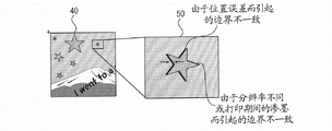
Figure 11 A and Figure 11 B illustrate for the processing of shrinking illustration pattern mask data.
With reference to figure 11B, by amplifying the illustration image that uses illustration pattern mask data 45 to extract from input area image 40, obtain image 50.
In input area image 40, the pixel of the boundary vicinity between reference picture and the illustration image comprises the information about reference picture and illustration image.Therefore, according to error degree, the difference between these images thickens, and perhaps may the border occur between these images inconsistent.In addition, if it is mutually different that the resolution of ink bleed or these images occurs during printing hand-written thin slice, then the border between these images may expand or dwindle, thereby so that the difference between these images thicken.In this case, as image 50, be difficult to suitably extract the illustration image.
Therefore, shown in Figure 11 A, shrink illustration pattern mask data.Particularly, in illustration pattern mask data 45, check the information of four neighbors of interested pixel.If the information of at least one pixel is 0 in these four neighbors, then the information of interested pixel is set to 0.If the information of all these four neighbors is 1, then the information of interested pixel is set to 1.By this being applied to whole illustration pattern mask data 45, the information that can shrink pixel is 1 zone, namely is used for extracting the zone of illustration image.
Alternatively, can shrink with the information of 8 neighbors of interested pixel.By increasing or reducing the number of times that shrinks, can adjust amount of contraction.
As mentioned above, by shrinking illustration pattern mask data, can shrink the zone that to extract.Therefore, in the input area image, can reduce the inconsistent impact of smeared out boundary and border between reference picture and the illustration image.
Figure 12 illustrates for by hand-written pattern mask data and illustration pattern mask data being synthesized to generate the example process (the step S108 of Fig. 4) of synthetic mask data.
If being arranged in one the value of pixel of the corresponding position of hand-written image mask data 42 and illustration pattern mask data 45 these two mask datas is 1, then the information corresponding with these pixels of this corresponding position is set to 1.Be 0 if be positioned at the value of pixel of the corresponding position of these two mask datas, then the information corresponding with these pixels of this corresponding position is set to 0.Thereby, generate synthetic mask data 47.
Figure 13 illustrates the example process of using synthetic mask data to extract image (the step S109 of Fig. 4) and image and the background image that extracts synthesized (the step S110 of Fig. 4) from the input area image.
At first, use synthetic mask data 47 from input area image 40, to extract image.
Particularly, if in synthetic mask data 47, the value that is arranged in the pixel of the position corresponding with the position of input area image 40 interested pixels is 1, then interested pixel is defined as the Pixel Information of input area image 40; Otherwise, if the value of the pixel in the above-mentioned synthetic mask data 47 is 0, then interested pixel in the input area image 40 is defined as the transparent information of input area image 40.Therefore, can from input area image 40, extract hand-written and illustration image 48.
Then, hand-written and illustration image 48 are synthesized to form synthetic result images 49 with background image 38.
The processing of Figure 13 comprises to be used by hand-written pattern mask data 42 and illustration pattern mask data 45 are synthesized formed synthetic mask data 47.Alternatively, can extract with hand-written image mask data 42 and illustration pattern mask data 45 respectively.
Although in Figure 13, after extracting hand-written and illustration image 48, carry out synthetic with background image 38, can be undertaken this by following processing and synthesize.
That is to say, extract image in order to use synthetic mask data 47 from input area image 40, if the value of interested pixel is 1 in the synthetic mask data 47, then use the respective pixel in the input area image 40.On the other hand, if the value of interested pixel is 0 in the synthetic mask data 47, then use the respective pixel in the background image 38.This processing is same so that can form synthetic result images 49.
In above-mentioned exemplary embodiments, when filling hand-written thin slice, the user can check between the image that will synthesize, and namely draws hand-written image during the position relationship between background image, illustration image and the hand-written image that will input.
In this exemplary embodiments, as described in reference Figure 10, separate with the mask data that is used for the extraction hand-written image, be used for extracting the mask data of illustration image according to the DID generation of illustration image.Therefore, regardless of employed color in the illustration image, can correctly extract the illustration image from the input area image.
Therefore, even when the scope of employed color in the scope of employed color in the illustration image and the reference picture is overlapping, also can extract the illustration image.
Therefore, each aspect of the present invention provides a kind of image processing equipment, this image processing equipment can allow user's hand-written text and drawing of input in hand-written thin slice when the position relationship that checks between background image and the still image, and can be from the correct image that extracts the zone corresponding with still image of the image of hand-written thin slice, and regardless of the color of still image how.
Replace generating as in the illustration pattern mask data described in this exemplary embodiments, can in advance the illustration pattern mask data corresponding with the illustration image being stored in the program storage 4.This can eliminate for the demand of carrying out generating for the DID according to the illustration image processing (the step S107 of Fig. 4) of the illustration pattern mask data that are used for extraction illustration image.Therefore, owing to become and can in the pixel data of illustration image, keep transparent information, thereby can expand the scope of spendable color in the illustration image.
Although in this exemplary embodiments, as the example of still image the illustration image has been described, the present invention is not limited to this.Can use any still image, as long as generate in advance this still image.The example of still image not only can comprise the illustration image, but also can comprise text image.
Although with reference to exemplary embodiments the present invention has been described, should be appreciated that, the present invention is not limited to disclosed exemplary embodiments.The scope of appended claims meets the widest explanation, to comprise all modifications, equivalent structure and function.
Claims (7)
1. image processing equipment, its output are by to background image with from synthesizing the image that forms by reading the zone of extracting the image that record sheet obtains, and described image processing equipment comprises:
Print unit is used for print image on record sheet;
Reading unit is used for reading record sheet;
Converting unit is used for converting described background image to reference picture, and the content of described reference picture is identical with the content of described background image, but the brightness of the described background image of brightness ratio of described reference picture is high;
Print control unit, be used for making described print unit that the first image is printed on record sheet as the input area that the user will write, described the first image is to be superimposed upon the composograph that forms on the described reference picture that is obtained by described converting unit by the still image that will be stored in the memory;
Extraction unit, be used for extracting the image that brightness is lower than the zone of predetermined threshold from the second image, described the second image is corresponding to read the described input area that comprises in the image that obtains when having the record sheet that has carried out the described input area that writes when described reading unit;
Acquiring unit, be used for by generating mask data based on described still image or passing through to select the mask data corresponding with described still image from described memory, obtain mask data, described mask data is used for determining described the second image zone corresponding with the described still image in being stored in described memory, and is used for extracting the image in the zone corresponding with described still image of determining from described the second image;
The second extraction unit, be used for by using the described mask data by described acquiring unit acquisition, determine in described the second image be stored in described memory in the corresponding zone of described still image, and from described the second image, extract and the regional corresponding described still image of determining; And
Output unit, be used for exporting following composograph, this composograph is to be superimposed upon the composograph that forms on the described background image by the described still image that the image that described extraction unit is extracted from described the second image and described the second extraction unit are extracted from described the second image by the described mask data of described acquiring unit acquisition by use.
2. image processing equipment according to claim 1, it is characterized in that, described extraction unit generates the second mask data, and use described the second mask data to extract image, described the second mask data is used for extracting the image that brightness is lower than the zone of described predetermined threshold from described the second image.
3. image processing equipment according to claim 2, it is characterized in that, described extraction unit and described the second extraction unit use by described the second mask data and the described mask data that obtained by described acquiring unit are synthesized the mask data that forms, from described the second image, extract the image that described still image and brightness are lower than the zone of described predetermined threshold, and
Wherein, described output unit is exported following composograph, and this composograph is to be superimposed upon the composograph that forms on the described background image by the image that the mask data that will use described mask data that described acquiring unit is obtained and described the second mask data to synthesize to form extracts.
4. image processing equipment according to claim 1 is characterized in that, also comprises be used to the described memory of storing described still image.
5. image processing equipment according to claim 1, it is characterized in that, described print control unit makes described print unit print position reference mark on record sheet, and described extraction unit extracts image from described the second image, wherein, cut out described the second image based on the described position reference mark that comprises in the image that when described reading unit reads record sheet, obtains.
6. image processing equipment according to claim 1 is characterized in that, described output unit is to described print unit output image, so that described print unit is printed described image.
7. image processing method is used for output by to background image with from synthesizing the image that forms by reading the zone that image that record sheet obtains extracts, and described image processing method comprises:
Convert described background image to reference picture, the content of described reference picture is identical with the content of described background image, but the brightness of the described background image of brightness ratio of described reference picture is high;
Export the first image to printing equipment, described the first image is to be superimposed upon the composograph that forms on the described reference picture by the still image that will be stored in the memory;
Described printing equipment is printed on the input area that described the first image will write as the user on the record sheet;
By generating mask data based on described still image or passing through from described memory, to select the mask data corresponding with described still image, obtain mask data, described mask data is used for determining the second image zone corresponding with the described still image in being stored in described memory, and be used for extracting the image in the zone corresponding with described still image of determining from described the second image, wherein said the second image is corresponding to read the described input area that comprises in the image that obtains when having the record sheet that has carried out the described input area that writes when reading device;
By use the described mask data that obtains determine in described the second image be stored in described memory in the corresponding zone of described still image; And
The composograph of output by forming on the background image as described in will being superimposed upon such as hypograph: brightness be lower than predetermined threshold and be included in as described in the image in zone in the second image; And the regional corresponding described still image that extracts from described the second image based on described mask data with determine.
Applications Claiming Priority (3)
| Application Number | Priority Date | Filing Date | Title |
|---|---|---|---|
| JP2008149363A JP5058887B2 (en) | 2008-06-06 | 2008-06-06 | Image processing apparatus, image processing method, and program |
| JP2008149363 | 2008-06-06 | ||
| JP2008-149363 | 2008-06-06 |
Publications (2)
| Publication Number | Publication Date |
|---|---|
| CN101600038A CN101600038A (en) | 2009-12-09 |
| CN101600038B true CN101600038B (en) | 2013-02-13 |
Family
ID=40966563
Family Applications (1)
| Application Number | Title | Priority Date | Filing Date |
|---|---|---|---|
| CN2009101469650A Expired - Fee Related CN101600038B (en) | 2008-06-06 | 2009-06-05 | Image processing apparatus and image processing method |
Country Status (5)
| Country | Link |
|---|---|
| US (1) | US8363260B2 (en) |
| EP (1) | EP2131566B1 (en) |
| JP (1) | JP5058887B2 (en) |
| KR (1) | KR101014673B1 (en) |
| CN (1) | CN101600038B (en) |
Families Citing this family (14)
| Publication number | Priority date | Publication date | Assignee | Title |
|---|---|---|---|---|
| JP5014284B2 (en) * | 2008-08-08 | 2012-08-29 | キヤノン株式会社 | Image processing apparatus, image processing method, and program |
| JP5075054B2 (en) * | 2008-08-08 | 2012-11-14 | キヤノン株式会社 | Image processing apparatus, image processing method, and program |
| FR2947082B1 (en) * | 2009-06-22 | 2014-12-12 | St Ericsson France Sas | METHOD AND DEVICE FOR PROCESSING A DIGITAL IMAGE TO LIGHTEN THIS IMAGE. |
| JP5540770B2 (en) * | 2009-07-30 | 2014-07-02 | 株式会社リコー | Image processing apparatus, image processing method, and image processing program |
| JP5451313B2 (en) * | 2009-10-27 | 2014-03-26 | キヤノン株式会社 | Image processing apparatus, image processing method, and program |
| US20110199624A1 (en) * | 2010-02-12 | 2011-08-18 | Kabushiki Kaisha Toshiba | Method and apparatus for processing image |
| JP5488082B2 (en) * | 2010-03-17 | 2014-05-14 | セイコーエプソン株式会社 | Information recognition system and control method thereof |
| CN102411458A (en) * | 2011-08-15 | 2012-04-11 | 留越 | Method and system for informatization processing of paper handwriting |
| JP6089406B2 (en) * | 2012-01-25 | 2017-03-08 | セイコーエプソン株式会社 | Image processing apparatus, printing apparatus, and image processing method |
| JP2015103919A (en) * | 2013-11-22 | 2015-06-04 | キヤノン株式会社 | Information processing device, system, method, and program |
| CN106339997B (en) * | 2015-07-09 | 2019-08-09 | 株式会社理光 | Image interfusion method, equipment and system |
| JP6931290B2 (en) * | 2017-03-03 | 2021-09-01 | キヤノン株式会社 | Image generator and its control method |
| CN107093199A (en) * | 2017-03-29 | 2017-08-25 | 阿里巴巴集团控股有限公司 | Method and device for generating clue figure |
| JP2022159844A (en) * | 2021-04-05 | 2022-10-18 | キヤノン株式会社 | IMAGE FORMING APPARATUS, CONTROL METHOD THEREOF, AND PROGRAM |
Citations (1)
| Publication number | Priority date | Publication date | Assignee | Title |
|---|---|---|---|---|
| CN1885899A (en) * | 2005-06-20 | 2006-12-27 | 佳能株式会社 | Image combining apparatus, and control method and program therefor |
Family Cites Families (20)
| Publication number | Priority date | Publication date | Assignee | Title |
|---|---|---|---|---|
| JPH04122991A (en) * | 1990-09-14 | 1992-04-23 | Hitachi Ltd | How to combine images and text |
| JPH05334413A (en) * | 1991-08-15 | 1993-12-17 | Fujitsu Ltd | Mask pattern creation system |
| JPH08204874A (en) * | 1995-01-30 | 1996-08-09 | Oki Electric Ind Co Ltd | Slip processing system by facsimile equipment |
| US6005972A (en) * | 1996-11-19 | 1999-12-21 | Eastman Kodak Company | Method for adding personalized text and/or graphics to composite digital image products |
| JP2000295565A (en) * | 1999-04-05 | 2000-10-20 | Olympus Optical Co Ltd | Image forming device |
| US7606819B2 (en) * | 2001-10-15 | 2009-10-20 | Maya-Systems Inc. | Multi-dimensional locating system and method |
| JP3856211B2 (en) * | 2001-12-14 | 2006-12-13 | オムロンエンタテインメント株式会社 | Image printing apparatus and method, and program |
| JP4203808B2 (en) * | 2003-10-08 | 2009-01-07 | 富士フイルム株式会社 | Image processing device |
| US20050213174A1 (en) * | 2004-02-27 | 2005-09-29 | Seiko Epson Corporation | Image processing system and image processing method |
| US8023145B2 (en) * | 2004-02-27 | 2011-09-20 | Seiko Epson Corporation | Image processing system and image processing method |
| JP2006023798A (en) * | 2004-07-06 | 2006-01-26 | Fuji Photo Film Co Ltd | Image data processor, image data processing method, and image data processing program |
| JP4417292B2 (en) * | 2005-05-25 | 2010-02-17 | ソフトバンクモバイル株式会社 | Object output method and information processing apparatus |
| JP4683628B2 (en) * | 2005-06-24 | 2011-05-18 | キヤノン株式会社 | Image processing apparatus, image processing method, and program |
| JP2007013235A (en) * | 2005-06-28 | 2007-01-18 | Canon Inc | Image compositing apparatus, control method and program of image processor |
| JP4926589B2 (en) * | 2005-09-30 | 2012-05-09 | キヤノン株式会社 | Image composition apparatus, image composition method, and program |
| US7769245B2 (en) * | 2005-09-30 | 2010-08-03 | Canon Kabushiki Kaisha | Image combining apparatus and control method for the same |
| JP4587180B2 (en) * | 2005-09-30 | 2010-11-24 | キヤノン株式会社 | Image processing apparatus, image processing method, and program |
| JP4757131B2 (en) | 2006-07-24 | 2011-08-24 | キヤノン株式会社 | Image composition apparatus, image composition method, and program |
| JP2008103987A (en) * | 2006-10-19 | 2008-05-01 | Murata Mach Ltd | Image processor |
| US8625113B2 (en) * | 2010-09-24 | 2014-01-07 | Ricoh Company Ltd | System and method for distributed optical character recognition processing |
-
2008
- 2008-06-06 JP JP2008149363A patent/JP5058887B2/en not_active Expired - Fee Related
-
2009
- 2009-05-26 EP EP09007005.3A patent/EP2131566B1/en not_active Not-in-force
- 2009-06-04 KR KR1020090049344A patent/KR101014673B1/en active IP Right Grant
- 2009-06-04 US US12/478,469 patent/US8363260B2/en not_active Expired - Fee Related
- 2009-06-05 CN CN2009101469650A patent/CN101600038B/en not_active Expired - Fee Related
Patent Citations (1)
| Publication number | Priority date | Publication date | Assignee | Title |
|---|---|---|---|---|
| CN1885899A (en) * | 2005-06-20 | 2006-12-27 | 佳能株式会社 | Image combining apparatus, and control method and program therefor |
Also Published As
| Publication number | Publication date |
|---|---|
| EP2131566A2 (en) | 2009-12-09 |
| US8363260B2 (en) | 2013-01-29 |
| US20090303544A1 (en) | 2009-12-10 |
| CN101600038A (en) | 2009-12-09 |
| JP2009296439A (en) | 2009-12-17 |
| KR101014673B1 (en) | 2011-02-16 |
| EP2131566B1 (en) | 2013-05-08 |
| KR20090127226A (en) | 2009-12-10 |
| EP2131566A3 (en) | 2010-09-01 |
| JP5058887B2 (en) | 2012-10-24 |
Similar Documents
| Publication | Publication Date | Title |
|---|---|---|
| CN101600038B (en) | Image processing apparatus and image processing method | |
| JP5014284B2 (en) | Image processing apparatus, image processing method, and program | |
| US8782506B2 (en) | Method and apparatus for creating album, and recording medium | |
| JP4344925B2 (en) | Image processing apparatus, image processing method, and printing system | |
| RU2369034C2 (en) | Image combination device, method and programm of it's managing | |
| US8169652B2 (en) | Album creating system, album creating method and creating program with image layout characteristics | |
| US8041149B2 (en) | Image processing apparatus, and control method and program of the same | |
| JP2008036856A (en) | Printing apparatus and printing method | |
| WO2006013956A1 (en) | Image processing system and image processing method | |
| US20040257625A1 (en) | Apparatus for, method of, and system for image processing | |
| JP4926589B2 (en) | Image composition apparatus, image composition method, and program | |
| JP4948069B2 (en) | Image processing apparatus, image processing method, and program | |
| JP4710672B2 (en) | Character color discrimination device, character color discrimination method, and computer program | |
| JP3970465B2 (en) | Image output method and apparatus, and recording medium | |
| JP4690676B2 (en) | Image processing system, image processing method, and image processing program | |
| CN100511267C (en) | Graph and text image processing equipment and image processing method thereof | |
| JP4674123B2 (en) | Image processing system and image processing method | |
| JP3778293B2 (en) | Image processing system and image processing method | |
| JP2005301337A (en) | Apparatus and method for image processing, and program | |
| JP4582247B2 (en) | Image processing system, image processing method, and image processing program | |
| US20090037475A1 (en) | Image Processing Device, Image Processing Method, and Image Processing Program | |
| JP2004312487A (en) | Image recorder, image recording method and storage medium | |
| JP2004114485A (en) | Printing equipment |
Legal Events
| Date | Code | Title | Description |
|---|---|---|---|
| C06 | Publication | ||
| PB01 | Publication | ||
| C10 | Entry into substantive examination | ||
| SE01 | Entry into force of request for substantive examination | ||
| C14 | Grant of patent or utility model | ||
| GR01 | Patent grant | ||
| CF01 | Termination of patent right due to non-payment of annual fee | ||
| CF01 | Termination of patent right due to non-payment of annual fee |
Granted publication date: 20130213 Termination date: 20200605 |