CN101593350B - Depth adaptive video-splicing method, device and system thereof - Google Patents
Depth adaptive video-splicing method, device and system thereof Download PDFInfo
- Publication number
- CN101593350B CN101593350B CN 200810099871 CN200810099871A CN101593350B CN 101593350 B CN101593350 B CN 101593350B CN 200810099871 CN200810099871 CN 200810099871 CN 200810099871 A CN200810099871 A CN 200810099871A CN 101593350 B CN101593350 B CN 101593350B
- Authority
- CN
- China
- Prior art keywords
- offset value
- pixel
- epipolar
- transformation
- video
- Prior art date
- Legal status (The legal status is an assumption and is not a legal conclusion. Google has not performed a legal analysis and makes no representation as to the accuracy of the status listed.)
- Expired - Fee Related
Links
- 238000000034 method Methods 0.000 title claims abstract description 69
- 230000003044 adaptive effect Effects 0.000 title abstract description 5
- 230000009466 transformation Effects 0.000 claims description 218
- 238000012935 Averaging Methods 0.000 claims description 12
- 238000002156 mixing Methods 0.000 description 21
- 230000008569 process Effects 0.000 description 15
- 238000004422 calculation algorithm Methods 0.000 description 13
- 238000004364 calculation method Methods 0.000 description 12
- 238000005516 engineering process Methods 0.000 description 11
- 238000000844 transformation Methods 0.000 description 11
- 230000000007 visual effect Effects 0.000 description 11
- 238000010586 diagram Methods 0.000 description 9
- 239000011159 matrix material Substances 0.000 description 6
- 238000012545 processing Methods 0.000 description 5
- 239000013598 vector Substances 0.000 description 5
- 238000007792 addition Methods 0.000 description 4
- 230000008901 benefit Effects 0.000 description 4
- 230000008859 change Effects 0.000 description 3
- 238000013507 mapping Methods 0.000 description 2
- 238000005457 optimization Methods 0.000 description 2
- 238000012952 Resampling Methods 0.000 description 1
- 238000013459 approach Methods 0.000 description 1
- 238000006243 chemical reaction Methods 0.000 description 1
- 230000002354 daily effect Effects 0.000 description 1
- 238000011161 development Methods 0.000 description 1
- 230000000694 effects Effects 0.000 description 1
- 230000003203 everyday effect Effects 0.000 description 1
- 238000005286 illumination Methods 0.000 description 1
- 230000006872 improvement Effects 0.000 description 1
- 238000012986 modification Methods 0.000 description 1
- 230000004048 modification Effects 0.000 description 1
- 238000012544 monitoring process Methods 0.000 description 1
- 230000008447 perception Effects 0.000 description 1
- 238000007781 pre-processing Methods 0.000 description 1
- 230000003252 repetitive effect Effects 0.000 description 1
- 230000001131 transforming effect Effects 0.000 description 1
Images


Landscapes
- Image Processing (AREA)
Abstract
The invention relates to a depth adaptive video-splicing method, a device and a system thereof. The depth adaptive video-splicing system comprises a camera array, a calibration device, a video-splicing device, a pixel interpolation device and a mixer, wherein a plurality of source videos are generated by the camera array; the calibration device executes antipodal calibration and camera position calibration, confirms a splicing area in each special adjacent image pair in a plurality of source videos and generates a pixel index table; the video-splicing device calculates an average pixel deviation value corresponding to the depth, forms a compensation item of the pixel index table based on the average pixel deviation value and compensates the pixel index table by the compensation item; and the pixel interpolation device and the mixer use the upgraded pixel index table and generate a panoramic video according to a plurality of source videos.
Description
Technical Field
The present invention relates to the field of computer vision, and more particularly, to a method, apparatus, and system for depth adaptive video stitching.
Background
The technology of aligning and stitching images into seamless photomosaic maps was the earliest and most widely used technology in the field of computer vision. This technique generates high resolution photographs that have been used to produce digital maps and satellite photographs. Image stitching techniques are also currently implemented and embedded in digital cameras to obtain ultra-wide angle photographs.
The video stitching technique is a special image stitching technique that provides wide-angle, high-resolution frame stitching images from different video sources. With the rapid development of the display industry, very high resolution displays are moving into people's daily lives. There is a need for high resolution and wide angle video in consumer electronics. Video stitching technology may be one solution to create high resolution and wide angle video for different high definition needs. In addition, the video splicing technology is a powerful tool for large-range and large-coverage visual monitoring, such as supermarkets, long streets, large buildings and the like. These locations typically have a large surveillance area and cannot be monitored by a single camera. In addition, people may prefer to see wide-angle video in a video conference, which conforms to the everyday perception of humans.
While current image stitching techniques are capable of producing panoramic video frame-by-frame, such techniques typically require a high computational burden and are not suitable for real-time video stitching applications.
The video splicing technology combines a plurality of source video streams into a high-resolution wide-angle panoramic video in real time. Since visual quality and computational burden are two aspects of a problem, video stitching techniques need to provide good video quality and speed. A panoramic video of poor visual quality has ghosting in its frames, such as noticeable seams, ghosting effects, erroneous image alignment, and the like. Some ghosting is due to inaccurate image alignment, color inconsistencies, motion blur. Other ghosting is caused by parallax problems. More accurate calculation algorithms and appropriate pre-processing can improve visual quality associated with inaccurate image alignment and color inconsistency problems. Accurate geometry estimation may reduce ghosting caused by parallax problems. However, such a strategy typically requires more computation.
In general, a video stitching algorithm can be considered as a repetitive image stitching process (see reference [1 ]). The algorithm typically has two steps. In a first step, video frames are extracted from different source video streams and stored in memory. In a second step, the stored frames are input into an image stitching unit to generate a frame stitching map. The image stitching unit first performs frame alignment. The projective transformation for each frame is estimated according to a pixel-based alignment technique or a feature-based alignment technique. From the estimated projective transformation, the image pixels can be mapped onto the reference image plane. This reference image plane is also the image plane of the final frame-stitched image. Finally, the stitching is completed while mapping the source video frame pixels to the reference plane. If a pixel in the frame-spliced picture has several corresponding pixels, a pixel blending process is required.
However, simply employing image stitching techniques in video stitching algorithms is not an effective strategy. Because the image alignment process is extremely time consuming, such video stitching algorithms do not work in real-time or near real-time. One simple way to accelerate the video stitching algorithm is to use historical information (see reference [2 ]). The image alignment parameters are initially calculated once. In the next stitching, the frame stitching of the subsequent frame may use previously calculated image alignment parameters. The strategy reduces the image alignment calculation time of continuous frames and can ensure the real-time work of a video stitching algorithm. This algorithm is suitable for fixed position cameras with long range or constant depth of field.
Since many videos are compressed, the video stitching algorithm can use motion compensation information (see reference [3 ]). The motion vectors of a macroblock typically have block-based matching information. This information can provide coarse information and can be used to iteratively update the geometric transformation computation. To improve the accuracy of the geometric transformation estimation, additional matching and global motion estimation are still required. Such an algorithm reduces the computation time for feature matching during image alignment.
Disclosure of Invention
The current solution to video stitching has the problem that a good balance between speed and visual quality cannot be found.
The video stitching technology based on the image stitching technology has the best visual quality but the most calculation time. In addition, projective transformation estimation is usually implemented by some probability optimization techniques, and it is not easy to obtain stable estimation results.
The video splicing technology based on the historical information is fast and convenient, and has good visual quality for certain specific scenes. The technology is suitable for occasions with fixed cameras and unchanged depth of field. However, once the depth of field changes, e.g., foreground objects move far or close, ghosting will occur. Ghosting may appear as repeating regions or as partial objects. Ghosting is mainly caused by parallax problems.
Video stitching techniques based on pre-computed matching information work quickly and can have acceptable visual quality. This is because the image alignment techniques employed are often not sufficiently accurate. The motion vectors extracted from the compressed video stream are very noisy and the matching accuracy is limited. While this technique may employ some refinement, the alignment is not accurate enough since the blocks are typically matched with half-pixel precision. Furthermore, refinement of block matching and motion estimation will take extra computational time.
The invention provides a technology for fast and high-visual-quality video splicing. The present invention aims to provide a fast geometry estimation using a simple depth compensation strategy. The stitching method of the invention first calculates projective transformation for each pair of source videos in a camera position calibration step. Then, an accurate projective transformation of each source video is obtained according to the simple depth compensation process. In addition, a pixel indexing scheme is designed and adopted to speed up pixel projection. Using the above optimization strategy, the technique of the present invention can work quickly and greatly reduce ghosting caused by parallax problems.
The basic idea of the invention is that: based on the simple depth of field estimation process, a projective transformation is estimated. In this way, image alignment is no longer based on feature matching and parameter estimation processes. On the other hand, the present invention can easily index the projective transformation of pixels, which also speeds up the image blending process.
According to a first aspect of the present invention, there is provided a method of determining a depth compensation term in a video splicing application, comprising the steps of: calculating an offset value for each corresponding point pair at a seam region within two spatially adjacent images in a plurality of source videos; averaging the offset values of all corresponding point pairs at the seam area in the two spatially adjacent images to obtain an average offset value of the pair of spatially adjacent images; and calculating a depth compensation term by using the epipolar transform parameter, the projective transform parameter, and the average offset value of all pairs of spatially neighboring images. The depth compensation term is calculated by multiplying the epipolar transform parameter with the projective transform parameter to generate a desired epipolar projective transform product, and by multiplying the desired epipolar projective transform product with the average offset value for all spatially adjacent image pairs.
Preferably, the method for determining a depth compensation term in a video splicing application further comprises the following steps before the offset value calculating step: epipolar transformation parameters and projective transformation parameters are generated.
Preferably, the offset value of each corresponding point pair at the seam area is calculated as follows: calculating the sum of the square brightness differences of the image corresponding to each offset value in the preset offset value range; searching for a sum of least squared luminance differences among the calculated sums of luminance differences corresponding to all offset values in the predetermined offset value range; and determining an offset value corresponding to the sum of the least square luminance differences as an offset value for the corresponding point pair.
According to a second aspect of the present invention, there is provided an apparatus for determining a depth compensation term in a video splicing application, comprising: means for calculating an offset value for each corresponding point pair at a seam region within two spatially adjacent images in a plurality of source videos; means for averaging the offset values of all corresponding point pairs at the seam area within the two spatially adjacent images to obtain an average offset value for the pair of spatially adjacent images; and means for calculating a depth compensation term by using the epipolar transform parameter, the projective transform parameter, and the average offset value of all spatially neighboring image pairs. The means for calculating the depth compensation term generates a desired antipodal projective transformation product by multiplying the antipodal transformation parameter with the projective transformation parameter, and calculates the depth compensation term by multiplying the desired antipodal projective transformation product with the average offset value for all spatially adjacent image pairs.
According to a third aspect of the present invention, there is provided a video splicing apparatus comprising: an offset value calculator for calculating an offset value for each corresponding point pair at the seam area within two spatially adjacent images in the plurality of source videos, and averaging the offset values of all corresponding point pairs at the seam area within the two spatially adjacent images to obtain an average offset value for the pair of spatially adjacent images; a compensation calculator for calculating a compensation item of the pixel index table by using the epipolar transformation parameter, the projective transformation parameter, and an average offset value of all the spatially neighboring image pairs generated by the offset value calculator; and the index updater is used for updating the pixel corresponding relation and the weight thereof in the pixel index table by the compensation item calculated by the compensation calculator so as to obtain an updated pixel index table. The epipolar transform parameter, the projective transform parameter, and the pixel index table are externally generated, and then a desired epipolar projective transform product is externally generated by multiplying the epipolar transform parameter with the projective transform parameter, and the compensation calculator calculates a compensation term of the pixel index table by multiplying the desired epipolar projective transform product with an average offset value of all spatially neighboring image pairs.
Preferably, the updated pixel index table is used externally to generate a panoramic video from the plurality of source videos.
Preferably, the offset value calculator calculates the offset value for each corresponding point pair at the seam area by: calculating the sum of the square brightness differences of the image corresponding to each offset value in the preset offset value range; searching for a sum of least squared luminance differences among the calculated sums of luminance differences corresponding to all offset values in the predetermined offset value range; and determining an offset value corresponding to the sum of the least square luminance differences as an offset value for the corresponding point pair.
Preferably, the index table includes pixel position correspondence and weights.
According to a fourth aspect of the present invention, there is provided a video stitching system comprising: a video splicing apparatus according to the third aspect of the present invention; and a pixel interpolator and mixer for generating a panoramic video from the plurality of source videos by using the updated pixel index table from the video stitching device.
Preferably, the video stitching system further comprises: and the calibration device is used for generating the epipolar transformation parameters, the projective transformation parameters, the pixel index table and the required epipolar projective transformation product.
Preferably, the calibration device comprises: the antipodal calibrator is used for calculating and storing antipodal transformation parameters; the camera position calibrator is used for calculating and storing projection transformation parameters; a multiplier for multiplying the epipolar transform parameter by the projective transform parameter to generate a desired epipolar projective transform product; a seam determiner for determining a seam region and weights of pixels at the seam region based on epipolar transformation parameters and projective transformation parameters from the epipolar calibrator and the camera position calibrator, respectively; and an index generator for generating a pixel index table based on the projective transformation parameters from the camera position calibrator and the seam region and pixel weights from the seam determiner.
Preferably, the video stitching system further comprises: a camera array for generating the plurality of source videos, wherein at least two cameras in the camera array are spatially arranged with overlapping fields of view.
According to a fifth aspect of the present invention, there is provided a video splicing method, comprising the steps of: calculating an offset value for each corresponding point pair at a seam region within two spatially adjacent images in a plurality of source videos; averaging the offset values of all corresponding point pairs at the seam area in the two spatially adjacent images to obtain an average offset value of the pair of spatially adjacent images; calculating a compensation term of the pixel index table by using the epipolar transformation parameter, the projective transformation parameter, and the average offset value of all pairs of spatially adjacent images; and updating the pixel corresponding relation and the weight thereof in the pixel index table by the calculated compensation item to obtain an updated pixel index table. A compensation term of the pixel index table is computed by externally generating a desired epipolar projective transformation product by multiplying the epipolar transformation parameter with the projective transformation parameter, and by multiplying the desired epipolar projective transformation product with the average offset value of all spatially neighboring image pairs.
Preferably, the video splicing method further comprises the following steps: using the updated pixel index table to generate a panoramic video from the plurality of source videos.
Preferably, the offset value for each corresponding point pair at the seam area is calculated by: calculating the sum of the squared luminance differences corresponding to each offset value in a predetermined range of offset values; searching for a sum of least squared luminance differences among the calculated sums of luminance differences corresponding to all offset values in the predetermined offset value range; and determining an offset value corresponding to the sum of the least square luminance differences as an offset value for the corresponding point pair.
Preferably, the index table includes pixel position correspondence and weights.
According to a sixth aspect of the present invention, there is provided a video splicing apparatus comprising: an offset value calculator for calculating an offset value for each corresponding point pair at the seam area within two spatially adjacent images in the plurality of source videos, and averaging the offset values of all corresponding point pairs at the seam area within the two spatially adjacent images to obtain an average offset value for the pair of spatially adjacent images; a compensation calculator for calculating a compensation term for the pixel transformation by using the epipolar transformation parameter, the projective transformation parameter, and the average offset value of all spatially neighboring image pairs generated by the offset value calculator; and a correspondence calculator for calculating a positional correspondence between points within the two spatially adjacent images and their corresponding target points by using the epipolar transformation parameter, the projective transformation parameter, and the compensation term calculated by the compensation calculator to generate a pixel transformation correspondence including the calculated positional correspondence and an externally provided weight. The compensation calculator calculates a compensation term for the pixel by: generating a required epipolar projective transformation product by multiplying the epipolar transformation parameter by the projective transformation parameter; and multiplying the desired antipodal projective transformation product by the average offset value of all spatially neighboring image pairs.
Preferably, the generated pixel transformation correspondences are externally used to generate a panoramic video from the plurality of source videos.
Preferably, the epipolar transform parameters and the projective transform parameters are generated externally.
Preferably, the offset value calculator calculates the offset value for each corresponding point pair at the seam area by: calculating the sum of the square brightness differences of the image corresponding to each offset value in the preset offset value range; searching for a sum of least squared luminance differences among the calculated sums of luminance differences corresponding to all offset values in the predetermined offset value range; and determining an offset value corresponding to the sum of the least square luminance differences as an offset value for the corresponding point pair.
According to a seventh aspect of the present invention, there is provided a video stitching system comprising: a video splicing apparatus according to a sixth aspect of the present invention; and a pixel interpolator and mixer for generating a panoramic video from the plurality of source videos by using the calculated pixel transformation correspondences from the video stitching device.
Preferably, the video stitching system further comprises: and the calibration device is used for generating the epipolar transformation parameters, the projective transformation parameters, the seam area and the weight of the pixel at the seam area.
Preferably, the calibration device comprises: the antipodal calibrator is used for calculating and storing antipodal transformation parameters; the camera position calibrator is used for calculating and storing projection transformation parameters; and a seam determiner for determining a seam region and weights of pixels at the seam region based on the epipolar transformation parameters and projective transformation parameters from the epipolar calibrator and the camera position calibrator, respectively.
Preferably, the video stitching system further comprises: a camera array for generating the plurality of source videos, wherein at least two cameras in the camera array are spatially arranged with overlapping fields of view.
According to an eighth aspect of the present invention, there is provided a video splicing method, comprising the steps of: calculating an offset value for each corresponding point pair at a seam region within two spatially adjacent images in a plurality of source videos; averaging the offset values of all corresponding point pairs at the seam area in the two spatially adjacent images to obtain an average offset value of the pair of spatially adjacent images; calculating a compensation term for the pixel transformation by using the epipolar transformation parameter, the projective transformation parameter, and the average offset value of all pairs of spatially adjacent images; and calculating a positional correspondence between points within the two spatially neighboring images and their corresponding target points by using the epipolar transformation parameters, the projective transformation parameters, and the calculated compensation terms to generate a pixel transformation correspondence, the pixel transformation correspondence including the calculated positional correspondence and an externally provided weight. The compensation term for the pixel transform is calculated by: generating a required epipolar projective transformation product by multiplying the epipolar transformation parameter by the projective transformation parameter; and multiplying the desired antipodal projective transformation product by the average offset value of all spatially neighboring image pairs.
Preferably, the video splicing method further comprises the following steps: generating a panoramic video from the plurality of source videos using the generated pixel transformation correspondences.
Preferably, the video stitching method further comprises the following steps before the step of calculating the offset value: and generating epipolar transformation parameters, projective transformation parameters, a seam region and the weight of the pixel at the seam region.
Preferably, the offset value for each corresponding point pair at the seam area is calculated by: calculating the sum of the square brightness differences of the image corresponding to each offset value in the preset offset value range; searching for a sum of least squared luminance differences among the calculated sums of luminance differences corresponding to all offset values in the predetermined offset value range; and determining an offset value corresponding to the sum of the least square luminance differences as an offset value for the corresponding point pair.
The present invention makes two contributions. The first contribution is a fast image alignment technique that uses simple depth of field compensation to estimate the current projective transformation. The second contribution is to index the projective transformation.
The video splicing method comprises the following steps: camera position calibration, camera epipolar calibration, simple depth estimation, projective transformation update, and pixel interpolation and blending. The video stitching system according to the invention accordingly comprises: the system comprises a camera position calibration unit, a camera epipolar calibration unit, a simple depth estimation unit, a projective transformation updating unit and a pixel interpolation and mixing unit. The camera position calibration unit and the camera epipolar calibration unit perform system initialization at the start. These two processes performed by the two respective units obtain the projective transformation to be used in the splicing of successive frames.
After initialization, successive video frames are stitched. First, the source video frame is calibrated by using the epipolar transform estimated in a simple depth estimation unit. Then, by the block matching process, an average offset value near the seam in the overlapping region of the two calibration frames is obtained. Based on the estimated offset value, the pre-calculated projective transformation parameters are updated accordingly by the projective transformation updating unit. The pixel index unit transforms the new projective transformation for stitching into a pixel index. While the mixing weights are calculated. Finally, pixels in the frame mosaic are interpolated and/or blended from the source video pixels by a pixel interpolation and blending unit.
The present invention has two advantages. The first advantage is that the visual quality of the panoramic video is good. The technique of the present invention can obtain accurate projective transformation frame by frame. By the depth compensation strategy of the invention, the ghost image caused by the change of the depth of field is reduced. A second advantage is that the solution of the invention is fast and suitable for real-time applications. The projective transformation updating method is simple and effective. The transform index method is also efficient and can save a large amount of floating point computation time.
Drawings
The above and other objects, features and advantages of the present invention will become more apparent from the following detailed description of non-limiting embodiments thereof, when taken in conjunction with the accompanying drawings, wherein:
FIG. 1 is a block diagram of a video stitching system according to a first embodiment of the present invention;
FIGS. 2(a), 2(b) and 2(c) are schematic diagrams illustrating examples of projective transformations;
FIG. 3 is a schematic diagram illustrating the transformation of a pair of spatially adjacent images;
FIG. 4 is a schematic diagram illustrating the topology of three spatially adjacent images;
FIG. 5 is a flow chart of a video stitching method according to a first embodiment of the present invention;
FIG. 6 is a block diagram of a video stitching system according to a second embodiment of the present invention;
FIG. 7 is a flow chart of a video stitching method according to a second embodiment of the present invention;
FIGS. 8(a) and 8(b) show a pair of original images with two images spatially adjacent;
FIG. 9 shows a prior art stitched panoramic result of the two images shown in FIGS. 8(a) and 8 (b); and
fig. 10 shows the stitched panoramic results of the present invention for the two images shown in fig. 8(a) and 8 (b).
Detailed Description
The invention will be described below with reference to the accompanying drawings. In the following description, some specific embodiments are for illustrative purposes only and should not be construed as limiting the present invention in any way, but merely as exemplifications thereof. Although it may be possible to obscure the understanding of the present invention, the conventional structure or configuration will be omitted.
The invention combines a plurality of input source video streams into a high-resolution and wide-angle video stream in real time. The video stitching system of the present invention has two devices. The first means is a calibration means 200, which calibration means 200 calculates the projective transformation at the beginning. The second means is a splicing means 300, which splicing means 300 splices different source video frames frame by frame into a frame-spliced graph. Fig. 1 shows a block diagram of the system.
1. Calibration
The task of calibration is to obtain the projective transformation, determine the seam, and generate the index table. Since this processing is performed at the time of system initialization, no particular limitation is imposed on the time. By this processing, three kinds of projective transformations are obtained.


The above three projective transformations are referred to as adjacent projective transformation, epipolar calibration transformation, and reference projective transformation, respectively.
Fig. 2(a) -2 (c) show illustrations of these three transformations. FIG. 2(a) shows a neighboring transformation H mapping an image j to an image iij. FIG. 2(b) shows the antipodal calibration transformation, respectively AndOiand OjIs the image center of the calibrated image. Fig. 2(c) shows a reference projective transformation. If an image plane is selected as the reference plane, a reference projective transformation is derived from neighboring transformations according to the topology of the source video.
To obtain the above transformation, feature-based image alignment techniques may be employed. First, feature points are detected for each frame using a feature point detector such as a SIFT detector, a Haris detector (see references [4] and [5 ]). Then, each feature point is represented as a feature vector according to its local texture by a feature point descriptor (SIFT descriptor). Feature matching is performed between the two frames based on the feature vectors to calculate an image correspondence. Once enough pairs of matching feature points are obtained, the locations of all matching feature points are used to estimate the neighboring projective transforms. If there are not enough pairs of matching feature points, the two frames are labeled as non-adjacent pairs. On the other hand, the fundamental matrix may also be estimated based on the matching feature points. Such transformation parameter estimates may be obtained by parameter estimation techniques such as the RANSAC algorithm (see reference [6 ]). The epipolar calibration transform can be easily derived by a resampling algorithm (see reference [6]) based on the basis of the fundamental matrix. In general, the image plane of the center image is selected as the reference plane according to the obtained connection relationship of the adjacent image pairs. Thus, by a corresponding multiplication of adjacent projective transforms, a reference projective transform may be obtained.
After the transformation estimation, the obtained transformation parameters are stored in a memory and the topology of the source video is stored for further use. Since initialization does not affect the computational burden of successive frame splicing, the transform estimation process can select a time-consuming algorithm to ensure accuracy.
Referring to FIG. 3, there is shown neighboring projective transforms HijAnd antipodal calibration transformation Andfor a pair of images, once the adjacent projective transformation and epipolar transformation parameters are estimated, the seam of the two images is easily determined. First, an image center (O)j) Projected to the center of the image as OiOf the other image. Then, using the epipolar transformation of another image, a new image center is madeAnd then projecting. O isjIs marked as Oj'. Center of another image OiProjection to O with the same antipodal transformationi'. In the calibration image plane of the other image, the seam is the calibration image center Oi' and Oj' middle region in between, and the seam region width w is pre-specified by the user or system. And obtaining the mixing weight of the seam pixels according to the distance between each seam pixel in the calibration image coordinates and the center of the corresponding image. For seam pixel k, the blending weight is calculated as follows:
wherein, distk(i) Is the distance between the seam pixel k and the center of its corresponding image i. The denominator is the sum of the distances between pixel k and its corresponding image center.
Once the different transformation parameters are estimated, the positional correspondence between the target pixel position (x ', y') and the source pixel position (x, y) can be calculated and a projection index table established by:
wherein, a (a)11,a12,a13,a31,a32,a21,a22,a23) Are projective transformation parameters. The index table has four columns and will be described with reference to table 1 below. The first column is the pixel location in the frame-stitched image. The second column is the corresponding pixel location in the source video frame. The third column is the source video number of the source pixel. The last column is the pixel weights used in blending.
2. Splicing
The task of stitching is to build a panoramic video frame by frame. As is well known, typical image stitching includes image alignment and image blending. The video stitching scheme of the invention provides a fast projective transformation updating method and a pixel index technology to accelerate the stitching processing with high visual quality. The inventive approach first estimates the depth of field using a simple depth estimation method. Based on the estimated depth, the reference projection is modified accordingly. The associated pixel index is updated with the new reference projection. Finally, pixel interpolation and blending processes are employed to produce a frame-stitched image. In the following subsections, depth estimation, projective transformation update, transformation index update, and pixel interpolation and blending processes will be described in detail.
2.1 depth estimation
The goal of depth estimation is to obtain depth of field information. In addition, the inventive solution focuses only on depth changes in the overlap region of adjacent image pairs. This is because if the current depth of field is different from the initialized depth of field, a change in depth of field will cause ghosting. Due to the different depths of field, the neighboring projective transformation and the reference projective transformation change. Therefore, the video stitching scheme needs to estimate the current depth field and compensate for the offset value. From a computational point of view, the pixel offset value is synonymous with depth, since in world coordinates the pixel offset value is proportional to the object depth. Using an epipolar projective transform, the source video frames can be aligned horizontally to the epipolar line. The offset value for a pixel is only the x value in the calibration image coordinates. The estimation of the offset values is affected by illumination changes, occlusion and aperture problems. Therefore, it is impossible to obtain an accurate offset value for each pixel. On the other hand, obtaining the offset value for each pixel is a time consuming task. Therefore, the scheme of the invention only selects some characteristic points near the seam area for depth estimation. In this embodiment, a column of pixels near the seam is selected as the feature point to estimate their offset values. Once the offset value calculation is completed for this column of pixels, the average of the offset values is calculated as the estimated image offset value. The idea of this strategy is: only the domain offset value is calculated to represent the depth of field. The inventive strategy is simple and effective, since the main objects usually attract human attention, while ghosting only appears in overlapping image areas, especially in seam areas. The offset value estimation for the column pixels is by means of a block matching based squared difference measure method. The scene offset value estimation method is described below:
for each pair of calibrated adjacent images Andthe subscript t denotes the time instant, the superscript c denotes that epipolar calibration has been performed, the superscripts i and j denote (spatially adjacent) image positions:
1) based on the initial information, determining Middle SjAnd
 middle SjThe position of the joint at (a).
2) For theMiddle row of Where w represents the width of the seam,
(1) the variable D is changed from-D to + D, where D is pre-specified by the user of the system as a range of predetermined offset values.
The sum of the squared luminance differences is calculated as follows:
(2) the offset values for pixel k are: dk=arg min(diff(d))
3) Calculating an offset value for the pair of images Where N is the number of pixels in the image column.
2.2 projective transformation update
Once the scheme of the present invention obtains the offset values for a pair of adjacent imagesNew neighboring projective transforms can be easily calculated. In the present invention, a homographic transform using a 3 × 3 floating-point matrix is selected to represent the projective transform.
Referring again to FIG. 3, the neighboring projective transforms H are shownijAnd antipodal calibration transformation And
And let us assume vector XiWith (x, y) representing the pixel position in the source image i. Xj、
 Andrepresenting the pixel positions in the source image j and the calibration images i and j. Transforming H in adjacent projectionsijNext, the pixel in image j can be transformed into image i with new position X'j. Figure 2 also shows the position of the seam in the reference plane and the epipolar calibrated image coordinates of image i. This indicates that the same seam has different position representations in different image coordinates.
If the plane of image i is selected as the reference plane, the positional transformation of the neighboring projective transformations can be expressed as follows:
Xji(t)=Hji(t)Xj(3)
where t represents the time of the source video. At the same time, images i and j may be calibrated by an epipolar calibration transform. This transformation may also be for Xji(t) is carried out. Since the same seam can be represented in the image coordinates of image i and its calibration image, the seam in the calibration image coordinates is vertical. The calibration image position for image j is represented as follows:
combining equations 3 and 4 yields:
this equation means that image j is first projected onto the plane of image i. It is then projected onto the calibration image plane of image i. If the depth of field changes at time t +1, the offset value can be estimated by the aforementioned depth estimation process Because of the fact that
 Can be set to 0, so the offset value can be expressed as:
from equation 6, the following offset value representation can be obtained:
if it hasThe matrix inverse of (c), equation 7 can be expressed as:
from equation 8, it is clear that the pixel projection of image j onto the reference plane can be divided into two parts. The first part is by using HjiThis is obtained in the calibration device. The other part is a compensation term, determined by the estimated offset value and the antipodal calibration transform.
However, it is an object of the present invention to obtain a current reference projective transformation. Fig. 4 shows a topological relationship diagram of three images.
Based on equation 8, image k may be projected to image j as follows:
thus, image k may first be projected to image j. The transformed image k is then projected to image i as follows:
from equation 10, it is clear that all the used transformations have been obtained by previous calculations. In equation 10, Hji(0)Hkj(0) Is a reference projective transformation, and and
and the other two terms of correlation are the compensation terms. Equation 10 can be easily extended to the following chain pattern:
the product of H (0) can be iteratively calculated and reused according to equation 11. The number of compensation terms is the same as the projected chain length.
2.3 transformation index update
For video stitching techniques, position transformations under different projective transformations often employ floating point calculations. For example, given a projection matrix H, the projection transformation between the target pixel location (x ', y') and the source pixel location (x, y) is represented as equation 2 above. H is a homography matrix with 8 variables:
according to equation 2, the position calculation requires 8 floating point multiplications and 6 floating point additions. A 640 x 480 image has 307,200 pixels. Which means that it requires about 2 million floating point multiplications and additions. However, stitched video frames typically have very high resolution. Therefore, it is necessary for the video stitching scheme to reduce such a computational burden. Fortunately, the scheme of the present invention can utilize the transformation obtained in the calibration phase unchanged from equation 11. Thus, the position transformations may be pre-computed and indexed. Such an index can be modified with fewer computations when the projective transformation is updated. Table 1 shows an index example.
TABLE 1 Pixel index Table
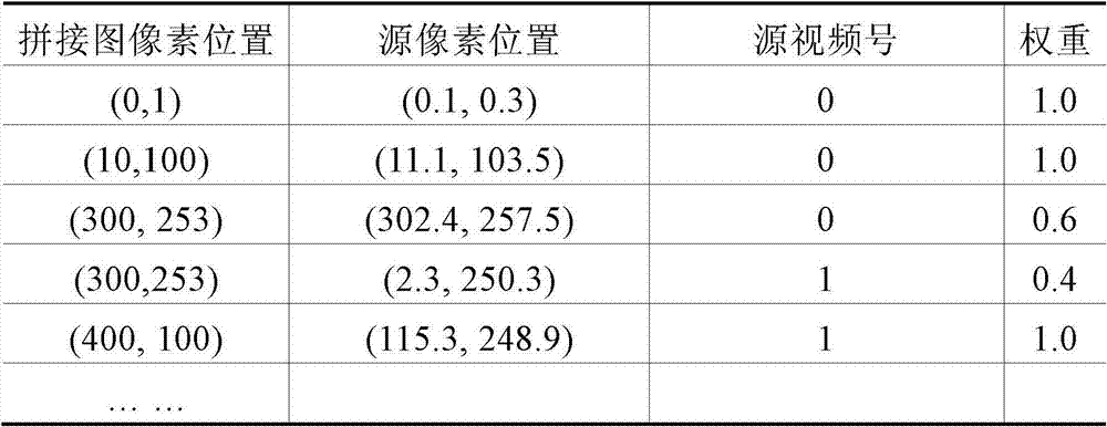
The first column of table 1 is the pixel location in the frame-stitched map. The second column is the corresponding pixel location in the source video frame. The third column is the source video number of the source pixel. The last column is the weight used for blending, where the pixel weight can be determined in a number of ways, for example, from the distance between a pixel and its corresponding image center as in equation 1. The third and fourth rows represent seam pixels having the same stitched image pixel location but different source pixel locations.
In equation 11, the scheme of the present invention requires calculation and the compensation term of off. In the compensation term, the product of adjacent projective transformations can be pre-computed and expressed as:
the compensation term can be calculated as follows:
wherein,dis that And its homogeneous coordinates are as follows:
the projection update requires 5 multiplications and 3 additions according to equation 14. It is worth noting that this compensation term is calculated only once and applies to all pixels within the source video frame. Therefore, the computation time of the compensation term for one frame is negligible. The final calculation is for 2 additions per pixel.
2.4 Pixel interpolation and blending
Once the reference projective transformation is determined, pixels from the source video frames can be mapped onto a frame-stitch map of the panoramic video. If the pixels in the frame mosaic have only one corresponding source video frame pixel, pixel interpolation can be used to obtain the pixel value. On the other hand, a pixel in a frame-spliced graph may have several corresponding source video frame pixels, which may be obtained by pixel blending. Pixel blending is a weighted pixel blending process. The weights are determined by the distance of the pixels in the reference plane from the center of its image. Such weights may also be pre-calculated in the pixel indexing step. For the pixel interpolation and blending process, reference [7] may be cited herein as a reference.
First embodiment
The first embodiment of the present invention will be described in further detail below with reference to fig. 1 and 5.
Fig. 1 shows a block diagram of a video stitching system according to a first embodiment of the invention. As shown in fig. 1, the video stitching system includes a camera array 100, a calibration apparatus 200, a stitching apparatus 300, and a pixel interpolator and mixer 400.
The camera array 100 has at least two cameras and provides source video from the cameras to the calibration apparatus 200, the stitching apparatus 300, and the pixel interpolator and mixer 400. In use, a user may select any camera in the camera array 100 and may also designate any of the selected cameras as the camera of interest (i.e., the image acquired by that camera is centered in the field of view). At least two cameras in the camera array 100 have overlapping fields of view.
The calibration apparatus 200 is configured to perform an initial calibration process (including epipolar calibration and projective transformation) based on source video transmitted from the camera array 100, and includes an epipolar calibrator 210, a camera position calibrator 230, a seam determiner 250, an index generator 260, and a multiplier 270. The epipolar calibrator 210 is used to calculate epipolar transformation parameters for each pair of adjacent frames and store the calculated parameters therein. The stored transformation parameters are sent to the seam determiner 250, the multiplier 270, and the offset value calculator 320 of the splicing apparatus 300. The camera position calibrator 230 is used to calculate adjacent projective transforms and reference projective transform parameters and store them therein. The stored transformation parameters are sent to the seam determiner 250, the index generator 260, and the multiplier 270. The seam determiner 250 is configured to calculate seam pixel locations and their weights based on the epipolar and adjacent projective transformation parameters of each adjacent frame pair from the epipolar calibrator 210 and the camera position calibrator 230. The seam area information is transmitted to the offset value calculator 320 of the splicing device 300 to perform offset value calculation, and is also transmitted to the index generator 260. The index generator 260 generates a pixel index table based on the reference projective transformation parameters from the camera position calibrator 230 and the seam region information and seam pixel weights from the seam determiner 250. The multiplier 270 multiplies the epipolar transform parameters and projective transform parameters from the epipolar calibrator 210 and the camera position calibrator 230, respectively, to generate and store a desired epipolar projective transform product to be used by the compensation calculator 330 of the stitching device 300.
The stitching device 300 is for rapidly updating a projective transformation from a source image (video) to a stitched image (video) by using estimated depth information (offset value), and includes an offset value calculator 320, a compensation calculator 330, and an index updater 340. The offset value calculator 320 is used for calculating an offset value of the current frame based on the epipolar transformation parameter from the epipolar calibrator 210 and the seam region information from the seam determiner 250. The calculated offset value is sent to the compensation calculator 330. The compensation calculator 330 is configured to calculate a compensation term for the reference projective transformation parameter already stored in the pixel index table generated by the index generator 260 based on the epipolar projective transformation product stored in the multiplier 270 and the offset value from the offset value calculator 320. Specifically, the compensation term is calculated according to equation 14. The calculated compensation term is sent to the index updater 340. The index updater 340 is configured to update the pixel correspondence under the new reference projective transformation parameter. The updated pixel index is sent to the pixel interpolator and mixer 400 to generate the mosaic.
The pixel interpolator and mixer 400 is configured to perform pixel interpolation and mixing processing to create a panoramic video from the source video transmitted from the camera array 100, based on the updated pixel index generated by the index updater 340 of the stitching device 300.
Next, an operation flow of the video stitching system (fig. 1) according to the first embodiment of the present invention will be described in detail with reference to fig. 5.
Fig. 5 shows a flow chart of a video splicing method according to a first embodiment of the invention. As shown in fig. 5, in step S400, the calibration apparatus 200 performs initialization (calibration step) to obtain the epipolar transformation parameter, the adjacent projective transformation parameter, the reference projective transformation parameter, the seam pixel position and its weight, and the pixel index table.
Thereafter, in step S510, the offset value calculator 320 of the stitching device 300 calculates an offset value of each corresponding point pair at the seam area determined by the seam determiner 250 within two spatially adjacent images in the plurality of source videos provided by the camera array 100, and in step S515, the offset value calculator 320 of the stitching device 300 averages the offset values of all corresponding point pairs at the seam area in the two spatially adjacent images to obtain an average offset value of the pair of spatially adjacent images. In step S520, the offset value calculator 320 determines whether there are any other pairs of spatially adjacent images in the image selected by the user. If so (YES in step S520), the offset value calculator 320 of the stitching device 300 repeats steps S510-S515 for the next pair of spatially adjacent images to calculate an average offset value for each pair of spatially adjacent images. If no other spatially neighboring image pair exists in the image selected by the user (no in step S520), the compensation calculator 330 of the stitching device 300 calculates a compensation term of the pixel index table (following equation 14) in step S525 by using the required epipolar projective transformation product from the multiplier 270 of the calibration device 200 and the average offset value of all spatially neighboring image pairs generated by the offset value calculator 320. Next, in step S530, the index updater 340 of the stitching device 300 updates the pixel index from the projection transformer 240 of the calibration device 200 with the compensation term calculated by the compensation calculator 340 of the stitching device 300 to obtain an updated pixel index table.
Thereafter, in step S600, the pixel interpolator and mixer 400 performs pixel interpolation and mixing on the source video from the camera array 100 by using the updated pixel index, thereby obtaining the panoramic video frame by frame in a real-time or near real-time manner.
Second embodiment
The second embodiment of the present invention will be described in further detail below with reference to fig. 6 and 7.
Fig. 6 shows a block diagram of a video stitching system according to a second embodiment of the invention. Compared to the first embodiment shown in fig. 1, the index generator 260 in the calibration apparatus 200 and the index updater 340 in the stitching apparatus 300 are replaced by a single unit called a correspondence calculator 340'; the multiplier 270 is omitted so that the outputs of the epipolar calibrator 210 and the camera position calibrator 230 are connected directly to the compensation calculator 330. Other components of the second embodiment are similar to those of the first embodiment, and thus detailed descriptions thereof are omitted for clarity and simplicity.
Since the multiplier 270 is omitted, the calibration apparatus 200 no longer outputs the required antipodal projective transformation product. Therefore, the compensation calculator 330 needs to calculate the required epipolar projective transformation product (following equation 13) from the directly input epipolar transformation parameters and projective transformation parameters.
The correspondence calculator 340' is used to generate pixel transformation correspondences between original pixels in the two original images and corresponding target pixels in the stitched image. The inputs to the correspondence calculator 340' include the reference projective transformation parameters from the camera position calibrator 230, the pixel weights from the seam determiner 250, the adjacent projective transformation parameters for each adjacent frame pair from the camera position calibrator 230, and the compensation terms for the pixel transformation from the compensation calculator 330. Specifically, the pixel transformation correspondence between the original pixel and the target pixel includes a positional correspondence and a weight (the weight is obtained directly from the seam determiner 250 of the calibration apparatus 200). The correspondence calculator 340' calculates the positional correspondence according to the above equation 11 so as to generate the pixel conversion correspondence in combination with the weight directly input.
Accordingly, the pixel interpolator and mixer 400 performs pixel interpolation and mixing processing to create a panoramic video from the source video transmitted from the camera array 100, based on the correspondence generated by the correspondence calculator 340' of the stitching device 300.
Next, an operation flow of the video stitching system (fig. 6) according to the second embodiment of the present invention will be described in detail with reference to fig. 7.
Fig. 7 shows a flow chart of a video splicing method according to a second embodiment of the invention. In contrast to fig. 5, steps 525 and 530 in fig. 5 are replaced by steps 525 'and 530', respectively. The other steps in fig. 7 are similar to those in fig. 5, and thus a detailed description thereof will be omitted for clarity and simplicity.
In step 525', the compensation calculator 330 of the stitching device 300 calculates a compensation term for the pixel transformation by using the epipolar transformation parameters from the epipolar transformer 220 of the calibration device 200, the projective transformation parameters from 240, and the average offset value for all spatially neighboring image pairs generated by the offset value calculator 320. Specifically, the compensation term is calculated according to equations 13 and 14. Next, in step S530 ', the correspondence calculator 340' of the mosaic device generates a pixel transformation relationship between original pixels in the two original images and corresponding target pixels in the mosaic image according to equation 11 by considering the compensation term calculated by the compensation calculator of the mosaic device 300.
Thereafter, in step S600, the pixel interpolator and mixer 400 performs pixel interpolation and facilitation on the source video from the camera array 100 based on the correspondence generated by the correspondence calculator 340' of the stitching device 300, thereby obtaining a panoramic video frame by frame in real time or near real time.
Comparing the first embodiment with the second embodiment, it can be seen that the first embodiment provides faster computation speed and requires more memory space. In the first embodiment, the epipolar projective transformation product is also generated and stored in advance in the initial calibration step; the correspondence between the original and target pixels is reflected in a pixel index table generated in advance in the initial calibration step. However, in the second embodiment, the epipolar calibration transform product and correspondence are repeatedly calculated for each frame pair. In addition, the inventors have found that the compensation terms for a pair of images are the same for all pixels therein, and thus in the first embodiment, the index update step will consume even less computational burden and time. However, in the second embodiment, such a compensation term is calculated once as in the first embodiment, but is reused in the correspondence calculation. From equation 11, it can be seen that such correspondence calculation will undoubtedly introduce more calculation burden than simply updating the index table. The second embodiment, although it brings more computational burden, will consume less memory space. The choice between the first and second embodiments is therefore a compromise between memory space and computational burden.
Although in the first and second embodiments the invention is implemented in a plurality of components. However, this configuration should not be construed as limiting the invention. In particular, the invention may be implemented with more or fewer components, or by dividing one of the above components into several components, or by combining some of the above components into a single component. Accordingly, the specific hardware configuration of the present invention is limited only by the appended claims and not by the above embodiments. Furthermore, as known to those skilled in the art, the present invention may also be implemented by software, hardware, firmware or a combination thereof.
Comparison results
Fig. 8(a) and 8(b) show an original image pair, where the two images are spatially adjacent. As a comparison, fig. 9 shows the result of the prior art stitching of the two images shown in fig. 8(a) and 8(b) (reference [2]), and fig. 10 shows the result of the inventive stitching of the two images shown in fig. 8(a) and 8 (b). It can clearly be seen that the stitching results of the present invention show good visual quality with less ghosting, especially in the seam area of the two original images.
The foregoing description merely presents preferred embodiments of the invention and is in no way intended to limit the invention. Accordingly, any modification, replacement, improvement or the like made within the spirit and principle of the present invention should fall within the scope of the present invention.
List of references
[1]Richard Szeliski.Image Alignment and Stitching:A Tutorial,Foundations and Trends in Computer Vision,Vol.2,No.1,pp.1-104,2006.
[2]US Patent Application Publication,No.US 2007/0211934A1,Patrick Pan,Tatsumi Mitsushita,Christine Lin,Benjamin Kuo,Optimized Video Stitching Method,September,2007.
[3]Tomoyuki Shimizu,Akio Yoneyama,Yasuhiro Takishima,AFast Video Stitching Method for Motion-Compensated Framesin Compressed Video Streams,Proceeding of InternationalConference on Consumer Electronics,pp.173-174,2006.
[4]Chris Harris and Mike Stephens.A Combined Corner and EdgeDetector.Proceedings of The Fourth Alvey Vision Conference,Manchester,pp 147-151.1988
[5]David G.Lowe.Distinctive Image Features fromScale-Invariant Keypoints.International Journal of ComputerVision,Vol.60,No.2,pp.91-110,2004.
[6]Hartley R,Zisserman A.Multiple View Geometrt in ComputerVision.Cambridge:University Press,2000.
[7]Matthew Alun Brown.Multi-Image Matching Using InvariantFeatures.Ph.D.Dissertation,the University of BritishColumbia,2005.
Claims (28)
1. A method of determining a depth compensation term in a video stitching application, comprising the steps of:
calculating an offset value for each corresponding point pair at a seam region within two spatially adjacent images in a plurality of source videos;
averaging the offset values of all corresponding point pairs at the seam area in the two spatially adjacent images to obtain an average offset value of the pair of spatially adjacent images; and
by using the epipolar transform parameters, the projective transform parameters, and the average offset values of all pairs of spatially neighboring images, a depth compensation term is calculated,
wherein the required antipodal projective transformation product is generated by multiplying the antipodal transformation parameter with the projective transformation parameter, and the depth compensation term is calculated by multiplying the required antipodal projective transformation product with the average offset value for all spatially adjacent image pairs.
2. The method of determining a depth compensation term in a video stitching application as recited in claim 1, further comprising, before the step of calculating the offset value, the steps of:
epipolar transformation parameters and projective transformation parameters are generated.
3. The method for determining a depth compensation term in a video stitching application as recited in claim 1, wherein the offset value for each corresponding point pair at the seam area is calculated by:
calculating the sum of the square brightness differences of the image corresponding to each offset value in the preset offset value range;
searching for a sum of least squared luminance differences among the calculated sums of luminance differences corresponding to all offset values in the predetermined offset value range; and
an offset value corresponding to the sum of the least squared luminance differences is determined as an offset value for the corresponding point pair.
4. An apparatus for determining a depth compensation term in a video stitching application, comprising:
means for calculating an offset value for each corresponding point pair at a seam region within two spatially adjacent images in a plurality of source videos;
means for averaging the offset values of all corresponding point pairs at the seam area within the two spatially adjacent images to obtain an average offset value for the pair of spatially adjacent images; and
means for calculating a depth compensation term by using the epipolar transform parameter, the projective transform parameter, and the average offset value for all pairs of spatially neighboring images,
wherein the means for calculating the depth compensation term generates a desired antipodal projective transformation product by multiplying the antipodal transformation parameter with the projective transformation parameter, and calculates the depth compensation term by multiplying the desired antipodal projective transformation product with the average offset value for all spatially adjacent image pairs.
5. A video stitching device, comprising:
an offset value calculator for calculating an offset value for each corresponding point pair at the seam area within two spatially adjacent images in the plurality of source videos, and averaging the offset values of all corresponding point pairs at the seam area within the two spatially adjacent images to obtain an average offset value for the pair of spatially adjacent images;
a compensation calculator for calculating a compensation item of the pixel index table by using the epipolar transformation parameter, the projective transformation parameter, and an average offset value of all the spatially neighboring image pairs generated by the offset value calculator; and
an index updater for updating the pixel corresponding relationship and the weight thereof in the pixel index table by the compensation item calculated by the compensation calculator to obtain an updated pixel index table,
wherein the epipolar transformation parameter, the projective transformation parameter, and the pixel index table are externally generated, and then a desired epipolar projective transformation product is externally generated by multiplying the epipolar transformation parameter by the projective transformation parameter, and
the compensation calculator calculates a compensation term for the pixel index table by multiplying the required epipolar projective transformation product with the average offset value for all spatially neighboring image pairs.
6. The video stitching device according to claim 5, wherein the update pixel index table is used externally to generate a panoramic video from the plurality of source videos.
7. The video stitching device of claim 5, wherein the offset value calculator calculates the offset value for each corresponding point pair at the seam area by:
calculating the sum of the square brightness differences of the image corresponding to each offset value in the preset offset value range;
searching for a sum of least squared luminance differences among the calculated sums of luminance differences corresponding to all offset values in the predetermined offset value range; and
an offset value corresponding to the sum of the least squared luminance differences is determined as an offset value for the corresponding point pair.
8. The video stitching device according to any one of claims 5 to 7, wherein the index table comprises pixel position correspondence and weights.
9. A video stitching system, comprising:
the video stitching device according to any one of claims 5 to 8; and
a pixel interpolator and mixer to generate a panoramic video from the plurality of source videos by using the updated pixel index table from the video stitching device.
10. The video stitching system of claim 9, further comprising:
and the calibration device is used for generating the epipolar transformation parameters, the projective transformation parameters, the pixel index table and the required epipolar projective transformation product.
11. The video stitching system of claim 10, wherein the calibration means comprises:
the antipodal calibrator is used for calculating and storing antipodal transformation parameters;
the camera position calibrator is used for calculating and storing projection transformation parameters;
a multiplier for multiplying the epipolar transform parameter by the projective transform parameter to generate a desired epipolar projective transform product;
a seam determiner for determining a seam region and weights of pixels at the seam region based on epipolar transformation parameters and projective transformation parameters from the epipolar calibrator and the camera position calibrator, respectively; and
and the index generator is used for generating a pixel index table based on the projective transformation parameters from the camera position calibrator and the seam area and the pixel weight from the seam determiner.
12. The video stitching system according to any one of claims 9 to 11, further comprising:
a camera array for generating the plurality of source videos, wherein at least two cameras in the camera array are spatially arranged with overlapping fields of view.
13. A video splicing method comprises the following steps:
calculating an offset value for each corresponding point pair at a seam region within two spatially adjacent images in a plurality of source videos;
averaging the offset values of all corresponding point pairs at the seam area in the two spatially adjacent images to obtain an average offset value of the pair of spatially adjacent images;
calculating a compensation term of the pixel index table by using the epipolar transformation parameter, the projective transformation parameter, and the average offset value of all pairs of spatially adjacent images; and
updating the pixel corresponding relation and the weight thereof in the pixel index table by the calculated compensation item to obtain an updated pixel index table,
wherein the compensation term of the pixel index table is calculated by externally generating a desired antipodal projective transformation product by multiplying the antipodal transformation parameter with the projective transformation parameter, and by multiplying the desired antipodal projective transformation product with the average offset value of all spatially neighboring image pairs.
14. The video stitching method as recited in claim 13, further comprising the steps of: using the updated pixel index table to generate a panoramic video from the plurality of source videos.
15. The video stitching method of claim 13, wherein the offset value for each corresponding point pair at the seam area is calculated by:
calculating the sum of the square brightness differences of the image corresponding to each offset value in the preset offset value range;
searching for a sum of least squared luminance differences among the calculated sums of luminance differences corresponding to all offset values in the predetermined offset value range; and
an offset value corresponding to the sum of the least squared luminance differences is determined as an offset value for the corresponding point pair.
16. The video splicing method according to any one of claims 13 to 15, wherein the index table comprises position correspondence and weights.
17. A video stitching device, comprising:
an offset value calculator for calculating an offset value for each corresponding point pair at the seam area within two spatially adjacent images in the plurality of source videos, and averaging the offset values of all corresponding point pairs at the seam area within the two spatially adjacent images to obtain an average offset value for the pair of spatially adjacent images;
a compensation calculator for calculating a compensation term for the pixel transformation by using the epipolar transformation parameter, the projective transformation parameter, and the average offset value of all spatially neighboring image pairs generated by the offset value calculator; and
a pixel correspondence calculator for calculating a positional correspondence between points within the two spatially neighboring images and their corresponding target points by using the epipolar transformation parameter, the projective transformation parameter, and the compensation term calculated by the compensation calculator to generate a pixel transformation correspondence including the calculated positional correspondence and an externally provided weight,
wherein the compensation calculator calculates the compensation term for the pixel by:
generating a required epipolar projective transformation product by multiplying the epipolar transformation parameter by the projective transformation parameter; and
the desired epipolar projective transformation product is multiplied by the average offset value of all spatially adjacent image pairs.
18. The video stitching device of claim 17, wherein the generated pixel transform correspondences are used externally to generate panoramic video from the plurality of source videos.
19. The video stitching device of claim 17, wherein the epipolar transform parameters and projective transform parameters are generated externally.
20. The video stitching device of claim 17, wherein the offset value calculator calculates the offset value for each corresponding point pair at the seam area by:
calculating the sum of the square brightness differences of the image corresponding to each offset value in the preset offset value range;
searching for a sum of least squared luminance differences among the calculated sums of luminance differences corresponding to all offset values in the predetermined offset value range; and
an offset value corresponding to the sum of the least squared luminance differences is determined as an offset value for the corresponding point pair.
21. A video stitching system, comprising:
the video stitching device according to any one of claims 17 to 20; and
a pixel interpolator and mixer to generate a panoramic video from the plurality of source videos by using the calculated pixel transformation correspondences from the video stitching device.
22. The video stitching system of claim 21, further comprising:
and the calibration device is used for generating the epipolar transformation parameters, the projective transformation parameters, the seam area and the weight of the pixel at the seam area.
23. The video stitching system of claim 22, wherein the calibration means comprises:
the antipodal calibrator is used for calculating and storing antipodal transformation parameters;
the camera position calibrator is used for calculating and storing projection transformation parameters; and
a seam determiner for determining a seam region and weights of pixels at the seam region based on the epipolar transformation parameters and projective transformation parameters from the epipolar calibrator and the camera position calibrator, respectively.
24. The video stitching system according to any one of claims 21 to 23, further comprising:
a camera array for generating the plurality of source videos, wherein at least two cameras in the camera array are spatially arranged with overlapping fields of view.
25. A video splicing method comprises the following steps:
calculating an offset value for each corresponding point pair at a seam region within two spatially adjacent images in a plurality of source videos;
averaging the offset values of all corresponding point pairs at the seam area in the two spatially adjacent images to obtain an average offset value of the pair of spatially adjacent images;
calculating a compensation term for the pixel transformation by using the epipolar transformation parameter, the projective transformation parameter, and the average offset value of all pairs of spatially adjacent images; and
calculating a positional correspondence between points within the two spatially neighboring images and their corresponding target points by using the epipolar transformation parameters, the projective transformation parameters, and the calculated compensation terms to generate a pixel transformation correspondence, the pixel transformation correspondence including the calculated positional correspondence and an externally provided weight,
wherein the compensation term for the pixel transformation is calculated by:
generating a required epipolar projective transformation product by multiplying the epipolar transformation parameter by the projective transformation parameter; and
the desired epipolar projective transformation product is multiplied by the average offset value of all spatially adjacent image pairs.
26. The video stitching method as recited in claim 25, further comprising the steps of: generating a panoramic video from the plurality of source videos using the generated pixel transformation correspondences.
27. The video stitching method according to claim 25, further comprising, before the step of calculating the offset value, the steps of:
and generating epipolar transformation parameters, projective transformation parameters, a seam region and the weight of the pixel at the seam region.
28. The video stitching method of claim 25, wherein the offset value for each corresponding point pair at the seam area is calculated by:
calculating the sum of the square brightness differences of the image corresponding to each offset value in the preset offset value range;
searching for a sum of least squared luminance differences among the calculated sums of luminance differences corresponding to all offset values in the predetermined offset value range; and
an offset value corresponding to the sum of the least squared luminance differences is determined as an offset value for the corresponding point pair.
Priority Applications (1)
| Application Number | Priority Date | Filing Date | Title |
|---|---|---|---|
| CN 200810099871 CN101593350B (en) | 2008-05-30 | 2008-05-30 | Depth adaptive video-splicing method, device and system thereof |
Applications Claiming Priority (1)
| Application Number | Priority Date | Filing Date | Title |
|---|---|---|---|
| CN 200810099871 CN101593350B (en) | 2008-05-30 | 2008-05-30 | Depth adaptive video-splicing method, device and system thereof |
Publications (2)
| Publication Number | Publication Date |
|---|---|
| CN101593350A CN101593350A (en) | 2009-12-02 |
| CN101593350B true CN101593350B (en) | 2013-01-09 |
Family
ID=41407992
Family Applications (1)
| Application Number | Title | Priority Date | Filing Date |
|---|---|---|---|
| CN 200810099871 Expired - Fee Related CN101593350B (en) | 2008-05-30 | 2008-05-30 | Depth adaptive video-splicing method, device and system thereof |
Country Status (1)
| Country | Link |
|---|---|
| CN (1) | CN101593350B (en) |
Cited By (1)
| Publication number | Priority date | Publication date | Assignee | Title |
|---|---|---|---|---|
| TWI572846B (en) * | 2015-09-18 | 2017-03-01 | 國立交通大學 | Panoramic image three-dimensional depth estimation system and panoramic image three-dimensional depth estimation method |
Families Citing this family (37)
| Publication number | Priority date | Publication date | Assignee | Title |
|---|---|---|---|---|
| US11792538B2 (en) | 2008-05-20 | 2023-10-17 | Adeia Imaging Llc | Capturing and processing of images including occlusions focused on an image sensor by a lens stack array |
| US8866920B2 (en) | 2008-05-20 | 2014-10-21 | Pelican Imaging Corporation | Capturing and processing of images using monolithic camera array with heterogeneous imagers |
| JP5126261B2 (en) * | 2010-03-18 | 2013-01-23 | 株式会社ニコン | camera |
| CN102006425B (en) * | 2010-12-13 | 2012-01-11 | 交通运输部公路科学研究所 | Method for splicing video in real time based on multiple cameras |
| US8878950B2 (en) | 2010-12-14 | 2014-11-04 | Pelican Imaging Corporation | Systems and methods for synthesizing high resolution images using super-resolution processes |
| US8542933B2 (en) | 2011-09-28 | 2013-09-24 | Pelican Imaging Corporation | Systems and methods for decoding light field image files |
| IL216515A (en) | 2011-11-22 | 2015-02-26 | Israel Aerospace Ind Ltd | System and method for processing multi-camera array images |
| US20140002674A1 (en) | 2012-06-30 | 2014-01-02 | Pelican Imaging Corporation | Systems and Methods for Manufacturing Camera Modules Using Active Alignment of Lens Stack Arrays and Sensors |
| WO2014031795A1 (en) | 2012-08-21 | 2014-02-27 | Pelican Imaging Corporation | Systems and methods for parallax detection and correction in images captured using array cameras |
| CN103973958B (en) * | 2013-01-30 | 2018-04-03 | 阿里巴巴集团控股有限公司 | Image processing method and equipment |
| US8866912B2 (en) | 2013-03-10 | 2014-10-21 | Pelican Imaging Corporation | System and methods for calibration of an array camera using a single captured image |
| CN103501415B (en) * | 2013-10-01 | 2017-01-04 | 中国人民解放军国防科学技术大学 | A kind of real-time joining method of video based on lap malformation |
| US9501864B2 (en) * | 2013-12-27 | 2016-11-22 | Intel Corporation | Adaptive depth offset compression |
| CN104240211B (en) * | 2014-08-06 | 2017-05-03 | 中国船舶重工集团公司第七0九研究所 | Image brightness and color balancing method and system for video stitching |
| WO2016054089A1 (en) | 2014-09-29 | 2016-04-07 | Pelican Imaging Corporation | Systems and methods for dynamic calibration of array cameras |
| CN106651755A (en) * | 2016-11-17 | 2017-05-10 | 宇龙计算机通信科技(深圳)有限公司 | Panoramic image processing method and device for terminal and terminal |
| CN108616733B (en) * | 2016-12-28 | 2020-01-10 | 深圳市掌网科技股份有限公司 | Panoramic video image splicing method and panoramic camera |
| CN107292822B (en) * | 2017-06-26 | 2020-08-28 | 北京奇艺世纪科技有限公司 | Image splicing method and device |
| CN108053803B (en) * | 2017-12-29 | 2020-01-10 | Oppo广东移动通信有限公司 | Display correction method, display correction device and display correction system of display module |
| CN108447022B (en) * | 2018-03-20 | 2019-10-18 | 北京天睿空间科技股份有限公司 | Moving target joining method based on single fixing camera image sequence |
| CN111385461B (en) * | 2018-12-28 | 2022-08-02 | 中兴通讯股份有限公司 | Panoramic shooting method and device, camera and mobile terminal |
| BR112022004811A2 (en) | 2019-09-17 | 2022-06-21 | Boston Polarimetrics Inc | Systems and methods for surface modeling using polarization indications |
| CN114746717A (en) | 2019-10-07 | 2022-07-12 | 波士顿偏振测定公司 | System and method for surface normal sensing using polarization |
| KR20230116068A (en) | 2019-11-30 | 2023-08-03 | 보스턴 폴라리메트릭스, 인크. | System and method for segmenting transparent objects using polarization signals |
| WO2021154386A1 (en) | 2020-01-29 | 2021-08-05 | Boston Polarimetrics, Inc. | Systems and methods for characterizing object pose detection and measurement systems |
| KR20220133973A (en) | 2020-01-30 | 2022-10-05 | 인트린식 이노베이션 엘엘씨 | Systems and methods for synthesizing data to train statistical models for different imaging modalities, including polarized images |
| US11953700B2 (en) | 2020-05-27 | 2024-04-09 | Intrinsic Innovation Llc | Multi-aperture polarization optical systems using beam splitters |
| US12020455B2 (en) | 2021-03-10 | 2024-06-25 | Intrinsic Innovation Llc | Systems and methods for high dynamic range image reconstruction |
| US12069227B2 (en) | 2021-03-10 | 2024-08-20 | Intrinsic Innovation Llc | Multi-modal and multi-spectral stereo camera arrays |
| US11954886B2 (en) | 2021-04-15 | 2024-04-09 | Intrinsic Innovation Llc | Systems and methods for six-degree of freedom pose estimation of deformable objects |
| US11290658B1 (en) | 2021-04-15 | 2022-03-29 | Boston Polarimetrics, Inc. | Systems and methods for camera exposure control |
| US12067746B2 (en) | 2021-05-07 | 2024-08-20 | Intrinsic Innovation Llc | Systems and methods for using computer vision to pick up small objects |
| US12175741B2 (en) | 2021-06-22 | 2024-12-24 | Intrinsic Innovation Llc | Systems and methods for a vision guided end effector |
| US12340538B2 (en) | 2021-06-25 | 2025-06-24 | Intrinsic Innovation Llc | Systems and methods for generating and using visual datasets for training computer vision models |
| US12172310B2 (en) | 2021-06-29 | 2024-12-24 | Intrinsic Innovation Llc | Systems and methods for picking objects using 3-D geometry and segmentation |
| US11689813B2 (en) | 2021-07-01 | 2023-06-27 | Intrinsic Innovation Llc | Systems and methods for high dynamic range imaging using crossed polarizers |
| US12293535B2 (en) | 2021-08-03 | 2025-05-06 | Intrinsic Innovation Llc | Systems and methods for training pose estimators in computer vision |
Citations (3)
| Publication number | Priority date | Publication date | Assignee | Title |
|---|---|---|---|---|
| US20070031062A1 (en) * | 2005-08-04 | 2007-02-08 | Microsoft Corporation | Video registration and image sequence stitching |
| US20070211934A1 (en) * | 2006-03-10 | 2007-09-13 | Sony Taiwan Limited | Optimized video stitching method |
| CN101112315A (en) * | 2007-08-24 | 2008-01-30 | 珠海友通科技有限公司 | X-ray human body clairvoyance image automatic anastomosing and splicing method |
-
2008
- 2008-05-30 CN CN 200810099871 patent/CN101593350B/en not_active Expired - Fee Related
Patent Citations (3)
| Publication number | Priority date | Publication date | Assignee | Title |
|---|---|---|---|---|
| US20070031062A1 (en) * | 2005-08-04 | 2007-02-08 | Microsoft Corporation | Video registration and image sequence stitching |
| US20070211934A1 (en) * | 2006-03-10 | 2007-09-13 | Sony Taiwan Limited | Optimized video stitching method |
| CN101112315A (en) * | 2007-08-24 | 2008-01-30 | 珠海友通科技有限公司 | X-ray human body clairvoyance image automatic anastomosing and splicing method |
Non-Patent Citations (2)
| Title |
|---|
| Tomoyuki SHIMIZU, Akio YONEYAMA and Yasuhiro TAKISHIMA.A Fast Video Stitching Method for Motion-Compensated Frames in Compressed Video Streams.《International conference on consumer electronics, 2006》.2006,173-174. * |
| TomoyukiSHIMIZU Akio YONEYAMA and Yasuhiro TAKISHIMA.A Fast Video Stitching Method for Motion-Compensated Frames in Compressed Video Streams.《International conference on consumer electronics |
Cited By (1)
| Publication number | Priority date | Publication date | Assignee | Title |
|---|---|---|---|---|
| TWI572846B (en) * | 2015-09-18 | 2017-03-01 | 國立交通大學 | Panoramic image three-dimensional depth estimation system and panoramic image three-dimensional depth estimation method |
Also Published As
| Publication number | Publication date |
|---|---|
| CN101593350A (en) | 2009-12-02 |
Similar Documents
| Publication | Publication Date | Title |
|---|---|---|
| CN101593350B (en) | Depth adaptive video-splicing method, device and system thereof | |
| US8194184B2 (en) | Method and apparatus for increasing the frame rate of a video signal | |
| CN101923709B (en) | Image splicing method and equipment | |
| TWI622021B (en) | Panoramic image generation method and device with joint function | |
| Sinha et al. | Pan–tilt–zoom camera calibration and high-resolution mosaic generation | |
| JP7093015B2 (en) | Panorama video compositing device, panoramic video compositing method, and panoramic video compositing program | |
| EP1583357A2 (en) | Imaging system, image data stream creation apparatus, image generation apparatus, image data stream generation apparatus, and image data stream generation system | |
| CN106856000B (en) | Seamless splicing processing method and system for vehicle-mounted panoramic image | |
| EP0983574A1 (en) | Combining digital images | |
| Kumar et al. | Stereo rectification of uncalibrated and heterogeneous images | |
| CN103105858A (en) | Method capable of amplifying and tracking goal in master-slave mode between fixed camera and pan tilt zoom camera | |
| WO2005024723A1 (en) | Image combining system, image combining method, and program | |
| EP3446283A1 (en) | Image stitching method and device | |
| JP4887376B2 (en) | A method for obtaining a dense parallax field in stereo vision | |
| Babbar et al. | Homography theories used for image mapping: a review | |
| CN118301488A (en) | Method, device and non-transitory computer readable medium for field of view extension based on super-resolution | |
| EP2297702B1 (en) | Complex wavelet tracker | |
| CN104574276A (en) | Method and device for aligning images on basis of optical flow | |
| JP2005141655A (en) | Three-dimensional modeling apparatus and three-dimensional modeling method | |
| JP2009282762A (en) | Corresponding point retrieval device | |
| Liang et al. | Unified Vertex Motion Estimation for integrated video stabilization and stitching in tractor–trailer wheeled robots | |
| Pandey et al. | A novel technique for mosaicing of medical images | |
| Dornaika et al. | Mosaicking images with parallax | |
| JPH0918685A (en) | Image composition method | |
| JP4102386B2 (en) | 3D information restoration device |
Legal Events
| Date | Code | Title | Description |
|---|---|---|---|
| C06 | Publication | ||
| PB01 | Publication | ||
| C10 | Entry into substantive examination | ||
| SE01 | Entry into force of request for substantive examination | ||
| C14 | Grant of patent or utility model | ||
| GR01 | Patent grant | ||
| CF01 | Termination of patent right due to non-payment of annual fee |
Granted publication date: 20130109 Termination date: 20180530 |
|
| CF01 | Termination of patent right due to non-payment of annual fee |