CN101569541B - Three-dimensional ultrasonic imaging system - Google Patents
Three-dimensional ultrasonic imaging system Download PDFInfo
- Publication number
- CN101569541B CN101569541B CN2008100943819A CN200810094381A CN101569541B CN 101569541 B CN101569541 B CN 101569541B CN 2008100943819 A CN2008100943819 A CN 2008100943819A CN 200810094381 A CN200810094381 A CN 200810094381A CN 101569541 B CN101569541 B CN 101569541B
- Authority
- CN
- China
- Prior art keywords
- imaging system
- ultrasonic imaging
- dimensional ultrasonic
- photographic head
- positioning mark
- Prior art date
- Legal status (The legal status is an assumption and is not a legal conclusion. Google has not performed a legal analysis and makes no representation as to the accuracy of the status listed.)
- Active
Links
Images


Classifications
-
- A—HUMAN NECESSITIES
- A61—MEDICAL OR VETERINARY SCIENCE; HYGIENE
- A61B—DIAGNOSIS; SURGERY; IDENTIFICATION
- A61B8/00—Diagnosis using ultrasonic, sonic or infrasonic waves
-
- A—HUMAN NECESSITIES
- A61—MEDICAL OR VETERINARY SCIENCE; HYGIENE
- A61B—DIAGNOSIS; SURGERY; IDENTIFICATION
- A61B8/00—Diagnosis using ultrasonic, sonic or infrasonic waves
- A61B8/42—Details of probe positioning or probe attachment to the patient
- A61B8/4245—Details of probe positioning or probe attachment to the patient involving determining the position of the probe, e.g. with respect to an external reference frame or to the patient
-
- A—HUMAN NECESSITIES
- A61—MEDICAL OR VETERINARY SCIENCE; HYGIENE
- A61B—DIAGNOSIS; SURGERY; IDENTIFICATION
- A61B8/00—Diagnosis using ultrasonic, sonic or infrasonic waves
- A61B8/48—Diagnostic techniques
- A61B8/483—Diagnostic techniques involving the acquisition of a 3D volume of data
Landscapes
- Life Sciences & Earth Sciences (AREA)
- Health & Medical Sciences (AREA)
- Biomedical Technology (AREA)
- Biophysics (AREA)
- Nuclear Medicine, Radiotherapy & Molecular Imaging (AREA)
- Pathology (AREA)
- Radiology & Medical Imaging (AREA)
- Engineering & Computer Science (AREA)
- Physics & Mathematics (AREA)
- Heart & Thoracic Surgery (AREA)
- Medical Informatics (AREA)
- Molecular Biology (AREA)
- Surgery (AREA)
- Animal Behavior & Ethology (AREA)
- General Health & Medical Sciences (AREA)
- Public Health (AREA)
- Veterinary Medicine (AREA)
- Ultra Sonic Daignosis Equipment (AREA)
Abstract
本发明提供一种三维超声波成像系统,包括超声波探头、摄像头、定位模块、超声波扫描仪以及计算模块,其中所述摄像头附着于所述超声波探头上,所述定位模块放置在所述摄像头的取景范围内,超声波扫描仪提供身体各部相应的超声波图像,同时摄像头提供实时视频,计算模块同时收集扫描图像和视频并执行相应计算生成三维图像。本发明优点在于其成本低廉,并能够提高三维超声波成像空间跟踪的准确性。
The present invention provides a three-dimensional ultrasonic imaging system, comprising an ultrasonic probe, a camera, a positioning module, an ultrasonic scanner and a computing module, wherein the camera is attached to the ultrasonic probe, the positioning module is placed within the viewing range of the camera, the ultrasonic scanner provides corresponding ultrasonic images of various parts of the body, the camera provides real-time video, and the computing module collects the scanned image and video at the same time and performs corresponding calculations to generate a three-dimensional image. The present invention has the advantages of low cost and the ability to improve the accuracy of spatial tracking of three-dimensional ultrasonic imaging.
Description
技术领域technical field
本发明涉及三维超声波成像系统。The invention relates to a three-dimensional ultrasonic imaging system.
背景技术Background technique
最近,对三维诊断实践重视使三维超声波设备得到快速发展。较之CT和MRI成像,三维超声波是获取立体成像的低成本解决方案。此外,其操作无须集中培训和辐射保护。而且其硬件可以拆卸且有可能具有便携性。三维超声波成像已广泛用于异常胎儿、淋巴结和心脏等疾病的检查或诊断。Recently, the emphasis on 3D diagnostic practice has resulted in the rapid development of 3D ultrasound equipment. Compared to CT and MRI imaging, 3D ultrasound is a low-cost solution for obtaining stereo imaging. In addition, its operation does not require intensive training and radiation protection. And its hardware is detachable and potentially portable. Three-dimensional ultrasound imaging has been widely used in the examination or diagnosis of diseases such as abnormal fetus, lymph nodes and heart.
最近有针对三维超声波成像开发了很多不同技术。鉴于获取方法,其可分为四类:二维转换器阵列、机械扫描仪以及具有和不具有位置信息的徒手扫描方法。A number of different techniques have recently been developed for 3D ultrasound imaging. In view of the acquisition methods, they can be divided into four categories: 2D transducer arrays, mechanical scanners, and freehand scanning methods with and without position information.
二维转换器阵列的系统可实时提供大量重要三维图像,但是较为昂贵且不易购买。Systems of arrays of 2D transducers can provide a large number of important 3D images in real time, but are expensive and not readily available.
机械扫描方法中,超声波转换器被转动或调动从而通过从位于扫描头的步进电机获取位置数据。根据机械移动的类型,可采用线性移动将得到的B超声波扫描排列成一系列平行的片段,采用倾斜移动将得到的B超声波扫描排列成楔形,采用旋转移动将得到的B超声波扫描排列成锥形或圆柱形,因此为位置测量提供高准确性,但是机械扫描方法的移动范围受扫描设备限制。In the mechanical scanning method, the ultrasonic transducer is rotated or maneuvered to obtain position data from a stepper motor located at the scanning head. Depending on the type of mechanical movement, the resulting B-scans can be arranged in a series of parallel segments using linear movement, in a wedge shape using oblique movement, in a cone or in a rotary movement Cylindrical, thus providing high accuracy for position measurement, but the range of movement of mechanical scanning methods is limited by the scanning device.
相对于机械扫描方法,临床医生通过徒手扫描方法在体表操作超声波探头所受限制更小。探头的位置和方向可使用方位感应设备记录下来,并用于重建三维数据集。现有许多不同的方位传感器可供使用,包括电磁感性设备、脉冲超声定位、铰接臂和光学传感器。上述设备都较为昂贵、庞大或不准确。也有很多设备不使用任何方位感应设备但通过获取自图像的信息估测B超声波扫描之间的相对位置和方向。但是,此类设备要求探头可在一个方向上稳定移动但不能在B超声波扫描时进行大规模转动和变换。此外,由于在数据获取期间移动测量产生的错误,此类设备不能提供准确的距离或体积测量。Compared with mechanical scanning methods, clinicians are less restricted in manipulating ultrasound probes on the body surface by freehand scanning methods. The position and orientation of the probe can be recorded using an orientation-sensing device and used to reconstruct a 3D dataset. Many different orientation sensors are available, including electromagnetic inductive devices, pulsed ultrasound positioning, articulated arms, and optical sensors. All of the above devices are expensive, bulky or inaccurate. There are also many devices that do not use any orientation sensing devices but estimate the relative position and orientation between B-ultrasound scans by information obtained from the images. However, this type of equipment requires that the probe can move steadily in one direction but cannot perform large-scale rotation and transformation during B-ultrasound scanning. In addition, such devices cannot provide accurate distance or volume measurements due to errors introduced by movement measurements during data acquisition.
发明内容Contents of the invention
本发明目的在于一种三维超声波成像系统,其具有测量准确性,简单的步骤以及低廉的成本。The present invention aims at a three-dimensional ultrasound imaging system with measurement accuracy, simple steps and low cost.
本发明提供一种三维超声波成像系统,包括超声波探头、至少一个第一摄像头、定位模块、超声波扫描仪以及计算模块,其中所述摄像头附着于所述超声波探头上,所述定位模块放置在所述摄像头的取景范围内,超声波扫描仪提供身体各部位相应的超声波图像,同时摄像头提供实时视频,计算模块同时收集扫描图像和视频并执行相应计算生成三维图像;所述定位模块包括一组定位标识,所述定位标识包括两条相互垂直平分的线段以及四个位于线端的标识块,所述四个标识块具有已知面积和中心,所述计算模块根据当前定位标识和初始定位标识之间的相对关系计算生成三维图像。The present invention provides a three-dimensional ultrasonic imaging system, including an ultrasonic probe, at least one first camera, a positioning module, an ultrasonic scanner, and a computing module, wherein the camera is attached to the ultrasonic probe, and the positioning module is placed on the Within the viewing range of the camera, the ultrasonic scanner provides corresponding ultrasonic images of various parts of the body, while the camera provides real-time video, and the calculation module simultaneously collects the scanned image and video and performs corresponding calculations to generate a three-dimensional image; the positioning module includes a set of positioning marks, The positioning mark includes two mutually perpendicular and bisected line segments and four marking blocks at the end of the line, the four marking blocks have known areas and centers, and the calculation module is based on the relative relationship between the current positioning mark and the initial positioning mark. Relational calculations generate 3D images.
如本发明的优选实施例所述的三维超声波成像系统,所述摄像头为黑白摄像头、彩色摄像头或红外摄像头。According to the three-dimensional ultrasonic imaging system described in the preferred embodiment of the present invention, the camera is a black and white camera, a color camera or an infrared camera.
如本发明的优选实施例所述的三维超声波成像系统,在所述摄像头或所述定位模块中附加照明单元。According to the three-dimensional ultrasonic imaging system described in the preferred embodiment of the present invention, an illumination unit is added to the camera or the positioning module.
如本发明的优选实施例所述的三维超声波成像系统,所述摄像头与超声波探头成一体化。According to the three-dimensional ultrasonic imaging system described in the preferred embodiment of the present invention, the camera is integrated with the ultrasonic probe.
如本发明的优选实施例所述的三维超声波成像系统,所述超声波探头上有一按键用来设定实时视频的初始帧。According to the three-dimensional ultrasonic imaging system described in the preferred embodiment of the present invention, there is a button on the ultrasonic probe for setting the initial frame of the real-time video.
如本发明的优选实施例所述的三维超声波成像系统,还包括第二摄像头,用于观测所述身体各部位以确定相应身体各部位的移动并修正所获得的所述超声波探头的移动。The three-dimensional ultrasound imaging system according to the preferred embodiment of the present invention further includes a second camera for observing the body parts to determine the movement of the corresponding body parts and correcting the obtained movement of the ultrasound probe.
如本发明的优选实施例所述的三维超声波成像系统,所述定位标识中的所述线段和标识块都有其特定的编码。According to the three-dimensional ultrasonic imaging system described in the preferred embodiment of the present invention, the line segment and the identification block in the positioning identification have their specific codes.
如本发明的优选实施例所述的三维超声波成像系统,所述计算模块根据在一平面内当前线段交点和初始线段交点之间的距离确定在所述平面内扫描的位移。According to the three-dimensional ultrasonic imaging system described in the preferred embodiment of the present invention, the calculation module determines the displacement of scanning in a plane according to the distance between the intersection point of the current line segment and the intersection point of the initial line segment in the plane.
如本发明的优选实施例所述的三维超声波成像系统,所述计算模块根据在一平面内当前线段和初始线段之间的角度确定在所述平面内扫描的转动角度。According to the three-dimensional ultrasonic imaging system described in the preferred embodiment of the present invention, the calculation module determines the rotation angle of scanning in a plane according to the angle between the current line segment and the initial line segment in the plane.
如本发明的优选实施例所述的三维超声波成像系统,所述计算模块根据在一方向上垂直于所述方向的当前线段和初始线段的长度比率确定在所述方向上扫描的位移。According to the three-dimensional ultrasonic imaging system described in the preferred embodiment of the present invention, the calculation module determines the displacement of scanning in a direction according to the length ratio of the current line segment perpendicular to the direction and the initial line segment.
如本发明的优选实施例所述的三维超声波成像系统,所述计算模块根据在以一方向为轴转动时,所述轴两侧的标识块的当前面积的比率确定以所述方向为轴的转动的角度。According to the three-dimensional ultrasonic imaging system described in the preferred embodiment of the present invention, the calculation module determines the current area ratio of the identification blocks on both sides of the axis when the axis is rotated in one direction. The angle of rotation.
如本发明的优选实施例所述的三维超声波成像系统,所述计算模块根据在以一方向为轴转动时,线段当前交点在与所述轴垂直的线段上的位置确定以所述方向为轴的转动的角度。According to the three-dimensional ultrasonic imaging system described in the preferred embodiment of the present invention, the calculation module determines the axis with the direction as the axis according to the position of the current intersection point of the line segment on the line segment perpendicular to the axis when the axis is rotated in a direction angle of rotation.
如本发明的优选实施例所述的三维超声波成像系统,所述定位模块包括在沿一个方向连续排列的多组定位标识,针对定位标识的跟踪将随摄像头的移动从采用当前组定位标识转移到下一组定位标识。According to the three-dimensional ultrasonic imaging system described in the preferred embodiment of the present invention, the positioning module includes multiple groups of positioning marks arranged continuously in one direction, and the tracking for the positioning marks will be transferred from using the current group of positioning marks to The next set of positioning identifiers.
如本发明的优选实施例所述的三维超声波成像系统,所述定位模块包括沿两相互垂直方向矩阵排列的多组定位标识,针对定位标识的跟踪将随摄像头的移动从采用当前组定位标识转移到下一组定位标识。According to the three-dimensional ultrasonic imaging system described in the preferred embodiment of the present invention, the positioning module includes multiple sets of positioning marks arranged in a matrix along two mutually perpendicular directions, and the tracking for the positioning marks will be transferred from using the current set of positioning marks with the movement of the camera. to the next set of anchor ids.
一种三维超声波成像方法,包括以下步骤:1)利用位于超声波探头上的摄像头获取定位模块的实时视频图像;2)同时利用超声波扫描仪通过所述超声波探头获得身体各部位相应的超声波图像;3)利用计算模块通过比较连续的实时视频图像中的所述定位模块的各单元的位置、角度及面积从而得到所述超声波探头的移动及旋转量;4)通过重复上述操作以获得一系列超声波图像以及获得相应超声图像时所述超声波探头和方向;5)计算模块利用获得的数据执行相应计算生成三维图像。A three-dimensional ultrasonic imaging method, comprising the following steps: 1) utilizing a camera positioned on an ultrasonic probe to acquire a real-time video image of a positioning module; 2) simultaneously utilizing an ultrasonic scanner to obtain corresponding ultrasonic images of various parts of the body through the ultrasonic probe; 3 ) using the calculation module to obtain the movement and rotation of the ultrasonic probe by comparing the position, angle and area of each unit of the positioning module in continuous real-time video images; 4) obtaining a series of ultrasonic images by repeating the above operations and the ultrasonic probe and direction when obtaining the corresponding ultrasonic image; 5) the calculation module uses the obtained data to perform corresponding calculations to generate a three-dimensional image.
本发明优点在于其成本低廉,并能够提高三维超声波成像空间跟踪的准确性。The invention has the advantages of low cost and can improve the accuracy of three-dimensional ultrasonic imaging space tracking.
附图说明Description of drawings
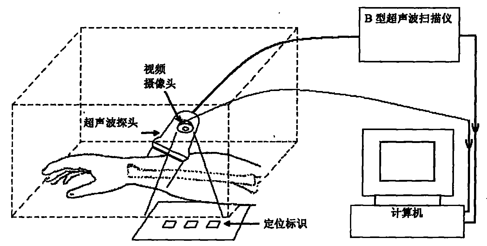
图1为根据本发明的三维超声波成像系统的示意图;1 is a schematic diagram of a three-dimensional ultrasonic imaging system according to the present invention;
图2显示一组典型的初始定位标识;Figure 2 shows a typical set of initial location markers;
图3显示摄像头在x-y平面进行变换后的定位标识以及初始标识;Fig. 3 shows the positioning mark and the initial mark of the camera after transformation on the x-y plane;
图4显示摄像头在z方向进行变换后的定位标识以及初始标识;Figure 4 shows the positioning mark and initial mark of the camera after transformation in the z direction;
图5显示摄像头在x-y平面进行转动后的定位标识以及初始标识;Figure 5 shows the positioning mark and initial mark of the camera after it is rotated on the x-y plane;
图6显示摄像头在x-z平面进行转动后的定位标识以及初始标识;Figure 6 shows the positioning mark and initial mark of the camera after it is rotated on the x-z plane;
图7显示摄像头在y-z平面进行转动后的定位标识以及初始标识;Figure 7 shows the positioning mark and the initial mark of the camera after it is rotated on the y-z plane;
图8显示摄像头的复杂的移动后的定位标识以及初始标识;Fig. 8 shows the positioning mark and the initial mark after the complex movement of the camera;
图9显示在一个方向连续排列的多组定位标识;以及Figure 9 shows multiple sets of positioning marks arranged continuously in one direction; and
图10显示在两个相互垂直方向连续排列的多组定位标识。Fig. 10 shows multiple sets of positioning marks arranged continuously in two mutually perpendicular directions.
具体实施方式Detailed ways
本发明为一个三维超声波成像系统,所述系统的原理在于采用视频摄像头附着于超声波探头上作为方位感应装置以及定位标识图表来构建三维超声波成像。The present invention is a three-dimensional ultrasonic imaging system. The principle of the system is to use a video camera attached to an ultrasonic probe as an orientation sensing device and a positioning identification chart to construct a three-dimensional ultrasonic imaging.
如图1所示,根据本发明的三维超声波成像系统,所述系统包括超声波探头、视频生成模块、超声波扫描仪以及计算机,其中超声波扫描仪可提供身体各部相应的超声波图像,视频生成模块包括摄像头和定位模块,所述摄像头附着于所述超声波探头上,所述定位模块放置在所述摄像头的取景范围内,因此视频生成模块可提供实时视频流,计算模块同时收集扫描图像和视频流并执行相应计算生成三维图像。所述摄像头有一个或一个以上,所述定位模块可以主动发光,所述摄像头与超声波探头集成一体,所述超声波探头用于二维或三维成像。As shown in Figure 1, according to the three-dimensional ultrasonic imaging system of the present invention, the system includes an ultrasonic probe, a video generation module, an ultrasonic scanner and a computer, wherein the ultrasonic scanner can provide corresponding ultrasonic images of each part of the body, and the video generation module includes a camera and a positioning module, the camera is attached to the ultrasonic probe, the positioning module is placed within the viewfinder range of the camera, so the video generation module can provide real-time video streams, and the calculation module simultaneously collects scanned images and video streams and executes The corresponding calculations generate a three-dimensional image. There is one or more than one camera, the positioning module can actively emit light, the camera is integrated with an ultrasonic probe, and the ultrasonic probe is used for two-dimensional or three-dimensional imaging.
当在超声波探头沿身体各部移动时,超声波扫描仪可提供身体各部相应的超声波图像。同时摄像头可基于定位标识图表提供实时视频流。计算机可同时收集B超声波扫描图像和视频流并执行相应计算。根据视频图像的内容变化,可计算视频摄像头的位置和方向。由于摄像头固定于超声波探头,所以也可获得所述探头的位置和方向。因此,可相应得到每个B超声波图像的位置和方向同时可生成三维图像,同时所述身体各部位受到第二摄像头的观测以确定相应身体各部位的移动并用得到的结果对所获得的所述超声波探头的移动进行修正。As the ultrasound probe is moved along various parts of the body, the ultrasound scanner provides corresponding ultrasound images of each part of the body. At the same time, the camera can provide real-time video stream based on the positioning identification chart. The computer simultaneously collects B-ultrasound scan images and video streams and performs calculations accordingly. According to the content change of the video image, the position and direction of the video camera can be calculated. Since the camera is fixed to the ultrasound probe, the position and orientation of the probe can also be obtained. Therefore, the position and direction of each B ultrasonic image can be correspondingly obtained and a three-dimensional image can be generated, and at the same time, each part of the body is observed by the second camera to determine the movement of each part of the corresponding body, and the obtained results are used to compare the obtained The movement of the ultrasonic probe is corrected.
图2显示了一组典型的定位标识。A、B、C、D为四个定位标识块,其分别具有已知面积和中心。线段a为以定位标识块A和定位标识块C的中心点为端点的已知线段。线段b为以定位标识块B和定位标识块D的中心点为端点的已知线段。O为线段a和b的交点。Figure 2 shows a typical set of location markers. A, B, C, and D are four positioning markers, which respectively have known areas and centers. The line segment a is a known line segment whose endpoint is the center point of the positioning marker block A and the positioning marker block C. The line segment b is a known line segment whose endpoint is the center point of the positioning marker block B and the positioning marker block D. O is the intersection of line segments a and b.
存在多种通过摄像头获取的视频计算所述摄像头的位置和方向的方法,如图3-7所示,定位标识的图像可通过视频摄像头实时获取。首先,所述超声波探头上有一按键用来设定实时视频的初始帧,通过按下所述按键,计算机记录在第一帧图像中可识别标识块A、B、C、D及其位置,从而计算各个标识块的初始面积及其间距离,所述定位模块中的每一定位标识块和线段都有其特定的编码从而可以图像识别得知在当前的图像中有哪些单元存在及它们的具体位置。在接下来的帧中,摄像头在多个方向发生变换或在多个平面发生转动。图3-7显示不同的情况并描述了如何计算变换和转动。There are many methods for calculating the position and direction of the camera through the video captured by the camera. As shown in FIG. 3-7, the image of the positioning mark can be obtained in real time through the video camera. First of all, there is a button on the ultrasonic probe to set the initial frame of the real-time video, by pressing the button, the computer records the identifiable blocks A, B, C, D and their positions in the first frame image, thereby Calculate the initial area and the distance between each identification block, each positioning identification block and line segment in the positioning module has its specific code so that image recognition can know which units exist and their specific positions in the current image . In subsequent frames, the camera is transformed in multiple directions or rotated in multiple planes. Figures 3-7 show the different situations and describe how transformations and rotations are calculated.
图3显示摄像头在x-y平面进行变换后的定位标识以及初始标识。在x和y方向的准确位移可从初始线段交点“O”和当前线段交点“O1”的位置计算得出。Fig. 3 shows the positioning mark and the initial mark of the camera after transformation on the x-y plane. The exact displacement in the x and y directions can be calculated from the position of the intersection point "O" of the initial segment and the intersection point "O1" of the current segment.
图4显示摄像头在z方向进行变换后的定位标识以及初始标识。在z方向上的位移可从块之间的距离以及块的维度的变化计算得出。线段a2/a和线段b2/b的比率可用于通过标度计算位移,其中,a2、b2为当前线段,a、b为初始线段其可在测量之前确定。Fig. 4 shows the positioning mark and the initial mark of the camera after transformation in the z direction. The displacement in the z direction can be calculated from the distance between the blocks and the change in the dimension of the blocks. The ratio of line segment a2/a and line segment b2/b can be used to calculate the displacement by scale, where a2, b2 is the current line segment and a, b is the initial line segment which can be determined before the measurement.
图5显示摄像头在x-y平面进行转动后的定位标识以及初始标识。所述转动的确切角度可基于线a或b的方向变化进行计算,也就是,从初始线段a到当前线段a3的角度或从初始线段b到当前线段b3的角度。Fig. 5 shows the positioning mark and the initial mark after the camera rotates on the x-y plane. The exact angle of said rotation may be calculated based on the change in direction of line a or b, ie the angle from initial line segment a to current line segment a3 or from initial line segment b to current line segment b3.
图6显示摄像头在x-z平面进行转动后的定位标识以及初始标识。所述转动量可通过当前标识块B4和当前标识块D4的面积比率或当前交点O4在当前线段a4上的重新定位计算得出。在此情况下,在y-z方向不存在转动。因此,当前标识块A4和C4的面积是相同的。Figure 6 shows the positioning mark and the initial mark of the camera after it is rotated on the x-z plane. The amount of rotation can be calculated through the area ratio of the current marker block B4 and the current marker block D4 or the repositioning of the current intersection point O4 on the current line segment a4. In this case there is no rotation in the y-z direction. Therefore, the areas of the current identification blocks A4 and C4 are the same.
图7显示摄像头在y-z平面进行转动后的定位标识以及初始标识。所述转动量可通过当前标识块A5和当前标识块C5的面积比率或当前点O5在当前线段b5上的重新定位计算得出。在此情况下,在x-z方向不存在转动。因此,当前标识块B5和D5的面积是相同的。Fig. 7 shows the positioning mark and the initial mark after the camera rotates on the y-z plane. The amount of rotation can be calculated through the area ratio of the current marker block A5 and the current marker block C5 or the repositioning of the current point O5 on the current line segment b5. In this case there is no rotation in the x-z direction. Therefore, the areas of the current identification blocks B5 and D5 are the same.
图8显示摄像头的复杂的移动后的定位标识以及初始标识。所述移动综合了图3-7所有的变换和转动。其在x、y和z方向上都有变换,在x-y、x-z和y-z平面上。基于图3-7所述的方法可计算变换和转动。Fig. 8 shows the location identification and the initial identification of the complex movement of the camera. The movement combines all the transformations and rotations of Figures 3-7. It has transformations in the x, y and z directions, on the x-y, x-z and y-z planes. Transformations and rotations can be calculated based on the methods described in Figures 3-7.
在上述举例中,基本的要求是定位标识必须在摄像头的取景范围内。否则,变换和转动不可能准确计算。因此,图3-8中详述的方法对于相对小的移动也适用。为了适用于大的移动量,可采用多组定位标识。In the above example, the basic requirement is that the positioning mark must be within the viewing range of the camera. Otherwise, transformations and rotations cannot be calculated accurately. Therefore, the method detailed in Figures 3-8 also works for relatively small movements. In order to be suitable for a large amount of movement, multiple sets of positioning marks can be used.
图9显示在一个方向延伸的多组定位标识,以及在此方向上更大的移动范围。当一组定位标识开始从摄像头的取景范围内消失,则另一组定位标识出现在取景范围内。当此现象发生,定位标识的跟踪将从采用第一组定位标识转移到第二组定位标识。所述过程可持续进行,从而实现在一个方向上延伸一个较大取景范围。Figure 9 shows multiple sets of positioning markers extending in one direction, and a greater range of movement in that direction. When one group of positioning marks starts to disappear from the viewing range of the camera, another group of positioning marks appears in the viewing range. When this phenomenon occurs, the tracking of the location markers will be shifted from using the first set of location markers to the second set of location markers. The process can be carried out continuously, so as to extend a larger viewfinder range in one direction.
同理,如果有必要在两个方向上有更大取景范围,可采用在两个相互垂直方向连续排列的多组定位标识,如图10所示。类似于一个方向延伸的情况,当一组定位标识开始从摄像头的取景范围内消失,定位标识的跟踪可从一组定位标识传输到另一组。Similarly, if it is necessary to have a larger viewing range in two directions, multiple sets of positioning marks arranged continuously in two mutually perpendicular directions can be used, as shown in FIG. 10 . Similar to the case of extending in one direction, when a set of locator markers starts to disappear from the viewfinder range of the camera, the tracking of the locator markers can be transferred from one set of locator markers to another.
所述定位标识可打印在纸上或塑料片上。只要可以用摄像头取景,其可附着于桌子、屋顶、人体或其他表面。同时可使用不同形态和形状的定位标识。而且,可为不同定位标识采用不同颜色以便识别。所述定位标识可以是被动或主动发光,即依靠反射发光或自体发光。此外,为了提高准确性,可采用多个摄像头来计算移动并合并其结果。The positioning mark can be printed on paper or plastic sheet. It can be attached to a table, roof, human body, or other surface as long as it can be viewed with a camera. At the same time, positioning marks of different shapes and shapes can be used. Moreover, different colors can be used for different positioning marks to facilitate identification. The positioning mark can be passive or active luminescence, that is, relying on reflection luminescence or self-luminescence. Additionally, multiple cameras can be used to calculate movement and their results combined for increased accuracy.
根据本发明的原理,本发明提供另外一种三维超声波成像方法,其特征在于包括以下步骤:1)利用位于超声波探头上的摄像头获取定位模块的实时视频图像;2)同时利用超声波扫描仪通过所述超声波探头获得身体各部位相应的超声波图像;3)利用计算模块通过比较连续的实时视频图像中的所述定位模块的各单元的位置、角度及面积从而得到所述超声波探头的移动及旋转量;4)通过重复上述操作以获得一系列超声波图像以及获得相应超声图像时所述超声波探头和方向;计算模块利用获得的数据执行相应计算生成三维图像。According to the principles of the present invention, the present invention provides another three-dimensional ultrasonic imaging method, which is characterized in that it includes the following steps: 1) using a camera positioned on the ultrasonic probe to obtain a real-time video image of the positioning module; The ultrasonic probe obtains corresponding ultrasonic images of various parts of the body; 3) the calculation module is used to obtain the movement and rotation amount of the ultrasonic probe by comparing the positions, angles and areas of each unit of the positioning module in continuous real-time video images ; 4) Obtain a series of ultrasonic images and the ultrasonic probe and direction when obtaining the corresponding ultrasonic images by repeating the above operations; the calculation module uses the obtained data to perform corresponding calculations to generate three-dimensional images.
以上,是为了本领域技术人员理解本发明,而对本发明所进行的详细描述,但可以想到,在不脱离本发明的权利要求所涵盖的范围内还可以做出其它的变化和修改,这些变化和修改均在本发明的保护范围内。The above is a detailed description of the present invention for those skilled in the art to understand the present invention, but it is conceivable that other changes and modifications can be made without departing from the scope covered by the claims of the present invention. These changes All modifications and modifications are within the protection scope of the present invention.
Claims (15)
Priority Applications (2)
| Application Number | Priority Date | Filing Date | Title |
|---|---|---|---|
| CN2008100943819A CN101569541B (en) | 2008-04-29 | 2008-04-29 | Three-dimensional ultrasonic imaging system |
| PCT/CN2009/000469 WO2009132520A1 (en) | 2008-04-29 | 2009-04-29 | Three dimension ultrasound imaging system |
Applications Claiming Priority (1)
| Application Number | Priority Date | Filing Date | Title |
|---|---|---|---|
| CN2008100943819A CN101569541B (en) | 2008-04-29 | 2008-04-29 | Three-dimensional ultrasonic imaging system |
Publications (2)
| Publication Number | Publication Date |
|---|---|
| CN101569541A CN101569541A (en) | 2009-11-04 |
| CN101569541B true CN101569541B (en) | 2011-04-06 |
Family
ID=41229125
Family Applications (1)
| Application Number | Title | Priority Date | Filing Date |
|---|---|---|---|
| CN2008100943819A Active CN101569541B (en) | 2008-04-29 | 2008-04-29 | Three-dimensional ultrasonic imaging system |
Country Status (2)
| Country | Link |
|---|---|
| CN (1) | CN101569541B (en) |
| WO (1) | WO2009132520A1 (en) |
Families Citing this family (23)
| Publication number | Priority date | Publication date | Assignee | Title |
|---|---|---|---|---|
| CN102499762B (en) * | 2011-11-23 | 2014-06-04 | 东南大学 | Three-dimensional spatial positioning system for medical ultrasonic probe relative to part to be checked and method |
| CN104224229A (en) * | 2013-06-21 | 2014-12-24 | Ge医疗系统环球技术有限公司 | Equipment and method for recording body surface of ultrasonic probe, and ultrasonic machine |
| DE102013219746A1 (en) * | 2013-09-30 | 2015-04-16 | Siemens Aktiengesellschaft | Ultrasound system with three-dimensional volume representation |
| CN104257399B (en) * | 2014-09-29 | 2016-09-07 | 苏州佳世达电通有限公司 | Ultrasound scanning system, ultrasound scanning method and ultrasound scanner head |
| CN104434217A (en) * | 2014-11-19 | 2015-03-25 | 成都迅德科技有限公司 | Ultrasonic probe |
| CN104915924B (en) * | 2015-05-14 | 2018-01-26 | 常州迪正雅合电子科技有限公司 | One kind realizes that three-dimensional ultrasound pattern determines calibration method automatically |
| CN104902232B (en) * | 2015-05-22 | 2018-07-06 | 广州杰赛科技股份有限公司 | Environment arrangement for detecting and environment detecting system |
| CN106913357A (en) * | 2015-12-25 | 2017-07-04 | 通用电气公司 | Joint ultrasonic image-forming system and its method |
| EP3445252B1 (en) * | 2016-04-18 | 2023-07-12 | Koninklijke Philips N.V. | Ultrasound system for breast tissue imaging |
| CN106139423B (en) * | 2016-08-04 | 2020-03-27 | 梁月强 | Image guide particle implantation system based on camera |
| CN106580367A (en) * | 2016-11-14 | 2017-04-26 | 吉林大学 | Ultrasonic assembled type examination and diagnosis device |
| CN110997066B (en) * | 2017-06-21 | 2022-08-05 | 香港理工大学 | Apparatus and method for ultrasonic spinal cord stimulation |
| CN109223030B (en) * | 2017-07-11 | 2022-02-18 | 中慧医学成像有限公司 | Handheld three-dimensional ultrasonic imaging system and method |
| EP3528210A1 (en) * | 2018-02-14 | 2019-08-21 | Koninklijke Philips N.V. | An imaging system and method with stitching of multiple images |
| CN110368027B (en) * | 2018-04-13 | 2022-02-18 | 北京柏惠维康科技有限公司 | Image fusion method and device |
| CN111487320B (en) * | 2019-01-29 | 2023-07-21 | 中慧医学成像有限公司 | Three-dimensional ultrasonic imaging method and system based on three-dimensional optical imaging sensor |
| CN111789630B (en) * | 2019-04-08 | 2023-06-20 | 中慧医学成像有限公司 | Ultrasonic probe three-dimensional space information measuring device |
| CN110432928B (en) * | 2019-08-22 | 2021-11-26 | 深圳瀚维智能医疗科技有限公司 | Ultrasound image scanning method, device and equipment |
| CN112568935B (en) * | 2019-09-29 | 2024-06-25 | 中慧医学成像有限公司 | Three-dimensional ultrasonic imaging method and system based on three-dimensional tracking camera |
| CN112704514B (en) * | 2020-12-24 | 2021-11-02 | 重庆海扶医疗科技股份有限公司 | Lesion localization method and lesion localization system |
| CN112617902A (en) * | 2020-12-31 | 2021-04-09 | 上海联影医疗科技股份有限公司 | Three-dimensional imaging system and imaging method |
| WO2024090190A1 (en) * | 2022-10-26 | 2024-05-02 | ソニーグループ株式会社 | Ultrasonic inspection device, inspection method, and program |
| CN117918795B (en) * | 2024-03-21 | 2024-05-31 | 汕头市超声仪器研究所股份有限公司 | Optimized real-time three-dimensional structure shear wave imaging method |
Citations (2)
| Publication number | Priority date | Publication date | Assignee | Title |
|---|---|---|---|---|
| US6554771B1 (en) * | 2001-12-18 | 2003-04-29 | Koninklijke Philips Electronics N.V. | Position sensor in ultrasound transducer probe |
| CN100998511A (en) * | 2006-01-11 | 2007-07-18 | 中国科学院自动化研究所 | Real-time, freedom-arm, three-D ultrasonic imaging system and method therewith |
Family Cites Families (5)
| Publication number | Priority date | Publication date | Assignee | Title |
|---|---|---|---|---|
| US5197476A (en) * | 1989-03-16 | 1993-03-30 | Christopher Nowacki | Locating target in human body |
| CA2314794A1 (en) * | 2000-08-01 | 2002-02-01 | Dimitre Hristov | Apparatus for lesion or organ localization |
| US6491632B1 (en) * | 2001-06-26 | 2002-12-10 | Geoffrey L. Taylor | Method and apparatus for photogrammetric orientation of ultrasound images |
| CN100469321C (en) * | 2005-11-28 | 2009-03-18 | 香港理工大学 | Three-dimensional ultrasonic detection method |
| US20070255137A1 (en) * | 2006-05-01 | 2007-11-01 | Siemens Medical Solutions Usa, Inc. | Extended volume ultrasound data display and measurement |
-
2008
- 2008-04-29 CN CN2008100943819A patent/CN101569541B/en active Active
-
2009
- 2009-04-29 WO PCT/CN2009/000469 patent/WO2009132520A1/en not_active Ceased
Patent Citations (2)
| Publication number | Priority date | Publication date | Assignee | Title |
|---|---|---|---|---|
| US6554771B1 (en) * | 2001-12-18 | 2003-04-29 | Koninklijke Philips Electronics N.V. | Position sensor in ultrasound transducer probe |
| CN100998511A (en) * | 2006-01-11 | 2007-07-18 | 中国科学院自动化研究所 | Real-time, freedom-arm, three-D ultrasonic imaging system and method therewith |
Also Published As
| Publication number | Publication date |
|---|---|
| WO2009132520A1 (en) | 2009-11-05 |
| CN101569541A (en) | 2009-11-04 |
Similar Documents
| Publication | Publication Date | Title |
|---|---|---|
| CN101569541B (en) | Three-dimensional ultrasonic imaging system | |
| CN113347937B (en) | Reference frame registration | |
| EP1744676B1 (en) | Ultrasound calibration and real-time quality assurance based on closed form formulation | |
| CN104271046B (en) | Methods and systems for tracking and guiding sensors and instruments | |
| KR102086940B1 (en) | Field calibration of three-dimensional non-contact scanning system | |
| Boctor et al. | A novel closed form solution for ultrasound calibration | |
| Hsu et al. | Freehand 3D ultrasound calibration: a review | |
| CN112168357B (en) | System and method for constructing spatial positioning model of C-arm machine | |
| CN107238396A (en) | The pose recovery of ultrasonic transducer | |
| CN113543718B (en) | Apparatus and method for determining motion of an ultrasound probe including front-to-back directionality | |
| EP3332711B1 (en) | Dental image collection device providing optical alignment features and related methods | |
| US10078906B2 (en) | Device and method for image registration, and non-transitory recording medium | |
| JP2010540893A (en) | Image reconstruction method by X-ray volume imaging | |
| CN109171808A (en) | Three-dimension ultrasonic imaging system based on measuring three-dimensional profile | |
| CN105957096A (en) | Camera extrinsic parameter calibration method for three-dimensional digital image correlation | |
| CN107909624A (en) | A method for extracting and fusing two-dimensional images from three-dimensional tomography | |
| CN103068315A (en) | Ultrasonic imaging apparatus and three-dimensional image display method using ultrasonic image | |
| CN107981888A (en) | Computer galactophore scanning automation alignment system | |
| CN113786228A (en) | Auxiliary puncture navigation system based on AR augmented reality | |
| KR102615722B1 (en) | Ultrasound scanner and method of guiding aim | |
| US20210068781A1 (en) | Ultrasonic imaging system | |
| CN114170321B (en) | A camera self-calibration method and system based on ranging | |
| Rousseau et al. | Quantitative evaluation of three calibration methods for 3-D freehand ultrasound | |
| Orun et al. | 3D non-invasive inspection of the skin lesions by close-range and low-cost photogrammetric techniques | |
| CN112762831A (en) | Method for realizing multi-degree-of-freedom moving object posture reconstruction by adopting multiple cameras |
Legal Events
| Date | Code | Title | Description |
|---|---|---|---|
| C06 | Publication | ||
| PB01 | Publication | ||
| C10 | Entry into substantive examination | ||
| SE01 | Entry into force of request for substantive examination | ||
| C14 | Grant of patent or utility model | ||
| GR01 | Patent grant |