CN101568855A - Apparatus for inspecting objects using coded beam - Google Patents
Apparatus for inspecting objects using coded beam Download PDFInfo
- Publication number
- CN101568855A CN101568855A CNA2007800396990A CN200780039699A CN101568855A CN 101568855 A CN101568855 A CN 101568855A CN A2007800396990 A CNA2007800396990 A CN A2007800396990A CN 200780039699 A CN200780039699 A CN 200780039699A CN 101568855 A CN101568855 A CN 101568855A
- Authority
- CN
- China
- Prior art keywords
- target
- radiation
- mask
- detector
- illumination beam
- Prior art date
- Legal status (The legal status is an assumption and is not a legal conclusion. Google has not performed a legal analysis and makes no representation as to the accuracy of the status listed.)
- Pending
Links
Images


Classifications
-
- G—PHYSICS
- G01—MEASURING; TESTING
- G01N—INVESTIGATING OR ANALYSING MATERIALS BY DETERMINING THEIR CHEMICAL OR PHYSICAL PROPERTIES
- G01N23/00—Investigating or analysing materials by the use of wave or particle radiation, e.g. X-rays or neutrons, not covered by groups G01N3/00 – G01N17/00, G01N21/00 or G01N22/00
- G01N23/02—Investigating or analysing materials by the use of wave or particle radiation, e.g. X-rays or neutrons, not covered by groups G01N3/00 – G01N17/00, G01N21/00 or G01N22/00 by transmitting the radiation through the material
-
- G—PHYSICS
- G01—MEASURING; TESTING
- G01N—INVESTIGATING OR ANALYSING MATERIALS BY DETERMINING THEIR CHEMICAL OR PHYSICAL PROPERTIES
- G01N23/00—Investigating or analysing materials by the use of wave or particle radiation, e.g. X-rays or neutrons, not covered by groups G01N3/00 – G01N17/00, G01N21/00 or G01N22/00
- G01N23/20—Investigating or analysing materials by the use of wave or particle radiation, e.g. X-rays or neutrons, not covered by groups G01N3/00 – G01N17/00, G01N21/00 or G01N22/00 by using diffraction of the radiation by the materials, e.g. for investigating crystal structure; by using scattering of the radiation by the materials, e.g. for investigating non-crystalline materials; by using reflection of the radiation by the materials
- G01N23/203—Measuring back scattering
-
- G—PHYSICS
- G01—MEASURING; TESTING
- G01T—MEASUREMENT OF NUCLEAR OR X-RADIATION
- G01T1/00—Measuring X-radiation, gamma radiation, corpuscular radiation, or cosmic radiation
- G01T1/29—Measurement performed on radiation beams, e.g. position or section of the beam; Measurement of spatial distribution of radiation
- G01T1/2914—Measurement of spatial distribution of radiation
- G01T1/2921—Static instruments for imaging the distribution of radioactivity in one or two dimensions; Radio-isotope cameras
- G01T1/295—Static instruments for imaging the distribution of radioactivity in one or two dimensions; Radio-isotope cameras using coded aperture devices, e.g. Fresnel zone plates
-
- G—PHYSICS
- G01—MEASURING; TESTING
- G01N—INVESTIGATING OR ANALYSING MATERIALS BY DETERMINING THEIR CHEMICAL OR PHYSICAL PROPERTIES
- G01N2223/00—Investigating materials by wave or particle radiation
- G01N2223/045—Investigating materials by wave or particle radiation combination of at least 2 measurements (transmission and scatter)
-
- G—PHYSICS
- G01—MEASURING; TESTING
- G01N—INVESTIGATING OR ANALYSING MATERIALS BY DETERMINING THEIR CHEMICAL OR PHYSICAL PROPERTIES
- G01N2223/00—Investigating materials by wave or particle radiation
- G01N2223/30—Accessories, mechanical or electrical features
- G01N2223/314—Accessories, mechanical or electrical features chopper
Landscapes
- Chemical & Material Sciences (AREA)
- Health & Medical Sciences (AREA)
- Life Sciences & Earth Sciences (AREA)
- General Physics & Mathematics (AREA)
- Physics & Mathematics (AREA)
- Pathology (AREA)
- Analytical Chemistry (AREA)
- Biochemistry (AREA)
- General Health & Medical Sciences (AREA)
- Immunology (AREA)
- Spectroscopy & Molecular Physics (AREA)
- Molecular Biology (AREA)
- High Energy & Nuclear Physics (AREA)
- Crystallography & Structural Chemistry (AREA)
- Analysing Materials By The Use Of Radiation (AREA)
- Apparatus For Radiation Diagnosis (AREA)
- Measurement Of Radiation (AREA)
- Investigating Or Analysing Materials By Optical Means (AREA)
Abstract
一种用于检查目标的装置,利用扇形光束或涌出光束来照射目标的待检区域。调制器,可由可移动的掩模构成,对光束进行动态编码,从而待检区域的各个段均接收到根据预定时间序列变化的辐射量。对由接收来自于目标的辐射的反向散射探测器或任意透射探测器所产生出的结果信号进行解码,以此重新获得空间信息,从而可产生出待检区域的图像。
An apparatus for inspecting a target illuminates the area to be inspected using a fan-shaped or spur-beam beam. A modulator, which may consist of a movable mask, dynamically encodes the beam so that each segment of the area to be inspected receives radiation varying according to a predetermined time series. The resulting signal generated by a backscatter detector or arbitrary transmission detector that receives radiation from the target is decoded to reconstruct spatial information, thereby generating an image of the area to be inspected.
Description
交叉参考的相关中请Related documents for cross-reference
依据35 U.S.C.§119(e),本申请请求享有于2006年10月24申请的、名称为“编码光束成像系统”的美国临时申请号为No.60/853,876为其优先权,此处一并作为参考。Pursuant to 35 U.S.C. §119(e), this application claims priority to U.S. Provisional Application No. 60/853,876, filed October 24, 2006, entitled "Coded Beam Imaging System," which is hereby incorporated Reference.
技术领域 technical field
本发明主要涉及利用X射线或其他辐射束来检查目标,并特别涉及一种用于检查目标的设备和方法,其用编码辐射束照射目标,探测光束散布和/或在目标上透射。The present invention generally relates to the inspection of objects using x-ray or other radiation beams, and more particularly to an apparatus and method for inspecting objects by irradiating the object with a coded radiation beam, probing the spread of the beam and/or transmission on the object.
背景技术 Background technique
扫描x线成像系统通常用来检查包裹,行李,集装箱和车辆。市场上可以买到的扫描x线成像系统可大致分为两类:快速移动点系统和行扫描系统。快速移动点系统利用辐射的“光线锥”光束在所关心的目标上迅速扫描。这种系统能够通透射和/或反向散射辐射进行检测。光线锥光束是通过校准形成的(在两个正交维度中),因为对于用于聚焦x线的实际方法中所需能量范围是不可用的。因为光线锥光束排除所有可用能量量而只有很微小一部分(典型的是比百分之一更小)可用,快速移动点系统需要大功率X线源来产生出具有可接受分辨率以及信噪比率的图像。Scanning x-ray imaging systems are commonly used to inspect packages, luggage, containers and vehicles. Commercially available scanning x-ray imaging systems can be roughly divided into two categories: fast moving point systems and line scanning systems. Rapid moving point systems use a beam of radiated "cone of light" to rapidly scan over the target of interest. Such systems are capable of detection through transmitted and/or backscattered radiation. The ray cone beams are formed by collimation (in two orthogonal dimensions) because the required energy range is not available for practical methods for focusing x-rays. Because the light cone beam rejects all available energy and only a tiny fraction (typically less than one percent) is available, fast-moving point systems require high-power X-ray sources to produce X-rays with acceptable resolution and signal-to-noise ratio rate images.
行扫描系统使用检查中用来照射目标的“扇形”光束辐射,以及用来测量从目标上透射辐射的段探测器。市场上的行扫描系统,优点是利用可用能量流中更高部分,但是通常不能从反向散射辐射中产生图像,并因此他们的使用仅局限于如下情况:辐射源以及探测器位于检查目标的两侧,以及对于探测对象来说,对轻的部件的探测并非最重要的情形。Line scan systems use a "fan" beam of radiation to illuminate the target during inspection, and a segment detector to measure the transmitted radiation from the target. Line scan systems on the market have the advantage of utilizing a higher fraction of the available energy flow, but generally cannot produce images from backscattered radiation, and their use is therefore limited to situations in which the radiation source and detector are located in the vicinity of the object being examined. The detection of light parts is not the most important situation for both sides, and for detection objects.
现有技术包括几个参考文件,其公开了x射线成像系统,并试图利用行扫描系统中相对有效的光源使用的优点,同时具有测量反向散射成像能力。这种参考的代表性例子包括由Adams等人享有的美国专利No.6453,007,其教导了一种用于在扇形和光线锥形状之间快速更换的照射光束的特殊形状的光调制盘,以及由Smith享有的美国专利No.6269,142,其教导了一种适合于旋转光束点的行扫描,定期地中断扇形光束。在另一些方法中,如在由Callerame等人申请的美国专利申请公开号为No.2002/0031202的文献中,用光线锥光束的扫描组或分成各部分的扇形光束来照射被检目标,其中每个光线锥光束或扇形光束部分均用具有独特特性频率的调制来对其进行编码。在这种情况中,目标上一个待检区域中的各个同步照射像素尺寸的段可在探测器信号中具有不同的特性频率,从而可将探测器信号解调(例如,通过利用滤波器组),以便重新获得空间信息并构造出待检区域的图像。The prior art includes several references disclosing x-ray imaging systems and attempting to take advantage of the relatively efficient light source usage in line scan systems while having the capability of measuring backscatter imaging. Representative examples of such references include U.S. Patent No. 6,453,007 to Adams et al., which teaches a specially shaped light modulation disc for an illumination beam that rapidly alternates between fan-shaped and light-cone shapes, and US Patent No. 6269,142 to Smith, which teaches a line scan adapted to rotate the beam spot, periodically interrupting the fan beam. In other methods, as in U.S. Patent Application Publication No. 2002/0031202 by Callerame et al., the object to be inspected is irradiated with a scanning group of light cone beams or fan beams divided into sections, wherein Each ray cone or fan beam segment is encoded with a modulation with a unique characteristic frequency. In this case, the simultaneously illuminated pixel-sized segments in a region of interest on the target can have different characteristic frequencies in the detector signal, so that the detector signal can be demodulated (e.g., by using a filter bank) , in order to regain spatial information and construct an image of the area to be inspected.
编码孔成像的方法在本领域是已知的,并且用来做伽马射线和x射线天文学,放射性物质处理,核医疗学,以及其他涉及非聚焦辐射的应用。在一个典型的结构中,一个或多个辐射源透过编码掩模在点阵(分段的或其他位置感光的)辐射探测器上发射出图案。然后,光源的图像由解码算法所投射出的图案而被重新构造。编码孔成像方法具有提高感光性的潜能(相对于其他已知的成像方法,例如“小孔”成像),其允许辐射透过大面积的编码掩模而到达探测器并具有高开口率(通常达到大约50%的掩模面积)。用于编码和解码的数学方法早已充分建立,并例如在由Feninmore等人所享有的美国专利No.4209780、由chiou等人所享有的美国专利No.5,606,165、由Lanza等人所享有的美国专利No.6,737,652中所述,以及Fenimore等人所著的“Coded Aperture Imaging With Uniformly RedundantArrays”,收录于1978年AppliedOptics 17(3):337-347页中。可使用各种编码方法,包括有(并非限制性的)以下几种:均一冗余阵列(URA),改良的均一冗余阵列(MURA),产品阵列,m-序列,pn-序列以及Hadamard差集。Methods of encoding aperture imaging are known in the art and are used for gamma-ray and x-ray astronomy, radioactive material processing, nuclear medicine, and other applications involving unfocused radiation. In a typical configuration, one or more radiation sources transmit a pattern through an encoded mask onto a dot matrix (segmented or otherwise positionally sensitive) radiation detector. The image of the light source is then reconstructed from the pattern projected by the decoding algorithm. The coded hole imaging method has the potential to increase photosensitivity (relative to other known imaging methods such as "pinhole" imaging), which allows radiation to pass through a large area coded mask to reach the detector and has a high aperture ratio (typically to about 50% of the mask area). Mathematical methods for encoding and decoding are well established and are described, for example, in U.S. Patent No. 4,209,780 by Feninmore et al., U.S. Patent No. 5,606,165 by chiou et al., U.S. Patent No. 5,606,165 by Lanza et al. No. 6,737,652, and Fenimore et al., "Coded Aperture Imaging With Uniformly Redundant Arrays," Applied Optics 17(3):337-347, 1978. Various encoding methods can be used, including (without limitation) the following: uniform redundant array (URA), modified uniform redundant array (MURA), product array, m-sequence, pn-sequence and Hadamard difference set.
传统的编码孔成像在中子活化伽马射线发射和x射线反向散射的简单应用已分别在Lanza的美国专利No.5,930,314和Faust的美国专利No.2004/0218714中提出。利用辐射编码孔成像方法的反向散射探测允许光源同步照射在整个检查面积上,从而有效的利用可使用光源量。对于这种方法,需要点阵探测器,并且对于高系统性能,这些探测器必须具有大面积以及良好的段。Simple applications of conventional coded aperture imaging to neutron activated gamma ray emission and x-ray backscattering have been proposed in US Patent No. 5,930,314 to Lanza and US Patent No. 2004/0218714 to Faust, respectively. Backscatter detection using the radiation-coded aperture imaging method allows simultaneous illumination of the light source over the entire inspection area, thereby efficiently utilizing the amount of light source available. For this approach, lattice detectors are required, and for high system performance these detectors must have large areas and good segments.
在传统的编码孔成像方法上的几种变形已在现有技术中有所描述,由Huang等人所享有的美国专利No.5,940,468教导了利用扇形光束来照射待检目标,在目标以及相应的大面积探测器之间的反向散射辐射路径中插入大面积的编码掩模。这种方法有效的利用可用光源量,但需要其大面积的探测器沿一个轴具有良好的分段。由Nelson等人所享有的美国专利No.6,950,495教导了一种基于宽面积辐射光源的光束编码方案,其中响应于不同光图案由一系列反向散射来对待检目标的图像进行解码。这个方案由于其需要调制的光源辐射在途中穿过小孔而到达待检目标而仅有很少量的光源量可供使用。此外,这种Nelson等人专利的应用方案中需要宽区域的光源将体积过大,过于沉重,过于复杂并且相当昂贵。最后,由Jupp等人所享有的美国专利No.7,136,453中教导了一种利用固定编码掩模的反向散射成像系统,其光源点以光栅扫描方式在平面区域上移动。虽然这种系统通常能有效的利用可用光源量,同时并不需要分段的探测器,但这里概述的该系统将会出现图像失真,这是由于以下一些因素导致的,包括:在扫描量的外围结构处的反向散射,随着光源点扫描时光源点到掩模任意点的路径以及光源点到待检目标任意点之间路径长度的变化,光源射线入射角的变化造成编码掩模的渐晕,以及邻近区域中的视差。此外,在Jupp等人专利中其方案需要扫描x射线光源,使得其应用起来会很困难以及很昂贵。Several variations on the traditional coded hole imaging method have been described in the prior art. U.S. Patent No. 5,940,468 to Huang et al. teaches the use of a fan beam to illuminate the target to be inspected. A large-area encoding mask is inserted in the backscattered radiation path between the large-area detectors. This approach efficiently utilizes the amount of light source available, but requires its large area detector to be well segmented along one axis. US Patent No. 6,950,495 to Nelson et al. teaches a beam encoding scheme based on a broad area radiation source in which an image of an object to be inspected is decoded by a series of backscatters in response to different light patterns. This solution has only a small amount of light source available because it requires the modulated light source radiation to pass through the small hole on its way to the target to be inspected. Furthermore, a light source requiring a wide area for such Nelson et al. application would be too bulky, too heavy, too complex and rather expensive. Finally, US Patent No. 7,136,453 to Jupp et al. teaches a backscatter imaging system utilizing a fixed coded mask with the source point moving in a raster scan fashion over a planar area. While such systems generally make efficient use of the amount of light available and do not require segmented detectors, the system outlined here will suffer from image distortion due to a number of factors, including: The backscattering at the peripheral structure, along with the change of the path from the light source point to any point of the mask and the change of the path length between the light source point and any point of the target to be inspected when the light source point scans, the change of the incident angle of the light source ray causes the coding mask to change. Vignetting, and parallax in adjacent areas. Furthermore, the solution in the Jupp et al. patent requires a scanning x-ray source, making it difficult and expensive to implement.
与前述背景技术相反,在现有技术中对于成像设备需要有效的利用可用光源量,并不需要分段的探测器,以避免或降低与现有技术方法中所带来的图像失真问题,以及抑制制造中的困难和花费高昂。Contrary to the aforementioned background technology, in the prior art, the imaging device needs to effectively utilize the available light source, and does not require segmented detectors, so as to avoid or reduce the image distortion problem caused by the prior art method, and Difficult and expensive manufacturing is suppressed.
发明内容 Contents of the invention
一般而言,根据本发明代表性实施例所构造的检查设备包括用于产生照射辐射光束的辐射源,设置在辐射源与待检目标之间的辐射光束路径上的调制器,设置至少一个探测器,用于接受来自于目标待检区域的辐射发射光,以及用于处理由至少一个探测器所产生出的一系列信号的处理器,以便产生出待检区域的图像。使用调制器来以非谐波动态(时间-变化)的方式空间上的调制光束,这样待检区域中各个像素尺寸大小的段均根据所选定的预定时间序列来接收变化的辐射,从而可使信息复原能与段位置有关。如这里使用的,属于“非谐波”代表各个段的瞬时照射序列均无需具有与之有关的均一的特征频率。In general, an inspection apparatus constructed in accordance with representative embodiments of the present invention includes a radiation source for generating an illuminating radiation beam, a modulator disposed in the path of the radiation beam between the radiation source and an object to be inspected, at least one detector A detector for receiving radiation emission from the target area to be inspected, and a processor for processing a series of signals generated by the at least one detector to generate an image of the area to be inspected. Using a modulator to spatially modulate the beam in an anharmonically dynamic (time-varying) manner, such that each pixel-sized segment of the region under test receives varying radiation according to a selected predetermined time sequence, thereby enabling Make the information recovery can be relative to the segment position. As used herein, being "non-harmonic" means that each segment of the temporal illumination sequence need not have a uniform characteristic frequency associated therewith.
根据检查设备的一个更为具体的实施例,辐射源是一个位置固定的x射线管,被校准而形成固定的扇形光束轮廓。调制器是可移动掩模的形式,具体为转动轮或桶的形式,位于扇形光束中。可移动掩模具有一维编码阵列,由孔或缝的图案组成,从而在任意具体掩模位置上的扇形光束均能进入到不连续的“开”和“关”扇区的预定图案中。在某些实施例中,编码阵列可与一个或一系列均一冗余阵列或改进的均一冗余阵列相符。任选的透射探测器检查待检目标对面上的扇形光束平面。一个或多个未分段的探测器检查来自于待检目标的反向散射辐射。当掩模从一个位置移动到另一位置时,探测器测量辐射信号的变化从而显示出距离空间变化以及目标的成分。来自于探测器的信号被记录下来,对于可移动掩模的至少一个编码阵列长度,并之后对其进行数字处理,从而对一个扫描行中各个任选的透射图像以及反向散射图像进行解码。当待检目标在垂至于扇形光束平面的方向中以很小的增量移动时,可获得附加的图像行扫描并对其进行处理直到获得完整图像。According to a more specific embodiment of the inspection apparatus, the radiation source is a fixed x-ray tube calibrated to form a fixed fan-shaped beam profile. The modulator is in the form of a movable mask, specifically in the form of a rotating wheel or barrel, located in the fan beam. The movable mask has a one-dimensional coded array consisting of a pattern of holes or slits so that at any particular mask position a fan beam can enter a predetermined pattern of discrete "on" and "off" sectors. In some embodiments, the encoding array may conform to one or a series of uniform redundant arrays or modified uniform redundant arrays. An optional transmission detector inspects the fan beam plane on the opposite side of the target to be inspected. One or more unsegmented detectors examine backscattered radiation from the object of interest. As the mask is moved from one location to another, detectors measure changes in the radiation signal that reveal the spatial variation in distance and composition of the target. Signals from the detectors are recorded for at least one encoded array length of the movable mask and then digitally processed to decode each optional transmission image and backscatter image in a scan line. As the object to be inspected moves in small increments in a direction perpendicular to the plane of the fan beam, additional image linescans are acquired and processed until a complete image is obtained.
根据检查设备的另一具体实施例,对位置固定的辐射源进行校准以在二维中形成具有宽角色散的涌出光束。具有二维编码阵列的掩模,其可以是平的或是如圆柱形,将其插在光源和待检目标之间的涌出光束中。掩模可在二维中移动,从而在检查过程中,掩模可在全套互补掩模位置中对其进行平移(即,光栅扫描)和/或转动。任选的透射探测器在位于检查目标对面截住涌出光束,并且一个或多各未分段的探测器截住来自于目标的反向散射辐射。当编码掩模在器可变位置中移动时,对来自于探测器的信号进行记录。检查目标在记录处理期间保持固定(相对于成像系统)。对已记录下来的信号之后进行数字处理以便对任意透射和反向散射图像进行解码。在这个实施例的变形中,将二维编码掩模设计成通过在一个方向中平移或转动所述掩模来处理全套互补掩模位置。编码掩模在以不连续增量从一个位置到另一个位置或通过均一连续运动的方式是具有优势的。According to another particular embodiment of the examination device, the radiation source, which is fixed in position, is calibrated to form a gushing beam with a wide angular dispersion in two dimensions. A mask with a two-dimensional coded array, which can be flat or eg cylindrical, is inserted in the emerging beam between the light source and the object to be inspected. The mask is movable in two dimensions so that it can be translated (ie raster scanned) and/or rotated through a full set of complementary mask positions during inspection. An optional transmissive detector intercepts the outgoing beam opposite the inspection target, and one or more unsegmented detectors intercept backscattered radiation from the target. The signal from the detector is recorded as the code mask is moved through the variable position of the detector. The inspection target remains fixed (relative to the imaging system) during the recording process. The recorded signal is then digitally processed to decode arbitrary transmission and backscatter images. In a variation of this embodiment, the two-dimensionally coded mask is designed to handle a full set of complementary mask positions by translating or rotating the mask in one direction. Encoded masks are advantageous in moving from one location to another in discrete increments or by uniform continuous motion.
本发明的实施例具有兼容有反向散射和透射成像的优点,其利用未分段的探测器,并有效的利用有用光源量。基于以下结合附图的详细说明将使本发明的其他特点和优点显现出来。Embodiments of the present invention have the advantage of being compatible with backscatter and transmission imaging, utilizing unsegmented detectors, and efficiently utilizing the amount of light source available. Other features and advantages of the present invention will appear from the following detailed description in conjunction with the accompanying drawings.
附图说明 Description of drawings
在附图中:In the attached picture:
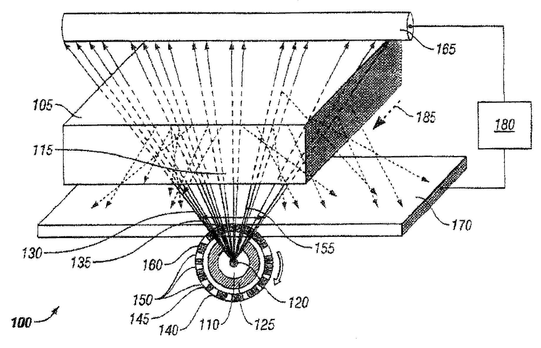
图1是根据本发明第一实施例所构造出的用于检查目标的设备的示意图,其中用调制的扇形光束来照射待检目标;Fig. 1 is a schematic diagram of a device for inspecting an object constructed according to the first embodiment of the present invention, wherein a modulated fan-shaped beam is used to irradiate the object to be inspected;
图2是一维编码图案的例子;Figure 2 is an example of a one-dimensional encoding pattern;
图3A和3B是描述在目标待检区域的照射上有效移动掩模位置的示意图;3A and 3B are schematic diagrams describing the effective movement of the mask position on the illumination of the target area to be inspected;
图4是根据本发明第二实施例所构造出的用于检查目标的设备的示意图,其中用调制的涌出光束来照射待检目标;Fig. 4 is a schematic diagram of an apparatus for inspecting an object constructed according to a second embodiment of the present invention, wherein the object to be inspected is irradiated with a modulated gushing beam;
图5是二维编码图案的例子;Fig. 5 is the example of two-dimensional coding pattern;
图6描绘出利用图5中所示编码图案的二维掩模,其可在两个正交方向中完全重叠的平移掩模;Figure 6 depicts a two-dimensional mask utilizing the encoding pattern shown in Figure 5, which can fully overlap the translation mask in two orthogonal directions;
图7是滚动类型的二维编码图案的例子;Fig. 7 is the example of the two-dimensional coding pattern of rolling type;
图8描绘出利用图7中所示编码图案的盘形可转动掩模。FIG. 8 depicts a disk-shaped rotatable mask utilizing the encoding pattern shown in FIG. 7 .
具体实施方式 Detailed ways
图1是根据本发明第一说明性实施例所构造出的用于检查目标105的设备100的示意图。设置的辐射源110用来照射目标105的待检区域115,其可以是由位置固定的x射线管120组成,能够将电子阳极斑点聚焦为足够小直径从而满足图像分辨率的要求,并位于固定光束准直仪125中。x射线管120的如此布置形成了辐射的扇形光束130,其在一个横向轴(垂至于附图的平面)上具有很窄的角色散,并且在另一横向轴135中具有宽的角色散(典型的为45到90度)。扇形光束130在图像产生处理期间为目标105的运动方向确定出平面横截,如以下将要讨论的。FIG. 1 is a schematic diagram of an
利用位于光束路径上的调制器140对扇形光束130 进行空间上的和时间上的调制。调制器140可以是可移动掩模145,由适当材料来构成,并具有适当的厚度,从而在辐射源110所发射出的波长上完全不透明,这样走向掩模145完整区域的扇形光束130的部分被目标105相应段阻挡(如这里所使用的,名词“段表示形成目标105待检区域一部分的不连续区域)。掩模145具有一系列孔或透射窗口150,使得扇形光束的一些不连续段155可露出并在掩模145的任意给定位置处照射到目标105待检区域115的相应段上。如在下文中进一步进行说明的那样,孔150的布置和尺寸大小(与邻近的掩模145的不透明区域有关)可设定为一维编码阵列160。在典型的实施中,编码阵列160具有大约是50%的开口区域,从而整个扇形光束量中的大约一半在掩模145的任意位置上是可照射到目标105上的。任意的透射探测器165,其可以是分段的或是未分段的,在目标105相对面上与扇形平面相交。在目标105的左侧设置至少一个未分段的反向散射探测器170,用于接收来自于目标105的反向散射的辐射。如这里所使用的,反向反射的辐射被认为包括由待检物体105所散射的光源辐射,既包括不相干的(如康普顿散射)也包括相干的(如雷利散射),以及在检查目标中由光源辐射所激励的原子的x射线荧光(XRF),并且该反向散射探测器170可探测这些反向散射辐射类型中的一种或多种。反向散射探测器170以及任选的透射探测器165将所接收到辐射信号的相应强度传送给处理器180,该处理器180处理信号,从而产生待检区域115的图像。反向散射探测器170优选的具有实际应用中大的有源探测区域,从而可探测到反向散射辐射的较大部分。本发明的某些实施可利用包括有两个或更多未分段的探测器的阵列;然而,与现有技术利用分段反向散射探测器的现有技术方法形成对照,待检目标图像空间分辨率并不由反向散射探测器的尺寸大小和/或数量来确定。The
掩模145可以是圆柱形(或其他连续表面,例如环形或链形),具有某一轴,掩模在不连续旋转位置的序列中绕该轴移动(分度的)。可替换的,掩模可以连续(未分度的)方式旋转。如图所示,掩模145可由任意适合的传送机构(未视出)使其受控制的旋转,例如与掩模机械联结的步进电机或音圈电机。可替换的,在通过平行与轴135的适当移动机械使其以不连续移动位置次序而渐进移动的情况中,掩模145可以是平面形状的。在掩模145中的孔150的图案使所选定的次序能够获得令人满意的图像分辨率以及信噪比。现有技术中(参看例如Gottesman等人发表于1989年Applied Optics,28(20)的4344-4352页中的“New Family ofBinary Arrays for Coded Aperture Imaging”,在此一并作为参考),详细说明了用于产生一维和二维均一冗余阵列(URA)以及改进的均一冗余阵列(MURA)的技术,其具有用于编码孔成像应用的最优性质,包括有开口区域的高分数(大约是整个区域的50%以及“么模的”解码函数,在图像区域产生均一的噪音相应。图2描绘出编码阵列160的例子,其由一组以长度为37的线性MURA图案所布置的孔150组成。具有URA和MUR图案的掩模也具有掩模图案的循环变化保持均一相应的特性。参看前面所提及的Gottesman等人所著文章,也可解释如何用各个URA或MURA来产生解码函数,以及如何向编码数据提供解码函数以产生图像。可利用产生适合的一维和/或二维编码阵列的其他方法都以在现有技术中对其进行了详细说明,这些编码阵列包括产品阵列,m序列,pn序列,以及Hadamard差集。
掩模145的位置以及尺寸大小使得在任意时刻由编码阵列160或编码阵列中的循环变化对扇形光束130进行调制。编码阵列160的长度必须与调制器140处的扇形光束130的弧度相匹配或超过其弧度。圆柱形(作为掩模145)掩模的完整旋转或平面掩模的完整平移移动可包括一个编码阵列图案或是编码阵列图案的多次重复,但至多是掩模的一个阵列长度,从而对掩模145中任意一个位置上的扇形光束130的可用部分进行编码。The
当掩模145移动时,编码阵列160以循环方式对扇形光束130进行调制,从而目标105其待检区域中的多个段根据编码序列接收到不同量的辐射。需要注意的是,空间与掩模145的阻塞(走向)通信的段可接收到少量(相对于在于孔150通信时所接收到的量)的通过临近于阻塞区域的孔150所透射过来的或是由设备100其他表面所反射或散射的乱真辐射。通过图3A和3B所图解说明的掩模145的有效移动,其描绘出当掩模145处于初始旋转位置时,在目标105(在这种情况中,构成与目标105交叉的整个扇形光束130所确定出的窄带)中待检区域的段305上所投射出的照射图案。当掩模145在一个位置处旋转移动时,如图3B中所示,在旋转方向中照射图案是前进的。目标105中待检区域上的各个段接收照射编码序列,相对于段具有与掩模145位置相符的相位移。当各个段接收到根据编码序列而变化的辐射量时,来自于目标105(例如,反向散射的和/或是透射的辐射)的旋转辐射到达反向散射探测器170以及任选的透射探测器165处,产生出代表所接收到辐射强度的信号。探测器响应被记录,用于至少一个掩模移动的完整循环,并且之后处理器180将相应的解码函数提供给各个探测器的时间相应,从而产生待检区域(例如,行扫描)的图像。目标105之后在箭头185所示方向中相对于扇形光束130的平面前进(例如,利用传送带)到新的位置,以便获得目标105中邻近区域(行扫描)的图像。可替换的照射,探测,记录,解码以及目标105前进的这几个步骤可重复执行,直到构造出目标105的完整图像。这个图像可以是,例如,在监视器上向操作者以实时显示的方式显示出来,或是为晚些时候重放和分析而将其存储起来。As the
应当理解的是,与所参考的前面提及的Callerame等人所著文献所述的方法相比,本发明的实施例为了从探测器信号中重新获得空间信息并不依赖于对于具有均一特征频率的空间变化照射序列的使用。事实上,不同端305接受照射的序列可(并且典型的是将)分享多个同频率。在这种方式下,调制器140可被视为提供光束130的非谐波调制。It should be appreciated that, in contrast to the method described in the aforementioned Callerame et al. referenced above, embodiments of the present invention do not rely on having a uniform characteristic frequency The use of spatially varying irradiation sequences. In fact, sequences of illumination at
图4描绘根据第二实施例所构造出的检查设备400,其利用了“涌出”光束(也就是,照射光束扩展为两个正交维度),而不是结合图1所述实施例中的扇形光束,并且由此利用了光源可用量的更大部分。在这个实施例中,辐射源405具有x射线管410以及在x射线管410周围布置的准直仪415,使辐射能如涌出光束420般射出,在两个正交维度中具有宽的角色散。涌出光束420穿过调制器422,包括二维掩模425,其可在两个正交轴430和435中平移(利用,例如,一个或多个与掩模425机械联结的步进电机),从而获得所需的整个完整的光束图案,并对图像进行编码。在可替换的实施中,掩模425可以是圆柱形,并且通过旋转和平移掩模来实现照射序列。具有至少一个未分段的反向散射探测器440,用于接收来自于目标450所散射的辐射。设置任选的透射探测器455,其可以是分段的也可以是未分段的,用来接收通过目标450所透射的辐射。为了产生完整的透射图像,任选的透射探测器455应足够大从而能截取整个涌出光束(然而注意,如果对向前散射的或向前发射的辐射进行探测,而不是对透射的辐射进行探测,则可利用小一些的探测器)。反向散射探测器440和任选的透射探测器455将代表了所接收到辐射强度的信号传输给处理器460,这里对信号进行处理从而产生待检区域的二维图像。如果涌出光束420的尺寸在其与目标450相交之处超过了目标450的相应尺寸(例如,如果待检区域包围整个目标450的全部),则目标450的整个图像可在目标保持固定时得到;此外,通过产生多个局部图像来产生出整个图像,其中每个局部图像实在目标450处于相对于涌出光束420不同位置处时获得的,从而对分布在目标450的整个范围上的(二维)待检区域进行扫描,之后将局部图像组织到一起,从而产生处完整图像。照射,探测,探测器响应的记录,以及二维图像的解码处理(并且,如果有必要,相对于光束重新配置目标)的次序,与在结合图1所述扇形光束系统中所使用而获得图像的次序相近似。如图1中所示的实施例,调制器422提供光束420的非谐波调制,因为设备400为了从探测器信号中重新获得空间信息并不依赖于对于具有均一特征频率的空间变化照射序列的使用。FIG. 4 depicts an
掩模425具有孔或透射窗口465的图案,确定出二维编码阵列470。编码阵列470可根据参考前面提及的Gottesman等人所著文献中所述正方形MURA方法而产生。在图5中示出了一个利用正方形MURA方法产生出的编码图案的例子。在这个情况中,可移动的掩模必须足够大从而能覆盖住阵列区域加上两个平移方向中每一个的整个重叠。由此,掩模大约是阵列区域的四倍大。图6描绘出以这种方式设计的基于图5中编码图案的掩模425。
在图4中检查设备上的变化,利用二维掩模,将其设计成仅在一个方向中平移或旋转。图7表示出用于6×6像素阵列的滚动式编码图案,可将其构造成平面矩形,连续带,或平盘形式的二维掩模。用于m乘n像素图像阵列的滚动式编码图案可由长度为l的编码序列构成,其中l大于m×n,并且主要相对于阵列宽度m。长度为l的编码序列可以是参考如前面提及Gottesman等人所述文献中所述的线性URA或线性MURA(图2描绘出这种类型的编码图案),或是具有必备特性的多个二进制序列,二进制序列的l单一循环排列组确定出l乘l矩阵,其是可以反转的,并且反转矩阵(解码矩阵)是幺模的-其所有元素具有同样的大小,不同之处仅在于标记不同。这种二进制序列可来源于二次剩余集,Hadamard差集,循环差集,孪生素数集,或伪噪序列。所形成的编码图案通过在滚动宽度m上重复提供长度为l的编码序列,对于所有l行,需要的话在下一行开始处卷绕。之后整个掩模图案具有m×l的尺寸。如果掩模并不如连续带从末端到开始而卷绕时,则第一(n-1)行必须在图案末端重复,从而调节重叠。Examine the variation on the device in Figure 4, using a 2D mask, designed to translate or rotate in only one direction. Figure 7 shows a scrolling encoding pattern for a 6x6 pixel array, which can be constructed as a two-dimensional mask in the form of a flat rectangle, continuous strip, or flat disk. A scrolling coding pattern for an m by n pixel image array may consist of coding sequences of length l, where l is greater than m x n and is primarily relative to the array width m. A coding sequence of
图8表示出盘形掩模805的设计,其为6×6像素扇区形图像阵列而使用滚动式编码图案。每个孔810的尺寸,形状以及布置是为了掩模旋转的某些不连续增量而调整与预定栅格排成直线。在整个具体设计中,所有的孔810均具有同样尺寸和形状。Figure 8 shows the design of a
所设计出在一个方向中平移和旋转的掩模易于掩模运动,该运动是连续的而不是渐进的。与辐射源和探测器连续操作相结合的连续的掩模运动,将很自然地引起沿运动方向图像出现模糊。在与掩模前进同步的不连续脉冲或脉冲串的辐射源的操作,可能会降低或消除模糊影响。可替换的,探测器可用与掩模前进同步的方式选通或关断。Masks designed to translate and rotate in one direction are prone to mask motion that is continuous rather than gradual. Continuous mask motion, combined with continuous operation of the radiation source and detector, will naturally cause blurring of the image along the direction of motion. Operation of the radiation source in discrete pulses or bursts synchronized with mask advancement may reduce or eliminate the blur effect. Alternatively, the detectors may be switched on and off synchronously with the advancement of the mask.
将要认识到的是,本发明实施例所利用的编码孔成像技术相对于其他成像技术表现出具有显著改进的信噪比(SNR)。Fenimore(发表于Applied Optics1978年17(22)的3562至3570页上的“Coded Aperture Imaging Predicted Performance ofUniformly Redundant Arrays”)介绍了一种用于计算在小孔摄像机系统等效分辨率时URA基编码孔系统的SNR(“多个优点”)改进的公式。该公式说明在等效分辨率和源强度的快速移动点系统中MURA或URA基编码光束系统的多个优点。It will be appreciated that the coded pore imaging technique utilized by embodiments of the present invention exhibits a significantly improved signal-to-noise ratio (SNR) relative to other imaging techniques. Fenimore (published in "Coded Aperture Imaging Predicted Performance of Uniformly Redundant Arrays" on pages 3562 to 3570 of Applied Optics 1978 17 (22)) introduces a method for calculating the URA base coded hole at the equivalent resolution of the small hole camera system A formula for the SNR ("multiple advantages") improvement of the system. This formulation accounts for the multiple advantages of MURA or URA base coded beam systems in fast moving point systems of equivalent resolution and source intensity.
利用非限制性例子的方式表示出上述实施例。应该注意的是发明包含任何可能的变形以及在公开实施例基础上的改变。例如,虽然所公开的实施例中利用x射线光束来检查待检目标,可替换的实施其可利用在电磁波频谱(例如,伽马射线,UV辐射,可见光)中其他位置的辐射,粒子束流(例如,中子光束),或甚至是超生波或声束。此外,可利用任何适合的装置或装置的组合来取代前面一公开的移动的掩模布设,来对光束进行空间和时间上的调制。在一个例子中,调制器可由快门孔的一维或二维阵列来组成,由此每个孔具有与之联结的快门,编程使其根据特定序列来打开和关闭。根据另一例子,掩模可被具有由辐射反射媒介(例如,热解石墨)元素所构成的图案所替代,以获得编码光束。在这种设计中,对于反射媒介来说,编码图案只不过是为掩模提供编码图案补充。在又一实施中,调制器可由可绕特定轴旋转的圆柱鼓状结构构成,具有一系列反射和非反射材料延伸的表面的鼓通常与该特定轴平行。The above-described embodiments are presented by way of non-limiting examples. It should be noted that the invention encompasses any possible variations and changes from the disclosed embodiments. For example, while the disclosed embodiment utilizes x-ray beams to inspect the object to be inspected, alternative implementations may utilize radiation elsewhere in the electromagnetic spectrum (e.g., gamma rays, UV radiation, visible light), particle beams (e.g. neutron beams), or even ultrasound or sound beams. In addition, any suitable device or combination of devices may be used instead of the previously disclosed moving mask arrangement for spatially and temporally modulating the light beam. In one example, the modulator may consist of a one-dimensional or two-dimensional array of shutter holes, whereby each hole has a shutter associated with it programmed to open and close according to a specific sequence. According to another example, the mask can be replaced by having a pattern of elements made of a radiation reflective medium (eg pyrolytic graphite) to obtain an encoded beam. In this design, the code pattern is merely a complement to the mask for the reflective media. In yet another implementation, the modulator may consist of a cylindrical drum-like structure rotatable about a particular axis generally parallel to which the drum has a series of extending surfaces of reflective and non-reflective material.
对于某种特定类型的照射光束,将调制器与辐射源整合在一起是有利的。在这种集成结构的一个例子中,源/调制器可由辐射发射器阵列组成,每个发射器的输出将被独立调制(以与LED投影器类似的方式),从而合成光束在任意给定时刻均具有规定的空间分布。For certain types of illumination beams, it may be advantageous to integrate the modulator with the radiation source. In one example of such an integrated structure, the source/modulator could consist of an array of radiating emitters, the output of each emitter would be independently modulated (in a similar manner to an LED projector), so that the combined beam would at any given moment have a defined spatial distribution.
根据本发明的另一实施,用于形成辐射光束的准直仪结构可位于调制器(例如,可移动掩模)与待检目标之间,而不是位于x射线管与调制器之间(如图1和4中所示)。According to another implementation of the invention, the collimator structure used to form the radiation beam may be located between the modulator (e.g. a movable mask) and the object to be inspected instead of between the x-ray tube and the modulator (e.g. shown in Figures 1 and 4).
如前面所注意的,术语“反向散射辐射”意欲包括由待检目标所散射的光源辐射,既包括不相干的(Compton散射)又包括相干的(Rayleigh散射),以及在待检物体中由于光源辐射所激励的原子的x射线荧光(XRF)。如果反向散射探测器配备有能量扩散能力或能量选择筛选能力,则原则上可能对待检目标表面内或上的特定化学元素或元素组进行选择性成像。利用可移动编码掩模对光源照射进行编码以及随后从所探测到的信号中解码出图像的方法,对于成像XRF系统来说与前面所述编码光束系统保持相同。还要注意的是,在本发明的某些实施例中,一个或多个探测器设置在目标的远侧(例如,在与源和调制器的相对的面上),用以在前进方向中接收和探测来自于待检目标所散射的辐射(包括有经由XRF由目标所发射出的辐射)。这个说明中的探测器也可配备有能量能量扩散能力或能量选择筛选能力,用来对待检目标表面内或上的特定化学元素或元素组进行选择性成像As previously noted, the term "backscattered radiation" is intended to include source radiation scattered by the object under examination, both incoherent (Compton scatter) and coherent (Rayleigh scatter), as well as in the object under examination due to The light source radiates x-ray fluorescence (XRF) of the excited atoms. If the backscatter detector is equipped with energy dispersive or energy selective screening capabilities, it is in principle possible to selectively image specific chemical elements or groups of elements in or on the surface of the target to be examined. The method of encoding the source illumination using the movable encoding mask and subsequently decoding the image from the detected signal remains the same for the imaging XRF system as previously described for the encoded beam system. Note also that in some embodiments of the invention, one or more detectors are positioned on the far side of the target (e.g., on the face opposite the source and modulator) for Receive and detect radiation scattered from the target to be inspected (including radiation emitted by the target via XRF). The detectors in this description can also be equipped with energy energy dispersive capability or energy selective screening capability for selective imaging of specific chemical elements or groups of elements in or on the surface of the target to be examined
在特定实施中,为了减小孔的尺寸并供给关注目标的原地检查,可预期其组合了检查设备中公共包含的两个或更多部件,例如汽车或集装箱。在一个例子中,便携式检查设备可通过将光源,调制器,探测器和处理器部件集成到一个外壳内而构造出来。In certain implementations, it is contemplated to combine two or more components commonly contained in inspection equipment, such as automobiles or shipping containers, in order to reduce the size of the holes and provide for in situ inspection of objects of interest. In one example, a portable inspection device can be constructed by integrating light source, modulator, detector and processor components into one housing.
通常可以理解的是已结合某些说明性实施例的详细说明对本发明进行了说明,前面所述内容意欲说明而并非限制本发明的范围,本发明的范围是由其权利要求所限定出来的。其他方面,优点以及变形包括权利要求的范围内。It will be generally understood that the invention has been described in conjunction with the detailed description of certain illustrative embodiments, and that the foregoing is intended to illustrate, not to limit, the scope of the invention, which is defined by the claims. Other aspects, advantages, and modifications are within the scope of the claims.
Claims (25)
Applications Claiming Priority (2)
| Application Number | Priority Date | Filing Date | Title |
|---|---|---|---|
| US85387606P | 2006-10-24 | 2006-10-24 | |
| US60/853,876 | 2006-10-24 |
Publications (1)
| Publication Number | Publication Date |
|---|---|
| CN101568855A true CN101568855A (en) | 2009-10-28 |
Family
ID=39864530
Family Applications (1)
| Application Number | Title | Priority Date | Filing Date |
|---|---|---|---|
| CNA2007800396990A Pending CN101568855A (en) | 2006-10-24 | 2007-10-24 | Apparatus for inspecting objects using coded beam |
Country Status (7)
| Country | Link |
|---|---|
| US (1) | US7623614B2 (en) |
| EP (1) | EP2076793B1 (en) |
| JP (1) | JP2010507811A (en) |
| CN (1) | CN101568855A (en) |
| AU (1) | AU2007351440B2 (en) |
| CA (1) | CA2665872C (en) |
| WO (1) | WO2008127385A2 (en) |
Cited By (8)
| Publication number | Priority date | Publication date | Assignee | Title |
|---|---|---|---|---|
| CN103983654A (en) * | 2014-05-26 | 2014-08-13 | 中国科学院高能物理研究所 | Ray scattering imaging system based on aperture coding technique |
| CN108646260A (en) * | 2018-07-02 | 2018-10-12 | 中国科学院西安光学精密机械研究所 | Staring type lens-free laser three-dimensional imaging device and imaging method |
| CN109691238A (en) * | 2016-07-14 | 2019-04-26 | 拉皮斯坎系统股份有限公司 | System and method for improving penetration of radiographic scanners |
| CN113466956A (en) * | 2021-06-18 | 2021-10-01 | 南京航空航天大学 | Encrypted radiation imaging system based on random thickness liquid mask |
| CN113710160A (en) * | 2019-02-18 | 2021-11-26 | 阿戈斯佩技术公司 | Collimator for medical imaging system and image reconstruction method thereof |
| CN113758952A (en) * | 2021-08-20 | 2021-12-07 | 中国科学院上海光学精密机械研究所 | X-ray diffraction imaging device and method based on momentum coding |
| CN115266730A (en) * | 2022-07-27 | 2022-11-01 | 凌云光技术股份有限公司 | A defect detection method and device based on snapshot compression imaging |
| CN115753860A (en) * | 2022-11-15 | 2023-03-07 | 南京航空航天大学 | Element distribution imaging device and method based on rotary modulation collimator |
Families Citing this family (47)
| Publication number | Priority date | Publication date | Assignee | Title |
|---|---|---|---|---|
| US20080253653A1 (en) * | 2007-04-12 | 2008-10-16 | Todd Gable | Systems and methods for improving visibility of scanned images |
| WO2008134757A1 (en) * | 2007-04-30 | 2008-11-06 | University Of Florida Research Foundation, Inc. | Method and apparatus for shadow aperture backscatter radiography (sabr) system and protocol |
| US8243353B1 (en) | 2008-04-07 | 2012-08-14 | Applied Science Innovations, Inc. | Holography-based device, system and method for coded aperture imaging |
| GB0823093D0 (en) * | 2008-12-19 | 2009-01-28 | Durham Scient Crystals Ltd | Apparatus and method for characterisation of materials |
| CN102365703A (en) * | 2009-03-27 | 2012-02-29 | 皇家飞利浦电子股份有限公司 | Structured electron emitter for coded source imaging with an x-ray tube |
| US8304737B2 (en) * | 2009-10-02 | 2012-11-06 | Ut-Battelle, Llc | Apparatus and method to achieve high-resolution microscopy with non-diffracting or refracting radiation |
| US9421692B2 (en) | 2010-05-14 | 2016-08-23 | Automated Vision, Llc | Methods and computer program products for processing of coverings such as leather hides and fabrics for furniture and other products |
| US9157182B2 (en) * | 2010-05-14 | 2015-10-13 | Automated Vision, Llc | Systems, methods and computer program products for processing of coverings such as leather hides and fabrics for furniture and other products |
| WO2012054381A1 (en) * | 2010-10-18 | 2012-04-26 | American Science And Engineering, Inc. | System and methods for intrapulse multi-energy and adaptive multi-energy x-ray cargo inspection |
| DE102010061182B4 (en) * | 2010-12-13 | 2013-02-07 | Presens Precision Sensing Gmbh | Sensor arrangement, method and measuring system for detecting the distribution of at least one variable of an object |
| WO2013103408A1 (en) * | 2011-10-07 | 2013-07-11 | Duke University | Apparatus for coded aperture x-ray scatter imaging and method therefor |
| FR2981455B1 (en) * | 2011-10-14 | 2013-12-27 | Commissariat Energie Atomique | PORTABLE AND VERSATILE X OR GAMMA IMAGING DEVICE FOR THE NON-DESTRUCTIVE EXAMINATION OF SUSPECTED PACKAGES, INTEGRATING IMAGING TECHNIQUES IN TRANSMISSION AND RETROSPECTING |
| US8971484B2 (en) * | 2011-11-22 | 2015-03-03 | Xinray Systems Inc | High speed, small footprint x-ray tomography inspection systems, devices, and methods |
| RU2606698C2 (en) * | 2012-02-14 | 2017-01-10 | Американ Сайенс Энд Инжиниринг, Инк. | X-ray examination using fibre scintillation detectors with wavelengths shift |
| WO2013184213A2 (en) * | 2012-05-14 | 2013-12-12 | The General Hospital Corporation | A distributed, field emission-based x-ray source for phase contrast imaging |
| US8879688B2 (en) * | 2012-05-22 | 2014-11-04 | The Boeing Company | Reconfigurable detector system |
| JP6202484B2 (en) * | 2012-08-10 | 2017-09-27 | 国立研究開発法人物質・材料研究機構 | Neutron imaging device and method of using the same |
| WO2014034244A1 (en) * | 2012-08-27 | 2014-03-06 | ソニー株式会社 | X-ray output apparatus |
| FR3000211B1 (en) | 2012-12-20 | 2015-12-11 | Commissariat Energie Atomique | SCANNING LIGHTING DEVICE, IMAGING DEVICE COMPRISING SAME, AND METHOD FOR OPERATING SAME |
| WO2014121039A1 (en) * | 2013-01-31 | 2014-08-07 | Duke University | System for improved compressive tomography and method therefor |
| EP2976626A4 (en) * | 2013-03-22 | 2016-09-21 | Univ New York | SYSTEM, METHOD AND COMPUTER-ACCESSIBLE MEDIUM FOR MODULATION OF INTENSITY OF X-RAY BEAM |
| US10107768B2 (en) | 2013-08-13 | 2018-10-23 | Duke University | Volumetric-molecular-imaging system and method therefor |
| US9934930B2 (en) | 2014-04-18 | 2018-04-03 | Fei Company | High aspect ratio x-ray targets and uses of same |
| LT3146527T (en) * | 2014-05-22 | 2022-02-25 | Australian Nuclear Science & Technology Organisation | Gamma-ray imaging |
| CN104267053A (en) * | 2014-09-30 | 2015-01-07 | 包微微 | Novel detector for liquid prohibited articles |
| CN106331442B (en) * | 2015-07-02 | 2021-01-15 | 松下知识产权经营株式会社 | Image pickup apparatus |
| CN105301669B (en) * | 2015-12-04 | 2019-01-04 | 同方威视技术股份有限公司 | Rays safety detection apparatus and X-ray detection X method |
| JP6738644B2 (en) | 2016-04-15 | 2020-08-12 | 三星電子株式会社Samsung Electronics Co.,Ltd. | Imaging device and imaging method |
| US10753869B2 (en) * | 2016-07-29 | 2020-08-25 | William Marsh Rice University | Lensless imaging device for microscopy and fingerprint biometric |
| JP6395275B2 (en) * | 2017-04-13 | 2018-09-26 | 国立研究開発法人物質・材料研究機構 | X-ray imaging apparatus and method of using the same |
| DE102017111215B4 (en) * | 2017-05-23 | 2024-02-08 | Infineon Technologies Ag | Device and method for detecting a property from electromagnetic radiation sensor data |
| WO2019006310A1 (en) * | 2017-06-29 | 2019-01-03 | Cuadros Angela | Pixelated k-edge coded aperture system for compressive spectral x-ray imaging |
| CN111226141B (en) | 2017-10-20 | 2023-12-26 | 澳大利亚核科学和技术组织 | Compressed imaging methods and systems |
| CN108227027B (en) * | 2017-12-29 | 2020-12-01 | 同方威视技术股份有限公司 | Vehicle Backscatter Inspection System |
| CN108008458B (en) * | 2017-12-29 | 2020-09-08 | 同方威视技术股份有限公司 | Vehicle-mounted backscatter inspection system |
| CN108490497B (en) * | 2018-02-05 | 2024-03-22 | 清华大学 | Security inspection system and method |
| CN109273131B (en) * | 2018-10-31 | 2024-07-02 | 同方威视技术股份有限公司 | Collimator assembly and radiation detection device |
| US10948614B2 (en) | 2018-11-01 | 2021-03-16 | H3D, Inc. | Imaging system with one or more mask units and corresponding method of recording radiation |
| US11399788B2 (en) * | 2019-01-15 | 2022-08-02 | Duke University | Systems and methods for tissue discrimination via multi-modality coded aperture x-ray imaging |
| CN114930466B (en) * | 2019-08-02 | 2025-05-27 | 维德雷技术公司 | Enclosed X-ray Chopper Wheel |
| CA3200719A1 (en) * | 2020-11-21 | 2022-05-27 | Bar Ilan University | System and method for mapping chemical elements in a sample |
| US11701077B2 (en) * | 2021-02-25 | 2023-07-18 | Uchicago Argonne, Llc | Coded-mask-based X-ray phase-contrast and dark-field imaging |
| EP4377680A4 (en) * | 2021-07-28 | 2025-09-24 | Univ Bar Ilan | Method and system for imaging high photon energies |
| KR102810542B1 (en) * | 2023-01-09 | 2025-05-26 | 제주대학교 산학협력단 | Method for measuring radiation dose rate using a coded-aperture based hand-held dual particle imager |
| CN116125517B (en) * | 2023-02-13 | 2025-06-17 | 成都理工大学 | Single-pixel radiation imaging method and system based on rotation measurement |
| US12422384B2 (en) | 2023-04-29 | 2025-09-23 | Videray Technologies, Inc. | Handheld x-ray system including a stand-alone detector panel |
| CN116660297A (en) * | 2023-06-28 | 2023-08-29 | 北京亿特克科技有限公司 | A self-correction-based X-ray encoding imaging method and device |
Family Cites Families (25)
| Publication number | Priority date | Publication date | Assignee | Title |
|---|---|---|---|---|
| US3749911A (en) * | 1970-06-30 | 1973-07-31 | Nasa | Collimator of multiple plates with axially aligned identical random arrays of apertures |
| DE2756659A1 (en) * | 1977-12-19 | 1979-06-21 | Philips Patentverwaltung | ARRANGEMENT FOR DETERMINING THE ABSORPTION DISTRIBUTION |
| US4209780A (en) * | 1978-05-02 | 1980-06-24 | The United States Of America As Represented By The United States Department Of Energy | Coded aperture imaging with uniformly redundant arrays |
| US4360797A (en) * | 1978-05-02 | 1982-11-23 | The United States Of America As Represented By The United States Department Of Energy | Coded aperture imaging with uniformly redundant arrays |
| US4392237A (en) * | 1980-08-25 | 1983-07-05 | General Electric Company | Scanning x-ray inspection system |
| US4389633A (en) * | 1980-09-26 | 1983-06-21 | The United States Of America As Represented By The United States Department Of Energy | Coded aperture imaging with self-supporting uniformly redundant arrays |
| US4506374A (en) * | 1982-04-08 | 1985-03-19 | Technicare Corporation | Hybrid collimator |
| JPS61249452A (en) * | 1985-04-30 | 1986-11-06 | 株式会社東芝 | X-ray diagnostic apparatus |
| US5098640A (en) * | 1990-01-10 | 1992-03-24 | Science Applications International Corporation | Apparatus and method for detecting contraband using fast neutron activation |
| US5606165A (en) * | 1993-11-19 | 1997-02-25 | Ail Systems Inc. | Square anti-symmetric uniformly redundant array coded aperture imaging system |
| US5666393A (en) * | 1994-02-17 | 1997-09-09 | Annis; Martin | Method and apparatus for reducing afterglow noise in an X-ray inspection system |
| WO1997045755A1 (en) * | 1996-05-31 | 1997-12-04 | Massachusetts Institute Of Technology | Coded aperture imaging |
| WO1998020366A1 (en) * | 1996-11-08 | 1998-05-14 | American Science And Engineering, Inc. | Coded aperture x-ray imaging system |
| EP0916981B1 (en) * | 1997-11-17 | 2004-07-28 | Max-Planck-Gesellschaft zur Förderung der Wissenschaften e.V. | Confocal spectroscopy system and method |
| US6453007B2 (en) * | 1998-11-30 | 2002-09-17 | American Science And Engineering, Inc. | X-ray inspection using co-planar pencil and fan beams |
| EP1135700B1 (en) * | 1998-11-30 | 2005-03-02 | American Science & Engineering, Inc. | Fan and pencil beams from a common source for x-ray inspection |
| US6353227B1 (en) * | 1998-12-18 | 2002-03-05 | Izzie Boxen | Dynamic collimators |
| US6269142B1 (en) * | 1999-08-11 | 2001-07-31 | Steven W. Smith | Interrupted-fan-beam imaging |
| WO2001094984A2 (en) * | 2000-06-07 | 2001-12-13 | American Science And Engineering, Inc. | X-ray scatter and transmission system with coded beams |
| GB0019451D0 (en) * | 2000-08-09 | 2000-09-27 | Secr Defence | Imaging apparatus |
| WO2002056055A2 (en) * | 2000-09-29 | 2002-07-18 | Massachusetts Inst Technology | Systems and methods for coded aperture imaging of radiation- emitting sources |
| JP4022385B2 (en) * | 2001-10-29 | 2007-12-19 | 三井造船株式会社 | Radiation detector |
| CA2427463A1 (en) * | 2003-04-30 | 2004-10-30 | Her Majesty The Queen, In Right Of Canada, As Represented By The Minister Of National Defence | Detection of explosive devices using x-ray backscatter radiation |
| US6950495B2 (en) * | 2003-12-01 | 2005-09-27 | The Boeing Company | Backscatter imaging using Hadamard transform masking |
| EP1740097A1 (en) * | 2004-04-21 | 2007-01-10 | Philips Intellectual Property & Standards GmbH | Fan-beam coherent-scatter computer tomograph |
-
2007
- 2007-10-24 CN CNA2007800396990A patent/CN101568855A/en active Pending
- 2007-10-24 CA CA2665872A patent/CA2665872C/en active Active
- 2007-10-24 AU AU2007351440A patent/AU2007351440B2/en active Active
- 2007-10-24 US US11/923,532 patent/US7623614B2/en active Active
- 2007-10-24 JP JP2009534843A patent/JP2010507811A/en active Pending
- 2007-10-24 EP EP07873569.3A patent/EP2076793B1/en active Active
- 2007-10-24 WO PCT/US2007/082428 patent/WO2008127385A2/en not_active Ceased
Cited By (13)
| Publication number | Priority date | Publication date | Assignee | Title |
|---|---|---|---|---|
| CN103983654B (en) * | 2014-05-26 | 2016-09-14 | 中国科学院高能物理研究所 | A kind of ray scattering imaging system based on aperture coding techniques |
| CN103983654A (en) * | 2014-05-26 | 2014-08-13 | 中国科学院高能物理研究所 | Ray scattering imaging system based on aperture coding technique |
| CN109691238A (en) * | 2016-07-14 | 2019-04-26 | 拉皮斯坎系统股份有限公司 | System and method for improving penetration of radiographic scanners |
| CN109691238B (en) * | 2016-07-14 | 2024-02-13 | 拉皮斯坎系统股份有限公司 | System and method for improving penetration of a radiological imaging scanner |
| CN108646260B (en) * | 2018-07-02 | 2024-01-05 | 中国科学院西安光学精密机械研究所 | Staring type lens-free laser three-dimensional imaging device and imaging method |
| CN108646260A (en) * | 2018-07-02 | 2018-10-12 | 中国科学院西安光学精密机械研究所 | Staring type lens-free laser three-dimensional imaging device and imaging method |
| CN113710160A (en) * | 2019-02-18 | 2021-11-26 | 阿戈斯佩技术公司 | Collimator for medical imaging system and image reconstruction method thereof |
| CN113466956A (en) * | 2021-06-18 | 2021-10-01 | 南京航空航天大学 | Encrypted radiation imaging system based on random thickness liquid mask |
| CN113758952A (en) * | 2021-08-20 | 2021-12-07 | 中国科学院上海光学精密机械研究所 | X-ray diffraction imaging device and method based on momentum coding |
| CN113758952B (en) * | 2021-08-20 | 2022-10-11 | 中国科学院上海光学精密机械研究所 | X-ray diffraction imaging device and method based on momentum coding |
| CN115266730A (en) * | 2022-07-27 | 2022-11-01 | 凌云光技术股份有限公司 | A defect detection method and device based on snapshot compression imaging |
| CN115753860A (en) * | 2022-11-15 | 2023-03-07 | 南京航空航天大学 | Element distribution imaging device and method based on rotary modulation collimator |
| CN115753860B (en) * | 2022-11-15 | 2025-04-11 | 南京航空航天大学 | Element distribution imaging device and method based on rotation modulation collimator |
Also Published As
| Publication number | Publication date |
|---|---|
| WO2008127385A2 (en) | 2008-10-23 |
| EP2076793A2 (en) | 2009-07-08 |
| AU2007351440B2 (en) | 2012-12-06 |
| JP2010507811A (en) | 2010-03-11 |
| CA2665872A1 (en) | 2008-10-23 |
| EP2076793B1 (en) | 2016-01-06 |
| CA2665872C (en) | 2013-04-02 |
| US7623614B2 (en) | 2009-11-24 |
| AU2007351440A1 (en) | 2008-10-23 |
| US20080095298A1 (en) | 2008-04-24 |
| WO2008127385A3 (en) | 2009-07-16 |
Similar Documents
| Publication | Publication Date | Title |
|---|---|---|
| CN101568855A (en) | Apparatus for inspecting objects using coded beam | |
| US6470067B1 (en) | Computed tomography apparatus for determining the pulse momentum transfer spectrum in an examination zone | |
| KR101504491B1 (en) | X-ray image acquisition device and X-ray image acquisition method, sensor and imaging device | |
| JP2021518217A (en) | X-ray tomography | |
| CN101512379B (en) | Acquisition and reconstruction of projection data using a stationary ct geometry | |
| WO2003105159A1 (en) | Scanner for x-ray inspection comprising a chopper wheel with differently sized apertures | |
| US9557284B2 (en) | Scanning illuminating device, imaging device comprising same and method of implementation | |
| WO2008018021A2 (en) | System and method for acquiring image data | |
| WO1998033076A1 (en) | Radiation imaging using simultaneous emission and transmission | |
| CN102065771B (en) | Medical X-ray examination apparatus and method for k-edge imaging | |
| CN110308614B (en) | Method and apparatus for X-ray intensity correlated imaging | |
| CA2951639C (en) | Methods for 2-color radiography with laser-compton x-ray sources | |
| CN1584566A (en) | Device for capturing structural data of an object | |
| EP1307766B8 (en) | Apparatus for imaging objects on the remote side of a barrier using radiation | |
| US20070133741A1 (en) | Computed examination of an object by using coherent-scattered radiation | |
| Liu et al. | A novel method of coded-aperture push-broom compton scatter imaging: Principles, simulations and experiments | |
| AU2001276490A1 (en) | Apparatus for imaging objects on the remote side of a barrier using radiation | |
| EP2749901B1 (en) | Back-scattering inspection systems and methods for human body | |
| JP2012110579A (en) | Radiation tube device and radiation imaging system | |
| GB1584954A (en) | Radiography | |
| JP2004045247A (en) | X-ray image inspection device | |
| Grubsky et al. | Compton tomography system |
Legal Events
| Date | Code | Title | Description |
|---|---|---|---|
| C06 | Publication | ||
| PB01 | Publication | ||
| C10 | Entry into substantive examination | ||
| SE01 | Entry into force of request for substantive examination | ||
| C02 | Deemed withdrawal of patent application after publication (patent law 2001) | ||
| WD01 | Invention patent application deemed withdrawn after publication |
Application publication date: 20091028 |