CN101557978A - Self-propelled vehicle propelled by an elliptical drive train - Google Patents
Self-propelled vehicle propelled by an elliptical drive train Download PDFInfo
- Publication number
- CN101557978A CN101557978A CNA2007800430116A CN200780043011A CN101557978A CN 101557978 A CN101557978 A CN 101557978A CN A2007800430116 A CNA2007800430116 A CN A2007800430116A CN 200780043011 A CN200780043011 A CN 200780043011A CN 101557978 A CN101557978 A CN 101557978A
- Authority
- CN
- China
- Prior art keywords
- pin
- guide rail
- attaching parts
- equipment
- pin attaching
- Prior art date
- Legal status (The legal status is an assumption and is not a legal conclusion. Google has not performed a legal analysis and makes no representation as to the accuracy of the status listed.)
- Pending
Links
Images


Landscapes
- Handcart (AREA)
Abstract
Description
发明领域field of invention
本发明大体上涉及脚踏车。更具体地,本发明有关于具有椭圆传动系统的脚踏车。The present invention generally relates to bicycles. More specifically, the present invention relates to bicycles having elliptical drive trains.
发明背景Background of the invention
最普通的人力驱动车辆是脚踏车。熟知的是脚踏车在锻炼、娱乐以及交通方面的应用。常规脚踏车的操纵者处于坐立姿态,并且进行基本上为圆形的运动以便做出推进脚踏车所需的机械功。在操纵过程中,操纵者的上体通常在腰部向前弯曲,并由臂部、肩部、腹部和下背部的肌肉保持就位。这种最普通的骑行姿态使人较有压力。骑脚踏车者经常会感到因坐在脚踏车的座椅或“鞍座”上而引起的骨盆区的疼痛、不适,和/或麻木,以及因俯身骑行姿态所引起的下背部、臂部和肩部的不适。The most common human-powered vehicle is the bicycle. Well known are the uses of bicycles for exercise, recreation, and transportation. The rider of a conventional cycle is in a seated position and makes a substantially circular motion in order to perform the mechanical work required to propel the cycle. During manipulation, the manipulator's upper body is usually bent forward at the waist and held in place by muscles in the arms, shoulders, abdomen, and lower back. This most common riding posture makes people more stressed. Cyclists often experience pain, discomfort, and/or numbness in the pelvic area from sitting on the seat or "saddle" of their bicycle, as well as pain, discomfort, and/or numbness in the lower back, arms, and Discomfort in the shoulder.
为了减轻与长期使用常规脚踏车相关的不适,出现了斜躺式脚踏车(recumbent bicycles),在这种斜躺式脚踏车中,操纵者在斜躺的姿态下来推进脚踏车。尽管斜躺式脚踏车减轻了大部分与常规脚踏车相关的不适,但是斜躺的骑行姿态使这种脚踏车不够稳定并且更难于骑行。斜躺脚踏车还被受限于通勤车量,因为低至地面的构造使障碍物容易阻碍操纵者的视线,并使他或她不易于被其它车辆、骑脚踏车者和行人所看到。另外,由于常规的脚踏车和斜躺式脚踏车的操纵者是处于坐立姿态的,因此操纵者在操纵这种车辆时不会得到负重练习所带来的肌肉与骨骼方面的益处。To alleviate the discomfort associated with long-term use of conventional bicycles, recumbent bicycles have emerged in which the operator propels the bicycle in a recumbent position. Although recumbent bikes alleviate much of the discomfort associated with regular bikes, the recumbent riding position makes such bikes less stable and more difficult to ride. Recumbent bikes are also limited in commuter volume because the low-to-the-ground configuration makes it easy for obstacles to obstruct the operator's view and make him or her less visible to other vehicles, cyclists, and pedestrians. In addition, because the rider of conventional bicycles and recumbent bikes is in a sitting position, the rider does not get the musculoskeletal benefits of weight-bearing exercises when maneuvering such vehicles.
因此,需要克服上述现有技术中的一个或多个局限。Accordingly, there is a need to overcome one or more of the limitations of the prior art described above.
附图说明 Description of drawings
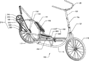
图1示出了脚踏车的一个实施方式的立体图;Figure 1 shows a perspective view of an embodiment of a bicycle;
图2示出了图1的脚踏车的侧视图,其示意性地显示了椭圆脚踏轮廓;Figure 2 shows a side view of the cycle of Figure 1, schematically showing an elliptical pedal profile;
图3示出了图1的脚踏车的侧视图,其示意性地显示了操纵者区;Figure 3 shows a side view of the cycle of Figure 1, schematically showing the operator's area;
图4示出了脚踏车的另一个实施方式的立体图;Figure 4 shows a perspective view of another embodiment of the bicycle;
图5示出了脚踏车的又一个实施方式的立体图;Figure 5 shows a perspective view of yet another embodiment of the bicycle;
图6示出了脚踏车的又一个实施方式的立体图;Figure 6 shows a perspective view of yet another embodiment of the bicycle;
图7示出了包括可调导轨的脚踏车的又一个实施方式;Figure 7 shows yet another embodiment of a cycle comprising adjustable rails;
图8示出了可连接至脚踏车的可调曲柄臂的局部立体图;Figure 8 shows a partial perspective view of an adjustable crank arm attachable to a bicycle;
图9A示出了可连接至脚踏车的可调脚平台的一个实施方式的立体图;Figure 9A shows a perspective view of one embodiment of an adjustable foot platform connectable to a bicycle;
图9B示出了可连接至脚踏车的可调脚平台的另一个实施方式的立体图;Figure 9B shows a perspective view of another embodiment of an adjustable foot platform attachable to a bicycle;
图10A-L示出了可连接至脚踏车的承载轮保持装置的不同的实施方式的侧视图;Figures 10A-L show side views of different embodiments of a load wheel retaining device attachable to a bicycle;
图11示出了可连接至脚踏车的可调转向管件的一个实施方式的立体图;Figure 11 shows a perspective view of one embodiment of an adjustable steering tube connectable to a bicycle;
图12示出了可连接至脚踏车的直接传动系统的一个实施方式的立体图;Figure 12 shows a perspective view of one embodiment of a direct drive system connectable to a bicycle;
图13A示出了包括可折叠框架的脚踏车的另一个实施方式的立体图;Figure 13A shows a perspective view of another embodiment of a cycle comprising a collapsible frame;
图13B示出了图13A中所示的脚踏车在被折叠后的立体图;以及Figure 13B shows a perspective view of the bicycle shown in Figure 13A after being folded; and
图14示出了脚踏车的又一个实施方式的立体图。Figure 14 shows a perspective view of yet another embodiment of a bicycle.
要认识到,附图中部分或全部是用于说明目的的示意性表示,而并不一定显示了所示元件的实际相对大小或位置。所提供的附图用于对脚踏车的一个或多个实施方式进行说明,并清楚地表明这些附图并非用于限制权利要求范围或内涵。It is to be appreciated that some or all of the drawings are schematic representations for illustrative purposes and do not necessarily show the actual relative sizes or positions of the elements shown. The drawings are provided to illustrate one or more embodiments of the cycle and are expressly intended not to limit the scope or meaning of the claims.
优选实施方式preferred embodiment
出于解释的目的,在以下描述中,阐述了大量的具体细节以便提供对本发明的脚踏车透彻理解。但是,可在缺少部分的这些细节的情况下实施脚踏车对本领域内的技术人员是显而易见的。例如,可以采用多种承载轮保持装置。在整个说明书中,所示的实施方式和示例应被认为是样例,而不是对脚踏车的限制。即,出于说明的目的,以下描述提供了示例,而附图则示出了各种示例。然而,这些示例不应解释成具有限制的意义,因为这些示例仅是要提供脚踏车的示例而不是要穷尽地列出脚踏车的所有可能的实施方式。For purposes of explanation, in the following description, numerous specific details are set forth in order to provide a thorough understanding of the cycle of the present invention. However, it will be apparent to those skilled in the art that a bicycle may be implemented without some of these details. For example, a variety of load wheel retention arrangements may be employed. Throughout the specification, the embodiments and examples shown should be considered exemplars, not limitations of the bicycle. That is, the following description provides examples for the purpose of explanation, and the drawings show various examples. However, these examples should not be construed in a limiting sense, as these examples are intended to provide examples of bicycles rather than an exhaustive list of all possible implementations of bicycles.
本发明的公开大体上涉及人力驱动的运输工具,更具体地涉及由椭圆脚踏运动驱动的运输、锻炼和娱乐车辆,这种椭圆脚踏运动大体上模仿行走或奔跑的运动。本文所描述的设备的一个实施方式是脚踏车,其提供了改进的人力驱动的运输工具,这种改进的运输工具具有优于常规脚踏车、踏板车、直立脚踏单车和其它人力驱动车辆的优点。The present disclosure relates generally to human-powered vehicles, and more particularly to transportation, exercise and recreational vehicles powered by elliptical pedaling motions that generally mimic the motion of walking or running. One embodiment of the devices described herein is a bicycle, which provides an improved human-powered vehicle with advantages over conventional bicycles, scooters, upright cycles, and other human-powered vehicles.
本文将“脚踏车”限定为至少部分地由作用在踏板上的脚或手的形式的人力来驱动的、具有至少两个轮子的、除踏板车和类似装置(限定为被接触地面的脚操纵的车辆)之外的所有车辆。术语“脚踏车”还包括三轮和四轮人力驱动的车辆。A "cycle" is defined herein as a vehicle having at least two wheels that is propelled at least in part by human power in the form of feet or hands acting on pedals, except scooters and similar vehicles) other than vehicles). The term "bicycle" also includes three- and four-wheel human-powered vehicles.
更具体地,本文公开了由大体上模仿奔跑或行走运动学的椭圆脚踏运动驱动的低交叠高度脚踏车,并提供了一种人力驱动运输工具,这种车辆具有优于常规的直立脚踏单车、脚踏车和踏板车的优点。本文还公开了使操纵者能够调整这种车辆的脚踏轮廓的方法。More specifically, this document discloses a low-overlap cycle powered by an elliptical pedal motion that substantially mimics the kinematics of running or walking, and provides a human-powered vehicle that has advantages over conventional upright pedals. The advantages of bicycles, bicycles and scooters. Also disclosed herein is a method of enabling an operator to adjust the pedal profile of such a vehicle.
直立脚踏单车虽然在现有技术中是已知的,但是仍具有一些缺陷。例如,某些所述的直立脚踏单车的轴距长度限制了可用如乘用车的其它车辆将其运输的手段,并且在操纵者没有拆卸这种单车的情况下阻碍将这种单车在狭窄的脚踏车道或街道中转向。常规的直立脚踏单车还具有靠近操纵者布置的链轮和链条。这些运动的部件如果被触碰,那么就会损坏操纵者的衣物和/或伤害操纵者。另外,以下会详细地讨论,常规的直立脚踏单车具有将支撑结构定位在操纵者区中的框架。如果操纵者在骑行或在跌落过程中触碰了位于操纵者区中的框架构件,那么他或她可能会被这种框架构件伤害。位于操纵者区中的框架构架还使车辆的安装和拆卸更加困难。Upright bicycles, although known in the art, still have some drawbacks. For example, the wheelbase length of some of the described upright bicycles limits the means by which they can be transported by other vehicles, such as passenger vehicles, and prevents the use of such bicycles in tight spaces without the operator dismantling them. turn in a cycle path or street. Conventional upright bicycles also have sprockets and chains positioned close to the operator. These moving parts, if touched, can damage the operator's clothing and/or injure the operator. Additionally, as discussed in detail below, conventional upright bicycles have a frame that positions the support structure in the rider's area. If a rider touches a frame member located in the rider zone while riding or falling, he or she may be injured by such a frame member. The frame frame located in the operator's area also makes installation and removal of the vehicle more difficult.
另外,常规的直立脚踏单车缺乏某些特征,这些特征可以使操纵者能够容易地修改车辆的脚踏轮廓,因而允许对单一车辆进行调整以适应多种不同身材的骑行者。如以上所讨论的那样,操纵者在车辆上脚踏过程中的脚所采取的运动线路大体上是椭圆。相对用于推进常规的脚踏车或斜躺式脚踏车的圆形运动,某些人更喜欢这种大体上为椭圆的运动,因为这种大体上为椭圆的运动更好地模仿了行走、奔跑或攀登,并且对于增强腿部肌肉而言,这种大体上为椭圆的运动相比骑行已经表现为更加有效的手段,同时还避免了由奔跑产生的压力和冲击。然而,由于脚踏运动模仿人类的运动,因而具有不同解剖学尺寸的操纵者大体上会需要不同的脚踏轮廓。具体地,相比于较矮的操纵者,较高的操纵者可能会需要具有较长步长的脚踏轮廓。另外,更进取的操纵者可能会喜欢更陡的脚平台起动角(take-off angle),从而他或她会产生更低的力矩,而不太进取的骑行者可能会喜欢更扁平的脚踏轮廓以减小脚踏行程中的脚弯曲和膝弯曲。Additionally, conventional upright bicycles lack certain features that would allow a rider to easily modify the pedaling profile of the vehicle, thus allowing a single vehicle to be adjusted to accommodate a variety of riders of different sizes. As discussed above, the line of motion taken by an operator's foot during pedaling on a vehicle is generally elliptical. Some people prefer this generally elliptical motion to the circular motion used to propel a regular bicycle or recumbent bike because it better mimics walking, running, or climbing , and this generally elliptical movement has been shown to be a more effective means than cycling for strengthening the leg muscles, while avoiding the stress and impact of running. However, because the pedaling motion mimics human locomotion, operators of different anatomical sizes will generally require different pedaling profiles. In particular, taller riders may require a pedal profile with a longer stride length than shorter riders. Also, a more aggressive rider may prefer a steeper take-off angle of the foot platform so that he or she generates lower torque, while a less aggressive rider may prefer a flatter footpeg Contoured to reduce foot flex and knee flex in the pedal stroke.
如以下所讨论地,脚踏行程的形状大体上由曲柄臂的长度、脚连接件的长度、脚平台在脚连接件上的位置以及脚连接件导轨的角度决定。常规的直立脚踏单车缺少用于调整曲柄臂的长度和脚平台的位置的简便方法。通过调整推进系统的这些方面,使操纵者能够容易地优化脚踏轮廓,从而增强了直立脚踏单车的功能性。As discussed below, the shape of the pedal stroke is generally determined by the length of the crank arm, the length of the foot link, the position of the foot platform on the foot link, and the angle of the foot link rail. Conventional upright bicycles lack an easy way to adjust the length of the crank arms and the position of the foot platform. By adjusting these aspects of the propulsion system, the functionality of the upright cycle is enhanced by enabling the operator to easily optimize the pedaling profile.
人力驱动的运输工具的另一种形式是踏板车。常规的踏板车以站立的姿态操纵。操纵者通过将一条腿向后推靠在地面上而向前推进脚踏车。踏板车具有相比常规脚踏车骑行更舒适的优点,并且没有众多斜躺式脚踏车的缺陷。由于踏板车的操纵者以直立姿态骑行,他或她不会感到因坐在座椅或鞍座上而引起的麻木和疼痛。另外,操纵者不易于感到肩部和下背部疼痛,因为他或她并未在把手上弯背。与斜躺式脚踏车相比,操纵者的站立姿态降低了他或她的视线被遮挡的可能性,并且使他或她更容易被其它车辆和行人所看到。踏板车还比斜躺式脚踏车更稳定以及更易于骑行,从而降低了不熟练的操纵者跌落的频率。另外,骑行踏板车是一种负重练习,其向操纵者提供了增强腿部肌肉和骨骼的手段,而这是常规脚踏车和斜躺式脚踏车的操纵者所无法得到的。Another form of human powered transportation is the scooter. Conventional scooters are maneuvered in a standing position. The rider propels the bike forward by pushing one leg back against the ground. Scooters have the advantage of being more comfortable to ride than conventional bicycles without the drawbacks of many recumbent bicycles. Since the operator of the scooter rides in an upright posture, he or she does not experience the numbness and pain that would be caused by sitting on a seat or saddle. Additionally, the operator is less prone to shoulder and lower back pain because he or she is not hunched over the handlebars. The operator's stance reduces the likelihood of his or her view being obstructed and makes him or her more visible to other vehicles and pedestrians compared to a recumbent bike. Scooters are also more stable and easier to ride than recumbent bikes, reducing the frequency of falls for unskilled operators. In addition, scooter riding is a weight-bearing exercise that provides the rider with the means to strengthen the muscles and bones of the legs not available to riders of regular and recumbent bikes.
然而,踏板车的确具有缺点。尽管相比步行或奔跑,操纵者可以较高的速度行进较长的距离,但是尤其当与常规脚踏车相比,踏板车的推进机构不是非常有效。因此,踏板车大体上不用于商务通勤、持续锻炼或需要长距离或高速行进的其它应用。However, scooters do have disadvantages. Although the rider can travel longer distances at higher speeds than walking or running, the propulsion mechanism of scooters is not very efficient, especially when compared to conventional bicycles. Accordingly, scooters are generally not used for business commuting, ongoing exercise, or other applications requiring long distances or high speed travel.
改进常规踏板车的效率的机械装置是已知的。典型的踏板驱动踏板车是通过操纵者上下压踏一个或两个平台向前推进的。尽管相比向后推靠在地面上,这种机构可能是更有效的推进装置,但是其并不理想,因为其必须转化为转动运动以便向前推进车辆。这种机构还可能引起膝部受伤,因为操纵者需要在每个脚踏行程的顶部和底部反转他或她的腿的方向。因此,引入更有效和更低冲击的踏板车推进系统会增强踏板驱动踏板车的实用性。Mechanisms to improve the efficiency of conventional scooters are known. A typical pedal-actuated scooter is propelled forward by the operator pressing up and down one or two platforms. While this mechanism may be a more efficient means of propulsion than pushing back against the ground, it is not ideal because it must be translated into rotational motion in order to propel the vehicle forward. This mechanism can also cause knee injuries because the operator needs to reverse the direction of his or her legs at the top and bottom of each pedal stroke. Therefore, the introduction of a more efficient and lower impact scooter propulsion system would enhance the utility of pedal actuated scooters.
现在参照附图,本文所公开的是由操纵者推进的车辆,其中,左边和右边曲柄臂的转动使对应的左脚平台和右脚平台沿着椭圆线路运动。关于“椭圆脚踏运动”、或“椭圆脚踏轮廓”、或“椭圆线路”或“椭圆运动”的术语“椭圆”旨在广义地描述具有较长的第一轴和较短的第二轴(垂直于椭圆的第一轴延伸)的运动的闭合线路。Referring now to the drawings, disclosed herein is an operator-propelled vehicle in which rotation of the left and right crank arms moves the corresponding left and right foot platforms along elliptical paths. The term "ellipse" in reference to "elliptical pedaling", or "elliptical pedaling profile", or "elliptical line" or "elliptical exercise" is intended to describe broadly a person with a longer first axis and a shorter second axis. (extending perpendicular to the first axis of the ellipse) is a closed line of motion.
本文所示出和所描述的实施方式大体上相对于纵向延伸的垂直面对称。标号大体上用于指代“右手”和“左手”部件,而且参照仅在设备的一侧的一个或多个部件时,要理解对应的部件可以位于设备的相对侧。框架的被对称平面横断的部分单独地存在,因此可以没有“对侧”的对应部分。而且,当参照设备的前面或后面的部分时,要理解传动臂组件在两个相反的方向上均可运动。The embodiments shown and described herein are generally symmetrical about a longitudinally extending vertical plane. Reference numerals are generally used to refer to "right-hand" and "left-hand" components, and where reference is made to one or more components that are on only one side of the device, it is understood that corresponding components may be located on the opposite side of the device. The portion of the frame that is transverse to the plane of symmetry exists separately and therefore may not have an "opposite" counterpart. Also, when referring to the front or rear portion of the device, it is to be understood that the actuator arm assembly is movable in two opposite directions.
图1示出了设备,或脚踏车100的一般的实施方式。设备100大体上包括可移动地安装在框架或框架结构110上的脚连接件组件105,在框架结构110上安装有一对车轮(前轮115,后轮117)。大体上,每个脚连接件组件105在其前端和其后端可移动地安装至框架110,并且在其前端可滑动地连接至脚连接件导轨255,而在其后端可转动地连接至曲柄组件215。FIG. 1 shows a general embodiment of a device, or
大体上,每个脚连接件组件105包括均都带有脚平台210的脚连接件205以及承载轮250。操纵者站于其上的脚平台210在每个脚连接件205的前端附近安装在每个脚连接件205的上表面上。接触倾斜的脚连接件导轨255的承载轮250位于每个脚平台210位于下方并靠近每个脚连接件的前段。在图1所示的实施方式中,两个脚连接件导轨255在设备100的纵向轴线的每侧平行于彼此而伸展,并与框架110一体。承载轮250和支承安装至固定轴以便允许脚连接件205沿着脚连接件导轨255几乎无摩擦地线性运动,并提供脚连接件205的相对于脚连接件导轨255的转动自由度。In general, each
如图2所示,在脚踏过程中,操纵者(未示出)利用其如同在行走或慢跑时的大体上向下和向后的运动中的重量在脚平台210上施加作用力,因此在脚连接件205上施加作用力。这种作用力使承载轮沿着脚连接件导轨255的斜坡向设备100的后部滚动,并绕着曲柄臂支承245转动曲柄臂235,从而使传动链轮240转动。与常规的脚踏车相同,转动传动链轮240使后轮链轮135转动,因为传动链轮240与后轮链轮135被链条或传动带130连接。要理解,链条或传动带130还可包括转动轴或其它传动装置。转动后轮链轮135使后轮117转动,因为后轮链轮附接至后轮毂145。转动后轮117提供了使设备100能够沿着表面移动的原动力。如现有技术中已知的那样,设备100可采用“固定的”或“自由的”后轮。设备100还可采用由Shimano,Sturmey-Archer等制造的具有不同传动比的行星齿轮轮毂。As shown in FIG. 2 , during pedaling, the operator (not shown) exerts a force on the
设备或脚踏车100的一个特征是上述脚踏运动使操纵者的脚以可被描述为大体上为椭圆的形状行进。与上下脚踏运动或圆形脚踏运动相反,采用椭圆脚踏运动的推进具有基本上模拟自然人奔跑或行走运动的优点。另外,例如相比垂直压踏运动,椭圆脚踏运动是更加简单和更加有效的转动后轮117的方式。而且,在椭圆脚踏运动中,椭圆的长轴可以比圆形或垂直压踏运动的行程长度长得多,从而使操纵者在脚踏行程过程中在更长的运动范围可以用到的肌肉群的数量多于比他或她在圆形或上下脚踏运动中可用到的肌肉群的数量。One feature of the apparatus or
如图2所示,虚线E表示操纵者的脚的球体在整个脚踏运动中会采取的大体上为椭圆的线路。操纵者的脚的球体接触脚平台210的区域被标示为对象F。前进运动过程中的动力行程是从前向后的,并且顺着椭圆线路E的下半部。随着操纵者的脚经过所述椭圆脚踏运动的动力行程向后移动,跟部比趾部更快地下降。前进运动过程中的返回行程是从后向前的,并且顺着椭圆线路E的上半部。随着操纵者的脚经过所述椭圆脚踏运动的返回行程向前移动,脚的跟部比趾部更快地上升。As shown in Figure 2, dashed line E represents the generally elliptical course that the ball of the operator's foot will take throughout the pedaling motion. The area where the ball of the operator's foot contacts the
如图2所示,椭圆线路E的形状大体上由以下参数限定:(1)长轴的长度A;(2)短轴的长度B;以及(3)长轴角γ。长轴的长度A大体上等于脚踏运动的步长。相对于长轴的长度A的短轴的长度B大体上决定了在整个脚踏运动过程中操纵者的脚的垂直升程和脚的跖屈角(angular foot plantar-flexion)。减小A与B的比率会增加操纵者的脚的垂直升程,并增加脚的跖屈角。相反,增加A与B的比率则会减小操纵者的脚的垂直升程,并减小脚的跖屈角。当A与B的比率接近无穷时,椭圆线路E会变形为长度为A的直线,并完全地消去了垂直升程。As shown in FIG. 2, the shape of the elliptical line E is generally defined by the following parameters: (1) the length A of the major axis; (2) the length B of the minor axis; and (3) the angle γ of the major axis. The length A of the major axis is substantially equal to the step length of the pedaling motion. The length B of the minor axis relative to the length A of the major axis generally determines the vertical lift of the operator's foot and the angular foot plantar-flexion of the foot throughout the pedaling motion. Decreasing the ratio of A to B increases the vertical lift of the operator's foot and increases the plantarflexion angle of the foot. Conversely, increasing the ratio of A to B decreases the vertical lift of the operator's foot and decreases the plantarflexion angle of the foot. As the ratio of A to B approaches infinity, the elliptical line E deforms into a straight line of length A and completely eliminates the vertical lift.
椭圆的长轴角γ反映了脚踏运动的倾斜角。零度长轴角γ模拟了平地上的自然行走或奔跑运动。增加长轴角γ模拟斜坡上的自然行走或奔跑运动。脚连接件导轨角θ是脚连接件导轨255与水平面的夹角,并大体上与长轴角γ相同。The major axis angle γ of the ellipse reflects the inclination angle of the pedaling motion. A major axis angle of zero degrees, γ, simulates the natural walking or running motion on level ground. Increasing the major axis angle γ simulates the natural walking or running motion on an incline. The foot link rail angle θ is the angle between the
决定大体上为椭圆的脚踏线路E的三个参数(上述的长轴A、短轴B和长轴角γ)大体上是以下的框架和传动机构尺寸的函数:曲柄臂长度C、脚连接件长度D、曲柄枢转偏移P、操纵者脚偏移J和脚连接件导轨角θ。曲柄臂长度C是曲柄臂支承245的中心到脚连接件支承220的距离。脚连接件长度D是承载轮250的中心与脚连接件支承220之间的距离。操纵者脚偏移J是承载轮250的中心到操纵者的脚的球体接触脚平台的区域(即,点F)的距离。脚连接件导轨角θ是脚连接件导轨255与水平面之间的夹角,并大体上与长轴角γ相同。如以下所讨论的那样,修改这些参数会改变操纵者所体验的椭圆脚踏轮廓。The three parameters that determine the generally elliptical pedaling path E (major axis A, minor axis B, and major axis angle γ above) are generally a function of the following frame and drivetrain dimensions: crank arm length C, foot connection Part length D, crank pivot offset P, operator foot offset J and foot link rail angle θ. The crank arm length C is the distance from the center of the
如图1-7所示,设备100的框架或框架结构110可由多种材料构成。图1显示了设备100的一个实施方式,其中,框架110由刚性的管状金属构成,如铝、钢或钛。如图1所示,框架结构110包括下部框架构件和在该实施方式中也用作结构框架构件的两个脚连接件导轨255。图5显示了设备100的其中框架110由金属薄板构成的实施方式,在该实施方式中,一个框架构件可以是框架110的下部(最靠近地面),而第二框架构件可以是包括框架110的上部的脚连接件导轨255。图6显示了设备100的其中框架110由石墨复合材料构成的实施方式,在该实施方式中,类似于图5所示的实施方式,一个框架构件可以是框架110的下部(最靠近地面),而第二框架构件可以是包括框架110的上部的脚连接件导轨255,但是这两个框架构件也可以形成为一体。As shown in FIGS. 1-7, the frame or
也可以使用其它材料来构造设备的框架,如塑料、合金、其它金属等。框架110提供了骑行者在操纵设备100时对他或她进行支撑所必须的结构刚度。框架110还将设备100的可移动部分一起连接成完整的系统。Other materials may also be used to construct the frame of the device, such as plastics, alloys, other metals, and the like.
所有提出的设备100的实施方式的共同特征之一是低交叠高度框架。本文中,如果在操纵者区中不存在结构框架构件,那么框架就被限定为具有低交叠高度。大体上,操纵者区是由操纵者在骑行设备时所占据的空间的区域。例如,在图3中显示了操纵者区的一个实施方式,该实施方式包括由点K和L、以及线N所限定的区域。点K是承载轮250的最尾端位置,点L是承载轮250的行程的中点,而线N则由在前轮115与后轮117的顶部之间延伸的线形成。在操纵过程中,承载轮250从最前端位置103向最后端或最尾端位置K行进。如图3所示,承载轮250的行程的中点是点L,其处于承载轮250的总行进距离107的一半处。换种方式说明,承载轮的总行进距离107是操纵者能够获得的最大步长,并且在从大约14英寸到大约26英寸的范围内。如图3所示,操纵者区从线N向上延伸,并由从点K和L延伸的基本上垂直的线包围。One of the common features of all proposed embodiments of the
要理解,依据操纵者在操纵设备的具体的实施方式时所必须采取的向前和向后移动的量,操纵者区可进一步向前或向后延伸。例如,对于某些实施方式,点L可以被限定为操纵者的脚的球体位于脚平台210上的踏板行程的前方极限(点103)时的位置,而点K则可被限定为操纵者的脚在脚平台210上并且承载轮250位于其最尾端位置时操纵者的脚的跟部。类似地,可以理解对于前轮115和后轮117较小的(具有小于20英寸的直径)的实施方式,线N可被设定成与地面有一定距离(大约26英寸),而不是由在前轮115与后轮117的顶部之间延伸的线形成。It will be appreciated that the operator zone may extend further forwards or rearwards depending on the amount of forward and rearward movement the operator must take while manipulating the particular embodiment of the apparatus. For example, for some embodiments, point L may be defined as the position where the ball of the operator's foot is at the forward limit of pedal travel (point 103) on
图1、4、5、6、7、12、13和14显示了均具有低交叠高度框架110的所提出的若干不同的实施方式。如图3所示,大体上,框架110包括桁架构件112和两个脚连接件导轨255。但是,类似于图5和6所示的框架,某些框架110的实施方式不包括桁架构件112。另外,例如如图4-6所示,脚连接件导轨255可以是与框架一体的零件。如图14所示,个别导轨还可以一起一体化以形成单独的导轨。Figures 1, 4, 5, 6, 7, 12, 13 and 14 show several different embodiments of the proposal, all with a low
低交叠高度框架110相比常规的直立脚踏单车或单车的框架更安全且更便于使用。低交叠高度框架的设计之所以更安全,是因为在操纵者区中没有在下落过程中或在骑行过程中会导致伤害的支撑结构。这种框架对于骑行也更加稳定,因为其具有更低的重心。低交叠高度框架的设计还使安装和拆卸设备100更容易和更安全,因为安装或拆卸时在操纵者区中没有跨过或跨绕的支撑结构。另外,由于低交叠高度使操纵者能够容易地跨越设备100,从而使设备100在紧凑的空间中更易于机动,这样就便于将设备100移进或移出储藏区域、火车、建筑物等。The low
在设计低交叠高度框架110时的一个考虑是抗弯刚度。与常规框架不同,低交叠高度框架100不包括提供抗弯刚度的车轮顶部上方的结构构件。由于在骑行过程中框架110必须支撑操纵者的动态重量,因而抗弯刚度不仅对于防止框架构件失效,而且对于改进脚踏效率和操控都是重要的。One consideration in designing the low
提出的实施方式已被设计成为提供充分的框架110的抗弯刚度。例如,图4中的框架100的设计具有大约2500磅力每英寸(lbf/in)的刚度。当图4所示的实施方式在脚连接件导轨255的中心受到200磅力的负载时,框架110的变形不会超过0.08英寸,从而将上面所讨论的框架挠曲的负面效应最小化。这种改进的抗弯刚度由包含在低交叠高度框架110中的若干特征实现,这些特征包括将脚连接件导轨255结合在框架110中作为框架构件,以及使用桁架构件112来增强刚度。The proposed embodiment has been designed to provide sufficient bending stiffness of the
如若干附图所示,设备100的实施方式包括转向机构120,转向机构120可包括把手119、方向盘(未示出)或其它转向装置。可将转向机构120安装在从框架110向上延伸的固定的或可调的转向延伸杆125上。转向机构120可伸缩地调整,且可向前和向后调整,并且可包含提供转动的可调整性的枢轴。一个特征是可调整转向机构会实现具有不同高度和臂部尺寸的各种操纵者进行容易和安全的使用。As shown in several figures, an embodiment of the
图11显示了伸缩式转向机构的一个实施方式的详细视图。在该实施方式中,转向延伸杆125由转向延伸杆套126握持。转向延伸杆套126的内部直径大于前叉转向管件127和转向延伸杆125二者的外部直径。在该实施方式中,前叉转向管件127插入转向延伸杆套126的底部,并通过如螺栓和螺母、销、夹子或其它装置的一个或多个紧固件128被夹紧在转向延伸杆套126上。另外,转向延伸杆125插入转向延伸杆套126的顶部,并通过另一紧固件128被夹紧在转向延伸杆套126上。可通过改变转向延伸杆套126夹紧在转向延伸杆125上的位置来调整转向机构120的高度。图13A-B显示了具有平移和转动可调整性的转向管件组件。Figure 11 shows a detailed view of one embodiment of the telescoping steering mechanism. In this embodiment, the
如图1、4和6所示,设备100的实施方式还可包含后轮罩190。设置后轮罩190的目的是防止操纵者的腿、脚、衣物和其它物体触碰后轮117。罩190可由金属、塑料、石墨复合材料、玻璃纤维或其它材料制成。罩190可通过螺栓连接、焊接、钎焊或其它方法附接至框架,或者如图6所示,可以是与框架110一体的部件。为了便于在行走时运输和操纵设备100,可将手柄191附接至后轮罩190或结合在后轮罩190中,或者可将手柄191附接或结合至框架110并使其从后轮罩190中的开口伸出。Embodiments of the
图1显示了带有手柄191的后轮罩190。手柄191被结合在后轮罩190中,而后轮罩190则被螺栓连接至框架110。图4显示了不带有手柄的、被螺栓连接至框架110的后轮罩190。图6显示了不带有手柄的、被结合在碳素纤维框架110中的后轮罩190。FIG. 1 shows
现在参照图10A-B,每个脚连接件205都能够以各种方式被横向地约束在其对应的脚连接导轨255上。图10A、10B、10C和10F显示了横向地约束脚连接件205的一种方法,其中图10B是关于图10A所示的截面M-M的截面图。在该方法中,承载轮250具有与基本上呈菱形的脚连接件导轨255的对应几何形状相配的V字形沟槽305。脚连接件导轨255的顶部配装在承载轮的沟槽305的中心,从而横向地约束了脚连接件205。Referring now to FIGS. 10A-B , each
图10D、10i、10J和10K显示了用于将脚连接件205横向地约束在圆形或管形脚连接件导轨255上的类似机构。在这些实施方式中,承载轮250的接触面具有与圆形脚连接件导轨255的对应几何形状相配的凹形。脚连接件导轨255的顶部与承载轮250的中心对齐,脚连接件205则被凹形承载轮250与包括脚连接件导轨255的圆形管件的接合横向地约束在脚连接件导轨255上。Figures 10D, 10i, 10J and 10K show a similar mechanism for constraining the
图10E显示了将脚连接件205横向地约束在脚连接件导轨255上的另一个方法。该实施方式采用附接至每个脚连接件205的承载轮托架271。在所示实施方式中,承载轮托架271握持两个承载轮250。承载轮250以相反的角度设置在承载轮托架271中。每个承载轮250与脚连接件导轨255的相互作用产生了对附接的脚连接件205的横向约束。尽管图10E中显示了菱形脚连接件导轨255,但是这种方法也可用于圆形、管形或类似形状的脚连接件导轨255。FIG. 10E shows another method of constraining the
上面所讨论的横向约束方法旨在防止脚连接件组件横向地从脚连接件导轨255脱开或“脱落”。这种列举并非穷尽的。其目的仅是对横向地约束脚连接件205的众多方法中的一些进行说明。The lateral restraint methods discussed above are intended to prevent lateral disengagement, or "fall-off," of the foot link assembly from the
除了横向的约束,每个脚连接件205还可被保持在法线方向上(即,大体上垂直于脚连接件导轨255的方向)。即,可阻止每个脚连接件205从脚连接件导轨255“跳落”。例如,只要设备100行进在剧烈波动或陡峭的地形上,或撞击障碍物,脚连接件205就可能会在法线方向上脱开。以下所讨论的保持方法旨在防止脚连接件组件在设备100的运行过程中在法线方向上与脚连接件导轨255脱开。这种列举不是穷尽的。其目的仅是对在法线方向上约束脚连接件205的众多方法中的一些进行说明。In addition to lateral constraints, each
图10A、10B、10C、10D、10E、10F和10i显示了法线方向上的保持方法,其中,一个或多个保持连接件605将保持构件610保持在脚连接件导轨255的特征或脚连接件导轨255本身的下方。保持构件610与脚连接件导轨255或脚连接件导轨255上的特征的相互作用防止承载轮250与脚连接件导轨255脱开。Figures 10A, 10B, 10C, 10D, 10E, 10F and 10i show a normal direction retention method wherein one or
存在众多改变这种保持方法的方式,包括改变保持连接件605的形状、大小、数量或其它特性,改变保持构件610的形状、大小、数量或其它特性,改变脚连接件导轨255的形状、大小、数量或其它特性,或改变连接至脚连接件导轨255或框架110的特征的形状、大小、数量或其它特征。例如,图10F和10i只显示了可附接至脚连接件导轨255以便于保持的许多特征中的两种。图10F显示了屋檐形的结构,而图10i则显示了铁轨形的构造。为此可以使用各种其它特征。类似地,图10A和10D显示了保持构件610的不同形状。图10A示出了圆形构件,而图10D示出了圆柱形构件。实际上,保持构件610可以是任意形式的杆、销、轮子、绳索或可起到防止承载轮250与脚连接件导轨255脱开的其它机构。There are many ways to change this retention method, including changing the shape, size, number or other characteristics of the
另外,保持连接件605或连接件可被设计成将保持构件610保持成与承载轮具有固定距离,或者允许对该距离进行调整。图10C、10D和10E显示了将保持构件610保持于固定的距离的保持连接件605。而图10B则显示了保持连接件605的一个实施方式,其中,预先加载的弹簧机构630将保持构件610保持成在整个踏板行程中与导轨255接触。可通过转动所设置的螺钉615和620对预先加载的作用力进行调整。同样的系统也可用于建立并接着调整保持构件610与导轨255之间的间隙,从而防止保持构件接触导轨255(只要不是需要)以便防止承载轮与导轨255脱开。可通过转动设置螺钉615和620对该间隙进行设置。接着可随时间以相同的方式对间隙进行调整以便对承载轮250的磨损进行补偿。同样,这里所进行的描述仅是说明性的,而设备100可包括涉及将承载轮250保持在脚连接件导轨255上的任意数量的变型和实施方式。Additionally, the retaining
图10G、10H、10J和10K图示了轴杆保持系统的若干实施方式。在这种系统中,保持构件穿过承载轮的轴,从而从轴的一端或两端伸出。承载轮被该保持构件与附接至框架110的结构的接合约束在法线方向上。保持构件可以是任意形式的销、螺栓、杆等。Figures 10G, 10H, 10J and 10K illustrate several embodiments of shaft retention systems. In such systems, the retaining member passes through the axle of the carrier wheel so as to protrude from one or both ends of the axle. The load wheels are constrained in a normal direction by the engagement of the retaining member with the structure attached to the
例如,如图10G和10H所示,轴保持构件1010从承载轮250的两侧伸出。在图10G中,轴保持构件1010的每一端均穿过形成在脚连接件导轨255中的槽孔285。轴保持构件1010与槽孔285的相互作用防止脚连接件205与脚连接件导轨255在法线方向上脱开。类似地,在图10H中,轴保持构件1010的每一端均位于包括在脚连接件导轨255中的凸缘280下方。轴保持构件1010与凸缘280之间的相互作用防止脚连接件205与脚连接件导轨255在法线方向上脱开。For example, as shown in FIGS. 10G and 10H ,
在图10J和10K中,轴保持构件1010仅有一端从承载轮250伸出。在图10J中,轴保持构件1010的伸出端具有将其钻通而制成的孔。该孔容置连接至脚连接件导轨255或框架110的其它部件的固定构件287。固定构件287可以是任意形式的棒、绳索、杆或类似物体。类似地,在图10K中,在轴保持构件1010上制有槽口以容置连接至脚连接件导轨255或框架110的其它部件的固定构件287。在两个实施方式中,轴保持构件1010与固定构件287之间的相互作用防止脚连接件205与脚连接件导轨255在法线方向上脱开。In FIGS. 10J and 10K , only one end of the
图10L显示了提供横向和法线方向约束的另一个实施方式。在该实施方式中,承载轮250被线性支承1030代替。线性支承1030沿着脚连接件导轨255自由滑动,但是线性支承1030的下部1020容置脚连接件导轨255,从而防止脚连接件205在横向或法线方向上从脚连接件导轨255脱开。Figure 10L shows another embodiment that provides lateral and normal direction constraints. In this embodiment, the
如以上所讨论地,存在若干方法来修改设备100的椭圆脚踏轮廓。一种方法是相对于承载轮250或每个脚连接件205的第一端改变操纵者的脚的球体(在图2和图9A-B中标识为F)的位置。现在参照图9A-B,脚连接件205的第一端是脚连接件205的直接邻近承载轮250的一端,而脚连接件205的第二端是脚连接件205的直接邻近脚连接件支承220(在图1中示出)的一端。相对于承载轮250或脚连接件205的第一端修改操作者的脚121的位置改变了操作者的脚的偏移(在图2和图9A-B中标识为距离J)。为了获得更加扁平且离心率更大的脚踏轮廓,操纵者可将他或她的脚更靠近每个脚连接件205的第一端。或者,通过将他或她的脚更远离连接件205的第一端,操作者可创造出更圆且离心率更小的脚踏轮廓。由于操纵者的脚121与承载轮250或每个脚连接件205的第一端之间的距离影响脚踏轮廓,因此,对该距离的调整的可重复性确保了操纵者可以体验所希望的脚踏轮廓。As discussed above, there are several ways to modify the elliptical footrest profile of
存在多种方法以使操纵者能够可重复地修改他或她的脚相对于脚连接件205的第一端的位置。图9A显示了一种方法。在该实施方式中,每个脚平台为操纵者的脚121指定单独的位置。每个脚平台210与其对应的脚连接件205之间的接合是可调的,从而脚平台210可以离开脚连接件205的第一端不同的距离而附接在脚连接件205上。在该实施方式中的附接方法是将每个脚平台210连接至其对应的脚连接件205的一对可脱开的卡夹905。这种机构使操纵者能够调整每个脚平台以获得他或她的脚相对于每个脚连接件的第一端的可重复的移动。另外,每个脚平台210还可包括如脊形件或绑带的一个或多个固定元件910,以便防止操纵者的脚从脚平台210意外脱开。要理解,固定元件910可以采取多种等效的形式,如篮状物、夹子、隆起、防滑件等。另外,可以在脚连接件205中包含刻度线(未示出)以便于相对于脚连接件205的第一端对脚平台210进行更精确的和可重复的定位。There are a number of ways to enable an operator to repeatedly modify the position of his or her foot relative to the first end of
还有在脚平台210与脚连接件205之间形成可重复的可调整接合的其它方法。例如,还可以通过脚连接件205和/或脚平台210中的一系列安装孔形成可重复的接合,这些安装孔实现了脚平台210的沿着脚连接件205的不同安装位置。There are other methods of creating repeatable adjustable engagement between
图9B显示了使操纵者能够可重复地改变他或她的脚相对于每个脚连接件205的第一端的位置的另一种方法。在该实施方式中,脚平台210大到足以允许操纵者在不移动脚平台210的情况下改变他或她的脚相对于脚连接件205的第一端的位置。脚平台210包括一个或多个脚定位件920以便能够重复地使用脚平台210上的脚的各种位置。脚定位件920可以包括如防滑件、隆起、脊形件等的特征。每个脚平台210还可以包括结合图9A所讨论的固定元件910。FIG. 9B shows another method that enables the operator to reproducibly change the position of his or her foot relative to the first end of each
如以上所讨论地,调整脚踏轮廓的另一种方法是修改曲柄臂235的长度。如图1和8所示,曲柄组件215包括在脚连接件支承220处可转动地连接至脚连接件205的第二端的曲柄延伸杆230。曲柄组件215还包括在曲柄臂支承245处可转动地连接至传动链轮240的曲柄传动臂235。如图2所示,通过围绕曲柄臂支承245转动曲柄组件215,形成了被示出为虚线的圆R。曲柄臂支承245的中心与脚连接件支承220的中心之间的距离是曲柄臂长度C。缩短曲柄臂长度C会缩短步长A。相对地,增加曲柄臂长度C会增加步长A。因此,可以通过对曲柄臂长度C进行调整来修改步长A,以便允许不同身高的操纵者调整设备100以适合操纵者各自的尺寸。As discussed above, another method of adjusting the pedal profile is to modify the length of the
存在众多方法来修改曲柄臂235的长度。图8显示了使曲柄组件215可调整的一种方法。该方法采用槽孔-螺栓组件810,其中曲柄延伸杆230包括槽孔270,而曲柄臂235包括被构造成接纳曲柄紧固件275的缝隙,曲柄紧固件275可将曲柄传动臂235定位在沿着槽孔270的任何位置上。因而曲柄延长杆230可相对于曲柄传动臂235伸缩或调整其长度。There are numerous ways to modify the length of the
存在使曲柄组件215可调整的其它方法。例如,上面讨论的槽孔-螺栓组件810可由带有销的卡夹代替,该卡夹可将曲柄延伸杆230在各种位置夹紧到曲柄传动臂235上。另一个实施方式通过在曲柄延伸杆230或曲柄传动臂235中包含一系列孔,或者在曲柄延伸杆230和曲柄传动臂235中都包含一系列孔可以使曲柄组件215可调整。在该实施方式中,可以通过改变用于将曲柄延伸杆230固定至曲柄传动臂235的孔来修改曲柄传动臂235的长度。There are other methods of making the crank
如以上所讨论地,再次参照图2,曲柄臂长度C是决定长轴长度A的重要因素,长轴长度A大致等于给定脚踏轮廓的步长。对于具有普通的身高和身体尺寸的骑行者,由于步长缩减至低于大致17英寸,因而骑行者将动力传递给设备100以便加速和爬坡的能力被降低。因此,虽然步长大体上小于大约17英寸的实施方式可能对小部分操纵者是合适的,但是绝大多数骑行者会需要大于17英寸的步长以获得充分的脚踏效率。本文所述的设备100的实施方式可适应超过23英寸的步长。As discussed above, referring again to FIG. 2, the crank arm length C is an important factor in determining the major axis length A, which is approximately equal to the step size for a given pedaling profile. For a rider of average height and body size, since the stride length is reduced below approximately 17 inches, the rider's ability to transmit power to the
随着步长增加,可以期待如图2所示的轴距W增加。对于低交叠高度框架110,轴距W越长,就越难以保持合适水平的抗弯刚度,尽管希望得到明显长于常规脚踏车的轴距W。例如,虽然常规脚踏车可具有大约40英寸的轴距,但是本发明的实施方式可具有在大约55英寸到大约65英寸范围内的轴距W。如以上所讨论地,设备100的实施方式包括具有足够抗弯刚度的框架110,以适应超过23英寸的步长。As the step size increases, one can expect the wheelbase W to increase as shown in Figure 2. For low-overlap height frames 110, the longer the wheelbase W, the more difficult it is to maintain a suitable level of bending stiffness, although significantly longer wheelbases W than conventional bicycles are desirable. For example, while a conventional bicycle may have a wheelbase of about 40 inches, embodiments of the present invention may have a wheelbase W in the range of about 55 inches to about 65 inches. As discussed above, embodiments of the
设备100的其它实施方式可以包含其它的特征,如直接传动推进机构、可调导轨和/或可折叠性。图12显示了采用直接传动推进系统的设备的实施方式。在该实施方式中,曲柄臂235通过安装在框架110中的支承(未示出)直接连接至轮毂1210,通过该支承形成了从每个曲柄臂235至轮毂1210的联动装置。该可选的实施方式消除了对链条和链轮的需求。该实施方式可在曲柄-至-轮毂-车轮的联动装置中包含传动系统,以使后轮比曲柄更快地转动。该传动系统可提供固定的输入-输出比,或者可允许操纵者选择一系列齿轮中的一个。另外,可以增大后轮117以允许操纵者对于每一完整踏板行程获得更高的速度。Other embodiments of the
图7显示了带有可调的脚连接件导轨255的低交叠高度框架110。每个脚连接件导轨255的前端都通过利用转动支承710附接至脚连接件导轨支撑件705,这样脚连接件导轨255的前端可以绕着脚连接件导轨支撑件705转动。每个脚连接件导轨支撑件705都通过利用螺栓和低摩擦垫圈或其它合适的装置附接至管套715的对应的一侧。管套715可通过螺栓或其它紧固件在多个位置被夹紧至下管725。低摩擦垫圈允许每个脚连接件导轨支撑件705绕着螺栓转动。每个脚连接件导轨255的后端或第二端通过利用转动支承720附接至框架。将管套715松开可使操纵者沿着下管725滑动管套715,从而调整脚连接件导轨255的角度。如以下所讨论地,改变脚连接件导轨255的角度修改了操纵者所体验的椭圆脚踏轮廓。FIG. 7 shows the low
图13A和13B显示了可被折叠以便于在小空间中运输或储藏的设备100的实施方式。在可折叠设备100的这种实施方式中,按照以下过程对设备100进行折叠。首先,通过拆下销(未示出)将每个脚连接件组件105上的脚连接件保持件610从脚连接件导轨255上松脱。接着,将每个脚连接件组件105绕着其对应的脚连接件支承220向后轮转动大致一百八十(180)度。接着,将设备每侧的连接器1340松脱。于是,将每个脚连接件导轨255绕着导轨枢轴1330向下转动。接着,将曲柄组件215绕着枢轴1320向前转动直到后轮117穿过框架110。接着,将每个脚连接件导轨255绕着导轨枢轴1330向上转动。然后,如图13B所示,将曲柄组件215转动直到右侧曲柄臂235指向后方。此时,可将每个脚连接件205系在邻近的曲柄臂延伸杆230上。于是,右侧脚连接件组件105位于前叉127的顶部,而左侧脚连接件组件105位于后轮117的轴的顶部。接着,将转向组件枢轴1310松脱,并将转向延伸杆套126向后转动。于是,如图13B所示,将转向延伸杆套126在转向组件枢轴1310处锁定就位。转向延伸杆套126一旦被锁定,就可被用作运送被折叠的设备100的手柄或有助于对被折叠的设备100的行进路线进行引导。图13B显示了按照以上所述折叠过程操作所得到的结果。Figures 13A and 13B show an embodiment of a
另外,设备100可包括传动装置。可通过现有技术中已知的技术实现传动装置,包括附接至后轮117并由换挡装置进行选择的一系列不同大小的链轮,或包括连接至轮毂的单独的后链轮,该轮毂在其内部包括使轮毂能够产生各种输入-输出比的一系列齿轮。该实施方式可以包含现有技术中已知的技术,以允许操纵者选择齿轮。该实施方式可以包括现有技术中已知的将换挡拨杆安装在转向机构120上。设备100还可包括在后轮117上没有自由轮的固定齿轮系统。Additionally,
设备还可包括阻止运动的机构,如现有技术中已知的轮圈制动系统或盘式制动系统。这种机构可位于前轮和/或后轮上。制动机构可例如由现有技术中已知的、与制动绳索或某些其它机构连接的、安装在把手上的铰接的手柄或其它结构来启动。另外,设备可包括通常结合在其它人力驱动车辆上的其它附件,如反光镜、灯、水瓶架等。The device may also include a mechanism to resist movement, such as rim brake systems or disc brake systems known in the art. Such mechanisms can be located on the front and/or rear wheels. The braking mechanism may be activated, for example, by a hinged handle mounted on the handlebar or other structure known in the art connected to a braking cable or some other mechanism. Additionally, the equipment may include other accessories such as reflectors, lights, water bottle holders, etc. that are commonly incorporated on other human powered vehicles.
要注意,在权利要求书中使用的术语“包括”不应理解成受限于在其后所列举的装置。因此,表述“设备包括装置A和B”的范围不应受限于仅由组件A和B构成的设备。其意味着对于本发明,设备的有关部件只是A和B。另外,部件A和B不应受限于具体的关系或形式;相反,部件A和B可共同结合成为单独的结构或独立地运行。It is to be noted that the term "comprising" used in the claims should not be understood as being limited to the means listed thereafter. Therefore, the scope of the expression "the apparatus includes means A and B" should not be limited to an apparatus consisting of components A and B only. It means that for the present invention the relevant parts of the device are A and B only. Additionally, components A and B should not be limited to a specific relationship or form; rather, components A and B may be combined together into a single structure or operate independently.
类似地,要注意,也是在权利要求书中使用的术语“连接”不应被解释成受限于仅直接连接。因此,表述“连接至设备B的设备A”的范围不应受限于其中设备A直接连接至设备B。其意味着在A与B之间存在可以包括其它设备或装置的路径。另外,“连接”不一定意味着“以固定的位置或关系”,因为“连接”可以包括可移动的、可转动的或允许A与B之间的相对移动的其它类型的连接。最后,“连接”还可以包括“一体的”,在这种情况下,设备A和设备B被制造成一体的零件或单一的结构。Similarly, it is to be noted that the term "connected", also used in the claims, should not be interpreted as being limited to direct connections only. Therefore, the scope of the expression "device A connected to device B" should not be limited where device A is directly connected to device B. It means that there is a path between A and B that may include other equipment or devices. Additionally, "connected" does not necessarily mean "in a fixed position or relationship," as "connected" may include movable, rotatable, or other types of connections that permit relative movement between A and B. Finally, "connected" may also include "unitary", in which case device A and device B are manufactured as an integral part or unitary structure.
因此,可以看出提供了一种脚踏车。本领域的技术人员会理解,可以通过与上述实施方式不同的其它实施方式来实施的本发明的脚踏车,本说明书出于说明而非限制的目的对上述实施方式进行的阐述。说明书和附图并非要对该专利文献的排他性范围进行限制。要注意,在本说明书中所讨论的具体实施方式的各种等价实施方式可以实施本发明。即,尽管结合具体实施方式对脚踏车进行了描述,但是,显然,根据以上描述,众多替代、修改、变换和变型对于本领域的技术人员是显而易见的。因而,脚踏车包含落入权利要求书的范围内的所有替代、修改和变型。Thus, it can be seen that a cycle is provided. Those skilled in the art will understand that the bicycle of the present invention may be implemented in other embodiments than the above-mentioned embodiments, and this specification describes the above-mentioned embodiments for the purpose of illustration rather than limitation. The description and drawings are not intended to limit the exclusive scope of this patent document. It is to be noted that various equivalents of the specific embodiments discussed in this specification may practice the invention. That is, while a cycle has been described in conjunction with specific embodiments thereof, it is evident that numerous alternatives, modifications, permutations and variations will be apparent to those skilled in the art in view of the foregoing description. Accordingly, the bicycle embraces all alternatives, modifications and variations that fall within the scope of the claims.
Claims (33)
Applications Claiming Priority (3)
| Application Number | Priority Date | Filing Date | Title |
|---|---|---|---|
| US86057006P | 2006-11-21 | 2006-11-21 | |
| US60/860,570 | 2006-11-21 | ||
| US11/899,100 | 2007-09-04 |
Publications (1)
| Publication Number | Publication Date |
|---|---|
| CN101557978A true CN101557978A (en) | 2009-10-14 |
Family
ID=41175587
Family Applications (1)
| Application Number | Title | Priority Date | Filing Date |
|---|---|---|---|
| CNA2007800430116A Pending CN101557978A (en) | 2006-11-21 | 2007-11-13 | Self-propelled vehicle propelled by an elliptical drive train |
Country Status (1)
| Country | Link |
|---|---|
| CN (1) | CN101557978A (en) |
Cited By (11)
| Publication number | Priority date | Publication date | Assignee | Title |
|---|---|---|---|---|
| CN102438883A (en) * | 2009-05-19 | 2012-05-02 | Pt运动产品公司 | Internal guide rail for elliptical bicycle and method of use |
| CN103707990A (en) * | 2013-10-16 | 2014-04-09 | 周利莎 | Elliptical-track dual-drive running bicycle |
| CN104015862A (en) * | 2014-06-26 | 2014-09-03 | 武汉声美电子科技有限公司 | Chain reciprocating transmission type pedal bicycle |
| CN104136084A (en) * | 2012-02-17 | 2014-11-05 | 韧步私人有限公司 | Transmission assembly and exercise device including transmission assembly |
| CN104321245A (en) * | 2012-11-09 | 2015-01-28 | 阿鲁亚英工程公司 | Bicycles with unique drive components |
| CN106061827A (en) * | 2013-10-07 | 2016-10-26 | 阿鲁亚英工程公司 | Improvements made to elliptical drive mechanisms and steering mechanisms applied to velocipedes in general |
| CN106167069A (en) * | 2015-05-19 | 2016-11-30 | 谢尔曼·林 | pedal bike |
| CN106741406A (en) * | 2016-12-29 | 2017-05-31 | 杭州畅动智能科技有限公司 | A kind of body-sensing longitudinal direction cart |
| CN113082616A (en) * | 2016-02-05 | 2021-07-09 | 陶克健康有限责任公司 | Weight training pulley |
| US11957958B2 (en) | 2020-10-08 | 2024-04-16 | Torque Fitness, Llc | Stowable wheeled weight training sled |
| ES2989860A1 (en) * | 2024-10-01 | 2024-11-27 | Gomez Pablo Moya | SCOOTER, POWERED WITH COMMON STEPS THAT REACHES SPEED COMPARABLE TO A BICYCLE |
-
2007
- 2007-11-13 CN CNA2007800430116A patent/CN101557978A/en active Pending
Cited By (16)
| Publication number | Priority date | Publication date | Assignee | Title |
|---|---|---|---|---|
| CN102438883B (en) * | 2009-05-19 | 2014-10-15 | Pt运动产品公司 | Inner rail for an elliptical bike and method of use thereof |
| CN102438883A (en) * | 2009-05-19 | 2012-05-02 | Pt运动产品公司 | Internal guide rail for elliptical bicycle and method of use |
| CN104136084A (en) * | 2012-02-17 | 2014-11-05 | 韧步私人有限公司 | Transmission assembly and exercise device including transmission assembly |
| CN104321245A (en) * | 2012-11-09 | 2015-01-28 | 阿鲁亚英工程公司 | Bicycles with unique drive components |
| CN106061827A (en) * | 2013-10-07 | 2016-10-26 | 阿鲁亚英工程公司 | Improvements made to elliptical drive mechanisms and steering mechanisms applied to velocipedes in general |
| CN103707990A (en) * | 2013-10-16 | 2014-04-09 | 周利莎 | Elliptical-track dual-drive running bicycle |
| CN103707990B (en) * | 2013-10-16 | 2016-06-15 | 周利莎 | A kind of elliptical orbit Dual Drive bicycle for double march body building |
| CN104015862B (en) * | 2014-06-26 | 2018-01-19 | 武汉声美电子科技有限公司 | A kind of chain reciprocal transmission formula bicycle with pedal |
| CN104015862A (en) * | 2014-06-26 | 2014-09-03 | 武汉声美电子科技有限公司 | Chain reciprocating transmission type pedal bicycle |
| CN106167069A (en) * | 2015-05-19 | 2016-11-30 | 谢尔曼·林 | pedal bike |
| CN113082616A (en) * | 2016-02-05 | 2021-07-09 | 陶克健康有限责任公司 | Weight training pulley |
| US11517782B2 (en) | 2016-02-05 | 2022-12-06 | Torque Fitness, Llc | Wheeled weight training sled with elevated tow hook |
| CN106741406A (en) * | 2016-12-29 | 2017-05-31 | 杭州畅动智能科技有限公司 | A kind of body-sensing longitudinal direction cart |
| US11957958B2 (en) | 2020-10-08 | 2024-04-16 | Torque Fitness, Llc | Stowable wheeled weight training sled |
| US12397193B1 (en) | 2020-10-08 | 2025-08-26 | Torque Fitness, Llc | Wall hanging bracket set for supporting a weight training sled in an elevated vertical stowage position |
| ES2989860A1 (en) * | 2024-10-01 | 2024-11-27 | Gomez Pablo Moya | SCOOTER, POWERED WITH COMMON STEPS THAT REACHES SPEED COMPARABLE TO A BICYCLE |
Similar Documents
| Publication | Publication Date | Title |
|---|---|---|
| US7717446B2 (en) | Self-propelled vehicle propelled by an elliptical drive train | |
| CN101557978A (en) | Self-propelled vehicle propelled by an elliptical drive train | |
| EP1904188B1 (en) | Mobile elliptically driven device | |
| US8162337B2 (en) | Adjustable crank arms for elliptical bike and method of use | |
| TWI607921B (en) | Cycle and associated components | |
| US8123242B2 (en) | Folding steering column for elliptical bike and method of use | |
| CN108137122A (en) | Driving and steering and the vehicle including the driving and steering |
Legal Events
| Date | Code | Title | Description |
|---|---|---|---|
| C06 | Publication | ||
| PB01 | Publication | ||
| C10 | Entry into substantive examination | ||
| SE01 | Entry into force of request for substantive examination | ||
| C41 | Transfer of patent application or patent right or utility model | ||
| TA01 | Transfer of patent application right |
Effective date of registration: 20100409 Address after: American California Applicant after: Pt Motion Works Inc. Address before: American California Applicant before: Pt Motion Works LLC |
|
| C02 | Deemed withdrawal of patent application after publication (patent law 2001) | ||
| WD01 | Invention patent application deemed withdrawn after publication |
Application publication date: 20091014 |