CN101535818A - Method and arrangement for measuring the voltage on a conductor - Google Patents
Method and arrangement for measuring the voltage on a conductor Download PDFInfo
- Publication number
- CN101535818A CN101535818A CN200680056258A CN200680056258A CN101535818A CN 101535818 A CN101535818 A CN 101535818A CN 200680056258 A CN200680056258 A CN 200680056258A CN 200680056258 A CN200680056258 A CN 200680056258A CN 101535818 A CN101535818 A CN 101535818A
- Authority
- CN
- China
- Prior art keywords
- voltage
- measuring device
- low
- transfer function
- terminal
- Prior art date
- Legal status (The legal status is an assumption and is not a legal conclusion. Google has not performed a legal analysis and makes no representation as to the accuracy of the status listed.)
- Granted
Links
Images


Classifications
-
- G—PHYSICS
- G01—MEASURING; TESTING
- G01R—MEASURING ELECTRIC VARIABLES; MEASURING MAGNETIC VARIABLES
- G01R15/00—Details of measuring arrangements of the types provided for in groups G01R17/00 - G01R29/00, G01R33/00 - G01R33/26 or G01R35/00
- G01R15/04—Voltage dividers
- G01R15/06—Voltage dividers having reactive components, e.g. capacitive transformer
-
- G—PHYSICS
- G01—MEASURING; TESTING
- G01R—MEASURING ELECTRIC VARIABLES; MEASURING MAGNETIC VARIABLES
- G01R19/00—Arrangements for measuring currents or voltages or for indicating presence or sign thereof
- G01R19/25—Arrangements for measuring currents or voltages or for indicating presence or sign thereof using digital measurement techniques
- G01R19/2513—Arrangements for monitoring electric power systems, e.g. power lines or loads; Logging
Landscapes
- Engineering & Computer Science (AREA)
- Power Engineering (AREA)
- Physics & Mathematics (AREA)
- General Physics & Mathematics (AREA)
- Measurement Of Current Or Voltage (AREA)
- Measurement Of Resistance Or Impedance (AREA)
Abstract
Description
技术领域 technical field
本发明涉及一种按照权利要求1的前序部分的特征的方法。The invention relates to a method according to the features of the preamble of
背景技术 Background technique
特别是在中压技术中,通过使用在支座绝缘子中的套管式电容或环形电极可以实现相对于感性电压互感器来说价格非常便宜的可以被用作所谓的初级互感器的容性分压器。这样的容性分压器目前例如被用于电压测试。但是由于电容的高的容差在容性分压器情况下必须考虑到直至25%的测量误差,假如没有进行合适的测量值校正。如果不校正,这种形式的互感器对于电压测量来说通常是不合适的,因为对于测量应用来说测量误差通常必须小于5%。Particularly in medium-voltage technology, very cheap capacitive splitters which can be used as so-called primary transformers compared to inductive voltage transformers can be realized by using bushing capacitors or ring electrodes in the support insulators. compressor. Such capacitive voltage dividers are currently used, for example, for voltage testing. Due to the high tolerances of the capacitances, however, measurement errors of up to 25% must be taken into account in the case of capacitive voltage dividers, if no suitable measured value correction is carried out. This form of transformer is generally unsuitable for voltage measurements if not corrected, since the measurement error typically must be less than 5% for measurement applications.
为了使容性分压器也能够用于测量任务,需要进行分压器补偿或者说需要进行测量值校正。具有容性分压器和合适的测量值校正的测量方法在德国专利申请公开DE10346356A1中公开。在该公知的方法中借助具有耦合到导线的容性分压器和测量装置的测量设备来测量导线上的电压。首先测量其高压端子与所述导线相连的容性分压器的低压端子上的电压,以形成低压测量值。所测量的低压测量值用具有测量设备的传输函数的反传输函数的校正单元来校正。在考虑校正的低压测量值的情况下接着形成给出导线上的电压的测量值。In order for capacitive voltage dividers to also be used for measuring tasks, voltage divider compensation or measured value correction is required. A measuring method with a capacitive voltage divider and suitable measured value correction is disclosed in German Patent Application Laid-Open DE 10346356 A1. In this known method, the voltage on the line is measured by means of a measuring device having a capacitive voltage divider coupled to the line and a measuring device. The voltage is first measured at the low voltage terminal of a capacitive voltage divider whose high voltage terminal is connected to said lead to form a low voltage measurement. The measured low-pressure measured value is corrected with a correction unit having an inverse transfer function of the transfer function of the measuring device. Taking into account the corrected low-voltage measured value, a measured value indicating the voltage on the line is then formed.
发明内容 Contents of the invention
本发明要解决的技术问题是,进一步扩展所描述种类的方法,使得其可以特别简单地实施。The technical problem to be solved by the invention is to further develop a method of the described kind in such a way that it can be carried out particularly simply.
按照本发明,上述技术问题通过一种根据权利要求1的特征部分的方法解决。按照本发明的方法的优选实施方式在从属权利要求中给出。According to the invention, the above-mentioned technical problem is solved by a method according to the characterizing parts of
按照本发明,对于低压端子上两种不同的负载状态借助在低压端子上的电压确定测量设备的传输函数的时间常数,并且在考虑该时间常数的条件下确定反传输函数。According to the invention, for two different load states at the low-voltage terminal, the time constant of the transfer function of the measuring device is determined using the voltage at the low-voltage terminal, and taking this time constant into account, the inverse transfer function is determined.
按照本发明的方法的主要优点在于,在该方法中无需附加地测量在容性分压器上实际施加的初级电压就可以进行相位角补偿或者说相位角校正,从而就是在测量设备运行期间也可以非常简单地进行相位角补偿,并且特别是在测量设备运行期间还可以任意地重复。由此例如可以定期地或者连续地监控通过反传输函数确定的相位角校正并且在测量设备中可能出现漂移现象的情况下匹配到各个新的条件。The main advantage of the method according to the invention is that in this method phase angle compensation or phase angle correction can be carried out without additional measurement of the primary voltage actually applied across the capacitive voltage divider, so that even during operation of the measuring device The phase angle compensation can be carried out very simply and, in particular, also arbitrarily repeatable during operation of the measuring device. In this way, for example, the phase angle correction determined by the inverse transfer function can be monitored regularly or continuously and adapted to new conditions in the event of possible drift phenomena in the measuring device.
用该方法例如可以测量输电线的相线上的电压。With this method, for example, the voltage on a phase line of a power line can be measured.
优选地,还考虑容性分压器的幅值分压比(
优选地通过测量在高压端子上的电压以形成高压测量值,并且将高压测量值和低压测量值之间的比用作分压值(Teilerwert),来确定分压值。分压值的确定例如可以一次性地进行并且在安装测量设备时确定。The divided voltage value is preferably determined by measuring the voltage at the high-voltage terminal to form a high-voltage measured value and using the ratio between the high-voltage measured value and the low-voltage measured value as the divided voltage value. The determination of the partial pressure value can be performed, for example, once and determined when the measuring device is installed.
通过将一阶高通滤波器用作反传输函数,可以特别简单和由此具有优势地进行相位角校正。By using a first-order high-pass filter as the inverse transfer function, a phase angle correction can be performed particularly simply and thus advantageously.
优选地,用所确定的时间常数按照下式形成反传输函数:Preferably, the inverse transfer function is formed according to the following formula with the determined time constant:
其中,T1表示所确定的时间常数,Tk表示另一个可自由选择的时间常数并且K表示测量设备的变换系数。Here, T1 denotes a determined time constant, Tk denotes a further freely selectable time constant and K denotes a conversion factor of the measuring device.
优选地,这样选择该可自由选择的时间常数,使得其与测量装置的电流输入端上的时间常数一致。以这种方式可以将测量装置的时间常数一起包括在相位角校正中。Preferably, the freely selectable time constant is selected such that it corresponds to the time constant at the current input of the measuring device. In this way, the time constant of the measuring device can also be included in the phase angle correction.
例如,可以通过用来测量低压端子上的电压的测量装置的内阻来形成两种电气负载状态中的一种。For example, one of two electrical load states can be formed by the internal resistance of a measuring device used to measure the voltage on the low voltage terminals.
两种电气负载状态中的另一种例如可以如下地来形成:除了测量装置的内阻还连接一个附加的电气组件。作为附加的电气组件优选地连接附加的电阻或附加的电压源。附加的电气组件优选地可以与测量装置的内阻电气串联或并联。The other of the two electrical load states can be formed, for example, by connecting an additional electrical component in addition to the internal resistance of the measuring device. An additional resistor or an additional voltage source is preferably connected as an additional electrical component. Additional electrical components can preferably be electrically connected in series or in parallel with the internal resistance of the measuring device.
在使用附加的电阻的情况下考虑到测量设备的简单和低成本的结构,优选地将附加的电阻连接在低压端子和内阻之间。With regard to the simple and cost-effective construction of the measuring device when using an additional resistor, it is preferred to connect the additional resistor between the low-voltage terminal and the internal resistance.
测量设备的传输函数的时间常数T1例如根据下式简单和由此具有优势地确定:The time constant T1 of the transfer function of the measuring device is determined simply and thus advantageously, for example according to the following formula:

其中,RK1表示测量装置的内阻,RK2表示由测量装置的内阻与所连接的电阻的电阻和,
此外,本发明还涉及一种用于测量导线上的电压的测量设备,具有其高压端子与导线相连的容性分压器,和测量装置,该测量装置测量容性分压器的低压端子上的电压以形成低压测量值并且用该低压测量值形成给出导线上的电压的测量值,其中,为了形成测量值将所测量的低压测量值用具有测量设备的传输函数的反传输函数的校正单元校正。Furthermore, the invention relates to a measuring device for measuring voltage on a conductor, having a capacitive voltage divider whose high-voltage terminal is connected to the conductor, and a measuring device for measuring to form a low-voltage measurement and use this low-voltage measurement to form a measurement of the voltage on the conductor, wherein the measured low-voltage measurement is corrected with an inverse transfer function of the transfer function of the measuring device to form the measurement unit correction.
这样的测量设备同样在德国专利申请公开DE10346356A1中公开。Such a measuring device is likewise disclosed in German patent application publication DE 10346356 A1.
本发明关于这样的测量设备的技术问题是,进一步扩展该测量设备,使得可以特别简单地进行测量值校正。The technical problem underlying the invention with respect to such a measuring device is to expand the measuring device so that a particularly simple correction of the measured values is possible.
按照本发明该技术问题如下地解决:这样构造测量装置,使得其适合于借助在低压端子上的电压对于低压端子上两种不同的负载状态测量测量设备的传输函数的时间常数,并且在考虑这样确定的时间常数的条件下形成反传输函数。According to the present invention, this technical problem is solved as follows: the measuring device is constructed in such a way that it is suitable for measuring the time constant of the transfer function of the measuring device for two different load states on the low-voltage terminal by means of the voltage on the low-voltage terminal, and considering such An inverse transfer function is formed subject to a defined time constant.
关于按照本发明的测量设备的优点和关于按照本发明的测量设备的优选实施方式参见关于按照本发明的方法的上面提到的实施方式。With regard to the advantages of the measuring device according to the invention and preferred embodiments of the measuring device according to the invention, see the above-mentioned embodiments regarding the method according to the invention.
测量设备优选地具有可接通的电气组件,其在接通的状态下构成两种电气负载状态中的另一种。The measuring device preferably has a switchable electrical component which, in the switched-on state, forms the other of the two electrical load states.
测量装置优选地被构造为具有用于转换负载状态和用于形成反传输函数的分析装置。The measuring device is preferably designed with an evaluation device for switching the load state and for forming an inverse transfer function.
可接通的电气组件例如可以形成测量装置的组成部分并且由分析装置控制以便转换负载状态。The switchable electrical components can, for example, form part of the measuring device and be controlled by the evaluating device in order to switch the load state.
作为替换,附加的电气组件还可以形成分开的、与测量装置相连的校准装置的组成部分并且由分析装置控制以便转换负载状态。As an alternative, the additional electrical components can also form part of a separate calibration device connected to the measuring device and be controlled by the evaluation device in order to switch the load state.
测量装置优选地具有用于测量在高压端子上的电压的电压测量装置,以便在考虑低压测量值的条件下还可以确定容性分压器的幅值分压比。在高压端子上的电压的电压测量值优选地被馈入到分析装置中用于进一步处理。The measuring device preferably has a voltage measuring device for measuring the voltage at the high-voltage terminal, so that the amplitude-dividing ratio of the capacitive voltage divider can also be determined while taking into account the low-voltage measured value. The voltage measured values of the voltage at the high-voltage terminals are preferably fed into an evaluation device for further processing.
此外,本发明还涉及一种针对用于测量导线上的电压的测量设备的测量装置,其中,所述测量装置适合于测量容性分压器的低压端子上的电压以形成低压测量值并且用该低压测量值形成给出导线上的电压的测量值,其中,为了形成测量值所述测量装置将所测量的低压测量值用具有测量设备的传输函数的反传输函数的校正单元校正。Furthermore, the invention relates to a measuring device for a measuring device for measuring voltage on a conductor, wherein the measuring device is suitable for measuring the voltage at the low-voltage terminal of a capacitive voltage divider to form a low-voltage measurement and to use The low-voltage measured value forms a measured value which indicates the voltage on the line, wherein the measuring device corrects the measured low-voltage measured value with a correction unit having an inverse transfer function of the transfer function of the measuring device for forming the measured value.
这样的测量装置同样在德国专利申请公开DE10346356A1中公开。Such a measuring device is likewise disclosed in German patent application publication DE 10346356 A1.
关于这样的测量装置本发明要解决的技术问题是,进一步扩展该测量装置,使得可以特别简单地进行测量值校正。With respect to such a measuring device, the technical problem to be solved by the present invention is to further expand the measuring device so that a measured value correction can be carried out particularly simply.
按照本发明该技术问题如下地解决:该测量装置适合于借助在低压端子上的电压对于低压端子上两种不同的负载状态测量测量设备的传输函数的时间常数,并且在考虑这样确定的时间常数本身的条件下形成反传输函数。According to the invention this technical problem is solved as follows: the measuring device is suitable for measuring the time constant of the transfer function of the measuring device for two different load states on the low-voltage terminal by means of the voltage on the low-voltage terminal, and taking into account the time constant determined in this way The inverse transfer function is formed under its own conditions.
关于按照本发明的测量装置的优点和关于按照本发明的测量装置的优选实施方式参见关于按照本发明的方法的上面提到的实施方式。For the advantages of the measuring device according to the invention and for preferred embodiments of the measuring device according to the invention, see the above-mentioned embodiments for the method according to the invention.
此外,本发明还涉及一种用于测量设备的校准装置。按照本发明,校准装置具有用于连接到测量装置的控制端子,校准装置具有适合于连接到容性分压器的电压测量端子,校准装置具有与电压测量端子相连的并且适合于连接到外部测量装置的输出端子,根据控制端子上的控制信号被断开或被闭合的开关元件与所述控制端子相连,并且与所述开关元件一起在电压端子和输出端子之间可以连接可接通的电气组件用于转换负载状态。Furthermore, the invention relates to a calibration device for a measuring device. According to the invention, the calibrating device has control terminals for connection to a measuring device, the calibrating device has voltage measuring terminals suitable for connection to a capacitive voltage divider, the calibrating device has a control terminal connected to the voltage measuring terminals and is suitable for connecting to an external measuring device. The output terminal of the device, the switching element which is opened or closed according to the control signal on the control terminal is connected to the control terminal, and together with the switching element can be connected between the voltage terminal and the output terminal. Components are used to transition load states.
附图说明 Description of drawings
下面结合实施例对本发明作进一步说明;在此,附图示例性地:The present invention will be further described below in conjunction with embodiment; Here, accompanying drawing is exemplary:
图1示出了按照本发明的测量设备的第一实施例和按照本发明的测量装置的实施例以及按照本发明的校准装置的实施例,FIG. 1 shows a first embodiment of a measuring device according to the invention and an embodiment of a measuring device according to the invention and an embodiment of a calibration device according to the invention,
图2示出了针对按照图1的校准装置的第一开关状态的测量装置的等效电路图,FIG. 2 shows an equivalent circuit diagram of a measuring device for a first switching state of the calibration device according to FIG. 1 ,
图3示出了针对按照图1的校准装置的第二开关状态的测量装置的等效电路图,FIG. 3 shows an equivalent circuit diagram of a measuring device for a second switching state of the calibration device according to FIG. 1 ,
图4示出了针对按照图1的测量装置的分析装置的数字滤波器的实施例,FIG. 4 shows an embodiment of a digital filter for an analysis device of the measuring device according to FIG. 1 ,
图5示出了按照本发明的测量设备的第二实施例和按照本发明的测量装置的实施例以及按照本发明的校准装置的实施例,以及FIG. 5 shows a second embodiment of the measuring device according to the invention and an embodiment of the measuring device according to the invention and an embodiment of the calibration device according to the invention, and
图6示出了按照图5的校正装置的开关状态的等效电路图。FIG. 6 shows an equivalent circuit diagram of the switching states of the correction device according to FIG. 5 .
在图1至6中为清楚起见相同或相似的元件使用同一个附图标记。In FIGS. 1 to 6 , for the sake of clarity, the same reference numerals are used for identical or similar elements.
具体实施方式 Detailed ways
在图1中示出了测量设备10的第一实施例。测量设备10具有容性分压器20,其通过高压电容Co和低压电容CU1形成。高压电容器Co的两个端子中的一个形成容性分压器20的高压端子O20;高压电容器Co的两个端子中的另一个形成容性分压器20的低压端子U20。容性分压器20的低压端子U20此外与低压电容CU1的一个端子相连,低压电容CU1的另一个端子例如接地或接到另一个电位。A first exemplary embodiment of a measuring
容性分压器20的高压端子O20连接到未进一步示出的输电线的相线30,以便可以测量相线30上的线电压UE。The high-voltage terminal O20 of the
容性分压器20的低压端子U20连接到同轴电缆40的一端,该同轴电缆在电气上形成电容CU2;该电容CU2与低压电容CU1电气并联。The low voltage terminal U20 of the
校准装置50与同轴电缆40的另一端相连,具体说利用其电压测量端子M50相连。附加的电气组件60连接到电压测量端子M50,其中电气组件60例如可以是电阻RZ。电气组件60此外还与校准装置50的输出端子A50相连。The
此外,在图1中还可以看出校准装置50的开关元件65,其开关端子与电压测量端子M50和输出端子A50相连,并且其控制端子与校准装置50的控制端子S50相连。In addition, switching
在校准装置50之后设置了测量装置70,该测量装置70例如可以通过现场设备或保护设备形成。测量装置70具有电阻RK1,在电阻RK1之后连接感性互感器80、A/D转换器90和分析装置100。分析装置100例如可以通过可编程的微处理器装置形成,其中实现或可实现一个或多个数字滤波器。After the
测量设备10例如可以如下地被驱动:Measuring
由分析装置100依次将校准装置50的开关元件65置于下列开关状态:The switching
由此,对于两个开关状态Z1和Z2形成等效电路图,如在图2和3中所示;在此,图2示出对于开关元件65闭合的情况的等效电路图,而图3示出开关元件65断开的情况的等效电路图。RK2按照下式表示电阻RZ和RK1的电阻和An equivalent circuit diagram is thus formed for the two switching states Z1 and Z2, as shown in FIGS. 2 and 3; FIG. An equivalent circuit diagram of a case where the switching
RK2=RZ+RK1.R K2 =R Z +R K1 .
此时,根据等效电路图可以计算分析装置100中电压UE和UA:At this time, the voltages U E and U A in the
a)开关状态Z1(开关元件65闭合):a) Switching state Z1 (switching
b)开关状态Z2(开关元件65断开):b) Switching state Z2 (switching
其中对于参数V、T1、T2和CU下式成立:Wherein for the parameters V, T 1 , T2 and C U the following holds true:
T1=RK1·(CO+CU)T 1 =R K1 ·(C O +C U )
T2=RK2·(CO+CU)T 2 =R K2 ·(C O +C U )
CU=CU1+CU2 C U =C U1 +C U2
假定输入电压UE在补偿过程期间保持恒定,则以下公式成立:Assuming that the input voltage U remains constant during the compensation process, the following formula holds:
在负载电阻RK1以及RK2改变时产生的角度突变
通过变形得到以下二次方程:The following quadratic equation is obtained by deformation:
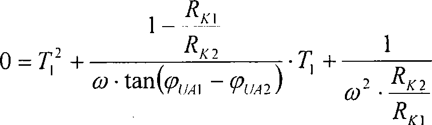
由此,产生如下用于计算想要的时间常数T1的公式:From this, the following formula for calculating the desired time constant T1 results:
在该解中得出的视在解
可以通过比较测量来确定容性分压器20连同同轴电缆40的幅值分压比V。为此,相线30上当前的电压幅值UE由在测量设备10中至少临时存在的并且在图1中由于清楚性原因没有示出的附加的电压测量装置的显示设备读出并且作为在图中没有示出的分析装置100的附加的测量值输入端上的参考值,例如被手动地输入到该分析装置100。该输入可以一次性地进行并且例如在首次安装测量设备时进行。The amplitude divider ratio V of the
为了对在图1中对于开关状态Z1用附图标记UA1表示的并且对于开关状态Z2用附图标记UA2表示的电压测量值进行校正,在分析装置100中例如采用数字滤波器110,如在图4中示例性示出的。数字滤波器110的功能在于,校正通过容性分压器20、同轴电缆40、校准装置50以及内阻RK1确定的测量设备10的传输函数G,并且利用低压测量值UA1和UA2在A/D转换器90的输出端形成校正后的测量值i(k)。为此,在分析装置100中使用相对于待校正的传输函数G的反校正传输函数Gkorr。In order to correct the measured voltage values denoted by the reference symbol U A1 for the switching state Z1 in FIG. It is shown as an example in FIG. 4 . The function of the
因为反校正传输函数Gkorr用对于频率f=0具有无限放大的π单元表示,合适的是,将反校正传输函数设置为具有附加的极点(Polstelle);以这种方式可以避免偏移问题(Offsetprobleme)。作为结果的校正传输函数例如形成具有另一个可自由选择的特征时间常数的一阶高通滤波器。如下合适地设置该时间常数,使得其与测量装置70的电流输入端M70的特征时间常数一致。以下公式示出了产生的校正传输函数:Since the inverse correction transfer function G korr is represented by π-units with infinite amplification for frequency f=0, it is appropriate to arrange the inverse correction transfer function with an additional pole (Polstelle); in this way the offset problem ( Offset problem). The resulting corrected transfer function forms, for example, a first-order high-pass filter with another freely selectable characteristic time constant. This time constant is suitably set such that it corresponds to the characteristic time constant of current input M70 of measuring
TK表示自由选择的时间常数,K表示测量设备的变换系数。K对应于相线30上的电压UE和没有补偿的容性分压器的低压端子U20上的电压UA的商,并且由此在数值上理想地等于幅值分压比V=CO/(CO+CU)。如果测量设备的另一个元件导致放大误差,则同样用因数K校正该放大误差;在这种情况下K和V不再相同。T K stands for a freely selectable time constant and K stands for the conversion factor of the measuring device. K corresponds to the quotient of the voltage U E on the
在使用双线性变换的条件下校正传输函数可以按照以下方式在z区域中被确定:The corrected transfer function can be determined in the z-region using the bilinear transformation as follows:
数字滤波器110由此在z区域中具有以下传输函数:The
为了计算校正传输函数的相关系数得出如下公式:In order to calculate the correlation coefficient of the corrected transfer function, the following formula is obtained:
fa在此表示所使用的采样频率。f a here denotes the sampling frequency used.
在图5中示出了测量设备10的第二实施例,其中作为附加的电气组件60采用电压源200。图6示出形成的等效电路图。FIG. 5 shows a second exemplary embodiment of a measuring
可以利用以下的公式计算输入电压UE:The input voltage U E can be calculated using the following formula:
假定已知电阻R并且电压UK在两个开关状态Z1和Z2中分别取两个不同的已知电压值UK1和UK2,则对于两种开关状态Z1和Z2可以列出以下公式:Assuming that the resistance R is known and that the voltage U K takes two different known voltage values U K1 and U K2 in the two switching states Z1 and Z2 respectively, the following formulas can be listed for the two switching states Z1 and Z2:
在此假定,输入电压UE对于两种开关状态是常量。利用结合图1至4在上面已经讨论的相同的方法求解示出的公式,从而在分析装置100中确定反校正传输函数Gkorr并且可以进一步使用。It is assumed here that the input voltage U E is constant for both switching states. The equations shown are solved using the same method as already discussed above in connection with FIGS. 1 to 4 , so that the inverse correction transfer function G korr is determined in the
Claims (29)


Applications Claiming Priority (1)
| Application Number | Priority Date | Filing Date | Title |
|---|---|---|---|
| PCT/DE2006/001922 WO2008052495A1 (en) | 2006-10-30 | 2006-10-30 | Method and arrangement for measuring the voltage on a conductor |
Publications (2)
| Publication Number | Publication Date |
|---|---|
| CN101535818A true CN101535818A (en) | 2009-09-16 |
| CN101535818B CN101535818B (en) | 2012-04-18 |
Family
ID=38281955
Family Applications (1)
| Application Number | Title | Priority Date | Filing Date |
|---|---|---|---|
| CN2006800562587A Expired - Fee Related CN101535818B (en) | 2006-10-30 | 2006-10-30 | Method and device for measuring voltage on a conductor |
Country Status (3)
| Country | Link |
|---|---|
| CN (1) | CN101535818B (en) |
| DE (1) | DE112006004041A5 (en) |
| WO (1) | WO2008052495A1 (en) |
Cited By (7)
| Publication number | Priority date | Publication date | Assignee | Title |
|---|---|---|---|---|
| CN102288802A (en) * | 2010-05-12 | 2011-12-21 | 吉歌网络有限公司 | Method and circuit for measuring voltage |
| CN105116211A (en) * | 2015-08-27 | 2015-12-02 | 珠海许继电气有限公司 | Suspension type phase voltage measurement device |
| CN107743589A (en) * | 2015-03-20 | 2018-02-27 | Abb瑞士股份有限公司 | Using the high-tension measurement unit of self-correcting |
| CN111133322A (en) * | 2017-09-28 | 2020-05-08 | 西门子股份公司 | Passive components for proving electrical overloading in rotating electrical machines |
| CN111751605A (en) * | 2019-03-29 | 2020-10-09 | 全球能源互联网研究院有限公司 | A high-potential voltage measuring device and method |
| EP4222517A4 (en) * | 2021-09-20 | 2024-11-13 | G & W Electric Company | Compensating for drift in a switch gear voltage sensor |
| TWI903055B (en) * | 2021-03-31 | 2025-11-01 | 美商微晶片科技公司 | Measuring voltage level of a voltage node utilizing a measurement integrated circuit |
Families Citing this family (8)
| Publication number | Priority date | Publication date | Assignee | Title |
|---|---|---|---|---|
| DE102010009235A1 (en) * | 2010-02-25 | 2011-08-25 | Feng, Yongxin, 89079 | Device for measuring interference voltages of high frequencies and low amplitudes in power electronic components of electrical systems, has measurement circuit whose transfer function is determined using parameter estimating algorithm |
| US8493056B2 (en) | 2010-05-12 | 2013-07-23 | Broadcom Corporation | AC voltage measurement circuit |
| DE102010061838A1 (en) * | 2010-11-24 | 2012-05-24 | Siemens Aktiengesellschaft | Measuring and / or voltage conversion device |
| CN102981036B (en) * | 2012-12-18 | 2014-03-26 | 深圳市晶福源电子技术有限公司 | Testing method of multi-output power equipment |
| EP2993480A1 (en) * | 2014-09-04 | 2016-03-09 | 3M Innovative Properties Company | Voltage sensor |
| US10649009B2 (en) | 2018-03-27 | 2020-05-12 | G & W Electric Company | Ungrounded control of low energy analog (LEA) voltage measurements |
| CN115267301B (en) * | 2022-09-30 | 2023-01-20 | 南方电网数字电网研究院有限公司 | Voltage measuring method, voltage measuring device, computer equipment and storage medium |
| EP4614162A1 (en) * | 2024-03-06 | 2025-09-10 | TE Connectivity Solutions GmbH | Capacitive voltage sensor arrangement having a tuning circuit and voltage sensor system |
Family Cites Families (5)
| Publication number | Priority date | Publication date | Assignee | Title |
|---|---|---|---|---|
| US3460032A (en) * | 1967-07-18 | 1969-08-05 | Mallory & Co Inc P R | Capacitor testing apparatus including timer means for controlling the discharge time through different resistances |
| US3870927A (en) * | 1971-06-08 | 1975-03-11 | English Electric Co Ltd | Capacitor voltage transformer system |
| CN1019332B (en) * | 1989-07-22 | 1992-12-02 | 云南省电力工业局试验研究所 | On-line overvoltage monitor for electric power system |
| CN1159586C (en) * | 2002-02-05 | 2004-07-28 | 周友东 | Voltage sensor |
| DE10346356A1 (en) * | 2003-09-26 | 2005-05-12 | Siemens Ag | Method and device for voltage measurement |
-
2006
- 2006-10-30 DE DE112006004041T patent/DE112006004041A5/en not_active Withdrawn
- 2006-10-30 CN CN2006800562587A patent/CN101535818B/en not_active Expired - Fee Related
- 2006-10-30 WO PCT/DE2006/001922 patent/WO2008052495A1/en not_active Ceased
Cited By (14)
| Publication number | Priority date | Publication date | Assignee | Title |
|---|---|---|---|---|
| CN102288802B (en) * | 2010-05-12 | 2014-02-26 | 吉歌网络有限公司 | Method and circuit for measuring voltage |
| CN102288802A (en) * | 2010-05-12 | 2011-12-21 | 吉歌网络有限公司 | Method and circuit for measuring voltage |
| US10901004B2 (en) | 2015-03-20 | 2021-01-26 | Abb Schweiz Ag | High-voltage measuring unit with self-correction |
| CN107743589A (en) * | 2015-03-20 | 2018-02-27 | Abb瑞士股份有限公司 | Using the high-tension measurement unit of self-correcting |
| CN107743589B (en) * | 2015-03-20 | 2020-04-14 | Abb瑞士股份有限公司 | High-voltage measuring cell with self-calibration |
| CN105116211A (en) * | 2015-08-27 | 2015-12-02 | 珠海许继电气有限公司 | Suspension type phase voltage measurement device |
| CN105116211B (en) * | 2015-08-27 | 2018-03-16 | 珠海许继电气有限公司 | A kind of floating type phase voltage measurement apparatus |
| CN111133322A (en) * | 2017-09-28 | 2020-05-08 | 西门子股份公司 | Passive components for proving electrical overloading in rotating electrical machines |
| CN111133322B (en) * | 2017-09-28 | 2022-08-19 | 西门子股份公司 | Passive component for proving an electrical overload in a rotating electrical machine |
| US11967869B2 (en) | 2017-09-28 | 2024-04-23 | Innomotics Gmbh | Passive component for detecting an electrical overload in electrically rotating machines |
| CN111751605A (en) * | 2019-03-29 | 2020-10-09 | 全球能源互联网研究院有限公司 | A high-potential voltage measuring device and method |
| CN111751605B (en) * | 2019-03-29 | 2024-01-16 | 全球能源互联网研究院有限公司 | A high potential voltage measurement device and method |
| TWI903055B (en) * | 2021-03-31 | 2025-11-01 | 美商微晶片科技公司 | Measuring voltage level of a voltage node utilizing a measurement integrated circuit |
| EP4222517A4 (en) * | 2021-09-20 | 2024-11-13 | G & W Electric Company | Compensating for drift in a switch gear voltage sensor |
Also Published As
| Publication number | Publication date |
|---|---|
| WO2008052495A1 (en) | 2008-05-08 |
| CN101535818B (en) | 2012-04-18 |
| HK1131441A1 (en) | 2010-01-22 |
| DE112006004041A5 (en) | 2009-07-02 |
Similar Documents
| Publication | Publication Date | Title |
|---|---|---|
| JP7412386B2 (en) | Method and apparatus for learning phase errors or timing delays in current converters and power measurement apparatus including current converter error correction | |
| CN101535818B (en) | Method and device for measuring voltage on a conductor | |
| CN105572451B (en) | Self-correcting current transformer system | |
| CN100523832C (en) | Method and apparatus for phase compensation in an electronic energy meter | |
| US11705275B2 (en) | Self calibration by double signal sampling | |
| EP2745121B1 (en) | An adaptive voltage divider with corrected frequency characteristic for measuring high voltages | |
| US10209280B2 (en) | Circuit breaker | |
| US9507006B2 (en) | Method for calibrating a current transducer of the rogowski type | |
| CN100507579C (en) | Method and device for measuring voltage | |
| CN100437128C (en) | Energy Consumption Metering Device | |
| RU2250471C1 (en) | Voltage divided for measurements conducting at commutation tests of high-voltage equipment and method of compensation of influence on division ratio of grounded voltage divider capacitance | |
| US6803776B2 (en) | Current-comparator-based four-terminal resistance bridge for power frequencies | |
| KR101154449B1 (en) | Evaluation system and method to obtain ratio error and displacement error of current transformer | |
| So et al. | A direct-reading ac comparator bridge for resistance measurement at power frequencies | |
| CN106199285B (en) | Capacitance characteristic measuring equipment and method under any alternating current carrier | |
| KR101851967B1 (en) | Capacitor-registor bank apparatus for evaluating capacitance bridge | |
| JP2007003407A (en) | Method and apparatus for measuring impedance | |
| KR100996206B1 (en) | Inductor evaluation system using current comparator and evaluation method using same | |
| CN210982711U (en) | Three-phase current detection circuit and electric energy metering chip | |
| Reynolds et al. | DC insulation analysis: A new and better method | |
| WO2001051937A1 (en) | Device and method for calibration of an electricity meter | |
| Aristoy et al. | Effects of stray capacitances on high voltage current transformers | |
| US20040061489A1 (en) | Switchable impedance circuit for current sensing an electricity meter | |
| HK1131441B (en) | Method and arrangement for measuring the voltage on a conductor | |
| Marais et al. | Reduction of static electricity meter errors by broadband compensation of voltage and current channel differences |
Legal Events
| Date | Code | Title | Description |
|---|---|---|---|
| C06 | Publication | ||
| PB01 | Publication | ||
| C10 | Entry into substantive examination | ||
| SE01 | Entry into force of request for substantive examination | ||
| REG | Reference to a national code |
Ref country code: HK Ref legal event code: DE Ref document number: 1131441 Country of ref document: HK |
|
| C14 | Grant of patent or utility model | ||
| GR01 | Patent grant | ||
| REG | Reference to a national code |
Ref country code: HK Ref legal event code: GR Ref document number: 1131441 Country of ref document: HK |
|
| CF01 | Termination of patent right due to non-payment of annual fee |
Granted publication date: 20120418 Termination date: 20151030 |
|
| EXPY | Termination of patent right or utility model |