CN101529777A - Method for transmitting data using cyclic delay diversity - Google Patents
Method for transmitting data using cyclic delay diversity Download PDFInfo
- Publication number
- CN101529777A CN101529777A CNA2007800393850A CN200780039385A CN101529777A CN 101529777 A CN101529777 A CN 101529777A CN A2007800393850 A CNA2007800393850 A CN A2007800393850A CN 200780039385 A CN200780039385 A CN 200780039385A CN 101529777 A CN101529777 A CN 101529777A
- Authority
- CN
- China
- Prior art keywords
- antenna
- matrix
- cyclic delay
- phase
- diversity
- Prior art date
- Legal status (The legal status is an assumption and is not a legal conclusion. Google has not performed a legal analysis and makes no representation as to the accuracy of the status listed.)
- Pending
Links
Images


Classifications
-
- H—ELECTRICITY
- H04—ELECTRIC COMMUNICATION TECHNIQUE
- H04B—TRANSMISSION
- H04B7/00—Radio transmission systems, i.e. using radiation field
- H04B7/02—Diversity systems; Multi-antenna system, i.e. transmission or reception using multiple antennas
- H04B7/04—Diversity systems; Multi-antenna system, i.e. transmission or reception using multiple antennas using two or more spaced independent antennas
- H04B7/06—Diversity systems; Multi-antenna system, i.e. transmission or reception using multiple antennas using two or more spaced independent antennas at the transmitting station
- H04B7/0613—Diversity systems; Multi-antenna system, i.e. transmission or reception using multiple antennas using two or more spaced independent antennas at the transmitting station using simultaneous transmission
- H04B7/0667—Diversity systems; Multi-antenna system, i.e. transmission or reception using multiple antennas using two or more spaced independent antennas at the transmitting station using simultaneous transmission of delayed versions of same signal
- H04B7/0671—Diversity systems; Multi-antenna system, i.e. transmission or reception using multiple antennas using two or more spaced independent antennas at the transmitting station using simultaneous transmission of delayed versions of same signal using different delays between antennas
-
- H—ELECTRICITY
- H04—ELECTRIC COMMUNICATION TECHNIQUE
- H04L—TRANSMISSION OF DIGITAL INFORMATION, e.g. TELEGRAPHIC COMMUNICATION
- H04L27/00—Modulated-carrier systems
- H04L27/26—Systems using multi-frequency codes
- H04L27/2601—Multicarrier modulation systems
- H04L27/2602—Signal structure
Landscapes
- Engineering & Computer Science (AREA)
- Computer Networks & Wireless Communication (AREA)
- Signal Processing (AREA)
- Radio Transmission System (AREA)
Abstract
Description
技术领域 technical field
本发明涉及一种在MIMO(多输入多输出)-OFDM(正交频分复用)系统中发射信号的方法。The present invention relates to a method of transmitting signals in a MIMO (Multiple Input Multiple Output)-OFDM (Orthogonal Frequency Division Multiplexing) system.
背景技术 Background technique
近来,由于信息通信服务的普及、各种多媒体服务的到来、以及高质量服务的出现,对无线通信服务的要求迅速地增加。为了主动应对该要求,首先应提高通信系统的容量。为了提高无线通信环境中的通信容量,能够考虑找到新的可用频带的方法或者提高有限资源的效率的方法。对于后者的方法,以向发射机和接收机提供多个天线的方式额外确保关于资源利用的空间域以获得分集增益,或者以通过每个天线并行地发射数据的方式,提高容量的发射规模。该技术被称为多天线发射/接收技术,对于该技术的研究和开发已积极付出许多努力。Recently, due to the spread of information communication services, the advent of various multimedia services, and the emergence of high-quality services, the demand for wireless communication services has rapidly increased. In order to proactively respond to this requirement, the capacity of the communication system should first be increased. In order to increase communication capacity in a wireless communication environment, a method of finding a new usable frequency band or a method of improving efficiency of limited resources can be considered. For the latter approach, either by providing multiple antennas to the transmitter and receiver to additionally ensure the spatial domain on resource utilization for diversity gain, or by transmitting data through each antenna in parallel, increasing the transmission scale for capacity . This technique is called a multi-antenna transmission/reception technique, and many efforts have been actively made for the research and development of this technique.
在多天线发射/接收技术中,将参考图1对使用OFDM(正交频分复用)的多输入多输出(MIMO)系统的通用结构解释如下。Among multi-antenna transmission/reception techniques, a general structure of a multiple-input multiple-output (MIMO) system using OFDM (Orthogonal Frequency Division Multiplexing) will be explained with reference to FIG. 1 as follows.
在发射端中,信道编码器101以使冗余比特附加到发射数据比特的方式减少由信道或噪声引起的影响。映射器103将数据比特信息变换为数据符号信息。串行-并行转换器105使数据符号并行化以在多个子载波上传送。多天线编码器107将并行化数据符号变换为空间时间信号。In the transmitting end, the
在接收端中,多天线解码器109、并行-串行转换器111、解映射器113和信道解码器115分别执行与发射端中的多天线编码器107、串行-并行转换器105、映射器103和信道编码器101相反的功能。In the receiving end, the
对于MIMO-OFDM系统,需要各种技术以提高数据发射的可靠性。作为用于增加空间分集增益的方案,存在空间-时间码(STC)、循环延迟分集(CDD)等。作为用于增加信噪比(SNR)的方案,存在波束形成(BF)、预编码等。在该情况中,通常使用空间-时间码或者循环延迟分集方案提供开环系统的鲁棒性,在该开环系统中由于信道的快速时间更新,在发射端处反馈信息是不可用的。另一方面,通常在闭环系统中使用波束形成或者预编码,以便于通过使用包括空间信道属性的反馈信息使信噪比最大。For MIMO-OFDM systems, various techniques are required to improve the reliability of data transmission. As a scheme for increasing space diversity gain, there are Space-Time Code (STC), Cyclic Delay Diversity (CDD), and the like. As a scheme for increasing a signal-to-noise ratio (SNR), there are beamforming (BF), precoding, and the like. In this case, space-time codes or cyclic delay diversity schemes are usually used to provide the robustness of open-loop systems where feedback information is not available at the transmitting end due to the fast time updates of the channel. On the other hand, beamforming or precoding is usually used in a closed-loop system in order to maximize the signal-to-noise ratio by using feedback information including spatial channel properties.
作为上文提及的方案中的用于增加空间分集增益的方案和用于增加信噪比的方案,将循环延迟分集和预编码详细解释如下。As a scheme for increasing space diversity gain and a scheme for increasing signal-to-noise ratio among the above-mentioned schemes, cyclic delay diversity and precoding are explained in detail as follows.
首先,在循环延迟方案中,接收端以如下方式获得频率分集增益,即,在配有多个发射天线的系统中,每个天线在发射OFDM信号时发射延迟或尺寸不同的信号。图2示出了使用循环分集方案的多天线发射机的配置。First, in the cyclic delay scheme, the receiver obtains frequency diversity gain in such a way that, in a system equipped with multiple transmit antennas, each antenna transmits signals with different delays or sizes when transmitting OFDM signals. Figure 2 shows the configuration of a multi-antenna transmitter using a cyclic diversity scheme.
OFDM符号是通过每个天线被发射的,并且不同的循环延迟值被应用到发射天线。将循环前缀(CP)附加到其上以防止信道间干扰。对应的信号随后被发射到接收端。这样做时,自第一天线递送的数据序列被完整无缺地发射到接收端。然而,自其他天线递送的数据序列以如下方式被发射,即相比于前一天线,被循环延迟预先确定的比特。OFDM symbols are transmitted through each antenna, and different cyclic delay values are applied to the transmit antennas. A cyclic prefix (CP) is appended to it to prevent inter-channel interference. The corresponding signal is then transmitted to the receiving end. In doing so, the data sequence delivered from the first antenna is transmitted intact to the receiving end. However, data sequences delivered from other antennas are transmitted in such a way that they are cyclically delayed by a predetermined bit compared to the previous antenna.
同时,如果在频域上实现循环延迟分集方案,循环延迟可被表示为相位序列的乘法。特别地,参考图3,将频域上的每个数据序列与针对每个天线被不同设置的规定相位序列(相位序列1~相位序列M)相乘,对其执行快速傅立叶逆变换(IFFT),并且随后将对应的结果发射到接收端。这被称为相移分集方案。Meanwhile, if the cyclic delay diversity scheme is implemented on the frequency domain, the cyclic delay can be expressed as the multiplication of the phase sequence. In particular, referring to FIG. 3 , each data sequence in the frequency domain is multiplied by a prescribed phase sequence (
相移分集方案可以通过增加接收端处的信道延迟扩展,人为地将频率选择性引入平坦衰落信道。由此,可以获得频率分集增益或者频率调度增益。Phase-shift diversity schemes can artificially introduce frequency selectivity into flat-fading channels by increasing the channel delay spread at the receiver. Thus, frequency diversity gain or frequency scheduling gain can be obtained.
预编码方案包括用于其中闭环系统中的反馈信息为有限的情况的基于码本(codebook)的预编码方案,或者用于量化反馈信道信息的方案。基于码本的预编码是用于以如下方式获得信噪比(SNR)增益的方案,即向发射端反馈发射端和接收端已知的预编码矩阵索引。The precoding scheme includes a codebook-based precoding scheme for a case where feedback information in a closed-loop system is limited, or a scheme for quantizing feedback channel information. Codebook-based precoding is a scheme for obtaining a signal-to-noise ratio (SNR) gain by feeding back a precoding matrix index known at a transmitting end and a receiving end to the transmitting end.
图4是根据现有技术的使用基于码本的预编码的多天线系统的发射端和接收端的框图。4 is a block diagram of a transmitting end and a receiving end of a multi-antenna system using codebook-based precoding according to the prior art.
参考图4,每个发射端和接收端具有预先定义的有限预编码矩阵(P1~PL)。接收端使用信道信息向发射端反馈优选的或者最优的预编码矩阵索引(1)。发射端向发射数据(x1~XMt)应用对应于该反馈索引的预编码矩阵。作为参考,表1示例性地示出了可应用于如下情况的码本,该情况即支持具有两个发射天线的空间复用率为2的IEEE802.16e系统使用3比特反馈信息。Referring to FIG. 4 , each transmitting end and receiving end has a predefined finite precoding matrix (P 1 ˜PL ). The receiving end uses the channel information to feed back the preferred or optimal precoding matrix index (1) to the transmitting end. The transmitting end applies the precoding matrix corresponding to the feedback index to the transmission data (x 1 ˜X Mt ). For reference, Table 1 exemplarily shows a codebook applicable to a case where an IEEE802.16e system supporting a spatial multiplexing rate of 2 with two transmit antennas uses 3-bit feedback information.
[表1][Table 1]

发明内容 Contents of the invention
技术问题technical problem
在获得开环中的频率选择性分集增益和闭环中的频率调度增益时,上文解释的相移分集方案也是有利的。因此,迄今为止已研究和调查了相移分集方案。然而,常规相移分集方案将空间复用率限制为1,因此也限制了最大数据速率。在资源分配被固定执行的情况中,难于获得上文的增益。The phase shift diversity scheme explained above is also advantageous in obtaining frequency selective diversity gain in open loop and frequency scheduling gain in closed loop. Therefore, phase shift diversity schemes have been studied and investigated so far. However, conventional phase-shift diversity schemes limit the spatial multiplexing ratio to 1, thus limiting the maximum data rate. In the case where resource allocation is fixedly performed, it is difficult to obtain the above gain.
由于上文解释的基于码本的预编码方案能够通过需要小尺寸的反馈信息(索引信息)使用高的空间复用率,因此其在实现有效的数据发射时是有利的。Since the codebook-based precoding scheme explained above can use a high spatial multiplexing rate by requiring small-sized feedback information (index information), it is advantageous in realizing efficient data transmission.
然而,应确保稳定的信道用于反馈。因此,其不适用于具有相当大的信道变化的移动环境。并且,其仅可应用于闭环系统。However, a stable channel should be ensured for feedback. Therefore, it is not suitable for mobile environments with considerable channel variations. Also, it is only applicable to closed-loop systems.
技术方案Technical solutions
因此,本发明涉及一种在使用多个子载波的多天线系统中使用循环延迟发射数据的方法,该方法基本上消除了由于现有技术的限制和缺陷引起的一个或多个问题。Accordingly, the present invention is directed to a method of transmitting data using a cyclic delay in a multi-antenna system using multiple subcarriers that substantially obviates one or more problems due to limitations and disadvantages of the related art.
本发明的目的在于提供一种通用化的基于相移的预编码方案,该方案的使用与天线配置和空间复用率无关,同时保持了现有技术的循环延迟分集、相移分集和预编码方案的优点。The purpose of the present invention is to provide a generalized phase-shift-based precoding scheme, which has nothing to do with antenna configuration and spatial multiplexing ratio, while maintaining the cyclic delay diversity, phase-shift diversity and precoding of the prior art Advantages of the program.
本发明的另一目的在于,以如下方式提供一种增强型基于相移的预编码方案或者增强型循环延迟分集方案,即向前文所述的基于相移的预编码方案选择性地添加时变相移分集、时变循环延迟分集等。Another object of the present invention is to provide an enhanced phase-shift-based precoding scheme or an enhanced cyclic delay diversity scheme in such a manner that a time-varying phase is selectively added to the aforementioned phase-shift-based precoding scheme. shift diversity, time-varying cyclic delay diversity, etc.
本发明的额外特征和优点将在下文的描述中被阐述,并且部分地将通过该描述而是显而易见的,或者可以通过实践本发明而被习得。通过书面描述及其权利要求以及附图中特别指出的结构,将实现和达到本发明的目的和其他优点。Additional features and advantages of the invention will be set forth in the description which follows, and in part will be obvious from the description, or may be learned by practice of the invention. The objectives and other advantages of the invention will be realized and attained by the structure particularly pointed out in the written description and claims hereof as well as the appended drawings.
为了实现这些和其他优点并且根据本发明的目的,如具体化和广泛描述的,根据本发明的一种在MIMO(多输入多输出)-OFDM(正交频分复用)系统中发射信号的方法包括如下步骤:通过考虑时变元素,空间处理对应于频域上的每个子载波的OFDM符号;将空间处理的OFDM符号变换为时域上的发射信号;以及将空间处理的OFDM符号变换为时域上的发射信号。To achieve these and other advantages and in accordance with the purpose of the present invention, as embodied and broadly described, a method for transmitting signals in a MIMO (Multiple Input Multiple Output)-OFDM (Orthogonal Frequency Division Multiplexing) system according to the present invention The method comprises the steps of: spatially processing OFDM symbols corresponding to each subcarrier in the frequency domain by taking into account time-varying elements; transforming the spatially processed OFDM symbols into transmitted signals in the time domain; and transforming the spatially processed OFDM symbols into Transmitted signal in time domain.
优选地,在本发明的实施例中,该方法可以进一步包括至少一个如下步骤:向空间处理的OFDM信号添加对应于每个天线的第一导频符号,使发射信号与多个每天线权重相乘,以及向发射信号应用规定的循环延迟。Preferably, in an embodiment of the present invention, the method may further include at least one of the following steps: adding a first pilot symbol corresponding to each antenna to the spatially processed OFDM signal, making the transmitted signal equal to a plurality of antenna weights multiply, and apply the specified cyclic delay to the transmit signal.
为了进一步实现这些和其他优点并且根据本发明的目的,根据本发明的一种在MIMO(多输入多输出)-OFDM(正交频分复用)系统中发射信号的方法包括如下步骤:对分别对应于频域上的多个子载波的OFDM符号执行预编码,将预编码的OFDM符号变换为时域上的每天线信号,将规定的循环延迟应用到每个每天线信号,以及发射每天线信号。In order to further realize these and other advantages and according to the purpose of the present invention, a method for transmitting signals in a MIMO (Multiple Input Multiple Output)-OFDM (Orthogonal Frequency Division Multiplexing) system according to the present invention comprises the following steps: Precoding is performed on OFDM symbols corresponding to a plurality of subcarriers in the frequency domain, transforming the precoded OFDM symbols into per-antenna signals in the time domain, applying a prescribed cyclic delay to each per-antenna signal, and transmitting per-antenna signal .
优选地,在本发明的实施例中,该方法可以进一步包括至少一个如下步骤:向每个预编码的OFDM符号添加对应于每个天线的第一导频符号,以及向每个循环延迟的每天线信号添加变换到时域的第二导频符号。Preferably, in the embodiment of the present invention, the method may further include at least one of the following steps: adding the first pilot symbol corresponding to each antenna to each precoded OFDM symbol, and adding the daily The line signal is added with a second pilot symbol transformed into the time domain.
为了进一步实现这些和其他优点并且根据本发明的目的,根据本发明的一种在MIMO(多输入多输出)-OFDM(正交频分复用)系统中发射信号的方法包括如下步骤:通过使关于相移的第一矩阵与用于将第一矩阵变换为酉矩阵的第二矩阵相乘,来确定基于相移的预编码矩阵;通过使OFDM符号与对应于多个子载波中的每个子载波的确定的基于相移的预编码矩阵相乘,进行基于相移的预编码;将基于相移的预编码的OFDM符号变换为时域上的发射信号;向每个发射信号应用规定的循环延迟;以及发射循环延迟的发射信号。In order to further realize these and other advantages and according to the purpose of the present invention, a method of transmitting signals in a MIMO (Multiple Input Multiple Output)-OFDM (Orthogonal Frequency Division Multiplexing) system according to the present invention comprises the following steps: by using The phase shift based precoding matrix is determined by multiplying the first matrix for phase shift with the second matrix for transforming the first matrix into a unitary matrix; Multiply the determined phase-shift-based precoding matrix to perform phase-shift-based precoding; transform the phase-shift-based precoded OFDM symbols into transmitted signals in the time domain; apply a specified cyclic delay to each transmitted signal ; and transmit signal with transmit cycle delay.
优选地,在本发明的实施例中,该方法可以进一步包括至少一个如下步骤:使每个发射信号与多个每天线权重相乘,向每个基于相移的预编码的OFDM信号添加对应于每个天线的第一导频符号,以及向每个循环延迟的发射信号添加变换到时域的第二导频符号。Preferably, in the embodiment of the present invention, the method may further include at least one of the following steps: multiply each transmitted signal by a plurality of antenna weights, and add the corresponding A first pilot symbol for each antenna, and a second pilot symbol transformed to the time domain is added to each cyclically delayed transmit signal.
并且,基于相移的预编码矩阵可以表示为And, the phase-shift based precoding matrix can be expressed as

并且,其中第一矩阵或第二矩阵的相位角度θi(t)(i=1,...,Nt)是时变元素。And, wherein the phase angle θ i (t) (i=1, . . . , N t ) of the first matrix or the second matrix is a time-varying element.
为了进一步实现这些和其他优点并且根据本发明的目的,根据本发明的一种发射信号的方法包括如下步骤:对待经由多个天线中的至少一个天线发射的每个数据流执行与多个天线关联的空间处理;对空间处理的数据流执行发射功率分配预编码,以控制用于多个天线的发射功率;将发射功率分配预编码的数据流变换为时域上的每天线信号;以及经由多个天线中的至少一个天线发射每天线信号。To further achieve these and other advantages and in accordance with the object of the present invention, a method of transmitting signals according to the present invention comprises the steps of performing an association with a plurality of antennas for each data stream to be transmitted via at least one of the plurality of antennas spatial processing; perform transmit power allocation precoding on the spatially processed data streams to control transmit power for multiple antennas; transform the transmit power allocation precoded data streams into per-antenna signals in the time domain; and via multiple At least one of the antennas transmits each antenna signal.
优选地,在本发明的实施例中,该方法可以进一步包括至少一个如下步骤:对每个空间处理的数据流应用相移分集,以及对每天线信号应用循环延迟分集。Preferably, in the embodiment of the present invention, the method may further include at least one of the following steps: applying phase shift diversity to each spatially processed data stream, and applying cyclic delay diversity to each antenna signal.
并且,相移分集可以应用大的循环延迟值,且其中循环延迟分集可以应用小的循环延迟值。Also, the phase shift diversity can apply a large cyclic delay value, and wherein the cyclic delay diversity can apply a small cyclic delay value.
并且,该方法可以进一步包括至少一个如下步骤:向空间处理的数据流添加第一导频符号,向发射功率分配预编码的数据流添加第二导频符号,以及向每天线信号应用变换到时域的第三导频符号。And, the method may further comprise at least one of the steps of: adding a first pilot symbol to the spatially processed data stream, adding a second pilot symbol to the transmit power allocation precoded data stream, and applying a transformation to each antenna signal domain's third pilot symbol.
并且,发射功率分配预编码可以通过与Nt×Nt酉矩阵(Nt是多个天线的数目)相乘而被执行。并且,Nt×Nt酉矩阵可以与具有相位值作为变量的对角矩阵相乘。并且,Nt×Nt酉矩阵和对角矩阵至少之一可以是时变元素。And, transmit power allocation precoding may be performed by multiplying with an N t ×N t unitary matrix (N t is the number of multiple antennas). And, the N t ×N t unitary matrix may be multiplied with a diagonal matrix having a phase value as a variable. And, at least one of the N t ×N t unitary matrix and the diagonal matrix may be a time-varying element.
应当理解,前面的一般描述和后面的详细描述是示例性的和说明性的,并且用于提供所要求保护的本发明的进一步的解释。It is to be understood that both the foregoing general description and the following detailed description are exemplary and explanatory and are intended to provide further explanation of the invention as claimed.
技术效果technical effect
因此,本发明提供了如下效果或优点。Therefore, the present invention provides the following effects or advantages.
首先,本发明的基于相移的预编码方案能够自适应地应对信道状态或系统状态,与天线配置或空间复用率无关,同时保持由现有技术的相移分集或预编码方案提供的优点。First, the phase-shift-based precoding scheme of the present invention is able to adaptively cope with channel state or system state, independent of antenna configuration or spatial multiplexing ratio, while maintaining the advantages provided by prior art phase-shift diversity or precoding schemes .
其次,通过针对基于相移的预编码方案选择性地采用时间相关的相位变化和循环延迟方案等,增强了发射机/接收机的复杂度并且与每个多天线方案的组合是可用的。Second, by selectively employing time-dependent phase variation and cyclic delay schemes etc. for phase-shift based precoding schemes, the complexity of the transmitter/receiver is enhanced and combinations with each multi-antenna scheme are available.
第三,本发明可以通过改变每个用户的通信条件而应用,由此获得了最优的通信性能。Third, the present invention can be applied by changing the communication conditions of each user, whereby optimal communication performance is obtained.
附图说明 Description of drawings
所包括的附图用于提供对本发明的进一步的理解并且被并入本说明书并且构成本说明书的一部分,附图说明了本发明的实施例并且连同描述一起用于解释本发明的原理。The accompanying drawings, which are included to provide a further understanding of the invention and are incorporated in and constitute a part of this specification, illustrate embodiments of the invention and together with the description serve to explain the principle of the invention.
在附图中:In the attached picture:
图1是具有多个发射和接收天线的正交频分复用系统的框图;Figure 1 is a block diagram of an OFDM system with multiple transmit and receive antennas;
图2是使用循环延迟分集方案的多天线系统的发射端的框图;2 is a block diagram of a transmitting end of a multi-antenna system using a cyclic delay diversity scheme;
图3是使用相移分集方案的多天线系统的发射端的框图;3 is a block diagram of a transmitting end of a multi-antenna system using a phase-shift diversity scheme;
图4是使用预编码方案的多天线系统的发射端和接收端的框图;4 is a block diagram of a transmitting end and a receiving end of a multi-antenna system using a precoding scheme;
图5是用于执行基于相移的预编码的发射机和接收机的框图;5 is a block diagram of a transmitter and receiver for performing phase-shift based precoding;
图6是关于如下情况的框图,即空间复用方案和循环延迟分集方案被应用于具有四个发射天线的空间复用率为2的多天线系统;6 is a block diagram for a case where a spatial multiplexing scheme and a cyclic delay diversity scheme are applied to a multi-antenna system having a spatial multiplexing rate of 2 with four transmit antennas;
图7是关于如下情况的框图,即基于相移的预编码矩阵被应用到图6中示出的多天线系统;FIG. 7 is a block diagram for a case where a phase-shift based precoding matrix is applied to the multi-antenna system shown in FIG. 6;
图8是关于基于相移的预编码矩阵的重新配置方法的示图;Fig. 8 is a diagram about a reconfiguration method of a precoding matrix based on a phase shift;
图9是关于基于相移的预编码和相移分集的两种应用的曲线的示图;Figure 9 is a diagram of curves for two applications of phase-shift based precoding and phase-shift diversity;
图10是根据本发明的实施例的支持GCDD方案的发射机和接收机的概念示图;10 is a conceptual diagram of a transmitter and a receiver supporting a GCDD scheme according to an embodiment of the present invention;
图11是根据本发明的实施例的支持GCDD方案的修改的发射机和接收机的概念示图;11 is a conceptual diagram of a modified transmitter and receiver supporting the GCDD scheme according to an embodiment of the present invention;
图12是根据本发明的实施例的被应用了GPSD方案和GCDD方案的组合的发射机和接收机的概念示图;12 is a conceptual diagram of a transmitter and a receiver to which a combination of the GPSD scheme and the GCDD scheme is applied according to an embodiment of the present invention;
图13是根据本发明的实施例的关于GPSD方案和GCDD方案的组合被修改的情况的发射机和接收机的概念示图;13 is a conceptual diagram of a transmitter and a receiver for a case where a combination of a GPSD scheme and a GCDD scheme is modified according to an embodiment of the present invention;
图14是根据本发明的实施例的关于在IFFT之前将导频符号应用到执行的GPSD方案的情况的示图;FIG. 14 is a diagram about a situation in which pilot symbols are applied to a GPSD scheme performed before IFFT according to an embodiment of the present invention;
图15是根据本发明的实施例的用于将图12中示出的GPSD方案应用部分表示为式的示图;15 is a diagram for expressing the GPSD scheme application part shown in FIG. 12 as an equation according to an embodiment of the present invention;
图16是根据本发明的实施例的关于在循环延迟分集之后应用导频符号的情况的示图;FIG. 16 is a diagram about a case where pilot symbols are applied after cyclic delay diversity according to an embodiment of the present invention;
图17是根据本发明的实施例的用于将图16中示出的GPSD方案应用部分表示为式的示图;17 is a diagram for expressing the GPSD scheme application part shown in FIG. 16 as an equation according to an embodiment of the present invention;
图18是根据本发明的实施例的关于同时应用图14和图16中示出的导频符号应用方法的情况的示图;18 is a diagram about a case where the pilot symbol application methods shown in FIGS. 14 and 16 are simultaneously applied according to an embodiment of the present invention;
图19是关于在ITU pedestrian-A信道上的GCDD系统和现有技术系统的仿真测试结果的曲线图;Fig. 19 is a graph about the simulation test results of the GCDD system and the prior art system on the ITU pedestrian-A channel;
图20是Typical Urban(6-ray)环境中的仿真测试结果的曲线图;Fig. 20 is the graph of the simulation test result in Typical Urban (6-ray) environment;
图21是根据本发明的实施例的用于应用发射功率分配预编码矩阵的发射机和接收机的示例性框图;21 is an exemplary block diagram of a transmitter and a receiver for applying a transmit power allocation precoding matrix according to an embodiment of the present invention;
图22是根据本发明的实施例的用于应用发射功率分配预编码矩阵的发射机和接收机的示例性框图;22 is an exemplary block diagram of a transmitter and a receiver for applying a transmit power allocation precoding matrix according to an embodiment of the present invention;
图23是根据本发明的实施例的用于应用发射功率分配预编码矩阵的发射机和接收机的示例性框图;23 is an exemplary block diagram of a transmitter and a receiver for applying a transmit power allocation precoding matrix according to an embodiment of the present invention;
图24是根据本发明的实施例的用于将导频符号应用于图21或图23中示出的实施例的发射机和接收机的示例性框图;FIG. 24 is an exemplary block diagram of a transmitter and a receiver for applying pilot symbols to the embodiment shown in FIG. 21 or FIG. 23 according to an embodiment of the present invention;
图25是根据本发明的实施例的用于将导频符号应用于图22中示出的实施例的发射机和接收机的示例性框图;FIG. 25 is an exemplary block diagram of a transmitter and a receiver for applying pilot symbols to the embodiment shown in FIG. 22 according to an embodiment of the present invention;
图26是根据本发明的实施例的用于将导频符号应用于图21或图23中示出的实施例的发射机和接收机的示例性框图;FIG. 26 is an exemplary block diagram of a transmitter and a receiver for applying pilot symbols to the embodiment shown in FIG. 21 or FIG. 23 according to an embodiment of the present invention;
图27是根据本发明的实施例的用于将导频符号应用于图23中示出的实施例的发射机和接收机的示例性框图;并且FIG. 27 is an exemplary block diagram of a transmitter and a receiver for applying pilot symbols to the embodiment shown in FIG. 23 according to an embodiment of the present invention; and
图28是根据本发明的实施例的用于将导频符号应用于图21或图23中示出的实施例的发射机和接收机的示例性框图。FIG. 28 is an exemplary block diagram of a transmitter and a receiver for applying pilot symbols to the embodiment shown in FIG. 21 or FIG. 23 according to an embodiment of the present invention.
具体实施方式 Detailed ways
现将详细参考本发明的优选实施例,在附图中说明了该优选实施例的示例。Reference will now be made in detail to the preferred embodiments of the present invention, examples of which are illustrated in the accompanying drawings.
第一实施例:基于相移的预编码First Embodiment: Precoding Based on Phase Shift
生成基于相移的预编码矩阵Generate phase-shift based precoding matrix
基于相移的预编码矩阵(P)可以如下表示The phase shift based precoding matrix (P) can be expressed as follows
[式1][Formula 1]

在式1中,wi,j k(i=1,...,Nt,j=1,...,R)指出了由子载波索引或特定频带索引k确定的复权重,Nt指出了发射天线的数目,并且R指出了空间复用率。在该情况中,发射天线可以包括物理发射天线或虚拟发射天线。如果发射天线包括虚拟天线,则Nt等于R。In
该复权重可以具有根据与天线相乘的OFDM符号以及索引或对应的子载波变化的值。并且,可以根据信道状态和反馈信息存在与否的至少之一确定该复权重。The complex weight may have a value varying according to an OFDM symbol multiplied by an antenna and an index or a corresponding subcarrier. Also, the complex weight may be determined according to at least one of channel state and presence or absence of feedback information.
同时,式1中示出的基于相移的预编码矩阵(P)优选地被设计为酉矩阵以减少多天线系统中的信道容量损失。在该情况中,多天线开环系统的信道容量被表示为下式以观察关于酉矩阵配置的条件。Meanwhile, the phase-shift-based precoding matrix (P) shown in
[式2][Formula 2]
在式2中,H指出了Nr×Nt多天线信道矩阵,Nt指出了发射天线的数目,并且Nr指出了接收天线的数目。式3中示出了将基于相移的预编码矩阵P应用于式2的结果。In
[式3][Formula 3]

在式3中,由于PPH应是用于防止信道容量损失的单位矩阵,因此基于相移的预编码矩阵P应对应于满足如下条件的酉矩阵。In
[式4][Formula 4]
PPH=IN PP H = I N
为了使基于相移的预编码矩阵P变为酉矩阵,如下两类条件,即功率限制条件和正交性限制条件。功率限制用于使构造矩阵的每个列的列元素的平方和是1。并且,正交性限制用于提供列之间的正交特性。该条件被表示为下式。In order to make the precoding matrix P based on the phase shift into a unitary matrix, the following two types of conditions are required, ie, the power limitation condition and the orthogonality limitation condition. The power limit is used to make the sum of the squares of the column elements of each column of the construction matrix be one. Also, orthogonality constraints are used to provide orthogonality between columns. This condition is represented by the following formula.
[式5][Formula 5]
[式6][Formula 6]
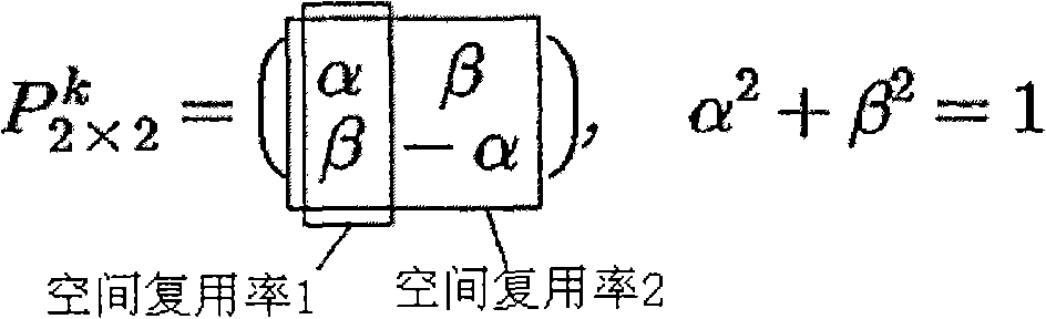
根据本发明的一个实施例,提出了2×2的基于相移的预编码矩阵的通式。并且,如下考虑满足上文的两类条件的式。式7示出了具有两个发射天线的空间复用率为2的基于相移的预编码矩阵的通式。According to an embodiment of the present invention, a general formula of a 2×2 phase shift-based precoding matrix is proposed. And, the formula satisfying the above two types of conditions is considered as follows. Equation 7 shows a general expression of a phase-shift based precoding matrix with a spatial multiplexing rate of 2 with two transmit antennas.
[式7][Formula 7]
在式7中,αi或βi(i=1,2)是实数,θi(i=1,2,3,4)具有相位值,并且k指出了OFDM符号的子载波索引,为了将预编码矩阵实现为酉矩阵,应满足式8中示出的功率限制条件和式9中示出的正交性限制条件。In Equation 7, α i or β i (i=1, 2) is a real number, θ i (i=1, 2, 3, 4) has a phase value, and k indicates the subcarrier index of the OFDM symbol, so that The precoding matrix is implemented as a unitary matrix, which should satisfy the power constraint condition shown in Equation 8 and the orthogonality constraint condition shown in
[式8][Formula 8]
[式9][Formula 9]
在该情况中,标记*指出了共轭复数。满足式7至9的2×2的基于相移的预编码矩阵的一个实施例示出如下。In this case, the mark * indicates conjugate complex numbers. One embodiment of a 2×2 phase-shift based precoding matrix satisfying Equations 7 to 9 is shown as follows.
[式10][Formula 10]
在式10中,由于正交性限制,在θ2和θ3之间存在式11中示出的关系。In
[式11][Formula 11]
kθ3=-kθ2+πkθ 3 = -kθ 2 +π
同时,预编码矩阵可以作为码本存储在发射端和/或接收端的存储器中。并且,该码本可被配置为包括通过有限数目的不同的θ2值生成的各种预编码矩阵。Meanwhile, the precoding matrix can be stored as a codebook in the memory of the transmitting end and/or the receiving end. And, the codebook may be configured to include various precoding matrices generated by a limited number of different θ2 values.
在该情况中,可以根据信道状态和反馈信息存在与否适当地设定θ2值。In this case, the value of θ2 can be appropriately set according to the channel state and the presence or absence of feedback information.
例如,在使用反馈信息的情况中,通过将θ2设定为小,能够获得频率调度增益。在不使用反馈信息的情况中,通过将θ2设定为大,能够获得高的频率分集增益。For example, in the case of using feedback information, by setting θ2 small, frequency scheduling gain can be obtained. In the case of not using feedback information, high frequency diversity gain can be obtained by setting θ2 large.
根据复用率重新配置基于相移的预编码矩阵Reconfigure the phase-shift based precoding matrix according to the multiplexing ratio
同时,即使生成如式7中示出的基于相移的预编码矩阵,仍可能发生如下情况,即实际上根据信道状态将空间复用率设定为小于关于天线数目的空间复用率。Meanwhile, even if a phase-shift-based precoding matrix as shown in Equation 7 is generated, it may happen that the spatial multiplexing rate is actually set to be smaller than the spatial multiplexing rate with respect to the number of antennas according to the channel state.
在该情况中,自生成的基于相移的预编码矩阵选择对应于比以前的空间复用率减少的当前空间复用率的特定的列,并且随后使用所选择的列重新配置新的基于相移的预编码矩阵。特别地,不同于每当改变空间复用率时生成应用于对应系统的新的预编码矩阵,而是通过实际上利用初始生成的基于相移的预编码矩阵,选择对应的预编码矩阵的特定列,来重新配置预编码矩阵。In this case, the self-generated phase-shift-based precoding matrix selects a specific column corresponding to the current spatial multiplexing rate reduced from the previous spatial multiplexing rate, and then uses the selected column to reconfigure the new phase-shift-based precoding matrix. shifted precoding matrix. In particular, instead of generating a new precoding matrix applied to the corresponding system whenever the spatial multiplexing rate is changed, by actually utilizing the initially generated phase-shift-based precoding matrix, a specific aspect of the corresponding precoding matrix is selected. column to reconfigure the precoding matrix.
例如,式10中示出的预编码矩阵假设,在具有两个发射天线的多天线系统中空间复用率是2。然而,由于规定的原因或起因,该系统的空间复用率可能减少到1。如果是,则能够通过自式10中示出的矩阵选择特定的列,来重新配置具有空间复用率1的预编码矩阵。式12中示出了通过选择第二列而生成的基于相移的预编码矩阵的示例。其格式与具有两个发射天线的现有技术的循环延迟方案相同。For example, the precoding matrix shown in
[式12][Formula 12]
在式12中,具有两个发射天线的系统被取为示例。式12也可扩展地可应用于具有四个发射天线的系统。在空间复用率为4的情况中,通过根据在生成基于相移的预编码矩阵之后变化的空间复用率选择特定的列,可以执行预编码。In Equation 12, a system with two transmit antennas is taken as an example. Equation 12 is also extensibly applicable to systems with four transmit antennas. In the case of a spatial multiplexing rate of 4, precoding may be performed by selecting a specific column according to a spatial multiplexing rate that changes after generating a phase shift-based precoding matrix.
例如,图5示出了将现有技术的空间复用方案和现有技术的循环延迟分集应用于具有四个发射天线的空间复用率为2的多天线系统的情况,并且图6示出了将图5的循环延迟分集和式10中示出的基于相移的预编码矩阵一起应用于该多天线系统的情况。在图5和图6中,循环延迟分集被表示为相移序列的乘法运算。并且,假设由相移序列相移的相位角度是θ1。For example, FIG. 5 shows the case where the prior art spatial multiplexing scheme and the prior art cyclic delay diversity are applied to a multi-antenna system with four transmit antennas and a spatial multiplexing ratio of 2, and FIG. 6 shows The case where the cyclic delay diversity of FIG. 5 and the phase-shift-based precoding matrix shown in
参考图5,第一序列S1和第二序列S2被分别递送到第一天线和第三天线。并且,被相移了规定尺寸的第一序列和被相移了规定尺寸的第二序列
参考图6,将


相比于图5中示出的系统,图6中示出的系统能够使用单个预编码矩阵对四个天线执行循环延迟(或相移),具有循环延迟分集方案的优点以及预编码方案的优点。Compared to the system shown in FIG. 5, the system shown in FIG. 6 is able to perform cyclic delay (or phase shift) for four antennas using a single precoding matrix, has the advantages of the cyclic delay diversity scheme as well as the advantages of the precoding scheme .
根据关于2天线系统和4天线系统的每个的空间复用率的基于相移的预编码矩阵被示出如下。A phase shift-based precoding matrix according to a spatial multiplexing rate with respect to each of the 2-antenna system and the 4-antenna system is shown as follows.
[表2][Table 2]

在表2中,θi(i=1,2,3)指出了根据循环延迟值的相位角度并且k指出了OFDM的子载波索引。通过获取关于具有四个发射天线的空间复用率为2的多天线系统的预编码矩阵的特定部分,可以获得关于如图7中所示的上文四类情况的预编码矩阵的每个。In Table 2, θ i (i=1, 2, 3) indicates a phase angle according to a cyclic delay value and k indicates a subcarrier index of OFDM. By obtaining a specific part of the precoding matrix for a multi-antenna system with four transmit antennas and a spatial multiplexing rate of 2, each of the precoding matrices for the above four types of cases as shown in FIG. 7 can be obtained.
因此,由于没有必要额外向码本提供关于该四类情况的预编码矩阵,因此可以节约发射端和接收端的存储器尺寸。而且,根据相同的原理,可以将上文解释的基于相移的预编码矩阵扩展到具有M个天线的空间复用率为N的系统。Therefore, since there is no need to additionally provide precoding matrices for the four types of cases to the codebook, memory sizes at the transmitting end and the receiving end can be saved. Also, according to the same principle, the phase-shift based precoding matrix explained above can be extended to a system with a spatial multiplexing rate of N with M antennas.
第二实施例:通用相移分集Second Embodiment: Universal Phase Shift Diversity
在前面的描述中,已解释了在具有四个发射天线且空间复用率为2的情况中的用于配置基于相移的预编码矩阵的过程。In the foregoing description, a process for configuring a phase shift-based precoding matrix in the case of having four transmit antennas and a spatial multiplexing rate of 2 has been explained.
在下面的描述中,将基于相移的预编码应用于具有Nt(Nt是等于或大于2的自然数)个发射天线的空间复用率为R(R是等于或大于1的自然数)的系统。In the following description, phase shift-based precoding is applied to a spatial multiplexing rate R (R is a natural number equal to or greater than 1) with N t (N t is a natural number equal to or greater than 2) transmit antennas system.
在下面的描述中,通用的基于相移的预编码方案可被称为通用相移分集(在下文中被称为GPSD)方案。In the following description, a generalized phase-shift-based precoding scheme may be referred to as a generalized phase-shift diversity (hereinafter referred to as GPSD) scheme.
图8是用于执行通用相移分集的发射机/接收机的主要部件的框图。Figure 8 is a block diagram of the main components of a transmitter/receiver for performing general phase-shift diversity.
在通用相移分集方法中,所有待发射的流以与每天线的不同相位的序列相乘的方式经由全部天线被发射。In the general phase-shift diversity method, all streams to be transmitted are transmitted via all antennas in a multiplied manner with a sequence of different phases for each antenna.
例如,参考图8,经由包括天线1至M的全部天线发射OFDM符号1(流1)。当流1经由天线1被发射时,其是在没有相移的情况下被发射的。当流1经由天线2被发射时,其是通过应用相位角度为P1(1)的相移而被发射的。因此,将具有不同相位角度的相移应用于天线1至M以发射流1。For example, referring to FIG. 8 , OFDM symbol 1 (stream 1 ) is transmitted via all
同样地,经由包括天线1至M的全部天线发射OFDM符号2(流2)。当流2经由天线1被发射时,其是在没有相移的情况下被发射的。当流2经由天线2被发射时,其是通过应用相位角度为P2(1)的相移而被发射的。因此,将具有不同相位角度的相移应用于天线1至M以发射流1。Likewise,
参考图8,可以观察到,通过与上文描述中解释的相同的方式发射剩余的OFDM符号3至S(流3至S)。Referring to Fig. 8, it can be observed that the remaining
可将通用相移分集方法表示为式13中示出的矩阵的组合。The general phase-shift diversity method can be expressed as a combination of matrices shown in Equation 13.
[式13][Formula 13]

在式13中,
GPSD矩阵可以通过如下方式构造,即,使能够针对每个发射天线应用不同相移角度的相移矩阵(第一矩阵)与酉矩阵(第二矩阵)相乘。使对角矩阵的第一矩阵与酉矩阵的第二矩阵相乘得到的GPSD矩阵将满足酉矩阵的特征,可用作在开环情况中的具有容量无损属性的预编码矩阵。The GPSD matrix can be constructed by multiplying a phase shift matrix (first matrix) capable of applying different phase shift angles for each transmit antenna by a unitary matrix (second matrix). The GPSD matrix obtained by multiplying the first matrix of the diagonal matrix with the second matrix of the unitary matrix will satisfy the characteristics of the unitary matrix and can be used as a precoding matrix with capacity lossless property in the open loop case.
在式13中,相位角度θi(i=1,...,Nt)可以根据延迟值τi(i=1,...,Nt)由式14而获得。In Equation 13, the phase angle θ i (i=1, . . . , N t ) can be obtained from Equation 14 according to the delay value τ i (i=1, . . . , N t ).
[式14][Formula 14]
θi=-2π/Nfft·τi θ i =-2π/N fft τ i
在式14中,Nfft指出了OFDM信号的子载波的数目。In Equation 14, N fft indicates the number of subcarriers of the OFDM signal.
式15中示出了在具有两个发射天线的使用1比特码本的情况中的GPSD矩阵的示例。An example of the GPSD matrix in the case of using a 1-bit codebook with two transmit antennas is shown in
[式15][Formula 15]
在式15中,如果设定了α的值,则容易地确定β的值。因此,通过将关于α值的信息设定为两类适当的值,能够反馈作为反馈索引的对应信息。例如,可以以如下方式预先建立发射机和接收机之间的协定,即如果反馈索引是0则将α设定为0.2,或者如果反馈索引是1则将α设定为0.8。In
作为第二矩阵的示例,具有规定特征的矩阵可用于获得信噪比(SNR)增益。特别地,在使用Walsh码作为具有规定特征的矩阵的情况中,图16中示出了GPSD矩阵的示例。As an example of a second matrix, a matrix with specified characteristics may be used to obtain a signal-to-noise ratio (SNR) gain. In particular, in the case of using a Walsh code as a matrix having prescribed characteristics, an example of a GPSD matrix is shown in FIG. 16 .
[式16][Formula 16]
式16假设具有四个发射天线的空间复用率为4的系统。在该情况中,通过适当地重新配置第二矩阵,能够选择特定的发射天线(天线选择)或者调整空间复用率(复用率调整)。Equation 16 assumes a system with a spatial multiplexing rate of 4 with four transmit antennas. In this case, by appropriately reconfiguring the second matrix, it is possible to select a specific transmit antenna (antenna selection) or to adjust the spatial multiplexing rate (multiplexing rate adjustment).
式17示出了用于自具有四个发射天线的系统选择两个天线的第二矩阵的重新配置。Equation 17 shows the reconfiguration of the second matrix for selecting two antennas from a system with four transmit antennas.
[式17][Formula 17]
并且,表3示出了在空间复用率根据时间或信道状态变化的情况中重新配置第二矩阵以配合对应的复用率的方法。And, Table 3 shows a method of reconfiguring the second matrix to match the corresponding multiplexing rate in the case that the spatial multiplexing rate changes according to time or channel state.
[表3][table 3]

在表3中,分别示出了根据复用率自第二矩阵选择第一列的情况、自第二矩阵选择第一列和第二列的情况、和自第二矩阵选择第一列至第四列的情况。但是本发明不限于该情况。可以选择第一列、第二列、第三列和第四列的任何组合并且所选择的列的数目是依照复用率的。In Table 3, the situation of selecting the first column from the second matrix according to the multiplexing rate, the situation of selecting the first column and the second column from the second matrix, and selecting the first column to the second column from the second matrix are shown respectively. The case of four columns. But the present invention is not limited to this case. Any combination of the first, second, third and fourth columns can be selected and the number of columns selected is in accordance with the multiplexing rate.
同时,第二矩阵可被提供为发射端和接收端中的码本。在该情况中,将关于码本的索引信息自接收端反馈到发射端。发射端自其码本选择对应索引的酉矩阵(第二矩阵)并且随后配置式13中示出的矩阵。Meanwhile, the second matrix may be provided as a codebook in the transmitting end and the receiving end. In this case, index information on the codebook is fed back from the receiving end to the transmitting end. The transmitting end selects the unitary matrix (second matrix) of the corresponding index from its codebook and then configures the matrix shown in Equation 13.
而且,可以周期性地修改第二矩阵,以使针对相同的时隙发射的载波(多个)能够具有关于每个频带的不同的预编码矩阵。Also, the second matrix may be periodically modified to enable carrier(s) transmitting for the same time slot to have a different precoding matrix for each frequency band.
除此之外,用于执行通用相移分集(GPSD)的相位角度,即循环延迟值,是在发射机/接收机中预先设定的值,或者由接收机通过反馈递送到发射机的值。并且,空间复用率(R)可以是发射机/接收机中存在的值。可替换地,接收机周期性地获得信道状态,计算空间复用率,并且随后向发射机反馈该空间复用率。可替换地,发射机可以使用接收机反馈的信道信息计算和修改空间复用率。In addition to this, the phase angle used to perform Generalized Phase Shift Diversity (GPSD), i.e. the cyclic delay value, is a value preset in the transmitter/receiver, or a value delivered by the receiver to the transmitter via feedback . And, the spatial multiplexing ratio (R) may be a value existing in the transmitter/receiver. Alternatively, the receiver periodically obtains the channel state, calculates the spatial multiplexing rate, and then feeds back the spatial multiplexing rate to the transmitter. Alternatively, the transmitter can calculate and modify the spatial multiplexing ratio using channel information fed back by the receiver.
作为用于获得GPSD的酉矩阵的使用2×2和4×4 Walsh码的GPSD矩阵的示例总结如下。Examples of GPSD matrices using 2×2 and 4×4 Walsh codes as unitary matrices for obtaining GPSD are summarized below.
[表4][Table 4]

[表5][table 5]

通过上文解释的根据本发明的第一/第二实施例的基于相移的预编码或者通用相移分集,可将平坦衰落信道转换为频率选择性信道,并且可以根据延迟样本的尺寸获得频率分集增益或频率调度增益。Through the phase shift based precoding or general phase shift diversity explained above according to the first/second embodiment of the present invention, a flat fading channel can be converted into a frequency selective channel, and the frequency can be obtained according to the size of delayed samples Diversity gain or frequency scheduling gain.
图9是关于基于相移的预编码(或相移分集)方案的两类应用的曲线的示图。Fig. 9 is a diagram of graphs for two types of applications of phase-shift based precoding (or phase-shift diversity) schemes.
参考图9的右上部分,在使用具有大的值的循环延迟(或者延迟样本)的情况中,增加了频率选择性周期。因此,提高了频率选择性并且信道码最终可以获得频率分集增益。Referring to the upper right part of FIG. 9 , in the case of using a cyclic delay (or delayed samples) with a large value, the frequency selective period is increased. Therefore, frequency selectivity is improved and channel codes can finally obtain frequency diversity gain.
即使平坦衰落信道情况的SNR低于用于可靠发射/接收的所需SNR,通过增加具有大延迟采样的循环延迟分集,由于其频率分集增益,可以提供鲁棒性更好的信号发射。因此,有利的是,在没有信道信息的情况下,极大地增加了发射/接收的可靠性。这可用于开环系统,其中由于信道的快速时间更新,信道信息在发射机处是不可用的。Even if the SNR of the flat fading channel case is lower than the required SNR for reliable transmission/reception, by adding cyclic delay diversity with large delay samples, due to its frequency diversity gain, a more robust signal transmission can be provided. Thus, advantageously, the reliability of transmission/reception is greatly increased without channel information. This can be used in open loop systems where channel information is not available at the transmitter due to the fast time updates of the channel.
参考图9的右下部分,在使用具有小的值的循环延迟(或者延迟样本)的情况中,略微增加了频率选择性周期。因此,闭环系统使用该循环延迟通过向具有最好信道状态的区域分配频率资源来获得频率调度增益。Referring to the lower right part of FIG. 9 , in the case of using a cyclic delay (or delayed samples) with a small value, the frequency selective period is slightly increased. Therefore, the closed-loop system uses this cyclic delay to obtain frequency scheduling gain by allocating frequency resources to the region with the best channel state.
特别地,在应用基于相移的预编码或者通用相移分集时使用小的循环延迟生成相位序列的情况中,平坦衰落信道可以转换为频率选择性信道以具有信道波动。即,在自平坦衰落信道转换的频率选择性信道中可能存在信道尺寸增加部分和信道尺寸减少部分。因此,OFDM符号的一部分子载波区域的信道尺寸增加,而OFDM符号的另一部分子载波区域的信道尺寸减少。In particular, flat-fading channels can be converted to frequency-selective channels to have channel fluctuations in case phase sequences are generated using small cyclic delays when applying phase-shift based precoding or general phase-shift diversity. That is, there may be a channel size increasing portion and a channel size decreasing portion in a frequency selective channel converted from a flat fading channel. Therefore, the channel size of a part of the subcarrier region of the OFDM symbol increases, while the channel size of the other part of the subcarrier region of the OFDM symbol decreases.
参考图9的右下部分,发射机通过将用户终端指配给将具有良好信道状态的部分,由于根据相对小的循环延迟值波动的频带上的增加的信道强度,能够获得频率分集效果。这样做时,为了将均匀增加或减少的循环延迟值应用到每个天线,可以使用基于相移的预编码矩阵。Referring to the lower right portion of FIG. 9 , the transmitter can obtain frequency diversity effect due to increased channel strength on a frequency band fluctuating according to a relatively small cyclic delay value by assigning a user terminal to a portion that will have a good channel state. In doing so, a phase-shift based precoding matrix may be used in order to apply uniformly increasing or decreasing cyclic delay values to each antenna.
在该情况中,在容纳多个用户的OFDMA(正交频分多址)系统中,如果每用户信号经由具有增加的信道尺寸的频带的一部分被发射,则可以提高SNR(信噪比)。并且,频繁发生的是,具有增加的信道尺寸的频带对于每个用户是不同的。因此,在系统的一个方面,可以获得多用户分集调度增益。而且,由于接收侧仅简单地发射实现频带的每个资源分配的一部分的CQI(信道质量指示符)信息用于反馈信息,因此有利的是,反馈信息相对减少。In this case, in an OFDMA (Orthogonal Frequency Division Multiple Access) system accommodating multiple users, if a per-user signal is transmitted via a part of a frequency band with an increased channel size, SNR (Signal to Noise Ratio) can be improved. Also, it frequently happens that the frequency band with increased channel size is different for each user. Therefore, in one aspect of the system, multi-user diversity scheduling gain can be obtained. Also, since the receiving side simply transmits only CQI (Channel Quality Indicator) information realizing a part of each resource allocation of the frequency band for feedback information, it is advantageous that the feedback information is relatively reduced.
第三实施例:时变类型的通用相移分集Third Embodiment: Universal Phase Shift Diversity of Time-Varying Type
在式13中示出的GPSD中,可以根据时间变化改变相位角度(θi)和酉矩阵(U)。时变类型的GPSD可以表示如下。In the GPSD shown in Equation 13, the phase angle (θ i ) and the unitary matrix (U) can be changed according to time variation. The time-varying type of GPSD can be expressed as follows.
[式18a][Formula 18a]

在式18a中,
式18b指出了通过使具有空间复用率R的数据流向量与式18a中示出的GPSD矩阵相乘而获得发射信号的结果。Equation 18b indicates the result of obtaining the transmitted signal by multiplying the data flow vector with the spatial multiplexing ratio R by the GPSD matrix shown in Equation 18a.
[式18b][Formula 18b]

在式18b中,x(t)指出了具有空间复用率R的数据流向量,并且y(t)指出了发射信号向量。In Equation 18b, x(t) designates the data stream vector with spatial multiplexing ratio R, and y(t) designates the transmit signal vector.
在式18a和式18b中,相位角度θi(t)(i=1,...,Nt)可以根据延迟值τi(t)(i=1,...,Nt)在式19中得到。In Equation 18a and Equation 18b, the phase angle θ i (t) (i=1,..., N t ) can be calculated according to the delay value τ i (t) (i=1,..., N t ) in Get it in 19.
[式19][Formula 19]
θi(t)=-2π/Nfft·τi(t)θ i (t) = -2π/N fft τ i (t)
在该情况中,Nfft指出了OFDM信号的子载波的数目。In this case, N fft indicates the number of subcarriers of the OFDM signal.
参考式18和式19,时间延迟样本值或者酉矩阵可以根据时间变化。在该情况中,时间单位可以是OFDM符号单位或者预先确定的时间单位。Referring to Equation 18 and Equation 19, the time-delayed sample value or unitary matrix may vary according to time. In this case, the time unit may be an OFDM symbol unit or a predetermined time unit.
作为用于获得时变类型的GPSD的酉矩阵的使用2×2和4×4 Walsh码的GPSD矩阵的示例总结如下。Examples of GPSD matrices using 2×2 and 4×4 Walsh codes as unitary matrices for obtaining time-varying type GPSD are summarized below.
[表6][Table 6]

[表7][Table 7]

第四实施例:通用循环延迟分集Fourth Embodiment: General Cyclic Delay Diversity
由于如图5中所示的根据第一至第三实施例的基于相移的预编码和通用相移分集在频域上使用,因此对于每个酉资源或频带,应将基于相移的预编码矩阵或者通用相移分集矩阵相乘。因此,发射侧的设计往往是复杂的。并且,每当在估计多天线信道之后,接收须通过根据延迟样本计算上文的矩阵生成等效信道来检测信号,由此其也具有复杂的结构。Since the phase-shift-based precoding and general phase-shift diversity according to the first to third embodiments as shown in FIG. 5 are used in the frequency domain, for each unitary resource or frequency band, the phase-shift-based precoding should be Encoding matrix or general phase shift diversity matrix multiplication. Therefore, the design of the transmit side is often complicated. And, whenever after estimating a multi-antenna channel, reception has to detect a signal by calculating the above matrix from delayed samples to generate an equivalent channel, and thus it also has a complicated structure.
因此,本实施例的特征在于,以在时域上实现第一至第三实施例的基于相移的预编码和通用相移分集的方式,简化发射机和接收机设计。该方案将被称为通用循环延迟分集(在下文中缩写为GCDD)。Therefore, the present embodiment is characterized by simplifying transmitter and receiver designs in a manner of realizing the phase-shift-based precoding and general phase-shift diversity of the first to third embodiments in the time domain. This scheme will be called General Cyclic Delay Diversity (hereinafter abbreviated as GCDD).
图10是支持GCDD的发射机和接收机的概念示图。FIG. 10 is a conceptual diagram of a transmitter and receiver supporting GCDD.
参考图10,对于每个天线,将离散傅立叶逆变换应用到已经历空间处理的信号。在经由各个天线发射信号之前,在时域上将复权重应用到信号。根据每个天线的循环延迟样本值对对应的信号执行循环延迟。在图10中,复权重被表示为‘uij’。并且,‘uij’意指与经由第i个天线发射的第j个IFFT输出信号相乘的复权重。图10特别示出了对应于第三实施例的时变类型的GPSD的GCDD。Referring to FIG. 10, for each antenna, an inverse discrete Fourier transform is applied to the signal that has undergone spatial processing. Complex weights are applied to the signals in the time domain before they are transmitted via the respective antennas. A cyclic delay is performed on the corresponding signal according to the cyclic delay sample value for each antenna. In Fig. 10, complex weights are denoted as 'uij'. And, 'uij' means a complex weight multiplied by a j-th IFFT output signal transmitted through an i-th antenna. FIG. 10 particularly shows GCDD corresponding to the time-varying type of GPSD of the third embodiment.
参考图10,每个IFFT输出信号独立地与复权重相乘并且随后经由一个或多个天线被发射。换言之,时域上的每个发射流与每个天线的不同的复权重相乘并且通过一个或多个天线被发射。Referring to Figure 10, each IFFT output signal is independently multiplied with complex weights and then transmitted via one or more antennas. In other words, each transmit stream in the time domain is multiplied with a different complex weight for each antenna and transmitted through one or more antennas.
为了将复权重应用到IFFT输出信号,可以使用上文解释的酉矩阵。在该情况中,可以预见到,经由每个发射天线发射的信号的功率可以是均匀分布的。例如,当发射天线的数目是4时,如果4×4 Walsh码用作预编码矩阵,则每个天线的复权重可以是1或-1。To apply complex weights to the IFFT output signal, the unitary matrix explained above can be used. In this case, it is foreseen that the power of the signal transmitted via each transmit antenna may be evenly distributed. For example, when the number of transmit antennas is 4, if a 4×4 Walsh code is used as a precoding matrix, the complex weight of each antenna can be 1 or −1.
第五实施例:通用循环延迟分集的修改Fifth Embodiment: Modification of General Cyclic Delay Diversity
图11是支持GCDD方案的修改的发射机和接收机的概念示图。FIG. 11 is a conceptual diagram of a modified transmitter and receiver supporting the GCDD scheme.
在第四实施例的GCDD方案中,在IFFT之后应用复权重和循环延迟。然而,在本实施例中,如图11中示出的,使用预编码方案在IFFT之前将复权重应用到频域,并且使用现有技术的循环延迟分集方案在IFFT之后将循环延迟应用到时域。在该情况中,循环延迟值可以根据时间的消逝改变。In the GCDD scheme of the fourth embodiment, complex weights and cyclic delays are applied after IFFT. However, in this embodiment, as shown in FIG. 11 , the complex weights are applied to the frequency domain before IFFT using a precoding scheme, and the cyclic delay is applied to the time domain after IFFT using a prior art cyclic delay diversity scheme. area. In this case, the cycle delay value may change according to the elapse of time.
在图11中,
第六实施例:GPSD和GCDD的组合Sixth embodiment: combination of GPSD and GCDD
在本实施例中,通过将时域上的GCDD和频域上的GPSD组合在一起,降低了发射机/接收机的复杂度。并且,本实施例可以与具有任意结构的多天线方案组合。在将不同频率资源分别分配给具有不同信道的多个用户的情况中,可以通过根据用户信道应用额外的多天线方案或者不同的循环延迟样本值的方式,应用关于每个用户优化的延迟样本和多天线方案。In this embodiment, the complexity of the transmitter/receiver is reduced by combining the GCDD in the time domain and the GPSD in the frequency domain. Also, this embodiment can be combined with a multi-antenna scheme with any structure. In the case of allocating different frequency resources to multiple users with different channels respectively, it is possible to apply delay samples optimized for each user and Multi-antenna solution.
图12是被应用了GPSD和GCDD的组合的发射机和接收机的概念示图。FIG. 12 is a conceptual diagram of a transmitter and receiver to which a combination of GPSD and GCDD is applied.
参考图12,PS_i(j)指出了与经由第(j-1)个天线发射的第i个OFDM符号相乘的相移序列,‘uij’指出了与经由第i个天线发射的第j个IFFT输出信号相乘的复权重。并且,‘τi(t)’指出了在时间t应用到经由第i个天线发射的信号的循环延迟值。频域上的循环延迟可以通过相移序列PS_i(j)实现,并且时域上的循环延迟可以通过循环延迟值τi(t)实现。Referring to Figure 12, PS_i(j) indicates the phase shift sequence multiplied by the ith OFDM symbol transmitted via the (j-1)th antenna, and 'uij' indicates the phase shift sequence multiplied by the jth OFDM symbol transmitted via the i'th antenna Complex weights by which the IFFT output signal is multiplied. And, 'τ i (t)' indicates a cyclic delay value applied to a signal transmitted via the i-th antenna at time t. The cyclic delay in the frequency domain can be realized by the phase shift sequence PS_i(j), and the cyclic delay in the time domain can be realized by the cyclic delay value τ i (t).
第七实施例:GPSD和GCDD的组合的修改Seventh embodiment: Modification of combination of GPSD and GCDD
通过应用时域上的循环延迟并且应用除了频域上的循环延迟以外的过程作为预编码的方式,修改第六实施例的GPSD和GCDD的组合。因此,发射端的结构可以是更加简化的。The combination of GPSD and GCDD of the sixth embodiment is modified by applying a cyclic delay in the time domain and applying a process other than the cyclic delay in the frequency domain as precoding. Therefore, the structure of the transmitting end can be more simplified.
图13是被应用了GPSD和GCDD的组合的修改的发射机和接收机的概念示图。FIG. 13 is a conceptual diagram of a modified transmitter and receiver to which a combination of GPSD and GCDD is applied.
参考图13,GPSD或预编码在IFFT之前被应用于所有用户。在该情况中,用于预编码的预编码器可以是固定的预编码器或者自接收端被反馈。并且,预编码器、关于相移的每个相位值和延迟样本值可以根据时间的消逝变化。Referring to FIG. 13, GPSD or precoding is applied to all users before IFFT. In this case, the precoder used for precoding may be a fixed precoder or be fed back from the receiving end. And, the precoder, each phase value with respect to the phase shift, and the delayed sample value may vary according to elapse of time.
本实施例可以应用于具有预编码器结构的所有类别的多天线方案。并且,可以根据不同的频带针对每个用户使用GPSD。可以通过互斥的方式应用GPSD和预编码,或者可以通过组合在一起的方式同时应用GPSD和预编码。This embodiment can be applied to all types of multi-antenna schemes with precoder structures. And, GPSD can be used for each user according to different frequency bands. GPSD and precoding may be applied in a mutually exclusive manner, or GPSD and precoding may be applied simultaneously in a combined manner.
在第六和第七实施例中,GPSD和GCDD被组合在一起使用。因此,可以一起获得应用于频域的循环延迟的增益和应用于时域的循环延迟的增益。考虑到可获得的增益根据循环延迟的延迟尺寸是不同的,更高效的资源使用是可行的。In the sixth and seventh embodiments, GPSD and GCDD are used in combination. Therefore, the gain applied to the cyclic delay in the frequency domain and the gain applied to the cyclic delay in the time domain can be obtained together. Considering that the obtainable gain is different according to the delay size of the loop delay, more efficient resource usage is feasible.
例如,如前面的描述中提及的,在应用大的延迟值的情况中,可以获得频率分集增益。在应用小的延迟值的情况中,可以获得频率调度增益。因此,通过针对每个频率或频率组在频域上选择性地应用大的延迟值,能够提高频率使用率。通过在时域上应用小的延迟值,能够对发射信号执行频率调度。For example, as mentioned in the previous description, in case a large delay value is applied, a frequency diversity gain can be obtained. In case of applying small delay values, frequency scheduling gain can be obtained. Therefore, frequency usage can be improved by selectively applying a large delay value in the frequency domain for each frequency or frequency group. By applying small delay values in the time domain, frequency scheduling can be performed on the transmitted signal.
换言之,在根据用户分配不同的频域的情况中,使用基本GCDD将小尺寸的延迟样本应用到所有用户频带,并且将关于特定用户的延迟值应用于特定的频域。因此,可以同时获得频率调度增益和频率分集增益。In other words, in the case of allocating different frequency domains according to users, a small-sized delay sample is applied to all user frequency bands using basic GCDD, and a delay value for a specific user is applied to a specific frequency domain. Therefore, frequency scheduling gain and frequency diversity gain can be obtained simultaneously.
第八实施例:导频符号应用示例1Embodiment 8: Application Example 1 of Pilot Symbols
用于信道估计的各种导频符号可以应用于上文解释的实施例的方案。Various pilot symbols for channel estimation can be applied to the schemes of the embodiments explained above.
图14示出了在应用GPSD方案的系统中在IFFT之前添加导频符号的情况。FIG. 14 shows a case where pilot symbols are added before IFFT in a system to which the GPSD scheme is applied.
图15示出了在应用GPSD或预编码方案的系统中在IFFT之前添加导频符号的情况。FIG. 15 shows a case where pilot symbols are added before IFFT in a system applying GPSD or a precoding scheme.
在该情况中,由于导频符号连同OFDM符号一起受循环延迟分集的影响,因此接收端仅配有用于GPSD的信道估计和等效信道,而未单独配有用于导频符号的信道估计电路。因此,有利的是,减少了接收端的复杂度。以该方式发射的导频被称为专用导频。In this case, since the pilot symbols are affected by cyclic delay diversity together with the OFDM symbols, the receiving end is only equipped with channel estimation and equivalent channel for GPSD, but not separately equipped with a channel estimation circuit for pilot symbols. Thus, advantageously, the complexity at the receiving end is reduced. Pilots transmitted in this manner are called dedicated pilots.
然而,在下面的描述中解释的与导频符号关联的实施例不是仅限于第七实施例。它们可应用于第一至第七实施例以及明显可以从第一至第七实施例修改的所有类别的方案。However, embodiments associated with pilot symbols explained in the following description are not limited to the seventh embodiment. They are applicable to the first to seventh embodiments and all kinds of schemes that can obviously be modified from the first to seventh embodiments.
第九实施例:导频符号应用示例2Embodiment 9: Application Example 2 of Pilot Symbols
图16示出了在应用GPSD方案的系统中在循环延迟分集之后添加导频符号的情况。FIG. 16 shows a case where pilot symbols are added after cyclic delay diversity in a system to which the GPSD scheme is applied.
图15示出了在应用GPSD或预编码方案的系统中在循环延迟分集之后添加导频符号的情况。FIG. 15 shows a case where pilot symbols are added after cyclic delay diversity in a system applying GPSD or a precoding scheme.
在该情况中,由于接收端接收未被应用循环延迟分集的导频符号,须单独提供用于导频符号的信道估计电路。因此,相比于第八实施例,第九实施例具有或多或少增加的复杂度。然而,导频符号不受相移的影响并且信道估计用于真实信道。因此,有利的是,提高了信道估计的性能。以该方式发射的导频被称为公共导频。In this case, since the receiving end receives pilot symbols to which cyclic delay diversity is not applied, a channel estimation circuit for pilot symbols must be separately provided. Therefore, the ninth embodiment has more or less increased complexity compared to the eighth embodiment. However, the pilot symbols are not affected by the phase shift and the channel estimation is used for the real channel. Thus, advantageously, the performance of channel estimation is improved. Pilots transmitted in this manner are called common pilots.
第十实施例:导频符号应用示例3Embodiment 10: Application Example 3 of Pilot Symbols
图18是关于在应用GPSD方案的系统中在IFFT之前并且在循环延迟分集之后添加至少一个导频符号的情况的示图。即,这意味着,可以使用被应用了时域上的循环延迟分集的导频符号和未被应用时域上的循环延迟分集的导频符号。FIG. 18 is a diagram regarding a case where at least one pilot symbol is added before IFFT and after cyclic delay diversity in a system to which a GPSD scheme is applied. That is, this means that pilot symbols to which cyclic delay diversity in the time domain is applied and pilot symbols to which cyclic delay diversity in the time domain is not applied can be used.
例如,假设在频域上应用具有大延迟的循环延迟分集方案,并且还假设在时域上应用具有小延迟的循环延迟分集方案。在该情况中,使用在IFFT之前应用的导频符号,使接收端获得等效信道,该等效信道具有针对小延迟的循环延迟分集方案应用的循环延迟分集,并且还使用在循环延迟分集之后应用的导频符号,使接收端获得真实信道。因此,能够预见到,在不降低信道估计性能的情况下,减少了接收端的复杂度。For example, it is assumed that a cyclic delay diversity scheme with a large delay is applied on the frequency domain, and it is also assumed that a cyclic delay diversity scheme with a small delay is applied on the time domain. In this case, using the pilot symbols applied before IFFT, the receiving end obtains an equivalent channel with cyclic delay diversity applied for a small delay cyclic delay diversity scheme and also used after cyclic delay diversity The applied pilot symbols enable the receiver to obtain the real channel. Therefore, it can be foreseen that the complexity of the receiving end is reduced without reducing the channel estimation performance.
尽管图18示出了仅通过区别时域上的循环延迟分集应用的存在与否来发射导频符号的示例,但是也可以将相同的导频符号应用方法应用于频域上的循环延迟分集。即,这意味着可以在执行频域上的循环延迟分集之前添加导频符号。在该情况中,时域上的分集连同频域上的分集将被应用到导频符号。如上文解释的示例,在大延迟的循环延迟被用于频域上的循环延迟分集的情况中,通过被应用了频域分集和时域分集二者的导频符号,使接收端获得等效信道,该等效信道具有应用到其的大延迟的循环延迟分集。Although FIG. 18 shows an example of transmitting pilot symbols only by distinguishing the presence or absence of cyclic delay diversity application on the time domain, the same pilot symbol application method can also be applied to cyclic delay diversity on the frequency domain. Namely, this means that pilot symbols can be added before performing cyclic delay diversity on the frequency domain. In this case, diversity in the time domain will be applied to the pilot symbols along with diversity in the frequency domain. As in the example explained above, in the case where a cyclic delay of a large delay is used for cyclic delay diversity on the frequency domain, the receiving end obtains equivalent channel, the equivalent channel has cyclic delay diversity with a large delay applied to it.
在同时发射专用导频和公共导频二者的情况中,可以应用上文解释的导频符号添加方案,并且可以获得如下效果。In the case of simultaneously transmitting both dedicated pilots and common pilots, the pilot symbol addition scheme explained above can be applied, and the following effects can be obtained.
首先,在专用导频的信息尺寸大于公共导频的信息尺寸的情况中,接收端能够估计关于最优性能的特定信道的发射延迟值。因此,接收端估计关于最优性能的发射延迟值并且随后将估计值反馈到发射端,由此可以提高发射效率。First, in the case where the information size of the dedicated pilot is larger than that of the common pilot, the receiving end can estimate a transmission delay value of a specific channel with respect to optimal performance. Accordingly, the receiving end estimates a transmission delay value with respect to optimal performance and then feeds back the estimated value to the transmitting end, whereby transmission efficiency can be improved.
其次,在公共导频的信息尺寸大于专用导频的信息尺寸的情况中,接收端可以通过比较使用公共导频的信道估计结果和使用专用导频的信道估计结果,测量发射端和接收端之间的发射延迟。由此,由于发射端不需要向接收端通知在发射端和接收端之间的发射延迟值,因此可以提高有限资源中的发射效率。Second, in the case where the information size of the common pilot is larger than that of the dedicated pilot, the receiving end can measure the difference between the transmitting end and the receiving end by comparing the channel estimation result using the common pilot and the channel estimation result using the dedicated pilot. launch delay. Thus, since the transmitting end does not need to notify the receiving end of the transmission delay value between the transmitting end and the receiving end, transmission efficiency in limited resources can be improved.
将第四实施例的GCDD系统的链路吞吐量性能与诸如PARC(每天线速率控制)或者VAP(虚拟天线置换)的现有技术的系统的链路吞吐量性能比较如下。根据本发明的图19和图20中示出的系统的性能对应于具有表8中示出的系统参数的情况的测试结果。The link throughput performance of the GCDD system of the fourth embodiment is compared with that of a prior art system such as PARC (Per Antenna Rate Control) or VAP (Virtual Antenna Permutation) as follows. The performance of the systems shown in Figs. 19 and 20 according to the present invention correspond to the test results for the case with the system parameters shown in Table 8.
[表8][Table 8]
图19是关于在ITU Pedestrian-A信道上的GCDD系统和现有技术系统的仿真测试结果的曲线图,并且图20是Typical Urban(6-ray)环境中的仿真测试结果的曲线图。19 is a graph about simulation test results of a GCDD system on an ITU Pedestrian-A channel and a prior art system, and FIG. 20 is a graph of simulation test results in a Typical Urban (6-ray) environment.
参考图19和图20,可以观察到,从使用GCDD方案的MIMO-OFDM系统中应用的本发明的实施例,可以获得高性能增益。Referring to FIG. 19 and FIG. 20, it can be observed that a high performance gain can be obtained from an embodiment of the present invention applied in a MIMO-OFDM system using a GCDD scheme.
第十一实施例:用于发射功率分配的预编码矩阵Eleventh Embodiment: Precoding Matrix for Transmission Power Allocation
在已经对OFDM符号或数据流执行空间处理之后,在对每个天线符号执行IFFT之前或之后,将处理的符号或流与用于发射功率分配的预编码矩阵相乘。因此,可以调节用于每个发射天线的发射功率。After spatial processing has been performed on the OFDM symbols or data streams, the processed symbols or streams are multiplied with the precoding matrix used for transmit power allocation, either before or after performing IFFT on each antenna symbol. Therefore, the transmit power for each transmit antenna can be adjusted.
图21是根据本发明的实施例的用于应用发射功率分配预编码矩阵的发射机和接收机的示例性框图。21 is an exemplary block diagram of a transmitter and a receiver for applying a transmit power allocation precoding matrix according to an embodiment of the present invention.
参考图21,例如,在时域上应用循环延迟的情况中,应用用于发射功率分配的预编码矩阵。Referring to FIG. 21 , for example, in the case of applying a cyclic delay in the time domain, a precoding matrix for transmission power allocation is applied.
在已经对OFDM符号或数据流执行空间处理之后,执行发射功率分配预编码矩阵处理。在该符号或流已经与发射功率分配预编码矩阵相乘之后,针对每个发射天线信号执行IFFT和关于循环延迟的信号处理。随后经由对应的发射天线将对应的信号发射到接收端。After spatial processing has been performed on the OFDM symbols or data streams, transmit power allocation precoding matrix processing is performed. After the symbols or streams have been multiplied by the transmit power allocation precoding matrix, IFFT and signal processing with respect to cyclic delay are performed for each transmit antenna signal. The corresponding signal is then transmitted to the receiving end via the corresponding transmitting antenna.
特别地,将使用Nt×Nt酉矩阵作为发射功率分配预编码矩阵的情况解释如下。对于酉矩阵,如前面的描述中提及的,酉矩阵应满足用于使配置该酉矩阵的每个列的尺寸能够被设定为1的功率限制。由于功率限制的特征,用于各个发射天线的发射功率可被平均。In particular, the case of using an N t ×N t unitary matrix as a transmit power allocation precoding matrix is explained as follows. For the unitary matrix, as mentioned in the foregoing description, the unitary matrix should satisfy the power constraint for enabling the size of each column configuring the unitary matrix to be set to 1. Due to the power-limiting feature, the transmit power for the individual transmit antennas may be averaged.
图22是根据本发明的实施例的用于应用发射功率分配预编码矩阵的发射机和接收机的示例性框图。22 is an exemplary block diagram of a transmitter and a receiver for applying a transmit power allocation precoding matrix according to an embodiment of the present invention.
参考图22,在频域上应用循环延迟分集的情况中,观察应用发射功率分配预编码矩阵的示例。也可以基于应用基于相移的预编码矩阵的情况解释本实施例。Referring to FIG. 22 , in the case of applying cyclic delay diversity on the frequency domain, an example of applying a transmission power allocation precoding matrix is observed. This embodiment can also be explained based on the case of applying a phase-shift based precoding matrix.
在已经对OFDM符号或数据流执行空间处理之后,对用于循环延迟分集的相移矩阵和用于发射功率分配的预编码矩阵进行处理。将该符号或流与发射功率分配预编码矩阵相乘,针对每个发射天线信号执行用于IFFT的信号处理,并且随后经由对应的发射天线将处理的信号发射到接收端。After the spatial processing has been performed on the OFDM symbols or data streams, the phase shift matrix for cyclic delay diversity and the precoding matrix for transmit power allocation are processed. This symbol or stream is multiplied by a transmit power allocation precoding matrix, signal processing for IFFT is performed for each transmit antenna signal, and the processed signal is then transmitted to a receiving end via the corresponding transmit antenna.
各种类别的相移矩阵实施例是可用的。具体地,被提出作为前文所述的GPSD矩阵的一个元素的相移矩阵。式20示出了被提出作为GPSD矩阵的一个元素的相移矩阵。Various classes of phase shift matrix embodiments are available. In particular, a phase shift matrix is proposed as an element of the GPSD matrix described above.
[式20][Formula 20]
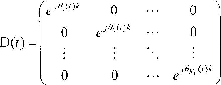
在式20中,k指出了子载波索引、根据情况针对每个酉资源指配的索引、或者根据情况针对每个包括至少一个子载波的频带指配的索引信息。并且D(t)可以对于时间(t)可变地使用或者固定地使用。通过在发射端中与式20中示出的对角矩阵相乘,可以在频域上针对每个发射天线应用循环延迟。In
式21中示出了将式20的相移矩阵与前面所述的发射功率分配预编码矩阵组合的形式。Equation 21 shows a combination of the phase shift matrix in
[式21][Formula 21]

在式21中,可以确认形式与GPSD矩阵的形式相似。然而,在本实施例中,由于假设被执行空间处理的信号与式21的预编码矩阵相乘,因此GPSD矩阵在尺寸上不同于酉矩阵。即,Nt×Nt酉矩阵用于本实施例,而Nt×R酉矩阵用于GPSD矩阵。In Equation 21, it can be confirmed that the form is similar to that of the GPSD matrix. However, in the present embodiment, since it is assumed that a signal on which spatial processing is performed is multiplied by the precoding matrix of Equation 21, the GPSD matrix is different from the unitary matrix in size. That is, the N t ×N t unitary matrix is used in this embodiment, and the N t ×R unitary matrix is used for the GPSD matrix.
换言之,不论使用什么类别的空间处理,本实施例通过与空间处理无关的酉矩阵实现发射功率分配。在该情况中,相移或循环延迟是可应用的。In other words, no matter what type of spatial processing is used, this embodiment implements transmit power allocation through a unitary matrix that is independent of spatial processing. In this case a phase shift or cyclic delay is applicable.
如前面的描述中提及的,D(t)或
为了使用式21中示出的矩阵式获得发射信号y(t),空间处理单元的输出值根据空间处理方案具有多种形式中的一个形式。如果空间处理单元的输出值是具有长度Nt的向量c(t),则发射信号y(t)可表示为式22。In order to obtain the transmitted signal y(t) using the matrix shown in Equation 21, the output value of the spatial processing unit has one of various forms according to the spatial processing scheme. If the output value of the spatial processing unit is a vector c(t) with length N t , the transmitted signal y(t) can be expressed as Equation 22.
[式22][Formula 22]

在式22中,D(t)、
在式20至22中,相位角度θi(t)(i=1,...,Nt)可根据延迟值τi(i=1,...,Nt)被表示为式23。In
[式23][Formula 23]
θi(t)=-2π/Nfft·τi(t)θ i (t) = -2π/N fft τ i (t)
在该情况中,Nfft指出了OFDM信号的子载波的数目。In this case, N fft indicates the number of subcarriers of the OFDM signal.
参考式20至23,时间延迟样本值或酉矩阵可以根据时间的消逝变化。在该情况中,时间单位可以是OFDM符号单位或预先确定的时间单位。Referring to
通过经由发射功率分配预编码矩阵对自每个发射天线发射的发射功率取平均,能够使发射机的每个天线的功率放大器的发射功率平衡。在本实施例与相移或时间延迟分集方案一起使用的情况中,可以预见到,可以解决仅在特定方向中发射发射信号的问题。By averaging the transmit power transmitted from each transmit antenna via the transmit power allocation precoding matrix, it is possible to balance the transmit power of the power amplifiers of each antenna of the transmitter. Where this embodiment is used with phase shift or time delay diversity schemes, it is foreseen that the problem of transmitting transmit signals only in certain directions can be solved.
图23是根据本发明的实施例的用于应用发射功率分配预编码矩阵的发射机和接收机的示例性框图。23 is an exemplary block diagram of a transmitter and a receiver for applying a transmit power allocation precoding matrix according to an embodiment of the present invention.
参考图23,在时域和频域上应用循环延迟分集的情况中,可以观察应用用于发射功率分配的预编码矩阵的示例。即,可以观察图21和图22中示出的实施例的组合。Referring to FIG. 23 , in the case of applying cyclic delay diversity in time domain and frequency domain, an example of applying a precoding matrix for transmission power allocation can be observed. That is, combinations of the embodiments shown in FIGS. 21 and 22 can be observed.
因此,如果在时域和频域上应用循环延迟分集,如关于GPSD和GCDD的组合的前面所述的实施例,可以一起获得在频域上应用的循环延迟的增益和在时域上应用的循环延迟的增益。Therefore, if cyclic delay diversity is applied in both time domain and frequency domain, as in the previously described embodiment regarding the combination of GPSD and GCDD, the gain of the cyclic delay applied in the frequency domain and the gain of the cyclic delay applied in the time domain can be obtained together. The gain of the loop delay.
而且,考虑到可以根据循环延迟的延迟大小获得的增益不同于在频域上应用大的循环延迟或者在时域上应用小的循环延迟的情况,可以更加高效地使用资源。Also, resources can be used more efficiently considering that gains that can be obtained according to the delay size of the cyclic delay are different from applying a large cyclic delay in the frequency domain or applying a small cyclic delay in the time domain.
将根据本发明的关于由发射机/接收机应用导频符号的示例解释如下。An example regarding application of pilot symbols by a transmitter/receiver according to the present invention is explained as follows.
图24是用于将导频符号应用于图21或图23中示出的实施例的发射机和接收机的示例性框图,并且图25是用于将导频符号应用于图22中示出的实施例的发射机和接收机的示例性框图。FIG. 24 is an exemplary block diagram of a transmitter and a receiver for applying pilot symbols to the embodiment shown in FIG. 21 or FIG. 23, and FIG. An exemplary block diagram of the transmitter and receiver of an embodiment.
参考图24和图25,在执行IFFT之前应用导频符号。因此,对于导频符号,能够使用循环延迟分集,该循环延迟分集是在IFFT处理之后针对每个天线执行的。Referring to FIG. 24 and FIG. 25, pilot symbols are applied before performing IFFT. Therefore, for the pilot symbols, cyclic delay diversity can be used, which is performed for each antenna after IFFT processing.
在该情况中,由于导频符号连同OFDM符号一起受循环延迟分集的影响,因此接收端仅配有用于GPSD的信道估计和等效信道,未额外配有用于导频符号的信道估计电路。In this case, since pilot symbols are affected by cyclic delay diversity together with OFDM symbols, the receiving end is only equipped with channel estimation and equivalent channel for GPSD, and is not additionally equipped with a channel estimation circuit for pilot symbols.
因此,有利的是,减少了接收端的复杂度。Thus, advantageously, the complexity at the receiving end is reduced.
换言之,通过对导频符号等同地使用相移或时间延迟的方式,能够解决接收机中复杂度额外增加的问题。In other words, by equally using phase shift or time delay for the pilot symbols, the problem of additional complexity increase in the receiver can be solved.
然而,在该环境下,由于相移或时间延迟未用于导频符号,因此接收机能够估计未被应用相移或时间延迟分集方案的信道。However, in this environment, since the phase shift or time delay is not used for the pilot symbols, the receiver can estimate the channel to which the phase shift or time delay diversity scheme is not applied.
图26是用于将导频符号应用于图21或图23中示出的实施例的发射机和接收机的示例性框图。FIG. 26 is an exemplary block diagram of a transmitter and a receiver for applying pilot symbols to the embodiment shown in FIG. 21 or FIG. 23 .
参考图26,在已经执行IFFT和循环延迟分集之后应用导频符号。因此,在单独的IFFT处理之后,针对天线执行的循环延迟分集未被应用于导频符号。Referring to FIG. 26, pilot symbols are applied after IFFT and cyclic delay diversity have been performed. Therefore, the cyclic delay diversity performed for the antennas is not applied to the pilot symbols after separate IFFT processing.
在该情况中,由于接收端接收未被应用循环延迟分集的导频符号,因此需要单独提供用于导频符号的信道估计电路。相比于向导频符号应用循环延迟分集的实施例,本实施例具有或多或少增加的复杂度。然而,在导频符号不受循环延迟分集,即相移的影响时,执行关于真实信道的信道估计。因此,有利的是,提高了信道估计的性能。In this case, since the receiving end receives pilot symbols to which cyclic delay diversity is not applied, it is necessary to separately provide a channel estimation circuit for the pilot symbols. This embodiment has more or less increased complexity compared to the embodiment in which cyclic delay diversity is applied to the pilot symbols. However, channel estimation on the real channel is performed when the pilot symbols are not affected by cyclic delay diversity, ie phase shift. Thus, advantageously, the performance of channel estimation is improved.
图27是用于将导频符号应用于图23中示出的实施例的发射机和接收机的示例性框图。FIG. 27 is an exemplary block diagram of a transmitter and receiver for applying pilot symbols to the embodiment shown in FIG. 23 .
参考图27,在循环延迟之前,即在频域上执行相移之前,应用导频符号。因此,在完成IFFT处理之后,频域上的循环延迟分集被应用于导频符号,并且在时域上针对每个天线执行的循环延迟分集被应用于导频符号。Referring to FIG. 27 , pilot symbols are applied before a cyclic delay, that is, before a phase shift is performed on the frequency domain. Therefore, after completion of the IFFT process, cyclic delay diversity on the frequency domain is applied to the pilot symbols, and cyclic delay diversity performed for each antenna on the time domain is applied to the pilot symbols.
图28是用于将导频符号应用于图21或图23中示出的实施例的发射机和接收机的示例性框图。FIG. 28 is an exemplary block diagram of a transmitter and a receiver for applying pilot symbols to the embodiment shown in FIG. 21 or FIG. 23 .
参考图28,对于每个天线,导频符号被应用至少两次。特别地,诸如在执行IFFT之前应用的导频符号和在完成时域上的循环延迟分集执行之后应用的导频符号之类的导频符号被应用至少两次。Referring to FIG. 28, for each antenna, pilot symbols are applied at least twice. Specifically, a pilot symbol such as a pilot symbol applied before performing IFFT and a pilot symbol applied after completing execution of cyclic delay diversity on the time domain is applied at least twice.
因此,通过向接收端发射被应用循环延迟分集的导频符号和未被应用循环延迟分集的导频符号,能够获得未被应用循环延迟分集的真实信道信息以及被应用循环延迟分集的等效信道。Therefore, by transmitting pilot symbols to which cyclic delay diversity is applied and pilot symbols to which cyclic delay diversity is not applied, the real channel information to which cyclic delay diversity is not applied and the equivalent channel to which cyclic delay diversity is applied can be obtained. .
并且,显而易见,被应用频域上的循环延迟分集和时域上的循环延迟分集的导频符号,可以与前面所述的符号应用示例一起应用或者与前面所述的符号应用示例无关。And, obviously, the pilot symbols to which the cyclic delay diversity in the frequency domain and the cyclic delay diversity in the time domain are applied can be applied together with or irrelevant to the above-mentioned symbol application examples.
工业适用性Industrial applicability
因此,本发明的基于相移的预编码方案能够自适应地应对信道状态或系统状态,与天线配置或空间复用率无关,同时保持由现有技术的相移分集或预编码方案提供的优点。Therefore, the phase-shift based precoding scheme of the present invention is capable of adaptively coping with channel state or system state, independent of antenna configuration or spatial multiplexing ratio, while maintaining the advantages provided by prior art phase-shift diversity or precoding schemes .
而且,通过针对基于相移的预编码方案选择性地采用时间相关的相位变化和循环延迟方案等,增强了发射机/接收机的复杂度并且与每个多天线方案的组合是可用的。Also, by selectively employing time-dependent phase variation and cyclic delay schemes etc. for phase-shift based precoding schemes, the complexity of the transmitter/receiver is enhanced and combinations with each multi-antenna scheme are available.
除此之外,本发明可以通过改变每个用户的通信条件而应用,由此获得了最优的通信性能。Besides, the present invention can be applied by changing the communication conditions of each user, whereby optimal communication performance is obtained.
尽管此处通过参考本发明的优选实施例描述和说明了本发明,但是对于本领域的技术人员显而易见的是,在不偏离本发明的精神和范围的前提下,可以进行多种修改和变化。因此,本发明应涵盖附属权利要求及其等效物的范围内的本发明的修改和变化。While the invention has been described and illustrated herein by reference to preferred embodiments thereof, it will be apparent to those skilled in the art that various modifications and changes can be made without departing from the spirit and scope of the invention. Thus, it is intended that the present invention cover the modifications and variations of this invention that come within the scope of the appended claims and their equivalents.
Claims (18)

Applications Claiming Priority (9)
| Application Number | Priority Date | Filing Date | Title |
|---|---|---|---|
| US86256606P | 2006-10-23 | 2006-10-23 | |
| US60/862,566 | 2006-10-23 | ||
| KR1020070034994 | 2007-04-10 | ||
| KR1020070034994A KR20080036499A (en) | 2006-10-23 | 2007-04-10 | Data transmission method using circular delay |
| US94059307P | 2007-05-29 | 2007-05-29 | |
| US60/940,593 | 2007-05-29 | ||
| KR1020070069770 | 2007-07-11 | ||
| KR1020070069770A KR20080036508A (en) | 2006-10-23 | 2007-07-11 | Data transmission method using circular delay |
| PCT/KR2007/005206 WO2008050995A2 (en) | 2006-10-23 | 2007-10-23 | Method for transmitting data using cyclic delay diversity |
Publications (1)
| Publication Number | Publication Date |
|---|---|
| CN101529777A true CN101529777A (en) | 2009-09-09 |
Family
ID=40810105
Family Applications (1)
| Application Number | Title | Priority Date | Filing Date |
|---|---|---|---|
| CNA2007800393850A Pending CN101529777A (en) | 2006-10-23 | 2007-10-23 | Method for transmitting data using cyclic delay diversity |
Country Status (4)
| Country | Link |
|---|---|
| US (1) | US20100322349A1 (en) |
| EP (1) | EP2084844A2 (en) |
| CN (1) | CN101529777A (en) |
| WO (1) | WO2008050995A2 (en) |
Cited By (4)
| Publication number | Priority date | Publication date | Assignee | Title |
|---|---|---|---|---|
| CN102474321A (en) * | 2009-09-16 | 2012-05-23 | 英特尔公司 | Spectrum Flat Delay Diversity Transmit |
| CN104364965A (en) * | 2012-06-18 | 2015-02-18 | 凯瑟雷恩工厂两合公司 | Active antenna system |
| CN108023693A (en) * | 2016-11-01 | 2018-05-11 | 上海科技大学 | A kind of uplink pilot sequence collocation method and base station |
| CN109155643A (en) * | 2016-03-07 | 2019-01-04 | 萨迪斯飞英国有限公司 | Digital beamforming systems and methods |
Families Citing this family (90)
| Publication number | Priority date | Publication date | Assignee | Title |
|---|---|---|---|---|
| US8233555B2 (en) * | 2004-05-17 | 2012-07-31 | Qualcomm Incorporated | Time varying delay diversity of OFDM |
| ATE554538T1 (en) * | 2005-12-20 | 2012-05-15 | Sharp Kk | TRANSMISSION CONTROL METHOD, BASE STATION, MOBILE UNIT AND DELAY DIVERSITY COMMUNICATION SYSTEM |
| US8780771B2 (en) * | 2007-02-06 | 2014-07-15 | Qualcomm Incorporated | Cyclic delay diversity and precoding for wireless communication |
| US8509710B2 (en) * | 2007-02-06 | 2013-08-13 | Qualcomm Incorporated | MIMO transmission with explicit and implicit cyclic delays |
| US8135083B2 (en) * | 2007-05-01 | 2012-03-13 | Nec Laboratories America, Inc. | Codebook method for a multiple input multiple output wireless system |
| BR122013003058A2 (en) * | 2007-06-19 | 2015-07-14 | Ntt Docomo Inc | Transmitter and Transmission Method |
| KR20100019948A (en) * | 2008-08-11 | 2010-02-19 | 엘지전자 주식회사 | Method of transmitting data using spatial multiplexing |
| CN101771454B (en) * | 2009-01-07 | 2014-01-01 | 中兴通讯股份有限公司 | Space diversity method and device |
| JP2011004161A (en) * | 2009-06-18 | 2011-01-06 | Sharp Corp | Communication system, communication equipment and communication method |
| US20110069775A1 (en) * | 2009-09-21 | 2011-03-24 | Ralink Technology Corporation | Signal processing method and apparatus for mimo system |
| US10027518B2 (en) * | 2010-02-12 | 2018-07-17 | Lg Electronics Inc. | Broadcasting signal transmitter/receiver and broadcasting signal transmission/reception method |
| US9887850B2 (en) | 2010-02-12 | 2018-02-06 | Lg Electronics Inc. | Broadcasting signal transmitter/receiver and broadcasting signal transmission/reception method |
| US9071285B2 (en) | 2011-05-26 | 2015-06-30 | Cohere Technologies, Inc. | Modulation and equalization in an orthonormal time-frequency shifting communications system |
| US9083595B2 (en) * | 2010-05-28 | 2015-07-14 | Cohere Technologies, Inc. | Signal modulation method resistant to echo reflections and frequency offsets |
| US9444514B2 (en) | 2010-05-28 | 2016-09-13 | Cohere Technologies, Inc. | OTFS methods of data channel characterization and uses thereof |
| US8976851B2 (en) | 2011-05-26 | 2015-03-10 | Cohere Technologies, Inc. | Modulation and equalization in an orthonormal time-frequency shifting communications system |
| US11943089B2 (en) | 2010-05-28 | 2024-03-26 | Cohere Technologies, Inc. | Modulation and equalization in an orthonormal time-shifting communications system |
| US9130638B2 (en) | 2011-05-26 | 2015-09-08 | Cohere Technologies, Inc. | Modulation and equalization in an orthonormal time-frequency shifting communications system |
| US10681568B1 (en) | 2010-05-28 | 2020-06-09 | Cohere Technologies, Inc. | Methods of data channel characterization and uses thereof |
| US9071286B2 (en) | 2011-05-26 | 2015-06-30 | Cohere Technologies, Inc. | Modulation and equalization in an orthonormal time-frequency shifting communications system |
| US10667148B1 (en) | 2010-05-28 | 2020-05-26 | Cohere Technologies, Inc. | Methods of operating and implementing wireless communications systems |
| US20130156127A1 (en) * | 2010-07-07 | 2013-06-20 | Donald L. Schilling | OFDM Synchronization and Signal Channel Estimation |
| JP5578617B2 (en) | 2010-10-18 | 2014-08-27 | パナソニック インテレクチュアル プロパティ コーポレーション オブ アメリカ | Transmission method, transmission device, reception method, and reception device |
| KR101905599B1 (en) | 2010-12-10 | 2018-10-10 | 선 페이턴트 트러스트 | Transmission method, transmitter, reception method and receiver |
| ES2662771T3 (en) | 2011-02-21 | 2018-04-09 | Sun Patent Trust | Precoding procedure, precoding device |
| US9031141B2 (en) | 2011-05-26 | 2015-05-12 | Cohere Technologies, Inc. | Modulation and equalization in an orthonormal time-frequency shifting communications system |
| US9054757B2 (en) | 2011-09-08 | 2015-06-09 | Panasonic Intellectual Property Corporation Of America | Signal generating method and signal generating apparatus |
| US20130083826A1 (en) * | 2011-09-30 | 2013-04-04 | Fujitsu Limited | Spreading data symbols among multiple layers in a mimo transmission scheme |
| US9450659B2 (en) * | 2011-11-04 | 2016-09-20 | Alcatel Lucent | Method and apparatus to generate virtual sector wide static beams using phase shift transmit diversity |
| WO2013175774A1 (en) | 2012-05-22 | 2013-11-28 | パナソニック株式会社 | Transmission method, reception method, transmitter, and receiver |
| US9929783B2 (en) | 2012-06-25 | 2018-03-27 | Cohere Technologies, Inc. | Orthogonal time frequency space modulation system |
| US10411843B2 (en) | 2012-06-25 | 2019-09-10 | Cohere Technologies, Inc. | Orthogonal time frequency space communication system compatible with OFDM |
| US10090972B2 (en) | 2012-06-25 | 2018-10-02 | Cohere Technologies, Inc. | System and method for two-dimensional equalization in an orthogonal time frequency space communication system |
| US9912507B2 (en) | 2012-06-25 | 2018-03-06 | Cohere Technologies, Inc. | Orthogonal time frequency space communication system compatible with OFDM |
| US10003487B2 (en) | 2013-03-15 | 2018-06-19 | Cohere Technologies, Inc. | Symplectic orthogonal time frequency space modulation system |
| US9967758B2 (en) | 2012-06-25 | 2018-05-08 | Cohere Technologies, Inc. | Multiple access in an orthogonal time frequency space communication system |
| US10469215B2 (en) | 2012-06-25 | 2019-11-05 | Cohere Technologies, Inc. | Orthogonal time frequency space modulation system for the Internet of Things |
| JP2015076700A (en) * | 2013-10-08 | 2015-04-20 | 株式会社Nttドコモ | Radio apparatus, radio control apparatus, and communication control method |
| BR112016016855A2 (en) | 2014-01-22 | 2017-08-08 | Huawei Tech Co Ltd | INFORMATION PROCESSING DEVICE, NETWORK NODE, AND INFORMATION PROCESSING METHOD |
| WO2016183230A1 (en) | 2015-05-11 | 2016-11-17 | Cohere Technologies | Systems and methods for symplectic orthogonal time frequency shifting modulation and transmission of data |
| US10090973B2 (en) | 2015-05-11 | 2018-10-02 | Cohere Technologies, Inc. | Multiple access in an orthogonal time frequency space communication system |
| US9866363B2 (en) | 2015-06-18 | 2018-01-09 | Cohere Technologies, Inc. | System and method for coordinated management of network access points |
| US10574317B2 (en) | 2015-06-18 | 2020-02-25 | Cohere Technologies, Inc. | System and method for providing wireless communication services using configurable broadband infrastructure shared among multiple network operators |
| CN108353052B (en) | 2015-06-27 | 2021-12-03 | 凝聚技术股份有限公司 | Orthogonal time-frequency space communication system compatible with OFDM |
| US10892547B2 (en) | 2015-07-07 | 2021-01-12 | Cohere Technologies, Inc. | Inconspicuous multi-directional antenna system configured for multiple polarization modes |
| WO2017011455A1 (en) | 2015-07-12 | 2017-01-19 | Cohere Technologies | Orthogonal time frequency space modulation over a plurality of narrow band subcarriers |
| EP3348015B1 (en) | 2015-09-07 | 2022-09-07 | Cohere Technologies, Inc. | Multiple access using orthogonal time frequency space modulation |
| CN112187329B (en) * | 2015-10-08 | 2025-01-28 | 松下电器(美国)知识产权公司 | Transmitting device and transmitting method |
| CN108781160B (en) | 2015-11-18 | 2022-04-29 | 凝聚技术公司 | Quadrature Time Frequency Spatial Modulation Technology |
| WO2017100666A1 (en) | 2015-12-09 | 2017-06-15 | Cohere Technologies | Pilot packing using complex orthogonal functions |
| EP3420641B1 (en) | 2016-02-25 | 2025-05-28 | Cohere Technologies, Inc. | Reference signal packing for wireless communications |
| WO2017165697A1 (en) | 2016-03-23 | 2017-09-28 | Cohere Technologies | Receiver-side processing of orthogonal time frequency space modulated signals |
| US9667307B1 (en) | 2016-03-31 | 2017-05-30 | Cohere Technologies | Wireless telecommunications system for high-mobility applications |
| WO2017173160A1 (en) | 2016-03-31 | 2017-10-05 | Cohere Technologies | Channel acquisition using orthogonal time frequency space modulated pilot signal |
| EP3437197B1 (en) | 2016-04-01 | 2022-03-09 | Cohere Technologies, Inc. | Tomlinson-harashima precoding in an otfs communication system |
| WO2017173389A1 (en) | 2016-04-01 | 2017-10-05 | Cohere Technologies | Iterative two dimensional equalization of orthogonal time frequency space modulated signals |
| MX2018012764A (en) | 2016-04-27 | 2019-01-10 | Panasonic Ip Corp America | Transmission device and transmission method. |
| CN109121463B (en) | 2016-04-27 | 2022-03-15 | 松下电器(美国)知识产权公司 | Transmission device and transmission method |
| WO2017201467A1 (en) | 2016-05-20 | 2017-11-23 | Cohere Technologies | Iterative channel estimation and equalization with superimposed reference signals |
| EP3264628A1 (en) * | 2016-07-01 | 2018-01-03 | Alcatel Lucent | A method for transmitting radio signals from a base station, a system and a computer program product |
| EP4362590B1 (en) | 2016-08-12 | 2026-01-14 | Cohere Technologies, Inc. | Method for multi-user multiplexing of orthogonal time frequency space signals |
| US10826728B2 (en) | 2016-08-12 | 2020-11-03 | Cohere Technologies, Inc. | Localized equalization for channels with intercarrier interference |
| EP3497799A4 (en) | 2016-08-12 | 2020-04-15 | Cohere Technologies, Inc. | MULTILEVEL ITERATIVE EQUALIZATION AND DECODING |
| US11310000B2 (en) | 2016-09-29 | 2022-04-19 | Cohere Technologies, Inc. | Transport block segmentation for multi-level codes |
| EP3520310B1 (en) | 2016-09-30 | 2021-10-27 | Cohere Technologies, Inc. | Uplink user resource allocation for orthogonal time frequency space modulation |
| EP3549200B1 (en) | 2016-12-05 | 2022-06-29 | Cohere Technologies, Inc. | Fixed wireless access using orthogonal time frequency space modulation |
| EP3566379B1 (en) | 2017-01-09 | 2024-12-11 | Cohere Technologies, Inc. | Pilot scrambling for channel estimation |
| WO2018140837A1 (en) | 2017-01-27 | 2018-08-02 | Cohere Technologies | Variable beamwidth multiband antenna |
| US10568143B2 (en) | 2017-03-28 | 2020-02-18 | Cohere Technologies, Inc. | Windowed sequence for random access method and apparatus |
| WO2018191309A1 (en) | 2017-04-11 | 2018-10-18 | Cohere Technologies | Digital communication using dispersed orthogonal time frequency space modulated signals |
| EP4109983A1 (en) | 2017-04-21 | 2022-12-28 | Cohere Technologies, Inc. | Communication techniques using quasi-static properties of wireless channels |
| WO2018200567A1 (en) | 2017-04-24 | 2018-11-01 | Cohere Technologies | Multibeam antenna designs and operation |
| EP3616341A4 (en) | 2017-04-24 | 2020-12-30 | Cohere Technologies, Inc. | Digital communication using lattice division multiplexing |
| JP7215995B2 (en) * | 2017-04-24 | 2023-01-31 | パナソニック インテレクチュアル プロパティ コーポレーション オブ アメリカ | Transmission device and transmission method |
| WO2019014332A1 (en) | 2017-07-12 | 2019-01-17 | Cohere Technologies | Data modulation schemes based on the zak transform |
| WO2019032605A1 (en) | 2017-08-11 | 2019-02-14 | Cohere Technologies | Ray tracing technique for wireless channel measurements |
| WO2019036492A1 (en) | 2017-08-14 | 2019-02-21 | Cohere Technologies | Transmission resource allocation by splitting physical resource blocks |
| CN111279337B (en) | 2017-09-06 | 2023-09-26 | 凝聚技术公司 | Wireless communication method implemented by wireless communication receiver device |
| WO2019051427A1 (en) | 2017-09-11 | 2019-03-14 | Cohere Technologies, Inc. | Wireless local area networks using orthogonal time frequency space modulation |
| CN111095883B (en) | 2017-09-15 | 2023-04-07 | 凝聚技术公司 | Synchronization in orthogonal time-frequency space signal receivers |
| WO2019060596A2 (en) | 2017-09-20 | 2019-03-28 | Cohere Technologies, Inc. | Low cost electromagnetic feed network |
| WO2019068053A1 (en) | 2017-09-29 | 2019-04-04 | Cohere Technologies, Inc. | Forward error correction using non-binary low density parity check codes |
| EP4362344A3 (en) | 2017-11-01 | 2024-07-31 | Cohere Technologies, Inc. | Precoding in wireless systems using orthogonal time frequency space multiplexing |
| US11184122B2 (en) | 2017-12-04 | 2021-11-23 | Cohere Technologies, Inc. | Implementation of orthogonal time frequency space modulation for wireless communications |
| US11632270B2 (en) | 2018-02-08 | 2023-04-18 | Cohere Technologies, Inc. | Aspects of channel estimation for orthogonal time frequency space modulation for wireless communications |
| EP3763050A4 (en) | 2018-03-08 | 2021-11-24 | Cohere Technologies, Inc. | Scheduling multi-user mimo transmissions in fixed wireless access systems |
| EP4485869A3 (en) | 2018-06-13 | 2025-03-26 | Cohere Technologies, Inc. | Reciprocal calibration for channel estimation based on second-order statistics |
| US11522600B1 (en) | 2018-08-01 | 2022-12-06 | Cohere Technologies, Inc. | Airborne RF-head system |
| CN110971275B (en) * | 2018-09-28 | 2021-11-23 | 大唐移动通信设备有限公司 | Uplink transmission method, uplink transmission scheduling method and device |
| US12335081B2 (en) | 2021-04-29 | 2025-06-17 | Cohere Technologies, Inc. | Ultra wide band signals using orthogonal time frequency space modulation |
Family Cites Families (5)
| Publication number | Priority date | Publication date | Assignee | Title |
|---|---|---|---|---|
| US7978778B2 (en) * | 2004-09-03 | 2011-07-12 | Qualcomm, Incorporated | Receiver structures for spatial spreading with space-time or space-frequency transmit diversity |
| US7894548B2 (en) * | 2004-09-03 | 2011-02-22 | Qualcomm Incorporated | Spatial spreading with space-time and space-frequency transmit diversity schemes for a wireless communication system |
| JP2008017143A (en) * | 2006-07-05 | 2008-01-24 | Toshiba Corp | Radio receiving apparatus and method |
| US8503560B2 (en) * | 2006-10-02 | 2013-08-06 | Samsung Electronics Co., Ltd | System and method for performing precoding in a wireless communication system |
| US8131228B2 (en) * | 2007-08-01 | 2012-03-06 | Telefonaktiebolaget Lm Ericsson (Publ) | Interference based phase shift precoding for OFDM |
-
2007
- 2007-10-23 CN CNA2007800393850A patent/CN101529777A/en active Pending
- 2007-10-23 US US12/446,565 patent/US20100322349A1/en not_active Abandoned
- 2007-10-23 WO PCT/KR2007/005206 patent/WO2008050995A2/en not_active Ceased
- 2007-10-23 EP EP07833515A patent/EP2084844A2/en not_active Withdrawn
Cited By (6)
| Publication number | Priority date | Publication date | Assignee | Title |
|---|---|---|---|---|
| CN102474321A (en) * | 2009-09-16 | 2012-05-23 | 英特尔公司 | Spectrum Flat Delay Diversity Transmit |
| CN102474321B (en) * | 2009-09-16 | 2014-10-29 | 英特尔公司 | Spectrally flat delay diversity transmission method and device |
| CN104364965A (en) * | 2012-06-18 | 2015-02-18 | 凯瑟雷恩工厂两合公司 | Active antenna system |
| CN109155643A (en) * | 2016-03-07 | 2019-01-04 | 萨迪斯飞英国有限公司 | Digital beamforming systems and methods |
| CN108023693A (en) * | 2016-11-01 | 2018-05-11 | 上海科技大学 | A kind of uplink pilot sequence collocation method and base station |
| CN108023693B (en) * | 2016-11-01 | 2020-12-18 | 上海科技大学 | A kind of uplink pilot sequence configuration method and base station |
Also Published As
| Publication number | Publication date |
|---|---|
| WO2008050995A2 (en) | 2008-05-02 |
| EP2084844A2 (en) | 2009-08-05 |
| US20100322349A1 (en) | 2010-12-23 |
| WO2008050995A3 (en) | 2008-12-11 |
Similar Documents
| Publication | Publication Date | Title |
|---|---|---|
| CN101529777A (en) | Method for transmitting data using cyclic delay diversity | |
| EP3905542B1 (en) | Data transmitting and receiving method using phase shift based precoding and transceiver supporting the same | |
| KR100934662B1 (en) | Data Transceiving Method Using Phase Shift Based Precoding and Transceiver | |
| CN101461205B (en) | Signal generation using phase-shift based pre-coding | |
| CN101663837B (en) | Method for transmitting signals in a multi-antenna communication system | |
| US8175182B2 (en) | Method for transmitting data using phase shift based precoding and transceiver supporting the same | |
| EP2272180B1 (en) | Method for transmitting and receiving signals in open-loop spatial multiplexing mode | |
| US8107455B2 (en) | Method for transmitting data in multiple antenna system | |
| US20100226417A1 (en) | Data transmitting and receiving method using phase shift based precoding and transceiver supporting the same | |
| US20110274200A1 (en) | Method for transmitting/receiving data in a multiple-input multiple-output system using multi-carrier | |
| JP2011529660A (en) | Data transmission method in multi-antenna system | |
| KR20080036499A (en) | Data transmission method using circular delay | |
| TWI416888B (en) | Data transmitting and receiving method using phase shift based precoding and transceiver supporting the same | |
| JP2010517463A5 (en) | ||
| HK40056487A (en) | Data transmitting and receiving method using phase shift based precoding and transceiver supporting the same | |
| KR20080036508A (en) | Data transmission method using circular delay |
Legal Events
| Date | Code | Title | Description |
|---|---|---|---|
| C06 | Publication | ||
| PB01 | Publication | ||
| C10 | Entry into substantive examination | ||
| SE01 | Entry into force of request for substantive examination | ||
| C02 | Deemed withdrawal of patent application after publication (patent law 2001) | ||
| WD01 | Invention patent application deemed withdrawn after publication |
Application publication date: 20090909 |