CN101516282A - Orthopedic plate system - Google Patents
Orthopedic plate system Download PDFInfo
- Publication number
- CN101516282A CN101516282A CNA2007800343635A CN200780034363A CN101516282A CN 101516282 A CN101516282 A CN 101516282A CN A2007800343635 A CNA2007800343635 A CN A2007800343635A CN 200780034363 A CN200780034363 A CN 200780034363A CN 101516282 A CN101516282 A CN 101516282A
- Authority
- CN
- China
- Prior art keywords
- plate
- plate member
- recess
- threaded
- diameter
- Prior art date
- Legal status (The legal status is an assumption and is not a legal conclusion. Google has not performed a legal analysis and makes no representation as to the accuracy of the status listed.)
- Pending
Links
Images


Classifications
-
- A—HUMAN NECESSITIES
- A61—MEDICAL OR VETERINARY SCIENCE; HYGIENE
- A61B—DIAGNOSIS; SURGERY; IDENTIFICATION
- A61B17/00—Surgical instruments, devices or methods
- A61B17/56—Surgical instruments or methods for treatment of bones or joints; Devices specially adapted therefor
- A61B17/58—Surgical instruments or methods for treatment of bones or joints; Devices specially adapted therefor for osteosynthesis, e.g. bone plates, screws or setting implements
- A61B17/68—Internal fixation devices, including fasteners and spinal fixators, even if a part thereof projects from the skin
- A61B17/70—Spinal positioners or stabilisers, e.g. stabilisers comprising fluid filler in an implant
- A61B17/7049—Connectors, not bearing on the vertebrae, for linking longitudinal elements together
-
- A—HUMAN NECESSITIES
- A61—MEDICAL OR VETERINARY SCIENCE; HYGIENE
- A61B—DIAGNOSIS; SURGERY; IDENTIFICATION
- A61B17/00—Surgical instruments, devices or methods
- A61B17/56—Surgical instruments or methods for treatment of bones or joints; Devices specially adapted therefor
- A61B17/58—Surgical instruments or methods for treatment of bones or joints; Devices specially adapted therefor for osteosynthesis, e.g. bone plates, screws or setting implements
- A61B17/68—Internal fixation devices, including fasteners and spinal fixators, even if a part thereof projects from the skin
- A61B17/70—Spinal positioners or stabilisers, e.g. stabilisers comprising fluid filler in an implant
- A61B17/7001—Screws or hooks combined with longitudinal elements which do not contact vertebrae
- A61B17/7002—Longitudinal elements, e.g. rods
- A61B17/7004—Longitudinal elements, e.g. rods with a cross-section which varies along its length
- A61B17/7007—Parts of the longitudinal elements, e.g. their ends, being specially adapted to fit around the screw or hook heads
-
- A—HUMAN NECESSITIES
- A61—MEDICAL OR VETERINARY SCIENCE; HYGIENE
- A61B—DIAGNOSIS; SURGERY; IDENTIFICATION
- A61B17/00—Surgical instruments, devices or methods
- A61B17/56—Surgical instruments or methods for treatment of bones or joints; Devices specially adapted therefor
- A61B17/58—Surgical instruments or methods for treatment of bones or joints; Devices specially adapted therefor for osteosynthesis, e.g. bone plates, screws or setting implements
- A61B17/68—Internal fixation devices, including fasteners and spinal fixators, even if a part thereof projects from the skin
- A61B17/70—Spinal positioners or stabilisers, e.g. stabilisers comprising fluid filler in an implant
- A61B17/7001—Screws or hooks combined with longitudinal elements which do not contact vertebrae
- A61B17/7035—Screws or hooks, wherein a rod-clamping part and a bone-anchoring part can pivot relative to each other
- A61B17/7037—Screws or hooks, wherein a rod-clamping part and a bone-anchoring part can pivot relative to each other wherein pivoting is blocked when the rod is clamped
-
- A—HUMAN NECESSITIES
- A61—MEDICAL OR VETERINARY SCIENCE; HYGIENE
- A61B—DIAGNOSIS; SURGERY; IDENTIFICATION
- A61B17/00—Surgical instruments, devices or methods
- A61B17/56—Surgical instruments or methods for treatment of bones or joints; Devices specially adapted therefor
- A61B17/58—Surgical instruments or methods for treatment of bones or joints; Devices specially adapted therefor for osteosynthesis, e.g. bone plates, screws or setting implements
- A61B17/68—Internal fixation devices, including fasteners and spinal fixators, even if a part thereof projects from the skin
- A61B17/70—Spinal positioners or stabilisers, e.g. stabilisers comprising fluid filler in an implant
- A61B17/7001—Screws or hooks combined with longitudinal elements which do not contact vertebrae
- A61B17/7044—Screws or hooks combined with longitudinal elements which do not contact vertebrae also having plates, staples or washers bearing on the vertebrae
-
- A—HUMAN NECESSITIES
- A61—MEDICAL OR VETERINARY SCIENCE; HYGIENE
- A61B—DIAGNOSIS; SURGERY; IDENTIFICATION
- A61B17/00—Surgical instruments, devices or methods
- A61B17/56—Surgical instruments or methods for treatment of bones or joints; Devices specially adapted therefor
- A61B17/58—Surgical instruments or methods for treatment of bones or joints; Devices specially adapted therefor for osteosynthesis, e.g. bone plates, screws or setting implements
- A61B17/68—Internal fixation devices, including fasteners and spinal fixators, even if a part thereof projects from the skin
- A61B17/70—Spinal positioners or stabilisers, e.g. stabilisers comprising fluid filler in an implant
- A61B17/7047—Clamps comprising opposed elements which grasp one vertebra between them
Landscapes
- Health & Medical Sciences (AREA)
- Orthopedic Medicine & Surgery (AREA)
- Life Sciences & Earth Sciences (AREA)
- Neurology (AREA)
- Surgery (AREA)
- Heart & Thoracic Surgery (AREA)
- Engineering & Computer Science (AREA)
- Biomedical Technology (AREA)
- Nuclear Medicine, Radiotherapy & Molecular Imaging (AREA)
- Medical Informatics (AREA)
- Molecular Biology (AREA)
- Animal Behavior & Ethology (AREA)
- General Health & Medical Sciences (AREA)
- Public Health (AREA)
- Veterinary Medicine (AREA)
- Surgical Instruments (AREA)
Abstract
公开了一种整形外科医疗设备和方法,其具有圆柱形整形外科板和夹具以及用于将板固定到例如骨组织的组织上的固定构件。在一个实施例中,所述板包括是圆柱形的侧面和端部,并且所述夹具适于适配到其上。也公开了横向连接构件形式的附加设备以及可与整形外科板一同使用的连接板。同样描述了用于使用所公开设备的方法。
A plastic surgery medical device and method are disclosed, comprising a cylindrical plastic surgery plate and clamps, as well as fixation members for securing the plate to tissue such as bone. In one embodiment, the plate includes cylindrical sides and ends, and the clamps are adapted to fit thereon. Additional devices in the form of lateral connecting members and connecting plates for use with the plastic surgery plate are also disclosed. Methods for using the disclosed device are also described.
Description
背景技术 Background technique
在整形外科手术领域内,细长板或杆可以被固定到骨头上从而将它们保持并支撑在给定位置。例如,在融合(fuse)损伤椎骨的过程中,外科医生根据需要将椎骨定位在修正位置内。平板(即具有平的上和下侧面的板)被放置于邻近或抵靠骨头,并且使用骨锚来将板固定到骨头上。骨螺钉或螺栓可以被用作骨锚,并且通过在一个(多个)骨头内钻一个或多个孔并且将锚螺纹地拧入所述孔内来实现这种锚的放置。锚可以被螺纹地拧入贯通板的孔内,或者当螺纹地拧入孔内之后板可以被置于锚周围的位置。锚和板被彼此固定从而防止相对运动。这样,可以以正确的校准来保持并/或支撑骨头以愈合。In the field of orthopedic surgery, elongated plates or rods can be fixed to bones to hold and support them in a given position. For example, during the process of fusing injured vertebrae, the surgeon positions the vertebrae in the corrected position as desired. A plate (ie, a plate with flat upper and lower sides) is placed adjacent to or against the bone, and bone anchors are used to secure the plate to the bone. Bone screws or bolts may be used as bone anchors, and placement of such anchors is achieved by drilling one or more holes in the bone(s) and threading the anchors into the holes. The anchors may be threaded into holes through the plate, or the plate may be placed in place around the anchors after being threaded into the holes. The anchor and plate are secured to each other against relative movement. In this way, the bone can be held in the correct alignment and/or supported to heal.
其他整形外科系统使用杆来连接骨锚并且提供对于例如椎骨的组织的稳定性。这样的杆可以例如沿椎骨被放置并且具有轮廓从而将骨头保持在所需位置内并支撑所述骨头。Other orthopedic systems use rods to connect bone anchors and provide stability to tissues such as vertebrae. Such rods may, for example, be placed along the vertebrae and contoured to hold and support the bone in a desired position.
附图说明 Description of drawings
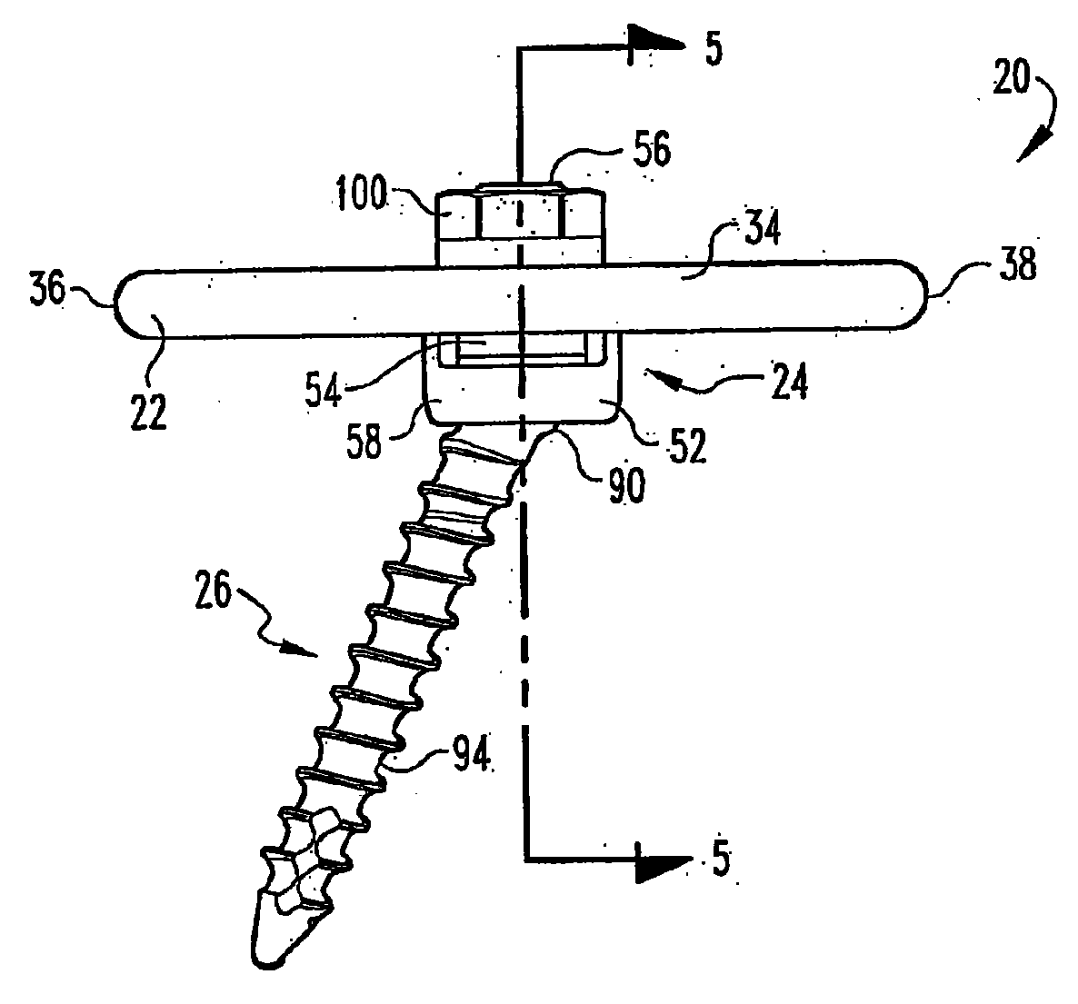
图1是整形外科板系统的一个实施例的侧视图。Figure 1 is a side view of one embodiment of an orthopedic board system.
图2是图1实施例的俯视图。Fig. 2 is a top view of the embodiment of Fig. 1 .
图3是图1实施例的端视图。FIG. 3 is an end view of the embodiment of FIG. 1 .
图4是沿图2中线4-4截取并从箭头方向观察的图1实施例的横截面视图。4 is a cross-sectional view of the embodiment of FIG. 1 taken along line 4-4 in FIG. 2 and viewed from the direction of the arrow.
图5是沿图1中线5-5截取并从箭头方向观察的图1实施例的横截面视图。5 is a cross-sectional view of the embodiment of FIG. 1 taken along line 5-5 in FIG. 1 and viewed in the direction of the arrows.
图6是整形外科板系统的一个实施例的侧视图。Figure 6 is a side view of one embodiment of an orthopedic plate system.
图7是图6实施例的俯视图。FIG. 7 is a top view of the embodiment of FIG. 6 .
图8是图6实施例的端视图。FIG. 8 is an end view of the embodiment of FIG. 6 .
图9是沿图7中线9-9截取并从箭头方向观察的图6实施例的横截面视图。9 is a cross-sectional view of the embodiment of FIG. 6 taken along line 9-9 in FIG. 7 and viewed from the direction of the arrow.
图10是沿图6中线10-10截取并从箭头方向观察的图6实施例的横截面视图。Figure 10 is a cross-sectional view of the embodiment of Figure 6 taken along line 10-10 in Figure 6 and viewed from the direction of the arrow.
图11是整形外科板系统的一个实施例的侧视图。Figure 11 is a side view of one embodiment of an orthopedic plate system.
图12是图11实施例的俯视图。Fig. 12 is a top view of the embodiment of Fig. 11 .
图13是图11实施例的端视图。FIG. 13 is an end view of the embodiment of FIG. 11. FIG.
图14是沿图12中线14-14截取并从箭头方向观察的图11实施例的横截面视图。14 is a cross-sectional view of the embodiment of FIG. 11 taken along line 14-14 in FIG. 12 and viewed from the direction of the arrow.
图15是沿图11中线10-10截取并从箭头方向观察的图11实施例的横截面视图。15 is a cross-sectional view of the embodiment of FIG. 11 taken along line 10-10 in FIG. 11 and viewed from the direction of the arrow.
图16是整形外科板系统的一个实施例的立体图。Figure 16 is a perspective view of one embodiment of an orthopedic plate system.
图16A是可以用于图16实施例的设备的立体图。FIG. 16A is a perspective view of a device that may be used with the embodiment of FIG. 16 .
图17是整形外科板系统的一个实施例的立体图。Figure 17 is a perspective view of one embodiment of an orthopedic plate system.
具体实施方式 Detailed ways
为了有助于理解公开内容的原理,将针对在附图中所示的实施例进行说明,并且特定语言被用于描述相同特征。不过应当理解不意于限制权利要求的范围,本公开内容所涉及领域内的技术人员通常能够想到对于所述装置的这种改变及进一步改进以及对于这里描述的公开内容的原理的进一步应用。To facilitate an understanding of the principles of the disclosure, the description will be directed to the embodiments shown in the drawings, and specific language is used to describe the same features. It should be understood, however, that no limitation of the scope of the claims is intended and that such changes and further modifications to the described devices and further applications of the principles of the disclosure described herein will generally occur to those skilled in the art to which the disclosure relates.
一般参考图1-5,描述了整形外科植入系统20的一个实施例。在这个实施例中,植入系统20包括板构件22、至少一个夹具24以及连接到夹具24上的骨固定构件26。可以在不背离本公开内容范围的情况下使用不同数量的任意这些元件。例如可以使用彼此连同的多个板构件22,并且取决于板构件的尺寸、形状或其他构造、要被解决的医学问题以及/或者其他因素,可以使用附加夹具24和骨固定构件26。Referring generally to FIGS. 1-5, one embodiment of an
在一个实施例中,板构件22一般是细长椭圆形的形式,且该细长椭圆形具有第一侧面或轨32、第二侧面或轨34、第一端部36和第二端部38。在所述实施例中,侧面32、34和端部36、38限定或围绕空间40。每个侧面32、34均具有在端部36和38之间的长度,并且具体实施例的侧面32、34在端部36和38之间的其全部长度上基本笔直。侧面32、34进一步是圆柱形的,例如垂直于侧面32、34纵轴线的横截面是基本圆形的。类似地,端部36和38是基本圆柱形的,例如垂直于中心轴线的横截面也是基本圆形的。在所述实施例中,侧面32、34均具有彼此相等且等于端部36、38的直径的相应直径。因此,板构件22可以被看作是弯曲成一个连续的基本的椭圆形以便其端部相接的大体圆柱形单杆。其也可以被看作是两个平行圆柱形杆且端部弯曲以彼此相接。由于缺少拐角或者材料集中度,所以侧面32、34的圆柱形形状可以使得板构件22更容易地绕任意轴线或在扭矩下弯曲,且同时不需要对两个杆进行切割、组装和操作。这也使得能够将板构件22用于被设计与圆柱形杆一同使用的各种植入物。当然,每个侧面的直径可以彼此不同并且/或者不同于端部的直径,并且可以进行其他的结构改变。In one embodiment, the
夹具24的一个实施例可以被用于板构件22。图1-5中所示的夹具24的实施例包括轭构件52和冠构件54。轭构件52具有比下部58稍薄的上部56。在具体实施例中,上部56被成尺寸为能够被插入通过板构件22的空间40,并且具有螺纹部分60。在具体实施例中,上部具有基本等于板构件22的侧面32和34的最近点之间的距离的宽度尺寸。上部56也可以包括开口或孔口62。至少一些孔口62可以包括印迹(print)或轮廓64(例如,六边形印迹、德士龙(TORX)印迹或类似表面)或其他方式以便被工具接合。在所述实施例中,轭构件52的下部58具有腔66、朝向腔66的开口端部的槽68以及斜边70。腔66被成尺寸成容纳骨固定构件(例如构件26)的至少一部分,如下面进一步描述的。腔66可以连通在上部56内的孔口62,并且也可以朝向轭构件52的侧面开口且使得表面72、74大体面向板构件22。示出的环构件76位于槽68内。当在槽68内时环构件76的内尺寸小于固定构件在腔66内部分的外尺寸。环构件76可以是为不受应力的结构的大体C形且其基本是平的或波浪形的,并且或者其稍大于槽68的直径,这样环构件76被保持在槽68中。可替换地,环构件76可以具有其他构造或特性,例如由形状记忆材料制成。One embodiment of a
冠构件54的所述实施例具有上表面78、可以是基本球形的内表面82以及延伸指状件84,其中孔80延伸通过所述上表面78。冠构件54大体被成尺寸为可移动地适配在腔66内,这样环构件76可以在冠构件54和斜边70之间。孔80与腔66连通,并且在所述实施例中孔80基本对齐于轭构件52的上部56的孔口62。在所述实施例中,冠构件54的指状件84至少稍稍延伸越过表面72、74。The illustrated embodiment of the
同样示出了骨固定构件26的一个实施例。大体而言,骨固定构件26的所述实施例包括头部90以及螺纹杆部94,所述头部90具有例如上面关于印迹64所述的内驱动印迹92。头部90部分上基本是球形,并且包括可以为圆周的一个或多个脊96。如上所述,头部90被成尺寸为适配在腔66内并且通过环构件76被保持在该处,这样骨固定构件26可以关于轭构件52多轴向地被定位。虽然骨固定构件26在这个实施例中被示出为螺杆时,不过其可以更换为钩或其他类型的整形外科植入物或装置。An embodiment of a
在所述实施例中也提供螺母100。螺母100具有内螺纹102、下开口104,该下开口104可以部分为斜面且部分为基本圆柱形,并且螺母100也可以包括加宽的下部件106,该下部件106横向延伸稍远于具有外平面以驱动的上部件108。上部件108可以包括不同的印迹或构造以用于驱动。A
在使用中,夹具24和骨固定构件26可以先于手术被连接,或者在对于外科医生或其他人方便的任意时间被连接。在将骨固定构件26插入腔66之上或之前,冠构件54被插入到轭52的腔66内。环构件76可以被置于绕杆94并且被插入通过斜面开口70进入腔66。如果合适的话,环构件76可以被压缩,例如如果是C形构件且其不受应力直径大于腔66直径,如上所述。环构件76进入腔66内并且被至少部分地置于槽68内。因此,所述实施例将骨固定构件26的头90置于轭构件52的腔66内的环构件76和冠构件54之间。In use, the
骨固定构件26和夹具24被附连到组织上,例如椎骨。在一个实施例中,可以在椎骨中钻一个尺寸适于骨固定构件26的孔。螺纹杆94被插入孔内,并且在一个实施例中带有合适配置尖端的工具(未示出)被插入印迹92且也被插入穿过在骨固定构件26和夹具24预装配时轭构件52的孔口62及冠构件54的孔80,并且被转动从而将杆94螺纹拧入骨头内。当杆94被螺纹拧入骨头内到达所需深度时,工具被从轭构件52上移除。夹具24可以绕骨固定构件26的头90被旋转并/或转动从而根据外科医生的需要到达一相对位置。
之后通过将轭构件52的上部56插入通过板构件22的空间40,从而将板构件22置于夹具24之上。板构件22的侧面32、34可以邻接冠构件54的指状件84。根据外科医生的需要,可以相对于夹具24来调整板构件22,并且/或者可以相对于骨固定构件26来调整板构件22和夹具24的组合。螺母100被螺纹拧到轭构件52的上部56上并且被紧固抵靠板构件22。拧紧螺母100将板构件22压向冠构件54,并且骨固定构件26被夹持在冠构件54的表面82和环构件76之间。The
可以理解的是,另一个夹具24和骨固定构件26可以被置于例如相邻椎骨的其他组织中,并且基本如上所述被连接板构件22。附加地或可选择地,其他类型的骨植入物或整形外科装置可以被连接到相邻骨头或其他组织,或者可以简化板构件22之间的连接形式并进一步简化整形外科植入物或器械。It will be appreciated that another
板构件22可以与各种夹具、骨固定构件及其他植入结构一同使用。图6-10中是其中一些夹具124和骨固定构件126的实施例。夹具124包括带有一对腿156的U形轭构件152以及其中有孔口162的底座158。在所述实施例中,孔口162具有向外展开的基本圆锥形上段164a和下段164b,该下段164b也可以是基本圆锥形的并且向外展开的或者可以是基本球形的或其他构造或其组合。每个腿156与底座158形成一凹陷165。在一个具体实施例中,该凹陷165是弯曲的且其曲率半径基本等于板构件22的侧面32、34的半径。如这个实施例所示,在一个实施例中凹进165邻近或邻接板构件22的侧面的稍小于四分之一圆周从而更容易地将板构件22置于轭构件152旁。在凹进164邻近或邻接板构件22的侧面的稍大于四分之一圆周的实施例中,轭构件152可以卡咬在板构件22的侧面32、34上,或者端部36、38中的一个被插入腿156之间并且轭构件152可以沿板构件22滑动到所述相对位置。
骨固定构件126是螺栓,且该螺栓具有在螺纹杆194和上螺纹部分195之间的中间头部190,其中该螺纹杆194用于连接例如椎骨的组织。这样的螺栓的示例公开于美国专利No.6,280,445,其全部内容并入本文以供参考。头部190可以具有基本球形上部197,该上部197邻接下孔口段164b并可以相对于该下孔口段164b转动。上螺纹部分195包括用于驱动骨固定构件126的内印迹199。可以如上所述相对于印迹64和92来配置印迹199。The bone fixation member 126 is a bolt with an
在这个实施例中也示出了螺母200。螺母200类似于美国专利No.6,315,779中所述,该专利的全部内容被并入本文以供参考。螺母200的所述实施例包括内螺纹202、围绕下开口204的下圆柱形裙部203以及加宽的下部件206,该下部件206横向延伸稍远于具有外平面以驱动的上部件208。上部件108可以包括不同的印迹或构造以用于驱动。螺母200的底侧209是向外展开的并且可以是基本圆锥形的。除螺母200之外,可以提供垫圈210,且其具有平面底侧212、弯曲或圆锥形的上侧面214以及孔或狭槽216,该孔或狭槽216允许骨固定构件126的上螺纹部分195相对于垫圈210至少在一个平面内运动。螺母200和垫圈210如果一起使用的话则可以形成预组装单元,并且裙部203可以悬垂或以其他方式扩展以防止螺母200从垫圈210上脱落并同时保留螺母200沿垫圈210运动且相对于垫圈210旋转的能力。
在使用中,可以先于手术或者在对于外科医生或其他人方便的任意时间时,将夹具124连接于骨固定构件126和板构件22中的任意一者或两者。在一个实施例中,骨固定构件126被附连到例如椎骨的组织上。例如,可以在椎骨中钻一个尺寸适于骨固定构件26的螺纹杆194的孔。螺纹杆194被插入孔内,并且在一个实施例中带有合适配置尖端的工具(未示出)被插入印迹192且之后被转动从而将螺纹杆194螺纹拧入骨头内。当杆194被螺纹拧入骨头内到达所需深度时,工具被移除。In use, the
如果之前没有连接夹具124的话,则夹具124被置于骨固定构件126上从而上螺纹部分延伸在夹具124之上并且中间头190邻接夹具124,例如至少部分地在孔口部162b内。夹具124可以根据外科医生的需要绕骨固定构件126的头190旋转并/或转动到相对位置。如果之前没有将板构件22连接到夹具124的话,则板构件124可以被置于骨固定构件126之上并且邻近夹具124。在该位置,板构件22的侧面32、34至少部分地位于夹具124的凹进165内,并且骨固定构件126的上螺纹部分195延伸穿过板构件22的空间40。If the
可以根据外科医生的需要,至少通过沿狭槽216的平面和/或板构件22的长度来转动骨固定构件126,从而相对于骨固定构件126调整板构件22和夹具124。螺母200和垫圈210被置于骨固定构件126的上螺纹部分195之上,并且螺母200被螺纹拧向下并被拧紧从而将垫圈210压向板构件22。拧紧螺母100也拉动骨固定构件126从而其头190将夹具124压向板构件22,从而锁定结构。可以理解的是,可以在不使用垫圈210或使用不同垫圈的情况下使用螺母200。可以进一步理解的是,在其他实施例中,带有或不带有例如垫圈210的垫圈的螺母100或其他类型螺母可以与固定构件126一同使用。例如,可以提供具有基本平面底面的如螺母200′(图11-15)的螺母。使用例如螺母200′的螺母来锁定板构件22、夹具124和骨固定构件126可以基本限制或阻止骨固定构件126相对于夹具124和板构件22的平面或多轴向定位。
可以如上述或其他实施例中为实施例单独提供附加部件或工具包。例如,如图16-17所示,示出的横向连接件300连接板构件22。连接件300包括连接构件302、柱304和螺母306。连接构件302包括块状部分308,该块状部分308具有贯穿其中的第一开口310以容纳至少部分细长构件(例如整形外科棒R),该块状部分308还具有第二开口312以用于螺纹拧入定位螺钉(未示出),该定位螺钉相对于块状部件308锁定细长构件R。连接构件302进一步包括从块状部分308横向延伸出的延伸部分316,并且在具体实施例中延伸部分316基本垂直于块状部分308的表面。在所述实施例中,延伸部分316的一个侧面包括两个凹进318,所述凹进318可以具有基本圆柱形形状并且可以具有基本相同于板构件22的侧面32、34的直径的直径。凹进318用于容纳板构件22的侧面32、34的至少一部分,并且在一个实施例中,凹进318的壁接触板构件22的相应侧面32、34。如图16-17的实施例中所示,凹进318在延伸部分316实际背向块状部分308和细长构件R的侧面上。可以理解的是,凹进318可以在延伸部分316的任意侧面上。贯穿凹进318之间的延伸部分316提供一孔。Additional parts or kits may be provided separately for embodiments as described above or in other embodiments. For example, as shown in FIGS. 16-17 , a
在所述实施例中,柱304包括带有基本圆柱形上部322和下凸缘324的主体320。上部322可以具有螺纹并且包括印迹326,该印迹326例如内六边形、德士龙形或其他构造以容纳工具。凸缘324大体从主体320横向延伸出,不过其可以绕主体320周界的其他部分延伸或者绕主体320的全部周界延伸。在具体实施例中,凸缘324具有端部328,该端部328相对于凸缘324的其他部分成角度倾斜,并且可以是基本平面的、可以形成部分球形表面或者可以是其他构造。如下面进一步描述,凸缘324被成尺寸成至少部分端部328可以邻接板构件22的侧面32、34的部分。螺母306是内螺纹的并且成尺寸成被螺纹拧到柱304的上部322上。In the depicted embodiment, post 304 includes a
可以在外科医生方便时先于手术或者在手术过程中,将连接件300连接于板构件22。延伸部分316被置于板构件22之上或之下,这样板构件22的侧面32、34至少部分地在延伸部分316的凹进318内。柱304的上部322被插入穿过板构件22的空间40以及孔319,这样凸缘324的端部328邻近或邻接板构件22的侧面32、34。螺母306被螺纹拧到延伸部分316上并紧固抵靠延伸部分316(在所述实施例中),从而将板构件22锁定在延伸部分316和凸缘324之间。可选择地,连接件300可以被连接在板构件22的下面(即相反于图16-17中所示),并且螺母306可以直接接触板构件22并且凸缘324邻接延伸部分316。板构件22可以被锁定在螺母306和凸缘324之间。在将连接件300连接到板构件22之前或之后,例如脊骨棒的细长构件R被插入到块状部分308内并且通过定位螺钉(未示出)锁定。
可以被连接到板构件22的另一个设备是附加连接或稳定构件,例如图16中所示的连接板400的实施例。在该实施例中,连接板400包括用于附连到板构件22上的连结部分402以及用于连接到其他组织或装置(例如骶骨或植入骶骨内的设备)上的板部分404。连结部分402包括贯通其中的孔406以及贯通其中的狭槽408,其中狭槽408位于基本垂直于孔406的轴线的平面内。狭槽408足够宽以允许板构件22从其中穿过,这样板构件22的空间40和孔406连通。如果孔406是内螺纹的,则可以提供定位螺钉409来相对板构件22锁定连结部分402。可选择地,不管孔406是否是螺纹的,均可以提供柱304和螺母306并用以相对于板构件22锁定连结部分402,基本如上面关于连接构件300和板构件22的描述。Another device that may be connected to
在所述实施例中,板部分404具有贯穿其中的至少一个孔410,该孔410适于容纳被植入骶骨或其他骨头内的骨螺钉,或者可以适于容纳其他类型的整形外科植入物或器械。在图16的实施例中,两个骨螺钉412延伸穿过一个或多个孔410。可以理解的是,提供穿过板部分404的骨螺钉,且为定位螺钉提供独立螺纹孔,该定位螺钉的头与骨螺钉的头交叠从而防止骨螺钉的松动或者防止将骨螺钉从骨头中拉出。板部分303和连结部分402相对彼此被定向以保证某种整形外科校正手术或解剖学置位。例如,连接板400的所述实施例示出了不与连结部分402成平面的板部分404,并且在其间形成钝角。当与被连接到下腰椎或骶椎(例如L5或S1)的板构件22一同使用时这样的结构是有利的,其中外科医生也希望横向连接到骶骨或其他骨头。连结部分402和板部分404之间的角可以变化(通过弯曲连接板400或者通过在工具包内提供各种角度的连接板400),从而最大地满足解剖学条件或者病人的需要。在其他实施例中,板部分404和连结部分402可以相对彼此基本成平面、可以扭曲从而他们不成平面但是公用一个纵轴线、或者以其他方式配置。In the depicted embodiment, the
可以当外科医生方便时,在外科手术之前或在外科手术过程期间,将连接板400连接到板22。根据外科医生的需要,板构件22的端部36或38被插入穿过连结部分402的狭槽408,这样连接板400被置于板构件22上。当孔406具有螺纹并且提供螺钉409时,螺钉409被螺纹地拧入孔406内并且抵靠板构件22,从而将板构件22压向连结部分402以将他们锁定到一起。如果使用柱304和螺母306,则柱304的上部322被插入穿过连结部分402的孔406并且穿过板构件22的空间40,这样凸缘324邻近或邻接连结部分402,并且上部322从连结部分402延伸出。螺母306被螺纹地拧到柱304上并且被拧紧抵靠连结部分402,从而挤压狭槽408以将板构件22锁定于其中。可选择地,孔406和/或凸缘324可以被成尺寸车使得凸缘324可以适配穿过至少部分孔406并且凸缘324的端部328邻近或邻接板构件22的侧面32、34。拧紧螺母306抵靠连结部分402导致板构件22被夹持在凸缘324和连结部分402之间。在将连结部分402连结到板构件22上之前或之后,可以将板部分404连结到组织或其他植入物或设备上。然而,当将板构件22固定到骨头或其他组织之前该板构件22可以在一个或多个方向内运动的情况下,如果首先通过板部分404将其连接到组织或设备且之后连接到板构件22的话,则可以更加容易地使用连接板400。
现在大体参考图17,示出了被连接到板构件22上的连接板400′的另一个实施例。连接板400′基本相同于连接板400,且多了一个第二板部分404a。在这个实施例中,连结部分402在板部分404和404a之间,并且板部分404a相对于连结部分402成角度,这样板部分404和404a不成平面而是基本平行。板部分404a包括孔410a,螺钉412a或其他植入物或装置可以延伸穿过该孔410a例如进入骨头。也可以在板部分404a中发现关于板部分404在上面描述的其他方面。Referring now generally to FIG. 17 , another embodiment of a
可以看出,在各图中所示的部件不限于与其所描述或具体说明的的实施例一同使用,而是可以用于其他实施例或与其他实施例结合使用。因此,例如一个板构件22可以与一个夹具24和以及夹具124一同使用,并且关于夹具24所示的部件可以用于夹具124。It can be seen that the components shown in the various figures are not limited to use with the embodiment described or illustrated therein, but can be used in or in conjunction with other embodiments. Thus, for example, one
本发明的植入系统的部件可以被制成包含单一部件的多个尺寸和多种构造的工具包的形式,或者被制成包含本发明系统中所包括的所有部件的多个尺寸和多种构造的工具包的形式。这样的工具包可以包括,例如,一组具有不同长度和具有不同数量或定向的狭槽/或钻孔的细长构件22和/或100。在细长构件100的情况下,工具包可以包括一组沿纵轴线106具有不同弯曲度的细长构件。也可以提供在这里公开的垫圈、螺栓、螺钉及螺母的组。此外,也可以包括与本发明的植入系统的部件兼容的例如扳手或螺丝起子的工具。The components of the implant system of the present invention may be manufactured in the form of a kit containing a single component in multiple sizes and configurations, or in multiple sizes and multiple configurations containing all the components included in the system of the present invention. Constructed in the form of a kit. Such a kit may include, for example, a set of
本发明的装置优选地由例如不锈钢、钛、某些塑料或其他公知材料的结实的生物相容性材料构成。The devices of the present invention are preferably constructed of strong biocompatible materials such as stainless steel, titanium, certain plastics, or other well known materials.
虽然在附图和上述说明中已经详细示出并描述了本发明,不过其应被认为是示意性的并且不限制其特征,应该理解的是,仅示出并描述了优选实施例并且所有的改变和改进均落入所需要保护的本发明的精神范围内。While the invention has been shown and described in detail in the drawings and foregoing description, it is to be considered illustrative and not limiting in character, it being understood that only preferred embodiments have been shown and described and that all Changes and improvements are within the spirit of the claimed invention.
Claims (25)
Applications Claiming Priority (2)
| Application Number | Priority Date | Filing Date | Title |
|---|---|---|---|
| US11/522,832 | 2006-09-18 | ||
| US11/522,832 US7362452B2 (en) | 2005-09-19 | 2006-09-18 | Method of adjusting the operating region of a tool component to a pre-determined element |
Publications (1)
| Publication Number | Publication Date |
|---|---|
| CN101516282A true CN101516282A (en) | 2009-08-26 |
Family
ID=39092557
Family Applications (1)
| Application Number | Title | Priority Date | Filing Date |
|---|---|---|---|
| CNA2007800343635A Pending CN101516282A (en) | 2006-09-18 | 2007-09-17 | Orthopedic plate system |
Country Status (6)
| Country | Link |
|---|---|
| EP (1) | EP2079378A2 (en) |
| JP (1) | JP2010503498A (en) |
| KR (1) | KR101166614B1 (en) |
| CN (1) | CN101516282A (en) |
| AU (1) | AU2007297420A1 (en) |
| WO (1) | WO2008036578A2 (en) |
Cited By (1)
| Publication number | Priority date | Publication date | Assignee | Title |
|---|---|---|---|---|
| CN102670295A (en) * | 2012-06-04 | 2012-09-19 | 上海拓腾医疗器械有限公司 | Internal fixation device of spine |
Families Citing this family (2)
| Publication number | Priority date | Publication date | Assignee | Title |
|---|---|---|---|---|
| EP2174608B1 (en) * | 2008-10-08 | 2012-08-01 | Biedermann Technologies GmbH & Co. KG | Bone anchoring device and stabilization device for bone parts or vertebrae |
| EP3701892B1 (en) * | 2017-10-24 | 2025-02-26 | Paulo Tadeu Maia Cavali | Guide device for attachment and transfixation of sliding plates for dynamic implants |
Family Cites Families (9)
| Publication number | Priority date | Publication date | Assignee | Title |
|---|---|---|---|---|
| US6176861B1 (en) * | 1994-10-25 | 2001-01-23 | Sdgi Holdings, Inc. | Modular spinal system |
| US6569164B1 (en) * | 1998-04-29 | 2003-05-27 | Stryker Spine | Spinal osteosynthesis system for anterior fixation |
| DE19848715C1 (en) | 1998-10-22 | 2000-08-24 | Aesculap Ag & Co Kg | Osteo-synthetic holding system has locking units for the holding rods of different dimensions for the holding rods to allow adjustments to the setting of the bones or fragments before final clamping |
| FR2801778B1 (en) * | 1999-12-03 | 2002-02-08 | Spinevision | CONNECTION ASSEMBLY FOR THE FIELD OF RACHIDIAN OSTEOSYNTHESIS |
| DE10132712B4 (en) * | 2001-07-05 | 2004-03-25 | Aesculap Ag & Co. Kg | Bone screw and osteosynthesis device |
| FR2831048B1 (en) * | 2001-10-18 | 2004-09-17 | Ldr Medical | PROGRESSIVE APPROACH OSTEOSYNTHESIS DEVICE AND PRE-ASSEMBLY PROCESS |
| US20060079892A1 (en) * | 2001-10-31 | 2006-04-13 | Suranjan Roychowdhury | Adjustable tandem connectors for corrective devices for the spinal column and other bones and joints |
| FR2832620B1 (en) | 2001-11-27 | 2004-01-23 | Eurosurgical | CONNECTOR FOR VERTEBRAL ANCHORAGE SYSTEM |
| US7794477B2 (en) * | 2004-10-05 | 2010-09-14 | Warsaw Orthopedic, Inc. | Spinal implants and methods with extended multi-axial anchor assemblies |
-
2007
- 2007-09-17 CN CNA2007800343635A patent/CN101516282A/en active Pending
- 2007-09-17 JP JP2009528520A patent/JP2010503498A/en active Pending
- 2007-09-17 EP EP07842581A patent/EP2079378A2/en not_active Withdrawn
- 2007-09-17 KR KR1020097006948A patent/KR101166614B1/en not_active Expired - Fee Related
- 2007-09-17 WO PCT/US2007/078604 patent/WO2008036578A2/en not_active Ceased
- 2007-09-17 AU AU2007297420A patent/AU2007297420A1/en not_active Abandoned
Cited By (2)
| Publication number | Priority date | Publication date | Assignee | Title |
|---|---|---|---|---|
| CN102670295A (en) * | 2012-06-04 | 2012-09-19 | 上海拓腾医疗器械有限公司 | Internal fixation device of spine |
| CN102670295B (en) * | 2012-06-04 | 2015-01-07 | 上海三友医疗器械有限公司 | Internal fixation device of spine |
Also Published As
| Publication number | Publication date |
|---|---|
| KR20090068229A (en) | 2009-06-25 |
| WO2008036578A2 (en) | 2008-03-27 |
| WO2008036578A3 (en) | 2008-05-08 |
| JP2010503498A (en) | 2010-02-04 |
| AU2007297420A1 (en) | 2008-03-27 |
| EP2079378A2 (en) | 2009-07-22 |
| KR101166614B1 (en) | 2012-07-18 |
Similar Documents
| Publication | Publication Date | Title |
|---|---|---|
| US5415659A (en) | Spinal fixation system and pedicle clamp | |
| US20200179009A1 (en) | Orthopedic fastener for stabilization and fixation | |
| US7766946B2 (en) | Device for securing spinal rods | |
| JP4536118B2 (en) | Spine implant with a wide range of multiaxial fastener assemblies | |
| US7850715B2 (en) | Orthopedic implant apparatus | |
| US7722645B2 (en) | Pedicle screw spinal fixation device | |
| JP4390709B2 (en) | Variable angle adaptive plate | |
| EP1635722B1 (en) | Variable offset spinal fixation system | |
| US6689133B2 (en) | Multi-axial bone anchor system | |
| US7837714B2 (en) | Methods and devices for the interconnection of bone attachment devices | |
| EP1954206B1 (en) | Dorsal adjusting multi-rod connector | |
| US6858031B2 (en) | Multi-axial bone anchor system | |
| AU2006242212B2 (en) | Device for interconnecting components in spinal instrumentation | |
| US5928232A (en) | Spinal fixation system | |
| US8361125B2 (en) | Spinal implants with multi-axial anchor assembly and methods | |
| CN100593392C (en) | Sternal reconstruction system | |
| JP2008538088A (en) | Spinal rod connector | |
| JP2006517846A (en) | Spinal plate with integral rod connector | |
| CN101005809A (en) | Sternal reconstruction system | |
| US8398684B2 (en) | Bone anchoring member | |
| US8128665B2 (en) | Orthopedic implant apparatus | |
| US8672983B2 (en) | Orthopedic plate system | |
| US7850716B2 (en) | Adjustable interconnection device | |
| CN101516282A (en) | Orthopedic plate system | |
| JP2008539821A (en) | Multi-axis anchor assembly and method for spinal implants |
Legal Events
| Date | Code | Title | Description |
|---|---|---|---|
| C06 | Publication | ||
| PB01 | Publication | ||
| C10 | Entry into substantive examination | ||
| SE01 | Entry into force of request for substantive examination | ||
| C02 | Deemed withdrawal of patent application after publication (patent law 2001) | ||
| WD01 | Invention patent application deemed withdrawn after publication |
Open date: 20090826 |