CN101509962A - Magnetic induction measurement method and apparatus - Google Patents
Magnetic induction measurement method and apparatus Download PDFInfo
- Publication number
- CN101509962A CN101509962A CNA2009100585245A CN200910058524A CN101509962A CN 101509962 A CN101509962 A CN 101509962A CN A2009100585245 A CNA2009100585245 A CN A2009100585245A CN 200910058524 A CN200910058524 A CN 200910058524A CN 101509962 A CN101509962 A CN 101509962A
- Authority
- CN
- China
- Prior art keywords
- light
- mode
- intensity
- converted
- fbg
- Prior art date
- Legal status (The legal status is an assumption and is not a legal conclusion. Google has not performed a legal analysis and makes no representation as to the accuracy of the status listed.)
- Granted
Links
- 230000005291 magnetic effect Effects 0.000 title claims abstract description 128
- 230000006698 induction Effects 0.000 title claims abstract description 53
- 238000000691 measurement method Methods 0.000 title description 8
- 239000013307 optical fiber Substances 0.000 claims abstract description 27
- 238000000034 method Methods 0.000 claims abstract description 25
- 230000009471 action Effects 0.000 claims abstract description 7
- 239000000835 fiber Substances 0.000 claims description 19
- 238000001228 spectrum Methods 0.000 claims description 17
- 230000003287 optical effect Effects 0.000 claims description 16
- 230000010287 polarization Effects 0.000 claims description 16
- 238000006243 chemical reaction Methods 0.000 claims description 15
- 230000000694 effects Effects 0.000 abstract description 15
- 238000005259 measurement Methods 0.000 abstract description 15
- 238000005516 engineering process Methods 0.000 abstract description 4
- 239000000463 material Substances 0.000 description 10
- 239000000523 sample Substances 0.000 description 6
- 238000000411 transmission spectrum Methods 0.000 description 6
- 230000005540 biological transmission Effects 0.000 description 4
- 230000008878 coupling Effects 0.000 description 4
- 238000010168 coupling process Methods 0.000 description 4
- 238000005859 coupling reaction Methods 0.000 description 4
- 238000010586 diagram Methods 0.000 description 4
- 230000003321 amplification Effects 0.000 description 3
- 238000001514 detection method Methods 0.000 description 3
- 238000003199 nucleic acid amplification method Methods 0.000 description 3
- 230000008569 process Effects 0.000 description 3
- 230000035945 sensitivity Effects 0.000 description 3
- 230000008859 change Effects 0.000 description 2
- 239000004065 semiconductor Substances 0.000 description 2
- XUIMIQQOPSSXEZ-UHFFFAOYSA-N Silicon Chemical compound [Si] XUIMIQQOPSSXEZ-UHFFFAOYSA-N 0.000 description 1
- 238000004458 analytical method Methods 0.000 description 1
- CRQQGFGUEAVUIL-UHFFFAOYSA-N chlorothalonil Chemical compound ClC1=C(Cl)C(C#N)=C(Cl)C(C#N)=C1Cl CRQQGFGUEAVUIL-UHFFFAOYSA-N 0.000 description 1
- 239000011248 coating agent Substances 0.000 description 1
- 238000000576 coating method Methods 0.000 description 1
- 230000007797 corrosion Effects 0.000 description 1
- 238000005260 corrosion Methods 0.000 description 1
- 230000002708 enhancing effect Effects 0.000 description 1
- 230000006355 external stress Effects 0.000 description 1
- 230000010365 information processing Effects 0.000 description 1
- 238000009413 insulation Methods 0.000 description 1
- 230000003993 interaction Effects 0.000 description 1
- 239000005304 optical glass Substances 0.000 description 1
- 230000001902 propagating effect Effects 0.000 description 1
- 229910052710 silicon Inorganic materials 0.000 description 1
- 239000010703 silicon Substances 0.000 description 1
- 230000003595 spectral effect Effects 0.000 description 1
Images


Landscapes
- Measuring Magnetic Variables (AREA)
Abstract
一种磁感应强度的测量方法及装置,属于电子信息技术中的光纤传感技术领域,涉及磁感应强度的测量方法及装置。本发明基于FBG结构与磁光法拉第效应,通过测量已知光强的线偏振光入射到已知磁感应强度B的磁场作用下的FBG后的模式转换反射光(或透射光)的相对强度,得到FBG模式转换反射光(或透射光)的相对强度与外加磁场磁感应强度B的线性关系;然后通过测量已知光强的线偏振光入射到待测磁感应强度B的磁场作用下的FBG后的模式转换反射光(或透射光)的相对强度,并根据前述所得的线性关系,即可确定待测磁场的磁感应强度B的大小。本发明具有测量精度高、简单易用、成本低廉的特点,尤其适用于电磁铁磁极中磁场大小的测量和高压电流产生的磁场的测量。

A method and device for measuring magnetic induction intensity, which belong to the technical field of optical fiber sensing in electronic information technology, and relate to a method and device for measuring magnetic induction intensity. The present invention is based on the FBG structure and the magneto-optical Faraday effect, by measuring the relative intensity of the mode-converted reflected light (or transmitted light) after the linearly polarized light of known light intensity is incident on the FBG under the action of a magnetic field of known magnetic induction intensity B, to obtain The FBG mode converts the linear relationship between the relative intensity of the reflected light (or transmitted light) and the magnetic induction intensity B of the applied magnetic field; then by measuring the linearly polarized light of known light intensity incident to the FBG mode under the action of the magnetic field of the magnetic induction intensity B to be measured The magnitude of the magnetic induction B of the magnetic field to be measured can be determined by converting the relative intensity of the reflected light (or transmitted light) and according to the linear relationship obtained above. The invention has the characteristics of high measurement accuracy, simple and easy to use, and low cost, and is especially suitable for measuring the magnitude of the magnetic field in the magnetic pole of the electromagnet and the magnetic field generated by the high-voltage current.
Description
技术领域 technical field
本发明属于电子信息技术中的光纤传感技术领域,涉及磁感应强度的测量方法及装置,具体地说,是涉及一种通过检测磁场作用下光纤光栅(FBG)的反射光谱(或透射光谱)中模式转换光的强度来测量磁感应强度的方法及装置。The invention belongs to the technical field of optical fiber sensing in electronic information technology, and relates to a method and device for measuring magnetic induction intensity, in particular to a method for detecting the reflection spectrum (or transmission spectrum) of a fiber grating (FBG) under the action of a magnetic field. A method and device for measuring magnetic induction intensity by mode-converting the intensity of light.
背景技术 Background technique
光纤光栅作为传感元器件,除了具有普通光纤传感器不受电磁干扰、灵敏度高、带宽宽、质量轻、体积小、耐腐蚀、易于复用、可远距离遥测、能埋入工程结构等优点外,而且易于集成,能够实现多点分布式测量,克服了传统传感器测量成本高、精度低的缺点。As a sensing component, fiber optic gratings have the advantages of being immune to electromagnetic interference, high sensitivity, wide bandwidth, light weight, small size, corrosion resistance, easy reuse, long-distance telemetry, and being embedded in engineering structures. , and easy to integrate, it can realize multi-point distributed measurement, which overcomes the disadvantages of high cost and low precision of traditional sensor measurement.
目前,基于光纤材料的磁场测量方法,主要包括:(a)基于磁致伸缩效应的光纤型磁场传感器,在磁场作用下,磁致伸缩材料的伸缩带动光纤折射率和长度发生变化,通过检测其相位变化来间接测量磁场大小;(b)基于磁光法拉第效应的光纤型磁场传感器,当光波通过置于磁场中的磁光光纤(如YIG或者掺Tb玻璃光纤等)后,其法拉第旋转角发生一定程度的偏转,通过测量法拉第旋转角的变化来间接测量磁场大小;(c)基于磁致伸缩效应的FBG型磁场传感器,在光纤光栅外涂上磁致伸缩材料或者将光纤光栅镶入磁致伸缩材料中形成磁场传感头,通过磁力效应对光纤光栅施加应力,再利用光纤光栅对外应力的敏感性,达到磁场测量的目的;(d)基于磁光法拉第效应的FBG型磁场传感器,其原理是在外加磁场作用下,光纤光栅中的左旋和右旋圆偏振光的布拉格反射波长发生漂移,通过测出波长漂移量来确定磁场的大小。上述四种磁场测量方法均存在以下两个问题:一是,对用作磁场探头的光纤(或光纤光栅)材料要求苛刻,材料的磁光效应必须足够强;相对于普通光纤,这种光纤的拉制比较困难,价格昂贵;二是,光信号检测系统极其复杂且不稳定。At present, the magnetic field measurement methods based on optical fiber materials mainly include: (a) optical fiber magnetic field sensor based on magnetostrictive effect. Phase change to indirectly measure the magnitude of the magnetic field; (b) a fiber-optic magnetic field sensor based on the magneto-optical Faraday effect. A certain degree of deflection, by measuring the change of Faraday rotation angle to indirectly measure the size of the magnetic field; (c) FBG type magnetic field sensor based on the magnetostrictive effect, coating the fiber grating with magnetostrictive material or inserting the fiber grating into the magnetostrictive The magnetic field sensor head is formed in the stretchable material, and the fiber grating is stressed by the magnetic effect, and then the sensitivity of the fiber grating to the external stress is used to achieve the purpose of magnetic field measurement; (d) FBG magnetic field sensor based on the magneto-optical Faraday effect, its principle Under the action of an external magnetic field, the Bragg reflection wavelength of the left-handed and right-handed circularly polarized light in the fiber grating drifts, and the magnitude of the magnetic field is determined by measuring the wavelength shift. The above-mentioned four kinds of magnetic field measurement methods all have the following two problems: one is that the optical fiber (or fiber grating) material used as a magnetic field probe is demanding, and the magneto-optical effect of the material must be strong enough; Drawing is more difficult and expensive; second, the optical signal detection system is extremely complex and unstable.
发明内容 Contents of the invention
本发明基于FBG结构与磁光法拉第效应共同作用的原理,提供一种简单易用的磁场(磁感应强度)的测量方法;并且,根据该方法所建立的磁感应强度的测量装置具有结构简单、易于实现、成本低廉的特点。The present invention is based on the principle that the FBG structure and the magneto-optical Faraday effect work together, and provides a simple and easy-to-use method for measuring the magnetic field (magnetic induction); and, the measuring device for the magnetic induction established according to the method has a simple structure and is easy to realize , Low cost characteristics.
本发明磁场测量方法基于FBG结构与磁光法拉第效应共同作用的原理。磁光法拉第效应使FBG中同一传播方向的光波之间发生偏振模式转换,宏观上表现为光波偏振面发生旋转,即θ=VBL,其中θ为光波偏振面的旋转角度,V为FBG材料的verdet常数,B为外加磁感应强度,L为FBG材料与磁场的相互作用长度。另外,FBG结构使正向和反向传播的偏振光发生耦合。这样由外加磁场引起的偏振模式转换便反映到FBG的反射光谱(或透射光谱)上,其结果是在FBG的带隙边缘出现两个尖锐的谱线,该尖锐线谱强度即为模式转换光强度。数值分析表明:由于模式转换效应的引入,需对传统FBG中的光传输方程进行修正,得到光场的耦合模方程,再利用FBG满足的边界条件,推导得到模式转换反射光(或透射光)的相对强度,该模式转换光的相对强度正比于θ,进而正比于外加磁场B,根据模式转换反射光(或透射光)的相对强度与外加磁场B之间的线性关系,可以通过测量模式转换反射光(或透射光)的相对强度来测量外加磁场磁感应强度的大小。The magnetic field measurement method of the present invention is based on the principle that the FBG structure and the magneto-optical Faraday effect work together. The magneto-optical Faraday effect causes the polarization mode conversion between the light waves in the same propagation direction in the FBG. Macroscopically, the polarization plane of the light wave is rotated, that is, θ=VBL, where θ is the rotation angle of the polarization plane of the light wave, and V is the verdet of the FBG material. constant, B is the external magnetic induction intensity, and L is the interaction length between the FBG material and the magnetic field. In addition, the FBG structure couples the forward and reverse propagating polarized light. In this way, the polarization mode conversion caused by the external magnetic field is reflected on the reflection spectrum (or transmission spectrum) of the FBG. As a result, two sharp spectral lines appear at the edge of the band gap of the FBG, and the intensity of the sharp line spectrum is the mode conversion light. strength. Numerical analysis shows that: due to the introduction of the mode conversion effect, the light transmission equation in the traditional FBG needs to be corrected to obtain the coupled mode equation of the light field, and then use the boundary conditions satisfied by the FBG to derive the mode converted reflected light (or transmitted light) The relative intensity of the mode-converted light is proportional to θ, and then proportional to the external magnetic field B. According to the linear relationship between the relative intensity of the mode-converted reflected light (or transmitted light) and the external magnetic field B, the mode conversion can be measured The relative intensity of reflected light (or transmitted light) is used to measure the magnitude of the magnetic induction of the applied magnetic field.
根据上述原理,本发明的技术方案是:According to above-mentioned principle, technical scheme of the present invention is:
一种磁感应强度的测量方法,如图1所示,包括以下步骤:A kind of measuring method of magnetic induction intensity, as shown in Figure 1, comprises the following steps:
步骤1:采用两个或两个以上已知磁感应强度B的磁场作用于FBG,测量已知光强的线偏振光入射到FBG后的模式转换反射光或模式转换透射光的强度,并将模式转换反射光或模式转换透射光的强度换算成相对于入射线偏振光光强的相对强度,绘制出FBG模式转换反射光或模式转换透射光的相对强度与外加磁场磁感应强度B的线性关系。Step 1: Use two or more magnetic fields with known magnetic induction intensity B to act on the FBG, measure the intensity of the mode-converted reflected light or the mode-converted transmitted light after the linearly polarized light of known light intensity is incident on the FBG, and compare the mode The intensity of converted reflected light or mode-converted transmitted light was converted into relative intensity relative to the intensity of incident ray polarized light, and the linear relationship between the relative intensity of FBG mode-converted reflected light or mode-converted transmitted light and the magnetic induction intensity B of the applied magnetic field was drawn.
步骤2:将待测磁感应强度B的磁场作用于FBG,测量已知光强的线偏振光入射到FBG后的模式转换反射光或模式转换透射光的相对强度,根据步骤1所得的FBG模式转换反射光或透射光的相对强度与外加磁场磁感应强度的线性关系确定待测磁场的磁感应强度B的大小。Step 2: Apply the magnetic field of the magnetic induction intensity B to be measured to the FBG, measure the relative intensity of the mode-converted reflected light or the mode-converted transmitted light after the linearly polarized light of known light intensity is incident on the FBG, according to the FBG mode conversion obtained in step 1 The linear relationship between the relative intensity of reflected light or transmitted light and the magnetic induction of the applied magnetic field determines the magnitude of the magnetic induction B of the magnetic field to be measured.
上述技术方案中,所述已知光强的线偏振光可用宽谱光源的输出光经光纤起偏器起偏获得;所述模式转换反射光或模式转换透射光可由与所述光纤起偏器偏振方向垂直的光纤检偏器检偏获得。In the above technical solution, the linearly polarized light of known light intensity can be obtained by polarizing the output light of a broadband light source through an optical fiber polarizer; the mode-converted reflected light or mode-converted transmitted light can be obtained by combining with the optical fiber polarizer The polarization is obtained by analyzing the polarization with a fiber optic analyzer perpendicular to the polarization direction.
本发明所述的磁感应强度的测量方法,基于FBG结构与磁光法拉第效应共同作用的原理,可采用普通硅光纤做成的FBG作为磁场传感探头,而无需先前磁场传感技术中选用的强磁致伸缩效应材料光纤、YIG光纤或者掺Tb磁光玻璃光纤等特种材料FBG,从而使得这种磁场测量方法更加实用、易行。The method for measuring the magnetic induction intensity described in the present invention is based on the principle that the FBG structure and the magneto-optic Faraday effect work together, and the FBG made of ordinary silicon optical fiber can be used as the magnetic field sensing probe without the need for the strong magnetic field sensing technology used in the previous magnetic field sensing technology. Magnetostrictive effect material optical fiber, YIG optical fiber or Tb-doped magneto-optical glass optical fiber and other special materials FBG, thus making this magnetic field measurement method more practical and easy.
附图说明 Description of drawings
图1是本发明提供的一种磁感应强度的测量方法的流程示意图。Fig. 1 is a schematic flowchart of a method for measuring magnetic induction provided by the present invention.
图2是根据本发明一种磁感应强度的测量方法确定的FBG模式转换反射光或模式转换透射光的相对强度与外加磁场磁感应强度B的线性关系。2 is a linear relationship between the relative intensity of FBG mode-converted reflected light or mode-converted transmitted light and the magnetic induction intensity B of an applied magnetic field determined according to a method for measuring magnetic induction of the present invention.
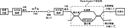
图3是根据本发明一种磁感应强度的测量方法确定的透射式磁感应强度测量装置示意图。Fig. 3 is a schematic diagram of a transmission-type magnetic induction measuring device determined according to a method for measuring magnetic induction of the present invention.
图4是根据本发明一种磁感应强度的测量方法确定的反射式磁感应强度测量装置示意图。Fig. 4 is a schematic diagram of a reflective magnetic induction measuring device determined according to a method for measuring magnetic induction of the present invention.
图5是运用本发明一种磁感应强度的测量方法测量电磁铁磁极打孔处磁感应强度的示意图。Fig. 5 is a schematic diagram of measuring the magnetic induction at the hole of the electromagnet pole by using a method for measuring the magnetic induction of the present invention.
图6是是运用本发明一种磁感应强度的测量方法测量大电流产生磁场的磁感应强度的示意图。6 is a schematic diagram of measuring the magnetic induction of a magnetic field generated by a large current by using a method for measuring magnetic induction of the present invention.
具体实施方式 Detailed ways
具体实施方式一Specific implementation mode one
根据本发明提供的一种磁感应强度的测量方法,一种透射式磁感应强度测量装置,如图3所示,包括宽谱光源、光纤起偏器、光纤光栅(FBG)、光纤检偏器、可调法珀半导体光放大器(FP-SOA)和光谱仪。所述宽谱光源的输出光经光纤起偏器起偏后入射到FBG中,FBG在外加磁场作用下的透射光经与所述光纤起偏器偏振方向垂直的光纤检偏器检偏后转换成模式转换透射光;所述模式转换透射光经可调FP-SOA放大后输入光谱仪。According to a method for measuring magnetic induction provided by the present invention, a transmission-type magnetic induction measuring device, as shown in Figure 3, includes a wide-spectrum light source, an optical fiber polarizer, a fiber grating (FBG), an optical fiber analyzer, and Tuned Faber semiconductor optical amplifier (FP-SOA) and spectrometer. The output light of the broadband light source is incident on the FBG after being polarized by the optical fiber polarizer, and the transmitted light of the FBG under the action of an external magnetic field is analyzed by the optical fiber analyzer perpendicular to the polarization direction of the optical fiber polarizer and converted into mode-converted transmitted light; the mode-converted transmitted light is amplified by an adjustable FP-SOA and then input to a spectrometer.
上述技术方案中,检偏器和光谱仪之间只用到一个可调FP-SOA。实际测量过程中,为了增加FP-SOA的光放大效果,以便于光谱仪检测模式转换光的强度,可在可调FP-SOA两段通过耦合器连接一个直通臂,形成一个含有可调FP-SOA的M-Z干涉仪结构对模式转换光进行功率放大,在干涉仪输出端(即直通臂输出端或耦合臂输出端)使用光谱仪测量模式转换光的强度,这样可以提高测量精度。In the above technical solution, only one adjustable FP-SOA is used between the polarizer and the spectrometer. In the actual measurement process, in order to increase the optical amplification effect of the FP-SOA so that the spectrometer can detect the intensity of the mode-converted light, a straight-through arm can be connected through a coupler at the two sections of the adjustable FP-SOA to form a The M-Z interferometer structure amplifies the power of the mode-converted light, and uses a spectrometer to measure the intensity of the mode-converted light at the output end of the interferometer (ie, the output end of the through arm or the output end of the coupling arm), which can improve the measurement accuracy.
具体实施方式二Specific implementation mode two
根据本发明提供的一种磁感应强度的测量方法,一种反射式磁感应强度测量装置,如图4所示,包括宽谱光源、光纤起偏器、光环形器、光纤光栅(FBG)、光纤检偏器、可调法珀半导体光放大器(FP-SOA)和光谱仪。所述宽谱光源的输出光经光纤起偏器起偏并经光环形器入射到FBG中,FBG在外加磁场作用下的反射光经光环形器、并经与所述光纤起偏器偏振方向垂直的光纤检偏器检偏后转换成模式转换反射光;所述模式转换反射光经可调FP-SOA放大后输入光谱仪。According to a method for measuring magnetic induction provided by the present invention, a reflective magnetic induction measuring device, as shown in Figure 4, includes a wide-spectrum light source, an optical fiber polarizer, an optical circulator, a fiber grating (FBG), an optical fiber detector Polarizer, Farpert-tunable Semiconductor Optical Amplifier (FP-SOA) and spectrometer. The output light of the broadband light source is polarized by the optical fiber polarizer and is incident into the FBG through the optical circulator. The vertical optical fiber analyzer converts the reflected light into mode conversion after analyzing the polarization; the mode converted reflected light is amplified by the adjustable FP-SOA and then input to the spectrometer.
上述技术方案中,检偏器和光谱仪之间只用到一个可调FP-SOA。实际测量过程中,为了增加FP-SOA的光放大效果,以便于光谱仪检测模式转换光的强度,可在可调FP-SOA两段通过耦合器连接一个直通臂,形成一个含有可调FP-SOA的M-Z干涉仪结构对模式转换光进行功率放大,在干涉仪输出端(即直通臂输出端或耦合臂输出端)使用光谱仪测量模式转换光的强度,这样可以提高测量精度。In the above technical solution, only one adjustable FP-SOA is used between the polarizer and the spectrometer. In the actual measurement process, in order to increase the optical amplification effect of the FP-SOA so that the spectrometer can detect the intensity of the mode-converted light, a straight-through arm can be connected through a coupler at the two sections of the adjustable FP-SOA to form a The M-Z interferometer structure amplifies the power of the mode-converted light, and uses a spectrometer to measure the intensity of the mode-converted light at the output end of the interferometer (ie, the output end of the through arm or the output end of the coupling arm), which can improve the measurement accuracy.
上述两种实施方式所述的磁感应强度测量装置实现磁场测量的过程如下:宽谱光源发出一段光波(如C波段,1530-1565nm),经光纤起偏器输出的线偏振光(如x方向的线偏振光)入射到普通FBG探头中,FBG相当于一个梳状滤波器,在外加磁场作用下FBG可使入射线偏振光发生偏振模转换,模式转换透射光(或反射光)经与所述光纤起偏器偏振方向垂直的光纤检偏器检偏后(如y方向的线偏振光),此时FBG透射谱(或反射谱)中含有尖锐线谱结构的模式转换光,根据上述模式转换光强度与外加磁场B之间的线性关系,通过检测FBG反射谱(或透射谱)中偏振模式转换光的强度并换算成相对于入射线偏振光光强的相对强度,即可测量出外加磁场大小。The magnetic induction intensity measuring device described in the two above-mentioned embodiments realizes the process of magnetic field measurement as follows: a broad-spectrum light source emits a section of light waves (such as C-band, 1530-1565nm), and the linearly polarized light (such as the x direction) output by the optical fiber polarizer Linearly polarized light) is incident into the ordinary FBG probe, and the FBG is equivalent to a comb filter. Under the action of an external magnetic field, the FBG can cause the polarization mode conversion of the incident linearly polarized light, and the mode converted transmitted light (or reflected light) is combined with the described After analyzing the polarization of the fiber optic polarizer whose polarization direction is vertical (such as linearly polarized light in the y direction), at this time, the FBG transmission spectrum (or reflection spectrum) contains mode-converted light with a sharp line spectrum structure. According to the above-mentioned mode conversion The linear relationship between the light intensity and the applied magnetic field B can be measured by detecting the intensity of the polarization mode conversion light in the FBG reflection spectrum (or transmission spectrum) and converting it into the relative intensity of the incident line polarized light intensity. size.
由于普通FBG材料中磁光法拉第效应微弱,所导致的模式转换光强度也较弱,一般的检测设备如光谱仪、光功率计等不易直接探测出来。本发明磁场传感装置中,采用基于M-Z干涉仪结构的可调FP-SOA来放大较弱的模式转换光。可调FP-SOA的作用在于:1)与发生偏振模式转换的反射(或透射)线谱精确对准;2)增强反射(或透射)线谱强度。采用了M-Z干涉仪结构放大光信号的优点是:1)可以获得比直接采用FP-SOA作为光放大更大的增益,灵敏度高;2)该结构对相位差不敏感,当确定好可调FP-SOA的工作点后,则无需再调整两臂的相位延迟。Due to the weak magneto-optical Faraday effect in ordinary FBG materials, the resulting mode-converted light intensity is also weak, and it is difficult for general detection equipment such as spectrometers and optical power meters to detect it directly. In the magnetic field sensing device of the present invention, an adjustable FP-SOA based on an M-Z interferometer structure is used to amplify weaker mode-converted light. The functions of the tunable FP-SOA are: 1) precisely aligning with the reflection (or transmission) line spectrum where the polarization mode conversion occurs; 2) enhancing the intensity of the reflection (or transmission) line spectrum. The advantages of using the M-Z interferometer structure to amplify optical signals are: 1) It can obtain greater gain than directly using FP-SOA as optical amplification, and the sensitivity is high; 2) The structure is not sensitive to phase difference. When the adjustable FP After the operating point of -SOA, there is no need to adjust the phase delay of the two arms.
需要说明的是,通常采用M-Z干涉仪结构放大光信号时,会对模式转换光带来一定的相位延迟,相位延迟会给磁感应强度的测量带来误差。实际测量时,最好确定可调FP-SOA的工作点后以使放大后的模式转换光的相位延迟φ为零(如图2所示),以提高磁感应强度的测量精度。It should be noted that, when an M-Z interferometer structure is usually used to amplify the optical signal, a certain phase delay will be brought to the mode-converted light, and the phase delay will bring errors to the measurement of the magnetic induction intensity. In actual measurement, it is best to determine the operating point of the tunable FP-SOA so that the phase delay φ of the amplified mode-converted light is zero (as shown in Figure 2), so as to improve the measurement accuracy of the magnetic induction.
本发明提供的磁感应强度测量方法及装置,具有灵活、多样的优点,在磁场加载方式、待测光信号谱类型、FP-SOA位置和检测端口等几方面可有不同的组合应用,如表1所示。本发明提供的磁感应强度测量方法及装置,将普通FBG作为传感探头置于需测定的磁场中,适合测量的磁场场合有多种选择,如电磁铁气隙中的磁场、电磁铁磁极中的磁场、螺线管中的磁场、永磁铁中的磁场以及电流产生的感应磁场等等;可以检测FBG反射端的模式转换光强度,也可以检测FBG透射端的模式转换光强度;可调FP-SOA在M-Z干涉仪中的位置,可以是在直通臂,也可以是在耦合臂;可以通过干涉仪的直通臂输出端口或者耦合臂输出端口来检测模式转换光强度或光功率,模式转换光强度与外加磁场B成正比。The magnetic induction intensity measurement method and device provided by the present invention have the advantages of flexibility and variety, and can have different combined applications in the aspects of magnetic field loading mode, optical signal spectrum type to be measured, FP-SOA position and detection port, etc., as shown in Table 1 shown. In the method and device for measuring magnetic induction provided by the present invention, an ordinary FBG is placed in the magnetic field to be measured as a sensing probe. There are many choices for the magnetic field suitable for measurement, such as the magnetic field in the air gap of the electromagnet and the magnetic field in the magnetic pole of the electromagnet. The magnetic field, the magnetic field in the solenoid, the magnetic field in the permanent magnet, and the induced magnetic field generated by the current, etc.; can detect the mode-conversion light intensity of the FBG reflection end, and can also detect the mode-conversion light intensity of the FBG transmission end; adjustable FP-SOA in The position in the M-Z interferometer can be in the straight-through arm or the coupling arm; the mode-converted light intensity or optical power can be detected through the through-arm output port or the coupling arm output port of the interferometer, and the mode-converted light intensity and the externally applied The magnetic field B is directly proportional.
表1 磁场传感装置和测量方式的选择Table 1 Selection of magnetic field sensing devices and measurement methods

电磁铁磁极中磁场大小的测量是个困难并且容易忽略的问题,而磁极中磁场大小的分布对光信息处理的某些领域来说又是很重要的问题。本发明提供的磁感应强度测量方法及装置可用于测量电磁铁磁极中的磁场大小,如图5所示。将普通FBG探头置于磁极穿孔某处,通过检测FBG透射光谱(或反射光谱)中的模式转换光强度,即可得出该处磁极中的磁场大小,通过测量磁极中多点处的磁场,就可知磁极中的磁场分布。The measurement of the magnitude of the magnetic field in the poles of an electromagnet is a difficult and easily neglected problem, and the distribution of the magnitude of the magnetic field in the poles is an important problem for some fields of optical information processing. The magnetic induction intensity measuring method and device provided by the present invention can be used to measure the magnetic field in the magnetic pole of an electromagnet, as shown in FIG. 5 . Place an ordinary FBG probe somewhere in the magnetic pole perforation, and by detecting the mode-converted light intensity in the FBG transmission spectrum (or reflection spectrum), the magnetic field in the magnetic pole at that place can be obtained. By measuring the magnetic field at multiple points in the magnetic pole, The distribution of the magnetic field in the poles can be known.
在电力行业,高压电流的测量是困扰人们难题,利用FBG的耐高温、绝缘等特性,可以利用本发明提供的磁感应强度测量方法及装置实现高压电流产生的磁场的测量,如图6所示。高压电流直导线通过一特制圆环,该圆环绕置含有普通FBG探头的光纤环。通过测量FBG反射光谱(或透射光谱)中模式转换光强度即可测量出高压电流产生的感应磁场,从而可以间接测量出电流的大小。In the power industry, the measurement of high-voltage current is a difficult problem for people. By using the high temperature resistance and insulation characteristics of FBG, the magnetic induction intensity measurement method and device provided by the present invention can be used to measure the magnetic field generated by high-voltage current, as shown in Figure 6. The high-voltage current straight wire passes through a special ring, which surrounds an optical fiber ring containing a common FBG probe. The induced magnetic field generated by the high-voltage current can be measured by measuring the mode-converted light intensity in the FBG reflection spectrum (or transmission spectrum), so that the magnitude of the current can be indirectly measured.
Claims (6)
Priority Applications (1)
| Application Number | Priority Date | Filing Date | Title |
|---|---|---|---|
| CN2009100585245A CN101509962B (en) | 2009-03-06 | 2009-03-06 | Magnetic induction measurement method and apparatus |
Applications Claiming Priority (1)
| Application Number | Priority Date | Filing Date | Title |
|---|---|---|---|
| CN2009100585245A CN101509962B (en) | 2009-03-06 | 2009-03-06 | Magnetic induction measurement method and apparatus |
Publications (2)
| Publication Number | Publication Date |
|---|---|
| CN101509962A true CN101509962A (en) | 2009-08-19 |
| CN101509962B CN101509962B (en) | 2011-05-11 |
Family
ID=41002421
Family Applications (1)
| Application Number | Title | Priority Date | Filing Date |
|---|---|---|---|
| CN2009100585245A Expired - Fee Related CN101509962B (en) | 2009-03-06 | 2009-03-06 | Magnetic induction measurement method and apparatus |
Country Status (1)
| Country | Link |
|---|---|
| CN (1) | CN101509962B (en) |
Cited By (9)
| Publication number | Priority date | Publication date | Assignee | Title |
|---|---|---|---|---|
| CN101750590A (en) * | 2009-10-16 | 2010-06-23 | 电子科技大学 | Method and device for measuring environment temperature change and magnetic induction strength |
| WO2011079664A1 (en) * | 2009-12-31 | 2011-07-07 | 上海舜宇海逸光电技术有限公司 | System and method for detecting magneto-optic with optical fiber |
| CN103176159A (en) * | 2013-02-20 | 2013-06-26 | 国网智能电网研究院 | Testing device and testing method for reciprocal reflective optical voltage sensing unit |
| CN103913298A (en) * | 2014-03-31 | 2014-07-09 | 电子科技大学 | Device and method for measuring high nonlinear optical fiber Verdet constants |
| CN104185793A (en) * | 2012-01-23 | 2014-12-03 | 株式会社丰田自动织机 | Optical fiber for sensor and power device monitoring system |
| CN107797081A (en) * | 2017-12-11 | 2018-03-13 | 天津大学 | A kind of System and method for of the magnetic field size of measurement indirectly |
| CN108169696A (en) * | 2017-12-27 | 2018-06-15 | 北京信息科技大学 | A kind of magnetic field strength transducer and its performance test methods based on FBG |
| CN109459598A (en) * | 2018-11-14 | 2019-03-12 | 国网黑龙江省电力有限公司信息通信公司 | A kind of voltage value detection device and method based on FBG |
| CN113625206A (en) * | 2021-08-09 | 2021-11-09 | 中国人民解放军军事科学院国防科技创新研究院 | Dynamic mode conversion atomic magnetic field detection device |
Families Citing this family (1)
| Publication number | Priority date | Publication date | Assignee | Title |
|---|---|---|---|---|
| CN103604972B (en) * | 2013-10-22 | 2017-08-22 | 北京交通大学 | It is a kind of to utilize the all-fiber current sensor for being totally reflected grating fibers for total reflection element |
Family Cites Families (2)
| Publication number | Priority date | Publication date | Assignee | Title |
|---|---|---|---|---|
| DE19506169A1 (en) * | 1995-02-22 | 1996-08-29 | Siemens Ag | Method and arrangement for measuring a magnetic field using the Faraday effect with compensation for changes in intensity |
| CN101026892B (en) * | 2006-12-30 | 2011-03-02 | 电子科技大学 | Label and pay load separating method for optical packet exchange |
-
2009
- 2009-03-06 CN CN2009100585245A patent/CN101509962B/en not_active Expired - Fee Related
Cited By (14)
| Publication number | Priority date | Publication date | Assignee | Title |
|---|---|---|---|---|
| CN101750590A (en) * | 2009-10-16 | 2010-06-23 | 电子科技大学 | Method and device for measuring environment temperature change and magnetic induction strength |
| WO2011079664A1 (en) * | 2009-12-31 | 2011-07-07 | 上海舜宇海逸光电技术有限公司 | System and method for detecting magneto-optic with optical fiber |
| US8841905B2 (en) | 2009-12-31 | 2014-09-23 | 3S Hi-Technologies Co., Ltd. | System and method for fiber magneto-optic detection |
| CN104185793B (en) * | 2012-01-23 | 2016-08-24 | 株式会社丰田自动织机 | Sensor optical fiber and electric device monitoring system |
| CN104185793A (en) * | 2012-01-23 | 2014-12-03 | 株式会社丰田自动织机 | Optical fiber for sensor and power device monitoring system |
| CN103176159B (en) * | 2013-02-20 | 2016-08-10 | 国网智能电网研究院 | Test devices and methods therefor for reciprocal reflective optical voltage sensing unit |
| CN103176159A (en) * | 2013-02-20 | 2013-06-26 | 国网智能电网研究院 | Testing device and testing method for reciprocal reflective optical voltage sensing unit |
| CN103913298B (en) * | 2014-03-31 | 2016-06-29 | 电子科技大学 | A kind of apparatus and method measuring highly nonlinear optical fiber Verdet constant |
| CN103913298A (en) * | 2014-03-31 | 2014-07-09 | 电子科技大学 | Device and method for measuring high nonlinear optical fiber Verdet constants |
| CN107797081A (en) * | 2017-12-11 | 2018-03-13 | 天津大学 | A kind of System and method for of the magnetic field size of measurement indirectly |
| CN108169696A (en) * | 2017-12-27 | 2018-06-15 | 北京信息科技大学 | A kind of magnetic field strength transducer and its performance test methods based on FBG |
| CN109459598A (en) * | 2018-11-14 | 2019-03-12 | 国网黑龙江省电力有限公司信息通信公司 | A kind of voltage value detection device and method based on FBG |
| CN109459598B (en) * | 2018-11-14 | 2021-02-09 | 国网黑龙江省电力有限公司信息通信公司 | Voltage value detection device and method based on FBG (fiber Bragg Grating) |
| CN113625206A (en) * | 2021-08-09 | 2021-11-09 | 中国人民解放军军事科学院国防科技创新研究院 | Dynamic mode conversion atomic magnetic field detection device |
Also Published As
| Publication number | Publication date |
|---|---|
| CN101509962B (en) | 2011-05-11 |
Similar Documents
| Publication | Publication Date | Title |
|---|---|---|
| CN101509962B (en) | Magnetic induction measurement method and apparatus | |
| CN104155619B (en) | Based on magnetostriction distribution probe beam deflation magnetic field sensing device and demodulation method | |
| CN105486905B (en) | The measurement method of optical current mutual inductor based on dual wavelength structure | |
| CN104316777A (en) | A Measuring System of Electric Field Strength Based on Pockels Effect | |
| CN102472785B (en) | Probe for electric/magnetic field | |
| CN108519565A (en) | Weak magnetic field strength measurement analyzer and method based on quantum weak measurement | |
| CN107179431B (en) | Optical fiber current sensing device and method based on birefringence real-time measurement | |
| CN102944253A (en) | System capable of synchronously measuring transverse pressure and temperature of fiber grating based on polarization measurement | |
| CN114812852A (en) | Multi-sensor fusion optical fiber measuring system and method for complex flow | |
| CN105021901A (en) | High-voltage electric field measurement system and measurement method thereof | |
| CN111721990A (en) | Miniaturized optical fiber current sensor and information processing system | |
| CN105182093A (en) | Strong electric field sensor possessing temperature compensation and measurement method thereof | |
| CN106872912B (en) | A high-sensitivity long-distance optical fiber magnetic field sensing device based on temperature compensation | |
| CN109856233A (en) | A kind of Magnetic Flux Leakage Testing System based on Mach-Zehnder fibre optical sensor | |
| CN106197741B (en) | Temperature-detecting device based on micro-nano long-period fiber grating sensor and method | |
| WO2016004821A1 (en) | System for detecting partial discharge direction of compound-eye-type optical fiber efpi | |
| CN105823620B (en) | A kind of pseudo- interference peaks discrimination method in the measurement to polarization maintaining optical fibre defect point | |
| CN102914702A (en) | Trapezoidal structure based crystal optical electric field sensor | |
| Veeser et al. | Fiber optic sensing of pulsed currents | |
| CN106443519A (en) | Measurement system and method for detecting magnetic field intensity using magnetic optical isolator | |
| CN105890778A (en) | Simple low-cost wavelength real-time measurement device | |
| JP2006215018A (en) | Flaw detection method and flaw detection apparatus | |
| Day | Birefringence measurements in single mode optical fiber | |
| RU2539849C2 (en) | Method and apparatus for distributed measurement of birefringence in fibres with polarisation preservation (versions) | |
| Zhao et al. | A heterodyne optical fiber current sensor based on a nanowire-grid in-line polarizer |
Legal Events
| Date | Code | Title | Description |
|---|---|---|---|
| C06 | Publication | ||
| PB01 | Publication | ||
| C10 | Entry into substantive examination | ||
| SE01 | Entry into force of request for substantive examination | ||
| C14 | Grant of patent or utility model | ||
| GR01 | Patent grant | ||
| CF01 | Termination of patent right due to non-payment of annual fee | ||
| CF01 | Termination of patent right due to non-payment of annual fee |
Granted publication date: 20110511 Termination date: 20160306 |