CN101498771B - Separation type coil of magnetic resonance imaging system - Google Patents
Separation type coil of magnetic resonance imaging system Download PDFInfo
- Publication number
- CN101498771B CN101498771B CN2008100052049A CN200810005204A CN101498771B CN 101498771 B CN101498771 B CN 101498771B CN 2008100052049 A CN2008100052049 A CN 2008100052049A CN 200810005204 A CN200810005204 A CN 200810005204A CN 101498771 B CN101498771 B CN 101498771B
- Authority
- CN
- China
- Prior art keywords
- coil
- coupler
- partial
- cable
- housing
- Prior art date
- Legal status (The legal status is an assumption and is not a legal conclusion. Google has not performed a legal analysis and makes no representation as to the accuracy of the status listed.)
- Expired - Fee Related
Links
- 238000002595 magnetic resonance imaging Methods 0.000 title claims abstract description 10
- 238000000926 separation method Methods 0.000 title 1
- 238000003384 imaging method Methods 0.000 claims abstract description 13
- 230000008878 coupling Effects 0.000 claims abstract description 9
- 238000010168 coupling process Methods 0.000 claims abstract description 9
- 238000005859 coupling reaction Methods 0.000 claims abstract description 9
- 239000003990 capacitor Substances 0.000 claims description 25
- 230000001939 inductive effect Effects 0.000 claims description 12
- 210000003127 knee Anatomy 0.000 claims description 3
- 238000010586 diagram Methods 0.000 description 13
- 239000002184 metal Substances 0.000 description 12
- 238000000034 method Methods 0.000 description 3
- 230000001808 coupling effect Effects 0.000 description 1
- 230000007547 defect Effects 0.000 description 1
- 238000002474 experimental method Methods 0.000 description 1
- 238000012986 modification Methods 0.000 description 1
- 230000004048 modification Effects 0.000 description 1
- 230000010363 phase shift Effects 0.000 description 1
Images


Classifications
-
- G—PHYSICS
- G01—MEASURING; TESTING
- G01R—MEASURING ELECTRIC VARIABLES; MEASURING MAGNETIC VARIABLES
- G01R33/00—Arrangements or instruments for measuring magnetic variables
- G01R33/20—Arrangements or instruments for measuring magnetic variables involving magnetic resonance
- G01R33/28—Details of apparatus provided for in groups G01R33/44 - G01R33/64
- G01R33/32—Excitation or detection systems, e.g. using radio frequency signals
- G01R33/34—Constructional details, e.g. resonators, specially adapted to MR
- G01R33/34046—Volume type coils, e.g. bird-cage coils; Quadrature bird-cage coils; Circularly polarised coils
-
- G—PHYSICS
- G01—MEASURING; TESTING
- G01R—MEASURING ELECTRIC VARIABLES; MEASURING MAGNETIC VARIABLES
- G01R33/00—Arrangements or instruments for measuring magnetic variables
- G01R33/20—Arrangements or instruments for measuring magnetic variables involving magnetic resonance
- G01R33/28—Details of apparatus provided for in groups G01R33/44 - G01R33/64
- G01R33/32—Excitation or detection systems, e.g. using radio frequency signals
- G01R33/34—Constructional details, e.g. resonators, specially adapted to MR
- G01R33/34084—Constructional details, e.g. resonators, specially adapted to MR implantable coils or coils being geometrically adaptable to the sample, e.g. flexible coils or coils comprising mutually movable parts
-
- G—PHYSICS
- G01—MEASURING; TESTING
- G01R—MEASURING ELECTRIC VARIABLES; MEASURING MAGNETIC VARIABLES
- G01R33/00—Arrangements or instruments for measuring magnetic variables
- G01R33/20—Arrangements or instruments for measuring magnetic variables involving magnetic resonance
- G01R33/28—Details of apparatus provided for in groups G01R33/44 - G01R33/64
- G01R33/32—Excitation or detection systems, e.g. using radio frequency signals
- G01R33/34—Constructional details, e.g. resonators, specially adapted to MR
- G01R33/341—Constructional details, e.g. resonators, specially adapted to MR comprising surface coils
- G01R33/3415—Constructional details, e.g. resonators, specially adapted to MR comprising surface coils comprising arrays of sub-coils, i.e. phased-array coils with flexible receiver channels
Landscapes
- Physics & Mathematics (AREA)
- Condensed Matter Physics & Semiconductors (AREA)
- General Physics & Mathematics (AREA)
- Magnetic Resonance Imaging Apparatus (AREA)
Abstract
本发明公开了一种磁共振成像系统的分离式线圈,包括位于第一部分壳体中的第一部分线圈和位于第二部分壳体中的第二部分线圈,所述第一部分线圈和第二部分线圈分别通过第一电缆和第二电缆与用于接入成像系统的接头相连;此外,该线圈还包括:耦合器,所述耦合器包括相互耦合的第一部分和第二部分,其中所述耦合器的第一部分设置在第一部分壳体中,并与第一部分线圈相连,耦合器的第二部分设置在第二部分壳体中,所述第一电缆设置在第二部分壳体中,所述耦合器的第二部分通过所述第一电缆与所述用于接入成像系统的接头相连。本发明所公开的分离式线圈,通过耦合器将第一部分线圈中的信号耦合连接至电缆及接头上,因此能够保证电气连接的可靠性。
The invention discloses a separate coil of a magnetic resonance imaging system, comprising a first partial coil located in a first partial casing and a second partial coil located in a second partial casing, the first partial coil and the second partial coil The first cable and the second cable are respectively connected to the connector for accessing the imaging system; in addition, the coil also includes: a coupler, the coupler includes a first part and a second part coupled to each other, wherein the coupler The first part of the coupler is set in the first part of the shell and connected to the first part of the coil, the second part of the coupler is set in the second part of the shell, the first cable is set in the second part of the shell, the coupling The second part of the device is connected to the connector for accessing the imaging system through the first cable. In the separated coil disclosed by the present invention, the signal in the first part of the coil is coupled and connected to the cable and the connector through the coupler, so the reliability of the electrical connection can be ensured.
Description
技术领域technical field
本发明涉及磁共振成像系统,尤其涉及一种磁共振成像系统的分离式线圈。The invention relates to a magnetic resonance imaging system, in particular to a separate coil of the magnetic resonance imaging system.
背景技术Background technique
在磁共振成像(MRI,Magnetic Resonance Imaging)系统中,由于应用上的需求,有些线圈常常包括相互分离的两部分,如头线圈和膝盖线圈,由于在临床上通常有两种应用上的需求,即头线圈的上、下部分一起使用或者下部分单独使用,所以这些线圈通常包括相互分离的上、下两部分。通常情况下,线圈相互分离的两部分分别位于各自的线圈壳体中。In the magnetic resonance imaging (MRI, Magnetic Resonance Imaging) system, due to the application requirements, some coils often include two separate parts, such as the head coil and the knee coil, because there are usually two clinical application requirements, That is, the upper and lower parts of the head coil are used together or the lower part is used alone, so these coils usually include upper and lower parts separated from each other. Usually, the two separated parts of the coil are located in respective coil housings.
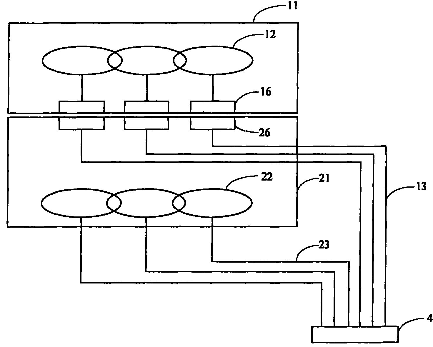
本发明中,为方便描述,将分离式线圈的两部分(上、下两部分或左、右两部分或其它形状的两部分)分别称为第一部分线圈和第二部分线圈,并相应地将第一部分线圈所在的线圈壳体称为第一部分壳体,将第二部分线圈所在的线圈壳体称为第二部分壳体。图1a为现有技术中一种分离式线圈的结构示意图,如图1a所示,分离式线圈包括位于第一部分壳体11中的第一部分线圈12和位于第二部分壳体21中的第二部分线圈22。其中,第二部分线圈22通过设置在第二部分壳体21中的第二电缆23与用于接入成像系统的接头24相连。图1a中,假设分离式线圈中的第一部分线圈12和第二部分线圈22分别包括三个线圈单元,且每个线圈单元对应一根电缆。当分离式线圈的第一部分线圈12和第二部分线圈22共同使用时,为了使第一部分线圈12的信号也能够正确输出,图1a中,在第一部分壳体11中设置第一部分线圈12的第一电缆13,并将第一电缆13和用于接入成像系统的接头14相连,其中,第一部分线圈12的三个线圈单元分别从第一部分壳体11中引出一根电缆13,引出的电缆13与接头14相连,通过电缆13和接头14将第一部分线圈12的信号输出给成像系统进行成像。该方法中,由于第一部分线圈12的电缆13和接头14需要占用额外的空间,因此使用时很不方便。In the present invention, for the convenience of description, the two parts of the separated coil (upper and lower parts or left and right parts or two parts of other shapes) are respectively referred to as the first part coil and the second part coil, and correspondingly The coil housing in which the first partial coil is located is referred to as the first partial housing, and the coil housing in which the second partial coil is located is referred to as the second partial housing. Figure 1a is a schematic structural view of a separate coil in the prior art. As shown in Figure 1a, the separate coil includes a first
图1b为现有技术中又一种分离式线圈的结构示意图,图1b中,将第一部分线圈12的电缆13和接头14设在第二部分壳体21中,并将第一部分线圈12的信号通过金属片连接至位于第二部分壳体21中的电缆13和接头14上,如图1b所示,金属片实际上也分为上、下两部分,金属片第一部分15和金属片第二部分25,其中,金属片第一部分15位于第一部分壳体11中,并与第一部分线圈12相连,金属片第二部分25位于第二部分壳体21中,并通过位于第二部分壳体21中的电缆13与接头14相连,其中,与金属片25相连的接头24和与第二部分线圈22相连的接头24可以并排设置在一起,如图1b中的接头4。但该方法中,随着线圈使用时间的推移,金属片表面会发生锈蚀或污染,从而造成电气的接触不良,此外,当单独使用第二部分线圈22时,未封闭的金属片第二部分25也会对病人造成一定的安全隐患。Fig. 1b is a structural schematic diagram of another separate coil in the prior art. In Fig. 1b, the
发明内容Contents of the invention
为了解决以上问题,本发明提供了一种可保证电气连接的可靠性的磁共振成像系统的分离式线圈。In order to solve the above problems, the present invention provides a separate coil for a magnetic resonance imaging system that can ensure the reliability of the electrical connection.
本发明所提供的磁共振成像系统的分离式线圈,包括:位于第一部分壳体中的第一部分线圈和位于第二部分壳体中的第二部分线圈,所述第一部分线圈和第二部分线圈分别通过第一电缆和第二电缆与用于接入成像系统的接头相连,The separate coil of the magnetic resonance imaging system provided by the present invention includes: a first partial coil located in the first partial housing and a second partial coil located in the second partial housing, the first partial coil and the second partial coil connected to the connector for accessing the imaging system through the first cable and the second cable respectively,
此外,该分离式线圈还包括耦合器,所述耦合器包括相互耦合的第一部分和第二部分,其中所述耦合器的第一部分设置在第一部分壳体中,并与所述第一部分线圈相连,所述耦合器的第二部分设置在第二部分壳体中,所述第一电缆设置在第二部分壳体中,所述耦合器的第二部分通过所述第一电缆与所述用于接入成像系统的接头相连。In addition, the split coil also includes a coupler, the coupler includes a first part and a second part coupled to each other, wherein the first part of the coupler is arranged in the first part housing and connected to the first part coil , the second part of the coupler is arranged in the second part housing, the first cable is arranged in the second part housing, the second part of the coupler passes through the first cable and the user Connect to the connector of the imaging system.
较佳地,所述第一部分线圈包括至少一个线圈单元,且每个线圈单元对应一个耦合器。Preferably, the first partial coil includes at least one coil unit, and each coil unit corresponds to a coupler.
较佳地,所述耦合器为电感耦合器。Preferably, the coupler is an inductive coupler.
较佳地,所述第一部分线圈的每个线圈单元与耦合器的等效电路包括:线圈单元电感、用于调节线圈单元性能指标的电容组件、耦合器相互耦合的两部分电感、线圈单元的失谐回路以及放大器;Preferably, the equivalent circuit of each coil unit of the first part of the coil and the coupler includes: coil unit inductance, a capacitive component for adjusting the performance index of the coil unit, two parts of inductance coupled by the coupler, coil unit Detuned loops and amplifiers;
其中,所述电容组件的一侧与所述线圈单元电感两连,所述电容组件的另一侧与耦合器相互耦合的第一部分电感相连,所述失谐回路的一侧与耦合器相互耦合的第二部分电感相连,所述失谐回路的另一侧与所述放大器相连,放大器的另一侧用于与第一电缆相连。Wherein, one side of the capacitive component is connected to the inductor of the coil unit twice, the other side of the capacitive component is connected to the first part of the inductance coupled with the coupler, and one side of the detuned circuit is coupled to the coupler The second part of the inductance is connected, the other side of the detuning loop is connected to the amplifier, and the other side of the amplifier is used to connect to the first cable.
其中,所述线圈单元电感、用于调节线圈单元性能指标的电容组件和耦合器相互耦合的第一部分电感设置在第一部分壳体中,所述耦合器相互耦合的第二部分电感、失谐回路以及放大器设置在第二部分壳体中。Wherein, the coil unit inductance, the capacitive component for adjusting the performance index of the coil unit, and the first part of the inductance coupled with each other by the coupler are arranged in the first part of the casing, and the second part of the inductance coupled by the coupler, the detuned loop And the amplifier is arranged in the second part housing.
较佳地,所述耦合器相互耦合的第一部分和第二部分的形状为蝴蝶状。Preferably, the first part and the second part of the coupler coupled with each other are butterfly-shaped.
较佳地,所述分离式线圈为头线圈或膝盖线圈。Preferably, the separate coil is a head coil or a knee coil.
从上述方案可以看出,本发明中,通过将用于输出第一部分线圈信号的第一电缆设置在第二部分壳体中,并在第一部分壳体和第二部分壳体之中设置耦合器,将耦合器的第一部分与第一部分线圈相连,将耦合器的第二部分通过设置在第二部分壳体中的第一电缆和用于接入成像系统的接头相连,使第一部分线圈的信号通过耦合器耦合连接至设置在第二部分壳体中的第一电缆和接头上,避免了金属连接带来的电气接触不良和安全隐患。It can be seen from the above scheme that in the present invention, by arranging the first cable for outputting the first part of the coil signal in the second part of the housing, and setting the coupler between the first part of the housing and the second part of the housing , connect the first part of the coupler to the first part of the coil, connect the second part of the coupler to the connector for accessing the imaging system through the first cable set in the second part housing, and make the signal of the first part of the coil The coupler is coupled and connected to the first cable and the connector provided in the second part of the housing, avoiding poor electrical contact and potential safety hazards caused by metal connections.
附图说明Description of drawings
下面将通过参照附图详细描述本发明的示例性实施例,使本领域的普通技术人员更清楚本发明的上述及其他特征和优点,附图中:Exemplary embodiments of the present invention will be described in detail below with reference to the accompanying drawings, so that those of ordinary skill in the art will be more aware of the above-mentioned and other features and advantages of the present invention. In the accompanying drawings:
图1a和图1b为现有技术中两种分离式线圈的结构示意图;Figure 1a and Figure 1b are structural schematic diagrams of two separate coils in the prior art;
图2为本发明实施例中分离式线圈的结构示意图;Fig. 2 is a schematic structural diagram of a separate coil in an embodiment of the present invention;
图3为本发明实施例中头线圈的耦合器布置示意图;Fig. 3 is a schematic diagram of the coupler layout of the head coil in the embodiment of the present invention;
图4a至图4d为本发明实施例中线圈耦合器的参数设计流程图。4a to 4d are flow charts of parameter design of the coil coupler in the embodiment of the present invention.
具体实施方式Detailed ways
为使本发明的目的、技术方案及优点更加清楚明白,以下参照附图并举实施例,对本发明进一步详细说明。In order to make the object, technical solution and advantages of the present invention clearer, the present invention will be further described in detail below with reference to the accompanying drawings and examples.
参见图2,图2为本发明实施例中分离式线圈的结构示意图。本发明实施例中,为了避免金属连接带来的电气不良和安全隐患,可将第一部分线圈12的信号通过耦合器耦合连接至位于第二部分壳体21中的第一电缆13和用于接入系统的接头4上。具体实现时,可将耦合器相互耦合的两部分分别设置在第一部分壳体11和第二部分壳体21内,为方便描述,可将耦合器相合耦合的两部分分别称为第一部分16和第二部分26,则耦合器的第一部分16可设置在第一部分壳体11中,并与第一部分线圈12相连,耦合器的第二部分26设置在第二部分壳体21中,并通过设置在第二部分壳体21中的第一电缆13和用于接入成像系统的接头4相连。这样的话,当线圈的两部分一起使用时,第一部分线圈12的信号可通过耦合器传输到位于第二部分壳体21中的第一电缆13和接头4,最后进入系统中进行成像,避免了两部分间金属连接带来的电气不良和安全隐患。Referring to FIG. 2, FIG. 2 is a schematic structural diagram of a separate coil in an embodiment of the present invention. In the embodiment of the present invention, in order to avoid electrical failure and potential safety hazards caused by the metal connection, the signal of the first part of the
通常情况下,第一部分线圈12和第二部分线圈22分别包括至少一个线圈单元,则第一部分线圈12的一个线圈单元对应一个耦合器。Usually, the first
其中,耦合器在放置时,可采用均匀放置,并且试验证明,为了有效减少耦合器与线圈单元之间的耦合效应,可采用蝴蝶状的耦合器,即耦合器的第一部分16和第二部分26的形状均为蝴蝶状。特别以头线圈为例,假设头线圈的第一部分线圈12包括三个线圈单元,则对于头线圈的第一部分壳体11的仰视视角而言,可设置如图3所示的均匀分布的三个蝴蝶状的耦合器的第一部分16,同样,对于头线圈第二部分壳体21的俯视视角而言,同样可得到与图3所示均匀分布的三个蝴蝶状的耦合器的第一部分16相对应的均匀分布的三个蝴蝶状的耦合器的第二部分26。其中,一个线圈单元对应一个耦合器。Among them, when the coupler is placed, it can be placed uniformly, and experiments have proved that in order to effectively reduce the coupling effect between the coupler and the coil unit, a butterfly-shaped coupler can be used, that is, the
本实施例中,耦合器可以是电感耦合器,也可以是电容耦合器等。以电感耦合器为例,为了使耦合器的参数满足信噪比损耗需求,可预先确定耦合器的相关参数,包括耦合系数Km,等效阻抗Xm等,根据确定的耦合器的相关参数确定满足信噪比损耗需求的耦合器。In this embodiment, the coupler may be an inductive coupler, or a capacitive coupler or the like. Taking the inductive coupler as an example, in order to make the parameters of the coupler meet the SNR loss requirement, the relevant parameters of the coupler can be determined in advance, including coupling coefficient Km, equivalent impedance Xm, etc. coupler for signal-to-noise ratio loss requirements.
图4a至图4d为本发明实施例中线圈耦合器的参数设计流程图。如图4a所示,图4a为本发明实施例中带电感耦合器的第一部分线圈一个线圈单元的电路示意图。其中,每个线圈单元与耦合器的等效电路包括:线圈单元电感、用于调节线圈单元性能指标的电容组件、耦合器相互耦合的两部分电感、线圈单元的失谐回路以及放大器。其中,电容组件的一侧与线圈单元电感两连,另一侧与耦合器相互耦合的一部分电感相连;失谐回路的一侧与耦合器相互耦合的另一部分电感相连,另一侧与放大器相连,放大器的另一侧用于与第一电缆13相连。4a to 4d are flow charts of parameter design of the coil coupler in the embodiment of the present invention. As shown in FIG. 4a, FIG. 4a is a schematic circuit diagram of a coil unit of the first partial coil with an inductive coupler in an embodiment of the present invention. Wherein, the equivalent circuit of each coil unit and coupler includes: coil unit inductance, capacitive component for adjusting the performance index of coil unit, two parts of inductance coupled by coupler, detuning circuit of coil unit and amplifier. Among them, one side of the capacitor component is connected to the inductance of the coil unit, and the other side is connected to a part of the inductance coupled with the coupler; one side of the detuned circuit is connected to the other part of the inductance coupled to the coupler, and the other side is connected to the amplifier. , the other side of the amplifier is used to connect with the
图4a中,电感L1为线圈单元电感;两个电容C11、一个电容C12、两个电容C22为工字形的电容组件,其中,两个电容C11用于调试线圈单元的频率,电容C12用于调试线圈单元的匹配,两个电容C22用于调试线圈单元的相位;电感L2、L3为耦合器相互耦合的两部分电感,电容C3、电感L4和二极管D1为所述线圈单元的失谐回路;失谐回路后面的放大器(Amp)用于对信号进行预放大处理,放大后的信号通过电缆13输出。In Figure 4a, the inductance L1 is the inductance of the coil unit; two capacitors C11, one capacitor C12, and two capacitors C22 are I-shaped capacitor components, where the two capacitors C11 are used to debug the frequency of the coil unit, and the capacitor C12 is used for debugging For the matching of the coil unit, two capacitors C22 are used to adjust the phase of the coil unit; the inductance L2 and L3 are two parts of the inductance coupled by the coupler, and the capacitor C3, the inductance L4 and the diode D1 are the detuning circuit of the coil unit; The amplifier (Amp) behind the harmonic circuit is used to pre-amplify the signal, and the amplified signal is output through the
其中,各元件的连接关系为:电容C12的一端与一个电容C11的一端、一个电容C22的一端相连,电容C12的另一端与另一个电容C11的一端、另一个电容C22的一端相连,两个电容C11的另一端分别与电感L1的两端相连,两个电容C22的另一端分别与电感L2的两端相连;电感L2和电感L3耦合连接;电感L3的一端与电容C3的一端、电感L4的一端相连,电感L3的另一端与电容C3的另一端、二级管D1的一端、放大器的一个输入端、以及地相连,电感L4的另一端与二级管D1的另一端、放大器的一个输入端相连。Among them, the connection relationship of each element is: one end of the capacitor C12 is connected with one end of a capacitor C11 and one end of a capacitor C22, the other end of the capacitor C12 is connected with one end of another capacitor C11, and one end of another capacitor C22. The other ends of the capacitor C11 are respectively connected to the two ends of the inductor L1, and the other ends of the two capacitors C22 are respectively connected to the two ends of the inductor L2; the inductor L2 and the inductor L3 are coupled and connected; one end of the inductor L3 is connected to one end of the capacitor C3, the inductor L4 One end of the inductor L3 is connected to the other end of the capacitor C3, one end of the diode D1, one input end of the amplifier, and the ground, and the other end of the inductor L4 is connected to the other end of the diode D1, one of the amplifier connected to the input.
图4a中,L2及其左边部分的电路设置在第一部分壳体11中,L3及其右边部分的电路设置在第二部分壳体21中。In FIG. 4 a , L2 and the circuit on its left side are arranged in the
基于图4a所示的电路图,为了便于运算,可将图4a所示电路图等效为图4b所示电路图,其中,将病人的阻抗Rp考虑进来,并且将电感L1等效为纯电感L1和阻抗RL1;将由两个C11、两个C22和一个C12组成的工字形电路等效为由一个C1、一个C2和一个C12组成的T字形电路;将电感L2等效为纯电感L2和阻抗R2,电感L3等效为纯电感L3和阻抗R3,并且将图4a所示电感L2、L3组成的耦合器等效为图4b所示的T字形的耦合器,其中,T字形的耦合器中的Lm为耦合器因为耦合而产生的等效电感;此外,将电感L4等效为纯电感L4和阻抗R4。Based on the circuit diagram shown in Figure 4a, for the convenience of calculation, the circuit diagram shown in Figure 4a can be equivalent to the circuit diagram shown in Figure 4b, where the patient's impedance Rp is taken into account, and the inductance L1 is equivalent to pure inductance L1 and impedance RL1; the I-shaped circuit composed of two C11, two C22 and one C12 is equivalent to a T-shaped circuit composed of one C1, one C2 and one C12; the inductance L2 is equivalent to a pure inductance L2 and impedance R2, the inductance L3 is equivalent to pure inductance L3 and impedance R3, and the coupler composed of inductance L2 and L3 shown in Figure 4a is equivalent to the T-shaped coupler shown in Figure 4b, where Lm in the T-shaped coupler is The equivalent inductance of the coupler due to coupling; in addition, the inductance L4 is equivalent to a pure inductance L4 and an impedance R4.
进一步地,为了方便计算,可对图4b进行简化,并得到如图4c所示简化后的电路图,其中JX1为电感L1的感抗;-JX1为电容C1的容抗;两个感抗JX12和容抗-JX12组成的90度的T型移相器;-JX12为电容C2的容抗;JX2为电感L2的感抗;两个容抗-JXm和感抗JXm组成的-90度的T型移相器;JX3为电感L3的感抗,JX3也为电感L4的感抗,-JX3为电容C3的容抗,且两个JX3和-JX3组成90度的T型移相器。Further, for the convenience of calculation, Fig. 4b can be simplified, and a simplified circuit diagram as shown in Fig. 4c can be obtained, wherein JX1 is the inductance of the inductor L1; -JX1 is the capacitive reactance of the capacitor C1; two inductances JX12 and Capacitive reactance-JX12 is composed of 90-degree T-type phase shifter; -JX12 is the capacitive reactance of capacitor C2; JX2 is the inductive reactance of inductor L2; two capacitive reactance-JXm and inductive reactance JXm are composed of -90-degree T-shaped Phase shifter; JX3 is the inductive reactance of the inductor L3, JX3 is also the inductive reactance of the inductor L4, -JX3 is the capacitive reactance of the capacitor C3, and two JX3 and -JX3 form a 90-degree T-shaped phase shifter.
进一步地,将图4c所示电路图中绝对值相同的正负项相互抵消后,得到简化后的图4d所示的电路图,图4d中,R1代表RL1和Rp之和;X12代表两个感抗JX12和容抗-JX12组成的90度的T型移相器;Xm代表两个容抗-JXm和感抗JXm组成的-90度的T型移相器;X3代表两个JX3和-JX3组成90度的T型移相器。其中,图4b至图4d中的R2、R3和R4均相同。Further, after canceling the positive and negative items with the same absolute value in the circuit diagram shown in Figure 4c, the simplified circuit diagram shown in Figure 4d is obtained. In Figure 4d, R1 represents the sum of RL1 and Rp; X12 represents two inductive reactances A 90-degree T-type phase shifter composed of JX12 and capacitive reactance-JX12; Xm represents a -90-degree T-type phase shifter composed of two capacitive reactance-JXm and inductive reactance JXm; X3 represents two JX3 and -JX3 components 90 degree T-type phase shifter. Wherein, R2, R3 and R4 in Fig. 4b to Fig. 4d are all the same.
通过对上述图4a至图4d所示电路图的分析及计算,可得到如下公式:Through the analysis and calculation of the circuit diagrams shown in Figure 4a to Figure 4d above, the following formula can be obtained:

其中,
之后,根据Km的取值及Km与耦合等效电感Lm的关系式
根据Lm的取值及线圈的工作频率ω,计算得到耦合器的等效阻抗Xm,即Xm=Lm·ω。According to the value of Lm and the operating frequency ω of the coil, the equivalent impedance Xm of the coupler is calculated, that is, Xm=Lm·ω.
从而最终确定出耦合器两部分的电感参数。Thus finally determine the inductance parameters of the two parts of the coupler.
在确定出上述参数后,为了保障能够满足应用需求,可进一步根据Xm的取值,对第一部分线圈一个线圈单元的由两个感抗JX12和容抗-JX12组成的90度的T型移相器的等效阻抗进行调整,如下式所示:After the above parameters are determined, in order to ensure that the application requirements can be met, further according to the value of Xm, the 90-degree T-type phase shift composed of two inductive reactance JX12 and capacitive reactance-JX12 of the first part of the coil and one coil unit The equivalent impedance of the device is adjusted, as shown in the following formula:
通过计算可得到X12的取值。The value of X12 can be obtained by calculation.
以上所述仅为本发明的较佳实施例而已,并非用于限定本发明的保护范围。凡在本发明的精神和原则之内,所作的任何修改、等同替换以及改进等,均应包含在本发明的保护范围之内。The above descriptions are only preferred embodiments of the present invention, and are not intended to limit the protection scope of the present invention. Any modifications, equivalent replacements and improvements made within the spirit and principles of the present invention shall be included within the protection scope of the present invention.
Claims (5)
Priority Applications (2)
| Application Number | Priority Date | Filing Date | Title |
|---|---|---|---|
| CN2008100052049A CN101498771B (en) | 2008-01-29 | 2008-01-29 | Separation type coil of magnetic resonance imaging system |
| US12/361,716 US8030930B2 (en) | 2008-01-29 | 2009-01-29 | Magnetic resonance imaging local coil composed of separate parts |
Applications Claiming Priority (1)
| Application Number | Priority Date | Filing Date | Title |
|---|---|---|---|
| CN2008100052049A CN101498771B (en) | 2008-01-29 | 2008-01-29 | Separation type coil of magnetic resonance imaging system |
Publications (2)
| Publication Number | Publication Date |
|---|---|
| CN101498771A CN101498771A (en) | 2009-08-05 |
| CN101498771B true CN101498771B (en) | 2011-12-07 |
Family
ID=40898564
Family Applications (1)
| Application Number | Title | Priority Date | Filing Date |
|---|---|---|---|
| CN2008100052049A Expired - Fee Related CN101498771B (en) | 2008-01-29 | 2008-01-29 | Separation type coil of magnetic resonance imaging system |
Country Status (2)
| Country | Link |
|---|---|
| US (1) | US8030930B2 (en) |
| CN (1) | CN101498771B (en) |
Families Citing this family (7)
| Publication number | Priority date | Publication date | Assignee | Title |
|---|---|---|---|---|
| JP5248557B2 (en) * | 2010-07-29 | 2013-07-31 | ジーイー・メディカル・システムズ・グローバル・テクノロジー・カンパニー・エルエルシー | Magnetic resonance imaging system |
| WO2014177975A1 (en) * | 2013-05-02 | 2014-11-06 | Koninklijke Philips N.V. | A detachable connector and splittable rf coil housings |
| US10353026B2 (en) * | 2015-06-15 | 2019-07-16 | Siemens Aktiengesellschaft | MRI coil for use during an interventional procedure |
| JP6687375B2 (en) * | 2015-11-30 | 2020-04-22 | キヤノンメディカルシステムズ株式会社 | RF coil and magnetic resonance imaging apparatus |
| KR101806198B1 (en) * | 2016-12-30 | 2017-12-08 | 연세대학교 산학협력단 | Radiofrequency coil and medicla imaging apparatus using the same |
| CN108519570A (en) * | 2018-05-10 | 2018-09-11 | 达研医疗技术(合肥)有限公司 | A kind of wearable magnetic resonance coil based on nano material |
| US11280859B2 (en) * | 2018-05-31 | 2022-03-22 | General Electric Company | Method and systems for a radio frequency coil assembly |
Citations (5)
| Publication number | Priority date | Publication date | Assignee | Title |
|---|---|---|---|---|
| US5489847A (en) * | 1993-06-08 | 1996-02-06 | Hitachi, Ltd. | RF probe for MRI |
| US5664568A (en) * | 1995-08-08 | 1997-09-09 | Picker International, Inc. | Split-top, neck and head vascular array for magnetic resonance imaging |
| US6501274B1 (en) * | 1999-10-15 | 2002-12-31 | Nova Medical, Inc. | Magnetic resonance imaging system using coils having paraxially distributed transmission line elements with outer and inner conductors |
| US6577888B1 (en) * | 2000-09-29 | 2003-06-10 | Usa Instruments, Inc. | Sliding-dome and split-top MRI radio frequency quadrature array coil system |
| US6784665B1 (en) * | 2001-11-19 | 2004-08-31 | General Electric Company | Multiple degree of freedom adjustable MRI radio frequency array coil system |
Family Cites Families (3)
| Publication number | Priority date | Publication date | Assignee | Title |
|---|---|---|---|---|
| US7215120B2 (en) * | 2002-05-17 | 2007-05-08 | Mr Instruments, Inc. | Cavity resonator for MR systems |
| CN100578250C (en) * | 2003-11-18 | 2010-01-06 | 皇家飞利浦电子股份有限公司 | Hybrid TEM/Birdcage Coils for MRI |
| US7659719B2 (en) * | 2005-11-25 | 2010-02-09 | Mr Instruments, Inc. | Cavity resonator for magnetic resonance systems |
-
2008
- 2008-01-29 CN CN2008100052049A patent/CN101498771B/en not_active Expired - Fee Related
-
2009
- 2009-01-29 US US12/361,716 patent/US8030930B2/en not_active Expired - Fee Related
Patent Citations (5)
| Publication number | Priority date | Publication date | Assignee | Title |
|---|---|---|---|---|
| US5489847A (en) * | 1993-06-08 | 1996-02-06 | Hitachi, Ltd. | RF probe for MRI |
| US5664568A (en) * | 1995-08-08 | 1997-09-09 | Picker International, Inc. | Split-top, neck and head vascular array for magnetic resonance imaging |
| US6501274B1 (en) * | 1999-10-15 | 2002-12-31 | Nova Medical, Inc. | Magnetic resonance imaging system using coils having paraxially distributed transmission line elements with outer and inner conductors |
| US6577888B1 (en) * | 2000-09-29 | 2003-06-10 | Usa Instruments, Inc. | Sliding-dome and split-top MRI radio frequency quadrature array coil system |
| US6784665B1 (en) * | 2001-11-19 | 2004-08-31 | General Electric Company | Multiple degree of freedom adjustable MRI radio frequency array coil system |
Also Published As
| Publication number | Publication date |
|---|---|
| CN101498771A (en) | 2009-08-05 |
| US20090189610A1 (en) | 2009-07-30 |
| US8030930B2 (en) | 2011-10-04 |
Similar Documents
| Publication | Publication Date | Title |
|---|---|---|
| CN101498771B (en) | Separation type coil of magnetic resonance imaging system | |
| CN104916894B (en) | Directional coupler | |
| JP6172479B2 (en) | Directional coupler | |
| JP2012070279A5 (en) | Signal transmission circuit, transmission device and circuit board | |
| CN109120307B (en) | Power line carrier communication system and band-pass matching coupler thereof | |
| EP2757686B1 (en) | Filter circuit | |
| CN102237900B (en) | Communication device and communication system | |
| CN103412271A (en) | Multi-channel nuclear magnetic resonance coil | |
| CN101326678B (en) | Balance-unbalance converter and electronic device using this | |
| Ganz | A simple, exact equivalent circuit for the three-winding transformer | |
| CN210572692U (en) | Feed-through filter applied to magnetic resonance system and magnetic resonance system | |
| US20050043612A1 (en) | Multipurpose connection/reception device for nuclear magnetic resonance imager | |
| JP4708068B2 (en) | Power line communication system | |
| JP2007142931A (en) | Noise filter | |
| JP6085689B2 (en) | Circuit equipment | |
| CN111987398A (en) | Super Capacitive Coupling Structure | |
| CN101086525B (en) | Inductively coupled receiving coil | |
| JPH0722251B2 (en) | Coupling device | |
| CN103715993A (en) | Low-frequency voltage-controlled phase-shift circuit | |
| CN222814453U (en) | Single-phase filter structure | |
| JP2004356918A (en) | Noise suppression circuit | |
| US8217657B2 (en) | Diplex filter and method to filter signals | |
| JP4735087B2 (en) | 90 degree hybrid circuit and Wilkinson power distribution circuit | |
| JP2005005881A (en) | Balancing circuit for communication line, and power line communication circuit | |
| CN115425934B (en) | Output matching circuit of power amplifier |
Legal Events
| Date | Code | Title | Description |
|---|---|---|---|
| C06 | Publication | ||
| PB01 | Publication | ||
| C10 | Entry into substantive examination | ||
| SE01 | Entry into force of request for substantive examination | ||
| C14 | Grant of patent or utility model | ||
| GR01 | Patent grant | ||
| TR01 | Transfer of patent right | ||
| TR01 | Transfer of patent right |
Effective date of registration: 20210114 Address after: Room 516, 5th floor, 38 Yinglun Road, China (Shanghai) pilot Free Trade Zone, Pudong New Area, Shanghai 200031 Patentee after: SIEMENS HEALTHCARE Ltd. Address before: 100102 No. 7 South Central Road, Chaoyang District, Beijing, China Patentee before: SIEMENS Ltd. CHINA |
|
| CF01 | Termination of patent right due to non-payment of annual fee | ||
| CF01 | Termination of patent right due to non-payment of annual fee |
Granted publication date: 20111207 |