CN101497271B - Ink Supply Cartridges Containing Ink Shutoff Elements - Google Patents
Ink Supply Cartridges Containing Ink Shutoff Elements Download PDFInfo
- Publication number
- CN101497271B CN101497271B CN200810005788XA CN200810005788A CN101497271B CN 101497271 B CN101497271 B CN 101497271B CN 200810005788X A CN200810005788X A CN 200810005788XA CN 200810005788 A CN200810005788 A CN 200810005788A CN 101497271 B CN101497271 B CN 101497271B
- Authority
- CN
- China
- Prior art keywords
- ink
- ink supply
- side wall
- guide post
- supply box
- Prior art date
- Legal status (The legal status is an assumption and is not a legal conclusion. Google has not performed a legal analysis and makes no representation as to the accuracy of the status listed.)
- Expired - Fee Related
Links
- 238000003780 insertion Methods 0.000 claims abstract description 25
- 230000037431 insertion Effects 0.000 claims abstract description 25
- 238000002955 isolation Methods 0.000 claims description 22
- 238000007789 sealing Methods 0.000 claims description 10
- 238000011084 recovery Methods 0.000 claims description 5
- 238000010586 diagram Methods 0.000 description 9
- 239000000463 material Substances 0.000 description 5
- 230000000694 effects Effects 0.000 description 3
- 238000010304 firing Methods 0.000 description 3
- 238000005192 partition Methods 0.000 description 3
- 229920001296 polysiloxane Polymers 0.000 description 2
- 238000007639 printing Methods 0.000 description 2
- 239000013013 elastic material Substances 0.000 description 1
- 230000008676 import Effects 0.000 description 1
- 238000009434 installation Methods 0.000 description 1
- 239000007788 liquid Substances 0.000 description 1
- 238000000034 method Methods 0.000 description 1
- 229920002050 silicone resin Polymers 0.000 description 1
Images


Landscapes
- Ink Jet (AREA)
Abstract
Description
技术领域technical field
本发明有关一种供墨匣,尤指一种适用于连续供墨系统的供墨匣,以输出墨水至打印机的墨水匣,并同时避免置换供墨匣时有漏墨的情形产生。The present invention relates to an ink supply cartridge, especially an ink supply cartridge suitable for a continuous ink supply system to output ink to the ink cartridge of a printer, while avoiding ink leakage when replacing the ink supply cartridge.
背景技术Background technique
随着电脑日渐普及,以打印机打印出文件的需求也日益增加,而喷墨打印机是目前最受大众接受的打印机之一。由于喷墨打印机墨水匣售价昂贵且墨水含量亦有所限制,因此已发展出连续供墨系统以解决打印成本的问题。With the increasing popularity of computers, the demand for printing out documents by printers is also increasing, and inkjet printers are currently one of the most popular printers. Since the ink cartridges of inkjet printers are expensive and the ink content is limited, a continuous ink supply system has been developed to solve the printing cost problem.
传统的连续供墨系统是利用虹吸作用将供墨匣内的墨水导入到打印机的墨水匣中。其中,供墨匣设置高度一般是与打印机在同一平面上,且供墨匣内的墨水液面要略低于打印机喷嘴。同时,由于供墨匣是设置于打印机的外部,故必须利用管线将供墨匣与打印机连接,反而造成外部管线缠绕而影响美观。The traditional continuous ink supply system uses siphon action to import the ink in the ink cartridge into the ink cartridge of the printer. Wherein, the installation height of the ink supply box is generally on the same plane as the printer, and the liquid level of the ink in the ink supply box is slightly lower than the nozzle of the printer. At the same time, since the ink supply cartridge is arranged outside the printer, pipelines must be used to connect the ink supply cartridge to the printer, which will cause external pipelines to be entangled and affect the appearance.
因此,已发展出一种具有供墨匣承载架的连续供墨系统,其可同时安装一个或多个供墨匣,而能稳定的将墨水输出至打印机的墨水匣。Therefore, a continuous ink supply system with an ink cartridge carrier has been developed, which can install one or more ink cartridges at the same time, and can output ink to the ink cartridge of the printer stably.
如图1所示,此为已知的连续供墨系统的示意图,其显示供墨匣与供墨匣承载架的结构。一般而言,供墨匣12具有一壳体121,于壳体121内部填充有墨水;同时于供墨匣12的上方设置有一进气口(图中未示)以将外界空气导入供墨匣12中来产生负压(back pressure),且通过负压的推动,可将墨水引出至供墨匣12外部。另一方面,供墨匣承载架11包含多个供墨匣隔间111,以提供多个可置换的供墨匣12容置于其中。供墨匣隔间111内壁其相对面的两间隔壁112上分别设置有凸缘1121,此凸缘1121的位置是配对于设置在供墨匣12侧面的凹槽1211。因此,使用者可通过凹槽1211与凸缘1121的相互滑动,将供墨匣12进入或退出供墨匣隔间111中。As shown in FIG. 1 , which is a schematic diagram of a known continuous ink supply system, it shows the structure of the ink supply cartridge and the ink supply cartridge carrier. Generally speaking, the
接着,如图2所示,此为上连续供墨系统的正视图,此为供墨匣设置于供墨匣承载架上的正视图。当供墨匣12设置于供墨匣承载架11的一供墨匣隔间111后,通过供墨匣12的凹槽1211与供墨匣承载架11的凸缘1121,并将供墨匣12卡合于供墨匣承载架11上。Next, as shown in FIG. 2 , this is the front view of the upper continuous ink supply system, and this is the front view of the ink supply cartridge set on the ink supply cartridge carrier. After the
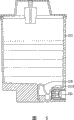
图3为已知的供墨匣剖面图。此供墨匣12的壳体121的一侧壁1212上设置有一顶柱122,且顶柱122是容置于由侧壁1212与一墨水出口部124所形成的容置空间125中。如图2及图3所示,当将供墨匣12设置于供墨匣承载架11时,供墨匣承载架11上的插针113可将供墨匣12的隔离膜1241刺破,使墨水能引出供墨匣12外部,以输出墨水至打印机的墨水匣(图中未示)。Figure 3 is a sectional view of a known ink supply cartridge. A
然而,当要置换供墨匣12而将供墨匣12抽离供墨匣承载架11时,墨水出口部124的隔离膜1241受到压力的影响,虽然能让供墨匣12内的墨水不致于大量外漏,但仍会有些许漏墨的情形发生。另一方面,若插针113刺破隔离膜1241所造成的开孔过大,则可能造成严重的漏墨情形。因此,必须要发展出一种供墨匣,其可避免在抽离供墨匣时所产生的漏墨情形。However, when the
发明内容Contents of the invention
本发明的主要目的是提供一种供墨匣,其具有一断墨组件,以能在置换此供墨匣时减少或抑制漏墨。The main purpose of the present invention is to provide an ink supply box with an ink cut-off assembly, so as to reduce or suppress ink leakage when the ink supply box is replaced.
本发明的另一目的是提供一种连续供墨系统,其具有一供墨匣承载架,可供多个供墨匣固定安装于其上,以连续供墨至打印机的墨水匣中。Another object of the present invention is to provide a continuous ink supply system, which has an ink supply cartridge carrier, on which a plurality of ink supply cartridges can be fixedly mounted to continuously supply ink to the ink cartridges of the printer.
为达成上述目的,本发明提供一种供墨匣,其包括:一壳体以及一断墨组件。其中,此壳体包含一顶柱,顶柱设置该壳体的一侧壁并自该壳体的该侧壁延伸,且侧壁具有至少一插孔。此外,此断墨组件设置于壳体中,且断墨组件包含一基座、一弹性组件、以及至少一导柱。弹性组件以及至少一导柱是分别位于基座的两侧,而至少一导柱插置于相对应的至少一插孔中,且突出壳体的侧壁。To achieve the above purpose, the present invention provides an ink supply cartridge, which includes: a casing and an ink cutoff assembly. Wherein, the casing includes a top column, the top column is arranged on a side wall of the casing and extends from the side wall of the casing, and the side wall has at least one insertion hole. In addition, the ink break assembly is arranged in the casing, and the ink break assembly includes a base, an elastic component, and at least one guide column. The elastic component and the at least one guide post are respectively located on two sides of the base, and the at least one guide post is inserted into the corresponding at least one insertion hole and protrudes from the side wall of the casing.
另一方面,本发明亦提供一种连续供墨系统,其包括:一供墨匣以及一供墨匣承载架。此供墨匣包含:一壳体,以及一断墨组件。其中此壳体包含一顶柱,顶柱设置该壳体的一侧壁并自该壳体的该侧壁延伸,且侧壁具有至少一插孔。另外,断墨组件设置于壳体中,且断墨组件包含:一基座、一弹性组件、以及至少一导柱。弹性组件以及至少一导柱是分别位于基座的两侧,至少一导柱插置于相对应的至少一插孔中,且突出侧壁。另一方面,此供墨匣承载架包含:多个供墨匣隔间,以及多个插针。其中,供墨匣隔间用以容置供墨匣,且每一供墨匣隔间内设置一插针。此外,当供墨匣容置于供墨匣隔间时,插针顶住此至少一导柱。On the other hand, the present invention also provides a continuous ink supply system, which includes: an ink supply box and an ink supply box carrying frame. The ink supply box includes: a casing, and an ink cutoff assembly. Wherein the casing includes a top column, the top column is arranged on a side wall of the casing and extends from the side wall of the casing, and the side wall has at least one insertion hole. In addition, the ink break assembly is arranged in the casing, and the ink break assembly includes: a base, an elastic component, and at least one guide post. The elastic component and at least one guide column are respectively located on two sides of the base, and the at least one guide column is inserted into the corresponding at least one insertion hole and protrudes from the side wall. On the other hand, the ink supply cartridge carrier includes: a plurality of ink supply cartridge compartments, and a plurality of pins. Wherein, the compartment for the ink cartridge is used for accommodating the ink cartridge, and a pin is arranged in each compartment for the ink cartridge. In addition, when the ink supply cartridge is accommodated in the compartment of the ink supply cartridge, the insertion pin bears against the at least one guide post.
因此,本发明的供墨匣通过断墨组件的设计,在供墨匣未使用时,能抑制或完全阻隔墨水从顶柱排出。同时,于本发明的连续供墨系统中,当供墨匣设置于供墨匣承载架上时,通过设置供墨匣承载架上的插针,可顶住供墨匣的导柱,并进一步推移供墨匣的断墨组件,使得墨水能从顶柱内输出。再者,当供墨匣从供墨匣承载架上退出时,由于断墨组件具有弹性恢复力,因此断墨组件可恢复至未设置于供墨匣承载架上的状态,故能完全阻挡墨水从顶柱中漏出,进而防止漏墨的情形产生并达到断墨的效果。Therefore, the ink supply cartridge of the present invention can suppress or completely block the discharge of ink from the ejector post when the ink supply cartridge is not in use through the design of the ink breaker assembly. At the same time, in the continuous ink supply system of the present invention, when the ink supply box is arranged on the ink supply box carrier, the pins on the ink supply box carrier can be set to withstand the guide post of the ink supply box, and further Push the ink breaker assembly of the ink supply cartridge so that the ink can be output from the top post. Furthermore, when the ink supply box is withdrawn from the ink supply box carrier, because the ink breaker assembly has elastic recovery force, the ink breaker assembly can return to the state that it is not installed on the ink supply box support frame, so it can completely block the ink It leaks from the top column, thereby preventing the occurrence of ink leakage and achieving the effect of ink breaking.
另一方面,本发明的供墨匣其断墨组件,还可包括一密封组件,其设置于基座上并与至少一导柱位于基座的同一侧,且围绕至少一导柱。此外,此密封组件的材料并无限制,较佳为具有弹性的材料,更佳为橡胶。On the other hand, the ink cut-off component of the ink supply box of the present invention may further include a sealing component, which is disposed on the base and on the same side of the base as the at least one guide post, and surrounds the at least one guide post. In addition, the material of the sealing component is not limited, preferably elastic material, more preferably rubber.
本发明的供墨匣较佳可还包括一墨水出口部,该墨水出口部还包括两侧缘以及一隔离膜;其中隔离膜设置于两侧缘间,而两侧缘、隔离膜、以及壳体的侧壁围成一空间,以使顶柱以及至少一导柱突出侧壁的部分容置于空间中。此外,隔离膜的材料并无限制,较佳为能被插针轻易刺破的材质,更佳为硅树脂(silicone)。The ink supply cartridge of the present invention preferably further includes an ink outlet portion, and the ink outlet portion also includes two side edges and an isolation film; wherein the isolation film is arranged between the two side edges, and the two side edges, the isolation film, and the shell The side wall of the body encloses a space, so that the part of the top post and at least one guide post protruding from the side wall is accommodated in the space. In addition, the material of the isolation film is not limited, and it is preferably a material that can be easily pierced by a pin, more preferably silicone.
本发明的供墨匣还可包括一进气口,进气口设置于该供墨匣的上方。The ink supply box of the present invention can also include an air inlet, and the air inlet is arranged above the ink supply box.
本发明的供墨匣其弹性组件较佳可为一弹片。此外,此弹性组件的外形并无限制,较佳为一S形弹片。The elastic component of the ink supply cartridge of the present invention is preferably a shrapnel. In addition, the shape of the elastic component is not limited, and is preferably an S-shaped shrapnel.
本发明的供墨匣其断墨组件可包含两导柱。另外,供墨匣的顶柱可位于此两导柱之间。The ink breaker assembly of the ink supply cartridge of the present invention may include two guide posts. In addition, the top post of the ink supply cartridge can be located between the two guide posts.
于本发明的连续供墨系统的供墨匣承载架中,插针可包含:一撞针、以及一导墨组件;且导墨组件设置于撞针内部。此外,此插针还可包含一弹性恢复组件,此弹性恢复组件连接于导墨组件,且设置于撞针内部。另一方面,设置于撞针内部的导墨组件还可包含至少一流道。In the ink cartridge carrier of the continuous ink supply system of the present invention, the inserting pin may include: a firing pin and an ink guiding component; and the ink guiding component is arranged inside the firing pin. In addition, the insertion pin can also include an elastic recovery component, which is connected to the ink guiding component and arranged inside the striker. On the other hand, the ink guiding component disposed inside the striker can also include at least one channel.
除此之外,上述的撞针内径是大于顶柱的外径,使顶柱可插置于撞针内并连接导墨组件;且撞针的管壁厚度是大于顶柱与至少一导柱的距离,使本发明的插针通过此撞针顶住至少一导柱。In addition, the above-mentioned inner diameter of the striker is larger than the outer diameter of the ejector pin, so that the ejector pin can be inserted into the striker and connected to the ink guide assembly; and the wall thickness of the striker is greater than the distance between the ejector pin and at least one guide pin, Make the pin of the present invention bear against at least one guide post through the firing pin.
另一方面,本发明的连续供墨系统的供墨匣,其侧面还可含至少两凹槽。而本发明的连续供墨系统的供墨匣承载架,其供墨匣隔间的相对面间隔壁上还可包含至少两凸缘,且至少两凸缘配对于供墨匣的至少两凹槽,使供墨匣滑入供墨匣隔间并卡合固定于供墨匣隔间内。On the other hand, the side of the ink supply box of the continuous ink supply system of the present invention may further include at least two grooves. And the ink supply box carrier frame of the continuous ink supply system of the present invention can also comprise at least two flanges on the partition wall on the opposite surface of the ink supply box compartment, and at least two flanges are matched with at least two grooves of the ink supply box , so that the ink supply cartridge slides into the ink supply cartridge compartment and snaps and fixes in the ink supply cartridge compartment.
于本发明的连续供墨系统的供墨匣承载架中,其每一供墨匣隔间还可包含一卡榫,此卡榫位于供墨匣的下方。In the ink cartridge carrier of the continuous ink supply system of the present invention, each compartment of the ink cartridge can further include a tenon, and the tenon is located under the ink cartridge.
此外,于本发明的连续供墨系统的供墨匣承载架中,其每一供墨匣隔间上方还可包含一顶推弹片,当供墨匣从供墨匣承载架上退出时,此顶推弹片能提供一弹性恢复力,使供墨匣能轻易从供墨匣承载架上卸下。In addition, in the ink supply box carrier of the continuous ink supply system of the present invention, a push shrapnel can also be included above each ink supply box compartment, and when the ink supply box withdraws from the ink supply box carrier, this The push shrapnel can provide an elastic restoring force, so that the ink supply cartridge can be easily unloaded from the ink supply cartridge carrier.
附图说明Description of drawings
图1是已知的连续供墨系统的示意图。Figure 1 is a schematic diagram of a known continuous ink supply system.
图2是已知的连续供墨系统的正视图。Figure 2 is a front view of a known continuous ink supply system.
图3是已知的供墨匣剖面图。Figure 3 is a sectional view of a known ink supply cartridge.
图4是本发明一较佳实施例的连续供墨系统的示意图。Fig. 4 is a schematic diagram of a continuous ink supply system according to a preferred embodiment of the present invention.
图5是本发明一较佳实施例的供墨匣的剖面图。Fig. 5 is a sectional view of an ink supply cartridge according to a preferred embodiment of the present invention.
图6是本发明一较佳实施例的供墨匣的断墨组件的示意图。Fig. 6 is a schematic diagram of an ink cut-off assembly of an ink supply cartridge according to a preferred embodiment of the present invention.
图7是本发明一较佳实施例的连续供墨系统正视图。Fig. 7 is a front view of a continuous ink supply system according to a preferred embodiment of the present invention.
图8是本发明一较佳实施例的供墨匣设置于供墨匣承载架的剖面图。FIG. 8 is a cross-sectional view of an ink supply cartridge disposed on an ink supply cartridge carrier according to a preferred embodiment of the present invention.
图9是本发明一较佳实施例的Fig. 9 is a preferred embodiment of the present invention
图10是本发明一较佳实施例的墨水输出状态的示意图。Fig. 10 is a schematic diagram of the ink output state of a preferred embodiment of the present invention.
具体实施方式Detailed ways
如图4所示,此为本发明一较佳实施例的连续供墨系统的示意图。本发明的连续供墨系统包括一供墨匣承载架21以及一供墨匣22,其中供墨匣承载架21包含多个供墨匣隔间211,而供墨匣22则可设置于此供墨匣隔间211中。为了使供墨匣22能固定设置供墨匣承载架21上,于供墨匣22的侧面上还包含两凹槽2211,且供墨匣隔间211的相对面间隔壁212上还包含两凸缘2121。因此,可通过凹槽2211与凸缘2121的相互滑动,将将供墨匣22进入或退出供墨匣承载架21的供墨匣隔间211中。且由于凹槽2211与凸缘1121的设计,可将供墨匣22卡合于供墨匣承载架11上。As shown in FIG. 4 , this is a schematic diagram of a continuous ink supply system according to a preferred embodiment of the present invention. The continuous ink supply system of the present invention includes an ink
此外,本实施例供墨匣还包含一进气口(图中未示),其设置于供墨匣的上方,以将外界空气导入供墨匣22中来产生负压,且通过负压的推动,可将墨水引出至供墨匣22外部。In addition, the ink supply box of this embodiment also includes an air inlet (not shown in the figure), which is arranged on the top of the ink supply box to introduce the outside air into the
接着,请参阅图5,此为本实施例的供墨匣的剖面图。此供墨匣具有一壳体221,此壳体221包含一顶柱222设置于壳体221的侧壁2212并从侧壁2212延伸出去。此外,于供墨匣的壳体221中更设置有一断墨组件226。为了加以详细说明断墨组件226的结构,请参阅图5及图6,此为本实施例的供墨匣的断墨组件226的示意图。Next, please refer to FIG. 5 , which is a cross-sectional view of the ink supply cartridge of this embodiment. The ink supply cartridge has a
如图5及图6所示,于断墨匣其壳体的侧壁2212上设置有两个插孔2213,且顶柱222设置于侧壁2212上并延伸出去。另一方面,断墨组件226其包含一基座2262、一弹性组件2261、两导柱2263;其中导柱2263是插置于相对应的侧壁2212上的插孔2213中,且导柱2263是突出于此侧壁2212。再者,插孔2213的孔径是大于导柱2263的直径,使得将来墨水可由插孔2213与导柱2263间的缝隙流出。此外,弹性组件2261可为一弹片,且于本实施例中,此弹性组件2261为一S形弹片。As shown in FIG. 5 and FIG. 6 , two
另外,为了使避免漏墨的效果更好,此断墨组件226还包含一密封组件2264,此密封组件2264设置于与导柱2263同一侧的基座2262上;且密封组件2264的设计是围绕于导柱2263的周围,因此当导柱2263插置于插孔2213中时,通过密封组件2264可将插孔2213完全密封住,并同时将顶柱222密封。其中,此密封组件2264的材质以具有弹性的材料为佳,以使密封的效果最佳。于本实施例中,密封组件2264所采用的材料为橡胶。In addition, in order to make the effect of avoiding ink leakage better, this
因此,通过本实施例的断墨组件226的设计,由于断墨组件226可完全贴合于供墨匣的侧壁2212上,因此能完全阻挡墨水由顶柱222排出,并可同时避免导柱2263与插孔2213间的不密合而造成墨水由插孔2213与导柱2263间的缝隙漏出。Therefore, through the design of the
再参考图6,于本实施例的供墨匣中还包含一墨水出口部224。此墨水出口部224包含两侧缘2242以及一隔离膜2241,且隔离膜2241设置于两侧缘2242间。其中,突出于侧壁2212的导柱2213以及顶柱222是容置于由两侧缘2242、隔离膜2241、以及侧壁2212所形成的容置空间225中。此外,隔离膜2241相邻于顶柱222的一端,因此能防止墨水由顶柱222漏出。由于隔离膜2241将来必须被破坏才可使墨水顺利流出,因此本实施例中隔离膜2241的材料为硅树脂(silicone)。Referring to FIG. 6 again, the ink supply cartridge of this embodiment also includes an
接下来,将说明当供墨匣设置于供墨匣承载架时,如何将墨水由供墨匣输出至打印机的墨水匣。图7为本实施例的连续供墨系统的正视图,图8为供墨匣设置于供墨匣承载架的剖面图。Next, how to output the ink from the ink supply box to the ink box of the printer when the ink supply box is set on the ink supply box carrier will be described. FIG. 7 is a front view of the continuous ink supply system of this embodiment, and FIG. 8 is a cross-sectional view of the ink supply cartridge disposed on the ink supply cartridge carrier.
首先,如图7所示,供墨匣22通过其凹槽2211固定于供墨匣承载架21的凸缘2121上。另一方面,每一供墨匣隔间211其下方还包含有一卡榫214,除了可以固定供墨匣22位于供墨匣承载架21上的位置,同时在欲退出供墨匣22时可下压此卡榫214,则可轻易的将供墨匣22从供墨匣承载架21上卸下(请参考图8)。Firstly, as shown in FIG. 7 , the
除此之外,同时参阅图7及图8,供墨匣承载架21的背板216上还设置有多个顶推弹片215,且每一顶推弹片215是相对于每一供墨匣隔间211来设置,因此每一供墨匣隔间211的上方各设置有一顶推弹片215;其中顶推弹片215的一端固定于背板216上,另一端则悬空于供墨匣承载架21中。当将供墨匣22设置于供墨匣承载架21上时,顶推弹片215会受到供墨匣22的挤压,而使得顶推弹片215其悬空于供墨匣承载架21上的那一端会往背板215方向压缩。因此,通过顶推弹片215的设计,当退出供墨匣22时,在下压卡榫214后顶推弹片215可通过其弹性恢复力,使得供墨匣22可以藉由顶推弹片215的弹性恢复力轻易的从供墨匣承载架21上卸下。In addition, referring to Fig. 7 and Fig. 8 at the same time, a plurality of push shrapnels 215 are also arranged on the
由于墨水出口部224的隔离膜(图中未示)是由硅树脂所制成,因此当位于供墨匣承载架21上的插针213插入墨水出口部224时,插针213能轻易的将隔离膜(图中未示)刺破,并且插针213更能进一步推移断墨组件226,造成断墨组件226与侧壁2212间形成缝隙,以使墨水由顶柱222中往插针213的方向输出。Since the isolation film (not shown) of the
如图9所示,此为供墨匣承载架上的插针213的结构示意图。此插针213包括一撞针2131、以及一导墨组件2132,其中导墨组件2132设置于撞针2131的内部。此外,于导墨组件2132上还包含有多条流道21321,以使墨水能依照流道21321的设计而输出至打印机的墨水匣(图中未示)。并且,插针213还包含有一弹性恢复组件2133,通过弹性恢复组件2133,可以进一步调整墨水由供墨匣(图中未示)输出的流量。As shown in FIG. 9 , this is a structural schematic diagram of the
接下来,将详细说明墨水如何由具有断墨组件的供墨匣输出。如图10所示,此为本实施例的墨水输出状态的示意图。当插针213插入墨水出口部224时,会刺破墨水出口部224的隔离膜(图中未示),而进入导柱2263以及顶柱222所在的容置空间225中。其中,插针213其撞针2131的内径可大于顶柱222的外径,且撞针2131的管壁厚度可大于顶柱222与导柱2263之间的距离。Next, how the ink is output from the ink supply cartridge having the ink cutoff assembly will be explained in detail. As shown in FIG. 10 , this is a schematic diagram of the ink output state of this embodiment. When the
因此,于本实施例中,由于撞针2131的内径是略大于顶柱222的外径当插针213插入墨水出口部224后,顶柱222可插置于撞针2131内并与导墨组件2132连接,使得撞针2131与顶柱222间具有一缝隙,而将来墨水可沿着此缝隙输出并沿着导墨组件2132向外流出。此外,撞针2131的管壁厚度是大于顶柱222至导柱2263的距离,因此撞针2131往前可推移导柱2263。断墨组件226具有一弹性组件2261,因此当导柱2263移动时,造成断墨组件226的基座2262与密封组件2264不再贴合于侧壁2212上,且同时压缩了弹性组件2261。Therefore, in this embodiment, since the inner diameter of the
因此,当供墨匣设置于供墨匣承载架上时,通过插针213的撞针2131推动断墨组件226的导柱2263,使断墨组件226的基座2262和密封组件2264与侧壁2212形成有缝隙。同时,由于导柱2263与侧壁2212上的插孔2213间亦有缝隙,则墨水能通过此缝隙而输出至供墨匣外部。接着,由于撞针2131的内径是略大于顶柱222的外径,故墨水会流经撞针2131与顶柱222间的缝隙。最后,墨水再流经导墨组件2132与撞针2131间的缝隙,且通过导墨组件2132上的流道(图中未示),可使墨水以一预定的方向流动,而输出至供墨匣外。再通过与打印机的墨水匣(图中未示)连接的管线(图中未示),可进一步将供墨匣(图中未示)内的墨水输出至打印机的墨水匣(图中未示)。Therefore, when the ink supply box is arranged on the ink supply box carrier, the
当将供墨匣由供墨匣承载架拆下时,由于供墨匣内部所设置的断墨组件226其通过其弹性组件2261的弹性恢复力,可使断墨组件226恢复成未装置于供墨匣承载架上的状态,如图6所示。由于断墨组件226的基座2262与密封组件2263能与侧壁2212完全密合,因此供墨匣内的墨水不置于从侧壁2212的插孔2213与导墨管222漏出。When the ink supply cartridge is removed from the ink supply cartridge carrier, the
综上所述,本发明的连续供墨系统,其供墨匣具有断墨组件的设计,可完全密封墨水流出的孔洞,即导墨管。因此,当本发明的供墨匣抽离供墨匣承载架时,能通过供墨匣内部所设置的断墨组件,防止漏墨的情形发生。To sum up, in the continuous ink supply system of the present invention, the ink supply cartridge has the design of the ink breaker assembly, which can completely seal the hole where the ink flows out, that is, the ink guide tube. Therefore, when the ink supply cartridge of the present invention is pulled away from the ink supply cartridge carrier, ink leakage can be prevented through the ink cut-off assembly provided inside the ink supply cartridge.
上述实施例仅为了方便说明而举例而已,本发明所主张的权利范围自应以本申请权利要求范围所述为准,而非仅限于上述实施例。The above-mentioned embodiments are only examples for convenience of description, and the scope of rights claimed by the present invention should be based on the claims of the present application, rather than being limited to the above-mentioned embodiments.
Claims (10)
Priority Applications (1)
| Application Number | Priority Date | Filing Date | Title |
|---|---|---|---|
| CN200810005788XA CN101497271B (en) | 2008-01-31 | 2008-01-31 | Ink Supply Cartridges Containing Ink Shutoff Elements |
Applications Claiming Priority (1)
| Application Number | Priority Date | Filing Date | Title |
|---|---|---|---|
| CN200810005788XA CN101497271B (en) | 2008-01-31 | 2008-01-31 | Ink Supply Cartridges Containing Ink Shutoff Elements |
Publications (2)
| Publication Number | Publication Date |
|---|---|
| CN101497271A CN101497271A (en) | 2009-08-05 |
| CN101497271B true CN101497271B (en) | 2011-02-16 |
Family
ID=40944628
Family Applications (1)
| Application Number | Title | Priority Date | Filing Date |
|---|---|---|---|
| CN200810005788XA Expired - Fee Related CN101497271B (en) | 2008-01-31 | 2008-01-31 | Ink Supply Cartridges Containing Ink Shutoff Elements |
Country Status (1)
| Country | Link |
|---|---|
| CN (1) | CN101497271B (en) |
Citations (4)
| Publication number | Priority date | Publication date | Assignee | Title |
|---|---|---|---|---|
| TW288077B (en) * | 1994-09-13 | 1996-10-11 | Reburg Patentverwertungs Gmbh | |
| CN1292328A (en) * | 1999-10-12 | 2001-04-25 | 精工爱普生株式会社 | Ink cartridges for inkjet printing devices |
| CN2614901Y (en) * | 2003-01-14 | 2004-05-12 | 珠海天威飞马打印耗材有限公司 | Sealing ring, ink cartridge |
| CN101112819A (en) * | 2006-07-24 | 2008-01-30 | 研能科技股份有限公司 | Printing mechanism with replaceable ink cartridge |
-
2008
- 2008-01-31 CN CN200810005788XA patent/CN101497271B/en not_active Expired - Fee Related
Patent Citations (4)
| Publication number | Priority date | Publication date | Assignee | Title |
|---|---|---|---|---|
| TW288077B (en) * | 1994-09-13 | 1996-10-11 | Reburg Patentverwertungs Gmbh | |
| CN1292328A (en) * | 1999-10-12 | 2001-04-25 | 精工爱普生株式会社 | Ink cartridges for inkjet printing devices |
| CN2614901Y (en) * | 2003-01-14 | 2004-05-12 | 珠海天威飞马打印耗材有限公司 | Sealing ring, ink cartridge |
| CN101112819A (en) * | 2006-07-24 | 2008-01-30 | 研能科技股份有限公司 | Printing mechanism with replaceable ink cartridge |
Also Published As
| Publication number | Publication date |
|---|---|
| CN101497271A (en) | 2009-08-05 |
Similar Documents
| Publication | Publication Date | Title |
|---|---|---|
| CN110051044A (en) | The atomising device and electronic cigarette of electronic cigarette | |
| CN204151574U (en) | For box component for washing agent and the washing machine of washing machine | |
| CN107878035B (en) | Liquid cartridge and liquid consuming apparatus | |
| CN100562433C (en) | Ink container and inkjet recording device | |
| CN106042656B (en) | The waste material bag used in printer and printer | |
| WO2023020593A1 (en) | Electronic atomization apparatus | |
| CN101497271B (en) | Ink Supply Cartridges Containing Ink Shutoff Elements | |
| CN201645992U (en) | Sealing gasket for ink cartridge filling device and ink cartridge filling device | |
| CN202782184U (en) | a cartridge | |
| CN207972415U (en) | A kind of print cartridge and printing device | |
| US10211466B2 (en) | Interface seal for a fuel cartridge | |
| CN201604354U (en) | Ink cartridges for inkjet printers and inkjet printers | |
| CN106114396B (en) | A kind of vehicle-carrying display screen flexibility fixed structure | |
| CN115371163A (en) | a humidification device | |
| CN217993888U (en) | Ink supply device | |
| TWI335274B (en) | Ink-stopping device of an ink supply tank for a continuous ink supply system | |
| CN215958337U (en) | Electronic atomization device | |
| CN223274926U (en) | Additional oil bin and aerosol generating device | |
| CN219645051U (en) | Atomizer and aerosol generating device | |
| CN221678311U (en) | ink cartridge | |
| CN220220142U (en) | an ink container | |
| CN216568319U (en) | Electronic atomization device and its host | |
| CN206012492U (en) | A kind of vehicle-carrying display screen flexibility fixed structure | |
| CN223262353U (en) | Liquid reservoir and aerosol generating device | |
| CN222917019U (en) | Liquid storage bottle, atomization mechanism and atomizer |
Legal Events
| Date | Code | Title | Description |
|---|---|---|---|
| C06 | Publication | ||
| PB01 | Publication | ||
| C10 | Entry into substantive examination | ||
| SE01 | Entry into force of request for substantive examination | ||
| C14 | Grant of patent or utility model | ||
| GR01 | Patent grant | ||
| CF01 | Termination of patent right due to non-payment of annual fee |
Granted publication date: 20110216 Termination date: 20200131 |
|
| CF01 | Termination of patent right due to non-payment of annual fee |