CN101495032B - Continuous positioning apparatus and methods - Google Patents
Continuous positioning apparatus and methods Download PDFInfo
- Publication number
- CN101495032B CN101495032B CN200780025091.2A CN200780025091A CN101495032B CN 101495032 B CN101495032 B CN 101495032B CN 200780025091 A CN200780025091 A CN 200780025091A CN 101495032 B CN101495032 B CN 101495032B
- Authority
- CN
- China
- Prior art keywords
- vibration
- pressure
- sensing device
- data
- location
- Prior art date
- Legal status (The legal status is an assumption and is not a legal conclusion. Google has not performed a legal analysis and makes no representation as to the accuracy of the status listed.)
- Active
Links
Images


Classifications
-
- A—HUMAN NECESSITIES
- A61—MEDICAL OR VETERINARY SCIENCE; HYGIENE
- A61B—DIAGNOSIS; SURGERY; IDENTIFICATION
- A61B5/00—Measuring for diagnostic purposes; Identification of persons
- A61B5/02—Detecting, measuring or recording for evaluating the cardiovascular system, e.g. pulse, heart rate, blood pressure or blood flow
- A61B5/021—Measuring pressure in heart or blood vessels
- A61B5/022—Measuring pressure in heart or blood vessels by applying pressure to close blood vessels, e.g. against the skin; Ophthalmodynamometers
- A61B5/0225—Measuring pressure in heart or blood vessels by applying pressure to close blood vessels, e.g. against the skin; Ophthalmodynamometers the pressure being controlled by electric signals, e.g. derived from Korotkoff sounds
-
- A—HUMAN NECESSITIES
- A61—MEDICAL OR VETERINARY SCIENCE; HYGIENE
- A61B—DIAGNOSIS; SURGERY; IDENTIFICATION
- A61B5/00—Measuring for diagnostic purposes; Identification of persons
- A61B5/02—Detecting, measuring or recording for evaluating the cardiovascular system, e.g. pulse, heart rate, blood pressure or blood flow
- A61B5/021—Measuring pressure in heart or blood vessels
- A61B5/022—Measuring pressure in heart or blood vessels by applying pressure to close blood vessels, e.g. against the skin; Ophthalmodynamometers
- A61B5/02233—Occluders specially adapted therefor
-
- A—HUMAN NECESSITIES
- A61—MEDICAL OR VETERINARY SCIENCE; HYGIENE
- A61B—DIAGNOSIS; SURGERY; IDENTIFICATION
- A61B5/00—Measuring for diagnostic purposes; Identification of persons
- A61B5/68—Arrangements of detecting, measuring or recording means, e.g. sensors, in relation to patient
- A61B5/6801—Arrangements of detecting, measuring or recording means, e.g. sensors, in relation to patient specially adapted to be attached to or worn on the body surface
- A61B5/6843—Monitoring or controlling sensor contact pressure
-
- A—HUMAN NECESSITIES
- A61—MEDICAL OR VETERINARY SCIENCE; HYGIENE
- A61B—DIAGNOSIS; SURGERY; IDENTIFICATION
- A61B5/00—Measuring for diagnostic purposes; Identification of persons
- A61B5/72—Signal processing specially adapted for physiological signals or for diagnostic purposes
Landscapes
- Health & Medical Sciences (AREA)
- Life Sciences & Earth Sciences (AREA)
- Cardiology (AREA)
- Engineering & Computer Science (AREA)
- Molecular Biology (AREA)
- General Health & Medical Sciences (AREA)
- Biophysics (AREA)
- Pathology (AREA)
- Veterinary Medicine (AREA)
- Biomedical Technology (AREA)
- Heart & Thoracic Surgery (AREA)
- Medical Informatics (AREA)
- Public Health (AREA)
- Surgery (AREA)
- Animal Behavior & Ethology (AREA)
- Physics & Mathematics (AREA)
- Vascular Medicine (AREA)
- Physiology (AREA)
- Ophthalmology & Optometry (AREA)
- Dentistry (AREA)
- Artificial Intelligence (AREA)
- Computer Vision & Pattern Recognition (AREA)
- Psychiatry (AREA)
- Signal Processing (AREA)
- Measuring Pulse, Heart Rate, Blood Pressure Or Blood Flow (AREA)
Abstract
Description
优先权priority
本申请要求与此(2007年5月14日)同时提交的名称相同的美国专利申请No.11/803559的优先权,其要求于2006年5月13日提交的名称相同的美国临时专利申请No.60/800164的优先权,上述各项均完全包括在此并作为参考。 This application claims priority to identically titled U.S. Patent Application No. 11/803,559, filed concurrently herewith (May 14, 2007), which claims identically titled U.S. Provisional Patent Application No. , filed May 13, 2006 Priority of .60/800164, all of which are hereby incorporated by reference in their entirety. the
版权copyright
本专利文件揭示的部分包括受版权保护的材料。当本申请文件或本申请公开内容在专利商标局专利申请或记录中出现时,版权所有人不反对任何人传真复制,但保留除此之外所有版权。 Portions of this patent document disclosed include material that is subject to copyright protection. The copyright owner has no objection to facsimile reproduction by anyone of this application document or the disclosure of this application when it appears in the Patent and Trademark Office patent application or records, but reserves all other copyright rights otherwise. the
技术领域 technical field
本发明总的来说涉及用于监测与流体系统相关的参数的方法和设备,具体地涉及非侵入性监测活体动脉压。 The present invention relates generally to methods and apparatus for monitoring parameters related to fluid systems, and in particular to non-invasive monitoring of arterial pressure in a living subject. the
背景技术 Background technique
医学科学很久以来都在寻找准确、连续、非侵入性的血压测量方法。该测量技术的可用性使护理人员在许多环境中不必使用侵入性的动脉导管(一般称作“A-lines”),并以可重复的方式连续准确地监测主体血压,包括如外科手术室的环境,通常这种环境中连续准确地显示真实血压很重要。 Medical science has long sought accurate, continuous, non-invasive methods of measuring blood pressure. The availability of this measurement technology allows caregivers to continuously and accurately monitor a subject's blood pressure in a repeatable manner without the use of invasive arterial catheters (commonly referred to as "A-lines") in many settings, including settings such as surgical theaters , often a continuous and accurate display of true blood pressure is important in this environment. the
迄今为止,已经有几项著名的技术被用于非侵入性监测主体的动脉压波形,即听诊、示波测量法、张力测量法。听诊和示波测量技术都使用标准的可充气手臂袖带,该袖带封闭主体的外周(主要为手臂上的)动脉。听诊技术通过监测随袖带缓慢放气必然产生的柯氏音,测定主体的收缩压和舒张压。另一方面,示波技术通过测量随袖带缓慢放气时袖带中发生的实际压力变化,确定上述压力和主体的平均压。这两种技术只能间歇地测定血压值,因为需要交替为袖带充气和放气,它们不能复制主体的实际血压波形。因此,这两种技术不 能实现连续、逐搏地监测血压。 To date, several well-known techniques have been used to non-invasively monitor the arterial pressure waveform of a subject, namely auscultation, oscillometric method, and tonometry. Both the auscultatory and oscillometric techniques use a standard inflatable arm cuff that seals off the subject's peripheral (mainly in the arm) arteries. The auscultatory technique measures the subject's systolic and diastolic blood pressure by monitoring the Korotkoff sounds that inevitably occur as the cuff slowly deflates. Oscillometric techniques, on the other hand, determine these pressures and the subject's average pressure by measuring the actual pressure changes that occur in the cuff as the cuff is slowly deflated. These two techniques can only measure blood pressure values intermittently because of the need to alternately inflate and deflate the cuff, and they cannot replicate the actual blood pressure waveform of the subject. Therefore, these two technologies cannot realize continuous, beat-by-beat monitoring of blood pressure. the
以上简单描述的这种封闭袖带器械一般在感知主体血压的长期趋势中有些作用。然而,该器械一般在感知短期血压变化中是无效的,而短期血压变化在许多医学应用上都非常重要,包括外科手术。 Closed cuff devices of the type briefly described above generally have some role in sensing long-term trends in a subject's blood pressure. However, the device is generally ineffective in sensing short-term blood pressure changes, which are important in many medical applications, including surgery. the
动脉张力测量技术在医学领域也很出名。根据动脉张力测量的理论,当跨壁压等于零时,有足够骨骼支撑的浅动脉如桡动脉的血压,在扁平(applanation)扫描过程中可被准确记录。术语“扁平”指施加于动脉的压力变化过程。扁平扫描指一段时间周期,在这段时间周期内动脉压从过度压缩到压缩不足或相反地发生变化。在扁平扫描递减开始时,动脉过度压缩成“狗骨头”形状,以至于记录不到脉压。在扫描结束时,动脉压缩不足以至于可记录到最小幅度的脉压。在扫描范围内,认为扁平发生在动脉壁张力和血压计表面平行过程中。在此,动脉压与表面垂直,是血压计检测到的唯一压力。在此压力中,认为所得的最大峰值间幅度(peak-to-peak amplitude)(“最大脉冲”)压相当于零跨壁压。注意,也可以实现类似于最大脉压的其它测量,包括压力最大变化率(即最大dP/dT)。 Arterial tonometry techniques are also well known in the medical field. According to the theory of arterial tonometry, blood pressure in superficial arteries with sufficient bony support, such as the radial artery, can be accurately recorded during applanation scans when the transmural pressure is equal to zero. The term "flattening" refers to the course of the pressure applied to the artery. Applanation refers to the period of time during which arterial pressure changes from overcompression to undercompression or vice versa. At the beginning of the applanation deceleration, the artery is so overcompressed into a "dog-bone" shape that no pulse pressure is recorded. At the end of the scan, the arterial was not compressed enough to record a pulse pressure of minimal magnitude. In the scanning range, flattening is considered to occur during parallelism between arterial wall tension and the sphygmomanometer surface. Here, the arterial pressure is perpendicular to the surface and is the only pressure detected by the sphygmomanometer. At this pressure, the resulting maximum peak-to-peak amplitude ("maximum pulse") pressure is considered to be equivalent to zero transmural pressure. Note that other measurements similar to maximum pulse pressure, including maximum rate of change of pressure (ie, maximum dP/dT), can also be achieved. the
一个现有技术的用于实现张力测量技术的装置包括刚性的微型压力传感器阵列,该传感器应用于覆盖在外周动脉如桡动脉上的组织。每个传感器直接感知下面组织中的机械力,且每个传感器有一定尺寸,以仅覆盖下面动脉的一部分。用该阵列靠在组织上,压下面的动脉,由此引起动脉内逐搏的压变化,并通过组织连接到至少一部分传感器。使用不同的传感器阵列保证不管该阵列在主体上的位置如何,至少一个传感器总是在动脉上。然而,这种类型的血压计有几个缺点。首先,这离散传感器阵列与覆盖在被感应动脉上的主体组织的连续轮廓在解剖学上一般不是兼容的,这导致产生的传感器信号不准确。另外,在一些情况下,这种不兼容性能引起组织伤害和神经损害,还会限制血液流向末梢组织。 One prior art device for implementing tonometry techniques includes a rigid array of miniature pressure transducers applied to the tissue overlying a peripheral artery, such as the radial artery. Each sensor directly senses mechanical forces in the underlying tissue, and each sensor is sized to cover only a portion of the underlying artery. The array is pressed against the tissue, compressing the underlying artery, thereby causing a beat-to-beat pressure change in the artery, and connected through the tissue to at least a portion of the transducers. The use of different sensor arrays ensures that regardless of the position of the array on the subject, at least one sensor is always on the artery. However, this type of sphygmomanometer has several disadvantages. First, the discrete sensor array is generally not anatomically compatible with the continuous contours of the subject tissue overlying the sensed artery, which leads to inaccurate sensor signals produced. Additionally, in some cases, this incompatibility can cause tissue injury and nerve damage, as well as restrict blood flow to peripheral tissues. the
其它现有技术已经寻找更准确地将单一张力测量的传感器横向放置在动脉上,因此使传感器与动脉内压力变化更完全地联系起来。但是,该系统可能使传感器置于几何学上的“中心”而非信号连接的最佳位置,且由于主体在测量期间的活动,进一步典型地需要相对频繁的重新校准或重新定位。 Other prior art has sought to more accurately place a single tonometry sensor laterally on the artery, thus more completely linking the sensor to intra-arterial pressure changes. However, this system may place the sensor in a geometrically "centre" rather than the optimum location for signal connection, and further typically requires relatively frequent recalibration or repositioning due to the subject's movement during the measurement. the
张力测量系统通常对被监测的主体身上的压力传感器的定位也很敏感。具 体地,当传感器和动脉之间的角度关系不同于“最佳的”入射角时,该系统显示出准确度降低。这是一个重要的需要考虑的因素,因为没有两次测量能使设备和动脉准确地处于或维持在相同角度。先前的很多方法同样不能维持与动脉的恒定角度关系而不顾横向位置,由于很多情况下定位机构不适于主体的组织结构特征,例如腕关节表面的曲率。 Tension measurement systems are also typically sensitive to the positioning of pressure transducers on the subject being monitored. Specifically, the system showed reduced accuracy when the angular relationship between the sensor and artery differed from the "optimal" angle of incidence. This is an important consideration because no two measurements will place or maintain the device and artery at exactly the same angle. Many previous approaches also failed to maintain a constant angular relationship to the artery regardless of lateral position, since in many cases the positioning mechanism was not adapted to the anatomical features of the subject, such as the curvature of the wrist joint surface. the
而且,各种仪器组件(如皮带和执行器装配)的兼容性和围绕传感器的软垫衬不足,使边缘效应降到最小,在很大程度上可能对测量张力系统的准确性产生不利影响。 Also, the compatibility of various instrument components (such as belts and actuator assemblies) and insufficient padded padding around the sensor minimize edge effects that can adversely affect the accuracy of the measuring tension system to a large extent. the
现有技术中张力测量方法一个很重要的限制涉及病人运动、位置、平均压变化和呼吸等不同条件下所施加扁平压力的强度和位置。具体地,即使最初达到在最佳连接位置上的动脉压缩最佳水平,超出合理控制范围的现实或临床因素通常给测量过程引入重大失误,特别是长时间的测量。例如,受监测者可能会自愿或非自愿地移动,从而改变了(至少是一段时间)张力测量传感器和主体组织/血管之间的物理关系。类似地,主体或张力测量仪器很容易发生碰撞和振动,由此又会改变传感器和主体之间的物理关系。在某些情况下,单纯的重力影响也会导致传感器和主体血管的相对位置随时间改变。 A significant limitation of prior art tonometry methods relates to the magnitude and location of the applied applanation pressure under different conditions of patient motion, position, mean pressure change, and respiration. In particular, even if an optimal level of arterial compression at an optimal connection location is initially achieved, practical or clinical factors beyond reasonable control often introduce significant errors into the measurement process, especially over prolonged periods of time. For example, the subject may move voluntarily or involuntarily, thereby changing (at least for a period of time) the physical relationship between the tonometry sensor and the subject's tissue/vessel. Similarly, the main body or tensiometric instruments are susceptible to bumps and vibrations, which in turn change the physical relationship between the sensor and the main body. In some cases, the mere effect of gravity can also cause the relative position of the sensor and subject vessel to change over time. the
此外,主体的生理学反应(包括,例如由于药理学物质或麻醉引起的血管壁松驰)可以产生扁平水平(有时甚至传感器的横位/近位)变化的需要,以便维持最佳的传感器连接。另外,由于周围组织和可能的测量系统之间的兼容,扁平水平经常需要随平均动脉压的变化而调整。 Furthermore, the subject's physiological response (including, for example, vessel wall relaxation due to pharmacological substances or anesthesia) can create the need for changes in the level of the plane (and sometimes even the transverse/proximal position of the sensor) in order to maintain optimal sensor connection. Additionally, flattening levels often need to be adjusted for changes in mean arterial pressure due to compatibility between surrounding tissue and possible measurement systems. the
目前为止,已经公开了几种方法试图解决上述不足。在一个现有技术的方法中,使用封闭袖带提供定期校准的基础;如果测量压改变“很大”的值或经过确定的时间,然后该系统执行袖带校准,以协助扁平位置重新定位。在这些校准周期内不显示或以其它方式得到可靠的压力数据。参见举例,Aung等人1993年11月16日提出的名称为“Blood-Pressure Monitor Apparatus(血压监测仪器)”的美国专利5261414,已转让给Colin(科林)公司(下称“Aung”)。还可参见2001年11月27日提出的名称为“Blood-Pressure Monitor Apparatus(血压监测仪器)”的美国专利6322516,也已转让给Colin(科林)公司,其中封闭袖带用作多个光传感器的校准基础。 So far, several methods have been disclosed in an attempt to solve the above-mentioned disadvantages. In one prior art approach, a closed cuff is used to provide a basis for periodic calibration; if the measured pressure changes by a "significant" value or over a defined period of time, then the system performs a cuff calibration to assist in applanation position repositioning. No reliable pressure data is displayed or otherwise available during these calibration periods. See for example, the U.S. Patent 5,261,414 of the name "Blood-Pressure Monitor Apparatus (blood pressure monitoring instrument)" proposed by Aung et al. on November 16, 1993, which has been assigned to Colin (Colin) Company (hereinafter referred to as "Aung"). See also U.S. Patent 6,322,516, filed Nov. 27, 2001, entitled "Blood-Pressure Monitor Apparatus," also assigned to Colin Corporation, where an occluded cuff is used as a multiple light Calibration basis for sensors. the
另一现有技术的方法中,配备体积描计计量器,如阻抗或光电设备的压力 袖带或疝垫,用来驱动伺服控制闭环路。参见如Penaz 1989年9月26日公开的名称为“Automatic noninvasive blood pressure monitor(自动非侵入式血压监测器)”的美国专利4869261,已转让给J.E.普尔基涅大学(University J.E.Purkyne v Brne)(下称“Penaz”)。在该设备中,传感器通过至少一个放大器和相位校正器与电压传感器相连接。所有这些组件组成伺服控制系统的封闭环,其(至少表面上)连续不断地改变袖带中的压力,并试图将动脉体积维持在某个值,对应于穿过动脉壁的零张力。该伺服控制系统闭环路进一步包括压力振动发生器,其振动频率高于血压脉波的最高谐波成分。还提供了校正电路,其输入与体积扫描传感器相连接,提供的输出用来校正伺服控制系统的定位点。因此Penaz系统实际上不断地“伺服”(在心动周期内)接收自传感器的固定光信号电平。与上述科林系统不同,该系统连续为操作员显示压力。但是,Penaz的体积扫描传感器的操作将该设备限制在肢体周边部位(尤其是手指),这些地方的外周压力,尤其是在外周循环受损的情况下,可能不能准确反映大动脉压或臂动脉压。这呈现了引起失误潜在的重要原因。 In another prior art approach, a pressure cuff or hernia pad equipped with a plethysmographic gauge, such as an impedance or optoelectronic device, is used to drive a servo-controlled closed loop. See U.S. Patent 4,869,261 entitled "Automatic noninvasive blood pressure monitor (automatic noninvasive blood pressure monitor)" published by Penaz on September 26, 1989, assigned to J.E. Purkyne University (University J.E. Purkyne v Brne) ( hereinafter referred to as "Penaz"). In this device, the sensor is connected to the voltage sensor via at least one amplifier and phase corrector. All of these components form a closed loop of a servo-controlled system that (at least apparently) continuously varies the pressure in the cuff and attempts to maintain the arterial volume at a value corresponding to zero tension across the arterial wall. The closed loop of the servo control system further includes a pressure vibration generator whose vibration frequency is higher than the highest harmonic component of the blood pressure pulse wave. A correction circuit is also provided, the input of which is connected to the plethysmographic sensor, and the output provided is used to correct the set point of the servo control system. Thus the Penaz system is in effect constantly "servoing" (during the cardiac cycle) the fixed light signal level received from the sensor. Unlike the Colin system above, this system displays pressure continuously for the operator. However, the operation of Penaz's plethysmographic sensor limits the device to peripheral parts of the extremities (especially fingers) where peripheral pressure, especially in cases of impaired peripheral circulation, may not accurately reflect aortic or brachial artery pressure . This presents a potentially significant source of error. the
然而现有技术的另一种方法采用连续完成的一系列不同压力“扫描”,试图识别实际的动脉内血压。这些扫描中每次所用的扁平压一般从动脉压缩不足变化到过分压缩(或反之亦然),系统对每次扫描所得的数据进行分析,以识别,例如,最大压力波形振幅。参见Archibald等人1998年8月25日公开的名称为“Method and apparatus for calculating blood pressure of an artery(计算动脉血压的方法和仪器)”的美国专利5797850,该专利转让给Medwave公司(下称“Archibald”)。然而,Archibald系统并不是真正连续的,因为每次扫描都需要有限的一段时间完成和分析。实际上扫描以最小的延迟重复进行,一次接一次,贯穿设备操作的始终。在扁平机械重新定位和随后的扫描操作过程中,当该系统分析和显示前一扫描时段所获得的数据时,则实际上对新数据“失去感知”。数据的重要部分实际上丢失,以及操作员仅接收到主体血压的定期指示读数(即每15~40秒显示一次新的血压跳动),从这点来看,这明显是不利的。 Yet another method of the prior art uses a series of "sweeps" of different pressures done in succession in an attempt to identify the actual intra-arterial blood pressure. The applanation pressure used for each of these scans generally varies from arterial undercompression to overcompression (or vice versa), and the data from each scan is analyzed by the system to identify, for example, the maximum pressure waveform amplitude. Refer to U.S. Patent 5,797,850 published by Archibald et al. on August 25, 1998, entitled "Method and apparatus for calculating blood pressure of an artery (method and instrument for calculating arterial blood pressure)", which is assigned to Medwave Corporation (hereinafter referred to as "" Archibald"). However, the Archibald system is not truly continuous, as each scan takes a finite amount of time to complete and analyze. The scans are actually repeated with minimal delay, one after the other, throughout the operation of the device. During flat mechanical repositioning and subsequent scanning operations, the system effectively "loses awareness" of new data while it analyzes and displays data obtained during the previous scanning session. This is clearly disadvantageous from the point of view that a significant portion of the data is actually lost, and that the operator only receives periodic indicative readings of the subject's blood pressure (ie a new blood pressure beat is displayed every 15-40 seconds). the
最后,本发明受让人在各项名称均为“Apparatus and method fornon-invasively monitoring a subject’s arterial blood pressure(非侵入性监测主体动脉血压的设备和方法)”的美国专利No.6228034,6176831,5964711和 5848970中揭示了非侵入性血压测量技术,在此将其完全包括以作为参考。这些技术包括扁平指数尤其是频率高于心率(即正弦扰动为25Hz)指数的调整。此外随时间推移,受让人确定:在某些情况下,根据其它调整方案和/或频率,和/或本质上不规则或确定的方案控制扁平指数是可取的,例如名称为“Methodand apparatus for control of non-invasive parameter measurements(控制非侵入性参数测量的方法和设备)”的共有美国专利No.6974419所揭示的那些内容,在此将其完全包括并作为参考。然而,上述各种方法在两种操作模式间是有区别的,第一是(1)校准;第二被称为(2)病人监护模式(“PMM”)。 Finally, the assignee of the present invention has US Patent Nos. 6,228,034, 6,176,831, and 5,964,711 whose titles are "Apparatus and method for non-invasively monitoring a subject's arterial blood pressure (equipment and method for non-invasive monitoring of arterial blood pressure of the subject)" Non-invasive blood pressure measurement techniques are disclosed in and 5848970, which are fully incorporated herein by reference. These techniques include flattening the index, especially the adjustment of the index with a frequency higher than the heart rate (ie, a sinusoidal perturbation of 25 Hz). In addition, over time, the assignee determines that: In some cases, it is desirable to control the flattening index according to other adjustment schemes and/or frequencies, and/or irregular or definite in nature, such as the title "Method and apparatus for Control of non-invasive parameter measurements (method and apparatus for controlling non-invasive parameter measurements)" has the content disclosed in US Patent No. 6,974,419, which is fully incorporated herein by reference. However, the various methods described above distinguish between two modes of operation, the first being (1) Calibration; the second being referred to as (2) Patient Monitoring Mode ("PMM"). the
“模拟退火” "Simulated Annealing"
术语模拟退火(SA)指物理过程之后与退火有关或模拟的最佳模式。例如,模拟退火理论的一个分支是蒙特卡罗法(Monte Carlo),用于检查n-体系统的状态方程和冷凝态的普遍化。这个概念在某种程度上是以退火物理过程中的液体冷冻或金属再度结晶为基础。在退火过程中,起始的高温和不规则材料被冷却,以便近似维持热力学平衡。随着冷却继续进行,系统变得更有序,且接近温度(T)=0的“冷冻”基态。因此,可以认为SA类似于达到最低能态的绝热途径。如果系统的起始温度太低,或者冷却方案不够慢,该系统可能形成缺陷或冷冻在亚稳定态;即陷于局部最小能态。 The term simulated annealing (SA) refers to the best mode associated with or simulated by annealing after a physical process. For example, a branch of simulated annealing theory is Monte Carlo, which examines the generalization of the equation of state and condensed states for n-body systems. The concept is based in part on the freezing of liquids or recrystallization of metals during the physical process of annealing. During annealing, the starting high temperature and irregular material is cooled so as to maintain approximately thermodynamic equilibrium. As cooling continues, the system becomes more ordered and approaches the "frozen" ground state at temperature (T)=0. Therefore, SA can be considered to resemble an adiabatic pathway to the lowest energy state. If the starting temperature of the system is too low, or the cooling scheme is not slow enough, the system may form defects or freeze in a metastable state; that is, trapped in a local minimum energy state. the
一种方案(Metropolis)选择热力学系统的初始态(能量E和温度T),并保持T恒定,初始结构被打乱,且能量变化(dE)确定。如果能量变化为负数,新结构被接受。如果能量变化为正数,则其可能被接受,可能性由玻耳兹曼系数exp-(dE/T)决定。然后,这个过程重复进行足够的时间,以便为当前温度提供足够的抽样统计。然后温度降低,整个过程重复进行直到达到“冷冻”态(T=0)。 One scheme (Metropolis) selects the initial state of the thermodynamic system (energy E and temperature T) and holds T constant, the initial structure is disrupted, and the energy change (dE) is determined. If the energy change is negative, the new structure is accepted. If the energy change is positive, it is likely to be accepted, the likelihood being determined by the Boltzmann coefficient exp-(dE/T). This process is then repeated for enough time to provide sufficient sampling statistics for the current temperature. The temperature is then lowered and the whole process repeated until a "frozen" state is reached (T=0). the
蒙特卡洛法可以类推到组合问题。热力学系统的当前状态类似于当前解决问题的方法。热力学系统的能量方程类似于目标函数。基态类似于整体最小值。 Monte Carlo method can be analogized to combinatorial problems. The current state of a thermodynamic system is analogous to current solutions to problems. The energy equation for a thermodynamic system is similar to the objective function. The ground state resembles an overall minimum. the
然而,实现该算法的一个重要难点在于,通常关于组合问题中的参数温度(T)无明显相似。此外,避免局部最小(淬火)夹带取决于“退火程序”,起始温度的选择,每一温度下完成的重复次数,以及随着冷却继续进行每一步骤温度下降的多少。 However, an important difficulty in implementing this algorithm is that there is usually no apparent similarity with respect to the parameter temperature (T) in combinatorial problems. Furthermore, avoidance of local minimum (quench) entrainment depends on the "annealing procedure", the choice of starting temperature, the number of repetitions performed at each temperature, and how much the temperature drops at each step as cooling continues. the
在上述基础上,需要一种改进的设备和方法,用于准确、连续地控制非侵入性测量参数,如压力。所述改进的方法和设备将高度有效的模拟退火方法和考虑到尤其是连续测量(张力测量或其它)一种或多种生理学或血液动力学参数完美地结合起来,所测参数的测量值能反映真实的(如,动脉内)参数,同时还提供在不同的环境条件下,包括人为运动产生的或其它噪声下的坚固性和可重复性。此外,该方法和设备在实质统一的方案中操作,而与现有技术设备中典型的两个或多个独立方案相反。 Based on the above, there is a need for an improved device and method for accurate and continuous control of non-invasively measured parameters such as pressure. The improved method and device perfectly combine highly efficient simulated annealing methods and take into account, inter alia, continuous measurements (tensometry or otherwise) of one or more physiological or hemodynamic parameters, the measured values of which can be Reflects real (eg, intra-arterial) parameters, while also providing robustness and repeatability under varying environmental conditions, including motion-generated or other noise. Furthermore, the method and apparatus operate in a substantially unified scheme, as opposed to two or more separate schemes typical of prior art apparatus. the
该方法和设备可以容易地被接受训练的医务人员和未接受训练的个人操作,因此,可以允许主体在需要时即可准确和可靠地进行自我监测。 The method and apparatus can be readily operated by trained medical personnel as well as untrained individuals, thereby allowing accurate and reliable self-monitoring by a subject when desired. the
发明内容 Contents of the invention
首先,本发明的第一方面公开了一种用于测定活体血压的抗瞬态(transient-resistant)装置。一种实施例中,该装置包括处理器和在所述处理器上运行的计算机程序,所述程序包括至少一个模拟退火相关算法。 First, the first aspect of the present invention discloses a transient-resistant device for measuring blood pressure in a living body. In one embodiment, the device includes a processor and a computer program running on the processor, and the program includes at least one simulated annealing-related algorithm. the
本发明第二方面公开了一种用基于模拟退火算法测定血液动力学参数的方法。 The second aspect of the present invention discloses a method for measuring hemodynamic parameters based on a simulated annealing algorithm. the
本发明第三方面公开了一种计算机存储介质,包括适于根据模拟退火算法的实质上统一模式的操作的计算机程序。 A third aspect of the invention discloses a computer storage medium comprising a computer program adapted to operate in a substantially uniform mode according to a simulated annealing algorithm. the
本发明第四方面公开了一种通过在与血管相关的至少一个轴上动态地应用振动微扰,维持实质上血管压缩最佳水平的方法。 A fourth aspect of the invention discloses a method of maintaining a substantially optimal level of blood vessel compression by dynamically applying vibrational perturbations in at least one axis relative to the blood vessel. the
本发明第五方面公开了一种用于评估一个或多个血液动力学参数的模拟退火技术为基础的处理活体的方法。 A fifth aspect of the present invention discloses a simulated annealing based method of processing a living body for assessing one or more hemodynamic parameters. the
本发明第六方面公开了一种瞬态事件的补偿方法,以便维持血液动力学评估过程处于实质上最佳状态。 A sixth aspect of the present invention discloses a method of compensating for transient events in order to maintain a substantially optimal state of the hemodynamic assessment process. the
以下对本发明的描述结合相关附图,将很明显看出本发明上述和其它特征。 These and other features of the invention will become apparent from the following description of the invention when taken in conjunction with the associated drawings. the
附图说明 Description of drawings
图1为说明根据本发明控制方法学的一种示范实施例,执行基本处理步骤的流程图。 FIG. 1 is a flowchart illustrating the basic processing steps performed in accordance with an exemplary embodiment of the control methodology of the present invention. the
图2为说明图1中第一(退火入口)过程的示范实施例的操作流程图。 FIG. 2 is a flowchart illustrating the operation of an exemplary embodiment of the first (anneal entry) process of FIG. 1 . the
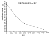
图2a为说明本发明一种示范实施例中起始系统温度为起始脉压的函数的表图。 Figure 2a is a graph illustrating initial system temperature as a function of initial pulse pressure in an exemplary embodiment of the present invention. the
图3为说明图1中第二(振动产生)过程的示范实施例的操作流程图。 FIG. 3 is a flowchart illustrating the operation of an exemplary embodiment of the second (vibration generating) process of FIG. 1 . the
图3a为说明确定图3中下次振动对序列和执行该振动对的示范流程图。 FIG. 3a is an exemplary flowchart illustrating determining the next vibration pair sequence of FIG. 3 and executing the vibration pair. the
图3b为说明根据本发明一种实施例的产生、转换、烘焙单位振动的示范流程图。 Figure 3b is an exemplary flow diagram illustrating the generation, conversion, and baking unit vibrations according to one embodiment of the present invention. the
图3c为说明根据本发明的一种实施例的收集脉冲数据的一种示范过程流程图。 Figure 3c is a flow diagram illustrating an exemplary process for collecting pulse data according to one embodiment of the present invention. the
图3d为说明根据本发明的原理,适用于转换率限制时,固定扁平振动大小缺点的表图。 Figure 3d is a graph illustrating the drawbacks of a fixed planar vibration magnitude when applied to slew rate limitations in accordance with the principles of the present invention. the
图3e为说明根据本发明的一种实施例的仅扁平振动的几率作为温度函数的表图。 Figure 3e is a graph illustrating the probability of flat vibration only as a function of temperature according to one embodiment of the invention. the
图3f为说明根据本发明的一种实施例的温度系数作为温度的函数的表图。 Figure 3f is a graph illustrating temperature coefficient as a function of temperature according to one embodiment of the present invention. the
图3g为说明根据本发明的一种实施例的温度作为收集的脉动次数函数的表图。 Figure 3g is a graph illustrating temperature as a function of the number of pulses collected according to one embodiment of the invention. the
图4为说明根据本发明的一种示范实施例的第三过程(例如,血液动力学参数处理过程)的操作流程图。 FIG. 4 is a flowchart illustrating the operation of a third process (eg, hemodynamic parameter processing process) according to an exemplary embodiment of the present invention. the
图4a为说明根据本发明的一种实施例的PMM偏差作为平均压函数的表图。 Figure 4a is a graph illustrating PMM deviation as a function of mean pressure according to one embodiment of the present invention. the
图4b为说明根据本发明的一种实施例的PMM偏差温度因子作为温度函数的表图。 Figure 4b is a graph illustrating PMM bias temperature factor as a function of temperature according to one embodiment of the present invention. the
图4c为说明根据本发明的一种实施例的delta能量作为delta脉压的函数。 Figure 4c is a graph illustrating delta energy as a function of delta pulse pressure according to one embodiment of the present invention. the
图4d为说明根据本发明的一种实施例的转换几率作为脉压和温度的函数的表图。 Figure 4d is a graph illustrating switching probability as a function of pulse pressure and temperature according to one embodiment of the present invention. the
图5为说明图1一种示范实施例的第四过程(例如,系统的适应行为)的操作流程图。 FIG. 5 is an operational flow diagram illustrating a fourth process (eg, adaptive behavior of the system) of an exemplary embodiment of FIG. 1 . the
图5a为说明根据本发明的一种实施例的平均数作为温度负担(tax)的函数的表图。 Figure 5a is a graph illustrating averages as a function of temperature tax (tax) according to one embodiment of the present invention. the
图6为根据本发明用于活体血管内血液动力学参数评估的装置的一种示 范实施例的框图。 Fig. 6 is a block diagram of an exemplary embodiment of a device for evaluating hemodynamic parameters in a living blood vessel according to the present invention. the
具体实施方式 Detailed ways
现在参考附图,其中在全文中相似的数字代表相似的部件。 Referring now to the drawings, wherein like numerals represent like parts throughout. the
注意,在此主要是根据控制非侵入性测量血液动力学参数的装置和方法来描述本发明,例如由人体桡骨(即腕)测血压。本发明还可在人体其它血管和位点随时实现或调整监测那些参数,以及监测其它温血物种的这些参数。类似地,本发明的技术可以适用于其它参数,以及具有和活体循环系统相似特性的其它类似流体系统。所有这些适应性和供选择的实施例都易于通过相关领域的一般技术实现,并认为落入本发明权利要求的范围。 Note that the present invention is mainly described here in terms of an apparatus and method for controlling non-invasive measurement of hemodynamic parameters, such as measuring blood pressure from the radius (ie, wrist) of a human body. The present invention can also enable or adjust monitoring of those parameters over time in other blood vessels and sites of the human body, as well as monitoring of these parameters in other warm-blooded species. Similarly, the techniques of the present invention can be adapted to other parameters, and other similar fluid systems with similar properties to the living circulatory system. All such adaptations and alternative embodiments are readily accomplished by ordinary skill in the relevant art and are considered to fall within the scope of the claimed invention. the
此处所用术语“连续的”意思是包括无限制连续的、逐段连续的、和/或大体上连续的过程(例如,通常实质上连续,但本身不连续的那些)。 The term "continuous" as used herein is meant to include without limitation continuous, piecewise continuous, and/or substantially continuous processes (eg, those that are often substantially continuous, but are not themselves continuous). the
此处所用术语“血液动力学参数”意思是包括与主体的循环系统相关的参数,包括例如血压(如舒张压、收缩压、脉压或平均压),其派生物或结合物,动脉血流,动脉壁直径(及其派生物),动脉横截面积和动脉顺应性。 The term "hemodynamic parameters" as used herein is meant to include parameters related to the circulatory system of a subject, including, for example, blood pressure (such as diastolic, systolic, pulse or mean pressure), derivatives or combinations thereof, arterial blood flow , arterial wall diameter (and its derivatives), arterial cross-sectional area, and arterial compliance. the
此外,注意此处使用的术语“测量张力的”,“张力测量器(血压计)”,“张力测定法”旨在概括表示一个或多个血液动力学参数的非侵入性表面测量,例如将传感器与皮肤表面相连,虽然与皮肤相接触,但无需直接接触,可以是间接的(例如通过连接介质或其它接触面)。 In addition, note that the terms "tonic", "tensometry (sphygmomanometer)", "tensometry" as used herein are intended to generally mean the non-invasive superficial measurement of one or more hemodynamic parameters, e.g. The sensor is attached to the skin surface, although it is in contact with the skin, it does not need to be in direct contact, but can be indirect (eg, through a connecting medium or other contact surface). the
此处使用的术语“压平”和“扁平”并不加以限制,指主体生理学上的组织、血管和其它结构如腱或肌肉的压缩(相对于非压缩状态)。类似地,扁平“扫描”指扁平指数变化的(增大、减小或其任意组合)一个或多个时间段。术语“扁平”通常在线性(恒定速度)位置变化中应用,但是此处可以表示在任何想得到的任何其它形式的变化,包括而不限于(i)随时间变化的连续非线性的(如对数的)增大或减小的压缩;(ii)非连续或逐段连续的线性或非线性的压缩;(iii)交替压缩或松驰;(iv)正弦曲线或三角波函数;(v)随机运动(例如“随机行走”);或(vi)确定的轮廓。所有这些形式都被看作是这些术语所包含的。 The terms "flattened" and "flattened" are used herein without limitation and refer to the compression (relative to the uncompressed state) of tissues, blood vessels and other structures such as tendons or muscles in the physiology of a subject. Similarly, a flat "sweep" refers to one or more time periods in which the flat index changes (increases, decreases, or any combination thereof). The term "flat" is usually applied to linear (constant velocity) changes in position, but here may mean changes in any other form conceivable, including but not limited to (i) continuous non-linear (e.g. logarithmic (ii) discontinuous or piecewise continuous linear or nonlinear compression; (iii) alternating compression or relaxation; (iv) sinusoidal or triangular wave functions; (v) random motion (eg "random walk"); or (vi) defined contours. All of these forms are considered to be encompassed by these terms. the
此处所用的术语“时期”涉及任何时间增量,持续时间从秒的最小可测量段到大于1秒。 The term "period" as used herein refers to any increment of time, ranging in duration from the smallest measurable fraction of a second to greater than 1 second. the
此处所用术语“空间的”和“位置”虽然是按照有扁平(如,Z-轴),横向(X-轴)和(近端指靠近心脏)纵向或(近端-远端)(Y-轴)分量的笛卡儿坐标系来描述,但其应该指任何空间坐标系,包括但不限于圆柱形、球形和两级形。该可替换的坐标系可以明显地独立于任何硬件配置或几何学(如,通过完成基于笛卡尔的仪器和非笛卡尔坐标系之间简单的数学转化),或选择性地有利地使用该几何学。因此,本发明当然不限于仪器配置的某些坐标系。举一个例子,本发明的仪器和方法可用围绕桡动脉为模型的圆柱形坐标系来实现,可通过Z、r和θ参数具体指定测量张力的传感器在空间内特定的点。这种方法具有优势,因为人类的前臂/腕部大体上为圆柱形状。 The terms "spatial" and "positional" are used here although in terms of flat (e.g., Z-axis), transverse (X-axis) and (proximal means near the heart) longitudinal or (proximal-distal) (Y - axis) components, but it shall refer to any spatial coordinate system, including but not limited to cylindrical, spherical and bipolar. This alternative coordinate system can be clearly independent of any hardware configuration or geometry (e.g., by performing a simple mathematical transformation between Cartesian-based instruments and non-Cartesian coordinate systems), or it can be selectively used to advantage study. Therefore, the invention is of course not limited to certain coordinate systems for instrument configurations. As an example, the apparatus and methods of the present invention can be implemented with a cylindrical coordinate system modeled around the radial artery, and the tension-measuring transducer can be specified at a particular point in space by the Z, r, and theta parameters. This approach is advantageous because the human forearm/wrist is generally cylindrical in shape. the
此处所用术语“温度”指但不限于在实际或物理退火过程中,与温度相关或类似的任何参数,包括例如置信度。此处公开的退火模型中使用的温度仅是一个抽象概念,代表与受控或模仿系统相关的数量或属性。 The term "temperature" as used herein refers to, but is not limited to, any parameter related to or similar to temperature during actual or physical annealing, including, for example, confidence. The temperature used in the annealing models disclosed here is only an abstraction representing quantities or properties relevant to controlled or simulated systems. the
此处所用的术语“应用”(软件应用领域)一般指完成一定功能或主题的可执行的软件单元。应用主题在许多学科和功能中各不相同(例如按需内容管理,电子商务交易、经纪交易、家庭娱乐、计算器等),一项应用可包含一个以上的主题。可执行软件的单元通常在预定的环境中运行,例如该单元可包括在Java TVTM环境中运行的可下载的Java XletTM。 The term "application" (software application field) used here generally refers to an executable software unit that accomplishes a certain function or theme. Application themes vary across many disciplines and functions (e.g. on-demand content management, e-commerce transactions, brokerage transactions, home entertainment, calculators, etc.), and an application can contain more than one theme. A unit of executable software typically runs in a predetermined environment, for example the unit may comprise a downloadable Java Xlet( TM ) running in a Java TV (TM) environment.
此处所用术语“计算机程序”或“软件”表示包括执行功能的任何序列或者人类、机器可认知的步骤。该程序实质上可纳入任何编程语言或环境,包括例如C/C++、Fortran、COBOL、PASCAL,组合语言,标记语言(如HTML,SGML,XML,VoXML)等,以及面向对象环境,例如公用对象请求代理体系结构(CORBA),JavaTM(包括J2ME,Java Beans等)等。 The term "computer program" or "software" as used herein means any sequence or steps recognizable by humans or machines to perform functions. The program can be incorporated into virtually any programming language or environment including, for example, C/C++, Fortran, COBOL, PASCAL, assembly languages, markup languages (such as HTML, SGML, XML, VoXML), etc., and object-oriented environments such as Common Object Request Proxy Architecture (CORBA), Java TM (including J2ME, Java Beans, etc.), etc.
此处所用术语“集成电路(IC)”指具有任意集成程度(包括但不限于ULSI,VLSI和LSI)的任意类型的设备,不管其过程或基本材料如何(包括但不限于Si、SiGe、CMOS和GaAs)。IC可包括,例如:存储设备(例如DRAM、SRAM、DDRAM、EEPROM/Flash、ROM),数字处理器,SoC器件,FPGA,ASIC,ADC,DAC,收发器,存储控制器和其它设备,及其任意组合。 The term "integrated circuit (IC)" as used herein refers to any type of device with any degree of integration (including but not limited to ULSI, VLSI and LSI), regardless of its process or base material (including but not limited to Si, SiGe, CMOS and GaAs). ICs may include, for example: memory devices (e.g., DRAM, SRAM, DDRAM, EEPROM/Flash, ROM), digital processors, SoC devices, FPGAs, ASICs, ADCs, DACs, transceivers, memory controllers, and other devices, and random combination. the
此处所用术语“存储器”包括适用于存储数字数据的任意类型的集成电路或其它存储设备,包括但不限于ROM,PROM,EEPROM,DRAM,SDRAM,DDR/2 SDRAM,EDO/FPMS,RLDRAM,SRAM,闪存存储器(例如, NAND/NOR)和PSRAM。 The term "memory" as used herein includes any type of integrated circuit or other memory device suitable for storing digital data, including but not limited to ROM, PROM, EEPROM, DRAM, SDRAM, DDR/2 SDRAM, EDO/FPMS, RLDRAM, SRAM , Flash memory (eg, NAND/NOR) and PSRAM. the
此处所用术语“处理器”,“微处理器”和“数字处理器”指一般包括各种类型的数字处理设备,包括但不限于数字信号处理器(DSP),精简指令集计算机(RISC),通用(CISC)处理器,微处理器,门列阵(例如FPGA),PLD,可重配置计算结构(RCF),阵列处理器和专用集成电路(ASIC)。这些数字处理器可以被包含在一个单一的集成电路芯片中,或分布在多个组件中。 The terms "processor", "microprocessor" and "digital processor" as used herein refer generally to various types of digital processing devices, including but not limited to digital signal processors (DSP), reduced instruction set computers (RISC) , general-purpose (CISC) processors, microprocessors, gate arrays (such as FPGAs), PLDs, reconfigurable computing fabrics (RCFs), array processors, and application-specific integrated circuits (ASICs). These digital processors can be contained on a single integrated circuit chip, or distributed among multiple components. the
概述 overview
在一个基本方面,本发明包括控制生理分析中应用的扁平或其它定位机制的装置和方法,例如,非侵入性测量血液动力学参数,尤其为了维持参数传感器和所关注血管之间的最佳连接。这些改进的装置和方法基于模拟退火(SA)模式,提供了实质上统一的和高度有效的手段,使血液动力学评估或其它此类系统处于并维持优化运行状态。这种状态的维持与被测参数(如血压)尽可能最好的准确度尤其相关。 In one fundamental aspect, the present invention includes devices and methods for controlling applanation or other positioning mechanisms used in physiological analysis, for example, non-invasively measuring hemodynamic parameters, especially in order to maintain an optimal connection between the parameter sensor and the vessel of interest . These improved devices and methods, based on a simulated annealing (SA) model, provide a substantially uniform and highly efficient means of bringing and maintaining an optimal operating state for hemodynamic assessment or other such systems. Maintenance of this state is especially relevant with the best possible accuracy of the measured parameter (eg blood pressure). the
确定最佳压级、定位和连接的示范技术可以由本发明利用,或者得益于本发明。该示范技术在例如2004年5月4日公开的名称为“Method And ApparatusFor Non-Invasively Measuring Hemodynamic Parameters Using Parametrics(使用参数学非侵入性测量血液动力学参数的方法和仪器)”的共有美国专利No.6,730,038和2005年12月13日公开的名称为“Method and Apparatus forControl of Non-Invasive Parameter Measurements(控制非侵入性参数测量的方法和仪器)”的共有美国专利No.6,974,419中有详细描述,在此将其完全包括并作为参考。 Exemplary techniques for determining optimum pressure levels, positioning, and connections may be utilized by, or benefit from, the present invention. This demonstrative technology is published on May 4, 2004, for example, in the jointly owned U.S. Patent No. .6,730,038 and commonly-owned U.S. Patent No. 6,974,419, published on December 13, 2005, entitled "Method and Apparatus for Control of Non-Invasive Parameter Measurements (Method and Apparatus for Control of Non-Invasive Parameter Measurements)" are described in detail in It is hereby included in its entirety and by reference. the
本发明改进的技术和装置被有益地与广泛的硬件配置同时使用,包括例如在本申请和上述引入的共同待决申请中详细描述的单一传感器(或一系列传感器),或者与适合血液动力学参数测量的任何类型的其它装置结合地使用,包括例如下述共同待决美国专利申请中所描述的设备:2001年3月22日提交的名称为“Method and Apparatus for the Noninvasive Assessment of HemodynamicParameters Including Blood Vessel Location(用于非侵入性评估包括血管位点的血液动力学参数的方法和装置)”的专利申请No.09/815,982以及2001年3月22日提交的名称为“Method and Apparatus for Assessing Hemodynamic Parameters within the Circulatory System of a Living Subject(用于评估活体循环系统内血液动力学参数的方法和装置)”的专利申请No.09/815,080,二者均已转让本受让人,在此将其完全包括并作为参考。例如,可以使用完全基于张力测量血压的方法。供选择地,通过血液流动的动能或速度超声测量血压可作为基于张力测量血压方法的验证技术。作为另一例子,以与血管壁检测相关的声波信号分析为基础的横向定位,可以在引用的共有专利和专利申请中描述的基于压力的技术之外使用(或者取代使用)。 The improved techniques and devices of the present invention are beneficially used with a wide range of hardware configurations, including, for example, a single sensor (or series of sensors) as described in detail in this application and the above-incorporated co-pending applications, or with suitable hemodynamic Any type of other device for parameter measurement, including, for example, the device described in the following co-pending U.S. patent application: filed March 22, 2001 entitled "Method and Apparatus for the Noninvasive Assessment of Hemodynamic Parameters Including Blood Vessel Location (for non-invasive assessment of hemodynamic parameters including vascular sites)" patent application No. 09/815,982 and filed on March 22, 2001 titled "Method and Apparatus for Assessing Hemodynamic Parameters within the Circulatory System of a Living Subject (method and device for assessing hemodynamic parameters within the living body circulatory system)", both of which have been assigned to the assignee, are hereby incorporated Fully included and by reference. For example, blood pressure measurements based entirely on tension can be used. Alternatively, ultrasonic measurement of blood pressure via the kinetic energy or velocity of blood flow can be used as a validation technique for tonometry-based blood pressure methods. As another example, lateral localization based on analysis of acoustic signals associated with vessel wall detection may be used in addition to (or in place of) the pressure-based techniques described in the cited co-owned patents and patent applications. the
因此,本发明的各个方面有利地与许多不同的生理学和血液动力学评估技术兼容。此处描述的技术和装置决不限于测量张力的应用;或者说,这些特征还可在例如封闭袖带或基于佩洛(pellot-based)的系统中应用。 Thus, aspects of the invention are advantageously compatible with many different physiological and hemodynamic assessment techniques. The techniques and devices described here are in no way limited to tension-measuring applications; rather, these features can also be applied, for example, in closed cuffs or pellot-based systems. the
虽然上述共同未决专利和专利申请中描述的技术已经由受让人确定为高度有效,但通过增加本发明的一个或多个不同方面,它们在实际环境中(例如临床)的坚固性和实用性得到增强。血压测量中,获得和测量患者平均动脉血压的现存方法集中于在被关注动脉(如桡动脉)的上方压缩患者的组织,以便观察到的血压被最大化。正是在最大脉压这一点上,压缩动脉上施加的压力等于平均动脉压。以准确的方式观察平均动脉压主要以正确定位动脉和在适当扁平程度上压缩动脉为基础。 While the techniques described in the aforementioned co-pending patents and patent applications have been determined by the assignee to be highly effective, their robustness and utility in practical settings, such as clinical Sex is enhanced. In blood pressure measurement, existing methods of obtaining and measuring a patient's mean arterial blood pressure focus on compressing the patient's tissue over the artery of interest (eg, the radial artery) so that the observed blood pressure is maximized. It is at the point of maximum pulse pressure that the pressure exerted on the compressed artery equals the mean arterial pressure. Observing mean arterial pressure in an accurate manner is primarily based on correct positioning of the arteries and compression of the arteries to an appropriate degree. the
这样一些方法中,用分立的两个步骤或两个阶段完成动脉的定位。首先,在初始校准阶段,通过沿横向轴和扁平轴做广泛的移动完成所取空间的狭小部分的扫描。其次,在第二操作阶段,在校准阶段定位的当前操作点周围,利用一系列小的实验的振动很好地调整扁平位置。以这种方式,动脉定位和扁平的两个阶段可被看作是“大信号实验”和之后的“小信号实验”。 In such methods, the location of the artery is accomplished in two discrete steps or stages. First, during the initial calibration phase, scanning of a narrow portion of the captured space is done by making wide movements along the transverse and flat axes. Second, during the second operating phase, the flat position is well adjusted using a series of small experimental vibrations around the current operating point located during the calibration phase. In this way, the two phases of artery localization and flattening can be viewed as a "large signal experiment" followed by a "small signal experiment". the
通常,大信号实验比小信号实验好或差的比较是没有意义的,通过实施这种方法测量,给系统带来一些问题。首先,观察到的脉压可能不仅与动脉传感器的实际位置有关,还很有可能与致动器在所涉及组织上的施压历史有关。因此,可以合理地预期,这种过去的影响会随在初始校准过程中所看到的系统的更大干扰而增强,这种历史效应(historical effect)可能扩大是可以合理预料到的。 Often, it is meaningless to compare large-signal experiments as better or worse than small-signal experiments, and by implementing this method of measurement, it brings some problems to the system. First, the observed pulse pressure may not only be related to the actual location of the arterial sensor, but also, most likely, the history of the actuator's pressure on the involved tissue. Thus, it is reasonable to expect that this past effect will increase with greater perturbations to the system as seen during the initial calibration, and it is reasonable to expect that this historical effect may be amplified. the
第二,采用两个分离操作模式假定系统(例如传感器、执行器和患者的组织)在大信号和小信号实验过程中反应相似,实际上是假定系统以线性方式运 转。然而,初始校准阶段定位的操作点和第二阶段定位的操作点可能只是适合它们各自操作阶段的两个不同“答案”。校准之后的扁平位置和横向位置只作小调整的系统中,这种两阶段的解决方法是存在问题的,因为校准过程定位的操作点可能不是第二阶段理想的操作位点,控制系统有陷于局部最大的倾向,而不是全局最大。 Second, employing two separate modes of operation assumes that the system (such as sensors, actuators, and patient tissue) responds similarly during large-signal and small-signal experiments, effectively assuming that the system behaves in a linear fashion. However, the operating point located in the initial calibration phase and the operating point located in the second phase may just be two different "answers" suitable for their respective phases of operation. This two-stage solution is problematic in systems where only small adjustments to the flat position and lateral position are made after calibration, because the operating point positioned by the calibration process may not be the ideal operating point in the second stage, and the control system is stuck. Tendency to be a local maximum rather than a global maximum. the
因此,根据本发明的一个实施例,提供在单一统一体系下工作,以连续和非侵入方式监测血液动力学参数(如血压)的方法和装置。在某种意义上,这种方法承认这样的事实:我们不断地校准,总是询问我们是否在患者的最佳操作点测量所要的动力学参数。本发明的一个实施例包括用于测量与人体相关的各种血液动力学参数的测量装置。另外,还公开了用于相应于所测参数而计算各种参数的数字处理器。同时,本发明包括用于相应于数字处理器产生的信息而控制测量位置的方法和装置。 Therefore, according to one embodiment of the present invention, there are provided methods and devices for monitoring hemodynamic parameters, such as blood pressure, in a continuous and non-invasive manner, working in a single unified system. In a sense, this approach acknowledges the fact that we are constantly calibrating, always asking whether we are measuring the desired kinetic parameter at the patient's optimal operating point. One embodiment of the invention includes a measuring device for measuring various hemodynamic parameters related to the human body. Additionally, a digital processor for calculating various parameters corresponding to the measured parameters is also disclosed. Also, the present invention includes a method and apparatus for controlling the measurement position corresponding to the information generated by the digital processor. the
根据所描述的血液动力学系统监测装置的实施例,该血液动力学系统装置实现了在单一的操作体系下统一测量的“模拟退火”过程。在一种模拟退火过程的示范实施例中,将不同大小的振动动态地应用于给定操作点周围的系统。这些振动的大小与置信分析(如,所谓的温度测量)相关,当置信度低时,应用振动变化大,置信度高时,应用更小的更细微的变化。这种模拟退火过程更灵活地应对被现有技术所谓的局部最大值所限,以及灵活应对血液动力学参数曲线的不同拓扑结构。该方法还为所允许的最大量打开了解决空间,通过实施的物理致动器(如通过考虑逐次地或平行地调整扁平、横向和末端轴)和通过进一步考虑动态调整桡动脉上传感器的位置,进一步改善这几类非侵入性血液动力学参数监测仪的可靠性和坚固性。此外,因为该统一体系主要为“小信号”途径,尽管未必如此,但由于如上述最佳定位置信水平的破坏对系统的影响,致使错误的非侵入性读数实际上被最小化。 According to the described embodiment of the hemodynamic system monitoring device, the hemodynamic system device realizes a "simulated annealing" process of unified measurement under a single operating system. In an exemplary embodiment of a simulated annealing process, vibrations of different magnitudes are dynamically applied to the system around a given operating point. The magnitude of these vibrations is related to the confidence analysis (eg, so-called thermometry), when the confidence level is low, large vibration changes are applied, and when the confidence level is high, smaller more subtle changes are applied. This simulated annealing process is more flexible to be limited by the so-called local maxima of the prior art, and to different topologies of the hemodynamic parameter curves. The method also opens up the solution space for the maximum amount allowed, by implementing physical actuators (e.g., by considering sequential or parallel adjustments of the flat, transverse, and distal axes) and by further considering dynamically adjusting the position of the sensor on the radial artery , to further improve the reliability and robustness of these types of non-invasive hemodynamic parameter monitors. Furthermore, because the unified system is primarily a "small signal" approach, although not necessarily so, false non-intrusive readings are practically minimized due to the impact on the system of disruption of optimal location confidence levels as described above. the
连续定位方法学 Continuous Positioning Methodology
还应认识到,当就测量张力的压力传感器或传送器描述本发明的方法时,它可更普遍地适用于其它信号领域,包括但不限于超声波和电磁辐射(如IR,X-光线等)。 It should also be appreciated that while the method of the present invention is described in terms of pressure sensors or transmitters that measure tension, it is more generally applicable to other signal fields, including but not limited to ultrasound and electromagnetic radiation (e.g. IR, X-ray, etc.) . the
此外,应理解的是,虽然主要在上述张力测量仪器中加以描述(例如还提 供对下面组织和血管不同的压缩水平的测量张力的压力传感器),但本发明的方法是通过提供这些功能的具有独立组件的装置来实施的。例如,压力传感器的控制可以部分或全部地与扁平控制系统分离,以至于扁平水平可以独立地不同于传感器有效表面的连接。此处所描述的用于支持过程的运行的电子和信号处理仪器的范例,其详细讨论见相关附图6. Furthermore, it should be understood that while primarily described in the context of the above-described tonometers (e.g., pressure transducers that also provide measurement of tension to varying levels of compression of underlying tissue and blood vessels), the method of the present invention is achieved by providing these functions implemented as a device with independent components. For example, the control of the pressure sensor can be partly or completely separated from the flat control system, so that the level of the flat can be independently different from the connection of the active surface of the sensor. An example of the electronics and signal processing instrumentation used to support the operation of the process described here is discussed in detail in the associated Figure 6.
本领域普通技术人员应该认识到,本发明的逻辑过程还可完全在算法上(如以软件)和/或固件来实施。 Those of ordinary skill in the art will recognize that the logical processes of the present invention may also be implemented entirely in algorithms (eg, in software) and/or firmware. the
图1为说明根据本发明的一个实施例的实行一般控制方法学确定如活体血液动力学参数(血压等)的流程图。整个过程可看作构成4个基本的方法学步骤。第一步102包括进入“模拟退火”处理和随后那些步骤的预先必要的计算。该步骤102在表2及其附带公开的内容中进一步详细描述。
FIG. 1 is a flow chart illustrating the implementation of a general control methodology for determining eg in vivo hemodynamic parameters (blood pressure, etc.) according to one embodiment of the present invention. The whole process can be seen as constituting four basic methodological steps. The
应理解的是,此处所用术语“模拟退火”仅作为类似的概念使用,为了更容易地理解本发明的概念,决不带有任何特定涵义。 It should be understood that the term "simulated annealing" used here is only used as a similar concept, and never has any specific meaning in order to understand the concept of the present invention more easily. the
在步骤104,启动变化(如振动)产生处理流程。振动因素的设定代表性地包括扁平振动因素,横向振动因素和远端振动因素,分别对应于测量仪器的扁平轴,横向轴和远端轴。振动产生处理流程就图3及其附带的公开的内容做进一步讨论。本文中描述的本发明可选择的实施例可包括想到的或多或少的振动因素和/或轴。给出本发明公开的内容后,本领域普通技术人员很容易实现本发明。
At
步骤106对应本发明一个实施例中使用的压力信号处理方法学。该方法学进一步或部分在图4及其附带公开的内容中详细描述。 Step 106 corresponds to the pressure signal processing methodology used in one embodiment of the present invention. This methodology is further or partially described in detail in Figure 4 and its accompanying disclosure. the
在步骤108中,以上述振动产生和血液动力学参数处理步骤为基础调整系统行为。一般来讲,随着处于最佳点的置信水平减少,振动因素增加,以便考虑“较大范围”寻找最佳定位点,该最佳点为从中获得血液动力学参数读数的最佳位置。相反地,当置信水平增加时,振动因素减少,为了仅允许“较小范围”寻找最佳点以获得血液动力学参数读数,且同时减小对系统的不利影响,作为非侵入性测量的结果。这种自适应行为在图5及其附带公开的内容中进一步详细讨论。
In
此时,处理流程100可结束,或选择继续,在102执行新的测量,并重复上述处理流程一次或多次。尽管认识到更多或更少的轴处理步骤都符合本发明 的原理,可以实现,但为了简洁明了,过程102、104、106和108主要仅就所关注的两条轴讨论(如扁平轴和横向轴)。
At this point, the
(1)模拟退火入口 (1) Simulated annealing entrance
现参考图2,显示了模拟退火入口步骤102的一个示范实施例,描述了示范性模拟退火处理,结合计量血压的血压监控系统的使用,如TL-150,由 
在步骤202中,将血压传感器沿扁平轴压在期望的位置,例如,由使用者确定的触诊标记(palpation mark),或由如超声等血管定位机制或技术确定的位置。在第一实施例中,触诊标记由手动确定,首先触摸桡骨茎突,然后在骨上画上横线。接着,确定患者脉搏位置,使用者可以画上与先前横线垂直相交的直线。这条相交的线在此处即为触诊标记。虽然用沿患者腕上桡骨茎突的定位进行讨论,但此处描述的触诊技术可同样适用于人体的其它区域,比如尺脉冲点、颈脉冲点或肱脉冲点等。然后将测量仪器置于触诊标记上,血压传感器压患者触诊标记处的组织,达到指定的扁平压力(如85mm-Hg)。
In
在步骤204中,确定该装置是否能检测源自脉冲点(如桡脉冲点触诊标记)的脉冲节拍。如果检测到脉冲,那么该装置将取在特定数量(如,4次)的脉动中观察的平均脉压,或采用另一方案获取在步骤206中设定的期望的数据,并且该处理流程随后会在步骤208调用有平均脉压测量的模拟退火处理流程。如果没有检测到脉冲,那么在步骤205调用“混合”横向处理步骤。
In step 204, it is determined whether the device can detect pulse beats originating from pulse points (eg, radial pulse point palpation marks). If a pulse is detected, the device will take the average pulse pressure observed over a specified number of pulses (e.g., 4), or use another scheme to obtain the desired data set in
假定还未检测到脉冲节拍,则在步骤205调用混合横向处理步骤。此时,装置通过执行横向扫描开始搜寻脉动,该横向扫描从距可能的横向移动起始处特定距离的点开始。通过实验发现,虽然明显地也可进行更多或更少的移动,但距可能的横向移动的起始处的移动的特定距离通常最有效地大约为1/4英寸(0.25in.)。 Assuming no pulse beat has been detected, at step 205 a hybrid transverse processing step is invoked. At this point, the device begins to search for pulses by performing a lateral scan starting from a point at a certain distance from the start of a possible lateral movement. It has been found through experimentation that the specific distance of movement from the origin of possible lateral movement is generally most effective on the order of 1/4 inch (0.25 in.), although more or less movement is clearly possible. the
接着,仪器将“伺服”(如连续或半连续地变化)扁平位置,以便维持特定位置上的平均压力,例如60mm-Hg。横向扫描过程中,装置收集的任何脉动都与检测时传感器的位置和压力读数一起记录下来。 The instrument will then "servo" (eg, continuously or semi-continuously vary) the flat position in order to maintain an average pressure, eg, 60 mm-Hg, at a particular location. During the transverse scan, any pulsations picked up by the device are recorded along with the sensor's position and pressure readings at the time of detection. the
此时在混合横向处理中,装置判断其是否收集到预定数量的脉动(如在举例的实施例中的4次),或在没有检测到所需数量的脉动时就已经到达横向移动的终点。如果在没有检测到特定数量的脉动时就已经到达特定横向移动的终点,就需重复步骤205;然而这次使用更低的横向扫描速度,和/或增加可能的横向移动范围。
At this point in the hybrid traverse process, the device determines whether it has collected a predetermined number of pulses (eg, 4 in the example embodiment), or has reached the end of the traverse without detecting the required number of pulses. If the end of a certain lateral movement has been reached without detecting a certain number of pulsations,
另一方面,如果收集到预定数量的脉动,传感器将被定位在横向某个位置上,该位置是通过收集到的脉动的最大读数显示出来。在该点上,装置将伺服传感器的扁平位置,直到达到期望的平均压(如85mm-Hg),并在步骤207收集另一预定次数的脉动。
On the other hand, if a predetermined number of pulsations are collected, the sensor will be positioned at a lateral position indicated by the maximum reading of pulsations collected. At this point, the device will servo the flat position of the sensor until the desired mean pressure (eg, 85 mm-Hg) is reached, and collect another predetermined number of pulses at
在步骤207,作为动作恢复处理的结果,如果确定进入步骤205的混合横向处理,那么收集的脉动数量将为某个特定数目,例如20次。如果不是动作恢复处理的结果,则需要收集较少数量的脉动,例如4次。然后装置也查询特定时限内是否收集到所需次数的脉动,如果装置对该查询返回“是”,则装置将收集脉动期间收集的脉压测量平均化,并调用步骤208,即模拟退火处理流程。
In
如果在收集到特定次数的脉动之前装置超时,则重复混合横向处理,但扫描速度降低。如果该重复的混合横向处理超过了预定的重复次数(如2次),那么将提示使用者处理错误,同时该处理流程终止,或在需要时进入诊断或检修模式。 If the device times out before a specified number of pulses are collected, the mixed transversal process is repeated, but with a reduced scan rate. If the repeated mixed transversal process exceeds a predetermined number of repetitions (eg, 2 times), the user will be prompted to process an error, and the process flow will be terminated, or enter a diagnostic or maintenance mode if necessary. the
在步骤208中,调用模拟退火处理尤其为进入随后的振动产生处理步骤做准备,如下在图3及其附带公开的内容中进一步描述。在步骤208,用图2a的表图选择起始温度值,该表图显示起始温度是初始脉压的函数。图2a证明了所选起始温度(相对单位)对初始脉压(mm-Hg)之间的函数关系。为了硬件简单,用1-D内插器完成图2a表中步骤208过程中起始温度对初始脉压的逐段线性内插。然而还可能有更复杂的内插法,或适合算法的曲线,例如多项式或甚至样条内插法。
In
(2)振动产生 (2) Vibration generation
现参考图3,详细讨论振动产生104的示范方法。在高水平上,示范的振动产生过程104涉及三个基本操作步骤:(1)确定下一个振动对序列302;(2) 执行振动对316;和(3)根据预定方案同步(clocking)温度控制器350。
Referring now to FIG. 3 , an exemplary method of
关于步骤(1)和(2),即振动对的确定和执行,这些处理步骤将在图3a、3b和3c中详细讨论。 With regard to steps (1) and (2), ie determination and execution of vibration pairs, these processing steps will be discussed in detail in Figures 3a, 3b and 3c. the
关于步骤(3),在步骤352,装置内的逻辑程序将确定温度控制器是否已经同步预先指定的数值(如2次);如果逻辑程序返回“是”,则在步骤356以规定的量(例如1个click)降低当前温度。如果工作程序返回“否”,则在步骤354保持当前温度。
Regarding step (3), in
现参考图3a,详细描述确定下一个振动对序列302的处理流程的示范实施例。当评价传感器装置的两个不同位置时,振动对序列确定所用“实验”或试验的顺序。因此一个振动对序列可看作是控制这种统一方案下的传感器位置的模拟退火处理流程的核心或“心脏”。
Referring now to Figure 3a, an exemplary embodiment of a process flow for determining the next
在本发明的实施例中,振动对序列实质上是随机的,或许可通过举例很好地解释其原因。例如,设想患者脉压的活动实际上与装置运动无关。如果该活动涉及大量时间周期内单调的变化,如因特定的生理或药理作用,确定“实验”或试验的顺序将对测试结果产生很容易预测的不良影响。例如,在患者脉压单调递增的情况下,这种增长比通过移动传感器的位置所施加的任何影响都强,通常在振动对上无论哪个位置测试都占优势,设想它将具有更高的观测的脉压(因为我们正单调递增压力)。在这种情况下,传感器位置几乎不离开先前确定的位置。相反,如果在每个振动对中总是以上次振动位置结束,传感器的位置总是趋于离开每个振动对而趋向随机选择的振动。为了消除这种效应,振动对的顺序是随机的,用外部脉压变化有效地消除了长期偶然的和非因果的关系。不过,还可使用其它方案避免这种效应,包括具体分析可能造成的影响(如上述单调的情况)以及适当地制定一个方案消除或减轻这种有害影响。此外,可能并不总是需要随机,因此也可在需要时选择性应用。 In an embodiment of the invention, the sequence of vibration pairs is essentially random, perhaps best explained by example. For example, imagine that the activity of the patient's pulse pressure is virtually independent of device motion. If the activity involves monotonic variation over a large period of time, such as due to specific physiological or pharmacological effects, determining the "experiment" or the order of the trials will have an easily predictable adverse effect on the test results. For example, in the case of a monotonically increasing patient pulse pressure, this increase is stronger than any effect exerted by moving the position of the sensor, usually on a vibration pair whichever position is tested predominates, it is conceivable that it will have a higher observed The pulse pressure of (since we are monotonically increasing the pressure). In this case, the sensor position hardly deviates from the previously determined position. Conversely, if in each vibration pair always ends up with the last vibration position, the sensor's position always tends away from each vibration pair towards a randomly chosen vibration. To eliminate this effect, the order of the vibration pairs is randomized, effectively eliminating long-term casual and non-causal relationships with external pulse pressure variations. However, other options can be used to avoid this effect, including specific analysis of possible impacts (such as the monotonic case above) and appropriate development of a program to eliminate or mitigate such harmful effects. Also, randomization may not always be needed, so it can also be applied selectively when needed. the
正如数学领域所知道的,信号和/或数字序列的随机化最典型的是通过使用所谓的伪随机数发生器产生伪随机二进制序列(PRBS)。伪随机二进制序列(PRBS)是输入(+/-1)的定义的序列,具有类似白噪声的相关性质,但在一个给定的时间段内会聚。此外,输入可以是指定的(从而最佳化的),以在系统限制的范围内产生更有效的信噪比(SNR)。一种常见类型的PRBS序列产生器使用带有反馈结构的n-位移位寄存器,所述反馈结构包括模-2加法器(即 XOR门),并和移位寄存器上适当的分接头相连接。根据方程1,发生器产生最大长度二进制序列:
As is known in the field of mathematics, the randomization of signals and/or digital sequences is most typically by generating a pseudorandom binary sequence (PRBS) using a so-called pseudorandom number generator. A Pseudorandom Binary Sequence (PRBS) is a defined sequence of inputs (+/-1), with correlated properties like white noise, but converging over a given period of time. Furthermore, the input can be specified (and thus optimized) to produce a more efficient signal-to-noise ratio (SNR) within the constraints of the system. A common type of PRBS sequence generator uses an n-bit shift register with a feedback structure consisting of modulo-2 adders (i.e. XOR gates) connected to appropriate taps on the shift register . According to
maximal length binary sequence=length(2”-1) 方程1
maximal length binary sequence=length(2”-1)
最大长度(或“m序列”)具有近随机性质,其在本发明中尤其有用,并被归类为伪噪声(PN)序列。m序列的性质通常包括: The maximum length (or "m-sequence") has near-random properties that are especially useful in the present invention and is classified as a pseudo-noise (PN) sequence. The properties of m-sequences usually include:
(a)“平衡”性质---对于序列的每个周期,数字“1”和“0”最多相差1。例如,63位序列,有32个“1”和31个“0”。 (a) "Balanced" property - for each cycle of the sequence, the numbers "1" and "0" differ by at most 1. For example, in a 63-bit sequence, there are 32 "1"s and 31 "0". the
(b)“运行相称”性质---在每个周期的“1”和“0”的序列中,每种运行的一半为长度一,四分之一为长度二,八分之一为长度三,等。 (b) "Run-proportionate" property --- in the sequence of "1" and "0" in each cycle, half of each run is of length one, a quarter of length two, and one-eighth of length Three, wait. the
(c)“变化和增加”性质---m序列和任何相同序列的循环变化的模-2总和产生相同序列的第三循环变化。 (c) "Change and increase" property - the modulo-2 sum of the m-sequence and any cyclic change of the same sequence yields a third cyclic change of the same sequence. the
(d)“相关”性质---当将序列的完全周期与其本身的任意循环变化逐项比较时,相差数等于相似数加1。 (d) "correlation" property --- when comparing the complete cycle of the sequence with its own arbitrary cycle change item by item, the difference number is equal to the similarity number plus 1. the
(e)“波谱”性质---m序列为周期性的,且因此,波谱包括间隔为周期倒数的一系列等间隔谐波。除直流(dc)谐波以外,各谐波的大小都是相等的。除了谱线,最大长度序列的频谱也与随机序列的相似。 (e) "Spectrum" property - the m-sequence is periodic, and thus the spectrum consists of a series of equally spaced harmonics spaced at the inverse of the period. Except for direct current (dc) harmonics, each harmonic is equal in magnitude. Apart from the spectral lines, the spectrum of the maximum length sequence is also similar to that of the random sequence. the
在步骤304中,装置首先确定是否在以前的振动对,装置都:(1)以振动的位置结束;和(2)选择去向振动。换句话说,是用上一振动位置建立新的参考位置。如果是,那么调用步骤306。相反,如果答案为否,那么调用步骤308。
In
假定片刻后,对步骤304的逻辑查询回答为是,那么调用步骤306。在步骤306中,仪器查询以确定是否温度(即步骤208中选择的起始温度)足够低,以启用作为推断的参考位置。推断的参考位置与标准参考位置形成对照,它是在非常特殊的情况下可被推测的位置。当新的振动位置被检测到,并且装置和下面的算法决定去向该新的振动位置时,就可以推测到该推断参考位置。
Assuming a moment later, the logical query of
新参考位置被“推断”出来,其位于远离先前的参考位置的方向上比振动位置更远的两点之间的预定距离。在一种示范实施例中,预定距离为先前振动的1/3(33.333%)。实际上,这使原始振动运动放大了额外的1/3。但是这种 夸大典型地只在低温时展开,避免过度运动。低温时,这种推断是令人期待的,因为它提供了一定量的增益,以便提高转换率,其超过给定的振动大小所预示的转换率。 A new reference position is "inferred", which is located at a predetermined distance between two points further in a direction away from the previous reference position than the vibration position. In one exemplary embodiment, the predetermined distance is 1/3 (33.333%) of the previous vibration. Effectively, this amplifies the original vibratory motion by an extra 1/3. But this exaggeration typically only unfolds at low temperatures, avoiding excessive movement. At low temperatures, this extrapolation is desirable because it provides an amount of gain to increase the conversion rate beyond that predicted by a given vibration magnitude. the
图3d用图表说明了上述概念的实用性。具体地,在有固定扁平大小的情况下,当其对于固定扁平振动大小来说较小时,这些小的扰动是跟踪不到的。此外,随着所测血液动力学参数中大的变化,固定扁平振动大小难以跟上信号 Figure 3d diagrammatically illustrates the utility of the above concept. Specifically, with a fixed flat size, these small perturbations are not tracked when they are small compared to the fixed flat vibration size. Furthermore, with large changes in the measured hemodynamic parameters, the magnitude of the fixed flat vibration has difficulty keeping up with the signal
(即因为它们为典型的转换率限制)。因此,如图3d中所看到的,变化振动大小作为置信度的函数将是可取的(即当置信度高时通过降低振动大小,测量小的扰动;由于信号变化大导致置信度低时,则放大振动大小)。 (i.e. because they are typically conversion rate limited). Therefore, as seen in Figure 3d, varying the magnitude of the vibration as a function of confidence would be advisable (i.e., by reducing the magnitude of the vibration when the confidence is high, measuring small perturbations; when the confidence is low due to large signal variations, then amplify the vibration size). the
转回参考步骤306,如果温度低至启用推断参考位置,那么在步骤310将要求装置在以下可能的振动序列中随机选择任一项:(1)[推断参考,振动];或(2)[振动,推断参考]。相反,如果温度不够低,那么在步骤312将要求装置在以下可能的振动序列中随机选择任一项:(1)[参考,振动];或(2)[振动,参考]。
Referring back to step 306, if the temperature is low enough to enable the extrapolated reference position, then at step 310 the device will be asked to randomly select any of the following possible vibration sequences: (1) [Inferred reference, vibration]; or (2) [ Vibration, Inferred Ref]. Conversely, if the temperature is not low enough, then at
转回到步骤304询问的问题,如果在步骤304的查询回答为否,那么装置调用步骤308。在步骤308,装置进行查询以确定是否在先前的振动对中,我们都:(1)以参考位置结束;和(2)选择留在参考位置(即没有建立新的位置,参考位置是上次的)。
Turning back to the question asked at
如果步骤308查询答案为否,那么将如前面所讨论的一样,在步骤312,装置在以下振动序列中随机选择任一项。
If the answer to the query at
如果答案是肯定的,那么在步骤314装置将随机选择(1)设置振动序列为[振动];或(2)设置振动序列为[参考,振动]。在(1)的情况下,因为在先前的振动对中没有建立新的参考位置,参考位置是上次的,通过简单地重新使用刚刚之前的测量位置进行测量,有利地节约处理时间。
If the answer is yes, then at
现参考图3a(3-2),详细描述执行振动对处理316的示范实施例。在抽象水平上,根据本发明执行振动对相当于读取先前确定的特定振动序列和去往序列中每个特定位置类型。我们在每个位置上收集脉动数据,然后移向序列中下个特定位置。在该迭代数据收集完成时,已经收集到足够的数据,确定指明哪个位置应该作为我们的参考位置。
Referring now to FIG. 3a (3-2), an exemplary embodiment for performing the
在步骤318,首先询问序列中指定的下个位置类型,确定其为哪种类型。根据其位置类型,可实行不同的算法和处理步骤,以便处理和执行各自的振动对。如果位置类型为推断参考位置,那么调用步骤320,而如果其为参考位置或振动位置,则分别调用步骤322或324。
At
在步骤320,装置已确定位置类型为推断参考位置。该参考位置和接下来的目标被设置在某个位置,该位置超过先前的振动位置,在先前的参考位置和先前的振动位置之间的差为预定的值(例如1/3)的位置。在数学上,如果我们指定先前的位置为PRe ference i-1和PDither i-1,那么新的参考位置PRe ference i用方程2计算如下:
At
如果确定该位置类型为参考位置,那么在步骤322装置将目标位置设定为当前参考位置。
If it is determined that the location type is a reference location, then at
如果确定该位置类型为振动位置,那么在步骤324产生振动位置,在步骤326需要“单位振动”的产生、转化和“烘焙”。术语“烘焙”在上下文中是指单位振动值修改为温度函数的过程。在步骤324,装置首先必须确定参与振动的轴。这些轴可包括但不限于:先前讨论的笛卡尔轴(即扁平、横向和远端轴)。在一种示范执行中,每个振动都能以致动器轴的任意组合(即上述的扁平、横向和远端轴)逐次连续地或者平行地运动。这种以多于一个轴平行地运动的能力可以潜在地加快血压图与主轴为陡峭角度时的反应。然而,对于血压图主要与主轴平行的情况,通常单轴运动更有利。据认为,这些图的大多数主要平行于主轴,而不是精确地平行于主轴。为了对交替脉压图的坚固性的目的,同时确认这些图的标称趋势为主要平行于示范致动器轴,在举例的实施例中对单一和多个轴振动进行随机混合,其分布实质上控制为当前温度的函数。
If the location type is determined to be a vibration location, then at step 324 a vibration location is generated, and at
在步骤328,一种实施例中,使用1-D内插器进行图3e所示表图的逐段线性内插,确定仅扁平轴振动的几率。图3e中所示的示范表图为当前构造,在高温时,表中的数值返回0.33,低温时,其回到0.66。由此在本例中,仅扁平振动的概率在低温时为高温时的两倍。剩余振动在进行仅横向振动,或扁平和横向连合振动等之间平均划分。在闭区间[0,1]产生实质上随机的数字,然后测定该随机数字,如果该随机数字小于仅扁平的概率,那么下次振动仅涉及扁平运动。如果该随机数字大于或等于仅扁平的概率;且小于方程2,那么下次振动仅涉及横向运动。如果该随机数字大于或等于方程3,那么下次振动涉及扁平和横向运动。
In
现参考图3b,将单位振动产生、转化和“烘焙”。单位振动为不太有序的N元(N-tuple)数字单位,每一个都来自闭区间[-1,1],N为在示范致动器部分实施运动的轴的数目。该N元数字是此处描述的模拟退火算法随机振动过程产生的关键。虽然可包括更多或更少的轴,但为了简便,假定步骤326过程举例中的轴数目(N)等于2。
Referring now to Figure 3b, unit vibrations are generated, transformed and "baked". The unit vibration is a less ordered N-tuple of numerical units, each from the closed interval [-1, 1], where N is the number of axes performing motion in the exemplary actuator section. This N-ary number is the key to the random vibration process generation of the simulated annealing algorithm described here. Although more or fewer axes may be included, for simplicity it is assumed that the number of axes (N) equals two in the example process of
在步骤330,产生单位振动。装置首先确定是否产生的单位振动是参考振动。如果答案为“是”,那么将返回[0,1]单位振动。如果答案为“否”,那么随机产生属于单位立方体内的N元。单位振动的产生首先从单位立方体内产生随机点开始。虽然并不希望以单位球结束,但利用球面坐标系产生随机点将有利于点的分布,使大多数点集中于小范围。随机球面产生将以这种方式分布点,使给定范围内点的数量看上去是恒定的,因此,这暗示在较大范围的密度较大,因为这些恒定数量的点在更大范围的更大环境中分布。为避免这种情况,首先在笛卡尔坐标系中产生随机点,实际上保证了每单位体积内点的均匀分布。
In
以如下方式实现产生随机产生的N元。对每个N维空间,此处为2,重复这些步骤,产生N元。 The generation of randomly generated N-elements is realized in the following manner. For each N-dimensional space, here is 2, repeat these steps to generate N elements. the
首先,产生闭区间[-1,1]内带符号的随机数字。接着,引入偏置补偿(offsetbias)的概念。保持自适应和特定轴的偏置补偿,以影响随机产生的振动分布,其中每个偏置补偿都是限制在闭区间[-1,1]的值。例如,列举实施例的振动偏置补偿值为0,说明偏置补偿不适于给定轴的给定振动产生;偏置补偿值为1则说明100%的时间将产生正向振动。同样地,偏置补偿值为-1,说明100%的时间将产生负向振动。利用这个概念适应性地对产生的证据进行响应,例如该证据显示,沿扁平轴的最近定位过程中,大多数成功的振动为负。这种情况下,将产生负偏置补偿,以增加产生负扁平振动的可能性。 First, generate signed random numbers in the closed interval [-1, 1]. Next, introduce the concept of offset compensation (offsetbias). Adaptive and axis-specific offset compensations are maintained to affect randomly generated vibration distributions, where each offset compensation is a value bounded in the closed interval [-1, 1]. For example, a vibration offset compensation value of 0 for the illustrated embodiment indicates that the offset compensation is not suitable for a given vibration generation on a given axis; a offset compensation value of 1 indicates that positive vibration will be generated 100% of the time. Likewise, a Bias Compensation value of -1 means that 100% of the time, negative vibrations will be generated. This concept is used to adaptively respond to evidence generated, for example, showing that most successful vibrations during the most recent localization along the flat axis were negative. In this case, negative bias compensation will be created to increase the likelihood of negative flat vibrations. the
将当前自适应确定的偏置补偿用于给定的维度i,偏差i(Biasi)。Biasi处 于闭区间[-0.99,0.99]。然后计算得偏差等于1减偏差i。闭区间[0,1.0]产生随机数字R,然后用方程4计算带符号的随机数字(signed random number)。 Uses the current adaptively determined bias compensation for a given dimension i, bias i (Bias i ). Bias i is in the closed interval [-0.99, 0.99]. The calculated deviation is then equal to 1 minus deviation i . The closed interval [0, 1.0] generates a random number R, and then calculates the signed random number (signed random number) with Equation 4.
SignedRandomNumber=2×R-Bias 方程4 SignedRandomNumber=2×R-Bias Equation 4
如果SignedRandomNumber大于0,那么使用方程5;如果小于0,则使用方程6。N维空间的第i分量被设置为新计算的SignedRandomNumber。
If SignedRandomNumber is greater than 0, then use
SignedRandomNumber=SignedRandomNumber×1.0÷(2.0-Bias) 方程5
SignedRandomNumber=SignedRandomNumber×1.0÷(2.0-Bias)
SignedRandomNumber=SignedRandomNumber×1.0÷Bias 方程6
SignedRandomNumber=SignedRandomNumber×1.0÷
然后,测试单位振动是否符合规格。计算出单位振动的范围,示范的工作程序判断是否单位振动的半径小于或等于1,以保证点落入单位球面内。如果单位振动落入单位球面内,那么逻辑判断是否半径大于或等于0.5。该测试用来避免与给定的当前温度下最大的可能相关的小振动的产生。 Then, test that the unit vibrates to specification. Calculate the range of the unit vibration, and the demonstration work program judges whether the radius of the unit vibration is less than or equal to 1, so as to ensure that the point falls into the unit sphere. If the unit vibration falls within the unit sphere, then the logic checks if the radius is greater than or equal to 0.5. This test is used to avoid the generation of small vibrations associated with the maximum possible given the current temperature. the
如果大于或等于0.5,则计算该半径的平方,同时在闭区间[0,1]逐次连续地或平行地产生随机数字。如果产生的随机数字小于或等于半径的平方,那么该单位振动通过建立的标准,并返回结果。如果所有这些测试都失败,则重复单位振动的产生。 If it is greater than or equal to 0.5, calculate the square of the radius, and at the same time generate random numbers successively or in parallel in the closed interval [0, 1]. If the random number generated is less than or equal to the square of the radius, then the unit vibrates through the established criteria and the result is returned. If all of these tests fail, the unit vibration generation is repeated. the
在步骤332,单位振动转化为带有物理单位的数字,以引导致动器运动。转化过程将少于N元的这些单位转化为类似N元,但具有了物理单位。然而,需要注意的是,这些单位可以不同,取决于它所控制的轴。例如,转化的单位振动中的扁平单位可能以mm-Hg计,但这绝不是必要条件,因此在仪器代码中,允许兼容相关响应的组织进一步下行。横向位置上的类似单位可用比远端位置上更小的单位,以说明该两轴之间潜在范围内的差异。在这个步骤中,要考虑不同轴之间的移动标称差异,即纵横比。
At
首先,对单位振动规格的N元中的每个轴来说,将转化N元中的特定轴分量。然后,获得给定轴最大的指定振动行程Dithermax i。在一种实施例中,该数值将在软件执行算法的编译时间内固定,并将表现为对于给定轴产生的标称最大振动,但是当确定为合适的时候,运行时间的调整能引起更大振动的产 生。然后用方程7将N元的第i个分量转化为物理单位。 First, for each axis in the N-elements of the unit vibration specification, the specific axis components in the N-elements will be transformed. Then, obtain the maximum specified vibration stroke Dither max i for the given axis. In one embodiment, this value will be fixed at compile time when the software executes the algorithm, and will represent the nominal maximum vibration produced for a given axis, but run-time adjustments can cause more vibration when determined to be appropriate. generation of large vibrations. Then use Equation 7 to convert the ith component of the N-ary into physical units.
应用自适应地确定的纵横比,本实施方法中所使用的“纵横比”具体地涉及介于扁平和横向和/或远端轴等之间的纵横比。然而,为简单起见,仅讨论扁平和横向之间的比值。在该具体实施例中,更具体涉及最大扁平振动与最大横向振动的比值(或者与此相关的衍生的数量)。在编译时,定义一固定的标称纵横比,给定[1,1]单位振动规格,产生的振动将具有由此标称纵横比相关联的扁平位移对横向位移。换言之,在编译时定义的标称纵横比允许代码提炼出这些标称的差别,因此可以在很大程度上集中在运行时间调整该基本关系。 Applying an adaptively determined aspect ratio, "aspect ratio" as used in the present embodiment relates in particular to an aspect ratio between flat and transverse and/or distal axis or the like. However, for simplicity, only the ratio between flat and transverse is discussed. In this particular embodiment, it is more particularly concerned with the ratio of the maximum planar vibration to the maximum transverse vibration (or a derived quantity for this). At compile time, a fixed nominal aspect ratio is defined, given a [1, 1] unit vibration specification, the resulting vibration will have a flat versus lateral displacement associated with this nominal aspect ratio. In other words, the nominal aspect ratio defined at compile time allows the code to abstract these nominal differences, and thus can largely focus on adjusting this fundamental relationship at runtime. the
在本发明中,纵横比“调整”(tweak)为自适应地确定的量,其数值在闭区间[-1,1]。数值“0”意味着没有调整振动纵横比的必要。正值表明当超过标称纵横比时,应进一步加强扁平,负值表明应进一步加强横向。在实际执行中要求加强扁平,(即纵横比“调整”大于0),“一半”的加强放在扁平轴上,“一半”的不再加强横向轴。这样,可以有利地避免由于所产生的振动的标称矢量长度太大而导致的紊乱。例如,如果扁平轴的纵横比调整值为正数,将扁平振动进一步加强。还应注意,在扁平轴上纵横比调整“一半”的使用,以及位于横向轴上的另一半,纯粹是在几何意义上的。因此,在方程8中使用平方根。然而,本发明绝不限于诸如“一半”或其它方案。相反,如果扁平轴纵横比调整值为负数,则使用方程9,有效地进一步不再强调扁平振动。 In the present invention, the aspect ratio "tweak" is an adaptively determined quantity whose value is in the closed interval [-1, 1]. A value of "0" means that there is no need to adjust the vibration aspect ratio. Positive values indicate that flattening should be further enhanced when the nominal aspect ratio is exceeded, and negative values indicate that horizontal should be further enhanced. In actual implementation, it is required to strengthen flatness (that is, the "adjustment" of aspect ratio is greater than 0), "half" of the reinforcement is placed on the flat axis, and "half" of it is no longer reinforced on the horizontal axis. In this way, disturbances due to the nominal vector length of the generated vibrations being too large can advantageously be avoided. For example, if the aspect ratio adjustment value of the flat shaft is positive, the flat vibration is further strengthened. Note also that the use of "half" of the aspect ratio adjustment on the flat axis, and the other half on the horizontal axis, is purely geometric. Therefore, the square root is used in Equation 8. However, the present invention is by no means limited to schemes such as "half" or others. Conversely, if the flat shaft aspect ratio adjustment value is negative, then Equation 9 is used, effectively further de-emphasizing the flat vibrations. the
然后针对脉压曲线的非对称性,用自适应地确定的纵横比调整。这样做是为了说明典型的脉冲压力曲线的不对称性,不论是否该仪器正在高于或低于患者平均压下运行。本发明人发现,此脉压在高于患者平均压时倾斜下降斜率比低于患者平均压时脉压上升的斜率要高。换句话说,当高于患者平均压时,需要不再强调扁平轴振动,而当低于患者平均血压时,应该加强该振动。 The adaptively determined aspect ratio is then adjusted for the asymmetry of the pulse pressure curve. This is done to account for the asymmetry of the typical pulse pressure curve, regardless of whether the device is operating above or below the mean patient pressure. The inventors found that when the pulse pressure is higher than the patient's average pressure, the slope of the slope is higher than that of the pulse pressure when it is lower than the patient's average pressure. In other words, the flat axis vibration needs to be de-emphasized when above the patient's mean blood pressure, and should be emphasized when it is below the patient's mean blood pressure. the
自适应地确定的振动补偿值可用于说明是否仪器很大程度上扁平或去扁平。如果仪器很大程度上是扁平的,则可推断为脉压读数可能低于患者平均压。相反,如果仪器很大程度上是去扁平的,则可能脉压读数高于患者平均压。通过本受让人开展的研究,可以确定该比值大约为260%;即,在高于患者平均压时的斜率为低于患者平均压斜率的2.6倍。因此,给定高于VS低于平均脉压比值=2.6(AboveVSBelowMeanPPRatio=2.60)。用方程10计算应用比值调整,公式10中AppOffset数值大于或等于零,否则,应用公式11。
The adaptively determined vibration compensation values can be used to account for whether the instrument is largely flattened or de-flattened. If the instrument is largely flat, it can be inferred that the pulse pressure reading may be lower than the patient's mean pressure. Conversely, if the instrument is largely deflated, the pulse pressure reading may be higher than the patient's mean pressure. From studies conducted by the present assignee, it was determined that this ratio was approximately 260%; that is, the slope above the patient's mean pressure was 2.6 times the slope below the patient's mean pressure. Therefore, given above vs below mean pulse pressure ratio = 2.6 (AboveVSBelowMeanPPRatio = 2.60). Use
这样,在每个位置i的振动值是可以通过方程10或11使用方程12计算得到的。
Thus, the vibration value at each position i can be calculated using Equation 12 through
Ditheri=Ditheri*AppTweak 方程12 Dither i = Dither i *AppTweak Equation 12
同样地,如果假设不再强调(使用方程13)或强调(方程14)其它轴,比如横向轴,可以计算该数值以及采用类似的纵横比范围。 Likewise, if it is assumed that other axes are de-emphasized (using Equation 13) or emphasized (Equation 14), such as the lateral axis, this value can be calculated and a similar range of aspect ratios employed. the
经过单位振动转换过程之后,该单位振动在步骤334进行“烘焙”。术语“烘焙”在本发明文中是指将单位振动值转变为温度的函数。一般认为,在高温时(即与较低置信度相关,传感器位置适当),该系统应该被取代更多,而在较低温度时,希望该系统较少被取代。
After the unit vibration conversion process, the unit vibration is "baked" at
在一个实施例中,烘焙该转换单位振动,首先获得每个轴当前的“负担的”(taxed)温度。“负担”(Taxing),如名称所暗示的,是指带有附加“负担” 的核心系统温度;这里指可用于多种目的的通用的和任意的数量。负担可因不同原因用于温度上,但是总的来说,它不利于该系统,或者将其置于扰动或意识上升的状态。在该实施例中,只有当前平均血压相当高或相当低时,对应于数值不正确的可能性,对该温度“负担”(如,与预先确定的相反或不同标准确定)。 In one embodiment, the conversion unit vibration is baked, first obtaining the current "taxed" temperature for each axis. "Taxing", as the name implies, refers to the core system temperature with an additional "taxing"; here a generic and arbitrary quantity that can be used for multiple purposes. Burden can be applied to the temperature for different reasons, but in general it works against the system, or puts it in a state of disturbance or increased consciousness. In this embodiment, the temperature is "burdened" (eg, contrary to a predetermined or determined by different criteria) only if the current mean blood pressure is relatively high or relatively low, corresponding to the likelihood that the value will be incorrect. the
应该注意到,在当前实施例中,一个温度可以被“负担”或者不“负担”,这样在任何不同时间,可以在系统中获得两种版本。在可选的实施例中,每个轴都将有一个温度等于系统级核心温度。 It should be noted that in the current embodiment, a temperature can be "burdened" or not "burdened", so that at any different time, both versions are available in the system. In an alternative embodiment, each axis will have a temperature equal to the system level core temperature. the
现参考图3f,使用1-D内插器执行图3f的表中描述的逐段线性内插,确定温度系数。然后,用方程15计算该烘焙振动。
Referring now to FIG. 3f, the temperature coefficient is determined using a 1-D interpolator to perform the piecewise linear interpolation described in the table of FIG. 3f. Then,
Ditheri=tempco×Ditheri 方程15
Dither i = tempco × Dither i
回到图3a(3-3),在步骤336中,该仪器前进至目标位置,无论其之前是否为推断参考位置、参考位置或者振动位置。如果在预先测定的时间内(如,1.5秒)没有到达目标位置,则该系统在这个振动上超时,并在模拟退火过程中止时通知该系统。
Returning to Figure 3a(3-3), in
如果及时到达目标位置,则在步骤338收集脉动数据。收集脉动数据的过程,在下文关于图3c及其所附的公开中进行详细描述。
If the target location is reached in time, pulsation data is collected at
在收集脉动数据之后,在步骤346系统确定是否最后的位置是序列的最后位置类型。如果不是,则整个过程从步骤318重新开始。如果是序列中最后的位置,则算法前进至血流动力学参数处理。
After the pulsatile data is collected, the system determines at
(3)血流动力学参数处理 (3) Hemodynamic parameter processing
现参考图3c,详细描述脉动数据338的收集过程。在步骤340中,确定收集的脉动次数。在一个实施例中,收集的脉动次数固定于一预先确定的值(如,2)。可选地,在第二实施例中,脉动的收集次数作为一个或者更多参数的函数(如,温度)。在该例子中,用图3f表图的逐段线性内插(温度VS脉动收集)来确定所收集脉动的基线数目。
Referring now to FIG. 3c, the collection process of the
在第三实施例中,其可以单独使用或者与之前的两种实施例一同使用,(计算机或者算法的)工作程序确定是否核心温度数值低于某一阈值(例如2000)。 如果是,则采用统计学算法,该算法首先在区间[0,1]之间产生一随机数,并检查该随机数是否高于或者低于该区间的中点(即0.5)。如果小于中点,则增加预先指定的脉动次数(如,1),而如果随机数大于该中点,则所检测的脉动次数停留在当前的值。 In a third embodiment, which can be used alone or in conjunction with the previous two embodiments, a working program (computer or algorithmic) determines if the core temperature value is below a certain threshold (eg 2000). If yes, use a statistical algorithm that first generates a random number between the interval [0, 1] and checks whether the random number is higher or lower than the midpoint of the interval (ie 0.5). If less than the midpoint, the pre-specified number of pulses (eg, 1) is increased, while if the random number is greater than the midpoint, the detected number of pulses stays at the current value. the
在第三实施例中使用上述方法的原因是:低温时,两个对立的需求之间有冲突。由于最大部分的振动将发生在低温度,低温下进行确定是可行的,受益于噪音小。另一方面,牺牲对很大变化的快速响应是不可取的,且从长远看来由于自然积累的连续振动,很大程度上将产生噪音。 The reason for using the above method in the third embodiment is that at low temperature, there is a conflict between two opposing requirements. Since the largest part of the vibrations will take place at low temperatures, it is feasible to perform determinations at low temperatures, benefiting from low noise. On the other hand, sacrificing fast response to large changes is not desirable and will largely generate noise in the long run due to naturally accumulated continuous vibrations. the
此外,在低温时可观测到,这些决定所产生的振动本质上是小的,因此他们本身对这些决定没有大的影响。所以作为响应,采取这种做法:即统计上,在该低温时,将相当于额外“脉动的一半”加到平均值上。 Furthermore, the vibrations resulting from these decisions are inherently small, as observed at low temperatures, so they do not have a large influence on these decisions by themselves. So in response, the approach is taken that, statistically, at this low temperature, the equivalent of an extra "half of the pulsation" is added to the average. the
因此,在这些较低温度下,给定当前温度等,一半时间,将正常地确定脉动的次数,;另一半时间,在第三实施例中得到额外的脉动。 Thus, at these lower temperatures, half of the time, given the current temperature, etc., the number of pulsations will be determined normally, and the other half of the time, an additional pulsation is obtained in the third embodiment. the
在步骤342,脉动检测延迟预定的时间。该延迟的脉动检测可用来解释以下延迟,如(1)批处理过程中的组延迟;或(2)振动之后的校正时间。在一个实施例中,这些延迟分别被设置为250ms和125ms,说明总的延迟为375ms,然而应认识到,还可以使用其它的值。
In
在步骤344,装置等侯脉动超时或检测到的脉动。本发明中脉动超时包括任意指定的时期内,例如5s,没有检测到脉动。虽然主要考虑仅利用预先指定的时间,但因为系统条件变化,本发明的某些实施例可延长、缩短或调整该超时时间。例如,在检测运动事件之后,可以重新设定等待周期,重新设定整个指定的时期。可选择地,在检测运动事件之后,等待周期可以延长为指定的时间周期。
In
另一方面如果脉动被检测到,示范仪器执行这样的工作程序:判断检测到的脉动是否发生在先前检测行为事件中规定的周期内(如1s)。如果是,该脉动被忽略。如果不是,脉动被存储用于之后的处理。例如,在一个实施例中,将检测到的脉动加到先前检测到的脉动中,以保持在脉动的收集周期内,运行平均脉压的平均计算。 On the other hand, if the pulsation is detected, the demonstration instrument executes such a work procedure: judging whether the detected pulsation occurs within the specified period (such as 1s) in the previous detection behavior event. If yes, the beat is ignored. If not, the pulse is stored for later processing. For example, in one embodiment, the average calculation of the average pulse pressure is run by adding detected pulses to previously detected pulses to keep within the collection period of pulses. the
现参考图4,详细描述了图1中的血压动力学参数处理步骤106。
Referring now to FIG. 4 , the hemodynamic
在步骤400,病人监护模式(PMM)偏差适用于测量的脉压差异。PMM 偏差是应用于测量的脉(脉冲)压差异的一种校正,以便校正观察到的水平脉压曲线。通过此处受让人的实验可以观察到,当脉压对平均压变得平坦时,曲线峰值出现在实际上高于患者平均压的位置。曲线变得越平,这种偏移(offset)越大。因为该脉压曲线中的峰值是用作判断患者平均压的基础,故使用校正的偏差,以便使峰值向较低压力转移来校正上述现象。对于较平的曲线,这种转移较大;较锐的曲线,转移较小。在一个实施例中,这种因素被设定为35%(0.35)。但是,为了避免这些偏差值过分降低压力的问题,采取各种措施减小其影响。在一个实施例中,步骤400的PMM偏差适用于如下方程16和方程17:
In
ΔPP=PPdither-PPref 方程16 ΔPP = PP dither - PP ref Equation 16
ΔMean=Meandither-Meanref 方程17 ΔMean=Mean dither -Mean ref Equation 17
这两组计算完成以后,接着确定PMM偏差。通过进行参考平均值的逐段线性内插,其为PMM偏差的函数(图4a中表图所示),以确定标称PMM偏差。该线性内插可利用内插器(如1-D内插器)完成。获得当前负担温度后(或在某些实施例中,非负担),温度的逐段线性内插是PMM偏差温度因子的函数,可用如图4b所示表图确定。然后,用方程18、方程19和方程20完成脉压偏差的增加。
After these two sets of calculations are complete, the PMM bias is then determined. The nominal PMM deviation is determined by performing a piece-wise linear interpolation of the reference mean value as a function of the PMM deviation (shown in the graph in Figure 4a). This linear interpolation can be done using an interpolator, such as a 1-D interpolator. After obtaining the current encumbered temperature (or in some embodiments, unencumbered), piece-wise linear interpolation of the temperature as a function of the PMM bias temperature factor can be determined using the table shown in Figure 4b. Then, the pulse pressure deviation increase is done using Equation 18, Equation 19 and
PMMBiascompasite=PMMBiasnomin al×klentp 方程18 PMMBias composite = PMMBias nomin al × k lentp equation 18
PPbias=-ΔMean×PMMBiascompaslte 方程19 PP bias = -ΔMean×PMMBias compaslte equation 19
注意,方程19右侧的项目为负值,反映平均压差异越大,脉压差异越不突出。 Note that the items on the right side of Equation 19 are negative, reflecting that the greater the difference in mean pressure, the less prominent the difference in pulse pressure. the
PPbias位于闭区间[-1.2,1.2]mm-Hg;和 方程20
PP bias is in the closed interval [-1.2, 1.2] mm-Hg; and
计算ΔPP=ΔPP+PPbias Calculate ΔPP=ΔPP+PP bias
接着,在步骤402,算法必须做出转换决定。该转换决定基于超时发生和(振动/或参考)位置的结合。如果哪个位置(即振动和参考)都没发生超时, 这是最典型的情况,那么在步骤406,脉压变化由方程21确定。
Next, at
PPchange=PPdither-PPreference 方程21 PP change = PP dither -PP reference Equation 21
在步骤408,确定转换概率。在模拟退火中,转换概率基于能量变化(在一个实施例中脉压变化为负)和当前温度。当转换概率设定为通常的100%时,如果能量下降(模拟退火试图降低系统的总能量;这相当于血液动力学系统示范实现中的脉压增大),对于能量不变或能态增加的情况,会出现各种反应。这种特征在很大程度上赋予模拟退火其固有的能力,即能够摆脱局部最佳区域,找到整体最优。实质上,这是一种偶然地,以计量方式以及在严格的控制下,向更高能态(较低脉压)运动的能力,其提供了模拟退火控制处理的很多益处。
At
在步骤408中,能量变化由作为ΔPressure(压力)的函数的ΔEnergy(能量)的逐段线性内插来决定(参见图4c)。注意,表图和线性内插仅用于负变化的脉压。如果ΔEnergy为负,转换的概率被设定为1.0。如果ΔEnergy等于0,那么转换概率被设定为0.5。如果ΔEnergy为正(即振动位置产生了更小脉压)且当前温度大于规定值(如500),那么转换概率被设定为0。但是,如果ΔEnergy为正,当前温度小于500,那么使用2-D内插器执行作为温度函数的转换概率的双线性内插。用图4c的能量差分表图确定转换概率。
In
在步骤410,如果超时仅在振动的位置,或在参考位置和振动位置发生,那么转换概率被设定为0。相反,在步骤412,如果超时只在参考位置发生,那么转换概率被设定为1.0。
At
在步骤414,对是否进行转换作出决定。在一个实施例中,装置将在闭区间[0,1]中产生随机数字。如果随机数字小于转换概率,那么系统向振动位置转换,否则,系统将从当前参考位置开始。
At
(4)自适应行为 (4) Adaptive behavior
现参考图5,描述了本发明的自适应调整算法的示范实施例。 Referring now to FIG. 5, an exemplary embodiment of the adaptive adjustment algorithm of the present invention is depicted. the
每个步骤500都对温度进行自适应地调整。注意,在此描述的示范调整受到限制,超出限制调整将不发挥作用。对于温度增高,限制最大值,对于温度 降低,限制最小值。在调整温度时,对超时状态也进行分析。在不重要(nominal)的情况下(即没有超时的地方),通过确定是否有大的压力变化(步骤502),识别出血压过度调节的符号。在一个具体实施例中,这种确定通过两个步骤完成。首先,逻辑程序确定是否大的脉压高于规定的值(即15mm-Hg)。如果不是,逻辑程序返回“否”;否则逻辑程序接着查询是否较小的脉压低于或等于给定的百分率(如较大脉压的60%)。如果是,那么逻辑程序返回“是”,否则返回“否”。在本例中选择15mm-Hg和较大脉压的60%的阈值极限时,应理解为这些数字在不同的应用中可能会不同,上述数字仅作为示范。
Each
如果压力变化规模太大(即逻辑程序返回“是”),那么在步骤504温度减小(例如减少规定的量,如2个“单击”)。如果没有大而迅速的压力变化,那么逻辑程序判断是否有大的平均压力变化,以确定是否平均压被过度调制。在一个实施例中,如果平均压变化增加了超过35mm-Hg,那么逻辑程序将返回“是”,且温度将下降设定的量(如,2个单击),如果不是,那么在步骤506,逻辑程序判断是否脉压或平均压变化太小。这保证了至少脉压和平均压调制的最小量适用于该系统。
If the magnitude of the pressure change is too large (ie, the logic returns "yes"), then at
在一种变体中,如果绝对脉压变化小于1mm-Hg,那么逻辑程序将返回“是”,否则它将判断是否绝对脉压变化小于1.5mm-Hg,如果答案为是,将返回“是”,否则将返回“否”。如果逻辑程序确定变化太小,那么在步骤510温度上升(如1.3个单击),否则温度保持在当前(步骤508)。
In one variant, if the absolute pulse pressure change is less than 1mm-Hg, then the logic program will return "Yes", otherwise it will determine whether the absolute pulse pressure change is less than 1.5mm-Hg, and if the answer is yes, will return "Yes , otherwise returns No. If the logic program determines that the change is too small, then at
但是请注意,当一直未观察到超时现象,也可应用上述处理(即步骤502-510)。在步骤512,逻辑程序判断是否出现振动脉动超时,参考脉动超时,或两者都有。在步骤514,振动脉动超时事件的发生正常地暗示系统可能已经振动太多,从而在振动位置失去了脉动。如果所作假定正确的话,这暗示温度太高。然而,如果参考脉动不强,那么由于振动过多以及包括太多大信号行为,可能还会失去参考脉动。
Note, however, that the above process (ie, steps 502-510) can also be applied when no timeout has been observed. In
因此,在假定初始假定有效之前,用示范算法的逻辑程序判断是否参考脉动脉压大于最小量(如10mm-Hg),以保证减小温度不会使系统任意大的温度变化引起的参考脉动丢失的可能性增大。如果参考脉动脉压大于最小量,那么温度减小,在一种实施例中,温度减小3个单击,否则不发生变化。 Therefore, before assuming that the initial assumption is valid, use the logic program of the demonstration algorithm to judge whether the reference pulse pressure is greater than the minimum amount (such as 10mm-Hg), so as to ensure that reducing the temperature will not cause the reference pulse caused by any large temperature change of the system to be lost possibility increases. If the reference arterial pressure is greater than a minimum amount, then the temperature is decreased, in one embodiment, by 3 clicks, otherwise no change occurs. the
在步骤516,如果只有参考脉动超时,那么温度增大。在一种实施例中,该温度增大是1.5个单击,然而其它值也可能用到。
At
在步骤518,如果参考和振动脉动超时都有,那么温度增大。在一种实施例中,温度增大是2.5个单击。注意,在说明的实施例中,第二种情况的温度增大(两种超时)大于仅参考超时,因为其表面上需要更大的校正规模。
At
在步骤519,给定振动规格,确定各自的振动强度。振动强度是为具体振动被认为是强横向或强扁平等程度特征;或者可选择地为两者都不强的程度特征。总体回顾,随机振动已经沿着所有的参与轴进行,然而为了调节不同适应性的参数,收集主要沿一个主轴进行的振动的有效性数据很重要。在一种实施例中,采取一个强的主要信号轴振动,借此,相当于其在单位切面上测绘的规格化的振动在主轴的30度之内。在一个示范实施例中,振动强度通过如下确定:
In
步骤一:用方程22使扁平和横向振动量标准化: Step 1: Normalize the planar and lateral vibration quantities using Equation 22:
步骤二:如果kapp=0且klat=0,返回中立,否则; Step 2: If k app =0 and k lat =0, return neutral, otherwise;
步骤三:用方程23测试横向振动量 Step 3: Test the amount of lateral vibration with Equation 23
[0204] Klat 2≤0.25×(Kapp 2+Klat 2) 方程23 K lat 2≤0.25 ×(K app 2 +K lat 2 ) Equation 23
[0205] 步骤四:如果步骤三答案为是,那么测试Ditherapp>0。如果是,返回App_Is_Strongly_Positive,否则返回App_Is_Strongly_Negative; [0205] Step 4: If the answer to Step 3 is yes, then test Dither app > 0. If yes, return App_Is_Strongly_Positive, otherwise return App_Is_Strongly_Negative;
步骤五:如果步骤三答案为否,那么用方程24测试扁平振动量: Step 5: If the answer to Step 3 is No, then use Equation 24 to test the amount of flat vibration:
[0207] Kapp 2≤0.25×(Kapp 2+Klat 2) 方程24 K app 2≤0.25 ×(K app 2 +K lat 2 ) Equation 24
[0208] 步骤六:如果步骤五答案为是,那么测试Ditherlal>0。如果是,返回Lat_Is_Strongly_Positive,否则返回Lat_Is_Strongly_Negative;如果步骤五答案为否,那么返回中立。 [0208] Step 6: If the answer to Step 5 is yes, then test Dither lal > 0. If yes, return Lat_Is_Strongly_Positive, otherwise return Lat_Is_Strongly_Negative; if the answer to step five is no, then return neutral.
在步骤520,扁平和横向运动的12-点运行总和被记录下来。
At
应认识到的是,虽然上述过程是就横向和/或扁平轴或维度进行描述的,但还可使用如本领域普通技术人员根据本发明公开的内容很容易实施的其它 方式,或者代替上述,或者与其结合地应用(或甚至以不同的排列组合)。 It should be appreciated that while the above process has been described with respect to transverse and/or flat axes or dimensions, other approaches may be used, or instead of the above, as may be readily implemented by one of ordinary skill in the art from the present disclosure, Or used in conjunction with it (or even combined in a different permutation). the
在步骤522,将调整扁平和运行总和升级。在第一实施例中,总和升级如下:
In
如果返回App_Is_Strongly_Positive,那么逻辑程序确定是否要转换到振动。如果是,反馈扁平运行总和为值二(2),否则反馈值负一(-1)。 If App_Is_Strongly_Positive is returned, the logic determines whether to transition to vibration. If so, the feedback flat runs sum to a value of two (2), otherwise the feedback value is negative one (-1). the
如果返回App_Is_Strongly_Negative,那么逻辑程序确定是否要转换到振动。如果是,反馈扁平运行总和的值为负二(-2),否则反馈值一(1)。 If App_Is_Strongly_Negative is returned, the logic determines whether to transition to vibration. If so, feedback the value of the flat running sum as negative two (-2), otherwise feedback a value of one (1). the
如果返回Lat_Is_Strongly_Positive,那么逻辑程序确定是否要转换到振动。 If Lat_Is_Strongly_Positive is returned, the logic determines whether to transition to vibration. the
如果是,反馈横向运行总和为值二(2),否则反馈值负一(-1)。 If so, the feedback lateral running sum is a value of two (2), otherwise the feedback value is negative one (-1). the
如果返回Lat_Is_Strongly_Negative,那么逻辑程序确定是否要转换到振动。如果是,横向运行总和反馈值负二(-2),否则反馈值一(1)。 If Lat_Is_Strongly_Negative is returned, the logic program determines whether to switch to vibration. If so, the lateral running sum feedback value is negative two (-2), otherwise the feedback value is one (1). the
如果没有返回,则运行总和不加任何东西。 If none are returned, the running sum adds nothing. the
在步骤524,确定自适应纵横比。然而首先,用方程25确定测量扁平值和横向值相似程度的相似性分数,扁平值和横向值相异程度的相异性分数,以及测量相似性与相异性分数可以信任的程度的分类强度分数。这些计算的方程如以下方程25至28所示。
In


接着,如果变化的Scorecategorization_strength≥0.35,那么逻辑程序确定是否 Scoredissimilatiry≥Scoresimilarity。如果不是,那么认为分数太明确或不确定,因此不能发挥作用。在这种情况下,纵横比缓慢向0衰变,无论何时有疑问,这通常是最安全之处。在一个实施例中,用方程29计算纵横比。 Next, if the varying Score categorization_strength ≥ 0.35, the logic program determines whether Score dissimilatiry ≥ Score similarity . If not, the score is deemed too specific or indeterminate to be useful. In this case, the aspect ratio slowly decays towards 0, which is usually the safest place to be when in doubt. In one embodiment, Equation 29 is used to calculate the aspect ratio.
kAspectRatio=0.85×kAspectRatio 方程29 k AspectRatio = 0.85×k AspectRatio Equation 29
然而,如果参数Scorecategorization_strength≥0.35,但Scoredissimilarity<Scoresimilarity,那么这说明分数可能是相似的。这样纵横比应该受到相似置信度的影响,然而为了更加小心,纵横比用几何学处理而不是突然变化为一个新的值。记得我们相似的目标纵横比接近于0。因此在一种实施例中纵横比计算如下: However, if the parameter Score categorization_strength ≥ 0.35, but Score dissimilarity < Score similarity , then this indicates that the scores may be similar. Thus the aspect ratio should be affected by the similarity confidence, however to be more careful the aspect ratio is handled geometrically rather than abruptly changing to a new value. Remember that our similar object has an aspect ratio close to 0. Thus in one embodiment the aspect ratio is calculated as follows:
kAspectRatio=0.4×kAspectRatio 方程30 k AspectRatio = 0.4×k AspectRatio equation 30
如果Scorecategorization_strength≥0.35且Scoredissimilarity>Scoresimilarity,那么这说明分数可能不相似。然而,当其中分数之一(如扁平或横向的)为0时,显然容易得出这个结论。所以在那种情况下还必须要求分数的最小绝对差异(参见例如方程31)。 If Score categorization_strength ≥ 0.35 and Score dissimilarity > Score similarity , then this indicates that the scores may not be similar. However, it is obviously easy to draw this conclusion when one of the fractions (such as flat or horizontal) is 0. So in that case also a minimum absolute difference of scores must be required (see e.g. Equation 31).
(Scoreapplanation≠0andScorelateral≠0);或者 (Score applanation ≠0 and Score lateral ≠0); or
(||Scoreapplanation|-|Scorelateral||>0.08) 方程31 (||Score applanation |-|Score lateral ||>0.08) Equation 31
如果满足方程31,那么相异的可能性更加确定。然而,还没有排除其中分数之一(扁平或横向的)为0的情况。因为该情况发生时,该状况往往夸大相异分数,所以由非零分数的大小调节相异分数是可取的。参见方程32。
If Equation 31 is satisfied, then the likelihood of dissimilarity is more certain. However, the case where one of the scores (flat or horizontal) is 0 has not been ruled out. Since this condition tends to inflate the dissimilarity score when this occurs, it is desirable to adjust the dissimilarity score by the magnitude of the nonzero score. See
Scoredissimilarity=Min(1.0,4*Max(Scoreapplanation,Scorelateral))*Scoredissimilarity 方程32 Score dissimilarity = Min(1.0, 4*Max(Score applanation , Score lateral ))*Score dissimilarity Equation 32
如果Scoredissimilarity>Scoresimilarity,那么在一个实施例中,用方程33计算纵横比,否则不采取任何行动。 If Score dissimilarity >Score similarity , then in one embodiment the aspect ratio is calculated using Equation 33, otherwise no action is taken.
kAspectRatio=kAspectRatio+0.6×(4×ScoreDissimilarity-kAspectRatio)方程33 k AspectRatio =k AspectRatio +0.6×(4×Score Dissimilarity -k AspectRatio ) Equation 33
在步骤526,在参考平均值上,自适应地评估温度负担。首先,将最新的参考平均值添加到n-点(例如,5点)运行平均。在一个实施例中,这些计算平衡的发生要求同时需要负担的温度。这是特别有利的,因为在需要时,负担是基于当前的核心温度。
At
接着,在平均数作为温度负担的函数上完成逐段线性内插,如图5a所示。经确定温度负担,逻辑程序判断是否应该评估“替代最小负担(AMT)”。当温度低于某一阈值时评估AMT。该逻辑程序询问是否核心温度低于替代最小负担的最大温度(MaxTempForAMT)?如果是,那么使用方程34,否则装置使用方程35。
Next, piece-wise linear interpolation is performed on the average as a function of temperature burden, as shown in Figure 5a. Having determined the temperature burden, the logic routine determines whether an "alternative minimum burden (AMT)" should be evaluated. AMT is evaluated when the temperature is below a certain threshold. The logic program asks if the core temperature is lower than the maximum temperature (MaxTempForAMT) instead of the minimum burden? If yes, then use
EffectiveTemp=CoreTemp 方程35
EffectiveTemp =
然后使用方程36计算负担温度。
The burden temperature is then calculated using
TaxedTemp=EffectiveTemp×TemperatureTax 方程36
TaxedTemp=EffectiveTemp×TemperatureTax
用于血液动力学评估的系统装置 Systematic devices for hemodynamic assessment
现参考图6,描述了本发明符合控制方法学的用于测量活体血管内血液动力学性质的装置的示范实施例。在说明实施例中,装置适用于测量人体桡动脉内的血压,然而应该认识到,在更广意义上,其它血压动力学参数,监测点甚至不同活体类型都可以与本发明结合利用。 Referring now to FIG. 6 , an exemplary embodiment of a device for measuring hemodynamic properties in a blood vessel in a living body consistent with the control methodology of the present invention is depicted. In the illustrated embodiment, the device is adapted to measure blood pressure in a person's radial artery, however it should be recognized that in a broader sense other hemodynamic parameters, monitoring points and even different living types may be utilized in conjunction with the present invention. the
图6中的示范装置600基本上包括用于张力测量法测量桡动脉血压的扁平装置(包括一个或多个压力传感器622),工作地与压力传感器622(和一些中间组件)连接的数字处理器608,用于(i)分析传感器产生的信号;(ii)为步进器马达606产生控制信号(通过与步进器马达控制电路耦合的微型控制器611),以及(iii)存储测量和分析数据。马达控制器611,处理器608,辅助板623和其它组件可被本地地安置在施压器(applanator)602上或者需要的话,选择以分开独立的配制安装。压力传感器622及其相关的存储设备652可选择地从施压器602拆卸。
The
在本实施例中,压力传感器622是对其敏感表面的血压以函数关系(如成 比例)产生电信号的应变梁传感器元件,但是也可利用其它技术。压力传感器622产生的模拟压力信号,在可选择地成为低通滤波613之后,(如用ADC609)被转换成数字形式,并被发送到信号处理器608进行分析。根据使用的分析类型,信号处理器608利用嵌入或存储于外部存储设备中的程序分析压力信号和其它相关数据(如,由位置编码器677确定的步进器马达的位置,传感器的EEPROM 652经由12C1信号包含的缩放数据)。
In the present embodiment, the pressure sensor 622 is a strain beam sensor element that generates an electrical signal as a function of (eg, proportional to) the blood pressure of the surface it is sensitive to, although other techniques may also be utilized. The analog pressure signal generated by pressure transducer 622, after optionally being low pass filtered 613, is converted to digital form (eg, with ADC 609) and sent to signal
如图6所示,仪器600也可选择地装备有第二步进器马达645和相关的控制器611b,用第二马达645沿上述主体的血管(如绕动脉)横向移动施压器(applanator)组件602。如果需要控制扁平元件602的近端位置,还可应用第三步进器马达(没显示出来)和相关控制器。横向定位马达645及其控制器611b的工作实质上类似于扁平马达606,符合本文上述的方法学。
As shown in FIG. 6, the
如前面的讨论,连续准确地非侵入性测量血液动力学参数(如血压)是非常可取的。为此,设计仪器600,使它(i)识别主体血管和相关组织的适合的扁平程度;(ii)在此条件连续不断地“伺服”以维持血管/组织适当地偏向最好的可能的张力测量;(iii)视需要划分张力测量的等级,以为使用者/操作者提供内血管压力的准确描述。
As previously discussed, continuous and accurate non-invasive measurement of hemodynamic parameters such as blood pressure is highly desirable. To this end, the
在模拟退火处理期间,控制器611a根据预定控制扁平马达606,使动脉(和介入的组织)压扁。如果有需要,这种控制方案也可用于横向和远端电机驱动组件,或者可选择地更静态的方式(即安置于最佳初始位置,然后只有在引起重大错位的事件发生时再重新定位)。在这方面将认识到,扁平马达和一个或多个横向/远端定位马达的控制方案可以与符合本发明的任何程度相结合。 During the simulated annealing process, the controller 611a controls the applanation motor 606 according to a schedule to collapse the artery (and intervening tissue). This control scheme can also be used for lateral and distal motor drive assemblies if desired, or alternatively in a more static manner (i.e. placed in an optimal initial position and then repositioned only if an event causing significant misalignment occurs) . In this regard it will be appreciated that the control schemes for the applanation motor and one or more lateral/distal positioning motors may be combined to any degree consistent with the present invention. the
装置600还被配置以应用图1-5中所讨论的第一、第二、第三和第四进程102、104、106和108。这些后面方法的示范实施在本文其它地方有详细描述。
The
在说明的实施例中,图6的物理装置600包括实质上自身完备的单元,具体地含有组合的压力传感器622和扁平装置600,马达控制器611,带有相关同步DRAM(SDRAM)内存617和指令系统(包括缩放查询表)的RISC数字处理器608,发光二极管显示屏619,前面板输入设备621和电源624。在该实施例中,控制器611用于控制组合的压力传感器/扁平装置的工作,控制和缩放算法是在连续的基础上,基于最初的操作者/使用者的输入完成的。
In the illustrated embodiment, the
例如,在一个实施例中,使用者输入界面包括多个(例如两个)按钮,该按钮被设置在仪器外壳(没有显示出)上,和LCD显示屏相连接。配置该处理器编程和LCD驱动器,以便在按下两个按钮中的每个按钮时,通过显示屏679为使用者显示交互式提示。 For example, in one embodiment, the user input interface includes a plurality (eg, two) buttons disposed on the instrument housing (not shown) and connected to the LCD display. The processor programming and LCD driver are configured to display interactive prompts to the user via display 679 when each of the two buttons is pressed. the
此外,图6中显示的病人监护仪(PM)接口电路691可用于将仪器600接口至外部或第三方病人监护系统。该接口691的示范配置在2002年1月30日提交的名称为“Apparatus and Method for Interfacing Time-Variant Signals”(对接时变信号的仪器和方法)”的共有美国专利申请No.10/060,646中有详细描述,该专利被转让予此处受让人,在此全部纳入作为参考,然而还可使用其它方法和电路。参考的该接口电路具有独特的优势,自动地与实际任何类型的病人监护系统接口连接,不论该系统配置如何。以这种方式,本发明的仪器600连接上述接口电路允许医生和其它医护专业人员将该仪器就地插接到他们近处已有的监控设备中,从而不必需要只能用于测量血压的专门监测系统(节省了成本)。
Additionally, patient monitor (PM)
另外,如图6所示EEPROM 652与压力传感器622物理地连接,为的是形成可以从主机仪器600上卸除的单一单元。该连接的组件的示范实施例的构造和操作细节在2004年1月13日公开的名称为“Smart Physiologic ParameterSensor and Method(智能的生理参数传感器及方法)”的共有美国专利No.6,676,600中有详细描述。该专利转让予本受让人,在此全部纳入作为参考,然而明显地可用其它配置代替。通过使用这种联合和可移动的配置,传感器622和EEPROM 652在系统600中都可被操作者轻易移除和替换。
Additionally, EEPROM 652 is physically coupled to pressure sensor 622 as shown in FIG. 6 in order to form a single unit that can be removed from
还应注意到,本文描述的装置600可用本文描述的具体的组件以外的各种不同组件,以各种不同的配置构成。例如将认识到,虽然上述许多组件如处理器608,ADC 609,控制器611和存储器都被有效地描述为离散集成电路组件,但这些组件及其功能可以被并入较高集成水平的一个或多个设备(如,所谓的“芯片上系统”(SoC)设备)。不同仪器配置的构造和工作(鉴于本文公开的内容)很容易被医疗仪器及电子领域的普通技术人员拥有,故在此没有进一步描述。
It should also be noted that the
装置600还包括执行上述第一、第二、第三和第四过程的一个或多个计算机程序。在一个示范实施例中,计算机程序包括代表C++源代码清单的(“机 器”)代码,单独或结合地实施图1-5的方法。虽然本实施例使用C++语言,但应考虑到,还可用其它程序设计语言,包括如VisualBasicTM,,FORTRAN和C+。编译代表列出的源代码的对象代码,并可设置在计算机领域众所周知的介质存储设备上。该介质存储设备可以包括但不限于:光盘,CD ROM,磁性软盘或“硬”驱动器,带驱动器,或甚至磁泡存储器。如果需要,这些程序还可以被嵌入到嵌入式设备的程序存储器中。该计算机程序可进一步包括编程领域众所周知的图形用户界面(GUI)类型,其可选择地与其上运行程序的主机或仪器的显示器和输入设备相连接。
The
就总的结构而言,该程序包括一系列子例程或算法,其用于在提供给主机设备600的测量的参数数据基础上,执行扁平和缩放方法。具体地,该计算机程序包括在嵌入式存储设备,即程序存储器中设置的汇编语言/微码指令,将该嵌入式存储设备设定在与血液动力学测量仪器600有关的数字处理器或微处理器中。后面的这种实施例提供了紧凑的优势,原因在于它不需要一台单独的电脑或类似硬件来实施该程序的功能。这种紧凑性在空间(和易于操作)奇缺的临床和家庭安装中是非常可取的,
As a general structure, the program includes a series of subroutines or algorithms for performing the flattening and scaling methods on the basis of measured parametric data supplied to the
如前所述,本发明一个重要的优点涉及到它的灵活性;如它在所应用的硬件/固件/软件上是基本上不可知的,并且可以很容易地适用于测量血液动力学或其它生理学参数的各种不同的平台或系统。例如,本发明的各种方法和仪器实质上,尤其与以下描述的那些兼容:2003年3月20日提交的名称为“Methodand Apparatus for Control of Non-invasive Parameter Measurements(用于控制非侵入性参数测量的方法和仪器)”的共同美国专利申请No.10/393,660;2002年10月11日提交的名称为“Apparatus and Method for Non-Invasively MeasuringHemodynamic Parameters(用于非侵入性测量血液动力学参数的方法和仪器)”的共同美国专利申请No.10/269,801;2004年8月18日提交的名称为“Apparatusand Methods for Non-Invasively Measuring Hemodynamic Parameters(用于非侵入性测量血液动力学参数的方法和仪器)”的共同美国专利申请No.10/920,990;2006年1月20日提交的名称为“Apparatus and Methods forNon-Invasively Measuring Hemodynamic Parameters(用于非侵入性测量血液动力学参数的方法和仪器)”的共同美国专利申请(No.待定);2003年4月29日公开的名称为“Method and Apparatus for Assessing Hemodynamic Parameters within the Circulatory System of a Living Subject(评估活体循环系统内血液动力学参数的方法和仪器)”的共同申请的美国专利No.6,554,744。上述每项均转让予本受让人,在此全部纳入作为参考。 As previously stated, an important advantage of the present invention relates to its flexibility; as it is essentially agnostic on the applied hardware/firmware/software and can be easily adapted to measure hemodynamic or other Various platforms or systems for physiological parameters. For example, the various methods and instruments of the present invention are substantially compatible with those described in, among other things, the "Method and Apparatus for Control of Non-invasive Parameter Measurements" filed on March 20, 2003, 2003. Method and Apparatus for Measuring)” in common U.S. Patent Application No. 10/393,660; filed on October 11, 2002 entitled “Apparatus and Method for Non-Invasively Measuring Hemodynamic Parameters (for non-invasively measuring hemodynamic parameters) 10/269,801; filed on August 18, 2004, entitled "Apparatus and Methods for Non-Invasively Measuring Hemodynamic Parameters" Apparatus and Methods for Non-Invasively Measuring Hemodynamic Parameters, filed January 20, 2006, entitled "Apparatus and Methods for Non-Invasively Measuring Hemodynamic Parameters" The common U.S. patent application (No. pending); April 29, 2003, the title of "Method and Apparatus for Assessing Hemodynamic Parameters within the Circulatory System of a Living Subject" (the method for assessing the hemodynamic parameters in the living body circulatory system and apparatus)” of co-applied U.S. Patent No. 6,554,744. Each of the foregoing is assigned to the present assignee and is hereby incorporated by reference in its entirety. the
应注意到的是,上述方法许多的使用与本发明一致。具体地,某些步骤是可选的,可随意地执行或删除。类似地,上述实施方法中可加入其它步骤(例如额外的数据采集,数据处理,过滤,校准或数学分析)。另外,如果需要,某些步骤的执行顺序可以改变,或并行执行(或连续)。因此,上述实施例仅为说明本发明所公开的更广泛的方法。 It should be noted that many uses of the methods described above are consistent with the present invention. In particular, certain steps are optional and can be performed or deleted at will. Similarly, other steps (such as additional data acquisition, data processing, filtering, calibration or mathematical analysis) may be added to the above-described implementation methods. Also, the order of execution of certain steps may be varied, or performed in parallel (or in series), if desired. Therefore, the above-described examples are only illustrative of the broader methods disclosed by the present invention. the
虽然上述详细描述已经表明和指出本发明适用于各种实施例的新特征,但应该意识到,本领域技术人员可在不背离本发明精神的前提下,在阐明的设备或进程的形式或细节上可以作出各种省略,置换和变化。上述为目前想到的实施本发明的最佳模式。该描述绝不意味着限制本发明,而应被看作是对本发明一般原则的说明。本发明保护范围应该根据权利要求书确定。 Although the above detailed description has shown and pointed out that the present invention is applicable to novel features of various embodiments, it should be appreciated that those skilled in the art may change the form or details of the illustrated devices or processes without departing from the spirit of the present invention. Various omissions, substitutions and changes may be made above. The foregoing are the best modes currently contemplated for carrying out the invention. This description is by no means meant to limit the invention, but rather should be seen as an illustration of the general principles of the invention. The protection scope of the present invention should be determined according to the claims. the
Claims (13)
Applications Claiming Priority (5)
| Application Number | Priority Date | Filing Date | Title |
|---|---|---|---|
| US80016406P | 2006-05-13 | 2006-05-13 | |
| US60/800,164 | 2006-05-13 | ||
| US11/803,559 US8506497B2 (en) | 2006-05-13 | 2007-05-14 | Continuous positioning apparatus and methods |
| PCT/US2007/011598 WO2007133759A2 (en) | 2006-05-13 | 2007-05-14 | Continuous positioning apparatus and methods |
| US11/803,559 | 2007-05-14 |
Publications (2)
| Publication Number | Publication Date |
|---|---|
| CN101495032A CN101495032A (en) | 2009-07-29 |
| CN101495032B true CN101495032B (en) | 2014-05-07 |
Family
ID=38694536
Family Applications (1)
| Application Number | Title | Priority Date | Filing Date |
|---|---|---|---|
| CN200780025091.2A Active CN101495032B (en) | 2006-05-13 | 2007-05-14 | Continuous positioning apparatus and methods |
Country Status (6)
| Country | Link |
|---|---|
| US (3) | US8506497B2 (en) |
| EP (1) | EP2020911A4 (en) |
| JP (1) | JP5441689B2 (en) |
| CN (1) | CN101495032B (en) |
| CA (1) | CA2655049A1 (en) |
| WO (1) | WO2007133759A2 (en) |
Families Citing this family (12)
| Publication number | Priority date | Publication date | Assignee | Title |
|---|---|---|---|---|
| US6730038B2 (en) * | 2002-02-05 | 2004-05-04 | Tensys Medical, Inc. | Method and apparatus for non-invasively measuring hemodynamic parameters using parametrics |
| WO2007133759A2 (en) | 2006-05-13 | 2007-11-22 | Tensys Medical, Inc. | Continuous positioning apparatus and methods |
| US8777862B2 (en) | 2007-10-12 | 2014-07-15 | Tensys Medical, Inc. | Apparatus and methods for non-invasively measuring a patient's arterial blood pressure |
| GB201204831D0 (en) | 2012-03-20 | 2012-05-02 | Netscientific Ltd | Programmable medical devices |
| EP3190959B1 (en) | 2014-09-08 | 2023-03-29 | Apple Inc. | Blood pressure monitoring using a multi-function wrist-worn device |
| US10517489B2 (en) | 2014-09-08 | 2019-12-31 | Apple Inc. | Wrist worn accelerometer for pulse transit time (PTT) measurements of blood pressure |
| WO2016040264A1 (en) | 2014-09-08 | 2016-03-17 | Braintree Analytics Llc | Electrical coupling of pulse transit time (ptt) measurement system to heart for blood pressure measurment |
| WO2016040256A1 (en) | 2014-09-08 | 2016-03-17 | Braintree Analytics Llc | Systems, devices, and methods for measuring blood pressure of a user |
| KR20200097803A (en) | 2017-12-22 | 2020-08-19 | 센시프리 리미티드 | Continuous blood pressure measurement |
| JP7108185B2 (en) * | 2018-11-22 | 2022-07-28 | 富士通株式会社 | Optimizer and method of controlling the optimizer |
| CN109920549A (en) * | 2019-03-14 | 2019-06-21 | 北京工业大学 | A Personalization Method of Lumped Parameter Model Based on Improved Simulated Annealing Optimization Algorithm |
| CN114191730B (en) * | 2022-01-24 | 2024-07-12 | 中以康联国际医疗科技有限公司 | Patient positioning method, patient positioning device and patient positioning system |
Family Cites Families (289)
| Publication number | Priority date | Publication date | Assignee | Title |
|---|---|---|---|---|
| US2630914A (en) | 1949-06-04 | 1953-03-10 | Bekoff Irving | Display card and tray unit |
| US2753863A (en) | 1955-01-07 | 1956-07-10 | Bailey Ray | Sphygmomanometers |
| US3095873A (en) | 1961-03-27 | 1963-07-02 | Boeing Co | Mechanically driven electrical recording sphygmomanometer |
| US3090377A (en) | 1961-10-30 | 1963-05-21 | Peter F Salisbury | Blood pressure measurement |
| US3460123A (en) | 1965-07-14 | 1969-08-05 | Jack V Bass | Clothing alarm means |
| US3527197A (en) | 1966-04-19 | 1970-09-08 | Southwest Res Inst | Indirect blood pressure measurement |
| US3535067A (en) | 1967-03-07 | 1970-10-20 | Electro O Mech Inc | Blood pressure and pulse indicator |
| US3640123A (en) | 1969-03-21 | 1972-02-08 | Herbert Vogt | Apparatus for nondestructive materials testing of continuously advanced workpieces |
| US3601120A (en) | 1969-04-14 | 1971-08-24 | Hoffmann La Roche | Ultrasonic doppler body surface movement detector |
| US3617993A (en) | 1969-09-10 | 1971-11-02 | Hoffmann La Roche | Cw doppler transceiver system |
| US3675640A (en) | 1970-04-09 | 1972-07-11 | Gatts J D | Method and apparatus for dynamic health testing evaluation and treatment |
| US3704708A (en) | 1970-05-04 | 1972-12-05 | Gen Technical Services Inc | Blood pressure measuring mechanism |
| US3663932A (en) | 1970-07-15 | 1972-05-16 | Hoffmann La Roche | Reconstruction of reflecting surface velocity and displacement from doppler signals |
| US3724274A (en) | 1971-02-11 | 1973-04-03 | Millar Instruments | Pressure transducers and method of physiological pressure transducers |
| US3791378A (en) | 1971-04-01 | 1974-02-12 | Hoffmann La Roche | Blood pressure monitor with rate sensing artifact rejection processing circuitry |
| US3885551A (en) | 1971-04-01 | 1975-05-27 | Hoffmann La Roche | Artifact rejection for blood pressure monitoring |
| US3727250A (en) | 1971-12-02 | 1973-04-17 | Under Sea Industries | Vest inflation/exhaust valve assembly |
| US3880145A (en) | 1972-10-02 | 1975-04-29 | Stein Paul D | Method and apparatus for continuously monitoring blood pressure |
| US3935984A (en) | 1974-09-09 | 1976-02-03 | Ambitex Company | Automatic cuff mechanism for blood pressure measuring system |
| US4127114A (en) | 1976-08-30 | 1978-11-28 | Carba S.A. | Apparatus for the automatic measurement of the arterial pressure of a patient |
| US4109647A (en) | 1977-03-16 | 1978-08-29 | The United States Of America As Represented By The Secretary Of The Department Of Health, Education And Welfare | Method of and apparatus for measurement of blood flow using coherent light |
| US4281645A (en) | 1977-06-28 | 1981-08-04 | Duke University, Inc. | Method and apparatus for monitoring metabolism in body organs |
| US4122843A (en) | 1977-08-10 | 1978-10-31 | Electro-Technics, Inc. | Electrode system for a heart rate monitor |
| US4206765A (en) | 1977-08-18 | 1980-06-10 | Vita-Stat Neducak Services, Inc. | Cuff mechanism |
| US4154231A (en) | 1977-11-23 | 1979-05-15 | Russell Robert B | System for non-invasive cardiac diagnosis |
| US4205386A (en) | 1978-03-01 | 1980-05-27 | The Valeron Corporation | Electrocardiographic and blood pressure waveform simulator device |
| US4349034A (en) | 1978-04-10 | 1982-09-14 | Johnson & Johnson | Automatic mean blood pressure reading device |
| JPS608819B2 (en) | 1978-04-24 | 1985-03-06 | 北海道大学長 | Optical measurement method for biological systems |
| US4239047A (en) | 1978-05-22 | 1980-12-16 | William L. Griggs, III | Method and apparatus for aurally determining presence or absence of pathological stenosis |
| JPS54161777A (en) | 1978-06-12 | 1979-12-21 | Fuji Electric Co Ltd | Cuff automatic winding device for measuring blood pressure |
| US4318413A (en) | 1978-10-20 | 1982-03-09 | Tokyo Shibaura Denki Kabushiki Kaisha | Ultrasonic diagnostic apparatus |
| SE419678B (en) | 1978-10-31 | 1981-08-17 | Gert Erik Nilsson | SET AND DEVICE FOR Saturation of flow fluxes in a fluid |
| US4280494A (en) | 1979-06-26 | 1981-07-28 | Cosgrove Robert J Jun | System for automatic feedback-controlled administration of drugs |
| US4733668A (en) | 1979-09-04 | 1988-03-29 | North American Philips Corporation | Method and apparatus for compensation during ultrasound examination |
| US4301512A (en) | 1979-11-09 | 1981-11-17 | The Valeron Corporation | Test device for blood pressure monitor |
| NL8005145A (en) | 1980-09-12 | 1982-04-01 | Tno | DEVICE FOR INDIRECT, NON-INVASIVE, CONTINUOUS MEASUREMENT OF BLOOD PRESSURE. |
| US4409983A (en) | 1981-08-20 | 1983-10-18 | Albert David E | Pulse measuring device |
| NL8104879A (en) | 1981-10-28 | 1983-05-16 | Tno | METHOD AND APPARATUS FOR CONTROLLING THE CUFF PRESSURE WHEN MEASURING THE FINGER BLOOD PRESSURE WITH A PHOTO-ELECTRICAL PLETHYSMOGRAPH. |
| US4595023A (en) | 1981-11-16 | 1986-06-17 | Kenneth Bonnet | Apparatus and method for detecting body vibrations |
| US4500933A (en) | 1982-04-02 | 1985-02-19 | Ampex Corporation | Universal interface unit |
| US4441504A (en) | 1982-05-10 | 1984-04-10 | Stoelting Company | Electronic cuff to monitor blood pressure in polygraph instruments |
| WO1984000290A1 (en) | 1982-07-19 | 1984-02-02 | Bomed Medical Mfg | Non-invasive real time blood pressure measurement system |
| EP0127157B2 (en) | 1983-05-25 | 1993-06-09 | Aloka Co. Ltd. | Ultrasonic diagnostic apparatus |
| US4566462A (en) | 1983-11-21 | 1986-01-28 | School Of Medicine Texas Tech. Univ. Health Servcs. Ctr. | Venous pressure measuring method and apparatus |
| US4604616A (en) | 1983-12-01 | 1986-08-05 | The Arthur G. Russell Company, Incorporated | Apparatus for programming an electrically erasable programmable read-only memory |
| FR2557318A1 (en) | 1983-12-26 | 1985-06-28 | A2F | ELECTRONIC DEVICE PROVIDING A UNIVERSAL INTERFACE BETWEEN SENSORS AND AN APPARATUS FOR INPUT AND SIGNAL PROCESSING FROM SUCH SENSORS |
| SE8400289D0 (en) | 1984-01-20 | 1984-01-20 | Perimed Kb | SET AND DEVICE FOR DETERMINATION OF THE BLOOD FLOOD IN THE EXTRA BLOCK CARTRIDGE OF A TISSUE |
| US4718428A (en) | 1984-02-17 | 1988-01-12 | Cortronic Corporation | Method for determining diastolic arterial blood pressure in a subject |
| US4718427A (en) | 1984-02-17 | 1988-01-12 | Cortronic Corporation | Method for determining systolic arterial blood pressure in a subject |
| GB2156985B (en) | 1984-04-02 | 1987-06-24 | Teltec Electronic Equip | Apparatus for measuring movable part-structures, eg blood vessels, within a living body |
| US4584880A (en) | 1984-06-04 | 1986-04-29 | Dymax Corporation | Tissue signature tracking tranceiver |
| JPS618002U (en) | 1984-06-18 | 1986-01-18 | 日本光電工業株式会社 | Input device for wired patient monitoring device |
| US4651747A (en) | 1984-06-20 | 1987-03-24 | Baxter Travenol Laboratories, Inc. | Waveform information obtaining techniques associated with an individual's blood pressure |
| US5193547A (en) | 1984-07-16 | 1993-03-16 | Evans Ii George D | Universal connector means for transducer/monitor systems |
| US4596254A (en) | 1984-12-18 | 1986-06-24 | Tsi Research Associates Limited Partnership | Laser Doppler flow monitor |
| US4608994A (en) | 1984-12-20 | 1986-09-02 | Matsushita Electric Industrial Co., Ltd. | Physiological monitoring system |
| US4664126A (en) | 1984-12-21 | 1987-05-12 | Baxter Travenol Laboratories, Inc. | Techniques for obtaining information associated with an individual's blood pressure including specifically a stat mode technique |
| US4771792A (en) | 1985-02-19 | 1988-09-20 | Seale Joseph B | Non-invasive determination of mechanical characteristics in the body |
| US4719923A (en) | 1985-05-06 | 1988-01-19 | American Telephone And Telegraph Company, At&T Bell Laboratories | Non-invasive blood flow measurements utilizing autoregressive analysis with averaged reflection coefficients |
| US4754761A (en) | 1985-07-05 | 1988-07-05 | Critikon, Inc. | Automated mean arterial blood pressure monitor with data enhancement |
| US4736322A (en) | 1985-07-12 | 1988-04-05 | Clifford Ralph D | Cardiological simulator |
| US5012411A (en) | 1985-07-23 | 1991-04-30 | Charles J. Policastro | Apparatus for monitoring, storing and transmitting detected physiological information |
| US4721113A (en) | 1985-09-20 | 1988-01-26 | Temple University Of The Commonwealth System Of Higher Education | Method of predicting the occurrence of deep vein thrombosis by non-invasive measurement of vessel diameter |
| US4705047A (en) | 1985-09-30 | 1987-11-10 | Camino Laboratories, Inc. | Output circuit for physiological measuring instruments |
| US4838275A (en) | 1985-11-29 | 1989-06-13 | Lee Arnold St J | Home medical surveillance system |
| US4993422A (en) | 1986-05-02 | 1991-02-19 | The Hon Group | Apparatus for measuring blood pressure |
| US4754401A (en) | 1986-05-05 | 1988-06-28 | Spacelabs, Inc. | System for servicing a removable RAM package for an ambulatory medical monitor |
| US4796184A (en) | 1986-08-01 | 1989-01-03 | Cas Medical Systems, Inc. | Automatic blood pressure measuring device and method |
| US4729382A (en) | 1986-09-02 | 1988-03-08 | Schaffer John D | Method and apparatus for automatically determining pulse rate and diastolic and systolic blood pressure |
| US4889132A (en) | 1986-09-26 | 1989-12-26 | The University Of North Carolina At Chapel Hill | Portable automated blood pressure monitoring apparatus and method |
| US4802488A (en) | 1986-11-06 | 1989-02-07 | Sri International | Blood pressure monitoring method and apparatus |
| CS272057B1 (en) | 1987-03-27 | 1991-01-15 | Jan Doc Mudr Csc Penaz | Blood pressure automatic non-invasive meter |
| JPS63241814A (en) | 1987-03-27 | 1988-10-07 | Sumitomo Electric Ind Ltd | Manufacturing method of superconducting wire |
| FR2617394B1 (en) | 1987-07-03 | 1994-07-29 | Boutin Gerard | DEVICE FOR MEASURING BLOOD PRESSURE IN A SURFACE ARTERY |
| IL86010A (en) | 1987-07-03 | 1993-02-21 | Hi Bridge Kk | Apparatus for measuring blood pressure |
| US4760730A (en) | 1987-07-14 | 1988-08-02 | Medex, Inc. | Calibration system for blood pressure transducer |
| JPH0191834A (en) | 1987-08-20 | 1989-04-11 | Tsuruta Hiroko | Abnormal data detection and information method in individual medical data central control system |
| CN87211253U (en) * | 1987-10-06 | 1988-06-08 | 上海市长海医院 | Micro-computer monitering system for sphygmogram hemodynamics |
| US4868476A (en) | 1987-10-30 | 1989-09-19 | Hewlett-Packard Company | Transducer with integral memory |
| JPH0428562Y2 (en) | 1988-02-23 | 1992-07-10 | ||
| US5005581A (en) | 1988-02-25 | 1991-04-09 | Colin Electronics Co., Ltd. | Motion artifact detection for continuous blood pressure monitor transducer |
| US4924871A (en) | 1988-02-26 | 1990-05-15 | Colin Electronics Co., Ltd. | Motion artifact detection for continuous blood pressure monitor transducer |
| DE68908225T2 (en) | 1988-03-15 | 1994-04-07 | Omron Tateisi Electronics Co | Electronic blood pressure monitor. |
| JP2664926B2 (en) | 1988-03-23 | 1997-10-22 | コーリン電子株式会社 | Blood pressure measurement device |
| US4880013A (en) | 1988-03-24 | 1989-11-14 | Chio Shiu Shin | Method and apparatus for determining blood pressure and cardiovascular condition |
| DE3861517D1 (en) | 1988-05-14 | 1991-02-14 | Hewlett Packard Gmbh | BLOOD PRESSURE MONITOR. |
| JPH05165Y2 (en) | 1988-07-01 | 1993-01-06 | ||
| JPH0532082Y2 (en) | 1988-07-26 | 1993-08-18 | ||
| JP2798682B2 (en) | 1988-10-19 | 1998-09-17 | コーリン電子株式会社 | Pulse wave detector |
| US5163438A (en) | 1988-11-14 | 1992-11-17 | Paramed Technology Incorporated | Method and apparatus for continuously and noninvasively measuring the blood pressure of a patient |
| US4960128A (en) | 1988-11-14 | 1990-10-02 | Paramed Technology Incorporated | Method and apparatus for continuously and non-invasively measuring the blood pressure of a patient |
| JP2688512B2 (en) | 1988-12-28 | 1997-12-10 | コーリン電子株式会社 | Blood pressure monitoring device |
| US5329931A (en) | 1989-02-21 | 1994-07-19 | William L. Clauson | Apparatus and method for automatic stimulation of mammals in response to blood gas analysis |
| CH678691A5 (en) | 1989-03-08 | 1991-10-31 | Asulab Sa | |
| US5030956A (en) | 1989-04-25 | 1991-07-09 | Murphy Quentin M | Radar tomography |
| JP2747327B2 (en) | 1989-06-02 | 1998-05-06 | コーリン電子株式会社 | Pulse wave detector |
| JP3071202B2 (en) | 1989-07-19 | 2000-07-31 | 富士電機株式会社 | Semiconductor pressure sensor amplification compensation circuit |
| US5094244A (en) | 1989-08-25 | 1992-03-10 | Health Monitors, Inc. | Apparatus and process for determining systolic blood pressure, diastolic blood pressure, mean arterial blood pressure, pulse rate, pulse wave shape, respiratory pattern, and respiratory rate |
| US5135002A (en) | 1989-08-29 | 1992-08-04 | Abbott Laboratories | Pressure transducer compensation system |
| US5332069A (en) | 1989-08-31 | 1994-07-26 | Kayaba Kogyo Kabushiki Kaisha | Shock absorber |
| US5146401A (en) | 1989-09-05 | 1992-09-08 | Honeywell Inc. | Apparatus for providing a universal interface in a process control system |
| US5050613A (en) | 1989-09-15 | 1991-09-24 | Imex Corporation | Method and apparatus for vascular testing |
| US4998534A (en) | 1989-10-19 | 1991-03-12 | Medical Devices Limited Partnership | Blood pressure monitor with compensation for physique and method of use |
| WO1991011146A1 (en) | 1990-01-25 | 1991-08-08 | Commonwealth Scientific And Industrial Research Organisation | Ultrasonic method and apparatus for determination of vessel location and size |
| US5325865A (en) | 1990-02-26 | 1994-07-05 | Baxter International, Inc. | Intracranial pressure monitoring system |
| JP2851900B2 (en) | 1990-03-01 | 1999-01-27 | コーリン電子株式会社 | Pulse wave detector |
| US5072733A (en) | 1990-03-14 | 1991-12-17 | Avner Spector | Shock wave lithotripter and method for using the same |
| US5016631A (en) | 1990-03-23 | 1991-05-21 | The Johns Hopkins University | Minimum interface biomedical monitoring system |
| NL9001571A (en) | 1990-07-10 | 1992-02-03 | Viggo Spectramed B V | CONNECTING DEVICE. |
| EP0467853B1 (en) | 1990-07-18 | 1996-01-10 | AVL Medical Instruments AG | Device and method for the measurement of blood pressure |
| US5124661A (en) | 1990-07-23 | 1992-06-23 | I-Stat Corporation | Reusable test unit for simulating electrochemical sensor signals for quality assurance of portable blood analyzer instruments |
| US5165416A (en) | 1990-08-23 | 1992-11-24 | Colin Electronics Co., Ltd. | Continuous blood pressure monitoring system having a digital cuff calibration system and method |
| JP2524278Y2 (en) | 1990-09-10 | 1997-01-29 | コーリン電子株式会社 | Pulse wave detector |
| US5241964A (en) | 1990-10-31 | 1993-09-07 | Medwave, Incorporated | Noninvasive, non-occlusive method and apparatus which provides a continuous indication of arterial pressure and a beat-by-beat characterization of the arterial system |
| US5251631A (en) | 1990-11-07 | 1993-10-12 | Kabushiki Kaisha Toshiba | Ultrasonic imaging apparatus |
| US5158091A (en) | 1990-11-30 | 1992-10-27 | Ivac Corporation | Tonometry system for determining blood pressure |
| US5211177A (en) | 1990-12-28 | 1993-05-18 | Regents Of The University Of Minnesota | Vascular impedance measurement instrument |
| US5720293A (en) | 1991-01-29 | 1998-02-24 | Baxter International Inc. | Diagnostic catheter with memory |
| US5553622A (en) | 1991-01-29 | 1996-09-10 | Mckown; Russell C. | System and method for controlling the temperature of a catheter-mounted heater |
| US5485848A (en) | 1991-01-31 | 1996-01-23 | Jackson; Sandra R. | Portable blood pressure measuring device and method of measuring blood pressure |
| US5101828A (en) | 1991-04-11 | 1992-04-07 | Rutgers, The State University Of Nj | Methods and apparatus for nonivasive monitoring of dynamic cardiac performance |
| US5240007A (en) | 1991-05-14 | 1993-08-31 | Ivac Corporation | Apparatus and method for moving a tissue stress sensor for applanating an artery |
| US5271405A (en) | 1991-05-14 | 1993-12-21 | Boyer Stanley J | Wrist mount apparatus for use in blood pressure tonometry |
| JPH053858A (en) | 1991-06-28 | 1993-01-14 | Colleen Denshi Kk | Blood pressure monitor device |
| JPH0511906U (en) | 1991-07-29 | 1993-02-19 | コーリン電子株式会社 | Seat for mounting pressure pulse wave sensor |
| US5264958A (en) | 1991-11-12 | 1993-11-23 | International Business Machines Corp. | Universal communications interface adaptable for a plurality of interface standards |
| US5238001A (en) | 1991-11-12 | 1993-08-24 | Stuart Medical Inc. | Ambulatory patient monitoring system having multiple monitoring units and optical communications therebetween |
| US5273046A (en) | 1992-04-15 | 1993-12-28 | Ivac Corporation | Method of determining optimum artery applanation |
| US5289823A (en) | 1992-05-12 | 1994-03-01 | Colin Electronics Co., Ltd. | Non-invasive aortic blood flow sensor and method for non-invasively measuring aortic blood flow |
| US5409010A (en) | 1992-05-19 | 1995-04-25 | Board Of Regents Of The University Of Washington | Vector doppler medical devices for blood velocity studies |
| DE4218319A1 (en) | 1992-06-03 | 1993-12-09 | Siemens Ag | Device and method for signal (modulation) analysis |
| ATE187051T1 (en) | 1992-09-21 | 1999-12-15 | Inst Nat Sante Rech Med | PROBE AND METHOD FOR ACCURATELY DETERMINING THE VELOCITY OR FLOW OF A FLUID |
| US5313952A (en) | 1992-09-23 | 1994-05-24 | Hoch Richard W | Electrode attachment apparatus |
| US5327893A (en) | 1992-10-19 | 1994-07-12 | Rensselaer Polytechnic Institute | Detection of cholesterol deposits in arteries |
| US5542688A (en) | 1992-10-27 | 1996-08-06 | Atlantic Research Corporation | Two-part igniter for gas generating compositions |
| US5351694A (en) | 1992-11-16 | 1994-10-04 | Protocol Systems, Inc. | Noninvasive-blood-pressure (NIBP) monitoring apparatus with noninflatable, pressure-information-providing (PIP) structure |
| US5261412A (en) | 1992-11-20 | 1993-11-16 | Ivac Corporation | Method of continuously monitoring blood pressure |
| JP2802342B2 (en) | 1992-12-05 | 1998-09-24 | アーファウエル・メディカル・インストルメンツ・アクチェンゲゼルシャフト | Sensor and apparatus for measuring blood pressure |
| US5566676A (en) | 1992-12-11 | 1996-10-22 | Siemens Medical Systems, Inc. | Pressure data acquisition device for a patient monitoring system |
| JP3303299B2 (en) | 1993-01-06 | 2002-07-15 | セイコーエプソン株式会社 | Pulse wave processing device |
| US5406952A (en) | 1993-02-11 | 1995-04-18 | Biosyss Corporation | Blood pressure monitoring system |
| US5487386A (en) | 1993-04-22 | 1996-01-30 | Kabushiki Kaisha Toshiba | Ultrasonic diagnostic apparatus |
| US5494043A (en) | 1993-05-04 | 1996-02-27 | Vital Insite, Inc. | Arterial sensor |
| GB9312962D0 (en) | 1993-06-23 | 1993-08-04 | Akinyemi Samuel N O | An indirect pulse pressure manometer |
| US5368039A (en) | 1993-07-26 | 1994-11-29 | Moses; John A. | Method and apparatus for determining blood pressure |
| DE4329380C1 (en) | 1993-09-01 | 1995-01-26 | Nordischer Maschinenbau | Method for separating a surface layer and device for carrying out the method |
| US5425375A (en) | 1993-09-09 | 1995-06-20 | Cardiac Pathways Corporation | Reusable medical device with usage memory, system using same |
| US5833602A (en) | 1993-09-20 | 1998-11-10 | Osemwota; Omoigui | Process of continuous noninvasive hemometry |
| US5562808A (en) | 1993-09-21 | 1996-10-08 | Pharm-Eco Laboratories, Inc. | Method and apparatus for decontaminating a liquid surfactant of dioxane |
| JP3342129B2 (en) | 1993-10-26 | 2002-11-05 | 日本コーリン株式会社 | Pressure pulse wave sensor |
| JP3392482B2 (en) | 1993-11-05 | 2003-03-31 | 株式会社東芝 | Cardiac function test system |
| JP3241510B2 (en) | 1993-11-08 | 2001-12-25 | 日本コーリン株式会社 | Continuous blood pressure measurement device |
| IL107540A0 (en) | 1993-11-08 | 1994-02-27 | Nevo Erez | Method and apparatus for assessing cardiovascular performance |
| US5941828A (en) | 1993-11-09 | 1999-08-24 | Medwave, Inc. | Hand-held non-invasive blood pressure measurement device |
| US5797850A (en) | 1993-11-09 | 1998-08-25 | Medwave, Inc. | Method and apparatus for calculating blood pressure of an artery |
| US5450852A (en) | 1993-11-09 | 1995-09-19 | Medwave, Inc. | Continuous non-invasive blood pressure monitoring system |
| US5439001A (en) | 1993-11-17 | 1995-08-08 | Ivac Corporation | Flexible diaphragm tonometer |
| US5836884A (en) | 1993-12-17 | 1998-11-17 | Pulse Metric, Inc. | Method for diagnosing, monitoring and treating hypertension and other cardiac problems |
| US5437284A (en) | 1993-12-30 | 1995-08-01 | Camino Laboratories, Inc. | System and method for in vivo calibration of a sensor |
| US5533511A (en) | 1994-01-05 | 1996-07-09 | Vital Insite, Incorporated | Apparatus and method for noninvasive blood pressure measurement |
| US5363849A (en) | 1994-01-26 | 1994-11-15 | Cardiovascular Imaging Systems, Inc. | Enhancing intravascular ultrasonic blood vessel image |
| JP3390883B2 (en) | 1994-03-30 | 2003-03-31 | 日本光電工業株式会社 | Sphygmomanometer |
| US6371921B1 (en) | 1994-04-15 | 2002-04-16 | Masimo Corporation | System and method of determining whether to recalibrate a blood pressure monitor |
| US5904654A (en) | 1995-10-20 | 1999-05-18 | Vital Insite, Inc. | Exciter-detector unit for measuring physiological parameters |
| US5590649A (en) | 1994-04-15 | 1997-01-07 | Vital Insite, Inc. | Apparatus and method for measuring an induced perturbation to determine blood pressure |
| US5391131A (en) | 1994-05-09 | 1995-02-21 | Gordon; Kirk L. | Snow ski enhancer |
| JP3318727B2 (en) | 1994-06-06 | 2002-08-26 | 日本光電工業株式会社 | Pulse wave transit time sphygmomanometer |
| US5551434A (en) | 1994-06-22 | 1996-09-03 | Kabushiki Kaisha Toshiba | Ultrasonic imaging diagnosis apparatus |
| US5699807A (en) | 1994-07-26 | 1997-12-23 | Nihon Kohden Corporation | Blood pressure measuring system |
| US5479096A (en) | 1994-08-08 | 1995-12-26 | Lucas Industries, Inc. | Analog sensing system with digital temperature and measurement gain and offset correction |
| US5908027A (en) * | 1994-08-22 | 1999-06-01 | Alaris Medical Systems, Inc. | Tonometry system for monitoring blood pressure |
| US5701898A (en) | 1994-09-02 | 1997-12-30 | The United States Of America As Represented By The Department Of Health And Human Services | Method and system for Doppler ultrasound measurement of blood flow |
| JPH0880285A (en) * | 1994-09-14 | 1996-03-26 | Matsushita Electric Ind Co Ltd | Monitoring device |
| JP3422128B2 (en) | 1994-11-15 | 2003-06-30 | オムロン株式会社 | Blood pressure measurement device |
| US5919141A (en) | 1994-11-15 | 1999-07-06 | Life Sensing Instrument Company, Inc. | Vital sign remote monitoring device |
| US5568815A (en) | 1994-11-21 | 1996-10-29 | Becton Dickinson And Company | Self-powered interface circuit for use with a transducer sensor |
| US5617867A (en) | 1994-11-23 | 1997-04-08 | Ivac Medical Systems, Inc. | Tonometer mounting device |
| US5606977A (en) | 1995-01-04 | 1997-03-04 | Critikon, Inc. | Oscillometric blood pressure monitor which automatically determines when to take blood pressure measurements |
| US5495852A (en) | 1995-01-27 | 1996-03-05 | Boston Heart Foundation | Method and apparatus for estimating diameter of an artery using B-mode ultrasonic images |
| US5832924A (en) | 1995-02-16 | 1998-11-10 | Medwave, Inc. | Method of positioning a sensor for determining blood pressure of an artery |
| US5640964A (en) | 1995-02-16 | 1997-06-24 | Medwave, Inc. | Wrist mounted blood pressure sensor |
| US5938597A (en) | 1995-05-04 | 1999-08-17 | Stratbucker; Robert A. | Electrocardiograph bioelectric interface system and method of use |
| US5623925A (en) | 1995-06-05 | 1997-04-29 | Cmed, Inc. | Virtual medical instrument for performing medical diagnostic testing on patients |
| AUPN338395A0 (en) | 1995-06-05 | 1995-06-29 | Pwv Medical Pty Ltd | Improved calibration for blood pressure pulses |
| US5617857A (en) | 1995-06-06 | 1997-04-08 | Image Guided Technologies, Inc. | Imaging system having interactive medical instruments and methods |
| US5749361A (en) | 1995-06-13 | 1998-05-12 | Mateyko; Peter T. | Soft-tissue injury assessment system |
| JPH0947436A (en) | 1995-08-09 | 1997-02-18 | Noboru Akasaka | Home medical system |
| JP2710594B2 (en) | 1995-09-20 | 1998-02-10 | 日本コーリン株式会社 | Blood pressure measurement device |
| JP3590462B2 (en) | 1995-09-20 | 2004-11-17 | コーリンメディカルテクノロジー株式会社 | Blood pressure measurement device |
| JP3707882B2 (en) | 1995-11-21 | 2005-10-19 | 株式会社東芝 | Ultrasonic diagnostic equipment |
| US5810724A (en) | 1995-12-01 | 1998-09-22 | Nellcor Puritan Bennett Incorporated | Reusable sensor accessory containing a conformable spring activated rubber sleeved clip |
| JP3580925B2 (en) | 1995-12-22 | 2004-10-27 | コーリンメディカルテクノロジー株式会社 | Biological circulatory function evaluation device |
| US6175416B1 (en) | 1996-08-06 | 2001-01-16 | Brown University Research Foundation | Optical stress generator and detector |
| DE69732362T2 (en) | 1996-02-15 | 2006-03-23 | Biosense Webster, Inc., Diamond Bar | Method for calibrating a probe |
| US6010457A (en) | 1996-03-15 | 2000-01-04 | Pmv Medical Pty Ltd | Non-invasive determination of aortic flow velocity waveforms |
| US5642733A (en) | 1996-04-08 | 1997-07-01 | Medwave, Inc. | Blood pressure sensor locator |
| US5718229A (en) | 1996-05-30 | 1998-02-17 | Advanced Technology Laboratories, Inc. | Medical ultrasonic power motion imaging |
| US5749364A (en) | 1996-06-21 | 1998-05-12 | Acuson Corporation | Method and apparatus for mapping pressure and tissue properties |
| US6027452A (en) | 1996-06-26 | 2000-02-22 | Vital Insite, Inc. | Rapid non-invasive blood pressure measuring device |
| DE19626081A1 (en) | 1996-06-28 | 1998-01-02 | Siemens Ag | Semiconductor device |
| US5762610A (en) | 1996-07-03 | 1998-06-09 | Colin Corporation | Pressure pulse wave detecting apparatus |
| US5738103A (en) | 1996-07-31 | 1998-04-14 | Medwave, Inc. | Segmented estimation method |
| US5720292A (en) | 1996-07-31 | 1998-02-24 | Medwave, Inc. | Beat onset detector |
| US5987519A (en) | 1996-09-20 | 1999-11-16 | Georgia Tech Research Corporation | Telemedicine system using voice video and data encapsulation and de-encapsulation for communicating medical information between central monitoring stations and remote patient monitoring stations |
| US5857777A (en) | 1996-09-25 | 1999-01-12 | Claud S. Gordon Company | Smart temperature sensing device |
| US5876346A (en) | 1996-10-07 | 1999-03-02 | Corso; Albert Mario | Artery locating device |
| WO1998020615A2 (en) | 1996-10-21 | 1998-05-14 | Electronics Development Corporation | Smart sensor module |
| US5868679A (en) | 1996-11-14 | 1999-02-09 | Colin Corporation | Blood-pressure monitor apparatus |
| US5848970A (en) | 1996-12-13 | 1998-12-15 | Vitalwave Corp. | Apparatus and method for non-invasively monitoring a subject's arterial blood pressure |
| US6050950A (en) | 1996-12-18 | 2000-04-18 | Aurora Holdings, Llc | Passive/non-invasive systemic and pulmonary blood pressure measurement |
| US5855557A (en) | 1996-12-30 | 1999-01-05 | Siemens Medical Systems, Inc. | Ultrasonic imaging system and method for generating and displaying velocity field information |
| FR2758709B1 (en) | 1997-01-24 | 1999-02-26 | Didier Pierre Rincourt | MEDICAL MEASUREMENT APPARATUS AND INTERACTIVE EXPERT METHODS |
| FI972067A0 (en) | 1997-05-14 | 1997-05-14 | Tiit Koeoebi | Apparaturer ocffaranden Foer utvaendig maetning av physiologiska parametar |
| US5895359A (en) | 1997-06-06 | 1999-04-20 | Southwest Research Institute | System and method for correcting a living subject's measured blood pressure |
| US5857967A (en) | 1997-07-09 | 1999-01-12 | Hewlett-Packard Company | Universally accessible healthcare devices with on the fly generation of HTML files |
| FI103758B (en) | 1997-09-12 | 1999-09-30 | Polar Electro Oy | Method and apparatus for measuring blood pressure |
| US5876343A (en) | 1997-09-23 | 1999-03-02 | Scimed Life Systems, Inc. | Methods and apparatus for blood speckle detection in an intravascular ultrasound imaging system |
| US5916180A (en) | 1997-10-03 | 1999-06-29 | Uromed Corporation | Calibrating pressure sensors |
| US6080106A (en) | 1997-10-28 | 2000-06-27 | Alere Incorporated | Patient interface system with a scale |
| US5931791A (en) | 1997-11-05 | 1999-08-03 | Instromedix, Inc. | Medical patient vital signs-monitoring apparatus |
| TW366275B (en) | 1997-11-19 | 1999-08-11 | Seiko Epson Corp | Pulse testing method, artery location testing method and pulse testing device |
| US6018677A (en) | 1997-11-25 | 2000-01-25 | Tectrix Fitness Equipment, Inc. | Heart rate monitor and method |
| JPH11318841A (en) | 1998-03-09 | 1999-11-24 | Nippon Colin Co Ltd | Blood pressure monitoring device |
| US6105055A (en) | 1998-03-13 | 2000-08-15 | Siemens Corporate Research, Inc. | Method and apparatus for asynchronous multimedia collaboration |
| US6132383A (en) | 1998-03-20 | 2000-10-17 | Hypertension Diagnostics, Inc. | Apparatus for holding and positioning an arterial pulse pressure sensor |
| US6171237B1 (en) | 1998-03-30 | 2001-01-09 | Boaz Avitall | Remote health monitoring system |
| US6047201A (en) | 1998-04-02 | 2000-04-04 | Jackson, Iii; William H. | Infant blood oxygen monitor and SIDS warning device |
| JP3243228B2 (en) | 1998-05-28 | 2002-01-07 | マイクロライフ システムズ エージー | An arterial blood pressure measurement device that is not inserted into the body |
| US6232764B1 (en) | 1998-06-12 | 2001-05-15 | Tektronix, Inc. | Accessory with internal adjustments controlled by host |
| US6381562B2 (en) | 1998-07-13 | 2002-04-30 | John A. Keane | Configurable bio-transport system simulator |
| US6176831B1 (en) | 1998-07-20 | 2001-01-23 | Tensys Medical, Inc. | Apparatus and method for non-invasively monitoring a subject's arterial blood pressure |
| US6228034B1 (en) | 1998-07-20 | 2001-05-08 | Tensys Medical, Inc. | Apparatus and method for non-invasively monitoring a subjects arterial blood pressure |
| AU754596B2 (en) | 1998-07-20 | 2002-11-21 | Tensys Medical, Inc. | Apparatus and method for non-invasively monitoring a subject's arterial blood pressure |
| US6132382A (en) | 1998-10-16 | 2000-10-17 | Medwave, Inc. | Non-invasive blood pressure sensor with motion artifact reduction |
| US6141572A (en) | 1999-02-18 | 2000-10-31 | Bio-Tek Instruments, Inc. | Process and system for simultaneously simulating arterial and non-arterial blood oxygen values for pulse oximetry |
| US6336900B1 (en) | 1999-04-12 | 2002-01-08 | Agilent Technologies, Inc. | Home hub for reporting patient health parameters |
| JP2002541894A (en) | 1999-04-21 | 2002-12-10 | 捷 ▲かん▼ | Non-invasive blood pressure measurement method and device |
| US6159157A (en) | 1999-04-23 | 2000-12-12 | Medwave, Inc. | Blood pressure measurement device with a sensor locator |
| US6178352B1 (en) | 1999-05-07 | 2001-01-23 | Woodside Biomedical, Inc. | Method of blood pressure moderation |
| US6241679B1 (en) | 1999-05-24 | 2001-06-05 | Medwave, Inc. | Non-invasive blood pressure sensing device and method using transducer with associate memory |
| US6298255B1 (en) | 1999-06-09 | 2001-10-02 | Aspect Medical Systems, Inc. | Smart electrophysiological sensor system with automatic authentication and validation and an interface for a smart electrophysiological sensor system |
| US6267728B1 (en) | 1999-06-23 | 2001-07-31 | Steven Mark Hayden | Method for evaluating atherosclerosis and its affect on the elasticity of arterial walls |
| US6471655B1 (en) | 1999-06-29 | 2002-10-29 | Vitalwave Corporation | Method and apparatus for the noninvasive determination of arterial blood pressure |
| US6390985B1 (en) | 1999-07-21 | 2002-05-21 | Scimed Life Systems, Inc. | Impedance matching transducers |
| JP2001061840A (en) | 1999-08-24 | 2001-03-13 | Matsushita Electric Ind Co Ltd | Ultrasound diagnostic equipment |
| US6676600B1 (en) | 1999-09-03 | 2004-01-13 | Tensys Medical, Inc. | Smart physiologic parameter sensor and method |
| US6176931B1 (en) | 1999-10-29 | 2001-01-23 | International Business Machines Corporation | Wafer clamp ring for use in an ionized physical vapor deposition apparatus |
| EP1101441A1 (en) | 1999-11-16 | 2001-05-23 | Microlife Corporation | Blood pressure monitor calibrating device |
| EP1251772B1 (en) | 1999-12-22 | 2012-11-14 | Orsense Ltd. | A method of optical measurements for determining various parameters of the patient's blood |
| FI20000346A7 (en) | 2000-02-16 | 2001-08-17 | Polar Electro Oy | Arrangement for measuring biosignal |
| US6673062B2 (en) * | 2000-03-14 | 2004-01-06 | Visx, Inc. | Generating scanning spot locations for laser eye surgery |
| US6554774B1 (en) | 2000-03-23 | 2003-04-29 | Tensys Medical, Inc. | Method and apparatus for assessing hemodynamic properties within the circulatory system of a living subject |
| US6705990B1 (en) | 2000-07-25 | 2004-03-16 | Tensys Medical, Inc. | Method and apparatus for monitoring physiologic parameters of a living subject |
| JP3400417B2 (en) | 2000-08-11 | 2003-04-28 | 日本コーリン株式会社 | Central artery pressure waveform estimation device |
| SG94349A1 (en) | 2000-10-09 | 2003-02-18 | Healthstats Int Pte Ltd | Method and device for monitoring blood pressure |
| US6918879B2 (en) | 2000-10-09 | 2005-07-19 | Healthstats International Pte. Ltd. | Method and device for monitoring blood pressure |
| JP3645168B2 (en) * | 2000-10-18 | 2005-05-11 | 独立行政法人産業技術総合研究所 | Optical axis adjusting method and recording medium recording the adjusting program |
| JP3426577B2 (en) | 2000-10-30 | 2003-07-14 | 日本コーリン株式会社 | Automatic blood pressure measurement device |
| US6558335B1 (en) | 2000-11-22 | 2003-05-06 | Medwave, Inc | Wrist-mounted blood pressure measurement device |
| USD458375S1 (en) | 2000-12-19 | 2002-06-04 | Medwave, Inc. | Blood pressure sensor |
| IL156533A0 (en) | 2000-12-21 | 2004-01-04 | Oscar M Bassinson | Personal medication dispensing card |
| US20020138136A1 (en) | 2001-03-23 | 2002-09-26 | Scimed Life Systems, Inc. | Medical device having radio-opacification and barrier layers |
| US6625563B2 (en) * | 2001-06-26 | 2003-09-23 | Northern Digital Inc. | Gain factor and position determination system |
| JP3533406B2 (en) | 2001-07-02 | 2004-05-31 | コーリンメディカルテクノロジー株式会社 | Atherosclerosis evaluation device |
| US6471646B1 (en) | 2001-07-19 | 2002-10-29 | Medwave, Inc. | Arterial line emulator |
| US20030111005A1 (en) | 2001-12-19 | 2003-06-19 | Gregory Lord | Wearable diet counter |
| JP2003210424A (en) | 2002-01-28 | 2003-07-29 | Seiko Instruments Inc | Bio-information observing device |
| US7317409B2 (en) | 2002-01-30 | 2008-01-08 | Tensys Medical, Inc. | Apparatus and method for interfacing time-variant signals |
| US6730038B2 (en) | 2002-02-05 | 2004-05-04 | Tensys Medical, Inc. | Method and apparatus for non-invasively measuring hemodynamic parameters using parametrics |
| US6695789B2 (en) | 2002-02-21 | 2004-02-24 | Medwave, Inc. | Disposable non-invasive blood pressure sensor |
| JP3972141B2 (en) | 2002-05-09 | 2007-09-05 | オムロンヘルスケア株式会社 | Pulse meter |
| US6974419B1 (en) * | 2002-08-01 | 2005-12-13 | Tensys Medical, Inc. | Method and apparatus for control of non-invasive parameter measurements |
| KR20050044899A (en) | 2002-08-01 | 2005-05-13 | 텐시스 메디칼 인코포레이티드 | Method and apparatus for control of non-invasive parameter measurments |
| US7289837B2 (en) | 2002-10-01 | 2007-10-30 | Nellcor Puritan Bennett Incorpoated | Forehead sensor placement |
| EP1551282B1 (en) | 2002-10-09 | 2015-11-18 | BodyMedia, Inc. | Apparatus for detecting, receiving, deriving and displaying human physiological and contextual information |
| US20040073123A1 (en) | 2002-10-11 | 2004-04-15 | Hessel Stephen R. | Apparatus and methods for non-invasively measuring hemodynamic parameters |
| US20060184051A1 (en) | 2002-10-11 | 2006-08-17 | Hempstead Russell D | Apparatus and methods for non-invasively measuring hemodynamic parameters |
| US20050080345A1 (en) | 2002-10-11 | 2005-04-14 | Finburgh Simon E. | Apparatus and methods for non-invasively measuring hemodynamic parameters |
| US6869254B1 (en) | 2002-10-23 | 2005-03-22 | Electrowaveusa | Riser tensioner sensor assembly |
| US6843771B2 (en) | 2003-01-15 | 2005-01-18 | Salutron, Inc. | Ultrasonic monitor for measuring heart rate and blood flow rate |
| US7198604B2 (en) | 2003-03-18 | 2007-04-03 | Ge Medical Systems Information Technologies | Method and system for determination of pulse rate |
| ITMO20030259A1 (en) | 2003-09-25 | 2005-03-26 | Gambro Lundia Ab | USER INTERFACE FOR A TREATMENT MACHINE |
| US7163877B2 (en) | 2004-08-18 | 2007-01-16 | Tokyo Electron Limited | Method and system for modifying a gate dielectric stack containing a high-k layer using plasma processing |
| US7946994B2 (en) | 2004-10-07 | 2011-05-24 | Tensys Medical, Inc. | Compact apparatus and methods for non-invasively measuring hemodynamic parameters |
| US20060135896A1 (en) | 2004-12-17 | 2006-06-22 | Vision Quest Industries, Inc. | Electrode with integrated pull-tab |
| WO2007133759A2 (en) | 2006-05-13 | 2007-11-22 | Tensys Medical, Inc. | Continuous positioning apparatus and methods |
| US20080021334A1 (en) | 2006-07-19 | 2008-01-24 | Finburgh Simon E | Apparatus and methods for non-invasively measuring hemodynamic parameters |
| US8777862B2 (en) | 2007-10-12 | 2014-07-15 | Tensys Medical, Inc. | Apparatus and methods for non-invasively measuring a patient's arterial blood pressure |
| CN201664313U (en) | 2010-02-26 | 2010-12-08 | 赵聪 | Medical Ultrasound Examination Isolation Film |
-
2007
- 2007-05-14 WO PCT/US2007/011598 patent/WO2007133759A2/en not_active Ceased
- 2007-05-14 EP EP07777055A patent/EP2020911A4/en not_active Withdrawn
- 2007-05-14 JP JP2009511017A patent/JP5441689B2/en not_active Expired - Fee Related
- 2007-05-14 US US11/803,559 patent/US8506497B2/en not_active Expired - Fee Related
- 2007-05-14 CN CN200780025091.2A patent/CN101495032B/en active Active
- 2007-05-14 CA CA002655049A patent/CA2655049A1/en not_active Abandoned
-
2013
- 2013-08-12 US US13/965,058 patent/US9107588B2/en active Active
-
2015
- 2015-08-17 US US14/828,292 patent/US10285598B2/en active Active
Also Published As
| Publication number | Publication date |
|---|---|
| EP2020911A4 (en) | 2011-07-27 |
| CA2655049A1 (en) | 2007-11-22 |
| US8506497B2 (en) | 2013-08-13 |
| JP5441689B2 (en) | 2014-03-12 |
| CN101495032A (en) | 2009-07-29 |
| US20070287925A1 (en) | 2007-12-13 |
| US9107588B2 (en) | 2015-08-18 |
| US10285598B2 (en) | 2019-05-14 |
| US20160038040A1 (en) | 2016-02-11 |
| WO2007133759A3 (en) | 2008-07-31 |
| WO2007133759A2 (en) | 2007-11-22 |
| JP2009545334A (en) | 2009-12-24 |
| US20140046201A1 (en) | 2014-02-13 |
| EP2020911A2 (en) | 2009-02-11 |
Similar Documents
| Publication | Publication Date | Title |
|---|---|---|
| CN101495032B (en) | Continuous positioning apparatus and methods | |
| US8945016B2 (en) | Methods and apparatus for control of non-invasive parameter measurements | |
| US6554774B1 (en) | Method and apparatus for assessing hemodynamic properties within the circulatory system of a living subject | |
| US12048566B2 (en) | Self-calibrating systems and methods for blood pressure wave form analysis and diagnostic support | |
| Teng et al. | Theoretical study on the effect of sensor contact force on pulse transit time | |
| US6852083B2 (en) | System and method of determining whether to recalibrate a blood pressure monitor | |
| JP4359562B2 (en) | Device for determining the blood pressure of a biological object | |
| JP3703496B2 (en) | Apparatus and method for measuring induced perturbations and measuring physiological parameters | |
| KR100669545B1 (en) | Method and apparatus for non-invasive measurement of hemodynamic parameters using parametrics | |
| JP6058397B2 (en) | Apparatus and method for enhancing and analyzing signals from continuous non-invasive blood pressure devices | |
| Zakrzewski et al. | Real-time blood pressure estimation from force-measured ultrasound | |
| JP3908783B2 (en) | Automatic operating blood pressure measuring device | |
| Trimech et al. | Non-invasive Blood Pressure Measurement with Piezoelectric Sensors | |
| Gupta | Blood Pressure Monitoring |
Legal Events
| Date | Code | Title | Description |
|---|---|---|---|
| C06 | Publication | ||
| PB01 | Publication | ||
| C10 | Entry into substantive examination | ||
| SE01 | Entry into force of request for substantive examination | ||
| C14 | Grant of patent or utility model | ||
| GR01 | Patent grant | ||
| TR01 | Transfer of patent right |
Effective date of registration: 20180130 Address after: State Road 105 west of weft two road on the north side of Shangqiu City Industrial Zone Henan province Suiyang District agglomeration Patentee after: Zhejiang Shanshi Biological Medical Instrument (Shangqiu) Co., Ltd. Address before: American California Patentee before: Tensys Medical Inc. |
|
| TR01 | Transfer of patent right | ||
| TR01 | Transfer of patent right |
Effective date of registration: 20211206 Address after: 476000 north of Xiwei Second Road, national highway 105, industrial agglomeration zone, Suiyang District, Shangqiu City, Henan Province Patentee after: Henan Shunyu Software Technology Co.,Ltd. Address before: 476000 industrial agglomeration area, Suiyang District, Shangqiu City, Henan Province Patentee before: TENSYS MEDICAL, Inc. |
|
| TR01 | Transfer of patent right |