CN101465929A - Image processing apparatus and control method thereof - Google Patents
Image processing apparatus and control method thereof Download PDFInfo
- Publication number
- CN101465929A CN101465929A CNA200810185864XA CN200810185864A CN101465929A CN 101465929 A CN101465929 A CN 101465929A CN A200810185864X A CNA200810185864X A CN A200810185864XA CN 200810185864 A CN200810185864 A CN 200810185864A CN 101465929 A CN101465929 A CN 101465929A
- Authority
- CN
- China
- Prior art keywords
- image data
- unit
- input
- transmission
- processing apparatus
- Prior art date
- Legal status (The legal status is an assumption and is not a legal conclusion. Google has not performed a legal analysis and makes no representation as to the accuracy of the status listed.)
- Granted
Links
- 238000012545 processing Methods 0.000 title claims abstract description 160
- 238000000034 method Methods 0.000 title claims abstract description 84
- 230000005540 biological transmission Effects 0.000 claims abstract description 97
- 230000006870 function Effects 0.000 description 42
- 238000010586 diagram Methods 0.000 description 27
- 238000004891 communication Methods 0.000 description 25
- 230000004044 response Effects 0.000 description 13
- 238000013515 script Methods 0.000 description 8
- 230000006835 compression Effects 0.000 description 7
- 238000007906 compression Methods 0.000 description 7
- 238000007639 printing Methods 0.000 description 7
- 230000006837 decompression Effects 0.000 description 5
- 238000006243 chemical reaction Methods 0.000 description 4
- 238000005516 engineering process Methods 0.000 description 4
- 238000012546 transfer Methods 0.000 description 4
- WBMKMLWMIQUJDP-STHHAXOLSA-N (4R,4aS,7aR,12bS)-4a,9-dihydroxy-3-prop-2-ynyl-2,4,5,6,7a,13-hexahydro-1H-4,12-methanobenzofuro[3,2-e]isoquinolin-7-one hydrochloride Chemical compound Cl.Oc1ccc2C[C@H]3N(CC#C)CC[C@@]45[C@@H](Oc1c24)C(=O)CC[C@@]35O WBMKMLWMIQUJDP-STHHAXOLSA-N 0.000 description 3
- 238000004590 computer program Methods 0.000 description 3
- 238000012937 correction Methods 0.000 description 2
- 238000011161 development Methods 0.000 description 2
- 230000002441 reversible effect Effects 0.000 description 2
- 238000011144 upstream manufacturing Methods 0.000 description 2
- 230000006399 behavior Effects 0.000 description 1
- 238000004422 calculation algorithm Methods 0.000 description 1
- 230000001413 cellular effect Effects 0.000 description 1
- 238000007599 discharging Methods 0.000 description 1
- 238000001914 filtration Methods 0.000 description 1
- 238000009434 installation Methods 0.000 description 1
- 230000003278 mimic effect Effects 0.000 description 1
- 238000012986 modification Methods 0.000 description 1
- 230000004048 modification Effects 0.000 description 1
- 230000003287 optical effect Effects 0.000 description 1
- 230000002093 peripheral effect Effects 0.000 description 1
- 238000000926 separation method Methods 0.000 description 1
- 230000003068 static effect Effects 0.000 description 1
- 230000001360 synchronised effect Effects 0.000 description 1
Images


Classifications
-
- H—ELECTRICITY
- H04—ELECTRIC COMMUNICATION TECHNIQUE
- H04N—PICTORIAL COMMUNICATION, e.g. TELEVISION
- H04N1/00—Scanning, transmission or reproduction of documents or the like, e.g. facsimile transmission; Details thereof
- H04N1/00127—Connection or combination of a still picture apparatus with another apparatus, e.g. for storage, processing or transmission of still picture signals or of information associated with a still picture
- H04N1/00204—Connection or combination of a still picture apparatus with another apparatus, e.g. for storage, processing or transmission of still picture signals or of information associated with a still picture with a digital computer or a digital computer system, e.g. an internet server
- H04N1/00209—Transmitting or receiving image data, e.g. facsimile data, via a computer, e.g. using e-mail, a computer network, the internet, I-fax
-
- H—ELECTRICITY
- H04—ELECTRIC COMMUNICATION TECHNIQUE
- H04N—PICTORIAL COMMUNICATION, e.g. TELEVISION
- H04N1/00—Scanning, transmission or reproduction of documents or the like, e.g. facsimile transmission; Details thereof
- H04N1/00127—Connection or combination of a still picture apparatus with another apparatus, e.g. for storage, processing or transmission of still picture signals or of information associated with a still picture
- H04N1/00204—Connection or combination of a still picture apparatus with another apparatus, e.g. for storage, processing or transmission of still picture signals or of information associated with a still picture with a digital computer or a digital computer system, e.g. an internet server
- H04N1/00244—Connection or combination of a still picture apparatus with another apparatus, e.g. for storage, processing or transmission of still picture signals or of information associated with a still picture with a digital computer or a digital computer system, e.g. an internet server with a server, e.g. an internet server
-
- H—ELECTRICITY
- H04—ELECTRIC COMMUNICATION TECHNIQUE
- H04N—PICTORIAL COMMUNICATION, e.g. TELEVISION
- H04N1/00—Scanning, transmission or reproduction of documents or the like, e.g. facsimile transmission; Details thereof
- H04N1/0035—User-machine interface; Control console
- H04N1/00405—Output means
- H04N1/00408—Display of information to the user, e.g. menus
- H04N1/00413—Display of information to the user, e.g. menus using menus, i.e. presenting the user with a plurality of selectable options
-
- H—ELECTRICITY
- H04—ELECTRIC COMMUNICATION TECHNIQUE
- H04N—PICTORIAL COMMUNICATION, e.g. TELEVISION
- H04N1/00—Scanning, transmission or reproduction of documents or the like, e.g. facsimile transmission; Details thereof
- H04N1/0035—User-machine interface; Control console
- H04N1/00405—Output means
- H04N1/00408—Display of information to the user, e.g. menus
- H04N1/00464—Display of information to the user, e.g. menus using browsers, i.e. interfaces based on mark-up languages
-
- H—ELECTRICITY
- H04—ELECTRIC COMMUNICATION TECHNIQUE
- H04N—PICTORIAL COMMUNICATION, e.g. TELEVISION
- H04N1/00—Scanning, transmission or reproduction of documents or the like, e.g. facsimile transmission; Details thereof
- H04N1/0035—User-machine interface; Control console
- H04N1/00405—Output means
- H04N1/00408—Display of information to the user, e.g. menus
- H04N1/00472—Display of information to the user, e.g. menus using a pop-up window
-
- H—ELECTRICITY
- H04—ELECTRIC COMMUNICATION TECHNIQUE
- H04N—PICTORIAL COMMUNICATION, e.g. TELEVISION
- H04N1/00—Scanning, transmission or reproduction of documents or the like, e.g. facsimile transmission; Details thereof
- H04N1/0035—User-machine interface; Control console
- H04N1/00405—Output means
- H04N1/00474—Output means outputting a plurality of functional options, e.g. scan, copy or print
-
- H—ELECTRICITY
- H04—ELECTRIC COMMUNICATION TECHNIQUE
- H04N—PICTORIAL COMMUNICATION, e.g. TELEVISION
- H04N1/00—Scanning, transmission or reproduction of documents or the like, e.g. facsimile transmission; Details thereof
- H04N1/0035—User-machine interface; Control console
- H04N1/00501—Tailoring a user interface [UI] to specific requirements
- H04N1/00509—Personalising for a particular user or group of users, e.g. a workgroup or company
-
- H—ELECTRICITY
- H04—ELECTRIC COMMUNICATION TECHNIQUE
- H04N—PICTORIAL COMMUNICATION, e.g. TELEVISION
- H04N1/00—Scanning, transmission or reproduction of documents or the like, e.g. facsimile transmission; Details thereof
- H04N1/32—Circuits or arrangements for control or supervision between transmitter and receiver or between image input and image output device, e.g. between a still-image camera and its memory or between a still-image camera and a printer device
- H04N1/32037—Automation of particular transmitter jobs, e.g. multi-address calling, auto-dialing
- H04N1/3209—Automation of particular transmitter jobs, e.g. multi-address calling, auto-dialing according to the called number
-
- H—ELECTRICITY
- H04—ELECTRIC COMMUNICATION TECHNIQUE
- H04N—PICTORIAL COMMUNICATION, e.g. TELEVISION
- H04N1/00—Scanning, transmission or reproduction of documents or the like, e.g. facsimile transmission; Details thereof
- H04N1/44—Secrecy systems
- H04N1/4406—Restricting access, e.g. according to user identity
- H04N1/4433—Restricting access, e.g. according to user identity to an apparatus, part of an apparatus or an apparatus function
-
- H—ELECTRICITY
- H04—ELECTRIC COMMUNICATION TECHNIQUE
- H04N—PICTORIAL COMMUNICATION, e.g. TELEVISION
- H04N1/00—Scanning, transmission or reproduction of documents or the like, e.g. facsimile transmission; Details thereof
- H04N1/44—Secrecy systems
- H04N1/4406—Restricting access, e.g. according to user identity
- H04N1/4413—Restricting access, e.g. according to user identity involving the use of passwords, ID codes or the like, e.g. PIN
-
- H—ELECTRICITY
- H04—ELECTRIC COMMUNICATION TECHNIQUE
- H04N—PICTORIAL COMMUNICATION, e.g. TELEVISION
- H04N2201/00—Indexing scheme relating to scanning, transmission or reproduction of documents or the like, and to details thereof
- H04N2201/0077—Types of the still picture apparatus
- H04N2201/0094—Multifunctional device, i.e. a device capable of all of reading, reproducing, copying, facsimile transception, file transception
Landscapes
- Engineering & Computer Science (AREA)
- Multimedia (AREA)
- Signal Processing (AREA)
- Human Computer Interaction (AREA)
- General Engineering & Computer Science (AREA)
- Computing Systems (AREA)
- Automation & Control Theory (AREA)
- Facsimiles In General (AREA)
- Control Or Security For Electrophotography (AREA)
- Information Transfer Between Computers (AREA)
Abstract
The invention relates to an image processing apparatus and a control method thereof. The image processing apparatus comprises an input unit for inputting image data. The image processing apparatus is connected to a plurality of external devices through a network as a communicative mode. The image processing apparatus acquires files described with a predetermined form from one of the plurality of external devices through the network, and transmits the image data input by the input unit according to an instruction from a user based on the predetermined form. Moreover in the acquired files, when the described predetermined form is identified as a form for requesting input image data, according to the transmitted image data transmission destination the image processing apparatus determines whether the image data transmission to be limited, and a control unit limits the image data transmission based on the determined result.
Description
Technical Field
The present invention relates to an image processing apparatus communicably connected to an external apparatus via a network and a control method thereof.
Background
For HTML (hypertext markup language), a web page creator can request input information from a user viewing a web page using a form describing predetermined form elements. HTML forms are efficient tools for various types of applications that require input from a user, and constitute a user interface between a web page creator and the user. Thus, a web application operating on the web server side is provided, and can be operated from the web browser of the client.
A web browser of a user as a client requests an HTML resource with respect to the web browser, and when obtained from a server, an HTML-based user interface is displayed on the web browser of the client. When a user inputs information in a form displayed on a web browser and confirms it, the input information is transmitted from a client to a server. Then, information in response to the input information (i.e., content in which the execution result of the web application is reflected) can be obtained from the server. In many cases, the content of the response is the user interface of the web application, which is composed of an HTML form. By so repeating, a so-called distributed application system is realized, which is a web application operating on a server at a remote location, operating thereon through a user interface transmitted on a web browser of a client.
A number of systems have implemented HTML with bidirectionality of information transfer that will serve as a user interface description language that can be transmitted remotely on a user interface through the use of forms.
A method for "HTML form based file upload" is disclosed in RFC 1867. The method extends the bidirectionality of information transfer with HTML forms and enables uploading of files stored in the client platform as input to the server of the distributed application. According to the method, a general web browser currently used and a large amount of web contents are installed.
An example of a screen of a form displayed on a general web browser using the technique disclosed in RFC 1867 is shown in fig. 24. The screen 2401 in this form is generated based on an HTML document in fig. 10 described later, and is displayed in a content display area 905 in a web browser described later. In this screen, the display 2402 corresponds to the h1 element in the 6 th row in fig. 10, and the area surrounded by straight lines in the display 2403 corresponds to the "input" element in the "file" type in the 8 th row in fig. 10. Also, display 2404 corresponds to the "input" element in the "submit" type in line 9 in FIG. 10.
Within the display 2403 area is an implementation that utilizes methods commonly used by conventional web browsers, and is also disclosed in RFC 1867. In the area of display 2403, display 2405 is a file name input field in which a file path (file name) of a file to be uploaded to a server in the file system can be input by typing. Also, the display 2406 corresponds to a file selection button, and when the button is pressed, the web browser can enter a file selection mode suitable for the operation platform. With a web browser operating on a general-purpose computer, a file selection dialog box is opened, whereby a file to be uploaded can be selected from a file group stored in a file system.
On the other hand, according to the development and widespread use of the internet technology, a variety of distributed application services assuming a general web browser as a client are provided. In particular, in the field of information technology, Application Service Providers (ASPs), which are vendors specialized in providing network-based distributed applications, have begun to provide services. The services provided by the ASP include information services, creation, search, storage, authentication, distribution, printing, publishing, management, resolution, delegation, and the like. Also, government paperwork and various types of e-commerce transactions may be provided.
In the field of embedded systems, remote user interfaces are manufactured as products in which, in addition to the original device functions, a web server function for providing the user interface of the device to a remote web browser is provided on the device. Also, the following techniques are currently provided for device functions: in this technique, in addition to the original device functions, a web client function for obtaining (downloading) various contents from a remote web server and browsing is provided on the device. For example, an image processing apparatus having an embedded web browser is an example of such an apparatus.
The likelihood of distributed applications increases if the uploading of image data that is not digitized can be done in the workflow of the distributed application provided by the ASP. For example, in the workflow of an e-commerce transaction or government paperwork, it is desirable to be able to obtain input such as an order form with a stamp or signature or a public document (e.g., various types of identification certificates) at an appropriate timing during the processing of the paperwork.
In the case where the system is constituted by combining a web client corresponding to a general-purpose web application with an image input unit, image data input by the image processing apparatus must be stored in a storage unit such as an HD. Thus, uploading its file results in two operations being performed. That is, there is a problem that two steps of an image input step and an upload step are required, and therefore, the operation thereof becomes complicated.
In order to solve this problem, there is a technique of easily uploading image data that is not digitized using a web browser embedded in an image processing apparatus (for example, japanese patent laid-open No. 2005-149320). As a screen based on the description of the "input" element in the "file" type, japanese patent laid-open No. 2005-149320 describes displaying buttons for reading an image on an original, inputting image data, and directly uploading the input image data.
According to the development of network technology as described above, it has become possible to transmit information in a simple and efficient manner. However, the opposite is that the problem of information leakage becomes serious. Particularly in recent years, due to the implementation of personal information protection laws, it is necessary to process information carefully.
In this context, for example, in the case of an email, a technique of limiting the email to be sent to a specific email address may be considered. Also, in the case of uploading a file or the like using the above-described network application, information leakage is prevented by using the following method.
For example, as a method of restricting information transmission to a web application, it is conceivable to restrict access to a server itself that provides the web application. However, in this case, the server itself cannot be accessed, and therefore the user on the client side cannot obtain information provided to the client by the web application.
Further, it is also conceivable to specify a URL corresponding to a page providing a user interface for file upload and restrict access to the URL without restricting access to the server itself. In this case, however, access to the newly created page on the web application cannot be restricted. Therefore, the problem of information leakage continues to occur.
Disclosure of Invention
The present invention has been made in view of the above problems, and provides an image processing apparatus and a control method, a program, and a storage medium thereof that restrict transmission image data based on a document in which a predetermined form is described.
An image processing apparatus which has an input unit configured to input image data and which is communicably connected to a plurality of external apparatuses via a network, comprising: an obtaining unit configured to obtain a document in which a predetermined form is described from one of the plurality of external devices via the network; an identifying unit configured to identify that the predetermined form described in the document obtained by the obtaining unit is a form for requesting input of image data; a transmission unit configured to transmit the image data input by the input unit according to an instruction from a user based on the predetermined form; a determination unit configured to determine whether transmission of the image data should be restricted according to a transmission destination of the image data transmitted by the transmission unit, in a case where the recognition unit recognizes that the predetermined form is a form for requesting input of image data; and a control unit configured to restrict transmission of the image data by the transmission unit based on a determination result by the determination unit.
A control method of an image processing apparatus which has an input unit configured to input image data and which is communicably connected to a plurality of external apparatuses via a network, comprising: an obtaining process configured to obtain a document in which a predetermined form is described from one of the plurality of external apparatuses via the network; an identification process configured to identify that the predetermined form described in the document obtained by the obtaining process is a form for requesting input of image data; a transmission process configured to transmit the image data input by the input unit in accordance with an instruction from a user based on the predetermined form; a determination process configured to determine whether or not transmission of the image data should be restricted according to a transmission destination of the image data transmitted in the transmission process in a case where the recognition process recognizes that the predetermined form is a form for requesting input of image data; and a control process configured to restrict transmission of the image data in the transmission process based on a determination result in the determination process.
Further features of the invention will become apparent from the following description of exemplary embodiments (with reference to the attached drawings).
Drawings
The accompanying drawings, which are incorporated in and constitute a part of this specification, illustrate embodiments of the invention and together with the description, serve to explain the principles of the invention.
FIG. 1 is an overall system diagram according to an embodiment of the invention.
Fig. 2 is a software configuration diagram according to an embodiment of the present invention.
Fig. 3 is a block diagram illustrating the structure of an image processing apparatus according to an embodiment of the present invention.
Fig. 4 is an external view of an image processing apparatus according to an embodiment of the present invention.
Fig. 5 is an external view of an operation unit according to an embodiment of the present invention.
Fig. 6 is a block diagram illustrating a structure of an operation unit according to an embodiment of the present invention.
Fig. 7 is a block diagram illustrating a software structure of a web browser module according to an embodiment of the present invention.
Fig. 8 is a diagram illustrating a screen structure of a web browser according to an embodiment of the present invention.
Fig. 9 is a sequence diagram illustrating a process flow of a request and a response according to the HTTP protocol according to an embodiment of the present invention.
Fig. 10 is a diagram illustrating an example of an HTML document according to an embodiment of the present invention.
Fig. 11 is a diagram illustrating an example of a screen displayed on a web browser according to an embodiment of the present invention.
Fig. 12 is a flowchart illustrating a procedure of layout processing of display objects according to an embodiment of the present invention.
Fig. 13 is a flowchart illustrating a procedure of a transmission process according to an embodiment of the present invention.
Fig. 14 is a flowchart illustrating a procedure of processing for inputting image data output by a scanner that reads an image on an original.
Fig. 15 is a diagram illustrating an example of a screen displayed on a web browser according to an embodiment of the present invention.
Fig. 16 is a flowchart illustrating a procedure of a transmission process according to an embodiment of the present invention.
Fig. 17 is a diagram illustrating an example of a screen displayed on a web browser according to an embodiment of the present invention.
Fig. 18 is a diagram illustrating an example of a screen displayed on a web browser according to an embodiment of the present invention.
Fig. 19 is a flowchart illustrating a procedure of a transmission process according to an embodiment of the present invention.
Fig. 20 is a diagram illustrating an example of a screen displayed on an LCD display unit according to an embodiment of the present invention.
Fig. 21 is a diagram illustrating an example of a management table according to the present invention.
Fig. 22 is a diagram illustrating an example of a screen displayed on a web browser according to an embodiment of the present invention.
Fig. 23 is a diagram illustrating an example of a screen displayed on a web browser according to an embodiment of the present invention.
Fig. 24 is a diagram illustrating an example of a screen displayed on a conventional web browser.
Detailed Description
Hereinafter, examples of the present invention will be described.
First embodiment
Fig. 1 is a block diagram showing the overall configuration of a system including an image processing apparatus relating to a first embodiment of the present invention. As shown in fig. 1, the system is composed of application server provider sites (hereinafter, referred to as ASP sites) 153 and 156, a wide area network 152, and a user site 151. Here, the wide area network 152 refers to the internet. Also, the wide area network 152 may also be a Virtual Private Network (VPN) or a private network over the internet.
The ASP sites 153 and 156 provide predetermined services to the user site 151 via the wide area network 152. The services provided by the ASP sites 153 and 156 may include information services, creation, search, storage, authentication, distribution, printing, publishing, management, resolution, delegation, and the like. Also, government paperwork and various types of e-commerce transactions may be provided. The ASP sites 153 and 156 include LANs (local area networks) 154 and 157, and servers 155 and 158. The LAN 154 and the LAN 157 are networks within the ASP sites 153 and the ASP sites 156, and connect network devices within the sites. LAN 154 and LAN 157 are connected to wide area network 152 via a router or the like.
A software processing group for implementing services provided by the ASP operates on the server 155 and the server 158. The software modules may be:
1) an HTTP server that transmits content such as HTML in response to a request from a client in accordance with an HTTP protocol,
2) a network application group which is executed by the HTTP server according to the HTTP request, performs predetermined processing and HTTP response, and is installed in the form of a CGI (common gateway interface) program or a servlet (servlet), and
3) a business logic group (e.g., an e-commerce transaction program and a back-end database management system) which is used by the CGI program or servlet to perform predetermined processing.
The user station 151 is constituted by the host computer 101, a plurality of network devices (for example, the image processing apparatuses 110, 120, and 130), and the LAN 100 to which the network device group is connected. The LAN 100 of the user site 151 is connected to the wide area network 152 via a router or the like. The router has a so-called firewall function. That is, the router performs packet filtering to protect the subscriber station 151 from attacks by external networks. Also, in the router, there is a possibility that network address conversion or network port conversion is performed for the reason of address management or the like.
For these router functions, restrictions are placed on communication between the user station 151 and the external network. That is, in many cases, only communication of a few prescribed protocols is permitted. For example, an HTTP connection established from the inside to the outside is generally a permitted communication, and this is one reason why an application service provided on the basis of a general network-based technology is effective.
The image processing apparatus 110 is an MFP (multi function peripheral) that performs input/output and transmission/reception of images, and various types of image processing. The image processing apparatus 110 has a scanner 113 as an image input device, a printer 114 as an image output device, a control unit 111, and an operation unit 112 as a user interface. The scanner 113, printer 114, and operation unit 112 are connected to the control unit 111, respectively, and are controlled by commands from the control unit 111. The control unit 111 is connected to the LAN 100.
Each of the image processing apparatuses 120 and 130 has a similar device structure to that of the image processing apparatus 110, and is connected to the LAN 100 in a similar manner, and is communicably connected to the image processing apparatus 110 and the ASP site 153. The image processing apparatus 120 has a scanner 123, a printer 124, an operation unit 122, and a control unit 121 that controls each of the scanner 123, the printer 124, and the operation unit 122. The image processing apparatus 130 includes a scanner 133, a printer 134, an operation unit 132, and a control unit 131 that controls each of the scanner 133, the printer 134, and the operation unit 132.
The host computer 101 is connected to the LAN 100. The host computer 101 has a web browser described later, and displays the states of the image processing apparatuses 110, 120, and 130 based on HTML files received from the image processing apparatuses 110, 120, and 130. Further, the host computer 101 can make an HTTP connection to the server 155 and the server 158 and receive the provided service.
Next, a software configuration of the image processing apparatus 110 will be explained with reference to fig. 2. Fig. 2 is a block diagram illustrating a software configuration of the image processing apparatus 110 in fig. 1. The software configuration of each of the image processing apparatuses 110, 120, and 130 is the same, and therefore the software configuration of the image processing apparatus 110 will be described.
The image processing apparatus 110 is provided therein with a user interface (hereinafter UI) module 201. The UI module 201 is a module that performs mediation between a device and a user operation in a case where an operator performs various types of operations/settings on the image processing apparatus 110. The UI module 201 transmits input information to various types of modules described later and requests processing according to an operation by an operator, and performs data setting and the like.
Also, an Address Book (Address Book) module 202 is installed in the image processing apparatus 110, and the module 202 is a database module for managing a data transmission destination, a communication destination, and the like. The operation from the UI module 201 can add data, delete data, and obtain data to the data managed by the address book module 202. Also, the address book module 202 transmits data/communication destination information to each module described later by an operation of the operator.
The Web Server module (Web Server module) 203 notifies the Web client (e.g., the host computer 101) of management information of the image processing apparatus 110 based on a request from the Web client. The above-described management information is obtained via a general-purpose transmission unit module 204, a remote copy scanning module 209, a remote copy printing module 210, and a control API module 218, which will be described later. The management information is communicated to the network client via an HTTP module 212, a TCP/IP communication module 216, and a network driver 217, which are described later.
Also, the image processing apparatus 110 is installed with a Web Browser (Web Browser) module 211 that reads and displays information of various websites on the internet or an intranet. Details of the structure of the web browser module 211 will be described below.
A Universal Send unit (Universal Send) module 204 is a module for managing data allocation, and the module 204 allocates data instructed by the operator to a communication (output) destination instructed in a similar manner via the UI module 201. When the operator instructs generation of the assignment data using the scanner function of the device, the Universal Send unit (Universal Send) module 204 operates the device via the control API module 218 to generate the data. The general transmission unit module 204 has a module (P550)205 executed in a case where the printer is designated as an output destination, and a module (E-mail)206 executed in a case where an electronic mail address is designated as a communication destination. Further, the general transmission unit module 204 has a (DB) module 207 executed in a case where the database is designated as an output destination, and a (DP) module 208 executed in a case where an image processing apparatus similar to this device is designated as an output destination.
A Remote Copy Scan (Remote Copy Scan) module 209 reads image information using a scanner function of the image processing apparatus 110 and outputs the read image information to another image processing apparatus connected to a network or the like. Therefore, another image processing apparatus is used to perform the copy function realized by the single image processing apparatus.
A Remote Copy Print (Remote Copy Print) module 210 outputs image information obtained by other image processing apparatuses connected to a network or the like using the printer function of the main image processing apparatus 110. Therefore, another image processing apparatus is used to perform the copy function realized by the single image processing apparatus.
The HTTP module 212 is used in the case where the image processing apparatus 110 performs communication according to HTTP, and the module 212 provides a communication function to the web server module 203 or the web browser module 211 using a TCP/IP communication module 216 described later. Also, the module 212 provides communication functions corresponding to the various types of protocols used on the network starting with HTTP, in particular according to protocols corresponding to security.
Also, the image processing apparatus 110 is provided therein with an lpr module 213 that provides a communication function to the module 205 within the general transmission unit module 204 using a TCP/IP communication module 216 described later.
Also, an SMTP module 214 that provides a communication function to the E-mail module 206 within the general transmission unit module 204 using a TCP/IP communication module 216, which will be described later, is provided in the image processing apparatus 110.
Also, an SLM (Salutation-Manager) module 215 provides a communication function to the module 207 and the module 208 within the general transmission unit module 204 using a TCP/IP communication module 216 described later. The SLM (sale-Manager) module 215 also provides a communication function to each of the remote copy scanning module 209 and the remote copy printing module 210.
The TCP/IP communication module 216 provides network communication functions to the various modules described above using a network driver 217. The network driver 217 controls a portion physically connected to a network.
The control API 218 provides an interface to an upstream module such as the general transmission unit 204 with respect to a downstream module such as a Job Manager module (Job Manager)219, which will be described later. Therefore, the dependency relationship between the upstream module and the downstream module is reduced, thereby improving the compatibility of each module.
A Job Manager module (Job Manager)219 interprets various processes instructed by the above-described various modules via the control API 218, and provides instructions to modules 220, 224, and 226 described later. Also, the job manager module 219 merges hardware processes executed within the image processing apparatus 110.
The module 220 is a CODEC Manager (CODEC Manager) module that manages/controls various compression/decompression of data in the process instructed by the job Manager module 219.
The FBE Encoder module (FBE Encoder)221 compresses data read by the scanning process executed by the job manager module 219 and the Scanner manager (Scanner manager) module 224.
A JPEG CODEC module (JPEG CODEC)222 performs JPEG compression processing on data read by the scan processing executed by the job manager module 219 or the scanner manager module 224. Also, a JPEG CODEC module (JPEG CODEC)222 performs JPEG decompression processing on print data used for print processing executed by a Printer Manager module 226.
Also, the MMR CODEC (MMR CODEC) module 223 performs MMR compression processing on data read by the scan processing executed by the job manager module 219 or the scanner manager module 224. Also, an MMR CODEC (MMR CODEC) module 223 performs MMR decompression processing on print data utilized for the print processing performed by the printer manager module 226.
Also, an information embedded image CODEC (IEI CODEC) module 229 decodes information embedded in image data read by the scanning process executed by the job manager module 219 or the scanner manager module 224. Also, an information embedded image codec (IEICODEC) module 229 performs information embedding processing on print data used for the print processing executed by the printer manager module 226. Encoding techniques such as bar codes and digital watermarks are used to embed information into image data. Also, the module 209 supports character recognition, which recognizes characters within an image of image data using an image area separation and OCR technique and converts them into text data, as a decoding technique. Further, it is supported to use a raster image processor to overlap converted image data in which text is converted into image data with original image data as an encoding technique (information embedding technique).
A Scanner manager (Scanner manager) module 224 manages and controls the scanning process instructed by the job manager module 219. Communication between the scanner 113 internally connected to the scanner manager module 224 and the image processing apparatus 110 is performed via the SCSI driver 225.
A Printer Manager (Printer Manager) module 226 manages and controls the print processing instructed by the job Manager module 219. The interface between the printer manager module 226 and the printer 114 is provided by an Engine interface (Engine I/F) module 227.
Also, a parallel port driver 228 that provides an interface when the web browser module 211 outputs data to an output device (not shown) via a parallel port is provided in the image processing apparatus 110.
Next, the structure of the image processing apparatus 110 will be explained with reference to fig. 3. Fig. 3 is a block diagram illustrating a detailed structure of the image processing apparatus 110 in fig. 1. The configuration of each of the image processing apparatuses 110, 120, and 130 is the same, and therefore, only the configuration of the image processing apparatus 110 will be described.
As shown in fig. 3, the image processing apparatus 110 has a control unit 111 for controlling the entire apparatus. The control unit 111 is connected to and controls a scanner 113 as an image input device and a printer 114 as an image output device, while the control unit 111 is also connected to a LAN or a public line and inputs/outputs image information and device information via them.
The control unit 111 has a CPU 301, a RAM 302, a ROM 303, an HDD (hard disk device) 304, an image bus interface 305, an operation unit interface 306, a network interface 308, and a modem 309. The CPU 301 is connected to each of the above units via a system bus 307.
The RAM 302 is a memory for providing a work area for the CPU 301, and also serves as an image memory for temporarily storing image data. The ROM 303 is a boot ROM, and the ROM 303 stores a system boot program. System software, image data, and the like are stored in the HDD 304.
The operation unit interface 306 is an interface for input/output with the operation unit 112, and performs functions such as outputting image data displayed on the operation unit 112 with respect to the operation unit 112 and transmitting information input by the user via the operation unit 112 to the CPU 301.
The network interface 308 is connected to a LAN, and inputs/outputs information to/from the LAN. The modem 309 is connected to a public line, and performs information input/output with respect to the public line.
The image bus interface 305 connects the system bus 307 and an image bus 310 that transfers image data at high speed, and is a bus bridge for converting a data structure.
The image bus 310 is connected to a RIP (raster image processor) 311, a device interface 312, a scanner image processing unit 313, a printer image processing unit 314, an image rotation unit 315, and an image compression unit 316.
The RIP 311 rasterizes a PDL code received from the LAN into a bitmap image. The device interface 312 connects the scanner 113 and the printer 114 to the control unit 111, and performs synchronous/asynchronous conversion of image data. The scanner image processing unit 313 performs correction, processing, editing, and the like on the input image data. The printer image processing unit 314 performs printer correction, resolution conversion, and the like on the image data printed out. The image rotation unit 315 rotates the image data. The image compression unit 316 performs JPEG compression/decompression processing on multivalued image data, and compression/decompression processing such as JBIG, MMR, MH, or the like on binary image data.
The external view of the image processing apparatus having the above-described structure will be described below with reference to fig. 4 (i.e., the external view of the image processing apparatus 110 shown in fig. 1). Here, since the external configurations of the image processing apparatuses 110, 120, and 130 are the same, only the external configuration of the image processing apparatus 110 will be described.
With the image processing apparatus 110, the scanner 113 illuminates an image on paper as an original and scans it with a CCD line sensor (not shown), thereby generating raster image data. When the user places the original paper on the tray 406 of the document feeder 405 and instructs to start reading with the operation unit 112, the CPU 301 of the controller unit 111 provides an instruction to the scanner 113. The document feeder 405 feeds the original paper one sheet at a time, and the scanner 113 performs a reading operation on an image on the original paper fed from the document feeder 405.
The printer 114 prints the raster image data on paper, and uses an electrophotography method (using a photosensitive drum and a light guide belt) as a printing method of the printer 114. However, it goes without saying that other methods, for example, an ink jet method of discharging ink from a micro nozzle array and directly printing an image on paper, may be used. According to an instruction from the CPU 301, the printing operation of the printer 114 is started. The printer 114 has a plurality of paper feed levels that enable selection of different paper sizes or different paper directions, and therefore paper cassettes 401, 402, and 403 corresponding thereto are mounted. The printer 114 is provided with a paper discharge tray 404, and printed paper is discharged onto the paper discharge tray 404.
Next, the structure of the operation unit 112 will be explained with reference to fig. 5. Fig. 5 is a diagram illustrating an external configuration of the operation unit 112 in fig. 1.
As shown in fig. 5, the operation unit 112 has an LCD display unit 501 on which a touch panel sheet 502 is attached. A system operation screen and touch panel keys are displayed on the LCD display unit 501, and when the displayed keys are pressed, position information indicating the pressed position is sent to the CPU 301.
Also, the operation unit 112 is provided with various hard keys: start key 505, stop key 503, ID key 507, and reset key 504. A start key 505 is a key for instructing the start of reading operation of a document image or the like, and a red-green two-color LED display unit 506 is provided at the center of the start key 505. The two-color LED display portion 506 shows by its color whether the start key 505 is in an available state. The stop key 503 is a key that stops an operation during the operation. The ID key 507 is a key used when a user ID of a user is input. The reset key 504 is a key used when initializing settings from the operation unit 112.
Next, the structure of the operation unit 112 will be explained with reference to fig. 6. Fig. 6 is a block diagram illustrating a detailed structure of the operation unit 112 in fig. 1.
As shown in fig. 6, the operation unit 112 is connected to the system bus 307 via an operation unit interface 306. As described above, the system bus 307 is connected to the CPU 301, the RAM 302, the ROM 303, the HDD 304, and the like.
The operation unit interface 306 has an input port 601 for controlling input from a user, and an output port 602 for controlling a screen output apparatus. The input port 601 transmits user inputs from the touch panel 502 and a key group including various hard keys 503, 504, 505, and 507 to the CPU 301. The CPU 301 generates display screen data based on user input content and a control program, and outputs a display screen on the LCD display unit 501 via the output port 602. Also, the CPU 301 controls the LED display unit 506 via the output port 602 as needed.
Next, a box function which the image processing apparatus 110 has will be explained. A temporary area and a box area are set on the HDD 304 as areas for storing image data. The temporary area is an area for temporarily storing image data or the like that the scanner 113 has read and output an image on a document. Note that after the job is completed, the image data stored in the temporary storage area is deleted.
The box area is an area for storing image data that is output after the scanner 113 has read an image on a document, and image data obtained by rasterizing PDL data received from the host computer 101. Note that the storage box area is divided into a plurality of areas that can be individually used by a single user, and the number is assigned to each area. 100 areas are set in the box area of the HDD 304 of the image processing apparatus 110.
Note that for the following description, the image data stored in the box area may be referred to as a "document", but the data format stored in the box area may be any format that can be rasterized into image data. For example, vector data or text code data may be used. In the first embodiment, data herein is referred to as image data or a document, without particularly distinguishing between "image data" and "document".
Next, a software structure of the web browser module 211 will be explained with reference to fig. 7. Fig. 7 is a block diagram showing a software configuration of the web browser module 211.
The web browser module 211 includes a protocol processing unit 801, a content analyzer 802, a DOM structure unit 803, and a DOM processing unit 804. Further, the web browser module 211 includes a layout engine 807, a style sheet analyzer 806, a renderer (renderer)808, a script interpreter 805, and an event processing unit 809.
The protocol processing unit 801 establishes a connection with another network node via the HTTP module 212, and performs communication. With this communication, an HTTP request is issued to the resource described by the URL, and a response thereof is obtained. In this process, communication data is also encoded/decoded according to various encoding formats.
The content analyzer 802 receives content data expressed using an expression format such as HTML, XML, XHTML, or the like from the protocol processing unit 801, performs lexical analysis and syntax analysis, and generates a parse tree.
The DOM structure unit 803 receives the parse tree from the content parser 802, and constructs a Document Object Model (DOM) corresponding to the structure of the content data. Various grammatical omissions are allowed for the currently used HTML, resulting in a variety of variations. Furthermore, in many cases, the content currently used in the real world is neither in a complete form nor appropriate. Therefore, similar to other general web browsers, the DOM structure unit 803 infers the correct logical structure of the lexically inappropriate content data and tries the structure of an appropriate DOM.
The DOM processing unit 804 holds a DOM whose structure is constructed by the DOM structure unit 803 on the memory as a tree structure expressing the nesting relationship of object groups. Various processes of the web browser are implemented with the DOM as its center.
The layout engine 807 recursively determines the expression (representation) of each object on the display according to the tree structure of the object group held by the DOM processing unit 804, and as a result, obtains the layout of the entire document. There may be the following: the representation of each object on the display is explicitly specified using a style sheet (e.g., Cascading Style Sheets (CSS)) format, either from descriptions embedded in the document or from descriptions within a separate file linked from the document. Also, the layout engine 807 reflects the analysis result of the style sheet by the style sheet analyzer 806, and determines the layout of the document. The style sheet analyzer 806 analyzes a style sheet associated with the content document.
The event processing unit 809 receives operation events performed by the user on the touch panel piece 502 and various keys on the operation unit 112, and performs processing corresponding to each event. The event processing section 809 receives status transfer events of devices, jobs, and the like from the control API 218, and performs processing corresponding to each event. The DOM tree structure managed by the DOM processing unit 804 has event handlers registered therein corresponding to various events for each object class and each object instance. The event processing unit 809 determines an object of applicable event processing in the object group managed by the DOM processing unit 804 according to the generated event, and assigns the event. The object to which the event is assigned performs various processes according to the algorithm of the event handler corresponding to its event. The processing by the event handler includes updating of a DOM possessed by the DOM processing unit 804, instruction to redraw the layout engine, instruction to issue an HTTP request to the protocol processing unit 801, and image processing device function called by the control API 218.
The script interpreter 805 is an interpreter that interprets and executes a script such as a Java script. The script may be embedded in the document or described in a separate file linked from the document, thereby operating on the DOM. The content provider is able to program the dynamic behavior of the provided document through scripts.
Next, a screen structure of a web browser displayed on the LCD501 through the UI interface 201 will be explained with reference to fig. 8. Fig. 8 is a diagram showing a screen structure of a web browser displayed on the LCD501 through the UI interface 201.
On the screen of the web browser displayed on the LCD501 through the UI interface 201, a tab 901, a URL input field 902, an OK button 903, a progress bar 904, a content display area 905, and a status area 910 are displayed. Also, a back button 906, a forward button 907, a reload button 908, and a stop button 909 for instructing to switch a screen on the web browser displayed on the LCD are displayed.
A tab 901 performs screen switching between the web browser function and other functions (copy, box, send, option). The URL input field 902 is a field for inputting a URL of a resource desired by the user, and when the user presses the field, a virtual full keyboard (not shown) for text input is displayed. The user can input a desired text string using touchpad keys arranged on a virtual full keyboard that mimic the shape of the keytop.
The status area 910 is an area that displays messages from various functions of the image processing apparatus. Even while a web browser screen is being displayed, a message from a scanner or printer or other function prompting a user for an alert can be displayed on the status area 910. And, similarly, messages from web browser functions can be displayed. The web browser function displays a URL text string of a link destination, a content title text string, and a message indicated by a script, and the like.
Next, the operation of the present embodiment will be explained with reference to fig. 9. Fig. 9 is a sequence diagram showing the flow of processing for a request and a response in accordance with the HTTP protocol according to the present embodiment.
As shown in fig. 9, the client 1001 is software for transmitting an HTTP request and receiving an HTTP response. Specifically, the client 1001 is equivalent to a web browser built in the image processing apparatus 110, 120, or 130, or a general web browser operated by a PC (personal computer), a PDA (personal digital assistant), a cellular phone, or the like. Also, the client 1001 may be various types of software that accesses a web server using a method similar to a web browser and uses a service or performs relay. Server 1002 is equivalent to an HTTP server including software operating on server 155 that receives an HTTP request and performs processing corresponding thereto and further returns an HTTP response.
The client 1001 transmits the HTTP request using one of the GET method or the POST method. When the client 1001 transmits an HTTP request 1003 for a desired resource to the server 1002 by the GET method, the resource is usually specified by a URI (specifically, URL) format. The server 1002 obtains or generates data corresponding to the resource specified by the HTTP request 1003, and returns the data with an HTTP response. Thus, in the event that the specified resource corresponds to a static file, server 1002 reads the relevant file from, for example, the file system of server 155 and obtains such data. On the other hand, in the case where the specified resource corresponds to processing such as a CGI program or servlet, the server 1002 executes the relevant processing. Then, the data generated as a result of this processing is returned. For example, in a case where a resource for displaying a consumable supply catalog of an image processing apparatus is designated, software for an electronic commerce transaction is executed. With this software, records of the latest prices and availability of paper, toner, and parts are referenced from the database, and processing for constructing the information into an HTML format or an XML format and generating catalog document data is performed.
For the client 1001, in the case where the data obtained with the HTTP response 1004 is in a format that can be displayed, the content is displayed. If the obtained data is an HTML document or the like, it is possible to simply repeat obtaining and displaying of a new resource by the user selecting link information embedded in a document displayed on a web browser as hypertext.
Next, a case of transmitting an HTTP request by the POST method will be explained. In the case where a form is included in an HTML document, the POST method is specified as its transmission method (refer to the HTML document in fig. 10), and first, information input by the user in the form displayed on the web browser of the client 1001 is encoded. The encoded information (i.e., form input content) is appended to the HTTP request 1005 and sent to the server 1002. The designated resource receives and processes data transmitted from the client 1001 by the server 1002, generates an HTTP response 1006, and returns it to the client 1001.
Next, the structure of an HTML document including a form in which a POST method is specified as a transmission method thereof, and a screen displayed based on the HTML document will be described with reference to fig. 10 and 11. Fig. 10 is a diagram including a form and showing an example of an HTML document in which the POST method is specified as its transmission method, and fig. 11 is a diagram showing a screen displayed on the content display area 905 of the web browser based on the HTML document in fig. 10.
For an example of an HTML document that includes a form and in which the POST method is specified as its sending method, as shown in fig. 10, a tag showing the start of an HTML element is described in the first line. A tag showing the start of the HEAD element is described in the second line, a TITLE element included in the HEAD element is described in the third line, and an end tag of the HEAD element is described in the fourth line. The tag showing the beginning of the BODY element is depicted in the fifth row and the H1 element is depicted in the sixth row. A label showing the start of the FORM element is depicted in the seventh row. With this label, the attribute shows information indicating the following: the information entered in the form is encoded with the multipart/form-data format and the sending of the "region. The eighth line shows the first INPUT element. With the first INPUT element, the attribute shows a name of "userfile" and a format of "file". The ninth line shows a second INPUT element. With the second INPUT element, the attribute shows information that represents a format of "submit" and a value of text string "send". The tenth row shows the end of the FORM element. The tag showing the end of the BODY element is depicted in the eleventh line. A tag showing the end of the HTML element is described in the twelfth line.
As for the client 1001, as shown in fig. 11, a screen is displayed in the content display area 905 (shown in fig. 8) based on the above-described HTML document by using its web browser. With respect to the screen displayed based on the above-described HTML document, the display corresponding to the element H1 in the third line in fig. 10 becomes the display 1101. And, the display corresponding to the INPUT element in the "file" type in the eighth line in fig. 10 becomes the display 1102 in the rectangular area. The display corresponding to the INPUT element of the "submit" type in the ninth line in fig. 10 becomes the display 1103.
Now, display objects 1104 and 1105, which are display objects unique to the web browser of the image processing apparatus 110, are displayed in the display 1102 area. The display object 1104 is a "scan" button for designating input of image data that the scanner 113 has read and output an image on an original. The display object 1105 is a "select from box" button for designating reading and input of image data stored in advance in a box area of the HDD 304.
Next, layout processing of an object corresponding to an INPUT element in the "file" type by the web browser of the image processing apparatus 110 will be described with reference to fig. 12. Fig. 12 is a flowchart showing a layout processing procedure of layout processing for a display object corresponding to an INPUT element in the "file" type by the web browser of the image processing apparatus 110. With this layout processing, a description is given of generating a layout corresponding to the display 1102 of the screen shown in fig. 11.
As shown in fig. 12, in step S1201, the CPU 301 generates a component object serving as an increment (increment) of the layout processing. Next, in step S1202, the CPU 301 generates a "scan" button and arranges it on one component.
Next, in step S1203, the CPU 301 registers the reading process using the scanner 113 as an event handler that starts when the generated event in which the "scan" button is pressed occurs.
In the following step S1204, a "select from box" button is generated and arranged on a component. In step S1205, the CPU 301 registers the image data read-out processing from the HDD 304 as an event handler started when the generated event in which the "select from box" button is pressed occurs.
In step S1206, the CPU 301 arranges the component on the component object corresponding to the FORM element as the parent component of the component. With a similar procedure, a tree structure expressing the inclusion relationship of component objects corresponding to various elements is generated, and screen display layout is performed by recursively processing the tree.
Therefore, with the present embodiment, the screen shown in fig. 11 is displayed instead of the screen displayed with a general browser as a screen corresponding to the HTML document described in the form for requesting image data input (fig. 24).
Next, a process in which the image processing apparatus 110 transmits image data based on an HTML document obtained from the server 155 and describing a form containing an INPUT element in the "file" type will be described with reference to fig. 13. Fig. 13 is a flowchart illustrating a procedure of image data transmission processing executed by the CPU 301 of the image processing apparatus 110.
First, in step S1301, the CPU 301 determines whether a form for requesting input of image data is described in a document obtained from the server 155. Specifically, in a case where the CPU 301 recognizes that a form containing an INPUT element in the "file" type is described in the HTML document, the CPU 301 determines that a form for requesting INPUT of image data is described.
In the case where it is determined in step S1301 that the form requesting input of image data is not described, the flow advances to step S1307, and a normal screen based on the described HTML document is displayed. On the other hand, in the case where it is determined in step S1301 that the form in which the input of the image data is requested is described, the transmission destination information of the input image data is obtained in step S1302.
For example, in the case of transmitting image data based on the HTML document shown in fig. 10, the image data is transmitted to the partner server with which commands are exchanged along the sequence shown in fig. 9, thereby obtaining the IP address of the partner server. And, in the case where description of the IP address of the specified server replaces "region.cgi" described in the seventh line in the HTML document shown in fig. 10, the image data is transmitted to the server, thereby obtaining the IP address thereof as the transmission destination information.
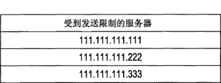
In the next step S1303, it is determined whether transmission of the image data should be restricted based on the transmission destination information obtained in step S1302. Note that the CPU 301 makes this determination with reference to the management table shown in fig. 14.
Fig. 14 shows a management table stored in the ROM 303. In the management table shown in fig. 14, the IP address of the server to be subjected to transmission restriction is managed as information for determining whether transmission of image data should be restricted. Note that the information managed in the management table is not necessarily an IP address, but may be any information (e.g., URL) that can identify a transmission destination.
In the case where it is determined in step S1303 that the transmission of the image data should be restricted, the flow advances to step S1304, and a message indicating that the transmission of the image data is restricted is displayed on the content display area 905 of the web browser.
Fig. 15 shows an example of the screen displayed in step S1304. As shown in fig. 15, in step S1304, a message indicating that the HTML document obtained from server 155 has a file upload function and transmission of image data is restricted is displayed.
On the other hand, in a case where it is determined in step S1303 that the transmission of the image data should not be restricted, the flow advances to step S1305, and the screen shown in fig. 11 is displayed in the content display area 905. In the following step S1306, transmission processing of image data is executed, and then the processing ends.
Next, the transmission processing of the image data in step S1306 in fig. 13 will be explained with reference to fig. 16. Fig. 16 is a flowchart showing a procedure of transmission processing of image data executed by the CPU 301 of the image processing apparatus 110.
First, in step S1601, it is determined for the screen shown in fig. 11 whether one of the "scan" button 1104 is pressed or the "select from bin" button 1105 is pressed. In a case where it is determined that the "select from box" button 1105 is pressed, the process proceeds to step S1602, and a box menu screen is displayed.
Fig. 17 shows an example of a box menu screen. The box selection field 1702 displays information (box number, box name assigned to a box) on each line relating to one box. When the user selects one of the rows, a screen displaying a list of documents stored in the selected box is displayed. When the scroll button 1703 or 1704 is pressed, the range of the box displayed in the box selection bar is changed. When the cancel button 1701 is pressed, the processing is stopped, and the screen returns to the screen in fig. 11.
In the screen shown in fig. 17, in a case where one of the bins is selected (yes in step S1603), the flow advances to step S1604, and a document menu screen is displayed.
Fig. 18 shows an example of a document menu screen in which a cancel button 1801, a document selection field 1802, scroll buttons 1803 and 1804, and a return button 1805 are displayed.
The document selection field 1802 displays information (document type, document name, paper size, number of pages, storage date/time, and the like) about the documents stored in the selected box in one row for each document. When the user selects one line thereof, the selected document is determined as a transmission document, and the screen returns to the screen in fig. 11. In this case, with the screen shown in fig. 11, the "select from box" button 1105 is displayed in reverse, whereby the user can recognize that a document has been selected from the box. Note that the document determined as the transmission document may be stored in the temporary area of the HDD 304.
When scroll buttons 1803 and 1804 are pressed, the range of the document displayed in the document selection field 1802 is changed. A button 1805 is a return button, and the screen returns to the screen in fig. 17. When the cancel button 1801 is pressed, the processing is stopped, and the screen returns to the screen in fig. 11.
On the other hand, in the case where it is determined in step S1601 that the "scan" button 1104 is pressed, the flow advances to step S1606, where a scan parameter such as the reading resolution is received from the user.
In the following step S1607, it is determined whether the start key 505 is pressed, and in the case where it is determined that the start key 505 is pressed, the flow advances to step S1608, the scanner 113 is operated, and the original is read.
Further, in step S1609, image data is generated based on the image on the read document, and in step S1610, the generated image data is stored in the temporary area of the HDD 304, and the screen returns to the screen shown in fig. 11. In this case, in the screen shown in fig. 11, the "scan" button 1104 is displayed in reverse, whereby the user can recognize that the image data input from the scanner 113 is stored.
In step S1611, it is determined whether the user has instructed transmission of the image data. Specifically, in the case where the send button 1103 is pressed in the screen shown in fig. 11, it is determined that the user has instructed sending of the image data.
In the case where transmission of the image data is instructed, in the following step S1612, the document selected in step S1605 or the document stored in the temporary area in step S1610 is transmitted to the server 155.
Therefore, according to the first embodiment, in the case where a web page in which a general form for requesting file upload is described is obtained from an ASP, it is possible to restrict transmission of image data according to a transmission destination of the image data. Therefore, information leakage can be prevented.
Second embodiment
Next, a second embodiment of the present invention will be explained with reference to fig. 19. Fig. 19 is a flowchart illustrating a procedure of transmission processing of image data performed by the CPU 301 of the image processing apparatus 110 relating to the second embodiment of the present invention. A process of transmitting image data based on an HTML document obtained from the server 155 in which a form containing an INPUT element in the "file" type is described will be explained. Note that the structure of the second embodiment is the same as that of the first embodiment except for the processing in fig. 19, so a description thereof is omitted here.
First, in step S1901, the CPU 301 determines whether a form for requesting input of image data is described in a document obtained from the server 155. Specifically, in a case where it is recognized that a form containing an INPUT element of the "file" type is described in the HTML document, the CPU 301 determines the form in which the INPUT of image data is requested.
In the case where it is determined in step S1901 that the form requesting input of image data is not described, the flow advances to step S1913 to display a normal screen based on the described HTML document.
On the other hand, in a case where it is determined in step S1901 that the form in which the input of the image data is requested is described, the user ID of the user who operates the image processing apparatus 110 is obtained in step S1902. The obtained user ID is the user ID input in the login screen shown in fig. 20 before the user starts operating the image processing apparatus 110. The CPU 301 recognizes the user who operates the image processing apparatus 110 based on the user ID.
In the following step S1903, similarly to step S1302 in fig. 13, information of the transmission destination of the input image data is obtained.
Further, in step S1904, it is determined whether or not transmission of the image data should be restricted based on the user ID obtained in step S1902 and the transmission destination information obtained in step S1903. Note that the CPU 301 here makes the determination with reference to the management table shown in fig. 21.
Fig. 21 shows a management table stored in the ROM 303. With the management table shown in fig. 21, a server in which transmission of image data is to be restricted is associated with and managed by various users who operate the image processing apparatus 110. Further, in the case where transmission of image data is restricted, information indicating the restricted range is managed in the management table shown in fig. 21.
In the example shown in fig. 21, for example, for user a, transmission of both image data input from the scanner 113 and image data read and input from the box is restricted for the server 111.111.111.111. Also, for user B, transmission of image data input from the scanner 113 is restricted for the server 111.111.111.222, and transmission of image data read and input from the box is not restricted.
In the case where it is determined in step S1904 that the transmission of the image data should not be restricted, the flow advances to step S1911, where the screen shown in fig. 11 is displayed on the content display area 905 of the web browser, similarly to step S1305 in fig. 13. Also, in the following step S1912, similarly to step S1306 in fig. 13, the transmission process is executed, and then the flow ends.
On the other hand, in a case where it is determined in step S1904 that transmission of the image data should be restricted, the process proceeds to step S1905, where the range of transmission restriction is determined. In the case where it is determined that the limited range is "all", the flow proceeds to step S1906, and a message indicating that the transmission of the image data is limited is displayed on the content display area 905 of the web browser, similarly to step S1304 in fig. 13.
On the other hand, in the case where it is determined in step S1905 that the limited range is a box, the flow advances to step S1907, and a screen shown in fig. 22 is displayed instead of the screen shown in fig. 11. In contrast to the screen shown in fig. 11, it can be seen that the "select from box" button is not displayed on the screen shown in fig. 22. This is because, in the determination in step S1905, it is determined that transmission of the image data read from the box and input is limited.
In the following step S1908, similar to step S1306 in fig. 13, the transmission processing of the image data is performed. Note that the "select from bin" button is not displayed, and therefore in step S1601 in fig. 16, a determination is not made that the "select from bin" button is pressed.
On the other hand, in the case where it is determined in step S1905 that the limited range is the scanner, the flow advances to step S1909, and a screen shown in fig. 23 is displayed instead of the screen shown in fig. 11. In contrast to the screen shown in fig. 11, it can be seen that the "scan" button is not displayed on the screen shown in fig. 23. This is because, in the determination in step S1905, a determination is made that transmission of the image data input from the scanner 113 is restricted.
In the following step S1910, similar to step S1306 in fig. 13, a transmission process of image data is performed. Note that the "scan" button is not displayed, and therefore in step S1601 in fig. 16, a determination is not made that the "scan" button is pressed.
Therefore, according to the second embodiment, in the case where a web page in which a general form for requesting file upload is described is obtained from an ASP, it is possible to restrict transmission of image data according to a transmission destination of the image data and a user operating the image processing apparatus. Further, it is possible to determine whether transmission of image data input from each input unit should be restricted individually for each of the first input unit and the second input unit which are different from each other. Therefore, the restrictions can be individually set for each user.
Note that with the first and second embodiments described above, a description is given of the following cases: in the management tables shown in fig. 14 and 21, the IP addresses corresponding to the restricted servers are managed. However, the information managed in these management tables is not necessarily information indicating a server that is restricted, and information indicating a server whose transmission is permitted may be managed, for example. In this case, if the obtained transmission destination information is not managed in the management table, the CPU 301 determines that the transmission of the image data should be restricted.
Other embodiments
The above-described embodiments are described as examples, but the present invention can be embodied in a system, an apparatus, a method, a program, a storage medium (recording medium), or the like. Specifically, the present invention may be applied to a system constituted by a plurality of devices, or may be applied to an apparatus constituted by a single device.
Note that the present invention provides a system or an apparatus with a software program (a program corresponding to the flowchart shown in the drawing of the embodiment) that directly or remotely realizes the functions of the above-described embodiment. But also the case where the provided program code is read and executed by a computer of the system or apparatus.
Therefore, in order to realize the functional processing of the present invention by a computer, the program code itself installed in the computer also realizes the present invention. That is, the present invention includes the computer program itself for realizing the functional processing of the present invention.
In this case, if the computer program has a function of a program, the program may be in the form of object code, a program executed by an interpreter, script data supplied to an OS, or the like.
Examples of the recording medium for supplying the program include a flexible disk, a hard disk, an optical disk, a magneto-optical disk, an MO, a CD-ROM, a CD-R, CD-RW, a magnetic tape, a nonvolatile memory card, a ROM, and a DVD (DVD-ROM, DVD-R).
In addition, the program may be provided by being downloaded from a website on the internet to a recording medium such as a hard disk using a browser on a client computer. That is, the web site is accessed, and the computer program itself or the file according to the present invention, which is compressed and includes the automatic installation function, is downloaded from the web site. Further, the program code constituting the program of the present invention may be divided into a plurality of files, and each file may be downloaded from a different website. That is, a WWW server for downloading a program file to a plurality of users to realize the functional processing of the present invention with a computer is also included in the scope of the present invention.
Also, the program of the present invention is encoded and stored in a computer-readable storage medium such as a CD-ROM and distributed to users. Then, a user who satisfies a predetermined condition can download key information for decoding the code from a website via the internet. The key information here can be used to execute the encoded program, thereby being installed on a computer and executed.
Further, the computer executes the read program, whereby the functions of the above-described embodiments can be realized. In addition, based on the program instructions, an OS or the like operating on the computer can perform part or all of the actual processing, whereby the functions of the above-described embodiments can be realized by such processing.
Further, the functions of the above-described embodiments can be realized even after the program read out from the recording medium is written into a memory provided on a function expansion board inserted into the computer or a function expansion unit connected to the computer. That is, based on its program instructions, the functions of the above-described embodiments can be realized by performing part or all of the actual processing by the CPU provided with the function expansion board or the function expansion unit.
While the present invention has been described with reference to exemplary embodiments, it is to be understood that the invention is not limited to the disclosed exemplary embodiments. The scope of the following claims is to be accorded the broadest interpretation so as to encompass all such modifications and equivalent structures and functions.
Claims (9)
1. An image processing apparatus which has an input unit configured to input image data and which is communicably connected to a plurality of external apparatuses via a network, comprising:
an obtaining unit configured to obtain a document in which a predetermined form is described from one of the plurality of external devices via the network;
an identifying unit configured to identify that the predetermined form described in the document obtained by the obtaining unit is a form for requesting input of image data;
a transmission unit configured to transmit the image data input by the input unit according to an instruction from a user based on the predetermined form;
a determination unit configured to determine whether transmission of the image data should be restricted according to a transmission destination of the image data transmitted by the transmission unit, in a case where the recognition unit recognizes that the predetermined form is a form for requesting input of image data; and
a control unit configured to limit transmission of the image data by the transmission unit based on a determination result of the determination unit.
2. The image processing apparatus according to claim 1, further comprising:
a display unit configured to display a screen corresponding to the document obtained by the obtaining unit; wherein,
the input unit inputs image data according to an instruction from the user via the screen displayed by the display unit.
3. The image processing apparatus according to claim 2, wherein the control unit, in a case where the determination unit determines that the transmission of the image data is restricted, causes the display unit to display a message indicating that the transmission of the image data is restricted if the display unit displays a screen corresponding to the obtained document.
4. The image processing apparatus according to claim 1, further comprising:
a holding unit configured to hold information indicating a transmission destination for restricting the transmission of the image data by the transmission unit; wherein,
the determination unit makes the determination based on the information held by the holding unit.
5. The image processing apparatus according to claim 1, further comprising:
an identification unit configured to identify a user; wherein,
the determination unit makes the determination according to an external device serving as a transmission destination of the image data to be transmitted, and according to the user recognized by the recognition unit.
6. The image processing apparatus according to claim 1, further comprising:
a reading unit configured to read an image on an original and output image data; wherein,
the input unit inputs the image data output by the reading unit.
7. The image processing apparatus according to claim 1,
the input unit includes at least a first input unit and a second input unit different from each other, and wherein,
the determination unit independently determines whether transmission of the image data input by the first input unit is restricted and whether transmission of the image data input by the second input unit is restricted.
8. The image processing apparatus according to claim 1, wherein the external apparatus is a web server;
and wherein the document obtained by the obtaining unit is an HTML document provided by the web server;
and wherein the display unit is a web browser configured to analyze an HTML document provided from the web server and display a screen based on the HTML document.
9. A control method of an image processing apparatus which has an input unit configured to input image data and which is communicably connected to a plurality of external apparatuses via a network, comprising:
an obtaining process configured to obtain a document in which a predetermined form is described from one of the plurality of external apparatuses via the network;
an identification process configured to identify that the predetermined form described in the document obtained by the obtaining process is a form for requesting input of image data;
a transmission process configured to transmit the image data input by the input unit in accordance with an instruction from a user based on the predetermined form;
a determination process configured to determine whether or not transmission of the image data should be restricted according to a transmission destination of the image data transmitted in the transmission process in a case where the recognition process recognizes that the predetermined form is a form for requesting input of image data; and
a control process configured to restrict transmission of the image data in the transmission process based on a determination result in the determination process.
Applications Claiming Priority (3)
| Application Number | Priority Date | Filing Date | Title |
|---|---|---|---|
| JP2007328727A JP5064994B2 (en) | 2007-12-20 | 2007-12-20 | Image processing apparatus, control method therefor, and program |
| JP2007-328727 | 2007-12-20 | ||
| JP2007328727 | 2007-12-20 |
Publications (2)
| Publication Number | Publication Date |
|---|---|
| CN101465929A true CN101465929A (en) | 2009-06-24 |
| CN101465929B CN101465929B (en) | 2013-08-14 |
Family
ID=40806276
Family Applications (1)
| Application Number | Title | Priority Date | Filing Date |
|---|---|---|---|
| CN200810185864XA Expired - Fee Related CN101465929B (en) | 2007-12-20 | 2008-12-18 | Image processing apparatus and control method thereof |
Country Status (3)
| Country | Link |
|---|---|
| US (1) | US8384934B2 (en) |
| JP (1) | JP5064994B2 (en) |
| CN (1) | CN101465929B (en) |
Cited By (4)
| Publication number | Priority date | Publication date | Assignee | Title |
|---|---|---|---|---|
| CN101998016A (en) * | 2009-08-21 | 2011-03-30 | 株式会社理光 | Image forming apparatus, image processing apparatus, image processing system, image processing method, program, and recording medium |
| CN105786161A (en) * | 2012-04-18 | 2016-07-20 | 佳能株式会社 | Information Processing Apparatus And Control Method Thereof |
| CN105938470A (en) * | 2015-03-02 | 2016-09-14 | 佳能株式会社 | Information processing system, server apparatus, control method |
| CN109471986A (en) * | 2017-06-07 | 2019-03-15 | 夏普株式会社 | Document management apparatus, compounding machine, file management method and program |
Families Citing this family (5)
| Publication number | Priority date | Publication date | Assignee | Title |
|---|---|---|---|---|
| US6108637A (en) * | 1996-09-03 | 2000-08-22 | Nielsen Media Research, Inc. | Content display monitor |
| JP2008109380A (en) * | 2006-10-25 | 2008-05-08 | Media Exchange Inc | Electronic mail transmission and reception system |
| JP2010068455A (en) * | 2008-09-12 | 2010-03-25 | Kyocera Mita Corp | Display control apparatus, image forming apparatus, and display control program |
| JP7212844B2 (en) * | 2019-01-04 | 2023-01-26 | コニカミノルタ株式会社 | Image forming device and program |
| CN115499156B (en) * | 2022-07-29 | 2024-06-07 | 天翼云科技有限公司 | Website backend information leakage detection method, electronic device and storage medium |
Family Cites Families (7)
| Publication number | Priority date | Publication date | Assignee | Title |
|---|---|---|---|---|
| JP2002077504A (en) | 2000-08-28 | 2002-03-15 | Kyocera Mita Corp | Push scanner device and use therefor |
| JP4819311B2 (en) | 2003-11-18 | 2011-11-24 | キヤノン株式会社 | Image processing apparatus, control method thereof, and program |
| JP2006197241A (en) * | 2005-01-13 | 2006-07-27 | Kanden System Solutions Co Ltd | Mail sending system |
| JP4455357B2 (en) * | 2005-01-28 | 2010-04-21 | キヤノン株式会社 | Information processing apparatus and information processing method |
| JP4174480B2 (en) * | 2005-02-21 | 2008-10-29 | キヤノン株式会社 | Data transmitting apparatus, control method therefor, and image reading apparatus using the same |
| JP2007067807A (en) * | 2005-08-31 | 2007-03-15 | Canon Inc | Data transmission device, data transmission method and program |
| JP4911940B2 (en) | 2005-09-30 | 2012-04-04 | キヤノン株式会社 | Data transmission apparatus, control method therefor, and image input / output apparatus |
-
2007
- 2007-12-20 JP JP2007328727A patent/JP5064994B2/en not_active Expired - Fee Related
-
2008
- 2008-12-18 US US12/338,689 patent/US8384934B2/en not_active Expired - Fee Related
- 2008-12-18 CN CN200810185864XA patent/CN101465929B/en not_active Expired - Fee Related
Cited By (10)
| Publication number | Priority date | Publication date | Assignee | Title |
|---|---|---|---|---|
| CN101998016A (en) * | 2009-08-21 | 2011-03-30 | 株式会社理光 | Image forming apparatus, image processing apparatus, image processing system, image processing method, program, and recording medium |
| CN101998016B (en) * | 2009-08-21 | 2013-02-06 | 株式会社理光 | Image forming apparatus, image processing apparatus, system and method |
| US9019527B2 (en) | 2009-08-21 | 2015-04-28 | Ricoh Company, Ltd | Image forming apparatus, image processing apparatus, image processing system, image processing method, program, and recording medium |
| CN105786161A (en) * | 2012-04-18 | 2016-07-20 | 佳能株式会社 | Information Processing Apparatus And Control Method Thereof |
| CN105786161B (en) * | 2012-04-18 | 2018-12-21 | 佳能株式会社 | Printing equipment and its control method |
| US11307633B2 (en) | 2012-04-18 | 2022-04-19 | Canon Kabushiki Kaisha | Information processing apparatus, control method thereof, and storage medium |
| CN105938470A (en) * | 2015-03-02 | 2016-09-14 | 佳能株式会社 | Information processing system, server apparatus, control method |
| US10353999B2 (en) | 2015-03-02 | 2019-07-16 | Canon Kabushiki Kaisha | Information processing system, server apparatus, control method, and storage medium |
| CN105938470B (en) * | 2015-03-02 | 2020-03-03 | 佳能株式会社 | Information processing system, server device, and control method |
| CN109471986A (en) * | 2017-06-07 | 2019-03-15 | 夏普株式会社 | Document management apparatus, compounding machine, file management method and program |
Also Published As
| Publication number | Publication date |
|---|---|
| JP5064994B2 (en) | 2012-10-31 |
| US8384934B2 (en) | 2013-02-26 |
| US20090251738A1 (en) | 2009-10-08 |
| JP2009152848A (en) | 2009-07-09 |
| CN101465929B (en) | 2013-08-14 |
Similar Documents
| Publication | Publication Date | Title |
|---|---|---|
| US10026029B2 (en) | Image processing apparatus, and control method, and computer-readable storage medium thereof | |
| CN101465929B (en) | Image processing apparatus and control method thereof | |
| US7464333B2 (en) | Image processing apparatus, and method for controlling the image processing apparatus to process displayable and non-displayable data received from a server | |
| JP4819311B2 (en) | Image processing apparatus, control method thereof, and program | |
| US20090164927A1 (en) | Image processing apparatus and method thereof | |
| US8356084B2 (en) | Information processing apparatus and image processing apparatus | |
| JP4745866B2 (en) | Device management system and control method thereof | |
| US10848629B2 (en) | Image processing apparatus, image processing system, image processing method, and web browser program | |
| US20100208300A1 (en) | Image processing apparatus, server apparatus, control method therefor, and storage medium | |
| US20060268334A1 (en) | Data processing apparatus connectable to network, and control method therefor | |
| US8823980B2 (en) | Printing system, image forming apparatus, data generation apparatus, storage apparatus, and control method | |
| JP4500718B2 (en) | Information processing apparatus, image processing apparatus, remote operation system and control method thereof | |
| US8125668B2 (en) | Information processing device, image processing device, job processing method, and storage medium | |
| JP2008211747A (en) | Image processing apparatus, server apparatus, task processing method, storage medium, and program | |
| JP2012243286A (en) | Information processing device, document data update method and computer program | |
| US20220377188A1 (en) | Image processing apparatus, server, system, controlling method and storage medium therefor | |
| JP2006163707A (en) | Image forming system |
Legal Events
| Date | Code | Title | Description |
|---|---|---|---|
| C06 | Publication | ||
| PB01 | Publication | ||
| C10 | Entry into substantive examination | ||
| SE01 | Entry into force of request for substantive examination | ||
| C14 | Grant of patent or utility model | ||
| GR01 | Patent grant | ||
| CF01 | Termination of patent right due to non-payment of annual fee | ||
| CF01 | Termination of patent right due to non-payment of annual fee |
Granted publication date: 20130814 Termination date: 20191218 |