CN101420814A - Multichannel lamp light control system and method - Google Patents
Multichannel lamp light control system and method Download PDFInfo
- Publication number
- CN101420814A CN101420814A CNA2007102022202A CN200710202220A CN101420814A CN 101420814 A CN101420814 A CN 101420814A CN A2007102022202 A CNA2007102022202 A CN A2007102022202A CN 200710202220 A CN200710202220 A CN 200710202220A CN 101420814 A CN101420814 A CN 101420814A
- Authority
- CN
- China
- Prior art keywords
- channel
- light brightness
- computer
- controller
- data information
- Prior art date
- Legal status (The legal status is an assumption and is not a legal conclusion. Google has not performed a legal analysis and makes no representation as to the accuracy of the status listed.)
- Pending
Links
Images


Classifications
-
- H—ELECTRICITY
- H03—ELECTRONIC CIRCUITRY
- H03M—CODING; DECODING; CODE CONVERSION IN GENERAL
- H03M1/00—Analogue/digital conversion; Digital/analogue conversion
- H03M1/66—Digital/analogue converters
- H03M1/662—Multiplexed conversion systems
-
- H—ELECTRICITY
- H05—ELECTRIC TECHNIQUES NOT OTHERWISE PROVIDED FOR
- H05B—ELECTRIC HEATING; ELECTRIC LIGHT SOURCES NOT OTHERWISE PROVIDED FOR; CIRCUIT ARRANGEMENTS FOR ELECTRIC LIGHT SOURCES, IN GENERAL
- H05B47/00—Circuit arrangements for operating light sources in general, i.e. where the type of light source is not relevant
- H05B47/10—Controlling the light source
- H05B47/175—Controlling the light source by remote control
- H05B47/18—Controlling the light source by remote control via data-bus transmission
-
- H—ELECTRICITY
- H05—ELECTRIC TECHNIQUES NOT OTHERWISE PROVIDED FOR
- H05B—ELECTRIC HEATING; ELECTRIC LIGHT SOURCES NOT OTHERWISE PROVIDED FOR; CIRCUIT ARRANGEMENTS FOR ELECTRIC LIGHT SOURCES, IN GENERAL
- H05B47/00—Circuit arrangements for operating light sources in general, i.e. where the type of light source is not relevant
- H05B47/10—Controlling the light source
- H05B47/175—Controlling the light source by remote control
- H05B47/196—Controlling the light source by remote control characterised by user interface arrangements
Landscapes
- Engineering & Computer Science (AREA)
- Theoretical Computer Science (AREA)
- Circuit Arrangement For Electric Light Sources In General (AREA)
Abstract
一种多通道灯光控制方法,该方法包括步骤:设置计算机及控制器的通讯参数;计算机接收用户输入的灯光亮度数据信息;发送灯光亮度数据信息给控制器;控制器接收并处理灯光亮度数据信息,产生灯光亮度数字信号及编码地址;将灯光亮度数字信号及编码地址发送给数字/模拟转换器;数字/模拟转换器将灯光亮度数字信号转换成灯光亮度模拟信号,并根据编码地址将该灯光亮度模拟信号输出给相应通道的功率放大器;及功率放大器对灯光亮度模拟信号进行放大并控制相应通道灯光电路中的灯光亮度。本发明采用基于控制器控制的两级控制系统,可以对多通道灯光进行亮度调节,结构简洁,安全性高。
A multi-channel lighting control method, the method includes the steps of: setting the communication parameters of the computer and the controller; the computer receiving the lighting brightness data information input by the user; sending the lighting brightness data information to the controller; the controller receiving and processing the lighting brightness data information , to generate the digital signal of light brightness and coded address; send the digital signal of light brightness and coded address to the digital/analog converter; The brightness analog signal is output to the power amplifier of the corresponding channel; and the power amplifier amplifies the light brightness analog signal and controls the light brightness in the light circuit of the corresponding channel. The invention adopts a two-level control system based on controller control, can adjust the brightness of multi-channel lights, has simple structure and high safety.
Description
技术领域 technical field
本发明涉及一种多通道灯光控制系统及方法。The invention relates to a multi-channel lighting control system and method.
背景技术 Background technique
灯光控制在精密测量中起着非常重要的作用,其控制效果直接影响测量的精度。现有影像量测机台的灯光控制系统最多能对八个通道的灯光进行调节,在通道的选择及亮度调节方面存在缺陷,难以对一些复杂的零件进行测量。参阅图1所示,为现有灯光控制系统的架构图,该灯光控制系统系统包括计算机1、单片机2、数字/模拟信号转换器31、32、33及功率放大器41、42、43。数字/模拟信号转换器31、32、33分别与功率放大器41、42、43串联,用于控制灯光电路51、52、53的亮度调节。图1的灯光控制系统有三组数字/模拟信号转换器与功率放大器串联电路,可以控制三个通道的灯光,若增加通道数目,必须增加相应的数字/模拟信号转换器与功率放大器串联电路。现有灯光控制系统的通道数目有限,且增加通道时灯光控制系统的成本和体积相应增加。Lighting control plays a very important role in precision measurement, and its control effect directly affects the accuracy of measurement. The lighting control system of the existing image measuring machine can adjust the lighting of eight channels at most, but there are defects in channel selection and brightness adjustment, and it is difficult to measure some complex parts. Referring to FIG. 1 , it is a structure diagram of an existing lighting control system. The lighting control system includes a computer 1 , a single-chip microcomputer 2 , digital/
发明内容 Contents of the invention
鉴于以上内容,有必要提出一种能够对多个通道灯光进行亮度调节的多通道灯光控制系统及方法。In view of the above, it is necessary to propose a multi-channel lighting control system and method capable of adjusting the brightness of multiple channels of lighting.
一种多通道灯光控制系统,包括计算机与多个功率放大器,所述计算机用于接收及发送用户设置的各个通道的灯光亮度数据信息,所述多个功率放大器用于控制多个通道灯光电路的亮度调节,该系统还包括:控制器,与计算机相连,用于接收及处理计算机发送的各个通道的灯光亮度数据信息,产生各个通道的灯光亮度数字信号及各个通道的编码地址;及数字/模拟转换器,该数字/模拟转换器与控制器及多个功率放大器相连,用于接收控制器产生的各个通道的灯光亮度数字信号及各个通道的编码地址,将所接收的各个通道的灯光亮度数字信号转换成各个通道的灯光亮度模拟信号,并根据所接收的各个通道的编码地址将该各个通道的灯光亮度模拟信号发送给相应通道的功率放大器,以控制各个通道灯光电路的亮度调节。A multi-channel lighting control system, including a computer and multiple power amplifiers, the computer is used to receive and send the light brightness data information of each channel set by the user, and the multiple power amplifiers are used to control the lighting circuits of multiple channels Brightness adjustment, the system also includes: a controller, connected to the computer, used to receive and process the light brightness data information of each channel sent by the computer, generate digital signals of the light brightness of each channel and the encoding address of each channel; and digital/analog Converter, the digital/analog converter is connected with the controller and multiple power amplifiers, used to receive the digital signal of the light brightness of each channel and the coded address of each channel generated by the controller, and convert the received light brightness digital signal of each channel to The signal is converted into the light brightness analog signal of each channel, and the light brightness analog signal of each channel is sent to the power amplifier of the corresponding channel according to the received coded address of each channel, so as to control the brightness adjustment of the light circuit of each channel.
一种多通道灯光控制方法,包括如下步骤:设置计算机及控制器的通讯参数;计算机接收用户输入的各个通道的灯光亮度数据信息;计算机发送各个通道的灯光亮度数据信息给控制器;控制器接收并处理各个通道的灯光亮度数据信息,产生各个通道的灯光亮度数字信号及各个通道的编码地址;控制器将各个通道的灯光亮度数字信号及各个通道的编码地址发送给数字/模拟转换器;数字/模拟转换器将所接收的各个通道的灯光亮度数字信号转换成各个通道的灯光亮度模拟信号,并根据所接收的各个通道的编码地址将该各个通道的灯光亮度模拟信号输出给相应通道的功率放大器;及各个通道的功率放大器对相应通道的灯光亮度模拟信号进行放大并控制相应通道灯光电路中的灯光亮度。A multi-channel light control method, comprising the following steps: setting communication parameters of a computer and a controller; the computer receiving the light brightness data information of each channel input by the user; the computer sending the light brightness data information of each channel to the controller; the controller receiving And process the light brightness data information of each channel to generate the digital signal of light brightness of each channel and the code address of each channel; the controller sends the digital signal of light brightness of each channel and the code address of each channel to the digital/analog converter; The /analog converter converts the received digital signal of light brightness of each channel into the analog signal of light brightness of each channel, and outputs the analog signal of light brightness of each channel to the power of the corresponding channel according to the received encoding address of each channel amplifier; and the power amplifier of each channel amplifies the light brightness analog signal of the corresponding channel and controls the light brightness in the light circuit of the corresponding channel.
本发明多通道灯光控制系统及方法,采用基于控制器控制的两级控制系统,可以对多通道灯光进行亮度调节;本发明多个通道共用一个数字/模拟转换器,精简了系统结构,节约了成本。The multi-channel lighting control system and method of the present invention adopts a two-level control system based on controller control, which can adjust the brightness of multi-channel lighting; multiple channels of the present invention share a digital/analog converter, which simplifies the system structure and saves cost.
附图说明 Description of drawings
图1为现有灯光控制系统的方框图。Figure 1 is a block diagram of an existing lighting control system.
图2为本发明多通道灯光控制系统的方框图。Fig. 2 is a block diagram of the multi-channel lighting control system of the present invention.
图3为本发明多通道灯光控制系统的流程图。Fig. 3 is a flow chart of the multi-channel lighting control system of the present invention.
图4为图3中步骤S303的详细流程图。FIG. 4 is a detailed flowchart of step S303 in FIG. 3 .
具体实施方式 Detailed ways
参阅图2所示,为本发明多通道灯光控制系统较佳实施例的方框图。在本较佳实施例中,以16通道灯光控制系统为例进行说明。Referring to FIG. 2 , it is a block diagram of a preferred embodiment of the multi-channel lighting control system of the present invention. In this preferred embodiment, a 16-channel lighting control system is taken as an example for illustration.
该多通道灯光控制系统包括计算机1、控制器2、数字/模拟(Digital/Analog,D/A)转换器3、功率放大器401、402、……、416。功率放大器401控制通道1,功率放大器402控制通道2,……,功率放大器416控制通道16。The multi-channel lighting control system includes a computer 1 , a controller 2 , a digital/analog (D/A) converter 3 , and
计算机1是用户进行灯光控制的接口设备,该计算机1主要实现三个功能:提供用户界面,接收用户的验证码及用户设置的各个通道的灯光亮度数据信息;与控制器2通讯,将用户的验证码及用户设置的各个通道的灯光亮度数据信息发送给控制器2;显示系统运行过程中的各种错误提示,错误提示包括串口设置错误提示、非法用户提示及数据传输错误提示。验证码用于对用户进行合法性验证,用户仅当输入正确的验证码并经控制器2验证为合法用户后才能控制多通道灯光。The computer 1 is the interface device for the user to control the lighting. The computer 1 mainly realizes three functions: providing the user interface, receiving the verification code of the user and the light brightness data information of each channel set by the user; communicating with the controller 2, and transferring the user's The verification code and the light brightness data information of each channel set by the user are sent to the controller 2; various error prompts during the operation of the system are displayed, and the error prompts include serial port setting error prompts, illegal user prompts and data transmission error prompts. The verification code is used to verify the legitimacy of the user, and the user can control the multi-channel lighting only after entering the correct verification code and being verified as a legitimate user by the controller 2.
所述的控制器2可以是单片机、数字信号处理器(DSP)、可编程控制器(PLC),也可以是其他适用的控制元件,以下以单片机为例进行说明。The controller 2 may be a single-chip microcomputer, a digital signal processor (DSP), a programmable logic controller (PLC), or other applicable control elements. The following uses a single-chip microcomputer as an example for illustration.
单片机通过RS232串口与计算机1连接,用于接收用户的验证码及用户设置的各个通道的灯光亮度数据信息,根据所接受的验证码进行用户合法性验证,并处理用户设置的各个通道的灯光亮度数据信息,产生各个通道的灯光亮度数字信号及各个通道的编码地址。通道的编码地址为通道的二进制编码,本实施例用四位二进制数表示,0000表示通道1,0001表示通道2,……,1111表示通道16,所述的0000、0001、……、1111即为通道的编码地址。The single-chip microcomputer is connected to the computer 1 through the RS232 serial port, and is used to receive the user's verification code and the light brightness data information of each channel set by the user, perform user legality verification according to the accepted verification code, and process the light brightness of each channel set by the user The data information generates the digital signal of light brightness of each channel and the encoding address of each channel. The coded address of the channel is the binary code of the channel. In this embodiment, it is represented by a four-digit binary number. 0000 indicates channel 1, 0001 indicates channel 2, ..., 1111 indicates channel 16, and the 0000, 0001, ..., 1111 are is the encoded address of the channel.
为实现计算机1与单片机的通讯,首先应将计算机1与单片机的串口参数设置为一致,该串口参数包括波特率、数据位、停止位及校验位等。In order to realize the communication between the computer 1 and the single-chip microcomputer, firstly, the serial port parameters of the computer 1 and the single-chip microcomputer should be set to be consistent, and the serial port parameters include baud rate, data bit, stop bit and parity bit, etc.
D/A转换器3与单片机及功率放大器401、402、……、416相连。该D/A转换器3用于接收单片机发出的各个通道的灯光亮度数字信号及各个通道的编码地址,将该各个通道的灯光亮度数字信号转换成各个通道的灯光亮度模拟信号,根据该各个通道的编码地址将该各个通道的灯光亮度模拟信号输出给相应通道的功率放大器401、402、……、或416。例如D/A转换器3接收到灯光亮度数字信号00011111及编码地址0000(通道1的编码地址),则D/A转换器3将灯光亮度数字信号00011111转换为灯光亮度模拟信号,并将该灯光亮度模拟信号输出给功率放大器401(控制通道1)。本实施例中16个通道共用一个D/A转换器3,该D/A转换器3有16个输出口,分别连接16个功率放大器401、402、……、416。若要控制更多通道,只需相应增加D/A转换器3及相关电路。本实施例选用8位的D/A转换器。The D/A converter 3 is connected with the single chip microcomputer and the
功率放大器401、402、……、416分别与灯光电路501、502、……、516串联,用于放大各个通道的灯光亮度模拟信号并控制各个通道灯光电路。每个功率放大器中有一个三极管,该三极管既有电流放大的作用,又有作为灯光电路的开关元件以开通和断开灯光电路中电流的作用。The
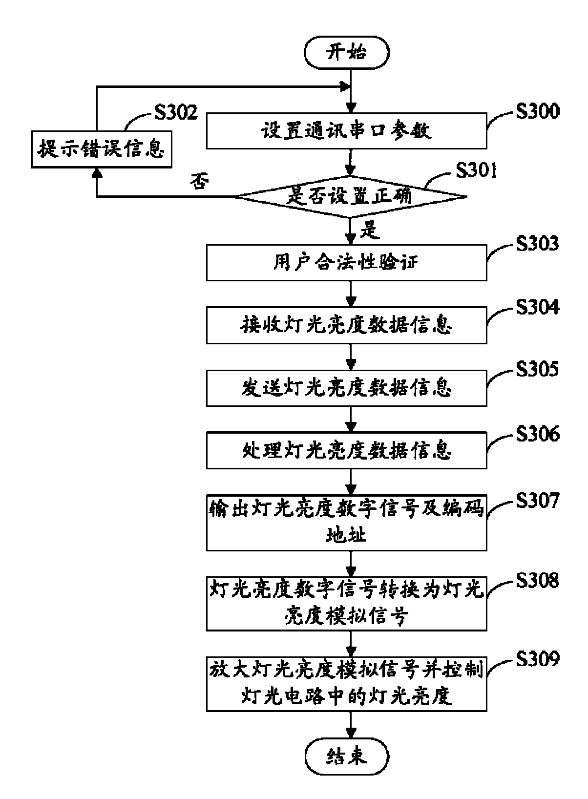
参阅图3所示,是本发明多通道灯光控制方法的流程图。Referring to FIG. 3 , it is a flow chart of the multi-channel lighting control method of the present invention.
步骤S300,设置计算机1及单片机的通讯串口参数。计算机1的串口参数包括串口号、波特率、数据位、停止位和校验位等,单片机的串口参数包括波特率、数据位、停止位和校验位等。Step S300, setting the communication serial port parameters of the computer 1 and the single-chip microcomputer. The serial port parameters of computer 1 include serial port number, baud rate, data bit, stop bit and check bit, etc., and the serial port parameters of the single-chip microcomputer include baud rate, data bit, stop bit and check bit, etc.
步骤S301,计算机1判断串口是否设置正确。In step S301, the computer 1 judges whether the serial port is set correctly.
步骤S302,若串口设置错误,则在计算机1的用户界面上反馈错误信息给用户并返回步骤S300。串口设置错误可能为步骤S300中串口号、波特率、数据位、停止位或校验位的设置错误,例如所设置的串口已被占用,或波特率不是合法的数值。Step S302, if the serial port setting is wrong, feed back an error message to the user on the user interface of the computer 1 and return to step S300. The serial port setting error may be the setting error of the serial port number, baud rate, data bit, stop bit or parity bit in step S300, for example, the set serial port is already occupied, or the baud rate is not a legal value.
步骤S303,若串口设置正确,则进行用户合法性验证。该步骤的详细流程在图4中进行说明。In step S303, if the serial port setting is correct, user legitimacy verification is performed. The detailed flow of this step is illustrated in FIG. 4 .
步骤S304,若是合法用户,则计算机1接收用户输入的各个通道的灯光亮度数据信息。本实施例可实现各个通道的灯光亮度数据信息的手动及自动输入。手动输入是用户利用鼠标移动亮度滑块的位置,或是利用键盘输入灯光亮度的具体数值,还可以是其他适用的方式。自动输入是通过量测软件设定灯光亮度后调用软件接口来实现。假定灯光亮度数据信息为0~255之间的整数,则用户输入的合法的灯光亮度数据信息为0~255之间的整数,亮度滑块的位置也表示0~255之间的整数。Step S304, if it is a legitimate user, the computer 1 receives the light brightness data information of each channel input by the user. This embodiment can realize manual and automatic input of light brightness data information of each channel. The manual input is that the user uses the mouse to move the position of the brightness slider, or uses the keyboard to input the specific value of the light brightness, or other applicable methods. Automatic input is realized by calling the software interface after setting the brightness of the light through the measurement software. Assuming that the light brightness data information is an integer between 0 and 255, the legal light brightness data information entered by the user is an integer between 0 and 255, and the position of the brightness slider also represents an integer between 0 and 255.
步骤S305,计算机1通过串口发送各个通道的灯光亮度数据信息给单片机。本实施例中计算机1发送16个通道的灯光亮度数据信息给单片机。In step S305, the computer 1 sends the light brightness data information of each channel to the single-chip microcomputer through the serial port. In this embodiment, the computer 1 sends the light brightness data information of 16 channels to the single-chip microcomputer.
步骤S306,单片机接收并处理各个通道的灯光亮度数据信息,产生各个通道的灯光亮度数字信号及各个通道的编码地址。Step S306, the single-chip microcomputer receives and processes the light brightness data information of each channel, and generates the light brightness digital signal of each channel and the coded address of each channel.
单片机内有只读存储区,各个级别灯光亮度所对应的灯光亮度数字信号预先储存在该只读存储区中。本实施例把灯光亮度分为0~255共256个级别,一个级别的灯光亮度存储在该只读存储区中的一个存储单元,每一个存储单元为一个字节,如地址0x0100存储0级亮度的灯光亮度数字信号00000000,0x0101存储1级亮度的灯光亮度数字信号00000001,……,0x01FF存储255级亮度的灯光亮度数字信号11111111。考虑到低级别的亮度(如1级、2级亮度)在经过D/A转换及功率放大后不能开通灯光电路501、502、……、516的电流,而用户期望其输入的灯光亮度数据信息大于0(即亮度级别大于0)时能看到灯光开通,因此在存储灯光亮度数字信号时对灯光亮度数字信号作了一个转换,如把1级亮度00000001转换为00001000,2级亮度02H转换为00001001,……,将转换后的灯光亮度数字信号存储到其对应的存储单元,使得低级别的亮度也能开通灯光电路501、502、……、516的电流。There is a read-only storage area in the single-chip microcomputer, and the digital signal of light brightness corresponding to each level of light brightness is pre-stored in the read-only storage area. In this embodiment, the light brightness is divided into 256 levels from 0 to 255. The light brightness of a level is stored in a storage unit in the read-only storage area, and each storage unit is a byte. For example, address 0x0100 stores 0-level brightness The light brightness digital signal 00000000, 0x0101 stores the light brightness digital signal 00000001 of level 1 brightness, ..., 0x01FF stores the light brightness digital signal 11111111 of 255 level brightness. Considering that the low-level brightness (such as level 1 and level 2 brightness) cannot turn on the current of the
单片机接收到计算机1输出的各个通道的灯光亮度数据信息后,依次将所接收的各个通道的的灯光亮度数据信息转换成该只读存储区中某个级别的灯光亮度的对应地址,然后取出该地址所对应的灯光亮度数字信号。例如地址0x0100存储0级亮度00000000,0x0101存储1级亮度00001000,……,0x011F存储31级亮度00011111,……,0x01FF存储255级亮度11111111,则若接收的灯光亮度数据信息是31级,单片机先找到31级亮度的存储地址0x011F,再取出0x011F中存储的灯光亮度数字信号00011111,若接收的灯光亮度数据信息是1级,单片机先找到1级亮度的存储地址0x0101,再取出0x0101中存储的灯光亮度数字信号00001000。在这一步骤中,单片机先判断所接收的数据信息是否正确,若是错误数据信息,单片机对该错误数据信息进行清零处理,不向D/A转换器3发送灯光亮度数字信号。例如合法的灯光亮度数据信息在0~255之内,若用户输入50,则对该数据进行清零处理。After receiving the light brightness data information of each channel output by the computer 1, the single-chip microcomputer sequentially converts the received light brightness data information of each channel into the corresponding address of a certain level of light brightness in the read-only storage area, and then takes out the The digital signal of light brightness corresponding to the address. For example, the address 0x0100 stores brightness level 00000000, 0x0101 stores brightness level 00001000, ..., 0x011F stores
需要说明的是,上述仅为单片机处理各个通道的灯光亮度数据信息一个例子,用户还可以选择其他方案来处理各个通道的灯光亮度数据信息。It should be noted that the above is only an example of the single chip microcomputer processing the light brightness data information of each channel, and the user can also choose other schemes to process the light brightness data information of each channel.
单片机依次处理各个通道的灯光亮度数据信息时还对各个通道进行地址编码。单片机通常有多个并行输入/输出(Input/Output,I/O)口,如P0、P1、P2及P3,每个I/O口均为8位。本实施例对16通道的灯光进行控制,只需使用P1中4位,例如选择P1的低四位输出地址编码,以二进制数0000表示通道1,0001表示通道2,……,1111表示通道16。若要控制更多通道的灯光,只需使用I/O口的更多位,如使用5位即可控制32个通道。When the single-chip microcomputer sequentially processes the light brightness data information of each channel, it also encodes the address of each channel. A single-chip microcomputer usually has multiple parallel input/output (Input/Output, I/O) ports, such as P0, P1, P2, and P3, and each I/O port is 8 bits. In this embodiment, only 4 bits in P1 are needed to control the lights of 16 channels. For example, select the output address code of the lower four bits of P1, and use binary number 0000 to represent channel 1, 0001 to represent channel 2, ..., 1111 to represent channel 16 . If you want to control lights of more channels, you only need to use more bits of the I/O port, such as using 5 bits to control 32 channels.
步骤S307,单片机将各个通道的灯光亮度数字信号及各个通道的编码地址发送给D/A转换器3。单片机发出的灯光亮度数字信号是8位的并行数据。Step S307 , the single-chip microcomputer sends the digital signal of light brightness of each channel and the coded address of each channel to the D/A converter 3 . The light brightness digital signal sent by the single chip microcomputer is 8-bit parallel data.
步骤S308,D/A转换器3将单片机发送的各个通道的灯光亮度数字信号转换成各个通道的灯光亮度模拟信号,并根据各个通道的编码地址将该各个通道的灯光亮度模拟信号输出到相应通道的功率放大器401、402、……、或416。D/A转换器3若收到编码地址0000,则将转换后的灯光亮度模拟信号输出给功率放大器401;若收到编码地址0001,则将转换后的灯光亮度模拟信号输出给功率放大器402;……;若收到编码地址1111,则将转换后的灯光亮度模拟信号输出给功率放大器416。Step S308, the D/A converter 3 converts the light brightness digital signal of each channel sent by the single chip microcomputer into the light brightness analog signal of each channel, and outputs the light brightness analog signal of each channel to the corresponding channel according to the coding address of each channel The
步骤S309,功率放大器401、402、……、416对各个通道的灯光亮度模拟信号进行放大并控制灯光电路501、502、……、516中的灯光亮度。该功率放大器401、402、……、416通过三极管放大灯光亮度模拟信号,该三极管既有电流放大的作用,又有作为灯光电路501、502、……、516的开关元件以开通和断开灯光电路501、502、……、516中电流的作用。In step S309, the
在步骤S306中,单片机接收各个通道的灯光亮度数据信息之后,还立即将所接收的各个通道的灯光亮度数据信息发送给计算机1,计算机1判断所接收的各个通道的灯光亮度数据信息与所发送的各个通道的灯光亮度数据信息是否相同,若两者不同,则在计算机1的用户界面上反馈错误信息给用户。该步骤是校验串口传输是否有错误,若数据传输过程中发生错误,则计算机1接收到的各个通道的灯光亮度数据信息与发送给单片机的信息不相同。In step S306, after the single-chip microcomputer receives the light brightness data information of each channel, it also immediately sends the received light brightness data information of each channel to the computer 1, and the computer 1 judges that the received light brightness data information of each channel is consistent with the sent Whether the light luminance data information of each channel is the same, if the two are different, an error message will be fed back to the user on the user interface of the computer 1 . This step is to check whether there is an error in the serial port transmission. If an error occurs during the data transmission, the light brightness data information of each channel received by the computer 1 is different from the information sent to the single-chip microcomputer.
参阅图4所示,是图3中步骤S303的详细流程图。Referring to FIG. 4 , it is a detailed flowchart of step S303 in FIG. 3 .
步骤S400,计算机1从单片机读取机台配置信息。所述机台是多通道灯光所在的量测机台,机台配置信息包括机台编号、机台生产日期及软件版本号。In step S400, the computer 1 reads machine configuration information from the single-chip microcomputer. The machine is a measuring machine where the multi-channel lights are located, and the machine configuration information includes machine number, machine production date and software version number.
步骤S401,计算机1接收用户输入的验证码。计算机1根据上一步骤获取的机台配置信息提供验证界面,在验证界面上显示机台编号、机台生产日期及软件版本号。In step S401, the computer 1 receives the verification code input by the user. Computer 1 provides a verification interface according to the machine configuration information obtained in the previous step, and displays the machine number, machine production date and software version number on the verification interface.
步骤S402,计算机1将用户输入的验证码发送给单片机。In step S402, the computer 1 sends the verification code input by the user to the single-chip microcomputer.
步骤S403,单片机将接收到的验证码与单片机内存储的验证码进行比较,若二者相同,则判断为合法用户,否则判断为非法用户。Step S403, the single-chip microcomputer compares the received verification code with the verification code stored in the single-chip microcomputer, and if the two are the same, it is judged as a legitimate user, otherwise it is judged as an illegal user.
步骤S404,单片机发送验证结果给计算机1。Step S404, the single-chip microcomputer sends the verification result to the computer 1 .
步骤S405,计算机1判断是否是合法用户,若是合法用户,则流程结束。In step S405, the computer 1 judges whether it is a legal user, and if it is a legal user, the process ends.
步骤S406,若不是合法用户,则计算机1在其用户界面上反馈错误信息并返回步骤S401。In step S406, if the user is not a legitimate user, the computer 1 feeds back an error message on its user interface and returns to step S401.
Claims (10)
Priority Applications (2)
| Application Number | Priority Date | Filing Date | Title |
|---|---|---|---|
| CNA2007102022202A CN101420814A (en) | 2007-10-23 | 2007-10-23 | Multichannel lamp light control system and method |
| US12/195,406 US7990080B2 (en) | 2007-10-23 | 2008-08-20 | System and method for controlling multiple light sources |
Applications Claiming Priority (1)
| Application Number | Priority Date | Filing Date | Title |
|---|---|---|---|
| CNA2007102022202A CN101420814A (en) | 2007-10-23 | 2007-10-23 | Multichannel lamp light control system and method |
Publications (1)
| Publication Number | Publication Date |
|---|---|
| CN101420814A true CN101420814A (en) | 2009-04-29 |
Family
ID=40562809
Family Applications (1)
| Application Number | Title | Priority Date | Filing Date |
|---|---|---|---|
| CNA2007102022202A Pending CN101420814A (en) | 2007-10-23 | 2007-10-23 | Multichannel lamp light control system and method |
Country Status (2)
| Country | Link |
|---|---|
| US (1) | US7990080B2 (en) |
| CN (1) | CN101420814A (en) |
Cited By (2)
| Publication number | Priority date | Publication date | Assignee | Title |
|---|---|---|---|---|
| CN103140002A (en) * | 2013-02-16 | 2013-06-05 | 保定奥普节能科技股份有限公司 | Light-adjustable electrodeless lamp ballast |
| CN101888486B (en) * | 2009-05-14 | 2014-04-30 | 鸿富锦精密工业(深圳)有限公司 | Luminance compensation system and luminance compensation method |
Families Citing this family (10)
| Publication number | Priority date | Publication date | Assignee | Title |
|---|---|---|---|---|
| US8575858B2 (en) * | 2010-02-19 | 2013-11-05 | Honeywell International Inc. | Methods and systems for minimizing light source power supply compatibility issues |
| US10630820B2 (en) | 2011-03-11 | 2020-04-21 | Ilumi Solutions, Inc. | Wireless communication methods |
| US8890435B2 (en) | 2011-03-11 | 2014-11-18 | Ilumi Solutions, Inc. | Wireless lighting control system |
| US10321541B2 (en) | 2011-03-11 | 2019-06-11 | Ilumi Solutions, Inc. | LED lighting device |
| US9089227B2 (en) | 2012-05-01 | 2015-07-28 | Hussmann Corporation | Portable device and method for product lighting control, product display lighting method and system, method for controlling product lighting, and -method for setting product display location lighting |
| US10430855B2 (en) | 2014-06-10 | 2019-10-01 | Hussmann Corporation | System, and methods for interaction with a retail environment |
| US10339796B2 (en) | 2015-07-07 | 2019-07-02 | Ilumi Sulutions, Inc. | Wireless control device and methods thereof |
| US11978336B2 (en) | 2015-07-07 | 2024-05-07 | Ilumi Solutions, Inc. | Wireless control device and methods thereof |
| EP3320702B1 (en) | 2015-07-07 | 2022-10-19 | Ilumi Solutions, Inc. | Wireless communication methods |
| US12035434B1 (en) | 2022-12-15 | 2024-07-09 | Renesas Design (UK) Limited | Driver circuit and method for operating a light emitting unit |
Family Cites Families (6)
| Publication number | Priority date | Publication date | Assignee | Title |
|---|---|---|---|---|
| JPS5225667B1 (en) * | 1971-04-18 | 1977-07-08 | ||
| US4980806A (en) * | 1986-07-17 | 1990-12-25 | Vari-Lite, Inc. | Computer controlled lighting system with distributed processing |
| US7202613B2 (en) * | 2001-05-30 | 2007-04-10 | Color Kinetics Incorporated | Controlled lighting methods and apparatus |
| US7332877B2 (en) * | 2003-11-24 | 2008-02-19 | Glowleds, Inc. | Light controller |
| TWI277225B (en) * | 2005-08-03 | 2007-03-21 | Beyond Innovation Tech Co Ltd | Apparatus of light source and adjustable control circuit for LEDs |
| US7729941B2 (en) * | 2006-11-17 | 2010-06-01 | Integrated Illumination Systems, Inc. | Apparatus and method of using lighting systems to enhance brand recognition |
-
2007
- 2007-10-23 CN CNA2007102022202A patent/CN101420814A/en active Pending
-
2008
- 2008-08-20 US US12/195,406 patent/US7990080B2/en not_active Expired - Fee Related
Cited By (3)
| Publication number | Priority date | Publication date | Assignee | Title |
|---|---|---|---|---|
| CN101888486B (en) * | 2009-05-14 | 2014-04-30 | 鸿富锦精密工业(深圳)有限公司 | Luminance compensation system and luminance compensation method |
| CN103140002A (en) * | 2013-02-16 | 2013-06-05 | 保定奥普节能科技股份有限公司 | Light-adjustable electrodeless lamp ballast |
| CN103140002B (en) * | 2013-02-16 | 2015-07-15 | 保定奥普节能科技股份有限公司 | Light-adjustable electrodeless lamp ballast |
Also Published As
| Publication number | Publication date |
|---|---|
| US20090102397A1 (en) | 2009-04-23 |
| US7990080B2 (en) | 2011-08-02 |
Similar Documents
| Publication | Publication Date | Title |
|---|---|---|
| CN101420814A (en) | Multichannel lamp light control system and method | |
| US6222853B1 (en) | Communication system for a line network | |
| CN101431852A (en) | Light source real-time regulation system and method | |
| US20090259779A1 (en) | Control system and communication system for digital mixer | |
| RU2002124612A (en) | METHOD AND DEVICE FOR POWER CONTROL OF MULTIPLE CHANNELS IN A WIRELESS COMMUNICATION SYSTEM | |
| US12213416B2 (en) | Auto-assignment of devices of a multi-wire irrigation control system to irrigation zones | |
| CN116941200A (en) | Data processing method, device and data transmission system | |
| JP2006509441A (en) | Multi-channel integrated circuit comprising a plurality of DACs and method for monitoring the output of a DAC | |
| US9905238B2 (en) | Backward-compatible communication system components | |
| US20030091348A1 (en) | Transmitting apparatus and method, receiving apparatus and method, distribution medium and transmitting system | |
| TWI408996B (en) | System and method for controlling multilight | |
| CN105578272A (en) | Audio gain automatic adjustment method and apparatus | |
| JP2002353936A5 (en) | ||
| US10667369B2 (en) | Device, system, and method for determining an address of a component arranged in a structure | |
| CN115297089B (en) | Full-automatic address allocation system and method | |
| CN101194455A (en) | Method of transmitting data for controlling HVDC transmission equipment | |
| CN1115621C (en) | Method of transmitting data using wireless keyboard carrying trace ball | |
| CN100452692C (en) | Method of transmission of data | |
| US20020091849A1 (en) | Device and method for transmitting A/V data in network | |
| CN107608679A (en) | A kind of method by the efficient programming data of set top box of Socket | |
| US9300433B2 (en) | Apparatus and method for encoding constant amplitude in code division multiplexing communication system | |
| CN109785849B (en) | Method for inserting unidirectional control information into pcm audio stream based on iis transmission | |
| TWI446823B (en) | System and method for real time adjusting light sources | |
| CN1148226A (en) | Universal remote control system | |
| KR101823683B1 (en) | Conformance testing apparatus and method for transformer tap control signal based on iec 61850 |
Legal Events
| Date | Code | Title | Description |
|---|---|---|---|
| C06 | Publication | ||
| PB01 | Publication | ||
| C10 | Entry into substantive examination | ||
| SE01 | Entry into force of request for substantive examination | ||
| C12 | Rejection of a patent application after its publication | ||
| RJ01 | Rejection of invention patent application after publication |
Application publication date: 20090429 |