CN101406110B - Sequentially pulsed traveling wave accelerator - Google Patents
Sequentially pulsed traveling wave accelerator Download PDFInfo
- Publication number
- CN101406110B CN101406110B CN2006800490112A CN200680049011A CN101406110B CN 101406110 B CN101406110 B CN 101406110B CN 2006800490112 A CN2006800490112 A CN 2006800490112A CN 200680049011 A CN200680049011 A CN 200680049011A CN 101406110 B CN101406110 B CN 101406110B
- Authority
- CN
- China
- Prior art keywords
- dielectric
- conductor
- pulse
- sequentially
- beam tube
- Prior art date
- Legal status (The legal status is an assumption and is not a legal conclusion. Google has not performed a legal analysis and makes no representation as to the accuracy of the status listed.)
- Expired - Fee Related
Links
Images


Classifications
-
- H—ELECTRICITY
- H05—ELECTRIC TECHNIQUES NOT OTHERWISE PROVIDED FOR
- H05H—PLASMA TECHNIQUE; PRODUCTION OF ACCELERATED ELECTRICALLY-CHARGED PARTICLES OR OF NEUTRONS; PRODUCTION OR ACCELERATION OF NEUTRAL MOLECULAR OR ATOMIC BEAMS
- H05H9/00—Linear accelerators
- H05H9/02—Travelling-wave linear accelerators
-
- H—ELECTRICITY
- H05—ELECTRIC TECHNIQUES NOT OTHERWISE PROVIDED FOR
- H05H—PLASMA TECHNIQUE; PRODUCTION OF ACCELERATED ELECTRICALLY-CHARGED PARTICLES OR OF NEUTRONS; PRODUCTION OR ACCELERATION OF NEUTRAL MOLECULAR OR ATOMIC BEAMS
- H05H7/00—Details of devices of the types covered by groups H05H9/00, H05H11/00, H05H13/00
- H05H7/02—Circuits or systems for supplying or feeding radio-frequency energy
-
- H—ELECTRICITY
- H05—ELECTRIC TECHNIQUES NOT OTHERWISE PROVIDED FOR
- H05H—PLASMA TECHNIQUE; PRODUCTION OF ACCELERATED ELECTRICALLY-CHARGED PARTICLES OR OF NEUTRONS; PRODUCTION OR ACCELERATION OF NEUTRAL MOLECULAR OR ATOMIC BEAMS
- H05H9/00—Linear accelerators
- H05H9/005—Dielectric wall accelerators
Landscapes
- Physics & Mathematics (AREA)
- Engineering & Computer Science (AREA)
- Plasma & Fusion (AREA)
- Spectroscopy & Molecular Physics (AREA)
- Particle Accelerators (AREA)
Abstract
Description
美国政府按照在美国能源部和加州大学之间对于劳伦斯利弗莫尔国家实验室的操作的W-7405-ENG-48号合同具有在此发明中的权利。The US Government has rights in this invention under Contract No. W-7405-ENG-48 between the US Department of Energy and the University of California for the operation of Lawrence Livermore National Laboratory.
对在先申请的引用References to earlier applications
此申请是2005年1月14日提交的11/036,431号在先申请的部分继续,其要求2004年1月15日提交的60/536,943号临时申请的权益;并且此申请也要求2005年10月24日提交的60/730,128,60/730,129,和60/730,161号美国临时申请的权益,以及2006年5月4日提交的60/798016号美国临时申请的权益,其全部内容通过引用被合并在本文中。This application is a continuation-in-part of earlier application No. 11/036,431, filed January 14, 2005, which claims the benefit of provisional application No. 60/536,943, filed January 15, 2004; and this application also claims the October 2005 U.S. Provisional Application Nos. 60/730,128, 60/730,129, and 60/730,161 filed on the 24th, and U.S. Provisional Application No. 60/798,016 filed on May 4, 2006, the entire contents of which are incorporated by reference at In this article.
技术领域technical field
本发明涉及线性加速器,并且更特别地涉及顺序脉冲的行波加速器,能够顺序地触发转换器以通过线性加速器的脉冲形成线区别地传播电波阵面,以与带电粒子的轴向地横动的脉冲束同步沿加速器的束射管产生行进的轴向的电场,以对粒子束顺序地给予能量。The present invention relates to linear accelerators, and more particularly to sequentially pulsed traveling wave accelerators capable of sequentially triggering transducers to propagate an electric wavefront differentially through the pulse-forming lines of the linear accelerator to contrast with axially traversing charged particles The pulsed beam synchronously generates a traveling axial electric field along the beam tube of the accelerator to sequentially energize the particle beam.
背景技术Background technique
粒子加速器用来增加带电的原子粒子,例如,电子,质子,或者带电的原子核的能量,以致它们可以被核以及粒子物理学家研究。高能带电原子粒子被加速以碰撞靶原子,并且利用检测器观察到产生的产物。带电粒子可以以很高的能量分裂靶原子的核并且与物质的其它基本单位相互作用。并且粒子加速器在研制核聚变装置的工作中,还有对于医学的应用,例如癌症治疗,都是重要的工具。Particle accelerators are used to increase the energy of charged atomic particles such as electrons, protons, or charged atomic nuclei so that they can be studied by nuclear and particle physicists. High-energy charged atomic particles are accelerated to collide with target atoms, and the resulting products are observed with detectors. Charged particles can split the nucleus of a target atom with very high energies and interact with other fundamental units of matter. And particle accelerators are important tools in the development of nuclear fusion devices, as well as in medical applications, such as cancer treatment.
在Carder的5,757,146号美国专利中公开了一种类型的粒子加速器,用于提供产生用于带电粒子加速的快速的电脉冲的方法,其通过引用被结合在本文中。在Carder中,显示由当被转换时产生高电压的一系列堆叠的圆形的模块组成的电介质壁加速器(DWA)系统。这些模块中的每一个被称作不对称的布鲁姆林(Blumlein),其在2,465,840号美国专利中被说明,通过引用被结合在本文中。如在Carder专利的图4A-4B中可以明显地看到,布鲁姆林由两个不同的电介质层组成。在各个表面上以及在电介质层之间是形成两条平行板径向传输线的导体。该结构的一侧被称为慢线,另一侧是快线。快和慢线之间的中心电极初始被充电至高电位。因为两线具有相反极性,所以没有跨过布鲁姆林的内径(ID)的网电压。当通过表面击穿或者类似的转换施加跨过该结构的外侧的短路时,启动向内向布鲁姆林的ID径向传播的两个反极性波。快线中的波在慢线中的波到达之前到达该结构的ID。当快波到达结构的ID时,那里的极性仅在那条线中被反转,从而产生跨过不对称的布鲁姆林的ID的网电压。此高电压将持续直到慢线中的波最终到达ID。在加速器的情况下,带电粒子束可以在此时被注入并被加速。用这样的方式,Carder专利中的DWA加速器提供相对于整个结构连续的轴向的加速场以实现高加速度梯度。One type of particle accelerator for providing a method of generating rapid electrical pulses for the acceleration of charged particles is disclosed in US Patent No. 5,757,146 to Carder, which is incorporated herein by reference. In Carder, a Dielectric Wall Accelerator (DWA) system is shown consisting of a series of stacked circular modules that generate a high voltage when switched. Each of these modules is called an asymmetric Blumlein, which is described in US Patent No. 2,465,840, incorporated herein by reference. As evident in Figures 4A-4B of the Carder patent, the Blooming is composed of two distinct dielectric layers. On each surface and between the dielectric layers are conductors forming two parallel plate radial transmission lines. One side of the structure is called the slow line and the other side is the fast line. The center electrode between the fast and slow wires is initially charged to a high potential. Because the two wires are of opposite polarity, there is no grid voltage across the inner diameter (ID) of the Brumlin. When a short circuit is applied across the outside of the structure by surface breakdown or similar transition, two opposite polarity waves propagating radially inwards towards the ID of Bromlin are initiated. Waves in the fast line arrive at the structure's ID before waves in the slow line arrive. When the fast wave reaches the ID of the structure, the polarity there is reversed only in that line, creating a grid voltage across the asymmetrical Bromlin's ID. This high voltage will continue until the wave in the slow line finally reaches the ID. In the case of an accelerator, a beam of charged particles can be injected and accelerated at this point. In this way, the DWA accelerator of the Carder patent provides a continuous axial acceleration field with respect to the entire structure to achieve high acceleration gradients.
然而,现有的电介质壁加速器,例如Carder DWA,具有可能影响束品质和性能的某些固有的问题。特别地,若干问题存在于Carder DWA的圆盘形几何图形中,其使得整个装置对于意欲的带电粒子加速的使用达不到最优。具有中心孔的扁平的平面导体推动传播的波阵面以放射状地汇集至那个中心孔。在这样的几何图形中,波阵面遇见能够使输出脉冲变形的变化的阻抗,并防止限定的与时间有关的能量增益被给予横穿电场的带电粒子束。替代地,横穿用这样的结构建立的电场的带电粒子束将接收随时间变化的能量增益,其可以防止加速器系统适当地运输这样的束,并使得这样的束被局限的使用。However, existing dielectric wall accelerators, such as the Carder DWA, have certain inherent problems that can affect beam quality and performance. In particular, several problems exist in the disk-shaped geometry of the Carder DWA, which makes the overall device less than optimal for the intended use of charged particle acceleration. A flat planar conductor with a central hole pushes the propagating wave fronts to converge radially towards that central hole. In such a geometry, the wavefront encounters a varying impedance that can deform the output pulse and prevent a defined time-dependent energy gain from being imparted to the charged particle beam traversing the electric field. Instead, a charged particle beam traversing an electric field established with such a structure will receive a time-varying energy gain which may prevent accelerator systems from properly transporting such beams and render such beams of limited use.
另外,这样的结构的阻抗可以比所需的低得多。例如,经常非常希望当维持所需的加速度梯度时产生数量级为毫安或更少的束。Carder的圆盘形布鲁姆林结构可能产生将要存储在系统中的过度水平的电能。除明显的电低效以外,当系统启动时不传递至束的任何能量可能保持在该结构中。这样的过剩能量可能对整个装置的性能和可靠性有不利影响,其可能导致系统的过早损坏。Additionally, the impedance of such a structure can be much lower than desired. For example, it is often highly desirable to generate beams on the order of milliamperes or less while maintaining a desired acceleration gradient. Carder's disc-shaped Bloomling structures could generate excessive levels of electrical energy that would be stored in the system. In addition to the obvious electrical inefficiency, any energy not delivered to the beam when the system is activated may remain in the structure. Such excess energy can have an adverse effect on the performance and reliability of the overall device, which can lead to premature failure of the system.
而且在带有中心孔的扁平平面导体(例如圆盘形的)中所固有的是那个电极外部大大伸展的圆周。结果,启动该结构的并联转换器的数目由那个圆周决定。例如,在用于产生小于10ns的脉冲的6”直径的装置中,一般地,每一圆盘形不对称的布鲁姆林层至少需要10个转换部位。当需要长加速脉冲时此问题被进一步地复杂化,因为此圆盘形布鲁姆林结构的输出脉冲长度与从中心孔的径向伸长直接有关系。因而,当需要长脉冲宽度时,也需要转换部位相应的增加。当启动转换器的最优实施例是通过利用激光或其它类似装置时,需要非常复杂的分配系统。此外,长脉冲结构需要制造困难的大介质片。这还会增加这样的结构的重量。例如,在目前的构造中,传递50ns脉冲的装置可以差不多重量为每公尺几吨。虽然通过在不对称的布鲁姆林中的所有的三个导体中利用螺旋槽可以缓和一些长脉冲的缺点,但是这可能导致可能阻碍操作的破坏性干扰的层对层的耦合。也就是说,每阶段显著地减少的脉冲振幅(因此能量)可能出现在该结构的输出上。Also inherent in a flat planar conductor (for example disc-shaped) with a central hole is a greatly extended circumference on the outside of the electrode. As a result, the number of parallel converters that activate the configuration is determined by that circumference. For example, in a 6" diameter device for generating pulses of less than 10 ns, typically at least 10 transition sites are required per disk-shaped asymmetric Bloomling layer. This problem is addressed when long accelerating pulses are required. It is further complicated because the output pulse length of this disk-shaped Bloomling structure is directly related to the radial elongation from the central hole. Therefore, when a long pulse width is required, a corresponding increase in the switching site is also required. When The optimal embodiment of actuating the converter is by utilizing a laser or other similar means, requiring a very complex dispensing system. In addition, long pulse structures require large dielectric sheets that are difficult to manufacture. This also increases the weight of such structures. For example, In the current configuration, devices delivering 50 ns pulses can weigh as much as several tons per meter. Although some of the disadvantages of long pulses can be mitigated by utilizing helical grooves in all three conductors in the asymmetric Blooming, But this may lead to layer-to-layer coupling of destructive disturbances which may hinder operation. That is, a significantly reduced pulse amplitude (and thus energy) per stage may appear at the output of the structure.
另外,已经开发各种类型的加速器用于医学的治疗应用中的特别使用,例如使用质子束的癌症治疗。例如,Cole等的4,879,287号美国专利公开用于加利福尼亚洛玛林达的洛玛林达大学质子加速器设备的多站质子束治疗系统。在此系统中,在设备的一个位置进行粒子源生成,在设备的另一位置进行加速,而病人位于设备的其它位置。由于源,加速,和靶的彼此远程,使用带有大,笨重的偏转磁铁的复杂的构台系统完成粒子传输。并且已知的用于医学治疗的其它代表性的系统在Bertsche的6,407,505号美国专利和Blosser等的4,507,616号美国专利中公开。在Berstche中,显示驻波RF线性加速器并且在Blosser中显示可旋转地安装在支撑结构上的超导回旋加速器。In addition, various types of accelerators have been developed for special use in therapeutic applications in medicine, such as cancer treatment using proton beams. For example, US Patent No. 4,879,287 to Cole et al. discloses a multi-station proton beam therapy system for the Loma Linda University Proton Accelerator Facility in Loma Linda, California. In this system, particle source generation occurs at one location of the facility, acceleration occurs at another location of the facility, and the patient is located at another location of the facility. Since the source, accelerator, and target are remote from each other, particle transport is accomplished using complex gantry systems with large, bulky deflection magnets. And other representative systems known for use in medical therapy are disclosed in US Patent No. 6,407,505 to Bertsche and US Patent No. 4,507,616 to Blosser et al. In Berstche a standing wave RF linear accelerator is shown and in Blosser a superconducting cyclotron rotatably mounted on a support structure is shown.
此外,已知离子源,其从一体积之内的低压气体建立等离子体放电。从此体积,离子被提取并准直用于加速入加速器。这些系统通常限于在0.25A/cm2以下的提取的当前的密度。此低电流密度部分地是由于在提取界面的等离子体放电的强度。在Leung等的6,985,553号美国专利中公开该领域中已知的一个离子源实例,具有被构造为产生极短的离子脉冲的提取系统。另一实例如Wahlin的6,759,807号美国专利所示,其公开多栅板离子束源,具有提取栅极,加速栅极,聚焦栅极,以及屏蔽栅极以产生高度准直的离子束。Furthermore, ion sources are known which create a plasma discharge from a low-pressure gas within a volume. From this volume, ions are extracted and collimated for acceleration into an accelerator. These systems are generally limited to extracted current densities below 0.25 A/cm2. This low current density is due in part to the intensity of the plasma discharge at the extraction interface. One example of an ion source known in the art having an extraction system configured to generate extremely short pulses of ions is disclosed in US Patent No. 6,985,553 to Leung et al. Another example is shown in US Patent No. 6,759,807 to Wahlin, which discloses a multi-grid ion beam source having extraction grids, accelerating grids, focusing grids, and shielding grids to produce a highly collimated ion beam.
发明内容Contents of the invention
本发明的一个方面包括短脉冲电介质壁加速器,包含:围绕加速轴的长度为L的电介质束射管;横向地连接到束射管的至少两个脉冲形成线,各脉冲形成线具有可连接至高电压电势、用于独立于其它脉冲形成线而贯穿其传播至少一个电波阵面、以沿束射管的相应的短轴长度δL产生脉冲宽度τ的短加速脉冲的转换器;以及用于顺序地控制转换器使得与带电粒子的轴向横贯的脉冲束同步沿束射管产生行进的轴向的电场、以顺序地给予所述粒子能量的单元。One aspect of the invention includes a short pulse dielectric wall accelerator comprising: a dielectric beam tube of length L around an acceleration axis; at least two pulse forming lines connected transversely to the beam tube, each pulse forming line having a a voltage potential, a transducer for propagating at least one electric wavefront therethrough independently of other pulse-forming lines to generate short accelerating pulses of pulse width τ along a corresponding minor axis length δL of the beam tube; and for sequentially Controlling the converter so that the pulsed beam traverses the axial direction of the charged particles synchronously generates an electric field along the beam tube in the axial direction of travel to sequentially energize said particles.
本发明的另一方面包括顺序地脉冲的行波线性加速器,包含:延伸至横向加速轴的多个脉冲形成线,各个脉冲形成线具有可连接至高电压电势、用于独立于其它脉冲形成线而贯穿其传播至少一个电波阵面、以产生与该加速轴的相应的短轴长度相邻的短加速脉冲的转换器;以及可操作地连接以顺序地控制转换器使得与带电粒子的轴向横贯的脉冲束同步地沿加速轴产生行进的轴向电场以顺序地给予所述粒子能量的触发器。Another aspect of the invention includes a sequentially pulsed traveling wave linac comprising: a plurality of pulse forming lines extending to the transverse acceleration axis, each pulse forming line having a power connectable to a high voltage potential for independent of other pulse forming lines a transducer propagating at least one electric wavefront therethrough to produce short acceleration pulses adjacent a corresponding minor axis length of the acceleration axis; The pulsed beam synchronously generates a traveling axial electric field along the acceleration axis to sequentially energize the particles to the trigger.
本发明的另一方面包括顺序地脉冲的行波线性加速器,包含:围绕加速轴的长度为L的电介质束射管;至少两个布鲁姆林模块,各模块形成横向至加速轴的脉冲形成线并包含:具有第一端以及连接到束射管的第二端的第一导体;与第一导体相邻的第二导体,所述第二导体具有可转换至高电压电势的第一端,以及连接到束射管的第二端;与第二导体相邻的第三导体,所述第三导体具有第一端,以及连接到束射管的第二端;具有第一介电常数的充满第一和第二导体之间的空间的第一介电材料;以及具有第二介电常数的充满第二和第三导体之间的空间的第二介电材料,第一和第二介电常数小于束射管的介电常数;各布鲁姆林模块具有可连接至高电压电势、用于独立于其它布鲁姆林模块而贯穿其传播至少一个电波阵面、以沿束射管的相应的短轴长度δL产生脉冲宽度τ的短加速脉冲的转换器;以及被可操作地连接以顺序地触发转换器使得与带电粒子的轴向横贯的脉冲束同步地沿束射管产生行进的轴向电场、以顺序地给予所述粒子能量的控制器。Another aspect of the invention includes a sequentially pulsed traveling wave linac comprising: a dielectric beam tube of length L around an acceleration axis; at least two Brumlin modules, each forming a pulse forming transverse to the acceleration axis and comprising: a first conductor having a first end and a second end connected to the beam tube; a second conductor adjacent to the first conductor, the second conductor having a first end switchable to a high voltage potential, and A second end connected to the beam tube; a third conductor adjacent to the second conductor, the third conductor having a first end, and a second end connected to the beam tube; A first dielectric material for the space between the first and second conductors; and a second dielectric material having a second dielectric constant filling the space between the second and third conductors, the first and second dielectric materials constant less than the dielectric constant of the beam tube; each Bloomling module has a high voltage potential connectable for propagating at least one electric wavefront therethrough independently of the other Bloomling modules to along a corresponding A transducer of short axis length δL producing short acceleration pulses of pulse width τ; and a transducer operatively connected to sequentially trigger the transducer so that a pulsed beam transverse to the axis of the charged particle is generated along the axis of travel along the beam tube synchronously A controller that imparts energy to the particles sequentially to the electric field.
附图说明Description of drawings
结合在说明书中并组成说明书的一部分的附图如下:The accompanying drawings incorporated in and forming part of this specification are as follows:
图1是本发明的小型加速器的单个布鲁姆林模块的第一示范性的实施例的侧视图。FIG. 1 is a side view of a first exemplary embodiment of a single Bromling module of a compact accelerator of the present invention.
图2是图1的单个布鲁姆林模块的顶视图。FIG. 2 is a top view of a single Bloomling module of FIG. 1 .
图3是具有堆叠在一起的两个布鲁姆林模块的小型加速器的第二示范性的实施例的侧视图。Figure 3 is a side view of a second exemplary embodiment of a compact accelerator with two Bloomling modules stacked together.
图4是具有宽度比其它模块层小的中间导体条的本发明的单个布鲁姆林模块的第三示范性的实施例的顶视图。Figure 4 is a top view of a third exemplary embodiment of a single Brumlin module of the present invention having a central conductor strip of width smaller than the other module layers.
图5是沿图4的线4得到的放大截面图。FIG. 5 is an enlarged cross-sectional view taken along
图6是显示周边围绕并放射状地向中心加速区域延伸的两个布鲁姆林模块的小型加速器的另一示范性的实施例的平面图。Figure 6 is a plan view of another exemplary embodiment of a small accelerator showing two Brumlin modules surrounding the perimeter and extending radially toward a central acceleration region.
图7是沿图6的线7得到的截面图。FIG. 7 is a cross-sectional view taken along
图8是显示周边围绕并放射状地向中心加速区域延伸的两个布鲁姆林模块的小型加速器的另一示范性的实施例的平面图,一个模块的平面导体条由环状电极连接至另一个模块的相应的平面导体条。Figure 8 is a plan view of another exemplary embodiment of a small accelerator showing two Bloomling modules surrounding the periphery and extending radially towards the central accelerating region, the planar conductor strips of one module being connected to the other by ring electrodes The corresponding planar conductor strips of the module.
图9是沿图8的线9得到的截面图。FIG. 9 is a cross-sectional view taken along
图10是具有各连接到关联的转换器的四个非线性的布鲁姆林模块的本发明的另一示范性的实施例的平面图。Figure 10 is a plan view of another exemplary embodiment of the present invention with four nonlinear Bloomling modules each connected to an associated converter.
图11是类似于图10,并包括将四个非线性的布鲁姆林模块在其各自的第二端连接的环形电极的本发明的另一示范性的实施例的平面图。Fig. 11 is a plan view of another exemplary embodiment of the present invention similar to Fig. 10 and comprising a ring electrode connecting four non-linear Bloomling modules at their respective second ends.
图12是类似于图1,并具有介电常数相同并且厚度相同的第一电介质条和第二电介质条,用于对称的布鲁姆林操作的本发明的另一示范性的实施例的侧视图。Figure 12 is a side view of another exemplary embodiment of the present invention similar to Figure 1 and having a first dielectric strip and a second dielectric strip of the same dielectric constant and thickness for symmetrical Brumlin operation view.
图13是本发明的带电粒子发生器的示范性实施例的示意图。Figure 13 is a schematic diagram of an exemplary embodiment of a charged particle generator of the present invention.
图14是沿图13的圆14得到的放大示意图,显示本发明的脉冲离子源的示范性实施例。14 is an enlarged schematic view taken along
图15显示用图14的脉冲离子源生成脉冲离子的进展。FIG. 15 shows the progress of generating pulsed ions with the pulsed ion source of FIG. 14 .
图16显示对于各种栅电极电压的靶上的最终斑点尺寸的多屏幕拍摄。Figure 16 shows multiple screen shots of the final spot size on the target for various gate voltages.
图17显示提取的质子束电流作为高梯度的质子束加速器上的栅电极电压的函数的图。Figure 17 shows a plot of extracted proton beam current as a function of grid electrode voltage on a high gradient proton beam accelerator.
图18显示两个图,这两个图显示本发明的带电粒子发生器中的电势等值线。Figure 18 shows two diagrams showing potential contours in the charged particle generator of the present invention.
图19是具有各种聚焦电极电压设置的无磁铁的250MeV高梯度的质子加速器中的束传输的比较图。Figure 19 is a comparative graph of beam delivery in a magnetless 250 MeV high gradient proton accelerator with various focusing electrode voltage settings.
图20是靶上的边缘束半径(上曲线)和核芯半径(下曲线)对用于250MeV,150MeV,100MeV,和70MeV质子束的聚焦电极电压的四个图的比较图。Figure 20 is a comparison of four plots of edge beam radius (upper curve) and core radius (lower curve) on the target versus focusing electrode voltage for 250 MeV, 150 MeV, 100 MeV, and 70 MeV proton beams.
图21是本发明的具有集成单元式带电粒子发生器和线性加速器的可激励的小型加速器系统的示意图。Figure 21 is a schematic diagram of an excitable compact accelerator system with an integrated unitary charged particle generator and a linear accelerator of the present invention.
图22是本发明的单元式小型加速器/带电粒子源的示范性的安装排布的侧视图,图解医学的治疗应用。Figure 22 is a side view of an exemplary mounting arrangement of the unitary compact accelerator/charged particle source of the present invention, illustrating a therapeutic application in medicine.
图23是本发明的单元式小型加速器/带电粒子源的示范性的垂直安装排布的立体图。Figure 23 is a perspective view of an exemplary vertical mounting arrangement of the unitary compact accelerator/charged particle source of the present invention.
图24是本发明的单元式小型加速器/带电粒子源的示范性的集线器辐条的安装排布的立体图。24 is a perspective view of an exemplary hub spoke installation arrangement of the unitary compact accelerator/charged particle source of the present invention.
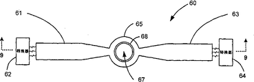
图25是本发明的顺序脉冲的行波加速器的示意图。Figure 25 is a schematic diagram of a sequential pulsed traveling wave accelerator of the present invention.
图26图解图25的顺序脉冲的行波加速器的短脉冲行波操作的示意图。26 illustrates a schematic diagram of short pulse traveling wave operation of the sequentially pulsed traveling wave accelerator of FIG. 25 .
图27是图解传统的电介质壁加速器的典型单元的长脉冲操作的示意图。FIG. 27 is a schematic diagram illustrating long pulse operation of a typical unit of a conventional dielectric wall accelerator.
具体实施方式Detailed ways
A.带有条形布鲁姆林的小型加速器A. Small Accelerator with Strip Bloomington
现在转到附图,图1-12显示用于本发明的小型的线性加速器,具有至少一个条形布鲁姆林模块,其引导第一和第二端之间的传播波阵面并且控制在第二端的输出脉冲。各布鲁姆林模块具有第一,第二,以及第三平面导体条,在第一和第二导体条之间有第一电介质条,而在第二和第三导体条之间有第二电介质条。另外,该小型线性加速器包括被连接以将第二导体条充电到高电势的高压电源,以及转换器,用于将第二导体条中的高电势转换至第一和第三导体条中的至少一个以在相应的电介质条中启动传播反极性波阵面。Turning now to the drawings, Figures 1-12 show a compact linear accelerator useful in the present invention, having at least one bar-shaped Bloomling module that directs a propagating wavefront between first and second ends and controls The output pulse of the second terminal. Each Bloomling module has first, second, and third planar conductor strips with a first dielectric strip between the first and second conductor strips and a second dielectric strip between the second and third conductor strips. Dielectric strip. Additionally, the compact linear accelerator includes a high voltage power supply connected to charge the second conductor strip to a high potential, and a converter for converting the high potential in the second conductor strip to at least one of the first and third conductor strips One to initiate a propagating anti-polarity wavefront in the corresponding dielectric strip.
小型线性加速器具有至少一个条形布鲁姆林模块,其引导第一和第二端之间的传播波阵面并且控制在第二端的输出脉冲。各布鲁姆林模块具有第一,第二,以及第三平面导体条,在第一和第二导体条之间有第一电介质条,而在第二和第三导体条之间有第二电介质条。另外,该小型线性加速器包括被连接以将第二导体条充电到高电势的高压电源,以及转换器,用于将第二导体条中的高电势转换至第一和第三导体条中的至少一个以在相应的电介质条中启动传播反极性波阵面。A compact linear accelerator has at least one bar-shaped Bloomling module that directs a propagating wavefront between first and second ends and controls output pulses at the second end. Each Bloomling module has first, second, and third planar conductor strips with a first dielectric strip between the first and second conductor strips and a second dielectric strip between the second and third conductor strips. Dielectric strip. Additionally, the compact linear accelerator includes a high voltage power supply connected to charge the second conductor strip to a high potential, and a converter for converting the high potential in the second conductor strip to at least one of the first and third conductor strips One to initiate a propagating anti-polarity wavefront in the corresponding dielectric strip.
图1-2显示总体地以参考标号10指示,并且包含连接到转换器18的单个布鲁姆林模块36的小型线性加速器的第一示范性实施例。该小型加速器还包括合适的高压电源(未显示),经过转换器18给布鲁姆林模块36提供高电压电势。一般地,布鲁姆林模块具有条构造,即长的窄的几何形状,典型地具有相同的宽度,然而并非必须如此。图1和2所示的特别的布鲁姆林模块11具有在第一端11和第二端12之间延伸,并与长度l相比,具有相对窄的宽度wn(图2,4)的细长的束或似板的线性构造。布鲁姆林模块的此条形构造操作以引导电信号波从第一端11传播到第二端12,从而在第二端控制输出脉冲。特别地,波阵面的形状可以通过合适地设置模块宽度来控制,例如通过如图6所示逐渐变细宽度。该条形构造使小型加速器能克服,如在背景技术中关于Carder的圆盘形模块讨论的,当被径向地指引以集中于中心孔时可能发生的传播波阵面的变化阻抗。并且用这样的方式,可以由模块10的似条或束的构造在没有使脉冲变形的情况下产生扁平的输出(电压)脉冲,并且从而防止粒子束接受随时间变化的能量增益。如在本文中以及在权利要求中使用的,第一端11其特征在于连接到转换器例如转换器18的端,以及第二端12是与负载区域,例如用于粒子加速的输出脉冲区域相邻的端。1-2 show a first exemplary embodiment of a small-scale linear accelerator generally indicated by the
如图1和2所示,基本的布鲁姆林模块10的窄类束的结构包括形状为窄条并且由同样显示为细长形不过更厚的条的介电材料分离的三个平面导体。特别地,第一平面导体条13和中间的第二平面导体条15由填充其间的空间的第一介电材料14分离。并且第二平面导体条15和第三平面导体条16由填充其间的空间的第二介电材料17分离。最好为,由介电材料产生的分离如同所示定位彼此平行的平面导体条13,15和16。第三介电材料19也被显示连接到平面导体条和电介质条13-17并盖在其顶上。第三介电材料19用来组合波并仅允许脉冲电压跨过真空壁,因而减少压力被施加于那个壁的时间并允许甚至更高的梯度。其还可以被用作在将其应用到加速器之前变换波,即提升电压,改变阻抗,等等的区域。同样地,第三介电材料19和第二端12,一般被显示为与由箭头20指示的负载区域相邻。特别地,箭头20代表粒子加速器的加速轴并且指在粒子加速的方向。希望的是通过两个电介质条,加速方向取决于快和慢传输线的路径,如在背景技术中讨论的。As shown in Figures 1 and 2, the narrow-bundle structure of the
在图1中,显示转换器18连接到在各第一端,即在模块36的第一端11连接到平面导体条13,15,和16。转换器用来初始连接外平面导体条13,16至地电势并且中间的导体条15至高压电源(未显示)。然后操作转换器18以在第一端施加短路以通过布鲁姆林模块启动传播电压波阵面并且在第二端产生输出脉冲。特别地,取决于布鲁姆林模块被设置用于对称的还是不对称的操作,转换器18可以在至少一个电介质中从第一端到第二端启动传播反极性波阵面。当设置用于不对称操作时,如图1和2所示,布鲁姆林模块以类似于Carder中说明的方式,包含对于介质层14,17不同的介电常数和厚度(d1≠d2)。布鲁姆林的不对称操作通过介质层产生不同的传播波速度。然而,当如图12所示布鲁姆林模块被设置用于对称的操作时,电介质条95,98具有相同介电常数,并且宽度和厚度(d1=d2)也相同。另外,如图12所示,磁性材料也被置于与第二电介质条98非常接近从而在那个条中波阵面的传播被阻碍。用这样的方式,转换器适合于仅在第一电介质条95中启动传播反极性波阵面。希望的是转换器18是对于不对称的或对称的布鲁姆林模块操作适合的转换器,例如,气体放电闸刀开关,表面击穿闸刀开关,固态转换器,光导转换器,等等。并且进一步地希望的是转换器和介电材料类型/尺寸的选择可以被合适地选择以使小型加速器能以各种加速梯度操作,包括例如超过每米二十兆伏的梯度。然而,作为设计的问题,较低的梯度也将是可实现的。In FIG. 1 , the
在一个最优实施例中,第二平面导体具有由贯穿第一电介质条的特性阻抗Z1=k1g1(w1,d1)限定的宽度w1。k1是由第一介电材料的磁导率对电容率的比的平方根限定的第一电介质条的第一电常数,g1是由邻近导体的几何形状效果限定的函数,而d1是第一电介质条的厚度。并且第二电介质条具有由贯穿第二电介质条的特性阻抗Z2=k2g2(w2,d2)限定的厚度。在这种情况下,k2是第二介电材料的第二电常数,g2是由邻近导体的几何形状效果限定的函数,而w2是第二平面导体条的宽度,而d2是第二电介质条的厚度。用这样的方式,因为在不对称的布鲁姆林模块中需要的不同电介质产生不同阻抗,通过调节关联线的宽度,阻抗现在可以保持不变量。因而将产生更大的能量传递至负载。In a preferred embodiment, the second planar conductor has a width w 1 defined by a characteristic impedance Z 1 =k 1 g 1 (w 1 ,d 1 ) through the first dielectric strip. k1 is the first permittivity of the first dielectric strip defined by the square root of the ratio of the permeability to permittivity of the first dielectric material, g1 is a function defined by the geometry effect of the adjacent conductor, and d1 is The thickness of the first dielectric strip. And the second dielectric strip has a thickness defined by a characteristic impedance Z 2 =k 2 g 2 (w 2 ,d 2 ) through the second dielectric strip. In this case, k2 is the second permittivity of the second dielectric material, g2 is a function defined by the geometrical shape effects of adjacent conductors, while w2 is the width of the second planar conductor strip, and d2 is The thickness of the second dielectric strip. In this way, since the different dielectrics required in the asymmetrical Bloomling modules produce different impedances, by adjusting the width of the associated lines, the impedance can now be kept constant. This will result in greater energy transfer to the load.
图4和5显示具有比第一和第二平面导体条41,42,以及第一和第二电介质条44,45的宽度更窄的宽度的第二平面导体条42的布鲁姆林模块的示范性实施例。在此特别的构造中,在背景技术中讨论的层对层耦合的破坏性干扰通过电极41和43的伸展被抑制,因为电极42不再能容易地耦合能量至先前的或随后的布鲁姆林。此外,模块的另一示范性实施例优选为具有沿纵向变化的宽度l,(参见图2,4)以控制并成型输出脉冲形状。此如图6所示,显示因为模块向内向中心负载区域径向地延伸而宽度逐渐变细。而在另一优选实施例中,布鲁姆林模块的介电材料和尺寸被如此选择以致,Z1大体上等于Z2。如先前讨论的,匹配阻抗防止将建立振荡输出的波的形成。Figures 4 and 5 show a Bloomling module with a second planar conductor strip 42 having a width narrower than the width of the first and second planar conductor strips 41, 42, and the first and second dielectric strips 44, 45. Exemplary embodiment. In this particular configuration, the destructive disturbance of the layer-to-layer coupling discussed in the background art is suppressed by the stretching of electrodes 41 and 43, since electrode 42 can no longer easily couple energy to the previous or subsequent Bloom Forest. Furthermore, another exemplary embodiment of the module preferably has a longitudinally varying width l, (see Figs. 2, 4) to control and shape the output pulse shape. This is shown in Figure 6, which shows a tapering in width as the modules extend radially inwardly towards the central load area. Yet in another preferred embodiment, the dielectric material and dimensions of the Bloomling modules are chosen such that Z1 is substantially equal to Z2 . As previously discussed, matching impedance prevents the formation of waves that would build up an oscillating output.
并且优选为,在不对称的布鲁姆林构造中,第二电介质条17具有大体上比第一电介质条14小的传播速度,例如3∶1,这里传播速度分别地由v2,和v1限定,这里v2=(μ2ε2)-0.5而v1=(μ1ε1)-0.5;磁导率μ1和电容率ε1是第一介电材料的材料常数;而磁导率μ2和电容率ε2是第二介电材料的材料常数。这可以通过为第二电介质条选择具有大于第一电介质条的介电常数即μ2ε2的介电常数,即μ1ε1的材料来实现。如图1所示,例如,第一电介质条的厚度表示为d1,而第二电介质条的厚度表示为d2,d2显示为大于d1。通过设置d2大于d1,不同的间隔和不同的介电常数的组合,在第二平面导体条15的两侧上,产生相同的特性阻抗Z。值得注意的是尽管在两半上特性阻抗可以是相同的,但是通过各半的信号的传播速度未必相同。虽然可以适当地选择电介质条的介电常数和厚度以引起不同的传播速度,希望的是细长形条状结构和构造不必利用不对称的布鲁姆林概念,即具有不同的介电常数和厚度的电介质。因为由细长形似束几何形状和布鲁姆林模块构造,而不是通过产生大加速度梯度的特别的方法,使得控制波形的优点成为可能,另一示范性实施例可以采用交替性的转换装置,例如对于涉及对称的布鲁姆林操作的图12讨论的。And preferably, in an asymmetric Brumlin configuration, the second
小型加速器可以替代地被设置为具有两个以上彼此对准堆叠的细长形布鲁姆林模块。例如,图3显示具有两个彼此对准堆叠在一起的布鲁姆林模块的小型加速器21。该两个布鲁姆林模块形成平面导体条和电介质条24-32的交替的堆,平面导体条32为两模块所共用。并且导体条在堆叠的模块的第一端22被连接至转换器33。电介质壁34被设置成盖在堆叠的模块的第二端23顶上,并且由加速轴箭头35指示相邻的负载区域。Small accelerators may alternatively be provided with two or more elongated Bloomling modules stacked in alignment with each other. For example, Figure 3 shows a
小型加速器也可以设置有至少两个安置为周边地围绕中心负载区域的布鲁姆林模块。此外,各周边地围绕的模块可以另外包括一个以上堆叠为对准第一模块的附加的布鲁姆林模块。例如,图6显示具有两个布鲁姆林模块堆51和53的小型加速器50的示范性实施例,该两个堆围绕中心负载区域56。各模块堆显示为一堆四个独立操作的布鲁姆林模块(图7),并且分离地连接到关联的转换器52,54。希望的是彼此对准的布鲁姆林模块堆增加沿加速轴部分的覆盖率。Small accelerators may also be provided with at least two Bloomling modules disposed peripherally around a central load area. Furthermore, each peripherally surrounding module may additionally include one or more additional Blooming modules stacked in alignment with the first module. For example, FIG. 6 shows an exemplary embodiment of a
在图8和9中小型加速器的另一示范性实施例以参考标号60显示,具有两个以上导体条,例如61,63,通过以65指示的环形电极连接在它们各自的第二端。环形电极构造运行以克服可能发生在例如图6和7,一个或多个周边地围绕的模块在没有完全地围绕其的情况下向中心负载区域延伸的排布中的任何的方位均分。如在图9中可以明显地看到,由61和62代表的各模块堆分别地连接至关联的转换器62和64。此外,图8和9显示沿环形电极的内径放置的绝缘体套筒68。替代地,也显示分离的绝缘体材料69放置在环状电极65之间。而作为在导体条之间使用的介电材料的选择,可以利用传导的66和绝缘的66’箔的交替层。选择层可以形成作为代替整体的电介质条的层状结构。Another exemplary embodiment of a compact accelerator is shown at
图10和11显示小型加速器的两个附加的示范性实施例,总体地在图10中以参考标号70指示,并且在图11中以参考标号80指示,各具有带有非线性的条状构造的布鲁姆林模块。在这种情况下,非线性的条状构造显示为曲线的或蛇形线形式。在图10中,加速器70包含四个模块71,73,75,和77,显示为周边地围绕并且向中心区域延伸。各模块71,73,75,和77,分别地连接至关联的转换器,72,74,76,和78。如可以从此排布看到的,各模块的第一和第二端之间的直接径向距离小于非线性模块的总长度,其允许加速器的小型同时增加电传输路径。图11显示与图10中的类似的排布,带有具有四个模块81,83,85,和87的加速器80,显示为周边地围绕并向中心区域延伸。各模块81,83,85,和87,分别地连接至关联的转换器,82,84,86,和88。此外,模块的径向地内端,即第二端,借助于环形电极89彼此连接,提供在图8中讨论的优点。Figures 10 and 11 show two additional exemplary embodiments of compact accelerators, indicated generally at
B.顺序脉冲的行波加速模式B. Traveling wave acceleration mode of sequential pulses
感应线性加速器(LIAs),在静态中沿其整个长度被短路。因而,带电粒子的加速依赖于该结构的能力以建立瞬态电场梯度并将施加的加速脉冲的连续的系列从邻接的脉冲形成线隔离。在先有技术LIAs中,此方法通过令脉冲形成线表现为一系列对于瞬态时间从该结构的内部堆叠的电压源,当更适宜时,存在带电粒子束。用于建立此加速度梯度并提供需要的绝缘的典型的方法是通过在加速器内部使用磁核芯以及使用脉冲形成线本身的通过时间(transmit time)。后者包括由任何连接电缆引起的增加的长度。在已经发生加速瞬态之后,因为磁核芯的饱和,系统再一次表现为沿其长度短路。这样的先有技术系统的缺点是由于加速区域的局限的间隔的程度,加速度梯度相当低(~0.2-0.5MV/m),并且磁性材料昂贵并且笨重。此外,即使最好的磁性材料也不能没有电能严重损耗的响应快速的脉冲,因而如果需要核芯,则制造此类型的高梯度加速器最好也只不过可能是不切实际的,而在最坏的情况下不是技术上可行的。Induction linear accelerators (LIAs) are short-circuited along their entire length in static state. Acceleration of charged particles thus relies on the ability of the structure to establish a transient electric field gradient and to isolate successive series of applied acceleration pulses from adjoining pulses forming a line. In prior art LIAs, this approach works by making the pulse-shaping line appear as a series of voltage sources stacked from within the structure for transient times, when preferably a charged particle beam is present. A typical method for establishing this acceleration gradient and providing the required insulation is by using a magnetic core inside the accelerator and using the transmit time of the pulse forming wire itself. The latter includes the added length caused by any connecting cables. After the acceleration transient has occurred, the system again appears to be shorted along its length because of the saturation of the magnetic core. Disadvantages of such prior art systems are that the acceleration gradient is rather low (-0.2-0.5 MV/m) due to the limited spacing of the acceleration regions, and the magnetic material is expensive and bulky. Furthermore, even the best magnetic materials cannot respond to fast pulses without severe losses in power, so if a core is required, it may only be impractical at best to make a high-gradient accelerator of this type, and at worst is not technically feasible.
图25显示本发明的顺序脉冲的行波加速器的示意图,总体地以参考标号160指示,具有长度l。加速器的传输线的每一个显示具有长度ΔR和宽度δl,而束射管具有直径d。配备触发控制器161,其顺序地触发一组转换器162以利用具有电长度(即脉冲宽度)τ的加速脉冲激励束射管的短轴长δl,以沿加速轴的长度产生单个虚拟行波164。特别地,顺序触发器/控制器能够顺序地触发转换器以致与带电粒子的轴向地横穿的脉冲束同步沿围绕加速轴的束射管产生行进的轴向电场以顺序地给予粒子能量。触发控制器161可以个别地触发转换器中的每一个。替代地,可以同时转换形成块的至少两个相邻的传输线并且顺序地转换相邻的块,以致通过各块形成加速脉冲。用这样的方式,两条以上转换/传输线的块激励束射管壁的短轴长nδl。δl是束射管壁对应于激励线的短轴长,并且n是在任何时刻相邻的激励线的数目,n≥1。FIG. 25 shows a schematic diagram of a sequentially pulsed traveling wave accelerator of the present invention, generally indicated by
用于说明目的的一些实例尺寸:d=8cm,τ=几个纳秒(例如对于质子加速1-5纳秒,对于电子加速100皮秒至几个纳秒),v=c/2,这里c=光速。然而,希望的是本发明可伸缩至实际上任何尺寸。优选地,束射管的直径d和长度l满足标准l>4d,以减少在电介质束射管的输入和输出端的散射场。此外,束射管优选满足标准:γτv>d/0.6,这里v是束射管壁上的波的速度,d是束射管的直径,τ是脉冲宽度,这里
不同于需要核芯以建立加速度梯度的此类型的大部分的加速器系统,本发明的加速器系统在没有核芯的情况下运行,因为如果满足标准nδl<l,则在一定时刻沿束射管的小剖面发生的束射管的电活化不短路。通过不使用核芯,本发明避免与核芯的使用相联系的各种问题,例如因为可达到的电压被ΔB限制而限制加速度,这里Vt=AΔB,这里A是核芯的横截面积。核芯的使用也促使限制加速器的重复率,因为需要脉冲电源使核芯复位。以给定的nδl脉冲的加速度由于邻近给定轴向部分的未被供给能量的传输线的瞬态绝缘性质而被从传导的外壳隔离。希望的是因为一些转换电流被分流到未被供给能量的传输线,而从未被供给能量的传输线的不完全的瞬态绝缘性质引起寄生波。这当然在没有磁芯绝缘的情况下发生以防止此旁路流泄。在一定条件下,可以有利地使用寄生波,例如在以下实例中说明的那样。在由仅转换快速的/高阻抗(低介电常数)线的不对称的条布鲁姆林s组成的开路布鲁姆林堆叠的构造中,在未被供给能量的传输线中产生的寄生波将在未被供给能量的线路上产生更高的电压,在慢线上提高电压时使电压提高超过初始带电状态较少的数量。这是因为当分压器受到相同注射电流之时两线串联出现。出现在加速器壁的波现在被提高至比初始带电的大的值,使得可达到更高的加速度梯度。Unlike most accelerator systems of this type which require a core to establish an acceleration gradient, the accelerator system of the present invention operates without a core because at a certain moment along the beam tube the The electrical activation of the beam tube that occurs in small sections does not short circuit. By not using a core, the invention avoids various problems associated with the use of a core, such as limiting acceleration because the achievable voltage is limited by ΔB, where Vt=AΔB, where A is the cross-sectional area of the core. The use of cores also contributes to limiting the accelerator's repetition rate because pulsed power is required to reset the core. Acceleration pulsed at a given nδl is isolated from the conductive enclosure due to the transient insulating properties of the unenergized transmission line adjacent to a given axial section. This is desirable because some of the switching current is shunted to the non-energized transmission line, and the incomplete transient insulating properties of the non-energized transmission line cause spurious waves. This of course happens without core insulation to prevent this bypass leakage. Under certain conditions, spurious waves can be advantageously used, such as illustrated in the following examples. In the configuration of an open-circuit Bloomling stack consisting of asymmetric strip Bloomlings switching only fast/high impedance (low dielectric constant) lines, spurious waves are generated in unenergized transmission lines A higher voltage will be produced on the unenergized line, increasing the voltage on the slow line by a lesser amount than the initial energized state. This is because the two wires appear in series when the voltage divider is subjected to the same injected current. The waves appearing at the accelerator wall are now boosted to a value greater than that of the initial charge, so that higher acceleration gradients can be achieved.
图26和27图解在长度L的束射管中产生的梯度的不同。图26显示具有小于长度L的宽度vτ的单脉冲行波。相反,图27显示所有的传输线被同时触发以产生跨过加速器的整个长度L的梯度的堆叠的布鲁姆林模块的典型操作。在这种情况下,vτ大于或等于长度L。Figures 26 and 27 illustrate the difference in gradients produced in beam tubes of length L. FIG. 26 shows a single pulse traveling wave with width vτ smaller than length L. FIG. In contrast, Figure 27 shows a typical operation of a stacked Brumlin module with all transmission lines triggered simultaneously to produce a gradient across the entire length L of the accelerator. In this case, vτ is greater than or equal to the length L.
C.带电粒子发生器:集成的脉冲离子源和注射器C. Charged particle generator: integrated pulsed ion source and injector
图13显示本发明的带电粒子发生器110的示范性实施例,具有集成到单个单元中的脉冲离子源112和注射器113。为了产生强脉冲离子束,需要提取束的调制和随后的聚束。首先,粒子发生器操作通过使用脉冲离子源112使用表面击穿放电以产生极稠密等离子体,建立强脉冲离子束。等离子体密度的估计量为超过7大气压,并且这样的放电是即时的以允许形成极短的脉冲。传统的离子源从体积内部的低压气体建立等离子体放电。从此体积,离子被提取并准直用于加速入加速器。这些系统通常限于提取的电流密度在0.25A/cm2以下。此低电流密度部分地是由于在提取界面的等离子体放电的强度。Figure 13 shows an exemplary embodiment of a charged
本发明的脉冲离子源具有至少两个利用绝缘体桥接的电极。关注的气体种类或者溶解在金属电极之内或者在二电极之间处于固体。此几何形状令在绝缘体上方产生的火花将那些物质接收入排出物并且为了提取入束而变为离子化。优选的,该至少两个电极利用绝缘,半绝缘,或半导体的材料桥接,通过其在这两个电极之间形成火花放电。包含处于原子或分子形式的希望的离子种类的材料在电极中或在电极附近。优选的,包含希望的离子种类的材料是氢的同位素,例如H2,或碳。此外,优选的,至少一个电极是半多孔的并且包含处于原子或分子形式的希望的离子种类的储层在那个电极下面。图14和15显示以参考标号112总体地指示的脉冲离子源的示范性实施例。显示陶瓷121在陶瓷的表面上具有阴极124和阳极123。阴极被显示为围绕盖在其下的H2储层114顶上的钯中心件124。希望的是阴极和阳极可以是反转的。并且孔板,即栅电极115被安置为带有与钯顶帽124对准的孔。The pulsed ion source of the present invention has at least two electrodes bridged by an insulator. The gas species of interest is either dissolved within the metal electrodes or is a solid between the two electrodes. This geometry causes the spark generated above the insulator to receive those species into the exhaust and become ionized for extraction into the beam. Preferably, the at least two electrodes are bridged by an insulating, semi-insulating, or semiconducting material, through which a spark discharge is formed between the two electrodes. A material containing the desired ionic species in atomic or molecular form is in or near the electrode. Preferably, the material containing the desired ionic species is an isotope of hydrogen, such as H2, or carbon. Furthermore, it is preferred that at least one electrode is semi-porous and that a reservoir comprising the desired ionic species in atomic or molecular form is beneath that electrode. 14 and 15 show an exemplary embodiment of a pulsed ion source, indicated generally at
如图15所示,在阴极和阳极电极之间施加高电压以产生电子发射。当这些电极初始处于接近真空条件之时,以足够的高电压,电子从阴极被场发射。这些电子横贯至阳极的空间并且当撞击阳极时产生局部加热。此加热释放出随后由电子撞击的分子,令它们变为离子化。这些分子可以或可以不必具有要求的种类。该离子化气体分子(离子)加速回到阴极并且,在这种情况下,撞击钯顶帽并且产生热。钯具有当被加热时,将允许气体,最显著的是氢,渗透入材料的性质。因而,当通过离子的加热足够使氢气局部地漏入该体积时,那些渗漏的分子被电子离子化并形成等离子体。并且当等离子体增加到足够的密度时,形成自保持的电弧。因而,放置在孔板的对面上的脉冲的带负电的电极可用于提取离子并且将它们注入加速器。在没有提取器电极的情况下,适当极性的电场可以被同样地用于提取离子。并且当电弧停止时,气体除去离子。如果电极由吸气材料构成,则气体被吸收入金属电极,将要随后用于下次循环。不被再吸收的气体被真空系统抽出。这类源的优点是在脉冲的应用中将真空系统上的气体负载减到最小。As shown in Figure 15, a high voltage is applied between the cathode and anode electrodes to generate electron emission. When these electrodes are initially in near-vacuum conditions, at a sufficiently high voltage, electrons are field-emitted from the cathode. These electrons traverse the space to the anode and generate localized heating when hitting the anode. This heating releases molecules that are then struck by electrons, causing them to become ionized. These molecules may or may not be of the required species. The ionized gas molecules (ions) are accelerated back to the cathode and, in this case, hit the palladium top cap and generate heat. Palladium has the property of allowing gases, most notably hydrogen, to permeate the material when heated. Thus, when the heating by the ions is sufficient to locally leak hydrogen gas into the volume, those leaking molecules are ionized by electrons and form a plasma. And when the plasma increases to a sufficient density, a self-sustaining arc is formed. Thus, pulsed negatively charged electrodes placed on opposite sides of the aperture plate can be used to extract ions and inject them into the accelerator. In the absence of extractor electrodes, an electric field of appropriate polarity can likewise be used to extract ions. And when the arc stops, the gas removes the ions. If the electrodes consist of a getter material, the gas is absorbed into the metal electrode to be subsequently used for the next cycle. The gas that is not reabsorbed is drawn out by the vacuum system. The advantage of this type of source is to minimize the gas load on the vacuum system in pulsed applications.
由图13所示的集成的注入器部113提供从脉冲离子源112到线性加速器的输入的带电粒子提取,聚焦和传输。特别地,带电粒子发生器的注入器部113也用来将带电离子束聚焦到靶上,其可以是带电粒子治疗设备中的病人或者用于同位素生成的靶或者用于荷电粒子束的任何其它合适的靶。此外,本发明的集成注射器允许带电粒子发生器仅使用用于传输束和聚焦在病人上的电聚焦场。在系统中没有磁铁。该系统可以独立地传递大范围束电流,能量和斑点尺寸。Charged particle extraction, focusing and transport from the input of the
图13显示注射器113关于脉冲离子源112的示意配置,而图21显示和线性加速器131集成的组合的带电粒子发生器132的示意配置。整个小型的高梯度的加速器的束提取,传输和聚焦由包含位于带电粒子源和高梯度的加速器之间的栅电极115,提取电极116,聚焦电极117,以及栅极119的注射器控制。然而,值得注意的是最小的传输系统应该由提取电极,聚焦电极和栅极组成。并且如果需要它们,则对于各功能可以使用一个以上的电极。所有的电极还可以成型为使系统性能最佳化,如图18所示。带有快速的调制电压的栅电极115用来在几纳秒之内打开和关闭带电粒子束。在为质子治疗而设计的高梯度的加速器中作为栅压的函数的模拟的提取束电流在图17中给出,而对于各种栅压的最终束斑在图16中给出。在由发明人进行的模拟中,标称的栅电极电压是9kV,提取电极是在980kV,聚焦电极是在90kV,栅电极是在980kV,而高梯度加速器的加速度梯度是100MV/m。因为图16显示最终斑点大小不对栅电极的电压设置灵敏,所以栅压提供容易的旋钮以开启/关闭束电流,如图17指示的那样。FIG. 13 shows a schematic configuration of
高梯度的加速器系统的注射器使用栅电极和提取电极以提取和捕捉空间电荷支配束,其电流由提取电极上的电压确定。加速器系统使用一组至少一个聚焦电极117以聚焦束到靶上。图18所示的电势等值线绘图,图解提取电极和聚焦电极是怎样运行的。最小的聚焦/运输系统,即,一个提取电极和一个聚焦电极,用于这个情况。在高梯度的加速器入口,提取电极,聚焦电极和栅电极上的电压是980kV,90kV和980kV。图18显示成型的提取电极电压在栅电极和提取电极之间设置间隙电压。图18也显示成型的提取电极,成型的聚焦电极和栅电极上的电压产生静电聚焦-散焦-聚焦区域,即,单透镜,其对带电粒子束提供强大的网聚焦力。Injectors for high-gradient accelerator systems use grid electrodes and extraction electrodes to extract and trap space-charge-dominated beams, the current of which is determined by the voltage on the extraction electrodes. The accelerator system uses a set of at least one focusing
尽管使用单透镜聚焦束不是新的,本发明的加速器系统完全地不含聚焦磁铁。此外,本发明也将单透镜与其它电极组合以允许束斑尺寸在靶可调并独立于束电流和能量。在注射器的出口或我们的高梯度的加速器的入口,有栅电极119。提取电极和栅电极将设置为相同电压。通过让栅电极的电压与提取电极的电压相同,注入加速器的束的能量将保持相同,而与成型的聚焦电极上的电压设置无关。因此,改变成型的聚焦电极上的电压将仅改变单透镜的强度而不是束能量。因为通过提取电极的电压确定束电流,可以通过调节成型的聚焦电极的电压自由地调谐最终斑点,不依赖束电流和能量。在这样的系统中,同样希望的是附加的聚焦由轴向电场中的适当的梯度(即dEz/dz)引起,并且另外作为电场的时间变率的结果(即在z=z0的dE/dt)。Although the use of a single lens to focus the beam is not new, the accelerator system of the present invention is entirely free of focusing magnets. Furthermore, the present invention also combines a single lens with other electrodes to allow the beam spot size to be tunable at the target and independent of beam current and energy. At the exit of the injector or the entrance of our high gradient accelerators, there is a
图19给出对于通过具有各种聚焦电极电压设置的无磁铁的250MeV质子高梯度的加速器的束传输的模拟的射束包络。利用在左给出的它们的相应的聚焦电极电压,这些绘图清楚地显示靶上的250MeV的质子束的斑点大小可以通过调节聚焦电极电压容易地调谐。并且对于各种质子束能量的斑点尺寸对聚焦电极电压的绘图如图20所示。对于各质子能量标绘两个曲线。上曲线给出束的边缘半径,而下曲线给出核心半径。这些曲线图显示,对于70-250MeV,100mA的质子束,通过调节具有100MV的加速梯度的高梯度的质子治疗加速器上的聚焦电极电压,可以获得大范围斑点尺寸(2mm-2cm直径)。Figure 19 presents simulated beam envelopes for beam delivery through a magnetless 250 MeV proton high gradient accelerator with various focusing electrode voltage settings. With their corresponding focusing electrode voltages given on the left, these plots clearly show that the spot size of the 250 MeV proton beam on the target can be easily tuned by adjusting the focusing electrode voltage. And a plot of spot size versus focusing electrode voltage for various proton beam energies is shown in FIG. 20 . Two curves are plotted for each proton energy. The upper curve gives the edge radius of the bundle, while the lower curve gives the core radius. These graphs show that, for a 70-250 MeV, 100 mA proton beam, a wide range of spot sizes (2 mm-2 cm diameter) can be obtained by adjusting the focusing electrode voltage on a high gradient proton therapy accelerator with an acceleration gradient of 100 MV.
采用这样的集成的带电粒子发生器的小型的高梯度的加速器系统可以独立地传递大范围束电流,能量和斑点尺寸。整个加速器的束提取,传输和聚焦由位于带电粒子源和高梯度的加速器之间的栅电极,成型的提取电极,成型的聚焦电极和栅电极控制。提取电极和栅电极具有相同电压设置。它们之间的成型的聚焦电极设置在较低的电压,其形成单透镜并提供用于斑点大小的调谐钮。虽然最小的传输系统由提取电极,聚焦电极和栅电极组成,但是如果系统确实需要强聚焦力,则可以在成型的聚焦电极和栅电极之间添加更多的具有交变电压的单透镜。Small, high-gradient accelerator systems employing such an integrated charged particle generator can independently deliver a wide range of beam currents, energies, and spot sizes. Beam extraction, delivery and focusing of the entire accelerator is controlled by a grid electrode, a shaped extraction electrode, a shaped focusing electrode and a grid electrode located between the charged particle source and the high gradient accelerator. The extraction electrode and the gate electrode have the same voltage setting. A shaped focusing electrode between them is set at a lower voltage, which forms a single lens and provides a tuning knob for spot size. Although the smallest transmission system consists of extraction electrode, focusing electrode and grid electrode, if the system really needs strong focusing force, more single lenses with alternating voltage can be added between the shaped focusing electrode and grid electrode.
D.用于医学治疗的可激励的小型加速器系统D. Excitable Small Accelerator Systems for Medical Therapy
图21显示本发明的示范性的可激励的小型加速器系统130的示意图,其具有集成地安装或否则位于小型线性加速器131的输入端的带电粒子发生器132以形成带电粒子束并沿加速轴将束注入小型加速器。通过用这样的方式将带电粒子发生器集成至加速器,可以实现能够由如箭头135指示的致动机构134,以及束136-138单元式激励的具有单元结构的相对紧凑的尺寸。在先前的系统中,因为它们的规模尺寸的关系,需要磁铁从边远区传输束。相反,因为在本发明中显著地减少规模尺寸,所以都可以在极接近于要求的目标位置之处,并且在没有利用磁铁的情况下生成,控制,以及传输例如质子束的束。这样紧凑的系统对于例如,在医学治疗加速器应用中的使用将是理想的。21 shows a schematic diagram of an exemplary excitable
这样的单元式设备可以安装在总体地以133显示的支撑结构上,其被构型为启动集成的粒子发生器-线性加速器以直接地控制带电粒子束的位置以及从而产生的束斑。用于安装小型加速器和带电粒子源的单元式组合的各种构造如图22-24所示,但是不局限于此。特别地,图22-24显示本发明的示范性实施例,其显示安装在各种类型的支撑结构上,以致可激励用于控制束指向的组合的小型加速器/带电粒子源。加速器和带电粒子源可以悬吊以及与固定的架台铰接并且指向病人(图22和23)。在图22中,通过绕以143指示的重心旋转单元设备可允许单元式激励。如图22所示,集成的小型的发生器-加速器可以优选地绕其重心枢轴地驱动以减少指向加速束需要的能量。然而,希望的是在本发明范围内可允许其它安装结构和支撑结构用于驱动这样的小型加速器和带电粒子源的紧凑和整体组合。Such a unitary device may be mounted on a support structure shown generally at 133 configured to activate the integrated particle generator-linac to directly control the position of the charged particle beam and thus the resulting beam spot. Various configurations for the modular combination of a compact accelerator and a charged particle source are shown in Figures 22-24, but are not limited thereto. In particular, Figures 22-24 show exemplary embodiments of the invention showing a combined small accelerator/charged particle source mounted on various types of support structures so that it can be excited for controlling beam pointing. The accelerator and charged particle source can be suspended and articulated to a fixed gantry and directed toward the patient (Figs. 22 and 23). In FIG. 22 , unitary excitation is allowed by rotating the unit device about the center of gravity indicated at 143 . As shown in Figure 22, the integrated small generator-accelerator can preferably be pivotally driven about its center of gravity to reduce the energy required to direct the accelerating beam. However, it is contemplated that other mounting structures and support structures may be permitted within the scope of the present invention for driving such a compact and integral combination of a small accelerator and charged particle source.
希望的是各种加速器构造可以用于与带电粒子发生器集成,其能够小型可激励的结构。例如,加速器构造可以采用在先前说明的布鲁姆林模块结构中的两个传输线。优选地,传输线是平行板传输线。此外,传输线优选地具有如图1-12所示的条状构造。此外,可以使用具有快速的(纳秒)闭合时间的各种类型的高电压转换器,例如,SiC光导转换器,气体转换器,或油开关。It is hoped that various accelerator configurations can be used for integration with charged particle generators, which enable small energizable structures. For example, the accelerator configuration can employ the two transmission lines in the previously described Brumlin module configuration. Preferably, the transmission line is a parallel plate transmission line. Furthermore, the transmission line preferably has a strip configuration as shown in Figures 1-12. Furthermore, various types of high voltage converters with fast (nanosecond) closing times can be used, eg SiC photoconductive converters, gas converters, or oil switches.
并且在该领域中已知的各种致动机构和系统控制方法可以用于控制加速器系统的激励与操作。例如,简单球旋,步进马达,螺线管,电激活的转发器和/或气胎,等等,可能用来控制加速器束定位和活动。这允许射束径迹的编程即使不和普遍地用于CNC设备的程序设计语言一致,也与其非常类似。希望的是致动机构运行以使集成的粒子发生器一加速器进入机械的动作或活动以致控制加速的射束方向和束斑位置。在这点上,该系统具有至少一个旋转自由度(例如用于围绕质心旋转),但是最好为具有6个自由度(DOF),其是完全地指定身体或系统的迁移或变形的位置的独立的位移的设置,包括三个平动和三个转动,如在该领域中已知的。平动代表具有在三维中的每一个中移动的能力,而转动代表具有改变绕三个垂直轴的角的能力。And various actuation mechanisms and system control methods known in the art can be used to control the excitation and operation of the accelerator system. For example, simple ball spinners, stepper motors, solenoids, electrically activated transponders and/or pneumatic tires, etc., may be used to control accelerator beam positioning and movement. This allows the programming of beam paths to closely resemble, if not correspond to, programming languages commonly used for CNC equipment. It is desirable for the actuating mechanism to operate to bring the integrated particle generator-accelerator into mechanical action or activity so as to control the accelerated beam direction and beam spot position. In this regard, the system has at least one rotational degree of freedom (e.g. for rotation about the center of mass), but preferably has 6 degrees of freedom (DOF), which fully specify the location of migration or deformation of the body or system The set of independent displacements, including three translations and three rotations, is known in the art. Translation represents the ability to move in each of three dimensions, while rotation represents the ability to change angles about three perpendicular axes.
加速的射束参数的精度可以通过设计入加速器的控制和瞄准系统的主动的定位,监控,和反馈定位系统(例如位于病人145的监视器)控制,如由图22中的测量盒147代表的。并且系统控制器146被显示为控制加速器系统,其可以基于以下参数的至少一个:射束方向,束斑位置,束斑尺寸,剂量,束强度,和束能量。由基于布拉格峰的能量相对精密地控制深度。系统控制器优选地还包括用于监控和提供关于至少一个参数的前馈数据的前馈系统。并且由带电粒子和加速器产生的束可以被设置为对病人产生振动的投影。优选地,在一个实施例中,振动的投影是具有连续地变化的半径的圆。在任何情况下,可以基于以下的一个或组合主动地控制束的应用:位置,剂量,斑点尺寸,束强度,束能量。The accuracy of the accelerated beam parameters can be controlled by an active positioning, monitoring, and feedback positioning system (such as a monitor located on the patient 145) designed into the accelerator's control and aiming system, as represented by
虽然已经说明和/或图解特定的操作程序,材料,温度,参数,以及特定的实施例,但这并不是用作限制的。改进和变化可以对本领域技术人员显而易见,并且意图仅仅由附加的权利要求的范围限制本发明。Although specific operating procedures, materials, temperatures, parameters, and specific examples have been described and/or illustrated, these are not intended to be limiting. Modifications and changes may be apparent to those skilled in the art, and it is intended that the invention be limited only by the scope of the appended claims.
Claims (15)


Applications Claiming Priority (9)
| Application Number | Priority Date | Filing Date | Title |
|---|---|---|---|
| US73012805P | 2005-10-24 | 2005-10-24 | |
| US73016105P | 2005-10-24 | 2005-10-24 | |
| US73012905P | 2005-10-24 | 2005-10-24 | |
| US60/730,129 | 2005-10-24 | ||
| US60/730,128 | 2005-10-24 | ||
| US60/730,161 | 2005-10-24 | ||
| US79801606P | 2006-05-04 | 2006-05-04 | |
| US60/798,016 | 2006-05-04 | ||
| PCT/US2006/041548 WO2008033149A2 (en) | 2005-10-24 | 2006-10-24 | Sequentially pulsed traveling wave accelerator |
Publications (2)
| Publication Number | Publication Date |
|---|---|
| CN101406110A CN101406110A (en) | 2009-04-08 |
| CN101406110B true CN101406110B (en) | 2011-04-06 |
Family
ID=38983790
Family Applications (1)
| Application Number | Title | Priority Date | Filing Date |
|---|---|---|---|
| CN2006800490112A Expired - Fee Related CN101406110B (en) | 2005-10-24 | 2006-10-24 | Sequentially pulsed traveling wave accelerator |
Country Status (7)
| Country | Link |
|---|---|
| EP (1) | EP1946624B1 (en) |
| JP (1) | JP5496511B2 (en) |
| KR (1) | KR20080059395A (en) |
| CN (1) | CN101406110B (en) |
| AU (1) | AU2006348161A1 (en) |
| CA (1) | CA2627311A1 (en) |
| WO (1) | WO2008033149A2 (en) |
Families Citing this family (14)
| Publication number | Priority date | Publication date | Assignee | Title |
|---|---|---|---|---|
| US7710051B2 (en) * | 2004-01-15 | 2010-05-04 | Lawrence Livermore National Security, Llc | Compact accelerator for medical therapy |
| US20090224700A1 (en) * | 2004-01-15 | 2009-09-10 | Yu-Jiuan Chen | Beam Transport System and Method for Linear Accelerators |
| DE102008031634A1 (en) * | 2008-07-04 | 2010-01-14 | Siemens Aktiengesellschaft | Accelerator for accelerating charged particles and method for operating an accelerator |
| CN102014569A (en) * | 2009-09-24 | 2011-04-13 | 四川省科学城久远磁性材料有限责任公司 | Dielectric-wall accelerator acceleration unit |
| CN102202456B (en) * | 2010-03-26 | 2012-12-26 | 四川省科学城久远磁性材料有限责任公司 | Accelerating pulse forming device of dielectric wall accelerator |
| CN102202457A (en) * | 2010-03-26 | 2011-09-28 | 四川省科学城久远磁性材料有限责任公司 | Dielectric wall accelerator |
| KR101103666B1 (en) * | 2010-04-29 | 2012-01-11 | 한국전기연구원 | Compact bloomline high voltage pulse generator using solid insulator |
| KR101243185B1 (en) * | 2011-03-30 | 2013-03-14 | 한국전기연구원 | Blumlein Line high voltage pulse generator with variable pulse width |
| KR101298971B1 (en) * | 2011-12-16 | 2013-08-23 | 한국전기연구원 | Impedance matching peaking switch for very fast rising high voltage pulse |
| US8598813B2 (en) * | 2012-01-17 | 2013-12-03 | Compact Particle Acceleration Corporation | High voltage RF opto-electric multiplier for charge particle accelerations |
| WO2013114351A2 (en) * | 2012-01-31 | 2013-08-08 | HIL Applied Medical Ltd. | Laser activated magnetic field manipulation of laser driven ion beams |
| RU2534227C2 (en) * | 2012-12-18 | 2014-11-27 | Федеральное государственное бюджетное образовательное учреждение высшего профессионального образования "Самарский государственный аэрокосмический университет имени академика С.П. Королева (национальный исследовательский университет)" (СГАУ) | High-speed solid particle accelerator |
| RU189818U1 (en) * | 2019-01-29 | 2019-06-05 | федеральное государственное автономное образовательное учреждение высшего образования "Самарский национальный исследовательский университет имени академика С.П. Королева" | High Speed Solid Microparticle Accelerator |
| JP7771018B2 (en) * | 2022-08-24 | 2025-11-17 | 株式会社東芝 | Accelerated particle generating device and accelerated particle generating method |
Citations (3)
| Publication number | Priority date | Publication date | Assignee | Title |
|---|---|---|---|---|
| US5811944A (en) * | 1996-06-25 | 1998-09-22 | The United States Of America As Represented By The Department Of Energy | Enhanced dielectric-wall linear accelerator |
| US5821705A (en) * | 1996-06-25 | 1998-10-13 | The United States Of America As Represented By The United States Department Of Energy | Dielectric-wall linear accelerator with a high voltage fast rise time switch that includes a pair of electrodes between which are laminated alternating layers of isolated conductors and insulators |
| CN1455635A (en) * | 2003-06-06 | 2003-11-12 | 南京大学 | Energy-adjustable electronic linear accelerator |
Family Cites Families (3)
| Publication number | Priority date | Publication date | Assignee | Title |
|---|---|---|---|---|
| US5140158A (en) * | 1990-10-05 | 1992-08-18 | The United States Of America As Represented By The United States Department Of Energy | Method for discriminative particle selection |
| US6331194B1 (en) * | 1996-06-25 | 2001-12-18 | The United States Of America As Represented By The United States Department Of Energy | Process for manufacturing hollow fused-silica insulator cylinder |
| US7173385B2 (en) * | 2004-01-15 | 2007-02-06 | The Regents Of The University Of California | Compact accelerator |
-
2006
- 2006-10-24 KR KR1020087009514A patent/KR20080059395A/en not_active Withdrawn
- 2006-10-24 CN CN2006800490112A patent/CN101406110B/en not_active Expired - Fee Related
- 2006-10-24 WO PCT/US2006/041548 patent/WO2008033149A2/en not_active Ceased
- 2006-10-24 CA CA002627311A patent/CA2627311A1/en not_active Abandoned
- 2006-10-24 EP EP06850535.3A patent/EP1946624B1/en not_active Not-in-force
- 2006-10-24 AU AU2006348161A patent/AU2006348161A1/en not_active Abandoned
- 2006-10-24 JP JP2008536618A patent/JP5496511B2/en not_active Expired - Fee Related
Patent Citations (3)
| Publication number | Priority date | Publication date | Assignee | Title |
|---|---|---|---|---|
| US5811944A (en) * | 1996-06-25 | 1998-09-22 | The United States Of America As Represented By The Department Of Energy | Enhanced dielectric-wall linear accelerator |
| US5821705A (en) * | 1996-06-25 | 1998-10-13 | The United States Of America As Represented By The United States Department Of Energy | Dielectric-wall linear accelerator with a high voltage fast rise time switch that includes a pair of electrodes between which are laminated alternating layers of isolated conductors and insulators |
| CN1455635A (en) * | 2003-06-06 | 2003-11-12 | 南京大学 | Energy-adjustable electronic linear accelerator |
Also Published As
| Publication number | Publication date |
|---|---|
| CA2627311A1 (en) | 2008-03-20 |
| JP2009512985A (en) | 2009-03-26 |
| WO2008033149A3 (en) | 2008-05-08 |
| EP1946624B1 (en) | 2015-09-16 |
| KR20080059395A (en) | 2008-06-27 |
| CN101406110A (en) | 2009-04-08 |
| WO2008033149A2 (en) | 2008-03-20 |
| AU2006348161A1 (en) | 2008-03-20 |
| EP1946624A2 (en) | 2008-07-23 |
| JP5496511B2 (en) | 2014-05-21 |
Similar Documents
| Publication | Publication Date | Title |
|---|---|---|
| US7576499B2 (en) | Sequentially pulsed traveling wave accelerator | |
| US7710051B2 (en) | Compact accelerator for medical therapy | |
| EP2158796B1 (en) | Beam transport system and method for linear accelerators | |
| US10181376B2 (en) | Electron-coupled transformer | |
| CN101406110B (en) | Sequentially pulsed traveling wave accelerator | |
| US20100059665A1 (en) | Contraband detection system | |
| US4553256A (en) | Apparatus and method for plasma generation of x-ray bursts | |
| US20100133445A1 (en) | Ion beam control apparatus and method | |
| Vintizenko | Linear induction accelerators for high-power microwave devices | |
| Masugata et al. | Development of bipolar-pulse accelerator for intense pulsed ion beam acceleration | |
| Miley et al. | RF ion source-driven IEC design and operation | |
| Wang | A Tesla-Blumlein PFL-bipolar pulsed power generator | |
| AU2013201537B2 (en) | Electron-coupled transformer | |
| Struve et al. | Status of the 2 MA driver for creating 2 MG magnetic fields for cluster fusion experiments | |
| Caporaso et al. | Compact accelerator | |
| Humphries Jr et al. | Scanning beam switch experiment for intense rf power generation | |
| Loisch et al. | The spherical theta pinch and its applications | |
| Poukey et al. | PIJLSELAC PROGRAM |
Legal Events
| Date | Code | Title | Description |
|---|---|---|---|
| C06 | Publication | ||
| PB01 | Publication | ||
| C10 | Entry into substantive examination | ||
| SE01 | Entry into force of request for substantive examination | ||
| C14 | Grant of patent or utility model | ||
| GR01 | Patent grant | ||
| CF01 | Termination of patent right due to non-payment of annual fee | ||
| CF01 | Termination of patent right due to non-payment of annual fee |
Granted publication date: 20110406 Termination date: 20201024 |