CN101405753A - Card capable of performing true/false judgment by a fluorescent particle chip - Google Patents
Card capable of performing true/false judgment by a fluorescent particle chip Download PDFInfo
- Publication number
- CN101405753A CN101405753A CNA2006800476488A CN200680047648A CN101405753A CN 101405753 A CN101405753 A CN 101405753A CN A2006800476488 A CNA2006800476488 A CN A2006800476488A CN 200680047648 A CN200680047648 A CN 200680047648A CN 101405753 A CN101405753 A CN 101405753A
- Authority
- CN
- China
- Prior art keywords
- card
- chip
- hologram
- light
- information
- Prior art date
- Legal status (The legal status is an assumption and is not a legal conclusion. Google has not performed a legal analysis and makes no representation as to the accuracy of the status listed.)
- Granted
Links
Images


Landscapes
- Credit Cards Or The Like (AREA)
- Holo Graphy (AREA)
Abstract
Description
技术领域 technical field
本发明涉及卡、纸币、证券等容易被伪造而需要真伪认证的物品的结构以及对该物品的真伪进行认证的方法。The present invention relates to the structure of items such as cards, banknotes, and securities that are easily counterfeited and require authenticity authentication, and a method for authenticating the items.
背景技术 Background technique
在被称为卡社会的今天,出现数量众多的卡,银行的现金卡、信托公司的信用卡等与所有者财产相关的卡、作为有价证券的预付卡以及驾驶执照、健康保险证、护照等与身份证明有关的卡被使用。In today's so-called card society, there are a large number of cards, such as cash cards of banks, credit cards of trust companies and other cards related to the owner's property, prepaid cards as securities, driver's licenses, health insurance cards, passports, etc. Cards associated with identification are used.
与财产相关的卡以及作为有价证券的卡大多在设置于表面或者背面的磁条中写入所需信息,使用ATM(Automatic Teller′s Machine:自动提款机)等自动设备或手动读取装置从磁条中读取磁信息并执行各种处理。Cards related to property and cards used as securities are mostly written with the required information on the magnetic stripe installed on the front or back, and are read by automatic equipment such as ATM (Automatic Teller's Machine: automatic teller machine) or manually The device reads magnetic information from the magnetic strip and performs various processing.
图1所示的是目前的现金卡处理流程的例子。Figure 1 shows an example of the current cash card processing flow.
(1)当卡所有人将现金卡插入到ATM等终端装置的卡插入口中时,卡插入口的传感器对其进行检测,并将卡取入到装置中。(1) When the card owner inserts the cash card into the card slot of a terminal device such as an ATM, the sensor of the card slot detects it and takes the card into the device.
(2)在取入卡时,终端装置从卡的磁记录部中读取卡信息。在现金卡的情况下,读入银行码、分行码、账户类别、账户号等卡信息。并且,在信用卡的情况下,卡识别号、有效期限、账户类别、账户号作为卡信息被记录在磁记录部中。此外,存在在现金卡或者信用卡中记录有密码的情况,在此情况下,密码也被读出。(2) When the card is taken in, the terminal device reads the card information from the magnetic recording portion of the card. In the case of a cash card, card information such as a bank code, a branch code, an account type, and an account number is read. In addition, in the case of a credit card, a card identification number, an expiration date, an account type, and an account number are recorded in the magnetic recording unit as card information. In addition, there are cases where a password is recorded on a cash card or a credit card, and in this case, the password is also read out.
(3)终端装置判断所插入的卡是否是能够在该终端装置中处理的卡。(3) The terminal device judges whether or not the inserted card is a card that can be handled by the terminal device.
(4)在根据所读入的卡信息未被确认是表示能够处理的信息的情况下,或者,即便是正规的卡而由于破损或者污浊等而不能够读取卡信息的情况下,终端装置将该卡作为不能处理的不合适的卡而吐出。(4) When the read card information is not confirmed to be information indicating that it can be processed, or when the card information cannot be read due to damage or contamination even if it is a legitimate card, the terminal device Discard the card as an unsuitable card that cannot be dealt with.
(5)在卡是正规卡并且磁记录部的信息被正确地读取的情况下,开始与主机进行通信。(5) When the card is a legitimate card and the information of the magnetic recording unit has been read correctly, communication with the host computer is started.
(6)主机请求输入密码。(6) The host requests to enter a password.
(7)对应于来自主机的请求,卡利用者输入密码。(7) The card user inputs the password in response to the request from the host computer.
(8)当卡利用者对应于来自主机的请求而输入密码时,主机将所输入的密码与在主机中存储的对应于所读取的卡信息的密码进行比较。(8) When the card user inputs a password in response to a request from the host, the host compares the input password with a password stored in the host corresponding to the read card information.
(9)在不一致的情况下,在卡的磁记录部中对此进行记录并请求再次输入密码,当再次输入的密码正确时,并进行之后的手续,在不一致的情况下,同样地,请求再一次输入密码,当密码输入错误累计成为三次时,使卡无效并且执行取入到终端装置内等的无效处分。(9) In the case of inconsistency, record this in the magnetic recording part of the card and request to re-enter the password. When the re-entered password is correct, perform subsequent procedures. The password is input again, and when the wrong password is entered three times in total, the card is invalidated and invalidation measures such as taking it into the terminal device are executed.
(10)在一致的情况下,主机判断卡利用者是正确的卡所有人,请求输入提款金额。(10) When they match, the host judges that the card user is the correct card owner, and requests input of the withdrawal amount.
(11)利用者输入要求提款的金额。(11) The user inputs the amount requested for withdrawal.
(12)如果要求提款的金额适当,则送出该金额的现金,将现金卡从终端装置中退出,并执行针对存折的记账或者发行处理明细书,交易结束。并且,在密码被记录在现金卡中的情况下,该密码作为正确的密码进行交易,但是,之后从磁记录部中擦除该密码。(12) If the amount requested for withdrawal is appropriate, the cash of the amount is sent out, the cash card is withdrawn from the terminal device, and the bookkeeping for the passbook or the issuance of a processing statement is performed, and the transaction is completed. And, when the password is recorded in the cash card, the password is used as the correct password for transactions, but the password is erased from the magnetic recording unit afterwards.
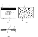
图2(a)所示的是图1示出的当前现金卡处理流程中所使用的现金卡的例子。在该图中,1是由塑胶等构成的现金卡主体,在其表面侧形成有记录了信息的磁条2及表示现金卡插入方向的箭头3。并且,省略了图示,但是,所需事项被登载为压花文字。Figure 2(a) shows an example of cash cards used in the current cash card processing flow shown in Figure 1 . In this figure, 1 is a cash card main body made of plastic or the like, and a
使用被称为刷读器(skimmer)的装置能够容易地读取写入到磁条中的信息,所以,产生制作伪造卡并屡次使用伪造卡的损失。The information written in the magnetic stripe can be easily read using a device called a skimmer, so there is a loss of making a counterfeit card and using the counterfeit card repeatedly.
作为其对策,使用内置有半导体存储器的IC卡来代替磁卡,银行等正在计划普及。As a countermeasure against this, IC cards incorporating semiconductor memory are used instead of magnetic cards, and banks and the like are planning to popularize them.
但是,即使是这种IC卡,也能够读取在存储器中保存的信息,在花费工夫进行伪造的情况下,也不能说是绝对安全的。此外,IC卡与磁卡相比是非常贵的,不能期待迅速普及。However, even with such an IC card, the information stored in the memory can be read, and it cannot be said to be absolutely safe even if it takes a lot of effort to forge it. In addition, IC cards are very expensive compared with magnetic cards, and rapid popularization cannot be expected.
在银行现金卡的情况下,只在一个国家可以使用就行了,但是,在信用卡的情况下,需要也能够在外国使用,将在全世界使用的全部磁卡即信用卡置换为规格统一的IC卡,这在事实上也是不可能的。In the case of a bank cash card, it is sufficient that it can be used in only one country. However, in the case of a credit card, it is necessary to be able to use it in a foreign country. All the magnetic cards used in the world, that is, credit cards, will be replaced with IC cards with uniform specifications. This is also impossible in fact.
并且,在现金卡和信用卡上进行压花加工并设置所有者名字等信息,这些信息在磁信息中也被使用,所以,压花信息成为伪造卡制作的线索。In addition, cash cards and credit cards are embossed and information such as the owner's name is set, and this information is also used in magnetic information, so the embossed information becomes a clue for counterfeiting the card.
在遭遇这些磁卡或者IC卡丢失或者被盗的情况下,所有者容易注意到该事实,但是,在被盗后返回到手里的情况下,特别是在没有注意到而返回的情况下,容易发生使用伪造卡造成的损失。In the case where these magnetic cards or IC cards are lost or stolen, the owner is likely to notice the fact, but, in the case of returning it to the hand after being stolen, especially in the case of returning without noticing, it is easy to happen. Losses caused by using counterfeit cards.
不是通过防止卡的伪造来防止不正当使用、而是用于判定卡使用者适当与否的手段,以往使用由四位数字构成的密码。该密码屡次使用能够类推的号码,以往发生了很多损失。最近,不仅使用类推而且使用偷摄等手段监视密码来进行盗窃,利用密码来防止不正当使用,这变得极其困难。It is not to prevent fraudulent use by preventing the counterfeiting of the card, but to determine whether the card user is appropriate or not. Conventionally, a password consisting of four digits has been used. This password has repeatedly used analogous numbers, and many losses have occurred in the past. Recently, it has become extremely difficult to use passwords not only by analogy but also by monitoring passwords for theft and using passwords to prevent unauthorized use.
为了防止由于伪造卡造成的损失,一部分采用了利用图形识别技术的生物识别(生物测定)技术。生物识别技术的代表有虹膜识别、指纹识别、掌纹识别、指静脉识别、手掌静脉识别、指甲静脉识别,在这些之中,除了虹膜识别以外的识别,有接触型和非接触型,无论是哪一种,都需要预先录入图形,由于图形录入需要劳力与时间、认证也需要时间,所以,使用成本很大。In order to prevent losses due to counterfeit cards, biometrics (biometrics) technology using pattern recognition technology is used in part. Representatives of biometric technology include iris recognition, fingerprint recognition, palmprint recognition, finger vein recognition, palm vein recognition, and nail vein recognition. Among these, recognition other than iris recognition includes contact and non-contact types. Either way, graphics need to be entered in advance, and since graphic entry requires labor and time, and certification also takes time, the use cost is very high.
在接触型的情况下,需要与检测装置直接接触,所以,存在卫生上或者生理上的不快感。另外,在认证部分损伤的情况下或者最坏的情况下认证部分失去,在其他情况下,不能够进行生物认证。另外,在认证过程中只进行部分认证,所以,这也不是万全之策。In the case of the contact type, direct contact with the detection device is required, so there is a hygienic or physiological discomfort. In addition, when the authentication part is damaged or in the worst case, the authentication part is lost, and in other cases, biometric authentication cannot be performed. In addition, only partial authentication is performed during the authentication process, so this is not a surefire solution.
另外,对于只能由卡所有者本人使用的生物认证系统来说,使用卡的时间或者卡处理装置不在身边,所以,委托代理人来进行卡处理是不能的,这一点对使用者来说很不方便。In addition, for the biometric authentication system that can only be used by the card owner himself, it is very difficult for the user to entrust an agent to process the card because the time of using the card or the card processing device is not with him. inconvenient.
作为防止伪造的手段之一,在信用卡、纸币、证券等上,在塑料上安装有形成有凹凸的压花全息图。该压花全息图复制是非常难的,所以,事实上不可能伪造带有压花全息图的卡,但是,在当前的使用方式下,人们通过目视来读取这些信息,所以,能够使用类似的压花全息图伪造和使用卡等。As one of counterfeiting prevention means, on credit cards, banknotes, securities, etc., embossed holograms formed with concavities and convexities are attached to plastics. The embossed hologram is very difficult to reproduce, so it is practically impossible to counterfeit a card with an embossed hologram, however, in the current way of use, people read the information visually, so it is possible to use Similar embossed holograms forged and used cards etc.
图2(b)所示的是带有用感官进行真伪认证的全息图的现金卡的一例。在该图中,1是用塑胶等构成的信用卡主体,在其表面侧形成有记录了信息的磁条2以及表示现金卡插入方向的箭头3。此外,虽然省略图示,但是,将所需事项以压花文字而登载。Shown in Fig. 2(b) is an example of a cash card with a hologram for sensory authenticity verification. In this figure, 1 is a credit card body made of plastic or the like, and a
对于该现金卡1来说,以记载有箭头3的部分为前端插入终端装置,在其前端部附近安装有例如由压花全息图构成的真伪认证芯片4。The
在信用卡的情况下,与现金卡不同,磁条设置在卡的背面,但是,卡向终端装置的插入方向相同,其结果是,信用卡的磁信息的读取方向与现金卡相反。In the case of a credit card, unlike a cash card, the magnetic stripe is placed on the back of the card, but the card is inserted into the terminal in the same direction, and as a result, the magnetic information of the credit card is read in the opposite direction to that of the cash card.
对于真伪认证芯片4来说,将卡插入终端装置的操作者用目视即感官来确认所例示的图形“A”,而不是由卡终端装置来读取。In the
由于进行鉴别的个人的能力有差别,以及即使是同一个人,由于鉴别环境以及心理状态、身体条件等也会产生差别,所以虽然通过感官进行真伪鉴别在一次筛选中发挥很大的效果,但可靠性低。Due to the difference in the ability of the individual who conducts the identification, and even the same person, due to the difference in the identification environment, psychological state, physical condition, etc., although authenticity identification through the senses plays a great role in one screening, but Low reliability.
对于利用感官进行真伪认真来说,在进行认证的个人的能力上存在偏差,即使同一个人也会由于认证环境及心理状态、身体条件等而存在差异,由此,第一次的筛选中发挥较大的效果,但是可靠性较低。For authenticity using the senses, there are deviations in the ability of the individual who conducts the authentication. Even the same person will have differences due to the authentication environment, psychological state, and physical condition. Larger effect, but less reliable.
在特开平6-124866号公报、特开平6-318282号公报、特开平7-220077号公报、特开平9-319849号公报、特开平11-180079号公报、特开平10-143621号公报、特开2000-47557号公报、特开平2000-48146号公报、特开2002-74283号公报中示出了线状地读取数据的结构。In JP-A-6-124866, JP-A-6-318282, JP-A-7-220077, JP-9-319849, JP-11-180079, JP-10-143621, JP-A KOKAI Publication No. 2000-47557, JP-A No. 2000-48146, and JP-A No. 2002-74283 show structures for reading data linearly.
这些公知的文献所记载的方法中,任何一种都沿着形成了压花全息图或者衍射光栅(光栅)的长方形形状的卡的长边方向以一条直线读取压花全息图。因此,具有装置比较简单、处理也简单这样的优点,但是其本身的耐伪造性低。In any of the methods described in these known documents, the embossed hologram is read in a straight line along the longitudinal direction of a rectangular card on which the embossed hologram or diffraction grating (grating) is formed. Therefore, there are advantages in that the device is relatively simple and the handling is simple, but the forgery resistance itself is low.
除此之外,在特开平11-272836号公报中示出使用了衍射光栅的鉴别技术,在特开2002-279480号公报中示出使用了压花全息图和图形的干涉现象的鉴别技术,在特开2002-341733号公报中示出使用了压花全息图和潜像的鉴别技术。In addition, JP-A-11-272836 discloses an identification technique using a diffraction grating, and JP-A-2002-279480 discloses an identification technique using an embossed hologram and an interference phenomenon of a pattern, Japanese Unexamined Patent Publication No. 2002-341733 discloses an identification technique using an embossed hologram and a latent image.
在特开平6-124866号公报、特开平6-318282号公报、特开平7-220077号公报、特开平9-319849号公报、特开平11-180079号公报、特开平10-143621号公报、特开2000-47557号公报、特开平2000-48146号公报、特开2002-74283号公报中示出线状地读取数据的结构。In JP-A-6-124866, JP-A-6-318282, JP-A-7-220077, JP-9-319849, JP-11-180079, JP-10-143621, JP-A KOKAI Publication No. 2000-47557, JP-A No. 2000-48146, and JP-A No. 2002-74283 show structures for reading data linearly.
这些公知的文献所记载的方法中,任何一种都沿着形成了压花全息图或者衍射光栅(栅格)的长方形形状的卡的长边方向以一条直线读取压花全息图。因此,具有装置比较简单、处理也容易这样的优点,但是其本身的耐伪造性低。In any of the methods described in these known documents, the embossed hologram is read in a straight line along the longitudinal direction of a rectangular card on which the embossed hologram or diffraction grating (grid) is formed. Therefore, there are advantages in that the device is relatively simple and the handling is easy, but the forgery resistance itself is low.
除此之外,在特开平11-272836号公报中示出使用了衍射光栅的鉴别技术,在特开2002-279480号公报中示出使用了压花全息图和光学干涉的鉴别技术,在特开2002-341733号公报中示出使用了压花全息图和潜像的鉴别技术。In addition, JP-A-11-272836 discloses an identification technique using a diffraction grating, JP-A 2002-279480 discloses an identification technique using embossed holograms and optical interference, KOKAI Publication No. 2002-341733 discloses an identification technique using an embossed hologram and a latent image.
在利用辅助器具进行真伪鉴别中,使用微细划线、特殊划线、微型文字、特殊形状的栅网等、放大镜等放大器具,或者使用发生光学干涉的特殊滤光器进行真伪鉴别。In authenticity identification using auxiliary equipment, micro-scribing lines, special scribing lines, micro-characters, special-shaped grids, etc., magnifying devices such as magnifying glasses, or special filters that cause optical interference are used for authenticity identification.
具体地说,将发光基材、发光层压膜、发光油墨、热致变色油墨、光致变色油墨等表现特殊光学特性的材料混入基材、发光层压膜、油墨等之中,使用特殊过滤器、紫外线灯等辅助器具,但是,这些最终的认证依赖于人们的感官,所以,可靠性较低。Specifically, materials that exhibit special optical properties such as luminescent substrates, luminescent laminated films, luminescent inks, thermochromic inks, and photochromic inks are mixed into substrates, luminescent laminated films, inks, etc. However, these final certifications rely on people's sense organs, so the reliability is low.
在利用机械处理进行真伪认证中,机械地对材料具有的特性进行检测并进行真伪认证,作为检测对象,存在磁、光特性等的检测。In the authenticity verification by mechanical processing, the characteristics of the material are mechanically detected to perform authenticity verification, and there are detection objects such as magnetic and optical characteristics.
具体地说,存在:将发光材料、磁性材料混入到基材、发光层压膜、油墨等之中,使用检测设备进行检测;利用OCR文字、磁条形码,磁性地或光学地附上代码化的特定信息,使用磁、光学检测设备进行检测。Specifically, there are: mixing luminescent materials and magnetic materials into substrates, luminescent laminated films, inks, etc., and using detection equipment to detect; using OCR characters, magnetic barcodes, magnetically or optically attach coded Specific information is detected using magnetic and optical detection equipment.
作为利用机械处理进行真伪认证技术,在「金融業務と人工物メトリクス」日本銀行金融研究所(http://www.imes.boj.or.jp/japanese/jdps/2004/04-J-12.pdf)以及「第6回情報セキユテイ·シンポジウム「金融分野にける人工物メトリクス」の模様」(http://www.imes.boj.or.jp/japanese/kinyu/2004/kk23-2-6.pdf)中示出:代替生物体固有的信息,在介质中随机配置的不具有再现性的人工物的人工物特征辨认系统(artifact-metric system)。As a technology for authenticity verification using mechanical processing, in "Financial Business and Artifact Metrix" Bank of Japan Financial Research Institute (http://www.imes.boj.or.jp/japanese/jdps/2004/04-J-12 .pdf) and "The 6th Information セキユテイ・シンポジェョム "Financial Division Nikeru Artifact Metrix" の様" (http://www.imes.boj.or.jp/japanese/kinyu/2004/kk23-2-6 .pdf) shows an artifact-metric system that randomly arranges non-reproducible artifacts in a medium instead of inherent information of living organisms.
在人工物特征辨认中,利用粒状物的光反射图形、光纤的透光图形、聚合物光纤的视差图像图形、光纤的图像图形、磁性光纤的磁图形、随机记录的磁图形、磁条的磁随机磁图形、存储单元的随机电荷量图形、导电性光纤的共振图形、振动密封的共鸣图形等偶然所形成的图形。In the identification of artificial object features, the light reflection pattern of granular objects, the light transmission pattern of optical fiber, the parallax image pattern of polymer optical fiber, the image pattern of optical fiber, the magnetic pattern of magnetic optical fiber, the magnetic pattern of random recording, the magnetic Random magnetic patterns, random charge patterns of storage units, resonance patterns of conductive optical fibers, resonance patterns of vibration seals, etc. are formed by chance.
成为卡的不正当使用或伪造的事项中存在将卡发给使用者时所附加的“卡记载信息”、卡的制造工序中所附加的“卡主体信息”。(参考“連携ICカ一ド券面の偽造防止技術ハンドブツク”財務省印刷局(http://www.npb.go.jp/ja/info/ichb.pdf))There are "card description information" added when the card is issued to the user, and "card body information" added during the manufacturing process of the card. (Refer to "Combined IC Card Coupon Face Counterfeit Prevention Technology Handbook" Ministry of Finance Printing Bureau (http://www.npb.go.jp/ja/info/ichb.pdf))
卡记载信息是对于卡主体在发卡时所印刷、附加的信息,相当于持有人信息、有效期限等与发给相关的信息。The card description information is information printed and attached to the card body at the time of card issuance, and corresponds to information related to issuance such as holder information and expiration date.
作为不正当使用的代表性的方式的篡改是改写卡记载信息的全部或者一部分的记载信息的行为,擦除正规的信息并加写入不正当的信息。Tampering, which is a typical form of fraudulent use, is an act of rewriting all or part of the card description information, erasing legitimate information and adding fraudulent information.
卡主体信息是从所发给的卡中去除卡记载信息之后的卡自身所具有的信息,是与卡的物理形状、主要预印刷工序中所附上的背景花样基底的印刷层以及保护层压层等附随于卡基体的信息。The card body information is the information on the card itself after removing the card description information from the issued card, and is laminated with the physical shape of the card, the printing layer of the background pattern base attached in the main pre-printing process, and the protective layer Layer, etc. are attached to the information of the card base.
伪造是对卡主体进行的不正当的行为,通过对附随于卡主体的信息即图案或花样等进行复制或者模仿、并制作外观上近似的卡来进行,具体地说,利用扫描器等读取在真正的卡券面上所附的图案或者花样等,加上加工、修正,使用打印机等来进行。Counterfeiting is an illegal act performed on the main body of the card by copying or imitating the information attached to the main body of the card, that is, patterns or patterns, and making a card that is similar in appearance. Specifically, it is read by a scanner or the like. The pattern or pattern attached to the face of the real card is processed and corrected by using a printer or the like.
针对卡本身的伪造对策技术仅限于印刷技术,利用印刷方式、油墨、印刷花样的组合,虽然有很多,但是目前还没有起决定性作用的技术。Counterfeit counterfeiting technology against the card itself is limited to printing technology. Although there are many combinations of printing methods, inks, and printing patterns, there is no technology that plays a decisive role so far.
认证伪造的真伪认证方法大体上区分有用感官认证、用辅助器具认证、用机械处理认证。Authenticity authentication methods for authenticating counterfeit are generally classified into authentication with sense organs, authentication with assistive devices, and authentication with mechanical processing.
利用感官进行的真伪认证是以视觉、触觉等人类的感官来认证真伪,在利用视觉进行的真伪认证中有主体的色彩、水印、通过改变观察的角度而所附的花样或者色彩等变化的全息图等,在利用触觉进行的真伪认证中有检测所附的凹凸形状、检测卡主体的质感等。具体地说,徽标标记(logo-mark)、特殊字体、防复印扫描线、特色油墨、全息图、光学变化材料、潜像花样等复制·复印是困难的,另外,存在视觉上能够容易地进行真伪认证、压花加工、附加凹凸、穿孔等指感上、视觉上进行真伪认证。Authenticity verification using the senses is to verify the authenticity with human senses such as vision and touch. In the authenticity verification using vision, there are main colors, watermarks, patterns or colors attached by changing the viewing angle, etc. Varying holograms, etc., in the authenticity verification using the sense of touch, there are detection of concave and convex shapes attached, detection of the texture of the main body of the card, and the like. Specifically, it is difficult to copy and copy logo marks, special fonts, anti-copy scanning lines, special inks, holograms, optically variable materials, latent image patterns, etc., and there are visually easy Authenticity authentication, embossing processing, additional embossing, perforation, etc. to perform authenticity authentication on the fingertips and visually.
图3示出特开平10-44650号公报中所公开的安装有由金属粒的人工物特征识别芯片的卡的现有示例,在该图中,(a)是整体图,(b)是截面图,(c)是卡的放大图。Fig. 3 shows a conventional example of a card equipped with an artificial feature recognition chip made of metal particles disclosed in JP-A-10-44650, in which (a) is an overall view, and (b) is a cross-section Figure, (c) is an enlarged view of the card.
对于该卡1来说,在形成有真伪认证芯片用的开口8的不透光的卡基体7之上,层叠有混入了金属粒5的透光树脂的薄板状人工物特征识别芯片(artifact-metrics chip)4,在其上层叠卡表面板6,该卡表面板6在与卡基体7上所形成的开口相同的位置形成有开口并且形成有磁条2和箭头3。For this
对于金属粒5来说,不具有任何规则性地三维地混入到透光树脂中,所以,经由开口所观测到的金属粒5的配置图形是各个人工物特征识别芯片4所固有的。对此进行利用,经由开口对透过人工物特征识别芯片4的光进行摄影,从而观察金属粒5的配置图形,能够识别各个人工物特征识别芯片4即卡。The
图4中示出特开2003-29636号公报中所公开的安装有由纤维构成的人工物特征识别芯片的卡的另一现有示例。在该图中,(a)是整体图,(b)是截面图,(c)是人工物特征识别芯片的放大图。FIG. 4 shows another conventional example of a card equipped with an artificial object feature recognition chip made of fibers disclosed in JP-A-2003-29636. In this figure, (a) is an overall view, (b) is a cross-sectional view, and (c) is an enlarged view of an artificial object feature recognition chip.
对于该卡来说,在不透光的卡基体1的开口中嵌入人工物特征识别芯片8,并在卡基体1的表面形成有磁条2和箭头3,该人工物特征识别芯片8是在透明树脂中三维地混入网格构件9和短小纤维10而构成的。在人工物特征识别芯片8中,由于网格构件9的图形和短小纤维10而产生干涉图形。For this card, an artifact
该干涉图形是各个人工物特征识别芯片8即卡所固有的,对此进行利用,根据透射光或者反射光来拍摄真伪认证芯片的人工物特征识别芯片8的识别图形,对卡进行认证。This interference pattern is inherent in each artificial object
对于生物特征识别或者人工物特征识别这样的图形的机械读取来说,一般用摄像装置来读取并根据图形辨识技术来进行。因此,存在用复制技术来进行伪造的可能性。For the mechanical reading of graphics such as biological feature recognition or artificial object feature recognition, it is generally read by a camera device and performed according to graphic recognition technology. Therefore, there is a possibility of counterfeiting by duplication technology.
在特开平6-124866号公报、特开平6-318282号公报、特开平7-220077号公报、特开平9-319849号公报、特开平11-180079号公报、特开平10-143621号公报、特开2000-47557号公报、特开平2000-48146号公报、特开2002-74283号公报中示出了线状地读取数据的结构。In JP-A-6-124866, JP-A-6-318282, JP-A-7-220077, JP-9-319849, JP-11-180079, JP-10-143621, JP-A KOKAI Publication No. 2000-47557, JP-A No. 2000-48146, and JP-A No. 2002-74283 show structures for reading data linearly.
在这些公知文献所记载的方法中,任何一种都沿着形成了压花全息图或者衍射光栅(光栅)的长方形形状的卡的长边方向以一条直线读取压花全息图。因此,具有装置比较简单、处理也简单这样的优点,但是其本身的耐伪造性低。In any of the methods described in these known documents, the embossed hologram is read in a straight line along the longitudinal direction of a rectangular-shaped card on which the embossed hologram or diffraction grating (grating) is formed. Therefore, there are advantages in that the device is relatively simple and the handling is simple, but the forgery resistance itself is low.
除此之外,在特开平11-272836号公报中示出使用了衍射光栅的识别技术,在特开2002-279480号公报中示出使用了压花全息图和条纹的识别技术,在特开2002-341733号公报中示出使用了压花全息图和潜像的识别技术。In addition, JP-A-11-272836 discloses an identification technique using a diffraction grating, JP-A 2002-279480 discloses an identification technique using embossed holograms and stripes, and JP-A Publication No. 2002-341733 discloses a recognition technique using an embossed hologram and a latent image.
这样,不确立判定卡自身的真伪的技术,就不能实现无法伪造的卡。In this way, a card that cannot be forged cannot be realized without establishing a technology for determining the authenticity of the card itself.
因而,未实现不能伪造卡的技术。Thus, a technology that cannot forge a card has not been realized.
专利文献1:特开平10-44650号公报Patent Document 1: JP-A-10-44650
专利文献2:特开2003-29636号公报Patent Document 2: JP-A-2003-29636
专利文献3:特开平6-124866号公报Patent Document 3: Japanese Unexamined Patent Publication No. 6-124866
专利文献4:特开平6-318282号公报Patent Document 4: JP-A-6-318282
专利文献5:特开平7-220077号公报Patent Document 5: JP-A-7-220077
专利文献6:特开平9-319849号公报Patent Document 6: JP-A-9-319849
专利文献7:特开平11-180079号公报Patent Document 7: Japanese Unexamined Patent Application Publication No. 11-180079
专利文献8:特开平11-272836号公报Patent Document 8: JP-A-11-272836
专利文献9:特开平10-143621号公报Patent Document 9: JP-A-10-143621
专利文献10:特开2000-47557号公报Patent Document 10: JP-A-2000-47557
专利文献11:特开2000-48146号公报Patent Document 11: JP-A-2000-48146
专利文献12:特开2000-66567号公报Patent Document 12: JP-A-2000-66567
专利文献13:特开2000-298880号公报Patent Document 13: JP-A-2000-298880
专利文献14:特开2002-74283号公报Patent Document 14: JP-A-2002-74283
专利文献15:特开2002-279480号公报Patent Document 15: JP-A-2002-279480
专利文献16:特开2002-341733号公报Patent Document 16: JP-A-2002-341733
专利文献17:特开2005-205897号公报Patent Document 17: JP-A-2005-205897
非专利文献1:“金融業務と人工物メトリクス”日本銀行金融研究所(http://www.imes.boj.or.jp/japanese/jdps/2004/04-J-12.pdf)Non-Patent Document 1: "Financial Business and Artifact Metrix" Bank of Japan Financial Research Institute (http://www.imes.boj.or.jp/japanese/jdps/2004/04-J-12.pdf)
非专利文献2:「第6回情報セキユテイ·シンポジウム「金融分野にける人工物メトリクス」の模様」(http://www.imes.boj.or.jp/japanese/kinyu/2004/kk23-2-6.pdf)Non-Patent Document 2: "The sixth round of information セキユテイ・シンポジウム "Financial branch field ni ける artificial object Metrix" の様" (http://www.imes.boj.or.jp/japanese/kinyu/2004/kk23-2- 6.pdf)
非专利文献3:「連携ICカ一ド券面の偽造防止技術ハンドブツク」財務省印刷局(http://www.npb.go.jp/ja/info/ichb.pdf)Non-Patent Document 3: "Combined IC Card Coupon Face Counterfeit Prevention Technology Handbook" Ministry of Finance Printing Bureau (http://www.npb.go.jp/ja/info/ichb.pdf)
非专利文献4:日経エレクトロニクス,第883号Non-Patent Document 4: Nikon Electronics, No. 883
发明内容 Contents of the invention
在本申请中提供如下的卡的结构、卡处理方法以及卡处理装置的发明:能够不对以往通用的现金卡或者信用卡增加基本变更地提高安全性。This application provides an invention of a card structure, a card processing method, and a card processing device capable of improving security without adding fundamental changes to conventional cash cards or credit cards.
因此,将由压花全息图或者衍射光栅形成的真伪认证芯片不能分离地固定在卡上。Therefore, the authenticity authentication chip formed of the embossed hologram or the diffraction grating cannot be detachably fixed on the card.
在对卡进行处理的装置内附加卡真伪认证装置,在真伪认证芯片的信息的检测中,除了固定卡来进行之外,利用由卡的取入动作所引起的真伪认证芯片的移动进行扫描。A card authenticity verification device is added to the device that handles the card. In the detection of the information of the authenticity verification chip, in addition to fixing the card, the movement of the authenticity verification chip caused by the card taking operation is used. to scan.
利用光的干涉的压花全息图或者衍射光栅具有立体结构,所以,除了根据原型直接制造复制品之外,不可能进行复制。所以,即使如过去那样复制了磁记录数据或者IC芯片内的数据,也不可能使用伪造卡。An embossed hologram or a diffraction grating utilizing interference of light has a three-dimensional structure, and therefore, reproduction is impossible except for directly manufacturing a replica from the original. Therefore, even if the magnetically recorded data or the data in the IC chip is copied as in the past, it is impossible to use a counterfeit card.
而且,在要进行不正当使用的情况下拒绝使用,能够防止损失于未然,或者在某种程度上容忍不正当的卡的使用,最终控制住不正当的卡,从而容易确定不正当使用者。对不正当卡使用防患于未然或者容易确定不正当卡使用者,由此,抑制不正当使用。In addition, by refusing to use illegally, it is possible to prevent damages before they occur, or tolerate the use of illegal cards to some extent, and finally control the illegal cards, thereby making it easy to identify illegal users. Preventing fraudulent card use or identifying fraudulent card users is easy, thereby suppressing fraudulent use.
附图说明 Description of drawings
图1是当前的现金卡的处理流程图。Fig. 1 is a flow chart of the current cash card processing.
图2是当前的现金卡和信用卡的说明图。Fig. 2 is an explanatory diagram of a current cash card and credit card.
图3是使用由金属粒子形成的人工物特征识别的现有卡的例子。Fig. 3 is an example of a conventional card using an artifact feature recognition formed of metal particles.
图4是使用由纤维片形成的人工物测量的现有卡的例子。Figure 4 is an example of an existing card measured using an artifact formed from a fiber sheet.
图5是使用压花全息图的本申请发明的卡的说明。Figure 5 is an illustration of a card of the present invention using an embossed hologram.
图6是使用压花全息图的真伪认证信息的写入例。Fig. 6 is an example of writing authentication information using an embossed hologram.
图7是真伪认证芯片安装位置的说明。Fig. 7 is an illustration of the installation position of the authenticity verification chip.
图8是由计算机制作的本发明的真伪认证信息的例子。Fig. 8 is an example of authenticity authentication information of the present invention created by a computer.
图9是本发明的真伪识别芯片中使用的随机数的例子。FIG. 9 is an example of random numbers used in the authenticity identification chip of the present invention.
图10是在本发明的真伪识别芯片中使用的随机数的排列例子。Fig. 10 is an example of an array of random numbers used in the authenticity identification chip of the present invention.
图11是使本发明的真伪识别芯片中使用的随机数为二进制数的例子。FIG. 11 is an example in which random numbers used in the authenticity identification chip of the present invention are binary numbers.
图12是使本发明的真伪识别芯片中使用的随机数为二进制数进行排列的例子。Fig. 12 is an example of arranging random numbers used in the authentication chip of the present invention as binary numbers.
图13是本发明的真伪识别芯片中使用的随机数的增加例子。Fig. 13 is an example of the increase of random numbers used in the authenticity identification chip of the present invention.
图14是使本发明的真伪识别芯片中使用的增加随机数为二进制数的例子。Fig. 14 is an example of making the added random number used in the authenticity identification chip of the present invention a binary number.
图15是使本发明的真伪识别芯片中使用的增加随机数为四进制数的例子。Fig. 15 is an example of making the increased random number used in the authenticity identification chip of the present invention a quaternary number.
图16是使本发明的真伪识别芯片中使用的随机数为四进制数进行排列的例子。Fig. 16 is an example of arranging random numbers used in the authenticity identification chip of the present invention as quaternary numbers.
图17是由一个随机数列得到多个真伪认证芯片的方法的说明。FIG. 17 is an illustration of a method for obtaining multiple authenticity verification chips from a random number sequence.
图18是使用摄像装置的真伪认证芯片读取装置的说明。Fig. 18 is an illustration of an authenticity verification chip reading device using an imaging device.
图19是使用矩阵排列的读取元件的真伪认证芯片读取装置的说明。FIG. 19 is an illustration of an authentication chip reading device using reading elements arranged in a matrix.
图20是使用阵列排列的单色读取装置的真伪认证芯片读取装置的说明。FIG. 20 is an illustration of an authenticity verification chip reading device using monochromatic reading devices arranged in an array.
图21是阵列排列的单色检测装置的结构。Fig. 21 is a structure of a single-color detection device arranged in an array.
图22是使用阵列排列的多色读取单元的真伪鉴别芯片读取装置的说明。FIG. 22 is an illustration of an authentication chip reading device using multi-color reading units arranged in an array.
图23是阵列排列的多色检测装置的结构。Fig. 23 is the structure of a multi-color detection device arranged in an array.
图24是组合抛物面镜和多面反射镜而构成的真伪认证芯片读取装置的说明。Fig. 24 is an illustration of an authenticity verification chip reading device configured by combining a parabolic mirror and a polygon mirror.
图25是利用单一的读取元件的本发明的真伪认证芯片读取装置的说明。FIG. 25 is an illustration of the authenticity verification chip reading device of the present invention using a single reading element.
图26是利用两个读取元件的本发明的真伪认证芯片读取装置的说明。Fig. 26 is an illustration of the authenticity verification chip reading device of the present invention using two reading elements.
图27是读取路径的说明。Fig. 27 is an illustration of the read path.
图28是其他读取路径的说明。Fig. 28 is an illustration of other read paths.
图29是二进制随机数的真伪认证芯片的读取路径的例子。FIG. 29 is an example of a reading path of a binary random number authenticity verification chip.
图30是二进制随机数的真伪认证芯片的特征点抽出的例子。FIG. 30 is an example of feature point extraction of a binary random number authenticity verification chip.
图31是四进制随机数的真伪认证芯片的特征点抽出的例子。FIG. 31 is an example of extracting feature points of a quaternary random number authenticity verification chip.
图32是通过模拟处理对二进制随机数的真伪认证芯片进行处理的例子。Fig. 32 is an example of processing an authenticity verification chip of binary random numbers by analog processing.
图33是对位用标记、读取开始结束线、同步信号用标记的例子。FIG. 33 is an example of a mark for alignment, a read start and end line, and a mark for a synchronization signal.
图34是卡真伪辨别处理流程的例子。Fig. 34 is an example of a card authentication processing flow.
图35是卡真伪辨别处理流程的其他例子。Fig. 35 is another example of the card authenticity discrimination processing flow.
图36是卡真伪辨别处理流程的另一例子。Fig. 36 is another example of the flow of card authenticity discrimination processing.
标记说明Mark description
1,11卡1, 11 cards
2磁条2 magnetic stripes
3箭头3 arrows
4,8,11,12,15,18,21,46,78,124,126,128真伪认证芯片4, 8, 11, 12, 15, 18, 21, 46, 78, 124, 126, 128 authenticity authentication chips
5金属粒子5 metal particles
6,14表面板6, 14 surface panels
7,13基板7, 13 Substrate
9格子9 grids
10纤维片10 fiber sheets
16,19,22,23,25,101,104,106,107,108凹坑16, 19, 22, 23, 25, 101, 104, 106, 107, 108 pits
17,20,24,103没有形成凹坑的部分17, 20, 24, 103 No dimples are formed
48对位用标记48 alignment markers
49移动方向读取开始线49 Movement direction reading start line
50移动方向读取结束线50 Move direction reading end line
51,52端部指示线51, 52 end indicator line
111读取元件矩阵111 read element matrix
112,123,131,133读取元件112, 123, 131, 133 read element
113,114读取元件阵列壳体113, 114 reading element array housing
115R红色读取元件阵列115R Red Read Element Array
115G绿色读取元件阵列115G green read element array
115B蓝色读取元件阵列115B blue read element array
119摄像装置119 camera device
120半筒状抛物面反射镜120 semi-cylindrical parabolic reflector
121光通过孔121 light through holes
122多面反射镜122 polygon mirrors
125,127半筒状半抛物面反射镜125, 127 semi-cylindrical semi-parabolic reflector
130,132壳体130, 132 shell
132,120直线路径132, 120 straight path
133多线路径133 multi-line paths
具体实施方式 Detailed ways
以下,参照附图对实施发明的优选方式进行说明。Hereinafter, preferred modes for carrying out the invention will be described with reference to the drawings.
图5示出安装了压花全息图芯片的卡的基本结构。在该图中,(a)是整体图,(b)是剖面图,(c)~(e)是压花全息图芯片的放大图。Fig. 5 shows the basic structure of a card mounted with an embossed hologram chip. In the figure, (a) is an overall view, (b) is a sectional view, and (c) to (e) are enlarged views of an embossed hologram chip.
对于该卡11来说,在不透光性的卡基体13上安装了形成有开口的表面板14,在该开口中嵌入压花全息图芯片12。另外,在表面板14上形成有磁条2和箭头3。In this
压花全息图芯片由所使用的激光的1/4波长的深度的凹坑和没有形成凹坑的部分构成,在存在凹坑的部分,出射激光被入射激光抵消,由此,检测不到出射激光,在不存在凹坑的部分,出射激光未被入射激光抵消,出射激光被检测到。The embossed hologram chip is composed of pits with a depth of 1/4 wavelength of the laser used and a portion where no pits are formed. In the portion where pits exist, the emitted laser light is canceled by the incident laser light, so that no outgoing light can be detected. For laser light, in the portion where there is no pit, the outgoing laser light is not canceled by the incident laser light, and the outgoing laser light is detected.
在CD的情况下,所使用的激光是λ=780nm的红外激光,λ/4=195nm。在DVD的情况下,使用λ=650nm的红色激光,λ/4=151.25nm。在下一代DVD的情况下,研究使用λ=405nm的蓝紫色激光、λ=351nm的紫外激光、λ=266nm的远紫外激光,λ/4即凹坑的深度分别是101.25nm、87.75nm、66.5nm。In the case of CD, the laser used is an infrared laser of λ=780nm, λ/4=195nm. In the case of DVD, a red laser light of λ=650nm is used, λ/4=151.25nm. In the case of the next-generation DVD, the blue-violet laser of λ=405nm, the ultraviolet laser of λ=351nm, and the far-ultraviolet laser of λ=266nm are studied, and λ/4 means that the depth of the pit is 101.25nm, 87.75nm, and 66.5 nm respectively. nm.
(c)中示出了最基本的结构,在全息图芯片15上,以适当的间隔配置有使用激光的1/4波长深度的凹坑16和未形成凹坑的部分17。在该图中示出的示例的情况下,双向箭头所示的实线表示入射光和出射光都存在,单向箭头所示的虚线表示有入射光而没有出射光。(c) shows the most basic structure. On the
(d)示出了使激光的方向倾斜的例子,若没有倾斜角的信息,则不能够读取所写入的数据。在该例中,在全息图芯片18上,以适当的间隔配置有使用激光的1/4波长深度的倾斜的凹坑19和未形成凹坑的倾斜的部分20。(d) shows an example in which the direction of the laser light is tilted. If there is no information on the tilt angle, the written data cannot be read. In this example,
在该图所示的示例的情况下,双向箭头所示的实线表示入射光和出射光都存在,单向箭头所示的虚线表示存在入射光而不存在出射光。复制该结构的压花全息图芯片近乎是不可能的。此外,(c)所示的结构与(d)所示的结构也能够共存。In the case of the example shown in the figure, a solid line indicated by a double-headed arrow indicates the presence of both incident light and outgoing light, and a dotted line indicated by a one-way arrow indicates the presence of incident light but no exiting light. An embossed hologram chip that replicates this structure is near impossible. In addition, the structure shown in (c) and the structure shown in (d) can also coexist.
(e)示出了利用多种波长的激光的示例,若没有所使用的激光全部的波长信息,则所写入的数据的读取是困难的。在该例中,在压花全息图芯片21上,以适当的间隔配置有红色(R)激光的1/4波长深度的凹坑22、绿色(G)激光的1/4波长深度的凹坑23、蓝色(B)激光的1/4波长深度的凹坑25以及未形成凹坑的部分24。(e) shows an example using laser beams of various wavelengths, and it is difficult to read written data without information on the wavelengths of all the laser beams used. In this example, on the embossed
在该图所示的例子的情况下,双向箭头所示的实线表示入射光和出射光都存在,单向箭头所示的虚线表示存在入射光而不存在出射光。复制该结构的压花全息图芯片近乎是不可能的。并且,(d)所示的结构与(e)所示的结构也能够共存。In the case of the example shown in the figure, a solid line indicated by a double-headed arrow indicates the presence of both incident light and emitted light, and a dotted line indicated by a one-way arrow indicates the presence of incident light but no emitted light. An embossed hologram chip that replicates this structure is near impossible. In addition, the configuration shown in (d) and the configuration shown in (e) can also coexist.
真伪认证芯片实施例1Authenticity
通过图6说明在凹坑中写入的真伪认证信息。为了可靠地进行读入,规则地配置表示信息的凹坑。在该图中,用点划线表示的是凹坑的配置规则。在该图中,(a)和(b)是利用单一波长激光的例子,记录相同的信息。(c)利用多波长(在该情况下是三波长)激光。The authenticity verification information written in the pits will be described with reference to FIG. 6 . For reliable reading, pits representing information are regularly arranged. In this figure, the dotted line indicates the arrangement rule of the pits. In the figure, (a) and (b) are examples using a single-wavelength laser, and the same information is recorded. (c) Using multi-wavelength (three-wavelength in this case) laser light.
在图6(a)、(b)、(c)中,以规则的间隔配置记录信息的凹坑。(a)与图5(c)相对应,在记录压花全息图芯片基体15的101010110信息的位置上形成凹坑101,在其上设置保护层100。In Figs. 6(a), (b), and (c), pits for recording information are arranged at regular intervals. (a) Corresponding to FIG. 5(c), pits 101 are formed at positions where 101010110 information of the embossed
真伪认证芯片实施例2Authenticity
(b)与图5(d)相对应,为了记录压花全息图芯片基体18的101010110信息,在信息1的位置上形成具有倾斜面的凹坑104,在信息0的位置上形成倾斜面103,在其上设置保护层102。也能够形成与这些的倾斜角度不同的倾斜角的倾斜面以及凹坑,使得在与这些倾斜面103和凹坑104不同的方向上进行信息检测。(b) Corresponding to Fig. 5(d), in order to record the 101010110 information of the embossed
真伪认证芯片实施例3Authenticity
(c)与图5(e)相对应,在压花全息图芯片基体21中形成:由780nm红外线激光形成的“00101010”信息用的凹坑108,由650nm红色光激光形成的“01000100”信息用的凹坑107,由405nm蓝色光激光形成的“10010001”信息用的凹坑105,在其上形成保护层105。(c) Corresponding to Fig. 5(e), the embossed
真伪认证芯片实施例4Authenticity
在利用机械读取的真伪认证芯片中,不需要记载文字或者图案等人能够认证的图形。在图8中,示出由计算机作成的由适于机械读取的二值数据构成的真伪认证芯片的凹坑的实施例。In the authenticity verification chip by machine reading, there is no need to write characters, patterns, and other graphics that can be authenticated by humans. FIG. 8 shows an example of pits of an authenticity verification chip made of computer-generated binary data suitable for machine reading.
对于该真伪认证压花全息图芯片来说,由压花全息图构成的1024个二值数据被配置成32×32的矩阵,在该图中,写入了二值数据“0”的地方以空白表示,写入了二值数据“1”的地方以“*”表示。For the authenticity verification embossed hologram chip, 1024 pieces of binary data composed of embossed holograms are configured into a 32×32 matrix, and in this figure, where the binary data “0” is written It is indicated by a blank, and a place where binary data "1" is written is indicated by a "*".
对得到该二值数据的方法进行说明。图9所示的是对利用放射性物质的核裂变所放射的放射线进行检测而得到的、十六进制256位(digit)的真随机数(truerandom number)的实例,对于加密密钥(crypt key)等所使用的随机数来说,通常作为这样的十六进制数来提供。A method for obtaining this binary data will be described. What Fig. 9 shows is the example of the true random number (true random number) of hexadecimal 256 bits (digit) obtained by detecting the radiation emitted by the nuclear fission of radioactive material, for the encryption key (crypt key) ), etc., are usually provided as such hexadecimal numbers.
在图10中,示出将图9中示出的十六进制随机数排列成8列32行的矩阵。该十六进制数可以置换为4位二进制数进行表示。In FIG. 10 , a matrix in which the hexadecimal random numbers shown in FIG. 9 are arranged in 8 columns and 32 rows is shown. This hexadecimal number can be represented by replacing it with a 4-digit binary number.
即,十六进制数的“0”用二进制数的“0000”表现,同样地,“1”用“0001”表现,“2”用“0010”表现,“3”用“0011”表现,“4”用“0100”表现,“5”用“0101”表现,“6”用“0110”表现,“7”用“0111”表现,“8”用“1000”表现,“9”用“1001”表现,“A”用“1010”表现,“B”用“1011”表现,“C”用“1100”表现,“D”用“1101”表现,“E”用“1110”表现,“F”用“1111”表现。That is, "0" of a hexadecimal number is represented by "0000" of a binary number, similarly, "1" is represented by "0001", "2" is represented by "0010", and "3" is represented by "0011". "4" is represented by "0100", "5" is represented by "0101", "6" is represented by "0110", "7" is represented by "0111", "8" is represented by "1000", and "9" is represented by " 1001", "A" is represented by "1010", "B" is represented by "1011", "C" is represented by "1100", "D" is represented by "1101", "E" is represented by "1110", " F" is represented by "1111".
基于此,图9所示的256位的十六进制随机数被置换为二进制随机数后如图11所示。一位的十六进制数替换为四位二进制数,所以,256位的十六进制数变成256位×4位=1024位的二进制数。这些二进制数是在随机数发生装置直接得到的,所以,在这种情况下,不需要该置换操作。Based on this, the 256-bit hexadecimal random number shown in FIG. 9 is replaced with a binary random number, as shown in FIG. 11 . One-bit hexadecimal number is replaced by four-bit binary number, therefore, 256-bit hexadecimal number becomes 256-bit×4-bit=1024-bit binary number. These binary numbers are obtained directly in the random number generator, so, in this case, the permutation operation is not needed.
将其排列成图10所示的8列32行的矩阵,并且,在图12中示出以二进制数的位为单位排列成32列32行的矩阵。These are arranged in a matrix of 8 columns and 32 rows as shown in FIG. 10 , and a matrix of 32 columns and 32 rows is shown in FIG. 12 in units of bits of binary numbers.
最后,在图12的矩阵中的相当于二进制数0的地方不写入信息而保持原样、在相当于1的“*”表示的地方写入信息,从而得到图8所示的真伪认证芯片。Finally, in the matrix of Fig. 12, no information is written in the place corresponding to the
这样形成的真伪认证芯片具有32列×32行×1比特(bit)=1024比特的真伪认证信息、即1024比特的真伪认证密钥。The authenticity authentication chip thus formed has 32 columns×32 rows×1 bit (bit)=1024 bits of authenticity authentication information, that is, a 1024-bit authentication key.
图6(c)所示的压花全息图芯片能够使用多个波长的光。因此,接下来示出作为二值数据的适于机械读取并由计算机制作的利用一般的红色(R)、绿色(G)以及蓝色(B)的光的卡真伪认证芯片的凹坑结构例。The embossed hologram chip shown in Figure 6(c) is capable of using multiple wavelengths of light. Therefore, the following shows the pits of a card authenticity verification chip that is suitable for mechanical reading and is produced by a computer using general red (R), green (G) and blue (B) lights as binary data. Structure example.
对于这些“R”、“G”、“B”来说,也包含未写入数据的状态的“0”,能够表现共计四个状态。换句话说,能够将它们作为四进制数来进行处理,四进制数能够用四个2比特数即“00”、“01”、“10”、“11”来表现。These "R", "G", and "B" can express a total of four states including "0" in a state where no data has been written. In other words, they can be handled as quaternary numbers, and quaternary numbers can be represented by four 2-bit numbers, namely "00", "01", "10", and "11".
图13示出将图9所示的256位的十六进制随机数与之前的256位的十六进制随机数一起示出的图。在此,“十六进制随机数列a”是与图9所示相同的随机数列,“十六进制随机数列b”是“十六进制随机数列a”前面的随机数列。FIG. 13 is a diagram showing the 256-bit hexadecimal random number shown in FIG. 9 together with the previous 256-bit hexadecimal random number. Here, "hexadecimal random number sequence a" is the same random number sequence as shown in FIG. 9 , and "hexadecimal random number sequence b" is a random number sequence preceding "hexadecimal random number sequence a".
在图14中,示出将该十六进制随机数列变换成二进制随机数列、并且为了变换成表现为0、R、G、B的四进制数而按每2比特进行划分后的随机数列。In FIG. 14, the hexadecimal random number sequence is converted into a binary random number sequence, and the random number sequence divided by 2 bits for conversion into a quaternary number expressed as 0, R, G, and B is shown. .
并且,如图15所示,将二进制数“00”变换成四进制数“0”,将二进制数“01”变换成四进制数“R”,将二进制数“10”变换成四进制数“G”,将二进制数“11”变换成四进制数“B”。And, as shown in FIG. 15, the binary number "00" is converted into a quaternary number "0", the binary number "01" is converted into a quaternary number "R", and the binary number "10" is converted into a quaternary number "R". System number "G", convert binary number "11" into quaternary number "B".
如图16所示,与图8或图12所示的二进制数相同地,将这样得到的四进制数排列成32列×32行的矩阵。这样形成的真伪认证芯片具有32列×32行×2比特=2048比特的真伪认证信息、换句话说具有2048比特的真伪认证密钥。As shown in FIG. 16, similar to the binary numbers shown in FIG. 8 or FIG. 12, the quaternary numbers thus obtained are arranged in a matrix of 32 columns×32 rows. The authenticity verification chip thus formed has 32 columns×32 rows×2 bits=2048 bits of authenticity verification information, in other words, a 2048-bit authenticity verification key.
真伪鉴别芯片实施例5Authenticity
根据图17说明由一个随机数列得到多个真伪认证芯片的方法。在该图中,(a)、(b)、(c)、(d)分别是根据图8中示出的32×32的矩阵图形得到的16×16的矩阵图形,(a)以坐标(0,0)为原点,(b)以坐标(1,0)为原点,(c)以坐标(0,1)为原点,(d)以坐标(1,1)为起点。这样,能够由从图6所示的随机数列得到的一个矩阵图形得到多个矩阵图形。The method of obtaining a plurality of authenticity authentication chips from one random number sequence is described according to FIG. 17 . In this figure, (a), (b), (c), and (d) are respectively 16×16 matrix graphics obtained according to the 32×32 matrix graphics shown in Figure 8, and (a) is represented by coordinates ( 0, 0) is the origin, (b) takes the coordinates (1, 0) as the origin, (c) takes the coordinates (0, 1) as the origin, and (d) takes the coordinates (1, 1) as the origin. In this way, a plurality of matrix patterns can be obtained from one matrix pattern obtained from the random number sequence shown in FIG. 6 .
为了从一个随机数列得到多个矩阵图形,除此以外,可以利用改变图6所示的随机数列的使用开始位置、或者改变图7所示的矩阵图形的制作开始位置等各种方法。In order to obtain a plurality of matrix patterns from one random sequence, various methods such as changing the starting position of using the random sequence shown in FIG. 6 or changing the starting position of creating the matrix pattern shown in FIG. 7 can be used.
由此,卡发行者可将一个随机数列作为主随机数列进行秘密保管,并基于该主随机数列能够获得多个矩阵图形。另外,多个矩阵图形能够根据原点信息自动地进行管理。Thereby, the card issuer can keep secret one random number sequence as the main random number sequence, and can obtain a plurality of matrix patterns based on the main random number sequence. In addition, multiple matrix graphics can be automatically managed based on origin information.
图8、图12和图17中示出的实施例利用以1比特表现的二进制数记录真伪认证信息,图16中示出的实施例利用以2比特表现的四进制数记录真伪认证信息。作为这些的延长,也能够使用以3位表现的八进制数、以4位表现的十六进制数。The embodiment shown in Fig. 8, Fig. 12 and Fig. 17 utilizes the binary number that expresses with 1 bit to record authenticity authentication information, and the embodiment shown in Fig. 16 utilizes the quaternary number that expresses with 2 bits to record authenticity authentication information. As an extension of these, an octal number represented by 3 digits or a hexadecimal number represented by 4 digits can also be used.
真伪认证芯片安装位置Authenticity authentication chip installation position
图7示出具有这些结构的真伪认证芯片的安装位置。对于真伪认证芯片46的安装位置来说,除了图5所示的卡主体大致中央的位置外,也可以是图7(a)所示的居中前端位置、(b)所示的居中中央位置、(c)所示的居中后部位置、(d)所示的下方前端位置、(e)所示的下方中央位置、(f)所示的下方后部位置。虽然上方位置也可以,但是,在存在影响来自磁条的信息读取的可能性的情况下,优选避免配置在上方位置。FIG. 7 shows mounting positions of authenticity verification chips having these structures. For the installation position of
读取装置实施例1Reading
对全息图芯片即真伪认证芯片的读取进行说明。在读取方法中有:将全息图芯片直接作为面进行读取的方法、将面作为线的集合进行读取的方法以及将面作为点的集合进行读取的方法。Reading of a hologram chip, that is, an authenticity verification chip will be described. The reading method includes a method of reading a hologram chip directly as a plane, a method of reading a plane as a collection of lines, and a method of reading a plane as a collection of dots.
在图18中示出的是将全息图芯片直接作为面进行读取的方法的使用最基本结构的摄像装置的例子。以摄像装置110从由卡基板13、卡上表面板14、全息图芯片15构成的卡主体11中读取全息图芯片15,使用图形识别技术进行认证。FIG. 18 shows an example of an imaging device using the most basic configuration in which a hologram chip is read directly as a surface. Use the
在卡11被取入到读取装置中并停止时,摄像装置110对从未图示的激光束光源照射的全息图芯片15进行摄影,根据摄影后的影像对全息图芯片15进行认证,其结果是,卡11的真伪被认证。When the
读取装置实施例2Reading
在图19中,对由矩阵配置的检测元件构成并且面状地进行读取的读取装置的结构例进行说明。在该图中,(a)是表示读取装置的概要结构的图,(b)是表示卡和读取装置的对应关系的图。在该图中,11是卡主体,13是基板,14是上表面板,15是作为全息图芯片的真伪认证芯片。111是以覆盖隐藏真伪认证芯片15的大小面状地配置有小型读取元件112的读取元件矩阵,各个读取元件由光源和受光元件构成,该光源由半导体激光器等构成,该受光元件由发光二极管等构成。In FIG. 19 , a configuration example of a reading device configured with detection elements arranged in a matrix and performing reading in a planar manner will be described. In this figure, (a) is a figure which shows the schematic structure of a reader, and (b) is a figure which shows the correspondence relationship of a card and a reader. In this figure, 11 is a card main body, 13 is a base plate, 14 is an upper surface plate, and 15 is an authenticity authentication chip which is a hologram chip. 111 is a read element matrix in which small-
当卡11被取入到读取装置中并停止时,真伪认证芯片15位于面状的读取元件矩阵111之下,读取元件矩阵111读取真伪认证芯片15的真伪认证信息。When the
读取装置实施例3Reading
对将真伪认证芯片的表面作为线的集合进行读取的装置进行说明。A device that reads the surface of an authenticity verification chip as a collection of lines will be described.
在图20中示出的是读取元件阵列状地配置的例子。在该图中,(a)是表示读取装置的检测部的概要结构的图,(b)是表示卡与阵列状的读取元件的对应关系的图。该图中的卡11与图19中示出的卡相同,所以省略对卡的说明。FIG. 20 shows an example in which read elements are arranged in an array. In the figure, (a) is a diagram showing a schematic configuration of a detection unit of a reading device, and (b) is a diagram showing a correspondence relationship between cards and array-shaped reading elements. The
在该图中,113是具有比真伪认证芯片15的移动方向宽度稍长的长度的壳体,其中,多个读取元件112配置成线状,构成读取元件阵列,各个读取元件由光源和受光元件构成,该光源由半导体激光器等构成,该受光元件由发光二极管等构成。In this figure, 113 is a casing having a length slightly longer than the width of the
在该读取装置中,卡11被取入到卡读取装置中时,通过读取元件阵列之下。此时,阵列状配置的读取元件112读取真伪认证芯片15中的真伪认证信息。In this reading device, when the
图21表示图20所示的读取装置的读取元件的排列例子。如(a)所示,在基台上,将从“D00”到“D31”的32个读取元件设置成一列。而且,作为排列,如(b)所示,将读取单元“D00”到“D31”作成锯齿形配置也可以。FIG. 21 shows an example of arrangement of reading elements of the reading device shown in FIG. 20 . As shown in (a), 32 reading elements from "D00" to "D31" are arranged in a row on the base. Furthermore, as an arrangement, as shown in (b), reading units "D00" to "D31" may be arranged in a zigzag shape.
读取装置实施例4Reading
在图22中示出利用图16所示的四进制数即不同的多种颜色的情况下的卡识别装置的结构例。该例子中,以图20中示出的读取元件阵列为基础,在壳体114中收容红色读取元件阵列115R、绿色读取元件阵列115G、蓝色读取元件阵列115B。FIG. 22 shows an example of the configuration of the card recognition device in the case of using the quaternary numbers shown in FIG. 16 , that is, different plural colors. In this example, based on the reading element array shown in FIG. 20 , a red
这些红色读取元件阵列115R、绿色读取元件阵列115G、蓝色读取元件阵列115B是例示,当然其它任何的颜色组合都可以。The red
在图23中,示出图22所示的使用激光R、激光G、激光B时的读取元件阵列的结构例。对该读取元件阵列来说,分别将32个激光R读取元件阵列“R00”~“R31”、激光G读取元件阵列“G00”~“G31”、激光B读取元件阵列“B00”~“B31”排列成三列。FIG. 23 shows a configuration example of the reading element array when laser R, laser G, and laser B shown in FIG. 22 are used. For the read element array, 32 laser R read element arrays "R00" to "R31", laser G read element arrays "G00" to "G31", laser B read element array "B00" ~ "B31" are arranged in three columns.
读取装置实施例5Reading
在下一代DVD的开发中,研究了使用光学头或者三波长激光器,并使用与三波长相对应的光检测器进行检测,该光头使用光学系统将来自CD用激光器、DVD用激光器、下一代DVD用激光器的激光一体化,该三波长激光器能够由一个元件发射三种激光。(参照日经电子,第883号第119页,2004.9.27发行)如果将该光检测器排列成一列进行使用,则利用与图20相同的结构,能够构成激光R、激光G、激光B的读取元件阵列。In the development of the next-generation DVD, the use of an optical head or a three-wavelength laser is studied, and a photodetector corresponding to the three wavelengths is used for detection. With laser integration of lasers, the three-wavelength laser is capable of emitting three kinds of laser light from one element. (Refer to Nikkei Electronics, No. 883, page 119, issued on September 27, 2004) If the photodetectors are arranged in a row and used, then using the same structure as in FIG. Read element array.
读取装置实施例6Reading
在图24中示出新结构的读取装置。利用进行旋转的多角形柱状镜(多面反射镜)反射激光束来使用的光扫描单元,在激光束印刷机等中使用。对于该扫描单元来说,能够仅利用多面反射镜的旋转运动进行光扫描,但是,得到的反射光束成放射状被反射,所以,光束不垂直地入射到对象部。因此,对于利用多面反射镜进行的光扫描来说,不能说是适合于在利用凹坑的深度和入射光的波长读取信息的全息图芯片的检测单元中使用的方式。A reading device of a new structure is shown in FIG. 24 . A light scanning unit that uses a rotating polygonal lenticular mirror (polygon mirror) to reflect a laser beam is used in a laser beam printer or the like. In this scanning unit, optical scanning can be performed only by the rotational movement of the polygon mirror, but the resulting reflected light beam is reflected radially, so the light beam does not enter the target portion perpendicularly. Therefore, optical scanning using a polygon mirror cannot be said to be a system suitable for use in a detection unit of a hologram chip that reads information using the depth of pits and the wavelength of incident light.
作为得到平行光束的方式,在反射望远镜和抛物面天线中利用抛物面。图24(a)中示出了抛物面和平行光线的关系。在该图中,标为X的是X轴,标为Y的是与X轴正交的Y轴,O是原点。P是表现为Y=-X2的抛物线。在该抛物线中,焦点F位于X=0、Y=-1/4的位置,平行于Y轴的直线被抛物线P反射时,全部集中到焦点F。相反地,以焦点F为基点的直线被抛物线100反射时,变为与Y轴平行。As a means of obtaining parallel light beams, paraboloids are used in reflecting telescopes and parabolic antennas. Figure 24(a) shows the relationship between paraboloids and parallel rays. In this figure, what is marked X is the X axis, what is marked Y is the Y axis orthogonal to the X axis, and O is the origin. P is a parabola represented by Y= -X2 . In this parabola, the focal point F is located at the position of X=0, Y=-1/4, and when the straight lines parallel to the Y axis are reflected by the parabola P, they all converge to the focal point F. Conversely, when a straight line based on the focal point F is reflected by the
在图24(b)中,示出了应用该原理读取压花全息图的装置的基本结构。在该图中,120是具有抛物面的反射镜,形成为在垂直于纸面的方向上具有长度的半筒状。而且,在相当于图24(a)的原点的位置上形成使光通过的光通过孔121。而且,在半筒状抛物面反射镜120的焦点处具有与半筒状抛物面反射镜120的延长方向轴平行的转动轴,并配置具有多角形反射面的多角形镜(多面反射镜)122。此外,124是全息图芯片。In Fig. 24(b), the basic structure of a device for reading embossed holograms applying this principle is shown. In this figure, 120 is a reflecting mirror having a paraboloid, and is formed in a semi-cylindrical shape having a length in a direction perpendicular to the paper surface. Furthermore, a
由受光发光元件123在图24(a)的Y轴方向上发射的激光束光通过光通过孔121入射到多面反射镜122上。入射到多面反射镜上的激光束光被反射,并在半筒状抛物面反射镜120上反射,入射到全息图芯片124上。The laser beam light emitted by the light receiving and emitting
由于多面反射镜122配置在半筒状抛物面反射镜120的焦点处,所以,被多面反射镜122反射并入射到半筒状抛物面反射镜120上的激光束光被再次反射,反射到与从受光发光元件123所发射的激光束光的行进方向平行的方向上,入射到全息图芯片124上。入射到全息图芯片124的凹坑上的激光束光未被抵消而被反射时,反向沿着与入射激光束光相同的路径,使反射激光束光入射到受光发光元件123上。如从该说明所能够理解的那样,从受光发光元件123发射的激光束光全部与全息图芯片124垂直地入射。Since the
读取装置实施例7Reading
在图24(b)所示的全息图芯片读取装置中,从受光发光元件123观察,相当于多面反射镜122的背面侧的部分的全息图芯片124的信息不能读取。虽然能够不在该部分中写入所需的信息、或者写入不需要的信息,但是,根据图24(c)所示的结构,没有相当于多面反射镜122的背面侧的部分,能够读取写入到全息图芯片124中的全部信息。In the hologram chip reading device shown in FIG. 24( b ), the information of the
图24(c)所示的是用于上述目的的基本结构,使用半筒状抛物面反射镜的一半。在该图中,125是具有抛物面的反射镜,但是仅利用图24(a)的X为负的部分形成为在垂直于纸面的方向上具有长度的半筒状。此外,因为不需要,所以不形成图24(b)中形成的光通过孔121。而且,在半筒状半抛物面反射镜125的焦点处,配置具有与半筒状半抛物面反射镜125的延长方向轴平行的旋转轴并且具有多角形反射面的多角形镜(多面反射镜)122。此外,126是压花全息图芯片。Figure 24(c) shows the basic structure for the above purpose, using half of a semi-cylindrical parabolic mirror. In this figure, 125 is a reflecting mirror having a paraboloid, but it is formed into a semi-cylindrical shape having a length in a direction perpendicular to the paper surface using only the negative X portion of FIG. 24( a ). In addition, the
由受光发光元件123向多面反射镜122发射的激光束光被多面反射镜122反射,入射到半筒状半抛物面反射镜125上并被反射,垂直入射到全息图芯片126上。在该全息读取装置中,从受光发光元件123观察,相当于多面反射镜122的背面侧的部分的全息图芯片124仅是端部,所以不能读取的部分带来的影响小。The laser beam emitted from the light-receiving and emitting
读取装置实施例8Reading
并且,如图24(d)所示,采用使半筒状部分抛物面反射镜127的中心部更小并且多面反射镜122不与半筒状部分抛物面反射镜127对置的偏移结构,由此,使不能读取的部分完全消失,可以读取写入到压花全息图芯片128所有部分中的信息。And, as shown in FIG. 24( d), an offset structure in which the center portion of the semi-cylindrical partial
读取装置实施例9Reading
与多个波长相对应地设置多个图24(b)、(c)、(d)的读取装置,从而能够读取多个波长。Multiple wavelengths can be read by providing a plurality of reading devices of FIG. 24(b), (c), and (d) corresponding to a plurality of wavelengths.
读取装置实施例10Reading
说明将真伪认证芯片的面作为点的集合进行读取的读取装置。在图25中,示出了使用单一的读取元件的读取装置。在图25中,(a)是卡和读取装置的关系的概要结构,(b)是数据检测方法的说明图。在该图中,11是卡主体,13是基板,14是卡上表面板,15是真伪认证芯片,131是读取元件,130是收存读取元件131的壳体,该读取元件131在与卡11的取入方向正交的方向上移动。A reading device that reads the face of the authenticity verification chip as a set of dots will be described. In Fig. 25, a reading device using a single reading element is shown. In FIG. 25, (a) is a schematic structure of the relationship between a card and a reader, and (b) is an explanatory diagram of a data detection method. In this figure, 11 is a card main body, 13 is a substrate, 14 is a card upper surface plate, 15 is an authenticity authentication chip, 131 is a reading element, and 130 is a housing for storing the
向与卡11的取入方向正交的方向的移动,能够利用将一点作为支点的旋转运动导致的模拟直线运动、从旋转运动向直线运动转换导致的直线运动、或者由线性电动机等导致的直线运动等适当的运动。在(b)中示出移动路径的代表例,在该例子中,以均匀的速度,在(b)中用箭头表示的方向上移动,沿着与卡本身的移动方向合成后的直线路径132移动。读取元件131并不一定必须移动,也可以移动到与卡11的取入方向正交的方向上的任意位置上固定地使用。The movement in the direction perpendicular to the direction in which the
读取装置实施例11Reading
图25所示的读取装置使用单一的读取元件,但是,如图26所示,使该读取元件为多个,从而能够通过多个路径进行读取,能够提高读取的可靠性,但是,由于应该处理的信息是线状的信息,所以处理的负担不会变大。The reading device shown in FIG. 25 uses a single reading element, but, as shown in FIG. 26, this reading element is made into a plurality, so that reading can be performed through multiple paths, and the reliability of reading can be improved. However, since the information to be processed is linear information, the processing load does not increase.
在图26中,(a)是卡和读取装置的关系的概要结构,(b)是检测方法的说明图。该图中的卡11与图25中示出的卡11相同,所以省略对卡的说明。In FIG. 26, (a) is a schematic structure of the relationship between a card and a reader, and (b) is explanatory drawing of a detection method. The
对于该实施例来说,除了图25所示的实施例的由读取元件131和壳体130构成的第一读取装置之外,还具有由读取元件132和壳体133构成的第二读取装置。For this embodiment, in addition to the first reading device consisting of the
该图所示的由读取元件132和壳体133构成的第二读取装置,在与由读取元件131和壳体130构成的第一读取装置的移动方向相反的方向上移动,但是,移动方向也可以相同。The second reading device constituted by the
(b)中示出了路径的代表例,在该例中,第一读取装置和第二读取装置以均匀的速度在(b)中分别用箭头表示的方向上移动,沿着与卡本身的移动方向合成后的路径132、120移动。A representative example of the path is shown in (b), in which the first reading device and the second reading device move at a uniform speed in the directions indicated by arrows in (b), respectively, along the The combined
读取路径read path
存在由于路径误差或者读取装置的不良等产生读取误差的可能性。在这样的情况下,在图27中,如134所示,同时由多个读取元件进行读取,利用其平均值或者多数决定,决定最终的读取信息。There is a possibility that a reading error may occur due to a path error or a defect of a reading device. In such a case, in FIG. 27 , as indicated by 134 , reading is performed by a plurality of reading elements at the same time, and the final read information is determined by the average or majority decision.
读取装置实施例12Reading
对应用于图12和图16所示的真伪认证芯片的情况进行说明。The case where it is applied to the authenticity verification chip shown in FIG. 12 and FIG. 16 will be described.
为了说明的方便,使用图29对使用了图12所示的二进制数的例子进行说明。这也能够同样地应用于使用了图16所示的四进制数的例子。For convenience of description, an example using the binary numbers shown in FIG. 12 will be described using FIG. 29 . This can also be similarly applied to the example using the quaternary numbers shown in FIG. 16 .
在图29中,从坐标(0,0)朝向(31,31)的直线状检测路径上的真伪认证数据是11000101001001101010101101110111。此外,从坐标(0,31)朝向(31,0)的直线状检测路径上的真伪认证数据是11100101001010000000110000010011。In FIG. 29 , the authenticity verification data on the linear detection path from coordinates (0, 0) to (31, 31) is 11000101001001101010101101110111. In addition, the authenticity verification data on the linear detection path from the coordinates (0, 31) to (31, 0) is 11100101001010000000110000010011.
该检测路径不限定于图29中示出的路径,例如,可以采用图28所示的任意路径,并且,也能够在每次执行读取中变更。The detection path is not limited to the path shown in FIG. 29 , for example, any path shown in FIG. 28 may be used, and it may be changed every time reading is performed.
此外,也可以在进行读取之后在机械内进行坐标变换。In addition, coordinate conversion may be performed within the machine after reading.
对于这样的数据检测路径的组合来说,即使在数据检测路径不进行返回这样的条件下,也是3232≈1048这样的充分大的数字。尽管是这样,为了进行对比,在读取装置内事先保存的图形的信息也仅是1024比特。Such a combination of data detection paths is a sufficiently large number of 3232≈1048 even under the condition that the data detection paths do not return. Even so, for comparison, the image information stored in advance in the reading device is only 1024 bits.
此外,对于图16所示的四进制数的例子来说,与四进制数的例子相比较,不同仅在于为了检测信息而进行对比的图形的信息量增加到2048比特,所以省略说明。In addition, the quaternary number example shown in FIG. 16 is only different from the quaternary number example in that the information amount of the pattern compared for detection information is increased to 2048 bits, so description is omitted.
读取路径read path
在图28中示出读取路径的几个例子。(a)~(d)是使用单一的信息读取路径的例子,(e)~(f)是使用两个读取路径的例子。此外,也可以使读取路径为三个以上。Several examples of read paths are shown in FIG. 28 . (a) to (d) are examples using a single information reading path, and (e) to (f) are examples using two reading paths. In addition, there may be three or more read paths.
对于这些读取路径来说,也能够通过选择、切换图21以及图23所示的检测阵列的读取元件来实现。例如,在图21所示的检测阵列中,以D00、D01、D02、D03...D28、D29、D30、D31的顺序读出检测元件,得到图25所示的路径132。读取路径不限定于这些例子,可以采用任意的路径。并且,也能够以不规则的顺序进行电读出。These reading paths can also be realized by selecting and switching the reading elements of the detection arrays shown in FIG. 21 and FIG. 23 . For example, in the detection array shown in FIG. 21 , the detection elements are read out in the order of D00, D01, D02, D03...D28, D29, D30, D31, resulting in the
说明应用在生物特征识别中使用的特征点抽出法对图12以及图16所示的真伪认证芯片的真伪进行鉴别的方法。根据图30,说明对图12所示的由0、1的二进制数信息形成的真伪认证芯片的真伪进行认证的方法。在该图中,四个以上连续的“0”用白黑颠倒的记号表示,相同地,四个以上连续的“1”用包围记号表示。A method of discriminating the authenticity of the authenticity verification chip shown in FIG. 12 and FIG. 16 by applying the feature point extraction method used in biometric identification will be described. Referring to FIG. 30 , a method for authenticating the authenticity verification chip formed of binary number information of 0 and 1 shown in FIG. 12 will be described. In this figure, four or more consecutive "0"s are represented by reversed white and black symbols, and similarly, four or more consecutive "1"s are represented by enclosing symbols.
例如,“0000”有从坐标(16,1)…开始的13个。For example, "0000" has 13 starting from coordinates (16, 1). . .
“00000”有从坐标(15,5)…开始的7个。"00000" has 7 starting from coordinates (15, 5). . .
“000000”有从坐标(13,31)开始的1个。"000000" has one starting from coordinates (13, 31).
“0000000”有从坐标(24,2)开始的3个。There are three "0000000" starting from coordinates (24, 2).
“000000000000”有从坐标(6,12)开始的1个。"000000000000" has one starting from coordinates (6, 12).
“00000000000000”有从坐标(7,15)开始的1个。"00000000000000" has one starting from coordinates (7, 15).
“1111”有从坐标(14,4)…开始的12个。"1111" has 12 starting from coordinates (14, 4). . .
“11111”有从坐标(0,7)…开始的8个。"11111" has 8 starting from coordinates (0, 7). . .
“111111”有从坐标(19,1)开始的1个。"111111" has one starting from coordinate (19, 1).
“1111111”有从坐标(12,19)开始的1个。"1111111" has one starting from coordinates (12, 19).
“11111111”有从坐标(17,6)…开始的2个。"11111111" has two coordinates starting from (17, 6)....
“1111111111”有从坐标(14,3)开始的1个。"1111111111" has one starting from coordinates (14, 3).
分别检测这些特征点,检测它们的开始位置坐标,由此,能够对真伪认证芯片的真伪进行认证。By detecting these feature points and their starting position coordinates, the authenticity of the authenticity verification chip can be authenticated.
读取装置实施例13Reading
利用图31,说明对使用图16所示的四进制数形成的真伪认证芯片的真伪进行认证的方法。如图16所示,在该矩阵中,作为特征点,5个“000”、3个“0000”、0个“00000”、2个“000000”在横向排列。Using FIG. 31 , a method of authenticating the authenticity verification chip formed using the quaternary numbers shown in FIG. 16 will be described. As shown in FIG. 16 , in this matrix, 5 "000", 3 "0000", 0 "00000", and 2 "000000" are arranged horizontally as feature points.
此外,在横向排列9个“RRR”、4个“RRRR”、0个“RRRRR”。In addition, 9 "RRR", 4 "RRRR", and 0 "RRRR" are arranged in the horizontal direction.
此外,在横向排列5个“GGG”、4个“GGGG”、1个“GGGGG”。In addition, five "GGG", four "GGGG", and one "GGGGG" are arranged in a horizontal direction.
此外,在横向排列8个“BBB”、0个“BBBB”、3个“BBBBB”。In addition, 8 "BBB", 0 "BBBB", and 3 "BBBB" are arranged in the horizontal direction.
分别检测这些特征点,检测它们的开始位置坐标,由此,能够对真伪认证芯片的真伪进行认证。对于所抽出的特征点来说,除了在横向排列为一列的相同认证信息以外,也能够利用纵向排列为一列的相同的认证信息、成钩型排列的相同的认证信息,并且,也能够利用由“0RGB”等不同的认证信息确定的特定排列。By detecting these feature points and their starting position coordinates, the authenticity of the authenticity verification chip can be authenticated. For the extracted feature points, in addition to the same authentication information arranged in a row in the horizontal direction, the same authentication information arranged in a row in the vertical direction and the same authentication information arranged in a hook shape can also be used. The specific arrangement determined by different authentication information such as "0RGB".
而且,在使用二值信息的情况下,使用中间阶段的认证信息、例如白黑二值信息的中间的二阶段的灰色,由此,作成四进制数。对于这样的结构来说,不仅更难伪造,而且如果利用中间色调将二进制信息中为0的几个作为伪来使用,伪造者的困惑变大。Furthermore, when binary information is used, a quaternary number is created by using authentication information at an intermediate stage, for example, two stages of gray in the middle of white and black binary information. With such a structure, not only is it more difficult to forge, but also if some of the binary information that are 0 are used as fakes using halftones, the forger will be more confused.
对于中间色调的利用来说,在使用0、R、G、B等四进制信息的情况下也是同样的,也能够利用3位的八进制数、4位的十六进制数等。For the use of halftones, the same applies when quaternary information such as 0, R, G, and B is used, and 3-digit octal numbers, 4-digit hexadecimal numbers, and the like can also be used.
到此为止所说明的真伪认证方法是对数字化记录的真伪认证信息进行数字化处理的方法,但是,在图32中,示出对数字化记录的真伪认证信息进行模拟处理的结构。The authenticity verification method described so far is a method of digitally processing digitally recorded authenticity verification information, however, FIG. 32 shows a configuration in which digitally recorded authenticity verification information is subjected to analog processing.
在该图中,例如使用图25或者图26所示的真伪认证芯片读取装置,以132以及120表示的路径对(a)中所示的真伪认证芯片的图形进行扫描,由此,得到(b)以及(c)中示出的电信号,将这些电信号图形与所存储的正规的电信号图形进行比较,从而对卡真伪认证体以及卡本身的真伪进行认证。In this figure, for example, using the authenticity authentication chip reading device shown in FIG. 25 or FIG. 26, the paths indicated by 132 and 120 scan the pattern of the authenticity authentication chip shown in (a), thereby, The electrical signals shown in (b) and (c) are obtained, and these electrical signal patterns are compared with the stored regular electrical signal patterns to verify the authenticity of the card authenticating body and the card itself.
读取装置实施例14Reading
从通用性的观点出发严格规定现金卡和信用卡的物理规格,所以,在其上设置的部件的物理规格当然也很严格。但是,不能否定由于过度的使用而产生变形的可能性。The physical specifications of cash cards and credit cards are strictly regulated from the viewpoint of versatility, so of course, the physical specifications of components installed thereon are also strictly regulated. However, the possibility of deformation due to excessive use cannot be denied.
为了应对这样的情况,优选事先在真伪认证芯片中形成图33所示的对位用标记48。对于对位用标记来说,最简单地可以是一个,但是,为了更可靠地进行对位,设置多个。In order to cope with such a situation, it is preferable to form the
此外,对位用标记不仅在线状读取中有用,而且在使用摄像装置的面状读取中也是有用的。In addition, the alignment mark is useful not only for linear reading but also for planar reading using an imaging device.
为了更可靠地进行读取,兼用作对位用标记,在卡识别体的读取开始位置以及读取结束位置,设置任意的标记、例如移动方向读取开始线49以及移动方向读取结束线50、并且进一步设置端部指示线51、52。In order to read more reliably, it is also used as a mark for alignment. Arbitrary marks, such as a moving direction reading
通过卡识别体与读取装置的相对运动进行卡识别体上的信息的读取,所以,为了进行可靠的读取,需要使卡识别体与读取装置的运动同步。因此,如果事先在卡识别体上形成同步信号用的标记53,就能够使读取装置的运动与标记的读取同步。The information on the card identification body is read through the relative movement of the card identification body and the reading device. Therefore, in order to perform reliable reading, it is necessary to synchronize the movement of the card identification body and the reading device. Therefore, if the
此外,在信号处理时的信号标准化(normalization)中也能够利用读取开始、结束线以及/或者同步信号用的标记。In addition, it is also possible to use marks for reading start and end lines and/or synchronization signals for signal normalization during signal processing.
这些对位用标记、读取开始、结束线以及/或者同步信号用的标记都由荧光物质粒子构成,例如,通过如喷墨印刷机那样的适当的印刷单元形成。These alignment marks, reading start and end lines, and/or marks for synchronizing signals are all made of fluorescent substance particles, and are formed, for example, by a suitable printing unit such as an inkjet printer.
处理流程实施例1
在图34~图36中示出卡真伪认证处理流程的实施例。在图34中示出的是基本结构的实施例1。An example of a card authenticity verification process flow is shown in FIGS. 34 to 36 . Shown in FIG. 34 is
(1)卡利用者将现金卡以箭头部为前端插入到ATM等终端装置的卡插入口时,卡插入口的传感器对此进行检测,将卡取入到装置中。(1) When a card user inserts a cash card into the card slot of a terminal device such as an ATM with the arrow part as the front end, the sensor of the card slot detects this, and the card is taken into the device.
(2)取入卡时,终端装置从卡的磁记录部中读入卡信息。(2) When the card is taken in, the terminal device reads the card information from the magnetic recording portion of the card.
(3)终端装置判断所插入的卡是否是能够用该终端装置处理的卡。(3) The terminal device judges whether or not the inserted card is a card that can be handled by the terminal device.
(4)在根据所读入的卡信息不能确认是表示能够处理的情况下,或者,即便是正规的卡而由于破损或者污损等而不能够读取卡信息的情况下,终端装置将该卡作为不能处理的不合适的卡而退出。(4) If it cannot be confirmed from the read card information that it can be processed, or if the card information cannot be read even if it is a legitimate card due to damage or contamination, the terminal device will send the The card is ejected as an unsuitable card that cannot be processed.
(5)对于终端装置来说,以利用卡取入时的卡的移动的机械扫描、或者在卡取入后停止的状态下,读入在真伪认证芯片中所写入的真伪认证信息。(5) For the terminal device, the authenticity authentication information written in the authenticity authentication chip is read by using the mechanical scanning of the movement of the card when the card is taken in, or in the state of stopping after the card is taken in .
(6)终端装置判断所读入的真伪认证信息是否正当。(6) The terminal device judges whether the read authenticity authentication information is legitimate.
(7)当终端装置判断为真伪认证信息不正确时,将所插入的卡判断为不是正规的卡,从终端装置中将卡退出,并结束处理。(7) When the terminal device judges that the authentication information is incorrect, it judges the inserted card as not a legitimate card, withdraws the card from the terminal device, and ends the process.
并且,真伪认证信息的正当性的判断以及其后的卡的处理也能够与其他处理并行进行。In addition, the judgment of the legitimacy of the authenticity authentication information and the subsequent card processing can also be performed in parallel with other processing.
(8)在终端装置判断为真伪认证信息为正当时,请求用户进行取款金额等的进一步的输入操作。(8) When the terminal device judges that the authenticity authentication information is valid, it requests the user to perform further input operations such as withdrawal amount.
(9)用户根据请求进行取款金额等的输入操作。(9) The user performs an input operation such as the withdrawal amount according to the request.
(10)主机判断取款金额等的输入操作的内容是否合适。(10) The host judges whether the content of the input operation such as the withdrawal amount is appropriate.
(11)在主机判断为由于余额不足等原因而导致取款金额等的输入操作的内容不合适时,将卡从终端装置中退出,并结束处理。(11) When the host judges that the content of the input operation such as the withdrawal amount is inappropriate due to reasons such as insufficient balance, the card is withdrawn from the terminal device, and the process is terminated.
(12)当主机判断为取款金额等的输入操作的内容适当时,根据取款等进行输出,将卡从终端装置中退出,并结束处理。(12) When the host judges that the content of the input operation such as the withdrawal amount is appropriate, it outputs according to the withdrawal, withdraws the card from the terminal device, and ends the process.
处理流程实施例2
在图35中示出卡真伪认证处理流程的实施例2。在图34中示出的例子中,在卡真伪认证信息不正确时,将卡从终端装置中退出,与此相对,对于该卡真伪认证处理流程来说,在卡认证信息不正确时,将卡取入到终端装置中,发出警报。这样容易进行不正当的卡的揭发。FIG. 35 shows the second embodiment of the card authenticity verification process flow. In the example shown in FIG. 34, when the card authentication information is incorrect, the card is withdrawn from the terminal device. On the other hand, in this card authentication processing flow, when the card authentication information is incorrect, the card is withdrawn from the terminal device. , the card is taken into the terminal device, and an alarm is issued. In this way, fraudulent cards are easily revealed.
(1)卡利用者将现金卡以箭头部为前端插入到ATM等终端装置的卡插入口时,卡插入口的传感器对此进行检测,将卡取入到装置中。(1) When a card user inserts a cash card into the card slot of a terminal device such as an ATM with the arrow part as the front end, the sensor of the card slot detects this, and the card is taken into the device.
(2)在取入卡时,终端装置从卡的磁记录部中读入卡信息。(2) When taking in the card, the terminal device reads the card information from the magnetic recording portion of the card.
(3)终端装置判断插入的卡是否是能够用该终端装置处理的卡。(3) The terminal device judges whether or not the inserted card is a card that can be handled by the terminal device.
(4)在根据所读入的卡信息不能确认表示能够处理的信息的情况下,或者,即便是正规的卡而由于破损或者污损等而不能够读取卡信息的情况下,终端装置将该卡作为不能处理的不合适的卡而退出。(4) When the information indicating that it can be processed cannot be confirmed from the read card information, or when the card information cannot be read due to damage or contamination even if it is a legitimate card, the terminal device will The card is withdrawn as an unsuitable card that cannot be processed.
(5)对于终端装置来说,以利用卡取入时的卡的移动的机械扫描、或在卡被取入后停止的状态下对在真伪认证芯片中所写入的真伪认证信息进行读入。(5) For the terminal device, the authenticity authentication information written in the authenticity authentication chip is checked by mechanical scanning of the movement of the card when the card is taken in, or when the card is taken in and stopped. Read.
(6)终端装置判断所读入的真伪认证信息是否正确。(6) The terminal device judges whether the read-in authentication information is correct.
(7)在终端装置判断为真伪认证信息不正当时,将所插入的卡判断为不是正规的卡,将卡收存在终端装置内,并且,发出警报。(7) When the terminal device judges that the authenticity authentication information is not correct, the inserted card is judged as not a legitimate card, the card is stored in the terminal device, and an alarm is issued.
若该警报仅在远离终端机的场所发出并在终端机中进行故障显示,则容易控制住不正规卡使用者。If the alarm is only sent out at a place far away from the terminal machine and the fault display is carried out in the terminal machine, then it is easy to control the irregular card user.
此外,真伪认证信息的正当性的判断以及其后的卡的处理也可以与其它处理并行进行。In addition, the judgment of the legitimacy of the authenticity authentication information and the subsequent card processing may be performed in parallel with other processing.
(8)终端装置判断为真伪认证信息是正规的信息时,请求用户进行取款金额等的进一步的输入操作。(8) When the terminal device judges that the authenticity verification information is legitimate information, it requests the user to perform further input operations such as the withdrawal amount.
(9)用户根据请求,进行取款金额等的输入操作。(9) The user performs an input operation such as the withdrawal amount according to the request.
(10)主机判断取款金额等的输入操作的内容是否合适。(10) The host judges whether the content of the input operation such as the withdrawal amount is appropriate.
(11)在主机判断为取款金额等的输入操作的内容由于余额不足等原因而不合适时,将卡从终端装置中退出,并结束处理。(11) When the host judges that the content of the input operation such as the withdrawal amount is inappropriate due to reasons such as insufficient balance, the card is withdrawn from the terminal device, and the process is terminated.
(12)在主机判断为取款金额等的输入操作的内容适当时,根据取款等进行输出,将卡从终端装置中退出,并结束处理。(12) When the host judges that the content of the input operation such as the amount of withdrawal is appropriate, it outputs according to the withdrawal, etc., withdraws the card from the terminal device, and ends the process.
处理流程实施例3
在图36中示出卡真伪认证处理流程的实施例3。在图35中示出的卡真伪认证处理流程的实施例2中,在真伪认证信息不正确时,直接将卡取入到终端装置中并且仅发出警报,相对于此,对于该卡真伪认证处理流程来说,使卡利用者进行操作。由此,能够可靠地进行不正当卡的揭发。FIG. 36 shows
(1)卡利用者将现金卡以箭头部为前端插入到ATM等的终端装置的卡插入口时,卡插入口的传感器对此进行检测,将卡取入到装置中。(1) When a card user inserts a cash card into the card slot of a terminal device such as an ATM with the arrow part as the tip, the sensor of the card slot detects this, and the card is taken into the device.
(2)在取入卡时,终端装置从卡的磁记录部中读入卡信息。(2) When taking in the card, the terminal device reads the card information from the magnetic recording portion of the card.
(3)终端装置判断所插入的卡是否是能够用该终端装置处理的卡。(3) The terminal device judges whether or not the inserted card is a card that can be handled by the terminal device.
(4)在根据所读入的卡信息不能够确认表示能够处理的信息的情况下,或者,即便是正规的卡而由于破损或者污浊等而不能够读取卡信息的情况下,终端装置将该卡作为不能处理的不合适的卡而退出。(4) When it is not possible to confirm the information indicating that it can be processed based on the read card information, or when the card information cannot be read due to damage or contamination even if it is a legitimate card, the terminal device will The card is withdrawn as an unsuitable card that cannot be processed.
(5)终端装置以利用卡取入时的卡的移动的机械扫描、或者在卡取入后停止的状态下,对在真伪认证芯片中所写入的真伪认证信息进行读入。(5) The terminal device reads the authenticity authentication information written in the authenticity authentication chip by mechanically scanning the movement of the card when the card is taken in, or in a state of stopping after the card is taken in.
(6)终端装置判断所读入的卡真伪认证信息是否正确。(6) The terminal device judges whether the read-in card authenticity authentication information is correct.
(7)终端装置判断为真伪认证信息不正确时,请求用户进行取款金额等的进一步的输入操作。(7) When the terminal device judges that the authentication information is incorrect, it requests the user to perform further input operations such as withdrawal amount.
此外,真伪认证信息的正当性的判断以及其后的卡的处理也能够与其它处理并行地进行。In addition, the judgment of the legitimacy of the authenticity authentication information and the subsequent card processing can also be performed in parallel with other processing.
(8)用户根据请求,进行取款金额等的进一步的输入操作。(8) The user performs further input operations such as withdrawal amount according to the request.
(9)将卡收存到终端装置中,并且发出警报。(9) Store the card in the terminal device, and issue an alarm.
若该警报仅在远离终端机的场所发出并在终端机中进行故障显示,则容易控制不正规卡使用者。If the alarm is only sent out at a place far away from the terminal and the fault is displayed in the terminal, it is easy to control the illegal card user.
(10)在终端装置判断为卡真伪认证信息为正当时,请求用户进行取款金额等的进一步的输入操作。(10) When the terminal device judges that the card authenticity authentication information is valid, it requests the user to perform further input operations such as withdrawal amount.
(11)用户根据请求进行取款金额等的输入操作。(11) The user performs an input operation such as the withdrawal amount according to the request.
(12)主机判断取款金额等的输入操作的内容是否合适。(12) The host computer judges whether the content of the input operation such as the withdrawal amount is appropriate.
(14)在主机判断为取款金额等的输入操作的内容由于余额不足等原因而不适当时,将卡从终端装置中退出,并结束处理。(14) When the host judges that the content of the input operation such as the withdrawal amount is inappropriate due to reasons such as insufficient balance, the card is withdrawn from the terminal device, and the process is terminated.
作成这样的结构,由此,不仅不正当的卡使用者使用终端装置的时间变长、用于将其控制住的时间变长,而且使其进行操作,由此,能够采集指纹等证据。此时,采用接触型的接触开关时,指纹的采集变得更可靠。By making such a structure, not only the time for the unauthorized card user to use the terminal device becomes longer and the time for controlling it is longer, but also makes it operate, whereby evidence such as fingerprints can be collected. In this case, when a contact type contact switch is used, fingerprint collection becomes more reliable.
从通用性的观点来看,现金卡以及信用卡的物理规格被严格规定,所以,在其上设置的部件的物理规格当然也严格。但是,不能否定由于过度使用而产生变形的可能性。From the viewpoint of versatility, since the physical specifications of cash cards and credit cards are strictly regulated, the physical specifications of components installed thereon are also strictly regulated. However, the possibility of deformation due to excessive use cannot be denied.
产业上的可利用性Industrial availability
以上所说明的真伪认证芯片、具有真伪认证芯片的卡能够应用于银行现金卡、信用卡、预付费卡、点卡、证券、ID卡、机构通行证、证书等。The authenticity authentication chip and the card with the authenticity authentication chip described above can be applied to bank cash cards, credit cards, prepaid cards, point cards, securities, ID cards, institution passes, certificates, and the like.
此外,也可以代替压花全息图芯片,使用由与压花全息图相同的入射光和反射光的干涉产生光学图形、即发出珍珠光泽(nacreous)或者具有彩虹色(iridescent)的天然材料或者人工材料的芯片。In addition, instead of embossed hologram chips, optical patterns can be generated by the same interference of incident light and reflected light as embossed holograms, that is, natural materials or artificial materials that emit nacreous or iridescent colors. Chips of material.
权利要求书(按照条约第19条的修改)Claims (as amended under
1.(修改后)一种卡,由基板以及真伪认证芯片构成,其中,1. (After modification) A card consisting of a substrate and an authenticity authentication chip, wherein,
所述真伪认证芯片层叠在所述基板上,在所述真伪认证芯片中形成有压花全息图,该压花全息图由深度为入射光的1/4波长的凹坑和未形成所述凹坑的部分构成。The authenticity authentication chip is stacked on the substrate, and an embossed hologram is formed in the authenticity authentication chip. Part of the above-mentioned pits.
2.(修改后)如权利要求1的卡,其中,2. (Modified) The card of
在所述真伪认证芯片上还层叠有表面板,所述表面板由针对所述入射光的透过性高的材料构成。A surface plate is further laminated on the authenticity verification chip, and the surface plate is made of a material with high transmittance to the incident light.
3.(修改后)如权利要求1或权利要求2的卡,其中,3. (As amended) The card of
所述凹坑是在所述芯片中垂直形成的相同深度的凹坑。The pits are pits of the same depth vertically formed in the chip.
4.如权利要求1或权利要求2的卡,其中,4. A card as claimed in
所述压花全息图由在所述芯片中垂直形成的不同深度的凹坑构成。The embossed hologram consists of pits of different depths vertically formed in the chip.
5.如权利要求1或权利要求2的卡,其中,5. A card as claimed in
所述压花全息图由在所述芯片中倾斜形成的相同深度的凹坑构成。The embossed hologram consists of pits of the same depth obliquely formed in the chip.
6.如权利要求1或权利要求2的卡,其中,6. A card as claimed in
所述压花全息图由在所述芯片中倾斜形成的不同深度的凹坑构成。The embossed hologram consists of pits of different depths obliquely formed in the chip.
7.如权利要求1、2、3、4、5或者6的卡,其中,7. The card of
所述凹坑配置成矩阵状。The pits are arranged in a matrix.
8.如权利要求7的卡,其中,8. The card of
所述凹坑利用二进制随机数配置。The pits are configured using binary random numbers.
9.如权利要求8的卡,其中,9. The card of
所述凹坑是利用二进制随机数配置的凹坑的一部分。The pits are part of pits configured with binary random numbers.
10.如权利要求7的卡,其中,10. The card of
所述凹坑利用四进制随机数配置。The pits are configured using quaternary random numbers.
11.如权利要求10的卡,其中,11. The card of
所述凹坑是利用四进制随机数配置的凹坑的一部分。The pits are part of pits configured with quaternary random numbers.
12.(修改后)一种压花全息图芯片读取装置,读取安装在卡上的真伪认证芯片的压花全息图,该压花全息图由深度为入射光的1/4波长的凹坑和未形成所述凹坑的部分构成,其中,12. (After modification) An embossed hologram chip reading device, which reads the embossed hologram of the authenticity authentication chip installed on the card. Dimples and parts where the dimples are not formed, wherein,
所述读取装置具有与所述真伪认证芯片相同面积的入射光受光发光元件矩阵。The reading device has an incident light-receiving and light-emitting element matrix having the same area as the authentication chip.
13.(修改后)一种压花全息图芯片读取装置,读取安装在卡上的真伪认证芯片的压花全息图,该压花全息图由深度为入射光的1/4波长的凹坑和未形成所述凹坑的部分构成,其中,13. (Modified) An embossed hologram chip reading device, which reads the embossed hologram of the authenticity authentication chip installed on the card. Dimples and parts where the dimples are not formed, wherein,
所述读取装置具有与所述真伪认证芯片相同宽度的入射光受光发光元件阵列。The reading device has an incident light-receiving light-emitting element array having the same width as the authenticity authentication chip.
14.(修改后)一种压花全息图芯片读取装置,读取安装在卡上的真伪认证芯片的压花全息图,该压花全息图由深度为入射光的1/4波长的凹坑和未形成所述凹坑的部分构成,其中,14. (After modification) An embossed hologram chip reading device, which reads the embossed hologram of the authenticity authentication chip installed on the card. Dimples and parts where the dimples are not formed, wherein,
所述压花全息图芯片读取装置具备抛物面筒状的反射镜、多面反射镜、入射光受光发光元件,所述多面反射镜的旋转轴配置在所述反射镜的焦点,入射光受光发光元件配置在所述反射镜的背后。The embossed hologram chip reading device includes a parabolic cylindrical reflecting mirror, a polygonal reflecting mirror, and an incident light-receiving and light-emitting element. configured behind the reflector.
15.(修改后)如权利要求14的压花全息图芯片读取装置,其中,15. (After modification) The embossed hologram chip reading device of
所述抛物面是整体抛物面,在所述反射镜的中央形成有光通过孔,所述入射光受光发光元件配置在所述反射镜的背后。The paraboloid is a whole paraboloid, a light passing hole is formed in the center of the reflector, and the incident light receiving and light emitting element is arranged behind the reflector.
16.(修改后)如权利要求14的压花全息图芯片读取装置,其中,16. (After modification) The embossed hologram chip reading device of
所述抛物面是半抛物面。The paraboloid is a semi-paraboloid.
17.(修改后)如权利要求14的压花全息图芯片读取装置,其中,17. (After modification) The embossed hologram chip reading device of
所述抛物面是比半抛物面小的抛物面,所述多面反射镜偏移配置。The paraboloid is a paraboloid smaller than a half paraboloid, and the polygon mirrors are offset.
18.(修改后)一种压花全息图芯片读取装置,读取安装在卡上的真伪认证芯片的压花全息图,该压花全息图由深度为入射光的1/4波长的凹坑和未形成所述凹坑的部分构成,其中,18. (Modified) An embossed hologram chip reading device, which reads the embossed hologram of the authenticity authentication chip installed on the card. Dimples and parts where the dimples are not formed, wherein,
所述压花全息图芯片读取装置具有能够在所述真伪认证芯片的宽度方向移动的入射光受光发光元件,所述入射光受光发光元件读取移动中的真伪认证芯片的压花全息图。The embossed hologram chip reading device has an incident light-receiving and light-emitting element that can move in the width direction of the authenticity authentication chip, and the incident light-receiving and light-emitting element reads the embossed hologram of the authenticity authentication chip that is moving. picture.
19.(修改后)如权利要求18的压花全息图芯片读取装置,其中,19. (After modification) The embossed hologram chip reading device of
还具有另一个入射光受光发光元件。It also has another incident light receiving light emitting element.
Claims (19)
Applications Claiming Priority (5)
| Application Number | Priority Date | Filing Date | Title |
|---|---|---|---|
| JP365416/2005 | 2005-12-19 | ||
| JP2005365416 | 2005-12-19 | ||
| JP2006200823 | 2006-07-24 | ||
| JP200823/2006 | 2006-07-24 | ||
| PCT/JP2006/325225 WO2007072794A1 (en) | 2005-12-19 | 2006-12-19 | Card which can be authenticated by hologram chip |
Publications (2)
| Publication Number | Publication Date |
|---|---|
| CN101405753A true CN101405753A (en) | 2009-04-08 |
| CN101405753B CN101405753B (en) | 2012-07-11 |
Family
ID=40494865
Family Applications (2)
| Application Number | Title | Priority Date | Filing Date |
|---|---|---|---|
| CN2006800476488A Expired - Fee Related CN101405753B (en) | 2005-12-19 | 2006-12-19 | Card capable of performing true/false judgment by a fluorescent particle chip |
| CNA2006800476473A Pending CN101395619A (en) | 2005-12-19 | 2006-12-19 | Card capable of authentication |
Family Applications After (1)
| Application Number | Title | Priority Date | Filing Date |
|---|---|---|---|
| CNA2006800476473A Pending CN101395619A (en) | 2005-12-19 | 2006-12-19 | Card capable of authentication |
Country Status (1)
| Country | Link |
|---|---|
| CN (2) | CN101405753B (en) |
Cited By (1)
| Publication number | Priority date | Publication date | Assignee | Title |
|---|---|---|---|---|
| CN106575374A (en) * | 2014-04-04 | 2017-04-19 | 维萨国际服务协会 | Payment device with holographic security element |
Families Citing this family (4)
| Publication number | Priority date | Publication date | Assignee | Title |
|---|---|---|---|---|
| SG176277A1 (en) * | 2009-05-29 | 2012-01-30 | Internat Frontier Tech Lab Inc | Keycard and keycard-lock |
| WO2014016883A1 (en) * | 2012-07-23 | 2014-01-30 | 昌栄印刷株式会社 | Ic card authenticity determination system and ic card used in said system |
| US9590983B2 (en) * | 2014-04-09 | 2017-03-07 | Cardex Systems Inc. | Self-authenticating chips |
| CN111461275A (en) * | 2020-04-26 | 2020-07-28 | 厦门浩邈科技有限公司 | Method for detecting copy IC card |
Family Cites Families (4)
| Publication number | Priority date | Publication date | Assignee | Title |
|---|---|---|---|---|
| CN1056809C (en) * | 1996-06-28 | 2000-09-27 | 电子科技大学 | Sticking-type transparent holographic anti-fake film and producing method thereof |
| JP2000123109A (en) * | 1998-10-09 | 2000-04-28 | Victor Co Of Japan Ltd | Optical recording medium and optical recording medium writer/reader |
| CN1127431C (en) * | 2000-04-14 | 2003-11-12 | 吴德明 | Holographic image located packing film, and its preparing process and usage |
| JP2002040219A (en) * | 2000-07-19 | 2002-02-06 | Dainippon Printing Co Ltd | Computer hologram, reflector using computer hologram, and reflection type liquid crystal display using computer hologram |
-
2006
- 2006-12-19 CN CN2006800476488A patent/CN101405753B/en not_active Expired - Fee Related
- 2006-12-19 CN CNA2006800476473A patent/CN101395619A/en active Pending
Cited By (2)
| Publication number | Priority date | Publication date | Assignee | Title |
|---|---|---|---|---|
| CN106575374A (en) * | 2014-04-04 | 2017-04-19 | 维萨国际服务协会 | Payment device with holographic security element |
| CN106575374B (en) * | 2014-04-04 | 2020-06-09 | 维萨国际服务协会 | Payment device with holographic security element |
Also Published As
| Publication number | Publication date |
|---|---|
| CN101405753B (en) | 2012-07-11 |
| CN101395619A (en) | 2009-03-25 |
Similar Documents
| Publication | Publication Date | Title |
|---|---|---|
| US8397987B2 (en) | Card which can be authenticated by hologram chip | |
| US8408470B2 (en) | Object for authentication verification, authentication verifying chip reading device and authentication judging method | |
| EP0644508B1 (en) | Secure optical identification method and means | |
| US4641017A (en) | Fraud resistant credit card system | |
| CN101645133B (en) | Methods and apparatuses for verifying and creating safe articles | |
| JPWO2009072387A1 (en) | Authentication method, authentication member, and manufacturing method of authentication member | |
| US8235286B2 (en) | Card capable of authentication | |
| US20050024955A1 (en) | Non-falsifiable information carrier material, information carrier produced therefrom and test device therefor | |
| CN101405753A (en) | Card capable of performing true/false judgment by a fluorescent particle chip | |
| JPWO2007072795A1 (en) | A card that can be identified with a phosphor particle chip | |
| RU2413964C1 (en) | Composite mark | |
| HK1132351B (en) | Card which can be authenticated by hologram chip | |
| JP2005193584A (en) | Anti-counterfeiting information carrier and authentication method thereof | |
| WO2007072796A1 (en) | Card capable of performing authentication by radio-active material chip | |
| HK1132352A (en) | Card capable of authentication | |
| HK1145160A (en) | Authenticity validation subject, authenticity validation chip reader, and authenticity judging method | |
| HK1152788A (en) | Genuine & counterfeit certification member |
Legal Events
| Date | Code | Title | Description |
|---|---|---|---|
| C06 | Publication | ||
| PB01 | Publication | ||
| C10 | Entry into substantive examination | ||
| SE01 | Entry into force of request for substantive examination | ||
| REG | Reference to a national code |
Ref country code: HK Ref legal event code: DE Ref document number: 1132351 Country of ref document: HK |
|
| C14 | Grant of patent or utility model | ||
| GR01 | Patent grant | ||
| REG | Reference to a national code |
Ref country code: HK Ref legal event code: GR Ref document number: 1132351 Country of ref document: HK |
|
| C17 | Cessation of patent right | ||
| CF01 | Termination of patent right due to non-payment of annual fee |
Granted publication date: 20120711 Termination date: 20131219 |