Rolling wheel regulator of sewing machine
Technical field
The present invention relates to the Sewing machines accessory, particularly be installed on the rolling wheel regulator of sewing machine on the shank swing span axle.
Background technology
Original Sewing machines adopts mechanical transmission mechanism to drive the shank swing span usually and does side-to-side movement, and the style of sewing is controlled by cam, and the shank swing span need not be adjusted; But because swing is mechanical movement, so noise is bigger with vibration, the side-to-side movement mode is also more single.
For overcoming above-mentioned deficiency, the upward axle of Sewing machines is by driven by servomotor, and needle bar crank is around the axle center rotation of last axle; Thread take-up crank is fixed on the needle bar crank; Drive by needle bar crank and to form movement locus, and the connection through crank connecting link, shank joint pin, the drive shank is done and is pumped.The shank pendulous device is by step motor drive, and stepper motor is packed on the frame by motor fixing plate, and stepper motor can rotate phase angle arbitrarily to the left or to the right by the control of control system.The motor connector is fixed on the step motor shaft, drives shank at last and moves reciprocatingly in the direction vertical with cloth feeding direction through connecting pin, connection lever, connecting axle, swing span Connection Block, shank swing span.Last axle driving shank is whenever done once and is moved up and down; Stepper motor will be done once vertical with cloth feeding direction direction motion by the corresponding driving shank; The amount of exercise of stepper motor can rotate phase angle arbitrarily by the control of control system, so just can stitch out multiple sewing thread trace according to program.
Sewing machines is in when running up state; The rotating speed of last axle is generally more than 3000 rev/mins; Stepper motor will rotate 3000 times/minute accordingly like this; Because stepper motor is not all to be rotated around same direction, the phase angle that normally turns clockwise will rotate a phase angle counterclockwise more at once.So just, cause the ataxia of stepper motor easily because of the effect of inertia of union piece between stepper motor and the shank; Also have part assembling weight inconsistent, the part rotary oscillation also can cause the ataxia of stepper motor, can not accurately arrive certain position down by fine control shank, will cause the stitching error like this, influences sewing quality.
Summary of the invention:
The purpose of this invention is to provide a kind of simple in structure, easy to operate and scalable stepper motor and the synchronous rolling wheel regulator of sewing machine of spending of shank.
Scheme of the present invention is: comprise frame and the shank swing span axle that it swings by step motor control, frame is provided with the roll wheel assembly that can regulate loading force, conflicts in the face of cylinder of this roll wheel assembly and shank swing span axle.
Frame radially is shaped on the through hole that links to each other with axis hole with shank swing span axle sleeve, and roll wheel assembly is located at this through hole through installing rack, and its top is provided with the adjusting retaining mechanism.Roll wheel assembly is made up of roller body, pin, roller bearing, and the roller bearing bottom is shaped on board slot, and roller body inserts board slot and installs through pin, the face of cylinder touching of roller bearing and shank swing span axle.Regulate retaining mechanism and be made up of locking nut, adjustment screw, spring guide pillar, installing rack and spring, the installing rack bottom is dull and stereotyped, and top is the cylinder that runs through the bottom; Base platform is loaded on frame through hole port through screw; Spring guide pillar is with spring and is loaded in the installing rack cylinder, and the spring bottom is positioned at the spring eye at roller body top, and the adjustment screw spinning is in the installing rack cylinder; Conflict with the cap head of spring guide pillar in the bottom, the locking nut spinning in the installing rack outside is in adjustment screw.
Regulating retaining mechanism is made up of locking nut, adjustment screw, spring and installing rack; The installing rack bottom is dull and stereotyped, and top is the cylinder that runs through the bottom, and base platform is loaded on frame through hole port through screw; Adjustment screw is made up of top big footpath section and bottom path section; Big footpath section spinning is in the installing rack cylinder, and the spring bottom that is placed in the path section is positioned at the roller body spring eye, and the locking nut spinning in the installing rack outside is in adjustment screw.Through hole is a square hole, and roller body top post jamb is processed the square column that cooperates with via hole profile.Roll wheel assembly is arranged at shank swing span protheca or back cover, and the shank swing span axle two ends of roller body are with linear bearing, and two linear bearings constitute shank swing span axle sleeve.
Frame is provided with the axis hole of ccontaining eccentric shaft, and rolling bearing is placed in the eccentric end of eccentric shaft, and rolling bearing and shank swing span axle are conflicted, and said structure constitutes can regulate the roll wheel assembly of loading force.Eccentric shaft is made up of big footpath section and path section, and wherein big footpath section is installed in the axis hole through screw, and the path section is an eccentric end, and rolling bearing is installed on the path section through shaft block ring, axis hole and vertical setting of shank swing span axle.The section outer face, big footpath of eccentric shaft is provided with regulates groove and eccentric concave point.
Advantage of the present invention is: through the loading force of rolling wheel regulator; Change the resistance to sliding of shank swing span axle; The reciprocating load forces of step motor drive shank swing span just can be controlled in certain scope like this, and both are relatively stable, and axle and shank swing span axle are kept synchronously; Avoid the stitching error, improve sewing quality.The above-mentioned rollers adjusting device is simple in structure, and is easy to operate, good reliability.
Description of drawings:
Fig. 1 is for being equipped with Sewing machines sketch map of the present invention.
Fig. 2 analyses and observe net for the present invention by the Y-Y direction among Fig. 1.
Fig. 3 presses the X-X direction cutaway view among Fig. 1 for the present invention.
Fig. 4 is the axial cutaway view of roll wheel assembly.
Fig. 5 is the left view of Fig. 4.
Fig. 6 is the assembling sketch map of roll wheel assembly and frame.
Fig. 7 is for pressing the Z-Z direction cutaway view of Fig. 6.
Fig. 8 is an installation diagram of the present invention.
Fig. 9 is the shank swing position left view among Fig. 1.
Figure 10 is an improvement sketch map of the present invention.
Figure 11 is the sketch map that is installed on shank swing span protheca of the present invention.
Figure 12 is the Sewing machines sketch map that another embodiment of the present invention is housed.
Figure 13 is the axial cutaway view of the roll wheel assembly among Figure 12.
Figure 14 is the installation diagram of Figure 13.
Figure 15 is the left view of Figure 13.
Figure 16 presses the W-W direction cutaway view among Figure 12 for the present invention.
The specific embodiment:
With reference to Fig. 1 and Fig. 9; The last axle bearing 24 of Sewing machines is fixed on the head place of frame 1, and last axle 11 is inserted in axle bearing 24 and around direction A rotation, needle bar crank 16 is installed in axle 11 left ends; And with the axle center rotation of last axle 11; Thread take-up crank 12 is fixed on the needle bar crank 16, and thread take-up crank 12 is R with last axle 11 axle center spacings, and needle bar crank 16 drives thread take-up crank 12 and forms circus movement track K.Thread take-up crank 12 is through crank connecting link 13, shank joint pin 14, and drive shank 15 is done and pumped, and eedle 25 is equipped with in the shank bottom, and eedle 25 is accomplished with shank 15 and pumped like this.Usually go up axle 11 by driven by servomotor, servomotor is through the control of control system, and the control system can realize the control to last 11 rotatablely move speed, movement angle and shank stop position about in the of 15 easily.
Overlap 3 behind shank swing span protheca 17, the shank swing span, motor fixing plate 23 is fixed on the frame 1; Shank swing span axle 2a inserts in above-mentioned two axle sleeves 3,17; Stepper motor 21 is installed in motor fixing plate 23; Stepper motor 21 can rotate phase angle arbitrarily to the left or to the right by the control of control system, shown in B among the figure.Motor connector 20 is fixed on 21 of the stepper motors; Connecting lever 19 right-hand members is connected with motor connector 20 through connecting pin 22; Left end is connected with swing span Connection Block 18 through connecting axle 26; Shank swing span axle 2a right-hand member is plugged in swing span Connection Block 18, and left end is connected with shank swing span 2 tops, and shank 15 middle parts are connected with shank swing span 2 bottoms.Like this, stepper motor 21 left rotation and right rotation drive 20 swings of motor connector, drive shank 15 through above-mentioned syndeton again and move reciprocatingly in the direction vertical with cloth feeding direction (i.e. left and right directions shown in the c among the figure).
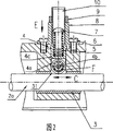
With reference to Fig. 2 to Fig. 5, Fig. 8; Roll wheel assembly 4 is inconsistent through the face of cylinder of regulating retaining mechanism and shank swing span axle 2a; Roll wheel assembly 4 is made up of roller bearing 4a, pin 4b and roller body 4c, and roller body 4c bottom is shaped on board slot, and the top is shaped on spring eye; Roller bearing 4a packs into, and board slot is interior also to be installed through pin 4b, and roller bearing 4a can rotate around pin 4b.Cover 3 radially is shaped on through hole 31 with frame 1 behind the shank swing span, overlaps 3 inner chambers behind this through hole 31 and the shank swing span and communicates, roll wheel assembly 4 this through hole 31 of packing into.Regulating retaining mechanism is made up of locking nut 9, adjustment screw 10, spring guide pillar 7, installing rack 8 and spring 5; Installing rack 8 bottoms are dull and stereotyped, and top is cylinder, and this cylinder runs through base platform; Installing rack 8 bottoms are installed in frame through hole 31 ports through screw 6, and limiting roller group 4 skids off.Spring 5 is placed in spring guide pillar 7 and in the tube of installing rack 8, inserts; Spring 5 bottoms are positioned at the spring eye of roller body 4c; Adjustment screw 10 rotates in the tube of installing rack 8; The cap head of the bottom of adjustment screw 10 and spring guide pillar 7 is conflicted, and locking nut 9 is positioned at installing rack 8 outsides and rotation set in adjustment screw 10, and said structure forms the adjusting retaining mechanism that can change roller bearing 4a loading force.Roller bearing 4a cylindrical contacts with the shank swing span axle 2a face of cylinder under the effect of spring 5 elastic force, and the reciprocating motion of the shank swing span axle 2a left and right sides drives roller bearing 4a and rotates thereupon, and the rotary middle spindle of roller bearing 4a is vertical with shank swing span axle 2a.Adjustment screw 10 on the installing rack 8 can regulating spring 5 pressure, and spring guide pillar 7 can play the effect of guiding to spring 5 compressions, flexural deformation when can prevent spring 5 compressions, and locking nut 9 is locked screw 10 after screw 10 is adjusted.
Roller bearing 4a receives loading force F under the effect of spring 5 elastic force, shank swing span axle 2a side-to-side movement drives roller bearing 4a rotation, and roller bearing 4a has just given shank swing span axle 2a resistance to rolling F1 like this.Same under the effect of loading force F, cover 3 also can produce resistance to sliding F2 behind shank swing span axle 2a and the shank swing span.The resistance of motion F3=FI+F2 of shank swing span axle 2a through adjustment spring 5 elastic force, just can adjust the reciprocating motion resistance of shank swing span axle 2a.In order to reduce wear, can also behind the shank swing span, overlap 3, roll wheel assembly 4 improves greasy property with the contact gap repack with grease of shank rocker axle 2a.
With reference to Fig. 6, Fig. 7; For preventing roll wheel assembly 4 rotations; The through hole 31 of frame 1 is processed into square, and the top cylinder of roller body 4c is cut edge everywhere, just with square through hole 31 form fit; Roller body 4c through hole 31 relatively radially rotates, and guarantees that the rotary middle spindle of roller 4 is vertical with shank swing span axle 2a.
With reference to Figure 10, regulate the spring guide pillar of retaining mechanism and process one with the adjustment screw, promptly adjusting screw 10a is not one or two section formation of external diameter; The epimere external diameter is big and be shaped on external screw thread; Be equivalent to adjust screw, the hypomere external diameter is little, is equivalent to spring guide pillar; Adjustment screw 10a not only can play the effect of guide pillar but also can play the effect of regulating spring 5 elastic force like this, can also reduce the difficulty of processing of part.
Also can repack cover 3 behind the shank swing span into two linear motion bearing 3a; Linear motion bearing 3a and shank swing span axle 2a produce rolling friction like this; Make that cover 3a is reduced to minimum with the monolateral eccentric wear of shank swing span axle 2a behind the shank swing span, thus the service life of raising part.
With reference to Figure 11, also can shank swing span protheca 3 and shank swing span protheca 17 be exchanged, be about to the shank swing span protheca position that rolling wheel regulator installs to left end, the effect of adjustment is the same like this.
With reference to Figure 12; The rolling wheel regulator that another example is implemented comprises eccentric shaft 27, back-up ring screw 28, rolling bearing 29, shaft block ring 30; Rolling wheel regulator before and after the axle sleeve shank swing span cover 17, between 3, rolling bearing 29 is conflicted with shank swing span axle 2a.
With reference to Figure 13 to Figure 16, frame 1 is shaped on through hole, and 32, through hole 32 is vertical with shank swing span axle 2a.Eccentric shaft 27 is made up of big footpath section 27a and path section 27b, and wherein big footpath section 27a is assemblied in the through hole 32, is fixed by screw 28; Path section 27b is eccentric to be provided with, and eccentric throw is t, and section 27a side, big footpath is shaped on regulates groove 27.1 and maximum eccentric concave point B; This concave point B is sign; Make things convenient for the user to operate, rolling bearing 29 is placed in path section 27b, and fixing through shaft block ring 30.
The face of cylinder of the cylindrical of rolling bearing 29 and shank swing span axle 2a is inconsistent; Shank swing span axle 2a left and right sides reciprocating motion (c direction) drive rolling bearing 29 is done the V direction and is back and forth rotated (shown in figure 12), and rolling bearing 29 rotations are vertical with shank swing span axle 2a.If need adjustment rolling bearing 29 loading forces, unclamp screw 28 earlier, just can adjust the loading force of rolling bearing 29 through rotation eccentric axis 27, eccentric shaft 27 more past maximum eccentric concave point B directions are rotated, and revolving force is big more, and the loading force of rolling bearing 29 will be big more.The loading force of adjustment rolling bearing 29 that so just can be suitable as required, last lock-screw 28.Regulate the loading force of rolling bearing 29, just can change the rolling frictional resistance of rolling bearing 29 and shank swing span axle 2a.
Cover 3 and shank swing span protheca 14 play the effect of supporting behind the shank swing span in this device; The loading force of adjustment rolling bearing; Cover 3 also can change with 14 pairs of shank swing spans of shank swing span protheca axle 2a resistance to sliding behind the shank swing span, and the rolling bearing loading force is big more, and resistance to sliding is also just big more; On the contrary, resistance to sliding is also just more little.Cover 3 also can adopt linear bearing with shank swing span protheca 14 behind the same shank swing span; Adjust the load of rolling bearing so; Just can adjust the resistance to rolling of cover 3 and 14 pairs of shank swing spans of shank swing span protheca axle behind the shank swing span; Step motor drive shank swing span 2 reciprocating load forces just can be controlled in certain scope like this, and both are relatively stable.