CN101326857B - Method for operating an induction heating device - Google Patents
Method for operating an induction heating device Download PDFInfo
- Publication number
- CN101326857B CN101326857B CN2006800463562A CN200680046356A CN101326857B CN 101326857 B CN101326857 B CN 101326857B CN 2006800463562 A CN2006800463562 A CN 2006800463562A CN 200680046356 A CN200680046356 A CN 200680046356A CN 101326857 B CN101326857 B CN 101326857B
- Authority
- CN
- China
- Prior art keywords
- voltage
- transistor
- intermediate circuit
- induction coil
- wave
- Prior art date
- Legal status (The legal status is an assumption and is not a legal conclusion. Google has not performed a legal analysis and makes no representation as to the accuracy of the status listed.)
- Active
Links
Images


Classifications
-
- H—ELECTRICITY
- H05—ELECTRIC TECHNIQUES NOT OTHERWISE PROVIDED FOR
- H05B—ELECTRIC HEATING; ELECTRIC LIGHT SOURCES NOT OTHERWISE PROVIDED FOR; CIRCUIT ARRANGEMENTS FOR ELECTRIC LIGHT SOURCES, IN GENERAL
- H05B6/00—Heating by electric, magnetic or electromagnetic fields
- H05B6/02—Induction heating
- H05B6/06—Control, e.g. of temperature, of power
- H05B6/062—Control, e.g. of temperature, of power for cooking plates or the like
Landscapes
- Physics & Mathematics (AREA)
- Electromagnetism (AREA)
- Inverter Devices (AREA)
- General Induction Heating (AREA)
- Control Of High-Frequency Heating Circuits (AREA)
- Rectifiers (AREA)
Abstract
Description
技术领域和现有技术Technical field and prior art
本发明涉及根据权利要求1前序部分的用来操作感应加热设备的方法。The invention relates to a method for operating an induction heating device according to the preamble of claim 1 .
在感应加热设备中,感应线圈被施加交流电压或交流电流,由此涡电流在与感应线圈磁性耦合的需要加热的烹饪用具中被感应。涡电流导致烹饪用具的加热。In an induction heating device, an induction coil is applied with an alternating voltage or an alternating current, whereby eddy currents are induced in the cooking utensil to be heated, which is magnetically coupled to the induction coil. The eddy currents cause heating of the cooking utensil.
控制感应线圈的各种电路设置和控制方法为人所熟知。所有的电路或方法的变体都具有共同点,即为感应线圈从低频的网络输入电压产生高频的控制电压。这样的电路被称为变流器(Umrichter)。Various circuit arrangements and control methods for controlling induction coils are well known. All circuit or method variants have in common that a high-frequency control voltage is generated for an induction coil from a low-frequency network input voltage. Such a circuit is called a converter (Umrichter).
为了变流或变频,通常网络输入电压首先通过整流器被整流为供给直流电压或中间电路电压,随后通过一个或多个开关元件,通常是绝缘栅双极晶体管(IGBT),被处理来产生高频的控制电压。在整流器的输出处,也就是在中间电路电压和参考电势之间,一般设置有所谓的中间电路电容器(Zwischenkreiskondensator)来缓冲中间电路电压。For conversion or frequency conversion, usually the network input voltage is first rectified by a rectifier to a supply DC voltage or an intermediate circuit voltage, which is then processed by one or more switching elements, usually insulated gate bipolar transistors (IGBTs), to generate high frequency the control voltage. At the output of the rectifier, ie between the intermediate circuit voltage and the reference potential, so-called intermediate circuit capacitors are generally arranged to buffer the intermediate circuit voltage.
第一种变流器变体在全桥电路中形成变流器,其中在两个所谓的半桥之间串联耦合(einschleifen)有感应线圈和电容器。所述半桥相应地耦合在中间电路电压和参考电势之间。感应线圈和电容器形成串联谐振电路。A first converter variant forms a converter in a full-bridge circuit, in which an induction coil and a capacitor are coupled in series between two so-called half-bridges. The half bridges are correspondingly coupled between the intermediate circuit voltage and the reference potential. The induction coil and capacitor form a series resonant circuit.
另一种变流器变体由两个IGBT形成半桥电路,其中串联耦合在中间电路电压和参考电势之间的感应线圈和电容器形成串联谐振电路。感应线圈在一端被连接到两个电容器的连接点,在另一端连接到两个形成半桥的IGBT的连接点。Another converter variant consists of two IGBTs forming a half-bridge circuit, in which an induction coil and a capacitor coupled in series between the intermediate circuit voltage and the reference potential form a series resonant circuit. The induction coil is connected at one end to the connection point of the two capacitors and at the other end to the connection point of the two IGBTs forming a half bridge.
具有全桥的变体及具有半桥的变体由于需要大量必需的组件,特别是IGBT,相对来说比较昂贵。The variant with a full bridge and the variant with a half bridge are relatively expensive due to the large number of necessary components, especially IGBTs.
因此,一种从成本角度优化的变体仅仅使用一个开关元件或一个IGBT,其中感应线圈和电容器形成并联谐振电路。在整流器的输出端之间并联于中间电路电容器,由感应线圈和电容器形成的并联谐振电路与IGBT串联耦合。A cost-optimized variant therefore uses only one switching element or one IGBT, where the induction coil and capacitor form a parallel resonant circuit. Between the output terminals of the rectifier in parallel with the intermediate circuit capacitor, a parallel resonant circuit formed by the induction coil and the capacitor is coupled in series with the IGBT.
所有所谓的变流器变体都具有相同点,即在第一网络半波期间,以峰值网络交流电压充电中间电路电容器至空载电压,例如在230V的网络交流电压时至325V,只要能够以网络电压(Netzspannung)来供给。All so-called converter variants have the same point that during the first half-wave of the network, the intermediate circuit capacitors are charged with the peak network AC voltage to the no-load voltage, e.g. Network voltage (Netzspannung) to supply.
如果没有产生用来生成感应线圈功率的控制电压,也就是开关元件或IGBT被抑制,在中间电路电容器处的电压大致保持不变。在变流器的开始,也就是如果用来产生可调加热功率(Heizleistung)的感应线圈被控制,或加载交流电压,则高电流在IGBT接通时首先从中间电路电容器流出至谐振电路,且流经IGBT。这在通过感应加热设备来加热的烹饪用具中造成听得见的噪音,例如在锅底中。此外,加载高接通电流的组件的使用寿命会降低。If no control voltage is generated for generating the power to the induction coil, ie the switching element or the IGBT is suppressed, the voltage at the intermediate circuit capacitor remains approximately constant. At the beginning of the converter, i.e. if the induction coil for generating the adjustable heating power (Heizleistung) is controlled, or an AC voltage is applied, a high current first flows from the intermediate circuit capacitor to the resonant circuit when the IGBT is switched on, and flow through the IGBT. This causes audible noise in cooking appliances heated by induction heating devices, for example in the bottom of a pan. In addition, the service life of components subjected to high inrush currents is reduced.
任务和解决方案tasks and solutions
因此,所述发明的任务在于,提供用来操作带有变流器的感应加热设备的方法,使得以低干扰辐射来可靠地、组件保护地及低噪音地操作感应加热设备成为可能。It is therefore the object of the said invention to provide a method for operating an induction heating system with a current converter, which makes possible a reliable, component-safe and low-noise operation of the induction heating system with low interference emissions.
所述发明通过具有权利要求1特征的方法来解决这个任务。对所述发明有利和优选的扩展则是从属权利所要求的,将在下面进一步说明。权利要求的用词明确地作为描述内容的一部分。The invention solves this object by means of a method with the features of claim 1 . Advantageous and preferred developments of the invention are claimed in the dependent claims and will be explained further below. The wording of the claims is expressly part of the description.
按照所述发明,在控制感应线圈来产生可调节的加热功率前,在网络交流电压的过零点前的在一段时间范围内,中间电路电容器通过控制开关元件来放电至阈值,其中在放电时,必要的话已经在可用的烹饪用具中提供微量的加热功率供给。中间电路电容器的放电导致在加热过程开始时,也就是在感应线圈加热功率应该在烹饪用具提供时,中间电路电容器实质上被放电。如果在这个时候开关元件导通或变的可传导,则不产生或仅仅产生通过开关元件和由感应线圈和电容器组成的谐振电路的小电流脉冲。所以不产生接通噪音,功率组件的脉冲电流负载被降低,由此使用寿命提高。在中间电路电容器放电后,真实的加热过程可以以常规的方式发生,例如开关元件可以由带有工作频率和相应占空比的方波信号来控制。因此,变流器由在过零点范围内的小电流或电压来启动。随着半波在过零点后的提高,变流器可以由工作频率和占空比来调整到其与相应工作点相关的调节加热功率。According to said invention, before the induction coil is controlled to generate an adjustable heating power, the intermediate circuit capacitor is discharged to a threshold value by controlling the switching element within a certain period of time before the zero crossing of the AC voltage of the network, wherein during discharging, If necessary, a slight supply of heating power is already provided in the cooking appliances available. The discharge of the intermediate circuit capacitor results in the intermediate circuit capacitor being substantially discharged at the start of the heating process, ie when the induction coil heating power is to be supplied at the cooking appliance. If at this time the switching element is conducting or becomes conductive, no or only small current pulses are generated through the switching element and the resonant circuit consisting of the induction coil and the capacitor. As a result, switching noises do not occur, the pulse current load of the power components is reduced, and thus the service life is increased. After the intermediate circuit capacitor has been discharged, the actual heating process can take place in a conventional manner, for example the switching element can be controlled by a square-wave signal with operating frequency and corresponding duty cycle. Therefore, the converter is started by a small current or voltage in the range of zero crossings. As the half-wave increases after the zero crossing, the converter can be adjusted to its regulated heating power in relation to the corresponding operating point by means of the operating frequency and the duty cycle.
在其它实现中,变流器是单晶体管变流器。在这里,至少一个开关元件优选为形成单晶体管变流器的开关元件。备选的,变流器在全桥电路或半桥电路中被实现,其中至少一个开关元件是桥的一部分。In other implementations, the converter is a single transistor converter. Here, the at least one switching element is preferably a switching element forming a single-transistor converter. Alternatively, the converter is realized in a full bridge circuit or a half bridge circuit, wherein at least one switching element is part of the bridge.
在还有的实现中,在网络交流电压的过零点前的时间范围从1ms开始至5ms,优选2.5ms。这使中间电路电容器的可靠放电成为可能,同样可以使开关元件中通过放电过程产生损耗功率变小。In yet another implementation, the time before the zero crossing of the AC voltage of the network ranges from 1 ms to 5 ms, preferably 2.5 ms. This enables a reliable discharge of the intermediate circuit capacitor and also reduces the power loss in the switching element due to the discharge process.
在还有的实现中,阈值在从0V至20V的范围内。中间电路电容器优选地放电至0V。这使变流器的实际无脉冲电流启动成为可能。In yet other implementations, the threshold ranges from 0V to 20V. The intermediate circuit capacitor is preferably discharged to 0V. This enables practical pulse-free starting of the converter.
在又一实现中,至少一个开关元件是晶体管,特别是IGBT。为了放电中间电路电容器,晶体管优选在放电期间被控制,调节到线性工作状态。因此,如果在这种工作类型或者这种工作状态下的晶体管没有充分导通,则中间电路电容器缓慢沿网络半波放电。通过并联谐振电路和晶体管产生的电流保持相对较小,由此噪音的发出被避免或显著降低。In yet another implementation, at least one switching element is a transistor, in particular an IGBT. In order to discharge the intermediate circuit capacitors, the transistors are preferably controlled during the discharge to a linear operating state. Therefore, if the transistors in this type of operation or in this operating state are not sufficiently conductive, the intermediate circuit capacitors are slowly discharged along the network half-wave. The current generated by the parallel resonant circuit and the transistor is kept relatively small, whereby the emission of noise is avoided or significantly reduced.
在还有的实现中,为了放电中间电路电容器,开关元件由带有脉冲宽度调制的方波电压信号来控制。方波电压信号优选为具有从20kHz至50kHz范围内的频率,特别是39kHz,和/或从1/300至1/500范围内的通/断比例(An/Aus-Verhaeltnis),特别是1/378。用这种方法,可以引起被控制的中间电路电容器的放电,而不需流过太大的放电电流。频率和/或通/断比例首先匹配于使用的IGBT类型、其驱动电压、用来产生驱动电压的所使用的驱动电路、和/或中间电路电容器的电容值。In a further implementation, the switching element is controlled by a square-wave voltage signal with pulse width modulation for discharging the intermediate circuit capacitor. The square-wave voltage signal preferably has a frequency in the range from 20 kHz to 50 kHz, in particular 39 kHz, and/or an on/off ratio (An/Aus-Verhaeltnis) in the range from 1/300 to 1/500, in particular 1/ 378. In this way, it is possible to bring about a discharge of the controlled intermediate circuit capacitor without having to flow a large discharge current. The frequency and/or the on/off ratio are firstly matched to the type of IGBT used, its drive voltage, the drive circuit used to generate the drive voltage, and/or the capacitance value of the intermediate circuit capacitor.
在还有另一实现中,可调节的加热功率由半波模式(Halbwellenmuster)来产生,其中中间电路电容器在半波激活前被放电。在由半波模式产生加热功率时,网络交流电压的单个半波被减弱或去激活,也就是不被用来产生加热功率。在所谓的1/3-网络半波操作中,为了供给功率到谐振电路或感应线圈中,例如三个互相跟随的半波中的仅仅一个被使用或激活。在剩下的两个半波期间,开关元件保持被打开,也就是没有功率被供给到谐振电路中。在2/3-网络半波操作中,为了供给功率到谐振电路或感应线圈中,三个互相跟随的半波中的两个被使用或激活。在激活的半波期间,功率调节以常规的方式发生。网络半波操作使在大功率调节范围内的功率等级的优良精度成为可能。这样的功率调节特别对单晶体管变流器非常有利。如果在单晶体管变流器的常规操作方法中,为了调节功率而使用半波操作,在一个非激活半波期间,也就是在一个半波期间,没有功率被供给到谐振电路中,空载电压在中间电路电容器处被调节,例如在230V网络电压时为325V。In yet another implementation, the adjustable heating power is generated by the half-wave mode, in which the intermediate circuit capacitor is discharged before the half-wave activation. When generating the heating power in the half-wave mode, the individual half-waves of the AC voltage of the network are attenuated or deactivated, ie are not used to generate the heating power. In so-called 1/3-network half-wave operation, for example only one of three mutually following half-waves is used or activated for supplying power into the resonant circuit or induction coil. During the remaining two half-waves, the switching element remains open, ie no power is supplied into the resonant circuit. In 2/3-network half-wave operation, two of the three mutually following half-waves are used or activated for supplying power into the resonant circuit or induction coil. During the active half-wave, power regulation occurs in a conventional manner. Network half-wave operation enables excellent accuracy of power levels over a large power regulation range. Such power regulation is particularly advantageous for single-transistor converters. If, in the conventional method of operation of single-transistor converters, half-wave operation is used for power regulation, during an inactive half-wave, that is, during a half-wave, no power is supplied to the resonant circuit, the no-load voltage Regulated at the intermediate circuit capacitor, for example 325V at 230V network voltage.
如果在从非激活到激活半波的过渡期间,开关元件最初被导通,则高电流短暂地流过谐振电路和开关元件,由此,就像已经实施的会导致噪音。在1/3-和2/3-网络半波操作中,用这种方法,每30ms产生一次噪音。这不是使用者要求的。因此,在常规的单晶体管变流器中,一般没有半波控制为了调节功率而被使用。在中间电路电容器在激活半波前按照所述发明放电的使用中,也就是从被去激活半波到被激活半波的过渡期间,没有高接通电流产生,也就是在单晶体管变流器中,也可以为了功率调节而使用半波控制。三个半波中的一个或两个被优选激活,也就是设定为1/3或2/3网络半波操作。If the switching element is initially switched on during the transition from inactive to active half-wave, a high current briefly flows through the resonant circuit and the switching element, which, as already implemented, can lead to noise. In 1/3- and 2/3-network half-wave operation, noise is generated every 30 ms in this way. This is not what the user requested. Therefore, in conventional single-transistor converters, generally no half-wave control is used for power regulation. In the use of the discharge of the intermediate circuit capacitor according to the described invention before the activation half-wave, ie during the transition from the deactivated half-wave to the activated half-wave, no high inrush currents occur, ie in single-transistor converters In , half-wave control can also be used for power regulation. One or two of the three half-waves are preferably activated, ie set to 1/3 or 2/3 network half-wave operation.
除了来自于权利要求,这些和其他特征也来自于说明书和附图,其中单个特征相应地以单独或多个的子组合形式在本发明的实施方式和其它领域实现,并且为此优选地表现为在此请求保护的可保护的实施方式。将申请分为多个部分及中间的标题并不在整体上限制下面的描述。Apart from the claims, these and other features also result from the description and the drawings, wherein the individual features are respectively realized individually or in multiple sub-combinations in the embodiment of the invention and in other fields, and for this purpose are preferably expressed as Protectable embodiments claimed herein. The division of the application into sections and intermediate headings does not limit the following description as a whole.
附图简述Brief description of the drawings
所述发明的实现形式在附图中被概要地描绘,在下面被进一步说明。在这里显示:Implementations of the invention are schematically depicted in the drawings and further described below. Shown here:
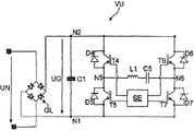
图1单晶体管变流器的电路图,其由按照发明的操作方法来驱动,Fig. 1 Circuit diagram of a single-transistor converter driven by the method of operation according to the invention,
图2图1的单晶体管变流器的信号时间流程图,Fig. 2 Signal time flow diagram of the single transistor converter of Fig. 1,
图3在半桥电路中的变流器的电路图,其由按照发明的操作方法来驱动,和3 is a circuit diagram of a converter in a half-bridge circuit driven by the method of operation according to the invention, and
图4在全桥电路中的变流器的电路图,其由按照发明的操作方法来驱动。FIG. 4 is a circuit diagram of a converter in a full bridge circuit, which is driven by the operating method according to the invention.
具体实施方式Detailed ways
图1显示了单晶体管变流器EU形式的感应加热设备的电路图。感应加热设备也可以包括其它未显示出来的相同构造的单晶体管变流器EU和附加常规部件,例如用来调节功率的控制元件等。Figure 1 shows the circuit diagram of an induction heating device in the form of a single-transistor converter EU. The induction heating device can also comprise further, not shown, identically constructed single-transistor converters EU and additional conventional components, such as control elements for regulating the power, etc.
单晶体管变流器EU包括由230V和50Hz的输入网络交流电压UN中产生中间电路直流电压UG的桥整流器GL、耦合整流器GL的输出端N1和N2之间的用来稳定或缓冲中间电路直流电压UG的缓冲器或中间电路电容器C1、并联且形成并联谐振电路感应线圈L1和电容器C2、与谐振电路串联耦合在整流器GL的输出端N1和N2之间IGB-晶体管T1形式的可控开关元件、并联连接至IGB-晶体管T1的集电极-发射极-区间的空载二极管D1、和例如以微处理器或数字信号处理器的形式出现的控制单元SE。The single-transistor converter EU includes a bridge rectifier GL that generates an intermediate circuit DC voltage UG from an input network AC voltage UN of 230V and 50Hz, and a bridge rectifier GL between the output terminals N1 and N2 of the coupling rectifier GL for stabilizing or buffering the intermediate circuit DC voltage A buffer or intermediate circuit capacitor C1 of the UG, an induction coil L1 and a capacitor C2 connected in parallel and forming a parallel resonant circuit, a controllable switching element in the form of an IGB-transistor T1 coupled in series with the resonant circuit between the output terminals N1 and N2 of the rectifier GL, An idler diode D1 connected in parallel to the collector-emitter-interval of the IGB-transistor T1, and a control unit SE, for example in the form of a microprocessor or a digital signal processor.
为了操作单晶体管变流器EU,控制元件SE实现按照发明的在下文中相对于图2描述的操作方法,还可以包括或被耦合至其它的未显示的执行器和/或传感器,例如用来监控网络电压变化。In order to operate the single-transistor converter EU, the control element SE implements the operating method according to the invention described hereinafter with respect to FIG. Network voltage changes.
图2显示了图1的单晶体管变流器EU的信号的未按照原尺寸的时间流程图。根据50Hz的输入网络交流电压UN的网络频率(Netzfrequenz),在输入网络交流电压UN的相邻网络半波H1至H3之间每10ms出现一次过零点。单晶体管变流器EU在2/3-网络半波操作中被控制,也就是仅在三个网络半波的两个期间功率被供给到并联谐振电路或感应线圈L1中。在图2中,半波H2和H3是激活半波,在此期间功率被供给,网络半波H1是非激活半波,在此期间没有功率供给发生。在非激活半波H1期间,IGB-晶体管T1禁止,直至过渡范围或预定放电范围INT,在此期间中间电路电容器C1被放电。FIG. 2 shows a non-scaled time diagram of the signals of the single-transistor converter EU of FIG. 1 . Depending on the network frequency (Netzfrequenz) of the AC input network voltage UN of 50 Hz, a zero crossing occurs every 10 ms between adjacent network half-waves H1 to H3 of the AC input network voltage UN. The single-transistor converter EU is controlled in 2/3-network half-wave operation, ie power is supplied to the parallel resonant circuit or induction coil L1 only during two of the three network half-waves. In Figure 2, half-waves H2 and H3 are active half-waves, during which power is supplied, and network half-wave H1 is an inactive half-wave, during which no power supply occurs. During the inactive half-wave H1, the IGB-transistor T1 is disabled until the transition range or predetermined discharge range INT, during which the intermediate circuit capacitor C1 is discharged.
UC是IGB-晶体管T1的集电极处的电压,其相对于整流器GL的端口N1处的参考电势。在非激活半波期间,在被禁止的IGB-晶体管T1上,空载电压在集电极处为网络交流电压UN的峰值,也就是在显示的实施例中为大约325V。UC is the voltage at the collector of the IGB-transistor T1 relative to the reference potential at the port N1 of the rectifier GL. During the inactive half-wave, at the collector of the disabled IGB transistor T1 , the no-load voltage is the peak value of the AC network voltage UN, ie approximately 325 V in the exemplary embodiment shown.
在激活半波H2和H3期间,功率被供给到感应线圈L1中。这可以以常规的方式引起,例如由带有频率和占空比的方波电压信号来控制IGB-晶体管T1,其取决于在半波期间被调节的供给功率。During activation of the half-waves H2 and H3, power is supplied to the induction coil L1. This can be brought about in a conventional manner, for example by controlling the IGB-transistor T1 by a square-wave voltage signal with frequency and duty cycle, which depends on the regulated supply power during the half-wave.
为了消除从半波H1至半波H2过渡的接通电流脉冲,在放电时间范围或时间间隔INT期间,大约在半波H1和H2之间的过零点ND之前2.5ms的时间点T0和过零点ND之间,中间电路电容器C1开始通过控制IGB-晶体管来连续放电直至大约0V。另外,IGB-晶体管T1由带有大约39kHz的频率和大约1/378的通/断比例的未显示方波电压信号来控制。控制脉冲很短,以致于不足以去除IGB-晶体管-门的电荷。因此,IGB-晶体管T1没有充分导通,而是以线性操作方式。IGB-晶体管T1的集电极处的电压UC,其在这种情况下相关于中间电路电容器C1处的电压UG,就如显示的,通过缓慢沿网络半波作为包络曲线下降至大约0V。在图2显示的部分扩展中显示带有更大时间分辨率的信号UC。由此,大约39kHz的IGBT导通频率在放电过程中是可见的。In order to eliminate the switch-on current pulse for the transition from half-wave H1 to half-wave H2, during the discharge time range or time interval INT, the time point T0 and the zero-crossing point approximately 2.5 ms before the zero-crossing point ND between half-waves H1 and H2 Between NDs, the intermediate circuit capacitor C1 starts to discharge continuously up to about 0V by controlling the IGB-transistor. In addition, the IGB-transistor T1 is controlled by a not shown square wave voltage signal with a frequency of about 39 kHz and an on/off ratio of about 1/378. The control pulse is so short that it is not sufficient to decharge the IGB-transistor-gate. Therefore, the IGB-transistor T1 is not sufficiently turned on, but operates in a linear manner. The voltage UC at the collector of the IGB transistor T1 , which in this case is related to the voltage UG at the intermediate circuit capacitor C1 , drops to approximately 0 V by slowly following the network half-wave as an envelope, as shown. In the partial expansion shown in FIG. 2 , signal UC is shown with greater temporal resolution. Thus, an IGBT conduction frequency of approximately 39kHz is visible during discharge.
因为IGBT T1被不充分传导或导通,只出现通过感应线圈L1的小电流。因此,由线圈电流引起的噪音被阻止或显著降低。Because the IGBT T1 is not sufficiently conducted or turned on, only a small current through the induction coil L1 occurs. As a result, noise caused by coil currents is blocked or significantly reduced.
在半波H2和H3期间,带有未显示的方波电压信号的IGB-晶体管T1以常规的方式被控制。在图2中显示了产生电压UC的包络曲线和带有更大时间分辨率的信号UC的放大图。电压UC由于并联谐振电路中的振荡而上升至明显高于空载电压。包络曲线显示正弦过程的曲线,其跟随被整流的输入网络交流电压UN。被显示的电压UC曲线在半波H3期间反复。IGBT T1的控制信号的频率在这种操作情况下在大约22kHz处。During the half-waves H2 and H3, the IGB-transistor T1 is controlled in a conventional manner with a square-wave voltage signal not shown. FIG. 2 shows the envelope curve of the resulting voltage UC and an enlarged view of the signal UC with greater temporal resolution. The voltage UC rises significantly above the no-load voltage due to oscillations in the parallel resonant circuit. The envelope curve shows the curve of a sinusoidal process, which follows the rectified input network AC voltage UN. The displayed voltage UC curve repeats during the half-wave H3. The frequency of the control signal of IGBT T1 is at about 22 kHz in this operating case.
在未显示的跟随半波H3的半波期间,IGB-晶体管T1被去激活,由此电压UC再次上升至大约325V的空载值。在过渡到后续的激活的半波期间,放电过程重复,就像为半波H1显示的。被描述的过程周期地重复。During a not-shown half-wave following half-wave H3 , IGB transistor T1 is deactivated, whereby voltage UC rises again to a no-load value of approximately 325 V. During the transition to the subsequent active half-wave, the discharge process repeats, as shown for half-wave H1. The described process is repeated periodically.
所以,变流器电路可以由小电压和电流来启动,随着网络半波的提高调整至其本来的来自合适的频率和占空比的工作点。Therefore, the converter circuit can be started from a small voltage and current, and adjusted to its original operating point from a suitable frequency and duty cycle as the half-wave of the network increases.
为了在线性工作的放电期间控制IGB-晶体管,取决于被使用的IGB-晶体管,放电频率和占空比可以匹配于用来控制使用的控制电压、中间电路电容器的容量和谐振电路的尺寸。In order to control the IGB-transistor during discharge in linear operation, the discharge frequency and duty cycle can be matched to the control voltage used for control, the capacity of the intermediate circuit capacitor and the size of the resonant circuit, depending on the IGB-transistor used.
如所示的,通过按照本发明的中间电路电容器的放电,由单晶体管变流器EU的半波模式来控制功率而不引起噪音干扰是可能的。如果在这种情况下,功率应该在一个半波内被供给,中间电路电容器在之前的非激活半波的最后被放电。这使大功率调节范围成为可能,而接通电流最高点不需要过度加负载于IGB-晶体管T1。总之,因此,组件的使用寿命提高。As shown, through the discharge of the intermediate circuit capacitor according to the invention, it is possible to control the power by the half-wave mode of the single-transistor converter EU without causing noise disturbances. If in this case power is to be supplied within a half-wave, the intermediate circuit capacitor is discharged at the end of the preceding inactive half-wave. This enables a large power regulation range without excessive loading of the IGB-transistor T1 at the peak of the on-current. Overall, therefore, the service life of the components is increased.
图3显示了半桥电路中的变流器HU的电路图,其由按照发明的操作方法来控制。与图1中功能相同的组件具有相等的附图标记。鉴于此,其功能性描述参考图1。FIG. 3 shows a circuit diagram of a converter HU in a half-bridge circuit, which is controlled by the operating method according to the invention. Components with the same function as in Fig. 1 have the same reference numerals. In view of this, its functional description refers to FIG. 1 .
半桥由IGBT T2和T3组成,串联耦合在整流器GL的输出端N1和N2之间。空载二极管D2或D3并联连接至IGBT T2或T3的相应集电极-发射极-区间。电容器C3和C4同样串联耦合在输出端N1和N2之间。在IGBT T2和T3的连接节点N3和电容器C3和C4的连接节点N4之间,耦合有感应线圈L1。L1与电容器C3和C4一起形成串联谐振电路。The half-bridge consists of IGBTs T2 and T3 coupled in series between the outputs N1 and N2 of the rectifier GL. The free-wheeling diode D2 or D3 is connected in parallel to the corresponding collector-emitter-section of the IGBT T2 or T3. Capacitors C3 and C4 are also coupled in series between output terminals N1 and N2. Between the connection node N3 of the IGBTs T2 and T3 and the connection node N4 of the capacitors C3 and C4, an induction coil L1 is coupled. L1 together with capacitors C3 and C4 form a series resonant circuit.
IGBT T2和T3由控制元件SE来控制。功率调节可以用常规的方式发生,例如通过调整由控制元件SE产生的IGBT的控制信号的频率。IGBT T2 and T3 are controlled by control element SE. Power regulation can take place in a conventional manner, eg by adjusting the frequency of the control signal of the IGBT generated by the control element SE.
在接通变流器HU之后和产生加热功率之前,中间电路电容器C1和电容器C3和C4通过控制IGBT T2和T3被放电。这发生类似于图2描述的方法,由带有合适的频率和合适的通/断比例的方波电压信号来控制IGBT T2和T3。在这里,控制脉冲还是很短,以致于不足以去除各个IGB-晶体管-门处的电荷。因此,IGB-晶体管T2和T3没有充分导通,而是处于线性操作方式。After switching on the converter HU and before generating heating power, the intermediate circuit capacitor C1 and the capacitors C3 and C4 are discharged by controlling the IGBTs T2 and T3. This occurs in a manner similar to that described in Figure 2, by controlling the IGBTs T2 and T3 by a square wave voltage signal with a suitable frequency and a suitable on/off ratio. Here again, the control pulses are too short to remove the charges at the individual IGB-transistor gates. Therefore, the IGB-transistors T2 and T3 are not fully turned on, but are in a linear mode of operation.
用这种方法,半桥电路的变流器处的干扰噪声也可以在接通过程或在去激活加热功率之后及随后再激活时被有效地阻止。In this way, interfering noises at the converters of the half-bridge circuit can also be effectively prevented during the switch-on process or after deactivation of the heating power and subsequent reactivation.
图4显示了在全桥电路中的变流器VU的电路图,其由按照发明的操作方法来控制。与图1中功能相同的组件具有相等的附图标记。鉴于此,其功能性描述参考图1。FIG. 4 shows a circuit diagram of a converter VU in a full bridge circuit, which is controlled by the operating method according to the invention. Components with the same function as in Fig. 1 have the same reference numerals. In view of this, its functional description refers to FIG. 1 .
第一半桥由IGBT T4和T5组成,第二半桥由IGBT T6和T7组成,相应地串联耦合在整流器GL的输出端N1和N2之间。空载二极管D4至D7并联连接至IGBT T4至T7的相应集电极-发射极-区间。在IGBT T4和T5的连接节点N5和IGBT T6和T7的连接节点N6之间,串联耦合有感应线圈L1和电容器C5。感应线圈L1与电容器C5形成串联谐振电路。The first half-bridge consists of IGBTs T4 and T5 and the second half-bridge consists of IGBTs T6 and T7, respectively coupled in series between the outputs N1 and N2 of the rectifier GL. The free-wheeling diodes D4 to D7 are connected in parallel to the respective collector-emitter-sections of the IGBTs T4 to T7. Between the connection node N5 of the IGBTs T4 and T5 and the connection node N6 of the IGBTs T6 and T7, an induction coil L1 and a capacitor C5 are coupled in series. The induction coil L1 forms a series resonant circuit with the capacitor C5.
IGBT T4至T7由控制元件SE来控制。功率调节可以以常规的方式发生,例如通过调整由控制元件SE产生的IGBT控制信号的频率。The IGBTs T4 to T7 are controlled by the control element SE. Power regulation can take place in a conventional manner, eg by adjusting the frequency of the IGBT control signal generated by the control element SE.
在接通变流器VU之后和产生加热功率之前,中间电路电容器C1通过控制IGBT T4至T7而被放电。这种情况类似于图2描述的方法,由带有合适的频率和合适的通/断比例的方波电压信号来控制IGBTT4至T7。在这里,控制脉冲还是很短,以致于不足以去除各个IGB-晶体管-门处的电荷。因此,IGB-晶体管T4和T7没有充分导通,而是以线性操作方式。After switching on the converter VU and before generating heating power, the intermediate circuit capacitor C1 is discharged by controlling the IGBTs T4 to T7. This case is similar to the method described in Fig. 2, by a square wave voltage signal with a suitable frequency and a suitable on/off ratio to control IGBT4 to T7. Here again, the control pulses are too short to remove the charges at the individual IGB-transistor gates. Therefore, the IGB-transistors T4 and T7 are not sufficiently turned on, but operate in a linear manner.
为了使中间电路电容器C1放电,所有IGB T4至T7或只有特定的IGB被如此控制,使得形成用来放电中间电路电容器C1的电流通路。例如只有T4和T5,只有T6和T7,只有T4和T7,或只有T6和T5被控制来放电。In order to discharge the intermediate circuit capacitor C1, all IGBs T4 to T7 or only specific IGBs are controlled in such a way that a current path is formed for discharging the intermediate circuit capacitor C1. For example only T4 and T5, only T6 and T7, only T4 and T7, or only T6 and T5 are controlled to discharge.
用这种方法,全桥电路的变流器处的干扰噪声也可以在接通过程或在去激活加热功率之后及随后再次激活时被有效地阻止。In this way, interfering noises at the converters of the full bridge circuit can also be effectively prevented during the switch-on process or after deactivation of the heating power and subsequent reactivation.
在被显示的实施例中,网络电压为230V,网络频率为50Hz。不言而喻,被显示的控制方法也适用于其它网络电压和网络频率。In the example shown, the network voltage is 230V and the network frequency is 50 Hz. It goes without saying that the shown control method is also suitable for other network voltages and network frequencies.
Claims (13)
Applications Claiming Priority (3)
| Application Number | Priority Date | Filing Date | Title |
|---|---|---|---|
| DE102005050038.2 | 2005-10-14 | ||
| DE102005050038A DE102005050038A1 (en) | 2005-10-14 | 2005-10-14 | Method for operating an induction heater |
| PCT/EP2006/009916 WO2007042318A1 (en) | 2005-10-14 | 2006-10-13 | Method for operating an induction heating device |
Publications (2)
| Publication Number | Publication Date |
|---|---|
| CN101326857A CN101326857A (en) | 2008-12-17 |
| CN101326857B true CN101326857B (en) | 2011-11-23 |
Family
ID=37667339
Family Applications (1)
| Application Number | Title | Priority Date | Filing Date |
|---|---|---|---|
| CN2006800463562A Active CN101326857B (en) | 2005-10-14 | 2006-10-13 | Method for operating an induction heating device |
Country Status (10)
| Country | Link |
|---|---|
| US (1) | US8415594B2 (en) |
| EP (1) | EP1935213B1 (en) |
| JP (1) | JP2009512147A (en) |
| CN (1) | CN101326857B (en) |
| AT (1) | ATE422146T1 (en) |
| CA (1) | CA2625765C (en) |
| DE (2) | DE102005050038A1 (en) |
| ES (1) | ES2320594T3 (en) |
| SI (1) | SI1935213T1 (en) |
| WO (1) | WO2007042318A1 (en) |
Families Citing this family (25)
| Publication number | Priority date | Publication date | Assignee | Title |
|---|---|---|---|---|
| ES2398290T3 (en) * | 2007-09-05 | 2013-03-15 | Whirlpool Corporation | Improved induction cooker and method to check the cooking capabilities of a kitchenware piece |
| ES2362523B1 (en) * | 2009-08-27 | 2012-08-02 | BSH Electrodomésticos España S.A. | CONTROL OF AT LEAST ONE INDUCTION HEATING LOAD. |
| DE102009047185B4 (en) * | 2009-11-26 | 2012-10-31 | E.G.O. Elektro-Gerätebau GmbH | Method and induction heating device for determining a temperature of a cooking vessel bottom heated by means of an induction heating coil |
| ES2386456B1 (en) * | 2010-06-28 | 2013-07-19 | BSH Electrodomésticos España S.A. | COOKING HOB DEVICE |
| CN102244949B (en) * | 2011-06-16 | 2013-04-17 | 美的集团股份有限公司 | Method for controlling electromagnetic heating power |
| DE102011083383A1 (en) * | 2011-09-26 | 2013-03-28 | E.G.O. Elektro-Gerätebau GmbH | Method for heating a liquid contained in a cooking vessel and induction heating device |
| KR101170804B1 (en) * | 2012-01-12 | 2012-08-02 | 주식회사 윌링스 | Resonant inverter preventing surging current |
| DE102012207847A1 (en) | 2012-05-10 | 2013-11-14 | Behr-Hella Thermocontrol Gmbh | Device for inductive heating of a radiator |
| CN103731945B (en) * | 2012-10-11 | 2015-12-02 | 美的集团股份有限公司 | Prevent control method and the control circuit of electromagnetic heater failure of oscillation |
| WO2015118636A1 (en) * | 2014-02-06 | 2015-08-13 | 三菱電機株式会社 | Discharging device |
| CN106714352B (en) * | 2015-08-03 | 2019-10-25 | 佛山市顺德区美的电热电器制造有限公司 | Determination method, determination system and electromagnetic heating device of zero-crossing conduction time |
| CN106714353B (en) * | 2015-08-03 | 2019-11-01 | 佛山市顺德区美的电热电器制造有限公司 | The determination method of passing zero trigger time determines system and electromagnetic heater |
| ES2975178T3 (en) * | 2015-12-02 | 2024-07-03 | Ego Elektro Geraetebau Gmbh | Method of operation of an induction cooking hob |
| ES2684175B1 (en) * | 2017-03-30 | 2019-07-12 | Bsh Electrodomesticos Espana Sa | DOMESTIC DEVICE DEVICE AND PROCEDURE FOR THE OPERATION OF A DOMESTIC DEVICE DEVICE |
| CN108668394B (en) * | 2017-03-31 | 2021-10-26 | 佛山市顺德区美的电热电器制造有限公司 | Electromagnetic heating system and starting device and starting method of power switch tube of electromagnetic heating system |
| CN109047786B (en) * | 2018-09-25 | 2020-11-24 | 大连理工大学 | A device and method for efficiently preparing spherical metal powder for 3D printing in fibrous splitting mode |
| EP3768042B1 (en) * | 2019-07-19 | 2022-12-07 | Electrolux Appliances Aktiebolag | Method for controlling the provision of electric power to an induction coil |
| KR102803716B1 (en) * | 2020-04-02 | 2025-05-09 | 엘지전자 주식회사 | Method for discharging capacitor of resonant power conversion apparatus at initiating of operation and resonant power conversion apparatus thereof |
| DE102020207103A1 (en) | 2020-06-05 | 2021-12-09 | E.G.O. Elektro-Gerätebau GmbH | Method for operating an induction hob and induction hob |
| CN113923810B (en) * | 2020-07-08 | 2024-09-06 | 台达电子工业股份有限公司 | Heating device and control method thereof |
| WO2022096122A1 (en) | 2020-11-06 | 2022-05-12 | Intell Properties B.V. | Circuit arrangement for an induction cooker, induction cooker and method for operating an induction cooker |
| US12538391B2 (en) | 2021-01-20 | 2026-01-27 | Lg Electronics Inc. | Induction heating apparatus and method for controlling the same |
| CN115515266B (en) * | 2022-08-19 | 2025-08-22 | 珠海格力电器股份有限公司 | A circuit and method for adjusting output power of electromagnetic coil |
| US11641701B1 (en) * | 2022-08-31 | 2023-05-02 | Techniks, LLC | Electronic protection circuit |
| DE102022210534A1 (en) * | 2022-10-05 | 2024-04-11 | E.G.O. Elektro-Gerätebau GmbH | Device for wirelessly transmitting energy to a consumer by means of inductive coupling |
Citations (4)
| Publication number | Priority date | Publication date | Assignee | Title |
|---|---|---|---|---|
| US4338503A (en) * | 1979-08-03 | 1982-07-06 | Tokyo Shibaura Denki Kabushiki Kaisha | Inductive heating apparatus |
| US4438311A (en) * | 1979-07-05 | 1984-03-20 | Sanyo Electric Co., Ltd. | Induction heating cooking apparatus |
| US5354971A (en) * | 1992-07-15 | 1994-10-11 | Chen Su Min | Dual push-pull heating device of induction cooker having multiple burners |
| CN1482838A (en) * | 2002-06-21 | 2004-03-17 | ���µ�����ҵ��ʽ���� | Power control method and device for high-frequency induction heating |
Family Cites Families (29)
| Publication number | Priority date | Publication date | Assignee | Title |
|---|---|---|---|---|
| US3569810A (en) * | 1968-11-20 | 1971-03-09 | Allis Chalmers Mfg Co | Pulse width modulator with pulse width limiting |
| DE1928757C3 (en) * | 1969-06-06 | 1978-11-23 | Messer Griesheim Gmbh, 6000 Frankfurt | Circuit arrangement for stabilizing and igniting welding arcs |
| US3787756A (en) * | 1973-01-19 | 1974-01-22 | Pioneer Magnetics Inc | Inrush current limiting circuit |
| CH561285A5 (en) * | 1973-02-19 | 1975-04-30 | Berghaus Bernhard Elektrophysi | |
| US4277667A (en) | 1978-06-23 | 1981-07-07 | Matsushita Electric Industrial Co., Ltd. | Induction heating apparatus with negative feedback controlled pulse generation |
| JPS5679991U (en) * | 1979-11-26 | 1981-06-29 | ||
| AU4545585A (en) * | 1984-07-14 | 1986-02-10 | Eckerfeld, A. | Elektrischer durchlauferhitzer mit regelbarer auslauftemperatur und elektronischer leistungssteller dafur |
| JPH0795471B2 (en) * | 1986-07-04 | 1995-10-11 | 松下電器産業株式会社 | Induction heating cooker |
| GB2198296B (en) * | 1986-11-25 | 1990-08-08 | Ti Creda Ltd | Improvements in or relating to induction heating circuits for cooking appliances |
| GB2203605B (en) * | 1987-04-07 | 1991-01-09 | Toshiba Kk | Electromagnetic induction heating apparatus capable of preventing undesirable states of cooking utensils or vessels |
| KR900006795B1 (en) * | 1988-01-29 | 1990-09-21 | 주식회사 금성사 | Driving control method of electronic cooker |
| US5537074A (en) * | 1993-08-24 | 1996-07-16 | Iversen; Arthur H. | Power semiconductor packaging |
| KR940004040B1 (en) * | 1991-10-24 | 1994-05-11 | 주식회사 금성사 | Load Sensing Circuit of Induction Heating Cooker |
| US5526103A (en) * | 1994-03-31 | 1996-06-11 | Minolta Co., Ltd. | Induction heating fixing device |
| US6118186A (en) * | 1994-09-14 | 2000-09-12 | Coleman Powermate, Inc. | Throttle control for small engines and other applications |
| JPH08196077A (en) * | 1994-11-18 | 1996-07-30 | Toshiba Corp | Power converter and air conditioner using the same |
| US5648008A (en) * | 1994-11-23 | 1997-07-15 | Maytag Corporation | Inductive cooking range and cooktop |
| US5731681A (en) * | 1995-06-28 | 1998-03-24 | Hitachi Koki Co., Ltd. | Motor control system for centrifugal machine |
| US6021052A (en) * | 1997-09-22 | 2000-02-01 | Statpower Technologies Partnership | DC/AC power converter |
| EP1250029B1 (en) * | 2000-01-13 | 2010-10-13 | Panasonic Corporation | Induction heating cooker |
| JP2002075622A (en) * | 2000-09-04 | 2002-03-15 | Fuji Electric Co Ltd | Electromagnetic cooker power supply |
| EP1432289A1 (en) * | 2002-12-18 | 2004-06-23 | Harison Toshiba Lighting Corporation | Induction heating roller device for use in image forming apparatus |
| JP2004350493A (en) * | 2003-04-28 | 2004-12-09 | Matsushita Electric Ind Co Ltd | Inverter control device for motor drive and air conditioner using the same |
| JP4148073B2 (en) * | 2003-08-29 | 2008-09-10 | 富士電機機器制御株式会社 | Induction heating device |
| JP4117568B2 (en) * | 2003-09-17 | 2008-07-16 | 三菱電機株式会社 | Induction heating cooker |
| JP4148094B2 (en) * | 2003-10-15 | 2008-09-10 | 松下電器産業株式会社 | Induction heating device |
| DE102005050036A1 (en) * | 2005-10-14 | 2007-05-31 | E.G.O. Elektro-Gerätebau GmbH | Induction heater and associated operation and pan detection method |
| DE102008015036A1 (en) * | 2008-03-14 | 2009-09-17 | E.G.O. Elektro-Gerätebau GmbH | Apparatus and method for controlling induction heating of an induction hob |
| DE102009047185B4 (en) * | 2009-11-26 | 2012-10-31 | E.G.O. Elektro-Gerätebau GmbH | Method and induction heating device for determining a temperature of a cooking vessel bottom heated by means of an induction heating coil |
-
2005
- 2005-10-14 DE DE102005050038A patent/DE102005050038A1/en not_active Withdrawn
-
2006
- 2006-10-13 WO PCT/EP2006/009916 patent/WO2007042318A1/en not_active Ceased
- 2006-10-13 EP EP06806263A patent/EP1935213B1/en active Active
- 2006-10-13 SI SI200630281T patent/SI1935213T1/en unknown
- 2006-10-13 AT AT06806263T patent/ATE422146T1/en not_active IP Right Cessation
- 2006-10-13 JP JP2008534942A patent/JP2009512147A/en active Pending
- 2006-10-13 DE DE502006002762T patent/DE502006002762D1/en active Active
- 2006-10-13 ES ES06806263T patent/ES2320594T3/en active Active
- 2006-10-13 CN CN2006800463562A patent/CN101326857B/en active Active
- 2006-10-13 CA CA2625765A patent/CA2625765C/en not_active Expired - Fee Related
-
2008
- 2008-04-11 US US12/101,419 patent/US8415594B2/en active Active
Patent Citations (4)
| Publication number | Priority date | Publication date | Assignee | Title |
|---|---|---|---|---|
| US4438311A (en) * | 1979-07-05 | 1984-03-20 | Sanyo Electric Co., Ltd. | Induction heating cooking apparatus |
| US4338503A (en) * | 1979-08-03 | 1982-07-06 | Tokyo Shibaura Denki Kabushiki Kaisha | Inductive heating apparatus |
| US5354971A (en) * | 1992-07-15 | 1994-10-11 | Chen Su Min | Dual push-pull heating device of induction cooker having multiple burners |
| CN1482838A (en) * | 2002-06-21 | 2004-03-17 | ���µ�����ҵ��ʽ���� | Power control method and device for high-frequency induction heating |
Also Published As
| Publication number | Publication date |
|---|---|
| SI1935213T1 (en) | 2009-08-31 |
| DE502006002762D1 (en) | 2009-03-19 |
| ATE422146T1 (en) | 2009-02-15 |
| CA2625765C (en) | 2015-06-16 |
| DE102005050038A1 (en) | 2007-05-24 |
| US20080203087A1 (en) | 2008-08-28 |
| WO2007042318A1 (en) | 2007-04-19 |
| US8415594B2 (en) | 2013-04-09 |
| CA2625765A1 (en) | 2007-04-19 |
| JP2009512147A (en) | 2009-03-19 |
| EP1935213B1 (en) | 2009-01-28 |
| CN101326857A (en) | 2008-12-17 |
| EP1935213A1 (en) | 2008-06-25 |
| ES2320594T3 (en) | 2009-05-25 |
Similar Documents
| Publication | Publication Date | Title |
|---|---|---|
| CN101326857B (en) | Method for operating an induction heating device | |
| US6770857B2 (en) | Induction heating apparatus | |
| JP5677203B2 (en) | Induction heating cooker | |
| CN114080860B (en) | Method for controlling the supply of electrical power to an induction coil | |
| CN101199236A (en) | induction heating device | |
| JP2013013163A (en) | Inverter device and induction heating apparatus using the same | |
| KR20200100473A (en) | Cooker improving operation stability and operating method thereof | |
| KR102106388B1 (en) | Induction heater and control method of the induction heater | |
| CN102612186B (en) | Control system and method for electric heating device and quasi-resonant reflux device thereof | |
| KR101367383B1 (en) | Ac led dimmer | |
| JP4613585B2 (en) | Induction heating device | |
| JP2005116385A (en) | Induction heating device | |
| JP3592458B2 (en) | Electromagnetic cooker | |
| US20230283193A1 (en) | Method of controlling a switching converter and related induction cooktop | |
| US20230283195A1 (en) | Method of controlling a quasi resonant converter and related induction cooktop | |
| CN111246611A (en) | An electromagnetic heating cooker | |
| JP2004171934A (en) | Induction heating device | |
| CN112888100B (en) | Electromagnetic heating control method of half-bridge electromagnetic appliance and half-bridge electromagnetic appliance | |
| JP2006164525A (en) | Induction heating device | |
| JP2002075620A (en) | Induction heating cooker | |
| JP4389596B2 (en) | DC power supply | |
| JP2004030089A (en) | Alternating-current voltage adjusting device | |
| KR100313340B1 (en) | SMPS for conduction noise control | |
| CN121080123A (en) | Method for operating an induction cooking device | |
| JP2000286052A (en) | Cooking device |
Legal Events
| Date | Code | Title | Description |
|---|---|---|---|
| C06 | Publication | ||
| PB01 | Publication | ||
| C10 | Entry into substantive examination | ||
| SE01 | Entry into force of request for substantive examination | ||
| C14 | Grant of patent or utility model | ||
| GR01 | Patent grant |