CN101308256B - Image display device and three-dimensional image display device using same - Google Patents
Image display device and three-dimensional image display device using same Download PDFInfo
- Publication number
- CN101308256B CN101308256B CN2008100965771A CN200810096577A CN101308256B CN 101308256 B CN101308256 B CN 101308256B CN 2008100965771 A CN2008100965771 A CN 2008100965771A CN 200810096577 A CN200810096577 A CN 200810096577A CN 101308256 B CN101308256 B CN 101308256B
- Authority
- CN
- China
- Prior art keywords
- light
- image
- liquid crystal
- crystal panel
- image display
- Prior art date
- Legal status (The legal status is an assumption and is not a legal conclusion. Google has not performed a legal analysis and makes no representation as to the accuracy of the status listed.)
- Active
Links
Images


Classifications
-
- G—PHYSICS
- G02—OPTICS
- G02B—OPTICAL ELEMENTS, SYSTEMS OR APPARATUS
- G02B30/00—Optical systems or apparatus for producing three-dimensional [3D] effects, e.g. stereoscopic images
- G02B30/50—Optical systems or apparatus for producing three-dimensional [3D] effects, e.g. stereoscopic images the image being built up from image elements distributed over a 3D volume, e.g. voxels
- G02B30/52—Optical systems or apparatus for producing three-dimensional [3D] effects, e.g. stereoscopic images the image being built up from image elements distributed over a 3D volume, e.g. voxels the 3D volume being constructed from a stack or sequence of 2D planes, e.g. depth sampling systems
-
- H—ELECTRICITY
- H04—ELECTRIC COMMUNICATION TECHNIQUE
- H04N—PICTORIAL COMMUNICATION, e.g. TELEVISION
- H04N13/00—Stereoscopic video systems; Multi-view video systems; Details thereof
- H04N13/30—Image reproducers
- H04N13/388—Volumetric displays, i.e. systems where the image is built up from picture elements distributed through a volume
- H04N13/395—Volumetric displays, i.e. systems where the image is built up from picture elements distributed through a volume with depth sampling, i.e. the volume being constructed from a stack or sequence of 2D image planes
-
- G—PHYSICS
- G02—OPTICS
- G02F—OPTICAL DEVICES OR ARRANGEMENTS FOR THE CONTROL OF LIGHT BY MODIFICATION OF THE OPTICAL PROPERTIES OF THE MEDIA OF THE ELEMENTS INVOLVED THEREIN; NON-LINEAR OPTICS; FREQUENCY-CHANGING OF LIGHT; OPTICAL LOGIC ELEMENTS; OPTICAL ANALOGUE/DIGITAL CONVERTERS
- G02F1/00—Devices or arrangements for the control of the intensity, colour, phase, polarisation or direction of light arriving from an independent light source, e.g. switching, gating or modulating; Non-linear optics
- G02F1/01—Devices or arrangements for the control of the intensity, colour, phase, polarisation or direction of light arriving from an independent light source, e.g. switching, gating or modulating; Non-linear optics for the control of the intensity, phase, polarisation or colour
- G02F1/13—Devices or arrangements for the control of the intensity, colour, phase, polarisation or direction of light arriving from an independent light source, e.g. switching, gating or modulating; Non-linear optics for the control of the intensity, phase, polarisation or colour based on liquid crystals, e.g. single liquid crystal display cells
- G02F1/133—Constructional arrangements; Operation of liquid crystal cells; Circuit arrangements
- G02F1/1333—Constructional arrangements; Manufacturing methods
- G02F1/1335—Structural association of cells with optical devices, e.g. polarisers or reflectors
- G02F1/1336—Illuminating devices
- G02F1/133601—Illuminating devices for spatial active dimming
-
- G—PHYSICS
- G02—OPTICS
- G02F—OPTICAL DEVICES OR ARRANGEMENTS FOR THE CONTROL OF LIGHT BY MODIFICATION OF THE OPTICAL PROPERTIES OF THE MEDIA OF THE ELEMENTS INVOLVED THEREIN; NON-LINEAR OPTICS; FREQUENCY-CHANGING OF LIGHT; OPTICAL LOGIC ELEMENTS; OPTICAL ANALOGUE/DIGITAL CONVERTERS
- G02F1/00—Devices or arrangements for the control of the intensity, colour, phase, polarisation or direction of light arriving from an independent light source, e.g. switching, gating or modulating; Non-linear optics
- G02F1/01—Devices or arrangements for the control of the intensity, colour, phase, polarisation or direction of light arriving from an independent light source, e.g. switching, gating or modulating; Non-linear optics for the control of the intensity, phase, polarisation or colour
- G02F1/13—Devices or arrangements for the control of the intensity, colour, phase, polarisation or direction of light arriving from an independent light source, e.g. switching, gating or modulating; Non-linear optics for the control of the intensity, phase, polarisation or colour based on liquid crystals, e.g. single liquid crystal display cells
- G02F1/133—Constructional arrangements; Operation of liquid crystal cells; Circuit arrangements
- G02F1/1333—Constructional arrangements; Manufacturing methods
- G02F1/1335—Structural association of cells with optical devices, e.g. polarisers or reflectors
- G02F1/1336—Illuminating devices
- G02F1/133602—Direct backlight
-
- G—PHYSICS
- G02—OPTICS
- G02F—OPTICAL DEVICES OR ARRANGEMENTS FOR THE CONTROL OF LIGHT BY MODIFICATION OF THE OPTICAL PROPERTIES OF THE MEDIA OF THE ELEMENTS INVOLVED THEREIN; NON-LINEAR OPTICS; FREQUENCY-CHANGING OF LIGHT; OPTICAL LOGIC ELEMENTS; OPTICAL ANALOGUE/DIGITAL CONVERTERS
- G02F1/00—Devices or arrangements for the control of the intensity, colour, phase, polarisation or direction of light arriving from an independent light source, e.g. switching, gating or modulating; Non-linear optics
- G02F1/01—Devices or arrangements for the control of the intensity, colour, phase, polarisation or direction of light arriving from an independent light source, e.g. switching, gating or modulating; Non-linear optics for the control of the intensity, phase, polarisation or colour
- G02F1/13—Devices or arrangements for the control of the intensity, colour, phase, polarisation or direction of light arriving from an independent light source, e.g. switching, gating or modulating; Non-linear optics for the control of the intensity, phase, polarisation or colour based on liquid crystals, e.g. single liquid crystal display cells
- G02F1/133—Constructional arrangements; Operation of liquid crystal cells; Circuit arrangements
- G02F1/1333—Constructional arrangements; Manufacturing methods
- G02F1/1347—Arrangement of liquid crystal layers or cells in which the final condition of one light beam is achieved by the addition of the effects of two or more layers or cells
Landscapes
- Physics & Mathematics (AREA)
- General Physics & Mathematics (AREA)
- Optics & Photonics (AREA)
- Engineering & Computer Science (AREA)
- Multimedia (AREA)
- Signal Processing (AREA)
- Liquid Crystal (AREA)
- Testing, Inspecting, Measuring Of Stereoscopic Televisions And Televisions (AREA)
- Projection Apparatus (AREA)
- Devices For Indicating Variable Information By Combining Individual Elements (AREA)
Abstract
Description
技术领域technical field
本发明涉及从观察者一侧观察在位于组件纵深方向不同位置的多个显示面上分别显示多个二维图像的影像显示装置,特别涉及即使将二维图像的显示尺寸大型化也能够廉价地提供的影像显示装置。The present invention relates to an image display device that displays a plurality of two-dimensional images on a plurality of display surfaces located at different positions in the depth direction of the module as viewed from the observer's side, and particularly relates to an image display device capable of inexpensively displaying a two-dimensional image even when the display size of the two-dimensional image is enlarged. The image display device provided.
背景技术Background technique
近年来,随着预定在2011年的地面波模拟电视(television)播放的停播,能够接收已经开始的高精细(例如1920×1080像素)的高清晰播放、高图像质量的地面波数字TV(television)播放的大画面的直视型影像显示装置也越来越普及。In recent years, with the cessation of terrestrial analog television (television) broadcast scheduled for 2011, it is possible to receive high-definition (for example, 1920×1080 pixels) high-definition broadcast and high image quality terrestrial digital TV ( Television) large-screen direct-view video display devices are also becoming more and more popular.
一般而言,用于薄型直视型的影像显示装置中的显示面板有PDP(等离子体显示面板:Plasma Display Panel)、液晶面板等,而与PDP相比,液晶面板的对比度(也称为对比度比)稍逊一筹。另一方面,PDP还残存有在进行全白显示时亮度不足等需要解决的问题。并且,关于薄型直视型的影像显示装置,虽然面板在总成本中所占的比例较大,但是随着面板制造商的大型设备投资而导致的面板的生产过剩,面板的单价已经大幅度下跌,所以组装价格也随之以每年大约20%以上的速度下跌。Generally speaking, the display panels used in thin direct-view image display devices include PDP (Plasma Display Panel: Plasma Display Panel), liquid crystal panels, etc. Compared with PDPs, the contrast ratio (also called contrast ratio) of liquid crystal panels is higher than that of PDPs. than) slightly inferior. On the other hand, PDPs still have problems that need to be solved, such as insufficient brightness when performing full white display. In addition, with regard to thin direct-view video display devices, although the panel accounts for a large proportion of the total cost, the unit price of the panel has dropped significantly due to the overproduction of the panel due to the large-scale equipment investment of the panel manufacturer. , so the assembly price will also drop at a rate of more than 20% per year.
因此,组装制造公司也均在继续进行附加价值高的影像显示装置的开发,商品调整的重点为,面板的析像度从XGA(1024×768像素)向对应更高精细度的高清晰(1920×1080像素)播放的机型转移。并且,作为下一阶段,正在进行能够进行三维立体图像(以下,称为“三维图像”)的显示的三维影像显示装置的开发。Therefore, assembly and manufacturing companies are also continuing to develop high-value-added image display devices. The focus of product adjustment is to change the resolution of the panel from XGA (1024×768 pixels) to high-definition (1920 ×1080 pixels) Playback model transfer. Furthermore, as the next stage, development of a 3D video display device capable of displaying a 3D stereoscopic image (hereinafter referred to as "3D image") is underway.
作为显示该三维图像(三维立体图像)的三维显示方法,在开发的初期阶段,已知有按照影像信号的每一个field(场)对右眼用的图像(二维图像)和左眼用的图像(二维图像)进行切换,并与之同步切换安装在眼镜中的液晶快门(shutter)的液晶快门眼镜方式。但是,在该方式中,因为需要液晶快门眼镜,所以在实际使用上非常不便。并且还存在以下问题点,即,因为在显示二维图像的面(以下,称为“显示面”)进行在肉眼的焦点调整,容易产生眼睛疲劳等的生理问题。As a three-dimensional display method for displaying the three-dimensional image (three-dimensional stereoscopic image), in the initial stage of development, it is known that an image for the right eye (two-dimensional image) and an image for the left eye are displayed for each field (field) of the video signal. The image (two-dimensional image) is switched, and the liquid crystal shutter glasses method of the liquid crystal shutter (shutter) installed in the glasses is switched synchronously therewith. However, this method is very inconvenient in practical use because liquid crystal shutter glasses are required. In addition, there is a problem that, since the focus adjustment with the naked eye is performed on the surface on which the two-dimensional image is displayed (hereinafter referred to as "display surface"), physical problems such as eye fatigue are likely to occur.
作为解决上述问题点的三维显示方法和应用该三维显示方法的三维影像显示装置,已知有专利文献1。Patent Document 1 is known as a three-dimensional display method and a three-dimensional video display device using the three-dimensional display method that solve the above-mentioned problems.
在专利文献1中,公开有:在安装纵深方向的相异位置在多个显示面上生成从观看者的视线方向对显示对象物体进行投影的二维图像(以下,只要不产生疑义,就将二维图像简称为“图像”),按照每个显示面个别独立地控制该图像的亮度,由此获得不协调感较少的三维图像的三维显示方法。在本三维显示方法中,例如,一定地保持从观看者看到的总体的亮度,同时,越靠近观看者的显示面越提高其图像的亮度,越远离观看者的显示面越降低其图像的亮度。由此,观看者由于生理或心理上的原因或者说错觉,显示的即使是二维图像,也感觉到在多个显示面之间存在三维图像。Patent Document 1 discloses that a two-dimensional image projecting a display target object from the viewer's line of sight is generated on a plurality of display surfaces at different positions in the installation depth direction (hereinafter, unless there is any doubt, A two-dimensional image is simply referred to as "image"), and the brightness of the image is individually controlled for each display surface, thereby obtaining a three-dimensional display method of a three-dimensional image with less sense of incongruity. In this three-dimensional display method, for example, the overall brightness seen from the viewer is kept constant, and at the same time, the closer the display surface is to the viewer, the more the brightness of the image is increased, and the farther the display surface is from the viewer, the more the brightness of the image is reduced. brightness. Therefore, the viewer feels that there is a three-dimensional image between the plurality of display surfaces even if the displayed two-dimensional image is due to physiological or psychological reasons or an illusion.
此外,在专利文献1中,公开有多个应用上述三维显示方法的三维影像显示装置的实施例。In addition, Patent Document 1 discloses a plurality of embodiments of a three-dimensional image display device to which the above three-dimensional display method is applied.
例如,在三维影像显示装置的第一实施例(专利文献1的图20)中,公开有:通过半透明反射镜(halfmirror)将多个二维影像显示装置(例如,CRT、液晶显示器、LED显示器、等离子体显示器、FED显示器、DMD显示器、投影型显示器、线扫描型显示器等)的图像分别配置在纵深方向的相异位置(显示面)的光学系统。但是,在此三维影像显示装置中,为了获得大型的三维图像,存在装置大型化(尤其是装置的纵深加长加大化),且昂贵的问题。而且,因为使用半透明反射镜,所以光的利用效率下降,装置的明亮度变小。For example, in the first embodiment (FIG. 20 of Patent Document 1) of the three-dimensional image display device, it is disclosed that a plurality of two-dimensional image display devices (for example, CRT, liquid crystal display, LED Display, plasma display, FED display, DMD display, projection type display, line scan type display, etc.) are arranged in an optical system at different positions (display surfaces) in the depth direction. However, in order to obtain a large-scale three-dimensional image in this three-dimensional video display device, there is a problem that the size of the device is increased (in particular, the depth of the device is increased), and the problem is that it is expensive. Furthermore, since the half mirror is used, the utilization efficiency of light decreases, and the brightness of the device decreases.
在第二实施例(专利文献1的图21)的三维影像显示装置中,公开有:在投影图像的多个投影机的前面配置用于分别进行光的透过/遮断的快门元件,在来自各个投影机的投影图像的成像位置分别配置对散射/透过或反射/透过进行控制的散射板,使散射板的散射/透过的定时(タイミング)与快门元件的透过/遮断的定时匹配而进行驱动,由此,通过时间分割,控制在散射板上形成的图像的纵深位置的光学系统。但是,在该三维影像显示装置中,为了获得大型的三维图像而使装置大型化(尤其是装置的纵深加长加大化)。而且,控制散射/透过或反射/透过的散射板在大型化的情况下非常昂贵。In the 3D image display device of the second embodiment (FIG. 21 of Patent Document 1), it is disclosed that shutter elements for respectively transmitting and blocking light are arranged in front of a plurality of projectors projecting images, and Scattering/transmission or reflection/transmission control scattering plates are arranged at the imaging positions of the projected images of each projector, and the timing of scattering/transmission of the scattering plate and the timing of transmission/blocking of the shutter element are adjusted. The optical system is an optical system that controls the depth position of the image formed on the diffuser plate by time division by driving by matching. However, in this three-dimensional video display device, the size of the device is increased in order to obtain a large three-dimensional image (in particular, the depth of the device is increased). Furthermore, the diffusion plate for controlling scattering/transmission or reflection/transmission is very expensive when enlarged.
在第三实施例(专利文献1的图22)的三维影像显示装置中,公开有将三维影像显示装置内部的多个图像显示在三维影像显示装置的外部的光学系统。但是,将三维影像显示装置内部的多个图像变换到三维影像显示装置的外部显示面上的透镜光学系统183的设计很困难。同样,高精度地实施第四实施例(例如,专利文献1的图23)记载的变焦距反射镜(varifocal mirror)的形状控制也非常困难,是不现实的。进一步,关于之后记载的实施例(例如专利文献1的图24),不仅技术上的障碍较高难以制造,而且为了实现三维影像显示装置成本上升的因素也非常多,最终很可能变得非常昂贵。In the 3D video display device of the third embodiment (FIG. 22 of Patent Document 1), an optical system for displaying a plurality of images inside the 3D video display device on the outside of the 3D video display device is disclosed. However, it is difficult to design the lens
专利文献1:日本专利特许第3022558号公报Patent Document 1: Japanese Patent No. 3022558
发明内容Contents of the invention
本发明是鉴于上述问题而完成的,其目的在于提供能够低成本显示高图像质量的多个图像且适宜于三维图像显示的影像显示装置。The present invention has been made in view of the above problems, and an object of the present invention is to provide a video display device capable of displaying a plurality of images with high image quality at low cost and suitable for three-dimensional image display.
为了实现上述目的,本发明提供一种影像显示装置,其特征在于:具有设置在距离观看侧最近的位置的第一显示用光调制部;和通过影像信号对来自光源的光进行调制,且具有比上述显示用光调制部的显示面更小的显示面的第二光调制部;并且,至少具有一个包括将在该第二光调制部调制的光向第一光调制部放大投影的投影透镜装置的投影装置。In order to achieve the above object, the present invention provides an image display device characterized by: having a first display light modulator provided at a position closest to the viewing side; and modulating light from a light source by an image signal, and having A second light modulation unit having a display surface smaller than the display surface of the above-mentioned light modulation unit for display; and having at least one projection lens that enlarges and projects the light modulated in the second light modulation unit to the first light modulation unit The projection device of the device.
具体结构为,包括:用于根据第一影像信号调制所入射的光并形成第一图像的第一光调制部;用于根据第二影像信号调制来自光源的光的一个或多个第二光调制部;和配置在上述第一光调制部的光入射侧,对在上述第二光调制部调制的光进行放大投影并形成第二图像的放大像形成部,其中上述第一光调制部,被射入在上述放大像形成部形成的上述第二图像的光,根据上述第一影像信号调制该第二图像的光并形成第一图像。The specific structure includes: a first light modulation unit for modulating incident light according to a first image signal and forming a first image; one or more second lights for modulating light from a light source according to a second image signal a modulating unit; and an enlarged image forming unit arranged on the light incident side of the first light modulating unit for enlarging and projecting the light modulated by the second light modulating unit to form a second image, wherein the first light modulating unit, The light of the second image that is incident on the enlarged image forming unit is modulated based on the first video signal to form a first image.
根据上述结构,通过第二光调制部按照像素单位对从光源射出的光量进行光调制,获得第一个二维图像。进一步,利用进行放大投影的放大投影透镜装置将该调制过的图像光使用为输向第一显示用光调制部的输入光,由此能够得到第二个二维图像。结果,能够进行多个二维图像的显示。如果增加上述第二光调制部和投影透镜装置的组合(即投影装置)并增加二维图像的数量,则能够实现能够显示更真实的三维图像的影像显示装置。According to the above configuration, the first two-dimensional image is obtained by optically modulating the amount of light emitted from the light source by the second optical modulator on a pixel-by-pixel basis. Furthermore, the modulated image light is used as input light to the first display light modulator by the magnifying projection lens device for magnifying projection, whereby a second two-dimensional image can be obtained. As a result, display of a plurality of two-dimensional images can be performed. An image display device capable of displaying more realistic three-dimensional images can be realized by increasing the number of combinations of the second light modulation unit and the projection lens device (that is, the projection device) and increasing the number of two-dimensional images.
在本方式中,因为能够缩小第二光调制部的尺寸,所以即使增加二维图像显示的画面数也能够以低成本实现大型的三维显示装置。进一步,通过光多次通过偏振光板,还能够获得能够大幅提升图像的对比度性能这样的另外的效果。In this embodiment, since the size of the second light modulation unit can be reduced, even if the number of screens for two-dimensional image display is increased, a large three-dimensional display device can be realized at low cost. Furthermore, by passing the light through the polarizing plate multiple times, another effect that the contrast performance of the image can be greatly improved can be obtained.
而且,因为在光源与第二光调制部之间设置有将来自上述光源的光变换为所希望的方向的偏振光成分的偏振光变换部,所以能够使从光源出射的没有偏振的光与规定的偏振光方向一致,能够高效地利用来自光源的光。Moreover, since the polarization conversion unit for converting the light from the light source into a polarized component in a desired direction is provided between the light source and the second light modulation unit, it is possible to make the non-polarized light emitted from the light source correspond to a predetermined The direction of polarization of the polarized light is consistent, and the light from the light source can be efficiently used.
发明的效果The effect of the invention
根据本发明,能够得到低成本且高图像质量的影像显示装置以及应用该影像显示装置的三维显示装置。According to the present invention, a low-cost and high-quality video display device and a three-dimensional display device using the video display device can be obtained.
附图说明Description of drawings
图1是示意地表示本发明的一个实施方式的影像显示装置的结构图。FIG. 1 is a configuration diagram schematically showing a video display device according to an embodiment of the present invention.
图2是表示本发明的影像显示装置中的投影透镜装置的基本的光学系统的结构的截面图。2 is a cross-sectional view showing the configuration of a basic optical system of a projection lens device in the video display device of the present invention.
图3是构成投影透镜装置的投影透镜的立体图。3 is a perspective view of a projection lens constituting the projection lens device.
图4是投影透镜的截面图。Fig. 4 is a cross-sectional view of a projection lens.
图5是本实施方式涉及的YZ截面的投影光学系统的光线图。FIG. 5 is a ray diagram of the projection optical system in the YZ cross section according to the present embodiment.
图6是本实施方式涉及的XZ截面的投影光学系统的光线图。FIG. 6 is a ray diagram of the projection optical system in the XZ cross section according to the present embodiment.
图7是表示本实施方式涉及的投影光学系统的畸变性能的图。FIG. 7 is a graph showing the distortion performance of the projection optical system according to the present embodiment.
图8是表示本实施方式涉及的投影光学系统的光点(spot)性能的图。FIG. 8 is a graph showing spot performance of the projection optical system according to the present embodiment.
图9是表示本实施方式涉及的菲涅尔透镜片的示意结构图。FIG. 9 is a schematic configuration diagram showing a Fresnel lens sheet according to the present embodiment.
图10是设定构成折射区域160D的折射型菲涅尔透镜的棱镜面形状的方法的说明图。FIG. 10 is an explanatory diagram of a method of setting the shape of the prism surface of the refractive Fresnel lens constituting the
图11是表示折射区域160D中的棱镜面(プリズム面)与原面(オリジナル面)的关系的图。FIG. 11 is a diagram showing the relationship between the prism surface (prisum surface) and the original surface (original surface) in the
图12是实施例1的投影图像形成装置的示意结构图。FIG. 12 is a schematic configuration diagram of the projection image forming apparatus of Embodiment 1. FIG.
图13是包含光轴沿液晶面板的长边切断实施例1的偏振光变换元件后的截面结构图。13 is a cross-sectional view of the polarization conversion element of Example 1 cut along the long side of the liquid crystal panel including the optical axis.
图14是实施例2的投影图像形成装置的示意结构图。FIG. 14 is a schematic configuration diagram of a projection image forming apparatus according to
图15是实施例3的影像显示装置的示意结构图。FIG. 15 is a schematic configuration diagram of an image display device in
图16是用于说明本实施方式涉及的三维显示方法的原理的图。FIG. 16 is a diagram for explaining the principle of the three-dimensional display method according to this embodiment.
图17是示意表示本发明的一个实施方式的三维影像显示装置的变形例的结构图。FIG. 17 is a configuration diagram schematically showing a modified example of the three-dimensional video display device according to the embodiment of the present invention.
具体实施方式Detailed ways
以下,使用附图对本发明的最佳的实施方式进行详细的说明。其中,在各图中,对于具有共同的功能的要素付与相同的符号,对于已经说明过的内容,省略其重复说明。并且,为了使说明简单,虽然对在两个显示面中显示二维图像的情况进行说明,但本发明不限于此。当然,即使采用两个以上的显示面,也能够得到后述的同样的效果。Hereinafter, the best embodiment of the present invention will be described in detail using the drawings. In each figure, elements having common functions are assigned the same reference numerals, and redundant explanations of already-described contents will be omitted. Also, for simplicity of description, a case where two-dimensional images are displayed on two display surfaces will be described, but the present invention is not limited thereto. Of course, even if two or more display surfaces are used, the same effects described later can be obtained.
在说明本实施方式之前,首先,对在本实施方式的影像显示装置中,用于三维立体图像显示的专利文献1所公开的三维显示方法的原理进行说明。Before describing the present embodiment, first, the principle of the three-dimensional display method disclosed in Patent Document 1, which is used for three-dimensional stereoscopic image display in the video display device of the present embodiment, will be described.
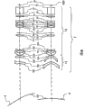
图16是用于说明本实施方式涉及的三维显示方法的原理的图。其中,图(a)是立体图,图(b)是大致从正面看时的图。FIG. 16 is a diagram for explaining the principle of the three-dimensional display method according to this embodiment. Among them, figure (a) is a perspective view, and figure (b) is a figure seen roughly from the front.
如图16所示,在视听影像的观看者250的前方,在纵深方向相异的位置设置多个显示面,例如设置第一显示面170a和第二显示面160a,使用后述的本实施方式的影像显示装置,在这些显示面上显示两个图像(二维图像)即第一图像175和第二图像155。其中,第一显示面170a与作为后述的第一光调制部的图像显示用液晶面板170的显示面(图像形成面)对应,第二显示面160a与通过投影透镜装置10对作为后述的第二光调制部的液晶面板150的显示面(图像形成面)进行放大投影后的投影图像面(成像面)对应。As shown in FIG. 16, in front of the viewer 250 who watches the video, a plurality of display surfaces are provided at different positions in the depth direction, for example, a
如专利文献1的图2所述那样,在第一显示面170a和第二显示面160a中显示的图像(二维图像)175、155为,从观看者的两眼的视线方向将希望呈现给观看者的三维物体(显示对象物)向上述显示面170a、160a投影的图像。As described in FIG. 2 of Patent Document 1, the images (two-dimensional images) 175 and 155 displayed on the
作为向这些显示面170a、160a投影的图像的形成方法,例如列举出,使用通过照相机从视线方向对三维物体进行拍照而获得的二维图像的方法、或对从其它方向拍照而获得的多张二维图像进行合成的方法、或使用基于计算机图片处理的合成技术、模型化的方法等各种方法。而且,在后述的本实施方式的影像显示装置中使用的第一影像信号、第二影像信号通过使用上述方法中的任一个生成,第一影像信号与第一图像对应,第二影像信号与第二图像对应,经常具有相异的信号成分。As a method of forming images projected onto these
另一方面,除了专利文献1所示的方法以外,本发明者们也确认到,通过在试制的影像显示装置中显示2种图像,通过改变第一图像和第二图像的大小、使亮度信号的电平相异,显示画面的内容即使相同,能够在视觉上也如同近似地进行三维显示。并且,通过增加第二图像的数目,能够得到更逼真的三维图像。On the other hand, in addition to the method shown in Patent Document 1, the present inventors have also confirmed that by displaying two types of images on a video display device manufactured as a trial, by changing the size of the first image and the second image, the luminance signal Even if the content of the display screen is the same, three-dimensional display can be performed visually as if the levels are different. Moreover, by increasing the number of second images, more realistic three-dimensional images can be obtained.
如图16(b)所示,分别在第一显示面170a和第二显示面160a这两个面上显示以上述方式生成的第一图像175和第二图像155,使得从连接观看者250的右眼和左眼的线上的一点观看时重合。在后述的本实施方式的影像显示装置中,因为能够使显示面的尺寸为27~100英寸(インチ)左右,并且能够以与画面尺寸匹配的方式使第一显示面170a与第二显示面160a之间的距离L为例如大致0mm~50mm左右的最佳显示距离,所以能够充分地满足上述条件。As shown in FIG. 16(b), the
然后,为了使得能够从两个图像(二维图像)感觉到三维图像(三维立体图像),将从观看者250看到的总体的亮度保持不变,同时使其按照三维物体距离观看者的纵深位置进行改变。Then, in order to make it possible to perceive a three-dimensional image (three-dimensional stereoscopic image) from two images (two-dimensional image), the overall brightness seen from the viewer 250 is kept constant while making it in accordance with the depth of the three-dimensional object from the viewer. The location is changed.
参照图16对该亮度的改变方法的一个例子进行说明。而且,在此,为了更容易理解,对亮度较高的图像较浓地进行表示。An example of how to change the brightness will be described with reference to FIG. 16 . In addition, here, for easier understanding, an image with high luminance is darkened.
即,例如,将从观看者250看到的总体的亮度保持不变,同时距离观看者越近的显示面(此处为第一显示面170a)越提高图像的亮度,距离观看者越远的显示面(此处为第二显示面155a)越降低图像的亮度。由此,观看者通过生理或心理的原因或者说错觉,即使显示的是二维图像,也感觉到在多个显示面(此处为第一显示面170a和第二显示面155a)之间存在三维图像。That is, for example, the overall brightness seen from the viewer 250 remains unchanged, and at the same time, the closer the display surface (here, the
通过使用以上所述的三维显示方法,通过在从观看者看纵深位置相异的多个显示面上分别形成多个图像(二维图像),能够显示三维图像(立体视图)。By using the three-dimensional display method described above, a three-dimensional image (stereoscopic view) can be displayed by forming a plurality of images (two-dimensional images) on a plurality of display surfaces at different depth positions as seen from the viewer.
接着,对本实施方式的影像显示装置进行说明。Next, the video display device of this embodiment will be described.
本实施方式的影像显示装置,为了在从观看者看纵深位置相异的多个显示面上分别形成多个图像(二维图像),具有至少两个用于形成作为图像的光学像的光调制部。而且,其特征在于,具有:用于按照第一影像信号光调制入射的光从而形成第一图像的第一光调制部;用于按照第二影像信号光调制来自光源的光的一个或多个第二光调制部;和配置在上述第一光调制部的光入射侧,对在上述第二光调制部光调制过的光进行放大投影从而在第一光调制部的光入射侧附近形成(投射)第二图像的放大像形成部,其中,上述第一光调制部,被射入通过上述放大像形成部形成的上述第二图像的光,并按照上述第一影像信号光调制该第二图像的光从而形成上述第一图像。在本实施方式中,如上所述,在放大像形成部对在第二光调制部形成的光学像(图像)进行放大投影(投射)形成第二图像。因此,因为能够使得第二光调制部的画面尺寸与第一光调制部的画面尺寸相比足够小,所以能够实现低成本的影像显示装置以及应用该装置的三维影像显示装置。另外,在以下的说明中,为了将在第二光调制部形成的光学像(图像)与放大投影后的第二图像区分出来,将其称为“原图像”或“第二原图像”。In order to form a plurality of images (two-dimensional images) on a plurality of display surfaces with different depth positions as seen from the viewer, the image display device of this embodiment has at least two optical modulators for forming an optical image as an image. department. Furthermore, it is characterized by comprising: a first light modulator for optically modulating incident light according to a first video signal to form a first image; one or more light modulators for lightly modulating light from a light source according to a second video signal the second light modulator; and disposed on the light incident side of the first light modulator, enlarged and projected the light modulated by the second light modulator so as to be formed near the light incident side of the first light modulator ( an enlarged image forming unit for projecting) a second image, wherein the first light modulation unit receives the light of the second image formed by the enlarged image forming unit, and modulates the second image according to the first image signal. The light of the image thus forms the above-mentioned first image. In this embodiment, as described above, the optical image (image) formed by the second light modulation unit is enlarged and projected (projected) by the enlarged image forming unit to form the second image. Therefore, since the screen size of the second light modulator can be made sufficiently smaller than that of the first light modulator, a low-cost video display device and a 3D video display device to which the device is applied can be realized. In addition, in the following description, in order to distinguish the optical image (image) formed by the second light modulator from the enlarged and projected second image, it is referred to as "original image" or "second original image".
图1是示意地表示本发明的一个实施方式的影像显示装置的结构图。在以下的实施例中,以使用透过型的液晶面板作为第二光调制部的情况为例进行说明。为了得到彩色图像,虽然需要与将白色光分离成RGB三原色的颜色分离单元分别对应的3块液晶面板以及将通过各液晶面板形成的各色光的图像合成为彩色图像的合成棱镜,但是在图1中,为了使说明简单而将它们省略,并且,对于各构成要素,没有顾及其实际的尺寸,只是示意地加以表示。FIG. 1 is a configuration diagram schematically showing a video display device according to an embodiment of the present invention. In the following embodiments, a case where a transmissive liquid crystal panel is used as the second light modulator is taken as an example for description. In order to obtain a color image, three liquid crystal panels corresponding to the color separation units that separate white light into the three primary colors of RGB and a synthesis prism that synthesizes the images of each color light formed by each liquid crystal panel into a color image are required, but in Fig. 1 In , these are omitted in order to simplify the description, and each component is shown schematically without considering its actual size.
在图1中,本实施方式的影像显示装置100构成为具有以下部件:作为用于形成第一图像的第一光调制部的图像显示用液晶面板170;形成第二图像的投影图像形成装置200;作为配置于图像显示用液晶面板170的入射侧附近的光方向变换部的菲涅尔透镜片(Fresnel lens sheet)160;驱动图像显示用液晶面板170使之形成第一图像的第一面板驱动电路192;和驱动投影图像形成装置200使之形成第二图像的第二面板驱动电路192。In FIG. 1 , an
另外,根据影像显示装置100的组装结构,也有可以使用光散射片代替菲涅尔透镜片160的情况。In addition, depending on the assembly structure of the
投影图像形成装置200从图像显示用液晶面板(也可以简称为“液晶面板”)170的背后对放大图像进行投影,在图像显示用液晶面板170的光入射侧附近形成第二图像,其中,该图像显示用液晶面板170作为按照第一影像信号193对光进行调制(光调制)的第一光调制部进行彩色显示。即,使用图16说明过的第二显示面160a位于图像显示用液晶面板170的光入射侧附近。而且,投影图像形成装置200朝向图像显示用液晶面板170,依次包括:射出大致白色光的光源110;作为将从光源110射出的没有起偏的光变换为所希望方向的偏振光成分并使其一致的偏振光变换部的偏振光变换元件130;作为对来自偏振光变换元件130的光(白色光)进行光调制而形成第二原图像的第二光调制部的液晶面板150;和作为放大像形成部的投影透镜装置10,其中,该投影透镜装置10将在液晶面板150对应于第二影像信号196而被光调制的光束(第二原图像)放大并朝作为第一光调制部的图像显示用液晶面板170投影,从而在图像显示用液晶面板170的光入射侧附近(例如,未图示的入射侧偏振光板附近)的第二显示面160a形成第二图像155。Projection
另外,在设置于图像显示用液晶面板170的光入射侧附近的第二显示面160a的显示面位置,以使得来自投影透镜装置10的光束几乎垂直地向图像显示用液晶面板170的入射面入射的方式,设置有作为进行变换的光方向变换部的菲涅尔透镜片160。因为通过该菲涅尔透镜片160使来自投影透镜装置10的光束为大致平行光束,所以仅向图像显示用面板入射对比度性能优异的角度成分的光,结果是能够大幅提高影像显示装置整体的对比度性能。另一方面,为了节约成本也能够省略菲涅尔透镜片160,但是在此情况下,因为必须追加光漫射效果较大的漫射片,所以不能得到上述效果,于是不能得到大幅提高对比度性能的效果。In addition, the display surface position of the
作为第一光调制部的图像显示用液晶面板170,通过第一面板驱动电路192根据第一影像信号193对从投影图像形成装置200照射的第二原图像被放大后的投影图像(第二图像155)的影像光再次进行光调制,形成作为主显示图像的第一图像175,然后射出。在此,采用用于横纵比为16∶9、像素数为1920×1080、画面尺寸(画面显示有效区域的对角尺寸L1)为27~60英寸左右的大画面直视型液晶TV中的有源矩阵驱动的TFT(Thin Film Transistor:薄膜晶体管)型液晶面板。一般而言,TFT型液晶面板的对比度为1000∶1左右。The
另外,设置在投影图像形成装置200中的作为第二光调制部的液晶面板150和作为第一光调制部的图像显示用液晶面板170,为了得到高对比度的影像,虽然在入射侧和出射侧具有偏振光板,但是省略其图示。并且,当不重视对比度性能时,因为省略任意一个偏振光板均能够得到所希望的性能,所以不一定需要所有的偏振光板。在此情况下,能够节约与省略的偏振光板的材料费用相同程度的成本。而且,因为在本发明的投影图像形成装置200设置有将从光源110射出的没有起偏的光变换为所希望方向的偏振光成分并使其一致的偏振光变换部,所以光的利用效率与通常的直视型液晶TV相比非常高。In addition, the
光源110例如包括:射出大致白色光的高亮度的高压水银灯等的灯101,和从背后覆盖灯101并反射来自灯101的白色光将其变换成平行光的旋转抛物面形状的反射镜(リフレクタ一)102。在本实施方式中,如后所述,因为从光源110射出的光照射到与图像显示用液晶面板170相比足够小且作为第二光调制部的液晶面板150上,所以能够使用高压水银灯等的放电灯。The
从灯101射出的光例如被具有旋转抛物面形状的反射面的反射镜102反射,变得与光轴115大致平行,于是,从光源110射出大致平行的光束。从光源110射出的光向偏振光变换元件130入射。The light emitted from the
偏振光变换元件130使从光源110射出的没有起偏的光与规定的偏振方向的偏振光一致。在偏振光变换元件130变换为规定偏振光的光向液晶面板150入射。The
作为第二光调制部的液晶面板150通过第二面板驱动电路195根据第二影像信号196进行光调制形成光学像(第二原图像)。在此,为了降低影像显示装置的价格,当不太重视析像度时,也有降低液晶面板150的析像度,使用更低价格的面板的情况。例如,在液晶面板170的横纵比为16∶9、HD的像素数为1920×1080的情况下,在成本优先的情况下也可以使用WSVGA的像素数852×480。另一方面,作为画面尺寸(画面显示有效区域的对角尺寸为L2),使用0.4~1.3英寸左右的单矩阵(single matrix)驱动的TN型液晶面板(透过型液晶面板)。The
一般而言,TN型液晶面板的对比度比为700∶1左右,比TFT型低。但是,在本发明中,因为对比度比为作为第二光调制部的液晶面板150的对比度比和作为第一光调制部的图像显示用液晶面板170的对比度比的乘积,所以虽然使用价格低廉的面板,但是具有能够显著提高对比度比的其他效果。Generally speaking, the contrast ratio of TN type liquid crystal panel is about 700:1, which is lower than that of TFT type. However, in the present invention, since the contrast ratio is the product of the contrast ratio of the
为了降低成本,当使作为第二光调制部的液晶面板150的析像度比作为第一光调制部的液晶面板170低时,第二面板驱动电路195形成为具有按比例缩放(scaling)功能(未图示)的结构,也存在对第二影像信号196按照液晶面板150的析像度进行按比例缩放等图像处理的情况。之后,驱动液晶面板150,形成第二原图像(光学像)。另外,也可以从第一液晶面板驱动电路192向液晶面板150供给用于供向图像显示用液晶面板170的RGB信号(根据需要,与液晶面板150的析像度对应地进行按比例缩放处理)。In order to reduce the cost, when the resolution of the
作为放大像形成部的投影透镜装置10构成为,将在液晶面板150形成的图像放大后向作为第一光调制部的图像显示用液晶面板170投影。这时,如果使用现有方式的投影透镜装置,则影像显示装置的纵深尺寸变大。因此,在本实施例中虽然在后面详细叙述,但是为了尽量使纵深尺寸较小,使用斜投影。
本发明的投影透镜装置10因为将液晶面板150的图像向着作为第一光调制部的图像显示用液晶面板170放大投影,所以必须满足以下条件。Since the
(数学式1)(mathematical formula 1)
10<L1/L2<15010<L1/L2<150
作为第二光调制部的液晶面板,其最小的型号现在为0.48英寸(对角尺寸)左右,认为0.4英寸是其极限。因此,如果令液晶面板150的图像尺寸为L2=0.4英寸且令图像显示用液晶面板170的画面尺寸为L1=60英寸,则L1/L2=150。如果L1/L2超过150,则会产生照射到作为第一光调制部的图像显示用液晶面板170的亮度变暗的问题。因此,优选令L1/L2为150以下。下限虽然与液晶面板150的画面尺寸相关,但是如果接近图像显示用液晶面板170的画面尺寸,则不能削减成本,所以优选至少令L1/L2=10以上。一般而言,如果令用于投影型影像显示装置的接近上限的画面尺寸L2=1.3英寸的面板为作为第二光调制部的液晶面板150,且令作为第一光调制部的图像显示用液晶面板170的画面尺寸为L1=27英寸,则L1/L2=20左右,能够满足上述条件。The smallest model of the liquid crystal panel serving as the second light modulator is about 0.48 inches (diagonal dimension) at present, and 0.4 inches is considered to be the limit. Therefore, if the image size of the
菲涅尔透镜片160设置在第二显示面160a的位置附近,为按照使来自投影透镜装置10的斜光大致垂直地向图像显示用液晶面板170的入射面入射的方式进行变换的光方向变换部。在构成菲涅尔透镜片160的基体材料161的一个面(此处为与图像显示用液晶面板170一侧相反的一侧的面)上,同心圆状地形成有多个折射型菲涅尔透镜162和全反射型菲涅尔透镜167,其中,折射型菲涅尔透镜162将入射角为规定值以内的光折射并射出,全反射型菲涅尔透镜167将入射角为规定值以上的光全反射并射出。于是,通过折射型菲涅尔透镜162和全反射型菲涅尔透镜167按照入射角度将来自投影透镜装置10的光折射或全反射,使得大致垂直地向图像显示用液晶面板170的入射面入射(后面详细叙述)。The
如上所述,在本实施方式中,使用尺寸小的液晶面板150,与第二影像信号对应地对光进行调制(光调制、光强度调制),通过投影透镜装置10将得到的图象(第二原图像)向作为第一光调制部的图像显示用液晶面板170放大投影,在图像显示用液晶面板170的光入射侧附近(例如入射侧偏振光板附近)形成第二图像155,并与第二影像信号对应地对射入上述液晶面板170的光束再次进行光调制(形成第一图像),由此,能够经由液晶面板170不是时间分割而是同时地显示从观看者看纵深位置相异的两个图像(第二图像和第一图像)。但是,利用本实施方式的影像显示装置100仅仅同时显示从观看者看的纵深位置相异的多个图像,立体感不充分。因此,应用在上述专利文献1公开的三维显示方法。即,例如,将从观看者250看到的总体的亮度保持不变,同时按照三维物体距离观看者的纵深位置改变亮度。作为具体的一个例子,例如,将从观看者250看到的总体的亮度保持不变,同时越靠近观看者的显示面(此处为第一显示面170a)越提高其图像的亮度,越远离观看者的显示面(此处为第二显示面155a)越降低其图像的亮度。As described above, in this embodiment, light is modulated (light modulation, light intensity modulation) corresponding to the second video signal using the small-sized
为了进行上述控制,当将影像显示装置100应用于三维影像显示装置300中时,三维影像显示装置300除了具有影像显示装置100之外,还具有控制电路310。In order to perform the above control, when the
控制电路310对于驱动作为第一光调制部的图像显示用液晶面板170的第一面板驱动电路192和驱动作为第二光调制部的液晶面板150的第二面板驱动电路195,以使得在第一图像和第二图像之间产生亮度差的方式进行控制。例如,对于第一面板驱动电路192以提高亮度的方式进行控制,而对于第二面板驱动电路195以降低亮度的方式进行控制。当然,也可以简单地仅对第二面板驱动电路195以降低亮度的方式进行控制。The
当然,控制电路不限于此。例如,如图17所示,三维影像显示装置300A也可以具有控制电路310A而代替控制电路310,向控制电路310A输入影像信号191,通过控制电路310A进行规定的信号处理,生成具有亮度差的第一影像信号(第一光调制部用)和第二影像信号(第二光调制部用),将生成的第一影像信号193’和第二影像信号196’分别供向第一面板驱动电路192、第二面板驱动电路195。Of course, the control circuit is not limited to this. For example, as shown in FIG. 17 , a 3D
而且,很明显,三维显示方法不限定于上述内容,也可以使用专利文献1公开的各种亮度控制方法。Also, it is obvious that the three-dimensional display method is not limited to the above, and various brightness control methods disclosed in Patent Document 1 may be used.
在此,对于本实施方式的影像显示装置100所具有的三维显示以外的其它特征,简单加以说明。Here, features other than the three-dimensional display included in the
在本实施方式的影像显示装置100中,如上所述,因为图像的对比度比为液晶面板150的对比度比和图像显示用液晶面板170的对比度比的乘积,所以能够显著地提高对比度比。In
另一方面,能够使用与作为第一光调制部的图像显示用液晶面板170相比足够小的作为第二光调制部的液晶面板150,而且,还能够使光源110的尺寸较小。因此,与使用与图像显示用液晶面板170为相同尺寸的昂贵的液晶面板的方式相比,虽然需要追加投影装置、菲涅尔透镜片,但是在能够使用低析像度的液晶面板的情况下,能够将影像显示装置的成本降低至2/3~1/2。On the other hand,
另外,通过将液晶面板150与合成棱镜(未图示)模块(block)化,成为使光源110能够分别交换的方式,能够大幅提高服务性。In addition, by making the
并且,与通常的直视型液晶影像显示装置不同,在图像显示用液晶面板170的附近,没有必要邻接设置作为发热源的光源(通常为冷阴极线管或LED),也能够容易地设计冷却结构。And, unlike common direct-view liquid crystal video display devices, there is no need to adjoin a light source (usually a cold-cathode tube or LED) as a heat source in the vicinity of the
以上虽然没有详细地叙述,即使使作为第二光调制部的液晶面板150的一个像素与作为第一光调制部的图像显示用液晶面板170的多个像素对应,或者相反,使液晶面板150的多个像素与图像显示用液晶面板170的一个像素对应,本发明也并不限定于此。当然,也可以使图像显示用液晶面板170的一个像素(一个像素包括一组R像素、G像素、1B像素)与液晶面板150的一个像素对应。Although not described in detail above, even if one pixel of the
另外,虽然使用高压水银灯作为光源,但是也可以使用白色光的LED、激光器。当一个LED、激光器的光量不够时,也可以使用排列有多个LED、激光器的装置。In addition, although a high-pressure mercury lamp is used as a light source, a white light LED or a laser may also be used. When the amount of light from one LED or laser is insufficient, a device in which a plurality of LEDs or lasers are arranged can also be used.
另外,作为与第二影像信号对应地对来自光源的光束进行光调制的第二光调制部,虽然使用透过型的液晶面板,但是也可以代替该透过型的液晶面板,使用反射型光调制元件,例如,反射型液晶面板(LCOS:Liquid Crystal on Silicon)、微小镜元件(DMD:Digital MicroMirror Device)等。In addition, although a transmissive liquid crystal panel is used as the second light modulator for optically modulating the light beam from the light source in accordance with the second video signal, a reflective light may be used instead of the transmissive liquid crystal panel. Modulation elements, for example, reflective liquid crystal panel (LCOS: Liquid Crystal on Silicon), micro mirror element (DMD: Digital MicroMirror Device), etc.
接着,对投影透镜装置的一个实施例进行说明。此处,为了使影像显示装置的纵深尺寸尽量薄,应用发明者申请的日本专利特开2006-292900号公报中记载的投影透镜装置。Next, an example of the projection lens device will be described. Here, in order to make the image display device as thin as possible in depth, the projection lens device described in Japanese Patent Application Laid-Open No. 2006-292900 filed by the inventor is applied.
图2是表示影像显示装置中的投影透镜装置的基本光学系统的结构的截面图,以XYZ正交坐标系中的YZ截面表示光学系统的结构。此处,令XYZ正交坐标系的原点为液晶面板150的显示画面的中央,令Z轴与图像显示用液晶面板170的法线8平行。令Y轴与图像显示用液晶面板170的显示画面的短边平行,且与图像显示用液晶面板170的纵(上下)方向相等。令X轴与图像显示用液晶面板170的显示画面的长边平行,且与图像显示用液晶面板170的横(左右)方向相等。另外,图3是构成投影图像形成装置的投影透镜装置的立体图,图4是省略投影透镜装置中的光路的折曲而表示的投影透镜的截面图。其中,在图2中,为了使图示简单,省略作为光方向变换部的菲涅尔透镜片160。2 is a cross-sectional view showing the configuration of a basic optical system of a projection lens device in an image display device, and the configuration of the optical system is shown by a YZ cross section in an XYZ rectangular coordinate system. Here, the origin of the XYZ rectangular coordinate system is set to be the center of the display screen of
如图2所示,投影透镜装置10包括:在从液晶面板150朝向菲涅尔透镜片160、图像显示用液晶面板170的光路上从液晶面板150一侧起依次配置的投影透镜2、作为第一反射镜的自由曲面镜4、和作为第二反射镜的平面反射镜5。As shown in FIG. 2 , the
液晶面板150的显示画面上的第二原图像被投影透镜2向作为第一光调制部的图像显示用液晶面板170投影。这时,如果进行直线投影则需要规定的距离,影像显示装置100的纵深尺寸变长。即,影像显示装置100的纵深变厚。于是,以自由曲面镜4和平面反射镜5折回从投影透镜2朝向图像显示用液晶面板170的光路(例如,光线21、22、23表示的光路),从而使得影像显示装置100的纵深较小。而且,令从液晶面板150的画面的中央射出并朝向图像显示用液晶面板170的画面中央的光线21(以下,称为“画面中央光线”)相对于图像显示用液晶面板170的入射面非垂直(一般而言,称这样的投影为“斜投影”),使影像显示装置100的纵深较小。The second original image on the display screen of the
从图2、图4明显可知,投影透镜2由前组12和后组13构成,其中,前组12由具有旋转对称的面形状的多个折射透镜构成,后组13包括至少一个面具有旋转非对称的自由曲面的形状的透镜(以下,称为“自由曲面透镜”)。It can be clearly seen from Fig. 2 and Fig. 4 that the
在图2中,因为投影透镜2的长度较长,所以可能看起来液晶面板150的位置相对于图像显示用液晶面板170的法线8的方向较远,纵深变得较厚。但是,此处,如图3所示,在与X轴(即,图像显示用液晶面板的长边)平行配置的前组12的途中配置有光路折弯镜14,将前组12的光轴9(即投影透镜的光轴)向Z轴方向(即,与图像显示用液晶面板170的法线8平行的方向)折弯,防止纵深的增大。当然,本发明不限于此,也可以在自由曲面镜4与投影透镜2的后组13之间、或投影透镜2的前组12与后组13之间配置折弯光路的光路折弯镜。In FIG. 2 , since the length of the
在本实施方式中,如图2所示,液晶面板150的显示画面的中央配置在投影透镜2的光轴9上。因此,从液晶面板150的显示画面的中央射出通过投影透镜2的入射光瞳的中央后朝向图像显示用液晶面板170的画面中央的画面中央光线21沿投影透镜的光轴前进。该画面中央光线21在自由曲面镜4的反射面上的点P2被反射后,在平面反射镜5上的点P5被反射,相对于图像显示用液晶面板的入射面的法线8按照规定的角度(θs)(即倾斜)入射到图像显示用液晶面板170的画面中央的点P8。In this embodiment, as shown in FIG. 2 , the center of the display screen of
该状态为沿投影透镜2的光轴9通过的光线相对于图像显示用液晶面板170倾斜入射的状态,实质上被设定为投影透镜2的光轴相对于图像显示用液晶面板170倾斜。如果以这样的方法向图像显示用液晶面板170倾斜入射,则除了投影的长方形的形状成为梯形的所谓梯形畸变以外,还会产生相对于光轴不旋转对称的各种像差。于是,在本实施方式中,通过投影透镜2的后组13和自由曲面镜4的反射面对以上情况进行修正。This state is a state in which light rays passing along the optical axis 9 of the
在图2所示的截面内,令从液晶面板150的画面下端通过投影透镜2的入射光瞳的中央后射出且入射到与此对应的图像显示用液晶面板170的画面上端的点P9的光线为光线22。并且,令从液晶面板150的画面上端通过投影透镜2的入射光瞳的中央后射出且入射到与此对应的图像显示用液晶面板170的画面下端的点P7的光线为光线23。观察图2可知,从点P3经由点P6到达点P9的光路长比从点P1经由点P4到达点P7的光路长更长。这意味着,从投影透镜2看,图像显示用液晶面板170的像点P9位于比像点P7更远的位置。因此,如果与图像显示用液晶面板170的像点P9对应的物点(液晶面板150的显示画面上的点)比距离投影透镜2较近的点,或与像点P7对应的物点为距离投影透镜2较远的点,就能够修正像面的倾斜。为此,令液晶面板150的显示画面的中央的法线矢量相对于投影透镜2的光轴倾斜。具体而言,使上述法线矢量在YZ平面内以朝向图像显示用液晶面板170的所处位置的方式倾斜即可。已知为了得到相对于光轴倾斜的像平面而倾斜物平面的方法。但是,如果利用实用大小的视角,则基于物平面的倾斜的像面相对于光轴产生非对称的变形,因此利用旋转对称的投影透镜难以进行修正。于是,在本实施方式中,使用非旋转对称即旋转非对称的自由曲面,对应非对称的像面的变形。因此,通过倾斜物平面能够大幅降低低程度的像面的畸变,在辅助基于自由曲面的像差修正方面有效果。In the cross-section shown in FIG. 2 , let the light from the lower end of the screen of the
接着,对各光学要素的作用进行说明。投影透镜2中的前组12为用于将作为第二光调制部的液晶面板150的第二原图像(通过光调制得到的二维图像)放大投影到作为第一光调制部的图像显示用液晶面板170(正确而言,使之在图像显示用液晶面板170的入射侧附近例如未图示的入射侧偏振光板附近成像)的主透镜,修正旋转对称的光学系统中的基本的像差。投影透镜2的后组13包括旋转非对称的自由曲面透镜。此处,从图2、图3、图4明显可知,自由曲面透镜以相对于其光射出方向凹下的方式弯曲。并且,使自由曲面透镜的朝向图像显示用液晶面板170的下端的光线23透过的部分的曲率比朝向图像显示用液晶面板170的上端的光线22透过的部分的曲率大。Next, the action of each optical element will be described. The
自由曲面镜4具有旋转非对称的自由曲面形状的反射面。此处,令自由曲面镜4为其一部分以相对于光的反射方向凸起的方式弯曲的旋转非对称的凸面镜。具体而言,令自由曲面镜4的反射朝向图像显示用液晶面板170的下方的光的部分(P1)的曲率比反射朝向图像显示用液晶面板170的上方的光的部分(P3)的曲率大。换言之,在自由曲面镜4的YZ截面(图像显示用液晶面板170的画面纵方向截面)中,对于画面中央光线21被自由曲面镜4反射的位置P2,使P1-P2之间的尺寸与P3-P2之间的尺寸相异,从而使得以下数学式成立。The free-
(数学式2)(mathematical formula 2)
P1-P2之间的尺寸<P3-P2之间的尺寸The size between P1-P2 < the size between P3-P2
另外,也可以使得,自由曲面镜4的反射朝向图像显示用液晶面板170的下方的光的部分(P1)为向该光的反射方向凸出的形状,反射朝向图像显示用液晶面板170的上方的光的部分(P3)为向光的反射方向凹下的形状。In addition, the part (P1) of the free-
通过上述自由曲面透镜和自由曲面镜的作用,主要对因倾斜入射产生的像差进行修正。即,在本实施方式中,自由曲面镜4主要修正梯形畸变,投影透镜2的后组13主要进行像面的畸变等非对称的像差的修正。Through the functions of the above-mentioned free-form surface lens and free-form surface mirror, the aberration caused by oblique incidence is mainly corrected. That is, in this embodiment, the free-
这样,本实施方式中,投影透镜2至少包括一个旋转非对称的自由曲面透镜,自由曲面镜4为旋转非对称的自由曲面形状的反射镜。因此,能够同时修正因斜投影产生的梯形畸变和像差。结果是,根据第二影像信号将通过液晶面板150光调制过的第二原图像放大,向图像显示用液晶面板投影,并且将该影像光束作为近似的二次光源,通过图像显示用液晶面板根据第一影像信号再次进行光调制。从观看侧能够不是时间分割而是同时地观察纵深位置相异的两个图像即第二图像155和第一图像175。Thus, in this embodiment, the
进一步,作为这两个图像(第二图像和第一图像),使用从观看者的视线方向对显示对象物进行投影后的二维图像,通过作为第二光调制部的液晶面板150的放大像(投影图像)生成从其中的观看侧看的里侧的二维图像,通过作为上述第一光调制部的图像显示用液晶面板170显示从另一方的观看侧看的跟前侧的二维图像,由此,能够实现能够显示三维图像的三维影像显示装置(例如,参照图16)。这时,当然,为了增加图像的纵深方向的信息量从而提高三维图像的精细度,增加作为上述第二图像的投影图像(二维图像)的显示图像数即可。Furthermore, as these two images (the second image and the first image), a two-dimensional image obtained by projecting a display target object from the viewer's line of sight is used, and an enlarged image of the
接着,使用图5、图6和表1~表4,例示具体的数值,同时对以上所述的投影透镜装置10的光学系统进行说明。Next, the optical system of the above-mentioned
图5和图6表示基于数值例的本实施方式涉及的投影透镜装置的光学系统的光线图。在上述的XYZ正交坐标中,图5表示YZ截面的结构,图6表示XZ截面的结构。投影透镜2,如图3所述,在前组12的途中配置有光路折弯镜14,但是在图5中,省略该光路折弯镜14,将光学系统在Z轴方向展开加以表示。该情况在图4中也相同。光路折弯镜在设置的位置、角度上有若干的任意性,并且不会影响各光学要素的功能。因此,在以下的说明中,省略光路折弯镜进行说明。5 and 6 show ray diagrams of the optical system of the projection lens device according to the present embodiment based on numerical examples. In the above-mentioned XYZ orthogonal coordinates, FIG. 5 shows the structure of the YZ cross section, and FIG. 6 shows the structure of the XZ cross section. The
从表示于图5的下侧的液晶面板150射出的光,首先通过包括多个透镜的投影透镜2中的、仅由只具有旋转对称形状的面的透镜构成的前组12。然后,通过包括旋转非对称的自由曲面透镜的后组13,在自由曲面镜4的反射面被反射。该反射光在平面反射镜5被反射后,入射到图像显示用液晶面板170。Light emitted from
此处,投影透镜2的前组12全部由具有旋转对称的形状的折射面的多个透镜构成,各折射面中的四个为旋转对称的非球面,其它为球面。此处使用的旋转对称的非球面,使用每个面的局部的圆柱坐标系,用以下数学式表示。Here, the
(数学式3)(mathematical formula 3)
此处,r是距离光轴的距离,Z表示下垂(sag)量。并且,c是在顶点的曲率,k是圆锥常数,A~J是r的幂乘的项的系数。Here, r is the distance from the optical axis, and Z represents the amount of sag. In addition, c is the curvature at the vertex, k is the conic constant, and A to J are coefficients of terms multiplied by powers of r.
投影透镜2的后组13中的自由曲面透镜使用以各面的面顶点为原点的局部的正交坐标系(x、y、z),以包括X、Y的多项式的以下的数学式表示。The free-form surface lenses in the
(数学式4)(mathematical formula 4)
此处,Z表示在与X、Y轴垂直的方向自由曲面的形状的下垂量,c是在顶点的曲率,r是在X、Y轴的平面内的距离原点的距离,k是圆锥常数,C(m、n)是多项式的系数。Here, Z represents the sagging amount of the shape of the freeform surface in the direction perpendicular to the X, Y axes, c is the curvature at the vertex, r is the distance from the origin in the plane of the X, Y axes, k is the conic constant, C(m, n) is a coefficient of a polynomial.
表1表示本实施方式涉及的光学系统的数值数据。在表1中,S0~S23与图4所示的符号S0~S23分别对应。此处,S0表示液晶面板150的显示面、即物面,S23表示自由曲面镜4的反射面。另外,S24虽然在图4中没有表示,但是表示图像显示用液晶面板170的入射面、即像面。其中,在图4中,上图表示本实施方式涉及的投影透镜2和自由曲面镜4的YZ截面图,下图表示该光学系统的XZ截面图。Table 1 shows numerical data of the optical system according to this embodiment. In Table 1, S0 to S23 correspond to symbols S0 to S23 shown in FIG. 4 , respectively. Here, S0 represents the display surface of
在表1中,Rd是各面的曲率半径,在图5中,当曲率的中心位于面的左侧时以正值表示,在相反的情况下以负值表示。并且,在表1中,TH是面间距离,表示从其透镜面的顶点到下一透镜面的顶点的距离。当相对于某一透镜面其后续的透镜面在图5中位于左侧时面间距离以正值表示,当位于右侧时以负值表示。而且,在表1中,S5、S6、S17、S18是旋转对称的非球面,在表1中在面号码的旁边注上*便于理解地表示。表2表示这四个面的非球面的系数。In Table 1, Rd is the radius of curvature of each surface, and in FIG. 5, when the center of curvature is located on the left side of the surface, it is represented by a positive value, and in the opposite case, it is represented by a negative value. In addition, in Table 1, TH is an interplanetary distance, and represents the distance from the apex of the lens surface to the apex of the next lens surface. The inter-surface distance is represented by a positive value when the subsequent lens surface is located on the left side of a certain lens surface in FIG. 5 , and is represented by a negative value when located on the right side. In addition, in Table 1, S5, S6, S17, and S18 are rotationally symmetric aspherical surfaces, and in Table 1, * is added next to the surface number for easy understanding. Table 2 shows the coefficients of the aspheric surfaces of these four surfaces.
在表1中,S19~S22是投影透镜2的后组13所包括的自由曲面透镜的各个折射面,如上所述,S23是自由曲面境4的反射面,在面号码的旁边注上#表示。将表示这五个自由曲面的形状的系数的值表示于表3中。In Table 1, S19 to S22 are the respective refraction surfaces of the free-form surface lenses included in the
在本实施方式中,使作为影像显示元件11的显示画面的物面相对于投影透镜2的光轴倾斜-1.163度。倾斜的方向为,令在图5的截面内物面的法线逆时针旋转的方向以正值表示。因此,在本实施例内在图5的截面内使物面从垂直于投影透镜2的光轴的位置向顺时针方向倾斜1.163度。In this embodiment, the object plane serving as the display screen of the video display element 11 is inclined by −1.163 degrees with respect to the optical axis of the
S23的自由曲面镜4将局部坐标的原点设置在投影透镜2的光轴上。并且,令在自由曲面镜4的局部坐标的原点的法线、即Z轴从与投影透镜2的光轴平行的位置倾斜29度而加以配置。与上述物面同样地令在图5的截面内逆时针旋转的方向为正,因此倾斜的方向逆时针倾斜。由此,从液晶面板150的画面中央射出并大致沿投影透镜2的光轴前进的画面中央光线,在S23反射后,向相对于投影透镜2的光轴只倾斜上述倾斜角度的2倍的58度的方向前进。在此,令通过S23的坐标原点且相对于投影透镜2的光轴的S23的倾斜角度的2倍的倾斜方向为反射后的新光轴,令以后的面为配置在该光轴上的面。表1的S23所示的面间隔的值-400表示,后续的S24表示位于S23的右侧,且将局部坐标的原点配置在沿上述反射后的光轴400mm的距离的点。以下的面也根据同样的规则配置。The free-
表4表示本实施例中的各面的局部坐标系的倾斜或偏心的情况。在表4中,在面号码的右侧表示倾斜角度、偏心的值。ADE是在与图5的截面平行的面内的倾斜的大小,其显示规则如以上所说明的那样。另外,YDE是偏心的大小,偏心被设定在与图5的截面平行的面内且与光轴垂直的方向,在图5的截面内令向下侧的偏心为正。并且,在本实施例中,令YDE为0(即没有偏心)。Table 4 shows the inclination or eccentricity of the local coordinate system of each surface in this embodiment. In Table 4, the values of inclination angle and eccentricity are shown on the right side of the surface number. ADE is the magnitude of the inclination in a plane parallel to the cross section of FIG. 5 , and the display rules are as described above. In addition, YDE is the magnitude of eccentricity, and eccentricity is set in a direction perpendicular to the optical axis in a plane parallel to the cross section of FIG. 5 . In the cross section of FIG. 5 , downward eccentricity is defined as positive. And, in this embodiment, let YDE be 0 (ie no eccentricity).
在本实施方式中,所有的光学要素的倾斜、偏心均被设定在与图示的截面平行的截面内的方向。In this embodiment, the inclination and decentering of all the optical elements are set in directions within a cross section parallel to the illustrated cross section.
根据表1、表3可知,在本实施例中,曲率c和锥形系数(コ一ニツク係数)k为0。基于斜入射的梯形畸变在斜入射的方向上极端地发生,而与此垂直的方向上的畸变量较小。因此,在斜入射的方向和与之垂直的方向上,需要有很大不同的功能,通过不使用旋转对称且在全方向上发挥作用的上述曲率c、锥形系数k,能够良好地修正非对称的像差。According to Table 1 and Table 3, it can be seen that in this embodiment, the curvature c and the conical coefficient (conic coefficient) k are 0. Keystone distortion based on oblique incidence occurs extremely in the direction of oblique incidence, and the amount of distortion in the direction perpendicular thereto is small. Therefore, functions that are very different are required in the direction of oblique incidence and in the direction perpendicular to it. By using the above-mentioned curvature c and taper coefficient k that function in all directions without rotational symmetry, abnormalities can be corrected well. Symmetrical aberrations.
(表1)(Table 1)
(表2)(Table 2)

(表3)(table 3)

(表4)(Table 4)
上述表1~4的数值是将液晶面板150的画面上的16×9的范围的被光调制后的光学像(调光像)投影为图像显示用液晶面板170的画面上的1452.8×817.2的大小的情况的一个例子。图7表示这时的图形畸变。图7的纵方向为图5的上下方向,是Y轴的方向。图7的横方向在图像显示用液晶面板170上是与Y轴正交的方向,图中的长方形的中央是画面的中央。该图表示将画面的纵方向分成4部分、将横方向分成8部分的直线的弯曲的状态并表示图形畸变的情况。The above-mentioned numerical values in Tables 1 to 4 are obtained by projecting the light-modulated optical image (dimming image) in the range of 16×9 on the screen of the
图8表示本数值实施例的光点图。在图8中,在液晶面板150的显示画面上,从上部依次显示从X、Y坐标的值为(8、4.5)、(0、4.5)、(4.8、2.7)、(8、0)、(0、0)、(4.8、-2.7)、(8、-4.5)、(0、-4.5)的8点射出的光束的光点图。单位为mm。各光点图的横方向是在图像显示用液晶面板170上的X方向,纵方向是在图像显示用液晶面板170上的Y方向。这样,两方面均能够维持良好的性能。以上,对投影透镜装置的一个实施例进行了说明。而且,在上述中,虽然以下述方式构成,即从投影透镜2射出的光线在自由曲面镜4被反射,进一步在平面反射镜5被折回,然后朝向图像显示用液晶面板170,但本发明不限于此,根据投影透镜的配置位置,当然也可以省略上述折回用的平面反射镜。Fig. 8 shows a spot diagram of the present numerical example. In FIG. 8, on the display screen of the
接着,对作为光方向变换部的菲涅尔透镜片160的一个实施例进行说明。Next, an example of the
图9是菲涅尔透镜片的示意构成图,其(a)图是从投影装置侧看菲涅尔透镜片时的立体结构图,其(b)图是沿G-G线的截面结构图。Fig. 9 is a schematic structural diagram of a Fresnel lens sheet, its (a) figure is a three-dimensional structural view when viewing the Fresnel lens sheet from the projection device side, and its (b) figure is a cross-sectional structural view along the G-G line.
如图9所示,菲涅尔透镜片160由处于与图像显示用液晶面板170的画面大致中央侧对应的位置的折射区域160D、和处于与图像显示用液晶面板170的画面的周边侧对应的位置且以包围折射区域160D的方式配置的全反射区域160E构成。在折射区域160D在基体材料161的与图像显示用液晶面板170相反一侧的面上同心圆状地形成有多个折射型菲涅尔透镜162。折射型菲涅尔透镜162具有将从投影透镜装置10投影的入射角为规定值以内的光线L61折射并使之向图像显示用液晶面板170垂直地射出的功能。另外,在全反射区域160E在基体材料161的与图像显示用液晶面板170相反一侧的面上同心圆状地形成有多个全反射型菲涅尔透镜167。全反射型菲涅尔透镜167具有将从投影装置10投影的入射角为规定值以上的光线L66全反射并使之向图像显示用液晶面板170垂直地射出的功能。As shown in FIG. 9 , the
众所周知,如果仅以折射型菲涅尔透镜构成菲涅尔透镜片(フレネルレンズシ一ト),则随着向菲涅尔透镜片入射的入射角(与法线所成的角度)变大,容易在菲涅尔透镜的入射面产生反射,因反射损失大幅增加而导致画面的周边部变暗。因此,在本实施例中,适用WO2004/049059号公报的技术,在第一图像显示用液晶面板170的周边部,在来自投影装置10的入射角为规定值以上的区域,配置全反射型棱镜。As everyone knows, if the Fresnel lens sheet (Frenel Lens set) is composed of only the refracting Fresnel lens, then as the incident angle (the angle with the normal) to the Fresnel lens sheet becomes larger, Reflection is likely to occur on the incident surface of the Fresnel lens, and the peripheral part of the screen becomes dark due to a large increase in reflection loss. Therefore, in the present embodiment, the technique of WO2004/049059 is applied, and a total reflection prism is arranged in a region where the incident angle from the
首先,对折射区域160D中的折射型菲涅尔透镜162进行说明。First, the
如果将菲涅尔透镜片160的折射区域160D中的任意的截面中的各折射型菲涅尔透镜的棱镜面163连在一起,则得到一个曲线(即,包络线)。得到的包络线的所有截面中的集合形成一个假想面。以下,称该假想面为“原面”。If the prism surfaces 163 of the respective refractive Fresnel lenses in any cross section in the
附随构成折射区域160D的折射型菲涅尔透镜的原面在投影型影像显示装置中,一般为球面,但是在本实施方式中,应用日本专利特开2006-154719号公报所公开的菲涅尔透镜片的技术,为与从投影装置10向图像显示液晶面板170入射的光线的入射角对应的非球面形状。The original surface of the refraction-type Fresnel lens accompanying the
这时,各棱镜面的菲涅尔角在折射区域160D中,上部比下部大。由此,入射到菲涅尔透镜片160的折射区域160D的入射面的光线被变换为,漫及图像显示用液晶面板170的大致整个面上,几乎垂直地向图像显示用液晶面板170的入射面入射。At this time, the Fresnel angle of each prism surface is larger in the upper part than in the lower part in the
接着,参照图10的示意图,对在形成于上述折射区域160D的折射型菲涅尔透镜162中,设定同心圆状地形成的多个棱镜面163的面形状(所谓的菲涅尔透镜的原面)的方法进行详细说明。而且,如上所述,构成折射区域160D的折射型菲涅尔透镜的棱镜面形成为以某一点(旋转轴)为中心的同心圆状。并且,用于决定各折射型菲涅尔透镜的棱镜面的菲涅尔角(即,棱镜面与菲涅尔透镜片160的主平面所成的角度)的原面为非球面形状。此处,如上所述,所谓原面是用于决定各棱镜面的菲涅尔角的面,指当令菲涅尔透镜片160的折射区域160D整体为一个透镜时的该透镜面。即,当设定折射型菲涅尔透镜的棱镜面的菲涅尔角时,首先假定菲涅尔透镜片160的折射区域160D整体具有某一个透镜特性,将该透镜的面形状设定为原面。然后,在折射区域160D的面上展开与该原面的折射区域160D各点对应的形状(例如,该各点的原面的切线)。由此,折射区域160D的各点的棱镜面的菲涅尔角被设定。因此,按照该菲涅尔角将菲涅尔透镜片的折射区域160D整体的各棱镜面连在一起的曲线,即包括菲涅尔透镜片的折射区域160D整体的所有棱镜面的集合的包络线,表示上述原面。即,折射区域160D的各点的棱镜面的光的折射方向由与各个棱镜对应的上述原面的形状决定。其中,令上述旋转轴与菲涅尔透镜片160的主平面(图10的XY面)正交(包含图的Z轴的面)。并且,该旋转轴包含向菲涅尔透镜片160入射的光线25与将菲涅尔透镜片160左右相等地垂直分割的面165(与YZ面平行的面)相交的点P15。即,旋转轴为与菲涅尔透镜片160的主平面垂直(与第一图像显示用液晶面板170的法线8平行)的轴、即图10的轴166。Next, with reference to the schematic diagram of FIG. 10 , in the refracting
但是,在上述中,因为入射的光线25根据图像显示用液晶面板170上的位置其入射角度(相对于入射面的法线的角度)而变化,所以在此,通过上述方法求得的轴166存在多个。并且,从这多个轴中,令位于其大致中央的轴为折射型菲涅尔透镜的旋转轴(即,构成折射型菲涅尔透镜的同心圆状棱镜的中心位置)。However, in the above, since the
接着,以下述方式求取上述各棱镜面的菲涅尔角的形状(角度)。首先,在折射区域160D的棱镜面使入射向图像显示用液晶面板170的入射光线折射,同时对于折射区域160D各点,分别根据菲涅耳定律求取用于使之向上述法线方向(出射角为0度)射出的棱镜的角度。接着,使该求得的棱镜面连续,形成上述折射型菲涅尔透镜的原面(非球面)。Next, the shape (angle) of the Fresnel angle of each of the above-mentioned prism surfaces is obtained as follows. First, on the prism surface of the
其中,该求取的原面由数学式3的非球面式近似求得。Wherein, the original surface to be obtained is approximated by the aspheric surface expression of
(数学式5)(mathematical formula 5)
此处,Z是与Z轴平行的面的下垂量,r是距离旋转轴的距离,c是在顶点的曲率,k是锥形常数(圆锥常数),A~F是r的乘幂项的系数(非球面系数)。Here, Z is the amount of sagging of the surface parallel to the Z axis, r is the distance from the rotation axis, c is the curvature at the vertex, k is the cone constant (conic constant), and A to F are the power terms of r. coefficient (aspherical coefficient).
这时,进一步进行近似的非球面系数与实际的光线射出角的比较,以使得射出角成为接近0度的方式对旋转轴的位置、非球面系数施加适当且必要的修正和/或变更。At this time, the approximate aspheric coefficient is further compared with the actual ray exit angle, and the position of the rotation axis and the aspheric coefficient are appropriately and necessary corrected and/or changed so that the exit angle becomes close to 0 degrees.
如上所述,通过上述求取的要素,即成为构成折射型菲涅尔透镜的同心圆状的棱镜部的旋转中心的旋转轴的位置、由该各个棱镜面的集合形成的原面的非球面系数,构成上述菲涅尔透镜片160的折射区域160D部分。As described above, the elements determined above, that is, the position of the rotation axis that becomes the rotation center of the concentric prism portion constituting the refracting Fresnel lens, and the aspheric surface of the original surface formed by the collection of the respective prism surfaces The coefficient constitutes the portion of the
图11表示经过上述过程而构成的菲涅尔透镜片160的示意截面图。图11表示菲涅尔透镜片160的与该菲涅尔透镜片160的法线平行且包含上述旋转轴的截面。FIG. 11 shows a schematic cross-sectional view of the
在图11中,Z=f(r)是表示附随菲涅尔透镜片160的折射区域160D中的折射型菲涅尔透镜的非球面形状的原面164的多项式,以数学式5表示。r与上述数学式5的r对应,表示距离旋转轴的距离。距离r1的折射型菲涅尔透镜的棱镜面163的菲涅尔角θ1(菲涅尔透镜片160的主平面与棱镜面成的角度)与距离r1的原面164的倾斜(切线)大致相等。即,当令以数学式3表示的原面的非球面式为Z=f(rn)且n为1以上的整数时,折射区域160D的各位置的菲涅尔角θn由数学式6表示。In FIG. 11 , Z=f(r) is a polynomial representing the aspherical
(数学式6)(mathematical formula 6)
θn=f(rn)’θn=f(rn)'
由此,θ1=f(r 1)’,θ2=f(r2)’,θ3=f(r3)’……。这样,折射区域160D的各位置的菲涅尔角θn与非球面式的各位置(各距离rn)的微分值大致对应。这样,菲涅尔透镜片160中的折射区域160D的各位置的菲涅尔角θn被设定。Thus, θ1=f(r 1)’, θ2=f(r2)’, θ3=f(r3)’……. In this way, the Fresnel angle θn at each position of the
如上所述,从投影透镜装置10向菲涅尔透镜片160的折射区域160D入射的光线被折射型菲涅尔透镜的各棱镜面163折射。如上所述,如果令折射型菲涅尔透镜的原面164为与向折射区域160D各位置入射的入射光线的入射角对应的非球面形状,则被各棱镜面163折射的各光线与菲涅尔透镜片160的法线大致平行。此处,从图11明显可知,位于菲涅尔透镜片160的折射区域160D上部的(即,在图像显示用液晶面板的纵方向上部远离旋转轴的位置的)棱镜面163的菲涅尔角θ,比位于菲涅尔透镜片160的折射区域160D下部的(即,在图像显示用液晶面板的纵方向下部接近旋转轴的位置的)棱镜面163的菲涅尔角θ大。这是因为,在本实施方式中的斜投影中,图像显示用液晶面板上部与图像显示用液晶面板下部相比其光线的入射角较大。As described above, light incident on the
接着,参照图11,对全反射区域160E中的全反射型菲涅尔透镜167进行说明。Next, the total
如图11所示,全反射区域160E的全反射型菲涅尔透镜包括折射面1671和全反射面1672。入射到位于全反射区域160E的全反射型菲涅尔透镜167的光线L66在其折射面1671被折射,然后朝向全反射面1672。然后,在全反射面1672被全反射,从菲涅尔透镜片160射出,垂直地向图像显示用液晶面板170入射。As shown in FIG. 11 , the total reflection Fresnel lens in the
为了使入射光线向图像显示用液晶面板170垂直地射出,对全反射面1672与主平面所成的角α进行设定,使得从与投影装置10较近的全反射型菲涅尔透镜到较远的全反射型菲涅尔透镜逐渐变小,或者,也可以对折射面1671与主平面所成的角β进行设定,相反地使得从与投影装置10较近的全反射型菲涅尔透镜到较远的全反射型菲涅尔透镜逐渐变大。这样,能够使入射到全反射区域的光线向图像显示用液晶面板170垂直地射出。In order for the incident light to exit perpendicularly to the
如果如上述那样构成菲涅尔透镜片160,则能够将从投影透镜装置10向图像显示用液晶面板170投影的光线加以变换并使之射出,使得其向图像显示用液晶面板170入射的入射角大致为0度。因此,如果使用本实施方式的菲涅尔透镜片,则来自投影透镜装置10的光线能够与图像显示用液晶面板170的法线平行地(即,与图像显示用液晶面板170垂直)入射,所以能够在图像显示用液晶面板170上显示高对比度的图像。If the
另外,在上述菲涅尔透镜片160中,在片的入射侧设置有折射区域和全反射区域,但本发明不限于此。例如,如本发明者所申请的日本专利特开2005-91541号公报所示那样,也可以在片的入射侧在入射角为规定以上的周边部设置全反射区域,而在片的射出侧在入射角为规定以下的中央部设置折射区域。In addition, in the
(实施例1)(Example 1)
在图1所示的影像显示装置中,因为从光源110向液晶面板照射的光量分布(也称为光强度分布,照度分布)不一样(不均匀),所以在图像显示用液晶面板上的图像中在明亮度上存在发生不均匀的问题。于是,使用图12,对在光源与液晶面板之间插入有用于使来自光源的照明光的光量分布均匀的联合组件(integrater)的实施例1的投影图像形成装置进行说明。In the image display device shown in FIG. 1, since the distribution of light intensity (also called light intensity distribution, illuminance distribution) irradiated from the
图12是实施例1的投影图像形成装置的示意结构图。FIG. 12 is a schematic configuration diagram of the projection image forming apparatus of Embodiment 1. FIG.
如图12所示,本实施例的投影图像形成装置包括:光源110、成对并作为多透镜方式联合组件120发挥作用的第一多透镜元件121以及第二多透镜元件122、偏振光变换元件130A、重叠透镜141、场透镜145、第二液晶面板150、和投影透镜装置10。As shown in FIG. 12, the projection image forming apparatus of this embodiment includes: a
光源110由灯101和反射镜102构成。灯101是高压水银灯的白色灯。反射镜102以从背后侧覆盖灯101的方式配置,例如具有旋转抛物面形状的反射面,且具有圆形或多角形的射出开口。The
从灯101射出的光被具有旋转抛物面形状的反射面的反射镜102反射,变得与光轴115大致平行,于是从光源110射出大致平行的光束。从光源110射出的光向多透镜方式的联合组件入射。The light emitted from the
多透镜方式的联合组件120由第一多透镜元件121和第二多透镜元件122构成。The
第一多透镜元件121以矩阵状配置有多个透镜单元,以多个透镜单元将从光源入射的光分割成多路光,以使得其高效率地通过第二多透镜元件122和偏振光变换元件130A的方式加以引导,其中,该透镜单元从光轴115方向看具有与作为第二光调制部的液晶面板150、作为第一光调制部的图像显示用液晶面板170大致相似的矩形形状。即,第一多透镜元件121被设计为与灯101和第二多透镜元件122的各透镜单元成光学上的共轭关系。The first
第二多透镜元件122与第一多透镜元件121同样,从光轴115方向看具有矩阵状地配置有矩形形状的多个透镜单元的结构,其将构成的透镜单元分别对应的第一多透镜元件121的透镜单元的形状分别与重叠透镜141一起投影(投射)到液晶面板150上。The second
在该过程中,利用偏振光变换元件130A,使来自第二多透镜元件122的光与规定的偏振光方向一致。然后,第一多透镜元件121的各透镜单元的投影像分别被重叠透镜141重叠,经场透镜145调整为与光轴115大致平行后,在液晶面板150上重合。In this process, the light from the second
另外,因为第二多透镜元件122和与之接近配置的聚光透镜141,以使得第一多透镜元件121的各透镜单元与液晶面板150为光学上的物体与像的关系(即共轭关系)的方式设计,所以被第一多透镜元件121分割为多路的光束,通过第二多透镜元件122和重叠透镜141,被重叠投影在液晶面板150上,使液晶面板150上的光量分布均匀。In addition, because the second
在此,使用图13,对偏振光变换元件130A的偏振光变换作用进行说明。图13是包含光轴沿液晶面板的长边将偏振光变换元件切断后的截面结构图。Here, the polarization conversion action of the
如图13所示,偏振光变换元件130A中,作为沿与第二液晶面板150的短边平行的方向延伸的平行四边形柱的透光性部件31,与相对于光轴115方向正交的面平行,在与液晶面板150的长边平行的方向上排列成多个阵列状,在以阵列状排列且邻接的透光性部件31之间的界面处交替地形成有偏振光分束膜(以下,省略为“PBS膜”)32和反射膜33。并且,在通过偏振光变换元件130A的入射侧的开口部35后透过PBS膜32的光射出的的射出面处设置有λ/2相位差板34。并且,偏振光变换元件130A构成为,相对于在光轴115和平行四边形柱的透光性部件51的延伸方向形成的面(令光轴115为平面,以下,为了方便,将该面称为“光轴面”)S115对称。As shown in FIG. 13 , in the
在以上述方式构成的偏振光变换元件130A中,通过第一多透镜元件121、第二多透镜元件122后入射到开口部35的光线37之中,例如S偏振光被PBS膜32反射,并被相对的反射镜33反射后以S偏振光射出。另外,P偏振光的光透过PBS膜32,被射出面的λ/2相位差板34变换成S偏振光的光后射出。这样作为基础的偏振光变换部30构成有多个,偏振光变换元件130A使入射的光的偏振方向与规定偏振方向的光(在此为S偏振光的光)一致并射出。当使P偏振光的光一致时,在S偏振光的光的射出面设置λ/2相位差板34即可。In the
如上所述,能够通过以成对的第一多透镜元件121和第二多透镜元件122构成的多透镜方式联合组件120均匀照明液晶面板150。As described above, the
(实施例2)(Example 2)
在实施例1中,作为使照明光同样化(均匀化)的联合组件,使用由成对的第一多透镜元件和第二多透镜元件构成的多透镜方式联合组件120。接着,参照图14,对使用作为联合组件的一种的杆(ロツド)型联合组件的实施例2的投影图像形成装置进行说明。In Example 1, a multi-lens
其中,作为杆型联合组件,有光漏斗(light funnel)、棒形透镜(ロツドレンズ)等,此处使用光漏斗。另外,作为液晶面板,使用反射型的液晶面板。但是,本发明不限于此,既可以使用棒形透镜代替光漏斗,或者,也可以改变光学系统的结构,使用二维排列有多个微小镜的DMD(Digital Micro Mirror Device:数字微镜器件)元件、透过型的液晶面板代替反射型液晶面板。Among them, as the rod-shaped joint unit, there are light funnels, rod lenses, etc., and the light funnels are used here. In addition, as the liquid crystal panel, a reflective liquid crystal panel is used. But, the present invention is not limited thereto, both can use rod lens to replace light funnel, perhaps, also can change the structure of optical system, use the DMD (Digital Micro Mirror Device: digital micromirror device) that two-dimensional arrangement has a plurality of tiny mirrors Components, transmissive liquid crystal panels instead of reflective liquid crystal panels.
图14是实施例2的投影图像形成装置的示意结构图。FIG. 14 is a schematic configuration diagram of a projection image forming apparatus according to
如图14所示,本实施例的投影图像形成装置包括:光源110B、作为联合组件发挥作用的光漏斗125、偏振光变换元件130B、聚光透镜142、场透镜146、偏振光板151、偏振分束棱镜(以下,省略为“PBS棱镜”)152、反射型液晶面板150B、偏振光板153、和投影透镜装置10。As shown in FIG. 14 , the projection image forming apparatus of this embodiment includes: a
光源110B由灯101和反射镜103构成。灯101是高压水银灯的白色灯。反射镜103以从背后侧覆盖灯101的方式配置,具有旋转椭圆面形状的反射面。The
从配置于反射镜103的第一焦点处的灯101射出的光被具有旋转椭圆面形状的反射面的反射镜103反射,向配置于反射镜103的第二焦点位置附近的光漏斗125的入射面125a聚光并入射。The light emitted from the
即,反射镜103作为将从灯101射出的光聚光到光漏斗125的入射面125a的聚光部而发挥作用。当然,与实施例1相同,作为反射镜103也可以使用旋转抛物面形状的反射镜,以聚光透镜向光漏斗125的入射面125a聚光。That is, the
光漏斗125如万花筒(万華鏡)那样以中空的光管(所谓光导管)构成,具有将入射的光反复多次全反射而使入射光的光量分布均匀(一样)的功能。在此,使用与光轴115正交的截面的面积朝射出侧逐渐变大的光导管。但是,也可以使用实心的棒形透镜。The
入射到光漏斗125的光线在光漏斗的侧面反复全反射,在射出面125b成为各种各样的角度的光重叠的状态,光量分布变均匀。并且,因为光漏斗125的截面形状朝射出侧变大,所以从射出面125b射出的光线角度与光轴大致平行。从光漏斗125射出的光向偏振光变换元件130B入射。The light incident on the
偏振光变换元件130B包括:设置于光漏斗125的射出面125b的具有PBS膜41a的PBS棱镜41、配置于被PBS棱镜41的PBS膜41a反射的S偏振光前进的一侧的具有全反射膜42a的全反射棱镜42、和设置于射出面41b的λ/2相位差板43,其中,该射出面41b为透过PBS棱镜41的PBS膜41a的P偏振光射出的面。The polarized
从光漏斗125入射到偏振光变换元件130B的PBS棱镜41的光量分布均匀且没有偏倚的光之中,S偏振光的光(S偏振光)被PBS膜41a反射,入射到全反射棱镜42,被全反射膜42a反射,最后从全反射棱镜的射出面42b射出。另外,入射到PBS棱镜41的P偏振光的光(P偏振光)透过PBS膜41a,从射出面41b射出,进一步被λ/2相位差板43变换成S偏振光而射出。这样,入射到偏振光变换元件130B的没有偏倚的光通过偏振光变换元件130B与S偏振光一致。From the
而且,通过射出侧变宽的光漏斗125而成为与光轴115大致平行的光线向偏振光变换元件130B入射,所以能够利用PBS膜41a高效地进行偏振光分离。并且,由射出面41b和射出面42b构成的偏振光变换元件130B的射出面的形状形成为与反射型液晶面板150B大致相似。In addition, since the light rays substantially parallel to the
聚光透镜142为将偏振光变换元件130B的射出面投影向反射型液晶面板150B的中继透镜。The condensing
从偏振光变换元件130B射出的S偏振光被聚光透镜142聚光,被场透镜146变换为与光轴116大致平行,然后通过偏振光板151,最后被PBS棱镜152反射而向反射型液晶面板150B入射。The S-polarized light emitted from the
因为被反射型液晶面板150B调制而成的调光像为P偏振光,所以这次透过PBS棱镜152,被偏振光板提高对比度,然后被投影透镜装置10朝图像显示用液晶面板放大投影。Since the dimmed image modulated by the reflective
(实施例3)(Example 3)
使用图15对实施例3的影像显示装置进行说明。The image display device of the third embodiment will be described using FIG. 15 .
本实施例的影像显示装置与实施例2相比在光漏斗125的入射面125a附近配置有作为时间分割颜色分离部的颜色转轮(color wheel)这方面是不同的。如果使用颜色转轮,则能够在进行单色显示(例如黑白显示)的图像显示用光调制部对彩色图像进行时间分割显示(颜色顺序显示)。因此,当进行彩色显示时,1个像素由一组彩色像素(R像素、G像素、B像素)构成,但是在进行单色显示时,因为以一个像素进行显示,所以能够使用整体的像素数较少的面板。因此,能够实现成本的降低。The image display device of the present embodiment differs from the second embodiment in that a color wheel as a time-divided color separation unit is disposed near the
图15是实施例3的影像显示装置的示意结构图。FIG. 15 is a schematic configuration diagram of an image display device in
在图15中,180是颜色转轮,170B是进行上述单色显示的图像显示用液晶面板。In FIG. 15, 180 is a color wheel, and 170B is a liquid crystal panel for image display that performs the above-mentioned monochrome display.
颜色转轮180例如是在周方向以规定的比例形成有透过R光(红色光)的R光滤色片181、透过G光(绿色光)的G光滤色片182、透过B光(蓝色光)的B光滤色片183的圆盘,在其中心具有旋转轴(未图示),通过未图示的驱动部高速旋转。这样构成的颜色转轮180在光源110B与光漏斗125之间配置在光漏斗125的入射面125a的附近。The
从光源110B射出的大致白色的会聚光被颜色转轮180以时间分割而颜色分离为R光、G光、B光。The substantially white convergent light emitted from the
然后,被颜色转轮180颜色分离的色光向光漏斗125入射,在光量分布被均匀化后被偏振光变换元件130B形成为S偏振光,进一步,被作为第二光调制部的反射型液晶面板根据第二影像信号进行调制,该调制后的图像通过投影透镜装置10被放大照射到作为第一光调制部的图像显示用液晶面板170B上。图像显示用液晶面板170B将照射的调制放大图像作为近似的二次光源根据第一影像信号再次进行调制,由此,形成高对比度的图像。经过这样的过程,在图像显示用液晶面板170B上以时间分割形成R光的图像、G光的图像、B光的图像,在视觉上被识别为彩色图像。Then, the color light separated by the
通过本实施例,能够实现彩色直视型影像显示装置的成本降低。Through this embodiment, the cost reduction of the color direct-view image display device can be realized.
另外,在上述内容中,虽然在第二光调制部使用反射型液晶面板,但是也可以使用二维排列有微小镜的DMD元件。DMD元件与液晶面板相比,其对比度比较大,能够更加适于使用。In addition, in the above description, a reflective liquid crystal panel is used for the second light modulator, but a DMD element in which micromirrors are two-dimensionally arrayed may also be used. Compared with the liquid crystal panel, the contrast ratio of the DMD element is relatively large, which can be more suitable for use.
在以上所述的实施例中,在图像显示用液晶面板170B的入射侧和射出侧设置有偏振光板。但是,在直视型影像显示装置的情况下,画面尺寸较大。因此,当使用液晶面板作为第二光调制部时,如果使用2块配置于液晶面板的光路上的前后的偏振光板、例如射出侧偏振光板来提高偏振度,则有消除作为第一光调制部的图像显示用液晶面板170B的入射侧偏振光板的可能性。在此情况下,附随液晶面板的偏振光板的尺寸大致与液晶面板相同,相比于将射出侧偏振光板采用2块结构的成本增加,消除图像显示用液晶面板170B的入射侧偏振光板的成本下降更大,因此能够实现影像显示装置的成本降低。并且,当使用DMD元件作为第二光调制部时,因为DMD元件比液晶面板能够获得足够大的对比度比,所以也能够消除作为第一光调制部的图像显示用液晶面板170B的入射侧偏振光板。In the embodiments described above, polarizing plates are provided on the incident side and the outgoing side of the
Claims (12)
Applications Claiming Priority (2)
| Application Number | Priority Date | Filing Date | Title |
|---|---|---|---|
| JP2007130003A JP4462288B2 (en) | 2007-05-16 | 2007-05-16 | Video display device and three-dimensional video display device using the same |
| JP2007-130003 | 2007-05-16 |
Related Child Applications (1)
| Application Number | Title | Priority Date | Filing Date |
|---|---|---|---|
| CN201010281532.9A Division CN101950084B (en) | 2007-05-16 | 2008-05-16 | Imaging displaying apparatus and 3-D image displaying apparatus applying the same therein |
Publications (2)
| Publication Number | Publication Date |
|---|---|
| CN101308256A CN101308256A (en) | 2008-11-19 |
| CN101308256B true CN101308256B (en) | 2010-12-08 |
Family
ID=40027107
Family Applications (2)
| Application Number | Title | Priority Date | Filing Date |
|---|---|---|---|
| CN201010281532.9A Active CN101950084B (en) | 2007-05-16 | 2008-05-16 | Imaging displaying apparatus and 3-D image displaying apparatus applying the same therein |
| CN2008100965771A Active CN101308256B (en) | 2007-05-16 | 2008-05-16 | Image display device and three-dimensional image display device using same |
Family Applications Before (1)
| Application Number | Title | Priority Date | Filing Date |
|---|---|---|---|
| CN201010281532.9A Active CN101950084B (en) | 2007-05-16 | 2008-05-16 | Imaging displaying apparatus and 3-D image displaying apparatus applying the same therein |
Country Status (3)
| Country | Link |
|---|---|
| US (1) | US8441582B2 (en) |
| JP (1) | JP4462288B2 (en) |
| CN (2) | CN101950084B (en) |
Families Citing this family (21)
| Publication number | Priority date | Publication date | Assignee | Title |
|---|---|---|---|---|
| KR101539935B1 (en) * | 2008-06-24 | 2015-07-28 | 삼성전자주식회사 | Method and apparatus for processing 3D video image |
| TW201011414A (en) * | 2008-09-12 | 2010-03-16 | Chunghwa Picture Tubes Ltd | Three-dimensional display device |
| CA2767387C (en) * | 2009-07-07 | 2018-01-02 | William Gibbens Redmann | Method and system for brightness correction for three-dimensional (3d) projection |
| JP2011139414A (en) * | 2009-12-04 | 2011-07-14 | Sony Corp | Video display device, shutter glasses, video display system, and communication method |
| US8905547B2 (en) * | 2010-01-04 | 2014-12-09 | Elbit Systems Of America, Llc | System and method for efficiently delivering rays from a light source to create an image |
| US8820937B2 (en) | 2010-08-17 | 2014-09-02 | Lc-Tec Displays Ab | Optical polarization state modulator assembly for use in stereoscopic three-dimensional image projection system |
| JP5050094B2 (en) * | 2010-12-21 | 2012-10-17 | 株式会社東芝 | Video processing apparatus and video processing method |
| TWI449407B (en) * | 2011-01-28 | 2014-08-11 | Realtek Semiconductor Corp | Displayer, image processing apparatus and image processing method |
| TWI437476B (en) * | 2011-02-24 | 2014-05-11 | Au Optronics Corp | Interactive stereo display system and method for calculating three dimensional coordinate |
| ES2670518T3 (en) * | 2011-04-19 | 2018-05-30 | Dolby Laboratories Licensing Corporation | Projection display devices with high luminance and associated methods |
| WO2013126454A1 (en) * | 2012-02-23 | 2013-08-29 | Lc-Tec Displays Ab | Optical polarization state modulator assembly for use in stereoscopic three-dimensional image projection system |
| US9936188B2 (en) * | 2013-02-13 | 2018-04-03 | Universität des Saarlandes | Plenoptic imaging device |
| JP5920733B2 (en) * | 2013-10-31 | 2016-05-18 | 京セラドキュメントソリューションズ株式会社 | Image forming apparatus |
| JP6305090B2 (en) * | 2014-02-10 | 2018-04-04 | キヤノン株式会社 | Lighting device |
| EP3779593B1 (en) | 2014-12-31 | 2025-04-02 | Dolby Laboratories Licensing Corporation | Methods and systems for high dynamic range image projectors |
| JP6756104B2 (en) * | 2016-01-05 | 2020-09-16 | コニカミノルタ株式会社 | Prism block, optical unit, and scanner optics |
| US20190035364A1 (en) * | 2016-02-26 | 2019-01-31 | Sony Corporation | Display apparatus, method of driving display apparatus, and electronic apparatus |
| CN107894666B (en) * | 2017-10-27 | 2021-01-08 | 杭州光粒科技有限公司 | A head-mounted multi-depth stereoscopic image display system and display method |
| WO2019155623A1 (en) * | 2018-02-09 | 2019-08-15 | 三菱電機株式会社 | Display system |
| CN114518685B (en) * | 2020-11-19 | 2023-01-03 | 中强光电股份有限公司 | Illumination system and projection apparatus |
| CN115128829B (en) * | 2022-08-25 | 2023-01-31 | 惠科股份有限公司 | Display device |
Family Cites Families (8)
| Publication number | Priority date | Publication date | Assignee | Title |
|---|---|---|---|---|
| JPH0680792B2 (en) | 1989-06-20 | 1994-10-12 | 三洋電機株式会社 | Hybrid integrated circuit device |
| JP3022558B1 (en) | 1998-05-21 | 2000-03-21 | 日本電信電話株式会社 | Three-dimensional display method and device |
| US6724546B2 (en) * | 2002-04-25 | 2004-04-20 | Mitsubishi Denki Kabushiki Kaisha | Light converging optical system for converging light onto a reflecting optical-spatial modulator element and image displaying apparatus for displaying an image formed by light reflected by the reflecting optical-spatial modulator element |
| JP2004029750A (en) * | 2002-05-09 | 2004-01-29 | Pioneer Electronic Corp | Stereoscopic display device and method |
| JP2005111066A (en) | 2003-10-09 | 2005-04-28 | Seiko Epson Corp | Display device and game machine |
| JP4341398B2 (en) * | 2003-12-18 | 2009-10-07 | セイコーエプソン株式会社 | Light propagation characteristic control device, optical display device, light propagation characteristic control program, optical display device control program, light propagation characteristic control method, and optical display device control method |
| US7616368B2 (en) * | 2005-02-23 | 2009-11-10 | Pixtronix, Inc. | Light concentrating reflective display methods and apparatus |
| JP4400550B2 (en) * | 2005-11-09 | 2010-01-20 | セイコーエプソン株式会社 | Image display device and projector |
-
2007
- 2007-05-16 JP JP2007130003A patent/JP4462288B2/en active Active
-
2008
- 2008-05-15 US US12/153,221 patent/US8441582B2/en active Active
- 2008-05-16 CN CN201010281532.9A patent/CN101950084B/en active Active
- 2008-05-16 CN CN2008100965771A patent/CN101308256B/en active Active
Also Published As
| Publication number | Publication date |
|---|---|
| CN101950084A (en) | 2011-01-19 |
| CN101308256A (en) | 2008-11-19 |
| CN101950084B (en) | 2015-01-07 |
| US8441582B2 (en) | 2013-05-14 |
| JP4462288B2 (en) | 2010-05-12 |
| JP2008286896A (en) | 2008-11-27 |
| US20080284921A1 (en) | 2008-11-20 |
Similar Documents
| Publication | Publication Date | Title |
|---|---|---|
| CN101308256B (en) | Image display device and three-dimensional image display device using same | |
| CN101917632B (en) | Display apparatus and projection type lighting apparatus therefor | |
| US6715885B2 (en) | Display device with screen having curved surface | |
| US8025415B2 (en) | Projection optical system and image projecting apparatus | |
| JP3429291B2 (en) | Projection lens for projection display device | |
| TWI420136B (en) | Fixed focus lens and imaging system | |
| US7055959B2 (en) | Projection display device and back projection display device using the display device | |
| US7967448B2 (en) | Optical system for a thin, low-chin, projection television | |
| JP5503841B2 (en) | Liquid crystal display device and electronic blackboard device using such liquid crystal display device | |
| JP4966801B2 (en) | Video display device | |
| JP2867529B2 (en) | Projection display device | |
| JP5280628B2 (en) | Back lighting system for liquid crystal display screen and corresponding display device | |
| JP4598409B2 (en) | Display device and projection display device | |
| JP2013008062A (en) | Display device and projection type illuminating device | |
| CN100593324C (en) | Projection optical system and projection display device using the same | |
| JP2002006298A (en) | Projection color picture display device | |
| JP5695771B2 (en) | Liquid crystal display device and electronic blackboard device using the same | |
| JP3284246B2 (en) | Projection type liquid crystal display device and projection type display device | |
| JPH11295652A (en) | Image display device and projection type image display device using the same | |
| JP4860124B2 (en) | Projection display | |
| JP2003066329A (en) | Projection lens and image display device | |
| JPH06284363A (en) | Multi-screen display device | |
| JPH0727997A (en) | Projection display device | |
| JP2000206617A (en) | Lighting device and projection display device | |
| JPH0764017A (en) | Projection lens |
Legal Events
| Date | Code | Title | Description |
|---|---|---|---|
| C06 | Publication | ||
| PB01 | Publication | ||
| C10 | Entry into substantive examination | ||
| SE01 | Entry into force of request for substantive examination | ||
| C14 | Grant of patent or utility model | ||
| GR01 | Patent grant | ||
| ASS | Succession or assignment of patent right |
Owner name: HITACHI LTD. Free format text: FORMER OWNER: HITACHI,LTD. Effective date: 20130816 |
|
| C41 | Transfer of patent application or patent right or utility model | ||
| TR01 | Transfer of patent right |
Effective date of registration: 20130816 Address after: Tokyo, Japan Patentee after: HITACHI CONSUMER ELECTRONICS Co.,Ltd. Address before: Tokyo, Japan Patentee before: Hitachi, Ltd. |
|
| ASS | Succession or assignment of patent right |
Owner name: HITACHI MAXELL LTD. Free format text: FORMER OWNER: HITACHI LTD. Effective date: 20150303 |
|
| C41 | Transfer of patent application or patent right or utility model | ||
| TR01 | Transfer of patent right |
Effective date of registration: 20150303 Address after: Osaka Japan Patentee after: Hitachi Maxell, Ltd. Address before: Tokyo, Japan Patentee before: Hitachi Consumer Electronics Co.,Ltd. |
|
| TR01 | Transfer of patent right | ||
| TR01 | Transfer of patent right |
Effective date of registration: 20180307 Address after: Kyoto Japan Patentee after: MAXELL, Ltd. Address before: Osaka Japan Patentee before: Hitachi Maxell, Ltd. |
|
| CP01 | Change in the name or title of a patent holder |
Address after: Kyoto Japan Patentee after: MAXELL, Ltd. Address before: Kyoto Japan Patentee before: MAXELL HOLDINGS, Ltd. |
|
| CP01 | Change in the name or title of a patent holder | ||
| TR01 | Transfer of patent right | ||
| TR01 | Transfer of patent right |
Effective date of registration: 20220530 Address after: Kyoto Japan Patentee after: MAXELL HOLDINGS, Ltd. Address before: Kyoto Japan Patentee before: MAXELL, Ltd. |