CN101297765A - Suturing apparatus and method - Google Patents
Suturing apparatus and method Download PDFInfo
- Publication number
- CN101297765A CN101297765A CNA2008100915768A CN200810091576A CN101297765A CN 101297765 A CN101297765 A CN 101297765A CN A2008100915768 A CNA2008100915768 A CN A2008100915768A CN 200810091576 A CN200810091576 A CN 200810091576A CN 101297765 A CN101297765 A CN 101297765A
- Authority
- CN
- China
- Prior art keywords
- needle
- suture
- jaw
- distal
- bendable
- Prior art date
- Legal status (The legal status is an assumption and is not a legal conclusion. Google has not performed a legal analysis and makes no representation as to the accuracy of the status listed.)
- Granted
Links
- 0 C*(*C*)C(*)*N Chemical compound C*(*C*)C(*)*N 0.000 description 2
Images


Classifications
-
- A—HUMAN NECESSITIES
- A61—MEDICAL OR VETERINARY SCIENCE; HYGIENE
- A61B—DIAGNOSIS; SURGERY; IDENTIFICATION
- A61B17/00—Surgical instruments, devices or methods
- A61B17/04—Surgical instruments, devices or methods for suturing wounds; Holders or packages for needles or suture materials
- A61B17/06—Needles ; Sutures; Needle-suture combinations; Holders or packages for needles or suture materials
- A61B17/06066—Needles, e.g. needle tip configurations
-
- A—HUMAN NECESSITIES
- A61—MEDICAL OR VETERINARY SCIENCE; HYGIENE
- A61B—DIAGNOSIS; SURGERY; IDENTIFICATION
- A61B17/00—Surgical instruments, devices or methods
- A61B17/04—Surgical instruments, devices or methods for suturing wounds; Holders or packages for needles or suture materials
- A61B17/0469—Suturing instruments for use in minimally invasive surgery, e.g. endoscopic surgery
-
- A—HUMAN NECESSITIES
- A61—MEDICAL OR VETERINARY SCIENCE; HYGIENE
- A61B—DIAGNOSIS; SURGERY; IDENTIFICATION
- A61B17/00—Surgical instruments, devices or methods
- A61B17/04—Surgical instruments, devices or methods for suturing wounds; Holders or packages for needles or suture materials
- A61B17/0483—Hand-held instruments for holding sutures
-
- A—HUMAN NECESSITIES
- A61—MEDICAL OR VETERINARY SCIENCE; HYGIENE
- A61B—DIAGNOSIS; SURGERY; IDENTIFICATION
- A61B17/00—Surgical instruments, devices or methods
- A61B17/04—Surgical instruments, devices or methods for suturing wounds; Holders or packages for needles or suture materials
- A61B17/06—Needles ; Sutures; Needle-suture combinations; Holders or packages for needles or suture materials
- A61B17/062—Needle manipulators
- A61B17/0625—Needle manipulators the needle being specially adapted to interact with the manipulator, e.g. being ridged to snap fit in a hole of the manipulator
-
- A—HUMAN NECESSITIES
- A61—MEDICAL OR VETERINARY SCIENCE; HYGIENE
- A61B—DIAGNOSIS; SURGERY; IDENTIFICATION
- A61B17/00—Surgical instruments, devices or methods
- A61B17/04—Surgical instruments, devices or methods for suturing wounds; Holders or packages for needles or suture materials
- A61B17/06—Needles ; Sutures; Needle-suture combinations; Holders or packages for needles or suture materials
- A61B17/06004—Means for attaching suture to needle
- A61B2017/06042—Means for attaching suture to needle located close to needle tip
-
- A—HUMAN NECESSITIES
- A61—MEDICAL OR VETERINARY SCIENCE; HYGIENE
- A61B—DIAGNOSIS; SURGERY; IDENTIFICATION
- A61B17/00—Surgical instruments, devices or methods
- A61B17/04—Surgical instruments, devices or methods for suturing wounds; Holders or packages for needles or suture materials
- A61B17/06—Needles ; Sutures; Needle-suture combinations; Holders or packages for needles or suture materials
- A61B17/06066—Needles, e.g. needle tip configurations
- A61B2017/06095—Needles, e.g. needle tip configurations pliable
-
- A—HUMAN NECESSITIES
- A61—MEDICAL OR VETERINARY SCIENCE; HYGIENE
- A61B—DIAGNOSIS; SURGERY; IDENTIFICATION
- A61B17/00—Surgical instruments, devices or methods
- A61B17/28—Surgical forceps
- A61B17/2812—Surgical forceps with a single pivotal connection
- A61B17/2833—Locking means
- A61B2017/2837—Locking means with a locking ratchet
-
- A—HUMAN NECESSITIES
- A61—MEDICAL OR VETERINARY SCIENCE; HYGIENE
- A61B—DIAGNOSIS; SURGERY; IDENTIFICATION
- A61B17/00—Surgical instruments, devices or methods
- A61B17/28—Surgical forceps
- A61B17/2812—Surgical forceps with a single pivotal connection
- A61B17/2841—Handles
- A61B2017/2845—Handles with a spring pushing the handle back
-
- A—HUMAN NECESSITIES
- A61—MEDICAL OR VETERINARY SCIENCE; HYGIENE
- A61B—DIAGNOSIS; SURGERY; IDENTIFICATION
- A61B90/00—Instruments, implements or accessories specially adapted for surgery or diagnosis and not covered by any of the groups A61B1/00 - A61B50/00, e.g. for luxation treatment or for protecting wound edges
- A61B90/08—Accessories or related features not otherwise provided for
- A61B2090/0814—Preventing re-use
Landscapes
- Health & Medical Sciences (AREA)
- Life Sciences & Earth Sciences (AREA)
- Surgery (AREA)
- Heart & Thoracic Surgery (AREA)
- Engineering & Computer Science (AREA)
- Biomedical Technology (AREA)
- Nuclear Medicine, Radiotherapy & Molecular Imaging (AREA)
- Medical Informatics (AREA)
- Molecular Biology (AREA)
- Animal Behavior & Ethology (AREA)
- General Health & Medical Sciences (AREA)
- Public Health (AREA)
- Veterinary Medicine (AREA)
- Surgical Instruments (AREA)
Abstract
Description
技术领域 technical field
本发明总体涉及缝合装置和方法。The present invention generally relates to suturing devices and methods.
背景技术 Background technique
过去的缝合设备需要具有细长的构造以及小型面,以有助于它在不太侵入的手术中穿过套管使用。这些装置通常包括夹紧在将被缝合的组织上的相对爪。除了这种简单夹紧运动之外,通常通过剪刀手柄辅助,用于在爪之间穿过并经过组织的机构过分复杂。Past suturing devices have needed to have an elongated construction and small face to facilitate their use through cannulas in less invasive procedures. These devices generally include opposing jaws that grip the tissue to be stapled. Apart from this simple clamping movement, usually assisted by the scissor handle, the mechanism for passing between the jaws and through the tissue is overly complex.
这种复杂性主要由于细长、小型面构造需要经由细长管传递的操作力。沿着器材轴线的这种力接着必须转换成大致垂直于爪之间的轴线延伸的力。没有设计出来简单的结构来适应这种过渡。另外,由于缝合机构的复杂性,将缝线装载到机构上同样是复杂的。This complexity is primarily due to the slender, small face configuration requiring operating forces to be transmitted via the elongated tube. This force along the tool axis must then be converted into a force extending generally perpendicular to the axis between the jaws. No simple structure was devised to accommodate this transition. Additionally, due to the complexity of the suturing mechanism, loading suture onto the mechanism is likewise complicated.
发明内容 Contents of the invention
按照本发明,披露了满足这些需要并克服现有技术缺陷的结构和相关方法。In accordance with the present invention, structures and associated methods are disclosed that satisfy these needs and overcome the deficiencies of the prior art.
在一个方面,缝合设备包括可相对运动的第一爪和第二爪。可弯曲的针通过第一爪承载并适用于承载缝线。针可在其中针大致容纳在爪内的第一位置和其中针的远端部分从第一爪伸出的第二位置之间运动。该设备还包括用于在通过可弯曲针承载之前将缝线固定就位的装置以及与第一爪隔开并构造成脱离通过可弯曲针承载的缝线的缝线接收器。In one aspect, the suturing device includes first and second jaws that are relatively movable. A bendable needle is carried by the first jaw and adapted to carry a suture. The needle is movable between a first position in which the needle is generally received within the jaw and a second position in which the distal portion of the needle protrudes from the first jaw. The apparatus also includes means for holding the suture in place prior to being carried by the bendable needle and a suture receiver spaced from the first jaw and configured to disengage the suture carried by the bendable needle.
固定装置可包括包含在第一爪的远端部分内的悬臂弹簧、限定在第一爪的远端部分内的凹槽、板片或弹性垫。第一爪限定轴线,并且还包括适用于在大致垂直于轴线的方向上引导可弯曲针的过渡块。The securing means may comprise a cantilever spring contained within the distal portion of the first jaw, a groove defined within the distal portion of the first jaw, a plate or a resilient pad. The first jaw defines an axis and also includes a transition piece adapted to guide the bendable needle in a direction generally perpendicular to the axis.
在另一方面,缝合设备包括限定入口的第一爪、相对于第一爪运动的第二爪以及通过第一爪承载并在近端位置和远端位置之间运动的可弯曲针。针限定可以与入口对准的针细槽,使得缝线经由入口装载到针细槽内。In another aspect, a suturing device includes a first jaw defining an inlet, a second jaw movable relative to the first jaw, and a bendable needle carried by the first jaw and moved between a proximal position and a distal position. The needle defines a needle slot that may be aligned with the inlet such that suture is loaded into the needle slot via the inlet.
该设备还包括可以靠近第二爪布置或者与第二爪形成整体的缝线接收器。该设备还包括连接在可弯曲针上并构造成在近端位置和远端位置之间运动可弯曲针的致动器。致动器最好包括拇指杆。第一爪限定轴线,并且还包括与入口连通的轴向细槽。入口可包括横向开口,并且针细槽可包括横向细槽。The device also includes a suture receiver that may be disposed proximate to or integral with the second jaw. The device also includes an actuator coupled to the bendable needle and configured to move the bendable needle between a proximal position and a distal position. The actuator preferably includes a thumb lever. The first jaw defines an axis and also includes an axial slot in communication with the inlet. The inlet can include a transverse opening, and the needle slot can include a transverse slot.
同样提供缝线收回设备。缝线收回设备包括相对运动的第一爪和第二爪、与第一爪隔开的缝线接收器,缝线接收器适用于可松开地保持缝线以及通过第一爪承载的可弯曲针。可弯曲针可在近端位置和远端位置之间运动。可弯曲针具有适用于在可弯曲针位于远端位置时与缝线接合的远端针部分。远端针部分包括钩子。第二爪可包括缝线接收器。A suture retrieval device is also provided. The suture retrieval device includes first and second jaws that move relative to each other, a suture receiver spaced from the first jaw, adapted to releasably retain the suture, and a flexible jaw carried by the first jaw. Needle. The bendable needle is movable between a proximal position and a distal position. The bendable needle has a distal needle portion adapted to engage the suture when the bendable needle is in the distal position. The distal needle portion includes a hook. The second jaw can include a suture receiver.
提供用于缝合组织的方法。该方法包括如下步骤:夹紧将被缝合的组织、将缝线固定就位以便与可弯曲针接合、将缝线与可弯曲针接合、朝着具有可弯曲针的接收器承载缝线、通过接收器保持缝线并且缩回可弯曲针以便松开缝线。Methods for suturing tissue are provided. The method comprises the steps of: clamping the tissue to be stapled, securing the suture in place for engagement with the bendable needle, engaging the suture with the bendable needle, carrying the suture towards a receptacle with the bendable needle, passing The receiver holds the suture and retracts the deflectable needle to release the suture.
夹紧将被缝合的组织的步骤包括通过第一爪和第二爪截获组织的步骤。该方法还包括在轴向上前进可弯曲针的步骤。The step of clamping the tissue to be stapled includes the step of capturing the tissue by the first jaw and the second jaw. The method also includes the step of axially advancing the bendable needle.
朝着具有可弯曲针的接收器承载缝线的步骤包括弯曲针并在横向上运动可弯曲针的至少一部分的步骤。The step of carrying the suture toward the receptacle having the bendable needle includes the steps of bending the needle and moving at least a portion of the bendable needle in a lateral direction.
该方法还设置用于将缝线装载到缝合设备上。该方法包括如下步骤:在第一爪内容纳具有针细槽的针、相对于第一爪在远端方向上偏压针使得针细槽不与第一爪的入口对准、将针细槽与入口对准、将缝线经由入口布置在针细槽内并且松开被偏压的针使得针接合缝线并且在远端承载缝线。The method is also configured to load suture onto the suturing device. The method comprises the steps of receiving a needle having a needle slot in a first jaw, biasing the needle in a distal direction relative to the first jaw such that the needle slot is not aligned with the entrance of the first jaw, aligning the needle slot Aligning with the portal, placing a suture within the needle slot via the portal and releasing the biased needle causes the needle to engage the suture and carry the suture distally.
将针细槽与入口对准的步骤可包括朝着近端(proxiamally)或朝着远端(distally)运动针的步骤。朝着近端运动针的步骤包括通过手指滑动件朝着近端运动针。将缝线经由入口布置在针细槽内的步骤包括使得缝线围绕入口构成环套。The step of aligning the needle slot with the inlet may comprise the step of moving the needle proximally or distally. The step of moving the needle proximally includes moving the needle proximally with a finger slide. The step of arranging the suture within the needle slot via the inlet includes looping the suture around the inlet.
总的来说,缝合设备包括一对爪。容纳在爪之一内的可弯曲针适用于朝着靠近相对爪布置的缝线接收器承载缝线。过渡块弯曲针并且在大致不平行于承载爪的轴线的方向上引导它。针还可构造成收回缝线。保持机构将缝线保持就位,以便通过针接合。容纳针的爪包括缝线可经由其中插入的横向开口。针还可包括与横向开口对准以便接收缝线的横向缺口。连接在针上的致动器使得使用者朝着近端运动针,以便将缺口与横向细槽对准。In general, the suturing device includes a pair of claws. A bendable needle received within one of the jaws is adapted to carry suture towards a suture receiver disposed adjacent the opposite jaw. The transition piece bends the needle and guides it in a direction generally non-parallel to the axis of the carrying jaw. The needle may also be configured to retract the suture. The retention mechanism holds the suture in place for engagement by the needle. The needle-receiving jaw includes a transverse opening through which a suture can be inserted. The needle may also include a transverse notch aligned with the transverse opening for receiving the suture. An actuator coupled to the needle causes the user to move the needle proximally to align the notch with the transverse slot.
在另一方面,缝合设备包括近端手柄和具有远端的细长远端轴;靠近远端定位的抓握机构,抓握机构包括顶部爪和底部爪,至少一个顶部爪和底部爪在靠近远端的位置处铰接在轴上,抓握机构可操作地连接在手柄上以便在远端处相对地开启和闭合顶部爪和底部爪;垂直延伸通过顶部爪和底部爪并且从远端朝着近端延伸到至少一个顶部爪和底部爪内的细槽端部的细槽,该细槽具有相对于细槽端部朝着近端渐缩的细槽宽度以便摩擦保持缝线长度的中间部分;以及纵向定位在轴内并从轴朝着远端展开的缝线针,针具有与缝线的中间部分接合的开口侧缺口,以便在针从轴展开时穿过缝线,针可操作地连接在手柄上以便定位和展开。In another aspect, a suturing device includes a proximal handle and an elongated distal shaft having a distal end; a gripping mechanism positioned proximate to the distal end, the gripping mechanism comprising a top jaw and a bottom jaw, at least one of the top jaw and the bottom jaw being positioned adjacent the Hinged at the shaft at the far end, the gripping mechanism is operatively connected to the handle to relatively open and close the top and bottom jaws at the far end; extending vertically through the top and bottom jaws and from the distal end toward A slot extending proximally to the end of the slot in at least one of the top and bottom jaws, the slot having a slot width that tapers proximally relative to the slot ends to frictionally retain the middle portion of the suture length and a suture needle longitudinally positioned within the shaft and deployed toward the distal end from the shaft, the needle having an open side notch engaging the middle portion of the suture to pass through the suture as the needle is deployed from the shaft, the needle operatively Attaches to the handle for easy positioning and deployment.
在另一方面,缝合设备包括棘轮,除非可靠地失效,棘轮锁定。在优选实施例中,这种缝合设备包括近端手柄和具有远端的细槽远端轴;靠近远端定位的抓握机构,抓握机构包括顶部爪和底部爪,至少一个顶部爪和底部爪在靠近远端的位置处铰接在轴上,以便在开启位置和闭合位置之间运动;将抓握机构可操作地连接在手柄上以便在远端处相对地开启和闭合顶部爪和底部爪的爪运动机构;将抓握机构偏压到开启位置的弹簧;以及除非采取可靠措施以便使得棘轮锁栓组件失效,防止爪运动机构朝着开启位置运动的棘轮锁栓组件。In another aspect, the suturing device includes a ratchet that locks unless reliably disabled. In a preferred embodiment, the suturing device includes a proximal handle and a slotted distal shaft having a distal end; a gripping mechanism located near the distal end, the gripping mechanism comprising top and bottom jaws, at least one top jaw and a bottom The jaws are hinged on the shaft near the distal end for movement between open and closed positions; a gripping mechanism is operably connected to the handle to relatively open and close the top and bottom jaws at the distal end a pawl movement mechanism; a spring biasing the gripping mechanism to the open position; and a ratchet latch assembly preventing movement of the pawl movement mechanism toward the open position unless reliable steps are taken to disable the ratchet latch assembly.
在另一方面,缝合设备包括在针运动机构朝着近端运动时将针朝着远端运动的针运动机构。在优选实施例中,这种缝合设备包括具有大致平、窄小和细长构造以及远端针尖端的可弯曲针;限定轴线和沿着针通道将可弯曲针引导到通道出口的针通道;相对于第一爪运动以便在第一和第二爪之间保持将被缝合组织的第二爪;可弯曲针可在其中针尖端静置在第一爪内的近端针位置和其中针尖端从第一爪伸出的远端针位置之间往复运动;以及针运动机构,包括在远端触发器位置和近端触发器位置之间往复运动的针触发器,针触发器可操作地连接在可弯曲针上,以便在针触发器朝着近端拉动时朝着远端运动可弯曲针。In another aspect, a suturing device includes a needle motion mechanism that moves the needle distally as the needle motion mechanism moves proximally. In a preferred embodiment, the suturing device includes a bendable needle having a generally flat, narrow and elongated configuration and a distal needle tip; a needle channel defining an axis and guiding the bendable needle to an outlet of the channel along the needle channel; The second jaw moves relative to the first jaw so as to hold the tissue to be stapled between the first and second jaws; the flexible needle can be in a proximal needle position where the needle tip rests within the first jaw and where the needle tip Reciprocating between distal needle positions protruding from the first jaw; and a needle motion mechanism comprising a needle trigger reciprocating between a distal trigger position and a proximal trigger position, the needle trigger being operatively connected on the bendable needle to move the bendable needle distally when the needle trigger is pulled proximally.
在另一方面,缝合设备包括自动返回到装载位置的针。在优选实施例中,这种缝合设备包括手柄组件;从手柄组件的远端延伸的细长轴;从细长轴朝着远端延伸的第一爪,第一爪具有轴线、针通道、通道出口以及缝线装载入口;相对于第一爪运动的第二爪,以便在第一和第二爪之间保持将被缝合的组织;可弯曲针,具有大致平、窄小和细长构造、远端针尖端和开口侧针缺口,弯曲针可在其中针尖端和开口侧针缺口静置在第一爪内并且缝合设备准备将缝线经由缝线装载入口装载到第一爪内的近端针位置和其中针尖端和开口侧针缺口从第一爪伸出并且缝线经由位于开口侧针缺口内的组织的相对侧上的缝线装载入口装载到第一爪内的远端针位置之间往复运动;针运动机构,在近端针位置和远端针位置之间朝着远端和朝着近端往复运动;以及弹簧,将可弯曲针返回到近端针位置,并且使得缝合设备准备将缝线经由缝线装载入口装载到第一爪内。In another aspect, the suturing device includes a needle that automatically returns to a loaded position. In a preferred embodiment, such a suturing device comprises a handle assembly; an elongated shaft extending from a distal end of the handle assembly; a first jaw extending from the elongated shaft towards the distal end, the first jaw having an axis, a needle channel, a channel an outlet and a suture loading inlet; a second jaw movable relative to the first jaw, so as to retain tissue to be stapled between the first and second jaws; a bendable needle having a generally flat, narrow and elongated configuration, Distal needle tip and open side needle notch where a curved needle can rest within the first jaw and the suturing device is ready to load suture via the suture loading inlet into the proximal end of the first jaw Between the needle position and the distal needle position wherein the needle tip and the open side needle notch protrude from the first jaw and suture is loaded into the first jaw via a suture loading inlet on the opposite side of the tissue within the open side needle notch reciprocating motion; needle motion mechanism, between the proximal needle position and the distal needle position toward the distal end and toward the proximal reciprocating movement; and the spring, the flexible needle is returned to the proximal needle position, and the suturing device Suture is ready to be loaded into the first jaw via the suture loading inlet.
在另一方面,缝合设备包括用于在单个步骤中装载缝线的装置。在优选实施例中,这种缝合设备包括手柄组件;从手柄组件朝着远端延伸的细长轴;从细长轴朝着远端延伸的第一爪,第一爪具有轴线、顶部、底部、沿着第一爪的轴线并围绕曲线运行到通道出口的针通道以及缝线装载入口,从顶部到底部延伸穿过第一爪并通向缝线通道,缝线通道同样从顶部到底部延伸穿过第一爪,缝线通道与针通道连通并大致对准;相对于第一爪运动的第二爪,以便在第一和第二爪之间保持将被缝合的组织;弯曲针,具有大致平、窄小和细长构造、远端针尖端和开口侧针缺口,弯曲针可在其中针尖端和开口侧针缺口静置在第一爪内并且缝合设备准备将缝线经由缝线装载入口装载到第一爪内的近端针位置和其中针尖端和开口侧针缺口从第一爪伸出并且缝线经由位于开口侧针缺口内的组织的相对侧上的缝线装载入口装载到第一爪内的远端针位置之间往复运动;用于在弯曲针展开之前保持经由缝线装载入口装载到第一爪内的装置,缝线在单个步骤中装载到第一爪内,而不考虑弯曲针及其开口侧缺口的位置。In another aspect, a suturing apparatus includes means for loading suture in a single step. In a preferred embodiment, the suturing device includes a handle assembly; an elongated shaft extending distally from the handle assembly; a first jaw extending distally from the elongated shaft, the first jaw having an axis, a top, a bottom , the needle channel running along the axis of the first jaw and around a curve to the channel outlet and the suture loading inlet extending from top to bottom through the first jaw and leading to the suture channel which also extends from top to bottom through the first jaw, the suture channel communicates with the needle channel and is generally aligned; the second jaw moves relative to the first jaw so as to retain the tissue to be sutured between the first and second jaws; the curved needle has generally flat, narrow and elongated configuration, distal needle tip and open side needle notch, where the curved needle can rest within the first jaw and the suturing device is ready to load the suture through the suture The inlet is loaded into the proximal needle position in the first jaw and wherein the needle tip and the open side needle notch protrude from the first jaw and the suture is loaded into the reciprocating movement between distal needle positions within the first jaw; means for maintaining loading into the first jaw via a suture loading inlet prior to deployment of the curved needle, sutures being loaded into the first jaw in a single step, and The position of the bent needle and its notch on the open side is not taken into account.
在又一方面,新型的缝合针包括具有近端和远端的针,针的至少远端部分由弯曲材料形成,具有大致平、窄小和细长的构造,并且具有位于远端部分的远端处的锐利针尖端;在针的近端处或附近连接在弯曲针上的手指突片(tab),以便将针装载到手术缝合装置内。In yet another aspect, a novel suture needle comprises a needle having a proximal end and a distal end, at least a distal portion of the needle is formed of a curved material, has a generally flat, narrow and elongated configuration, and has a distal end portion located at the distal portion. sharp needle tip at the end; finger tab (tab) attached to the curved needle at or near the proximal end of the needle to load the needle into the surgical stapling device.
在又一方面,新型的缝合针包括具有近端和远端的针,针的至少远端部分由可弯曲材料形成,具有大致平、窄小和细长的构造,并且具有位于远端部分的远端处的锐利针尖端;施加在针的表面上的光滑涂层,以便减小手术缝合装置或将被缝合的组织内前后滑动针所需的力。In yet another aspect, a novel suture needle comprises a needle having a proximal end and a distal end, at least a distal portion of the needle is formed of a bendable material, has a generally flat, narrow and elongated configuration, and has a A sharp needle tip at the distal end; a smooth coating applied to the surface of the needle in order to reduce the force required to slide the needle back and forth within the surgical stapling device or tissue to be stapled.
在又一方面,提供用于缝合组织并在单个步骤中装载缝线的新型方法。该方法包括经由缝线装载入口将缝线装载到缝线通道,使其从第一爪的顶部和底部伸出,并且在针通道内延伸;在展开之前将缝线保持在缝线通道内;并且在可弯曲针在展开过程中朝着远端运动时截获被保持缝线和可弯曲针。In yet another aspect, novel methods for suturing tissue and loading sutures in a single step are provided. The method includes loading suture into the suture channel via the suture loading inlet so that it protrudes from the top and bottom of the first jaw and extends within the needle channel; maintaining the suture in the suture channel prior to deployment; And the retained suture and the flexible needle are captured as the flexible needle moves distally during deployment.
虽然进行简单的总结,本发明可通过参考附图更好地理解,附图中类似元件通过类似标号表示。Although briefly summarized, the present invention may be better understood by reference to the drawings, in which like elements are represented by like numerals.
附图说明 Description of drawings
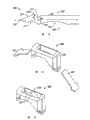
图1是本发明的缝合设备的第一优选实施例的侧视立视图;Figure 1 is a side elevational view of a first preferred embodiment of the suturing device of the present invention;
图2是第一优选缝合设备的近视图,表示大致容纳在下部爪内的可弯曲针;Figure 2 is a close up view of the first preferred suturing device showing the bendable needle generally contained within the lower jaw;
图3是第一优选缝合设备的近视图,表示穿刺组织的可弯曲针;Figure 3 is a close-up view of the first preferred suturing device showing the flexible needle piercing tissue;
图4是从组织上去除的第一优选缝合设备的近视图;Figure 4 is a close up view of the first preferred suturing device removed from tissue;
图5A是容纳可弯曲针的第一优选缝合色的爪的透视图;FIG. 5A is a perspective view of a claw receiving a first preferred suture color of a bendable needle;
图5B是图5A的透视图,表示可弯曲针前进到远端穿刺位置;Figure 5B is a perspective view of Figure 5A, showing the bendable needle advanced to the distal piercing position;
图6是第一优选缝合设备的前端视图;Figure 6 is a front view of the first preferred suturing device;
图7A是表示优选缝线接收器接收通过针承载的缝线的操作视图;Figure 7A is an operational view showing the preferred suture receiver receiving suture carried by the needle;
图7B是在针缩回之后保持缝线的图7A的优选缝线接收器的透视图;Figure 7B is a perspective view of the preferred suture receiver of Figure 7A holding the suture after needle retraction;
图8A是另一优选缝线截取的操作视图;FIG. 8A is an operational view of another preferred suture cut;
图8B是在针缩回之后保持缝线的图8A的优选缝线接收器的操作视图;Figure 8B is an operational view of the preferred suture receiver of Figure 8A holding the suture after needle retraction;
图9是包括缝线收回(retrieving)装置的缝合设备的第二优选实施例的前端视图;Figure 9 is a front view of a second preferred embodiment of a suturing device comprising a suture retrieving device;
图10A是图9的优选缝线收回装置的操作视图;Figure 10A is an operational view of the preferred suture retraction device of Figure 9;
图10B是优选缝线收回装置的操作视图,表示收回针接合缝线;Figure 10B is an operational view of the preferred suture retraction device showing the retraction needle engaging the suture;
图10C是优选缝线收回装置的操作视图,表示针收回缝线;Figure 10C is an operational view of the preferred suture retraction device showing the needle retracting the suture;
图11是第三优选缝合设备的前端视图,其中可弯曲针通过上部爪承载;Figure 11 is a front view of a third preferred suturing device with the bendable needle carried by the upper jaw;
图12是第四优选缝线收回设备的前端视图,其中可弯曲针通过上部爪承载;Figure 12 is a front end view of a fourth preferred suture retrieval device with the bendable needle carried by the upper jaw;
图13是包括固定机构的第五优选缝合设备的透视图;Figure 13 is a perspective view of a fifth preferred suturing device including a securing mechanism;
图14是第五缝合设备的前端视图;Figure 14 is a front view of the fifth suturing device;
图15是第五缝合设备的侧立视图;Figure 15 is a side elevational view of a fifth suturing device;
图16是结合固定机构的缝合爪的近视透视图;Figure 16 is a close up perspective view of a suturing jaw incorporating a securing mechanism;
图17是图16的缝合爪的尖端的顶部平面图;Figure 17 is a top plan view of the tip of the suturing jaw of Figure 16;
图18是结合可选择的固定机构的缝合爪的透视图;Figure 18 is a perspective view of a suturing jaw incorporating an optional securing mechanism;
图19是结合另一可选择固定机构的缝合爪的近视透视图;Figure 19 is a close up perspective view of a suturing jaw incorporating another alternative securing mechanism;
图20是图19的缝合爪的透视图;Figure 20 is a perspective view of the suturing jaw of Figure 19;
图21是第六优选缝合设备的局部去除的侧视立视图;Figure 21 is a side elevational view, partially broken away, of a sixth preferred suturing device;
图22是第六优选缝合设备的针承载爪的顶部平面图;Figure 22 is a top plan view of the needle carrying jaw of the sixth preferred suturing device;
图23是图22的针承载爪的透视图,其中可弯曲针表示成被覆盖,以便清楚说明;Figure 23 is a perspective view of the needle carrying jaw of Figure 22 with the bendable needle shown covered for clarity;
图24是针承载爪的透视图,其中可弯曲针表示成在对准位置上被覆盖;Figure 24 is a perspective view of a needle carrying jaw with the bendable needle shown covered in an aligned position;
图25是包括优选针致动器的第六优选缝合设备的手柄组件的透视图;以及25 is a perspective view of a handle assembly of a sixth preferred suturing device including a preferred needle actuator; and
图26是正在装载缝线的第六优选缝合设备的透视图;Figure 26 is a perspective view of a sixth preferred suturing apparatus being loaded with suture;
图27是装载有缝线的第六优选缝合设备的透视图;Figure 27 is a perspective view of a sixth preferred suturing device loaded with suture;
图28是本发明的优选可弯曲针的立视图;Figure 28 is an elevational view of a preferred bendable needle of the present invention;
图29是优选缝线接收机构的局部分解的透视图;Figure 29 is a partially exploded perspective view of a preferred suture receiving mechanism;
图30是图29的优选缝线接收机构的透视图;Figure 30 is a perspective view of the preferred suture receiving mechanism of Figure 29;
图31是包括单个倒刺的爪的透视图;Figure 31 is a perspective view of a claw including a single barb;
图32是包括一对倒刺的爪的透视图;Figure 32 is a perspective view of a claw including a pair of barbs;
图33是按照第七优选实施例的缝线穿过设备的左侧视图;Fig. 33 is a left side view of a suture passing device according to a seventh preferred embodiment;
图34是用于图33的缝线穿过设备的可弯曲针的透视图;Figure 34 is a perspective view of a bendable needle for the suture passing device of Figure 33;
图35是图34的可弯曲针的顶部平面图;Figure 35 is a top plan view of the bendable needle of Figure 34;
图36是图34的可弯曲针的左侧视图;Figure 36 is a left side view of the bendable needle of Figure 34;
图37是图33的缝线穿过设备的透视图,表示图34的可弯曲针如何装载其中;Figure 37 is a perspective view of the suture passing device of Figure 33, showing how the bendable needle of Figure 34 is loaded therein;
图38是图33的缝线穿过设备以及图34的可弯曲针的分解透视图;Figure 38 is an exploded perspective view of the suture passing device of Figure 33 and the bendable needle of Figure 34;
图39是图33的缝线穿过设备以及装载其中的图34的可弯曲针的截面侧视图;39 is a cross-sectional side view of the suture passing device of FIG. 33 with the bendable needle of FIG. 34 loaded therein;
图40是强调爪运动机构的结构和操作的简化截面侧视图;Figure 40 is a simplified cross-sectional side view emphasizing the structure and operation of the jaw kinematic mechanism;
图41是强调针展开机构的结构和操作的简化截面侧视图;Figure 41 is a simplified cross-sectional side view emphasizing the structure and operation of the needle deployment mechanism;
图42是位于缝线穿过设备的轴的远端处的固定爪的分解透视图;Figure 42 is an exploded perspective view of a securing pawl located at the distal end of the shaft of the suture passing device;
图43是图42的远端尖端的放大近视图;Figure 43 is an enlarged close-up view of the distal tip of Figure 42;
图44是与图43相对应、但是组装后的放大近视图;Figure 44 is an enlarged close-up view corresponding to Figure 43 but assembled;
图45是位于缝线穿过设备的轴的远端处的固定爪的顶部平面图;Figure 45 is a top plan view of the securing pawl located at the distal end of the shaft of the suture passing device;
图46是位于图45的远端尖端处的放大近视图;Figure 46 is an enlarged close-up view at the distal tip of Figure 45;
图47是位于缝线穿过设备的轴的远端处的固定爪的侧视图;FIG. 47 is a side view of a securing pawl located at the distal end of the shaft of the suture passing device;
图48是位于图47的远端尖端处的放大近视图;以及Figure 48 is an enlarged close-up view at the distal tip of Figure 47; and
图49a和49b-56a和56b分别是优选实施例的远端的成对透视图和顶部平面图,表示缝线经由端部细槽装载、在接合缝线时针向前平移和瞬时侧向运动、缝线环套的形成以及针缩回静置位置的总体操作。49a and 49b - 56a and 56b are a pair of perspective and top plan views, respectively, of the distal end of a preferred embodiment showing suture loading via the end slot, forward translation of the needle and momentary lateral movement when engaging the suture, seam Formation of the loop sleeve and general operation of the needle retracted to rest position.
通过参考下面的描述所述实施例的详细描述将更好理解本发明及其多个实施例。容易理解到所述实施例作为实例提出,并且不限制由权利要求最终限定的本发明。The invention and its various embodiments will be better understood by reference to the following detailed description describing said embodiments. It will be readily understood that the described embodiments are presented as examples, and do not limit the invention, which is ultimately defined by the claims.
具体实施方式 Detailed ways
缝合设备的第一优选实施例表示在图1中,并且通过参考标号10总体表示。设备10表示成具有带有近端12和远端14的细长构造。手柄组件16布置在近端12处,并且包括剪刀手柄18和21以及致动器23。一对相对爪25和27布置在远端处,并且经由细长轴或管29连接在手柄组件16上。在一个实施例中,上部爪25相对于下部爪27枢转,如图2所示。A first preferred embodiment of a suturing device is shown in FIG. 1 and is indicated generally by
在所述实施例中,下部爪27包括本发明特别感兴趣的针32。在这种情况下,针32包括经由大致平、窄小和细长构造的主体。如图1-3所示,针32由可弯曲材料形成,使其可以通过使用者拇指提供的轴向力运动,并且弯曲成90度的曲线,从而大致垂直于轴线并朝着相对上部爪25运动。应该理解到针32可以是大致直的,如图1所示,并且接着以任何角度弯曲,并且在离开轴线的方向上前进。最好包括拇指摇杆或滑块的致动器23连接在针32上。致动器23使得使用者朝着远端将针32前进到伸出的操作位置,并且朝着近端到缩回的不操作位置。In the embodiment described, the
将具有缝线34的针32穿过使得针穿过组织展开并且使其和穿过缝线一起承载。相对爪25可包括任选的接收器,接收器适用于在针32缩回到下部爪27内时从针32上去除缝线。此时,缝线延伸穿过组织并进入上部爪。如图4所示从组织去除爪使得设备10缩回,将缝线留在原位,并且打结或进一步操作。缝线接收器是任选的,这是由于组织本身可通常在针缩回时用作缝线接收器。Threading the
在此实施例中,下部爪表示在图5A中,包括细长构造以及适用于接收针32的通道36。针在此爪27的远端处弯曲并且向上经过有助于弯曲针32并使其朝着缝线接收器引导的过渡块38。虽然所述实施例表示相对于下部爪27的轴线垂直弯曲针32的过渡块38,过渡块38可构造成以大致不平行于下部爪27的轴线的任何特定角度或方向弯曲和引导针32。图5A表示针缩回,并且图5B表示针32展开并且设置细槽40,以便将缝线34承载到相对爪25。此构造该表示在图6的径向截面图中。In this embodiment, the lower jaw is shown in FIG. 5A , comprising an elongated configuration and a
在上部爪25中,缝线接收器41设置成从针32去除缝线34。金属或弹性体板片或叶片43设置成如图7A所示接合针32和穿过的缝线34。在针32如图7所示缩回时,此板片43迫使缝线34离开针细槽40。In the
在类似实施例中,针32和穿过的缝线34经由类似地接合缝线34的弹性垫45压迫,并且在针32如图8B所示缩回时使其从针细槽40上去除。In a similar embodiment, the
缝合设备的第二优选实施例表示在图9中,图9是类似于图6的截面图,但是表示用作收回器而不是承载器的针32。在此实施例中,缝线34开始通过上部爪25承载。此例中的针细槽42从针32的侧部朝着远端延伸。在此针32和细槽42如图10A所示延伸时,细槽42接合上部爪25内的缝线34。在针32缩回时,缝线收回到针细槽42内,并且穿过组织承载返回。此过程的最后步骤与参考图4描述的情况相同。A second preferred embodiment of the suturing device is shown in Figure 9, which is a cross-sectional view similar to Figure 6 but showing the
将明白的是此设备10还可与通过上部爪25承载的针32协作。这种特征表示在图11的截面图所示的第三优选实施例中,其中针32用作缝线承载器。特别是,限定在针32内的缝线细槽40包括相对于端部52朝着远端定位的开口50,使得细槽40面向接收器或下部爪27。缝线34因此通过针32朝着相对下部爪27承载。It will be appreciated that this
在图12中,缝合设备的第四优选实施例包括缝线收回装置,其中针32通过上部爪25承载。在这种情况下,针32用作缝线34的收回器。针32限定具有相对于端部56朝着近端定位的开口54的细槽42,使得细槽42背向相对下部爪27。在所示实施例中,针32的远端部分因此最好成形为钩子。In FIG. 12 , a fourth preferred embodiment of a suturing device comprises a suture retraction device in which the
缝合设备的第五优选实施例表示在图13中,并且通过参考标号110表示。在图13-15中,设备110包括具有近端112和远端114的细长构造。手柄组件(未示出)布置在近端112处,并且包括在远端114处可操作地连接在一对相对缝合爪116和118上的剪刀手柄。细长轴或管121将爪116、118连接在手柄组件上。在一个实施例中,上部爪116相对于下部爪118枢转,如图13-15所示。A fifth preferred embodiment of a suturing device is shown in FIG. 13 and is indicated by
在所示实施例中,下部爪118包括本发明特别感兴趣的保持机构123。设备110可如上所述包括手柄组件、容纳在爪116、118之一内的可弯曲针125以及包括在爪116、118的另一个内的缝线接收器。由于保持机构123用来固定地保持缝线127,同时在通过针125接合时容易使其松开,机构123最好包括在容纳针125的爪内。例如,如果针125容纳在上部爪116内,那么保持机构123也包括在上部爪116内。In the illustrated embodiment, the
第一优选固定机构123包括形成在爪118的远端尖端132处的弹簧129。弹簧129包括在其本身向后弯曲的悬臂部分134。楔形件或凹槽136限定在悬臂部分134和相对壁138之间,如图16和17更加清楚所示那样。在图13-16所示的实施例中,固定机构123与爪118形成整体。为了组装缝线127,第一端141保持在爪118之下,并且另一端143在爪118之上。端部141、143可在朝着近端的方向上拉动,使得缝线127楔入凹槽136。在布置在凹槽136内时,悬臂部分134贴靠相对壁138偏压缝线127,因此将缝线127固定夹紧就位,以便通过针125接合。The first
弹簧129的偏压力构造成使得缝线127保持固定地不与针125接合,而又可以在接合时容易松开。因此容易理解到弹簧129可包括能够贴靠相对表面邻靠、夹紧缝线127同时使其在与针接合时松开的多种机构。凹槽136最好与针出口145对准或靠近其布置,使得在端部141、143被拖动靠近时,缝线127的部分147沿着横向延伸的针125的路径定位。The biasing force of
在图18中,第二优选保持机构123a可包括与爪118a分开形成的弹簧机构129a。弹簧机构129a包括构造成安装在限定在爪118a内的细槽152配合的锚固件149。In Figure 18, the second
在图19和20中,第三优选保持机构123b包括Z形凹槽154,该凹槽在朝着近端延伸时逐渐变窄。Z形图案与朝着近端渐缩相结合以有助于缝线127朝着近端抽出时紧密配合。特别是,凹槽154的朝着近端渐缩的构造在缝线朝着近端抽出时将其保持就位,同时Z形图案防止缝线127朝着远端与爪118b脱离。In Figures 19 and 20, the third
缝合设备的第六实施例表示在图21-27中,并且通过参考标号210总体表示。设备210包括相对枢转的第一爪220和第二爪222。在图21-23中,第一爪220构造成容纳可弯曲针224。这种针承载爪220可包括设备210的任何下部或上部爪。在针224处于非操作、非穿刺位置时,可弯曲针224大致布置在第一爪220内的通道226内。A sixth embodiment of a suturing device is shown in FIGS. 21-27 and is indicated generally by
在图22中,第一爪220限定与轴向细槽231连通的开口或入口228。入口228最好设置朝着第一爪220的一侧开口的相对宽的嘴部233。这种最好横向的入口228在其接近轴向细槽231时渐缩。In FIG. 22 ,
在图23中,本发明特别感兴趣的针224表示离开原位、覆盖第一爪220以便清楚表示。在组装时,针224如上所述位于通道226内。针224包括横向细槽或缺口235(见图28)。限定缺口235的边缘最好被倒圆或平整,使其不切断缝线。如原始图28所示,针224包括限定锐利针尖端242的远端部分、限定缺口或细槽235及其相关开口的缺口或细槽部分以及限定第一远端月牙形空穴237以及相邻第二近端月牙形空穴239的第一和第二空穴部分。在原始图28的优选针中,限定锐利针尖端242的远端部分通过针轴线相等地分叉。如图28进一步所示,限定细槽235的细槽部分限定底部和与底部横向延伸的通道,优选的底部构造成圆形,具有大约通道宽度的直径。空穴237、239总体在缺口235的任一侧、在针224的较大长度上提供分散的柔性,使得在针224弯曲时,所有应力不在缺口235处集中。缺口235最好布置在空穴237和239之间。如原始图28进一步所示,第一空穴237成形为具有第一半径和第一轴向长度的月牙形,第二空穴239成形为具有大于第一半径的第二半径和大于第一轴向长度的第二轴向长度。In Figure 23, the
在静置状态,如原始图23所示,针224大致是直的,并且可相对于入口228偏压到任何静置位置。例如,静置位置可包括如图23所示相对于入口228朝着远端布置或者相对于入口228朝着近端布置的缺口235。为了装载缝线,针224运动的装载位置,由此缺口235如图24所示与入口228对准。如果针224被偏压使得缺口235相对于入口228在远端处,对准通过相对于第一爪220在朝着近端方向上运动针224来实现。因此,如果针224被偏压,使得缺口235相对于入口228在近端处,对准通过相对于第一爪220在朝着远端方向上运动针224来实现。图25表示缝合设备210的优选手柄组件243。在图25中,手动操作致动器244连接在针上以便其朝着近端和远端运动。在所示实施例中,致动器244最好包括拇指杆或摇杆,摇杆通过使用者的拇指向后摇动,由此朝着近端运动针以便将缺口与入口对准,并且向前运动,由此朝着远端前进针。In the rest state, as shown in the original FIG. 23 , the
图26表示装载到设备210上的缝线246。缝线246形成环套并且引导到入口228。在缝线246在第一爪220上保持略微张紧时,缝线246进入入口228并且布置在针的缺口内。图25所示的手指滑块可松开,由此朝着远端将针和被截获的缝线246偏压到图27所示的静置位置。将理解到第一爪220的轴向细槽231使得被截获缝线246在其通过针224承载时自由运行。FIG. 26 shows suture 246 loaded onto
过渡块块248设置在第一爪220的远端部分处,并且可与爪220形成整体或与其分开。过渡块248可适用于弯曲针,并且使其以任何所需角度引导,在所示实施例中表示为大致垂直于第一爪220的轴线。A
在图26和27中,第二爪222包括限定具有侧开口255的孔口253远端钩子251。在爪220、222夹紧在组织上时,孔口253构造成使得针在穿刺组织之后穿过。在针224缩回时,组织通过保持在缝线246上而用作缝线接收器,同时针224缩回。这在与爪222接触的组织的侧部上形成缝线246的环套或自由线。钩子252可接着放置在环套中并且被拉动。作为选择,两个爪220、222可抓握在缝线的自由线上,并且拉动穿过组织。在图25中,固定手指支承件257用来致动器244的反作用板。In FIGS. 26 and 27 , the
在图28中,优选的可弯曲针224包括通过防止组织被针224的任何部分阻挡或截获而有助于平滑穿刺组织的远端几何形状。针224包括缺口侧259和相对的空穴侧262。特别是,针224包括相对于限定缺口235的缺口边缘朝着近端定位的直缺口侧边缘264。针224还限定大致平行于缺口侧边缘264延伸的针轴线“A”。In FIG. 28 , the preferred
在针224穿刺组织时,组织将沿着通向在限定缺口235的缺口边缘远端布置的远端突出部268的缺口侧斜面266运行。如所示,远端缺口边缘从底部并横向离开轴线延伸第一距离,近端缺口边缘横向离开底部并且横向离开轴线延伸小于第一距离的第二距离。将理解到远端突出部268离开轴线“A”离开横向距离“B”,而近端突出部271离开轴线“A”横向距离“C”。在优选实施例中,距离“B”大于距离“C”,使得远端突出部268向外推动穿刺组织,以有助于保持组织不截获在缺口235内。当组织在缺口235上运行时,与近端突出部271相关的大致倒圆的斜面进一步防止组织变得被阻挡。As
在相反的空穴侧262上,第一和第二空穴边缘第一和第二空穴237、239,在针224弯曲时在针224上并围绕缺口235限定更加均匀的分配应力,使得应力靠近缺口235最小。朝着缺口235的开口朝着远端指向,在穿过组织展开时,使得缝线被迫进入针,并且在针缩回时,使得缝线容易松开。On the
缝线接收器280的另一优选实施例表示在图29和30中。接收器280可例如通过与容纳针的爪相对的爪来承载。缝线接收器280包括布置在接收器壳体284内的一对板片或叶片282。叶片282最好构造成在夹紧点286处相互邻靠,如图30所示,使得针在其之间运行,同时在针缩回时保持承载的缝线。如上所述,采用缝线接收器是任选的,这是由于被穿刺组织本身可通常用作缝线接收器。特别是,在承载缝线的针已经穿刺组织之后,被穿刺的组织通常足以在针缩回时保持环套形式的缝线。Another preferred embodiment of
在图31中,钩子或倒刺291的第一优选实施例形成在最好是与容纳可弯曲针的第一爪相对的第二爪的爪的远端处。倒刺291构造成在可弯曲针缩回之后钩住通过组织本身保持的环套缝线。在图32中,爪的远端可另外形成一对倒刺293。In Figure 31, a first preferred embodiment of a hook or
所示实施例总体表示缝线穿过领域的显著进步,这是由于它们使得缝线保持在递送到手术部位的装置内,并且特别是经由分节孢子套管,如果需要,使得组织被抓握和重新抓握,并且使得通过往复运动的可弯曲针将缝线推过组织。但是,在如何将缝线装载到穿过器以便通过针截获、针的构造以及针展开的总体简化来说还可以进行改进。The illustrated embodiments generally represent a significant advance in the field of suture passing, as they allow the suture to remain within the device delivered to the surgical site, and in particular via the arthroplasty cannula, allow the tissue to be grasped if desired and re-grasp, and allow the suture to be pushed through the tissue by the reciprocating, flexible needle. However, improvements can also be made in how the suture is loaded into the passer for capture by the needle, the configuration of the needle, and the overall simplification of needle deployment.
图33-48涉及新型的、第七当前优选实施例,该实施例增加了多个显著进步。Figures 33-48 relate to a novel, seventh presently preferred embodiment which adds a number of significant advances.
图33是新型缝线穿过设备310的侧视图,并且图34-36表示用于缝线穿过设备310的改进的可弯曲针400。如图33所示,缝线穿过设备310通常包括定位在近端312处的手柄组件320、从手柄组件320延伸的细长轴330以及通过在细长轴330的远端340处支承的一对爪340、350形成的抓握机构以及爪运动机构360和相关棘轮锁栓组件370(下面更加完整描述)。优选手柄组件320由两个半件形成,即通过多个螺钉323保持在一起的左半件321和右半件322(未示出),并且细长轴220通过在轴330近端处接合缺口(未示出)的手柄-轴销324保持在两个半件之间。爪包括固定爪340和可动爪350。可动爪350如所示通过爪-轴销352枢转地固定在轴的远端上。FIG. 33 is a side view of the novel
如图33进一步所示,并且如下面更加完整描述,新型缝线穿过设备310包括两个机构,即用于开启和闭合爪组件的爪运动机构360(以及相关的棘轮锁栓组件370)和用于前后平移针的针运动机构380。As further shown in FIG. 33 , and as described more fully below, the novel
爪运动机构360开启和闭合可动爪350,并且通过爪触发器361操纵。在先的实施例需要医生在开启和闭合方向上主动地运动爪。为了简化此实施例中的使用,可动爪350被任选地偏压开启,并且接着在医生挤压爪触发器361时相对于固定爪340朝着闭合位置运动。另外,爪运动机构360可任选地包括超级弹性的元件,该元件在载荷下变形以便限制爪闭合力。
如上所述,棘轮锁栓组件370与爪运动机构360相关。优选的棘轮锁栓组件370的操作性能是显然的,其中它锁定而不通过使用者可靠动作,但是可以通过松开按钮的尖端按压来失效,并且都不需要使用者改变手的位置。特别是,接着爪致动器361被拉动,棘轮锁栓组件370的运动部分373自由运动到手柄组件320内,但是要经由下面更加完整描述的机械相互作用,防止爪触发器361返回到开启位置,直到随后松开为止。为此,优选的棘轮锁栓组件370经由棘轮松开或手指垫371,使得棘轮锁栓住370在没有载荷施加在手指垫371时用作棘轮,同时手指垫371的简单按压松开棘轮锁栓组件370,并使得医生根据需要改变爪触发器361和可动爪350的位置(例如在缝线放置之前根据需要重新定位爪),并且如果可以,返回到其开启位置。As noted above, the
图34-36表示用于图33的缝线穿过设备的可弯曲针400。出于参考目的,针400具有近端412和远端414。如所示,针400由具有带细槽远端402的近端针主体401和位于针主体401的带细槽远端402内并焊接其上的平的可弯曲延伸部403形成。可弯曲针400的远端414类似于前面图28的优选针,其中它具有针尖端404、位于其侧部的针缺口405以及尖端404和缺口405之间的缺口侧斜面406。但是,当前优选的针400单独与缝线穿过设备协作,以便以新颖方式(下面描述)装载缝线,并且它包括某些新型构造特征,使其更容易使用,并且更加安全。34-36 show a
此时集中在构成新型构造的差别上,可以看出所述针主体在其近端处具有直角弯曲,接合拇指朝着致动器的孔口(见例如图25),而针400可包括位于其近端412的塑料突片406,以用作近端装载标示。优选的塑料突片406由HDPE、聚乙烯制成,并且以公知方式形成在针主体401上,但是可以任何适当材料和或组装方法。Focusing now on the differences that make up the novel configuration, it can be seen that the needle body has a right angle bend at its proximal end engaging the thumb towards the aperture of the actuator (see e.g. FIG. 25 ), whereas the
塑料突片406提供某些独特优点。首先,它提供方便的手指抓握部,以便将可弯曲针400装载到缝线穿过器310内。另外,在高压蒸煮时它任选地熔化,由此有效地增加患者的安全性,防止针400的重新使用。
图37是优选缝线穿过设备310和装载到缝线穿过设备内的可弯曲针400的局部分解透视图。特别是,虚线表示针400如何经由位于手柄组件320的顶侧的腔室325装载到细长轴330的尾部或近端内。如参考其它附图更加完整描述那样,在针400完全插入细长轴330之后,装载标示406被下压到针接收器390内。针接收器390通过医生操纵针触发器381而前后运动。37 is a partially exploded perspective view of the preferred
图38是优选缝线穿过设备310和可弯曲针400的完全分解的透视图。这里,可以看出包括爪运动机构360、棘轮锁栓组件370和针运动机构380的部件的优选装置的详细构造。为了便于描述,以上机构将参考图39-41描述,并与图38的完全分解的透视图结合考虑。FIG. 38 is a fully exploded perspective view of the preferred
图39-41是缝合设备310和装载其中的可弯曲针400的截面侧视图。图39是完整的截面图,而图40和41有选择地省略某些其它部件,或者只以虚线表示它们,以便强调爪运动和针运动机构360、380的构造和操作。39-41 are cross-sectional side views of the
图40通过以虚线表示总体设备310并且通过有策略地去除与针运动机构380相关的部件来集中在爪运动机构360和相关的棘轮锁栓组件370上(见图42)。如所示,爪运动机构360包括爪触发器361、爪触发器销362、爪触发器推杆363、爪杆簧364、连杆365、致动器368以及最后可动爪350本身。在操作中,在爪触发器361被挤压时,它围绕爪触发器销362沿着弧形J1枢转,并且爪触发器推杆363压缩爪杆簧364,爪杆簧如上所述趋于在开启位置上偏压爪触发器361、可动爪350以及整体爪运动机构360。FIG. 40 focuses on the
在爪触发器361沿着弧形J1运动时,爪触发器362的上部运动经过相应的、但较小半径的弧形J2。在其附近,触发器-连杆销366将爪触发器361连接在连杆365上,并且进一步下游,连杆-致动器销367将连杆365连接在致动器368上。经由这一系列连接,致动器368沿着弧形J1和J2的致动运动转换成致动器368沿着箭头J3的平移运动。如图38、39和40清楚所示,细长轴330设置多个引导销331(每侧两个)以及沿着其长度延伸的致动器通道333。致动器368在轴的致动器通道333内前后滑动。As
致动器368继而经由略微位于可动爪350绕其转动的爪-轴销352之下的致动器-爪销351连接到可动爪350的下部上。因此,在爪触发器361沿着弧形J1受到挤压时,触发器361的上部沿着弧形J2运动,致动器368沿着箭头J3平移,可动爪350的近端沿着弧形J4转动,并且可动爪350的远端沿着弧形J5转动,即朝着闭合方向运动。The
图40还表示优选的棘轮锁栓组件370,该组件包括手指垫371、经由倾斜齿374的运动部分373以及同样具有倾斜齿378的分开的固定部分377。棘轮锁栓组件同样包括提供小弹簧力以便贴靠固定部分377的倾斜齿378偏压运动部分373的倾斜齿374的棘轮锁栓弹簧375。棘轮锁栓组件370防止通过爪杆推杆363以及爪杆簧364偏压到开启位置上的爪触发器361运动到开启位置,直到需要为止。特别是,在爪触发器沿着弧形J1在逆时针方向上挤压以便闭合可动爪350时,倾斜齿374容易在倾斜齿378上滑动,但是齿374、378趋于锁定在一起,一部分防止爪触发器361在顺时针方向上返回,并且开启可动爪350。在医生希望开启可动爪350时,他简单按压手指垫371,将可动部分373上的倾斜齿摇动离开固定部分377上的倾斜齿378。此时,爪弹簧365趋于开启爪运动机构360,如同通过手指垫371上的医生手指控制那样。新型手柄机构的另一有利的方法是“根据需要的棘轮”特征。在优选实施例中,此特征通过将棘轮按钮和手指垫371放置在爪触发器361的上部上来提供。这使得医生通过用手指改变他如何抓握手柄来选择是否使用锁定特征,挤压爪触发器361而不按压手指垫371,使得棘轮锁栓组件370自然接合,而在手指垫371上用轻微但连续的手指压力运动爪触发器361使得爪350充分开启和闭合,而不接合棘轮锁栓组件370。为了经由爪触发器361的运动,通过改变施加在手指垫371上的压力而使得医生根据需要使得棘轮锁栓组件有效或失效,影响手指垫371的棘轮锁栓弹簧375的弹簧力小于影响总体爪触发器361的爪杆簧364的弹簧力。FIG. 40 also shows a preferred
图41通过有策略地去除与爪运动机构360和棘轮锁栓组件370的相关部件来集中在以虚线表示的总体设备310中的针运动机构380上(见图41)。如所示,针运动机构380包括针触发器381、触发器齿条384、针弹簧386、齿轮387、具有针接收器384的针齿条388以及最后是针400。针触发器381如所示通过帽螺钉382和销384连接在针齿条384上。每个齿条384、388包括相应的齿条引导件385、389,提供小表面面积的接触表面以便运动。Figure 41 focuses on the
针弹簧386在非展开或静置状态偏压针,如图41所示。在操作中,在触发器齿条384沿着箭头N1(朝着右侧)朝着装置310的近端312平移时,齿轮387沿着箭头N2(朝着左侧)朝着装置310的远端314平移针齿条388和针。在针400朝着远端312平移时,它运动穿过固定爪340内的针通道343,并且最终向上弯曲,其中它沿着箭头N3临时从下部固定爪340延伸。
针弹簧386必须提供足够的弹簧力以便在针触发器381松开时自动缩回针400。并且,医生必须在挤压针触发器381时克服此弹簧力,以便展开针400。因此,希望的是减小所需的弹簧力,以便减小或甚至消除重复驱动造成的手疲劳。为此,优选的针400涂覆光滑涂层,使其容易在装置310以及患者组织内前后滑动针400。此光滑涂层减小针的摩擦系数,并由此降低缩回针400所需的弹簧力。通过将所需的弹簧力减小大约20%,使用光滑涂层使得缝合装置310更加容易使用。优选的涂层是固化的聚四氟乙烯(PTFE)涂层,但是任何其它含氟聚合物或超低纯固体(ultra-low sheer solid)也是足够的。针400可通过将其简单浸入PTFE颗粒的容器来涂覆,这些颗粒悬浮在适当溶剂中(在针从悬浮物中去除之后溶剂闪蒸,并且留下PTFE涂层)。但是最好是,针400在涂覆之后被热固化,以便熔化PTFE本身,并且形成更加耐磨涂层。
图42-48总体集中在缝线装载和展开配置的独特结构,如新型缝合设备的下部爪340中体现那样。如图42-48所示,下部或固定爪340位于细长轴330的远端处。在此优选的实施例中,固定爪340由与细长轴330相同的原料整体形成的下部爪主体341与总体成形为雪橇尖端的爪插入件342相结合地形成。在组装过程中,爪插入件342以例如焊接的任何适当方式落入并固定在下部爪主体341上。42-48 generally focus on the unique structure of the suture loading and deployment configuration, as embodied in the
爪插入件342有助于限定在展开过程中向前并接着向上引导针400的针通道343。特别是,如图43以及图44和48清楚所示,爪插入件342最终静置在围绕已经形成在下部爪主体内的针通道343的底部和侧壁的一对突出部(ledge)349上(只看到一个)并横跨这些突出部。基本上,爪插入件342的底部用作针通道343的天花板。如斜面更加详细描述那样,针400(图42-48)水平平移穿过针通道343,包括将针朝着通道出口344向上引导并最终离开通道出口的曲线。
图42-48还表示与缝线(未示出)开始装载的独特构造。特别是,下部爪340具有叉形远端345,包括设置成端部细槽346的缝线装载入口,细槽346通向容纳在下部爪主体341和爪插入件342内的缝线细槽347。在缝线通过针拾取时展开之前,缝线细槽347朝着近端终止于其中定位缝线的近端缝线保持节点或细槽端部348,如下面进一步详细描述那样,并且缝线的环套穿过保持在爪之间的组织。Figures 42-48 also illustrate the unique configuration of initial loading with sutures (not shown). In particular, the
在此实施例中,如图44和46清楚所示,缝线细槽37沿着其长度具有变化尺寸,以便相对于将被展开的缝线在细槽的多个部分内提供摩擦。因此,这些尺寸相对于通过装置310穿过的缝线变化。当前优选的装置旨在用于一定范围的缝线,从#2缝线到#2-0缝线。较厚的#2缝线具有大约0.5mm或大约0.0196”的公称直径,并且较薄的#2-0缝线具有大约0.3mm或大约0.0118”的公称直径。所有其它尺寸将是英寸的。虽然此实施例可适应特定范围的缝线尺寸,例如#2到#2-0缝线,该尺寸可以根据调节,以便适应传统缝线尺寸或传统缝线尺寸的范围。In this embodiment, as best seen in Figures 44 and 46, the
虽然这是示例性实施例,并且下面本发明的原理可以变化以使用不同尺寸的缝线,此实施例的尺寸的详细考虑会有助于读者。在靠近缝线装载入口或端部细槽346的位置“a”处,该宽度大于缝线的直径,使得缝线容易被拉入端部细槽346并进入缝线细槽347。在针通道343的垂直部分的任一侧上延伸的位置“b”处,宽度是0.24±0.01使得#2缝线继续自由穿过分度通道347的此部分。在位置“c”处,缝线通道347的宽度变窄到0.20±0.01,使得通道开始与缝线的公称直径紧密符合。在位置“d”处,缝线通道347进一步变窄到0.19±0.01,使得在通道347和缝线之间存在摩擦。并且最后,在缝线被拉出到缝线通道347的端部并且进入其近端缝线保持节点348时,宽度扩张到0.26±0.01,由此使得医生在缝线展开到手术部位之前根据需要对缝线垂直调节。通常,医生将留下下部爪340的下侧之下延伸的缝线的相对短的接头,使得在装置经由组织穿过缝线的环套之后,在保持单股缝线之前,只有所述数量的缝线通过随后在环套上拉动而拉过组织。此外,在装置310从手术部位缩回之后,它马上准备重新装载缝线,这是由于图41所示和如上所述的针弹簧将针自动缩回到非展开和静置状态,并且将其偏压在该位置上,由此可以装载新的缝线。While this is an exemplary embodiment, and the principles of the invention below may be varied to use sutures of different sizes, a detailed consideration of the dimensions of this embodiment will assist the reader. At location "a" near the suture loading inlet or
图49a和49b-56a和56b是表示优选实施例的某些结构差别和总体操作的一系列成对附图。特别是,这些附图表示总体操作,从缝线经由缝线装载入口或端部细槽装载、针在其接合缝线时向前平移和瞬时侧向运动、穿过目标组织的缝线环套形成(组织被省略以便清楚说明)以及针缩回到静置位置。Figures 49a and 49b-56a and 56b are a series of paired drawings showing certain structural differences and general operation of the preferred embodiment. In particular, these figures represent the overall operation, from suture loading via the suture loading inlet or end slot, forward translation and momentary lateral movement of the needle as it engages the suture, through the suture loop through the target tissue Formation (tissue omitted for clarity of illustration) and needle retracted to rest position.
图49a和49b表示针400在缩回或静置状态时针400相对于缝线细槽347和近端缝线保持节点(node)348的位置。Figures 49a and 49b illustrate the position of
图50a和50b表示一段长度的缝线34被开始拉过端部细槽346并进入缝线细槽347。通常,可动爪350在缝线34装载之前或者至少在组织310引入手术部位之前闭合,但是这里可动爪350一致地表示在开启位置,以便简化视图。Figures 50a and 50b show a length of
图51a和51b表示被更深地拉入缝线细槽347的缝线34。此时,在此特定实施例中,缝线34被拉入缝线细槽347的占据非线性路径并且开始变窄的部分(见图44和46以及相关描述)。此几何形状和等同形状提供足够的摩擦以便在展开过程中将缝线保持在缝线细槽347内。51a and 51b show the
图52a和52b表示在缝线细槽347端部处完全装载到近端缝线保持节点348内的位置处的缝线34。在此实施例中,通过在图51a和51b之间前后观看可以清楚看出,缝线细槽347的非线性几何形状还造成针尖端404横向褶皱到缝线细槽347的侧部,使得缝线34朝着缝线细槽347的近端拉动时不在尖端404上悬挂。此配置有利地防止缝线34在其装载时被切断。同样,如图52b清楚所示,在缝线34相对于增加尖端404朝着近端安全定位之后,针的侧向和横向提供指向右侧(附图向上)的轻微弹簧力。这将缝线34挤压在针的缺口侧下面406和近端缝线保持节点348的相对部之间,由此有助于在放置之前将缝线保持就位,而不需要医生的任何进一步动作。以上配置构成在展开之前将缝线34保持在缝线细槽347内的装置。其它适当的结构可以用来实现这种保持功能,当然包括但不局限于挤压或夹紧配置、摩擦配置、缝线直径和缝线细槽尺寸之间的紧密关系等。52a and 52b show
继续参考图53-56的其它部分,请注意到在针400展开以及缝线34放置之前或期间该组织通常夹紧在下部爪340和可动爪350之间。换言之,在针展开过程中,可动爪350通常部分闭合,与所示的完全开启不同。但是,为了保持类似于图49-52的图53-56并且说明所示内容,组织被省略,并且可动爪350表示成处于弯曲开启位置。With continued reference to the remainder of FIGS. 53-56 , note that the tissue is generally clamped between
图53a和53b表示在针400相对于具有针触发器382的装置的远端向前平移时(见图41)针400相对于下部爪340的、缝线细槽347的位置。如图53b所示,缝线通道343(还可参考图48的侧视图)包括偏移缓解器(relief)349,使得针400在向前滑动经过缝线34时朝着左侧偏移。Figures 53a and 53b show the position of the
图54a和54b表示针400向前运动到其针缺口405与近端缝线保持节点348以及容纳其中的缝线的中间部分对准的点处之后的不同部件的位置。由此,针的缺口侧斜面406离开缝线34,使得针400弹回到右侧,并且缝线34的中间部分通过针缺口405围绕或截获。Figures 54a and 54b show the positions of the various components after the
图55a和55b表示针400和针缺口405围绕下部爪的针通道343的曲线弯曲之后的系统,由此将缝线34的环套承载到离开下部爪340的针出口344。如果组织保留在下部和上部爪340、350之间,那么此缝线343的环套将被推过或穿过组织。55a and 55b show the system after the
图56a和56b最后表示自动返回到上部爪340的针通道343内的内部静置状态之后的针400。在此位置上,即在穿过缝线之后,整个缝线穿过装置310可简单朝着近端拉动离开手术部位,缝线340的环套滑动离开装置310的远端处的端部细槽346。缝线穿过装置310的爪340、350或者分开钳子组可接着用来将缝线34的环套拉过组织。注意到如果医生希望,装置310准备自动地将另一段缝线34装载到端部细槽346,以便另一缝线穿过操作。FIGS. 56 a and 56 b finally show the
在所有实施例中,应该理解到可以采用一次性针。因此,应该理解到提供一种系统或套件,其中缝合设备(不包括针)可重新使用,而更换一次性针。In all embodiments, it should be understood that disposable needles may be used. Accordingly, it should be appreciated that a system or kit is provided wherein the suturing device (not including the needle) is reusable while the disposable needle is replaced.
本领域普通技术人员将可以进行多种改型和变型,而不偏离本发明的精神和范围。因此,必须理解到所示实施例只出于实例的目的提出,并且它们不限制由随后权利要求限定的本发明。例如,虽然权利要求的元件以某些组合的形式提出,必须理解到本发明包括较少、较多或者不同的披露元件的其它组合。Various modifications and variations will occur to those skilled in the art without departing from the spirit and scope of the invention. Therefore, it must be understood that the embodiments shown are presented for the purpose of example only and that they do not limit the invention as defined by the following claims. For example, although the claimed elements are presented in certain combinations, it must be understood that the invention encompasses lesser, greater or other combinations of the disclosed elements.
说明书中所使用的、用来描述本发明及其多个实施例的词汇不仅以其通常限定的含义理解,而且通过此说明书中的特征限定来包括它们所代表的单一种类的普通结构、材料或者动作。The terms used in this specification to describe the present invention and its various embodiments are not only to be understood in their commonly defined meanings, but also to include the single kind of common structure, material, or action.
因此说明书的以下权利要求的词汇或元件的定义不仅包括文字上提出的元件组合。因此在此方面,考虑到对于斜面权利要求中的任何一个元件可以进行两个或多个元件的等同替代,或者单个元件可以通过权利要求中的两个或多个元件替代。虽然以上描述的元件在某些组合中起作用并且最初由此要求保护,应该理解到来自于要求保护的组合的一个或多个元件在某些缺口下可以从该组合中排除,并且要求保护的组合可针对分组合或者分组合的变型。The definitions of words or elements in the following claims of the specification therefore include not only combinations of elements stated literally. In this regard, therefore, it is contemplated that for any one element in a claim, an equivalent substitution of two or more elements may be made, or that a single element may be replaced by two or more elements in a claim. Although the elements described above function in certain combinations and are initially claimed thereby, it should be understood that one or more elements from a claimed combination may be excluded from that combination, with certain gaps, and that the claimed A combination can be for a sub-combination or a variation of a sub-combination.
本领域的普通技术人员理解的偏离要求保护的主题的细微变化(不管是已知或者随后想到的)应该在权利要求范围内等同地考虑。因此,本领域普通技术人员现在或以后知道的明显替代被限定为在限定的元件的范围内。Minor departures from the claimed subject matter (whether known or subsequently devised) that are understood by those of ordinary skill in the art are to be considered equally within the scope of the claims. Therefore, obvious substitutions now or later known to one of ordinary skill in the art are intended to be within the scope of the defined elements.
因此应该理解为权利要求包括上面特别描述和说明的、概念上等同的、可以明显替代的以及结合本发明基本思想的内容。Therefore, it should be understood that the claims include what is specifically described and illustrated above, what is conceptually equivalent, what can be obviously replaced, and what combines the basic idea of the present invention.
Claims (44)
Applications Claiming Priority (2)
| Application Number | Priority Date | Filing Date | Title |
|---|---|---|---|
| US11/738,129 US7879046B2 (en) | 2001-10-01 | 2007-04-20 | Suturing apparatus and method |
| US11/738129 | 2007-04-20 |
Related Child Applications (1)
| Application Number | Title | Priority Date | Filing Date |
|---|---|---|---|
| CN201110048651.4A Division CN102144933B (en) | 2007-04-20 | 2008-04-21 | Suturing apparatus and method |
Publications (2)
| Publication Number | Publication Date |
|---|---|
| CN101297765A true CN101297765A (en) | 2008-11-05 |
| CN101297765B CN101297765B (en) | 2011-04-20 |
Family
ID=39709226
Family Applications (2)
| Application Number | Title | Priority Date | Filing Date |
|---|---|---|---|
| CN2008100915768A Expired - Fee Related CN101297765B (en) | 2007-04-20 | 2008-04-21 | Suturing apparatus and method |
| CN201110048651.4A Expired - Fee Related CN102144933B (en) | 2007-04-20 | 2008-04-21 | Suturing apparatus and method |
Family Applications After (1)
| Application Number | Title | Priority Date | Filing Date |
|---|---|---|---|
| CN201110048651.4A Expired - Fee Related CN102144933B (en) | 2007-04-20 | 2008-04-21 | Suturing apparatus and method |
Country Status (6)
| Country | Link |
|---|---|
| US (5) | US7879046B2 (en) |
| EP (3) | EP3251608A3 (en) |
| JP (3) | JP4900727B2 (en) |
| CN (2) | CN101297765B (en) |
| AU (1) | AU2008201703A1 (en) |
| CA (2) | CA2629584C (en) |
Cited By (12)
| Publication number | Priority date | Publication date | Assignee | Title |
|---|---|---|---|---|
| CN101874746A (en) * | 2009-04-29 | 2010-11-03 | Tyco医疗健康集团 | System and method for making tapered looped suture |
| CN102551823A (en) * | 2010-08-30 | 2012-07-11 | 德普伊米特克公司 | Anchor driver with suture clutch |
| CN102846345A (en) * | 2011-05-06 | 2013-01-02 | 赛特里克斯整形公司 | Suture passer devices and methods |
| CN104161566A (en) * | 2014-08-12 | 2014-11-26 | 厦门大博颖精医疗器械有限公司 | Meshing pincers |
| US8911456B2 (en) | 2007-07-03 | 2014-12-16 | Ceterix Orthopaedics, Inc. | Methods and devices for preventing tissue bridging while suturing |
| CN107548295A (en) * | 2014-12-30 | 2018-01-05 | 瑟吉玛蒂克斯公司 | Laparoscopic stapling device with pulse deployment |
| CN107661127A (en) * | 2013-02-22 | 2018-02-06 | 益安生医股份有限公司 | Systems and methods for percutaneous suture delivery |
| CN108778151A (en) * | 2016-03-02 | 2018-11-09 | 爱德华兹生命科学公司 | System and method for disposing sutures |
| CN109199485A (en) * | 2017-06-29 | 2019-01-15 | 美多斯国际有限公司 | The suture wire box of surgical device is connected for suture |
| CN109843187A (en) * | 2016-10-31 | 2019-06-04 | 史密夫和内修有限公司 | Suture passer and grabber instrument and method |
| CN113598854A (en) * | 2021-08-05 | 2021-11-05 | 钱晓云 | Nasal septum suturing device |
| CN117224178A (en) * | 2023-09-05 | 2023-12-15 | 南京思脉德医疗科技有限公司 | Stitch assembly and stitching device |
Families Citing this family (115)
| Publication number | Priority date | Publication date | Assignee | Title |
|---|---|---|---|---|
| US8353091B2 (en) * | 2004-08-02 | 2013-01-15 | Global Pathogen Solutions, Inc. | Stun gun dart active retrieval system |
| CN101242785B (en) | 2005-06-20 | 2010-11-03 | 苏图诺有限公司 | Device for applying knots to sutures |
| US7572265B2 (en) * | 2006-03-21 | 2009-08-11 | Biomet Sports Medicine, Llc | Method and apparatus for passing a suture |
| US20080154299A1 (en) * | 2006-12-08 | 2008-06-26 | Steve Livneh | Forceps for performing endoscopic surgery |
| EP2134266B1 (en) | 2007-03-29 | 2024-12-25 | Nobles Medical Technologies, Inc. | Suturing devices for closing a patent foramen ovale |
| US8500809B2 (en) | 2011-01-10 | 2013-08-06 | Ceterix Orthopaedics, Inc. | Implant and method for repair of the anterior cruciate ligament |
| US9211119B2 (en) | 2007-07-03 | 2015-12-15 | Ceterix Orthopaedics, Inc. | Suture passers and methods of passing suture |
| US20110130773A1 (en) * | 2007-07-03 | 2011-06-02 | Saliman Justin D | Methods for continuous suture passing |
| US8702731B2 (en) | 2007-07-03 | 2014-04-22 | Ceterix Orthopaedics, Inc. | Suturing and repairing tissue using in vivo suture loading |
| US10441273B2 (en) | 2007-07-03 | 2019-10-15 | Ceterix Orthopaedics, Inc. | Pre-tied surgical knots for use with suture passers |
| US20090012538A1 (en) * | 2007-07-03 | 2009-01-08 | Justin Saliman | Methods and devices for continuous suture passing |
| US8821518B2 (en) * | 2007-11-05 | 2014-09-02 | Ceterix Orthopaedics, Inc. | Suture passing instrument and method |
| US8663253B2 (en) | 2007-07-03 | 2014-03-04 | Ceterix Orthopaedics, Inc. | Methods of meniscus repair |
| US9861354B2 (en) | 2011-05-06 | 2018-01-09 | Ceterix Orthopaedics, Inc. | Meniscus repair |
| US9314234B2 (en) | 2007-07-03 | 2016-04-19 | Ceterix Orthopaedics, Inc. | Pre-tied surgical knots for use with suture passers |
| EP2030575A1 (en) * | 2007-08-27 | 2009-03-04 | Arthrex Inc. | Suturing instrument with dual needles |
| EP2033583B1 (en) * | 2007-08-27 | 2013-03-13 | Arthrex, Inc. | In-line suture passer |
| EP2042104B1 (en) * | 2007-09-29 | 2011-10-26 | Richard Wolf GmbH | Surgical suturing instrument |
| US8603112B2 (en) * | 2007-11-30 | 2013-12-10 | Easylap Ltd. | Suturing assembly and method |
| WO2010019973A1 (en) * | 2008-08-19 | 2010-02-25 | A.M.I. Agency For Medical Innovations Gmbh | Surgical device |
| EP2184015B1 (en) * | 2008-11-07 | 2019-12-25 | Arthrex, Inc. | Suturing instrument for passing multiple sutures |
| US20100121337A1 (en) * | 2008-11-13 | 2010-05-13 | Pandya Rajiv D | Device for drilling angled osteal tunnels |
| US8282656B2 (en) * | 2009-05-28 | 2012-10-09 | Karl Storz Gmbh & Co. Kg | Suture passing instrument |
| US8469974B2 (en) * | 2009-07-15 | 2013-06-25 | Pivot Medical, Inc. | Method and apparatus for treating a hip joint, including the provision and use of a novel suture passer |
| US9198655B2 (en) | 2009-07-15 | 2015-12-01 | Pivot Medical, Inc. | Method and apparatus for treating a hip joint, including the provision and use of a novel suture passer |
| DK200970073A (en) | 2009-07-22 | 2011-01-23 | Coloplast As | Suturing system and assembly |
| US8342378B2 (en) | 2009-08-17 | 2013-01-01 | Covidien Lp | One handed stapler |
| US20110060350A1 (en) * | 2009-09-04 | 2011-03-10 | Cost Containment, Inc. | Suture passer device and suture needle |
| US9011454B2 (en) | 2009-11-09 | 2015-04-21 | Ceterix Orthopaedics, Inc. | Suture passer with radiused upper jaw |
| US11744575B2 (en) | 2009-11-09 | 2023-09-05 | Ceterix Orthopaedics, Inc. | Suture passer devices and methods |
| JP5719374B2 (en) * | 2009-11-09 | 2015-05-20 | セテリックス オーソピーディクス インコーポレイテッド | Device, system, and method for repairing a meniscus |
| US9848868B2 (en) | 2011-01-10 | 2017-12-26 | Ceterix Orthopaedics, Inc. | Suture methods for forming locking loops stitches |
| WO2011087725A1 (en) * | 2009-12-22 | 2011-07-21 | Wilson-Cook Medical, Inc. | Medical devices and methods for suturing tissue |
| US8313509B2 (en) * | 2010-01-19 | 2012-11-20 | Covidien Lp | Suture and retainer assembly and SULU |
| CA2728905C (en) * | 2010-01-20 | 2014-07-29 | Jeffrey Wyman | Suture passer assembly |
| US8940000B2 (en) | 2010-05-12 | 2015-01-27 | Covidien Lp | Surgical instruments with flexible member attachment structures |
| US8795152B2 (en) | 2010-09-13 | 2014-08-05 | Boston Scientific Scimed, Inc. | Devices and methods for delivering sutures and implants |
| US9913638B2 (en) | 2011-01-10 | 2018-03-13 | Ceterix Orthopaedics, Inc. | Transosteal anchoring methods for tissue repair |
| USD651311S1 (en) | 2011-01-11 | 2011-12-27 | Medicine Lodge, Inc. | Handle for a surgical instrument |
| US8864777B2 (en) | 2011-01-28 | 2014-10-21 | Anchor Orthopedics Xt Inc. | Methods for facilitating tissue puncture |
| AU2012225668A1 (en) * | 2011-03-07 | 2013-10-10 | Passer Stitch, Llc | Suture passing devices and methods |
| US8888849B2 (en) | 2011-07-08 | 2014-11-18 | Smith & Nephew, Inc. | Soft tissue repair |
| US8801727B2 (en) | 2011-07-08 | 2014-08-12 | Smith & Nephew, Inc. | Orthopedic suture passer and method |
| US8951263B2 (en) | 2011-07-08 | 2015-02-10 | Smith & Nephew, Inc. | Orthopedic suture passer and method |
| US9662105B2 (en) | 2011-07-08 | 2017-05-30 | Smith & Nephew, Inc. | Suture passer and method |
| US9357997B2 (en) | 2011-07-08 | 2016-06-07 | Smith & Nephew, Inc. | Suture passer and method |
| US8882834B2 (en) | 2011-07-08 | 2014-11-11 | Smith & Nephew, Inc. | Soft tissue repair |
| US8992550B2 (en) | 2011-07-20 | 2015-03-31 | Coloplast A/S | Suture system with capsule eyelet providing multiple suture tissue fixation |
| US9125644B2 (en) | 2011-08-14 | 2015-09-08 | SafePath Medical, Inc. | Apparatus and method for suturing tissue |
| US10524778B2 (en) | 2011-09-28 | 2020-01-07 | Ceterix Orthopaedics | Suture passers adapted for use in constrained regions |
| US20130123809A1 (en) | 2011-11-11 | 2013-05-16 | VentureMD Innovations, LLC | Transosseous attachment instruments |
| US10470756B2 (en) | 2011-11-16 | 2019-11-12 | VentureMD Innovations, LLC | Suture anchor and method |
| US10136883B2 (en) | 2011-11-16 | 2018-11-27 | VentureMD Innovations, LLC | Method of anchoring a suture |
| US10675014B2 (en) | 2011-11-16 | 2020-06-09 | Crossroads Extremity Systems, Llc | Knotless soft tissue attachment |
| US10548585B2 (en) | 2011-11-16 | 2020-02-04 | VentureMD Innovations, LLC | Soft tissue attachment |
| US9414927B2 (en) | 2011-12-08 | 2016-08-16 | Imds Llc | Shoulder arthroplasty |
| US9414873B2 (en) | 2012-01-05 | 2016-08-16 | The Cleveland Clinic Foundation | Modular bone fixation system |
| WO2013106775A1 (en) * | 2012-01-13 | 2013-07-18 | Dallen Medical, Inc. | Actuator for band tensioning system |
| US9326765B2 (en) | 2012-02-22 | 2016-05-03 | SafePath Medical, Inc. | Suturing device having an internal suture dispensing mechanism |
| US20130274768A1 (en) | 2012-02-29 | 2013-10-17 | Marker Medical, Llc | Surgical apparatus and method |
| US9451952B2 (en) | 2012-03-22 | 2016-09-27 | Boston Scientific Scimed, Inc. | Suturing device |
| JP6465490B2 (en) | 2012-03-26 | 2019-02-06 | グローコス コーポレーション | Implant delivery device |
| US10799235B2 (en) | 2012-08-16 | 2020-10-13 | Boston Scientific Scimed, Inc. | Suturing device for treament of pelvic floor disorders |
| US9089322B2 (en) * | 2012-12-31 | 2015-07-28 | Depuy Mitek, Llc | Suture passer with expelling mechanism |
| US9271722B2 (en) | 2012-12-31 | 2016-03-01 | Medos International Sarl | Methods for passing multiple sutures through tissue |
| US9687221B2 (en) | 2013-02-13 | 2017-06-27 | Venture MD Innovations, LLC | Method of anchoring a suture |
| JP2016513570A (en) * | 2013-03-15 | 2016-05-16 | セテリックス オーソピーディクス インコーポレイテッド | Suture passer type device and method |
| US9554793B2 (en) | 2013-03-16 | 2017-01-31 | SafePath Medical, Inc. | Means and methods for suturing tissue |
| CN110547851B (en) * | 2013-04-17 | 2023-05-12 | 马鲁霍医药有限公司 | Methods and devices for threading sutures |
| EP3016598B1 (en) | 2013-07-02 | 2018-10-10 | Med-venture Investments, LLC | Suturing devices for suturing an anatomic structure |
| US9247935B2 (en) | 2013-09-23 | 2016-02-02 | Ceterix Orthopaedics, Inc. | Arthroscopic knot pusher and suture cutter |
| WO2015085145A1 (en) | 2013-12-06 | 2015-06-11 | Med-Venture Investments, Llc | Suturing methods and apparatuses |
| WO2015095133A1 (en) * | 2013-12-16 | 2015-06-25 | Ceterix Orthopaedics, Inc. | Automatically reloading suture passer devices having pre-tied knots and methods |
| US9687225B2 (en) | 2013-12-20 | 2017-06-27 | Biomet Sports Medicine, Llc | Suture passer with tissue reinforcement positioner |
| US9474521B2 (en) | 2014-03-28 | 2016-10-25 | Medos International Sàrl | Systems, devices, and methods for extruding a suture core |
| EP2929841B1 (en) | 2014-04-08 | 2017-11-15 | Ceterix Orthopaedics, Inc. | Suture passers adapted for use in constrained regions |
| KR101639282B1 (en) * | 2014-05-14 | 2016-07-13 | 국립암센터 | Apparatus for suturing an operation |
| EP3145421B1 (en) | 2014-05-17 | 2019-05-08 | Safepath Medical, Inc. | Systems for suturing tissue |
| US9636103B2 (en) | 2014-08-28 | 2017-05-02 | Covidien Lp | Surgical suturing instrument |
| US10028769B2 (en) * | 2014-11-06 | 2018-07-24 | Sheryl A ROSS | Gynocological cervical Os instrument |
| WO2016187406A1 (en) * | 2015-05-19 | 2016-11-24 | Lsi Solutions, Inc. | Minimally invasive surgical suturing device for papillary muscles and methods thereof |
| US10820918B2 (en) | 2015-07-17 | 2020-11-03 | Crossroads Extremity Systems, Llc | Transosseous guide and method |
| US9962174B2 (en) | 2015-07-17 | 2018-05-08 | Kator, Llc | Transosseous method |
| US10258401B2 (en) | 2015-07-17 | 2019-04-16 | Kator, Llc | Transosseous guide |
| US10226245B2 (en) | 2015-07-21 | 2019-03-12 | Ceterix Orthopaedics, Inc. | Automatically reloading suture passer devices that prevent entanglement |
| US10085756B2 (en) | 2015-07-24 | 2018-10-02 | Covidien Lp | Anvil assembly and anvil assembly delivery system |
| US10226243B2 (en) | 2015-08-04 | 2019-03-12 | Kator, Llc | Transosseous suture anchor |
| US12383253B2 (en) | 2015-08-04 | 2025-08-12 | Crossroads Extremity Systems, Llc | Suture anchor |
| US10080562B2 (en) * | 2015-08-06 | 2018-09-25 | DePuy Synthes Products, Inc. | Methods, systems, and devices for surgical suturing |
| US10405853B2 (en) | 2015-10-02 | 2019-09-10 | Ceterix Orthpaedics, Inc. | Knot tying accessory |
| US9439647B1 (en) | 2016-03-02 | 2016-09-13 | Arthrogenx, LLC. | Suture passing instruments and methods |
| US11871921B2 (en) * | 2016-06-07 | 2024-01-16 | Conmed Corporation | Suture passer needle |
| US10945723B2 (en) | 2016-11-17 | 2021-03-16 | SafePath Medical, Inc. | Systems and methods for suturing tissue |
| EP4115818B1 (en) | 2017-06-19 | 2026-02-04 | Heartstitch, Inc. | Suturing systems for suturing body tissue |
| US11413035B2 (en) | 2017-06-30 | 2022-08-16 | Wright Medical Technology, Inc. | Soft tissue repair instruments and techniques |
| WO2019051379A1 (en) | 2017-09-11 | 2019-03-14 | Heartstitch, Inc. | Methods and devices for papillary suturing |
| US10265063B1 (en) * | 2018-01-07 | 2019-04-23 | Keith Brian Moses | Deep cavity suture device |
| AT520211B1 (en) * | 2018-02-08 | 2019-02-15 | Hairdreams Haarhandels Gmbh | Device for producing a hair replacement part |
| US11129609B2 (en) * | 2018-04-24 | 2021-09-28 | Covidien Lp | Devices, systems, and methods for providing surgical access and facilitating closure of surgical access openings |
| US20200275922A1 (en) | 2019-02-28 | 2020-09-03 | Arthrex, Inc. | Suture passer and method of tissue repair |
| CN110638503B (en) * | 2019-09-18 | 2020-08-11 | 徐州市健康研究院有限公司 | Surgical instrument for implanting round window excitation type artificial middle ear actuator |
| WO2021222172A2 (en) | 2020-04-29 | 2021-11-04 | DePuy Synthes Products, Inc. | Knotless anchor insertion |
| US11317906B2 (en) * | 2020-07-13 | 2022-05-03 | National Guard Health Affairs | Suture guide and tensioning device |
| FI3989844T3 (en) * | 2020-08-03 | 2023-11-20 | Teleflex Life Sciences Ltd | HANDLE AND CARTRIDGE SYSTEM FOR MEDICAL PROCEDURES |
| US12042143B2 (en) | 2021-02-25 | 2024-07-23 | Stryker Corporation | Devices and methods for passing and retrieving suture through tissue |
| US11771548B2 (en) * | 2021-04-07 | 2023-10-03 | Buddhist Tzu Chi Medical Foundation | Surgical instrument |
| USD1028232S1 (en) | 2021-04-27 | 2024-05-21 | Medos International Sarl | Suture anchor insertion device |
| US20240252767A1 (en) * | 2021-05-26 | 2024-08-01 | The Regents Of The University Of California | Devices and methods for bending a medical or surgical instrument |
| JP2024531642A (en) | 2021-09-07 | 2024-08-29 | ソラヌス アルゲ ベ ダニスマンリク ヒズメトレリ サナイー トゥカレット アノニム シルケティ | Suturing device and method of use thereof |
| USD1019945S1 (en) | 2021-12-30 | 2024-03-26 | Medos International Sarl | Suture anchor insertion device |
| US12137894B2 (en) | 2021-12-30 | 2024-11-12 | Medos International Sarl | Knotless anchor inserter tool extraction |
| WO2024145211A1 (en) * | 2022-12-27 | 2024-07-04 | Bon Secours Mercy Health, Inc. | Suture device with movable mechanism and locking feature |
| US20240358365A1 (en) * | 2023-03-20 | 2024-10-31 | Anuradha Koduri | Suture retrieval systems and methods |
| US12433583B1 (en) | 2024-05-31 | 2025-10-07 | Integrity Medical Services Inc. | Suture passer devices, systems, and methods |
| US12533160B2 (en) | 2024-05-31 | 2026-01-27 | Integrity Medical Services Inc. | Knee replacement devices, systems, and methods |
Family Cites Families (119)
| Publication number | Priority date | Publication date | Assignee | Title |
|---|---|---|---|---|
| US17272A (en) * | 1857-05-12 | Improvement in needles for sewing | ||
| US527263A (en) * | 1894-10-09 | Helen a | ||
| US1037864A (en) * | 1911-04-20 | 1912-09-10 | John C Carlson | Surgical-needle holder. |
| US1449087A (en) * | 1921-12-05 | 1923-03-20 | Edwin P Bugbee | Suturing instrument |
| US1464832A (en) * | 1922-06-22 | 1923-08-14 | Thomas B Richardson | Stitching forceps |
| US1500884A (en) * | 1923-07-16 | 1924-07-08 | John A Murnin | Advertising device |
| US1641077A (en) * | 1924-11-21 | 1927-08-30 | Fouquet Eugene | Binding and cutting pliers |
| US1822330A (en) * | 1930-01-13 | 1931-09-08 | Ainslie George | Suturing instrument |
| US2303956A (en) * | 1941-07-17 | 1942-12-01 | Doehler Die Casting Co | Apparatus for right-and left-hand duplicating |
| US2748773A (en) * | 1954-06-24 | 1956-06-05 | Jr Edward Vacheresse | Ligating hemostat |
| US2738790A (en) * | 1954-08-12 | 1956-03-20 | George P Pilling & Son Company | Suturing instrument |
| US2948222A (en) * | 1958-08-04 | 1960-08-09 | William S Pine | Pump |
| US3090386A (en) * | 1961-07-20 | 1963-05-21 | Curtis Scott Company | Surgical suturing instrument |
| US3349772A (en) * | 1963-07-24 | 1967-10-31 | C V Heljestrand Ab | Needle holding instrument for applying continuous sutures |
| US3374277A (en) * | 1965-10-20 | 1968-03-19 | Hercules Inc | Diol of poly |
| US3393687A (en) * | 1966-09-16 | 1968-07-23 | Homer O. Whitman | Dental floss applicator |
| US3470875A (en) * | 1966-10-06 | 1969-10-07 | Alfred A Johnson | Surgical clamping and suturing instrument |
| US3470872A (en) * | 1966-11-25 | 1969-10-07 | Herman R Grieshaber | Pivoted retractor with shielded spacer teeth |
| US3372477A (en) * | 1966-12-15 | 1968-03-12 | Clemens B. Hoppe | Surgical suture extractor |
| US3807407A (en) * | 1971-06-07 | 1974-04-30 | E Schweizer | Suture applicator |
| US3901244A (en) * | 1973-05-07 | 1975-08-26 | Edward E Schweizer | Suture cartridge |
| US3842840A (en) * | 1973-05-07 | 1974-10-22 | E Schweizer | Suture applicator |
| US3946740A (en) * | 1974-10-15 | 1976-03-30 | Bassett John W | Suturing device |
| US4164225A (en) * | 1977-12-28 | 1979-08-14 | Johnson & Lorenz, Inc. | Surgical suturing instrument |
| US4345601A (en) * | 1980-04-07 | 1982-08-24 | Mamoru Fukuda | Continuous suturing device |
| US4587202A (en) * | 1984-12-14 | 1986-05-06 | Ethicon, Inc. | Photoetching process for making surgical needles |
| US4730615A (en) * | 1986-03-03 | 1988-03-15 | Pfizer Hospital Products Group, Inc. | Sternum closure device |
| JPS6483252A (en) * | 1987-09-25 | 1989-03-29 | Kai Cutlery Center Co | Medical suture needle |
| US4950273A (en) * | 1987-10-26 | 1990-08-21 | Briggs Jeffrey M | Cable action instrument |
| US4890615B1 (en) * | 1987-11-05 | 1993-11-16 | Linvatec Corporation | Arthroscopic suturing instrument |
| US4957498A (en) * | 1987-11-05 | 1990-09-18 | Concept, Inc. | Suturing instrument |
| US5487345A (en) * | 1989-03-09 | 1996-01-30 | Unipal International Corporation | Parametrically wrapped pallet member and pallet constructed thereof |
| US4981149A (en) | 1989-05-16 | 1991-01-01 | Inbae Yoon | Method for suturing with a bioabsorbable needle |
| US5749879A (en) | 1989-08-16 | 1998-05-12 | Medtronic, Inc. | Device or apparatus for manipulating matter |
| US5059201A (en) * | 1989-11-03 | 1991-10-22 | Asnis Stanley E | Suture threading, stitching and wrapping device for use in open and closed surgical procedures |
| US5318577A (en) * | 1990-06-26 | 1994-06-07 | Mitek Surgical Products, Inc. | Suture threading device |
| US5258013A (en) * | 1991-01-07 | 1993-11-02 | United States Surgical Corporation | Siliconized surgical needle and method for its manufacture |
| DK166600B1 (en) * | 1991-01-17 | 1993-06-21 | Therkel Bisgaard | TOOL USE TOUCH BY SUTURING IN DEEP OPERATING OPENINGS OR BODY SPACES |
| US5257637A (en) * | 1991-03-22 | 1993-11-02 | El Gazayerli Mohamed M | Method for suture knot placement and tying |
| US5674244A (en) * | 1991-07-09 | 1997-10-07 | Synthes (U.S.A.) | Locking device on a pliers-shaped tool |
| US5219358A (en) | 1991-08-29 | 1993-06-15 | Ethicon, Inc. | Shape memory effect surgical needles |
| GB2287196B (en) * | 1991-09-30 | 1995-11-15 | Philip Richardson | A surgical incision member for use in suturing |
| US5391174A (en) * | 1991-11-29 | 1995-02-21 | Weston; Peter V. | Endoscopic needle holders |
| US5222977A (en) * | 1992-02-21 | 1993-06-29 | Esser Rene D | Surgical needle with an adjustable eye |
| US5281235A (en) * | 1992-02-21 | 1994-01-25 | Habley Medical Technology Corporation | Needle manipulator |
| US5403328A (en) | 1992-04-22 | 1995-04-04 | United States Surgical Corporation | Surgical apparatus and method for suturing body tissue |
| US5222962A (en) * | 1992-04-23 | 1993-06-29 | Burkhart Stephen S | Endoscopic surgical instrument for releasably grasping a curved needle |
| US5364409A (en) * | 1992-05-08 | 1994-11-15 | Ethicon, Inc. | Endoscopic needle holder |
| US5254126A (en) * | 1992-06-24 | 1993-10-19 | Ethicon, Inc. | Endoscopic suture punch |
| US5312422A (en) * | 1992-07-16 | 1994-05-17 | Linvatec Corporation | Endoscopic suturing needle |
| DE4235023A1 (en) * | 1992-07-22 | 1994-01-27 | Friedrichsfeld Ag | Gripping and / or cutting instrument for endoscopic purposes |
| US5364408A (en) * | 1992-09-04 | 1994-11-15 | Laurus Medical Corporation | Endoscopic suture system |
| US5540704A (en) | 1992-09-04 | 1996-07-30 | Laurus Medical Corporation | Endoscopic suture system |
| US5387227A (en) * | 1992-09-10 | 1995-02-07 | Grice; O. Drew | Method for use of a laparo-suture needle |
| DE9214276U1 (en) | 1992-10-22 | 1993-01-14 | Sevinc, Oktay, Dr.med., 5430 Montabaur | Laparoscopic suturing device |
| DE4235602A1 (en) | 1992-10-22 | 1994-04-28 | Oktay Dr Med Sevinc | Laparoscopic suture preforming instrument - has two jaws, one forked and other having inclined hole to hold needle head and also having recess to accommodate needle |
| US5403346A (en) * | 1992-12-31 | 1995-04-04 | Loeser; Edward A. | Self-affixing suture assembly |
| US5522820A (en) * | 1993-01-15 | 1996-06-04 | Arthrotech | Method and apparatus for suturing tissue |
| CA2133377C (en) * | 1993-10-08 | 2004-09-14 | H. Jonathan Tovey | Surgical suturing apparatus with loading mechanism |
| USD368776S (en) * | 1993-10-19 | 1996-04-09 | Toy Frederick K | Surgical instrument for suturing |
| US5397325A (en) * | 1993-11-09 | 1995-03-14 | Badiaco, Inc. | Laparoscopic suturing device |
| DE4341734C1 (en) * | 1993-12-08 | 1994-09-29 | Aesculap Ag | Instrument for surgical purposes |
| US5462542A (en) * | 1994-01-24 | 1995-10-31 | United States Surgical Corporation | Sternum buckle with serrated strap |
| DE4404781B4 (en) * | 1994-02-09 | 2005-03-24 | Aesculap Ag & Co. Kg | Medical device for injecting and / or aspirating liquids into or out of a hollow organ, in particular a bile duct |
| JP3375730B2 (en) | 1994-06-07 | 2003-02-10 | マニー株式会社 | Medical threader |
| DE4423881C1 (en) * | 1994-07-07 | 1995-10-26 | Karlsruhe Forschzent | Surgical sewing device |
| US5573542A (en) * | 1994-08-17 | 1996-11-12 | Tahoe Surgical Instruments-Puerto Rico | Endoscopic suture placement tool |
| US5478345A (en) | 1994-08-19 | 1995-12-26 | United States Surgical Corporation | Mechanism for endoscopic suturing device |
| US5571090A (en) * | 1994-10-07 | 1996-11-05 | United States Surgical Corporation | Vascular suturing apparatus |
| CA2157744C (en) * | 1994-10-07 | 2005-08-23 | Charles R. Sherts | Endoscopic vascular suturing apparatus |
| US5718714A (en) * | 1994-10-11 | 1998-02-17 | Circon Corporation | Surgical instrument with removable shaft assembly |
| US5562686A (en) * | 1995-04-19 | 1996-10-08 | United States Surgical Corporation | Apparaus and method for suturing body tissue |
| US5662665A (en) * | 1995-06-06 | 1997-09-02 | Ludwick; Jack Rydel | Suture needle holding surgical instrument |
| US5843125A (en) * | 1995-06-07 | 1998-12-01 | Jempolsky; Lawrence | Skin contractor |
| JP3729861B2 (en) * | 1995-06-07 | 2005-12-21 | メッドトロニック・インコーポレイテッド | Wound closure device |
| US5730747A (en) * | 1995-06-07 | 1998-03-24 | Smith & Nephew, Inc. | Suture passing forceps |
| US5935149A (en) * | 1995-06-07 | 1999-08-10 | Smith & Nephew Inc. | Suturing tissue |
| US5632751A (en) * | 1995-07-28 | 1997-05-27 | Piraka; Hadi A. | Surgical suturing device |
| US5797927A (en) * | 1995-09-22 | 1998-08-25 | Yoon; Inbae | Combined tissue clamping and suturing instrument |
| US5824009A (en) * | 1995-12-06 | 1998-10-20 | Kabushiki Kaisha Matsutani Seisakusho | Guide instrument for a medical needle with thread |
| US5860992A (en) * | 1996-01-31 | 1999-01-19 | Heartport, Inc. | Endoscopic suturing devices and methods |
| JPH1083252A (en) | 1996-09-06 | 1998-03-31 | Hitachi Aic Inc | Touch panel |
| DE19640787C1 (en) * | 1996-10-02 | 1998-04-16 | Fraunhofer Ges Forschung | Wear-resistant parts for process valves |
| DE19704580C2 (en) | 1997-02-07 | 1999-04-01 | Storz Karl Gmbh & Co | Surgical thread cutter |
| US5947982A (en) * | 1997-04-02 | 1999-09-07 | Smith & Nephew, Inc. | Suture-passing forceps |
| US5908428A (en) * | 1997-05-27 | 1999-06-01 | United States Surgical Corporation | Stitching devices for heart valve replacement surgery |
| US5833697A (en) * | 1997-08-26 | 1998-11-10 | Ludwick; Jack R. | Suture needle holding surgical instrument |
| AT408832B (en) * | 1997-09-09 | 2002-03-25 | Werner Ing Fuchs | SURGICAL SEWING PLIERS |
| US6059800A (en) * | 1997-09-10 | 2000-05-09 | Applied Medical Resources Corporation | Suturing apparatus and method |
| US5972005A (en) * | 1998-02-17 | 1999-10-26 | Advanced Cardiovascular Systems, Ind. | Wound closure assembly and method of use |
| US6524620B2 (en) * | 1998-07-20 | 2003-02-25 | Andrx Pharmaceuticals, Inc. | Diltiazem controlled release formulation and method of manufacture |
| US6371963B1 (en) * | 1998-11-17 | 2002-04-16 | Scimed Life Systems, Inc. | Device for controlled endoscopic penetration of injection needle |
| EP2055244B1 (en) * | 1998-12-31 | 2012-02-01 | Kensey Nash Corporation | Tissue fastening devices |
| US6051006A (en) * | 1999-04-12 | 2000-04-18 | Smith & Nephew, Inc. | Suture-passing forceps |
| US6723107B1 (en) * | 1999-04-19 | 2004-04-20 | Orthopaedic Biosystems Ltd. | Method and apparatus for suturing |
| FR2804597B1 (en) | 2000-02-04 | 2002-04-26 | Soprane Sa | HYPER-ELASTIC NEEDLE |
| US6511487B1 (en) * | 2000-11-28 | 2003-01-28 | T. A. G. Medical Products Ltd. | Suturing instrument and method |
| WO2002047556A1 (en) * | 2000-12-14 | 2002-06-20 | Orhan Seyfi Aksakal | Universal seaming tool |
| US7070556B2 (en) * | 2002-03-07 | 2006-07-04 | Ams Research Corporation | Transobturator surgical articles and methods |
| US6638283B2 (en) * | 2001-01-26 | 2003-10-28 | Raymond Thal | Surgical suture passer |
| US7842050B2 (en) * | 2001-02-26 | 2010-11-30 | Diduch David R | Suture passing devices |
| ATE415869T1 (en) * | 2001-03-23 | 2008-12-15 | Arthrex Inc | INSTRUMENT FOR PULLING A THREAD DURING ARTHROSCOPIC SEWING OF TISSUE |
| US20020165549A1 (en) * | 2001-04-30 | 2002-11-07 | Medtronic, Inc. | Surgical instrument and attachment |
| US20040249394A1 (en) * | 2001-08-06 | 2004-12-09 | Arthrex, Inc. | Compact suture punch with malleable needle |
| US7112208B2 (en) * | 2001-08-06 | 2006-09-26 | Morris John K | Compact suture punch with malleable needle |
| AU2002327065B2 (en) * | 2001-10-01 | 2007-12-20 | Surgical Solutions, Llc | Suturing apparatus and method |
| US7585305B2 (en) * | 2002-05-15 | 2009-09-08 | Arthrex, Inc. | Suture passing instrument |
| US6984237B2 (en) * | 2002-05-22 | 2006-01-10 | Orthopaedic Biosystems Ltd., Inc. | Suture passing surgical instrument |
| US6770084B1 (en) * | 2002-06-26 | 2004-08-03 | Opus Medical, Inc. | Suture capture device |
| WO2004002324A1 (en) * | 2002-06-26 | 2004-01-08 | Opus Medical, Inc. | Suture capture device |
| US6936054B2 (en) * | 2002-07-22 | 2005-08-30 | Boston Scientific Scimed, Inc. | Placing sutures |
| USD523554S1 (en) * | 2002-09-25 | 2006-06-20 | Depuy Mitek, Inc. | Suture needle |
| US20060015125A1 (en) * | 2004-05-07 | 2006-01-19 | Paul Swain | Devices and methods for gastric surgery |
| US7166116B2 (en) * | 2003-06-23 | 2007-01-23 | Ethicon, Inc. | Tissue grasper/suture passer instrument |
| DE602005005056T2 (en) * | 2004-05-06 | 2009-06-04 | Boston Scientific Ltd., St. Michael | SYSTEMS WITH A TUBULAR TUBE FOR DISPOSING A HARN TUBE |
| AU2005262460B2 (en) * | 2004-06-16 | 2011-12-15 | Smith & Nephew, Inc. | Suture passing |
| US7758594B2 (en) * | 2005-05-20 | 2010-07-20 | Neotract, Inc. | Devices, systems and methods for treating benign prostatic hyperplasia and other conditions |
| US7588583B2 (en) * | 2005-09-14 | 2009-09-15 | Rhaphis Medical, Inc. | Suturing device, system and method |
| CN2862986Y (en) * | 2005-12-26 | 2007-01-31 | 熊炬 | No threading medical suture needle |
-
2007
- 2007-04-20 US US11/738,129 patent/US7879046B2/en not_active Expired - Lifetime
-
2008
- 2008-04-17 AU AU2008201703A patent/AU2008201703A1/en not_active Abandoned
- 2008-04-18 JP JP2008108659A patent/JP4900727B2/en active Active
- 2008-04-21 CA CA2629584A patent/CA2629584C/en not_active Expired - Fee Related
- 2008-04-21 EP EP17151871.5A patent/EP3251608A3/en not_active Withdrawn
- 2008-04-21 CN CN2008100915768A patent/CN101297765B/en not_active Expired - Fee Related
- 2008-04-21 EP EP11178477.3A patent/EP2389874B1/en active Active
- 2008-04-21 CN CN201110048651.4A patent/CN102144933B/en not_active Expired - Fee Related
- 2008-04-21 EP EP08251473.8A patent/EP1985241B1/en active Active
- 2008-04-21 CA CA2809752A patent/CA2809752C/en not_active Expired - Fee Related
-
2010
- 2010-12-17 US US12/971,457 patent/US8540732B2/en not_active Expired - Fee Related
-
2011
- 2011-09-15 JP JP2011201456A patent/JP5490764B2/en active Active
- 2011-09-15 JP JP2011201496A patent/JP5490765B2/en active Active
-
2013
- 2013-04-03 US US13/855,900 patent/US9808241B2/en not_active Expired - Fee Related
-
2014
- 2014-03-12 US US14/207,188 patent/US10034665B2/en not_active Expired - Lifetime
-
2018
- 2018-07-13 US US16/035,400 patent/US10973511B2/en not_active Expired - Fee Related
Cited By (23)
| Publication number | Priority date | Publication date | Assignee | Title |
|---|---|---|---|---|
| US8911456B2 (en) | 2007-07-03 | 2014-12-16 | Ceterix Orthopaedics, Inc. | Methods and devices for preventing tissue bridging while suturing |
| CN101874746B (en) * | 2009-04-29 | 2014-07-09 | 柯惠Lp公司 | System and method for making tapered looped suture |
| CN101874746A (en) * | 2009-04-29 | 2010-11-03 | Tyco医疗健康集团 | System and method for making tapered looped suture |
| US9717492B2 (en) | 2010-08-30 | 2017-08-01 | Depuy Mitek, Llc | Anchor driver with suture clutch |
| US9370351B2 (en) | 2010-08-30 | 2016-06-21 | Depuy Mitek, Llc | Anchor driver with suture clutch |
| CN102551823B (en) * | 2010-08-30 | 2016-08-03 | 德普伊米特克公司 | There is the anchor driver of suture clutch |
| CN102551823A (en) * | 2010-08-30 | 2012-07-11 | 德普伊米特克公司 | Anchor driver with suture clutch |
| CN102846345A (en) * | 2011-05-06 | 2013-01-02 | 赛特里克斯整形公司 | Suture passer devices and methods |
| CN102846345B (en) * | 2011-05-06 | 2016-09-07 | 赛特里克斯整形公司 | Suture passer equipment and method |
| CN107661127A (en) * | 2013-02-22 | 2018-02-06 | 益安生医股份有限公司 | Systems and methods for percutaneous suture delivery |
| CN107661127B (en) * | 2013-02-22 | 2021-11-19 | 特鲁莫医疗公司 | Systems and methods for percutaneous suture delivery |
| CN104161566B (en) * | 2014-08-12 | 2016-08-24 | 大博医疗科技股份有限公司 | Engaging clamp |
| CN104161566A (en) * | 2014-08-12 | 2014-11-26 | 厦门大博颖精医疗器械有限公司 | Meshing pincers |
| CN107548295A (en) * | 2014-12-30 | 2018-01-05 | 瑟吉玛蒂克斯公司 | Laparoscopic stapling device with pulse deployment |
| CN107548295B (en) * | 2014-12-30 | 2020-06-09 | 瑟吉玛蒂克斯公司 | Laparoscopic suturing device with pulsed deployment |
| CN108778151A (en) * | 2016-03-02 | 2018-11-09 | 爱德华兹生命科学公司 | System and method for disposing sutures |
| CN109843187A (en) * | 2016-10-31 | 2019-06-04 | 史密夫和内修有限公司 | Suture passer and grabber instrument and method |
| CN109843187B (en) * | 2016-10-31 | 2022-12-06 | 史密夫和内修有限公司 | Suture passer and grasper apparatus and methods |
| CN109199485A (en) * | 2017-06-29 | 2019-01-15 | 美多斯国际有限公司 | The suture wire box of surgical device is connected for suture |
| CN109199485B (en) * | 2017-06-29 | 2023-10-31 | 美多斯国际有限公司 | Suture cassette for suture passable surgical devices |
| CN113598854A (en) * | 2021-08-05 | 2021-11-05 | 钱晓云 | Nasal septum suturing device |
| CN113598854B (en) * | 2021-08-05 | 2022-06-24 | 钱晓云 | Nasal septum suturing device |
| CN117224178A (en) * | 2023-09-05 | 2023-12-15 | 南京思脉德医疗科技有限公司 | Stitch assembly and stitching device |
Also Published As
| Publication number | Publication date |
|---|---|
| US20110087245A1 (en) | 2011-04-14 |
| CN102144933A (en) | 2011-08-10 |
| CA2809752C (en) | 2014-11-18 |
| EP1985241A2 (en) | 2008-10-29 |
| CA2629584C (en) | 2013-06-18 |
| EP1985241A3 (en) | 2011-10-19 |
| US20180325511A1 (en) | 2018-11-15 |
| CN101297765B (en) | 2011-04-20 |
| CA2809752A1 (en) | 2008-10-20 |
| JP2012030083A (en) | 2012-02-16 |
| EP2389874A1 (en) | 2011-11-30 |
| EP3251608A2 (en) | 2017-12-06 |
| US9808241B2 (en) | 2017-11-07 |
| EP3251608A3 (en) | 2018-02-28 |
| US10034665B2 (en) | 2018-07-31 |
| CN102144933B (en) | 2014-04-02 |
| US7879046B2 (en) | 2011-02-01 |
| US20130226231A1 (en) | 2013-08-29 |
| JP5490764B2 (en) | 2014-05-14 |
| US8540732B2 (en) | 2013-09-24 |
| US20070270885A1 (en) | 2007-11-22 |
| JP2008264547A (en) | 2008-11-06 |
| CA2629584A1 (en) | 2008-10-20 |
| AU2008201703A1 (en) | 2008-11-06 |
| EP1985241B1 (en) | 2017-01-18 |
| JP5490765B2 (en) | 2014-05-14 |
| US20140194906A1 (en) | 2014-07-10 |
| JP2012016603A (en) | 2012-01-26 |
| JP4900727B2 (en) | 2012-03-21 |
| US10973511B2 (en) | 2021-04-13 |
| EP2389874B1 (en) | 2017-01-04 |
Similar Documents
| Publication | Publication Date | Title |
|---|---|---|
| CN101297765B (en) | Suturing apparatus and method | |
| US11766253B2 (en) | Automatically reloading suture passer devices and methods | |
| EP2184015B1 (en) | Suturing instrument for passing multiple sutures | |
| CN102469997B (en) | Sewing system and assembly | |
| EP2967548B1 (en) | Suture passer devices | |
| US8282656B2 (en) | Suture passing instrument | |
| US8177796B2 (en) | Suture passing apparatus and method | |
| US20240032911A1 (en) | Automatically reloading suture passer devices and methods | |
| AU2011203546B2 (en) | Suturing apparatus and method | |
| HK1214748B (en) | Suture passer devices |
Legal Events
| Date | Code | Title | Description |
|---|---|---|---|
| C06 | Publication | ||
| PB01 | Publication | ||
| C10 | Entry into substantive examination | ||
| SE01 | Entry into force of request for substantive examination | ||
| C14 | Grant of patent or utility model | ||
| GR01 | Patent grant | ||
| CF01 | Termination of patent right due to non-payment of annual fee |
Granted publication date: 20110420 |
|
| CF01 | Termination of patent right due to non-payment of annual fee |