CN101291637B - Heart valve delivery system with valve catheter - Google Patents
Heart valve delivery system with valve catheter Download PDFInfo
- Publication number
- CN101291637B CN101291637B CN2006800389085A CN200680038908A CN101291637B CN 101291637 B CN101291637 B CN 101291637B CN 2006800389085 A CN2006800389085 A CN 2006800389085A CN 200680038908 A CN200680038908 A CN 200680038908A CN 101291637 B CN101291637 B CN 101291637B
- Authority
- CN
- China
- Prior art keywords
- valve
- balloon
- prosthetic valve
- catheter
- proximal
- Prior art date
- Legal status (The legal status is an assumption and is not a legal conclusion. Google has not performed a legal analysis and makes no representation as to the accuracy of the status listed.)
- Active
Links
Images


Classifications
-
- A—HUMAN NECESSITIES
- A61—MEDICAL OR VETERINARY SCIENCE; HYGIENE
- A61F—FILTERS IMPLANTABLE INTO BLOOD VESSELS; PROSTHESES; DEVICES PROVIDING PATENCY TO, OR PREVENTING COLLAPSING OF, TUBULAR STRUCTURES OF THE BODY, e.g. STENTS; ORTHOPAEDIC, NURSING OR CONTRACEPTIVE DEVICES; FOMENTATION; TREATMENT OR PROTECTION OF EYES OR EARS; BANDAGES, DRESSINGS OR ABSORBENT PADS; FIRST-AID KITS
- A61F2/00—Filters implantable into blood vessels; Prostheses, i.e. artificial substitutes or replacements for parts of the body; Appliances for connecting them with the body; Devices providing patency to, or preventing collapsing of, tubular structures of the body, e.g. stents
- A61F2/02—Prostheses implantable into the body
- A61F2/24—Heart valves ; Vascular valves, e.g. venous valves; Heart implants, e.g. passive devices for improving the function of the native valve or the heart muscle; Transmyocardial revascularisation [TMR] devices; Valves implantable in the body
- A61F2/2427—Devices for manipulating or deploying heart valves during implantation
- A61F2/243—Deployment by mechanical expansion
-
- A—HUMAN NECESSITIES
- A61—MEDICAL OR VETERINARY SCIENCE; HYGIENE
- A61F—FILTERS IMPLANTABLE INTO BLOOD VESSELS; PROSTHESES; DEVICES PROVIDING PATENCY TO, OR PREVENTING COLLAPSING OF, TUBULAR STRUCTURES OF THE BODY, e.g. STENTS; ORTHOPAEDIC, NURSING OR CONTRACEPTIVE DEVICES; FOMENTATION; TREATMENT OR PROTECTION OF EYES OR EARS; BANDAGES, DRESSINGS OR ABSORBENT PADS; FIRST-AID KITS
- A61F2/00—Filters implantable into blood vessels; Prostheses, i.e. artificial substitutes or replacements for parts of the body; Appliances for connecting them with the body; Devices providing patency to, or preventing collapsing of, tubular structures of the body, e.g. stents
- A61F2/02—Prostheses implantable into the body
- A61F2/24—Heart valves ; Vascular valves, e.g. venous valves; Heart implants, e.g. passive devices for improving the function of the native valve or the heart muscle; Transmyocardial revascularisation [TMR] devices; Valves implantable in the body
- A61F2/2412—Heart valves ; Vascular valves, e.g. venous valves; Heart implants, e.g. passive devices for improving the function of the native valve or the heart muscle; Transmyocardial revascularisation [TMR] devices; Valves implantable in the body with soft flexible valve members, e.g. tissue valves shaped like natural valves
- A61F2/2418—Scaffolds therefor, e.g. support stents
-
- A—HUMAN NECESSITIES
- A61—MEDICAL OR VETERINARY SCIENCE; HYGIENE
- A61F—FILTERS IMPLANTABLE INTO BLOOD VESSELS; PROSTHESES; DEVICES PROVIDING PATENCY TO, OR PREVENTING COLLAPSING OF, TUBULAR STRUCTURES OF THE BODY, e.g. STENTS; ORTHOPAEDIC, NURSING OR CONTRACEPTIVE DEVICES; FOMENTATION; TREATMENT OR PROTECTION OF EYES OR EARS; BANDAGES, DRESSINGS OR ABSORBENT PADS; FIRST-AID KITS
- A61F2/00—Filters implantable into blood vessels; Prostheses, i.e. artificial substitutes or replacements for parts of the body; Appliances for connecting them with the body; Devices providing patency to, or preventing collapsing of, tubular structures of the body, e.g. stents
- A61F2/02—Prostheses implantable into the body
- A61F2/24—Heart valves ; Vascular valves, e.g. venous valves; Heart implants, e.g. passive devices for improving the function of the native valve or the heart muscle; Transmyocardial revascularisation [TMR] devices; Valves implantable in the body
- A61F2/2427—Devices for manipulating or deploying heart valves during implantation
- A61F2/243—Deployment by mechanical expansion
- A61F2/2433—Deployment by mechanical expansion using balloon catheter
-
- A—HUMAN NECESSITIES
- A61—MEDICAL OR VETERINARY SCIENCE; HYGIENE
- A61F—FILTERS IMPLANTABLE INTO BLOOD VESSELS; PROSTHESES; DEVICES PROVIDING PATENCY TO, OR PREVENTING COLLAPSING OF, TUBULAR STRUCTURES OF THE BODY, e.g. STENTS; ORTHOPAEDIC, NURSING OR CONTRACEPTIVE DEVICES; FOMENTATION; TREATMENT OR PROTECTION OF EYES OR EARS; BANDAGES, DRESSINGS OR ABSORBENT PADS; FIRST-AID KITS
- A61F2/00—Filters implantable into blood vessels; Prostheses, i.e. artificial substitutes or replacements for parts of the body; Appliances for connecting them with the body; Devices providing patency to, or preventing collapsing of, tubular structures of the body, e.g. stents
- A61F2/02—Prostheses implantable into the body
- A61F2/24—Heart valves ; Vascular valves, e.g. venous valves; Heart implants, e.g. passive devices for improving the function of the native valve or the heart muscle; Transmyocardial revascularisation [TMR] devices; Valves implantable in the body
- A61F2/2427—Devices for manipulating or deploying heart valves during implantation
- A61F2/2436—Deployment by retracting a sheath
-
- A—HUMAN NECESSITIES
- A61—MEDICAL OR VETERINARY SCIENCE; HYGIENE
- A61F—FILTERS IMPLANTABLE INTO BLOOD VESSELS; PROSTHESES; DEVICES PROVIDING PATENCY TO, OR PREVENTING COLLAPSING OF, TUBULAR STRUCTURES OF THE BODY, e.g. STENTS; ORTHOPAEDIC, NURSING OR CONTRACEPTIVE DEVICES; FOMENTATION; TREATMENT OR PROTECTION OF EYES OR EARS; BANDAGES, DRESSINGS OR ABSORBENT PADS; FIRST-AID KITS
- A61F2/00—Filters implantable into blood vessels; Prostheses, i.e. artificial substitutes or replacements for parts of the body; Appliances for connecting them with the body; Devices providing patency to, or preventing collapsing of, tubular structures of the body, e.g. stents
- A61F2/02—Prostheses implantable into the body
- A61F2/24—Heart valves ; Vascular valves, e.g. venous valves; Heart implants, e.g. passive devices for improving the function of the native valve or the heart muscle; Transmyocardial revascularisation [TMR] devices; Valves implantable in the body
- A61F2/2427—Devices for manipulating or deploying heart valves during implantation
- A61F2/2439—Expansion controlled by filaments
-
- A—HUMAN NECESSITIES
- A61—MEDICAL OR VETERINARY SCIENCE; HYGIENE
- A61F—FILTERS IMPLANTABLE INTO BLOOD VESSELS; PROSTHESES; DEVICES PROVIDING PATENCY TO, OR PREVENTING COLLAPSING OF, TUBULAR STRUCTURES OF THE BODY, e.g. STENTS; ORTHOPAEDIC, NURSING OR CONTRACEPTIVE DEVICES; FOMENTATION; TREATMENT OR PROTECTION OF EYES OR EARS; BANDAGES, DRESSINGS OR ABSORBENT PADS; FIRST-AID KITS
- A61F2/00—Filters implantable into blood vessels; Prostheses, i.e. artificial substitutes or replacements for parts of the body; Appliances for connecting them with the body; Devices providing patency to, or preventing collapsing of, tubular structures of the body, e.g. stents
- A61F2/95—Instruments specially adapted for placement or removal of stents or stent-grafts
- A61F2/9517—Instruments specially adapted for placement or removal of stents or stent-grafts handle assemblies therefor
-
- A—HUMAN NECESSITIES
- A61—MEDICAL OR VETERINARY SCIENCE; HYGIENE
- A61F—FILTERS IMPLANTABLE INTO BLOOD VESSELS; PROSTHESES; DEVICES PROVIDING PATENCY TO, OR PREVENTING COLLAPSING OF, TUBULAR STRUCTURES OF THE BODY, e.g. STENTS; ORTHOPAEDIC, NURSING OR CONTRACEPTIVE DEVICES; FOMENTATION; TREATMENT OR PROTECTION OF EYES OR EARS; BANDAGES, DRESSINGS OR ABSORBENT PADS; FIRST-AID KITS
- A61F2/00—Filters implantable into blood vessels; Prostheses, i.e. artificial substitutes or replacements for parts of the body; Appliances for connecting them with the body; Devices providing patency to, or preventing collapsing of, tubular structures of the body, e.g. stents
- A61F2/95—Instruments specially adapted for placement or removal of stents or stent-grafts
- A61F2/958—Inflatable balloons for placing stents or stent-grafts
- A61F2002/9583—Means for holding the stent on the balloon, e.g. using protrusions, adhesives or an outer sleeve
Landscapes
- Health & Medical Sciences (AREA)
- Cardiology (AREA)
- Engineering & Computer Science (AREA)
- Biomedical Technology (AREA)
- Heart & Thoracic Surgery (AREA)
- Transplantation (AREA)
- Oral & Maxillofacial Surgery (AREA)
- Vascular Medicine (AREA)
- Life Sciences & Earth Sciences (AREA)
- Animal Behavior & Ethology (AREA)
- General Health & Medical Sciences (AREA)
- Public Health (AREA)
- Veterinary Medicine (AREA)
- Mechanical Engineering (AREA)
- Prostheses (AREA)
Abstract
Description
技术领域technical field
本发明通常涉及用于将医疗植入物输送到人体中的系统。更具体地说,本发明涉及用于将人造瓣膜输送到人的心脏中的输送系统。The present invention generally relates to systems for delivering medical implants into the human body. More specifically, the present invention relates to delivery systems for delivering prosthetic valves into the human heart.
背景技术Background technique
基于导管的手术通常用于医学临床治疗外科手术不容易接近的身体内的部位或外科手术不希望接近的部位。在一种基于导管的手术中,利用经皮的途径将人造瓣膜输送到人的心脏用于替代有缺陷的自体瓣膜。虽然利用经皮输送的人造瓣膜替代自体心瓣膜表现出极大的潜力,但是由于操作者引导通过病人脉管系统,例如通过小血管和主动脉弓周围的能力,这种手术的有效性经常受到限制。Catheter-based procedures are commonly used in medical practice to treat areas of the body that are not readily accessible to surgery or where surgical access is undesirable. In a catheter-based procedure, an artificial valve is delivered to a person's heart using a percutaneous route to replace a defective native valve. Although replacement of native heart valves with percutaneously delivered prosthetic valves shows great potential, the effectiveness of this procedure is often limited due to the operator's ability to navigate through the patient's vasculature, eg, through small vessels and around the aortic arch.
在一种输送方法中,人造瓣膜被安装在球囊导管上。在将人造瓣膜送进到心脏之前,引导套被引进到病人的髂动脉中。虽然引导套增大系统的直径和复杂性,但是为了推进导管和人造瓣膜通过比较窄的动脉血管引导套是必须的。球囊导管和人造瓣膜由操作者推动通过引导套到治疗部位。这种手术的一个缺点是球囊导管缺少有效地推进通过该引导套所需要的可推动性。而且,在离开引导套之后,人造瓣膜可能与血管的内壁接触,例如沿着主动脉弓。这种接触的结果,血管壁可能受到损害并且人造瓣膜的前进可能被阻碍或者完全被阻止。而且,钙化和斑能够从血管壁上移开。In one method of delivery, a prosthetic valve is mounted on a balloon catheter. An introducer sleeve is introduced into the patient's iliac artery prior to advancing the prosthetic valve into the heart. Although the introducer sheath increases the diameter and complexity of the system, it is necessary in order to advance the catheter and prosthetic valve through relatively narrow arterial vessels. The balloon catheter and prosthetic valve are pushed by the operator through the introducer sleeve to the treatment site. One disadvantage of this procedure is that the balloon catheter lacks the pushability required to effectively advance through the introducer sheath. Also, after exiting the introducer sheath, the prosthetic valve may come into contact with the inner wall of the blood vessel, for example along the aortic arch. As a result of this contact, the vessel wall may be damaged and the advancement of the prosthetic valve may be hindered or prevented entirely. Also, calcifications and plaques can be dislodged from the vessel wall.
由于与现有输送系统相关的缺点,需要一种新的改进的输送系统,其能够用于以安全和有效的方式将人造瓣膜输送到人的心脏。希望这种系统不需要使用传统的引导套。还希望这种系统容易循迹行进(tracking)过程并减少斑或钙化沿着人体脉管内壁的位移。还希望这种系统具有足够的柔软性以循迹通过人体脉管的弯曲部分,同时提供足够的可推动性以确保人造瓣膜能够循迹行进到自体瓣膜部位。希望这种系统还提供用于以可控制的和精确的方式在自体瓣膜部位展开人造瓣膜的装置。本发明解决这种需求。Due to the shortcomings associated with existing delivery systems, there is a need for a new and improved delivery system that can be used to deliver artificial valves to the human heart in a safe and effective manner. It is hoped that such a system would not require the use of traditional boot sleeves. It would also be desirable for such a system to easily track the process and reduce the displacement of plaque or calcification along the inner wall of a human vessel. It would also be desirable for such a system to be flexible enough to track through the bends of the body's vessels, while providing enough pushability to enable the prosthetic valve to track to the native valve site. It is desirable that such a system also provide a means for deploying an artificial valve over a native valve site in a controlled and precise manner. The present invention addresses this need.
发明内容Contents of the invention
用于治疗人的心脏中的自体瓣膜的系统的优选实施例包括包含人造瓣膜的输送套管,其不使用引导套而进入血管中。不使用引导套的进入通过阶段球囊的逐渐变化的外形实现,该阶段球囊的尖端从该输送套管的远端伸出并且提供从导丝/引导线(guide wire)到输送套管的平滑的过渡。A preferred embodiment of a system for treating a native valve in a human heart includes a delivery sheath containing an artificial valve that is passed into a blood vessel without the use of an introducer sheath. Access without the use of a guide sleeve is achieved by the gradually changing profile of the staged balloon whose tip protrudes from the distal end of the delivery sheath and provides guidance from the guide wire/guide wire to the delivery sheath. Smooth transitions.
该输送套管由为导管提供足够可推动性、刚性和柔软性的材料构成,以使操作者能够将导管的远端精确地放置在人造瓣膜将要被展开的部位。阶段球囊的平滑过渡防止使血管内的钙化和斑变松,特别是在主动脉弓的区域。The delivery sheath is constructed of a material that provides the catheter with sufficient pushability, rigidity, and flexibility to enable the operator to place the distal end of the catheter precisely where the prosthetic valve is to be deployed. The smooth transition of the phase balloon prevents loosening of intravascular calcifications and plaques, especially in the region of the aortic arch.
该系统的另一个优点是为植入人造瓣膜布置自体瓣膜的部位的能力。有利的是在植入人造瓣膜之前使狭窄的小叶扩张。当阶段球囊被缩小,通过小叶之间的开口,并且然后再膨胀时小叶被扩大。Another advantage of the system is the ability to position the native valve for implantation of a prosthetic valve. It is advantageous to dilate the narrow leaflets prior to implanting the prosthetic valve. The leaflets are enlarged when the stage balloon is deflated, passed through the opening between the leaflets, and then reinflated.
该系统的另一个优点是帮助越过自体瓣膜的部位以植入人造瓣膜的能力。阶段球囊提供过渡到该套的平滑的锥形尖端,用于容易越过钙化的小叶。Another advantage of the system is the ability to facilitate the implantation of a prosthetic valve over the site of the native valve. The stage balloon provides a smooth tapered tip transitioning into the sleeve for easy passing over calcified leaflets.
该系统的再一个优点是在展开之后拉回阶段球囊通过该人造瓣膜的能力。锥形尖端可以被收缩并且皱缩以利于拉回球囊通过该人造瓣膜。这个特征在拉回时有利地减少或消除损害人造瓣膜小叶或挂在瓣膜框架上的可能性。Yet another advantage of the system is the ability to pass the balloon through the prosthetic valve during the pullback phase after deployment. The tapered tip can be retracted and collapsed to facilitate pulling the balloon back through the prosthetic valve. This feature advantageously reduces or eliminates the possibility of damaging the prosthetic valve leaflets or hanging on the valve frame when pulled back.
在瓣膜展开的部位,输送套管拉回,允许阶段球囊充分扩展。瓣膜导管的远端包含柔性的延伸部分,该延伸部分在球囊膨胀时向外弯曲。该人造瓣膜连接于该柔性延伸部分,因而在展开时提供改进的稳定性和可控制性。At the point where the valve is deployed, the delivery sheath is pulled back, allowing the stage balloon to fully expand. The distal end of the valve catheter contains a flexible extension that bends outward when the balloon is inflated. The prosthetic valve is attached to the flexible extension, thus providing improved stability and controllability when deployed.
一方面,用于治疗人的心脏中的自体瓣膜的系统包括人造瓣膜、瓣膜导管和管状的输送套管。该人造瓣膜包括可扩展的框架和瓣状结构。该管状套管被构造成用于前进通过病人的脉管系统。该管状套管限定通道并且瓣膜导管被构造成可滑动地前进通过该通道。可释放的接合机构沿着该瓣膜导管的远端部分设置,用于接合该人造瓣膜。致动机构沿着该瓣膜导管的近端部分设置,用于使该可释放的接合机构释放人造瓣膜。In one aspect, a system for treating a native valve in a human heart includes an artificial valve, a valve catheter, and a tubular delivery sheath. The prosthetic valve includes an expandable frame and a petal structure. The tubular cannula is configured for advancement through the patient's vasculature. The tubular sleeve defines a passage and the valve catheter is configured to be slidably advanced through the passage. A releasable engagement mechanism is disposed along the distal portion of the valve conduit for engaging the prosthetic valve. An actuation mechanism is disposed along the proximal portion of the valve conduit for causing the releasable engagement mechanism to release the prosthetic valve.
在一种变型中,可释放的接合机构包括多个柔性延伸臂,这些柔性延伸臂被构造成当人造瓣膜在治疗部位扩展时固定该人造瓣膜。该系统还可以包括至少一个缝合线(suture)用于将人造瓣膜固定于柔性延伸臂。至少一个可滑动件连接于该致动机构并且朝着人造瓣膜远端延伸。诸如金属丝的可滑动件是可收回的,用于从人造瓣膜上拆开该缝合线,因而从柔性延伸臂释放人造瓣膜。In one variation, the releasable engagement mechanism includes a plurality of flexible extension arms configured to secure the prosthetic valve as it expands at the treatment site. The system may also include at least one suture for securing the prosthetic valve to the flexible extension arm. At least one slidable member is connected to the actuation mechanism and extends toward the distal end of the prosthetic valve. A slidable member, such as a wire, is retractable for detaching the suture from the prosthetic valve, thereby releasing the prosthetic valve from the flexible extension arms.
在另一种变型中,该系统还可以包括从管状套管的远端延伸的可扩展的过渡件。在一种变型中,过渡件包括具有锥形远端部分的可膨胀的球囊。该可膨胀的球囊优选至少部分地设置在人造瓣膜内使得可膨胀球囊的膨胀有助于人造瓣膜的扩展。当系统包括可膨胀的球囊时,人造瓣膜的可扩展框架可以是球囊可扩展的或自扩展的。在一种变型,可扩展的吊舱(basket)可以用来代替可膨胀的球囊,用于提供扩张器或便于人造瓣膜的扩展。In another variation, the system may further include an expandable transition piece extending from the distal end of the tubular sheath. In one variation, the transition piece includes an inflatable balloon having a tapered distal portion. The inflatable balloon is preferably disposed at least partially within the prosthetic valve such that inflation of the inflatable balloon facilitates expansion of the prosthetic valve. When the system includes an expandable balloon, the expandable frame of the prosthetic valve may be balloon-expandable or self-expanding. In one variation, an expandable basket may be used in place of an inflatable balloon for providing a dilator or facilitating expansion of the prosthetic valve.
在另一种变型中,手柄组件被提供用以可控制地拉回管状套管,使人造瓣膜暴露在治疗部位。在一个实施例中,手柄组件具有连接于该管状套管的远端部分和连接于瓣膜导管的近端部分。该手柄组件可以利用其他合适机构的丝杠,用于以可控的方式推进瓣膜导管并且牢固地保持该瓣膜导管和管状套管的相对位置。In another variation, a handle assembly is provided for controllably retracting the tubular sheath to expose the prosthetic valve to the treatment site. In one embodiment, the handle assembly has a distal portion connected to the tubular sleeve and a proximal portion connected to the valve catheter. The handle assembly may utilize a lead screw of other suitable mechanisms for controllably advancing the valve catheter and securely maintaining the relative position of the valve catheter and tubular sleeve.
在另一方面,提供一种在人类心脏的自体瓣膜内展开人造瓣膜的方法。该方法包括提供沿着远端部分具有可释放的连接机构的伸长的瓣膜导管。该人造瓣膜可连接于该可释放的连接机构。瓣膜导管和人造瓣膜被放置在管状套管中。该管状套管、瓣膜导管和人造瓣膜作为单一的单元被推进通过股动脉并且经过主动脉弓,直到该人造瓣膜基本上位于自体瓣膜内。该输送套管相对于该瓣膜导管缩回,以露出人造瓣膜,并且在瓣膜导管近端上的致动机构被致动以从瓣膜导管释放人造瓣膜。In another aspect, a method of deploying an artificial valve within a native valve of a human heart is provided. The method includes providing an elongated valve catheter having a releasable attachment mechanism along a distal portion. The prosthetic valve is attachable to the releasable attachment mechanism. The valve catheter and artificial valve are placed in a tubular sleeve. The tubular sleeve, valve catheter and prosthetic valve are advanced as a single unit through the femoral artery and across the aortic arch until the prosthetic valve is substantially within the native valve. The delivery sheath is retracted relative to the valve catheter to expose the prosthetic valve, and an actuation mechanism on the proximal end of the valve catheter is actuated to release the prosthetic valve from the valve catheter.
在一种变型中,在推进人造瓣膜期间可膨胀的球囊被设置在人造瓣膜内。可膨胀球囊的锥形远端部分从管状套管延伸用于提供扩张器,以便于推进通过病人的脉管系统。在另一种变型中,可膨胀球囊可以用于通过将狭窄的小叶推向旁边来扩张自体瓣膜,因而便于将人造瓣膜插入自体瓣膜中。在又一种变型种,可膨胀球囊可以在缩回管状套管之后被膨胀,以便于扩展人造瓣膜并将人造瓣膜安放在自体瓣膜中。在又一种变型中,该系统的优选实施例在暴露人造瓣膜之后使管状套管能够相对于瓣膜导管被推进。管状套管的推进使人造瓣膜再一次皱缩,使得在初始展开不是所希望的情况下它能够重新定位。在重新定位人造瓣膜之后,套管可以再一次被拉回并且然后可以从瓣膜导管释放人造瓣膜。In one variation, an inflatable balloon is disposed within the prosthetic valve during advancement of the prosthetic valve. A tapered distal portion of the inflatable balloon extends from the tubular sheath for providing a dilator to facilitate advancement through the patient's vasculature. In another variation, an inflatable balloon can be used to expand the native valve by pushing the narrow leaflets aside, thus facilitating insertion of the prosthetic valve into the native valve. In yet another variation, the expandable balloon may be inflated after retracting the tubular sheath to facilitate expansion and placement of the prosthetic valve within the native valve. In yet another variation, preferred embodiments of the system enable the tubular sleeve to be advanced relative to the valve catheter after exposure of the prosthetic valve. Advancing the tubular sleeve collapses the prosthetic valve again, allowing it to be repositioned if initial deployment was not desired. After repositioning the prosthetic valve, the sleeve can be pulled back again and the prosthetic valve can then be released from the valve catheter.
另一方面,一种用于治疗人类心脏的装置包括人造瓣膜、具有近端的管状输送套管、连接在该管状输送套管的近端的丝杠螺母、以及具有远端部分的瓣膜导管,该远端部分被构造成用于可释放地连接于人造瓣膜,其中瓣膜导管和人造瓣膜可滑动地前进通过该输送套管。丝杠被连接于瓣膜导管。该丝杠与丝杠螺母啮合并且丝杠的旋转使瓣膜导管和人造瓣膜相对于输送套管前进。在一种变型中,可膨胀的球囊被设置在人造瓣膜内用于便于该人造瓣膜在自体瓣膜内的扩展。该可膨胀的球囊可以具有构造成从管状输送套管延伸的锥形远端部分。因此,可膨胀的球囊也可以用于促进前进通过脉管系统并且扩张自体瓣膜的狭窄的小叶。该管状输送套管优选用亲水涂层涂覆。在另一种变型中,沿着瓣膜导管的远端部分设置多个柔性延伸部分,该柔性延伸部分被构造成用于可释放地连接于人造瓣膜。In another aspect, an apparatus for treating a human heart includes an artificial valve, a tubular delivery sheath having a proximal end, a lead screw nut coupled to the proximal end of the tubular delivery sheath, and a valve catheter having a distal portion, The distal portion is configured for releasable attachment to a prosthetic valve, wherein the valve catheter and prosthetic valve are slidably advanced through the delivery sheath. The lead screw is connected to the valve catheter. The lead screw engages the lead screw nut and rotation of the lead screw advances the valve catheter and prosthetic valve relative to the delivery sheath. In one variation, an expandable balloon is disposed within the prosthetic valve for facilitating expansion of the prosthetic valve within the native valve. The inflatable balloon can have a tapered distal portion configured to extend from the tubular delivery sheath. Thus, an inflatable balloon can also be used to facilitate advancement through the vasculature and expand the narrowed leaflets of the native valve. The tubular delivery sheath is preferably coated with a hydrophilic coating. In another variation, a plurality of flexible extensions are provided along the distal portion of the valve conduit, the flexible extensions being configured for releasable attachment to the prosthetic valve.
附图说明Description of drawings
图1是根据本发明的输送系统的优选实施例的侧视图,其中远端部分被剖开并以截面的形式示出;Figure 1 is a side view of a preferred embodiment of the delivery system according to the present invention, wherein the distal portion is broken away and shown in section;
图2是该输送系统的球囊导管的侧视图;Figure 2 is a side view of the balloon catheter of the delivery system;
图3A和3B分别是球囊导管的球囊的截面图和透视图;3A and 3B are cross-sectional and perspective views, respectively, of a balloon of a balloon catheter;
图4是图解说明形成输送系统一部分的瓣膜导管的近端和远端的侧视图;Figure 4 is a side view illustrating the proximal and distal ends of a valve catheter forming part of the delivery system;
图5是瓣膜导管的多轴腔的截面图;Figure 5 is a cross-sectional view of a multiaxial lumen of a valve catheter;
图6A和6B分别是瓣膜导管的套爪(collet)的截面图和透视图;6A and 6B are cross-sectional and perspective views, respectively, of a collet of a valve catheter;
图7A和7B分别是瓣膜导管的圆盘(puck)的截面图和透视图;7A and 7B are cross-sectional and perspective views, respectively, of a puck of a valve catheter;
图8是瓣膜导管的拖把状物(mop)的透视图;Figure 8 is a perspective view of a mop of a valve catheter;
图9是形成该输送系统一部分的输送套管的侧截面图;Figure 9 is a side sectional view of a delivery sheath forming part of the delivery system;
图10是沿该输送套管的主要部分的截面图;Figure 10 is a sectional view along the main part of the delivery sleeve;
图11是该输送系统的近端套筒(proximal hub)的侧截面图;Figure 11 is a side sectional view of the proximal hub of the delivery system;
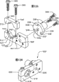
图12是连接于该输送系统的手柄组件的透视图;Figure 12 is a perspective view of a handle assembly coupled to the delivery system;
图13A和13B分别是手柄组件的远端板组件的分解图和透视图;13A and 13B are exploded and perspective views, respectively, of the distal plate assembly of the handle assembly;
图14A和14B分别是手柄组件的近端板组件的分解图和透视图;14A and 14B are exploded and perspective views, respectively, of the proximal plate assembly of the handle assembly;
图15是手柄组件的丝杠的侧视图;Figure 15 is a side view of the lead screw of the handle assembly;
图16是包括测力传感器(load cell)的手柄组件的一个实施例的透视图;Figure 16 is a perspective view of one embodiment of a handle assembly including a load cell;
图17是包括测力传感器的手柄组件的另一个实施例的透视图;Figure 17 is a perspective view of another embodiment of a handle assembly including a load cell;
图18是手柄组件的又一个实施例的透视图;Figure 18 is a perspective view of yet another embodiment of a handle assembly;
图19是输送系统的侧视图,其中该输送系统的近端套筒和远端部分以截面示出;19 is a side view of a delivery system with the proximal sleeve and distal portion of the delivery system shown in cross-section;
图20是拖把状物延伸部分和对应的人造瓣膜部分的截面图;Figure 20 is a cross-sectional view of a mop extension and corresponding prosthetic valve portion;
图21是图18的可替换手柄组件和该输送系统之间的组件的侧视图;Figure 21 is a side view of components between the replaceable handle assembly of Figure 18 and the delivery system;
图22A和22B分别示出输送系统到达自体瓣膜部位并将患病的自体瓣膜小叶推开;Figures 22A and 22B respectively illustrate the delivery system reaching the native valve site and pushing the diseased native valve leaflets away;
图23A至23E示出在用于输送并展开人造瓣膜的一种优选的使用方法期间该输送系统的远端部分;23A to 23E illustrate the distal portion of the delivery system during a preferred method of use for delivering and deploying a prosthetic valve;
图24是示出机械式吊舱尖端的输送系统的可替换实施例的侧视图。Figure 24 is a side view showing an alternative embodiment of a delivery system for a mechanical pod tip.
具体实施方式Detailed ways
现在参考图1,一种心瓣膜输送系统10通常包括:导丝12和具有沿着远端部分设置的可膨胀的球囊18的球囊导管14。可扩展的人造瓣膜16位于该可膨胀的球囊上。该球囊导管14还包括伸长的球囊轴20和在其近端的支撑件22。球囊导管14的球囊轴20被接纳在瓣膜导管23内。正如将在下面更详细地描述的,该瓣膜导管23构造成用于可释放地与人造瓣膜16接合。瓣膜导管23被接纳在管状输送套管24内,其中球囊18至少部分地从该输送套管24的远端伸出。输送套管24的近端被安装在近端套筒(hub)26上。将在下面更详细地讨论并描述的手柄组件500可以连接于该输送套管24的近端套筒26,以实现人造瓣膜16相对于该输送套管24在控制下的推进。Referring now to FIG. 1 , a heart
参考图2,球囊导管14被更详细地示出。球囊导管14配备有限定导丝腔的导丝轴31。支撑件22沿着该球囊导管的近端设置并且包括主轴32和从该主轴32斜向延伸的流体轴34。停止旋塞35沿着该流体轴34设置。主轴32和流体轴34各自包括通道,并且这些通道彼此连通。诸如在美国专利6,592,544号中公开的Touhy Borst阀36从主轴32的近端朝着近端延伸,并且包括在其近端处的紧固阀37,该美国专利的内容作为参考被完全并入本文。所示的球囊轴20大体为管形并且包括外表面38。Referring to Figure 2,
在一个优选结构中,该球囊导管14被装配,以使该球囊轴20的外表面38固定于该支撑件22的主轴32的内表面。该Touhy Borst阀36被设置在该主轴32的近端上并且在两个部件之间用螺纹连接与其固定。在该Touhy Borst阀36内部的压缩阀围绕导丝轴31,并且当该紧固阀37被拧紧时,该压缩阀密封该支撑件22的主轴32中的内部通道,使其与空气隔离。In a preferred configuration, the
参考图3A和3B,可膨胀的球囊18具有近端部分40和远端部分42,并且包括内表面44、外表面46和通过其纵向地延伸的通道48。当从近端部分40向远端部分42观察时,所示球囊18的实施例包括七个区域:第一细长区域50、第一圆锥形区域52、主圆柱形区域54、第二圆锥形区域56、辅助圆柱形区域58、第三圆柱形区域60以及第二细长区域62。该球囊18优选用诸如盐水的流体来膨胀,并且可以用任何合适的材料形成,例如尼龙。球囊18的远端部分42的形状被优选成形,以在导丝12和相对大的直径的输送套管24之间提供过渡构件(如图1所示),因而利于该输送系统前进通过患者的脉管系统。在优选实施例中,球囊18还提供扩张器尖端,因而不需要单独的扩张器机构。球囊的外表面和输送套管优选配备有光滑的涂层。球囊的光滑的涂层和形状使输送系统(包括人造瓣膜)能够前进通过患者体内相对窄的和/或钙化的脉管系统。因此,在一种有利的特征中,可以使用该输送系统的优选实施例而不需要引导套/引导鞘(guide sheath)。Referring to FIGS. 3A and 3B ,
通过参考图1至图3B来更加详细地描述球囊18的一种优选的结构。球囊18的第一细长部分50的内壁44在球囊轴的远端固定于球囊轴20的外表面38,因此将球囊轴20的通道设置为与球囊18的通道48连通。第二细长部分62的内壁44固定于导丝轴31的外表面64。这种连接可以通过粘合或热连接,或者这两者来实现。通道70延伸通过柔软尖端68其中,该柔软尖端68在导丝轴31的远端固定于导丝轴31的外表面64,并且从导丝轴31向远端延伸,并且该柔软末端68的通道70与导丝轴31的通道71相连通。A preferred configuration of
通过参考图4至图8来更加详细地描述瓣膜导管23的组件和功能。如图4所最佳示出的,该瓣膜导管23提供用于固定和释放人造瓣膜16的可释放的接合机构。在所示的实施例中,瓣膜导管23包括多腔轴72,围绕该多腔轴的近端部分设置加劲管(stiffener tube)74。套爪(collet)76从多腔轴72的中心腔的内部延伸,并且被卡接在圆盘(puck)78中。该圆盘78被卡接在拖把状物(mop)80中,使得该拖把状物从该圆盘朝远端/远端地延伸。瓣膜导管23还包括从多腔轴72的近端朝近端/近端地延伸的金属丝管82。正如在下面所描述的,瓣膜导管23将人造瓣膜16输送到自体瓣膜部位并且有助于人造瓣膜16的展开。The components and function of the
参考图5的截面图,多腔轴72的形状优选地成形为圆柱形,并且包括通过其中纵向延伸的中心腔84。六个侧腔86从该多腔轴72的近端向远端延伸。在一个实施例中,多腔轴由诸如聚醚嵌段酰胺,就是通常所说的
参考图6A和6B,套爪76通常是圆柱形形状的并且包括近端90和远端92。中心通道94延伸通过该套爪。靠近近端90,开口96从该套爪76的外表面98向内表面100延伸。四个纵向狭槽102沿着该套爪76的远端92从外表面98通到内表面100,因而形成四个柔性臂104。狭槽102优选从远端92到近端90在宽度上变窄。在套爪76的远端92处,外表面优选地形成成角度的表面106,以有助于与圆盘78的接合。环形形状的凸缘108被设置在近端邻接于该成角度的表面106。沿着套爪76的圆周,外表面98包括凸肩表面109,其垂直于外表面98延伸并且面向该套爪76的远端92。Referring to FIGS. 6A and 6B ,
参考图7A和7B,圆盘78通常为管形形状,并且具有从近端114向远端116纵向地延伸通过该圆盘的中心腔112。该中心腔112由该圆盘78的内表面118限定。该圆盘78的外表面120靠近近端114包括成角度的部分122。环形槽123邻近成角度的部分122,围绕该圆盘78的外表面向远端延伸。靠近远端116,外表面120包括围绕该圆盘78的圆周延伸的卡接脊(snap ridge)124。该卡接脊124被从外表面120延伸的四个圆形凹槽(indentation)125中断。外表面还包括向外延伸的环形形状的凸缘126,其限定凸肩表面130。六个侧腔136从该圆盘78的外表面120的成角度的部分122向圆盘78的远端116平行于中心腔112延伸。这些侧腔136围绕圆盘78的圆周等距离间隔开。圆柱形形状的开口138从该圆盘78的外表面120向内表面118径向地延伸。销子139被插入该开口138中,与外表面齐平并且从圆盘78的内表面118向内伸出。Referring to FIGS. 7A and 7B , the
参考图8,拖把状物80通常为圆柱形形状,并且包括近端140、外表面142、内表面144和延伸通过该拖把状物的通道145。该拖把状物80优选包括六个伸长的延伸部分150,这些延伸部分被构造成用于与人造瓣膜接合。在一个优选实施例中,延伸部分150具有变化的长度,这些变化的长度被构造成用于接合人造瓣膜的不同的部分。每个延伸部分优选地包括靠近远端156的第一开口152和第二开口154。靠近拖把状物80的近端140,四个开口146从外表面142向内表面144延伸,并且沿着拖把状物80的圆周对齐。四个狭槽148从近端140沿着拖把状物80的长度延伸,从外表面142通向内表面144,并且在开口146之间通过。该拖把状物80优选由诸如镍钛(Nitinol)的形状记忆材料,或任何其他合适的材料制造。Referring to FIG. 8, mop 80 is generally cylindrical in shape and includes a
继续参考图4至图8,在组装瓣膜导管23时,圆盘78被卡接在拖把状物80的近端140中。当圆盘的远端116被插入拖把状物80的通道145中时,狭槽148使拖把状物80的近端140能够弯曲(见图7A和图8)。圆盘78的卡接脊124进入拖把状物80的开口146中,并且圆盘78的狭槽凹槽125与拖把状物80的开口146之间的区域对齐。拖把状物80的近端140邻接圆盘78的凸肩表面130。弹簧夹头76卡接在圆盘78中。更具体地说,套爪76的远端92穿过圆盘78的近端114。套爪76的臂状物104弯曲,以穿过圆盘78的中心腔112。圆盘78的伸出部分138穿过套爪76的狭槽102中的一个,并且当狭槽102变窄时被压紧。一旦卡接之后,套爪76的凸缘108支承圆盘78的远端116,并且套爪76的凸肩表面109支承圆盘78的近端114。With continued reference to FIGS. 4-8 , the
多腔轴72设置在圆盘78上的近端。包括开口96的套爪76的近端90被插入该多腔轴72的中心腔84中,使得该多腔轴72的侧腔86与圆盘的侧腔136对齐,套爪76的开口可以用粘性材料填充,以便确保牢固结合。该多腔轴72和套爪76之间的连接可以通过热接合或粘着接合,或者这两者实现。加劲管74靠近其近端设置在多腔轴72上。该加劲管74在该多腔轴72的一部分上延伸。金属丝管82结合在该多腔轴72的近端并且从其斜向延伸。The
参考图9和图10,输送套管24优选包括近端160、远端162、外表面164、内表面166以及纵向延伸通过该输送套管的通道168。该输送套管24包括主要部分170和尖端部分172。正如在下面所讨论的,在前进通过患者的脉管系统到自体瓣膜部位时该输送套管24包含并保护人造瓣膜。该输送套管24的主要部分170包括内层173,设置在该内层上的中间层174,设置在该中间层上的外层176。该输送套管24的主要部分170的内层173优选用诸如特富龙

该输送套管24优选通过挤压工艺形成。在挤压工艺过程中这些金属丝起初被放置在该输送套管24的中间层和外层之间。然后该输送套管24通过加热使中间层和外层流动而被层压(laminate)。层压加工的热量软化中间层174和外层176,使金属丝178埋入输送套管24的中间层和外层中,如图10所示。当在层压加工的过程中加热时,优选用特富龙
在一个优选结构中,金属丝178的一半沿着与金属丝178另一半相反的方向沿着输送套管24的长度成螺旋形,因此,金属丝178彼此交叉形成网状。该金属丝178还彼此在其上和其下通过以形成织物或编织物。金属丝178在输送套管24的主要部分170中从输送套管24的近端160向远端162延伸。输送套管24的尖端部分172不包含设置在该输送套管24的主要部分170中的金属丝105,以确保适当的刚度和可推动性。In a preferred configuration, one half of the
输送套管12的尖端部分172优选由诸如
在该输送套管的主要部分170和尖端部分172之间的过渡部分,不透射线带182被设置在该输送套管24的不锈钢金属丝178和外层176之间。在上述加热层压加工过程中,不透射线带182不流动。在层压完成之后,该不透射线带182围绕金属丝178的端部保持,并且因此用作外层176和金属丝178之间的屏障。该不透射线带182可以包括任何合适的材料,但是优选用包括90%的铂和10%的铱的合金(PLIR)制造。At the transition between the main portion 170 and the
现在参考图11,图11提供沿着该输送套管24的近端套筒26的截面图。该近端套筒26优选包括圆柱形形状的套筒主体200,该套筒主体200具有纵向延伸通过该套筒主体的通道201。套筒主体200部分地由设置在该套筒主体200远端的壳体202围绕。延伸进入该套筒主体200的通道201中的具有开口204的端件203被安装在套筒主体200的近端并且从其伸出。当从近端向远端观察时,该端件203的外表面包括锥形表面205A、第一瓶颈表面205B、面向远端的第一凸肩表面205C、第二瓶颈表面205D和面向近端的第二凸肩表面205E。该第一凸肩表面205C、第二瓶颈表面205D和第二凸肩表面205E限定围绕该端件203延伸的槽206。Referring now to FIG. 11 , FIG. 11 provides a cross-sectional view along the
近侧地邻近该端件203并在该套筒主体200内部,设置十字形阀207,并且该十字形阀被隔离物(spacer)208部分地围绕,近侧地邻近该十字形阀206和该隔离物208并且在该套筒主体200内部,设置圆盘阀210。鸭嘴形阀212也被设置在套筒主体200内部,其近侧邻近该圆盘阀210。止血开口212从通道201延伸,并且止血管214从套筒主体200向三路停止旋塞216延伸。近端套筒的一个优选实施例详细地描述在名称为“血管内的输送系统(ENDOVASCULAR DELIVERYSYSTEM)”的美国专利5,968,068号中,其内容通过参考全部并入本文。Proximally adjacent to the
继续参考图11,该输送套管24固定于该近端套筒26。该输送套管24的近端160在其远端被插入该近端套筒26的通道201中。输送套管24的外表面164通过粘着接合或热接合固定于近端套筒26的壳体202的内表面,因此,以将近端套筒的通道201设置为与该输送套管24的通道168相连通。Continuing to refer to FIG. 11 , the
通过参考图12至图15来描述手柄组件500的一个优选实施例。图解说明的手柄组件500提供机械致动机构,用于以可控和精确的方式从该输送套管24的远端推进人造瓣膜。该手柄组件500通常包括远端板组件502,其连接于在该输送套管24的近端上的近端套筒26。该手柄组件还包括近端板组件504,其连接于瓣膜导管23。丝杠506穿过该远端板组件502和近端板组件504。A preferred embodiment of a
具体参考图13A和13B,该远端板组件502包括主要部分510、上部512和丝杠螺母514。该主要部分510和上部512组合,以包括从该远端板组件502的近侧面518通到远侧面520的第一开口516。该第一开口516由近侧开口表面522、远侧开口表面524和凸肩表面525限定。该近侧开口表面522和远侧开口表面524从该远端板组件502的近侧面518和远侧面520垂直地延伸。该凸肩表面525面向近侧,并且在该远端板组件502的近侧开口表面522和远侧开口表面524之间基本上平行于远端板组件502的近侧面518和远侧面520延伸。在该远端板组件502中的第二开口526从近侧面518向远侧面520延伸。同样延伸通过该远端板组件502的紧固件开口527被设置在第二开口526的区域中。Referring specifically to FIGS. 13A and 13B , the
丝杠螺母514为管形形状,具有外表面528、内表面530和纵向延伸通过该丝杠螺母的开口532。向外延伸的凸缘534邻近该丝杠螺母514的近端536向外延伸。紧固件开口538通过该凸缘534到该丝杠螺母514的近端536。该丝杠螺母514的内表面530是螺纹的。The
该远端板组件502的上部512用远端板组件紧固件540固定于该远端板组件502的主要部分510,该远端板组件紧固件540啮合远端板组件紧固件孔542。该远端板组件紧固件孔542通过该远端板组件502的上部512并进入该远端板组件502的主要部分510中。The
当该丝杠螺母514的近端536放置在该主要部分510的远侧面520上时,该丝杠螺母514固定于该远端板组件502的主要部分510,并且该主要部分510的紧固件开口527与丝杠螺母514的紧固件开口538对齐。丝杠螺母514中的开口532与远端板组件502的第二开口526对齐。丝杠螺母紧固件544啮合紧固件开口527和538,并且将该丝杠螺母514固定于该远端板组件502的主要部分510。When the
参考图14A和14B,近端板组件504包括主要部分546、盖部分548和从该主要部分546延伸的手柄550。该主要部分546和盖部分548组合以形成从近侧面554通过到远侧面556的中心开口552。该中心开口552由近侧开口表面558、远侧开口表面560和内腔表面562限定。该近侧开口表面558和远侧开口表面560从该近端板组件504的近侧面554和远侧面556垂直地延伸。该内腔表面562在近侧开口表面558和远侧开口表面560之间延伸,并且在组装的近端板组件504内形成开口的内腔。Referring to FIGS. 14A and 14B , the
在近端板组件504中的第一侧开口564从该近侧面554向远侧面556延伸。该手柄550固定于该近端板组件504的主要部分546,使得它通过该第一侧开口564并且用定位螺钉565固定。在近端板组件504中的第二侧开口566也从该近侧面554向远侧面556延伸。该近端板组件504的盖部分548用近端板组件紧固件568固定于该近端板组件504的主要部分546,该近端板组件紧固件568啮合近端板组件紧固件孔570。该近端板组件紧固件孔570通过该近端板组件504的盖部分548并进入该近端板组件504的主要部分546。A
参考图15,该丝杠506包括在其近端的旋转器旋钮572、无螺纹部分574和邻近其远端的螺纹部分576。该旋转器旋钮572包括从其朝着远端延伸的颈部578,并且该无螺纹部分574从该颈部朝着远端延伸。在该旋转器旋钮572的颈部578的远端处的凸肩表面580面向远端。槽581围绕该丝杠506的圆周延伸。Referring to FIG. 15, the
参考图12至图15,当丝杠506被放置为通过该近端板组件504的第二侧开口566和丝杠螺母开口532以及远端板组件502的第二侧开口526,使得旋转器旋钮572的凸肩表面580邻靠该近端板组件504的近侧面554时,该手柄组件500被组装。卡接环582被设置在该丝杠506的无螺纹部分574上的槽581中,使得它邻靠该近端板组件504的远侧面556。该远侧面556上的卡接环582和该近侧面554上的凸肩表面580防止该丝杠514通过该近端板组件504的第二侧开口556的平移,该丝杠506在该近端板组件504的第二侧开口556中旋转。丝杠506的螺纹部分576啮合该丝杠螺母514的带螺纹的内表面530。Referring to FIGS. 12-15 , when the
参考图16,图16示出该手柄组件500的可替换实施例,其中该丝杠螺母514从该远端板组件502近侧地设置。中间板590围绕该丝杠螺母514,并且丝杠螺母紧固件544将该中间板590固定于该丝杠螺母514。该中间板590固定于测力传感器(load cell)592,该测力传感器固定于远端板组件502。如图16所示的测力传感器592在本领域是公知的,并且可以以本领域公知的方式连接于测量该测力传感器592的位移的装置(未示出)。该装置将测力传感器592的位移转换成被作用的力,该力相对于该中间板590移动该远端板组件502。Referring to FIG. 16 , an alternative embodiment of the
参考图17,该手柄组件500的另一个可替换实施例包括朝着手柄550延伸的该中间板590的分叉的部分594,该手柄通过该分叉的部分594的开口596。第二手柄598通过该远端板组件502,并且由第二定位螺钉600固定,该第二定位螺钉600通过该远端板组件502与该第二手柄598接触。在该远端板组件502中的手柄开口602使固定于该近端板组件504上的手柄550能够毫无阻挡地通过该远端板组件502。Referring to FIG. 17 , another alternative embodiment of the
参考图18,图18图示说明另一种可替换的手柄组件608,其中不需要该近端板组件和远端板组件。中空的轴610包括与其平行延伸的卡接件612。该卡接件612由在该轴610和该卡接件612之间延伸的桥接件614连接于该轴610。在远端,该卡接件612包括朝着该轴610向里延伸的凸缘616,形成面向近侧的表面618。具有内螺纹表面的展开旋钮620可旋转地连接于该轴610。Reference is made to Figure 18, which illustrates an
现在参考图19来更详细地描述该输送系统10的功能性。球囊导管14被构造成用于插入瓣膜导管23中。球囊轴20被设置在多腔轴72的中心腔84中,并且球囊轴20的外表面38,例如通过粘着固定于该多腔轴72的内表面。该球囊轴20从近端地位于该多腔轴72的近端的支撑件22延伸,通过该多腔轴72的中心腔84,通过该套爪76的通道94,通过该圆盘78的中心腔112,到达拖把状物80的通道145。该球囊18的主要圆柱形部分54从该拖把状物80的远端156朝着远端延伸。人造瓣膜16卷缩成足够小以进入该输送套管24的通道168。人造瓣膜16由该球囊18的主要圆柱形部分54支撑并且被放置在该输送套管24的尖端部分172的区域中的内表面166上,该人在瓣膜被包含在其中并且循迹行进到自体瓣膜部位。The functionality of the
该输送系统10优选地被构造成与自扩展的人造瓣膜16一起使用。在一个优选实施例中,人造瓣膜至少部分地由诸如镍钛(Nitinol)的记忆材料形成,其中该人造瓣膜采用在预定温度下的刚性形状,但是在较低的温度下是比较有延展性的。这种自扩展的人造瓣膜的示例详细地描述在2004年9月23日公布的美国专利公开第2004/0186563 A1号中,其内容通过参考完全并入本文,但是应当理解,本发明的许多特征也可以与其他类型的人造瓣膜一起使用,诸如,例如球囊可扩展的瓣膜。优选的球囊可扩展的人造瓣膜的示例公开在名称为“可植入的人造瓣膜(Implantable Prosthetic Valve)”的美国专利6,730,118号和名称为“可植入的人造瓣膜(Implantable Prosthetic Valve)”的美国专利6,893,460号中,两者的内容通过参考结合于此。The
继续参考图19,输送套管24和近端套筒26被设置在瓣膜导管23上。该瓣膜导管23通过该端件203的开口204、近端套筒26(包括阀207、210和212)的通道201和输送套管24的通道168(见图11)。近端套筒26被设置在瓣膜导管23的近端附近,其中加劲管74进入近端套筒26的通道201(见图11)并且从其朝着远端延伸。人造瓣膜16被设置在该输送套管24的远端162附近的通道168中(见图11)。当经受比体温低的温度时,自扩展的人造瓣膜16能够卷缩以便安装在输送装置里面。球囊18从该输送套管24的远端162朝着远端伸出。With continued reference to FIG. 19 ,
导丝12被插入导丝轴31的通道71中。该导丝12从该导丝轴31的远端和柔软的尖端68朝着远端延伸,并且从该导丝轴31的近端朝着近端延伸。
成束的金属丝234延伸通过该金属丝管82。该成束的金属丝形成优选的致动机构的一部分,用于从瓣膜导管释放人造瓣膜到治疗部位处。该成束的金属丝234由六根单个的金属丝构成,这些单个的金属丝在金属丝管82的末端离开该金属丝管82,并进入该多腔轴72的六个侧腔86。旋钮236位于该成束的金属丝234的近端上。该成束的金属丝234的六根单个的金属丝离开该多腔轴的远端,并进入该圆盘78的侧腔136中(见图7A和7B)。该成束金属丝234的六根单个的金属丝在该圆盘78的远端116离开该侧腔136并朝着该拖把状物80的远端156延伸。A bundle of
热收缩器(heat shrink)237能够用于增强该多腔轴72、金属丝管82和球囊导管14之间的连接。该热收缩器237被设置在该金属丝管82、多腔轴72和该支撑件22的主轴32上,并且被热处理直到它围绕这些部件形成变硬的外壳,从而将它们相互固定并且使该输送系统10更加牢固。A heat shrink 237 can be used to enhance the connection between the
现在参考图20来描述一种用于将该人造瓣膜16可释放地连接到瓣膜导管的优选装置。一般地说,人造瓣膜16优选由提供系绳(tether)和勒除(snare)机构的可弯曲伸长件连接于瓣膜导管的拖把状物80部分(见图8)。为了实现这一目的,一个或多个缝合线(suture)238(系绳)通过部分人造瓣膜并且通过该瓣膜导管的拖把状物80部分。该缝合线238优选地包括延伸通过部分人造瓣膜的圈。(一个或多个)可滑动的金属丝234延伸通过该圈以防止该缝合线从人造瓣膜脱开。因此,可滑动的金属丝234提供可释放的勒除机构,该勒除机构能够被抽出用于快速地并容易地从该人造瓣膜脱开该缝合线。Referring now to FIG. 20, a preferred arrangement for releasably connecting the
在图20所示的优选实施例中,人造瓣膜16的近端部分被设置在该拖把状物80的内表面144的第二开口154附近。金属丝234的六根单个的金属丝从该圆盘78的侧腔136延伸(见图7A)并且压靠在该拖把状物80的延伸部分的150的内表面144上。该单个的金属丝沿着该人造瓣膜16的侧面通过,其中该人造瓣膜16被设置在拖把状物80的内表面144和该单个的金属丝之间。这些单个金属丝的远端能够被藏进/包进该人造瓣膜16的合缝袋中(commissure pocket)或者在该人造瓣膜16的合缝柱(post)处的小叶之间,以避免暴露于该输送套管24,同时在展开时循迹行进在且循迹行进到人体脉管。In the preferred embodiment shown in FIG. 20 , the proximal portion of the
诸如由缝合线或其他材料形成的环的锚定物优选被提供在圆盘78的环形槽123中(见图7A)。该缝合线238系于该锚定物中,并且然后沿着拖把状物80(见图8)的外表面142从该锚定物通过。在那上面缝合线通过该拖把状物80的延伸部分150其中之一的第一开口152,环绕金属丝234的单个金属丝,并通过第一开口152返回到拖把状物80的外表面142。然后缝合线238通过该拖把状物80的延伸部分150其中之一的第二开口154,通过人造瓣膜16的连接开口239,围绕该单个的金属丝234,通过人造瓣膜16的连接点返回,并且通过拖把状物80的同一个延伸部分150的第二开口154返回到拖把状物80的外表面142。该缝合线238系在圆盘78的环形槽123处的锚定物中,使得它形成从该锚定物延伸到拖把状物80(见图8)的延伸部分150的远端156的缝合线圈。该缝合线238用于形成对应于该拖把状物80的每个延伸部分150的类似的缝合线圈,其中系绳和勒除机构被形成在拖把状物80的每个延伸部分150的远端156附近。缝合线238绕其自身缠绕,并且在沿着每个延伸部分150的外表面142通过之前系在与拖把状物的每个延伸部分150对齐的位置,以形成缝合线圈。An anchor such as a loop formed of suture or other material is preferably provided in an annular groove 123 of the disc 78 (see FIG. 7A ). The
再参考图12至图18,来更加详细地描述手柄组件500与输送系统10的连接。近端板组件504抓牢插入该近端板组件504的中心开口552中的瓣膜导管23。瓣膜导管23的加劲管74(见图4)接触该近端板组件504的近侧开口表面558和远侧开口表面560(见图14A)。该接触足够紧,以至于能够将该瓣膜导管23固定于近端板组件504。Referring again to FIGS. 12-18 , the connection of the
远端板组件502被固定于近端套筒26上。端件203通过该远端板组件502的第一开口516(见图13B),其中该远端板组件502接合该端件203的槽506(见图11)。该端件203的第一瓶颈表面205B(见图11)靠在远端板组件502的近端开口表面522上(见图13A和13B)。端件203的第一凸肩表面205C(见图11)靠在远端板组件502的凸肩表面525上(见图13A和13B)。端件203的第二瓶颈表面205D(见图11)靠在远端板组件502的远侧开口表面524上(见图13A和13B)。端件203的第二凸肩表面205E靠在远端板组件502的远侧面520上(见图13A和13B)。The
图16和图17所示的实施例很适合于使操作者能够知道当人造瓣膜16离开输送套管24时作用在人造瓣膜16上的力,这将在下面描述。由于延伸的远端板组件502和第二手柄598使绕由瓣膜导管23限定的轴线的重量的均匀分布,图17所示的实施例适合于稳定手柄组件500。分叉的部分594除了用作绕由瓣膜导管23限定的轴线均匀地分布重量的装置之外,还用于防止在瓣膜展开和丝杠506操作时该装置在应力作用下的旋转,这将在下面描述。The embodiment shown in Figures 16 and 17 is well suited to enable the operator to know the forces acting on the
在图18所示的可替换实施例中,通过将轴610卡接在近端套筒26中(见图11)中,手柄组件608被连接于输送系统10,如图21所示。该轴610进入端件203的开口204中(见图11)。卡接件612的凸缘616在锥形表面205A和第一瓶颈表面205B上通过,以接合端件203的槽206(见图11)。卡接件612的面向近侧的表面618靠在近端套筒26的端件203的第一凸肩表面205C上。展开旋钮的内螺纹表面啮合瓣膜导管23的螺纹表面622。瓣膜导管23的螺纹表面622可以包含在加劲管74中(见图4)。In an alternative embodiment shown in FIG. 18, the
现在参考图1至图11,来更加详细地描述利用该输送系统10输送人造瓣膜16的优选方法。按照现有技术公知的方法,首先将导丝12插入人体脉管中,例如股动脉。该导丝12通过病人的动脉,并且通过自体瓣膜的开口。如果希望,可以将扩张器插入该导丝12上进入体腔。一种优选的扩张器详细描述在名称为“血管内的输送系统(EndovascularDelivery System)”的5,968,068号美国专利中,其内容通过参考全部结合于此。该扩张器用来增大人体脉管的开口,因而便于使该输送系统10进入人体脉管内。在脉管扩张并且输送系统10进入人体脉管之后,该扩张器被取出。但是,正如上面所讨论的,由于球囊和输送套管的形状和涂层,不用扩张器也可以使用该输送系统的实施例。Referring now to FIGS. 1-11 , the preferred method of delivering the
输送系统10在导丝12上循迹行进并且进入人体脉管中。亲水涂层优选用于在球囊18(见图3A)的外表面46和输送套管24(见图11)的外表面164上提供光滑性。光滑的表面通过减少与人体脉管壁之间的摩擦力的量,使装置容易进入并且容易推动该装置到自体瓣膜部位,其中该装置通过该人体脉管壁循迹行进。该球囊18的第二圆锥部分56的外表面46(见图3A和3B)提供锥形表面,以便容易进入人体脉管中。在输送套管24的远端162处,该输送套管24的尖端部分172的锥形表面180(见图9)也便于进入该人体脉管中。The
现在参考图22A,当输送系统10向自体瓣膜部位250循迹行进时,其在导丝12上通过。当操作者以逆行(即与血流反向)的过程推动该输送系统10通过该股动脉,越过主动脉弓254并到达自体瓣膜部位250时发生循迹行进。循迹行进时球囊18用于充当人体脉管内的扩张器。人体脉管由于其大小和钙化作用可能是收缩的。球囊18提供锥形的柔软的表面,用于当输送系统10的远端通过人体脉管前进时,逐渐扩张人体脉管的狭窄的区域。如果需要,该球囊可以部分地或整个地缩小,并且然后在前进时重新膨胀,以进一步便于前进通过狭窄的脉管系统。输送套管24的结构赋予它足够的柔软性和可推进性,以循迹行进到自体瓣膜部位250。透视法使操作者知道输送系统10的位置,其中可以看见输送套管24的不透射线带182(见图9)相对于该自体瓣膜部位250的位置。Referring now to FIG. 22A , the
在输送系统10向自体瓣膜部位循迹行进的过程中,该输送套管24弯曲以便通过人体脉管的弯曲部分,包括在主动脉弓254中存在的弯曲部分。输送套管24的弯曲可以使瓣膜导管23的部件相对于该输送套管24的内表面166(见图9)移动。该弯曲还可以使该输送套管24的通道变窄,因而增加摩擦。因此,输送套管24的优选实施例具有用诸如
在向自体瓣膜部位250循迹行进时由于输送套管24弯曲,因此弯曲力被施加在金属丝178上(见图10)。作用在金属丝178上的力使金属丝178压在该输送套管24的中间层174和外层176上。因此,不透射线带182(见图9)优选地由具有足够的抗穿刺性的材料制造,使得当该套管24弯曲时由该金属丝178的端部作用的力不能刺穿该输送套管24的外层176。输送套管24的内层173(见图10)也对瓣膜导管23和球囊导管14提供保护免受金属丝178的损害。被选用为该内层173的材料在上面所述的加热层压处理中不流动。金属丝178不会嵌进该内层173中。因此内层173在金属丝178和输送套管24的通道168之间提供屏障。As the
参考图22B,一旦输送系统10已经到达瓣膜部位,操作者能够将人造瓣膜16(见图1)推过自体瓣膜小叶256,从而解除已经变得狭窄的小叶256。主动脉狭窄是心脏的主动脉瓣的疾病。狭窄的小叶变厚、变硬并且钙化;它们的运动比健康的小叶受更多的限制。变窄的小叶阻碍血液流动,只留下很小的孔使血液能够注入主动脉。瓣膜移植可能要求小叶被去掉或被推向旁边。但是,狭窄的小叶的变硬的性质使解除过程变复杂。Referring to FIG. 22B , once the
膨胀时球囊18能够变硬并且能够用于扩张自体心瓣膜的变窄的小叶。球囊18被缩小并且球囊18的第二圆锥形部分56通过该变窄的小叶之间的小孔。然后球囊18重新膨胀,如图22B所示,并且扩展的球囊对狭窄的小叶的变硬的组织施加足够的压力,以扩张小叶。这种扩张有助于人造瓣膜16的展开(见图19),这将在下面进行描述。
在瓣膜展开的优选方法中,当瓣膜导管23保持固定时该输送套管24被缩回,将人造瓣膜16暴露在移植部位而不需要人造瓣膜在暴露于体腔时循迹行进通过体腔。而且,在引入人体脉管并且循迹行进通过人体脉管时,由于瓣膜相对于输送套管24保持静止,因此不需要使瓣膜通过导向或引进套。In the preferred method of valve deployment, the
在图12、16和17所示的实施例中,其中采用手柄组件500,操作者转动旋转器旋钮572以缩回输送套管并且因而将人造瓣膜暴露在人体脉管并且完成展开。丝杠506的螺纹部分576的螺纹作用在丝杠螺母514的内螺纹上,使丝杠螺母514和远端板组件502朝着近端板组件504平移,该近端板组件504相对于丝杠506由卡接环582保持平移中的静止。因此,该远端板组件502和近端板组件504相对于彼此移动,这使在近端套筒26的端件203处连接于该远端板组件502的输送套管24和固定于近端板组件504的瓣膜导管23相对于彼此移动。In the embodiment shown in Figures 12, 16 and 17, where
在图18和图21所示的采用可替换手柄组件608的可替换实施例中,操作者转动展开旋钮620,使得旋钮620、以及连接于该展开旋钮620的近端套筒26和输送套管24在瓣膜导管23上朝着近端移动。In an alternative embodiment using an
丝杠506或可替换手柄组件608的使用潜在地减少从人造瓣膜16缩回该输送套管所需要的力。该丝杠506旋转一周使丝杠螺母514在该丝杠506的螺纹部分576上前进单个螺纹之间的距离。称之为螺距的螺纹之间的距离确定操作者致动该旋转器旋钮572所需要的力的量。螺距越小,该旋转器旋钮572每旋转一圈实现的平移运动越小。一方面该输送套管24的相对平移运动越小,另一方面人造瓣膜和瓣膜导管19的相对平移运动越小,该系统的操作者需要的力越小。在本发明的优选实施例中,该丝杠具有1/4英寸的螺距。The use of
在不采用丝杠的本发明的可替换实施例中,操作者使瓣膜导管23在近端套筒26上保持稳定并且拉回(朝近端),该瓣膜导管留在人体脉管外面,以将人造瓣膜暴露在人体脉管内并且完成瓣膜的展开。In an alternative embodiment of the invention that does not employ a lead screw, the operator stabilizes and pulls back (proximally) the
参考图23A,所示的输送套管24在缩回位置,因此人造瓣膜16和拖把状物80的延伸部分150被露出。尽管存在由扩展的人造瓣膜施加在该输送套管24上的压力,但是输送套管24的尖端部分172足够柔软以在瓣膜展开时能够拉回输送套管24。为了使缩回输送套管24更加容易由操作者执行,该输送套管24的内层173(见图9)可以用诸如
参考图23B,在人造瓣膜16的自扩展能力使其向外扩展时球囊18可以缩小。拖把状物80的延伸部分15优选足够柔软,因此在保持与瓣膜16的连接的同时该延伸部分允许瓣膜的扩展。参考图23C,在人造瓣膜16已经开始扩展之后,该球囊18可以再一次膨胀以进一步增大人造瓣膜16的直径。该附加的扩展确保人造瓣膜呈现完全扩展的状态,由此该瓣膜被牢固地安放在自体瓣膜的部位250。在人造瓣膜扩展时在自体瓣膜部位250的小叶256压靠在主动脉的壁上。正如上面所讨论的,球囊18由连接于该球囊导管14的支撑件22的流体轴34的流体源来膨胀(见图2)。停止旋塞35控制流进主轴32和球囊导管14的球囊轴20中的流体的流量(见图2)。Touhy Borst阀36的压缩阀防止流体从球囊导管14(见图2)泄漏。Referring to Figure 23B, the
拖把状物80的延伸部分150向外弯曲,以容纳人造瓣膜16的扩展。如图23B和23C所示在人造瓣膜16膨胀时,通过推进或拉回该输送系统10的瓣膜导管23,操作者可以调节人造瓣膜的位置。拖把状物80的延伸部分150具有足够的刚度以使人造瓣膜16的位置能够用最小的控制量被操纵。在瓣膜扩展之前,瓣膜定位的控制由操作者推、拉或扭转该瓣膜导管23来实现。瓣膜导管23和球囊导管14之间的连接使该瓣膜导管23的移动能够从该瓣膜导管23传递给球囊导管14。
参考图23D,应当理解,在瓣膜展开期间,瓣膜导管23和输送套管24之间的相对运动能够通过反转旋转器旋钮572(或展开旋钮620)的方向,或通过在保持内导管23固定的同时手工推动(朝远端)近端套筒26而被反向。在一个有利的特征中,在瓣膜初始展开之后如果瓣膜的位置和/或方位不是所希望的,则输送套管可以相对于瓣膜导管移动(即,前进)以减小瓣膜的直径。更具体地说,当输送套管24的远端162在拖把状物80的延伸部分150上朝远端前进时,该延伸部分150被向里推。由于该延伸部分被向里推,人造瓣膜被皱缩。因此,如果操作者不满意人造瓣膜16的初始展开,则操作者可以皱缩并且重新定向该人造瓣膜16。结果,输送系统可以用来部分地或整个地将人造瓣膜拉回到该输送套管中使得人造瓣膜能够重新展开或完全缩回。Referring to FIG. 23D , it will be appreciated that during valve deployment, relative movement between
参考图23E,一旦操作者对人造瓣膜16的安放位置满意之后,该人造瓣膜从拖把状物80的延伸部分150分开。为了从瓣膜导管23脱开人造瓣膜16,拉动连接于该结合金属丝234的旋钮236(见图19)。金属丝234的六根单个的金属丝的远端从合缝袋和瓣膜小叶中并且从该缝合线238被拉出,使缝合线238能够离开人造瓣膜16的连接点,因此缝合线238离开人造瓣膜16(见图20)。于是人造瓣膜16与瓣膜导管23脱离。人造瓣膜16的脱离可以在操作者认为合适的任何时候发生,但是通常当延伸部分150已经向外扩展到其最充分的程度时发生。Referring to FIG. 23E , once the operator is satisfied with the placement of the
在释放人造瓣膜16之后,瓣膜导管23和球囊导管14优选地返回到输送套管24的通道168中(见图11)。在包括手柄组件500和608(见图12和图21)的本发明的这些实施例中,为了使瓣膜导管23和球囊导管14返回到输送套管24的通道168中,操作者改变旋转器旋钮572或展开旋钮620的方向。在不采用丝杠的可替换实施例中,在保持输送套管24(见图1)固定的同时,外科医生(朝近端)拉瓣膜导管23和球囊导管14。于是该输送系统10从病人的人体脉管抽回。After the
虽然本文描述的优选实施例包括可以用作扩张器尖端并且可以用于帮助安放该人造瓣膜的球囊导管,但是应当理解,该系统可以没有该球囊导管而使用。当不提供球囊导管时,人造瓣膜从瓣膜导管释放并且用足够的力自扩展,以牢固地将其自身植入在治疗部位。在这里描述的优选实施例的另一种变型中,该输送系统可以被构造成使得球囊导管和瓣膜导管形成整体单元。While the preferred embodiment described herein includes a balloon catheter that can be used as a dilator tip and that can be used to aid in placement of the prosthetic valve, it should be understood that the system can be used without the balloon catheter. When the balloon catheter is not provided, the prosthetic valve is released from the valve catheter and self-expands with sufficient force to firmly implant itself at the treatment site. In another variation of the preferred embodiment described herein, the delivery system may be configured such that the balloon catheter and valve catheter form an integral unit.
参考图24,在另一个可选实施例中,从输送套管24朝远端伸出的过渡件可以采用机械式吊舱(basket)700的形式,以方便进入人体脉管中并向自体瓣膜部位循迹行进。该机械式吊舱包括被包围在尿烷(urethane)罩704中的支杆(strut)702,该罩在远端固定在导丝轴31上并且在近端固定在吊舱轴705上。该支杆702用激光切割管材形成。该支杆能够被热定型以向外弯曲,并且优选由高级弹性镍钛(Nitinol)形成,以便有效地扩展和皱缩。该人造橡胶罩704提供平滑的圆形的尖端,用于循迹行进通过主动脉。在循迹行进时,吊舱700从输送套管24的远端162伸出。Referring to FIG. 24, in another alternative embodiment, the transition piece extending distally from the
吊舱轴705通过球囊轴20。球囊18在远端42(见图3A和3B)处被固定在该吊舱轴705上,并且在近端40(见图3A和3B)处被固定在球囊轴20上。该球囊轴20通过输送套管24。The
导丝轴31从吊舱轴705朝着远端伸出,并且包括拉线706,该拉线从其被连接的位置导丝轴31的远端处延伸通过吊舱到达输送系统10的近端,其中拉线可以被操作以扩展或皱缩该吊舱700。导丝轴31和吊舱轴705通过该输送系统10并且从该支撑件22(见图2)朝近端伸出。该吊舱轴705从导丝轴31朝近端伸出。当操作者使该吊舱轴705保持固定并且推或拉该导丝轴31时,该导丝轴31和吊舱轴705能够相对于彼此移动。操作者还可以使用该拉线706实现该导丝轴31和吊舱轴705之间的相对运动。当吊舱的远端和近端移动彼此离开或靠近时,这两个轴31和705之间在远端的相对运动使吊舱700的支杆702向里或向外弯曲。The
在向自体瓣膜部位循迹行进时,吊舱700从输送套管24的远端162朝着远端伸出。类似于上述的球囊18,吊舱700的形状提供锥形表面,用于容易过渡进入人体脉管中,并且容易循迹行进通过人体脉管到自体瓣膜部位。The
在图24所示的可替换实施例中,该导丝轴31和吊舱轴705之间的相对运动用于皱缩和扩张吊舱700的支杆702。尿烷罩704与支杆702一起皱缩。该机械式吊舱700能够被皱缩和扩张,以解除狭窄的小叶或扩张人体脉管的紧缩部分。正如本文其他实施例所讨论的,人造瓣膜16可以放置被在球囊18上和输送套管24中,并且如本文其他实施例所讨论的,瓣膜展开能够类似地进行。In an alternative embodiment shown in FIG. 24 , the relative motion between the
虽然已经以其优选实施例的形式描述了本发明,但是应当理解,已经使用词语是描述性的词语而不是限制性词语。因此,能够在所附权利要求的范围内进行各种修改,而不脱离本发明的真实范围和精神。While the invention has been described in terms of its preferred embodiments, it is understood that the words which have been used are words of description rather than limitation. Accordingly, various modifications can be made within the scope of the appended claims without departing from the true scope and spirit of the invention.
Claims (9)
Applications Claiming Priority (3)
| Application Number | Priority Date | Filing Date | Title |
|---|---|---|---|
| US11/252,657 | 2005-10-18 | ||
| US11/252,657 US8167932B2 (en) | 2005-10-18 | 2005-10-18 | Heart valve delivery system with valve catheter |
| PCT/US2006/040182 WO2007047488A2 (en) | 2005-10-18 | 2006-10-16 | Heart valve delivery system with valve catheter |
Related Child Applications (1)
| Application Number | Title | Priority Date | Filing Date |
|---|---|---|---|
| CN201110092241.XA Division CN102125471B (en) | 2005-10-18 | 2006-10-16 | Heart valve delivery system with valve catheter |
Publications (2)
| Publication Number | Publication Date |
|---|---|
| CN101291637A CN101291637A (en) | 2008-10-22 |
| CN101291637B true CN101291637B (en) | 2011-06-01 |
Family
ID=37719817
Family Applications (2)
| Application Number | Title | Priority Date | Filing Date |
|---|---|---|---|
| CN2006800389085A Active CN101291637B (en) | 2005-10-18 | 2006-10-16 | Heart valve delivery system with valve catheter |
| CN201110092241.XA Active CN102125471B (en) | 2005-10-18 | 2006-10-16 | Heart valve delivery system with valve catheter |
Family Applications After (1)
| Application Number | Title | Priority Date | Filing Date |
|---|---|---|---|
| CN201110092241.XA Active CN102125471B (en) | 2005-10-18 | 2006-10-16 | Heart valve delivery system with valve catheter |
Country Status (8)
| Country | Link |
|---|---|
| US (6) | US8167932B2 (en) |
| EP (2) | EP2255753B2 (en) |
| JP (1) | JP4989655B2 (en) |
| CN (2) | CN101291637B (en) |
| AT (1) | ATE502604T1 (en) |
| CA (3) | CA3001004C (en) |
| DE (1) | DE602006020906D1 (en) |
| WO (1) | WO2007047488A2 (en) |
Cited By (4)
| Publication number | Priority date | Publication date | Assignee | Title |
|---|---|---|---|---|
| US9034033B2 (en) | 2011-10-19 | 2015-05-19 | Twelve, Inc. | Prosthetic heart valve devices, prosthetic mitral valves and associated systems and methods |
| US9125740B2 (en) | 2011-06-21 | 2015-09-08 | Twelve, Inc. | Prosthetic heart valve devices and associated systems and methods |
| US9421098B2 (en) | 2010-12-23 | 2016-08-23 | Twelve, Inc. | System for mitral valve repair and replacement |
| US9579198B2 (en) | 2012-03-01 | 2017-02-28 | Twelve, Inc. | Hydraulic delivery systems for prosthetic heart valve devices and associated methods |
Families Citing this family (717)
| Publication number | Priority date | Publication date | Assignee | Title |
|---|---|---|---|---|
| US6006134A (en) | 1998-04-30 | 1999-12-21 | Medtronic, Inc. | Method and device for electronically controlling the beating of a heart using venous electrical stimulation of nerve fibers |
| EP0850607A1 (en) | 1996-12-31 | 1998-07-01 | Cordis Corporation | Valve prosthesis for implantation in body channels |
| US6254564B1 (en) | 1998-09-10 | 2001-07-03 | Percardia, Inc. | Left ventricular conduit with blood vessel graft |
| US8016877B2 (en) | 1999-11-17 | 2011-09-13 | Medtronic Corevalve Llc | Prosthetic valve for transluminal delivery |
| US8579966B2 (en) | 1999-11-17 | 2013-11-12 | Medtronic Corevalve Llc | Prosthetic valve for transluminal delivery |
| US7018406B2 (en) | 1999-11-17 | 2006-03-28 | Corevalve Sa | Prosthetic valve for transluminal delivery |
| US8241274B2 (en) | 2000-01-19 | 2012-08-14 | Medtronic, Inc. | Method for guiding a medical device |
| US6692513B2 (en) | 2000-06-30 | 2004-02-17 | Viacor, Inc. | Intravascular filter with debris entrapment mechanism |
| US7749245B2 (en) | 2000-01-27 | 2010-07-06 | Medtronic, Inc. | Cardiac valve procedure methods and devices |
| DE10010074B4 (en) | 2000-02-28 | 2005-04-14 | Fraunhofer-Gesellschaft zur Förderung der angewandten Forschung e.V. | Device for fastening and anchoring heart valve prostheses |
| DE10010073B4 (en) * | 2000-02-28 | 2005-12-22 | Fraunhofer-Gesellschaft zur Förderung der angewandten Forschung e.V. | Anchoring for implantable heart valve prostheses |
| US6454799B1 (en) | 2000-04-06 | 2002-09-24 | Edwards Lifesciences Corporation | Minimally-invasive heart valves and methods of use |
| US6733525B2 (en) | 2001-03-23 | 2004-05-11 | Edwards Lifesciences Corporation | Rolled minimally-invasive heart valves and methods of use |
| US7556646B2 (en) | 2001-09-13 | 2009-07-07 | Edwards Lifesciences Corporation | Methods and apparatuses for deploying minimally-invasive heart valves |
| US7544206B2 (en) | 2001-06-29 | 2009-06-09 | Medtronic, Inc. | Method and apparatus for resecting and replacing an aortic valve |
| US8623077B2 (en) | 2001-06-29 | 2014-01-07 | Medtronic, Inc. | Apparatus for replacing a cardiac valve |
| US8771302B2 (en) | 2001-06-29 | 2014-07-08 | Medtronic, Inc. | Method and apparatus for resecting and replacing an aortic valve |
| FR2826863B1 (en) | 2001-07-04 | 2003-09-26 | Jacques Seguin | ASSEMBLY FOR PLACING A PROSTHETIC VALVE IN A BODY CONDUIT |
| FR2828091B1 (en) | 2001-07-31 | 2003-11-21 | Seguin Jacques | ASSEMBLY ALLOWING THE PLACEMENT OF A PROTHETIC VALVE IN A BODY DUCT |
| FR2828263B1 (en) | 2001-08-03 | 2007-05-11 | Philipp Bonhoeffer | DEVICE FOR IMPLANTATION OF AN IMPLANT AND METHOD FOR IMPLANTATION OF THE DEVICE |
| US7097659B2 (en) | 2001-09-07 | 2006-08-29 | Medtronic, Inc. | Fixation band for affixing a prosthetic heart valve to tissue |
| US6893460B2 (en) | 2001-10-11 | 2005-05-17 | Percutaneous Valve Technologies Inc. | Implantable prosthetic valve |
| US8721713B2 (en) | 2002-04-23 | 2014-05-13 | Medtronic, Inc. | System for implanting a replacement valve |
| US20050075725A1 (en) | 2003-10-02 | 2005-04-07 | Rowe Stanton J. | Implantable prosthetic valve with non-laminar flow |
| US9579194B2 (en) | 2003-10-06 | 2017-02-28 | Medtronic ATS Medical, Inc. | Anchoring structure with concave landing zone |
| US11278398B2 (en) | 2003-12-23 | 2022-03-22 | Boston Scientific Scimed, Inc. | Methods and apparatus for endovascular heart valve replacement comprising tissue grasping elements |
| US9526609B2 (en) | 2003-12-23 | 2016-12-27 | Boston Scientific Scimed, Inc. | Methods and apparatus for endovascularly replacing a patient's heart valve |
| US8603160B2 (en) | 2003-12-23 | 2013-12-10 | Sadra Medical, Inc. | Method of using a retrievable heart valve anchor with a sheath |
| US8052749B2 (en) | 2003-12-23 | 2011-11-08 | Sadra Medical, Inc. | Methods and apparatus for endovascular heart valve replacement comprising tissue grasping elements |
| US20050137687A1 (en) | 2003-12-23 | 2005-06-23 | Sadra Medical | Heart valve anchor and method |
| US20120041550A1 (en) | 2003-12-23 | 2012-02-16 | Sadra Medical, Inc. | Methods and Apparatus for Endovascular Heart Valve Replacement Comprising Tissue Grasping Elements |
| US9005273B2 (en) | 2003-12-23 | 2015-04-14 | Sadra Medical, Inc. | Assessing the location and performance of replacement heart valves |
| US8840663B2 (en) | 2003-12-23 | 2014-09-23 | Sadra Medical, Inc. | Repositionable heart valve method |
| US7381219B2 (en) | 2003-12-23 | 2008-06-03 | Sadra Medical, Inc. | Low profile heart valve and delivery system |
| US8579962B2 (en) | 2003-12-23 | 2013-11-12 | Sadra Medical, Inc. | Methods and apparatus for performing valvuloplasty |
| US7959666B2 (en) | 2003-12-23 | 2011-06-14 | Sadra Medical, Inc. | Methods and apparatus for endovascularly replacing a heart valve |
| CN104971390B (en) | 2004-02-03 | 2018-03-16 | V波有限公司 | Apparatus and method for pressure in control volume |
| CA2813136A1 (en) | 2004-02-27 | 2005-09-15 | Aortx, Inc. | Prosthetic heart valve delivery systems and methods |
| US20070073387A1 (en) * | 2004-02-27 | 2007-03-29 | Forster David C | Prosthetic Heart Valves, Support Structures And Systems And Methods For Implanting The Same |
| ITTO20040135A1 (en) | 2004-03-03 | 2004-06-03 | Sorin Biomedica Cardio Spa | CARDIAC VALVE PROSTHESIS |
| EP1753374A4 (en) | 2004-04-23 | 2010-02-10 | 3F Therapeutics Inc | Implantable prosthetic valve |
| US20060052867A1 (en) * | 2004-09-07 | 2006-03-09 | Medtronic, Inc | Replacement prosthetic heart valve, system and method of implant |
| WO2006032051A2 (en) | 2004-09-14 | 2006-03-23 | Edwards Lifesciences Ag | Device and method for treatment of heart valve regurgitation |
| CA3050938C (en) | 2004-10-02 | 2021-10-19 | Edwards Lifesciences Cardiaq Llc | Methods and devices for repair or replacement of heart valves or adjacent tissue without the need for full cardiopulmonary support |
| US7331010B2 (en) * | 2004-10-29 | 2008-02-12 | International Business Machines Corporation | System, method and storage medium for providing fault detection and correction in a memory subsystem |
| US8562672B2 (en) | 2004-11-19 | 2013-10-22 | Medtronic, Inc. | Apparatus for treatment of cardiac valves and method of its manufacture |
| DE102005003632A1 (en) | 2005-01-20 | 2006-08-17 | Fraunhofer-Gesellschaft zur Förderung der angewandten Forschung e.V. | Catheter for the transvascular implantation of heart valve prostheses |
| ITTO20050074A1 (en) | 2005-02-10 | 2006-08-11 | Sorin Biomedica Cardio Srl | CARDIAC VALVE PROSTHESIS |
| US7962208B2 (en) | 2005-04-25 | 2011-06-14 | Cardiac Pacemakers, Inc. | Method and apparatus for pacing during revascularization |
| US7914569B2 (en) | 2005-05-13 | 2011-03-29 | Medtronics Corevalve Llc | Heart valve prosthesis and methods of manufacture and use |
| US7780723B2 (en) | 2005-06-13 | 2010-08-24 | Edwards Lifesciences Corporation | Heart valve delivery system |
| WO2007038540A1 (en) | 2005-09-26 | 2007-04-05 | Medtronic, Inc. | Prosthetic cardiac and venous valves |
| US8167932B2 (en) | 2005-10-18 | 2012-05-01 | Edwards Lifesciences Corporation | Heart valve delivery system with valve catheter |
| DE102005051849B4 (en) | 2005-10-28 | 2010-01-21 | JenaValve Technology Inc., Wilmington | Device for implantation and attachment of heart valve prostheses |
| DE102005052628B4 (en) * | 2005-11-04 | 2014-06-05 | Jenavalve Technology Inc. | Self-expanding, flexible wire mesh with integrated valvular prosthesis for the transvascular heart valve replacement and a system with such a device and a delivery catheter |
| EP1951352B1 (en) | 2005-11-10 | 2017-01-11 | Edwards Lifesciences CardiAQ LLC | Balloon-expandable, self-expanding, vascular prosthesis connecting stent |
| US20070213813A1 (en) | 2005-12-22 | 2007-09-13 | Symetis Sa | Stent-valves for valve replacement and associated methods and systems for surgery |
| US9078781B2 (en) | 2006-01-11 | 2015-07-14 | Medtronic, Inc. | Sterile cover for compressible stents used in percutaneous device delivery systems |
| US9681948B2 (en) | 2006-01-23 | 2017-06-20 | V-Wave Ltd. | Heart anchor device |
| EP1988851A2 (en) | 2006-02-14 | 2008-11-12 | Sadra Medical, Inc. | Systems and methods for delivering a medical implant |
| US8147541B2 (en) | 2006-02-27 | 2012-04-03 | Aortx, Inc. | Methods and devices for delivery of prosthetic heart valves and other prosthetics |
| US7749266B2 (en) * | 2006-02-27 | 2010-07-06 | Aortx, Inc. | Methods and devices for delivery of prosthetic heart valves and other prosthetics |
| WO2007123658A1 (en) | 2006-03-28 | 2007-11-01 | Medtronic, Inc. | Prosthetic cardiac valve formed from pericardium material and methods of making same |
| US8585594B2 (en) | 2006-05-24 | 2013-11-19 | Phoenix Biomedical, Inc. | Methods of assessing inner surfaces of body lumens or organs |
| CN101505686A (en) | 2006-06-20 | 2009-08-12 | 奥尔特克斯公司 | Prosthetic heart valves, support structures and systems and methods for implanting the same |
| US8376865B2 (en) | 2006-06-20 | 2013-02-19 | Cardiacmd, Inc. | Torque shaft and torque shaft drive |
| WO2007149905A2 (en) * | 2006-06-20 | 2007-12-27 | Aortx, Inc. | Prosthetic valve implant site preparation techniques |
| WO2007149933A2 (en) | 2006-06-21 | 2007-12-27 | Aortx, Inc. | Prosthetic valve implantation systems |
| US9408607B2 (en) | 2009-07-02 | 2016-08-09 | Edwards Lifesciences Cardiaq Llc | Surgical implant devices and methods for their manufacture and use |
| EP3360509B1 (en) | 2006-07-31 | 2022-06-22 | Syntheon TAVR, LLC | Sealable endovascular implants |
| US9585743B2 (en) | 2006-07-31 | 2017-03-07 | Edwards Lifesciences Cardiaq Llc | Surgical implant devices and methods for their manufacture and use |
| US8454684B2 (en) * | 2006-08-02 | 2013-06-04 | Medtronic, Inc. | Heart valve holder for use in valve implantation procedures |
| US9867530B2 (en) | 2006-08-14 | 2018-01-16 | Volcano Corporation | Telescopic side port catheter device with imaging system and method for accessing side branch occlusions |
| DE602007007050D1 (en) | 2006-09-08 | 2010-07-22 | Edwards Lifesciences Corp | |
| US8876895B2 (en) | 2006-09-19 | 2014-11-04 | Medtronic Ventor Technologies Ltd. | Valve fixation member having engagement arms |
| US8834564B2 (en) | 2006-09-19 | 2014-09-16 | Medtronic, Inc. | Sinus-engaging valve fixation member |
| US11304800B2 (en) | 2006-09-19 | 2022-04-19 | Medtronic Ventor Technologies Ltd. | Sinus-engaging valve fixation member |
| US8784478B2 (en) | 2006-10-16 | 2014-07-22 | Medtronic Corevalve, Inc. | Transapical delivery system with ventruculo-arterial overlfow bypass |
| US8133213B2 (en) * | 2006-10-19 | 2012-03-13 | Direct Flow Medical, Inc. | Catheter guidance through a calcified aortic valve |
| CN101641061B (en) | 2006-12-06 | 2013-12-18 | 美顿力科尔瓦有限责任公司 | System and method for transapical delivery of annulus anchored self-expanding valve |
| US8070799B2 (en) * | 2006-12-19 | 2011-12-06 | Sorin Biomedica Cardio S.R.L. | Instrument and method for in situ deployment of cardiac valve prostheses |
| US8470024B2 (en) * | 2006-12-19 | 2013-06-25 | Sorin Group Italia S.R.L. | Device for in situ positioning of cardiac valve prosthesis |
| US8236045B2 (en) | 2006-12-22 | 2012-08-07 | Edwards Lifesciences Corporation | Implantable prosthetic valve assembly and method of making the same |
| WO2008088835A1 (en) * | 2007-01-18 | 2008-07-24 | Valvexchange Inc. | Tools for removal and installation of exchangeable cardiovascular valves |
| WO2008103280A2 (en) | 2007-02-16 | 2008-08-28 | Medtronic, Inc. | Delivery systems and methods of implantation for replacement prosthetic heart valves |
| US9629571B2 (en) | 2007-03-08 | 2017-04-25 | Sync-Rx, Ltd. | Co-use of endoluminal data and extraluminal imaging |
| US11064964B2 (en) | 2007-03-08 | 2021-07-20 | Sync-Rx, Ltd | Determining a characteristic of a lumen by measuring velocity of a contrast agent |
| US9968256B2 (en) | 2007-03-08 | 2018-05-15 | Sync-Rx Ltd. | Automatic identification of a tool |
| WO2014002095A2 (en) | 2012-06-26 | 2014-01-03 | Sync-Rx, Ltd. | Flow-related image processing in luminal organs |
| US9375164B2 (en) | 2007-03-08 | 2016-06-28 | Sync-Rx, Ltd. | Co-use of endoluminal data and extraluminal imaging |
| US11197651B2 (en) | 2007-03-08 | 2021-12-14 | Sync-Rx, Ltd. | Identification and presentation of device-to-vessel relative motion |
| EP2129284A4 (en) | 2007-03-08 | 2012-11-28 | Sync Rx Ltd | Imaging and tools for use with moving organs |
| EP2358269B1 (en) * | 2007-03-08 | 2019-04-10 | Sync-RX, Ltd. | Image processing and tool actuation for medical procedures |
| US10716528B2 (en) | 2007-03-08 | 2020-07-21 | Sync-Rx, Ltd. | Automatic display of previously-acquired endoluminal images |
| US9138315B2 (en) | 2007-04-13 | 2015-09-22 | Jenavalve Technology Gmbh | Medical device for treating a heart valve insufficiency or stenosis |
| US7896915B2 (en) * | 2007-04-13 | 2011-03-01 | Jenavalve Technology, Inc. | Medical device for treating a heart valve insufficiency |
| FR2915087B1 (en) | 2007-04-20 | 2021-11-26 | Corevalve Inc | IMPLANT FOR TREATMENT OF A HEART VALVE, IN PARTICULAR OF A MITRAL VALVE, EQUIPMENT INCLUDING THIS IMPLANT AND MATERIAL FOR PLACING THIS IMPLANT. |
| CN101720211B (en) * | 2007-05-15 | 2013-06-05 | 耶拿阀门科技公司 | Handle for manipulating a catheter tip, catheter system and medical insertion system for inserting a self-expanding heart valve stent |
| ES2375426T3 (en) | 2007-06-26 | 2012-02-29 | St. Jude Medical, Inc. | APPLIANCE FOR THE IMPLEMENTATION OF REPLIGABLE / EXPANSIBLE PROTESTIC HEART VALVES. |
| JP5524835B2 (en) | 2007-07-12 | 2014-06-18 | ヴォルカノ コーポレイション | In vivo imaging catheter |
| WO2009009802A1 (en) | 2007-07-12 | 2009-01-15 | Volcano Corporation | Oct-ivus catheter for concurrent luminal imaging |
| US9596993B2 (en) | 2007-07-12 | 2017-03-21 | Volcano Corporation | Automatic calibration systems and methods of use |
| US9814611B2 (en) | 2007-07-31 | 2017-11-14 | Edwards Lifesciences Cardiaq Llc | Actively controllable stent, stent graft, heart valve and method of controlling same |
| US9566178B2 (en) | 2010-06-24 | 2017-02-14 | Edwards Lifesciences Cardiaq Llc | Actively controllable stent, stent graft, heart valve and method of controlling same |
| US8747458B2 (en) | 2007-08-20 | 2014-06-10 | Medtronic Ventor Technologies Ltd. | Stent loading tool and method for use thereof |
| US8486138B2 (en) * | 2007-08-21 | 2013-07-16 | Valvexchange Inc. | Method and apparatus for prosthetic valve removal |
| EP2190379B1 (en) | 2007-08-23 | 2016-06-15 | Direct Flow Medical, Inc. | Translumenally implantable heart valve with formed in place support |
| US8808367B2 (en) * | 2007-09-07 | 2014-08-19 | Sorin Group Italia S.R.L. | Prosthetic valve delivery system including retrograde/antegrade approach |
| US8114154B2 (en) | 2007-09-07 | 2012-02-14 | Sorin Biomedica Cardio S.R.L. | Fluid-filled delivery system for in situ deployment of cardiac valve prostheses |
| DE102007043830A1 (en) | 2007-09-13 | 2009-04-02 | Lozonschi, Lucian, Madison | Heart valve stent |
| ES2571740T3 (en) | 2007-09-26 | 2016-05-26 | St Jude Medical | Collapsible prosthetic heart valves |
| US8784481B2 (en) | 2007-09-28 | 2014-07-22 | St. Jude Medical, Inc. | Collapsible/expandable prosthetic heart valves with native calcified leaflet retention features |
| US10856970B2 (en) | 2007-10-10 | 2020-12-08 | Medtronic Ventor Technologies Ltd. | Prosthetic heart valve for transfemoral delivery |
| US9848981B2 (en) | 2007-10-12 | 2017-12-26 | Mayo Foundation For Medical Education And Research | Expandable valve prosthesis with sealing mechanism |
| EP2211779B1 (en) | 2007-10-15 | 2014-08-20 | Edwards Lifesciences Corporation | Transcatheter heart valve with micro-anchors |
| EP4079261B1 (en) | 2007-12-14 | 2025-05-21 | Edwards Lifesciences Corporation | Leaflet attachment frame for a prosthetic valve |
| BRPI0906759A2 (en) * | 2008-01-16 | 2015-07-07 | St Jude Medical | Apparatus for providing a foldable and re-expandable prosthetic heart valve to an implant site in a patient and method for operating the same. |
| EP2254512B1 (en) | 2008-01-24 | 2016-01-06 | Medtronic, Inc. | Markers for prosthetic heart valves |
| US8157853B2 (en) * | 2008-01-24 | 2012-04-17 | Medtronic, Inc. | Delivery systems and methods of implantation for prosthetic heart valves |
| US20090287290A1 (en) * | 2008-01-24 | 2009-11-19 | Medtronic, Inc. | Delivery Systems and Methods of Implantation for Prosthetic Heart Valves |
| EP2254513B1 (en) | 2008-01-24 | 2015-10-28 | Medtronic, Inc. | Stents for prosthetic heart valves |
| US9149358B2 (en) * | 2008-01-24 | 2015-10-06 | Medtronic, Inc. | Delivery systems for prosthetic heart valves |
| US9393115B2 (en) | 2008-01-24 | 2016-07-19 | Medtronic, Inc. | Delivery systems and methods of implantation for prosthetic heart valves |
| MX2010008171A (en) | 2008-01-24 | 2010-12-07 | Medtronic Inc | Stents for prosthetic heart valves. |
| US8465540B2 (en) | 2008-02-26 | 2013-06-18 | Jenavalve Technology, Inc. | Stent for the positioning and anchoring of a valvular prosthesis |
| US8317858B2 (en) * | 2008-02-26 | 2012-11-27 | Jenavalve Technology, Inc. | Stent for the positioning and anchoring of a valvular prosthesis in an implantation site in the heart of a patient |
| US9168130B2 (en) | 2008-02-26 | 2015-10-27 | Jenavalve Technology Gmbh | Stent for the positioning and anchoring of a valvular prosthesis in an implantation site in the heart of a patient |
| US8398704B2 (en) | 2008-02-26 | 2013-03-19 | Jenavalve Technology, Inc. | Stent for the positioning and anchoring of a valvular prosthesis in an implantation site in the heart of a patient |
| WO2011104269A1 (en) | 2008-02-26 | 2011-09-01 | Jenavalve Technology Inc. | Stent for the positioning and anchoring of a valvular prosthesis in an implantation site in the heart of a patient |
| US9044318B2 (en) | 2008-02-26 | 2015-06-02 | Jenavalve Technology Gmbh | Stent for the positioning and anchoring of a valvular prosthesis |
| EP3005984B1 (en) | 2008-02-28 | 2025-10-01 | Medtronic Inc. | Prosthetic heart valve systems |
| EP2594230B1 (en) | 2008-02-29 | 2021-04-28 | Edwards Lifesciences Corporation | Expandable member for deploying a prosthetic device |
| US8313525B2 (en) | 2008-03-18 | 2012-11-20 | Medtronic Ventor Technologies, Ltd. | Valve suturing and implantation procedures |
| US8696689B2 (en) * | 2008-03-18 | 2014-04-15 | Medtronic Ventor Technologies Ltd. | Medical suturing device and method for use thereof |
| US8430927B2 (en) | 2008-04-08 | 2013-04-30 | Medtronic, Inc. | Multiple orifice implantable heart valve and methods of implantation |
| US8696743B2 (en) | 2008-04-23 | 2014-04-15 | Medtronic, Inc. | Tissue attachment devices and methods for prosthetic heart valves |
| US8312825B2 (en) | 2008-04-23 | 2012-11-20 | Medtronic, Inc. | Methods and apparatuses for assembly of a pericardial prosthetic heart valve |
| US20090276040A1 (en) | 2008-05-01 | 2009-11-05 | Edwards Lifesciences Corporation | Device and method for replacing mitral valve |
| US9061119B2 (en) | 2008-05-09 | 2015-06-23 | Edwards Lifesciences Corporation | Low profile delivery system for transcatheter heart valve |
| ATE554731T1 (en) | 2008-05-16 | 2012-05-15 | Sorin Biomedica Cardio Srl | ATRAAUMATIC PROSTHETIC HEART VALVE PROSTHESIS |
| EP3476367B2 (en) | 2008-06-06 | 2024-11-20 | Edwards Lifesciences Corporation | Low profile transcatheter heart valve |
| ES2450391T3 (en) * | 2008-06-19 | 2014-03-24 | Sync-Rx, Ltd. | Progressive progress of a medical instrument |
| US8323335B2 (en) | 2008-06-20 | 2012-12-04 | Edwards Lifesciences Corporation | Retaining mechanisms for prosthetic valves and methods for using |
| US8652202B2 (en) | 2008-08-22 | 2014-02-18 | Edwards Lifesciences Corporation | Prosthetic heart valve and delivery apparatus |
| JP5945119B2 (en) * | 2008-09-05 | 2016-07-05 | クック・メディカル・テクノロジーズ・リミテッド・ライアビリティ・カンパニーCook Medical Technologies Llc | Apparatus and method for improved stent deployment |
| WO2010030859A1 (en) * | 2008-09-12 | 2010-03-18 | Valvexchange Inc. | Valve assembly with exchangeable valve member and a tool set for exchanging the valve member |
| US8998981B2 (en) | 2008-09-15 | 2015-04-07 | Medtronic, Inc. | Prosthetic heart valve having identifiers for aiding in radiographic positioning |
| US8721714B2 (en) | 2008-09-17 | 2014-05-13 | Medtronic Corevalve Llc | Delivery system for deployment of medical devices |
| EP4541320A3 (en) | 2008-09-29 | 2025-07-09 | Edwards Lifesciences CardiAQ LLC | Heart valve |
| WO2010040009A1 (en) | 2008-10-01 | 2010-04-08 | Cardiaq Valve Technologies, Inc. | Delivery system for vascular implant |
| US8690936B2 (en) | 2008-10-10 | 2014-04-08 | Edwards Lifesciences Corporation | Expandable sheath for introducing an endovascular delivery device into a body |
| JP5607639B2 (en) | 2008-10-10 | 2014-10-15 | サドラ メディカル インコーポレイテッド | Medical devices and systems |
| US8790387B2 (en) | 2008-10-10 | 2014-07-29 | Edwards Lifesciences Corporation | Expandable sheath for introducing an endovascular delivery device into a body |
| US8137398B2 (en) | 2008-10-13 | 2012-03-20 | Medtronic Ventor Technologies Ltd | Prosthetic valve having tapered tip when compressed for delivery |
| US8986361B2 (en) | 2008-10-17 | 2015-03-24 | Medtronic Corevalve, Inc. | Delivery system for deployment of medical devices |
| WO2010051025A1 (en) * | 2008-10-30 | 2010-05-06 | St. Jude Medical, Inc. | Collapsible/expandable prosthetic heart valve delivery system and methods |
| US10362962B2 (en) | 2008-11-18 | 2019-07-30 | Synx-Rx, Ltd. | Accounting for skipped imaging locations during movement of an endoluminal imaging probe |
| US8855744B2 (en) | 2008-11-18 | 2014-10-07 | Sync-Rx, Ltd. | Displaying a device within an endoluminal image stack |
| US9095313B2 (en) | 2008-11-18 | 2015-08-04 | Sync-Rx, Ltd. | Accounting for non-uniform longitudinal motion during movement of an endoluminal imaging probe |
| US9144394B2 (en) | 2008-11-18 | 2015-09-29 | Sync-Rx, Ltd. | Apparatus and methods for determining a plurality of local calibration factors for an image |
| US9974509B2 (en) | 2008-11-18 | 2018-05-22 | Sync-Rx Ltd. | Image super enhancement |
| US9101286B2 (en) | 2008-11-18 | 2015-08-11 | Sync-Rx, Ltd. | Apparatus and methods for determining a dimension of a portion of a stack of endoluminal data points |
| US11064903B2 (en) | 2008-11-18 | 2021-07-20 | Sync-Rx, Ltd | Apparatus and methods for mapping a sequence of images to a roadmap image |
| EP2682072A1 (en) | 2008-12-23 | 2014-01-08 | Sorin Group Italia S.r.l. | Expandable prosthetic valve having anchoring appendages |
| CA2961053C (en) | 2009-04-15 | 2019-04-30 | Edwards Lifesciences Cardiaq Llc | Vascular implant and delivery system |
| US8512397B2 (en) | 2009-04-27 | 2013-08-20 | Sorin Group Italia S.R.L. | Prosthetic vascular conduit |
| EP2429455B8 (en) | 2009-04-29 | 2021-12-15 | Edwards Lifesciences Corporation | Apparatus for replacing a diseased cardiac valve |
| EP2427143B1 (en) | 2009-05-04 | 2017-08-02 | V-Wave Ltd. | Device for regulating pressure in a heart chamber |
| US10076403B1 (en) | 2009-05-04 | 2018-09-18 | V-Wave Ltd. | Shunt for redistributing atrial blood volume |
| US9034034B2 (en) | 2010-12-22 | 2015-05-19 | V-Wave Ltd. | Devices for reducing left atrial pressure, and methods of making and using same |
| US12453626B2 (en) | 2009-05-04 | 2025-10-28 | V-Wave Ltd. | Shunt for redistributing atrial blood volume |
| US12186176B2 (en) | 2009-05-04 | 2025-01-07 | V-Wave Ltd. | Shunt for redistributing atrial blood volume |
| US8353953B2 (en) * | 2009-05-13 | 2013-01-15 | Sorin Biomedica Cardio, S.R.L. | Device for the in situ delivery of heart valves |
| US9168105B2 (en) * | 2009-05-13 | 2015-10-27 | Sorin Group Italia S.R.L. | Device for surgical interventions |
| US8403982B2 (en) * | 2009-05-13 | 2013-03-26 | Sorin Group Italia S.R.L. | Device for the in situ delivery of heart valves |
| US20100292779A1 (en) * | 2009-05-15 | 2010-11-18 | Helmut Straubinger | Device for compressing a stent and a system as well as a method for loading a stent into a medical delivery system |
| US8348998B2 (en) | 2009-06-26 | 2013-01-08 | Edwards Lifesciences Corporation | Unitary quick connect prosthetic heart valve and deployment system and methods |
| US8475522B2 (en) | 2009-07-14 | 2013-07-02 | Edwards Lifesciences Corporation | Transapical delivery system for heart valves |
| CN102573703B (en) * | 2009-08-27 | 2014-12-10 | 麦德托尼克公司 | Transcatheter valve delivery systems and methods |
| WO2011035327A1 (en) * | 2009-09-21 | 2011-03-24 | Medtronic Inc. | Stented transcatheter prosthetic heart valve delivery system and method |
| US8808369B2 (en) | 2009-10-05 | 2014-08-19 | Mayo Foundation For Medical Education And Research | Minimally invasive aortic valve replacement |
| US8449599B2 (en) | 2009-12-04 | 2013-05-28 | Edwards Lifesciences Corporation | Prosthetic valve for replacing mitral valve |
| CA2783282C (en) | 2009-12-08 | 2018-04-03 | Avalon Medical Ltd. | Device and system for transcatheter mitral valve replacement |
| US8870950B2 (en) | 2009-12-08 | 2014-10-28 | Mitral Tech Ltd. | Rotation-based anchoring of an implant |
| CN102858272B (en) * | 2009-12-15 | 2015-07-15 | 爱德华兹生命科学公司 | Expansion device for treatment of vascular passageways |
| US8518106B2 (en) | 2010-02-17 | 2013-08-27 | Medtronic, Inc. | Catheter assembly with valve crimping accessories |
| US8926693B2 (en) | 2010-02-17 | 2015-01-06 | Medtronic, Inc. | Heart valve delivery catheter with safety button |
| US9226826B2 (en) | 2010-02-24 | 2016-01-05 | Medtronic, Inc. | Transcatheter valve structure and methods for valve delivery |
| US8361144B2 (en) * | 2010-03-01 | 2013-01-29 | Colibri Heart Valve Llc | Percutaneously deliverable heart valve and methods associated therewith |
| US8795354B2 (en) | 2010-03-05 | 2014-08-05 | Edwards Lifesciences Corporation | Low-profile heart valve and delivery system |
| WO2011111047A2 (en) | 2010-03-10 | 2011-09-15 | Mitraltech Ltd. | Prosthetic mitral valve with tissue anchors |
| US9320597B2 (en) | 2010-03-30 | 2016-04-26 | Medtronic, Inc. | Transcatheter prosthetic heart valve delivery system with recapturing feature and method |
| US8652204B2 (en) | 2010-04-01 | 2014-02-18 | Medtronic, Inc. | Transcatheter valve with torsion spring fixation and related systems and methods |
| US8491650B2 (en) | 2010-04-08 | 2013-07-23 | Medtronic, Inc. | Transcatheter prosthetic heart valve delivery system and method with stretchable stability tube |
| US8926692B2 (en) | 2010-04-09 | 2015-01-06 | Medtronic, Inc. | Transcatheter prosthetic heart valve delivery device with partial deployment and release features and methods |
| US8998980B2 (en) | 2010-04-09 | 2015-04-07 | Medtronic, Inc. | Transcatheter prosthetic heart valve delivery system with recapturing feature and method |
| US8512400B2 (en) | 2010-04-09 | 2013-08-20 | Medtronic, Inc. | Transcatheter heart valve delivery system with reduced area moment of inertia |
| US8512401B2 (en) | 2010-04-12 | 2013-08-20 | Medtronic, Inc. | Transcatheter prosthetic heart valve delivery system with funnel recapturing feature and method |
| US8579963B2 (en) | 2010-04-13 | 2013-11-12 | Medtronic, Inc. | Transcatheter prosthetic heart valve delivery device with stability tube and method |
| CN101961269B (en) * | 2010-04-19 | 2012-09-05 | 杭州启明医疗器械有限公司 | Conveying device for conveying artificial cardiac valve replacement device |
| US8465541B2 (en) | 2010-04-19 | 2013-06-18 | Medtronic, Inc. | Transcatheter prosthetic heart valve delivery system and method with expandable stability tube |
| US8876892B2 (en) | 2010-04-21 | 2014-11-04 | Medtronic, Inc. | Prosthetic heart valve delivery system with spacing |
| US8740976B2 (en) | 2010-04-21 | 2014-06-03 | Medtronic, Inc. | Transcatheter prosthetic heart valve delivery system with flush report |
| US8623075B2 (en) * | 2010-04-21 | 2014-01-07 | Medtronic, Inc. | Transcatheter prosthetic heart valve delivery system and method with controlled expansion of prosthetic heart valve |
| US8568474B2 (en) | 2010-04-26 | 2013-10-29 | Medtronic, Inc. | Transcatheter prosthetic heart valve post-dilatation remodeling devices and methods |
| US8852271B2 (en) | 2010-04-27 | 2014-10-07 | Medtronic Vascular, Inc. | Transcatheter prosthetic heart valve delivery device with biased release features |
| WO2011139746A1 (en) | 2010-04-27 | 2011-11-10 | Medtronic Inc. | Transcatheter prosthetic heart valve delivery device with passive trigger release |
| US8579964B2 (en) | 2010-05-05 | 2013-11-12 | Neovasc Inc. | Transcatheter mitral valve prosthesis |
| US9603708B2 (en) | 2010-05-19 | 2017-03-28 | Dfm, Llc | Low crossing profile delivery catheter for cardiovascular prosthetic implant |
| US11278406B2 (en) | 2010-05-20 | 2022-03-22 | Jenavalve Technology, Inc. | Catheter system for introducing an expandable heart valve stent into the body of a patient, insertion system with a catheter system and medical device for treatment of a heart valve defect |
| US10856978B2 (en) | 2010-05-20 | 2020-12-08 | Jenavalve Technology, Inc. | Catheter system |
| IT1400327B1 (en) * | 2010-05-21 | 2013-05-24 | Sorin Biomedica Cardio Srl | SUPPORT DEVICE FOR VALVULAR PROSTHESIS AND CORRESPONDING CORRESPONDENT. |
| BR112012029896A2 (en) | 2010-05-25 | 2017-06-20 | Jenavalve Tech Inc | prosthetic heart valve for stent graft and stent graft |
| US9561102B2 (en) * | 2010-06-02 | 2017-02-07 | Medtronic, Inc. | Transcatheter delivery system and method with controlled expansion and contraction of prosthetic heart valve |
| US9132009B2 (en) | 2010-07-21 | 2015-09-15 | Mitraltech Ltd. | Guide wires with commissural anchors to advance a prosthetic valve |
| US11653910B2 (en) | 2010-07-21 | 2023-05-23 | Cardiovalve Ltd. | Helical anchor implantation |
| US8992604B2 (en) | 2010-07-21 | 2015-03-31 | Mitraltech Ltd. | Techniques for percutaneous mitral valve replacement and sealing |
| US9763657B2 (en) | 2010-07-21 | 2017-09-19 | Mitraltech Ltd. | Techniques for percutaneous mitral valve replacement and sealing |
| WO2012012761A2 (en) | 2010-07-23 | 2012-01-26 | Edwards Lifesciences Corporation | Retaining mechanisms for prosthetic valves |
| EP2603172A4 (en) * | 2010-08-09 | 2014-10-22 | Valvexchange Inc | Temporary sub-valvular check valve |
| WO2012023980A1 (en) | 2010-08-17 | 2012-02-23 | St. Jude Medical, Inc. | Sleeve for facilitating movement of a transfemoral catheter |
| AU2011293898B2 (en) | 2010-08-24 | 2014-09-18 | St. Jude Medical, Inc. | Staged deployment devices and methods for transcatheter heart valve delivery systems |
| EP4052682A1 (en) | 2010-09-01 | 2022-09-07 | Medtronic Vascular Galway | Prosthetic valve support structure |
| CN103108611B (en) | 2010-09-10 | 2016-08-31 | 西美蒂斯股份公司 | Valve replacement device |
| US9125741B2 (en) | 2010-09-10 | 2015-09-08 | Edwards Lifesciences Corporation | Systems and methods for ensuring safe and rapid deployment of prosthetic heart valves |
| US8641757B2 (en) | 2010-09-10 | 2014-02-04 | Edwards Lifesciences Corporation | Systems for rapidly deploying surgical heart valves |
| DE102010037529A1 (en) * | 2010-09-14 | 2012-03-15 | Transcatheter Technologies Gmbh | Device intended to be attached to or attached to a catheter, catheter and method |
| WO2012036742A2 (en) | 2010-09-17 | 2012-03-22 | St. Jude Medical, Cardiology Division, Inc. | Assembly and method for loading a self-expanding collapsible heart valve |
| EP2616006B1 (en) | 2010-09-17 | 2018-08-29 | St. Jude Medical, Cardiology Division, Inc. | Retainers for transcatheter heart valve delivery systems |
| WO2012036741A2 (en) | 2010-09-17 | 2012-03-22 | St. Jude Medical, Cardiology Division, Inc. | Staged deployment devices and methods for transcatheter heart valve delivery |
| USD660433S1 (en) | 2010-09-20 | 2012-05-22 | St. Jude Medical, Inc. | Surgical stent assembly |
| USD653343S1 (en) | 2010-09-20 | 2012-01-31 | St. Jude Medical, Inc. | Surgical cuff |
| USD654169S1 (en) | 2010-09-20 | 2012-02-14 | St. Jude Medical Inc. | Forked ends |
| USD653342S1 (en) | 2010-09-20 | 2012-01-31 | St. Jude Medical, Inc. | Stent connections |
| USD653341S1 (en) | 2010-09-20 | 2012-01-31 | St. Jude Medical, Inc. | Surgical stent |
| USD654170S1 (en) | 2010-09-20 | 2012-02-14 | St. Jude Medical, Inc. | Stent connections |
| USD660432S1 (en) | 2010-09-20 | 2012-05-22 | St. Jude Medical, Inc. | Commissure point |
| USD684692S1 (en) | 2010-09-20 | 2013-06-18 | St. Jude Medical, Inc. | Forked ends |
| USD648854S1 (en) | 2010-09-20 | 2011-11-15 | St. Jude Medical, Inc. | Commissure points |
| USD660967S1 (en) | 2010-09-20 | 2012-05-29 | St. Jude Medical, Inc. | Surgical stent |
| USD652927S1 (en) | 2010-09-20 | 2012-01-24 | St. Jude Medical, Inc. | Surgical stent |
| USD652926S1 (en) | 2010-09-20 | 2012-01-24 | St. Jude Medical, Inc. | Forked end |
| WO2012040655A2 (en) | 2010-09-23 | 2012-03-29 | Cardiaq Valve Technologies, Inc. | Replacement heart valves, delivery devices and methods |
| ES2781788T5 (en) | 2010-10-05 | 2025-08-11 | Edwards Lifesciences Corp | Prosthetic heart valve |
| SG10201601962WA (en) | 2010-12-14 | 2016-04-28 | Colibri Heart Valve Llc | Percutaneously deliverable heart valve including folded membrane cusps with integral leaflets |
| US11141063B2 (en) | 2010-12-23 | 2021-10-12 | Philips Image Guided Therapy Corporation | Integrated system architectures and methods of use |
| US11040140B2 (en) | 2010-12-31 | 2021-06-22 | Philips Image Guided Therapy Corporation | Deep vein thrombosis therapeutic methods |
| EP2474287A1 (en) * | 2011-01-11 | 2012-07-11 | Symetis Sa | Delivery catheter for stent-valve, and sub-assembly therefor |
| US9717593B2 (en) | 2011-02-01 | 2017-08-01 | St. Jude Medical, Cardiology Division, Inc. | Leaflet suturing to commissure points for prosthetic heart valve |
| JP2014511220A (en) | 2011-02-02 | 2014-05-15 | セント・ジュード・メディカル,インコーポレイテッド | System and method for loading a collapsible heart valve into a delivery device |
| EP2486894B1 (en) | 2011-02-14 | 2021-06-09 | Sorin Group Italia S.r.l. | Sutureless anchoring device for cardiac valve prostheses |
| ES2641902T3 (en) | 2011-02-14 | 2017-11-14 | Sorin Group Italia S.R.L. | Sutureless anchoring device for cardiac valve prostheses |
| US9155619B2 (en) * | 2011-02-25 | 2015-10-13 | Edwards Lifesciences Corporation | Prosthetic heart valve delivery apparatus |
| WO2012127309A1 (en) | 2011-03-21 | 2012-09-27 | Ontorfano Matteo | Disk-based valve apparatus and method for the treatment of valve dysfunction |
| US9028444B2 (en) * | 2011-04-15 | 2015-05-12 | W. L. Gore & Associates, Inc. | Pivoting ring seal |
| US9554897B2 (en) | 2011-04-28 | 2017-01-31 | Neovasc Tiara Inc. | Methods and apparatus for engaging a valve prosthesis with tissue |
| WO2012147028A1 (en) * | 2011-04-28 | 2012-11-01 | Koninklijke Philips Electronics N.V. | Guided delivery of prosthetic valve |
| US9308087B2 (en) | 2011-04-28 | 2016-04-12 | Neovasc Tiara Inc. | Sequentially deployed transcatheter mitral valve prosthesis |
| US12502276B2 (en) | 2011-05-16 | 2025-12-23 | Edwards Lifesciences Corporation | Inversion delivery device and method for a prosthesis |
| US20120303048A1 (en) | 2011-05-24 | 2012-11-29 | Sorin Biomedica Cardio S.R.I. | Transapical valve replacement |
| US9289282B2 (en) | 2011-05-31 | 2016-03-22 | Edwards Lifesciences Corporation | System and method for treating valve insufficiency or vessel dilatation |
| EP2723231A4 (en) | 2011-06-23 | 2015-02-25 | Sync Rx Ltd | CLEANING LUMINAL BACKGROUND |
| EP2731550B1 (en) | 2011-07-12 | 2016-02-24 | Boston Scientific Scimed, Inc. | Coupling system for a replacement valve |
| US9119716B2 (en) | 2011-07-27 | 2015-09-01 | Edwards Lifesciences Corporation | Delivery systems for prosthetic heart valve |
| US9629715B2 (en) | 2011-07-28 | 2017-04-25 | V-Wave Ltd. | Devices for reducing left atrial pressure having biodegradable constriction, and methods of making and using same |
| US9370422B2 (en) | 2011-07-28 | 2016-06-21 | St. Jude Medical, Inc. | Expandable radiopaque marker for transcatheter aortic valve implantation |
| US8931159B2 (en) | 2011-07-28 | 2015-01-13 | St. Jude Medical, Cardiology Division, Inc. | System for loading a collapsible heart valve |
| US8893370B2 (en) | 2011-07-28 | 2014-11-25 | St. Jude Medical, Cardiology Division, Inc. | System for loading a collapsible heart valve |
| US11135054B2 (en) | 2011-07-28 | 2021-10-05 | V-Wave Ltd. | Interatrial shunts having biodegradable material, and methods of making and using same |
| US20140324164A1 (en) | 2011-08-05 | 2014-10-30 | Mitraltech Ltd. | Techniques for percutaneous mitral valve replacement and sealing |
| WO2013021374A2 (en) | 2011-08-05 | 2013-02-14 | Mitraltech Ltd. | Techniques for percutaneous mitral valve replacement and sealing |
| WO2013021375A2 (en) | 2011-08-05 | 2013-02-14 | Mitraltech Ltd. | Percutaneous mitral valve replacement and sealing |
| US8852272B2 (en) | 2011-08-05 | 2014-10-07 | Mitraltech Ltd. | Techniques for percutaneous mitral valve replacement and sealing |
| WO2013028387A2 (en) | 2011-08-11 | 2013-02-28 | Tendyne Holdings, Inc. | Improvements for prosthetic valves and related inventions |
| US9060860B2 (en) | 2011-08-18 | 2015-06-23 | St. Jude Medical, Cardiology Division, Inc. | Devices and methods for transcatheter heart valve delivery |
| WO2013033592A1 (en) | 2011-08-31 | 2013-03-07 | Volcano Corporation | Optical-electrical rotary joint and methods of use |
| US9554904B2 (en) * | 2011-09-28 | 2017-01-31 | Medtronic CV Luxembourg S.a.r.l. | Distal tip assembly for a heart valve delivery catheter |
| CA2848334C (en) | 2011-10-19 | 2020-10-20 | Twelve, Inc. | Devices, systems and methods for heart valve replacement |
| US9655722B2 (en) | 2011-10-19 | 2017-05-23 | Twelve, Inc. | Prosthetic heart valve devices, prosthetic mitral valves and associated systems and methods |
| US9763780B2 (en) | 2011-10-19 | 2017-09-19 | Twelve, Inc. | Devices, systems and methods for heart valve replacement |
| EA201400481A1 (en) | 2011-10-19 | 2014-10-30 | Твелв, Инк. | ARTIFICIAL HEART VALVE DEVICES, ARTIFICIAL MITRAL VALVES AND RELATED SYSTEMS AND METHODS |
| US11202704B2 (en) | 2011-10-19 | 2021-12-21 | Twelve, Inc. | Prosthetic heart valve devices, prosthetic mitral valves and associated systems and methods |
| US12364596B2 (en) | 2011-10-21 | 2025-07-22 | Edwards Lifesciences Cardiaq Llc | Actively controllable stent, stent graft, heart valve and method of controlling same |
| US9827093B2 (en) | 2011-10-21 | 2017-11-28 | Edwards Lifesciences Cardiaq Llc | Actively controllable stent, stent graft, heart valve and method of controlling same |
| CA2852369A1 (en) | 2011-10-21 | 2013-04-25 | Jenavalve Technology Inc. | Catheter system for introducing an expandable heart valve stent into the body of a patient, insertion system with a catheter system and medical device for treatment of a heart valve defect |
| EP4049626A1 (en) | 2011-12-09 | 2022-08-31 | Edwards Lifesciences Corporation | Prosthetic heart valve having improved commissure supports |
| US8652145B2 (en) | 2011-12-14 | 2014-02-18 | Edwards Lifesciences Corporation | System and method for crimping a prosthetic valve |
| US9827092B2 (en) | 2011-12-16 | 2017-11-28 | Tendyne Holdings, Inc. | Tethers for prosthetic mitral valve |
| US20130158345A1 (en) * | 2011-12-19 | 2013-06-20 | Heshmat Majlessi | Veno-Merse / Harvester Device |
| US9078747B2 (en) | 2011-12-21 | 2015-07-14 | Edwards Lifesciences Corporation | Anchoring device for replacing or repairing a heart valve |
| EP2842517A1 (en) | 2011-12-29 | 2015-03-04 | Sorin Group Italia S.r.l. | A kit for implanting prosthetic vascular conduits |
| DE102012002190B4 (en) * | 2012-02-07 | 2020-01-23 | Universitätsklinikum Schleswig-Holstein Campus Lübeck | Device for the insertion and positioning of foldable heart valve bioprostheses |
| EP3424469A1 (en) | 2012-02-22 | 2019-01-09 | Syntheon TAVR, LLC | Actively controllable stent, stent graft and heart valve |
| US9445897B2 (en) | 2012-05-01 | 2016-09-20 | Direct Flow Medical, Inc. | Prosthetic implant delivery device with introducer catheter |
| US9277990B2 (en) | 2012-05-04 | 2016-03-08 | St. Jude Medical, Cardiology Division, Inc. | Hypotube shaft with articulation mechanism |
| US9532871B2 (en) | 2012-05-04 | 2017-01-03 | St. Jude Medical, Cardiology Division, Inc. | Delivery system deflection mechanism |
| US9878127B2 (en) | 2012-05-16 | 2018-01-30 | Jenavalve Technology, Inc. | Catheter delivery system for heart valve prosthesis |
| US9345573B2 (en) | 2012-05-30 | 2016-05-24 | Neovasc Tiara Inc. | Methods and apparatus for loading a prosthesis onto a delivery system |
| US9480561B2 (en) | 2012-06-26 | 2016-11-01 | St. Jude Medical, Cardiology Division, Inc. | Apparatus and method for aortic protection and TAVI planar alignment |
| US9918837B2 (en) | 2012-06-29 | 2018-03-20 | St. Jude Medical, Cardiology Division, Inc. | System to assist in the release of a collapsible stent from a delivery device |
| US20140005776A1 (en) | 2012-06-29 | 2014-01-02 | St. Jude Medical, Cardiology Division, Inc. | Leaflet attachment for function in various shapes and sizes |
| WO2014022124A1 (en) | 2012-07-28 | 2014-02-06 | Tendyne Holdings, Inc. | Improved multi-component designs for heart valve retrieval device, sealing structures and stent assembly |
| US9675454B2 (en) | 2012-07-30 | 2017-06-13 | Tendyne Holdings, Inc. | Delivery systems and methods for transcatheter prosthetic valves |
| US9510946B2 (en) | 2012-09-06 | 2016-12-06 | Edwards Lifesciences Corporation | Heart valve sealing devices |
| CN103655004B (en) * | 2012-09-21 | 2015-11-25 | 上海微创医疗器械(集团)有限公司 | Implant delivery system |
| US9858668B2 (en) | 2012-10-05 | 2018-01-02 | Volcano Corporation | Guidewire artifact removal in images |
| US9286673B2 (en) | 2012-10-05 | 2016-03-15 | Volcano Corporation | Systems for correcting distortions in a medical image and methods of use thereof |
| US20140100454A1 (en) | 2012-10-05 | 2014-04-10 | Volcano Corporation | Methods and systems for establishing parameters for three-dimensional imaging |
| US9307926B2 (en) | 2012-10-05 | 2016-04-12 | Volcano Corporation | Automatic stent detection |
| US9324141B2 (en) | 2012-10-05 | 2016-04-26 | Volcano Corporation | Removal of A-scan streaking artifact |
| US10568586B2 (en) | 2012-10-05 | 2020-02-25 | Volcano Corporation | Systems for indicating parameters in an imaging data set and methods of use |
| US9292918B2 (en) | 2012-10-05 | 2016-03-22 | Volcano Corporation | Methods and systems for transforming luminal images |
| CA2887421A1 (en) | 2012-10-05 | 2014-04-10 | David Welford | Systems and methods for amplifying light |
| US9367965B2 (en) | 2012-10-05 | 2016-06-14 | Volcano Corporation | Systems and methods for generating images of tissue |
| US11272845B2 (en) | 2012-10-05 | 2022-03-15 | Philips Image Guided Therapy Corporation | System and method for instant and automatic border detection |
| US10070827B2 (en) | 2012-10-05 | 2018-09-11 | Volcano Corporation | Automatic image playback |
| US9295549B2 (en) | 2012-10-12 | 2016-03-29 | St. Jude Medical, Cardiology Division, Inc. | Valve holder and loading integration |
| US9840734B2 (en) | 2012-10-22 | 2017-12-12 | Raindance Technologies, Inc. | Methods for analyzing DNA |
| US9750626B2 (en) | 2012-10-31 | 2017-09-05 | Cook Medical Technologies Llc | Apparatus and methods for improved stent deployment |
| EP2922592B1 (en) | 2012-11-21 | 2022-09-21 | Edwards Lifesciences Corporation | Retaining mechanisms for prosthetic heart valves |
| JP6322210B2 (en) | 2012-12-13 | 2018-05-09 | ボルケーノ コーポレイション | Devices, systems, and methods for targeted intubation |
| CA2895502A1 (en) | 2012-12-20 | 2014-06-26 | Jeremy Stigall | Smooth transition catheters |
| US11406498B2 (en) | 2012-12-20 | 2022-08-09 | Philips Image Guided Therapy Corporation | Implant delivery system and implants |
| US10939826B2 (en) | 2012-12-20 | 2021-03-09 | Philips Image Guided Therapy Corporation | Aspirating and removing biological material |
| CA2895770A1 (en) | 2012-12-20 | 2014-07-24 | Jeremy Stigall | Locating intravascular images |
| US10942022B2 (en) | 2012-12-20 | 2021-03-09 | Philips Image Guided Therapy Corporation | Manual calibration of imaging system |
| US9709379B2 (en) | 2012-12-20 | 2017-07-18 | Volcano Corporation | Optical coherence tomography system that is reconfigurable between different imaging modes |
| CA2896004A1 (en) | 2012-12-21 | 2014-06-26 | Nathaniel J. Kemp | Power-efficient optical buffering using optical switch |
| JP2016501625A (en) | 2012-12-21 | 2016-01-21 | ジェローム マイ, | Ultrasound imaging with variable line density |
| US10993694B2 (en) | 2012-12-21 | 2021-05-04 | Philips Image Guided Therapy Corporation | Rotational ultrasound imaging catheter with extended catheter body telescope |
| US9612105B2 (en) | 2012-12-21 | 2017-04-04 | Volcano Corporation | Polarization sensitive optical coherence tomography system |
| CA2895940A1 (en) | 2012-12-21 | 2014-06-26 | Andrew Hancock | System and method for multipath processing of image signals |
| US9383263B2 (en) | 2012-12-21 | 2016-07-05 | Volcano Corporation | Systems and methods for narrowing a wavelength emission of light |
| US10058284B2 (en) | 2012-12-21 | 2018-08-28 | Volcano Corporation | Simultaneous imaging, monitoring, and therapy |
| CA2895993A1 (en) | 2012-12-21 | 2014-06-26 | Jason Spencer | System and method for graphical processing of medical data |
| US9486143B2 (en) | 2012-12-21 | 2016-11-08 | Volcano Corporation | Intravascular forward imaging device |
| WO2014100530A1 (en) | 2012-12-21 | 2014-06-26 | Whiseant Chester | System and method for catheter steering and operation |
| ES2934670T3 (en) | 2013-01-24 | 2023-02-23 | Cardiovalve Ltd | Ventricularly Anchored Prosthetic Valves |
| US9387073B2 (en) | 2013-01-29 | 2016-07-12 | St. Jude Medical, Cardiology Division, Inc. | Delivery device distal sheath connector |
| US9439763B2 (en) | 2013-02-04 | 2016-09-13 | Edwards Lifesciences Corporation | Prosthetic valve for replacing mitral valve |
| WO2014122205A1 (en) | 2013-02-06 | 2014-08-14 | Symetis Sa | Prosthetic valve, delivery apparatus and delivery method |
| US11793636B2 (en) | 2013-02-06 | 2023-10-24 | Symetis Sa | Prosthetic valve. delivery apparatus and delivery method |
| US9168129B2 (en) | 2013-02-12 | 2015-10-27 | Edwards Lifesciences Corporation | Artificial heart valve with scalloped frame design |
| EP2958520B1 (en) | 2013-02-21 | 2018-12-19 | St. Jude Medical, Cardiology Division, Inc. | Transapical delivery system |
| US9844435B2 (en) | 2013-03-01 | 2017-12-19 | St. Jude Medical, Cardiology Division, Inc. | Transapical mitral valve replacement |
| US10226597B2 (en) | 2013-03-07 | 2019-03-12 | Volcano Corporation | Guidewire with centering mechanism |
| CN105103163A (en) | 2013-03-07 | 2015-11-25 | 火山公司 | Multimodal Segmentation in Intravascular Images |
| US10583002B2 (en) | 2013-03-11 | 2020-03-10 | Neovasc Tiara Inc. | Prosthetic valve with anti-pivoting mechanism |
| US9119713B2 (en) | 2013-03-11 | 2015-09-01 | St. Jude Medical, Cardiology Division, Inc. | Transcatheter valve replacement |
| US20140276923A1 (en) | 2013-03-12 | 2014-09-18 | Volcano Corporation | Vibrating catheter and methods of use |
| US9333077B2 (en) | 2013-03-12 | 2016-05-10 | Medtronic Vascular Galway Limited | Devices and methods for preparing a transcatheter heart valve system |
| JP2016521138A (en) | 2013-03-12 | 2016-07-21 | コリンズ,ドナ | System and method for diagnosing coronary microvascular disease |
| US9301687B2 (en) | 2013-03-13 | 2016-04-05 | Volcano Corporation | System and method for OCT depth calibration |
| US11026591B2 (en) | 2013-03-13 | 2021-06-08 | Philips Image Guided Therapy Corporation | Intravascular pressure sensor calibration |
| CN105120759B (en) | 2013-03-13 | 2018-02-23 | 火山公司 | System and method for producing image from rotation intravascular ultrasound equipment |
| US10219887B2 (en) | 2013-03-14 | 2019-03-05 | Volcano Corporation | Filters with echogenic characteristics |
| US10292677B2 (en) | 2013-03-14 | 2019-05-21 | Volcano Corporation | Endoluminal filter having enhanced echogenic properties |
| US9681951B2 (en) | 2013-03-14 | 2017-06-20 | Edwards Lifesciences Cardiaq Llc | Prosthesis with outer skirt and anchors |
| US10426590B2 (en) | 2013-03-14 | 2019-10-01 | Volcano Corporation | Filters with echogenic characteristics |
| US12343198B2 (en) | 2013-03-14 | 2025-07-01 | Philips Image Guided Therapy Corporation | Delivery catheter having imaging capabilities |
| US9730791B2 (en) | 2013-03-14 | 2017-08-15 | Edwards Lifesciences Cardiaq Llc | Prosthesis for atraumatically grasping intralumenal tissue and methods of delivery |
| US20140277427A1 (en) | 2013-03-14 | 2014-09-18 | Cardiaq Valve Technologies, Inc. | Prosthesis for atraumatically grasping intralumenal tissue and methods of delivery |
| US11224510B2 (en) | 2013-04-02 | 2022-01-18 | Tendyne Holdings, Inc. | Prosthetic heart valve and systems and methods for delivering the same |
| US9486306B2 (en) | 2013-04-02 | 2016-11-08 | Tendyne Holdings, Inc. | Inflatable annular sealing device for prosthetic mitral valve |
| US10463489B2 (en) | 2013-04-02 | 2019-11-05 | Tendyne Holdings, Inc. | Prosthetic heart valve and systems and methods for delivering the same |
| US10478293B2 (en) | 2013-04-04 | 2019-11-19 | Tendyne Holdings, Inc. | Retrieval and repositioning system for prosthetic heart valve |
| US9572665B2 (en) | 2013-04-04 | 2017-02-21 | Neovasc Tiara Inc. | Methods and apparatus for delivering a prosthetic valve to a beating heart |
| WO2014179763A1 (en) | 2013-05-03 | 2014-11-06 | Medtronic Inc. | Valve delivery tool |
| WO2014189974A1 (en) | 2013-05-20 | 2014-11-27 | Twelve, Inc. | Implantable heart valve devices, mitral valve repair devices and associated systems and methods |
| CN105188612B (en) | 2013-05-20 | 2017-08-08 | 爱德华兹生命科学公司 | Prosthetic Heart Valve Delivery Device |
| EP2999412B1 (en) | 2013-05-21 | 2020-05-06 | V-Wave Ltd. | Apparatus for delivering devices for reducing left atrial pressure |
| US9610159B2 (en) | 2013-05-30 | 2017-04-04 | Tendyne Holdings, Inc. | Structural members for prosthetic mitral valves |
| US10182911B2 (en) | 2013-06-05 | 2019-01-22 | St. Jude Medical, Cardiology Division, Inc. | Devices and methods for transcatheter heart valve delivery |
| US9883942B2 (en) | 2013-06-18 | 2018-02-06 | St. Jude Medical, Cardiology Division, Inc. | Transapical introducer |
| EP3010446B2 (en) | 2013-06-19 | 2024-03-20 | AGA Medical Corporation | Collapsible valve having paravalvular leak protection |
| CA2914856C (en) | 2013-06-25 | 2021-03-09 | Chad Perrin | Thrombus management and structural compliance features for prosthetic heart valves |
| US10524904B2 (en) | 2013-07-11 | 2020-01-07 | Medtronic, Inc. | Valve positioning device |
| US9237948B2 (en) | 2013-07-11 | 2016-01-19 | Medtronic, Inc. | Delivery system with projections |
| US9561103B2 (en) | 2013-07-17 | 2017-02-07 | Cephea Valve Technologies, Inc. | System and method for cardiac valve repair and replacement |
| WO2015017689A1 (en) | 2013-08-01 | 2015-02-05 | Robert Vidlund | Epicardial anchor devices and methods |
| CN120616847A (en) | 2013-08-12 | 2025-09-12 | 米特拉尔维尔福科技有限责任公司 | Devices and methods for implanting replacement heart valves |
| CA2920865C (en) | 2013-08-14 | 2023-06-06 | Mitral Valve Technologies Sarl | Replacement heart valve apparatus and methods |
| US9867694B2 (en) | 2013-08-30 | 2018-01-16 | Jenavalve Technology Inc. | Radially collapsible frame for a prosthetic valve and method for manufacturing such a frame |
| USD730521S1 (en) | 2013-09-04 | 2015-05-26 | St. Jude Medical, Cardiology Division, Inc. | Stent with commissure attachments |
| USD730520S1 (en) | 2013-09-04 | 2015-05-26 | St. Jude Medical, Cardiology Division, Inc. | Stent with commissure attachments |
| US10123870B2 (en) | 2013-09-12 | 2018-11-13 | St. Jude Medical, Cardiology Division, Inc. | Alignment of an implantable medical device |
| US10398550B2 (en) | 2013-09-12 | 2019-09-03 | St. Jude Medical, Cardiology Division, Inc. | Atraumatic interface in an implant delivery device |
| WO2015038458A1 (en) | 2013-09-12 | 2015-03-19 | St. Jude Medical, Cardiology Division, Inc. | Stent designs for prosthetic heart valves |
| WO2015058039A1 (en) | 2013-10-17 | 2015-04-23 | Robert Vidlund | Apparatus and methods for alignment and deployment of intracardiac devices |
| US9925045B2 (en) | 2013-10-21 | 2018-03-27 | Medtronic Vascular Galway | Systems, devices and methods for transcatheter valve delivery |
| CA2924389C (en) | 2013-10-28 | 2021-11-09 | Tendyne Holdings, Inc. | Prosthetic heart valve and systems and methods for delivering the same |
| US9526611B2 (en) | 2013-10-29 | 2016-12-27 | Tendyne Holdings, Inc. | Apparatus and methods for delivery of transcatheter prosthetic valves |
| CN111419472B (en) | 2013-11-11 | 2023-01-10 | 爱德华兹生命科学卡迪尔克有限责任公司 | System and method for manufacturing stent frames |
| EP3068344A1 (en) | 2013-11-12 | 2016-09-21 | St. Jude Medical, Cardiology Division, Inc. | Pneumatically power-assisted tavi delivery system |
| EP3071149B1 (en) | 2013-11-19 | 2022-06-01 | St. Jude Medical, Cardiology Division, Inc. | Sealing structures for paravalvular leak protection |
| US9622863B2 (en) | 2013-11-22 | 2017-04-18 | Edwards Lifesciences Corporation | Aortic insufficiency repair device and method |
| WO2015080929A1 (en) | 2013-11-27 | 2015-06-04 | St. Jude Medical, Cardiology Division, Inc. | Cuff stitching reinforcement |
| US10098734B2 (en) | 2013-12-05 | 2018-10-16 | Edwards Lifesciences Corporation | Prosthetic heart valve and delivery apparatus |
| US9901444B2 (en) | 2013-12-17 | 2018-02-27 | Edwards Lifesciences Corporation | Inverted valve structure |
| US9943408B2 (en) | 2014-01-08 | 2018-04-17 | St. Jude Medical, Cardiology Division, Inc. | Basket delivery system |
| US20150209141A1 (en) | 2014-01-24 | 2015-07-30 | St. Jude Medical, Cardiology Division, Inc. | Stationary intra-annular halo designs for paravalvular leak (pvl) reduction-passive channel filling cuff designs |
| US9820852B2 (en) | 2014-01-24 | 2017-11-21 | St. Jude Medical, Cardiology Division, Inc. | Stationary intra-annular halo designs for paravalvular leak (PVL) reduction—active channel filling cuff designs |
| WO2016112085A2 (en) | 2015-01-07 | 2016-07-14 | Mark Christianson | Prosthetic mitral valves and apparatus and methods for delivery of same |
| WO2015120122A2 (en) | 2014-02-05 | 2015-08-13 | Robert Vidlund | Apparatus and methods for transfemoral delivery of prosthetic mitral valve |
| US10292711B2 (en) | 2014-02-07 | 2019-05-21 | St. Jude Medical, Cardiology Division, Inc. | Mitral valve treatment device having left atrial appendage closure |
| US9986993B2 (en) | 2014-02-11 | 2018-06-05 | Tendyne Holdings, Inc. | Adjustable tether and epicardial pad system for prosthetic heart valve |
| CA3272690A1 (en) | 2014-02-18 | 2025-10-28 | Edwards Lifesciences Corporation | Flexible commissure frame |
| SG11201606836TA (en) | 2014-02-20 | 2016-09-29 | Mitral Valve Technologies Sarl | Coiled anchor for supporting prosthetic heart valve, prosthetic heart valve, and deployment device |
| CR20160366A (en) | 2014-02-21 | 2016-11-15 | Mitral Valve Tecnhnologies Sarl | DEVICES, SYSTEMS AND METHODS OF SUPPLY OF PROSTHETIC MITRAL VALVE AND ANCHORAGE DEVICE |
| CN103800046B (en) * | 2014-03-07 | 2015-09-09 | 上海心瑞医疗科技有限公司 | A kind of medical cardiac tamponade thing conveyer device |
| JP6865037B2 (en) | 2014-03-10 | 2021-04-28 | テンダイン ホールディングス,インコーポレイテッド | Devices and methods for positioning the artificial mitral valve and monitoring the tether load of the artificial mitral valve |
| EP3125826B1 (en) | 2014-03-31 | 2020-10-07 | St. Jude Medical, Cardiology Division, Inc. | Paravalvular sealing via extended cuff mechanisms |
| US10154904B2 (en) | 2014-04-28 | 2018-12-18 | Edwards Lifesciences Corporation | Intravascular introducer devices |
| US10195025B2 (en) | 2014-05-12 | 2019-02-05 | Edwards Lifesciences Corporation | Prosthetic heart valve |
| US20150328027A1 (en) * | 2014-05-16 | 2015-11-19 | Terumo Kabushiki Kaisha | Method and apparatus for treating urethral stricture |
| US10076644B2 (en) | 2014-05-16 | 2018-09-18 | Terumo Kabushiki Kaisha | Method and apparatus for treating urethral stricture |
| US9532870B2 (en) | 2014-06-06 | 2017-01-03 | Edwards Lifesciences Corporation | Prosthetic valve for replacing a mitral valve |
| US10195026B2 (en) | 2014-07-22 | 2019-02-05 | Edwards Lifesciences Corporation | Mitral valve anchoring |
| WO2016016899A1 (en) | 2014-07-30 | 2016-02-04 | Mitraltech Ltd. | Articulatable prosthetic valve |
| US10058424B2 (en) | 2014-08-21 | 2018-08-28 | Edwards Lifesciences Corporation | Dual-flange prosthetic valve frame |
| US10016272B2 (en) | 2014-09-12 | 2018-07-10 | Mitral Valve Technologies Sarl | Mitral repair and replacement devices and methods |
| RU2017114607A (en) | 2014-09-28 | 2018-10-29 | Кардиокинетикс, Инк. | DEVICES FOR THERAPY OF HEART FUNCTIONAL DISORDERS |
| US10390950B2 (en) | 2014-10-03 | 2019-08-27 | St. Jude Medical, Cardiology Division, Inc. | Flexible catheters and methods of forming same |
| EP3009104B1 (en) | 2014-10-14 | 2019-11-20 | St. Jude Medical, Cardiology Division, Inc. | Flexible catheter and methods of forming same |
| US20160144156A1 (en) | 2014-11-20 | 2016-05-26 | Edwards Lifesciences Corporation | Inflatable device with etched modifications |
| US10531951B2 (en) | 2014-11-26 | 2020-01-14 | Edwards Lifesciences Corporation | Transcatheter prosthetic heart valve and delivery system |
| CR20170245A (en) | 2014-12-05 | 2017-09-14 | Edwards Lifesciences Corp | DIRIGIBLE CATETER WITH TRACTION CABLE |
| US9492273B2 (en) | 2014-12-09 | 2016-11-15 | Cephea Valve Technologies, Inc. | Replacement cardiac valves and methods of use and manufacture |
| US10478297B2 (en) | 2015-01-27 | 2019-11-19 | Medtronic Vascular, Inc. | Delivery system having an integral centering mechanism for positioning a valve prosthesis in situ |
| ES2877699T3 (en) | 2015-02-05 | 2021-11-17 | Tendyne Holdings Inc | Prosthetic Heart Valve with Ligation and Expandable Epicardial Pad |
| US9974651B2 (en) | 2015-02-05 | 2018-05-22 | Mitral Tech Ltd. | Prosthetic valve with axially-sliding frames |
| CN110141399B (en) | 2015-02-05 | 2021-07-27 | 卡迪尔维尔福股份有限公司 | Prosthetic valve with axial sliding frame |
| US10231834B2 (en) | 2015-02-09 | 2019-03-19 | Edwards Lifesciences Corporation | Low profile transseptal catheter and implant system for minimally invasive valve procedure |
| US10039637B2 (en) | 2015-02-11 | 2018-08-07 | Edwards Lifesciences Corporation | Heart valve docking devices and implanting methods |
| US10251748B2 (en) | 2015-02-12 | 2019-04-09 | Medtronic Vascular, Inc. | Centering devices for use with a valve prosthesis delivery system and methods of use thereof |
| US10231827B2 (en) | 2015-03-18 | 2019-03-19 | Medtronic Vascular, Inc. | Valve prostheses having an integral centering mechanism and methods of use thereof |
| EP3271000B1 (en) | 2015-03-20 | 2020-06-17 | Cardiokinetix, Inc. | Systems for delivering an implantable device |
| JP6829692B2 (en) | 2015-03-20 | 2021-02-10 | イェーナヴァルヴ テクノロジー インコーポレイテッド | Heart valve prosthesis delivery system and method for delivering the heart valve prosthesis through the introducer sheath |
| US10792471B2 (en) | 2015-04-10 | 2020-10-06 | Edwards Lifesciences Corporation | Expandable sheath |
| US12194256B2 (en) | 2015-04-10 | 2025-01-14 | Edwards Lifesciences Corporation | Expandable sheath |
| US10327896B2 (en) | 2015-04-10 | 2019-06-25 | Edwards Lifesciences Corporation | Expandable sheath with elastomeric cross sectional portions |
| US10368986B2 (en) * | 2015-04-15 | 2019-08-06 | Medtronic, Inc. | Transcatheter prosthetic heart valve delivery system and method |
| US10064718B2 (en) | 2015-04-16 | 2018-09-04 | Edwards Lifesciences Corporation | Low-profile prosthetic heart valve for replacing a mitral valve |
| US10010417B2 (en) | 2015-04-16 | 2018-07-03 | Edwards Lifesciences Corporation | Low-profile prosthetic heart valve for replacing a mitral valve |
| CN107750150B (en) | 2015-04-16 | 2021-03-05 | 坦迪尼控股股份有限公司 | Devices and methods for delivering, repositioning and retrieving transcatheter prosthetic valves |
| US10232564B2 (en) | 2015-04-29 | 2019-03-19 | Edwards Lifesciences Corporation | Laminated sealing member for prosthetic heart valve |
| JP6767388B2 (en) | 2015-05-01 | 2020-10-14 | イェーナヴァルヴ テクノロジー インコーポレイテッド | Devices and methods to reduce the proportion of pacemakers in heart valve replacement |
| WO2016178171A1 (en) | 2015-05-07 | 2016-11-10 | The Medical Research Infrastructure And Health Services Fund Of The Tel-Aviv Medical Center | Temporary interatrial shunts |
| WO2016183523A1 (en) | 2015-05-14 | 2016-11-17 | Cephea Valve Technologies, Inc. | Cardiac valve delivery devices and systems |
| WO2016183526A1 (en) | 2015-05-14 | 2016-11-17 | Cephea Valve Technologies, Inc. | Replacement mitral valves |
| US10376673B2 (en) | 2015-06-19 | 2019-08-13 | Evalve, Inc. | Catheter guiding system and methods |
| US10238494B2 (en) | 2015-06-29 | 2019-03-26 | Evalve, Inc. | Self-aligning radiopaque ring |
| US10335277B2 (en) | 2015-07-02 | 2019-07-02 | Boston Scientific Scimed Inc. | Adjustable nosecone |
| EP3679895A1 (en) | 2015-07-02 | 2020-07-15 | Boston Scientific Scimed, Inc. | Adjustable nosecone |
| US9974650B2 (en) | 2015-07-14 | 2018-05-22 | Edwards Lifesciences Corporation | Prosthetic heart valve |
| US10413408B2 (en) | 2015-08-06 | 2019-09-17 | Evalve, Inc. | Delivery catheter systems, methods, and devices |
| US10925726B2 (en) * | 2015-08-12 | 2021-02-23 | Boston Scientific Scimed, Inc. | Everting leaflet delivery system with pivoting |
| US10179046B2 (en) | 2015-08-14 | 2019-01-15 | Edwards Lifesciences Corporation | Gripping and pushing device for medical instrument |
| US11026788B2 (en) | 2015-08-20 | 2021-06-08 | Edwards Lifesciences Corporation | Loader and retriever for transcatheter heart valve, and methods of crimping transcatheter heart valve |
| WO2017035002A1 (en) | 2015-08-21 | 2017-03-02 | Twelve Inc. | Implantable heart valve devices, mitral valve repair devices and associated systems and methods |
| US10350047B2 (en) | 2015-09-02 | 2019-07-16 | Edwards Lifesciences Corporation | Method and system for packaging and preparing a prosthetic heart valve and associated delivery system |
| US10850064B2 (en) | 2015-09-03 | 2020-12-01 | St. Jude Medical, Cardiology Division, Inc. | Introducer sheath having expandable portions |
| US10588744B2 (en) | 2015-09-04 | 2020-03-17 | Edwards Lifesciences Corporation | Delivery system for prosthetic heart valve |
| US10561496B2 (en) | 2015-09-16 | 2020-02-18 | Edwards Lifesciences Corporation | Perfusion balloon designs |
| US10327894B2 (en) | 2015-09-18 | 2019-06-25 | Tendyne Holdings, Inc. | Methods for delivery of prosthetic mitral valves |
| US10314703B2 (en) | 2015-09-21 | 2019-06-11 | Edwards Lifesciences Corporation | Cylindrical implant and balloon |
| US10238495B2 (en) | 2015-10-09 | 2019-03-26 | Evalve, Inc. | Delivery catheter handle and methods of use |
| US10350067B2 (en) | 2015-10-26 | 2019-07-16 | Edwards Lifesciences Corporation | Implant delivery capsule |
| US11259920B2 (en) | 2015-11-03 | 2022-03-01 | Edwards Lifesciences Corporation | Adapter for prosthesis delivery device and methods of use |
| US10376364B2 (en) | 2015-11-10 | 2019-08-13 | Edwards Lifesciences Corporation | Implant delivery capsule |
| US10470876B2 (en) | 2015-11-10 | 2019-11-12 | Edwards Lifesciences Corporation | Transcatheter heart valve for replacing natural mitral valve |
| US10321996B2 (en) | 2015-11-11 | 2019-06-18 | Edwards Lifesciences Corporation | Prosthetic valve delivery apparatus having clutch mechanism |
| US10265169B2 (en) | 2015-11-23 | 2019-04-23 | Edwards Lifesciences Corporation | Apparatus for controlled heart valve delivery |
| US11033387B2 (en) | 2015-11-23 | 2021-06-15 | Edwards Lifesciences Corporation | Methods for controlled heart valve delivery |
| US10583007B2 (en) | 2015-12-02 | 2020-03-10 | Edwards Lifesciences Corporation | Suture deployment of prosthetic heart valve |
| CN108430391B (en) | 2015-12-03 | 2020-09-08 | 坦迪尼控股股份有限公司 | Frame Features for Prosthetic Mitral Valves |
| US10357351B2 (en) | 2015-12-04 | 2019-07-23 | Edwards Lifesciences Corporation | Storage assembly for prosthetic valve |
| US10159568B2 (en) | 2015-12-14 | 2018-12-25 | Medtronic, Inc. | Delivery system having retractable wires as a coupling mechanism and a deployment mechanism for a self-expanding prosthesis |
| US10500046B2 (en) | 2015-12-14 | 2019-12-10 | Medtronic, Inc. | Delivery system having retractable wires as a coupling mechanism and a deployment mechanism for a self-expanding prosthesis |
| EP3389557B1 (en) | 2015-12-15 | 2022-07-13 | Neovasc Tiara Inc. | Transseptal delivery system |
| EP3397206B1 (en) | 2015-12-28 | 2022-06-08 | Tendyne Holdings, Inc. | Atrial pocket closures for prosthetic heart valves |
| US10433952B2 (en) | 2016-01-29 | 2019-10-08 | Neovasc Tiara Inc. | Prosthetic valve for avoiding obstruction of outflow |
| US10342660B2 (en) * | 2016-02-02 | 2019-07-09 | Boston Scientific Inc. | Tensioned sheathing aids |
| US10363130B2 (en) | 2016-02-05 | 2019-07-30 | Edwards Lifesciences Corporation | Devices and systems for docking a heart valve |
| US10179043B2 (en) | 2016-02-12 | 2019-01-15 | Edwards Lifesciences Corporation | Prosthetic heart valve having multi-level sealing member |
| US10531866B2 (en) | 2016-02-16 | 2020-01-14 | Cardiovalve Ltd. | Techniques for providing a replacement valve and transseptal communication |
| US10779941B2 (en) | 2016-03-08 | 2020-09-22 | Edwards Lifesciences Corporation | Delivery cylinder for prosthetic implant |
| US10799677B2 (en) | 2016-03-21 | 2020-10-13 | Edwards Lifesciences Corporation | Multi-direction steerable handles for steering catheters |
| US10799676B2 (en) | 2016-03-21 | 2020-10-13 | Edwards Lifesciences Corporation | Multi-direction steerable handles for steering catheters |
| US11219746B2 (en) | 2016-03-21 | 2022-01-11 | Edwards Lifesciences Corporation | Multi-direction steerable handles for steering catheters |
| SG11201808135SA (en) | 2016-03-24 | 2018-10-30 | Edwards Lifesciences Corp | Delivery system for prosthetic heart valve |
| EP3448316B1 (en) | 2016-04-29 | 2023-03-29 | Medtronic Vascular Inc. | Prosthetic heart valve devices with tethered anchors |
| US10470877B2 (en) | 2016-05-03 | 2019-11-12 | Tendyne Holdings, Inc. | Apparatus and methods for anterior valve leaflet management |
| CN109475419B (en) | 2016-05-13 | 2021-11-09 | 耶拿阀门科技股份有限公司 | Heart valve prosthesis delivery systems and methods for delivering heart valve prostheses through guide sheaths and loading systems |
| US10667907B2 (en) | 2016-05-13 | 2020-06-02 | St. Jude Medical, Cardiology Division, Inc. | Systems and methods for device implantation |
| US10201416B2 (en) | 2016-05-16 | 2019-02-12 | Boston Scientific Scimed, Inc. | Replacement heart valve implant with invertible leaflets |
| US20170340460A1 (en) | 2016-05-31 | 2017-11-30 | V-Wave Ltd. | Systems and methods for making encapsulated hourglass shaped stents |
| US10835394B2 (en) | 2016-05-31 | 2020-11-17 | V-Wave, Ltd. | Systems and methods for making encapsulated hourglass shaped stents |
| EP3468480B1 (en) | 2016-06-13 | 2023-01-11 | Tendyne Holdings, Inc. | Sequential delivery of two-part prosthetic mitral valve |
| WO2017218877A1 (en) | 2016-06-17 | 2017-12-21 | Cephea Valve Technologies, Inc. | Cardiac valve delivery devices and systems |
| US10758347B2 (en) * | 2016-06-20 | 2020-09-01 | The Regents Of The University Of California | Delivery system for percutaneous delivery and implantation of atrioventricular heart valves |
| CN109640887B (en) * | 2016-06-30 | 2021-03-16 | 坦迪尼控股股份有限公司 | Prosthetic heart valve and device and method for delivering the same |
| US10856981B2 (en) | 2016-07-08 | 2020-12-08 | Edwards Lifesciences Corporation | Expandable sheath and methods of using the same |
| US11065116B2 (en) | 2016-07-12 | 2021-07-20 | Tendyne Holdings, Inc. | Apparatus and methods for trans-septal retrieval of prosthetic heart valves |
| US10350062B2 (en) | 2016-07-21 | 2019-07-16 | Edwards Lifesciences Corporation | Replacement heart valve prosthesis |
| US11096781B2 (en) | 2016-08-01 | 2021-08-24 | Edwards Lifesciences Corporation | Prosthetic heart valve |
| GB201613219D0 (en) | 2016-08-01 | 2016-09-14 | Mitraltech Ltd | Minimally-invasive delivery systems |
| CN120918849A (en) | 2016-08-10 | 2025-11-11 | 卡迪尔维尔福股份有限公司 | Prosthetic valve with coaxial frame |
| USD800908S1 (en) | 2016-08-10 | 2017-10-24 | Mitraltech Ltd. | Prosthetic valve element |
| CA3033666A1 (en) * | 2016-08-19 | 2018-02-22 | Edwards Lifesciences Corporation | Steerable delivery system for replacement mitral valve and methods of use |
| US10357361B2 (en) | 2016-09-15 | 2019-07-23 | Edwards Lifesciences Corporation | Heart valve pinch devices and delivery systems |
| US10575944B2 (en) | 2016-09-22 | 2020-03-03 | Edwards Lifesciences Corporation | Prosthetic heart valve with reduced stitching |
| CN109789255B (en) * | 2016-10-07 | 2022-03-01 | 纽哈特股份公司 | Transcatheter devices and systems for delivering in vivo devices |
| US11426276B2 (en) | 2016-10-12 | 2022-08-30 | Medtronic Vascular, Inc. | Stented prosthetic heart valve delivery system having an expandable bumper |
| US10758348B2 (en) | 2016-11-02 | 2020-09-01 | Edwards Lifesciences Corporation | Supra and sub-annular mitral valve delivery system |
| US10463484B2 (en) | 2016-11-17 | 2019-11-05 | Edwards Lifesciences Corporation | Prosthetic heart valve having leaflet inflow below frame |
| US10973631B2 (en) | 2016-11-17 | 2021-04-13 | Edwards Lifesciences Corporation | Crimping accessory device for a prosthetic valve |
| CN113893064A (en) | 2016-11-21 | 2022-01-07 | 内奥瓦斯克迪亚拉公司 | Methods and systems for rapid retrieval of transcatheter heart valve delivery systems |
| WO2018102525A1 (en) | 2016-12-02 | 2018-06-07 | St. Jude Medical, Cardiology Division, Inc. | Transcatheter delivery system with two modes of actuation |
| WO2018102520A1 (en) | 2016-12-02 | 2018-06-07 | St. Jude Medical, Cardiology Division, Inc. | Transcatheter delivery system with transverse wheel actuation |
| US10603165B2 (en) | 2016-12-06 | 2020-03-31 | Edwards Lifesciences Corporation | Mechanically expanding heart valve and delivery apparatus therefor |
| HUE061376T2 (en) | 2016-12-16 | 2023-06-28 | Edwards Lifesciences Corp | Deployment systems and tools for delivering an anchoring device for a prosthetic valve |
| ES3041130T3 (en) | 2016-12-20 | 2025-11-07 | Edwards Lifesciences Corp | Systems and mechanisms for deploying a docking device for a replacement heart valve |
| US10653523B2 (en) | 2017-01-19 | 2020-05-19 | 4C Medical Technologies, Inc. | Systems, methods and devices for delivery systems, methods and devices for implanting prosthetic heart valves |
| CN110621260B (en) | 2017-01-23 | 2022-11-25 | 科菲瓣膜技术有限公司 | Replacement mitral valve |
| US11654023B2 (en) | 2017-01-23 | 2023-05-23 | Edwards Lifesciences Corporation | Covered prosthetic heart valve |
| AU2018203053B2 (en) | 2017-01-23 | 2020-03-05 | Cephea Valve Technologies, Inc. | Replacement mitral valves |
| US11013600B2 (en) | 2017-01-23 | 2021-05-25 | Edwards Lifesciences Corporation | Covered prosthetic heart valve |
| US11185406B2 (en) | 2017-01-23 | 2021-11-30 | Edwards Lifesciences Corporation | Covered prosthetic heart valve |
| US10561495B2 (en) | 2017-01-24 | 2020-02-18 | 4C Medical Technologies, Inc. | Systems, methods and devices for two-step delivery and implantation of prosthetic heart valve |
| WO2018138658A1 (en) | 2017-01-27 | 2018-08-02 | Jenavalve Technology, Inc. | Heart valve mimicry |
| USD867595S1 (en) | 2017-02-01 | 2019-11-19 | Edwards Lifesciences Corporation | Stent |
| JP7033145B2 (en) | 2017-03-03 | 2022-03-09 | ブイ-ウェーブ リミテッド | Shunt to redistribute atrial blood volume |
| US11291807B2 (en) | 2017-03-03 | 2022-04-05 | V-Wave Ltd. | Asymmetric shunt for redistributing atrial blood volume |
| US12029647B2 (en) | 2017-03-07 | 2024-07-09 | 4C Medical Technologies, Inc. | Systems, methods and devices for prosthetic heart valve with single valve leaflet |
| EP3372199A1 (en) | 2017-03-08 | 2018-09-12 | Epygon | Delivery system for transcatheter prosthetic heart valves |
| WO2018165356A1 (en) | 2017-03-10 | 2018-09-13 | St. Jude Medical, Cardiology Division, Inc. | Transseptal mitral valve delivery system |
| WO2018170198A1 (en) | 2017-03-16 | 2018-09-20 | St. Jude Medical, Cardiology Division, Inc. | Retainers for transcatheter heart valve delivery systems |
| US10716668B2 (en) * | 2017-04-05 | 2020-07-21 | Medtronic, Inc. | Delivery system with anchoring nosecone and method of delivery |
| US10702378B2 (en) | 2017-04-18 | 2020-07-07 | Twelve, Inc. | Prosthetic heart valve device and associated systems and methods |
| US10575950B2 (en) | 2017-04-18 | 2020-03-03 | Twelve, Inc. | Hydraulic systems for delivering prosthetic heart valve devices and associated methods |
| IL269799B2 (en) | 2017-04-18 | 2023-10-01 | Edwards Lifesciences Corp | Heart valve sealing devices and delivery devices therefor |
| US10433961B2 (en) | 2017-04-18 | 2019-10-08 | Twelve, Inc. | Delivery systems with tethers for prosthetic heart valve devices and associated methods |
| US11224511B2 (en) | 2017-04-18 | 2022-01-18 | Edwards Lifesciences Corporation | Heart valve sealing devices and delivery devices therefor |
| US10973634B2 (en) | 2017-04-26 | 2021-04-13 | Edwards Lifesciences Corporation | Delivery apparatus for a prosthetic heart valve |
| US10932905B2 (en) | 2017-05-05 | 2021-03-02 | St. Jude Medical, Cardiology Division, Inc. | Introducer sheath having expandable portions |
| US10959846B2 (en) | 2017-05-10 | 2021-03-30 | Edwards Lifesciences Corporation | Mitral valve spacer device |
| US10792151B2 (en) | 2017-05-11 | 2020-10-06 | Twelve, Inc. | Delivery systems for delivering prosthetic heart valve devices and associated methods |
| US10842619B2 (en) | 2017-05-12 | 2020-11-24 | Edwards Lifesciences Corporation | Prosthetic heart valve docking assembly |
| US11135056B2 (en) | 2017-05-15 | 2021-10-05 | Edwards Lifesciences Corporation | Devices and methods of commissure formation for prosthetic heart valve |
| WO2018213091A1 (en) | 2017-05-15 | 2018-11-22 | St. Jude Medical, Cardiology Division, Inc. | Transcatheter delivery system with wheel actuation |
| EP4427706A3 (en) | 2017-05-22 | 2024-12-04 | Edwards Lifesciences Corporation | Valve anchor and installation method |
| US12064341B2 (en) | 2017-05-31 | 2024-08-20 | Edwards Lifesciences Corporation | Sealing member for prosthetic heart valve |
| US10646338B2 (en) | 2017-06-02 | 2020-05-12 | Twelve, Inc. | Delivery systems with telescoping capsules for deploying prosthetic heart valve devices and associated methods |
| US11026785B2 (en) | 2017-06-05 | 2021-06-08 | Edwards Lifesciences Corporation | Mechanically expandable heart valve |
| US10869759B2 (en) | 2017-06-05 | 2020-12-22 | Edwards Lifesciences Corporation | Mechanically expandable heart valve |
| US10709591B2 (en) | 2017-06-06 | 2020-07-14 | Twelve, Inc. | Crimping device and method for loading stents and prosthetic heart valves |
| US12036113B2 (en) | 2017-06-14 | 2024-07-16 | 4C Medical Technologies, Inc. | Delivery of heart chamber prosthetic valve implant |
| US10639152B2 (en) | 2017-06-21 | 2020-05-05 | Edwards Lifesciences Corporation | Expandable sheath and methods of using the same |
| MX2019015428A (en) | 2017-06-30 | 2020-02-17 | Edwards Lifesciences Corp | Lock and release mechanisms for trans-catheter implantable devices. |
| ES2959767T3 (en) | 2017-06-30 | 2024-02-28 | Edwards Lifesciences Corp | Docking stations for transcatheter valves |
| US10729541B2 (en) | 2017-07-06 | 2020-08-04 | Twelve, Inc. | Prosthetic heart valve devices and associated systems and methods |
| US10786352B2 (en) | 2017-07-06 | 2020-09-29 | Twelve, Inc. | Prosthetic heart valve devices and associated systems and methods |
| US10857334B2 (en) | 2017-07-12 | 2020-12-08 | Edwards Lifesciences Corporation | Reduced operation force inflator |
| WO2019014473A1 (en) | 2017-07-13 | 2019-01-17 | Tendyne Holdings, Inc. | Prosthetic heart valves and apparatus and methods for delivery of same |
| EP3654883A1 (en) | 2017-07-18 | 2020-05-27 | St. Jude Medical, Cardiology Division, Inc. | Flushable loading base |
| US10918473B2 (en) | 2017-07-18 | 2021-02-16 | Edwards Lifesciences Corporation | Transcatheter heart valve storage container and crimping mechanism |
| US11793633B2 (en) | 2017-08-03 | 2023-10-24 | Cardiovalve Ltd. | Prosthetic heart valve |
| US10575948B2 (en) | 2017-08-03 | 2020-03-03 | Cardiovalve Ltd. | Prosthetic heart valve |
| US10537426B2 (en) | 2017-08-03 | 2020-01-21 | Cardiovalve Ltd. | Prosthetic heart valve |
| US12064347B2 (en) | 2017-08-03 | 2024-08-20 | Cardiovalve Ltd. | Prosthetic heart valve |
| US11246704B2 (en) | 2017-08-03 | 2022-02-15 | Cardiovalve Ltd. | Prosthetic heart valve |
| US10888421B2 (en) | 2017-09-19 | 2021-01-12 | Cardiovalve Ltd. | Prosthetic heart valve with pouch |
| EP4675024A2 (en) | 2017-08-11 | 2026-01-07 | Edwards Lifesciences Corporation | Sealing element for prosthetic heart valve |
| US11083575B2 (en) | 2017-08-14 | 2021-08-10 | Edwards Lifesciences Corporation | Heart valve frame design with non-uniform struts |
| US10932903B2 (en) | 2017-08-15 | 2021-03-02 | Edwards Lifesciences Corporation | Skirt assembly for implantable prosthetic valve |
| US10898319B2 (en) | 2017-08-17 | 2021-01-26 | Edwards Lifesciences Corporation | Sealing member for prosthetic heart valve |
| US10973628B2 (en) | 2017-08-18 | 2021-04-13 | Edwards Lifesciences Corporation | Pericardial sealing member for prosthetic heart valve |
| US10722353B2 (en) | 2017-08-21 | 2020-07-28 | Edwards Lifesciences Corporation | Sealing member for prosthetic heart valve |
| US10806573B2 (en) | 2017-08-22 | 2020-10-20 | Edwards Lifesciences Corporation | Gear drive mechanism for heart valve delivery apparatus |
| EP3672525A1 (en) * | 2017-08-24 | 2020-07-01 | Medtronic Vascular Inc. | Transseptal delivery systems having a deflecting segment and methods of use |
| CA3073834A1 (en) | 2017-08-25 | 2019-02-28 | Neovasc Tiara Inc. | Sequentially deployed transcatheter mitral valve prosthesis |
| WO2019046099A1 (en) | 2017-08-28 | 2019-03-07 | Tendyne Holdings, Inc. | Prosthetic heart valves with tether coupling features |
| US11051939B2 (en) | 2017-08-31 | 2021-07-06 | Edwards Lifesciences Corporation | Active introducer sheath system |
| US10973629B2 (en) | 2017-09-06 | 2021-04-13 | Edwards Lifesciences Corporation | Sealing member for prosthetic heart valve |
| US11147667B2 (en) | 2017-09-08 | 2021-10-19 | Edwards Lifesciences Corporation | Sealing member for prosthetic heart valve |
| US12458493B2 (en) | 2017-09-19 | 2025-11-04 | Cardiovalve Ltd. | Prosthetic heart valve and delivery systems and methods |
| US11304804B2 (en) | 2017-09-19 | 2022-04-19 | Cardiovalve, Ltd. | Prosthetic valve with connecting struts of variable size and tissue anchoring legs of variable size that extend from junctions |
| CN109549752B (en) * | 2017-09-25 | 2021-05-07 | 先健科技(深圳)有限公司 | Heart valve |
| IL316784A (en) | 2017-10-18 | 2025-01-01 | Edwards Lifesciences Corp | Catheter assembly |
| US9895226B1 (en) | 2017-10-19 | 2018-02-20 | Mitral Tech Ltd. | Techniques for use with prosthetic valve leaflets |
| US11207499B2 (en) | 2017-10-20 | 2021-12-28 | Edwards Lifesciences Corporation | Steerable catheter |
| US11006939B2 (en) | 2017-12-08 | 2021-05-18 | Tendyne Holdings, Inc. | Introducer sheath with seal and methods of using the same |
| GB201720803D0 (en) * | 2017-12-13 | 2018-01-24 | Mitraltech Ltd | Prosthetic Valve and delivery tool therefor |
| US10231837B1 (en) | 2018-01-09 | 2019-03-19 | Edwards Lifesciences Corporation | Native valve repair devices and procedures |
| US10238493B1 (en) | 2018-01-09 | 2019-03-26 | Edwards Lifesciences Corporation | Native valve repair devices and procedures |
| US10136993B1 (en) | 2018-01-09 | 2018-11-27 | Edwards Lifesciences Corporation | Native valve repair devices and procedures |
| US10105222B1 (en) | 2018-01-09 | 2018-10-23 | Edwards Lifesciences Corporation | Native valve repair devices and procedures |
| US10245144B1 (en) | 2018-01-09 | 2019-04-02 | Edwards Lifesciences Corporation | Native valve repair devices and procedures |
| US10123873B1 (en) | 2018-01-09 | 2018-11-13 | Edwards Lifesciences Corporation | Native valve repair devices and procedures |
| US10507109B2 (en) | 2018-01-09 | 2019-12-17 | Edwards Lifesciences Corporation | Native valve repair devices and procedures |
| US10076415B1 (en) | 2018-01-09 | 2018-09-18 | Edwards Lifesciences Corporation | Native valve repair devices and procedures |
| US10159570B1 (en) | 2018-01-09 | 2018-12-25 | Edwards Lifesciences Corporation | Native valve repair devices and procedures |
| US10111751B1 (en) | 2018-01-09 | 2018-10-30 | Edwards Lifesciences Corporation | Native valve repair devices and procedures |
| GB201800399D0 (en) | 2018-01-10 | 2018-02-21 | Mitraltech Ltd | Temperature-control during crimping of an implant |
| US12350444B2 (en) | 2018-01-19 | 2025-07-08 | St. Jude Medical, Cardiology Division, Inc. | Locking guide catheter hubs |
| US11744589B2 (en) | 2018-01-20 | 2023-09-05 | V-Wave Ltd. | Devices and methods for providing passage between heart chambers |
| US10898698B1 (en) | 2020-05-04 | 2021-01-26 | V-Wave Ltd. | Devices with dimensions that can be reduced and increased in vivo, and methods of making and using the same |
| US11458287B2 (en) | 2018-01-20 | 2022-10-04 | V-Wave Ltd. | Devices with dimensions that can be reduced and increased in vivo, and methods of making and using the same |
| WO2019147846A2 (en) | 2018-01-25 | 2019-08-01 | Edwards Lifesciences Corporation | Delivery system for aided replacement valve recapture and repositioning post- deployment |
| US10898326B2 (en) | 2018-02-20 | 2021-01-26 | St. Jude Medical, Cardiology Division, Inc. | Crimping heart valve with nitinol braid |
| US11389297B2 (en) | 2018-04-12 | 2022-07-19 | Edwards Lifesciences Corporation | Mitral valve spacer device |
| US11318011B2 (en) | 2018-04-27 | 2022-05-03 | Edwards Lifesciences Corporation | Mechanically expandable heart valve with leaflet clamps |
| AU2019261897B2 (en) | 2018-04-30 | 2025-01-23 | Edwards Lifesciences Corporation | Devices and methods for crimping prosthetic implants |
| EP3787729A1 (en) | 2018-04-30 | 2021-03-10 | Edwards Lifesciences Corporation | Advanced sheath patterns |
| CN110433009B (en) * | 2018-05-03 | 2021-10-01 | 复旦大学附属中山医院 | Retrievable balloon-expandable interventional valve and system |
| EP3569201B1 (en) * | 2018-05-17 | 2023-04-05 | Creganna Unlimited Company | Force limiting handle assembly and heart catheter based delivery system |
| CN112437649B (en) | 2018-05-23 | 2024-10-11 | 恪心有限责任公司 | Heart valve prosthesis |
| WO2019224581A1 (en) | 2018-05-23 | 2019-11-28 | Sorin Group Italia S.R.L. | A device for the in-situ delivery of heart valve prostheses |
| US11844914B2 (en) | 2018-06-05 | 2023-12-19 | Edwards Lifesciences Corporation | Removable volume indicator for syringe |
| WO2020038024A1 (en) * | 2018-08-24 | 2020-02-27 | 杭州唯强医疗科技有限公司 | Anti-bend drug-coated balloon catheter |
| US12161551B2 (en) | 2018-08-30 | 2024-12-10 | Edwards Lifesciences Corporation | Systems and methods for sizing and implanting prosthetic heart valves |
| CN110870811B (en) | 2018-08-31 | 2025-06-17 | 上海微创心通医疗科技有限公司 | Conveying device |
| US11857441B2 (en) | 2018-09-04 | 2024-01-02 | 4C Medical Technologies, Inc. | Stent loading device |
| US10779946B2 (en) | 2018-09-17 | 2020-09-22 | Cardiovalve Ltd. | Leaflet-testing apparatus |
| US10945844B2 (en) | 2018-10-10 | 2021-03-16 | Edwards Lifesciences Corporation | Heart valve sealing devices and delivery devices therefor |
| KR20210082188A (en) | 2018-10-19 | 2021-07-02 | 에드워즈 라이프사이언시스 코포레이션 | Artificial heart valve with non-cylindrical frame |
| US12310847B2 (en) | 2018-10-19 | 2025-05-27 | Edwards Lifesciences Corporation | Prosthetic heart valve having non-cylindrical frame |
| JP7395598B2 (en) | 2018-10-30 | 2023-12-11 | エドワーズ ライフサイエンシーズ コーポレイション | Monitoring valve diameter and force of prosthetic valves |
| EP3873384B1 (en) * | 2018-10-30 | 2024-06-12 | Edwards Lifesciences Corporation | Prosthetic valve delivery assembly |
| US11779728B2 (en) | 2018-11-01 | 2023-10-10 | Edwards Lifesciences Corporation | Introducer sheath with expandable introducer |
| US11737872B2 (en) | 2018-11-08 | 2023-08-29 | Neovasc Tiara Inc. | Ventricular deployment of a transcatheter mitral valve prosthesis |
| ES2989492T3 (en) | 2018-11-29 | 2024-11-26 | Edwards Lifesciences Corp | Catheterization device |
| EP3890656A1 (en) | 2018-12-06 | 2021-10-13 | Edwards Lifesciences Corporation | Mechanically expandable prosthetic heart valve and delivery apparatus |
| WO2020123230A1 (en) | 2018-12-11 | 2020-06-18 | Edwards Lifesciences Corporation | Delivery systems for prosthetic heart valve |
| EP3893818B1 (en) | 2018-12-12 | 2024-02-14 | Edwards Lifesciences Corporation | Combined introducer and expandable sheath |
| US11426200B2 (en) | 2018-12-28 | 2022-08-30 | St. Jude Medical, Cardiology Division, Inc. | Operating handle for selective deflection or rotation of a catheter |
| CR20210380A (en) | 2019-01-16 | 2022-03-24 | Edwards Lifesciences Corp | APPARATUS AND METHODS FOR MONITORING VALVE EXPANSION |
| JP2022517423A (en) | 2019-01-17 | 2022-03-08 | エドワーズ ライフサイエンシーズ コーポレイション | Frame for artificial valve |
| JP7662526B2 (en) | 2019-01-28 | 2025-04-15 | エドワーズ ライフサイエンシーズ コーポレイション | Prosthetic valve |
| GB201901887D0 (en) | 2019-02-11 | 2019-04-03 | Cardiovalve Ltd | Device for conditioning ex vivo pericardial tissue |
| EP4458324A3 (en) | 2019-02-13 | 2024-11-20 | Edwards Lifesciences Corporation | Heart valve frame design with non-uniform struts |
| WO2020176209A1 (en) | 2019-02-25 | 2020-09-03 | Edwards Lifesciences Corporation | Adjustment mechanism and method for a guide wire |
| JP7541023B2 (en) | 2019-03-04 | 2024-08-27 | エドワーズ ライフサイエンシーズ コーポレイション | Commissure attachment for artificial valves |
| WO2020185597A1 (en) | 2019-03-08 | 2020-09-17 | Neovasc Tiara Inc. | Retrievable prosthesis delivery system |
| CN109938879A (en) | 2019-03-19 | 2019-06-28 | 上海欣吉特生物科技有限公司 | A kind of surgical valve and its implanted device |
| JP7520034B2 (en) | 2019-03-26 | 2024-07-22 | エドワーズ ライフサイエンシーズ コーポレイション | Artificial Heart Valves |
| EP3946160A1 (en) | 2019-03-27 | 2022-02-09 | Edwards Lifesciences Corporation | Delivery apparatus for a prosthetic valve |
| CN113811265B (en) | 2019-04-01 | 2024-11-29 | 内奥瓦斯克迪亚拉公司 | Prosthetic valve capable of being deployed in a controlled manner |
| US12226602B2 (en) | 2019-04-03 | 2025-02-18 | V-Wave Ltd. | Systems for delivering implantable devices across an atrial septum |
| US11612385B2 (en) | 2019-04-03 | 2023-03-28 | V-Wave Ltd. | Systems and methods for delivering implantable devices across an atrial septum |
| CN113924065B (en) | 2019-04-10 | 2026-01-30 | 内奥瓦斯克迪亚拉公司 | Prosthetic valve with natural blood flow |
| EP3952789B1 (en) | 2019-04-11 | 2024-05-15 | Edwards Lifesciences Corporation | Method of assembling a prosthetic heart valve |
| EP3952790A1 (en) | 2019-04-12 | 2022-02-16 | W.L. Gore & Associates, Inc. | Valve with multi-part frame and associated resilient bridging features |
| US11452628B2 (en) | 2019-04-15 | 2022-09-27 | 4C Medical Technologies, Inc. | Loading systems for collapsible prosthetic heart valve devices and methods thereof |
| WO2020219459A1 (en) | 2019-04-23 | 2020-10-29 | Edwards Lifesciences Corporation | Motorized implant delivery system |
| AU2020266886A1 (en) * | 2019-05-02 | 2021-12-16 | Sunnybrook Research Institute | Systems and methods for a balloon catheter support sleeve |
| CN114096205B (en) | 2019-05-20 | 2024-05-24 | V-波有限责任公司 | Systems and methods for creating room shunts |
| WO2020236931A1 (en) | 2019-05-20 | 2020-11-26 | Neovasc Tiara Inc. | Introducer with hemostasis mechanism |
| MX2021014283A (en) | 2019-06-07 | 2022-01-06 | Edwards Lifesciences Corp | Systems, devices, and methods for treating heart valves. |
| EP3986332A4 (en) | 2019-06-20 | 2023-07-19 | Neovasc Tiara Inc. | Low profile prosthetic mitral valve |
| WO2021003170A1 (en) | 2019-07-03 | 2021-01-07 | Edwards Lifesciences Corporation | Force limiting mechanism for prosthetic heart valve delivery apparatus |
| JP7621991B2 (en) | 2019-07-19 | 2025-01-27 | エドワーズ ライフサイエンシーズ コーポレイション | Crimping device for artificial heart valves |
| US11992406B2 (en) | 2019-09-09 | 2024-05-28 | St. Jude Medical, Cardiology Division, Inc. | Multi-step deployment to improve TAVR implant stability |
| CN111012557B (en) * | 2019-11-21 | 2022-09-02 | 先健科技(深圳)有限公司 | Balloon catheter |
| US11648110B2 (en) | 2019-12-05 | 2023-05-16 | Tendyne Holdings, Inc. | Braided anchor for mitral valve |
| AU2020396962A1 (en) | 2019-12-06 | 2021-12-23 | Edwards Lifesciences Corporation | Flex sensors for measuring real-time valve diameter during procedure |
| US11648114B2 (en) | 2019-12-20 | 2023-05-16 | Tendyne Holdings, Inc. | Distally loaded sheath and loading funnel |
| CN113116500B (en) * | 2019-12-31 | 2025-08-19 | 杭州诺生医疗科技有限公司 | Ostomy system |
| EP4061283B1 (en) | 2020-01-10 | 2024-12-04 | Edwards Lifesciences Corporation | Assembly methods for a prosthetic heart valve leaflet |
| US12133797B2 (en) | 2020-01-31 | 2024-11-05 | 4C Medical Technologies, Inc. | Prosthetic heart valve delivery system: paddle attachment feature |
| US11931253B2 (en) | 2020-01-31 | 2024-03-19 | 4C Medical Technologies, Inc. | Prosthetic heart valve delivery system: ball-slide attachment |
| WO2021168031A1 (en) * | 2020-02-18 | 2021-08-26 | Edwards Lifesciences Corporation | Apparatus for monitoring valve expansion |
| WO2021178317A1 (en) | 2020-03-03 | 2021-09-10 | Edwards Lifesciences Corporation | Prosthetic heart valve leaflet commissure assemblies and methods |
| US12053375B2 (en) | 2020-03-05 | 2024-08-06 | 4C Medical Technologies, Inc. | Prosthetic mitral valve with improved atrial and/or annular apposition and paravalvular leakage mitigation |
| US11992403B2 (en) | 2020-03-06 | 2024-05-28 | 4C Medical Technologies, Inc. | Devices, systems and methods for improving recapture of prosthetic heart valve device with stent frame having valve support with inwardly stent cells |
| US11951002B2 (en) | 2020-03-30 | 2024-04-09 | Tendyne Holdings, Inc. | Apparatus and methods for valve and tether fixation |
| JP7725374B2 (en) * | 2020-04-13 | 2025-08-19 | エドワーズ ライフサイエンシーズ コーポレイション | Intravascular delivery device having a variable length balloon |
| US20240415643A1 (en) * | 2020-04-24 | 2024-12-19 | ReValve Solutions Inc. | Devices, systems, and methods for a valve replacement |
| CN116194065B (en) | 2020-06-18 | 2025-10-21 | 爱德华兹生命科学公司 | Crepe method |
| CN115835837A (en) | 2020-07-10 | 2023-03-21 | 爱德华兹生命科学公司 | Prosthetic heart valve with expanding and locking components |
| EP4178488B1 (en) | 2020-07-10 | 2025-05-21 | Edwards Lifesciences Corporation | Leaflet and skirt attachment configurations to the frames of prosthetic valves |
| WO2022015634A1 (en) | 2020-07-15 | 2022-01-20 | Tendyne Holdings, Inc. | Tether attachment for mitral valve |
| WO2022039853A1 (en) | 2020-08-19 | 2022-02-24 | Tendyne Holdings, Inc. | Fully-transseptal apical pad with pulley for tensioning |
| BR112023002487A2 (en) | 2020-08-24 | 2023-05-02 | Edwards Lifesciences Corp | BALLOON COVER FOR A DISTRIBUTION APPLIANCE FOR AN EXPANDABLE PROSTHETIC HEART VALVE |
| CN114099073B (en) | 2020-08-31 | 2025-12-05 | 爱德华兹生命科学公司 | Systems and methods for curling and equipment preparation |
| US20230263631A1 (en) * | 2020-09-03 | 2023-08-24 | inQB8 Medical Technologies, LLC | Delivery systems and methods for prosthetic heart valve |
| US12016773B2 (en) * | 2020-09-04 | 2024-06-25 | Michael B. McDonald | Heart replacement valve with leaflet inversion and replacement procedure of a heart valve |
| US20230372095A1 (en) * | 2020-10-08 | 2023-11-23 | Medtronic, Inc. | Balloon expandable transcatheter valve delivery device shaft reinforcement devices |
| US11925556B2 (en) * | 2020-10-26 | 2024-03-12 | St. Jude Medical, Cardiology Division, Inc. | Passive alignment of commissures in prosthetic heart valve implantation |
| CN112237497B (en) * | 2020-10-27 | 2023-02-28 | 科凯(南通)生命科学有限公司 | Tissue clamping device in wire control mode |
| WO2022103926A1 (en) | 2020-11-12 | 2022-05-19 | Edwards Lifesciences Corporation | Prosthetic heart valve leaflet assemblies and methods |
| US11234702B1 (en) | 2020-11-13 | 2022-02-01 | V-Wave Ltd. | Interatrial shunt having physiologic sensor |
| US12357459B2 (en) | 2020-12-03 | 2025-07-15 | Cardiovalve Ltd. | Transluminal delivery system |
| WO2022132569A1 (en) | 2020-12-18 | 2022-06-23 | Edwards Lifesciences Corporation | Storage jar assembly for aprosthetic heart valve |
| CN114795582A (en) * | 2021-01-19 | 2022-07-29 | 爱德华兹生命科学公司 | Delivery apparatus and method for prosthetic valve docking device |
| MX2023008462A (en) | 2021-01-20 | 2023-09-04 | Edwards Lifesciences Corp | Connecting skirt for attaching a leaflet to a frame of a prosthetic heart valve. |
| US12447017B2 (en) | 2021-03-11 | 2025-10-21 | St. Jude Medical, Cardiology Division, Inc. | Delivery system radiopaque (RO) markers for TAVR commissure alignment |
| AU2022242802A1 (en) | 2021-03-23 | 2023-09-14 | Edwards Lifesciences Corporation | Prosthetic heart valve having elongated sealing member |
| US12502271B2 (en) * | 2021-08-02 | 2025-12-23 | Cephea Valve Technologies, Inc. | Suture rigging assembly |
| AU2022377336A1 (en) | 2021-10-27 | 2024-04-11 | Edwards Lifesciences Corporation | System and method for crimping and loading a prosthetic heart valve |
| CN114305799B (en) * | 2021-12-15 | 2023-07-07 | 上海汇禾医疗科技股份有限公司 | Medical instrument implantation unit |
| EP4486225A1 (en) | 2022-04-14 | 2025-01-08 | V-Wave Ltd. | Interatrial shunt with expanded neck region |
| CN115153958B (en) * | 2022-04-21 | 2025-08-05 | 上海翰凌医疗器械有限公司 | A delivery system for a valve repair device |
| USD1054562S1 (en) | 2022-08-31 | 2024-12-17 | Edwards Lifesciences Corporation | Leaflet for a prosthetic heart valve |
| US12171658B2 (en) | 2022-11-09 | 2024-12-24 | Jenavalve Technology, Inc. | Catheter system for sequential deployment of an expandable implant |
| CN116212124B (en) * | 2023-05-09 | 2023-08-18 | 杭州糖吉医疗科技有限公司 | Intragastric balloon degradable self-closing valve and preparation method and application thereof |
| WO2024238388A2 (en) * | 2023-05-12 | 2024-11-21 | Reniva, Inc. | An implantable prosthetic posterior mitral valve |
| CN116459043B (en) * | 2023-05-31 | 2025-09-16 | 金仕生物科技(常熟)有限公司 | Devices, apparatuses, and systems for heart valve repair |
| USD1084324S1 (en) | 2023-08-01 | 2025-07-15 | Edwards Lifesciences Corporation | Handle for implant delivery device |
| CN117122448B (en) * | 2023-08-31 | 2025-03-07 | 佰仁医疗(江苏)有限公司 | Heart valve transporter |
| WO2025083586A1 (en) | 2023-10-18 | 2025-04-24 | V-Wave Ltd. | Hybrid devices with dimensions that can be adjusted in vivo and methods of manufacturing thereof |
| WO2025090728A1 (en) * | 2023-10-25 | 2025-05-01 | Edwards Lifesciences Corporation | Delivery apparatus for prosthetic heart valve |
| WO2025101565A1 (en) * | 2023-11-08 | 2025-05-15 | Edwards Lifesciences Corporation | Delivery apparatus for balloon expandable prosthetic heart valve |
| WO2025160254A1 (en) * | 2024-01-24 | 2025-07-31 | Edwards Lifesciences Corporation | Prosthetic heart valve delivery system |
| CN118383915A (en) * | 2024-03-27 | 2024-07-26 | 业聚医疗器械(深圳)有限公司 | With a positioning ring to protect and push the valve |
| WO2025259616A2 (en) * | 2024-06-10 | 2025-12-18 | Edwards Lifesciences Corporation | Guide catheter for implant delivery apparatus |
Citations (1)
| Publication number | Priority date | Publication date | Assignee | Title |
|---|---|---|---|---|
| US5957949A (en) * | 1997-05-01 | 1999-09-28 | World Medical Manufacturing Corp. | Percutaneous placement valve stent |
Family Cites Families (176)
| Publication number | Priority date | Publication date | Assignee | Title |
|---|---|---|---|---|
| GB1127325A (en) * | 1965-08-23 | 1968-09-18 | Henry Berry | Improved instrument for inserting artificial heart valves |
| US3587115A (en) * | 1966-05-04 | 1971-06-28 | Donald P Shiley | Prosthetic sutureless heart valves and implant tools therefor |
| US3671979A (en) * | 1969-09-23 | 1972-06-27 | Univ Utah | Catheter mounted artificial heart valve for implanting in close proximity to a defective natural heart valve |
| US4035849A (en) | 1975-11-17 | 1977-07-19 | William W. Angell | Heart valve stent and process for preparing a stented heart valve prosthesis |
| US4056854A (en) * | 1976-09-28 | 1977-11-08 | The United States Of America As Represented By The Department Of Health, Education And Welfare | Aortic heart valve catheter |
| US4787899A (en) * | 1983-12-09 | 1988-11-29 | Lazarus Harrison M | Intraluminal graft device, system and method |
| US4592340A (en) * | 1984-05-02 | 1986-06-03 | Boyles Paul W | Artificial catheter means |
| US4733665C2 (en) * | 1985-11-07 | 2002-01-29 | Expandable Grafts Partnership | Expandable intraluminal graft and method and apparatus for implanting an expandable intraluminal graft |
| DE3640745A1 (en) * | 1985-11-30 | 1987-06-04 | Ernst Peter Prof Dr M Strecker | Catheter for producing or extending connections to or between body cavities |
| US4679556A (en) * | 1986-04-16 | 1987-07-14 | Shiley Inc. | Releasable holder and method of use |
| US4777951A (en) * | 1986-09-19 | 1988-10-18 | Mansfield Scientific, Inc. | Procedure and catheter instrument for treating patients for aortic stenosis |
| US4796629A (en) * | 1987-06-03 | 1989-01-10 | Joseph Grayzel | Stiffened dilation balloon catheter device |
| US4994077A (en) | 1989-04-21 | 1991-02-19 | Dobben Richard L | Artificial heart valve for implantation in a blood vessel |
| US5089015A (en) * | 1989-11-28 | 1992-02-18 | Promedica International | Method for implanting unstented xenografts and allografts |
| US5059177A (en) * | 1990-04-19 | 1991-10-22 | Cordis Corporation | Triple lumen balloon catheter |
| US5085635A (en) * | 1990-05-18 | 1992-02-04 | Cragg Andrew H | Valved-tip angiographic catheter |
| US5411552A (en) * | 1990-05-18 | 1995-05-02 | Andersen; Henning R. | Valve prothesis for implantation in the body and a catheter for implanting such valve prothesis |
| DK124690D0 (en) | 1990-05-18 | 1990-05-18 | Henning Rud Andersen | FAT PROTECTION FOR IMPLEMENTATION IN THE BODY FOR REPLACEMENT OF NATURAL FLEET AND CATS FOR USE IN IMPLEMENTING A SUCH FAT PROTECTION |
| US6165292A (en) * | 1990-12-18 | 2000-12-26 | Advanced Cardiovascular Systems, Inc. | Superelastic guiding member |
| US5167628A (en) | 1991-05-02 | 1992-12-01 | Boyles Paul W | Aortic balloon catheter assembly for indirect infusion of the coronary arteries |
| US5397351A (en) * | 1991-05-13 | 1995-03-14 | Pavcnik; Dusan | Prosthetic valve for percutaneous insertion |
| US6866650B2 (en) * | 1991-07-16 | 2005-03-15 | Heartport, Inc. | System for cardiac procedures |
| US5370685A (en) | 1991-07-16 | 1994-12-06 | Stanford Surgical Technologies, Inc. | Endovascular aortic valve replacement |
| DE59208848D1 (en) * | 1991-10-11 | 1997-10-09 | Angiomed Ag | Device for expanding a stenosis |
| US5332402A (en) * | 1992-05-12 | 1994-07-26 | Teitelbaum George P | Percutaneously-inserted cardiac valve |
| US5545209A (en) * | 1993-09-30 | 1996-08-13 | Texas Petrodet, Inc. | Controlled deployment of a medical device |
| US5445646A (en) * | 1993-10-22 | 1995-08-29 | Scimed Lifesystems, Inc. | Single layer hydraulic sheath stent delivery apparatus and method |
| US5609627A (en) * | 1994-02-09 | 1997-03-11 | Boston Scientific Technology, Inc. | Method for delivering a bifurcated endoluminal prosthesis |
| US5476510A (en) * | 1994-04-21 | 1995-12-19 | Medtronic, Inc. | Holder for heart valve |
| US5683451A (en) † | 1994-06-08 | 1997-11-04 | Cardiovascular Concepts, Inc. | Apparatus and methods for deployment release of intraluminal prostheses |
| US5728068A (en) | 1994-06-14 | 1998-03-17 | Cordis Corporation | Multi-purpose balloon catheter |
| JP3970341B2 (en) * | 1994-06-20 | 2007-09-05 | テルモ株式会社 | Vascular catheter |
| US5554185A (en) * | 1994-07-18 | 1996-09-10 | Block; Peter C. | Inflatable prosthetic cardiovascular valve for percutaneous transluminal implantation of same |
| US5599305A (en) | 1994-10-24 | 1997-02-04 | Cardiovascular Concepts, Inc. | Large-diameter introducer sheath having hemostasis valve and removable steering mechanism |
| US5639274A (en) | 1995-06-02 | 1997-06-17 | Fischell; Robert E. | Integrated catheter system for balloon angioplasty and stent delivery |
| DE19532846A1 (en) | 1995-09-06 | 1997-03-13 | Georg Dr Berg | Valve for use in heart |
| US5591195A (en) * | 1995-10-30 | 1997-01-07 | Taheri; Syde | Apparatus and method for engrafting a blood vessel |
| DE19546692C2 (en) | 1995-12-14 | 2002-11-07 | Hans-Reiner Figulla | Self-expanding heart valve prosthesis for implantation in the human body via a catheter system |
| US20020068949A1 (en) * | 1996-02-23 | 2002-06-06 | Williamson Warren P. | Extremely long wire fasteners for use in minimally invasive surgery and means and method for handling those fasteners |
| US5855601A (en) * | 1996-06-21 | 1999-01-05 | The Trustees Of Columbia University In The City Of New York | Artificial heart valve and method and device for implanting the same |
| US6217585B1 (en) | 1996-08-16 | 2001-04-17 | Converge Medical, Inc. | Mechanical stent and graft delivery system |
| JP3968444B2 (en) | 1996-08-23 | 2007-08-29 | ボストン サイエンティフィック サイムド,インコーポレイテッド | Stent delivery mechanism with stent fixation device |
| US5968068A (en) | 1996-09-12 | 1999-10-19 | Baxter International Inc. | Endovascular delivery system |
| US6152936A (en) * | 1996-09-23 | 2000-11-28 | Esd Medical, Llc | Surgical loop delivery device |
| US5749890A (en) * | 1996-12-03 | 1998-05-12 | Shaknovich; Alexander | Method and system for stent placement in ostial lesions |
| NL1004827C2 (en) * | 1996-12-18 | 1998-06-19 | Surgical Innovations Vof | Device for regulating blood circulation. |
| EP0850607A1 (en) | 1996-12-31 | 1998-07-01 | Cordis Corporation | Valve prosthesis for implantation in body channels |
| US5824055A (en) * | 1997-03-25 | 1998-10-20 | Endotex Interventional Systems, Inc. | Stent graft delivery system and methods of use |
| US5855597A (en) | 1997-05-07 | 1999-01-05 | Iowa-India Investments Co. Limited | Stent valve and stent graft for percutaneous surgery |
| US6245102B1 (en) | 1997-05-07 | 2001-06-12 | Iowa-India Investments Company Ltd. | Stent, stent graft and stent valve |
| US5906619A (en) † | 1997-07-24 | 1999-05-25 | Medtronic, Inc. | Disposable delivery device for endoluminal prostheses |
| US6162208A (en) | 1997-09-11 | 2000-12-19 | Genzyme Corporation | Articulating endoscopic implant rotator surgical apparatus and method for using same |
| US6056722A (en) * | 1997-09-18 | 2000-05-02 | Iowa-India Investments Company Limited Of Douglas | Delivery mechanism for balloons, drugs, stents and other physical/mechanical agents and methods of use |
| US6565594B1 (en) * | 1997-09-24 | 2003-05-20 | Atrium Medical Corporation | Tunneling device |
| US5925063A (en) * | 1997-09-26 | 1999-07-20 | Khosravi; Farhad | Coiled sheet valve, filter or occlusive device and methods of use |
| US6530952B2 (en) * | 1997-12-29 | 2003-03-11 | The Cleveland Clinic Foundation | Bioprosthetic cardiovascular valve system |
| JP2002518066A (en) * | 1997-12-29 | 2002-06-25 | ザ クリーブランド クリニック ファウンデーション | System for inserting bioprosthetic heart valves with minimal invasion |
| US6059809A (en) | 1998-02-16 | 2000-05-09 | Medicorp, S.A. | Protective angioplasty device |
| EP0943300A1 (en) | 1998-03-17 | 1999-09-22 | Medicorp S.A. | Reversible action endoprosthesis delivery device. |
| US6074418A (en) * | 1998-04-20 | 2000-06-13 | St. Jude Medical, Inc. | Driver tool for heart valve prosthesis fasteners |
| US6527979B2 (en) | 1999-08-27 | 2003-03-04 | Corazon Technologies, Inc. | Catheter systems and methods for their use in the treatment of calcified vascular occlusions |
| EP1447057A1 (en) * | 1998-09-30 | 2004-08-18 | Bard Peripheral Vascular, Inc. | Delivery mechanism for implantable stent |
| FR2788217A1 (en) | 1999-01-12 | 2000-07-13 | Brice Letac | PROSTHETIC VALVE IMPLANTABLE BY CATHETERISM, OR SURGICAL |
| DE19904975A1 (en) * | 1999-02-06 | 2000-09-14 | Impella Cardiotech Ag | Device for intravascular heart valve surgery |
| US6425916B1 (en) * | 1999-02-10 | 2002-07-30 | Michi E. Garrison | Methods and devices for implanting cardiac valves |
| DE19907646A1 (en) | 1999-02-23 | 2000-08-24 | Georg Berg | Valve for blood vessels uses flap holders and counterpart holders on stent to latch together in place and all channeled for guide wire. |
| US7147663B1 (en) | 1999-04-23 | 2006-12-12 | St. Jude Medical Atg, Inc. | Artificial heart valve attachment apparatus and methods |
| US6790229B1 (en) * | 1999-05-25 | 2004-09-14 | Eric Berreklouw | Fixing device, in particular for fixing to vascular wall tissue |
| EP1057460A1 (en) | 1999-06-01 | 2000-12-06 | Numed, Inc. | Replacement valve assembly and method of implanting same |
| US6299637B1 (en) * | 1999-08-20 | 2001-10-09 | Samuel M. Shaolian | Transluminally implantable venous valve |
| US7018406B2 (en) * | 1999-11-17 | 2006-03-28 | Corevalve Sa | Prosthetic valve for transluminal delivery |
| FR2800984B1 (en) | 1999-11-17 | 2001-12-14 | Jacques Seguin | DEVICE FOR REPLACING A HEART VALVE PERCUTANEOUSLY |
| FR2815844B1 (en) | 2000-10-31 | 2003-01-17 | Jacques Seguin | TUBULAR SUPPORT FOR THE PERCUTANEOUS POSITIONING OF A REPLACEMENT HEART VALVE |
| US8579966B2 (en) * | 1999-11-17 | 2013-11-12 | Medtronic Corevalve Llc | Prosthetic valve for transluminal delivery |
| US6458153B1 (en) | 1999-12-31 | 2002-10-01 | Abps Venture One, Ltd. | Endoluminal cardiac and venous valve prostheses and methods of manufacture and delivery thereof |
| US6592544B1 (en) | 1999-11-24 | 2003-07-15 | Edwards Lifesciences Corporation | Vascular access devices having hemostatic safety valve |
| US6989028B2 (en) * | 2000-01-31 | 2006-01-24 | Edwards Lifesciences Ag | Medical system and method for remodeling an extravascular tissue structure |
| AU784782B2 (en) | 2000-01-31 | 2006-06-15 | Cook Biotech, Incorporated | Stent valves and uses of same |
| US6797002B2 (en) * | 2000-02-02 | 2004-09-28 | Paul A. Spence | Heart valve repair apparatus and methods |
| US6821297B2 (en) * | 2000-02-02 | 2004-11-23 | Robert V. Snyders | Artificial heart valve, implantation instrument and method therefor |
| US6454799B1 (en) | 2000-04-06 | 2002-09-24 | Edwards Lifesciences Corporation | Minimally-invasive heart valves and methods of use |
| SE522805C2 (en) | 2000-06-22 | 2004-03-09 | Jan Otto Solem | Stent Application System |
| AU2001271667A1 (en) * | 2000-06-30 | 2002-01-14 | Viacor Incorporated | Method and apparatus for performing a procedure on a cardiac valve |
| US6419696B1 (en) * | 2000-07-06 | 2002-07-16 | Paul A. Spence | Annuloplasty devices and related heart valve repair methods |
| US6440152B1 (en) * | 2000-07-28 | 2002-08-27 | Microvena Corporation | Defect occluder release assembly and method |
| WO2002022054A1 (en) | 2000-09-12 | 2002-03-21 | Gabbay S | Valvular prosthesis and method of using same |
| US7510572B2 (en) * | 2000-09-12 | 2009-03-31 | Shlomo Gabbay | Implantation system for delivery of a heart valve prosthesis |
| US7381220B2 (en) * | 2000-09-20 | 2008-06-03 | Ample Medical, Inc. | Devices, systems, and methods for supplementing, repairing, or replacing a native heart valve leaflet |
| US6461382B1 (en) | 2000-09-22 | 2002-10-08 | Edwards Lifesciences Corporation | Flexible heart valve having moveable commissures |
| DE10049812B4 (en) | 2000-10-09 | 2004-06-03 | Universitätsklinikum Freiburg | Device for filtering out macroscopic particles from the bloodstream during local removal of an aortic valve on the human or animal heart |
| DE10049814B4 (en) | 2000-10-09 | 2006-10-19 | Universitätsklinikum Freiburg | Device for supporting surgical procedures within a vessel, in particular for minimally invasive explantation and implantation of heart valves |
| US6974476B2 (en) * | 2003-05-05 | 2005-12-13 | Rex Medical, L.P. | Percutaneous aortic valve |
| ES2253325T3 (en) | 2000-12-15 | 2006-06-01 | ANGIOMED GMBH & CO. MEDIZINTECHNIK KG | ENDOVASCULAR PROTESIS WITH VALVE. |
| US6733525B2 (en) * | 2001-03-23 | 2004-05-11 | Edwards Lifesciences Corporation | Rolled minimally-invasive heart valves and methods of use |
| US7374571B2 (en) | 2001-03-23 | 2008-05-20 | Edwards Lifesciences Corporation | Rolled minimally-invasive heart valves and methods of manufacture |
| US7556646B2 (en) * | 2001-09-13 | 2009-07-07 | Edwards Lifesciences Corporation | Methods and apparatuses for deploying minimally-invasive heart valves |
| US6682558B2 (en) | 2001-05-10 | 2004-01-27 | 3F Therapeutics, Inc. | Delivery system for a stentless valve bioprosthesis |
| US7544206B2 (en) | 2001-06-29 | 2009-06-09 | Medtronic, Inc. | Method and apparatus for resecting and replacing an aortic valve |
| FR2826863B1 (en) * | 2001-07-04 | 2003-09-26 | Jacques Seguin | ASSEMBLY FOR PLACING A PROSTHETIC VALVE IN A BODY CONDUIT |
| FR2828091B1 (en) * | 2001-07-31 | 2003-11-21 | Seguin Jacques | ASSEMBLY ALLOWING THE PLACEMENT OF A PROTHETIC VALVE IN A BODY DUCT |
| US20030065386A1 (en) | 2001-09-28 | 2003-04-03 | Weadock Kevin Shaun | Radially expandable endoprosthesis device with two-stage deployment |
| US6893460B2 (en) | 2001-10-11 | 2005-05-17 | Percutaneous Valve Technologies Inc. | Implantable prosthetic valve |
| ATE384488T1 (en) * | 2001-11-09 | 2008-02-15 | Rubicon Medical Inc | STENT DEPLOYMENT DEVICE WITH EMBOLIC PROTECTION |
| US7189258B2 (en) * | 2002-01-02 | 2007-03-13 | Medtronic, Inc. | Heart valve system |
| US8308797B2 (en) * | 2002-01-04 | 2012-11-13 | Colibri Heart Valve, LLC | Percutaneously implantable replacement heart valve device and method of making same |
| GB0203177D0 (en) * | 2002-02-11 | 2002-03-27 | Anson Medical Ltd | An improved control mechanism for medical catheters |
| US7125418B2 (en) * | 2002-04-16 | 2006-10-24 | The International Heart Institute Of Montana Foundation | Sigmoid valve and method for its percutaneous implantation |
| US6911039B2 (en) * | 2002-04-23 | 2005-06-28 | Medtronic Vascular, Inc. | Integrated mechanical handle with quick slide mechanism |
| US8721713B2 (en) | 2002-04-23 | 2014-05-13 | Medtronic, Inc. | System for implanting a replacement valve |
| US7105016B2 (en) † | 2002-04-23 | 2006-09-12 | Medtronic Vascular, Inc. | Integrated mechanical handle with quick slide mechanism |
| US6830575B2 (en) | 2002-05-08 | 2004-12-14 | Scimed Life Systems, Inc. | Method and device for providing full protection to a stent |
| EP1870018A3 (en) * | 2002-05-30 | 2008-08-06 | The Board of Trustees of The Leland Stanford Junior University | Apparatus and methods for coronary sinus access |
| US7137184B2 (en) | 2002-09-20 | 2006-11-21 | Edwards Lifesciences Corporation | Continuous heart valve support frame and method of manufacture |
| US7485143B2 (en) * | 2002-11-15 | 2009-02-03 | Abbott Cardiovascular Systems Inc. | Apparatuses and methods for heart valve repair |
| US8551162B2 (en) * | 2002-12-20 | 2013-10-08 | Medtronic, Inc. | Biologically implantable prosthesis |
| US6849084B2 (en) * | 2002-12-31 | 2005-02-01 | Intek Technology L.L.C. | Stent delivery system |
| US6830585B1 (en) | 2003-01-14 | 2004-12-14 | 3F Therapeutics, Inc. | Percutaneously deliverable heart valve and methods of implantation |
| US7399315B2 (en) * | 2003-03-18 | 2008-07-15 | Edwards Lifescience Corporation | Minimally-invasive heart valve with cusp positioners |
| US20050107871A1 (en) | 2003-03-30 | 2005-05-19 | Fidel Realyvasquez | Apparatus and methods for valve repair |
| WO2004089253A1 (en) | 2003-04-01 | 2004-10-21 | Cook Incorporated | Percutaneously deployed vascular valves |
| US7175656B2 (en) * | 2003-04-18 | 2007-02-13 | Alexander Khairkhahan | Percutaneous transcatheter heart valve replacement |
| WO2004096100A1 (en) | 2003-04-24 | 2004-11-11 | Cook Incorporated | Artificial valve prosthesis with improved flow dynamics |
| EP1472996B1 (en) * | 2003-04-30 | 2009-09-30 | Medtronic Vascular, Inc. | Percutaneously delivered temporary valve |
| DE602004029159D1 (en) | 2003-05-28 | 2010-10-28 | Cook Inc | |
| AU2003237985A1 (en) | 2003-06-09 | 2005-01-28 | 3F Therapeutics, Inc. | Atrioventricular heart valve and minimally invasive delivery systems thereof |
| US20040260394A1 (en) | 2003-06-20 | 2004-12-23 | Medtronic Vascular, Inc. | Cardiac valve annulus compressor system |
| CA2531528C (en) | 2003-07-08 | 2013-09-03 | Ventor Technologies Ltd. | Implantable prosthetic devices particularly for transarterial delivery in the treatment of aortic stenosis, and methods of implanting such devices |
| ATE442107T1 (en) | 2003-07-21 | 2009-09-15 | Univ Pennsylvania | PERCUTANE HEART VALVE |
| DE10334868B4 (en) * | 2003-07-29 | 2013-10-17 | Pfm Medical Ag | Implantable device as a replacement organ valve, its manufacturing process and basic body and membrane element for it |
| US8308765B2 (en) * | 2004-05-07 | 2012-11-13 | Usgi Medical, Inc. | Apparatus and methods for positioning and securing anchors |
| US20050049692A1 (en) * | 2003-09-02 | 2005-03-03 | Numamoto Michael J. | Medical device for reduction of pressure effects of cardiac tricuspid valve regurgitation |
| US10219899B2 (en) * | 2004-04-23 | 2019-03-05 | Medtronic 3F Therapeutics, Inc. | Cardiac valve replacement systems |
| EP3821852A3 (en) | 2003-10-06 | 2021-09-22 | Medtronic 3F Therapeutics, Inc. | Minimally invasive valve replacement system |
| US20050075718A1 (en) * | 2003-10-06 | 2005-04-07 | Nguyen Tuoc Tan | Minimally invasive valve replacement system |
| US7967829B2 (en) † | 2003-10-09 | 2011-06-28 | Boston Scientific Scimed, Inc. | Medical device delivery system |
| WO2005048883A1 (en) | 2003-11-13 | 2005-06-02 | Fidel Realyvasquez | Methods and apparatus for valve repair |
| US7186265B2 (en) * | 2003-12-10 | 2007-03-06 | Medtronic, Inc. | Prosthetic cardiac valves and systems and methods for implanting thereof |
| US8182528B2 (en) * | 2003-12-23 | 2012-05-22 | Sadra Medical, Inc. | Locking heart valve anchor |
| US7959666B2 (en) * | 2003-12-23 | 2011-06-14 | Sadra Medical, Inc. | Methods and apparatus for endovascularly replacing a heart valve |
| US20050137686A1 (en) * | 2003-12-23 | 2005-06-23 | Sadra Medical, A Delaware Corporation | Externally expandable heart valve anchor and method |
| AU2004308508B2 (en) † | 2003-12-23 | 2011-03-10 | Sadra Medical, Inc. | Repositionable heart valve |
| US7780725B2 (en) * | 2004-06-16 | 2010-08-24 | Sadra Medical, Inc. | Everting heart valve |
| US9526609B2 (en) * | 2003-12-23 | 2016-12-27 | Boston Scientific Scimed, Inc. | Methods and apparatus for endovascularly replacing a patient's heart valve |
| WO2005069850A2 (en) * | 2004-01-15 | 2005-08-04 | Macoviak John A | Trestle heart valve replacement |
| WO2005076973A2 (en) * | 2004-02-05 | 2005-08-25 | Children's Medical Center Corporation | Transcatheter delivery of a replacement heart valve |
| CA2813136A1 (en) | 2004-02-27 | 2005-09-15 | Aortx, Inc. | Prosthetic heart valve delivery systems and methods |
| US20050203549A1 (en) * | 2004-03-09 | 2005-09-15 | Fidel Realyvasquez | Methods and apparatus for off pump aortic valve replacement with a valve prosthesis |
| JP2005270432A (en) * | 2004-03-25 | 2005-10-06 | Ube Ind Ltd | Stent reduced diameter retention method, reduced diameter retained stent |
| CA2561188A1 (en) | 2004-03-31 | 2005-10-20 | Med Institute, Inc. | Endoluminal graft with a prosthetic valve |
| EP1753374A4 (en) | 2004-04-23 | 2010-02-10 | 3F Therapeutics Inc | Implantable prosthetic valve |
| US20060074485A1 (en) * | 2004-05-17 | 2006-04-06 | Fidel Realyvasquez | Method and apparatus for percutaneous valve repair |
| US7462191B2 (en) * | 2004-06-30 | 2008-12-09 | Edwards Lifesciences Pvt, Inc. | Device and method for assisting in the implantation of a prosthetic valve |
| WO2006032051A2 (en) | 2004-09-14 | 2006-03-23 | Edwards Lifesciences Ag | Device and method for treatment of heart valve regurgitation |
| US6951571B1 (en) * | 2004-09-30 | 2005-10-04 | Rohit Srivastava | Valve implanting device |
| SE531468C2 (en) | 2005-04-21 | 2009-04-14 | Edwards Lifesciences Ag | An apparatus for controlling blood flow |
| JP4912395B2 (en) | 2005-05-24 | 2012-04-11 | エドワーズ ライフサイエンシーズ コーポレイション | Rapid placement prosthetic heart valve |
| US7938851B2 (en) * | 2005-06-08 | 2011-05-10 | Xtent, Inc. | Devices and methods for operating and controlling interventional apparatus |
| US7780723B2 (en) * | 2005-06-13 | 2010-08-24 | Edwards Lifesciences Corporation | Heart valve delivery system |
| US8167932B2 (en) | 2005-10-18 | 2012-05-01 | Edwards Lifesciences Corporation | Heart valve delivery system with valve catheter |
| US8449606B2 (en) | 2005-10-26 | 2013-05-28 | Cardiosolutions, Inc. | Balloon mitral spacer |
| US8778017B2 (en) | 2005-10-26 | 2014-07-15 | Cardiosolutions, Inc. | Safety for mitral valve implant |
| US7785366B2 (en) | 2005-10-26 | 2010-08-31 | Maurer Christopher W | Mitral spacer |
| WO2007067942A1 (en) | 2005-12-07 | 2007-06-14 | Arbor Surgical Technologies, Inc. | Connection systems for two piece prosthetic heart valve assemblies |
| US8147541B2 (en) | 2006-02-27 | 2012-04-03 | Aortx, Inc. | Methods and devices for delivery of prosthetic heart valves and other prosthetics |
| US8029556B2 (en) | 2006-10-04 | 2011-10-04 | Edwards Lifesciences Corporation | Method and apparatus for reshaping a ventricle |
| US20080294230A1 (en) | 2007-05-24 | 2008-11-27 | Cook Incorporated | Apparatus and methods for deploying self-expanding stents |
| EP4079261B1 (en) | 2007-12-14 | 2025-05-21 | Edwards Lifesciences Corporation | Leaflet attachment frame for a prosthetic valve |
| US20090276040A1 (en) | 2008-05-01 | 2009-11-05 | Edwards Lifesciences Corporation | Device and method for replacing mitral valve |
| US9061119B2 (en) | 2008-05-09 | 2015-06-23 | Edwards Lifesciences Corporation | Low profile delivery system for transcatheter heart valve |
| US8323335B2 (en) | 2008-06-20 | 2012-12-04 | Edwards Lifesciences Corporation | Retaining mechanisms for prosthetic valves and methods for using |
| US8652202B2 (en) | 2008-08-22 | 2014-02-18 | Edwards Lifesciences Corporation | Prosthetic heart valve and delivery apparatus |
| CA2961053C (en) | 2009-04-15 | 2019-04-30 | Edwards Lifesciences Cardiaq Llc | Vascular implant and delivery system |
| US8475522B2 (en) | 2009-07-14 | 2013-07-02 | Edwards Lifesciences Corporation | Transapical delivery system for heart valves |
| ES2781788T5 (en) | 2010-10-05 | 2025-08-11 | Edwards Lifesciences Corp | Prosthetic heart valve |
| EP3592410B1 (en) | 2017-03-07 | 2022-12-14 | Maquet Critical Care AB | Breathing apparatus and computer program for controlling a breathing apparatus |
| KR102793559B1 (en) | 2019-05-14 | 2025-04-11 | 삼성전자 주식회사 | Multi foldable electronic device |
-
2005
- 2005-10-18 US US11/252,657 patent/US8167932B2/en active Active
-
2006
- 2006-10-16 CN CN2006800389085A patent/CN101291637B/en active Active
- 2006-10-16 CA CA3001004A patent/CA3001004C/en active Active
- 2006-10-16 EP EP10008434.2A patent/EP2255753B2/en active Active
- 2006-10-16 DE DE602006020906T patent/DE602006020906D1/en active Active
- 2006-10-16 CN CN201110092241.XA patent/CN102125471B/en active Active
- 2006-10-16 CA CA2847685A patent/CA2847685C/en active Active
- 2006-10-16 CA CA2624635A patent/CA2624635C/en active Active
- 2006-10-16 EP EP06825940.7A patent/EP1951153B2/en active Active
- 2006-10-16 JP JP2008536702A patent/JP4989655B2/en active Active
- 2006-10-16 WO PCT/US2006/040182 patent/WO2007047488A2/en not_active Ceased
- 2006-10-16 AT AT06825940T patent/ATE502604T1/en not_active IP Right Cessation
-
2012
- 2012-04-17 US US13/449,200 patent/US20120290078A1/en not_active Abandoned
-
2014
- 2014-12-04 US US14/561,113 patent/US9539092B2/en not_active Expired - Fee Related
-
2016
- 2016-11-09 US US15/347,505 patent/US9839514B2/en not_active Expired - Lifetime
-
2017
- 2017-12-06 US US15/833,853 patent/US10624739B2/en active Active
-
2020
- 2020-04-15 US US16/849,243 patent/US12011351B2/en active Active
Patent Citations (1)
| Publication number | Priority date | Publication date | Assignee | Title |
|---|---|---|---|---|
| US5957949A (en) * | 1997-05-01 | 1999-09-28 | World Medical Manufacturing Corp. | Percutaneous placement valve stent |
Cited By (8)
| Publication number | Priority date | Publication date | Assignee | Title |
|---|---|---|---|---|
| US9421098B2 (en) | 2010-12-23 | 2016-08-23 | Twelve, Inc. | System for mitral valve repair and replacement |
| US9125740B2 (en) | 2011-06-21 | 2015-09-08 | Twelve, Inc. | Prosthetic heart valve devices and associated systems and methods |
| US9579196B2 (en) | 2011-06-21 | 2017-02-28 | Twelve, Inc. | Prosthetic heart valve devices and associated systems and methods |
| US9034033B2 (en) | 2011-10-19 | 2015-05-19 | Twelve, Inc. | Prosthetic heart valve devices, prosthetic mitral valves and associated systems and methods |
| US9034032B2 (en) | 2011-10-19 | 2015-05-19 | Twelve, Inc. | Prosthetic heart valve devices, prosthetic mitral valves and associated systems and methods |
| US9039757B2 (en) | 2011-10-19 | 2015-05-26 | Twelve, Inc. | Prosthetic heart valve devices, prosthetic mitral valves and associated systems and methods |
| US9295552B2 (en) | 2011-10-19 | 2016-03-29 | Twelve, Inc. | Prosthetic heart valve devices, prosthetic mitral valves and associated systems and methods |
| US9579198B2 (en) | 2012-03-01 | 2017-02-28 | Twelve, Inc. | Hydraulic delivery systems for prosthetic heart valve devices and associated methods |
Also Published As
| Publication number | Publication date |
|---|---|
| US20180125643A1 (en) | 2018-05-10 |
| CA2847685C (en) | 2018-06-05 |
| EP1951153A2 (en) | 2008-08-06 |
| DE602006020906D1 (en) | 2011-05-05 |
| US12011351B2 (en) | 2024-06-18 |
| US20200237504A1 (en) | 2020-07-30 |
| ATE502604T1 (en) | 2011-04-15 |
| CN102125471A (en) | 2011-07-20 |
| CA2624635A1 (en) | 2007-04-26 |
| WO2007047488A3 (en) | 2007-09-20 |
| CN101291637A (en) | 2008-10-22 |
| CN102125471B (en) | 2014-07-23 |
| EP2255753B2 (en) | 2020-01-22 |
| US20150182334A1 (en) | 2015-07-02 |
| CA2847685A1 (en) | 2007-04-26 |
| EP2255753B1 (en) | 2015-02-25 |
| CA2624635C (en) | 2014-06-10 |
| EP1951153B2 (en) | 2016-04-06 |
| EP2255753A1 (en) | 2010-12-01 |
| EP1951153B1 (en) | 2011-03-23 |
| US8167932B2 (en) | 2012-05-01 |
| JP2009511229A (en) | 2009-03-19 |
| US20070088431A1 (en) | 2007-04-19 |
| US9839514B2 (en) | 2017-12-12 |
| WO2007047488A2 (en) | 2007-04-26 |
| US20170056161A1 (en) | 2017-03-02 |
| US20120290078A1 (en) | 2012-11-15 |
| US9539092B2 (en) | 2017-01-10 |
| US10624739B2 (en) | 2020-04-21 |
| CA3001004C (en) | 2020-03-31 |
| JP4989655B2 (en) | 2012-08-01 |
| CA3001004A1 (en) | 2007-04-26 |
Similar Documents
| Publication | Publication Date | Title |
|---|---|---|
| CN101291637B (en) | Heart valve delivery system with valve catheter | |
| US20250281287A1 (en) | System and method for transaortic delivery of a prosthetic heart valve | |
| US11877929B2 (en) | Delivery systems for prosthetic heart valve | |
| EP1928357B1 (en) | System and method for delivering a mitral valve repair device | |
| ES2763643T3 (en) | Prosthetic heart valve and delivery device | |
| EP1903989B1 (en) | Heart valve delivery system | |
| EP1901797B1 (en) | Apparatus for delivering a stent into an ostium | |
| CA2632317A1 (en) | Transapical heart valve delivery system and method | |
| US10583006B2 (en) | Transcatheter aortic valvuloplasty device | |
| HK1110765B (en) | Heart valve delivery system |
Legal Events
| Date | Code | Title | Description |
|---|---|---|---|
| C06 | Publication | ||
| PB01 | Publication | ||
| C10 | Entry into substantive examination | ||
| SE01 | Entry into force of request for substantive examination | ||
| C14 | Grant of patent or utility model | ||
| GR01 | Patent grant |