[go: up one dir, main page]

CN101229684B - Machine for moulding plastic containers using means for moving mould-support unit comprising two in-line connecting rods - Google Patents

Machine for moulding plastic containers using means for moving mould-support unit comprising two in-line connecting rods Download PDF

Info

Publication number
CN101229684B
CN101229684B CN200710180254.6A CN200710180254A CN101229684B CN 101229684 B CN101229684 B CN 101229684B CN 200710180254 A CN200710180254 A CN 200710180254A CN 101229684 B CN101229684 B CN 101229684B
Authority
CN
China
Prior art keywords
molding equipment
mold
operating means
flange
half mold
Prior art date
Legal status (The legal status is an assumption and is not a legal conclusion. Google has not performed a legal analysis and makes no representation as to the accuracy of the status listed.)
Active
Application number
CN200710180254.6A
Other languages
Chinese (zh)
Other versions
CN101229684A (en
Inventor
费卢西奥·贾科贝
Current Assignee (The listed assignees may be inaccurate. Google has not performed a legal analysis and makes no representation or warranty as to the accuracy of the list.)
Magic MP SpA
Original Assignee
Magic MP SpA
Priority date (The priority date is an assumption and is not a legal conclusion. Google has not performed a legal analysis and makes no representation as to the accuracy of the date listed.)
Filing date
Publication date
Application filed by Magic MP SpA filed Critical Magic MP SpA
Publication of CN101229684A publication Critical patent/CN101229684A/en
Application granted granted Critical
Publication of CN101229684B publication Critical patent/CN101229684B/en
Active legal-status Critical Current
Anticipated expiration legal-status Critical

Links

Images

Classifications

    • BPERFORMING OPERATIONS; TRANSPORTING
    • B29WORKING OF PLASTICS; WORKING OF SUBSTANCES IN A PLASTIC STATE IN GENERAL
    • B29CSHAPING OR JOINING OF PLASTICS; SHAPING OF MATERIAL IN A PLASTIC STATE, NOT OTHERWISE PROVIDED FOR; AFTER-TREATMENT OF THE SHAPED PRODUCTS, e.g. REPAIRING
    • B29C49/00Blow-moulding, i.e. blowing a preform or parison to a desired shape within a mould; Apparatus therefor
    • B29C49/42Component parts, details or accessories; Auxiliary operations
    • B29C49/56Opening, closing or clamping means
    • B29C49/5601Mechanically operated, i.e. closing or opening of the mould parts is done by mechanic means
    • B29C49/5602Mechanically operated, i.e. closing or opening of the mould parts is done by mechanic means using cams
    • BPERFORMING OPERATIONS; TRANSPORTING
    • B29WORKING OF PLASTICS; WORKING OF SUBSTANCES IN A PLASTIC STATE IN GENERAL
    • B29CSHAPING OR JOINING OF PLASTICS; SHAPING OF MATERIAL IN A PLASTIC STATE, NOT OTHERWISE PROVIDED FOR; AFTER-TREATMENT OF THE SHAPED PRODUCTS, e.g. REPAIRING
    • B29C49/00Blow-moulding, i.e. blowing a preform or parison to a desired shape within a mould; Apparatus therefor
    • B29C49/02Combined blow-moulding and manufacture of the preform or the parison
    • B29C49/04Extrusion blow-moulding
    • BPERFORMING OPERATIONS; TRANSPORTING
    • B29WORKING OF PLASTICS; WORKING OF SUBSTANCES IN A PLASTIC STATE IN GENERAL
    • B29CSHAPING OR JOINING OF PLASTICS; SHAPING OF MATERIAL IN A PLASTIC STATE, NOT OTHERWISE PROVIDED FOR; AFTER-TREATMENT OF THE SHAPED PRODUCTS, e.g. REPAIRING
    • B29C49/00Blow-moulding, i.e. blowing a preform or parison to a desired shape within a mould; Apparatus therefor
    • B29C49/42Component parts, details or accessories; Auxiliary operations
    • B29C49/4236Drive means
    • BPERFORMING OPERATIONS; TRANSPORTING
    • B29WORKING OF PLASTICS; WORKING OF SUBSTANCES IN A PLASTIC STATE IN GENERAL
    • B29CSHAPING OR JOINING OF PLASTICS; SHAPING OF MATERIAL IN A PLASTIC STATE, NOT OTHERWISE PROVIDED FOR; AFTER-TREATMENT OF THE SHAPED PRODUCTS, e.g. REPAIRING
    • B29C49/00Blow-moulding, i.e. blowing a preform or parison to a desired shape within a mould; Apparatus therefor
    • B29C49/42Component parts, details or accessories; Auxiliary operations
    • B29C49/48Moulds
    • B29C2049/4856Mounting, exchanging or centering moulds or parts thereof
    • B29C2049/48615Aligning the mould assembly position e.g. adapting center to the extruded parison
    • BPERFORMING OPERATIONS; TRANSPORTING
    • B29WORKING OF PLASTICS; WORKING OF SUBSTANCES IN A PLASTIC STATE IN GENERAL
    • B29CSHAPING OR JOINING OF PLASTICS; SHAPING OF MATERIAL IN A PLASTIC STATE, NOT OTHERWISE PROVIDED FOR; AFTER-TREATMENT OF THE SHAPED PRODUCTS, e.g. REPAIRING
    • B29C49/00Blow-moulding, i.e. blowing a preform or parison to a desired shape within a mould; Apparatus therefor
    • B29C49/42Component parts, details or accessories; Auxiliary operations
    • B29C49/56Opening, closing or clamping means
    • B29C2049/5636Opening, closing or clamping means using closing means as clamping means
    • BPERFORMING OPERATIONS; TRANSPORTING
    • B29WORKING OF PLASTICS; WORKING OF SUBSTANCES IN A PLASTIC STATE IN GENERAL
    • B29CSHAPING OR JOINING OF PLASTICS; SHAPING OF MATERIAL IN A PLASTIC STATE, NOT OTHERWISE PROVIDED FOR; AFTER-TREATMENT OF THE SHAPED PRODUCTS, e.g. REPAIRING
    • B29C49/00Blow-moulding, i.e. blowing a preform or parison to a desired shape within a mould; Apparatus therefor
    • B29C49/42Component parts, details or accessories; Auxiliary operations
    • B29C49/78Measuring, controlling or regulating
    • B29C2049/788Controller type or interface
    • B29C2049/78805Computer or PLC control
    • BPERFORMING OPERATIONS; TRANSPORTING
    • B29WORKING OF PLASTICS; WORKING OF SUBSTANCES IN A PLASTIC STATE IN GENERAL
    • B29CSHAPING OR JOINING OF PLASTICS; SHAPING OF MATERIAL IN A PLASTIC STATE, NOT OTHERWISE PROVIDED FOR; AFTER-TREATMENT OF THE SHAPED PRODUCTS, e.g. REPAIRING
    • B29C49/00Blow-moulding, i.e. blowing a preform or parison to a desired shape within a mould; Apparatus therefor
    • B29C49/02Combined blow-moulding and manufacture of the preform or the parison
    • B29C49/04Extrusion blow-moulding
    • B29C49/04108Extrusion blow-moulding extruding several parisons parallel to each other at the same time
    • BPERFORMING OPERATIONS; TRANSPORTING
    • B29WORKING OF PLASTICS; WORKING OF SUBSTANCES IN A PLASTIC STATE IN GENERAL
    • B29CSHAPING OR JOINING OF PLASTICS; SHAPING OF MATERIAL IN A PLASTIC STATE, NOT OTHERWISE PROVIDED FOR; AFTER-TREATMENT OF THE SHAPED PRODUCTS, e.g. REPAIRING
    • B29C49/00Blow-moulding, i.e. blowing a preform or parison to a desired shape within a mould; Apparatus therefor
    • B29C49/42Component parts, details or accessories; Auxiliary operations
    • B29C49/56Opening, closing or clamping means
    • B29C49/5601Mechanically operated, i.e. closing or opening of the mould parts is done by mechanic means
    • B29C49/5603Mechanically operated, i.e. closing or opening of the mould parts is done by mechanic means using toggle mechanism
    • BPERFORMING OPERATIONS; TRANSPORTING
    • B29WORKING OF PLASTICS; WORKING OF SUBSTANCES IN A PLASTIC STATE IN GENERAL
    • B29CSHAPING OR JOINING OF PLASTICS; SHAPING OF MATERIAL IN A PLASTIC STATE, NOT OTHERWISE PROVIDED FOR; AFTER-TREATMENT OF THE SHAPED PRODUCTS, e.g. REPAIRING
    • B29C49/00Blow-moulding, i.e. blowing a preform or parison to a desired shape within a mould; Apparatus therefor
    • B29C49/42Component parts, details or accessories; Auxiliary operations
    • B29C49/56Opening, closing or clamping means
    • B29C49/5607Electrically operated, e.g. the closing or opening is done with an electrical motor direct drive
    • BPERFORMING OPERATIONS; TRANSPORTING
    • B29WORKING OF PLASTICS; WORKING OF SUBSTANCES IN A PLASTIC STATE IN GENERAL
    • B29CSHAPING OR JOINING OF PLASTICS; SHAPING OF MATERIAL IN A PLASTIC STATE, NOT OTHERWISE PROVIDED FOR; AFTER-TREATMENT OF THE SHAPED PRODUCTS, e.g. REPAIRING
    • B29C49/00Blow-moulding, i.e. blowing a preform or parison to a desired shape within a mould; Apparatus therefor
    • B29C49/42Component parts, details or accessories; Auxiliary operations
    • B29C49/56Opening, closing or clamping means
    • B29C49/561Characterised by speed, e.g. variable opening closing speed
    • BPERFORMING OPERATIONS; TRANSPORTING
    • B29WORKING OF PLASTICS; WORKING OF SUBSTANCES IN A PLASTIC STATE IN GENERAL
    • B29LINDEXING SCHEME ASSOCIATED WITH SUBCLASS B29C, RELATING TO PARTICULAR ARTICLES
    • B29L2031/00Other particular articles
    • B29L2031/712Containers; Packaging elements or accessories, Packages
    • B29L2031/7158Bottles

Landscapes

  • Engineering & Computer Science (AREA)
  • Manufacturing & Machinery (AREA)
  • Mechanical Engineering (AREA)
  • Moulds For Moulding Plastics Or The Like (AREA)
  • Blow-Moulding Or Thermoforming Of Plastics Or The Like (AREA)

Abstract

一种用于模制容器的设备,其包括:用于挤压塑料管的挤压单元;吹塑单元;用于容纳容器的模具,所述模具由两个半模具形成,所述半模具在操作相联的第一操作装置时能够沿纵向方向(X-X)运动,并且两个半模具相对于垂直于所述纵向方向的固定基准轴线(Z-Z)对称运动,横向移动单元由模具和相联的第二操作装置形成,在操作第二操作装置时,所述第二操作装置使得模具从大体上与挤压单元对齐的第一位置沿横向方向(Y-Y)移动至大体上与吹塑单元对齐的第二位置,反之亦然,所述用于沿纵向方向操作半模具的第一装置包括至少一个马达,所述马达的轴具有键入其上的用于致动一对连杆的凸轮,所述连杆布置在一条直线上,并分别连接到第一半模具和第二半模具上。

Figure 200710180254

An apparatus for molding containers, comprising: an extrusion unit for extruding a plastic tube; a blow molding unit; a mold for containing the container, said mold being formed by two half-moulds at Capable of movement in the longitudinal direction (XX) when operating the associated first operating device, and the two mold halves move symmetrically with respect to a fixed reference axis (ZZ) perpendicular to said longitudinal direction, the transverse movement unit is composed of the mold and the associated Second operating means are formed which, when operated, cause the mold to move in the transverse direction (YY) from a first position substantially aligned with the extrusion unit to a position substantially aligned with the blow molding unit. second position, and vice versa, said first means for manipulating the mold halves in longitudinal direction comprises at least one motor, the shaft of which has cams keyed thereon for actuating a pair of linkages, said The connecting rods are arranged in a straight line and are respectively connected to the first half-mold and the second half-mold.

Figure 200710180254

Description

For the device with the support unit that moves moulds, carry out the equipment of molded plastic container
Technical field
The present invention relates to a kind of equipment for blow-moulding plastic containers, it is provided with motor apparatus and two connecting rods point-blank for opening/closing mould.
Background technology
In the technical field of relevant fluid product packing etc., well-known, need to produce the container of being made by the plastics that are suitable for this purposes.
Also known, described container forms in applicable blow moulding equipment, described blow moulding equipment is provided with relevant mould (its by removable so that two half molds of opening/closing form), is introduced in described mould, and is blow molded by the pipe of making at the plastics of mould upstream extruding.
The equipment that also becomes known for molded plastic container, it comprises: for the unit of squeezable plastic tube, blowing unit, with for holding the mould of container, described mould is formed by two half molds, during first device that described half mold is connected in operation, can move along the longitudinal direction, and two half molds are symmetrical about the fixed axis perpendicular to described longitudinal direction, whole unit is formed by mould and the first operating means being connected, in operation, be connected the second operating means time, described the first operating means moves to corresponding to the second place that mould is arranged on to below, blowing unit along horizontal direction from the primary importance corresponding to mould being arranged on to squeeze unit below, vice versa, first device for two half molds described in opening/closing comprises at least one oil hydraulic cylinder, described at least one oil hydraulic cylinder is parallel to longitudinal axis and arranges, and with the translational motion integratedly of interchangeable plate.
Although these equipment can be realized their function, but they have certain defect, these defects are by caused for the needs of the pipe of oil supply to being provided for to the cylinder of operation mould substantially, cause occurring leaking or polluting, thereby affect equipment surrounding environment.
Co-applicant's IT1,326,664 have also disclosed a kind of equipment, for operating the described first device of half mold, are wherein electric type; But due to very large for transmit the mechanical part quantity of reverse movements to two half molds, this solution is verified to bother very much, this may cause play, and causes thus the symmetry of closing of two half molds to owe accurate.
In addition, the machine driving of legacy equipment is vibrative reason, these vibrations make mould bearing can not with the accurate centering of blowing injector, especially the in the situation that of bull, the centering of wherein only having some is correct, and remaining head departs from center with respect to corresponding injector, cause producing a large amount of substandard products.
Therefore, the technical problem proposing is, provide a kind of for the equipment by extruded tube blow-moulding plastic containers, it provides in-problem solution in above-mentioned prior art, can adapt to mold form simple and easy and rapidly and/or want the variation of axle base of the extruded tube of blowing, not need main frame significantly to transform.
Relevant with this problem, also need, this equipment should also can be guaranteed injector/mould correct centering each other in the situation that of bull, and allows two half molds to be parallel to extruded tube axis to close ideally; And it should be comprised of a small amount of parts, compact, be convenient to assembling and easily overhaul all parts, to allow, significantly cut down maintenance work.
Summary of the invention
According to the present invention, these results by the feature according to described in technical scheme 1, for the equipment of molded container, be achieved.
The invention provides a kind of equipment for molded container, a kind of equipment for molded container, it comprises: for the squeeze unit of squeezable plastic tube, blowing unit, for holding the mould of container, described mould is formed by the first and second half molds, during the first operating means that described the first and second half molds are connected in operation, can move along the longitudinal direction, and the first and second half molds are with respect to the fixed reference axis symmetric motion perpendicular to described longitudinal direction, and the transverse shifting unit being formed by mould and the second operating means being connected, when operation the second operating means, described the second operating means makes mould along horizontal direction, to move to the second place of aliging with blowing unit substantially from the primary importance of aliging with squeeze unit substantially, vice versa, for operating along the longitudinal direction described first operating means of the first and second half molds, comprise at least one motor, the axle of described motor have key on it for activating the cam of pair of links, this to linkage arrangement point-blank, and be connected respectively on the first half mold and rear plate, wherein, this equipment comprise for regulate the first and second half molds apart from the relative distance of fixed reference axis to correctly close the adjusting device of the first and second half molds, it is characterized in that, described the first and second half molds are integrally formed with the first and second flanges that are arranged in pair of guide rails respectively, first connecting rod is directly connected on the first flange in the first and second flanges of the first and second half molds, and another connecting rod is connected in the second flange of the second half mold by means of rear plate, described rear plate be integrally formed at for adhering to the relative rail end in the end of the second half mold, one synchronous arrangement of mechanism is between the first and second flanges of the first and second half molds, it can cause that the second half mold is with respect to the first half mold symmetric motion, described adjusting device comprises the header board being integrally formed with two circular guideways and is attached to the sleeve of described header board, described sleeve has the screw thread that can be engaged on the tie-rod being integrally formed with the second flange.
Accompanying drawing explanation
More details can be from below to obtaining the description of the non-limitative example of theme embodiment of the present invention, the view that reference is subsidiary, wherein:
-Fig. 1 is the front schematic view during tension extruded tube according to equipment of the present invention;
-Fig. 2 is the local section side view in mould open mode according to the equipment of Fig. 1;
-Fig. 3 is the partial sectional schematic side view that the plane that represents along Fig. 2 center line III-III is cutd open the equipment of getting;
-Fig. 4 is the front schematic view during blowing according to equipment of the present invention;
-Fig. 5 is the local section side view in mould closed condition according to the equipment of Fig. 4; With
-Fig. 6 is the partial sectional schematic side view that the plane that represents along Fig. 5 center line VI-VI is cutd open the equipment of getting.
The specific embodiment
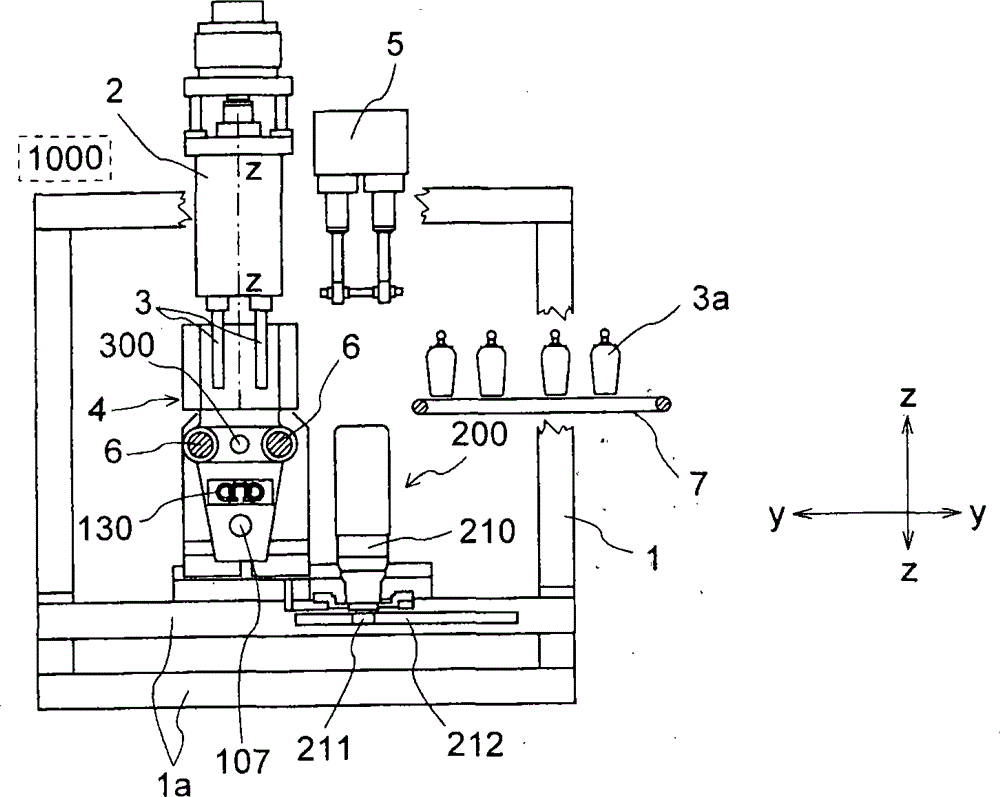
As shown in the figure, according to equipment of the present invention, comprise the support frame 1 with column and cross member 1a, for the device 2 of squeezable plastic tube 3, for the first operating means 100 of X-X opening/closing mould 4 along the longitudinal direction, for move moulds 4 the second operating means 200, blow nozzle 5 and be attached to described support frame for transporting the device 7 of molded container 3a along transverse direction Y-Y.
Described mould 4 is formed by two half mold 4a, 4b, two half mold 4a, 4b arrange symmetrically with respect to symmetrical fixed reference axis Z-Z, and with at a pair of each flange 14a, the 14b installing on the guide rail 6 of circular cross section, form one, described guide rail 6 is connected on framework 1 by means of support lugn 11, described support lugn 11 also forms one with the guide rail 12 sliding on track 13, and described track 13 is fixed on framework 1.
In more detail, describedly for X-X along the longitudinal direction, move two half mold 4a, the first operating means 100 of 4b comprises motor 101, described motor 101 Z-Z that parallels to the axis arranges, cam 101b (Fig. 3) is installed on the axle 101a of motor 101, the opposite end of described cam is connected to the connecting rod 104a being connected by means of pin 102c, the end of 104b, connecting rod 104a, 104b is hinged with the first half mold 4a and rear plate 106 respectively, then plate 106 is connected in the second half mold 4b by means of horizon bar 6, like this, when the first half mold 4a owing to being arranged between sleeve 6a and when freely move on bar 6, half mold 4b and post 6 form one, there is no each other relative motion.Between rear plate 106 and two half mold 4a, 4b, be also furnished with fixedly tie-rod 107, to guarantee that two half mold 4a, 4b close when bearing the impetus of operating system 100 so that keeping parallelism each other during molded operation.
One lazy-tongs 130 are arranged between flange 14b, 14a, and it can make the second half mold 4b with respect to the first half mold 4a symmetric motion, thereby make mould 4 with respect to the symmetrical opening/closing of vertical fixed reference axis Z-Z.
Described lazy-tongs 130 comprise the first tooth bar 131b, and described the first tooth bar 131b and flange 14b are integrally formed, and can be meshed with gear wheel 132, and gear wheel 132 is meshed with the second tooth bar 131a again, and the second tooth bar 131a and flange 14a are integrally formed.
For this structure, actuating by means of cam 101b and connecting rod 104a, 104b, the operation of motor 101 makes half mold 4a produce in one direction displacement, and make half mold 4b produce in the opposite direction the displacement of formed objects, connecting rod 104a, 104b make the whole assembly consisting of rear plate 106, bar 6 and half mold support lugn 14b produce displacement via the motion of sychronisation 130, make to produce in the opposite direction displacement by the flange 14a of connecting rod 104a direct control simultaneously.
Describedly for the second operating means 200 along mobile (displacing) die unit of transverse direction Y-Y (Fig. 1), by least one gear motor 210, formed, the axle of gear motor 210 carries pinion 211, pinion 211 can be parallel to that transverse direction Y-Y arranges and the linear gear rack 212 of one of cross member 1a that is fixed on the framework 1 of equipment is meshed.According to equipment of the present invention, also comprise for regulating two half mold 4a, 4b with respect to the adjusting device 300 of the distance of symmetrical fixed reference axis Z-Z.
In more detail, described adjusting device 300 comprises the header board 301 being integrally formed with two circular guideways 6 and the sleeve 302 that is attached to described header board 301, and described sleeve 302 has the screw thread that can be engaged on the tie-rod 107 that is fixed on flange 14b.
Sleeve 302 has the screw thread of direction and tie-rod opposite direction, like this, the rotation of sleeve 302 makes flange 14b longitudinally produce displacement, the displacement of flange 14b makes another flange 14a produce symmetrical displacement via synchronizer 130, and result makes two half mold 4a, 4b arrange symmetrically with respect to fixed reference axis Z-Z.
This equipment also comprises the locking ring 304 for fixedly relative distance is set.
For this structure, as shown in Fig. 2,3,5 and 6, the motion of mould is performed as follows:
-after regulating two half mold 4a, the 4b relative distance apart from axis Z-Z via adjusting device 300;
-the programming by suitable and control device 1000 coordinate and the program controlled in;
-motor 101 moves (Fig. 2,3) in one direction so that cam 101b rotation, to flange 14b, 14a are produced to pull/impetus, like this, described flange is promoted symmetrically/is pulled respectively away from axis Z-Z, so that opens two half mold 4a, 4b;
-by the second operating means 200, take whole mold supporting unit 4 to squeezable plastic tube 3 belows;
-motor 101 moves in the direction with aforementioned opposite direction, and like this, flange 14b, 14a are pushed to respectively/pull to symmetrical fixed reference axis Z-Z, so that two half mold 4a, 4b close on pipe 3;
210 operations of-gear motor, like this, the rotation of transmission device 211 on tooth bar 212 makes whole moulding unit along transverse direction Y-Y, produce displacement below blowing platform 5, carries out the molded of container on blowing platform 5;
-again operate the first operating means 100, to open two half mold 4a, 4b;
-remove the container 3a being molded, and by the removing (evacuation) being connected, install 7 they are seen off; With
-according to said procedure, start new circulation.
This shows, owing to transmitting the opening/closing motion of mould by means of two connecting rods point-blank, can greatly simplify the parts that form transmission system, thereby reduce the possibility of fault and the appearance of play, and can realized constant thrust by the center of the symmetrical half mold that close, and with regard to bull also accurate centering.
Owing to there is tie-rod 107 between rear plate and half mold, can also improve described parts being arranged in parallel in the down periods.
In addition, can predict, gear motor 210 can be controlled by means of 1000 programming devices that schematically illustrate in Fig. 1, and described programming device can be electric mechanical type, electronic type and/or procedure type.

Claims (12)

1. for a molding equipment of molded container (3a), it comprises: for the squeeze unit (2) of squeezable plastic tube (3), blowing unit (5), be used for holding the mould (4) of container (3a), described mould (4) is formed by the first and second half molds (4a, 4b), (X-X) motion along the longitudinal direction during the first operating means (100) that described the first and second half molds (4a, 4b) are connected in operation, and the first and second half molds (4a, 4b) are with respect to fixed reference axis (Z-Z) symmetric motion perpendicular to described longitudinal direction, and the transverse shifting unit being formed by mould (4) and the second operating means (200) of being connected, when operation the second operating means (200), described the second operating means (200) makes mould along horizontal direction (Y-Y), to move to the second place of aliging with blowing unit (5) substantially from the primary importance of aliging with squeeze unit (2) substantially, vice versa, for operating along the longitudinal direction the first and second half mold (4a, described the first operating means (100) 4b) comprises at least one motor (101), the axle (101a) of described motor (101) have key on it for activating pair of links (104a, cam 104b) (101b), this is to connecting rod (104a, 104b) arrange point-blank, and be connected respectively on the first half mold (4a) and rear plate (106), wherein, this equipment comprises for regulating the first and second half mold (4a, 4b) apart from the relative distance of fixed reference axis (Z-Z) to correctly close the adjusting device (300) of the first and second half molds,
Described molding equipment is characterised in that,
Described the first and second half molds (4a, 4b) are integrally formed with the first and second flanges (14a, 14b) that are arranged in pair of guide rails (6) respectively,
First connecting rod (104a) is directly connected on the first flange (14a) in first and second flanges (14a, 14b) of the first and second half molds, and another connecting rod (104b) is connected in second flange (14b) of the second half mold by means of rear plate (106), described rear plate (106) is integrally formed at the relative end, the end with for attachment to the second half mold (4b) of guide rail (6)
One lazy-tongs (130) are arranged between the first and second flanges (14a, 14b) of the first and second half molds (4a, 4b), and it can cause that the second half mold (4b) is with respect to the first half mold (4a) symmetric motion,
Described adjusting device (300) comprises the header board (301) being integrally formed with two circular guideways (6) and the sleeve (302) that is attached to described header board, and described sleeve (302) has the screw thread that can be engaged on the tie-rod (107) being integrally formed with the second flange (14b).
2. molding equipment as claimed in claim 1, is characterized in that, described guide rail (6) has circular cross-section.
3. molding equipment as claimed in claim 1, is characterized in that, described guide rail (6) is connected in framework (1) by means of support lugn (11).
4. molding equipment as claimed in claim 3, is characterized in that, described support lugn (11) is integrally formed with the upper guide rail (12) sliding of track (13) being fixed on framework (1).
5. molding equipment as claimed in claim 4, is characterized in that, described guide rail (6) runs through the first flange (14a) via corresponding sleeve (6a).
6. molding equipment as claimed in claim 1, it is characterized in that, described lazy-tongs (130) comprise the first tooth bar (131b), described the first tooth bar (131b) is integrally formed with the second flange (14b), and can be meshed with gear wheel (132), described gear wheel (132) is meshed with the tooth of the second tooth bar (131a) again, and the second tooth bar (131a) is integrally formed with the first flange (14a).
7. molding equipment as claimed in claim 1, it is characterized in that, described the second operating means (200) is comprised of at least one gear motor (210), described gear motor has an axle, and the bearing of described gear motor carries the pinion (211) that can be meshed with linear gear rack (212).
8. molding equipment as claimed in claim 7, is characterized in that, described linear gear rack (212) is parallel to horizontal direction (Y-Y) and arranges.
9. molding equipment as claimed in claim 7, is characterized in that, described linear gear rack (212) is fixed on one of the cross member (1a) of the framework (1) of equipment.
10. molding equipment as claimed in claim 1, is characterized in that, the screw thread of described sleeve (302) and described tie-rod (107) has contrary direction.
11. molding equipments as claimed in claim 1, is characterized in that, described adjusting device (300) comprises the locking ring (304) for lock adjustment device.
12. molding equipments as claimed in claim 1, is characterized in that, described molding equipment comprises for controlling the programming device (1000) of the first operating means (100) and the second operating means (200).
CN200710180254.6A 2006-10-16 2007-10-16 Machine for moulding plastic containers using means for moving mould-support unit comprising two in-line connecting rods Active CN101229684B (en)

Applications Claiming Priority (2)

Application Number Priority Date Filing Date Title
ITMI2006A001982 2006-10-16
IT001982A ITMI20061982A1 (en) 2006-10-16 2006-10-16 MACHINE FOR THE FORMATUTRA OF PLASTIC CONTAINERS WITH MEANS OF HANDLING THE DOUBLE ROD MOLD GROUP IN LINE

Publications (2)

Publication Number Publication Date
CN101229684A CN101229684A (en) 2008-07-30
CN101229684B true CN101229684B (en) 2014-03-12

Family

ID=38947370

Family Applications (1)

Application Number Title Priority Date Filing Date
CN200710180254.6A Active CN101229684B (en) 2006-10-16 2007-10-16 Machine for moulding plastic containers using means for moving mould-support unit comprising two in-line connecting rods

Country Status (5)

Country Link
US (1) US7874828B2 (en)
EP (1) EP1914061B1 (en)
CN (1) CN101229684B (en)
ES (1) ES2543591T3 (en)
IT (1) ITMI20061982A1 (en)

Families Citing this family (7)

* Cited by examiner, † Cited by third party
Publication number Priority date Publication date Assignee Title
ES2387543T3 (en) * 2009-03-10 2012-09-25 Antonio Gumercindo Pavan Blow molding machine to manufacture thermoplastic parts and containers
DE102012109499A1 (en) 2012-10-05 2014-04-10 Kautex Maschinenbau Gmbh Closing frame i.e. three-plate closing frame, for use in blow molding machine, has guides arranged on base frame, drive unit fastened to drive plate, and crank gear for connecting drive shaft with one of carrier plates in articulated manner
PT2909000T (en) * 2012-10-16 2019-02-26 Kocher Plastik Maschinenbau Gmbh DEVICE FOR PRODUCING PACKAGING PRODUCTS FROM SYNTHETIC MATERIALS
ITMI20131555A1 (en) * 2013-09-20 2015-03-21 Magic Mp Spa TOGETHER FOR BLOWING PRE-FORMED CONTAINERS IN THERMOPLASTIC MATERIAL
US11148330B2 (en) * 2017-01-25 2021-10-19 Lotes Co., Ltd Injection molding machine device
FR3062335B1 (en) * 2017-07-21 2021-03-19 Sidel Participations PROCESS FOR MAINTENANCE OF A CONTAINER FORMING PLANT, INCLUDING A RESYNCHRONIZATION PROCEDURE
CN111417298B (en) * 2020-03-30 2021-04-13 深圳市洲明科技股份有限公司 A reprocess device for COB Mini-LED lamp plate

Family Cites Families (10)

* Cited by examiner, † Cited by third party
Publication number Priority date Publication date Assignee Title
US3277534A (en) * 1963-11-07 1966-10-11 Union Carbide Corp Apparatus for molding hollow plastic articles
GB1477098A (en) * 1975-09-17 1977-06-22 Korsch H Apparatus for fabricating hollow articles from thermoplastic material
US4421472A (en) * 1981-08-31 1983-12-20 R & B Machine Tool Company Clamp for blow molding machine
US4673076B1 (en) * 1984-09-04 2000-02-01 Kearney & Trecker Corp Rotary shuttle for machine tools
US5478229A (en) * 1993-01-29 1995-12-26 The Japan Steel Works, Ltd. Apparatus for forming hollow article
JP2988809B2 (en) 1993-07-21 1999-12-13 株式会社タハラ Mold clamping device for blow molding machine
US6102685A (en) * 1997-02-25 2000-08-15 Kao Corporation Mold-clamping device of blow molding machine
DE69740164D1 (en) * 1997-02-25 2011-05-19 Kao Corp blow molding machine
JP3914632B2 (en) 1998-04-02 2007-05-16 株式会社タハラ Hollow molding machine
ITMI20012230A1 (en) 2001-10-24 2003-04-24 Magic Mp Spa BLOWER FORMING MACHINE FOR PLASTIC CONTAINERS EQUIPPED WITH ELECTRIC TYPE DRIVE DEVICES

Also Published As

Publication number Publication date
EP1914061B1 (en) 2015-06-10
US7874828B2 (en) 2011-01-25
CN101229684A (en) 2008-07-30
EP1914061A3 (en) 2010-08-11
EP1914061A2 (en) 2008-04-23
ITMI20061982A1 (en) 2008-04-17
ES2543591T3 (en) 2015-08-20
US20080152746A1 (en) 2008-06-26

Similar Documents

Publication Publication Date Title
CN101229684B (en) Machine for moulding plastic containers using means for moving mould-support unit comprising two in-line connecting rods
US6139305A (en) Apparatus for production of injection molded articles from at least two plastic melts
JP4112658B2 (en) Blow molding machine
RU2481948C2 (en) Device for moring reservoirs from synthetic material by blowing
CN104985743B (en) Inclined injection machine
CN101237982B (en) Blow-moulding station for a container stretching/blowing plant and plant comprising one such assembly
CN105711060B (en) Multiple-station rotation forming machine
CN204249339U (en) Multiple-station rotation forming machine
KR900007347B1 (en) Blow Molding Device of Synthetic Resin
WO2012111728A1 (en) Blow-mold machine
TWI610792B (en) Biaxial extension blow molding device
CN101885234A (en) Hollow forming machine for injecting, drawing and blowing plastic by one-step method
JPH07506543A (en) blow molding machine
JPS61500657A (en) plastic pipe manufacturing equipment
ITMI20012230A1 (en) BLOWER FORMING MACHINE FOR PLASTIC CONTAINERS EQUIPPED WITH ELECTRIC TYPE DRIVE DEVICES
CN108472857B (en) Mold clamping device and method
JP2016209921A (en) Metal mold unit
EP1818158B1 (en) Machine for moulding plastic containers with linear-rack means for moving the mould-carrying unit
CN201169048Y (en) Injection stretch blow plastic bottle blower by one-step method
US20050238754A1 (en) Machine for forming plastic containers with a linear motor for moving the mould-support unit
CN201175990Y (en) Mould opening and closing device of blow molding machine
CN209036985U (en) A kind of plastic extrusion blowing blow moulding machine of segmented movable block pc barrel die
CN218477076U (en) Injection mold for armrest decoration frame
CN102173049A (en) Monorail type opening and closing die locking mechanism of plastic container stretching and blowing machine
CN101172388A (en) Toggle mode locking device of injection molding machine

Legal Events

Date Code Title Description
C06 Publication
PB01 Publication
C10 Entry into substantive examination
SE01 Entry into force of request for substantive examination
GR01 Patent grant
GR01 Patent grant