CN101223560B - Pathogen and particle detector system and method - Google Patents
Pathogen and particle detector system and method Download PDFInfo
- Publication number
- CN101223560B CN101223560B CN2006800259429A CN200680025942A CN101223560B CN 101223560 B CN101223560 B CN 101223560B CN 2006800259429 A CN2006800259429 A CN 2006800259429A CN 200680025942 A CN200680025942 A CN 200680025942A CN 101223560 B CN101223560 B CN 101223560B
- Authority
- CN
- China
- Prior art keywords
- light
- particle
- detector
- forward scattering
- sample slot
- Prior art date
- Legal status (The legal status is an assumption and is not a legal conclusion. Google has not performed a legal analysis and makes no representation as to the accuracy of the status listed.)
- Expired - Fee Related
Links
Images


Classifications
-
- G—PHYSICS
- G01—MEASURING; TESTING
- G01N—INVESTIGATING OR ANALYSING MATERIALS BY DETERMINING THEIR CHEMICAL OR PHYSICAL PROPERTIES
- G01N15/00—Investigating characteristics of particles; Investigating permeability, pore-volume or surface-area of porous materials
- G01N15/02—Investigating particle size or size distribution
- G01N15/0205—Investigating particle size or size distribution by optical means
-
- G—PHYSICS
- G01—MEASURING; TESTING
- G01N—INVESTIGATING OR ANALYSING MATERIALS BY DETERMINING THEIR CHEMICAL OR PHYSICAL PROPERTIES
- G01N21/00—Investigating or analysing materials by the use of optical means, i.e. using sub-millimetre waves, infrared, visible or ultraviolet light
- G01N21/17—Systems in which incident light is modified in accordance with the properties of the material investigated
- G01N21/47—Scattering, i.e. diffuse reflection
-
- G—PHYSICS
- G01—MEASURING; TESTING
- G01N—INVESTIGATING OR ANALYSING MATERIALS BY DETERMINING THEIR CHEMICAL OR PHYSICAL PROPERTIES
- G01N33/00—Investigating or analysing materials by specific methods not covered by groups G01N1/00 - G01N31/00
- G01N33/48—Biological material, e.g. blood, urine; Haemocytometers
- G01N33/50—Chemical analysis of biological material, e.g. blood, urine; Testing involving biospecific ligand binding methods; Immunological testing
- G01N33/53—Immunoassay; Biospecific binding assay; Materials therefor
-
- G—PHYSICS
- G01—MEASURING; TESTING
- G01N—INVESTIGATING OR ANALYSING MATERIALS BY DETERMINING THEIR CHEMICAL OR PHYSICAL PROPERTIES
- G01N15/00—Investigating characteristics of particles; Investigating permeability, pore-volume or surface-area of porous materials
- G01N15/01—Investigating characteristics of particles; Investigating permeability, pore-volume or surface-area of porous materials specially adapted for biological cells, e.g. blood cells
- G01N2015/019—Biological contaminants; Fouling
-
- G—PHYSICS
- G01—MEASURING; TESTING
- G01N—INVESTIGATING OR ANALYSING MATERIALS BY DETERMINING THEIR CHEMICAL OR PHYSICAL PROPERTIES
- G01N2201/00—Features of devices classified in G01N21/00
- G01N2201/06—Illumination; Optics
- G01N2201/062—LED's
- G01N2201/0624—Compensating variation in output of LED source
Landscapes
- Chemical & Material Sciences (AREA)
- Health & Medical Sciences (AREA)
- Life Sciences & Earth Sciences (AREA)
- Immunology (AREA)
- Physics & Mathematics (AREA)
- Analytical Chemistry (AREA)
- Biochemistry (AREA)
- General Health & Medical Sciences (AREA)
- General Physics & Mathematics (AREA)
- Pathology (AREA)
- Dispersion Chemistry (AREA)
- Engineering & Computer Science (AREA)
- Biomedical Technology (AREA)
- Hematology (AREA)
- Molecular Biology (AREA)
- Urology & Nephrology (AREA)
- Biotechnology (AREA)
- Cell Biology (AREA)
- Microbiology (AREA)
- Food Science & Technology (AREA)
- Medicinal Chemistry (AREA)
- Investigating Or Analysing Materials By Optical Means (AREA)
- Investigating, Analyzing Materials By Fluorescence Or Luminescence (AREA)
- Sampling And Sample Adjustment (AREA)
Abstract
Description
相关申请 related application
本申请要求享有2005年7月15日提交的未诀的美国临时申请的权益,该申请的序列号为60/700,008,题目为“Pathogen and Particle Detector System and Method”,在此引入其全部内容作为参考。 This application claims the benefit of co-pending U.S. Provisional Application Serial No. 60/700,008, filed July 15, 2005, and entitled "Pathogen and Particle Detector System and Method," which is hereby incorporated in its entirety as refer to. the
技术领域technical field
本发明一般涉及一种用于检测气悬颗粒或水悬颗粒的系统和方法,以及更尤其涉及一种用于检测气悬颗粒或水悬颗粒及通过大小分类该测得颗粒的系统和方法。本发明在检测和通过大小分类过敏原和生物战争药剂方面具有特殊用途,以下将结合该用途来说明本发明,但本发明也可具有其它的用途。 The present invention relates generally to a system and method for detecting air- or water-suspended particles, and more particularly to a system and method for detecting air- or water-suspended particles and classifying the detected particles by size. The invention will be described below in connection with the specific utility of detecting and classifying by size allergens and biological warfare agents, but the invention may also have other applications. the
背景技术Background technique
包含释放诸如炭疽杆菌(anthrax)等生物战剂的都市恐怖攻击行为目前已成为值得关注的问题。武器性炭疽菌孢子由于可进入人类肺部而具有极高的危险性。对于人类而言,炭疽菌孢子的致死吸入剂量LD50(足以杀死50%暴露者的致死剂量)约为2,500至50,000个孢子,参阅T.V.Inglesby等人在1999年标题为“生物武器的炭疽菌”,JAMA第281卷第1735页,的发表文献。一些其它可能的武器性生物制剂为耶尔森氏杆菌(鼠疫)、肉毒梭状芽孢杆菌(肉毒中毒)以及土拉弗朗西斯菌(francisella tularensis)。鉴于此种潜在性的威胁,目前亟需一种能检测此类攻击的早期预警系统。 Urban terror attacks involving the release of biological warfare agents such as anthrax are currently a matter of concern. Weaponized anthrax spores are extremely dangerous because they can enter the lungs of humans. For humans, the lethal inhalation dose LD50 (lethal dose sufficient to kill 50% of those exposed) of anthrax spores is approximately 2,500 to 50,000 spores, see T.V. Inglesby et al. 1999 titled "Anthrax for biological weapons" , JAMA Vol. 281, p. 1735, published literature. Some other possible weapon biological agents are Yersinia (plague), Clostridium botulinum (botulism), and Francisella tularensis. In view of this potential threat, there is an urgent need for an early warning system that can detect such attacks. the
激光颗粒计数器是已知的检测工具,其引导激光光线通过一样本,并检测和分析通过该样本的光线以检测来自样本内颗粒的散射光。现有的设计用于检测散射光的检测器或颗粒计数器的一个问题在于必需从入射照明光源信号中萃取出散射信号。此包含从噪声极多的背景(来自激光光源的炫光)中检测一弱信号(来自细颗粒的散射光)。此特性为长久以来造成激光颗粒计数器的仪器检测困难的主要原因。传统上设计的激光颗粒计数器运用高价和精细的装置以降 低来自激光光源的眩光以及从大量背景噪声中测量颗粒散射光,因而使计数器变得极为脆弱和昂贵。目前,传统上设计的激光颗粒计数器均极脆弱和昂贵,因此不适用于此应用用途中。用于激光颗粒计数的传统技术包括测量颗粒速度并推算出大小信息的激光多普勒(Doppler)法、测定颗粒通过一感应区所需时间的瞬时时间法(transient time method)以及仅能够测定小颗粒的广角多传感器设计。在T.H.Jeys等人于1998年在Proc.IRIS Active Systems期刊第1卷第235页中叙述一种利用脉冲紫外线(UV)激光的激光诱发荧光的生物传感器。此生物传感器能够检测每升空气中5个颗粒的气雾浓度,但其造价极为昂贵并且脆弱。其它颗粒计数器由奥勒冈州Grants Pass市的Met One Instrument有限公司、Colorado的Boulder市的Particle Measurement Systems有限公司,以及加州Anaheim市的Terra国际股份有限公司制造。基于设计上的关系,这些颗粒计数器的构造需要极精密的光学对准及极为敏感的传感器和电子仪器。这些产品均朝向实验室使用的方向发展并且花费数千美元用于单一元件。因此,不适合作为现场使用的检测器,也不适合作为专用于生物战药剂检测的设计。 Laser particle counters are known detection tools that direct laser light through a sample and detect and analyze the light passing through the sample to detect scattered light from particles within the sample. A problem with existing detectors or particle counters designed to detect scattered light is the necessity to extract the scattered signal from the incident illumination source signal. This involves detecting a weak signal (scattered light from fine particles) from an extremely noisy background (flare from a laser light source). This characteristic has long been the main reason for the instrumental detection difficulties of laser particle counters. Traditionally designed laser particle counters use expensive and elaborate setups to reduce glare from the laser light source and to measure particle scattered light from a lot of background noise, making the counters extremely fragile and expensive. Currently, traditionally designed laser particle counters are too fragile and expensive to be suitable for this application. Traditional techniques for laser particle counting include laser Doppler (Doppler) method that measures particle velocity and deduces size information, instantaneous time method (transient time method) that measures the time required for particles to pass through a sensing area, and can only measure small particles. Wide-angle multi-sensor design for particles. A laser-induced fluorescence biosensor utilizing pulsed ultraviolet (UV) lasers is described in T.H. Jeys et al., 1998, Proc. IRIS Active Systems, Vol. 1, p. 235. The biosensor can detect aerosol concentrations of 5 particles per liter of air, but is extremely expensive and fragile. Other particle counters are manufactured by Met One Instrument, Inc. of Grants Pass, Oregon; Particle Measurement Systems, Inc. of Boulder, Colorado; and Terra International, Inc. of Anaheim, California. As a matter of design, the construction of these particle counters requires extremely precise optical alignment and extremely sensitive sensors and electronics. These products are all geared toward laboratory use and cost thousands of dollars for a single component. Therefore, it is not suitable as a detector for field use, nor is it suitable as a design dedicated to the detection of biological warfare agents. the
已设计出可检测流体悬浮过敏原颗粒的各种检测器,其可在当检测到空气样本中颗粒数目超过一预设最小值时对敏感者提出警告。这些检测均描述于Hamburger等人的美国专利案No.5,646,597、No.5,969,622、No.5,986,555、No.6,008,729和No.6,087,947号中。这些检测器均包含引导一光束通过一环境空气样本,使得部分光束将被空气中的任何颗粒所散射,用于传输仅在对应于预设过敏原大小范围的预定角度范围中散射的光的光束阻挡装置,以及一用于检测该传输光线的检测器。该检测器所测得的光线若超过一预定值时,则启动一警报。这些检测器虽然根据是否存在有过敏原颗粒足以用于提供警告指示,但是其并不适合用于现场的布署并且不符合作为检测生物战药剂的病原检测器的更严格需求。 Various detectors have been designed to detect allergen particles suspended in fluids, which can alert sensitive individuals when the number of particles detected in an air sample exceeds a preset minimum value. These assays are described in US Patent Nos. 5,646,597, 5,969,622, 5,986,555, 6,008,729 and 6,087,947 to Hamburger et al. These detectors each comprise directing a beam of light through a sample of ambient air such that a portion of the beam will be scattered by any particles in the air for transmitting light scattered only in a predetermined angular range corresponding to a predetermined range of allergen sizes blocking means, and a detector for detecting the transmitted light. If the light detected by the detector exceeds a predetermined value, an alarm is activated. These detectors, while adequate for providing warning indications based on the presence of allergen particles, are not suitable for deployment in the field and do not meet the more stringent requirements of pathogen detectors for detecting biological warfare agents. the
发明内容 Contents of the invention
本发明提供一种改良的病原和颗粒检测的系统和方法。更明确而言,本发明发展出一种完全利用非弹性散射强度(即来自颗粒的荧光)的独特角度分布模式的新颖荧光信号收集方法。理论上和实验上均已证明颗粒的非弹性散射在后向(最强)和前向(第二强)方向上具有较佳的强度角度分布(参考文献1 “Backward-enhanced fluorescence from clusters of microspheres and particles of tryptophan”Yong-Le Pan等人,Appl.Opt.第41卷,第2994页,2002;参考文献2“Angle-and size-dependent characteristics of incoherent Raman and fluorescent scattering by microspheres”Igor Veselovskii Appl.Opt.第41卷,第5783页,2002。简言之,在一实施例中,该系统包括一用以提供具有光源波长的电磁辐射束的激发光源。如二色性分光镜等第一波长选择装置置于可受到电磁辐射光束照射的位置。第一波长选择装置可传送至少一部分任何具有光源波长的辐射以及反射其它波长的辐射。含颗粒的介质(medium)置于可被电磁辐射光束照射的位置。至少一部分电磁辐射光束在介质内被散射,该散射电磁辐射包括前向散射电磁辐射及后向散射电磁辐射。设置光检测器以收集前向和后向散射电磁辐射。
The present invention provides an improved system and method for pathogen and particle detection. More specifically, the present invention develops a novel fluorescence signal collection method that fully exploits the unique angular distribution pattern of inelastically scattered intensity (ie, fluorescence from particles). Inelastic scattering from particles has been demonstrated both theoretically and experimentally to have a better angular distribution of intensity in the backward (strongest) and forward (second strongest) directions (Ref. 1 "Backward-enhanced fluorescence from clusters of microspheres and particles of tryptophan" Yong-Le Pan et al., Appl.Opt. Vol. 41, p. 2994, 2002;
本发明提供一种颗粒检测系统,包含:外壳,其具有样本槽区;光源,其位于所述样本槽区的一侧上,用于传送聚焦光束通过所述样本,因而使部分所述光束被所述样本区内的各种大小颗粒以各种角度散射,而所述光束未散射部分则保持未被散射状态;光束阻挡装置,其位于所述样本槽区的相反侧上,用于阻挡所述光束的至少一部分未散射部分以及用于限制颗粒的测定范围;特征在于,包含:第一检测器,其设置于所述光束阻挡装置后方的路径中,用于检测一部分的前向散射光,并且产生含有所述光路径中落在预设粒径范围内的前向散射颗粒数目信息的输出;第二检测器,其位于空气样本槽区的光源侧上,用于检测一部分后向散射光,并且产生含有在光路径中落在预设粒径范围内的后向散射颗粒数目信息的输出。 The present invention provides a particle detection system comprising: a housing having a sample well; a light source located on one side of the sample well for transmitting a focused beam of light through the sample, whereby a portion of the light beam is Particles of various sizes within the sample area are scattered at various angles, while the unscattered portion of the beam remains unscattered; beam blocking means, located on the opposite side of the sample well area, block the At least a part of the unscattered part of the light beam and used to limit the measurement range of the particles; characterized by comprising: a first detector, which is arranged in the path behind the light beam blocking device, and is used to detect a part of the forward scattered light, and producing an output containing information on the number of forward scattered particles in said light path falling within a predetermined particle size range; a second detector, located on the light source side of the air sample well, for detecting a portion of the backscattered light , and produces an output containing information on the number of backscattered particles in the optical path that fall within a predetermined particle size range. the
本发明提供一种检测病原体和颗粒的方法,所述方法包含以下步骤:发射光束;以及传输至少一部分该光束通过第一波长选择器件;其特征在于以该部分光束照射含颗粒的介质,其中颗粒以前向及后向方向来散射所述光线;以及检测并测量前向散射光和后向散射光。 The present invention provides a method of detecting pathogens and particles, said method comprising the steps of: emitting a beam of light; and transmitting at least a part of the beam of light through a first wavelength selective device; characterized in that the part of the beam of light irradiates a medium containing particles, wherein the particles scattering the light in forward and backward directions; and detecting and measuring the forward scattered light and the backward scattered light. the
在本发明的一个方面中,光源包含发光二极管;系统包括用于将来自所述发光二极管的光线塑造成接近准直光束的光学透镜。在本发明的另一个方面中,光源包括光学透镜,用于塑造光和/或从光束去除噪音。 In one aspect of the invention, the light source comprises a light emitting diode; the system comprises an optical lens for shaping light from said light emitting diode into a nearly collimated beam. In another aspect of the invention, the light source includes an optical lens for shaping the light and/or removing noise from the light beam. the
在检视下列附图和详细说明之后,本领域普通技术人员将可更清础了解本发明的其它系统、方法、特征及优点。本发明的其它此类系统、方法、特征和 优点均属于本说明书内容及本发明范围内,并且受到后附权利要求书的保护。 Those of ordinary skill in the art will have a better understanding of other systems, methods, features and advantages of the present invention after reviewing the following figures and detailed description. Other such systems, methods, features and advantages of the present invention all belong to the contents of this description and the scope of the present invention, and are protected by the appended claims. the
附图说明 Description of drawings
参考下列附图可更加了解本发明的多种方案。附图内的部件并不需依照比例绘制,而是强调能够清楚图解本发明的原理。此外,在附图中,在该整个附图中均以相同组件符号来代表相对应的部件。 Various aspects of the invention can be better understood with reference to the following figures. The components in the figures are not necessarily to scale, emphasis instead being placed upon illustrating clearly the principles of the invention. In addition, in the drawings, corresponding components are denoted by the same reference numerals throughout the drawings. the
图1是根据本发明第三示例性实施方式的用于一流体悬浮颗粒检测系统的光学系统; 1 is an optical system for a fluid suspended particle detection system according to a third exemplary embodiment of the present invention;
图2是根据本发明的第三示例性实施方式并且结合图1的光学系统的颗粒检测系统方块图; 2 is a block diagram of a particle detection system in conjunction with the optical system of FIG. 1 according to a third exemplary embodiment of the present invention;
图3是根据本发明的第四示例性实施方式的用于一流体悬浮颗粒检测系统701的光学系统; 3 is an optical system for a fluid suspended particle detection system 701 according to a fourth exemplary embodiment of the present invention;
图4是根据本发明的第三示例性实施方式并且结合图3的光学系统的颗粒检测系统方块图; 4 is a block diagram of a particle detection system in conjunction with the optical system of FIG. 3 according to a third exemplary embodiment of the present invention;
图5是米氏散射截面与颗粒半径的关系图; Fig. 5 is the relationship figure of Mie scattering cross section and particle radius;
图6是根据本发明的第四示例性实施方式,由模拟数字转换器、窗口比较器电路和控制输出显示器所构成的脉波高度测量电路的方块图; Fig. 6 is according to the 4th exemplary embodiment of the present invention, the block diagram of the pulse wave height measuring circuit that is made of analog-to-digital converter, window comparator circuit and control output display;
图7是根据本发明的第四示例性实施方式的模拟数字转换器示意图; Fig. 7 is a schematic diagram of an analog-to-digital converter according to a fourth exemplary embodiment of the present invention;
图7A是根据本发明的第四示例性实施方式,模拟数字转换器在各点的输出的图解说明; 7A is a diagrammatic illustration of the output of an analog-to-digital converter at various points according to a fourth exemplary embodiment of the present invention;
图8为说明粒径分布柱状图的范例; Figure 8 is an example illustrating a histogram of particle size distribution;
图9示出四种代谢物的荧光发光光谱。 Figure 9 shows the fluorescence emission spectra of four metabolites. the
具体实施方式 Detailed ways
图1显示用于根据本发明的第一示例性实施方式的流体悬浮颗粒检测器系统中的光学系统。该系统的第一示例性实施方式特别是有关于用来检测恐怖分子或他人有意散播的气悬或水悬性生化恐怖战剂,但也可用于都市设施以检测可能存在于自然界如霉菌或细菌或是如食品和制造工厂等其它工业设施意外、不慎、自然或刻意释出有害浓度的其它气悬或水悬颗粒,以及用于室内清净的用途被。 Fig. 1 shows an optical system used in a fluid suspended particle detector system according to a first exemplary embodiment of the present invention. The first exemplary embodiment of the system is particularly concerned with detecting airborne or aqueous bioterrorism agents intentionally distributed by terrorists or others, but can also be used in urban settings to detect possible presence in nature such as mold or bacteria Or other industrial facilities such as food and manufacturing plants that accidentally, accidentally, naturally or intentionally release harmful concentrations of other airborne or water-suspended particles, and are used for indoor cleaning. the
术语“流体传播颗粒(fluid borne particles)”一词在此处意指经由空气和水传播的颗粒。 The term "fluid borne particles" as used herein means air- and water-borne particles. the
术语“病原体”一词在此处指任何经由空气或水媒介的颗粒、生物制剂或毒素,若其在空气或水源中存在足够量时可能造成暴露于这些颗粒的人类潜在性的伤害或甚至死亡。此处“生物制剂(biological agent)”定义为任何的微生物、病原体或感染物质、毒素、生物毒素,或不论来源或制造方法经由任何此类微生物、病原体或感染物质所产生的任何天然、生物工程或合成成分。此类生物制剂包括例如生物毒素、细菌、病毒、立克次氏体、孢子、真菌和原虫,以及本领域中公知的其它任何病原体。 The term "pathogen" as used herein refers to any airborne or waterborne particle, biological agent or toxin which, if present in sufficient quantities in the air or water source, could cause potential injury or even death to a human being exposed to the particle . "Biological agent" is defined herein as any microorganism, pathogenic or infectious agent, toxin, biotoxin, or any natural, biologically engineered or synthetic ingredients. Such biological agents include, for example, biotoxins, bacteria, viruses, rickettsiae, spores, fungi, and protozoa, as well as any other pathogen known in the art. the
“生物毒素”为活体植物、动物或微生物所产生或衍生出的毒性物质,但也可通过化学方法制造或改造。然而,毒素通常由宿主生物所自然产生(即,贝类毒素由海藻所产生),但实验室环境内已可制造出基因改造和/或合成制造的毒素。与微生物相较之下,毒素具有相对较简单的生化组成物并且无法自我繁殖。在许多方面,生物毒素可视为是一种化学剂。此类生物毒素为例如肉毒素和破伤风毒素、葡萄球菌肠毒素B、梭霉菌毒素、菎麻毒素(ricin)、贝类毒素(saxitoxin)、志贺(Shiga)和类志贺毒素、树眼镜蛇毒素(dendrotoxins)、海蛇毒素-b(erabutoxin-b)以及其它已知的毒素。 "Biotoxins" are toxic substances produced or derived from living plants, animals or microorganisms, but may also be chemically manufactured or modified. However, toxins are generally produced naturally by the host organism (ie, shellfish toxins are produced by algae), but genetically modified and/or synthetically produced toxins have been produced in laboratory settings. In contrast to microorganisms, toxins have a relatively simple biochemical composition and are unable to reproduce themselves. In many respects, a biotoxin can be thought of as a chemical agent. Such biotoxins are for example botulinum and tetanus toxins, staphylococcal enterotoxin B, clostridial toxins, ricin, saxitoxin, Shiga and shiga-like toxins, tree cobras Dendrotoxins, erabutoxin-b, and other known toxins. the
该检测系统的设计为检测空气或水传播的颗粒及产生显示例如检测样本内各种颗粒尺寸范围中的颗粒数目的输出值,以及显示该些颗粒是否为生物性或非生物性颗粒。该系统在颗粒数量在正常背景下超过一预定值和/或为可能造成危害的生物有机体或生物制剂时也可发出警告信号或其它反应。 The detection system is designed to detect air or waterborne particles and produce an output indicating, for example, the number of particles in various particle size ranges within the detection sample, and whether the particles are biotic or abiotic. The system may also issue a warning signal or other response when the number of particles exceeds a predetermined value in a normal background and/or is a biological organism or biological agent that may cause a hazard. the
图1为用于根据本发明第一示例性实施方式的水悬颗粒检测系统的光学系统210。如图1所示,该光学系统210包括一激发光源212,用以提供具有一光源波长的电磁辐射光束214。在一个实施方式中,第一波长选择装置216包括一受到电磁辐射光束214所照射的二色分光镜(dichroic beamsplitter)。该第一波长选择装置216构造为传送至少一部分任何具有该光源波长的辐射以及反射其它波长的辐射。该第一波长选择装置216可反射来自激发光源212的可能混附波(spurious spectral emissions)。一部分电磁辐射光束214可被第一波长选择装置216反射朝向一功率监控检测器250。该功率监控检测器250可与激发光源212联系,以及视需要可作为维持该激发光源212恒定输出功率的 反馈回路中的一部分。可通过功率监控透镜256来集中被第一波长选择装置216所反射朝向功率监控检测器250的部分电磁辐射光束214。
FIG. 1 is an
含颗粒220的介质218置于可被电磁辐射光束214照射的位置。至少一部分电磁辐射光束214成为在介质218内的散射电磁辐射。该散射电磁辐射包括前向散射电磁辐射222及后向散射电磁辐射224。第一光学检测器226置于可接收后向散射电磁辐射224的位置。该后向散射电磁辐射224可通过第一波长选择装置216朝向光学检测器226被反射。第一波长选择装置216和光学检测器226之间可利用带通滤光器252以最小化来自电磁辐射光束214的任何背向散射光和/或用来选出准备测定的光谱的特定部分。第一波长选择装置216和光学检测器226之间可利用聚焦透镜254以聚焦朝向光学检测器226的后向散射电磁辐射224。
A medium 218 containing
如图1所示,可引导该前向散射电磁辐射222照射至第一光束阻挡透镜260。该第一光束阻挡透镜260可设计用于反射电磁辐射光束214中的非散射元素,以避免在光学检测器上产生眩光。第一光束阻挡透镜260具有附着于前表面用以反射电磁辐射光束214的非散射元素的材料,例如乙烯(vinyl)。第一光束阻挡透镜260的其它可能考虑事项已述于专利申请案序号No.11/193,204内,将其并入于本文中以供参照。
As shown in FIG. 1 , the forward scattered
该前向散射电磁辐射随后可被引导至第一光学组件262,其为一低通滤波器或类似第三示例性实施方式中的波长选择组件。第一光学组件262容许至少一部分前向散射电磁辐射222通过并反射掉一部分的前向散射电磁辐射222。更明确而言,该第一光学组件262可反射前向散射电磁辐射222的荧光信号部分,同时可让其余的前向散射电磁辐射222通过。第二光束阻挡透镜264可聚焦朝向颗粒检测器266的前向散射电磁辐射222的通过部分。该颗粒检测器266可为例如一用于测量该颗粒220的大小的光电二极管(photodiode)。
The forward scattered electromagnetic radiation may then be directed to a first
可引导该前向散射电磁辐射222的反射荧光信号部分通过介质218而返回后被第一波长选择装置216反射朝向光学检测器226。在第一波长选择装置216和光学检测器226之间可使用聚焦透镜254来聚焦朝向光学检测器226的前向散射电磁辐射222的反射荧光信号部分。
The portion of the reflected fluorescent signal that may guide the forward scattered
图2为根据本发明的第一示例性实施方式的颗粒检测系统的方块图,其纳入图1的光学系统210。该光学系统210包括引导电磁辐射光束214进入第一波长选择装置216的激发光源212。该电磁辐射光束214通过第一波长选择装置216进入介质218,并且一部分的电磁辐射光束214被后向散射至该第一光学检测器226,以及另一部分的电磁辐射光束214被前向散射朝向该颗粒检测器266。
FIG. 2 is a block diagram of a particle detection system incorporating the
两个信号除法器(signal divider)230A、230B将第一光学检测器226和颗粒检测器266的输出分别除以功率监控检测器250的输出。两个放大器232A、232B连接至该信号除法器230A、230B的输出端。一模拟数字转换器234连接至放大器232A、232B。一窗口比较电路(window comparator circuit)236连接至该模拟数字转换器234。一控制输出显示器(control and output display unit)238连接至该窗口比较电路236的输出端。一低信号检测电路240连接至激发光源212的输出端,其可提供该电磁辐射光束214的功率强度。该低信号检测电路240的输出端还连接至该控制输出显示器238。一警报装置242也连接至该控制输出显示器238。该控制输出显示器238可以是一计算机或定做的软件/硬件,以控制该颗粒检测器的操作。
Two
图3为用于根据本发明的第二示例性实施方式的水悬颗粒检测系统的光学系统。如图3所示,该光学系统310包括激发光源312,以提供具有一光源波长的电磁辐射光束314。一第一波长选择装置316,例如二色分光镜,置于可被电磁辐射光束314所照射的位置。该第一波长选择装置316构造为可传送至少一部分的任何具有光源波长的辐射以及反射其它波长的辐射。该第一波长选择装置316可反射来自激发光源312的可能混附波。一部分的电磁辐射光束314可被第一波长选择装置316反射朝向功率监控检测器350。该功率监控检测器350可与激发光源312联系,以及视需要可作为维持该激发光源312恒定输出功率的反馈回路中的一部分。可通过功率监控透镜356来聚焦被第一波长选择装置316反射朝向功率监控检测器350的电磁辐射光束314。
FIG. 3 is an optical system used in a water suspended particle detection system according to a second exemplary embodiment of the present invention. As shown in FIG. 3, the
含颗粒320的介质318置于可被电磁辐射光束314照射的位置。至少一部分电磁辐射光束312可成为该介质318内的散射电磁辐射。该散射电磁辐射包括前向散射电磁辐射322及后向散射电磁辐射324。第一光学检测器326设置用以接收后向散射电磁辐射324。该后向散射电磁辐射324可通过第一波长选择装置316被反射至光学检测器326。第一波长选择装置316和光学检测器326之间可利用带通滤光器352以最小化来自电磁辐射光束314的任何背向散射光 和/或用以选出准备测定的光谱的特定部分。第一波长选择装置316和光学检测器326之间可利用聚焦透镜354以聚焦朝向光学检测器326的后向散射电磁辐射324。
A medium 318 containing
如图3所示,该前向散射电磁辐射322可被引导而照射至第一光束阻挡透镜360。该第一光束阻挡透镜360设计用以反射电磁辐射光束314的非散射元素,其可避免光学检测器上的眩光。该前向散射电磁辐射随后可被引导至一光学组件370,其为第四示例性实施方式中的第二波长选择装置316。该第一光学组件370容许至少一部分前向散射电磁辐射322通过,并反射一部分的前向散射电磁辐射322。更明确而言,该第一光学组件370可反射前向散射电磁辐射322的荧光信号部分,同时可让其余的前向散射电磁辐射322通过。第二光束阻挡透镜364可聚焦朝向颗粒检测器366的前向散射电磁辐射322的通过部分。该颗粒检测器366可为例如一用于测定该颗粒320大小的光电二极管。
As shown in FIG. 3 , the forward scattered
可引导该前向散射电磁辐射322的反射荧光信号部分朝向第二光学检测器376。第一光学组件370和第二光学检测器376之间可使用一第二带通滤光器372,以最小化来自电磁辐射光束314的任何背向散射光和/或用以选出准备测定的光谱的特定部分。第一光学组件370和第二光学检测器376之间可利用聚焦透镜374以聚焦朝向第二光学检测器376的前向散射电磁辐射322的反射荧光信号部分。该第二光学检测器376可例如为一光电倍增管(PMT)光学检测器。
The reflected fluorescent signal portion of the forward scattered
图4为根据本发明第二示例性实施方式的颗粒检测系统301的方块图,其纳入图3的光学系统310。该光学系统310包括引导电磁辐射光束314进入第一波长选择装置316的激发光源312。该电磁辐射光束314通过第一波长选择装置316进入介质318中,并且一部分的电磁辐射光束314被后向散射至该第一光学检测器326以及另一部分的电磁辐射光束314被前向散射朝向颗粒检测器366。
FIG. 4 is a block diagram of a particle detection system 301 incorporating the
三个信号除法器330A、330B、330C将第一光学检测器326、颗粒检测器366和第二光学检测器376的输出分别除以功率监控检测器350的输出。三个放大器332A、332B、332C连接至该信号除法器330A、330B、330C的输出。一模拟数字转换器334连接至放大器332A、332B、332C。一窗口比较电路336被连接至该模拟数字转换器334。一控制输出显示器338连接至该窗口比较电 路336的输出端。一低信号检测电路340连接至激发光源312的输出端,其提供该电磁辐射光束314的功率强度。该低信号检测电路340的输出也连接至该控制输出显示器338。一警报装置342也连接至该控制输出显示器338。该控制输出显示器338可以是一计算机或定做的软件/硬件,用以控制该颗粒检测器的操作。
Three
该系统设计根据颗粒大小相当于光波长的米氏(Mie)散射原理。在米氏散射状况中,散射光的角度分布和强度都与颗粒的大小和形状密切相关。散射的特征为具有下列的特性:1)该散射光聚焦于前向和后向的方向;2)该散射光强度的角度分布情形对散射颗粒的大小极为敏感;以及3)该颗粒的散射截面以单调但复杂的方式与颗粒的大小成比例。利用可见光,例如波长0.67μm的可见激光二极管光输出光束,该米氏散射法适合用于检测和定性微米级范围的悬浮颗粒。图5为说明米氏散射截面与颗粒半径之间的关系图。 The system design is based on the principle of Mie scattering of particles whose size is equivalent to the wavelength of light. In the case of Mie scattering, the angular distribution and intensity of the scattered light are closely related to the size and shape of the particles. Scattering is characterized by the following properties: 1) the focus of the scattered light in the forward and backward directions; 2) the angular distribution of the scattered light intensity is extremely sensitive to the size of the scattering particle; and 3) the scattering cross-section of the particle proportional to the size of the particle in a monotonic but complex manner. Using visible light, such as a visible laser diode light output beam with a wavelength of 0.67 μm, the Mie scattering method is suitable for detecting and characterizing suspended particles in the micron-scale range. Fig. 5 is a graph illustrating the relationship between Mie scattering cross section and particle radius. the
根据本发明的第二示例性实施方式,检测系统301的光学系统310利用散射角度与颗粒大小成比例的原理,利用置于通过样本的光路径上的第一光束阻挡透镜360来除去预设范围之外的散射光。由于如图5所述与描绘般,由于该颗粒的散射截面以单调但复杂方式与颗粒大小成比例,该颗粒检测器366设计成可通过分辨所测得的脉波高度的差异来检测样本内颗粒大小的分布情形。因此,从颗粒检测器366输出的电脉冲的高度取决于颗粒的尺寸。
According to the second exemplary embodiment of the present invention, the
如图4所示,颗粒检测器366的输出端连接至第二信号除法器330B的一个输入端,同时该功率监控检测器350(其相当于激发光源312)的输出端连接至第二信号除法器330B的另一输入端,以及从第二信号除法器330B输出这些信号的比值。图6是由本发明的第二示例性实施方式中模拟数字转换器334、窗口比较电路336及控制输出显示器338所构成的脉冲高度测量电路的方块图,同时图7为更详细说明该模拟数字转换器334的示意图。该颗粒检测器366的输出可为一脉冲信号,例如于图6中所绘示一系列模拟脉冲信号中的信号60,各脉冲代表介质318内一种颗粒的散射光,并且该脉冲的高度与该颗粒的大小成比例。为了除去DC背景,来自颗粒检测器366的各个输入脉冲(incoming pluse)均通过一高通滤波器62,然后通过一缓冲器64而抵至峰值检波器65,其将可测量出该输入脉冲的高度。峰值检波器65的输出将为一系列具有脉冲高度数据的脉冲计数信号。模拟数字转换器334和峰值检测电路的一 实施例详细说明于图7中,图7A示出了该电路中各点的脉冲输出值。图7A中的“PEAK OUT”输出信号被传送至窗口比较电路336以进行分类。绘示于图7A的其它脉冲为时间和启动信号,以通知该窗口比较电路336撷取及储存该数据。
As shown in FIG. 4, the output of the
该窗口比较电路336具有一系列窗口比较器66(图6的实施例中标示为1~10),分别用以检测在预设电压范围内(窗电压,window voltage)的脉冲。各窗口比较器66仅在当该输入脉冲高度落于其窗电压范围(例如,比较器#5为5至7.5毫伏特)内时,传送一信号至其相关的数字计数器68。该相关数字计数器68的输出端连接至一显示板70,其将显示各粒径尺寸的颗粒数,块(bin)。因此,该控制输出显示器338可包括由发光二极管(LED)阵列来点亮的条形图,该发光二极管根据各颗粒尺寸来自相关计数器的输入值而依序点亮,以产生粒径分布的柱状图。该条形图中不同粒径可具有不同的颜色。该输出值也可、或者连接至一程序化计算机以在其银幕上显示粒径分布的柱状图。
The
该窗口比较电路336具有多个窗口比较器66和数字计数器68以计算在目标范围内的对应于粒径的脉冲。在图6中,显示10个此类的块。然而,从1至7微米的粒径之间以0.5微米的间隔可提供14块。若需要较小或较大的粒径范围时可提供较少或较多的比较器和计数器,例如介于1至5μm的较窄病原体大小范围。图8为说明粒径大小分布的柱状图的一实施例。虽然其显示从1至19μm的分布范围,但是应了解可程序化控制输出显示器338以显如上所述的1~7μm较窄范围或任何期望范围的粒径分布柱状图。该控制输出显示器338的输出端也可连接至一视觉和/或听觉警报装置342,例如位于外壳前端上的警示灯及蜂鸣器等。
The
可使用任何适合的软件来以产生该输出显示柱状图,例如德州Austin市National Instruments Corporation供应的LabView软件。若一病原体或生物制剂粒径范围内的计数量超过正常环境的预设浓度时,此软件也可用于产生启动警报装置342的输出。此将有助于降低或甚至消除误报的危险。该计算机的输出也可用于触发一更精细的生物制剂检测装置,例如一利用PCR技术的炭疽菌检测仪。此结合检测法将具有成本效益以及将进一步降低误报的危险。
Any suitable software may be used to generate the output to display the histogram, such as LabView software available from National Instruments Corporation of Austin, Texas. The software may also be used to generate an output that activates the
在本发明的一改良配置中,由于已知道用于处理此类物质的处理程序,并已知对于该处理程序中所使用的仪器具有独特的识别尺寸分布模式,因此可将 该悬浮颗粒的尺寸分布的柱状图与已知的武器化生物制剂的分布图相比较。因此,本发明的检测系统可提供可能来源的生物制剂制造商的鉴识信息。 In an improved configuration of the invention, since the processing procedure used to treat such materials is known, and the instrument used in the processing procedure is known to have a unique identification size distribution pattern, the size of the suspended particles can be calculated as The histogram of the distribution is compared to the distribution of known weaponized biological agents. Thus, the detection system of the present invention can provide forensic information of the biologics manufacturer of possible origin. the
如上所述,最可能被用于恐怖攻击的生物制剂的粒径范围介于1至7μm之间。下表1显示疾病管制中心所记载的生物恐怖战剂种类的特性: As mentioned above, the particle size range of biological agents most likely to be used in terrorist attacks is between 1 and 7 μm. Table 1 below shows the characteristics of the categories of bioterrorism warfare agents documented by the CDC:
表1生物恐怖战剂的种类 Table 1 Types of bioterrorism warfare agents
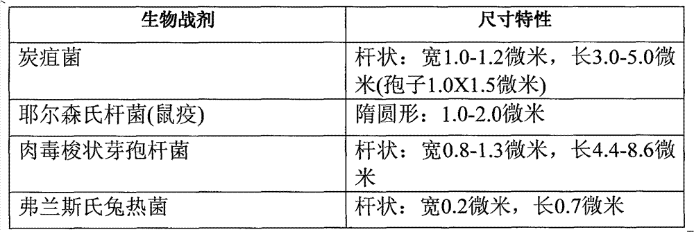
环境空气中自然存在的大小约介于1至7微米的流体悬浮颗粒极微量且具有恒定浓度。都会区域及突然发生的局部粉尘源的烟雾侵入粒径范围的峰值分别为0.3微米和5微米。在花季时,空气中也可能存在花粉和其它的过敏原,以及过敏原颗粒的大小介于约5至50微米之间。因此,这些天然的悬浮颗粒中仅有少数落在生化战剂的粒径范围内(1至7微米)。此外,虽然霉菌具有约1至5微米的粒径,但是在任何特定区域内的霉菌颗粒数通常不会突然地改变。因此根据第四示例性实施方式的该检测系统301的设计可检测在此特定尺寸范围内的粒径,并以0.5微米之间隔来产生代表该粒径检测范围的输出。任何颗粒尺寸介于1至7微米内的悬浮颗粒数目的突然及区域性增加最可能为刻意地释出侵略性生物战剂或病原体。该系统可设定为检测和储存所欲颗粒大小范围内的颗粒天然背景浓度,然后利用此背景浓度作为其后输出柱状图的比较浓度,以在检测到颗粒突然增加的情形时启动该警报器。图8的粒径分布柱状图显示一可能的危险状态,在图中,介于1至7微米粒径范围内所检测的颗粒数目已远超过正常值。 Fluid-suspended particles naturally present in ambient air in minute and constant concentrations ranging in size from approximately 1 to 7 microns. The peaks of the smoke intrusion particle size ranges in metropolitan areas and sudden local dust sources are 0.3 microns and 5 microns respectively. During flowering season, pollen and other allergens may also be present in the air, and the size of the allergen particles ranges from about 5 to 50 microns. Therefore, only a small number of these natural suspended particles fall within the particle size range (1 to 7 microns) of a BW agent. Furthermore, although mold has a particle size of about 1 to 5 microns, the number of mold particles in any given area usually does not change abruptly. The detection system 301 according to the fourth exemplary embodiment is therefore designed to detect particle sizes within this particular size range and generate an output representative of the particle size detection range at intervals of 0.5 microns. Sudden and localized increases in the number of suspended particles of any size between 1 and 7 microns are most likely the deliberate release of aggressive biological warfare agents or pathogens. The system can be set to detect and store the natural background concentration of particles in the desired particle size range, and then use this background concentration as a comparison concentration for subsequent output histograms to activate the alarm when a sudden increase in particles is detected . The histogram of particle size distribution in Fig. 8 shows a possible dangerous state, in which the number of detected particles in the particle size range of 1 to 7 microns has far exceeded the normal value. the
虽然如上所述的颗粒检测系统无法分辨特定的颗粒,但由于在正常都市空气环境中,此目标范围内的悬浮颗粒通常相对较为稀少,故其可作为警告悬浮生物战剂攻击的一种敏感和具成本效益的方法。大小落在此范围内的颗粒可能侵入人类肺部而产生可能的伤害或甚至造成吸入者死亡。该警报装置342可对 附近民众提出警告而立刻进行疏散以减少暴露于该毒剂中的危险。
Although the particle detection system described above cannot distinguish specific particles, since the suspended particles in this target area are usually relatively rare in normal urban air environment, it can be used as a sensitive and effective method to warn of the attack of suspended biological warfare agents. cost-effective method. Particles falling within this size range may penetrate the human lungs causing possible injury or even death to the inhaler. The
该检测系统301也可用于检测工厂中有害粉尘的危险程度。例如,有害石绵纤维的大小约为5微米,其通常具有约5微米或更长的长度以及约1-2微米的直径。若将大小介于1-5微米间的铍尘被吸入肺部时也会造成伤害。该检测系统301可置于含石绵的建筑物内,或当建筑工人在此类建筑物内工作时,以便在检测到1至5微米范围内的异常峰值时产生警告信号,其表示空气中存在危险量的石绵纤维。同样,该检测系统301可置于制造含铍零件的工人的附近,以便于当介于1至5微米的颗粒数目突然增加时产生警告信号,其表示铍尘可能已达到危险的浓度。该检测系统301于正常情况下虽然无法分辨在该相同粒径范围内的石绵或铍尘,但是当工作于石绵或铍环境下时若此粒径范围内的颗粒突然增加应听从可能存在危险状态的指示立刻疏散该区域之后再作进一步的检测。 The detection system 301 can also be used to detect the dangerous degree of harmful dust in the factory. For example, hazardous asbestos fibers are about 5 microns in size, typically have a length of about 5 microns or more and a diameter of about 1-2 microns. Beryllium dust, which is between 1-5 microns in size, can also cause harm when inhaled into the lungs. The detection system 301 can be placed in buildings containing asbestos, or when construction workers are working in such buildings, so as to generate a warning signal when abnormal peaks in the range of 1 to 5 microns are detected, indicating Asbestos fibers are present in hazardous quantities. Likewise, the detection system 301 can be placed in the vicinity of workers making beryllium-containing parts to generate a warning signal when there is a sudden increase in the number of particles between 1 and 5 microns, which indicates that beryllium dust may have reached a dangerous concentration. Although the detection system 301 cannot distinguish asbestos or beryllium dust in the same particle size range under normal circumstances, if the particles in this particle size range suddenly increase when working in an asbestos or beryllium environment, you should listen to the possible existence of Indication of Hazardous Condition Immediately evacuate the area prior to further testing. the
同样,该检测系统301也可被用于无菌制造工厂,例如食品或医药制造厂,以连续监控微生物的溢出,而可在第一时间采取紧急的补救措施。同样,该检测系统301已被用作一持续监控系统,以便根据无尘室的要求,提醒工厂管理人有关微生物检测的历史数据和趋势信息。 Similarly, the detection system 301 can also be used in aseptic manufacturing plants, such as food or pharmaceutical manufacturing plants, to continuously monitor the spillage of microorganisms, and take emergency remedial measures at the first time. Also, the detection system 301 has been used as a continuous monitoring system to alert plant managers of historical data and trending information on microbial detection as required by the cleanroom. the
在上述检测系统301内,使用两阶段的检测及鉴别过程,该具有光学系统310的系统首先将落在该包含目标粒径范围的预设角度范围以外的散射光除去。接着,根据脉波高度来识别所测得输出脉冲,计算各高度的脉波数目并转换成例如0.2微米内的粒径,并将结果显示为柱状图,并且每隔适当的时间间隔便产生一新的柱状图以说明颗粒分布情形的改变。然而,除了以粒径分布柱状图显示之外,该检测系统301的光学部分或可配置成仅将相当于1至7微米粒径范围的散射光信号部分引导至检测器14,以及检测系统301的其余部分则配置成当检测系统301的输出若超过一预设阀值时会发出一警告信号。此将提供较不准确的输出,并且无法判断在该检测大小范围内的粒径识别,但若有相当于已知悬浮病原体、过敏原或如铍尘或石绵等其它有害颗粒的大小范围内的颗粒数目不寻常大量增加时,仍能产生一相对准确的警报。图3的光学系统301仅需改良成可提供较大的中央阻挡区,以阻挡尺寸大于约7微米的颗粒的散射光,并且该输出电路被改良成可在颗粒检测器366的输出端提供一阀值鉴别器,以在该检测信号若高于所选择的阀值时,从该鉴别器提供一输出信号来 启动一警报器。
In the detection system 301 described above, a two-stage detection and identification process is used. The system with the
本发明的病原体检测器可用于各种用途。例如,病原体检测器可实施成现场人员使用的电池供电式可携、手持检测器。在此情况下,其外壳可容纳光学设备和依尺寸范围来计算颗粒的电路,以及具有用以显示各粒径的目前颗粒计数的显示器,如一LED显示器。其也可包含一传输器,以传送无线信号至一基地台。其也可包含一声音警报器及一用以提示激光电力不足的警示灯。也可提供用于辨公大楼等建筑物内的独立式、桌上型仪器。此独立式、桌上型仪器类似用于现场的机型,但其经由一AC/DC转换器而使用墙壁上的标准电源插座来供电。在后者的情况,该检测器可提供对辨公桌上被生物战剂所污染的信件或包裹的保护。 The pathogen detector of the present invention can be used in various applications. For example, the pathogen detector may be implemented as a battery powered portable, hand-held detector for use by field personnel. In this case, the housing can house the optics and circuitry to count particles by size range, as well as a display, such as an LED display, to show the current particle count for each particle size. It may also include a transmitter for transmitting wireless signals to a base station. It may also include an audible siren and a warning light for low power to the laser. Stand-alone and table-top instruments used in buildings such as public buildings can also be provided. This stand-alone, table-top instrument is similar to the model used in the field, but it is powered using a standard wall outlet through an AC/DC converter. In the latter case, the detector could provide protection against letters or packages on desks contaminated with biological warfare agents. the
该检测器也可作为一多功能建筑物保全系统中的一部分,其包括置于不同房间内并连接至中央监控计算机或控制台的多台检测器。可程序化该控制台以监控各房间的颗粒数,及分析任何病原体大小颗粒的异常增加来源,以及预测病原体颗粒在该建筑物内的可能散播模式。该检测器可利用实体线路相连接,或具有无线电传送器以便将数据传送至中央控制台,以分析任何生物战剂颗粒增加的来源以及任何生物战剂烟尘的可能扩散模式。 The detector can also be used as part of a multifunctional building security system, which includes multiple detectors placed in different rooms and connected to a central monitoring computer or console. The console can be programmed to monitor particle counts in each room, and analyze the source of any abnormal increase in pathogen-sized particles, and predict the likely spread pattern of pathogen particles within the building. The detectors may be physically wired, or have radio transmitters to transmit data to a central control station for analysis of the source of any BW particle build-up and possible spread patterns of any BW aerosol. the
揭示于此处的流体悬浮颗粒检测器也可用于监控无尘室,以防可能的污染和/或材料损失。 The fluid aerosol detectors disclosed herein can also be used to monitor clean rooms for possible contamination and/or material loss. the
较大范围地利用检测系统301时,仅在符合下列两种情况之下启动该警报装置342:(1)当检测到在预设粒径范围(约1至约7纳米)内的气悬颗粒数目突然增加时;以及(2)当利用如下述的激光诱发荧光检测到生物有机体、生物战剂或有机物质时。
When the detection system 301 is widely used, the
粒径传感器本身具有环境颗粒误报的缺点。若该病原检测系统301为结合有利用紫外线诱发荧光传感器以分辨生物性或非生生物性颗粒的颗粒尺寸测定能力的生物有机体或生物战剂辨认检测器时,可进一步减少这些误报的情形。本发明的检测系统301包括一第一光学检测器326和一具有激光诱发荧光传感器以检测生物有机体的代谢物或如生物战剂等生物制剂的第二光学检测器376。更明确而言,该光学系统310包括一可在约270至约410纳米波长,较佳为在约350至约410纳米下操作的激发光源312。当生物制剂含有三种主要代谢物:色胺酸,其通常约270纳米(在约220至约300纳米范围内)下发出 荧光;烟酰胺腺嘌呤双核苷(NADH),其通常在约340纳米(从约300至约400纳米范围)下发出荧光;以及核黄素(riboflavin),其通常在约400纳米(从约320至约420纳米范围)下发出荧光的情况下,选择约270至约410纳米波长。然而,该激发光源312较佳为具有约350至约410纳米的波长。此波长确保可激发生物制剂内上述三种主要代谢物中的两种,即生物制剂NADH和核黄素,但不激发其它干扰物质,如柴油引擎废气和其它如粉尘或爽身粉等惰性颗粒。因此,在第四实施例中,使激发光源312的明确选择的波长范围能够保留激发NADH和核黄素的荧光的能力(上述激发色胺酸的能力),同时不激发其它如柴油废气等干扰物。此步骤可减少因柴油废气(可被如266纳米的光线等短UV波长所激发)而产生的误报。
Particle size sensors themselves have the disadvantage of false positives for ambient particles. These false positives can be further reduced if the pathogen detection system 301 is a biological organism or biological warfare agent identification detector combined with a particle size measurement capability using a UV-induced fluorescence sensor to distinguish biological or abiotic particles. The detection system 301 of the present invention includes a first
图9显示上述四种代谢物的荧光光谱。光谱分析,特别该利用不同激发波长的光谱分析,可探测微生物的组成成分,并可将所产生的数据用于微生物的检测和分类上。 Figure 9 shows the fluorescence spectra of the above four metabolites. Spectral analysis, especially using different excitation wavelengths, can detect the composition of microorganisms, and the data generated can be used for the detection and classification of microorganisms. the
该光学检测器326、376的输出端分别连接至除法器330A、330C,进而经由放大器330A、330C和模拟数字转换器334连接至控制显示装置338,从而连接至警报装置342。
The output ends of the
必需强调的是,上述本发明实施例,特别指任何“较佳”实施例为可行的实施例,仅为帮助更清础了解本发明的原理而作的说明。上述本发明的实施例可进行许多不同的改良,但其实质上仍未偏离本发明的精神和原理。全部此类的改良和变化均属于本文公开内容及本发明范围内,并且受到下列权利要求书的保护。 It must be emphasized that the above-mentioned embodiments of the present invention, especially referring to any "preferable" embodiments as feasible embodiments, are only illustrations for helping to understand the principle of the present invention more clearly. The above embodiments of the present invention can be modified in many different ways without departing from the spirit and principle of the present invention. All such improvements and changes are within the scope of this disclosure and the present invention, and are protected by the following claims. the
Claims (9)
Applications Claiming Priority (3)
| Application Number | Priority Date | Filing Date | Title |
|---|---|---|---|
| US70000805P | 2005-07-15 | 2005-07-15 | |
| US60/700,008 | 2005-07-15 | ||
| PCT/US2006/027638 WO2007011854A2 (en) | 2005-07-15 | 2006-07-17 | Pathogen and particle detector system and method |
Publications (2)
| Publication Number | Publication Date |
|---|---|
| CN101223560A CN101223560A (en) | 2008-07-16 |
| CN101223560B true CN101223560B (en) | 2012-12-12 |
Family
ID=37669459
Family Applications (1)
| Application Number | Title | Priority Date | Filing Date |
|---|---|---|---|
| CN2006800259429A Expired - Fee Related CN101223560B (en) | 2005-07-15 | 2006-07-17 | Pathogen and particle detector system and method |
Country Status (6)
| Country | Link |
|---|---|
| US (1) | US7738099B2 (en) |
| EP (1) | EP1907818A4 (en) |
| JP (1) | JP5112312B2 (en) |
| KR (1) | KR101283071B1 (en) |
| CN (1) | CN101223560B (en) |
| WO (1) | WO2007011854A2 (en) |
Families Citing this family (99)
| Publication number | Priority date | Publication date | Assignee | Title |
|---|---|---|---|---|
| EP1784912A4 (en) * | 2004-07-30 | 2012-03-14 | Biovigilant Systems Inc | METHOD AND SYSTEM FOR DETECTING PATHOGENS AND PARTICLES |
| AU2006347212B8 (en) * | 2005-07-21 | 2011-09-01 | Respiratory Management Technology | A particle counting and DNA uptake system and method for detection, assessment and further analysis of threats due to nebulized biological agents |
| US7996188B2 (en) | 2005-08-22 | 2011-08-09 | Accuri Cytometers, Inc. | User interface for a flow cytometer system |
| US8243272B2 (en) * | 2005-09-19 | 2012-08-14 | Jmar Llc | Systems and methods for detecting normal levels of bacteria in water using a multiple angle light scattering (MALS) instrument |
| US8303894B2 (en) | 2005-10-13 | 2012-11-06 | Accuri Cytometers, Inc. | Detection and fluidic system of a flow cytometer |
| US8017402B2 (en) | 2006-03-08 | 2011-09-13 | Accuri Cytometers, Inc. | Fluidic system for a flow cytometer |
| US8031340B2 (en) * | 2006-02-22 | 2011-10-04 | Accuri Cytometers, Inc. | Optical system for a flow cytometer |
| US8283177B2 (en) | 2006-03-08 | 2012-10-09 | Accuri Cytometers, Inc. | Fluidic system with washing capabilities for a flow cytometer |
| US7780916B2 (en) | 2006-03-08 | 2010-08-24 | Accuri Cytometers, Inc. | Flow cytometer system with unclogging feature |
| WO2008105893A2 (en) | 2006-06-27 | 2008-09-04 | Biovigilant Systems, Inc. | Pathogen detection by simultaneous size/fluorescence measurement |
| US8715573B2 (en) | 2006-10-13 | 2014-05-06 | Accuri Cytometers, Inc. | Fluidic system for a flow cytometer with temporal processing |
| WO2008058217A2 (en) * | 2006-11-07 | 2008-05-15 | Accuri Instruments Inc. | Flow cell for a flow cytometer system |
| US7739060B2 (en) * | 2006-12-22 | 2010-06-15 | Accuri Cytometers, Inc. | Detection system and user interface for a flow cytometer system |
| US8821799B2 (en) | 2007-01-26 | 2014-09-02 | Palo Alto Research Center Incorporated | Method and system implementing spatially modulated excitation or emission for particle characterization with enhanced sensitivity |
| US9164037B2 (en) * | 2007-01-26 | 2015-10-20 | Palo Alto Research Center Incorporated | Method and system for evaluation of signals received from spatially modulated excitation and emission to accurately determine particle positions and distances |
| DE102007031244B3 (en) * | 2007-07-05 | 2009-01-02 | Fraunhofer-Gesellschaft zur Förderung der angewandten Forschung e.V. | Apparatus and method for performing static and dynamic scattered light measurements in small volumes |
| US7672813B2 (en) * | 2007-12-03 | 2010-03-02 | Smiths Detection Inc. | Mixed statistical and numerical model for sensor array detection and classification |
| US8432541B2 (en) * | 2007-12-17 | 2013-04-30 | Accuri Cytometers, Inc. | Optical system for a flow cytometer with an interrogation zone |
| US8629981B2 (en) | 2008-02-01 | 2014-01-14 | Palo Alto Research Center Incorporated | Analyzers with time variation based on color-coded spatial modulation |
| JP5693973B2 (en) * | 2008-03-03 | 2015-04-01 | コーニンクレッカ フィリップス エヌ ヴェ | High resolution classification |
| DE102008029700A1 (en) * | 2008-06-24 | 2010-01-14 | Palas Gmbh Partikel- Und Lasermesstechnik | Method for determining the penetration of test particles into a measuring range |
| JP5190700B2 (en) * | 2008-11-14 | 2013-04-24 | 株式会社Ihi | Gas component concentration measuring device |
| US9562855B1 (en) | 2009-12-03 | 2017-02-07 | The Arizona Board Of Regents On Behalf Of The University Of Arizona | Devices and methods for detection of microorganisms via MIE scattering |
| WO2010065669A1 (en) * | 2008-12-03 | 2010-06-10 | Jeong-Yeol Yoon | Methods and microfluidic devices for single cell detection of escherichia coli |
| US9678005B1 (en) * | 2008-12-03 | 2017-06-13 | Arizona Board Of Regents On Behalf Of The University Of Arizona | Devices and methods for detection of microorganisms |
| US8507279B2 (en) | 2009-06-02 | 2013-08-13 | Accuri Cytometers, Inc. | System and method of verification of a prepared sample for a flow cytometer |
| US8779387B2 (en) | 2010-02-23 | 2014-07-15 | Accuri Cytometers, Inc. | Method and system for detecting fluorochromes in a flow cytometer |
| FI20105645A0 (en) * | 2010-06-07 | 2010-06-07 | Environics Oy | APPARATUS AND METHOD FOR DETECTING BIOLOGICAL MATERIAL |
| US9551600B2 (en) | 2010-06-14 | 2017-01-24 | Accuri Cytometers, Inc. | System and method for creating a flow cytometer network |
| JP2012026837A (en) * | 2010-07-22 | 2012-02-09 | Sony Corp | Fine particle measurement instrument |
| JP5681600B2 (en) * | 2010-09-24 | 2015-03-11 | 新日本空調株式会社 | Biological particle evaluation apparatus and biological particle evaluation method |
| ES2897531T3 (en) | 2010-10-25 | 2022-03-01 | Accuri Cytometers Inc | Systems and user interface for collecting a data set in a flow cytometer |
| KR20120071453A (en) * | 2010-12-23 | 2012-07-03 | 삼성전자주식회사 | Apparatus for detection of microorganism |
| JP2012199359A (en) * | 2011-03-22 | 2012-10-18 | Sony Corp | Laser irradiation device and microparticle measuring apparatus |
| JP5787390B2 (en) | 2011-04-06 | 2015-09-30 | インスタント バイオスキャン, エルエルシー | Microorganism detection apparatus and method |
| WO2012167894A1 (en) * | 2011-06-06 | 2012-12-13 | Sicpa Holding Sa | In-line decay-time scanner |
| TWI435080B (en) * | 2011-06-09 | 2014-04-21 | Univ Nat Pingtung Sci & Tech | Cell or particle detecting device |
| US9029800B2 (en) * | 2011-08-09 | 2015-05-12 | Palo Alto Research Center Incorporated | Compact analyzer with spatial modulation and multiple intensity modulated excitation sources |
| CA2853093C (en) * | 2011-10-21 | 2020-01-14 | Acea Biosciences, Inc. | System and method for detecting multiple-excitation-induced light in a flow channel |
| JP6238272B2 (en) * | 2011-12-05 | 2017-11-29 | リオン株式会社 | Biological particle counter and biological particle counting method |
| EP2790008B1 (en) * | 2011-12-05 | 2017-11-15 | Rion Co., Ltd. | Biological particle counter, biological particle counting method, dialysate monitoring system, and water purification monitoring system |
| JP5965151B2 (en) * | 2012-01-16 | 2016-08-03 | リオン株式会社 | Bioparticle counter for dialysis, bioparticle counting method for dialysis, and dialysate monitoring system |
| JP2013148391A (en) * | 2012-01-17 | 2013-08-01 | Rion Co Ltd | Viable particle counter for purified water, viable particle counting method for purified water, and purified water monitoring system |
| CN102590168A (en) * | 2012-02-16 | 2012-07-18 | 无锡迈通科学仪器有限公司 | Light emitting diode-based fluorescent microorganism detector |
| CN104813160A (en) * | 2012-06-01 | 2015-07-29 | 威瑞泰得有限公司 | Real-time optical detection of bacteria |
| JP6075979B2 (en) * | 2012-06-27 | 2017-02-08 | リオン株式会社 | Particle counting system |
| KR101411428B1 (en) * | 2012-07-12 | 2014-06-24 | 한국과학기술원 | Condensing type portable fluorescence detection system |
| JPWO2014017430A1 (en) * | 2012-07-25 | 2016-07-11 | 株式会社村田製作所 | Measuring method of measured object |
| JP5665811B2 (en) | 2012-08-02 | 2015-02-04 | 国立大学法人九州大学 | Light-induced fluorescence measuring instrument |
| US20140049768A1 (en) * | 2012-08-16 | 2014-02-20 | Behrokh B. Sadri | HIgh-throughput single laser wave mixing detection methods and apparatus |
| US8943883B2 (en) | 2012-09-14 | 2015-02-03 | HGST Netherlands B.V. | Apparatus for counting microparticles using a gas reservoir to increase stability of air pressure |
| JP2014062822A (en) * | 2012-09-21 | 2014-04-10 | Sony Corp | Fine particle analyzer and fine particle analyzing method |
| JP6126400B2 (en) | 2013-02-08 | 2017-05-10 | リオン株式会社 | Biological particle counting system and biological particle counting method |
| EP2965064A4 (en) * | 2013-03-05 | 2016-11-30 | Smiths Detection Inc | Transmission raman sample analysis |
| US9354178B2 (en) | 2013-03-05 | 2016-05-31 | Smiths Detection Inc. | Transmission raman sample analysis |
| US9291564B2 (en) * | 2013-04-05 | 2016-03-22 | Datacolor Holding Ag | Method and apparatus for aligning measured spectral radiance factors among different instruments |
| WO2015077349A2 (en) | 2013-11-19 | 2015-05-28 | Acea Biosciences, Inc. | Optical engine for flow cytometer, flow cytometer system and methods of use |
| US10261080B2 (en) | 2013-11-19 | 2019-04-16 | Acea Biosciences, Inc. | Optical detection system for flow cytometer, flow cytometer system and methods of use |
| JP6191426B2 (en) * | 2013-12-05 | 2017-09-06 | 株式会社島津製作所 | Particle size distribution measuring device, display processing device used therefor, and particle size distribution measuring method |
| KR101926377B1 (en) * | 2013-12-13 | 2018-12-10 | 코웨이 주식회사 | Air cleaner having biosensor |
| EP2905607A1 (en) * | 2014-02-07 | 2015-08-12 | Nxp B.V. | Analyte detection methods and devices |
| CN103969162B (en) * | 2014-05-09 | 2016-08-31 | 山东科技大学 | The method and device that a kind of mine coal dust concentration based on data fusion is measured |
| US9869628B2 (en) | 2014-06-25 | 2018-01-16 | Acea Biosciences, Inc. | Methods of collecting cells from multi-well plates for use in flow cytometry |
| WO2016161292A1 (en) * | 2015-04-02 | 2016-10-06 | Particle Measuring Systems, Inc. | Laser noise detection and mitigation in particle counting instruments |
| CN105115904B (en) * | 2015-09-30 | 2018-11-09 | 浙江大学 | The unburned carbon in flue dust on-line measurement device pulsed based on infrared external reflection and light |
| CN105675455B (en) * | 2016-01-08 | 2018-09-11 | 珠海欧美克仪器有限公司 | A kind of method and device reducing stochastic system noise in Particle Size Analyzer |
| CN105671123B (en) * | 2016-01-19 | 2018-11-20 | 西南交通大学 | The method of counting of bacterium in a kind of liquid |
| CN105572020B (en) * | 2016-01-19 | 2018-05-22 | 西南交通大学 | A kind of nano-particle method of counting |
| EP4545936A3 (en) * | 2016-03-17 | 2025-07-16 | Becton, Dickinson and Company | Cell sorting using a high throughput fluorescence flow cytometer |
| KR101966492B1 (en) | 2016-03-25 | 2019-04-05 | 현대자동차주식회사 | Dust sensor for vehicle |
| CN105973769A (en) * | 2016-04-28 | 2016-09-28 | 清华大学深圳研究生院 | Device and method for measurement of size of suspended submicron particulate matter |
| KR101851059B1 (en) * | 2016-05-09 | 2018-06-01 | 한국산업기술시험원 | System for monitoring particle in the filtered water |
| CN105865997A (en) * | 2016-06-07 | 2016-08-17 | 中国科学院合肥物质科学研究院 | Atmospheric raise dust concentration measuring device and method based on forward scattering principle |
| EP3309536A1 (en) * | 2016-10-11 | 2018-04-18 | Malvern Panalytical Limited | Particle characterisation instrument |
| DK3546924T3 (en) * | 2016-11-22 | 2022-05-09 | Rion Co | MICROBIAL PARTICULATE COUNTING SYSTEM AND MICROBIAL PARTICULATE COUNTING METHOD |
| KR102252999B1 (en) | 2016-12-07 | 2021-05-18 | 한국전자기술연구원 | Apparatus and method for detecting biological particles using ultraviolet light source |
| CN106645673B (en) * | 2017-02-28 | 2018-05-18 | 山东省科学院生物研究所 | A kind of device and its method of work using zebra fish evaluation compound acute toxicity |
| CN107014491B (en) * | 2017-05-27 | 2018-04-10 | 西安电子科技大学 | Spectral measurement system and method based on scattering principle |
| US20200400544A1 (en) * | 2017-12-15 | 2020-12-24 | Ams International Ag | Integrated filter-based particulate matter sensors |
| US10274410B1 (en) * | 2018-01-23 | 2019-04-30 | Cbrn International, Ltd. | Bioaerosol particle detector |
| CN108693142B (en) * | 2018-06-11 | 2020-10-30 | 重庆大学 | A PM2.5 Detection Method Based on Optical Scattering Principle |
| US11137331B2 (en) * | 2018-08-21 | 2021-10-05 | Viavi Solutions Inc. | Multispectral sensor based alert condition detector |
| WO2020106036A1 (en) | 2018-11-19 | 2020-05-28 | Samsung Electronics Co., Ltd. | Multimodal dust sensor |
| KR102030307B1 (en) * | 2019-01-04 | 2019-10-08 | 아이센테크주식회사 | Light sensing device having filter structure and explosives detection system including the same |
| EP3924716A1 (en) * | 2019-02-12 | 2021-12-22 | Christoph Langhammer | System and method for detecting a presence of a particle in a fluid |
| KR102749855B1 (en) * | 2019-07-24 | 2025-01-02 | 삼성전자주식회사 | Particulate matter measurement apparatus and method |
| CN110927025B (en) * | 2019-12-05 | 2023-03-10 | 北京华泰诺安探测技术有限公司 | Aerosol particle monitoring equipment |
| US20240319063A1 (en) | 2020-04-26 | 2024-09-26 | Viktor TOMASOV | Airborne bacteria detection system |
| US12535357B2 (en) * | 2020-08-03 | 2026-01-27 | Siemens Healthcare Diagnostics Inc. | Absorbance spectroscopy analyzer and method of use |
| CN112255206B (en) * | 2020-09-11 | 2023-06-09 | 中国科学院苏州生物医学工程技术研究所 | Spectroscopic detection unit, particle detection device and method |
| KR102482713B1 (en) * | 2020-09-25 | 2022-12-29 | 배관수 | Fine dust measuring apparatus |
| US12066368B2 (en) * | 2020-10-15 | 2024-08-20 | Robert R. Alfano | Compact optical virus detection analyzer of nano- and micro-size bio particles using light scattering and fluorescence |
| WO2022115712A1 (en) * | 2020-11-30 | 2022-06-02 | H2Ok Innovations Inc. | Methods and systems for monitoring fluids |
| WO2022167795A1 (en) * | 2021-02-03 | 2022-08-11 | Silver Joshua D | Viral load tester and applications thereof |
| CN113030058A (en) * | 2021-04-23 | 2021-06-25 | 中国计量大学 | Device and method for detecting AFB1 in beer based on two-photon fluorescence |
| CN113552042A (en) * | 2021-07-21 | 2021-10-26 | 乐金显示光电科技(中国)有限公司 | A kind of wet etching equipment and management method thereof |
| CN114480111A (en) * | 2022-02-15 | 2022-05-13 | 深圳阿斯克医疗有限公司 | Real-time fluorescence quantitative PCR instrument |
| CN118730993B (en) * | 2024-08-07 | 2025-04-29 | 中国科学院大气物理研究所 | Trace type fluorescent aerosol detection module based on dual-band light source |
| CN118758829B (en) * | 2024-09-03 | 2024-12-10 | 昆明理工大学 | Top-blown furnace dust concentration detection method based on combination of light absorption method and light reflection method |
Citations (1)
| Publication number | Priority date | Publication date | Assignee | Title |
|---|---|---|---|---|
| CN1424572A (en) * | 2003-01-10 | 2003-06-18 | 东南大学 | Laser light scattering dust concentration on line measuring method |
Family Cites Families (153)
| Publication number | Priority date | Publication date | Assignee | Title |
|---|---|---|---|---|
| US3457407A (en) * | 1966-07-27 | 1969-07-22 | Us Navy | Apparatus for quantitatively detecting foreign particles present in atmospheric air |
| NL173679C (en) | 1970-01-29 | 1984-02-16 | Beckman Instruments Inc | PHOTOMETER FOR MEASURING THE TOTAL RADIANT ENERGY DISTRIBUTED BY A TEST QUANTITY UNDER A SELECTED ANGLE. |
| BE793185A (en) * | 1971-12-23 | 1973-04-16 | Atomic Energy Commission | APPARATUS FOR QUICKLY ANALYZING AND SORTING PARTICLES SUCH AS BIOLOGICAL CELLS |
| US3867640A (en) * | 1972-03-09 | 1975-02-18 | Levy Co Edward C | Dust sampling system |
| US3826364A (en) * | 1972-05-22 | 1974-07-30 | Univ Leland Stanford Junior | Particle sorting method and apparatus |
| US3845480A (en) | 1973-02-20 | 1974-10-29 | Air Technologies Inc | Particulate detector system |
| US3850525A (en) | 1973-07-09 | 1974-11-26 | Beckman Instruments Inc | Simultaneous multiple measurements in laser photometers |
| CH592933A5 (en) | 1976-04-05 | 1977-11-15 | Cerberus Ag | |
| US4355897A (en) | 1977-12-27 | 1982-10-26 | Beckman Instruments, Inc. | Near-simultaneous measurements at forward and back scatter angles in light scattering photometers |
| US4251733A (en) * | 1978-06-29 | 1981-02-17 | Hirleman Jr Edwin D | Technique for simultaneous particle size and velocity measurement |
| US4226533A (en) | 1978-09-11 | 1980-10-07 | General Electric Company | Optical particle detector |
| GB2040443B (en) * | 1978-12-07 | 1983-01-12 | English Electric Co Ltd | Optical particle size analyser |
| FR2445961A1 (en) | 1979-01-02 | 1980-08-01 | Coulter Electronics | METHOD AND DEVICE WITH FLOW CHAMBER READITING RADIANT ENERGY |
| US4286876A (en) * | 1979-01-02 | 1981-09-01 | Coulter Electronics, Inc. | Apparatus and method for measuring scattering of light in particle detection systems |
| US4599307A (en) * | 1983-07-18 | 1986-07-08 | Becton, Dickinson And Company | Method for elimination of selected cell populations in analytic cytology |
| US4583859A (en) * | 1984-03-30 | 1986-04-22 | The Babcock & Wilcox Company | Filter cleaning system for opacity monitor |
| US4727020A (en) * | 1985-02-25 | 1988-02-23 | Becton, Dickinson And Company | Method for analysis of subpopulations of blood cells |
| US4633714A (en) | 1985-08-13 | 1987-01-06 | University Of Arkansas | Aerosol particle charge and size analyzer |
| GB8523747D0 (en) * | 1985-09-26 | 1985-10-30 | Vg Instr Group | Fibre size monitor |
| US4728190A (en) * | 1985-10-15 | 1988-03-01 | Particle Measuring Systems, Inc. | Device and method for optically detecting particles in a fluid |
| US4830494A (en) * | 1986-07-10 | 1989-05-16 | Kowa Company Ltd. | Method and apparatus for measuring particles in a fluid |
| JPS6319536A (en) * | 1986-07-14 | 1988-01-27 | Hitachi Ltd | Detector for fine particle in solution |
| DE3628072A1 (en) * | 1986-08-19 | 1987-04-09 | Fruengel Frank Dr Ing | AEROSOL AND FINE DUST MEASURING DEVICE ACCORDING TO THE SPREADLIGHT PRINCIPLE |
| JP2733766B2 (en) * | 1986-11-14 | 1998-03-30 | クエニコ、アクチエボラク | Piezo pump |
| KR970007077B1 (en) * | 1987-03-13 | 1997-05-02 | 코울터 일렉트로닉스 인커퍼레이티드 | Multi-Partial Identification Method Using Light Scattering Technique |
| JP2529966B2 (en) * | 1987-03-28 | 1996-09-04 | 株式会社東芝 | Particle size measuring device |
| US4849340A (en) * | 1987-04-03 | 1989-07-18 | Cardiovascular Diagnostics, Inc. | Reaction system element and method for performing prothrombin time assay |
| US5123731A (en) * | 1988-02-01 | 1992-06-23 | Canon Kabushiki Kaisha | Particle measuring device |
| JP2674704B2 (en) * | 1988-06-07 | 1997-11-12 | 東亜医用電子株式会社 | Two-dimensional distribution fractionation method |
| JP2674705B2 (en) * | 1988-06-10 | 1997-11-12 | 東亜医用電子株式会社 | One-dimensional distribution fractionation method |
| US5408307A (en) * | 1988-07-11 | 1995-04-18 | Omron Tateisi Electronics Co. | Cell analyzer |
| JPH02170053A (en) | 1988-12-23 | 1990-06-29 | Meiji Seika Kaisha Ltd | Microorganism detection method and device |
| US5056918A (en) | 1989-03-03 | 1991-10-15 | Coulter Electronics Of New England, Inc. | Method and apparatus for particle size analysis |
| JP2756298B2 (en) * | 1989-03-18 | 1998-05-25 | キヤノン株式会社 | Sample test equipment |
| US5760900A (en) * | 1989-03-18 | 1998-06-02 | Canon Kabushiki Kaisha | Method and apparatus for optically measuring specimen |
| US5101113A (en) * | 1989-05-16 | 1992-03-31 | Arizona Board Of Regents | Ensemble scattering particle sizing system with axial spatial resolution |
| DE3917571A1 (en) * | 1989-05-30 | 1990-12-06 | Sick Optik Elektronik Erwin | METHOD FOR MEASURING THE INTENSITY OF SPARKLIGHT AND MEASURING DEVICE FOR CARRYING OUT THE METHOD |
| US5121988A (en) * | 1989-10-04 | 1992-06-16 | Tsi Incorporated | Single particle detector method and apparatus utilizing light extinction within a sheet of light |
| EP0422616B1 (en) * | 1989-10-11 | 1996-02-07 | Canon Kabushiki Kaisha | Apparatus for and method of fractionating particle in particle-suspended liquid in conformity with the properties thereof |
| US5085500A (en) * | 1989-11-28 | 1992-02-04 | Tsi Incorporated | Non-imaging laser particle counter |
| JP2815435B2 (en) | 1989-12-22 | 1998-10-27 | 株式会社日立製作所 | Particle analyzer and blood cell counter |
| US5083865A (en) * | 1990-05-11 | 1992-01-28 | Applied Materials, Inc. | Particle monitor system and method |
| JP2899360B2 (en) | 1990-05-21 | 1999-06-02 | 興和株式会社 | Method and apparatus for measuring particles in fluid |
| GB9014015D0 (en) * | 1990-06-23 | 1990-08-15 | Dennis Peter N J | Improvements in or relating to smoke detectors |
| JPH04122042A (en) | 1990-09-12 | 1992-04-22 | Nikon Corp | Foreign matter inspection device |
| US5132548A (en) * | 1990-09-14 | 1992-07-21 | High Yield Technology | High sensitivity, large detection area particle sensor for vacuum applications |
| US5266798A (en) | 1990-09-14 | 1993-11-30 | High Yield Technology | High sensitivity, large detection area particle sensor for vacuum applications |
| US5286452A (en) * | 1991-05-20 | 1994-02-15 | Sienna Biotech, Inc. | Simultaneous multiple assays |
| US5262696A (en) * | 1991-07-05 | 1993-11-16 | Rockwell International Corporation | Biaxial transducer |
| JP2507483Y2 (en) * | 1991-08-17 | 1996-08-14 | 株式会社堀場製作所 | Laser diffraction particle size analyzer |
| JP3145487B2 (en) | 1992-06-12 | 2001-03-12 | シスメックス株式会社 | Particle analyzer |
| US5315115A (en) * | 1992-08-10 | 1994-05-24 | Gerber Hermann E | Optical apparatus and method for sensing particulates |
| JP3215175B2 (en) | 1992-08-10 | 2001-10-02 | シスメックス株式会社 | Particle analyzer |
| US5383024A (en) * | 1992-08-12 | 1995-01-17 | Martin Marietta Energy Systems, Inc. | Optical wet steam monitor |
| US5736410A (en) * | 1992-09-14 | 1998-04-07 | Sri International | Up-converting reporters for biological and other assays using laser excitation techniques |
| US6159686A (en) | 1992-09-14 | 2000-12-12 | Sri International | Up-converting reporters for biological and other assays |
| DE69333502T2 (en) * | 1992-09-14 | 2005-04-14 | Sri International, Menlo Park | Up-converting reporter molecule for biological and other testing using laser excitation techniques |
| DE69312628T2 (en) | 1992-10-27 | 1998-02-12 | Canon Kk | Process for conveying liquids |
| US5426501A (en) * | 1993-01-06 | 1995-06-20 | Laser Sensor Technology, Inc. | Apparatus and method for particle analysis |
| US5467189A (en) | 1993-01-22 | 1995-11-14 | Venturedyne, Ltd. | Improved particle sensor and method for assaying a particle |
| US5456102A (en) | 1993-03-19 | 1995-10-10 | Moorehead; Jack | Method and apparatus for particle counting and counter calibration |
| US5448364A (en) | 1993-03-22 | 1995-09-05 | Estek Corporation | Particle detection system with reflective line-to-spot collector |
| EP0618440A1 (en) | 1993-03-29 | 1994-10-05 | International Business Machines Corporation | Apparatus and method for high-efficiency, in-situ particle detection |
| US5481357A (en) * | 1994-03-03 | 1996-01-02 | International Business Machines Corporation | Apparatus and method for high-efficiency, in-situ particle detection |
| NO932088L (en) | 1993-06-08 | 1995-01-05 | Oddbjoern Gjelsnes | Device for use in liquid flow cytometry |
| US5416580A (en) * | 1993-07-07 | 1995-05-16 | General Signal Corporation | Methods and apparatus for determining small particle size distribution utilizing multiple light beams |
| EP0746752A4 (en) * | 1993-08-19 | 2000-02-23 | Venturedyne Ltd | Particle sensor with low-pressure-drop air flow system |
| JP3328032B2 (en) * | 1993-11-04 | 2002-09-24 | シスメックス株式会社 | Particle analyzer |
| US5428964A (en) * | 1994-01-10 | 1995-07-04 | Tec-Way Air Quality Products Inc. | Control for air quality machine |
| US5561515A (en) | 1994-10-07 | 1996-10-01 | Tsi Incorporated | Apparatus for measuring particle sizes and velocities |
| JP3347495B2 (en) | 1994-11-14 | 2002-11-20 | シスメックス株式会社 | Particle analyzer |
| US6984526B2 (en) | 1995-02-08 | 2006-01-10 | University Of South Florida | Spectrophotometric method for determining the viability of a sample containing platelets |
| US5684585A (en) | 1995-09-22 | 1997-11-04 | Met One, Inc. | Optical particle counter employing a field-calibrator |
| US5953477A (en) * | 1995-11-20 | 1999-09-14 | Visionex, Inc. | Method and apparatus for improved fiber optic light management |
| US5642193A (en) * | 1996-03-08 | 1997-06-24 | Met One, Inc. | Particle counter employing a solid-state laser with an intracavity view volume |
| US5701012A (en) | 1996-03-19 | 1997-12-23 | Her Majesty The Queen In Right Of Canada, As Represented By The Minister Of National Defence | Fluorescent biological particle detection system |
| US5895922A (en) * | 1996-03-19 | 1999-04-20 | Her Majesty The Queen In Right Of Canada, As Represented By The Minister Of National Defence | Fluorescent biological particle detection system |
| US6586193B2 (en) * | 1996-04-25 | 2003-07-01 | Genicon Sciences Corporation | Analyte assay using particulate labels |
| US5646597A (en) * | 1996-07-11 | 1997-07-08 | Robert N. Hamburger | Allergen detector system and method |
| US6087947A (en) * | 1996-07-11 | 2000-07-11 | Robert N. Hamburger | Allergen detector system and method |
| JP2862077B2 (en) * | 1996-08-28 | 1999-02-24 | 株式会社島津製作所 | Particle size distribution analyzer |
| US6242264B1 (en) * | 1996-09-04 | 2001-06-05 | The Penn State Research Foundation | Self-assembled metal colloid monolayers having size and density gradients |
| JP4323571B2 (en) | 1997-01-31 | 2009-09-02 | エックスワイ, インコーポレイテッド | Optical device |
| US5986555A (en) | 1997-10-07 | 1999-11-16 | Robert N. Hamburger | Allergen detector system and method |
| US5969622A (en) | 1997-10-07 | 1999-10-19 | Robert N. Hamburger | Allergen detector system and method |
| US5995686A (en) | 1997-12-16 | 1999-11-30 | Hamburger; Robert N. | Fiber-optic sensor device and method |
| US6682500B2 (en) * | 1998-01-29 | 2004-01-27 | David Soltanpour | Synthetic muscle based diaphragm pump apparatuses |
| US6699724B1 (en) * | 1998-03-11 | 2004-03-02 | Wm. Marsh Rice University | Metal nanoshells for biosensing applications |
| US5946093A (en) * | 1998-08-19 | 1999-08-31 | Met One, Inc. | Particle detection system and method employing an upconversion laser |
| NZ510096A (en) * | 1998-08-21 | 2003-02-28 | Surromed Inc | Confocal scanning system having spot excitation scanner and light detectors |
| US7057732B2 (en) | 1999-01-25 | 2006-06-06 | Amnis Corporation | Imaging platform for nanoparticle detection applied to SPR biomolecular interaction analysis |
| US6404497B1 (en) | 1999-01-25 | 2002-06-11 | Massachusetts Institute Of Technology | Polarized light scattering spectroscopy of tissue |
| AU3157800A (en) * | 1999-02-22 | 2000-09-14 | Evotec Biosystems Ag | Utilization of supporting material in capillary electrochromatography |
| JP2001133385A (en) * | 1999-11-05 | 2001-05-18 | Shimadzu Corp | Laser diffraction / scattering particle size distribution analyzer |
| US6687395B1 (en) * | 1999-07-21 | 2004-02-03 | Surromed, Inc. | System for microvolume laser scanning cytometry |
| US7126687B2 (en) * | 1999-08-09 | 2006-10-24 | The United States Of America As Represented By The Secretary Of The Army | Method and instrumentation for determining absorption and morphology of individual airborne particles |
| US6664550B2 (en) * | 1999-08-30 | 2003-12-16 | Sandia National Laboratories | Apparatus to collect, classify, concentrate, and characterize gas-borne particles |
| US6386015B1 (en) * | 1999-08-30 | 2002-05-14 | Sandia Corporation | Apparatus to collect, classify, concentrate, and characterize gas-borne particles |
| US7317938B2 (en) * | 1999-10-08 | 2008-01-08 | Sensys Medical, Inc. | Method of adapting in-vitro models to aid in noninvasive glucose determination |
| US6677431B2 (en) | 1999-12-10 | 2004-01-13 | The Trustees Of The University Of Pennsylvania | Design, preparation, and properties of antibacterial β-peptides |
| US6530944B2 (en) * | 2000-02-08 | 2003-03-11 | Rice University | Optically-active nanoparticles for use in therapeutic and diagnostic methods |
| CA2404600A1 (en) * | 2000-03-28 | 2001-10-04 | Board Of Regents, The University Of Texas System | Methods and apparatus for diagnostic multispectral digital imaging |
| US6639674B2 (en) | 2000-03-28 | 2003-10-28 | Board Of Regents, The University Of Texas System | Methods and apparatus for polarized reflectance spectroscopy |
| US6490530B1 (en) | 2000-05-23 | 2002-12-03 | Wyatt Technology Corporation | Aerosol hazard characterization and early warning network |
| US6784981B1 (en) * | 2000-06-02 | 2004-08-31 | Idexx Laboratories, Inc. | Flow cytometry-based hematology system |
| US7630063B2 (en) * | 2000-08-02 | 2009-12-08 | Honeywell International Inc. | Miniaturized cytometer for detecting multiple species in a sample |
| CA2414926A1 (en) * | 2000-07-07 | 2002-01-17 | Corixa Corporation | Microspheres and adjuvants for dna vaccine delivery |
| WO2003106965A2 (en) * | 2001-01-10 | 2003-12-24 | S3I L.L.C. | System and method for detecting and classifying biological particles |
| US6697652B2 (en) * | 2001-01-19 | 2004-02-24 | Massachusetts Institute Of Technology | Fluorescence, reflectance and light scattering spectroscopy for measuring tissue |
| WO2002068932A2 (en) * | 2001-02-23 | 2002-09-06 | Genicon Sciences Corporation | Methods for providing extended dynamic range in analyte assays |
| US20020165456A1 (en) | 2001-03-26 | 2002-11-07 | Murat Canpolat | Estimation of the average size of white light scatterers in normal and cancerous tissue using light scattering spectrum |
| EP1395826A4 (en) * | 2001-05-17 | 2005-11-09 | Miltenyi Biotec Gmbh | Antigen binding fragments for dendritic cell subset and use thereof |
| WO2003009010A2 (en) * | 2001-07-19 | 2003-01-30 | Burstein Technologies, Inc. | Transmissive optical disc assemblies for performing physical measurements |
| US7061622B2 (en) * | 2001-08-03 | 2006-06-13 | Case Western Reserve University | Aspects of basic OCT engine technologies for high speed optical coherence tomography and light source and other improvements in optical coherence tomography |
| EP1432971A4 (en) * | 2001-09-05 | 2007-12-05 | Genicon Sciences Corp | Method and apparatus for normalization and deconvolution of assay data |
| US20030049866A1 (en) * | 2001-09-05 | 2003-03-13 | Genicon Sciences Corporation | Sample device preservation |
| US6685730B2 (en) * | 2001-09-26 | 2004-02-03 | Rice University | Optically-absorbing nanoparticles for enhanced tissue repair |
| US6876135B2 (en) * | 2001-10-05 | 2005-04-05 | Sri International | Master/slave electroactive polymer systems |
| US7260483B2 (en) * | 2001-10-25 | 2007-08-21 | The Regents Of The University Of California | Real-time detection method and system for identifying individual aerosol particles |
| US20050137130A1 (en) * | 2001-11-14 | 2005-06-23 | Bodmer Mark W. | Medical treatment |
| WO2003042246A2 (en) * | 2001-11-14 | 2003-05-22 | Lorantis Limited | Inhibitors of the notch signalling pathway for use in the treatment of cancer |
| US6831279B2 (en) * | 2001-11-27 | 2004-12-14 | Her Majesty The Queen In Right Of Canada, As Represented By The Minister Of National Defence | Laser diode-excited biological particle detection system |
| EP1495292A4 (en) * | 2001-12-21 | 2012-05-09 | Malvern Instr Inc | Spectrometric process monitoring |
| WO2003062799A2 (en) | 2002-01-18 | 2003-07-31 | Newton Laboratories, Inc. | Spectroscopic diagnostic methods and system |
| JP2005515472A (en) | 2002-01-18 | 2005-05-26 | ニユートン・ラボラトリーズ・インコーポレーテツド | Spectroscopic diagnosis method and system |
| US6685442B2 (en) * | 2002-02-20 | 2004-02-03 | Sandia National Laboratories | Actuator device utilizing a conductive polymer gel |
| US20050079526A1 (en) * | 2002-02-20 | 2005-04-14 | Affinium Pharmaceuticals, Inc. | Methods and apparatuses for characterizing refolding and aggregation of biological molecules |
| CA2477021A1 (en) * | 2002-02-20 | 2003-08-28 | Affinium Pharmaceuticals, Inc. | Methods and apparatuses for characterizing stability of biological molecules |
| US6694799B2 (en) * | 2002-02-22 | 2004-02-24 | Eastern Washington University | Method and apparatus for detection of particles |
| US6902704B2 (en) * | 2002-02-28 | 2005-06-07 | Equistar Chemicals, L.P | Injection pump assembly for a combinatorial reactor and related method |
| US20040174821A1 (en) | 2003-03-04 | 2004-09-09 | Christian Eggeling | Method for detecting the impacts of interfering effects on experimental data |
| WO2003091701A2 (en) * | 2002-03-29 | 2003-11-06 | Board Of Regents Of The University Of Texas System | Implantable biosensor from stratified nanostructured membranes |
| US20040073120A1 (en) * | 2002-04-05 | 2004-04-15 | Massachusetts Institute Of Technology | Systems and methods for spectroscopy of biological tissue |
| US20050220886A1 (en) | 2002-04-05 | 2005-10-06 | Bodmer Mark W | Modulators of the Notch signalling pathway and uses thereof in medical treatment |
| US6972424B1 (en) | 2002-04-16 | 2005-12-06 | Pointsource Technologies, Llc | High detection rate particle identifier |
| JP4105888B2 (en) * | 2002-04-17 | 2008-06-25 | 株式会社堀場製作所 | Particle size distribution measuring device |
| CA2482827A1 (en) | 2002-04-30 | 2003-11-13 | University Of Maryland, Baltimore | Fluorescence sensing |
| GB2409036B (en) * | 2002-06-24 | 2006-02-15 | Tsi Inc | Analysis systems detecting particle size and fluorescence |
| US6743634B2 (en) * | 2002-08-23 | 2004-06-01 | Coulter International Corp. | Method and apparatus for differentiating blood cells using back-scatter |
| US7122384B2 (en) * | 2002-11-06 | 2006-10-17 | E. I. Du Pont De Nemours And Company | Resonant light scattering microparticle methods |
| US7053783B2 (en) * | 2002-12-18 | 2006-05-30 | Biovigilant Systems, Inc. | Pathogen detector system and method |
| US6936828B2 (en) * | 2003-02-14 | 2005-08-30 | Honeywell International Inc. | Particle detection system and method |
| US20050020922A1 (en) * | 2003-03-04 | 2005-01-27 | Frangioni John V. | Materials and methods for near-infrared and infrared intravascular imaging |
| US7181266B2 (en) * | 2003-03-04 | 2007-02-20 | Massachusetts Institute Of Technology | Materials and methods for near-infrared and infrared lymph node mapping |
| US7706862B2 (en) | 2003-04-17 | 2010-04-27 | Research Foundation Of The City University Of New York | Detecting human cancer through spectral optical imaging using key water absorption wavelengths |
| JP4598766B2 (en) | 2003-04-29 | 2010-12-15 | エス3アイ, エル エル シィ | Multispectral optical method and system for detecting and classifying biological and non-biological microparticles |
| IL156856A (en) * | 2003-07-09 | 2011-11-30 | Joseph Shamir | Method for particle size and concentration measurement |
| CA2545858A1 (en) * | 2003-11-12 | 2005-05-26 | The General Hospital Corporation | Variable appearance tissue markings |
| US7531363B2 (en) * | 2003-12-30 | 2009-05-12 | Honeywell International Inc. | Particle detection using fluorescence |
| US20050141843A1 (en) * | 2003-12-31 | 2005-06-30 | Invitrogen Corporation | Waveguide comprising scattered light detectable particles |
| WO2005091970A2 (en) * | 2004-03-06 | 2005-10-06 | Michael Trainer | Methods and apparatus for determining the size and shape of particles |
| US7187442B2 (en) | 2004-04-30 | 2007-03-06 | Optimum Technologies, Inc. | Polarized optical probes |
| EP1784912A4 (en) * | 2004-07-30 | 2012-03-14 | Biovigilant Systems Inc | METHOD AND SYSTEM FOR DETECTING PATHOGENS AND PARTICLES |
-
2006
- 2006-07-17 CN CN2006800259429A patent/CN101223560B/en not_active Expired - Fee Related
- 2006-07-17 EP EP06787532A patent/EP1907818A4/en not_active Withdrawn
- 2006-07-17 US US11/457,988 patent/US7738099B2/en not_active Expired - Fee Related
- 2006-07-17 KR KR1020087003066A patent/KR101283071B1/en not_active Expired - Fee Related
- 2006-07-17 WO PCT/US2006/027638 patent/WO2007011854A2/en not_active Ceased
- 2006-07-17 JP JP2008521694A patent/JP5112312B2/en not_active Expired - Fee Related
Patent Citations (1)
| Publication number | Priority date | Publication date | Assignee | Title |
|---|---|---|---|---|
| CN1424572A (en) * | 2003-01-10 | 2003-06-18 | 东南大学 | Laser light scattering dust concentration on line measuring method |
Also Published As
| Publication number | Publication date |
|---|---|
| JP2009501907A (en) | 2009-01-22 |
| JP5112312B2 (en) | 2013-01-09 |
| WO2007011854A2 (en) | 2007-01-25 |
| KR101283071B1 (en) | 2013-07-05 |
| CN101223560A (en) | 2008-07-16 |
| US7738099B2 (en) | 2010-06-15 |
| EP1907818A4 (en) | 2012-03-14 |
| US20100108910A1 (en) | 2010-05-06 |
| HK1120152A1 (en) | 2009-03-20 |
| EP1907818A2 (en) | 2008-04-09 |
| KR20080038151A (en) | 2008-05-02 |
| WO2007011854A3 (en) | 2007-09-07 |
Similar Documents
| Publication | Publication Date | Title |
|---|---|---|
| CN101223560B (en) | Pathogen and particle detector system and method | |
| JP4871868B2 (en) | Pathogen and particulate detection system and detection method | |
| JP5388846B2 (en) | Pathogen detection by simultaneous measurement of particle size and fluorescence | |
| CN101939814B (en) | Pathogen detection by simultaneous size/fluorescence measurement | |
| US7053783B2 (en) | Pathogen detector system and method | |
| CN101479592B (en) | Pathogen detection by simultaneous size/fluorescence measurement | |
| TWI424154B (en) | Pathogen and particle detector system and method | |
| TW201407150A (en) | Pathogen and particle detector system and method | |
| HK1120152B (en) | Pathogen and particle detector system and method | |
| HK1105453B (en) | Pathogen and particle detector system and method | |
| HK1152798A (en) | Pathogen detection by simultaneous size / fluorescence measurement | |
| HK1132797B (en) | Pathogen detection by simultaneous size/fluorescence measurement | |
| HK1082041A (en) | Airborne pathogen detector system and method |
Legal Events
| Date | Code | Title | Description |
|---|---|---|---|
| C06 | Publication | ||
| PB01 | Publication | ||
| C10 | Entry into substantive examination | ||
| SE01 | Entry into force of request for substantive examination | ||
| REG | Reference to a national code |
Ref country code: HK Ref legal event code: DE Ref document number: 1120152 Country of ref document: HK |
|
| C14 | Grant of patent or utility model | ||
| GR01 | Patent grant | ||
| REG | Reference to a national code |
Ref country code: HK Ref legal event code: GR Ref document number: 1120152 Country of ref document: HK |
|
| CF01 | Termination of patent right due to non-payment of annual fee |
Granted publication date: 20121212 Termination date: 20150717 |
|
| EXPY | Termination of patent right or utility model |