CN101218610B - Dispensing trays for vending machines - Google Patents
Dispensing trays for vending machines Download PDFInfo
- Publication number
- CN101218610B CN101218610B CN2006800250477A CN200680025047A CN101218610B CN 101218610 B CN101218610 B CN 101218610B CN 2006800250477 A CN2006800250477 A CN 2006800250477A CN 200680025047 A CN200680025047 A CN 200680025047A CN 101218610 B CN101218610 B CN 101218610B
- Authority
- CN
- China
- Prior art keywords
- product
- tray
- row
- drive
- threaded shaft
- Prior art date
- Legal status (The legal status is an assumption and is not a legal conclusion. Google has not performed a legal analysis and makes no representation as to the accuracy of the status listed.)
- Expired - Fee Related
Links
Images


Classifications
-
- G—PHYSICS
- G07—CHECKING-DEVICES
- G07F—COIN-FREED OR LIKE APPARATUS
- G07F11/00—Coin-freed apparatus for dispensing, or the like, discrete articles
- G07F11/02—Coin-freed apparatus for dispensing, or the like, discrete articles from non-movable magazines
- G07F11/38—Coin-freed apparatus for dispensing, or the like, discrete articles from non-movable magazines in which the magazines are horizontal
- G07F11/42—Coin-freed apparatus for dispensing, or the like, discrete articles from non-movable magazines in which the magazines are horizontal the articles being delivered by motor-driven means
Landscapes
- Physics & Mathematics (AREA)
- General Physics & Mathematics (AREA)
- Vending Machines For Individual Products (AREA)
- De-Stacking Of Articles (AREA)
- Control Of Vending Devices And Auxiliary Devices For Vending Devices (AREA)
Abstract
Description
背景技术Background technique
在过去,自动售货机已经用于分配饮料。在一种普通的结构中,铁罐或玻璃瓶或塑料瓶被堆积在竖直的或相对于竖直方向偏斜的列中,并被从这些列的底座分配到位于这些列下方的保存区中,消费者可以在该保存区中取出饮料。通常,漏斗形的转向器用于使饮料转向到保存区的位置,并同样防止饮料容器在下落的过程中受到损坏。这种构造要求该列比设备的高度短,以致该饮料科下落到位于该列下方的保存区中。结果,可用于增大容量的存储空间在保存区上是浪费的。这是不希望的,因为在自动售货工业中,优选在给定尺寸的设备中具有最大的产品容量,以便在使销售量最大化,并且使产品补进存货之间的时间最大化。In the past, vending machines have been used to dispense beverages. In a common construction, tin cans or glass or plastic bottles are stacked in columns that are vertical or skewed relative to the vertical and are distributed from the bases of these columns to holding areas located below the columns , the consumer can take out the beverage in the holding area. Typically, a funnel-shaped diverter is used to divert the beverage to the location of the holding area, and also to protect the beverage container from damage during the fall. This configuration requires that the column be shorter than the height of the device so that the beverages drop into the holding area located below the column. As a result, storage space available for increasing capacity is wasted on save areas. This is undesirable because in the vending industry it is preferable to have the largest product capacity in a given size of equipment in order to maximize the time between sales and product replenishment to stock.
此外,含有产品、特别是小吃和糖果的自动售货机已经利用了托盘,这些托盘放置在螺纹轴的各圈之间,并具有水平的产品列。该杆被旋转一圈,使得位于螺纹轴端部附近的物品前进,并与该螺纹轴分离。典型地,该产品从托盘的前部掉落到保存区中,消费者可以接近该保存区并取得该物品。该保存区必须比最下方的托盘还要低,以便物品可掉落到该保存区中。结果,与该保存区相连的空间并不用于存储产品,因此,浪费了一些可以利用的空间。此外,螺纹轴并不适用于饮料容器。In addition, vending machines containing products, especially snacks and confectionary, have utilized trays that are placed between the turns of a threaded shaft and have horizontal columns of products. The rod is rotated one revolution to advance and disengage the article located near the end of the threaded shaft. Typically, the product falls from the front of the tray into a holding area where consumers can access and retrieve the item. The holding area must be lower than the lowest tray so that items can drop into the holding area. As a result, the space connected to the holding area is not used for storing products, thus wasting some available space. Furthermore, threaded shafts are not suitable for beverage containers.
其它类型的自动售货机,例如由汝迪克(Rudick)等人在第6,556,889号美国专利中所示,利用了一种升降器来接收从倾斜托盘上掉落下来的产品。该产品由于重力而从倾斜的托盘向下滑落到升降器中,该升降器可移动到位于托盘附近的位置上。位于最下方的饮料和升降器之间的致动器有选择地使得饮料进入到升降器中。而后,该升降器移动到第二位置上,从而使位于升降器中的传送带将饮料传送到升降器的一侧,在那里,该饮料被传送到位于升降器侧面的保存区中。然而,由于第6,556,889号美国专利所述的自动售货机利用倾斜的隔板,该自动售货机的部分竖直容量被浪费掉了。此外,由于产品分配依靠倾斜的隔板,如果该斜度不足以允许产品列同时运动(特别是在产品发生溢出的情况下,导致托盘变粘),或者在产品栏很沉(例如较大的玻璃瓶子)并将过大的力施加到产品分配致动器的情况下,会发生产品阻塞。Other types of vending machines, such as that shown by Rudick et al. in US Patent No. 6,556,889, utilize a lifter to receive product falling from an inclined tray. The product slides down the tilted tray due to gravity into the elevator, which is movable to a position adjacent to the tray. An actuator located between the lowermost beverage and the elevator selectively causes the beverage to enter the elevator. The lifter is then moved to a second position so that a conveyor belt in the lifter conveys the beverage to one side of the lifter where it is conveyed into a holding area on the side of the lifter. However, because the vending machine described in US Patent No. 6,556,889 utilizes sloped shelves, some of the vertical capacity of the vending machine is wasted. Furthermore, since product distribution relies on sloped shelves, if the slope is insufficient to allow simultaneous movement of the product columns (especially in the event of product spillage, causing the trays to become glass bottle) and excessive force is applied to the product dispensing actuator, product jamming can occur.
因此,对于这样的自动售货机、特别是一种自动售饮料机存在一种需要,这种售货机不会浪费用于分配产品的保存区或用于产品托盘的空间,该空间需要托盘倾斜,以将产品分配给消费者。Therefore, there is a need for a vending machine, in particular a beverage vending machine, which does not waste space for holding areas for dispensing products or for product trays which require the trays to be tilted, to distribute products to consumers.
发明内容Contents of the invention
本发明提供了一种用于产品自动售货机的托盘,包括待出售产品放置于其上的平坦底座。多个壁连接到该底座上,它们限定了产品布置于其中的行。在该平坦底座内部的通道容纳有螺纹轴。该螺纹轴以螺纹方式连接到产品驱动元件上。The present invention provides a tray for a product vending machine comprising a flat base on which products to be vended are placed. A plurality of walls are connected to the base, which define rows in which the products are arranged. A channel inside the flat base houses the threaded shaft. The threaded shaft is threadedly connected to the product drive element.
附图说明Description of drawings
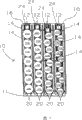
图1是正面透视图,示出了根据本发明的实施例的自动售货机托盘;Figure 1 is a front perspective view showing a vending machine tray according to an embodiment of the present invention;
图2是图1所示自动售货机托盘的局部放大图;Fig. 2 is a partially enlarged view of the tray of the automatic vending machine shown in Fig. 1;
图3是正面透视图,示出了根据本发明的实施例的部分分解的自动售货机托盘;Figure 3 is a front perspective view showing a partially exploded vending machine tray in accordance with an embodiment of the present invention;
图4是正面透视图,示出了根据本发明的实施例的部分分解的自动售货机托盘;Figure 4 is a front perspective view showing a partially exploded vending machine tray in accordance with an embodiment of the present invention;
图5是正面透视图图,示出了根据本发明的实施例的两个未连接的自动售货机托盘;Figure 5 is a front perspective view showing two unconnected vending machine trays in accordance with an embodiment of the present invention;
图6是正面透视图,示出了根据本发明的实施例的两个已连接的自动售货机托盘;Figure 6 is a front perspective view showing two connected vending machine trays in accordance with an embodiment of the present invention;
图7是俯视图,示出了根据本发明的实施例的其中装载有产品的两个已连接的自动售货机托盘;Figure 7 is a top view showing two connected vending machine trays loaded with product therein according to an embodiment of the present invention;
图8是后透视图,示出了根据本发明的实施例的部分装配的自动售货机托盘;Figure 8 is a rear perspective view showing a partially assembled vending machine tray in accordance with an embodiment of the present invention;
图9是升降器的局部视图,该升降器与本发明所述的托盘一起使用,该托盘具有缩回的产品分配驱动装置;Figure 9 is a partial view of an elevator for use with a tray according to the present invention having a retracted product dispensing drive;
图10是升降器的局部视图,该升降器与本发明所述的托盘一起使用,该托盘具有伸出的产品分配驱动装置;和Figure 10 is a partial view of an elevator for use with a tray according to the present invention having an extended product dispensing drive; and
图11是正面透视图,示出了部分装配的自动售货机托盘,该托盘带有缩回的及伸出的产品存在指示器Figure 11 is a front perspective view showing a partially assembled vending machine tray with retracted and extended product presence indicators
具体实施方式Detailed ways
尽管本发明可以有许多不同形式的实施例,但是,此处在附图中示出并将于此详细描述本发明的优选实施例,这是基于这样的理解:本次所公开内容被视为是本发明原理的例证,并不是要将本发明的广阔范围限定到所示实施例中。While the invention may be embodied in many different forms, preferred embodiments of the invention are shown in the drawings and will be described in detail herein, with the understanding that this disclosure is to be considered are illustrative of the principles of the invention and are not intended to limit the broad scope of the invention to the embodiments shown.
参照图1,本发明是一种自动售货机的托盘10。尽管并不排斥将本发明的应用到饮料之外的物品,但是该托盘最适用于自动出售的饮料,例如汽水、水、果汁等。托盘10具有前部11,并包括由直立壁14所限定的行12,该直立壁14连接到具有前部17的底座16上。如图2所示,在壁14的端部18连接有一对弹性臂20。两个弹性臂20从各壁14上伸出,使得一对来自相邻壁14的臂20相互合作,从而至少部分阻挡每个行12的端部。位于通道13内部的是螺纹轴22,该通道13形成在底座16的各行12内部,该螺纹轴22被以螺纹方式连接到产品止挡或驱动元件24中。Referring to FIG. 1 , the present invention is a
图3或图4示出了,各螺纹轴22具有齿轮26,该齿轮26位于底座16的前部17附近。每个齿轮26被带有配合齿轮30的可旋转驱动轴28驱动。驱动轴28还限定了光滑的外表面32。同样设置在底座16的前部17,并位于驱动轴28附近的是缠绕在可旋转弹簧轴36周围的线性卷簧34。弹簧34的端部连接到该驱动轴28,并且弹簧34的另一段连接到该弹簧轴36。驱动轴28和弹簧轴36被固定到底座16上,并分别位于驱动轴孔38内和弹簧轴销40上。随着顺时针旋转驱动轴28,弹簧34被缠绕在驱动轴28的光滑外表面32的周围,并且随着弹簧34展开,弹簧轴36逆时针旋转。但是,由于弹簧34被沿着与弹簧轴36相反的方向缠绕在驱动轴28的附近,因而弹簧34的自然偏置使弹簧34抵抗向驱动轴28上的缠绕。因此,弹簧34的自然偏置逆时针推动驱动轴28。FIG. 3 or FIG. 4 shows that each threaded
如上所述,产品驱动元件24被以螺纹方式连接到螺纹轴22上。由于驱动轴28被逆时针驱动,驱动轴28驱动螺纹轴22顺时针通过配合的齿轮26和30。该螺纹轴22被顺时针驱动的结果是,产品驱动元件24被驱动到行12的前部11。As mentioned above, the
参照图5,底座16的右侧42限定了互锁的指状件44,底座16的左侧45限定了互锁的指状件46。当底座16的左侧挨着另一个底座16的右侧放置时,所述指状件互锁,以致两个底座16可被锁定在一起,以形成一个较大的托盘10,如图6所示。Referring to FIG. 5 , the
在优选实施例中,托盘由两个行12构成。因此,通过将底座16锁定在一起,由奇数个行12构成的较大托盘10可用在不同大小的自动售货机中。但是,没有什么应该被解释成将本发明限定在任何特定数量的行中,在不背离本发明的范围的情况下,更多或更少的行都可用于托盘中,例如锁定在一起形成较大托盘的仅具有单个行的底座。In a preferred embodiment, the pallet consists of two
为了使用本发明所述的装置,底座16被互锁在一起,以形成具有适当宽度的适用于特定自动售货机的托盘10。还将多行托盘设置在自动售货机内部,托盘10的行12装有待出售的产品,如图7所示。产品100可以具有多种尺寸,与行12的宽度一样大的尺寸,或者比行12的一半宽度略大的尺寸。为了将产品保持在行的前部附近,产品驱动元件24邻接最后面的产品100,并且由弹簧34提供的力推动行12内部的产品100,并使其抵靠在位于托盘10前部11的弹性臂20上。以这种方式,产品100等待着被机器出售。To use the apparatus of the present invention, the
当到了出售产品100的时候,如图8所示,升降器102被移动到预期的用于出售的产品行12处。该升降器102包括用于保持所出售产品,并将其传送到客户拾取台(未示出)的杯状件。升降器102通过首先移动到产品的位于自动售货机内部的行12的预期位置上而确定了待出售产品的精确位置。但是,因为自动售货机箱可能由于放置在不平坦的地面上或者仅仅由于制造公差而扭曲,所以预期位置并不是包含待出售产品的行12的精确位置。为了找到该精确的位置,升降器102开始在预期位置的区域中搜寻,直到升降器102所携带的传感器103,例如霍耳效应传感器或簧片开关定位指示器105,例如磁铁,这种指示器105被相对于每个行12的位置加以定位。一旦升降器发现与行12相关的指示器,位于升降器12内部的机电装置(未示出)就将产品分配驱动装置从缩回位置(图9)延伸到伸出位置(图10)。产品分配驱动装置104具有与驱动轴28相配合的形状,并且与该驱动轴28配合来旋转该轴。由于驱动轴28被升降器102旋转,产品驱动元件24朝升降器102推动产品100,并经过弹性臂20。一旦产品100经过了该弹性臂20,它就进入升降器102,并且升降器102的产品分配驱动装置104停止旋转。该升降器102的产品分配驱动装置104随后被缩回,并且该升降器102拾取要分配给客户的产品100。When it is time to sell the
作为选择,传感器103可被设置在升降器上,该升降器针对产品驱动元件24检测指示器48的存在,如图11所示。当产品100位于行12内部时,指示器48被缩回,并不被传感器所检测到。以这种方式,自动售货机确定产品100保持在特定的行中。当产品100不再位于行12内部时,指示器48就伸出来,并被传感器所检测到,因此,在尝试出售该产品前,就检测到产品100是不存在的,并警告消费者作出另一个产品选择。Alternatively, the sensor 103 may be provided on a lifter that detects the presence of the
作为替换,并不是直接检测产品的存在或不存在,产品升降器102可尝试出售产品,如果在确定的时间段后,没有产品100进行分配,那么自动售货机将确定,在行中并没有产品存在。Alternatively, rather than directly detecting the presence or absence of a product, the
尽管已经对特定的实施例进行说明及描述,但是在不明显地背离本发明的精神的情况下,将会想出多种改进。While particular embodiments have been illustrated and described, various modifications will be envisioned without departing significantly from the spirit of the invention.
相关申请的交叉引用Cross References to Related Applications
本申请要求于2005年7月21日提交的第60/701,269号美国临时专利申请及于2005年6月2日提交的第60/686,729号美国临时专利申请的优先权。所述申请的内容被合并于此作为参考。This application claims priority to US Provisional Patent Application No. 60/701,269, filed July 21, 2005, and US Provisional Patent Application No. 60/686,729, filed June 2, 2005. The contents of said application are hereby incorporated by reference.
Claims (18)
Applications Claiming Priority (5)
| Application Number | Priority Date | Filing Date | Title |
|---|---|---|---|
| US68672905P | 2005-06-02 | 2005-06-02 | |
| US60/686,729 | 2005-06-02 | ||
| US70126905P | 2005-07-21 | 2005-07-21 | |
| US60/701,269 | 2005-07-21 | ||
| PCT/US2006/021408 WO2006130814A2 (en) | 2005-06-02 | 2006-06-02 | Dispenser tray for a vending machine |
Publications (2)
| Publication Number | Publication Date |
|---|---|
| CN101218610A CN101218610A (en) | 2008-07-09 |
| CN101218610B true CN101218610B (en) | 2010-11-10 |
Family
ID=37067406
Family Applications (1)
| Application Number | Title | Priority Date | Filing Date |
|---|---|---|---|
| CN2006800250477A Expired - Fee Related CN101218610B (en) | 2005-06-02 | 2006-06-02 | Dispensing trays for vending machines |
Country Status (7)
| Country | Link |
|---|---|
| US (1) | US7686185B2 (en) |
| EP (1) | EP1886283B1 (en) |
| CN (1) | CN101218610B (en) |
| AU (1) | AU2006252365A1 (en) |
| CA (1) | CA2609920A1 (en) |
| DE (1) | DE602006016784D1 (en) |
| WO (1) | WO2006130814A2 (en) |
Families Citing this family (51)
| Publication number | Priority date | Publication date | Assignee | Title |
|---|---|---|---|---|
| US6892941B2 (en) | 2000-06-08 | 2005-05-17 | Mendota Healthcare, Inc. | Automatic prescription drug dispenser |
| US9898712B2 (en) | 2004-02-03 | 2018-02-20 | Rtc Industries, Inc. | Continuous display shelf edge label device |
| US11375826B2 (en) | 2004-02-03 | 2022-07-05 | Rtc Industries, Inc. | Product securement and management system |
| US8938396B2 (en) | 2004-02-03 | 2015-01-20 | Rtc Industries, Inc. | System for inventory management |
| US8047385B2 (en) | 2004-02-03 | 2011-11-01 | Rtc Industries, Inc. | Product securement and management system |
| US9375100B2 (en) | 2004-02-03 | 2016-06-28 | Rtc Industries, Inc. | Product securement and management system |
| US9818148B2 (en) | 2013-03-05 | 2017-11-14 | Rtc Industries, Inc. | In-store item alert architecture |
| US9706857B2 (en) | 2004-02-03 | 2017-07-18 | Rtc Industries, Inc. | Product securement and management system |
| US9232864B2 (en) | 2005-09-12 | 2016-01-12 | RTC Industries, Incorporated | Product management display system with trackless pusher mechanism |
| US11259652B2 (en) | 2005-09-12 | 2022-03-01 | Rtc Industries, Inc. | Product management display system |
| US9060624B2 (en) | 2005-09-12 | 2015-06-23 | Rtc Industries, Inc. | Product management display system with rail mounting clip |
| US10952546B2 (en) | 2005-09-12 | 2021-03-23 | Rtc Industries, Inc. | Product management display system with trackless pusher mechanism |
| US11583109B2 (en) | 2005-09-12 | 2023-02-21 | Rtc Industries, Inc. | Product management display system with trackless pusher mechanism |
| US11344138B2 (en) | 2005-09-12 | 2022-05-31 | Rtc Industries, Inc. | Product management display system |
| US9259102B2 (en) | 2005-09-12 | 2016-02-16 | RTC Industries, Incorporated | Product management display system with trackless pusher mechanism |
| US8967394B2 (en) | 2005-09-12 | 2015-03-03 | Rtc Industries, Inc. | Product management display system with trackless pusher mechanism |
| US8978904B2 (en) | 2005-09-12 | 2015-03-17 | Rtc Industries, Inc. | Product management display system with trackless pusher mechanism |
| US9265358B2 (en) | 2005-09-12 | 2016-02-23 | RTC Industries, Incorporated | Product management display system |
| US9750354B2 (en) | 2005-09-12 | 2017-09-05 | Rtc Industries, Inc. | Product management display system |
| US8739984B2 (en) | 2005-09-12 | 2014-06-03 | Rtc Industries, Inc. | Product management display system with trackless pusher mechanism |
| US10285510B2 (en) | 2005-09-12 | 2019-05-14 | Rtc Industries, Inc. | Product management display system |
| US9486088B2 (en) | 2005-09-12 | 2016-11-08 | Rtc Industries, Inc. | Product management display system |
| US9265362B2 (en) | 2005-09-12 | 2016-02-23 | RTC Industries, Incorporated | Product management display system |
| US9138075B2 (en) | 2005-09-12 | 2015-09-22 | Rtc Industries, Inc. | Product management display system |
| US9173504B2 (en) | 2005-09-12 | 2015-11-03 | Rtc Industries, Inc. | Product management display system |
| ITPN20060076A1 (en) * | 2006-10-09 | 2008-04-10 | N & W Global Vending Spa | AUTOMATIC PRODUCT DISTRIBUTOR |
| GB2455115A (en) * | 2007-11-29 | 2009-06-03 | Lee Mulheron | Novelty game |
| US8038018B1 (en) * | 2008-03-25 | 2011-10-18 | Vendmore Systems, Llc | Vending machine product stabilizer |
| US7857148B2 (en) * | 2008-04-16 | 2010-12-28 | Roeske Pauline R | Jar dispenser |
| US8056740B2 (en) * | 2008-05-27 | 2011-11-15 | Target Brands, Inc. | Product display assembly and tester security apparatus |
| US8087522B2 (en) * | 2008-05-27 | 2012-01-03 | Target Brands, Inc. | Quick secure shelving |
| US20110017768A1 (en) * | 2009-07-20 | 2011-01-27 | Antonio Vardaro | Vertical small packet dispenser |
| NL2004342C2 (en) * | 2010-03-04 | 2011-09-06 | Automated Retail Concepts B V | Product dispensing machine and dispensing method. |
| US9640014B2 (en) | 2011-01-04 | 2017-05-02 | Fawn Engineering Corporation | Vending machine with elevator delivery of vended product to customer access |
| JP5822813B2 (en) * | 2012-10-15 | 2015-11-24 | ホンダ太陽株式会社 | Work sending device |
| US9870671B1 (en) | 2014-04-07 | 2018-01-16 | Fawn Engineering Corporation | Mechanical lift for delivery bins in vending machines |
| US11182738B2 (en) | 2014-11-12 | 2021-11-23 | Rtc Industries, Inc. | System for inventory management |
| US11109692B2 (en) | 2014-11-12 | 2021-09-07 | Rtc Industries, Inc. | Systems and methods for merchandizing electronic displays |
| US9955802B2 (en) | 2015-04-08 | 2018-05-01 | Fasteners For Retail, Inc. | Divider with selectively securable track assembly |
| US10178909B2 (en) | 2016-01-13 | 2019-01-15 | Rtc Industries, Inc. | Anti-splay device for merchandise display system |
| US9668590B1 (en) * | 2016-02-02 | 2017-06-06 | Bruegmann USA, Inc. | Retail product display unit having gravity operated front barrier for product loading |
| CN106327684A (en) * | 2016-08-30 | 2017-01-11 | 湖南金码智能设备制造有限公司 | Novel vending machine delivery mechanism |
| KR102305500B1 (en) | 2017-06-16 | 2021-09-24 | 알티씨 인더스트리즈, 인크. | Product Management Display System with Trackless Pusher Mechanism |
| CN109993898B (en) * | 2017-12-29 | 2024-09-06 | 山东新北洋信息技术股份有限公司 | Goods bucket and vending machine |
| CN109035570B (en) * | 2018-07-11 | 2024-04-05 | 王晓杰 | Vending equipment |
| CN110766860A (en) * | 2018-07-27 | 2020-02-07 | 威海新北洋数码科技有限公司 | Automatic vending machine |
| WO2020028878A1 (en) * | 2018-08-02 | 2020-02-06 | Swyft Inc. | Dispenser of shelved products |
| CN109830042B (en) * | 2019-01-30 | 2021-09-03 | 深圳市智莱科技股份有限公司 | Automatic sell goods way power supply system of equipment |
| IT201900003287A1 (en) * | 2019-03-07 | 2019-06-07 | Sandenvendo Europe S P A | Product conveyor device for vending machines |
| IT202100011759A1 (en) * | 2021-05-07 | 2022-11-07 | Everex S R L | VENDING MACHINE |
| CN218355373U (en) * | 2022-11-01 | 2023-01-24 | 东莞市永晟五金发条制品有限公司 | Commodity propeller |
Citations (7)
| Publication number | Priority date | Publication date | Assignee | Title |
|---|---|---|---|---|
| US2652154A (en) * | 1949-12-27 | 1953-09-15 | John F Mccarthy | Display rack |
| CN1164907A (en) * | 1995-08-25 | 1997-11-12 | 松下冷机株式会社 | Product storage device for vending machines |
| CN1301372A (en) * | 1998-03-20 | 2001-06-27 | 可口可乐公司 | Vending machine |
| EP1256912A1 (en) * | 2001-05-11 | 2002-11-13 | DPC International, Inc. | Dispensing machine for printed publication |
| US6604652B1 (en) * | 1998-10-10 | 2003-08-12 | Hans-Hermann Trautwein Sb-Technik Gmbh | Cigarette vending machine |
| CN2630957Y (en) * | 2003-07-22 | 2004-08-04 | 曹自林 | Automatic vending machine for liquid soft-packing goods |
| CN2630959Y (en) * | 2003-06-06 | 2004-08-04 | 青岛澳柯玛自动商用设备有限公司 | Discharging mechanism for automatic vending machine |
Family Cites Families (6)
| Publication number | Priority date | Publication date | Assignee | Title |
|---|---|---|---|---|
| US4858743A (en) | 1987-07-31 | 1989-08-22 | Datavend, Inc. | Vending machine and method for automatic vending and returning of merchandise, particularly video cassette tapes |
| US5121854A (en) | 1990-01-16 | 1992-06-16 | Hobart Corporation | Apparatus for storing and dispensing frozen comestibles |
| US6230932B1 (en) * | 1996-03-29 | 2001-05-15 | Dpc, International, Inc. | Dispensing machine for printed publication |
| US6755322B1 (en) * | 2000-02-22 | 2004-06-29 | Hettie J. Herzog | Automated shopping system and apparatus |
| EP1162582A3 (en) | 2000-06-05 | 2003-03-12 | Sanden Corporation | Automatic vending machine |
| JP2004318829A (en) | 2003-03-28 | 2004-11-11 | Sanden Corp | Vending machine |
-
2006
- 2006-06-02 DE DE602006016784T patent/DE602006016784D1/en active Active
- 2006-06-02 US US11/421,935 patent/US7686185B2/en not_active Expired - Fee Related
- 2006-06-02 CA CA002609920A patent/CA2609920A1/en not_active Abandoned
- 2006-06-02 WO PCT/US2006/021408 patent/WO2006130814A2/en not_active Ceased
- 2006-06-02 AU AU2006252365A patent/AU2006252365A1/en not_active Abandoned
- 2006-06-02 EP EP06760648A patent/EP1886283B1/en not_active Not-in-force
- 2006-06-02 CN CN2006800250477A patent/CN101218610B/en not_active Expired - Fee Related
Patent Citations (7)
| Publication number | Priority date | Publication date | Assignee | Title |
|---|---|---|---|---|
| US2652154A (en) * | 1949-12-27 | 1953-09-15 | John F Mccarthy | Display rack |
| CN1164907A (en) * | 1995-08-25 | 1997-11-12 | 松下冷机株式会社 | Product storage device for vending machines |
| CN1301372A (en) * | 1998-03-20 | 2001-06-27 | 可口可乐公司 | Vending machine |
| US6604652B1 (en) * | 1998-10-10 | 2003-08-12 | Hans-Hermann Trautwein Sb-Technik Gmbh | Cigarette vending machine |
| EP1256912A1 (en) * | 2001-05-11 | 2002-11-13 | DPC International, Inc. | Dispensing machine for printed publication |
| CN2630959Y (en) * | 2003-06-06 | 2004-08-04 | 青岛澳柯玛自动商用设备有限公司 | Discharging mechanism for automatic vending machine |
| CN2630957Y (en) * | 2003-07-22 | 2004-08-04 | 曹自林 | Automatic vending machine for liquid soft-packing goods |
Non-Patent Citations (1)
| Title |
|---|
| 同上. |
Also Published As
| Publication number | Publication date |
|---|---|
| AU2006252365A1 (en) | 2006-12-07 |
| US7686185B2 (en) | 2010-03-30 |
| CA2609920A1 (en) | 2006-12-07 |
| EP1886283B1 (en) | 2010-09-08 |
| EP1886283A2 (en) | 2008-02-13 |
| CN101218610A (en) | 2008-07-09 |
| WO2006130814A2 (en) | 2006-12-07 |
| US20060273104A1 (en) | 2006-12-07 |
| DE602006016784D1 (en) | 2010-10-21 |
| WO2006130814A3 (en) | 2007-01-25 |
Similar Documents
| Publication | Publication Date | Title |
|---|---|---|
| CN101218610B (en) | Dispensing trays for vending machines | |
| CN101258085B (en) | Automatic vending machine and its lifter receiving product method | |
| US3653540A (en) | Dispensing machine having multiple dual helix conveyors | |
| US6206237B1 (en) | Bottle dispenser | |
| US6415953B1 (en) | First-in first-out vending machine | |
| US6755322B1 (en) | Automated shopping system and apparatus | |
| US5009329A (en) | Dispensing apparatus | |
| US20050211721A1 (en) | Article storage magazine for an article handling device | |
| US20080164279A1 (en) | Article storage magazine for an article handling device | |
| WO2000060554A2 (en) | Vending machine which minimises agitation of goods | |
| US6540102B2 (en) | Apparatus and method for article dispensing | |
| US5472074A (en) | Coin operated dispensing machine | |
| US3533536A (en) | Serpentine column dispensing machine having associated pre-cool rack | |
| EP0899699B1 (en) | Beverage dispensing machine and method of operation thereof | |
| MX2007015168A (en) | Dispenser tray for a vending machine | |
| JP2871074B2 (en) | vending machine | |
| EP4280183A1 (en) | Vending machine for dispensing packaged products and method for dispensing a packaged product from a vending machine | |
| KR0135227B1 (en) | Article carrying out device for automatic vending machine | |
| US3137410A (en) | Coin-operated vending machines | |
| JP2622507B2 (en) | Product storage method and product storage device for vending machine | |
| JPH076257A (en) | Automatic vending machine and method for taking out commodity from the machine | |
| JP2001331865A (en) | Article ejecting device | |
| CZ2000475A3 (en) | Vending machine for dispensing packaged articles, particularly beverages | |
| CZ9801U1 (en) | Packed products - especially drinks - vending machine | |
| JP2019003447A (en) | Commodity storage column of automatic vending machine |
Legal Events
| Date | Code | Title | Description |
|---|---|---|---|
| C06 | Publication | ||
| PB01 | Publication | ||
| C10 | Entry into substantive examination | ||
| SE01 | Entry into force of request for substantive examination | ||
| C14 | Grant of patent or utility model | ||
| GR01 | Patent grant | ||
| C17 | Cessation of patent right | ||
| CF01 | Termination of patent right due to non-payment of annual fee |
Granted publication date: 20101110 Termination date: 20140602 |