CN101191509B - Fluid pressure cylinder - Google Patents
Fluid pressure cylinder Download PDFInfo
- Publication number
- CN101191509B CN101191509B CN2007101939820A CN200710193982A CN101191509B CN 101191509 B CN101191509 B CN 101191509B CN 2007101939820 A CN2007101939820 A CN 2007101939820A CN 200710193982 A CN200710193982 A CN 200710193982A CN 101191509 B CN101191509 B CN 101191509B
- Authority
- CN
- China
- Prior art keywords
- piston
- fluid pressure
- pressure cylinder
- cylinder
- rod
- Prior art date
- Legal status (The legal status is an assumption and is not a legal conclusion. Google has not performed a legal analysis and makes no representation as to the accuracy of the status listed.)
- Active
Links
Images


Classifications
-
- F—MECHANICAL ENGINEERING; LIGHTING; HEATING; WEAPONS; BLASTING
- F15—FLUID-PRESSURE ACTUATORS; HYDRAULICS OR PNEUMATICS IN GENERAL
- F15B—SYSTEMS ACTING BY MEANS OF FLUIDS IN GENERAL; FLUID-PRESSURE ACTUATORS, e.g. SERVOMOTORS; DETAILS OF FLUID-PRESSURE SYSTEMS, NOT OTHERWISE PROVIDED FOR
- F15B15/00—Fluid-actuated devices for displacing a member from one position to another; Gearing associated therewith
- F15B15/20—Other details, e.g. assembly with regulating devices
- F15B15/22—Other details, e.g. assembly with regulating devices for accelerating or decelerating the stroke
-
- F—MECHANICAL ENGINEERING; LIGHTING; HEATING; WEAPONS; BLASTING
- F15—FLUID-PRESSURE ACTUATORS; HYDRAULICS OR PNEUMATICS IN GENERAL
- F15B—SYSTEMS ACTING BY MEANS OF FLUIDS IN GENERAL; FLUID-PRESSURE ACTUATORS, e.g. SERVOMOTORS; DETAILS OF FLUID-PRESSURE SYSTEMS, NOT OTHERWISE PROVIDED FOR
- F15B15/00—Fluid-actuated devices for displacing a member from one position to another; Gearing associated therewith
- F15B15/08—Characterised by the construction of the motor unit
- F15B15/14—Characterised by the construction of the motor unit of the straight-cylinder type
- F15B15/1423—Component parts; Constructional details
- F15B15/1447—Pistons; Piston to piston rod assemblies
-
- F—MECHANICAL ENGINEERING; LIGHTING; HEATING; WEAPONS; BLASTING
- F15—FLUID-PRESSURE ACTUATORS; HYDRAULICS OR PNEUMATICS IN GENERAL
- F15B—SYSTEMS ACTING BY MEANS OF FLUIDS IN GENERAL; FLUID-PRESSURE ACTUATORS, e.g. SERVOMOTORS; DETAILS OF FLUID-PRESSURE SYSTEMS, NOT OTHERWISE PROVIDED FOR
- F15B15/00—Fluid-actuated devices for displacing a member from one position to another; Gearing associated therewith
- F15B15/08—Characterised by the construction of the motor unit
- F15B15/14—Characterised by the construction of the motor unit of the straight-cylinder type
-
- F—MECHANICAL ENGINEERING; LIGHTING; HEATING; WEAPONS; BLASTING
- F15—FLUID-PRESSURE ACTUATORS; HYDRAULICS OR PNEUMATICS IN GENERAL
- F15B—SYSTEMS ACTING BY MEANS OF FLUIDS IN GENERAL; FLUID-PRESSURE ACTUATORS, e.g. SERVOMOTORS; DETAILS OF FLUID-PRESSURE SYSTEMS, NOT OTHERWISE PROVIDED FOR
- F15B15/00—Fluid-actuated devices for displacing a member from one position to another; Gearing associated therewith
- F15B15/20—Other details, e.g. assembly with regulating devices
- F15B15/22—Other details, e.g. assembly with regulating devices for accelerating or decelerating the stroke
- F15B15/222—Other details, e.g. assembly with regulating devices for accelerating or decelerating the stroke having a piston with a piston extension or piston recess which throttles the main fluid outlet as the piston approaches its end position
Landscapes
- Engineering & Computer Science (AREA)
- Physics & Mathematics (AREA)
- Fluid Mechanics (AREA)
- Mechanical Engineering (AREA)
- General Engineering & Computer Science (AREA)
- Actuator (AREA)
- Pistons, Piston Rings, And Cylinders (AREA)
Abstract
第一和第二垫圈(62、64)分别通过配合槽(54a、54b)布置在构成流体压力缸(10)部件的活塞(18)的两端面(18a、18b)上。第一和第二垫圈(62、64)以基本中空的圆柱形状经压力加工由金属材料形成,其中垫圈(62、64)实现了缓冲作用,由于垫圈(62、64)与活塞(18)一同沿轴向移动且接收并容纳在气缸盖罩(14)的凹槽(24)和杆盖(16)的杆孔(34)内,活塞(18)的移动速度得以降低。
First and second gaskets (62, 64) are respectively arranged on both end surfaces (18a, 18b) of a piston (18) constituting a part of a fluid pressure cylinder (10) through fitting grooves (54a, 54b). The first and second gaskets (62, 64) are formed from metal material by press working in a substantially hollow cylindrical shape, wherein the gaskets (62, 64) achieve a cushioning effect, since the gaskets (62, 64) together with the piston (18) Moving in the axial direction and received and housed in the groove (24) of the cylinder head cover (14) and the rod hole (34) of the rod cover (16), the moving speed of the piston (18) is reduced.
Description
技术领域technical field
本发明涉及一种流体压力缸,其内的活塞在加压流体的供给情况下沿着轴向移动,尤其涉及一种具有能减缓并吸收在活塞位移终端位置上产生的冲击的缓冲机构的流体压力缸。The present invention relates to a fluid pressure cylinder in which the piston moves axially under the supply of pressurized fluid, and more particularly to a fluid with a buffer mechanism capable of slowing down and absorbing shocks generated at the end positions of piston displacement pressure cylinder.
背景技术Background technique
迄今为止,例如已经将其内具有在加压流体的供给情况下移动的活塞的流体压力缸用作传送各种工件等的传送装置。在这样的流体压力缸中,已知提供了一种缓冲机构来减缓并吸收在活塞位移终端位置上产生的冲击。Hitherto, for example, a fluid pressure cylinder having a piston therein that moves under supply of pressurized fluid has been used as a transfer device that transfers various workpieces and the like. In such fluid pressure cylinders, it is known to provide a damper mechanism to dampen and absorb shocks generated at the end positions of piston displacement.
例如在日本未审公开专利文献No.61-124706中披露的,具有此类缓冲机构的流体压力缸包括一个安置在缸内腔内的可移动活塞,其中缸内腔的一端由气缸盖罩封闭。沿轴向延伸的小活塞分别形成在活塞的两端面上,其中,小活塞在活塞的位移作用下插入气缸盖罩的小缸体中。因此,空气封闭在小缸体内,受到压缩而由此产生缓冲效应。For example, as disclosed in Japanese Unexamined Laid-Open Patent Document No. 61-124706, a fluid pressure cylinder with such a buffer mechanism includes a movable piston seated in a cylinder cavity, wherein one end of the cylinder cavity is closed by a cylinder head cover . Small pistons extending in the axial direction are respectively formed on both end surfaces of the pistons, wherein the small pistons are inserted into the small cylinder body of the cylinder head cover under the action of displacement of the pistons. Thus, the air is enclosed in the small cylinder and compressed thereby creating a cushioning effect.
不过,在根据日本未审公开专利文献No.61-124706的传统技术中,因为构成缓冲机构的小活塞是以实心非中空的轴形状形成的,其与活塞的一端面一体连接,与未设置此种缓冲机构的流体压力缸相比,流体压力缸的重量增大,而因为存在小活塞,制造成本也连带着增加。However, in the conventional technology according to Japanese Unexamined Patent Publication No. 61-124706, since the small piston constituting the buffer mechanism is formed in a solid non-hollow shaft shape, it is integrally connected with one end surface of the piston, and is not provided with Compared with the fluid pressure cylinder of this kind of buffer mechanism, the weight of the fluid pressure cylinder is increased, and because of the small piston, the manufacturing cost is also increased.
发明内容Contents of the invention
本发明的主要目的在于,提供一种流体压力缸,其能降低生产成本,同时使得流体压力缸的重量较轻。The main object of the present invention is to provide a fluid pressure cylinder, which can reduce the production cost, and at the same time make the weight of the fluid pressure cylinder light.
自下面结合通过例证性实例示出本发明一优选实施例的附图作出的说明,本发明的上述和其它目的、特征以及优点将显而易见。The above and other objects, features and advantages of the invention will become apparent from the following description taken in conjunction with the accompanying drawings showing a preferred embodiment of the invention by way of illustrative example.
附图说明Description of drawings
图1是根据本发明一实施例的流体压力缸的总垂直横截面图;1 is a general vertical cross-sectional view of a fluid pressure cylinder according to an embodiment of the present invention;
图2是图1流体压力缸的气缸盖罩附近的放大横截面图;Fig. 2 is an enlarged cross-sectional view near the cylinder head cover of the fluid pressure cylinder of Fig. 1;
图3是局部分解透视图,示出了图1流体压力缸中的活塞、第一和第二垫圈、垫片以及螺母与活塞杆分开的状态;3 is a partially exploded perspective view showing a state in which the piston, first and second washers, washers and nuts in the fluid pressure cylinder of FIG. 1 are separated from the piston rod;
图4是第一和第二垫圈的局部剖开透视图;Figure 4 is a partially cutaway perspective view of first and second gaskets;
图5是示出自不同方向观察的图4内容物的局部剖开透视图;Figure 5 is a partially cut-away perspective view showing the contents of Figure 4 viewed from different directions;
图6是总垂直横截面图,示出了图1流体压力缸中的活塞移动到杆盖那侧的状态。Fig. 6 is a general vertical cross-sectional view showing a state in which the piston in the fluid pressure cylinder of Fig. 1 is moved to the side of the rod cover.
具体实施方式Detailed ways
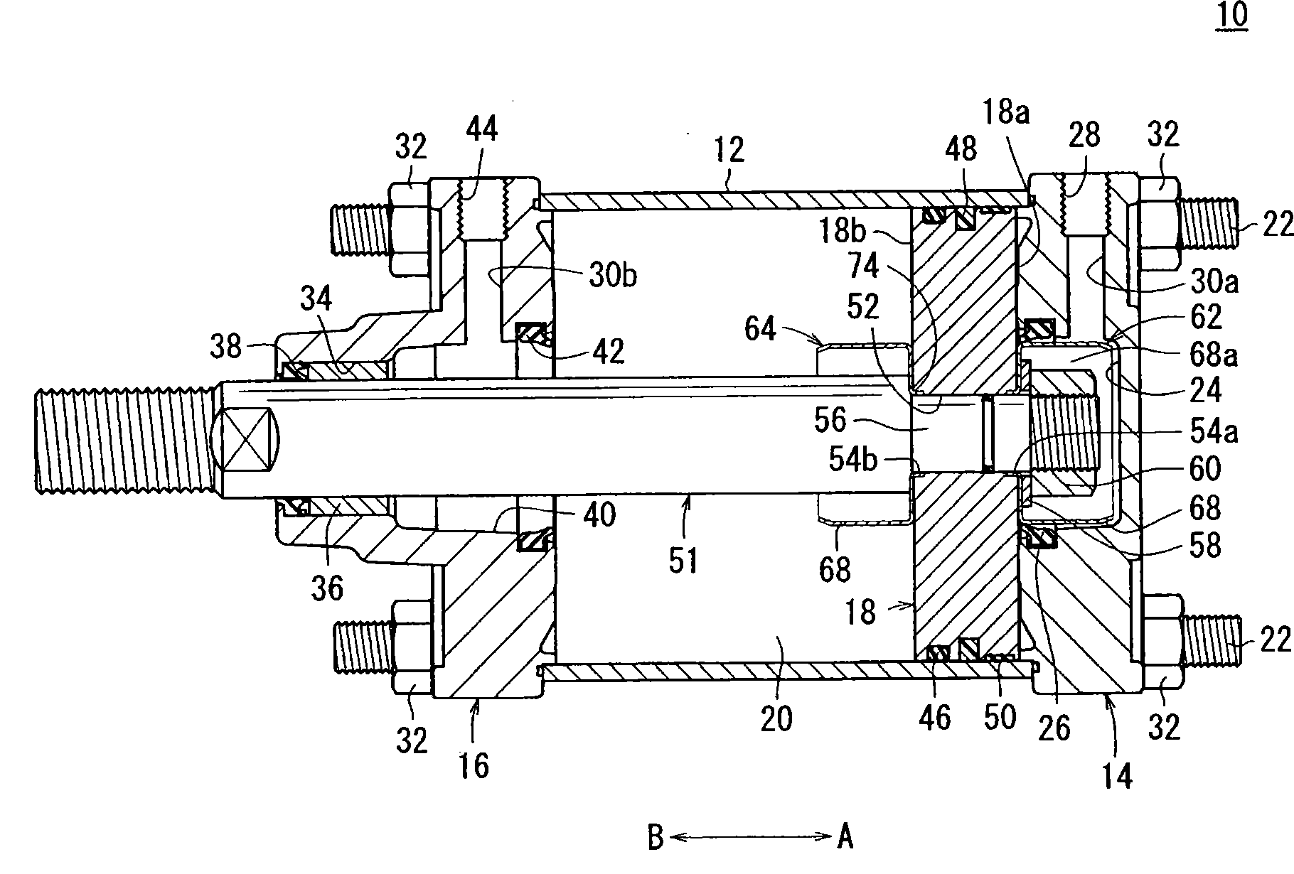
在图1中,参照标号10表示根据本发明一实施例的流体压力缸。In FIG. 1,
如图1至3所示,流体压力缸10包括圆柱形的缸筒(缸体)12、装在缸筒12一端上的气缸盖罩(覆盖元件)14、装在缸筒12另一端上的杆盖(覆盖元件)16、以及可移动地安置在缸筒12内的活塞18。As shown in Figures 1 to 3, the
缸筒12由直径基本恒定的圆柱体形成,其内形成有一个缸内腔20,活塞18容纳在该缸内腔20内。
气缸盖罩14例如由比如铝合金等的金属材料形成,横截面形状基本呈矩形,具有若干通孔(未示出),它们沿轴向在其四个角贯穿气缸盖罩14,且从中插入有连杆22。The
此外,凹槽(容纳孔)24以预定深度面朝缸筒12那侧形成在气缸盖罩14的中心。第一密封圈26安装在沿着凹槽24的内圆周面形成的环形槽中。凹槽24的横截面形成为直径基本恒定的圆形形状,并且,当气缸盖罩14安装到缸筒12的一端上时与缸内腔20相通。Further, a groove (accommodating hole) 24 is formed at the center of the
另外,供给并排放加压流体的第一流体口28安置在气缸盖罩14的侧面上,其中第一流体口28通过连通通道30a与凹槽24相通。具体地说,自第一流体口28供给的加压流体通过连通通道30a引入凹槽24中。In addition, a
杆盖16例如由比如铝合金等的金属材料形成,横截面形状基本呈矩形,具有若干通孔(未示出),它们沿轴向在其四个角贯穿气缸盖罩14,且从中插入有连杆22。当气缸盖罩14和杆盖16安装到缸筒12的两端部上时,通孔分别沿着同一直线同线布置,螺母32旋到连杆22的两端上并与之接合,连杆22各自通过彼此面对的通孔插入。由此,气缸盖罩14和杆盖16与缸筒12连接。除非另有说明,因为气缸盖罩14和杆盖16在张力之下位于彼此相互接近的方向上,所以缸筒12被夹持并保持在气缸盖罩14与杆盖16之间。The
此外,杆盖16的中央部在远离缸筒12的方向上鼓出和突伸,其内形成有杆孔34,它沿轴向贯穿中央部。衬套36和杆密封垫38沿着杆孔34的内圆周面安装。杆孔34包括扩展直径部(容纳孔)40,其朝着缸筒12的侧面(沿箭头A的方向)在直径上逐渐扩展,其中第二密封圈42通过环形槽安装在扩展直径部40的内圆周面上。扩展直径部40的内径大致等于凹槽24的内径。当杆盖16安装到缸筒12的另一端上时,杆孔34与缸内腔20相通。In addition, the central portion of the
另外,供给并排放加压流体的第二流体口44安置在杆盖16的侧面上,其中第二流体口44通过连通通道30b与杆孔34相通。具体地说,自第二流体口44供给的加压流体通过连通通道30b引入杆孔34和缸内腔20中。In addition, a
活塞18的横截面形状基本呈圆形,与缸筒12的横截面形状相对应。活塞密封垫46、磁铁48以及耐磨环50通过若干环形槽安装在活塞18的外圆周面上。The cross-sectional shape of the
此外,沿轴向(箭头A和B的方向)贯穿的活塞孔52形成在活塞18的中心,其中活塞杆51的一端通过活塞孔52插入。活塞孔52在其内分别包括位于活塞18两端面侧上的配合槽54a、54b。配合槽54a、54b相对于活塞孔52在直径上只略微扩展,且形成为面朝缸内腔20。Further, a
活塞杆51包括连接段56,其一端直径减小且与活塞18连接,其中活塞18通过活塞孔52插到连接段56上。另外,活塞杆51的另一端通过杆孔34插入并由衬套36可移动地支承。顺着连接段56上的外圆周面刻有螺纹,于是在通过活塞孔52插入连接段56之后,将垫片58插在连接段56的上面且使连接螺母60与连接段56螺纹啮合。因此,活塞18就与活塞杆51的一端连接。The
另外,第一和第二垫圈(圈体)62、64分别通过配合槽54a、54b安装在活塞18的两端面上。第一和第二垫圈62、64形状基本相同,其中,第一垫圈62安置在气缸盖罩14侧面上活塞18的一端面18a上(箭头A的方向),而第二垫圈64安置在杆盖16侧面上活塞18的另一端面18b上(箭头B的方向)。In addition, first and second washers (ring bodies) 62, 64 are mounted on both end faces of the
如图1至3所示,第一和第二垫圈62、64都例如由诸如不锈钢的金属材料形成,均经压力加工形成圆柱形状。As shown in FIGS. 1 to 3, both the first and
具体而言,第一和第二垫圈62、64厚度基本恒定地由薄板材形成。装配到活塞18的配合槽54a、54b中的配件66形成在第一和第二垫圈62、64两者的端部上,而在其另一端,形成有圆柱部68,它们相对于配件66沿径向向外的方向在直径上扩展。将配件66和圆柱部68连接起来的连接部70形成在配件66与圆柱部68之间,与第一和第二垫圈62、64两者的轴线基本垂直。In particular, the first and
配件66相对于连接部70沿着轴向突伸出指定高度,其中,配件66的内部限定了一个让活塞杆51从中插入的孔72。具体地说,配件66通过孔72与圆柱部68的内部相通。The
圆柱部68的一端形成有沿远离配件66的方向直径渐减的锥形形状。更具体地说,当第一和第二垫圈62、64分别插入凹槽24和扩展直径部40中时,由于垫圈62、64自圆柱部68的锥形端接近并进入到凹槽24和扩展直径部40中,其运动就会平稳地实现,与此同时,活塞18的移动速度也平稳地减速。One end of the
第一垫圈62通过配件66装配接合到形成在活塞18的一个端面18a上的配合槽54a中而与活塞18连接,于是活塞杆51的连接段56就通过孔72插入。此外,在活塞杆51已经插入垫片58中之后,第一垫圈62的连接部70通过连接螺母60的螺纹啮合夹持在垫片58与活塞18之间。因此,在垫片58和连接螺母60容纳在形成于圆柱部68内的空间68a中的状态下,第一垫圈62与活塞18的一个端面18a连接。因此,垫片58和连接螺母60容纳在第一垫圈62内,由此限定了垫片58和连接螺母60自活塞18的一个端面18a突伸的量。The
另一方面,第二垫圈64通过配件66装配接合到形成在活塞18的另一个端面18b上的配合槽54b中而与活塞18连接。通过经由孔72插入的活塞杆51的阶梯部74与连接部70邻靠,第二垫圈64夹插在阶梯部74与活塞18之间。此外,通过连接螺母60与活塞杆51的螺纹啮合,第二垫圈64在活塞杆51经由圆柱部68插入的状态下与活塞18的另一端面18b连接。On the other hand, the
除非另有说明,否则第一垫圈62被布置成其圆柱部68朝向凹槽24的侧面(箭头A的方向)敞开,而第二垫圈64被布置成其圆柱部68朝向杆孔34的侧面(箭头B的方向)敞开。Unless otherwise specified, the
此外,圆柱部68的外径被设定成略小于凹槽24的内径和杆孔34扩展直径部40的内径,于是当圆柱部68插入凹槽24和杆孔34中时,第一和第二密封圈26、42与圆柱部68的外圆周面滑动接触。In addition, the outer diameter of the
上述第一和第二垫圈62、64并不局限于分别安置在活塞18的两端面18a、18b上。将垫圈仅安置在一个端面上,也是可接受的。The above-mentioned first and
根据本发明的流体压力缸10的基本结构如上所述。接下来,将对流体压力缸10的操作和效果作出解释。解释的前提条件是,活塞18朝向气缸盖罩14移动(箭头A的方向),如图1所示,并且,将第一垫圈62容纳在凹槽24内的状态视作初始位置。The basic structure of the
首先,将加压流体自未示出的加压流体供给源引入第一流体口28中。在此情况下,第二流体口44处于通过未示出的方向控制阀的切换操作向大气敞开的状态下。First, pressurized fluid is introduced into the first
因此,加压流体通过连通通道30a自第一流体口28供给到凹槽24中。活塞18随后依靠自凹槽24引入缸内腔20中的加压流体压向杆盖16(箭头B的方向)。此外,活塞杆51因活塞18移动而移动,其中,安装在活塞杆51端部上的第一垫圈62脱离并远离凹槽24,同时与第一密封圈26滑动接触。Accordingly, pressurized fluid is supplied from the first
接着,活塞18一移动,第二垫圈64便插入杆孔34的扩展直径部40中,由此加压流体的流量被限制和压缩在缸内腔20内。因此,产生活塞18移动时的移动阻力,随着活塞18向其位移终端位置的靠近,活塞18的移动速度逐渐减小。也就是说,执行了缓冲效应,这能降低活塞18的移动速度。Next, upon movement of the
最后,活塞18持续着逐渐朝杆盖16侧面移动的状态,如此一来,通过第二垫圈64完全容纳在杆孔34内,活塞18到达横靠杆盖16的其位移终端位置(箭头B的方向,见图6)。Finally, the
另一方面,在活塞18反向移动(箭头A的方向)的情况下,加压流体供给到第二流体口44,且第一流体口28处于通过未示出的方向控制阀的切换操作通向大气的状态下。此外,加压流体通过通道30b自第二流体口44供给到杆孔34中,活塞18随后依靠自杆孔34引入缸内腔20中的加压流体压向气缸盖罩14(箭头A的方向)。On the other hand, in the case where the
此外,活塞杆51因活塞18移动而移动,其中,安装在活塞杆51端部上的第二垫圈64脱离并远离扩展直径部40,同时与第二密封圈42滑动接触。In addition, the
接着,第一垫圈62通过活塞18的移动而插入凹槽24中,由此来自缸内腔20并且经由凹槽24的加压流体的流量被限制和压缩在缸内腔20内。因此,产生活塞18移动时的移动阻力,且活塞18的移动速度逐渐减小。之后,活塞18回复到其初始位置(见图1),活塞18在该位置上顶着气缸盖罩14的侧面移动(箭头A的方向)。Next, the
正如上面讨论的那样,在本实施例中,第一和第二垫圈62、64安置在活塞18的两端面18a、18b上,其中,第一和第二垫圈62、64以中空圆柱形状由薄板金属材料压力加工而成。因此,与具有由形成有实心轴形状的小活塞构成的缓冲机构的传统流体压力缸相比,可进一步减轻流体压力缸10的重量。As discussed above, in this embodiment, the first and
另外,通过由铝合金形成气缸盖罩14和杆盖16,连同第一和第二垫圈62、64在内,也进一步减轻了流体压力缸10的重量。In addition, by forming the
再有,因为无需在第一和第二垫圈62、64上进行额外的加工(这缘于第一和第二垫圈62、64仅由薄板金属材料压力加工而成的事实),制造成本得以降低。除非另有说明,中空圆柱形的第一和第二垫圈62、64都可低成本地制造,且第一和第二垫圈62、64的配件66和圆柱部68都能很容易地成形。Also, because no additional machining is required on the first and
此外,通过在第一和第二垫圈62、64的端部上设置配件66,其朝活塞18的侧面突伸且装配到活塞18的配合槽54a、54b中,第一和第二垫圈62、64就可容易地经由配件66与活塞18连接,由此第一和第二垫圈62、64可与活塞18合为一体地移动。Furthermore, by providing
本发明的流体压力缸10不局限于上述实施例,而是可采用其各种其它不脱离本发明基本特征和要旨的结构和构造。The
Claims (6)
Applications Claiming Priority (3)
| Application Number | Priority Date | Filing Date | Title |
|---|---|---|---|
| JP2006-321519 | 2006-11-29 | ||
| JP2006321519 | 2006-11-29 | ||
| JP2006321519A JP2008133920A (en) | 2006-11-29 | 2006-11-29 | Fluid pressure cylinder |
Publications (2)
| Publication Number | Publication Date |
|---|---|
| CN101191509A CN101191509A (en) | 2008-06-04 |
| CN101191509B true CN101191509B (en) | 2010-12-01 |
Family
ID=39339104
Family Applications (1)
| Application Number | Title | Priority Date | Filing Date |
|---|---|---|---|
| CN2007101939820A Active CN101191509B (en) | 2006-11-29 | 2007-11-29 | Fluid pressure cylinder |
Country Status (6)
| Country | Link |
|---|---|
| US (1) | US7798052B2 (en) |
| JP (1) | JP2008133920A (en) |
| KR (1) | KR100956590B1 (en) |
| CN (1) | CN101191509B (en) |
| DE (1) | DE102007054224A1 (en) |
| TW (1) | TWI351478B (en) |
Families Citing this family (29)
| Publication number | Priority date | Publication date | Assignee | Title |
|---|---|---|---|---|
| JP4529093B2 (en) * | 2007-12-19 | 2010-08-25 | Smc株式会社 | Piston position detection device for fluid pressure cylinder |
| JP5323566B2 (en) * | 2009-04-02 | 2013-10-23 | カヤバ工業株式会社 | Hydraulic cylinder |
| US20110011257A1 (en) * | 2009-07-16 | 2011-01-20 | Parker Hannifin Corporation | Electro-hydraulic actuator having end cap with split bushing |
| JP5308961B2 (en) * | 2009-08-27 | 2013-10-09 | カヤバ工業株式会社 | Fluid pressure cylinder |
| KR100941373B1 (en) * | 2009-09-11 | 2010-02-05 | 티엠디이엔지(주) | Hydraulic actuator and maintenance method for use in generator equipment |
| CN101982301A (en) * | 2010-08-30 | 2011-03-02 | 兰州瑞德实业集团有限公司 | Compact sensitive cylinder |
| CN102269273B (en) * | 2011-05-11 | 2015-10-14 | 无锡市华通气动制造有限公司 | Air cylinder leakproof structure and sealing material thereof |
| CN102182721A (en) * | 2011-05-23 | 2011-09-14 | 何少敦 | Piston type speed controller |
| JP5854387B2 (en) * | 2013-05-16 | 2016-02-09 | Smc株式会社 | Fluid pressure cylinder |
| JP3191509U (en) | 2014-04-14 | 2014-06-26 | Smc株式会社 | Fluid pressure cylinder |
| JP6159938B2 (en) | 2014-04-14 | 2017-07-12 | Smc株式会社 | Fluid pressure cylinder |
| JP6519864B2 (en) * | 2015-06-11 | 2019-05-29 | Smc株式会社 | Fluid pressure cylinder |
| JP6403072B2 (en) | 2015-06-11 | 2018-10-10 | Smc株式会社 | Fluid pressure cylinder |
| JP6292483B2 (en) | 2015-06-11 | 2018-03-14 | Smc株式会社 | Fluid pressure cylinder |
| JP6403073B2 (en) * | 2015-06-11 | 2018-10-10 | Smc株式会社 | Fluid pressure cylinder |
| JP6519865B2 (en) | 2015-06-11 | 2019-05-29 | Smc株式会社 | Fluid pressure cylinder |
| JP6403071B2 (en) | 2015-06-11 | 2018-10-10 | Smc株式会社 | Fluid pressure cylinder |
| JP6647551B2 (en) * | 2015-10-14 | 2020-02-14 | Smc株式会社 | Fluid pressure device and manufacturing method thereof |
| JP6590217B2 (en) * | 2016-06-20 | 2019-10-16 | Smc株式会社 | Cylinder device |
| JP6606807B2 (en) * | 2017-03-08 | 2019-11-20 | Smc株式会社 | Shaft coupling structure and fluid pressure device |
| JP6673555B2 (en) | 2017-05-08 | 2020-03-25 | Smc株式会社 | Fluid pressure cylinder |
| JP6808183B2 (en) | 2017-09-07 | 2021-01-06 | Smc株式会社 | Piston unit and fluid pressure cylinder |
| JP6808182B2 (en) | 2017-09-07 | 2021-01-06 | Smc株式会社 | Fluid pressure cylinder |
| JP6718584B2 (en) | 2018-01-26 | 2020-07-08 | Smc株式会社 | Fluid pressure cylinder |
| JP6997977B2 (en) * | 2018-02-28 | 2022-01-18 | Smc株式会社 | Seal structure in fluid pressure cylinder and its fluid pressure cylinder |
| JP6751916B2 (en) * | 2018-03-23 | 2020-09-09 | Smc株式会社 | Fluid pressure cylinder |
| CN113531196A (en) * | 2020-04-20 | 2021-10-22 | 厦门仁工环保科技有限公司 | A high-pressure multi-way valve with integrated fluid control and method of using the same |
| CA3212573A1 (en) * | 2021-03-23 | 2022-09-29 | Prasanna V. Kulkarni | Hydraulic cylinder snubbing retention arrangement |
| US11319972B1 (en) * | 2021-05-11 | 2022-05-03 | Caterpillar Inc. | Hydraulic cylinder snubbing retention arrangement |
Citations (2)
| Publication number | Priority date | Publication date | Assignee | Title |
|---|---|---|---|---|
| CN85107198A (en) * | 1985-09-28 | 1987-03-11 | 上海市液压气动技术研究所 | The single rod cylinder of the double-action of the removable installation of standard type |
| CN2168977Y (en) * | 1993-08-03 | 1994-06-15 | 包头市青山区节能技术研究所 | Permanent magnet energy saving cylinder |
Family Cites Families (24)
| Publication number | Priority date | Publication date | Assignee | Title |
|---|---|---|---|---|
| US3296942A (en) | 1965-03-08 | 1967-01-10 | Int Harvester Co | Deceleration control for piston of conventional hydraulic cylinder |
| US3440930A (en) * | 1966-07-18 | 1969-04-29 | Westinghouse Air Brake Co | Cushion seal device for power cylinders |
| DE1601749A1 (en) | 1968-01-15 | 1970-05-21 | Hermann Post | Hydraulic or pneumatic working cylinder |
| SE347046B (en) | 1969-11-07 | 1972-07-24 | Monsun Tison Ab | |
| US4088061A (en) * | 1973-11-07 | 1978-05-09 | Kurt Stoll | Piston/cylinder assemblies |
| DE2654347A1 (en) | 1976-12-01 | 1978-06-08 | Bayer Ag | POLYPARABANIC ACID DERIVATIVES |
| JPS579525Y2 (en) * | 1977-09-17 | 1982-02-24 | ||
| JPS5451288A (en) | 1977-09-30 | 1979-04-21 | Nec Home Electronics Ltd | Method of producing discharge lamp |
| JPS5889603A (en) | 1981-11-24 | 1983-05-28 | Denki Kagaku Kogyo Kk | Manufacture of copolymer |
| JPS6030529A (en) | 1983-07-28 | 1985-02-16 | Aida Eng Ltd | Piercing method of stepped cylinder |
| JPS6073107A (en) | 1983-09-28 | 1985-04-25 | Taiyo Tekko Kk | Cushion device of fluid pressure cylinder |
| JPS61124706A (en) | 1984-11-16 | 1986-06-12 | Taiyo Tekko Kk | Air cylinder with cushion device |
| JPH0816003B2 (en) | 1986-12-27 | 1996-02-21 | 株式会社アドバンス | Method for producing inorganic oxide |
| JPH0699151B2 (en) | 1989-08-23 | 1994-12-07 | 工業技術院長 | Lipophilic modified basic calcium carbonate and method for producing the same |
| JP2731667B2 (en) | 1992-04-17 | 1998-03-25 | 株式会社クボタ | Hydraulic cylinder |
| JPH0734239A (en) | 1993-07-22 | 1995-02-03 | Matsushita Electric Ind Co Ltd | Sputtering equipment |
| JPH07100550A (en) | 1993-10-04 | 1995-04-18 | Canon Precision Inc | Embossing with side wall holes |
| JPH09295071A (en) | 1996-04-26 | 1997-11-18 | Toshiba Electron Eng Corp | Press processing method and apparatus |
| JPH10299718A (en) | 1997-04-24 | 1998-11-10 | Ckd Corp | Fluid pressure cylinder with shock absorber, method of manufacturing piston having shock absorber, method of manufacturing cylinder cover having shock absorber |
| JP2000337314A (en) | 1999-05-27 | 2000-12-05 | Hitachi Constr Mach Co Ltd | Cushion device of hydraulic cylinder |
| IT1319005B1 (en) * | 2000-10-16 | 2003-09-19 | Luciano Migliori | COMPACT PNEUMATIC CYLINDER WITH CUSHIONING DEVICE |
| JP4010116B2 (en) | 2001-03-07 | 2007-11-21 | トヨタ自動車株式会社 | Press drawing method for perforated bottomed cups |
| DE20219451U1 (en) * | 2002-12-13 | 2003-04-24 | TRW Fahrwerksysteme GmbH & Co KG, 40547 Düsseldorf | hydraulic cylinders |
| DE102005032853B3 (en) * | 2005-07-14 | 2007-02-08 | Norgren Gmbh | Working cylinder with cushioning |
-
2006
- 2006-11-29 JP JP2006321519A patent/JP2008133920A/en active Pending
-
2007
- 2007-10-31 US US11/932,332 patent/US7798052B2/en active Active
- 2007-11-14 DE DE102007054224A patent/DE102007054224A1/en not_active Withdrawn
- 2007-11-14 TW TW096142974A patent/TWI351478B/en not_active IP Right Cessation
- 2007-11-29 KR KR1020070122602A patent/KR100956590B1/en active Active
- 2007-11-29 CN CN2007101939820A patent/CN101191509B/en active Active
Patent Citations (2)
| Publication number | Priority date | Publication date | Assignee | Title |
|---|---|---|---|---|
| CN85107198A (en) * | 1985-09-28 | 1987-03-11 | 上海市液压气动技术研究所 | The single rod cylinder of the double-action of the removable installation of standard type |
| CN2168977Y (en) * | 1993-08-03 | 1994-06-15 | 包头市青山区节能技术研究所 | Permanent magnet energy saving cylinder |
Non-Patent Citations (3)
| Title |
|---|
| JP昭53-71198 1978.06.14 |
| JP昭58-89603U 1983.06.17 |
| JP特开平9-295071A 1997.11.18 |
Also Published As
| Publication number | Publication date |
|---|---|
| CN101191509A (en) | 2008-06-04 |
| KR20080048970A (en) | 2008-06-03 |
| US20080173169A1 (en) | 2008-07-24 |
| DE102007054224A1 (en) | 2008-06-05 |
| US7798052B2 (en) | 2010-09-21 |
| TW200839124A (en) | 2008-10-01 |
| JP2008133920A (en) | 2008-06-12 |
| KR100956590B1 (en) | 2010-05-11 |
| TWI351478B (en) | 2011-11-01 |
Similar Documents
| Publication | Publication Date | Title |
|---|---|---|
| CN101191509B (en) | Fluid pressure cylinder | |
| CN103867522B (en) | Fluid pressure cylinder | |
| US7451688B2 (en) | Lock mechanism for use with fluid pressure-operated apparatus | |
| EP3680494B1 (en) | Hydraulic cylinder | |
| CN206617390U (en) | Fluid pressure cylinder | |
| JP5464408B2 (en) | Fluid pressure cylinder | |
| EP3308037B1 (en) | Fluid pressure cylinder | |
| US20190170168A1 (en) | Method for producing piston assembly and hydraulic fluid device | |
| KR101889342B1 (en) | Fluid pressure cylinder | |
| CN101220822A (en) | fluid pressure cylinder | |
| RU2717469C9 (en) | Hydraulic fluid device | |
| CN107532623A (en) | Fluid pressure cylinder | |
| CN106133337A (en) | Fluid pressure cylinder | |
| JP2002161903A (en) | Metallic sealing cylinder | |
| KR20240108556A (en) | Fluid pressure device and method for manufacturing same | |
| EP3308034B1 (en) | Fluid pressure cylinder | |
| EP3308035B1 (en) | Fluid pressure cylinder | |
| CN105229313B (en) | Fluid pressure cylinder | |
| US6895854B1 (en) | Power cylinder apparatus for supplying varying actuation forces |
Legal Events
| Date | Code | Title | Description |
|---|---|---|---|
| C06 | Publication | ||
| PB01 | Publication | ||
| C10 | Entry into substantive examination | ||
| SE01 | Entry into force of request for substantive examination | ||
| C14 | Grant of patent or utility model | ||
| GR01 | Patent grant | ||
| EE01 | Entry into force of recordation of patent licensing contract |
Application publication date: 20080604 Assignee: SMC (China) Co., Ltd. Assignor: SMC Corp. Contract record no.: 2012990000891 Denomination of invention: Fluid pressure cylinder capable of adjusting stroke Granted publication date: 20101201 License type: Exclusive License Record date: 20121217 |
|
| LICC | Enforcement, change and cancellation of record of contracts on the licence for exploitation of a patent or utility model |