CN101185185B - Secondary battery, power supply system using same, and method for using power supply system - Google Patents
Secondary battery, power supply system using same, and method for using power supply system Download PDFInfo
- Publication number
- CN101185185B CN101185185B CN200680018818XA CN200680018818A CN101185185B CN 101185185 B CN101185185 B CN 101185185B CN 200680018818X A CN200680018818X A CN 200680018818XA CN 200680018818 A CN200680018818 A CN 200680018818A CN 101185185 B CN101185185 B CN 101185185B
- Authority
- CN
- China
- Prior art keywords
- atom
- power supply
- battery
- active material
- secondary battery
- Prior art date
- Legal status (The legal status is an assumption and is not a legal conclusion. Google has not performed a legal analysis and makes no representation as to the accuracy of the status listed.)
- Active
Links
Images


Classifications
-
- H—ELECTRICITY
- H01—ELECTRIC ELEMENTS
- H01M—PROCESSES OR MEANS, e.g. BATTERIES, FOR THE DIRECT CONVERSION OF CHEMICAL ENERGY INTO ELECTRICAL ENERGY
- H01M8/00—Fuel cells; Manufacture thereof
- H01M8/18—Regenerative fuel cells, e.g. redox flow batteries or secondary fuel cells
-
- B—PERFORMING OPERATIONS; TRANSPORTING
- B60—VEHICLES IN GENERAL
- B60L—PROPULSION OF ELECTRICALLY-PROPELLED VEHICLES; SUPPLYING ELECTRIC POWER FOR AUXILIARY EQUIPMENT OF ELECTRICALLY-PROPELLED VEHICLES; ELECTRODYNAMIC BRAKE SYSTEMS FOR VEHICLES IN GENERAL; MAGNETIC SUSPENSION OR LEVITATION FOR VEHICLES; MONITORING OPERATING VARIABLES OF ELECTRICALLY-PROPELLED VEHICLES; ELECTRIC SAFETY DEVICES FOR ELECTRICALLY-PROPELLED VEHICLES
- B60L50/00—Electric propulsion with power supplied within the vehicle
- B60L50/50—Electric propulsion with power supplied within the vehicle using propulsion power supplied by batteries or fuel cells
- B60L50/60—Electric propulsion with power supplied within the vehicle using propulsion power supplied by batteries or fuel cells using power supplied by batteries
- B60L50/64—Constructional details of batteries specially adapted for electric vehicles
-
- B—PERFORMING OPERATIONS; TRANSPORTING
- B60—VEHICLES IN GENERAL
- B60L—PROPULSION OF ELECTRICALLY-PROPELLED VEHICLES; SUPPLYING ELECTRIC POWER FOR AUXILIARY EQUIPMENT OF ELECTRICALLY-PROPELLED VEHICLES; ELECTRODYNAMIC BRAKE SYSTEMS FOR VEHICLES IN GENERAL; MAGNETIC SUSPENSION OR LEVITATION FOR VEHICLES; MONITORING OPERATING VARIABLES OF ELECTRICALLY-PROPELLED VEHICLES; ELECTRIC SAFETY DEVICES FOR ELECTRICALLY-PROPELLED VEHICLES
- B60L58/00—Methods or circuit arrangements for monitoring or controlling batteries or fuel cells, specially adapted for electric vehicles
- B60L58/10—Methods or circuit arrangements for monitoring or controlling batteries or fuel cells, specially adapted for electric vehicles for monitoring or controlling batteries
- B60L58/18—Methods or circuit arrangements for monitoring or controlling batteries or fuel cells, specially adapted for electric vehicles for monitoring or controlling batteries of two or more battery modules
- B60L58/20—Methods or circuit arrangements for monitoring or controlling batteries or fuel cells, specially adapted for electric vehicles for monitoring or controlling batteries of two or more battery modules having different nominal voltages
-
- H—ELECTRICITY
- H01—ELECTRIC ELEMENTS
- H01M—PROCESSES OR MEANS, e.g. BATTERIES, FOR THE DIRECT CONVERSION OF CHEMICAL ENERGY INTO ELECTRICAL ENERGY
- H01M10/00—Secondary cells; Manufacture thereof
- H01M10/05—Accumulators with non-aqueous electrolyte
-
- H—ELECTRICITY
- H01—ELECTRIC ELEMENTS
- H01M—PROCESSES OR MEANS, e.g. BATTERIES, FOR THE DIRECT CONVERSION OF CHEMICAL ENERGY INTO ELECTRICAL ENERGY
- H01M10/00—Secondary cells; Manufacture thereof
- H01M10/42—Methods or arrangements for servicing or maintenance of secondary cells or secondary half-cells
- H01M10/44—Methods for charging or discharging
-
- H—ELECTRICITY
- H01—ELECTRIC ELEMENTS
- H01M—PROCESSES OR MEANS, e.g. BATTERIES, FOR THE DIRECT CONVERSION OF CHEMICAL ENERGY INTO ELECTRICAL ENERGY
- H01M4/00—Electrodes
- H01M4/02—Electrodes composed of, or comprising, active material
- H01M4/36—Selection of substances as active materials, active masses, active liquids
- H01M4/60—Selection of substances as active materials, active masses, active liquids of organic compounds
-
- H—ELECTRICITY
- H01—ELECTRIC ELEMENTS
- H01M—PROCESSES OR MEANS, e.g. BATTERIES, FOR THE DIRECT CONVERSION OF CHEMICAL ENERGY INTO ELECTRICAL ENERGY
- H01M8/00—Fuel cells; Manufacture thereof
- H01M8/20—Indirect fuel cells, e.g. fuel cells with redox couple being irreversible
-
- B—PERFORMING OPERATIONS; TRANSPORTING
- B60—VEHICLES IN GENERAL
- B60L—PROPULSION OF ELECTRICALLY-PROPELLED VEHICLES; SUPPLYING ELECTRIC POWER FOR AUXILIARY EQUIPMENT OF ELECTRICALLY-PROPELLED VEHICLES; ELECTRODYNAMIC BRAKE SYSTEMS FOR VEHICLES IN GENERAL; MAGNETIC SUSPENSION OR LEVITATION FOR VEHICLES; MONITORING OPERATING VARIABLES OF ELECTRICALLY-PROPELLED VEHICLES; ELECTRIC SAFETY DEVICES FOR ELECTRICALLY-PROPELLED VEHICLES
- B60L2210/00—Converter types
- B60L2210/30—AC to DC converters
-
- Y—GENERAL TAGGING OF NEW TECHNOLOGICAL DEVELOPMENTS; GENERAL TAGGING OF CROSS-SECTIONAL TECHNOLOGIES SPANNING OVER SEVERAL SECTIONS OF THE IPC; TECHNICAL SUBJECTS COVERED BY FORMER USPC CROSS-REFERENCE ART COLLECTIONS [XRACs] AND DIGESTS
- Y02—TECHNOLOGIES OR APPLICATIONS FOR MITIGATION OR ADAPTATION AGAINST CLIMATE CHANGE
- Y02E—REDUCTION OF GREENHOUSE GAS [GHG] EMISSIONS, RELATED TO ENERGY GENERATION, TRANSMISSION OR DISTRIBUTION
- Y02E60/00—Enabling technologies; Technologies with a potential or indirect contribution to GHG emissions mitigation
- Y02E60/10—Energy storage using batteries
-
- Y—GENERAL TAGGING OF NEW TECHNOLOGICAL DEVELOPMENTS; GENERAL TAGGING OF CROSS-SECTIONAL TECHNOLOGIES SPANNING OVER SEVERAL SECTIONS OF THE IPC; TECHNICAL SUBJECTS COVERED BY FORMER USPC CROSS-REFERENCE ART COLLECTIONS [XRACs] AND DIGESTS
- Y02—TECHNOLOGIES OR APPLICATIONS FOR MITIGATION OR ADAPTATION AGAINST CLIMATE CHANGE
- Y02E—REDUCTION OF GREENHOUSE GAS [GHG] EMISSIONS, RELATED TO ENERGY GENERATION, TRANSMISSION OR DISTRIBUTION
- Y02E60/00—Enabling technologies; Technologies with a potential or indirect contribution to GHG emissions mitigation
- Y02E60/30—Hydrogen technology
- Y02E60/50—Fuel cells
-
- Y—GENERAL TAGGING OF NEW TECHNOLOGICAL DEVELOPMENTS; GENERAL TAGGING OF CROSS-SECTIONAL TECHNOLOGIES SPANNING OVER SEVERAL SECTIONS OF THE IPC; TECHNICAL SUBJECTS COVERED BY FORMER USPC CROSS-REFERENCE ART COLLECTIONS [XRACs] AND DIGESTS
- Y02—TECHNOLOGIES OR APPLICATIONS FOR MITIGATION OR ADAPTATION AGAINST CLIMATE CHANGE
- Y02T—CLIMATE CHANGE MITIGATION TECHNOLOGIES RELATED TO TRANSPORTATION
- Y02T10/00—Road transport of goods or passengers
- Y02T10/60—Other road transportation technologies with climate change mitigation effect
- Y02T10/70—Energy storage systems for electromobility, e.g. batteries
-
- Y—GENERAL TAGGING OF NEW TECHNOLOGICAL DEVELOPMENTS; GENERAL TAGGING OF CROSS-SECTIONAL TECHNOLOGIES SPANNING OVER SEVERAL SECTIONS OF THE IPC; TECHNICAL SUBJECTS COVERED BY FORMER USPC CROSS-REFERENCE ART COLLECTIONS [XRACs] AND DIGESTS
- Y02—TECHNOLOGIES OR APPLICATIONS FOR MITIGATION OR ADAPTATION AGAINST CLIMATE CHANGE
- Y02T—CLIMATE CHANGE MITIGATION TECHNOLOGIES RELATED TO TRANSPORTATION
- Y02T10/00—Road transport of goods or passengers
- Y02T10/60—Other road transportation technologies with climate change mitigation effect
- Y02T10/7072—Electromobility specific charging systems or methods for batteries, ultracapacitors, supercapacitors or double-layer capacitors
-
- Y—GENERAL TAGGING OF NEW TECHNOLOGICAL DEVELOPMENTS; GENERAL TAGGING OF CROSS-SECTIONAL TECHNOLOGIES SPANNING OVER SEVERAL SECTIONS OF THE IPC; TECHNICAL SUBJECTS COVERED BY FORMER USPC CROSS-REFERENCE ART COLLECTIONS [XRACs] AND DIGESTS
- Y02—TECHNOLOGIES OR APPLICATIONS FOR MITIGATION OR ADAPTATION AGAINST CLIMATE CHANGE
- Y02T—CLIMATE CHANGE MITIGATION TECHNOLOGIES RELATED TO TRANSPORTATION
- Y02T10/00—Road transport of goods or passengers
- Y02T10/60—Other road transportation technologies with climate change mitigation effect
- Y02T10/72—Electric energy management in electromobility
-
- Y—GENERAL TAGGING OF NEW TECHNOLOGICAL DEVELOPMENTS; GENERAL TAGGING OF CROSS-SECTIONAL TECHNOLOGIES SPANNING OVER SEVERAL SECTIONS OF THE IPC; TECHNICAL SUBJECTS COVERED BY FORMER USPC CROSS-REFERENCE ART COLLECTIONS [XRACs] AND DIGESTS
- Y02—TECHNOLOGIES OR APPLICATIONS FOR MITIGATION OR ADAPTATION AGAINST CLIMATE CHANGE
- Y02T—CLIMATE CHANGE MITIGATION TECHNOLOGIES RELATED TO TRANSPORTATION
- Y02T90/00—Enabling technologies or technologies with a potential or indirect contribution to GHG emissions mitigation
- Y02T90/10—Technologies relating to charging of electric vehicles
- Y02T90/12—Electric charging stations
-
- Y—GENERAL TAGGING OF NEW TECHNOLOGICAL DEVELOPMENTS; GENERAL TAGGING OF CROSS-SECTIONAL TECHNOLOGIES SPANNING OVER SEVERAL SECTIONS OF THE IPC; TECHNICAL SUBJECTS COVERED BY FORMER USPC CROSS-REFERENCE ART COLLECTIONS [XRACs] AND DIGESTS
- Y02—TECHNOLOGIES OR APPLICATIONS FOR MITIGATION OR ADAPTATION AGAINST CLIMATE CHANGE
- Y02T—CLIMATE CHANGE MITIGATION TECHNOLOGIES RELATED TO TRANSPORTATION
- Y02T90/00—Enabling technologies or technologies with a potential or indirect contribution to GHG emissions mitigation
- Y02T90/10—Technologies relating to charging of electric vehicles
- Y02T90/14—Plug-in electric vehicles
Landscapes
- Engineering & Computer Science (AREA)
- Chemical & Material Sciences (AREA)
- General Chemical & Material Sciences (AREA)
- Electrochemistry (AREA)
- Chemical Kinetics & Catalysis (AREA)
- Sustainable Development (AREA)
- Sustainable Energy (AREA)
- Life Sciences & Earth Sciences (AREA)
- Manufacturing & Machinery (AREA)
- Power Engineering (AREA)
- Transportation (AREA)
- Mechanical Engineering (AREA)
- Secondary Cells (AREA)
- Battery Electrode And Active Subsutance (AREA)
Abstract
Description
技术领域technical field
本发明关于具有以有机化合物为活性物质的液体状态电极的二次电池与使用了该二次电池的电源系统。The present invention relates to a secondary battery having a liquid-state electrode having an organic compound as an active material, and a power supply system using the secondary battery.
背景技术Background technique
二次电池是通过充电·放电而积蓄·释放电气能量的系统。目前,作为小型便携式机器的电源、电动车等移动电源;储藏电力和储藏能源或调整输出用等超大型电源,广泛使用了二次电池。一般二次电池中作为活性物质使用的是电化学上可氧化还原的反应种。这种活性物质与集流体构成了电极体。使用电极体和电解质构成二次电池。一直以来,被广泛使用的铅蓄电池、镍镉蓄电池、镍氢蓄电池或锂离子二次电池中,都是将固体的活性物质固定于集流体而构成电极体。这些电池中,电极体看上去是保持固体的状态而被氧化·还原。A secondary battery is a system that stores and releases electrical energy through charging and discharging. Currently, secondary batteries are widely used as power sources for small portable devices, mobile power sources such as electric vehicles, and super large power sources for storing electric power, storing energy, or adjusting output. Generally, an electrochemically redox-reactive species is used as an active material in a secondary battery. Such an active material and a current collector constitute an electrode body. A secondary battery is constituted using an electrode body and an electrolyte. For a long time, in widely used lead storage batteries, nickel-cadmium storage batteries, nickel-metal hydride storage batteries or lithium-ion secondary batteries, solid active materials are fixed on current collectors to form electrode bodies. In these batteries, the electrode body appears to be oxidized and reduced while maintaining a solid state.
另一方面,已知的还有,使活性物质以溶解于支持电解质溶液中的状态与集流体接触,作为一种液体状电极体而使用的氧化还原液流电池等。On the other hand, there are also known redox flow batteries in which an active material dissolved in a supporting electrolyte solution is brought into contact with a current collector and used as a liquid electrode body.
一直以来,作为氧化还原液流电池,被广泛研究的是使用硫酸水溶液或盐酸水溶液作为电解液,正极使用V5+/V4+、Cr3+/Cr2+或Fe3+/Fe2+,负极使用V3+/V2+或Fe2+/Fe1+的反应体系。但是,由于对于电解液的活性物质溶解度的界限、使用水系电解液而产生的反应电位的限制等,使用重金属离子的无机系氧化还原液流电池的高容量、高输出方面有界限。此外重金属还存在环境污染的问题,因此较好的是尽量回避。For a long time, as a redox flow battery, it has been widely studied to use sulfuric acid aqueous solution or hydrochloric acid aqueous solution as the electrolyte, and V 5+ /V 4+ , Cr 3+ /Cr 2+ or Fe 3+ /Fe 2+ for the positive electrode. , the negative electrode uses V 3+ /V 2+ or Fe 2+ /Fe 1+ reaction system. However, there are limits to the high capacity and high output of inorganic redox flow batteries using heavy metal ions due to the limitation of the solubility of the active material in the electrolyte and the limitation of the reaction potential when using an aqueous electrolyte. In addition, heavy metals also have the problem of environmental pollution, so it is better to avoid them as much as possible.
另一方面,作为提高容量的一种方法,使用环境负荷较小的有机化合物作为活性物质的研究也在进行。特开昭58-133788号公报中,公开了在非水溶液中将金属配位化合物溶解至具有0.5%以上的浓度或1×10⁻¹Ω·cm-1以上的电导率的电解质溶液。此外,公开了该电化学反应也可用于氧化还原液流。此外还提出了Fe、Ru、Os、Ti、V、Cr、Mn、Co、Ni、Cu的金属与二吡啶或菲绕啉形成金属配位化合物的电解质溶液。这里的非水溶液包含碳酸丙烯酯或乙腈,还记载了以适用于使用了这些的氧化还原液流电池为前提的与太阳能电池一体化的电源构造。On the other hand, as a method of increasing the capacity, research on using organic compounds with less environmental load as active materials is also underway. JP-A-58-133788 discloses an electrolytic solution in which a metal complex compound is dissolved in a non-aqueous solution to a concentration of 0.5% or higher or a conductivity of 1×10 -1 Ω·cm -1 or higher. Furthermore, it is disclosed that this electrochemical reaction can also be used for redox flow. In addition, an electrolyte solution in which metals such as Fe, Ru, Os, Ti, V, Cr, Mn, Co, Ni, and Cu form metal coordination compounds with bipyridine or phenanthroline has been proposed. The non-aqueous solution herein includes propylene carbonate or acetonitrile, and a power source structure integrated with a solar cell is described on the premise that it is applicable to a redox flow battery using these.
但是,此构造并不是将有机化合物自身氧化还原,而是将过渡金属配位后增加离子种的溶解浓度,以期提高反应速度,达到高输出。即,其前提是活性物质中包含金属,而不是改善环境负荷。However, this structure does not oxidize and reduce the organic compound itself, but increases the dissolved concentration of ion species after coordination of the transition metal, in order to increase the reaction speed and achieve high output. That is, the premise is that metals are included in the active material, and the environmental load is not improved.
另一方面,特开2003-36849号公报中,提出了液状电极中所含的活性物质为电气性特殊的中性自由基化合物的二次电池。也记载了该技术可适用于使用了液状电极的活性物质液流型的电池、集流体为多孔质的碳体等。On the other hand, JP-A-2003-36849 proposes a secondary battery in which an active material contained in a liquid electrode is a neutral radical compound having special electrical properties. It is also described that this technique is applicable to an active material flow type battery using a liquid electrode, a porous carbon body as a current collector, and the like.
该构造中,活性物质中利用了自由基化合物。一般,自由基具有寿命,另外,自由基通过聚合反应后具有高分子化的性质。因而,由自由基化合物构成的活性物质在充放电过程中作为活性物质的功能会消失,或高分子化后增加集流体的阻抗,可能降低特性。这种构造中,使用稳定的自由基化合物虽然可以处理上述的问题点,但单位体积的能量密度小、电池单位体积的容量小。In this structure, a radical compound is utilized in an active material. Generally, free radicals have a lifetime, and free radicals have a property of polymerizing after polymerization. Therefore, the active material composed of a radical compound loses its function as an active material during charge and discharge, or increases the resistance of the current collector after being polymerized, which may degrade the characteristics. In this structure, although the above-mentioned problems can be solved by using a stable radical compound, the energy density per unit volume is small, and the capacity per unit volume of the battery is small.
发明内容Contents of the invention
本发明在避免使用重金属、回避环境污染的同时,通过避免使用自由基而避免特性的劣化,是能够将可逆性优异的有机化合物用于活性物质的新型二次电池以及使用了该二次电池的电源系统。本发明的二次电池具备有:正极活性物质和正极集流体、负极活性物质和负极集流体、以及隔离部。正极集流体将正极活性物质氧化还原,负极集流体将负极活性物质氧化还原。离子导电性的隔离部至少将正极活性物质和负极活性物质隔离。此外,正极活性物质和负极活性物质的至少一方是不包含金属配位化合物和自由基化合物的有机化合物。活性物质的有机化合物为液体状,或者溶解于液体后使用,与支持电解质一起在溶解状态可逆地被氧化还原。该结构在避免使用重金属、避免环境污染的同时,通过避免使用自由基而回避特性的劣化,得到寿命特性优异的新型二次电池。此外,此种二次电池与向该二次电池供给电力的电源组合的电源系统,可高效使用电力。特别是,通过与作为电源的燃料电池、太阳能电池、商用电源组合,可以弥补各自的缺点,能够高效地向急剧的负荷变化等供电。The present invention avoids the use of heavy metals and environmental pollution, avoids the deterioration of characteristics by avoiding the use of free radicals, and is a new type of secondary battery that can use an organic compound with excellent reversibility as an active material and a battery using the secondary battery. Power Systems. The secondary battery of the present invention includes a positive electrode active material, a positive electrode current collector, a negative electrode active material, a negative electrode current collector, and a separator. The positive electrode current collector oxidizes and reduces the positive electrode active material, and the negative electrode current collector oxidizes and reduces the negative electrode active material. The ion conductive separator isolates at least the positive electrode active material and the negative electrode active material. In addition, at least one of the positive electrode active material and the negative electrode active material is an organic compound that does not contain a metal complex or a radical compound. The organic compound of the active material is used in a liquid state or dissolved in a liquid, and is reversibly oxidized and reduced in a dissolved state together with a supporting electrolyte. This structure avoids the use of heavy metals and avoids environmental pollution, and at the same time avoids the deterioration of characteristics by avoiding the use of free radicals, and obtains a new type of secondary battery with excellent life characteristics. In addition, a power supply system in which such a secondary battery is combined with a power supply that supplies power to the secondary battery can efficiently use electric power. In particular, by combining with a fuel cell, a solar cell, and a commercial power source as a power source, each defect can be compensated, and it is possible to efficiently supply power to sudden load changes and the like.
附图说明Description of drawings
[图1]图1为本发明实施方式1中的氧化还原液流电池的概略构成图。[ Fig. 1] Fig. 1 is a schematic configuration diagram of a redox flow battery in Embodiment 1 of the present invention.
[图2]图2为说明本发明实施方式1中二次电池放电时的反应机理的模式图。[ Fig. 2] Fig. 2 is a schematic diagram illustrating a reaction mechanism during discharge of a secondary battery in Embodiment 1 of the present invention.
[图3]图3为本发明实施方式1中的其它氧化还原液流电池的概略构成图。[ Fig. 3] Fig. 3 is a schematic configuration diagram of another redox flow battery in Embodiment 1 of the present invention.
[图4]图4为本发明实施方式2中的电源系统的概念图。[ Fig. 4] Fig. 4 is a conceptual diagram of a power supply system in Embodiment 2 of the present invention.
[图5]图5为本发明实施方式2中的其它电源系统的概念图。[ Fig. 5] Fig. 5 is a conceptual diagram of another power supply system in Embodiment 2 of the present invention.
[图6]图6为本发明实施方式2中的另一电源系统的概念图。[ Fig. 6] Fig. 6 is a conceptual diagram of another power supply system in Embodiment 2 of the present invention.
[图7]图7为本发明实施方式3中的电源系统的概念图。[ Fig. 7] Fig. 7 is a conceptual diagram of a power supply system in Embodiment 3 of the present invention.
[图8]图8为本发明实施方式3中的其它电源系统的概念图。[ Fig. 8] Fig. 8 is a conceptual diagram of another power supply system in Embodiment 3 of the present invention.
[图9]图9为本发明实施方式4中的电源系统的概念图。[ Fig. 9] Fig. 9 is a conceptual diagram of a power supply system in Embodiment 4 of the present invention.
[图10]图10为本发明实施方式4中的其它电源系统的概念图。[ Fig. 10] Fig. 10 is a conceptual diagram of another power supply system in Embodiment 4 of the present invention.
符号的说明Explanation of symbols
10氧化还原液流电池10 redox flow battery
10A电池10A battery
11正极集流体11 Positive current collector
11T正极端子11T positive terminal
12负极集流体12 Negative electrode collector
12A多孔体电极12A porous electrode
12T负极端子12T negative terminal
13隔离部13 Quarantine Department
14容器14 containers
14A正极室14A cathode chamber
14B负极室14B Negative chamber
15A,15B槽15A, 15B slot
16A,16B,17A,17B配管16A, 16B, 17A, 17B piping
18A,18B泵18A, 18B pump
19A,19B阀19A, 19B valve
20A正极液20A positive electrode solution
20B负极液20B negative electrode liquid
21正极活性物质氧化体21 Cathode active material oxide body
22正极活性物质还原体22 Cathode active material reduction body
23负极活性物质氧化体23 Negative electrode active material oxidizer
24负极活性物质还原体24 Negative electrode active material reduction body
31燃料电池31 fuel cell
32,42,52正极端子32, 42, 52 positive terminals
33,43,53负极端子33, 43, 53 negative terminals
34负荷34 load
35开闭器35 switch
351调节器351 regulator
36负荷电流检出器36 load current detector
37燃料电池控制装置37 fuel cell control device
41太阳能电池41 solar cells
47,57控制部47, 57 Control Department
51商用电源51 commercial power supply
54整流回路54 rectifier circuit
具体实施方式Detailed ways
以下参照附图对本发明的实施方式进行说明。本发明只要是基于说明书记载的基本特征,则不局限于以下内容。Embodiments of the present invention will be described below with reference to the drawings. The present invention is not limited to the following as long as it is based on the basic features described in the specification.
(实施方式1)(Embodiment 1)
图1为用于说明本发明实施方式中的一种二次电池——氧化还原液流电池的概略构成图。被装入容器14、氧化还原正极活性物质的正极集流体11(以下称为集流体11)在容器14的外部与正极端子11T连接。同样地,氧化还原负极活性物质的负极集流体12(以下称为集流体12)与负极端子12T连接。通过隔离部13,容器14被分离为正极室14A和负极室14B。集流体11收入在正极室14A内,集流体12收入在负极室14B内。FIG. 1 is a schematic configuration diagram illustrating a redox flow battery, which is a secondary battery according to an embodiment of the present invention. The positive electrode current collector 11 (hereinafter referred to as the current collector 11 ) containing the redox positive electrode active material contained in the
槽15A收容有含有作为正极活性物质的有机化合物的正极液20A,槽15B收容有含有作为负极活性物质的有机化合物的负极液20B。泵18A通过配管16A、配管17A、以及阀19A,将正极液20A在槽15A和正极室14A之间输送。泵18B通过配管16B、配管17B、以及阀19B,将负极液20B在槽15B和负极室14B之间输送。槽15A、配管16A、配管17A、泵18A、以及阀19A构成了从容器14外部供给正极活性物质的供给部。槽15B、配管16B、配管17B、泵18B以及阀19B构成了从容器14外部供给负极活性物质的供给部。这样构成了容量设计自由的氧化还原液流电池10(以下称为电池10)。The
图1的结构中,正极侧和负极侧都设置有活性物质的供给部,但也可以删去至少任意一个供给部,或将至少任意一个的供给部变为筒(cartridge)式。In the structure of FIG. 1 , active material supply units are provided on both the positive electrode side and the negative electrode side, but at least one of the supply units may be omitted, or at least one of the supply units may be changed to a cartridge type.
集流体11、12中,只要使用对所用的溶剂和支持电解质稳定、对作为电极反应的电化学反应也稳定的材料即可,可从金属、碳、导电性高分子等材料中选择使用。作为集流体11、12的结构,可使用平滑板。此外,为了增大与液状活性物质的接触几率,使用穿孔板、波纹板、网孔(mesh)、表面粗糙化处理板、烧结多孔体等增大表面积的结构较好。For the
隔离正极液20A和负极液20B的隔离部13中,不仅可以仅使用通常的二次电池所使用的微多孔膜(多孔体),还可使用将玻璃纤维织入不织布的玻璃纸等多孔膜。此外,也可以使用具有离子导电性的隔膜,作为这种材料,阳离子交换膜和阴离子交换膜等离子交换树脂、或固体电解质较好。The
正极液20A和负极液20B中均各自含有活性物质有机化合物。这种有机化合物既可以是自身为液状,也可以是溶解于溶剂后使用。此外,将有机化合物作为活性物质进行的电化学氧化还原反应中,必须是有机化合物与作为电解质的支持电解质共存。即,活性物质的有机化合物为液体时,可以将支持电解质溶解于此,收容在容器14中。此外,有机化合物即便为液体和固体的任意一种,也可以将其与支持电解质共同溶解于溶剂、成为流体状,收容在容器14中。Each of the
如后者那样使用支持电解质和溶剂时,可广泛使用共同溶解有机活性物质和支持电解质的溶剂。本发明的二次电池中,可使用现有的锂电池的电解液中使用的非水溶液。此外,在锂等碱金属和镁等金属的溶解·析出和嵌入·脱嵌不会引起负极起电反应的情况下,也可使用水和水与有机溶剂的混合物。即,溶剂也可使用水。When a supporting electrolyte and a solvent are used as in the latter, a solvent that dissolves the organic active material and the supporting electrolyte together can be widely used. In the secondary battery of the present invention, a non-aqueous solution used in an electrolytic solution of a conventional lithium battery can be used. In addition, water or a mixture of water and an organic solvent can also be used when dissolution, precipitation, intercalation, and deintercalation of alkali metals such as lithium and metals such as magnesium do not cause electrification reactions at the negative electrode. That is, water can also be used as a solvent.
支持电解质除了使用H2SO4、HCl、LiOH、KOH等酸性盐和碱性盐外,使用LiPF6、LiClO4、LiBF4、LiCF3SO3、LiN(CF3SO2)2、LiC(C2F5SO2)3等解离较大阴离子的锂盐和钠盐、镁盐等较好。也可使用常温溶融盐。作为常温溶融盐,具有季铵有机物阳离子的较好。In addition to the use of H 2 SO 4 , HCl, LiOH, KOH and other acidic and basic salts as the supporting electrolyte, LiPF 6 , LiClO 4 , LiBF 4 , LiCF 3 SO 3 , LiN(CF 3 SO 2 ) 2 , LiC(C Lithium salts, sodium salts, magnesium salts, etc. that dissociate larger anions such as 2 F 5 SO 2 ) 3 are preferred. Ordinary temperature molten salts can also be used. As a room temperature molten salt, those with quaternary ammonium organic cations are preferred.
作为季铵有机物阳离子,可举出的有,咪唑鎓阳离子、四烷基铵阳离子、吡啶鎓阳离子、吡咯鎓(pyrrolium)阳离子、吡唑鎓(pyrazolium)阳离子、吡咯烷鎓阳离子、.基啶鎓阳离子等。Examples of quaternary ammonium organic cations include imidazolium cations, tetraalkylammonium cations, pyridinium cations, pyrrolium cations, pyrazolium cations, pyrrolidinium cations, and pyridinium cations. cations etc.
作为咪唑鎓阳离子,可举出的有,例如,作为二烷基咪唑鎓阳离子,1,3-二甲基咪唑鎓离子、1-乙基-3-甲基咪唑鎓离子、1-甲基-3-乙基咪唑鎓离子、1-丁基-3-甲基咪唑鎓离子等。As the imidazolium cation, there may be mentioned, for example, as the dialkylimidazolium cation, 1,3-dimethylimidazolium ion, 1-ethyl-3-methylimidazolium ion, 1-methyl- 3-ethylimidazolium ion, 1-butyl-3-methylimidazolium ion and the like.
作为三烷基咪唑鎓阳离子,可举出的有,1,2,3-三甲基咪唑鎓离子、1,2-二甲基-3-乙基咪唑鎓离子、1,2-二甲基-3-丙基咪唑鎓离子等。Examples of the trialkylimidazolium cation include 1,2,3-trimethylimidazolium ion, 1,2-dimethyl-3-ethylimidazolium ion, 1,2-dimethyl -3-Propylimidazolium ion, etc.
作为四烷基铵阳离子,可举出的有,三甲基乙基铵离子、三甲基丙基铵离子、三甲基己基铵离子、四戊基铵离子等,但不仅限于此。Examples of tetraalkylammonium cations include, but not limited to, trimethylethylammonium ions, trimethylpropylammonium ions, trimethylhexylammonium ions, and tetrapentylammonium ions.
作为吡啶鎓离子,可举出的有,N-甲基吡啶鎓离子、N-乙基吡啶鎓离子、N-丙基吡啶鎓离子、N-丁基吡啶鎓离子、1-乙基-2-甲基吡啶鎓离子、1-丁基-4-甲基吡啶鎓离子、1-丁基-2,4-二甲基吡啶鎓离子等。As the pyridinium ion, N-methylpyridinium ion, N-ethylpyridinium ion, N-propylpyridinium ion, N-butylpyridinium ion, 1-ethyl-2- A methylpyridinium ion, a 1-butyl-4-methylpyridinium ion, a 1-butyl-2,4-dimethylpyridinium ion, and the like.
作为吡咯鎓阳离子,可举出的有,1,1-二甲基吡咯鎓离子、1-乙基-1-甲基吡咯鎓离子、1-甲基-1-丙基吡咯鎓离子等。Examples of the pyrrolium cation include 1,1-dimethylpyrrolium ion, 1-ethyl-1-methylpyrrolium ion, 1-methyl-1-propylpyrrolium ion and the like.
作为吡唑鎓阳离子,可举出的有,1,2-二甲基-3,5-二苯基吡唑鎓离子等。Examples of the pyrazolium cation include 1,2-dimethyl-3,5-diphenylpyrazolium ion and the like.
作为吡咯烷鎓阳离子,可举出的有,1,1-二甲基吡咯烷鎓离子、1-乙基-1-甲基吡咯烷鎓离子、1-甲基-1-丙基吡咯烷鎓离子、1-丁基-1-甲基吡咯烷鎓离子等。Examples of the pyrrolidinium cation include 1,1-dimethylpyrrolidinium ion, 1-ethyl-1-methylpyrrolidinium ion, 1-methyl-1-propylpyrrolidinium ion, ions, 1-butyl-1-methylpyrrolidinium ions, etc.
作为基啶鎓阳离子,可举出的有,1,1-二甲基基啶鎓离子、1-乙基-1-甲基基啶鎓离子、1-甲基-1-丙基基啶鎓离子、1-丁基-1-甲基基啶鎓离子等。As the yridinium cation, there can be mentioned, 1,1-dimethylpyridinium ion, 1-ethyl-1-methylyridinium ion, 1-methyl-1-propylpyridinium ion, ion, 1-butyl-1-methylpyridinium ion, etc.
此外,这些具有季铵有机物阳离子的常温溶融盐既可以单独使用,也可以2种以上混合使用。In addition, these normal-temperature molten salts which have quaternary ammonium organic substance cations may be used individually or in mixture of 2 or more types.
此外,作为非水电解质的阴离子,较好的是从仅由非金属元素构成的阴离子选择较好。作为这种阴离子,较好的是从OH-、BF4 -、PF6 -、CF3SO3 -、N(CF3SO2)2 -、N(C2F5SO2)2 -、N(CF3SO2)(C4F9SO2)-、C(CF3SO2)3 -以及C(C2F5SO2)3 -的组中选择1种以上的阴离子,但不仅限于此。它们既可单独使用,也可以2种以上混合使用。此外,常温溶融盐的阴离子与锂盐的阴离子既可以是相同的,也可以不同。In addition, as the anion of the non-aqueous electrolyte, it is preferable to select from anions composed only of non-metallic elements. Such anions are preferably those selected from OH - , BF 4 - , PF 6 - , CF 3 SO 3 - , N(CF 3 SO 2 ) 2 - , N(C 2 F 5 SO 2 ) 2 - , N One or more anions selected from the group of (CF 3 SO 2 )(C 4 F 9 SO 2 ) - , C(CF 3 SO 2 ) 3 - and C(C 2 F 5 SO 2 ) 3 -, but not limited to this. These may be used individually or in mixture of 2 or more types. In addition, the anion of the normal temperature molten salt and the anion of the lithium salt may be the same or different.
溶剂使用碳酸乙撑酯、碳酸丙烯酯、碳酸二甲酯、碳酸二乙酯、碳酸甲乙酯、γ-丁内酯、碳酸丙烯酯、四氢呋喃、二氧戊环、环丁砜、二甲基甲酰胺等单独的有机溶剂或2种以上的混合溶剂较好。Ethylene carbonate, propylene carbonate, dimethyl carbonate, diethyl carbonate, ethyl methyl carbonate, γ-butyrolactone, propylene carbonate, tetrahydrofuran, dioxolane, sulfolane, dimethylformamide are used as solvents A single organic solvent or a mixture of two or more solvents is preferred.
作为液状的有机化合物,具有π电子共轭云较好。作为此种有机化合物,可举出如下所示的一般式(1)、一般式(2)、一般式(3)、一般式(4)或一般式(5)表示的化合物。此种化合物具有较大的容量密度,充放电的可逆性较好,且反应速度大,因此较好。As a liquid organic compound, it is preferable to have a conjugated cloud of π electrons. Examples of such an organic compound include compounds represented by general formula (1), general formula (2), general formula (3), general formula (4) or general formula (5) shown below. This kind of compound has higher capacity density, better reversibility of charge and discharge, and higher reaction speed, so it is better.
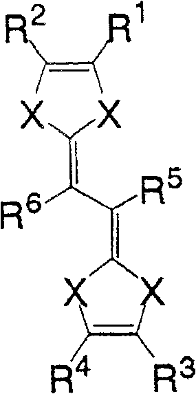
一般式(1):General formula (1):

(式中,X为氮原子,R1~R4各自为独立的链状饱和或不饱和脂肪基、环状的饱和或不饱和脂肪基、氢原子、羟基、氰基、氨基、硝基或亚硝基;R5、R6各自为独立的链状饱和或不饱和脂肪基、环状的饱和或不饱和脂肪基,脂肪基包含选自氧原子、氮原子、硫原子、硅原子、磷原子、硼原子以及卤素原子中的至少1种。)(In the formula, X is a nitrogen atom, R 1 to R 4 are each independent chain saturated or unsaturated aliphatic groups, cyclic saturated or unsaturated aliphatic groups, hydrogen atoms, hydroxyl groups, cyano groups, amino groups, nitro groups or Nitroso; R 5 , R 6 are each an independent chain saturated or unsaturated aliphatic group, cyclic saturated or unsaturated aliphatic group, and the aliphatic group contains an oxygen atom, a nitrogen atom, a sulfur atom, a silicon atom, a phosphorus atom, boron atom and halogen atom.)
一般式(2):General formula (2):
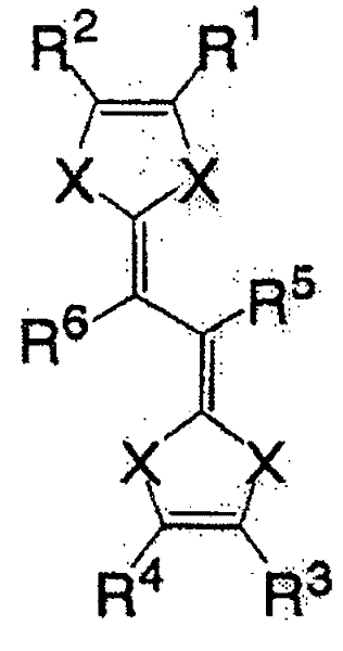
(式中,X为硫原子或氧原子,R1~R4各自为独立的链状饱和或示饱和脂肪基、环状的饱和或不饱和脂肪基、氢原子、羟基、氰基、氨基、硝基或亚硝基;R5、R6各自为独立的链状的饱和或不饱和脂肪基、环状的饱和或不饱和脂肪基,脂肪基包含选自氧原子、氮原子、硫原子、硅原子、磷原子、硼原子以及卤素原子中的至少1种。)(In the formula, X is a sulfur atom or an oxygen atom, R 1 to R 4 are each independent chain saturated or saturated aliphatic groups, cyclic saturated or unsaturated aliphatic groups, hydrogen atoms, hydroxyl groups, cyano groups, amino groups, Nitro or nitroso; R 5 , R 6 are each an independent chain saturated or unsaturated aliphatic group, cyclic saturated or unsaturated aliphatic group, and the aliphatic group contains an oxygen atom, a nitrogen atom, a sulfur atom, At least one of silicon atom, phosphorus atom, boron atom and halogen atom.)
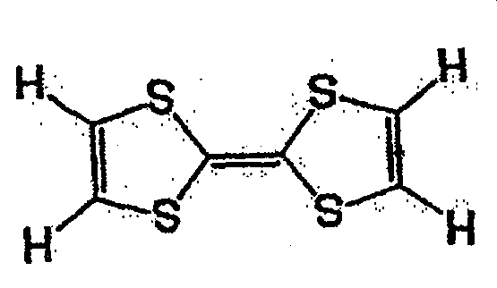
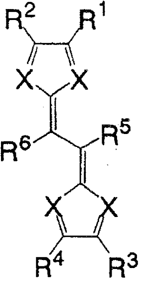
一般式(3):General formula (3):

(式中,R1、R2各自为独立的链状饱和或不饱和脂肪基、环状的饱和或不饱和脂肪基,R1和R2可以相同也可以不同,X为硫原子、氧原子或碲原子,脂肪基包含选自氢原子、氧原子、氮原子、硫原子、硅原子、磷原子、硼原子以及卤素原子中的至少1种。)(wherein, R 1 and R 2 are independently chain saturated or unsaturated aliphatic groups, cyclic saturated or unsaturated aliphatic groups, R 1 and R 2 can be the same or different, X is a sulfur atom, an oxygen atom or a tellurium atom, and the aliphatic group contains at least one selected from a hydrogen atom, an oxygen atom, a nitrogen atom, a sulfur atom, a silicon atom, a phosphorus atom, a boron atom, and a halogen atom.)
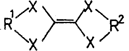
一般式(4):General formula (4):
(式中,X为卤素原子、氢原子、氰基或链状饱和或不饱和脂肪基、环状的饱和或不饱和脂肪基,可以相同也可以不同。)(In the formula, X is a halogen atom, a hydrogen atom, a cyano group or a chain saturated or unsaturated aliphatic group, a cyclic saturated or unsaturated aliphatic group, which may be the same or different.)
一般式(5):General formula (5):
(式中,X为卤素原子、氢原子、氰基或链状饱和或不饱和脂肪基、环状的饱和或不饱和脂肪基,可以相同也可以不同。)(In the formula, X is a halogen atom, a hydrogen atom, a cyano group or a chain saturated or unsaturated aliphatic group, a cyclic saturated or unsaturated aliphatic group, which may be the same or different.)
使用这些材料的话,就能得到能量密度大、能够大电流充放电的二次电池。If these materials are used, a secondary battery having a high energy density and capable of charging and discharging a large current can be obtained.
作为这些以外的这种有机化合物,使用分子内具有硫醇基的有机化合物也能得到能量密度大的二次电池。例如,可举出的有,Ph-S-S-Ph(Ph为苯基)、CH3-S-S-CH3、此外,还可举出苯环上带有氟分子等的二硫化物系材料且分子量小的物质。也可在这种材料中溶解LiBF4、乙基甲基咪唑鎓盐等常温溶融盐等的支持电解质而使用。As such an organic compound other than these, a secondary battery having a high energy density can also be obtained by using an organic compound having a thiol group in the molecule. For example, Ph-SS-Ph (Ph is a phenyl group), CH 3 -SS-CH 3 , and disulfide-based materials with fluorine molecules on the benzene ring, and the molecular weight small matter. Supporting electrolytes such as LiBF 4 and normal temperature molten salts such as ethylmethylimidazolium salts can also be used by dissolving such materials.
图1中,将以有机化合物作为活性物质的液状电极体用于正极、负极两侧。除此以外,也可在正极、负极的至少一侧使用液状电极,另一极使用与传统的二次电池相同的固体活性物质或具有离子嵌入·脱嵌型的活性物质的电极系统。例如,锂金属、石墨材料电极、硅材料电极、锡材料电极可与支持体一起使用。这些电极既可以为包含有锂离子的状态,也可以为不包含的状态,均可适应。In FIG. 1 , a liquid electrode body having an organic compound as an active material is used on both sides of the positive electrode and the negative electrode. In addition, it is also possible to use a liquid electrode on at least one side of the positive electrode and the negative electrode, and use the same solid active material or an electrode system having an ion intercalation/deintercalation type active material as in a conventional secondary battery for the other electrode. For example, lithium metal, graphite material electrodes, silicon material electrodes, tin material electrodes can be used together with the support. These electrodes may be in a state of containing lithium ions or in a state of not containing lithium ions, whichever is applicable.
图3为表示这种电池的一个例子的概略构成图。图3中,与图1相同的构成要素的符号相同,在此省略其说明。电池10A的正极侧的结构与图1所示的电池10相同。负极侧中,负极室14B内使用的是传统的锂二次电池用的负极——石墨的多孔体电极12A。此时,隔离部13以固体电解质构成,与多孔体电极12A紧靠,或者也可以在负极室14B内填充溶解有支持电解质的电解液。FIG. 3 is a schematic configuration diagram showing an example of such a battery. In FIG. 3 , components that are the same as those in FIG. 1 have the same reference numerals, and description thereof will be omitted here. The structure of the positive electrode side of the
此外,图1、图3中所示的正极室14A与负极室14B是单一的,但也可将这些反应室多个串联或并列组合,提高电压和容量。此时,为了避免短路,串联组合的同极性的液状活性物质以各反应室分离。例如在恰当的位置点滴状地设置非连续部。In addition, the
接着对作为活性物质的有机化合物及其反应进行说明。图2为说明本发明实施形态1中的二次电池放电时的反应机理的模式图。正极活性物质氧化体21在与支持电解质离子共存的前提下与存在于正极液20A中的集流体11接触后被还原,成为正极活性物质还原体22。另一方面,负极活性物质还原体24在与支持电解质离子共存的前提下与存在于负极液20B中的集流体12接触后被氧化,成为负极活性物质氧化体23。作为反应生成物的正极活性物质还原体22与负极活性物质氧化体23各自从集流体11和集流体12上立即脱离,再次溶解到存在有支持电解质的正极液20A和负极液20B。此外,充电时进行与此相反的反应。通过这种可逆反应,电池10进行充放电。氧化还原反应中的反应机理随着有机化合物的种类而不同,但氧化体与还原体之间的电化学且可逆的氧化还原反应电位是电动势的基础这一点是共通的。Next, an organic compound as an active material and its reaction will be described. Fig. 2 is a schematic diagram illustrating the reaction mechanism during discharge of the secondary battery in Embodiment 1 of the present invention. The positive electrode active material oxidized
本实施方式中的作为活性物质的有机化合物与传统的重金属系的水溶液相比,在0℃以下的区域至100℃左右的温度范围内,明显高浓度地溶解于溶剂中,由于无需加热等,因此电池的工作温度范围很广。但是,水溶液的情况下,在0℃以下的区域内水会变为固体,因此当然无法溶解活性物质,电池也无法工作。The organic compound as an active material in this embodiment is dissolved in a solvent at a significantly high concentration in a temperature range from below 0° C. to about 100° C. compared with a conventional heavy metal-based aqueous solution. Since no heating is required, Therefore, the operating temperature range of the battery is very wide. However, in the case of an aqueous solution, the water becomes solid in the region below 0°C, so of course the active material cannot be dissolved, and the battery cannot operate.
此外,使用了钒系材料的氧化还原液流电池中,一般在1.5~2mol/L左右的活性物质浓度下使用,但例如,也有如一般式(1)所示的化合物中溶解10mol/L左右。另外,由于钒系活性物质液含有重金属,因此比重较大,约为6g/cm3。与此相对,以有机化合物为活性物质时,为1.0g/cm3左右,电池整体可设计得较轻。In addition, redox flow batteries using vanadium-based materials are generally used at an active material concentration of about 1.5 to 2 mol/L, but for example, compounds represented by the general formula (1) may be dissolved at about 10 mol/L . In addition, since the vanadium-based active material liquid contains heavy metals, it has a large specific gravity of about 6 g/cm 3 . On the other hand, when an organic compound is used as an active material, it is about 1.0 g/cm 3 , and the battery as a whole can be designed to be lighter.
作为这种活性物质的有机化合物,具有π电子共轭云的有机化合物以及分子内含有硫醇基的有机化合物较好。一般式(1)至(3)任意一项所表示的具有π电子共轭云的有机化合物、具有如一般式(4)、(5)中任意一个所示结构的含苯醌系部位的有机化合物的化合物和含有硫醇基的有机化合物,只要能溶解于溶剂中,则可以作为活性物质使用,分子量并无特别限定。其中,特别是具有π电子共轭云的有机化合物的反应速度快、显示出可逆性优异的特性。以下对这些化合物进行说明。首先对具有π电子共轭云的有机化合物进行详细说明。As an organic compound for such an active material, an organic compound having a π-electron conjugated cloud and an organic compound containing a thiol group in the molecule are preferable. An organic compound having a π-electron conjugated cloud represented by any one of the general formulas (1) to (3), an organic compound containing a benzoquinone system having a structure as shown in any one of the general formulas (4) and (5). Compounds and thiol group-containing organic compounds can be used as active substances as long as they are soluble in a solvent, and the molecular weight is not particularly limited. Among them, the organic compound having a conjugated cloud of π electrons has a fast reaction rate and exhibits characteristics of excellent reversibility. These compounds are described below. First, an organic compound having a conjugated cloud of π electrons will be described in detail.
具有π电子共轭云的化合物(以下称为π电子共轭系化合物)是具有较为扁平的分子结构的化合物。该分子由于充放电被氧化或还原的话,基本的分子结构不会改变,π电子云上的电子状态发生变化。因此该分子急速与其附近共存的阴离子或阳离子配位后构成稳定的氧化体或还原体,溶解于溶液中。反之,充电所形成的氧化体或还原体被放电的话,该分子与所配的阴离子或阳离子急速脱离,自行恢复原先的分子状态,溶解于溶液中。A compound having a π-electron conjugated cloud (hereinafter referred to as a π-electron conjugated system compound) is a compound having a relatively flat molecular structure. When this molecule is oxidized or reduced due to charge and discharge, the basic molecular structure does not change, but the state of electrons on the π electron cloud changes. Therefore, the molecule quickly coordinates with the anions or cations that coexist nearby to form a stable oxidant or reductant, which dissolves in the solution. On the contrary, if the oxidized body or reduced body formed by charging is discharged, the molecule will be separated from the anion or cation that it is matched with, and the original molecular state will be restored by itself, and it will be dissolved in the solution.
这种结构中,不存在诸如LiCoO2等层状化合物的伴随阳离子层间移动的扩散阻力。这样,一般式(1)至(3)中任意一项所表示的化合物是理想的快速充放电的材料。为了进行这种反应,π电子共轭系化合物的反应速度快,因此活性物质中使用了这种材料的电池可进行大电流的充放电。显示这种可逆性的π电子系化合物中,特别是具备上述一般式(1)至(3)中任意一项所示结构的化合物,是反应速度和可逆性优异的有机化合物。In this structure, there is no diffusion resistance that accompanies interlayer movement of cations in layered compounds such as LiCoO2 . Thus, the compound represented by any one of the general formulas (1) to (3) is an ideal material for rapid charge and discharge. In order to carry out this reaction, the reaction rate of the π-electron conjugated compound is fast, so a battery using this material as an active material can perform high-current charge and discharge. Among the π-electron compounds exhibiting such reversibility, compounds having a structure represented by any one of the general formulas (1) to (3) above are organic compounds excellent in reaction speed and reversibility.
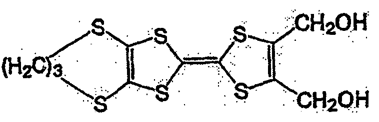
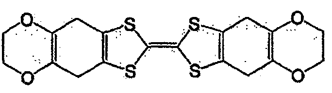
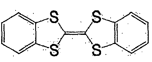
作为一般式(1)、一般式(2)、或一般式(3)所表示的化合物,可举出的有,本发明人在日本公开专利公报特开2004-111374号、特开2004-342605号所公开的化合物。其中,作为一般式(2)所表示的化合物,可举出的有,例如一般式(6)所表示的化合物和式(7)所表示的化合物。As the compound represented by the general formula (1), the general formula (2), or the general formula (3), there can be mentioned the Japanese Laid-Open Patent Publication No. 2004-111374 and Japanese Patent Laid-Open No. 2004-342605. No. disclosed compounds. Among them, as the compound represented by the general formula (2), there may be mentioned, for example, a compound represented by the general formula (6) and a compound represented by the formula (7).
一般式(6):General formula (6):
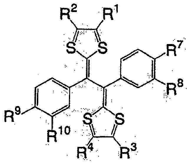
式中,R1~R4以及R7~R10各自为链状的饱和、不饱和脂肪基、环状的饱和、不饱和脂肪基、氢原子、羟基、氰基、氨基、硝基或亚硝基,上述脂肪基包含选自氧原子、氮原子、硫原子、硅原子、磷原子、硼原子以及卤素原子中的至少1种。In the formula, each of R 1 to R 4 and R 7 to R 10 is a chain saturated or unsaturated aliphatic group, a cyclic saturated or unsaturated aliphatic group, a hydrogen atom, a hydroxyl group, a cyano group, an amino group, a nitro group or a nitro group. The nitro group and the aliphatic group include at least one selected from the group consisting of oxygen atom, nitrogen atom, sulfur atom, silicon atom, phosphorus atom, boron atom and halogen atom.
式(7):Formula (7):
式(7)的化合物在一般式(2)的化合物组中分子量小,高容量值得期待。The compound of formula (7) has a small molecular weight among the compound group of general formula (2), and a high capacity is expected.
一般式(6)的化合物组,由于2个5元环近旁存在2个苯环,接近电子从2个5元环转移的能级,犹如进行单电子反应那样的反应。因而,反应速度与一般式(2)的R5、R6不含有苯环的情况相比更快。一般式(6)的化合物的代表例,可举出的有,较好的化合物是式(8)~式(11)所表示的化合物。In general, the compound group of formula (6) has two benzene rings near the two five-membered rings, which is close to the energy level of electron transfer from the two five-membered rings, and reacts as if performing a one-electron reaction. Therefore, the reaction rate is faster than the case where R 5 and R 6 in the general formula (2) do not contain a benzene ring. Representative examples of the compound represented by general formula (6) include compounds represented by formula (8) to formula (11).
式(8)Formula (8)
式(9):Formula (9):
式(10):Formula (10):
式(11):Formula (11):
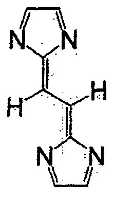
进而,将属于一般式(1)的式(12)的化合物用于活性物质时,由于电位较低,因此可用作负极活性物质。将式(12)的化合物用作负极活性物质时,正极活性物质中可使用例如一般在锂二次电池中所使用的嵌入·脱嵌锂离子的LiCoO2那样的氧化物电极。Furthermore, when the compound of formula (12) belonging to general formula (1) is used as an active material, it can be used as a negative electrode active material because of its low potential. When the compound of formula (12) is used as the negative electrode active material, for example, an oxide electrode such as LiCoO 2 which intercalates and deintercalates lithium ions generally used in lithium secondary batteries can be used as the positive electrode active material.
式(12)Formula (12)
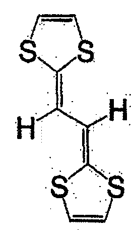
接着,说明一般式(3)所表示的化合物。一般式(3)中,作为R1和R2的脂肪基并无特别限制,但碳原子数1~6的脂肪基较好。特别是,一般式(3)选择脂肪基较好,以形成2个环状π电子系以双键连接的结构。Next, the compound represented by the general formula (3) will be described. In the general formula (3), the aliphatic groups used as R1 and R2 are not particularly limited, but aliphatic groups having 1 to 6 carbon atoms are preferred. In particular, an aliphatic group is preferably selected for the general formula (3) so as to form a structure in which two cyclic π-electron systems are connected by a double bond.
具有一般式(3)所示结构的化合物中,例如有一般式(13)所表示的化合物。Among the compounds having the structure represented by the general formula (3), there are, for example, compounds represented by the general formula (13).
一般式(13)General formula (13)
式中,R3~R6各自为独立的链状或环状的饱和、不饱和脂肪基、氢原子、羟基、氰基、氨基、硝基或亚硝基;R3~R6既可相同也可不同,脂肪基包含选自氧原子、氮原子、硫原子、硅原子、磷原子、硼原子以及卤素原子中的至少1种。In the formula, each of R 3 ~ R 6 is an independent chain or cyclic saturated or unsaturated aliphatic group, hydrogen atom, hydroxyl, cyano, amino, nitro or nitroso; R 3 ~ R 6 can be the same Alternatively, the aliphatic group may contain at least one selected from an oxygen atom, a nitrogen atom, a sulfur atom, a silicon atom, a phosphorus atom, a boron atom, and a halogen atom.
具有一般式(13)所表示的结构的化合物中,作为脂肪基,可举出的有,例如,烷基、环烷基、烷氧基、羟烷基、硫代烷基、醛基、羧基、卤代烷基等,包含如式(14)、式(15)、式(16)、一般式(17)、一般式(18)、一般式(19)的化合物。Among the compounds having a structure represented by the general formula (13), examples of the aliphatic group include an alkyl group, a cycloalkyl group, an alkoxy group, a hydroxyalkyl group, a thioalkyl group, an aldehyde group, a carboxyl group , haloalkyl, etc., including compounds of formula (14), formula (15), formula (16), general formula (17), general formula (18), and general formula (19).
式(14):Formula (14):
式(15):Formula (15):

式(16):Formula (16):
一般式(17):General formula (17):
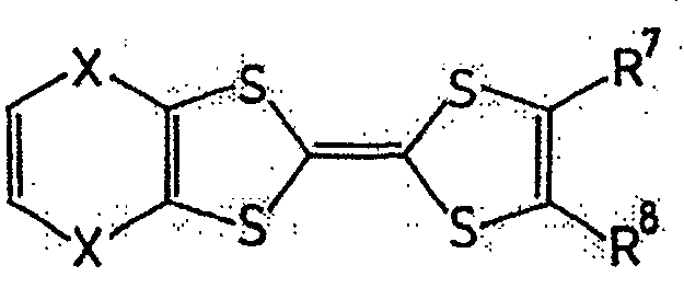
式中,R7及R8各自为独立的链状或环状的饱和、不饱和脂肪基、氢原子、羟基、氰基、氨基、硝基或亚硝基;R7与R8既可相同也可不同,X为硫原子、氧原子、碳原子、或碲原子,上述脂肪基包含选自氧原子、氮原子、硫原子、硅原子、磷原子、硼原子以及卤素原子中的至少1种。In the formula, R 7 and R 8 are independently chained or cyclic saturated or unsaturated aliphatic groups, hydrogen atoms, hydroxyl groups, cyano groups, amino groups, nitro groups or nitroso groups; R 7 and R 8 can be the same It can also be different, X is a sulfur atom, an oxygen atom, a carbon atom, or a tellurium atom, and the above-mentioned aliphatic group contains at least one selected from the group consisting of an oxygen atom, a nitrogen atom, a sulfur atom, a silicon atom, a phosphorus atom, a boron atom, and a halogen atom .
一般式(18):General formula (18):
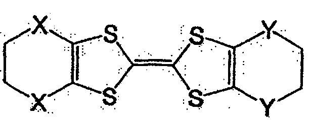
式中,X及Y各自为独立的硫原子、氧原子、碳原子、或甲叉基,X与Y既可相同也可不同。In the formula, X and Y are each an independent sulfur atom, oxygen atom, carbon atom, or methylene group, and X and Y may be the same or different.
一般式(19):General formula (19):
式中,R9及R10各自为独立的链状或环状的饱和、不饱和脂肪基、氢原子、羟基、氰基、氨基、硝基或亚硝基;R9和R10既可相同也可不同,上述脂肪基可包含选自氧原子、氮原子、硫原子、硅原子、磷原子、硼原子以及卤素原子中的至少1种,n为1以上。In the formula, R 9 and R 10 are independently chained or cyclic saturated or unsaturated aliphatic groups, hydrogen atoms, hydroxyl groups, cyano groups, amino groups, nitro groups or nitroso groups; R 9 and R 10 can be the same Alternatively, the aliphatic group may contain at least one selected from an oxygen atom, a nitrogen atom, a sulfur atom, a silicon atom, a phosphorus atom, a boron atom, and a halogen atom, and n is 1 or more.
作为一般式(17)的R7与R8、以及一般式(19)的R9和R10的脂肪基,可举出的有,例如,烷基、环烷基、烷氧基、羟烷基、硫代烷基、醛基、羧基、卤代烷基等。As the aliphatic groups of R 7 and R 8 of the general formula (17) and R 9 and R 10 of the general formula (19), for example, alkyl, cycloalkyl, alkoxy, hydroxyalkane group, thioalkyl group, aldehyde group, carboxyl group, haloalkyl group, etc.
作为相当于一般式(17)的化合物,可举出的有,例如,如式(20)、式(21)、式(22)的化合物。As the compound corresponding to the general formula (17), there may be mentioned, for example, compounds such as the formula (20), the formula (21), and the formula (22).
式(20):Formula (20):
式(21):Formula (21):
式(22):Formula (22):
作为相当于一般式(18)的化合物,可举出的有,例如,如式(23)、式(24)、式(25)的化合物。As the compound corresponding to the general formula (18), there may be mentioned, for example, compounds such as the formula (23), the formula (24), and the formula (25).
式(23):Formula (23):

式(24):Formula (24):

式(25):Formula (25):

作为相当于一般式(19)的化合物,可举出的有,例如,如式(26)的化合物。As the compound corresponding to the general formula (19), there can be mentioned, for example, compounds such as the formula (26).
式(26):Formula (26):
此外,式(27)、式(28)所表示的化合物也属于一般式(13)。In addition, compounds represented by formula (27) and formula (28) also belong to general formula (13).
式(27):Formula (27):
式(28):Formula (28):
具有一般式(3)所表示的结构的化合物中,也可使用具有多个一般式(3)所示结构的高分子化合物。这种化合物具有聚乙炔链作为的主链,可使π电子云扩张,因此较好。Among the compounds having the structure represented by the general formula (3), polymer compounds having a plurality of structures represented by the general formula (3) can also be used. Such a compound is preferable because it has a polyacetylene chain as the main chain and can expand the π electron cloud.
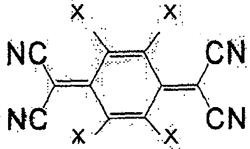
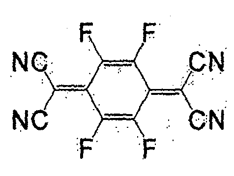
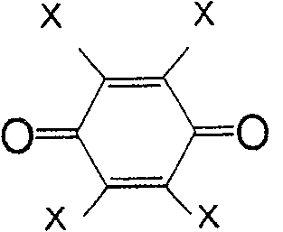
一般式(4)所表示的化合物为苯醌类。取代基X为负电度较高的卤素或氰基较好,氢原子也可。作为属于一般式(4)的化合物,有式(29)、(30)、(31)、(32)、(33)等。The compounds represented by the general formula (4) are benzoquinones. The substituent X is preferably a halogen or a cyano group with a relatively high degree of negative charge, and a hydrogen atom is also acceptable. As the compound belonging to the general formula (4), there are formulas (29), (30), (31), (32), (33) and the like.
式(29):Formula (29):
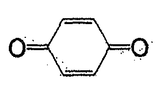
式(30):Formula (30):
式(31):Formula (31):
式(32):Formula (32):

式(33):Formula (33):
一般式(4)中,六元环的对位结合有氧原子,但也可以是邻位结合有氧原子的化合物。作为这种化合物,可举出一般式(34)。作为其具体的例子,可举出式(35)。In the general formula (4), an oxygen atom is bonded to the para-position of the six-membered ring, but a compound in which an oxygen atom is bonded to the ortho-position may also be used. General formula (34) is mentioned as such a compound. As a specific example thereof, formula (35) can be given.
一般式(34)General formula (34)
(式中,R5~R12为质子、氟、或烷基、饱和、不饱和脂肪基,可含有氮、氧、硅,脂肪基既可为直链,也可成环。R5~R12可以相同也可以不同。)(wherein, R5~R12 is proton, fluorine, or alkyl, saturated, unsaturated aliphatic group, can contain nitrogen, oxygen, silicon, and aliphatic group both can be straight chain, also can form ring. R5~R12 can be identical or Can be different.)
式(35):Formula (35):

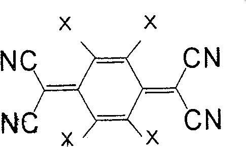
一般式(5)表示的化合物为7,7,8,8-四氰基对苯二醌二甲烷(tetracyano quinodimethane)(TCNQ)的衍生物。取代基X作为正极活性物质使用时,较好的是负电度较高的卤素或氰基,也可为氢原子。此外,作为负极活性物质使用时,较好的是甲基、甲氧基、丁基等。作为属于一般式(5)的化合物,有式(36)、(37)等。The compound represented by the general formula (5) is a derivative of 7,7,8,8-tetracyanoquinodimethane (TCNQ). When the substituent X is used as a positive electrode active material, it is preferably a halogen or a cyano group with a relatively high negative charge, and may also be a hydrogen atom. Moreover, when used as a negative electrode active material, methyl, methoxy, butyl, etc. are preferable. As the compound belonging to the general formula (5), there are formulas (36), (37) and the like.
式(36):Formula (36):
式(37):Formula (37):
接着对分子内含有硫醇基的有机化合物进行说明。其中之一的有机二硫化物化合物是一般的分子内具有如R-S-S-R’(R和R’为脂肪族或芳香族)的-S-S-键的有机化合物。这些有机二硫化物化合物通过氧化,形成S-S间的键被切断的氧化体。即,氧化体是末端具有-SH基或-SLi基等的硫醇类化合物。它们在还原时变成原先的有机二硫化物化合物分子。即,有机二硫化物化合物是还原体。作为有机硫醇类化合物的例子,2,5-二巯基-1,3,4-噻重氮等可溶于溶剂,可作为负极活性物质使用。Next, an organic compound having a thiol group in its molecule will be described. One of the organic disulfide compounds is a general organic compound having an -S-S-bond such as R-S-S-R' (R and R' are aliphatic or aromatic) in the molecule. These organic disulfide compounds are oxidized to form an oxidized body in which the S-S bond is cut. That is, the oxidant is a thiol compound having a -SH group or -SLi group at the end. They become the original organic disulfide compound molecules upon reduction. That is, the organic disulfide compound is a reducing body. As an example of the organic thiol compound, 2,5-dimercapto-1,3,4-thiadiazo, etc. are soluble in a solvent and can be used as a negative electrode active material.
除了这些化合物以外,也可在液体状下溶解支持电解质、或与支持电解质一起溶解于溶剂、氧化还原可逆的有机化合物作为活性物质使用。In addition to these compounds, a redox-reversible organic compound that dissolves the supporting electrolyte in a liquid state or dissolves in a solvent together with the supporting electrolyte can also be used as an active material.
如上所述,本发明的实施形态1的二次电池是工作温度范围广、高输出特性佳、环境负荷小的电池,因此设置场所不受限制。As described above, the secondary battery according to Embodiment 1 of the present invention has a wide operating temperature range, excellent high output characteristics, and low environmental load, so the installation location is not limited.
本实施形态1的电池10中,容器14、槽15A、槽15B各自分离,通过活性物质的输送供给回路(供给部)将其连接,因此各自可设置在有空余的合适位置。此外,这种结构也适用于便携式机器的小型电源。即,将槽15A、槽15B、供给部、以及反应部的容器14设置为盒状等装卸自由形式,可进一步便携化。例如,在电子机器的有限空间内紧凑地收容容器14,可构成从机器的空余空间或从其外部供给活性物质的系统。此外,除了氧化还原液流电池以外,也可构成密闭型的电池。In the
以下根据具体的例子对本实施形态进行进一步详细的说明。但本发明不限定于如下所示的例子。Hereinafter, this embodiment will be further described in detail based on specific examples. However, the present invention is not limited to the examples shown below.
(样品A)(sample A)
作为集流体11、12,使用长30mm、宽10mm、厚5mm形状的石墨烧结体。在隔离正极室14A和负极室14B的隔离部13中使用厚40μm的玻璃纸。使用这些根据图1所示的结构,形成具有以除金属配位化合物、自由基化合物之外的有机化合物为活性物质的液状电极的电池10。作为溶剂,使用的是碳酸甲乙酯和碳酸二乙酯的等体积混合溶剂,作为支持电解质,将LiPF6溶解为1mol/L,配制支持电解质溶液。As the
作为正极活性物质,使用具有π电子共轭云的有机物的式(7)所示的化合物,在上述支持电解质溶液中,将该化合物以10mmol/L的浓度溶解,配制成正极液20A。接着,负极用活性物质使用式(12)的化合物,在上述的支持电解质溶液中,将该化合物以10mmol/L的浓度溶解,配制成负极液20B。接着,将正极液20A、负极液20B各自装入槽15A、15B内,根据上述结构制成电池10。As the positive electrode active material, a compound represented by the formula (7) having an organic substance having a π-electron conjugated cloud was used, and the compound was dissolved in the above-mentioned supporting electrolyte solution at a concentration of 10 mmol/L to prepare a
(样品B)(sample B)
作为正极活性物质,使用具有π电子共轭云的有机物式(28)所示的化合物,作为负极活性物质,使用具有π电子共轭云的有机物式(14)所示的化合物。除此以外与样品A相同地制成样品B的电池10。As the positive electrode active material, a compound represented by the organic compound formula (28) having a π-electron conjugated cloud is used, and as the negative electrode active material, a compound represented by the organic compound formula (14) having a π-electron conjugated cloud is used. The
(样品C)(sample C)
作为正极活性物质,使用有机硫醇化合物2-氨基-4,6-巯基吡啶,将其溶解在与样品A相同的支持电解质溶液中,制成正极液20A。此外,作为负极活性物质,使用液状的有机硫醇化合物2,5-二巯基-1,3,4-噻重氮,作为支持电解质,将LiPF6溶解为1mol/L,制成负极液20B。除此以外与样品A相同地制成样品C的电池10。As the positive electrode active material, an organic thiol compound 2-amino-4,6-mercaptopyridine was used, which was dissolved in the same supporting electrolyte solution as in sample A to prepare a
(样品D)(sample D)
作为正极活性物质,使用具有π电子共轭云的有机物式(32)所示的化合物,作为负极活性物质,使用具有π电子共轭云的有机物式(29)所示的化合物。除此以外与样品A相同地制成样品D的电池10。As the positive electrode active material, a compound represented by the organic compound formula (32) having a π-electron conjugated cloud was used, and as the negative electrode active material, a compound represented by the organic compound formula (29) having a π-electron conjugated cloud was used. The
(样品E)(sample E)
使用传统的锂二次电池用的负极石墨的多孔体电极代替负极集流体12,使用样品A的支持电解质溶液,除此以外与样品B相同地制成样品E的电池10。即,这种结构中,仅在正极活性物质中使用除金属配位化合物和自由基化合物之外的有机化合物。A
(样品F)(sample F)
使用传统的锂二次电池用的正极含有LiCoO2和作为导电材料的碳材料的电极代替正极集流体11,使用样品A的支持电解质溶液,除此以外与样品B相同地制成样品F的电池10。即,这种结构中,仅负极活性物质中使用除金属配位化合物和自由基化合物之外的有机化合物。A battery of sample F was produced in the same manner as sample B except that the positive electrode of a conventional lithium secondary battery was replaced with an electrode containing LiCoO 2 and a carbon material as a conductive material instead of the positive electrode
(比较样品)(comparison sample)
作为正极活性物质,使用硝酰基自由基有机化合物之一的2,2,6,6-四甲基哌啶氧基(テトラメチルピペリジノキシル)自由基衍生物,除此以外与样品E相同地制成比较样品的电池。As the positive electrode active material, 2,2,6,6-tetramethylpiperidinoxy (Tetramethilpiperidinokisil) radical derivative, one of the nitroxyl radical organic compounds, is used, except that it is the same as sample E A battery of a comparative sample was prepared.
上述构成的概要如(表1)所示。The outline of the above configuration is shown in (Table 1).
[表1][Table 1]
接着,对于这些电池,启动泵18A,并根据需要启动泵18B,令供给部工作,以100cm3/分钟的流量令正极液20A、负极液20B循环。在此状态下,对集流体11、12在电流密度10mA/cm2下进行充放电试验。此时,充放电的上限、下限电压如(表1)所示设定。Next, for these batteries, the
其结果是,样品A~F可重复进行50循环以上的充放电。再在充电后停止泵18A和泵18B,即便是放置了30天以上的电池,也几乎没有出现容量的下降。即使是隔离部13使用了玻璃纸,这种程度的充放电循环和放置也没有问题。As a result, samples A to F were able to repeat charging and discharging for 50 cycles or more. Furthermore, when the
与此相对,比较样品的循环和容量均下降,充电后放置的电池随着放置数小时,容量和平坦电压均大幅下降。解析的结果是,这种特性下降的减少不仅因为自由基存在寿命,自由基聚合引起的活性物质成分的减少和集流体表面的阻抗的增加也是原因。此外,由于自由基化合物的大半进行的是单电子反应,因此容量密度小。例如,比较样品使用的化合物的理论容量密度为172mAh/g。与此相对,本实施方式的化合物均为双电子反应。因此容量密度大,作为电池的能量密度大。On the other hand, both the cycle and capacity of the comparative sample decreased, and the capacity and flat voltage of the battery left after charging decreased significantly as it was left for several hours. As a result of the analysis, it was found that the decrease in the characteristic degradation was not only caused by the lifetime of radicals, but also by a decrease in the active material component due to radical polymerization and an increase in the resistance of the current collector surface. In addition, since most of the radical compounds undergo one-electron reactions, the capacity density is small. For example, the theoretical capacity density of the compound used for the comparative sample was 172 mAh/g. On the other hand, the compounds of the present embodiment are all two-electron reactions. Therefore, the capacity density is high, and the energy density as a battery is high.
此外,除样品使用的活性物质以外的实施方式中列举的化合物和液状或可溶于溶剂的具有硫醇基的有机化合物,也得到了同样的结果。In addition, the same results were obtained for the compounds listed in the embodiments and liquid or solvent-soluble organic compounds having a thiol group other than the active material used in the samples.
接着对使用水溶液作为支持电解质溶液的例子进行说明。Next, an example of using an aqueous solution as a supporting electrolyte solution will be described.
(样品K)(sample K)
作为集流体11、12,使用长30mm、宽10mm、厚5mm形状的石墨烧结体。隔离正极室14A和负极室14B的隔离部13中使用厚40μm的玻璃纸。使用这些形成图1所示结构的具有以除金属配位化合物、自由基化合物以外的有机化合物为活性物质的液状电极的电池10。作为支持电解质,调制将LiCl溶解为1mol/L的水溶液。As the
作为正极活性物质,使用具有π电子共轭云的有机物式(36)所示的化合物,在上述的支持电解质溶液中,将该化合物以10mmol/L的浓度溶解,调制成正极液20A。接着,负极用活性物质使用式(14)的化合物,在上述的支持电解质溶液中,将该化合物以10mmol/L的浓度溶解,调制成负极液20B。接着,将正极液20A、负极液20B各自装入槽15A、15B内,根据上述结构制成电池10。As the positive electrode active material, a compound represented by the organic formula (36) having a π-electron conjugated cloud was used, and the compound was dissolved in the above-mentioned supporting electrolyte solution at a concentration of 10 mmol/L to prepare a
(样品L)(sample L)
作为正极活性物质,使用具有π电子共轭云的有机物式(37)所示的化合物,作为负极活性物质,使用具有π电子共轭云的有机物式(36)所示的化合物。除此以外与样品K相同地制成样品L的电池10。As the positive electrode active material, a compound represented by the organic compound formula (37) having a π-electron conjugated cloud was used, and as the negative electrode active material, a compound represented by the organic compound formula (36) having a π-electron conjugated cloud was used. The
(样品M)(sample M)
作为正极活性物质,使用具有π电子共轭云的有机物式(30)所示的化合物,作为负极活性物质,使用具有π电子共轭云的有机物式(29)所示的化合物。作为支持电解质溶液,使用HNO3溶解为2mol/L的水溶液。除此以外与样品K相同地制成样品M的电池10。As the positive electrode active material, a compound represented by the organic compound formula (30) having a π electron conjugated cloud is used, and as the negative electrode active material, a compound represented by the organic compound formula (29) having a π electron conjugated cloud is used. As the supporting electrolyte solution, an aqueous solution in which HNO 3 was dissolved to 2 mol/L was used. The
(样品N)(sample N)
作为正极活性物质,使用具有π电子共轭云的有机物式(25)所示的化合物,作为负极活性物质,使用具有π电子共轭云的有机物式(35)所示的化合物。作为支持电解质溶液,使用HNO3溶解为2mol/L的水溶液。除此以外与样品K相同地制成样品N的电池10。As the positive electrode active material, a compound represented by the organic formula (25) having a π-electron conjugated cloud is used, and as the negative electrode active material, a compound represented by the organic compound formula (35) having a π-electron conjugated cloud is used. As the supporting electrolyte solution, an aqueous solution in which HNO 3 was dissolved to 2 mol/L was used. The
上述构成的概要如(表2)所示。The outline of the above configuration is shown in (Table 2).
[表2][Table 2]
接着,对各电池进行与样品A相同的评价。此时,充放电的上限、下限电压如(表2)所示设定。这些样品也可重复进行50次循环以上的充放电。再在充电后停止泵18A和泵18B,即便是放置了30天以上的电池,也几乎没有出现容量的下降。即使是隔离部13使用了玻璃纸,这种程度的充放电循环和放置也没有问题。Next, the same evaluation as the sample A was performed on each battery. At this time, the upper and lower limit voltages of charging and discharging were set as shown in (Table 2). These samples were also repeatable for more than 50 cycles of charge and discharge. Furthermore, when the
(实施方式2)(Embodiment 2)
接着,对使用了实施方式1所说明的二次电池的电源系统进行说明。图4为复合了本发明实施方式1的二次电池和对二次电池供给电力的电源——燃料电池的电源系统的概念图。Next, a power supply system using the secondary battery described in Embodiment 1 will be described. 4 is a conceptual diagram of a power supply system combining a secondary battery according to Embodiment 1 of the present invention and a fuel cell, which is a power supply for supplying electric power to the secondary battery.
燃料电池31的正极端子32与电池10的正极端子11T、负极端子33与负极端子12T各自连接,均连接在负荷34上。即,燃料电池31与电池10并联连接。电池10具有图1所示的结构,在此省略其说明。此外,图中虽未标示,但电池10和燃料电池31之间设置有调整充电电压的调节器,进而在任意一处设置可选择回路的开闭器较好。The
该电源系统中,电池10处于时常从燃料电池31充电的状态,对于负荷34,可以从燃料电池31和电池10双方供给电力。对于负荷34的电力,燃料电池31的输出不足时,电池10可供给电力。即,负荷34的电的大小发生变化时,至燃料电池对应负荷变动的这期间,由电池10向负荷34辅助供给电力。燃料电池31对应负荷变动后,仅由燃料电池31对负荷34供给电力,与此同时,燃料电池31向电池10充电。这样,电池10的残存容量维持在一定容量。In this power supply system, the
一般,燃料电池输出一定的固定电力是最有效率的。电池10对变动的负荷34发挥peakcut功能和储存能源的作用。这样,燃料电池31得到有效地利用。此外,由于电池10具有高输出性,因此该电源系统可形成为紧凑盒状。再将槽15A、15B和作为充放电部的容器14分离的话,即可设置于任意环境下。Generally, it is most efficient for a fuel cell to output a certain fixed amount of electricity. The
接着,参照图5,对其他构造的电源系统进行说明。在此省略与图4相同部分的说明。电池10和燃料电池31之间设置有开闭器35。电池10和负荷34之间设置有负荷电流检测器36。图中虽未标示,但在燃料电池31内部,设置有用于检测燃料电池31的状态的装置,从燃料电池31向燃料电池控制装置37传送状态检测信号39。燃料电池控制装置37接受负荷电流检测器36的输出信号和燃料电池31的状态检测信号39,向开闭器35和燃料电池31发送控制信号38。此外,电池10中预先从燃料电池31处积蓄了一定的能量。Next, a power supply system with another structure will be described with reference to FIG. 5 . The description of the same parts as those in FIG. 4 is omitted here. A
以下说明上述结构中燃料电池31与负荷变动相对应时各部件的工作。负荷电流检测器36检测出流向负荷34的电流。负荷电流检测器36将检测出的对应负荷电流的信号传输至燃料电池控制装置37。基于此信号,燃料电池控制装置37判断是否有负荷变动。判断为有负荷变动时,燃料电池控制装置37向燃料电池31和开闭器35传送控制信号38。The operation of each component when the
燃料电池31收到控制信号38后,为应对负荷变动而改变燃料的供给量。但是,将燃料供给到作为燃料电池31的反应场的膜整体需要一定的时间。此外,开闭器35在收到控制信号38后打开回路。然后,仅由电池10向负荷34供给电力。这样,即便在燃料电池31供给与负荷34相应的燃料期间,也可以排除对于燃料电池31的输出下降和换极等影响。After receiving the
此外,当燃料电池控制装置37从来自于燃料电池31的信号39判断出处于能够与负荷电流相对应的状态时,燃料电池控制装置37向开闭器35发出控制信号38,关闭开闭器35。这样,当燃料电池31对应负荷34的变动后,仅由燃料电池31向负荷34供给电力,同时,电池10对所消耗的能量进行充电。In addition, when the fuel
这样,可以防止输出电压的急剧减少或换极,提高燃料电池的寿命和可信任性,提高系统整体的稳定性、维修性。In this way, a sudden decrease in output voltage or pole change can be prevented, the life and reliability of the fuel cell can be improved, and the stability and maintainability of the entire system can be improved.
接着参照图6,对另一结构的电源系统进行说明。在此省略与图4和图5相同部分的说明。该构成中,设置有限制输出的调节器351来代替图5中的开闭器35。燃料电池控制装置37接受负荷电流检测器36的输出信号和燃料电池31的状态检测信号39,向调节器351和燃料电池31发出控制信号38。此外,电池10中预先从燃料电池31处积蓄了一定的能量。Next, referring to FIG. 6 , a power supply system with another configuration will be described. The description of the same parts as those in FIG. 4 and FIG. 5 is omitted here. In this configuration, an output-limiting
以下说明上述结构中燃料电池31对应负荷变动时各部件的工作。负荷电流检测器36检测出流向负荷34的电流。负荷电流检测器36将检测出的对应负荷电流的信号传输至燃料电池控制装置37。基于此信号,燃料电池控制装置37判断是否有负荷变动。判断为有负荷变动时,燃料电池控制装置37向燃料电池31和调节器351传送控制信号38。The operation of each component when the
燃料电池31收到控制信号38后,为对应负荷变动而改变燃料的供给量。但是,将燃料供给到作为燃料电池31的反应场的膜整体需要一定的时间。在此期间,仅由燃料电池维持向负荷34供给电力。因此,不足部分的电流由电池10供给。当燃料电池控制装置37接收到燃料电池31的状态检测信号39后,向控制器351发出控制信号38,限制燃料电池31的输出。当燃料电池控制装置37基于信号39,判断出燃料电池31处于可应对负荷电流状态时,燃料电池控制装置37向调节器351发出控制信号38,解除燃料电池31的输出限制。After receiving the
通过以上顺序来对应负荷变动,可在燃料电池31根据负荷34而供给燃料的期间内,排除燃料电池31的输出下降和换极的影响。在此期间,电池10补充燃料电池31的输出,向负荷34供给电力。当燃料电池31对应负荷34的变动后,仅由燃料电池31向负荷34供给电力,同时,电池10对所消耗的能量进行充电。此时,由于负荷变动时电池10放出的能量减少,因此作为系统整体产生了用于应对输出变动的最大值的空余。By responding to load fluctuations in the above procedure, it is possible to eliminate the effects of output drop and pole change of the
这样,可以防止输出电压的急剧减少或换极,提高燃料电池的寿命和可信任性,提高系统整体的稳定性、维修性。此外,当应该对应的负荷电流的最大值相同的情况下,可减少应搭载的电池10的容量或个数,可削减整体成本。In this way, a sudden decrease in output voltage or pole change can be prevented, the life and reliability of the fuel cell can be improved, and the stability and maintainability of the overall system can be improved. In addition, when the maximum value of the load current to be supported is the same, the capacity or the number of
如上所述,本实施方式下的电源系统中,当负荷34超过了作为电源的燃料电池31的电力供给能力时,不足部分的电力由电池10向负荷34供给。然后,当燃料电池31可以供给对应于负荷34的电力后,电池10进行充电,将电池10的残存容量维持在一定的容量。As described above, in the power supply system according to the present embodiment, when the
此外,正常运转时,由燃料电池31向负荷34供给电力。然后,较好的是当负荷34低于燃料电池31的电力供给能力时,利用燃料电池31的剩余电力对电池10充电。这样,可以有效利用燃料电池的发电能力。此外,不使燃料电池31发生输出变动的情况下发电效率较好,因此较好的是能这样控制运转。In addition, during normal operation, electric power is supplied from the
(实施方式3)(Embodiment 3)
接着,对使用了实施方式1所述的二次电池的其他电源系统进行说明。图7为复合了电池10和太阳能电池41的电源系统的概念图。太阳能电池41的正极端子42与电池10的正极端子11T连接、负极端子43与负极端子12T连接,均连接在负荷34上。电池10具有图1所示的结构,在此省略其说明。此外,图中虽未标示,但较好的是,电池10和太阳能电池41之间设置有调整充电电压的调节器,进而在任意一处设置可选择回路的开闭器。Next, another power supply system using the secondary battery described in Embodiment 1 will be described. FIG. 7 is a conceptual diagram of a power supply system in which
该电源系统中,电池10处于经常从太阳能电池41充电的状态,但一般太阳能电池会随着天气气候和时间等的光照射状况,改变输出。该电源系统中,对于负荷34,太阳能电池41的输出不足时,电池10放电,填补电力。当太阳能电池41的输出对于负荷34有余力时,电池10进行充电。这样,输出变动的太阳能电池41可得到有效利用。特别是由于太阳能电池41设置于室外环境中,工作温度范围较广的电池10是电力系统的较好补充设备。In this power supply system, the
接着参照图8,对其他结构的电源系统进行说明。在此省略与图7相同部分的说明。图中虽未标示,但在电池10与太阳能电池41之间,设置有调整充电电压的调节器,进而在太阳能电池41与电池10之间设置有开闭器35或调节器(未图示)。此外,还设置有把握电池10的充电状态、对源自于太阳能电池41的充电进行控制的控制部47。Next, a power supply system with another configuration will be described with reference to FIG. 8 . The description of the same parts as those in FIG. 7 is omitted here. Although not shown in the figure, a regulator for adjusting the charging voltage is provided between the
该电源系统中,对于负荷34,太阳能电池41的输出不足时,电池10放电,填补电力,当太阳能电池41的输出对于负荷34有余力时,电池10进行充电。在这里,电池10根据其充电状态,通过由控制部47所控制的开闭器35或调节器的工作,从太阳能电池41进行充电,无负荷状态下,控制为满充电状态。当控制部47判断电池10充电已满、且无负荷34时,在日照持续的情况下,控制开闭器35或调节器,停止充电。In this power supply system, when the output of the
另外,向负荷34供给电力时,控制部47通过开闭器35隔断源自太阳能电池41的电力,或通过调节器进行调节。这样,仅由电池10对负荷34供给电力。或者,通过由电池10来补助供给太阳能电池41发电不足的电力,此时,可以向负荷34供给不受日照量左右的稳定的电力。Moreover, when electric power is supplied to the
这样,输出有变动的太阳能电池41可得到有效利用。电池10可有效积蓄随日照量剧烈变化的太阳能电池的输出。特别是由于太阳能电池41设置于室外环境中,工作温度范围较广的电池10成为电力系统的较好补充设备。In this way, the
此外,该系统中,当日照量产生的充电电量超过了消耗的电量时,存在电池10过放电的问题。因此,可以组合使用以辅助和备用为目的的商用电源。通过这种结构,在节约电费的同时,可有效地利用太阳能电池41的发电电力,构筑稳定的电源系统。In addition, in this system, when the charging power generated by the amount of sunlight exceeds the consumed power, there is a problem of over-discharging of the
如上所述,本实施方式下的电源系统中,当负荷34超过了作为电源的太阳能电池41的电力供给能力时,电池10向负荷34供给不足部分的电力。然后,当太阳能电池41可以供给对应于负荷34的电力后,电池10进行充电,将电池10的残存容量维持在一定的容量。As described above, in the power supply system according to the present embodiment, when the
此外,当负荷34低于太阳能电池41的电力供给能力时,较好的是利用太阳能电池41的剩余电力对电池10充电。这样,可以有效利用太阳能电池41的发电能力。Furthermore, when the
(实施方式4)(Embodiment 4)
接着,对使用了实施方式1所述的二次电池的另一电源系统进行说明。图9为复合了电池10和商用电池51的电源系统的概念图。交流的商用电源51连结在具有将交流变为直流的功能的整流器、或变流器等的整流回路54上。整流回路54在输出一侧具有正极端子52和负极端子53。正极端子52与电池10的正极端子11T连接、负极端子53与负极端子12T连接,均连接在负荷34上。即,连接于商用电源51的整流回路54与电池10并联连接。另外,电池10具有图1所示的结构,因此在此省略其说明。此外,图中虽未标示,但电池10和整流回路54之间设置有调整充电电压的调节器,进而在任意一处设置可选择回路的开闭器较好。Next, another power supply system using the secondary battery described in Embodiment 1 will be described. FIG. 9 is a conceptual diagram of a power supply system in which
该电源系统中,通过恒流方式或恒压方式,电池10处于经常从商用电源51处充电的状态。电池10积蓄商用电源51的电力,发挥着应对停电等非常状态,或应对负荷34瞬时增大等作用。即,当负荷34的大小变化时,直至商用电源51能够对应负荷变动的期间,由电池10向负荷34辅助供给电力。商用电源51对应负荷变动后,仅由商用电源51对负荷34供给电力,与此同时,商用电源51向电池10充电。高输出特性优异的电池10在这种复合系统中成为有效的补充设备。或者,在夜晚、春秋季等电力需求较少的时间段、季节中电池10主要进行充电,在白天、夏冬季等电力需求较多的时间段、季节中电池10主要进行放电。这样的话,可以帮助稳定电力的负荷。In this power supply system, the
接着参照图10,对又一其他方式的电源系统进行说明。在此省略与图9相同部分的说明。图中虽未标示,但在电池10和整流回路54之间设置有调整充电电压的调节器。电池10和整流回路54之间设置有开闭器35或调节器(未图示)。调节器与图6的调整器351相同。此外,还设置有把握电池10的充电状态、对来自商用电源51的充电进行控制的控制部57。此外,开闭器35或调节器上同时设有电流测定功能、向控制部57发送电流信号较为理想。Next, a power supply system in still another form will be described with reference to FIG. 10 . The description of the same parts as those in FIG. 9 is omitted here. Although not shown in the figure, a regulator for adjusting the charging voltage is provided between the
该电源系统中,根据电池10的充电状态,控制部57控制开闭器35或调节器。通过开闭器35或调节器的工作,电池10通过恒电流方式或恒压方式,从商用电源51处充电。当电池10处于无负荷状态时,控制为满充电状态。In this power supply system, the
当控制部57接收到源自电池10的信号、判断到电池10满充电、且无负荷时,控制开闭器35或调节器,停止充电。当负荷34处于断路器的容许范围内时,控制部57在维持电池10充电状态的同时向负荷34供给电力。通过这种调节,电池10积蓄商用电源51的电力,应对停电等非常状态,供给电力。或者,当负荷34暂时超出断路器的容许范围,发生变动时,电池10向负荷34辅助供给电力。当商用电源51对应负荷变动后,由商用电源51向负荷34供给电力,商用电源51向电池10充电。When the
此外,较为理想的是:通过同时设置在开闭器35或调节器的电流测定功能,控制部57对开闭器35或调节器进行控制从而不超出断路器的容许值。通过这种控制,商用电源51可供给最大电力,同时由电池10补充不足的部分。In addition, it is preferable that the
高输出特性优异的电池10在这种复合系统中,通过快速地将消耗的能源进行充电,可以针对反复的停电供给稳定的电力。此外,高输出特性优异的电池10在这种复合系统中,针对负荷的暂时激增,可以通过更小容量的电池10,应对过渡性的负荷变动,供给稳定的电力。此时不会出现超出断路器的容量界限、阻断电力供给的情况。The
或者,高输出特性优异的电池10在这种复合系统中,在夜晚、春秋季等电力需求较少的时间段、季节中主要进行充电,在白天、夏冬季等电力需求较多的时间段、季节中主要进行放电。这样的话,电池10可以有助于均衡电力负荷。这样,高输出特性优异的电池10在这种复合系统中成为有效的补充设备。即,当负荷34低于商用电源51的电力供给能力时,通过商用电源51的剩余电力对电池10进行充电较好。Alternatively, in such a composite system, the
上述本实施方式中的电源系统中,当负荷34超过电源——商用电源51的电力供给能力时,由电池10对负荷34的不足部分供给电力。当商用电源51能够供给与负荷34相对应的电力后,电池10进行充电,以使电池10的残余容量维持在一定的容量。In the power supply system in the present embodiment described above, when the
上述实施方式1中的电池10不包含重金属作为配位化合物,环境负荷性优异,且能发挥良好的寿命特性。此外,通过如实施方式2~4,构成燃料电池31、太阳能电池41、商用电力51的复合电力系统,可以填补其他电力系统(电源)的缺点,有效发挥各自的特征。即,当负荷变动超过本发明的二次电池以外的电源的电力供给能力时,或者电源的电力供给能力下降、对负荷不充分时,二次电池向负荷供给不足部分的电力。The
此外,实施方式2~4各自为燃料电池31、太阳能电池41、商用电源51的任意一个与电池10的组合,但也可混合电池以外的电源。In addition, Embodiments 2 to 4 are each a combination of any one of the
在接近满充电状态下,电池10中容易出现电池反应以外的副反应。因此,这种状态长期维持的话,电池10的特性会下降。因而,在实施方式2~4所说明的电源系统中,当达到规定的充电深度(残存容量)以上时,控制部37、47、57使电池10放电、降低充电深度较好。即,维持电池10的残存容量在一定容量较好。这样可以延长电池10的寿命,抑制循环退化。此外,这种控制也可适用于上述实施方式3的电源系统和实施方式4的电源系统。In a state close to full charge, side reactions other than battery reactions tend to occur in the
工业实用性Industrial Applicability
本发明的二次电池安全且寿命长,不仅对便携性和改进电子机器的搭载性有效,还有望用作为电动汽车等的移动电源、能量储藏和电力平稳化等小型至大型的新型电源。The secondary battery of the present invention is safe and has a long life, and is not only effective for portability and improvement of the mountability of electronic devices, but also is expected to be used as a mobile power source for electric vehicles, energy storage, and power stabilization, and other small to large new power sources.
Claims (8)
Applications Claiming Priority (3)
| Application Number | Priority Date | Filing Date | Title |
|---|---|---|---|
| JP2005158701 | 2005-05-31 | ||
| JP158701/2005 | 2005-05-31 | ||
| PCT/JP2006/310728 WO2006129635A1 (en) | 2005-05-31 | 2006-05-30 | Secondary battery, power supply system using same and usage of power supply system |
Publications (2)
| Publication Number | Publication Date |
|---|---|
| CN101185185A CN101185185A (en) | 2008-05-21 |
| CN101185185B true CN101185185B (en) | 2010-04-07 |
Family
ID=37481564
Family Applications (1)
| Application Number | Title | Priority Date | Filing Date |
|---|---|---|---|
| CN200680018818XA Active CN101185185B (en) | 2005-05-31 | 2006-05-30 | Secondary battery, power supply system using same, and method for using power supply system |
Country Status (4)
| Country | Link |
|---|---|
| US (1) | US20090017379A1 (en) |
| JP (1) | JP5050847B2 (en) |
| CN (1) | CN101185185B (en) |
| WO (1) | WO2006129635A1 (en) |
Families Citing this family (78)
| Publication number | Priority date | Publication date | Assignee | Title |
|---|---|---|---|---|
| US8277964B2 (en) | 2004-01-15 | 2012-10-02 | Jd Holding Inc. | System and method for optimizing efficiency and power output from a vanadium redox battery energy storage system |
| JP5110625B2 (en) * | 2007-02-02 | 2012-12-26 | パナソニック株式会社 | Electricity storage device |
| US7517608B2 (en) * | 2007-03-09 | 2009-04-14 | Vrb Power Systems Inc. | Inherently safe redox flow battery storage system |
| JP5211775B2 (en) * | 2008-03-14 | 2013-06-12 | 株式会社豊田中央研究所 | Slurry secondary battery |
| US8722226B2 (en) | 2008-06-12 | 2014-05-13 | 24M Technologies, Inc. | High energy density redox flow device |
| US11909077B2 (en) | 2008-06-12 | 2024-02-20 | Massachusetts Institute Of Technology | High energy density redox flow device |
| EP2297810B1 (en) * | 2008-06-12 | 2014-12-24 | Massachusetts Institute of Technology | High energy density redox flow device |
| US9786944B2 (en) | 2008-06-12 | 2017-10-10 | Massachusetts Institute Of Technology | High energy density redox flow device |
| US7820321B2 (en) * | 2008-07-07 | 2010-10-26 | Enervault Corporation | Redox flow battery system for distributed energy storage |
| US8785023B2 (en) * | 2008-07-07 | 2014-07-22 | Enervault Corparation | Cascade redox flow battery systems |
| JP2010086935A (en) * | 2008-09-03 | 2010-04-15 | Sharp Corp | Redox flow battery |
| KR20110084980A (en) * | 2008-11-04 | 2011-07-26 | 캘리포니아 인스티튜트 오브 테크놀로지 | Hybrid Electrochemical Generator with Water Soluble Anode |
| JP2010170782A (en) * | 2009-01-21 | 2010-08-05 | Sharp Corp | Redox flow battery, and method of charging and discharging the same |
| DE102009009357B4 (en) * | 2009-02-18 | 2011-03-03 | Fraunhofer-Gesellschaft zur Förderung der angewandten Forschung e.V. | Redox flow battery for storing electrical energy in ionic liquids |
| JP5882888B2 (en) * | 2009-04-06 | 2016-03-09 | 24エム・テクノロジーズ・インコーポレイテッド24M Technologies, Inc. | Fuel system using redox flow battery |
| JP2010244972A (en) * | 2009-04-09 | 2010-10-28 | Sharp Corp | Redox flow battery |
| US8460814B2 (en) * | 2009-07-29 | 2013-06-11 | The Invention Science Fund I, Llc | Fluid-surfaced electrode |
| US20110027637A1 (en) * | 2009-07-29 | 2011-02-03 | Searete Llc, A Limited Liability Corporation Of The State Of Delaware | Fluid-surfaced electrode |
| US20110027638A1 (en) * | 2009-07-29 | 2011-02-03 | Searete Llc, A Limited Liability Corporation Of The State Of Delaware | Fluid-surfaced electrode |
| US8865361B2 (en) * | 2009-07-29 | 2014-10-21 | The Invention Science Fund I, Llc | Instrumented fluid-surfaced electrode |
| US8889312B2 (en) | 2009-07-29 | 2014-11-18 | The Invention Science Fund I, Llc | Instrumented fluid-surfaced electrode |
| US10074879B2 (en) | 2009-07-29 | 2018-09-11 | Deep Science, Llc | Instrumented fluid-surfaced electrode |
| WO2011058873A1 (en) * | 2009-11-12 | 2011-05-19 | 独立行政法人産業技術総合研究所 | Positive electrode active material for nonaqueous secondary battery |
| US20110274948A1 (en) * | 2010-04-09 | 2011-11-10 | Massachusetts Institute Of Technology | Energy transfer using electrochemically isolated fluids |
| US9300012B2 (en) * | 2010-05-31 | 2016-03-29 | Hiroshi Ohkawa | Solid electrolyte secondary battery |
| US10651492B2 (en) | 2010-06-22 | 2020-05-12 | Vrb Energy Inc. | Integrated system for electrochemical energy storage system |
| KR101747862B1 (en) * | 2010-11-03 | 2017-06-16 | 삼성전자주식회사 | Redox flow battery |
| US8709629B2 (en) | 2010-12-22 | 2014-04-29 | Jd Holding Inc. | Systems and methods for redox flow battery scalable modular reactant storage |
| KR101793206B1 (en) * | 2010-12-31 | 2017-11-03 | 삼성전자 주식회사 | Redox flow battery |
| KR101793205B1 (en) * | 2010-12-31 | 2017-11-03 | 삼성전자 주식회사 | Redox flow battery |
| KR101819036B1 (en) * | 2010-12-31 | 2018-01-17 | 삼성전자주식회사 | Redox flow battery |
| WO2012097286A1 (en) | 2011-01-13 | 2012-07-19 | Deeya Energy, Inc. | Flow cell stack |
| JP5007849B1 (en) | 2011-03-25 | 2012-08-22 | 住友電気工業株式会社 | Redox flow battery and operation method thereof |
| US8916281B2 (en) | 2011-03-29 | 2014-12-23 | Enervault Corporation | Rebalancing electrolytes in redox flow battery systems |
| US8980484B2 (en) | 2011-03-29 | 2015-03-17 | Enervault Corporation | Monitoring electrolyte concentrations in redox flow battery systems |
| KR101882861B1 (en) * | 2011-06-28 | 2018-07-27 | 삼성전자주식회사 | Electrolyte for Redox Flow Battery and Redox Flow Battery Comprising the same |
| US10141594B2 (en) | 2011-10-07 | 2018-11-27 | Vrb Energy Inc. | Systems and methods for assembling redox flow battery reactor cells |
| KR101890747B1 (en) * | 2011-11-03 | 2018-10-01 | 삼성전자주식회사 | Ion conductor filling composition, method of preparing ion exchange membrane, ion exchange membrane and redox flow battery |
| US9853454B2 (en) | 2011-12-20 | 2017-12-26 | Jd Holding Inc. | Vanadium redox battery energy storage system |
| US9300000B2 (en) * | 2012-02-28 | 2016-03-29 | Uchicago Argonne, Llc | Organic non-aqueous cation-based redox flow batteries |
| US9966625B2 (en) * | 2012-02-28 | 2018-05-08 | Uchicago Argonne, Llc | Organic non-aqueous cation-based redox flow batteries |
| US9484569B2 (en) | 2012-06-13 | 2016-11-01 | 24M Technologies, Inc. | Electrochemical slurry compositions and methods for preparing the same |
| IN2015DN03105A (en) * | 2012-09-26 | 2015-10-02 | Harvard College | |
| US9362583B2 (en) | 2012-12-13 | 2016-06-07 | 24M Technologies, Inc. | Semi-solid electrodes having high rate capability |
| US8993159B2 (en) | 2012-12-13 | 2015-03-31 | 24M Technologies, Inc. | Semi-solid electrodes having high rate capability |
| US8993183B2 (en) | 2012-12-31 | 2015-03-31 | Enervault Corporation | Operating a redox flow battery with a negative electrolyte imbalance |
| US8980454B2 (en) | 2013-03-15 | 2015-03-17 | Enervault Corporation | Systems and methods for rebalancing redox flow battery electrolytes |
| KR20160008594A (en) * | 2013-05-16 | 2016-01-22 | 유나이티드 테크놀로지스 코포레이션 | Flow battery with hydrated ion-exchange membrane having maximum water domain cluster sizes |
| US9614245B2 (en) | 2013-06-17 | 2017-04-04 | University Of Southern California | Inexpensive metal-free organic redox flow battery (ORBAT) for grid-scale storage |
| DE102013217858A1 (en) * | 2013-09-06 | 2015-03-12 | Acal Energy Ltd. | Fuel cell system, motor vehicle containing a fuel cell system and method for operating a fuel cell system |
| AU2014324647B2 (en) | 2013-09-26 | 2018-12-20 | President And Fellows Of Harvard College | Quinone and hydroquinone based flow battery |
| TWI506292B (en) * | 2013-10-28 | 2015-11-01 | Inst Nuclear Energy Res Atomic Energy Council | Device of Detecting Charging/Discharging States of Flow Battery by Using Ultrasonic Wave |
| CN106229537A (en) * | 2014-02-13 | 2016-12-14 | 天津大学 | Flow battery based on organic halogen electrolyte |
| EP3316375B1 (en) * | 2015-06-23 | 2020-03-18 | Panasonic Intellectual Property Management Co., Ltd. | Redox flow cell |
| FR3042650A1 (en) * | 2015-10-20 | 2017-04-21 | Commissariat Energie Atomique | REDOX ELECTROLYTE CIRCULATION BATTERY COMPRISING SPECIFIC ELECTROLYTES |
| US11005087B2 (en) | 2016-01-15 | 2021-05-11 | 24M Technologies, Inc. | Systems and methods for infusion mixing a slurry based electrode |
| JP2017134920A (en) * | 2016-01-25 | 2017-08-03 | 京セラ株式会社 | Cell frame and flow battery |
| JP2017134919A (en) * | 2016-01-25 | 2017-08-03 | 京セラ株式会社 | Cell frame and flow battery |
| FR3052598B1 (en) * | 2016-06-10 | 2018-06-01 | Universite De Rennes 1 | USE OF IONIC LIQUIDS AS ADJUVANT IN ELECTROCHEMISTRY |
| IT201600071670A1 (en) * | 2016-07-08 | 2018-01-08 | Eni Spa | Non-aqueous flow redox batteries |
| US10741865B2 (en) * | 2016-07-19 | 2020-08-11 | Panasonic Intellectual Property Management Co., Ltd. | Flow battery having electrode immersed in liquid with dissolved lithium |
| US11923581B2 (en) | 2016-08-12 | 2024-03-05 | President And Fellows Of Harvard College | Aqueous redox flow battery electrolytes with high chemical and electrochemical stability, high water solubility, low membrane permeability |
| CN107895808A (en) * | 2016-10-04 | 2018-04-10 | 松下知识产权经营株式会社 | Flow battery |
| US10374239B2 (en) | 2016-12-29 | 2019-08-06 | Uchicago Argonne, Llc | Aqueous pyridinium cation-based redox flow batteries |
| US10840532B2 (en) | 2017-01-27 | 2020-11-17 | President And Fellows Of Harvard College | Flow battery with electrolyte rebalancing system |
| CN108933271A (en) * | 2017-05-29 | 2018-12-04 | 松下知识产权经营株式会社 | flow battery |
| US10553890B2 (en) | 2017-06-23 | 2020-02-04 | Uchicago Argonne, Llc | Aqueous redox flow batteries |
| US10424805B2 (en) | 2017-08-15 | 2019-09-24 | Uchicago Argonne, Llc | Benzothiophene-based redox molecules for flow battery |
| US11724980B2 (en) | 2018-02-09 | 2023-08-15 | President And Fellows Of Harvard College | Quinones having high capacity retention for use as electrolytes in aqueous redox flow batteries |
| US11557786B2 (en) | 2018-10-01 | 2023-01-17 | President And Fellows Of Harvard College | Extending the lifetime of organic flow batteries via redox state management |
| US11271237B2 (en) | 2019-07-29 | 2022-03-08 | Uchicago Argonne, Llc | Organic redox molecules for flow batteries |
| JP7483222B2 (en) * | 2020-02-07 | 2024-05-15 | 時空化学株式会社 | Positive electrode active material precursor for secondary battery, positive electrode active material for secondary battery, catholyte for secondary battery, positive electrode for secondary battery, and secondary battery |
| JP2023089322A (en) * | 2020-05-15 | 2023-06-28 | パナソニックIpマネジメント株式会社 | redox flow battery |
| CN114628715A (en) * | 2020-12-14 | 2022-06-14 | 中国科学院大连化学物理研究所 | Method for improving surface capacity and circulation stability of zinc-bromine flow battery |
| JP7786675B2 (en) * | 2021-12-22 | 2025-12-16 | 三菱重工業株式会社 | Redox flow battery |
| WO2023126858A1 (en) * | 2021-12-29 | 2023-07-06 | Enlighten Innovations Inc. | Molten metal battery system with metal production and flow battery modes |
| CN115275293A (en) * | 2022-08-12 | 2022-11-01 | 北京九州恒盛电力科技有限公司 | Flow battery and control method thereof |
| WO2025217486A1 (en) * | 2024-04-12 | 2025-10-16 | Phoenix Tailings, Inc. | Methods for performing electrolytic reactions in the presence of a plasma and associated systems |
Citations (1)
| Publication number | Priority date | Publication date | Assignee | Title |
|---|---|---|---|---|
| CN1567618A (en) * | 2003-07-04 | 2005-01-19 | 中南大学 | Preparation method of electrode for all-vanadium ion flow battery |
Family Cites Families (13)
| Publication number | Priority date | Publication date | Assignee | Title |
|---|---|---|---|---|
| US4362791A (en) * | 1980-06-17 | 1982-12-07 | Agency Of Industrial Science & Technology | Redox battery |
| JPS58133788A (en) * | 1982-02-01 | 1983-08-09 | Semiconductor Energy Lab Co Ltd | Electrolyte solution |
| US4961151A (en) * | 1983-09-29 | 1990-10-02 | Engelhard Corporation | Fuel cell/battery control system |
| JPH0630255B2 (en) * | 1985-03-25 | 1994-04-20 | 昭和電工株式会社 | Secondary battery |
| JPS6215770A (en) * | 1985-07-11 | 1987-01-24 | Yamaguchi Univ | Redox secondary battery |
| US4786567A (en) * | 1986-02-11 | 1988-11-22 | Unisearch Limited | All-vanadium redox battery |
| US5665492A (en) * | 1995-02-08 | 1997-09-09 | Matsushita Electric Industrial Co., Ltd. | Composite Electrode including organic disulfide compound, method of producing the same, and lithium secondary battery utilizing the same |
| JP4972831B2 (en) * | 2001-07-24 | 2012-07-11 | 日本電気株式会社 | Lithium secondary battery |
| JP2003134691A (en) * | 2001-10-26 | 2003-05-09 | Matsushita Electric Ind Co Ltd | Power supply system |
| US7282298B2 (en) * | 2002-08-29 | 2007-10-16 | Matsushita Electric Industrial Co., Ltd. | Electrochemical device |
| JP4467926B2 (en) * | 2002-08-29 | 2010-05-26 | パナソニック株式会社 | Electrochemical element |
| JP4468058B2 (en) * | 2003-04-22 | 2010-05-26 | パナソニック株式会社 | Secondary battery and electrode active material for secondary battery |
| US8034484B2 (en) * | 2003-04-22 | 2011-10-11 | Panasonic Corporation | Electrochemical device and electrode active material for electrochemical device |
-
2006
- 2006-05-30 CN CN200680018818XA patent/CN101185185B/en active Active
- 2006-05-30 WO PCT/JP2006/310728 patent/WO2006129635A1/en not_active Ceased
- 2006-05-30 US US11/915,456 patent/US20090017379A1/en not_active Abandoned
- 2006-05-30 JP JP2007518994A patent/JP5050847B2/en active Active
Patent Citations (1)
| Publication number | Priority date | Publication date | Assignee | Title |
|---|---|---|---|---|
| CN1567618A (en) * | 2003-07-04 | 2005-01-19 | 中南大学 | Preparation method of electrode for all-vanadium ion flow battery |
Non-Patent Citations (5)
| Title |
|---|
| JP特公平6-30255B2 1994.04.20 * |
| JP特开2003-134691A 2003.05.09 * |
| JP特开2003-36849A 2003.02.07 * |
| JP特开2004-111374A 2004.04.08 * |
| JP特开2004-342605A 2004.12.02 * |
Also Published As
| Publication number | Publication date |
|---|---|
| WO2006129635A1 (en) | 2006-12-07 |
| CN101185185A (en) | 2008-05-21 |
| US20090017379A1 (en) | 2009-01-15 |
| JP5050847B2 (en) | 2012-10-17 |
| JPWO2006129635A1 (en) | 2009-01-08 |
Similar Documents
| Publication | Publication Date | Title |
|---|---|---|
| CN101185185B (en) | Secondary battery, power supply system using same, and method for using power supply system | |
| Nguyen et al. | Flow batteries | |
| De Leon et al. | Redox flow cells for energy conversion | |
| Yang et al. | A membrane-free lithium/polysulfide semi-liquid battery for large-scale energy storage | |
| CN100530811C (en) | Overcharge protection for electrochemical cells | |
| KR101638595B1 (en) | Redox flow battery | |
| Tomazic et al. | Redox flow batteries | |
| CN108461784A (en) | A kind of Alkaline Zinc iron liquid galvanic battery | |
| US20170271704A1 (en) | Mitigation of crossover within flow batteries | |
| WO2013151588A1 (en) | Hybrid energy storage systems utilizing redox active organic compounds | |
| KR20130106530A (en) | Flow battery using the metallocene | |
| EP2843744A1 (en) | Electrolyte solution for redox flow batteries, and redox flow battery | |
| CN104303360A (en) | System comprising accumulators and air-aluminium batteries | |
| US11177476B2 (en) | Complexed iodine-based electrolyte and redox flow battery comprising the same | |
| EP3087628A1 (en) | Distribution of electrolytes in a flow battery | |
| KR20160059974A (en) | Battery system and redox flow battery comprising same | |
| KR101509581B1 (en) | Flow battery having excellent discharge characteristics | |
| KR20180040802A (en) | Rechargeable battery and energy storage system using electrochemically active polymer and its manufacturing method | |
| US20150349369A1 (en) | High-Energy-Density, Nonaqueous, Redox Flow Batteries Having Iodine-based Species | |
| KR101491784B1 (en) | Method of operating chemical flow battery | |
| KR20190006375A (en) | Redox Flow Battery using Sodium-Biphenyl | |
| KR101433048B1 (en) | Redox flow battery system for multiple storage of renewable energy | |
| US11063286B2 (en) | Tin-iodate rechargeable battery | |
| Bryans et al. | Standalone batteries for power backup and energy storage | |
| KR20130055855A (en) | Redox flow battery system for storage of renewable energy |
Legal Events
| Date | Code | Title | Description |
|---|---|---|---|
| C06 | Publication | ||
| PB01 | Publication | ||
| C10 | Entry into substantive examination | ||
| SE01 | Entry into force of request for substantive examination | ||
| C14 | Grant of patent or utility model | ||
| GR01 | Patent grant |