具体实施方式Detailed ways
下面,参照附图详细说明本发明的被检体内导入装置的较佳实施方式。另外,本发明并不限定于该实施方式。 Hereinafter, preferred embodiments of the apparatus for introducing into a subject according to the present invention will be described in detail with reference to the accompanying drawings. In addition, this invention is not limited to this embodiment. the
实施方式1Embodiment 1
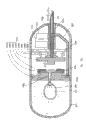
图1是示意地表示本发明的实施方式1的被检体内导入装置的一个构成例子的剖视示意图。该被检体内导入装置1可导入被检体的内部,用于向被检体内的目标部位注射预先储存在储存室内的药液。如图1所示,被检体内导入装置1具有患者等被检体易于吞服的尺寸的胶囊型壳体2。被检体内导入装置1在该壳体2的内部具有球囊4、注射针5、管10及管路形成部11;上述球囊4形成有用于储存药液的储存室3;上述注射针5用于向被检体内的目标部位注射药液;上述管10及管路形成部11形成有与储存室3相连通的第1管路和与注射针5侧相连通的第2管路。另外,被检体内导入装置1具有连通调整机构12、弹性膜6、控制电路13和电源部14;上述连通调整机构12用于调整该第1管路与第2管路的连通状态;上述弹性膜6利用药液的排出压力使注射针5突出至壳体2的外部;上述控制电路13用于控制连通调整机构12的驱动状态;上述电源部14用于向控制电路供给驱动电力。 FIG. 1 is a schematic cross-sectional view schematically showing an example of the configuration of an intra-subject introduction device according to Embodiment 1 of the present invention. The subject body introduction device 1 can be introduced into a subject, and is used for injecting a drug solution pre-stored in a storage chamber into a target site in the subject. As shown in FIG. 1 , an intra-subject introduction device 1 has a capsule-shaped casing 2 of a size that can be easily swallowed by a subject such as a patient. The device for introducing into the subject 1 has a balloon 4, an injection needle 5, a tube 10, and a pipeline forming part 11 inside the housing 2; the balloon 4 is formed with a storage chamber 3 for storing a medicinal solution; It is used to inject medicinal liquid to the target site in the subject; the tube 10 and the channel forming part 11 are formed with a first channel communicating with the storage chamber 3 and a second channel communicating with the injection needle 5 side. In addition, the device 1 introduced into the subject has a communication adjustment mechanism 12, an elastic membrane 6, a control circuit 13, and a power supply unit 14; the communication adjustment mechanism 12 is used to adjust the communication state between the first pipeline and the second pipeline; The diaphragm 6 protrudes the injection needle 5 out of the casing 2 by the discharge pressure of the drug solution; the control circuit 13 controls the driving state of the communication adjustment mechanism 12; the power supply unit 14 supplies driving power to the control circuit. the
储存室3用于预先储存要向被检体内的目标部位注射的药液。具体地讲,在本实施方式1中,储存室3形成于由球囊4的内表面和管路形成部11的表面所包覆的区域,并在该区域中储存药液。球囊4形成了储存室3外壁的大部分,可利用橡胶等弹性构件制成。球囊4通过被注入规定量的药液而扩张,并在维持着这样的扩张状态、也就是使储存室3膨胀的状态的同时,储存药液。另外,在由后述连通调整机构12的作用和弹性膜6的作用使储存室3与注射针5连通了的情况下,球囊4随着其收 缩作用而减少储存室3的容积,而对药液加压,并借助注射针5排出药液。即,球囊4起到为了排出药液而缩小储存室3的容积而对药液加压的药液加压部件的作用。 The storage chamber 3 is used to store in advance a medical solution to be injected into a target site in the subject. Specifically, in the first embodiment, the storage chamber 3 is formed in the area covered by the inner surface of the balloon 4 and the surface of the channel forming portion 11, and stores the medical solution in this area. The balloon 4 forms most of the outer wall of the storage chamber 3 and can be made of elastic members such as rubber. The balloon 4 is inflated by injecting a predetermined amount of the medical solution, and stores the medical solution while maintaining the expanded state, that is, the state in which the storage chamber 3 is inflated. In addition, when the storage chamber 3 and the injection needle 5 are communicated by the action of the communication adjustment mechanism 12 described later and the action of the elastic membrane 6, the volume of the storage chamber 3 is reduced by the balloon 4 along with its contraction action, and the volume of the storage chamber 3 is reduced. The medicinal liquid is pressurized, and the medicinal liquid is discharged by means of the injection needle 5 . That is, the balloon 4 functions as a liquid medicine pressurizing member that reduces the volume of the storage chamber 3 to pressurize the liquid medicine in order to discharge the liquid medicine. the
注射针5利用与排出药液相关的规定的驱动源自壳体2突出,用于向被检体内的目标部位注射储存在储存室3中的药液。注射针5在内部形成有管路5a,并设置成可相对于壳体2自由出入,该管路5a将用于穿刺入被检体内的前端侧(呈尖形的一侧)和基端侧附近的侧部相连通。具体地讲,在注射针5被弹性膜6保持的状态下,注射针5的基端侧被收容于针收容部7中,注射针5通过弹性膜6的扩张作用而突出至壳体2的外部,并通过弹性膜6的收缩作用被收容于壳体2内。在该情况下,注射针5沿设在壳体2上的引导机构2b滑动,而可以经由壳体2的开口部2a出入。 The injection needle 5 is protruded from the housing 2 by a predetermined drive related to the discharge of the drug solution, and is used to inject the drug solution stored in the storage chamber 3 into a target site in the subject. The injection needle 5 has a tube 5a formed inside, and is provided so as to be freely accessible relative to the housing 2, and the tube 5a will be used to puncture into the front end side (pointed side) and the base end side of the subject. The nearby sides are connected. Specifically, in a state where the injection needle 5 is held by the elastic membrane 6, the base end side of the injection needle 5 is accommodated in the needle housing portion 7, and the injection needle 5 protrudes to the bottom of the housing 2 by the expansion action of the elastic membrane 6. outside, and is accommodated in the housing 2 by the contraction of the elastic film 6 . In this case, the injection needle 5 can slide in and out through the opening 2 a of the case 2 by sliding along the guide mechanism 2 b provided in the case 2 . the
弹性膜6为橡胶或硅树脂等的弹性构件,其用途在于:利用药液的排出压力使注射针5突出,或利用弹力将突出的注射针5收容于壳体2内。具体地讲。弹性膜6以被注射针5贯穿的状态将注射针5保持在大致中央附近,其周缘被膜保持部8保持。在该情况下,弹性膜6的被注射针5和膜保持部8夹着的区域是自由的,可在该区域受到药液的排出压力(与排出药液相关的物理力的一个例子),因而该弹性膜6可扩张。 The elastic film 6 is an elastic member such as rubber or silicone resin, and is used to protrude the injection needle 5 by the discharge pressure of the drug solution, or accommodate the protruding injection needle 5 in the housing 2 by elastic force. Specifically. The elastic membrane 6 holds the injection needle 5 in the vicinity of the center while being penetrated by the injection needle 5 , and its peripheral edge is held by the membrane holding portion 8 . In this case, the region of the elastic membrane 6 sandwiched between the injection needle 5 and the membrane holding portion 8 is free, and the discharge pressure of the medical solution (an example of physical force related to the discharge of the medical solution) can be received in this region, The elastic membrane 6 is thus expandable. the
因具有这样的弹性膜6及球囊4、和后述管10及管路形成部11而得以实现的药液排出部件,缩小储存室3的容积而排出储存室3内的药液,并且利用与排出该药液相关的物理力(例如,药液的排出压力)使注射针5自壳体2突出。即,该药液排出部件起到排出储存室3内的药液、并产生用于使注射针5自壳体2突出的驱动力(与排出药液相关的物理力)的驱动源(与排出药液相关的驱动源)的作用。 The medical solution discharge member realized by having such an elastic membrane 6 and balloon 4, and the tube 10 and the channel forming part 11 described later reduces the volume of the storage chamber 3 to discharge the medical solution in the storage chamber 3, and utilizes The physical force (for example, the discharge pressure of the medical solution) associated with discharging the medical solution causes the injection needle 5 to protrude from the housing 2 . That is, the drug solution discharge member functions as a driving source (related to the discharge of the drug solution) that discharges the drug solution in the storage chamber 3 and generates a driving force (physical force related to discharging the drug solution) for causing the injection needle 5 to protrude from the housing 2 . The role of the driving source related to the liquid medicine). the
针收容部7用于收容注射针5的基端侧。另外,膜保持部8用于如上述那样地保持弹性膜6。具体地讲,膜保持部8设于壳体2的开口部2a附近的内壁上,保持用于保持注射针5的弹性膜6的周缘。针收容部7在将弹性膜6的周缘压靠在膜保持部8上的状态下固定设置于壳体2的内侧。在该情况下,在由弹性膜6和针收容部7所包围的区域形成了空间9,该空间9用于临时储存借助注射针5而要向外部排出的药液。 The needle accommodating portion 7 accommodates the base end side of the injection needle 5 . In addition, the film holding part 8 is used to hold the elastic film 6 as described above. Specifically, the membrane holding portion 8 is provided on the inner wall near the opening 2 a of the housing 2 and holds the peripheral edge of the elastic membrane 6 for holding the injection needle 5 . The needle accommodating portion 7 is fixedly provided inside the housing 2 in a state where the peripheral edge of the elastic membrane 6 is pressed against the membrane holding portion 8 . In this case, a space 9 is formed in a region surrounded by the elastic membrane 6 and the needle housing portion 7 , and the space 9 is used to temporarily store the medicinal solution to be discharged to the outside via the injection needle 5 . the
另外,在该状态下,由于针收容部7及膜保持部8固定弹性膜6的周缘部分,因此,弹性膜6可防止被排出到空间9中的药液漏出到除了注射针5及管10之外的例如配置有球囊4或膜保持部8等的壳体2内的区域。 In addition, in this state, since the peripheral portion of the elastic membrane 6 is fixed by the needle accommodating portion 7 and the membrane holding portion 8, the elastic membrane 6 can prevent the liquid medicine discharged into the space 9 from leaking to other than the injection needle 5 and the tube 10. Other than that, for example, the area inside the housing 2 where the balloon 4 or the membrane holding part 8 is arranged. the
管10及管路形成部11用于形成上述第1管路及第2管路。具体地讲,管路形成部11在内部形成有管路11a、11b,并在使管路11b与空间9相连通的状态下安装有管10。在该情况下,管路11a与球囊4的内部、即储存室3相连通,管路11b及管10与比储存室3靠近注射针5一侧的空间9相连通。即,管路11a形成上述第1管路,管路11b及管10形成上述第2管路。在通过连通调整机构12的作用使管路11a、11b相连通的情况下,这样的管10及管路形成部11使储存室3内的药液向空间9中流通。 The pipe 10 and the duct forming part 11 are used to form the first duct and the second duct described above. Specifically, the duct forming part 11 has the ducts 11 a and 11 b formed therein, and the pipe 10 is attached in a state where the duct 11 b communicates with the space 9 . In this case, the tube 11a communicates with the inside of the balloon 4 , that is, the storage chamber 3 , and the tube 11b and the tube 10 communicate with the space 9 closer to the injection needle 5 than the storage chamber 3 . That is, the pipeline 11a forms the above-mentioned first pipeline, and the pipeline 11b and the pipe 10 form the above-mentioned second pipeline. Such a tube 10 and a channel forming portion 11 allow the liquid medicine in the storage chamber 3 to flow into the space 9 when the tubes 11a and 11b are communicated by the action of the communication adjusting mechanism 12 . the
另外,期望使该管路11a、11b形成为沿壳体2的长度方向互相平行。通过这样形成管路11a、11b,可以将管路形成部11的规模限定得尽可能小,从而可以促进被检体内导入装置1的小型化。 In addition, it is desirable to form the ducts 11a and 11b so as to be parallel to each other along the longitudinal direction of the casing 2 . By forming the conduits 11a and 11b in this way, the scale of the conduit forming part 11 can be limited as small as possible, and the miniaturization of the device 1 introduced into the subject can be promoted. the
连通调整机构12用于基于控制电路13的控制来调整管路11a、11b的连通状态。连通调整机构12具有通过进行这种调整动作而控制排出动作的开始和停止的作用,该排出动作为使球囊4的收缩动作,即缩小储存室3的容积而对药液加压从而排出 药液。具体地讲,连通调整机构12包括片保持部12a、片构件12b和固定构件12c;上述片保持部12a贯穿有管路形成部11;上述片构件12b以覆盖自片保持部12a上露出的管路形成部11的端部的方式,配置于片保持部12a上;上述固定构件12c以使片构件12b的周缘部分紧贴在片保持部12a的状态下固定该片构件12b的周缘部分。另外,连通调整机构12还具有推压构件12d、弹簧12f、弹簧基板12g和形状记忆构件12e;上述推压构件12d对片构件12b施加规定的推压力;上述弹簧12f用于产生由推压构件12d所施加的推压力;上述弹簧基板12g用于保持弹簧12f;上述形状记忆构件12e用于使推压构件12d的位置相对于片构件12b产生变化。 The communication adjustment mechanism 12 is used to adjust the communication state of the pipelines 11 a and 11 b based on the control of the control circuit 13 . The connection adjustment mechanism 12 has the function of controlling the start and stop of the discharge action by performing such an adjustment action. The discharge action is the contraction action of the balloon 4, that is, the volume of the storage chamber 3 is reduced to pressurize the liquid medicine to discharge the medicine. liquid. Specifically, the communication adjustment mechanism 12 includes a sheet holding portion 12a, a sheet member 12b, and a fixing member 12c; the sheet holding portion 12a penetrates the pipeline forming portion 11; the sheet member 12b is used to cover the pipe exposed from the sheet holding portion 12a. The end portion of the passage forming portion 11 is disposed on the sheet holding portion 12a; the fixing member 12c fixes the peripheral portion of the sheet member 12b so that the peripheral portion of the sheet member 12b is in close contact with the sheet holding portion 12a. In addition, the communication adjustment mechanism 12 also has a pressing member 12d, a spring 12f, a spring base plate 12g, and a shape memory member 12e; the pressing member 12d applies a predetermined pressing force to the sheet member 12b; The pressing force applied by 12d; the spring base plate 12g is used to hold the spring 12f; the shape memory member 12e is used to change the position of the pressing member 12d relative to the sheet member 12b. the
]片保持部12a是用于保持片构件12b的板状构件。具体地讲,片保持部12a例如固定于壳体2的内壁上,被管路形成部11贯穿的状态保持管路形成部11,并在覆盖该管路形成部11的端部露出的区域的状态下保持片构件12b。另外,最好是在片保持部12a或弹簧基板12g上形成通气口(未图示),使得配置有球囊4的空间、配置有推压构件12d等的空间、和配置有控制电路13等的空间不相互切断。这种构造可以抑制在配置有球囊4的壳体2内的空间随着球囊4的收缩动作产生负压,而防止阻碍球囊4的伸缩动作。 ] The sheet holding portion 12a is a plate-shaped member for holding the sheet member 12b. Specifically, the piece holding portion 12a is fixed to the inner wall of the casing 2, holds the pipeline forming portion 11 in a state penetrated by the pipeline forming portion 11, and covers the exposed area of the end portion of the pipeline forming portion 11. The sheet member 12b is held in this state. In addition, it is preferable to form a vent (not shown) in the sheet holding portion 12a or the spring base plate 12g so that the space where the balloon 4 is arranged, the space where the pressing member 12d and the like are arranged, and the space where the control circuit 13 and the like are arranged. spaces are not cut off from each other. Such a structure can prevent negative pressure from being generated in the space inside the casing 2 where the balloon 4 is disposed along with the contraction operation of the balloon 4 , thereby preventing the expansion and contraction operation of the balloon 4 from being hindered.
片构件12b用于从物理上控制上述第1管路与第2管路的连通状态、即控制管路11a、11b的连通状态。具体地讲,片构件12b例如由硅胶片(siricon sheet)等水密且柔软的材料形成,并以覆盖露出于片保持部12a上的管路形成部11的端部的方式配置于片保持部12a上,并且,片构件12b的周缘部分被固定构件12c以紧贴在片保持部12a的状态固定。另外,片构件12b在被推压构件12d施加了规定的推压力时,维持在紧贴于管路形成部11的端部的状态,由此,封闭管路11a、11b的开口部,切断了管路11a、11b的连通状态。另一方面,片构件12b在由推压构件12d施加的推压力降低了时,因自管路11a排出的药液的排出压力而离开管路形成部11的端部,由此使管路11a、11b连通。 The sheet member 12b is used to physically control the communication state of the first pipeline and the second pipeline, that is, the communication state of the control pipelines 11a and 11b. Specifically, the sheet member 12b is formed of a watertight and flexible material such as a silicone sheet, and is disposed on the sheet holding portion 12a so as to cover the end of the duct forming portion 11 exposed on the sheet holding portion 12a. Furthermore, the peripheral portion of the sheet member 12b is fixed in a state of being in close contact with the sheet holding portion 12a by the fixing member 12c. In addition, when the sheet member 12b is given a predetermined pressing force by the pressing member 12d, it is maintained in a state of being in close contact with the end of the duct forming portion 11, thereby closing the openings of the ducts 11a, 11b and cutting off. The communication status of the pipelines 11a and 11b. On the other hand, when the pressing force applied by the pressing member 12d decreases, the sheet member 12b is separated from the end of the tube forming part 11 due to the discharge pressure of the liquid medicine discharged from the tube 11a, thereby making the tube 11a , 11b are connected. the
固定构件12c用于将片构件12b的周缘部分固定在片保持部12a上。具体地讲,固定构件12c对片构件12b的周缘部分朝片保持部12a侧施加推压力,从而将片构件12b的周缘部分和片保持部12a紧贴固定在一起。在该状态下,固定构件12c固定片构件12b,从而使片构件12b的中心部分、即管路形成部11的端部附近与推压构件12d的推压力相应地自由变形。与此同时,这样配置的片构件12b防止在管路11a、11b之间流通的药液漏出到除了管路11a、11b之外的例如配置有推压构件12d或控制电路13等的壳体2内的区域。 The fixing member 12c is used to fix the peripheral portion of the sheet member 12b to the sheet holding portion 12a. Specifically, the fixing member 12c applies a pressing force to the peripheral portion of the sheet member 12b toward the sheet holding portion 12a side, thereby closely fixing the peripheral portion of the sheet member 12b and the sheet holding portion 12a. In this state, the fixing member 12c fixes the sheet member 12b so that the center portion of the sheet member 12b, that is, the vicinity of the end of the duct forming portion 11 is freely deformable in accordance with the pressing force of the pressing member 12d. At the same time, the thus-arranged sheet member 12b prevents the liquid medicine circulating between the tubes 11a, 11b from leaking to the housing 2, in which the pressing member 12d or the control circuit 13, etc., for example, are arranged other than the tubes 11a, 11b. area within. the
弹簧12f用于产生由推压构件12d对片构件12b施加的推压力。具体地讲,弹簧12f的一端固定在弹簧基板12g上,且其另一端固定在推压构件12d上,并且,其弹簧长度被维持在比自然长度短的状态。这样配置的弹簧12f起到对推压构件12d朝向片构件12b所处位置的方向施加弹力(反弹力)的作用。 The spring 12f is used to generate an urging force applied to the sheet member 12b by the urging member 12d. Specifically, one end of the spring 12f is fixed to the spring base plate 12g, the other end is fixed to the pressing member 12d, and the spring length thereof is kept shorter than the natural length. The spring 12f thus arranged functions to apply an elastic force (repulsion force) to the pressing member 12d toward the position where the sheet member 12b is located. the
形状记忆构件12e用于使推压构件12d相对于片构件12b的位置产生变化。具体地讲,形状记忆构件12e具有棒状或螺旋状(例如,SMA线圈)的构造,其由具有规定的形状记忆特性、并具有规定的电阻值的形状记忆合金形成。该形状记忆构件12e的一端固定在弹簧基板12g上,且其另一端固定在推压构件12d上,例如具有在与被检体内部的温度相同的温度条件下足以使推压构件12d抵接在片构件12b上的长度。另一方面,形状记忆构件12e起到这样的作用:在与规定温度、例如被检体内 部的温度相比足够高的温度条件下,其形状产生变化,而使推压构件12d与片构件12b相分离。 The shape memory member 12e is used to change the position of the pressing member 12d relative to the sheet member 12b. Specifically, the shape-memory member 12e has a rod-like or helical (for example, SMA coil) configuration formed of a shape-memory alloy having a prescribed shape-memory characteristic and a prescribed resistance value. One end of the shape memory member 12e is fixed to the spring base plate 12g, and the other end is fixed to the pressing member 12d. The length on the sheet member 12b. On the other hand, the shape-memory member 12e functions to change its shape under a temperature condition sufficiently higher than a predetermined temperature, for example, the temperature inside the subject, so that the pressing member 12d and the sheet member 12b phase separation. the
控制电路13起到这样的作用:通过是否向形状记忆构件12e供给电流来控制形状记忆构件12e的形状变化,从而通过控制其形状变化来控制储存室3内的药液的排出开始及排出停止。具体地讲,控制电路13起到这样的作用:在已被导入到被检体内部的被检体内导入装置1到达了被检体内的目标部位、例如患部时,向形状记忆构件12e供给电流。该电流在形状记忆构件12e中流动,从而在形状记忆构件12e中产生焦耳热,而因该焦耳热使形状记忆构件12e上升至规定温度以上。由于该温度的上升,使形状记忆构件12e的形状如上述那样地产生变化。在该情况下,储存室3内的药液经由管路11a、11b、管10、空间9和注射针5的管路5a,而被排出(注射)到被检体内的目标部位。另一方面,控制电路13通过停止向形状记忆构件12e供给电流,从而使形状记忆构件12e的温度降低至小于规定温度(例如,与被检体内的温度相同的程度)。利用该温度的降低,使形状记忆构件12e的形状变化成将推压构件12d推压在片构件12b上。在该情况下,球囊4停止缩小储存室3容积的动作,而使药液的排出动作停止。 The control circuit 13 functions to control the shape change of the shape memory member 12e by whether or not to supply current to the shape memory member 12e, thereby controlling the discharge start and stop of the liquid medicine in the storage chamber 3 by controlling the shape change. Specifically, the control circuit 13 plays a role of supplying current to the shape memory member 12e when the intra-subject introduction device 1 introduced into the subject reaches a target site in the subject, such as an affected part. The current flows through the shape memory member 12e to generate Joule heat in the shape memory member 12e, and the shape memory member 12e rises to a predetermined temperature or higher due to the Joule heat. Due to this rise in temperature, the shape of the shape memory member 12e changes as described above. In this case, the medicinal solution in the storage chamber 3 is discharged (injected) to the target site in the subject via the conduits 11 a , 11 b , the tube 10 , the space 9 , and the conduit 5 a of the injection needle 5 . On the other hand, the control circuit 13 stops the current supply to the shape memory member 12e, thereby reducing the temperature of the shape memory member 12e to a temperature lower than a predetermined temperature (for example, about the same as the temperature in the subject). Utilizing this decrease in temperature, the shape of the shape-memory member 12e is changed to press the pressing member 12d against the sheet member 12b. In this case, the balloon 4 stops the operation of shrinking the volume of the storage chamber 3 and stops the discharge operation of the medicinal solution. the
另外,作为规定由控制电路13供给电流的时机的构造,例如,可以做成具有计时器(timer)机构的构造,也可以做成内置有无线电接收机、并从外部供给控制信号的构造。 In addition, as a structure for specifying the timing of supplying current from the control circuit 13, for example, a structure having a timer mechanism may be adopted, or a structure may be formed in which a radio receiver is built in and a control signal is supplied from the outside. the
接着,对被检体内导入装置1的动作进行说明。图2是示意地例示出对弹性膜6施加药液的排出压力而使注射针5自壳体2突出的状态的剖视示意图。下面,参照图2说明注射针5的突出动作及药液的排出动作。 Next, the operation of the device 1 introduced into the subject will be described. 2 is a schematic cross-sectional view schematically illustrating a state in which the injection needle 5 protrudes from the housing 2 by applying the discharge pressure of the drug solution to the elastic membrane 6 . Next, the protruding operation of the injection needle 5 and the discharge operation of the medicinal solution will be described with reference to FIG. 2 . the
首先,控制电路13对形状记忆构件12e供给规定的电流, 在形状记忆构件12e中产生焦耳热而使形状记忆构件12e的温度上升。形状记忆构件12e在温度上升至规定温度以上时,其形状产生变化。具体地讲,形状记忆构件12e形成为棒状,并预先进行形状记忆,以在高温时使其长度方向长度进行收缩,在其温度因焦耳热而上升至规定温度以上时,以其长度方向长度变短的方式产生变形。形状记忆构件12e的长度方向长度上述那样地进行收缩,从而如图2所示,被固定在形状记忆构件12e一端的推压构件12d向离开片构件12b的方向移动。由此,对片构件12b的推压力减小或消失(即为0)。 First, the control circuit 13 supplies a predetermined current to the shape-memory member 12e, and Joule heat is generated in the shape-memory member 12e to raise the temperature of the shape-memory member 12e. The shape memory member 12e changes its shape when the temperature rises above a predetermined temperature. Specifically, the shape-memory member 12e is formed in a rod shape, and the shape memory is performed in advance so that its length in the longitudinal direction shrinks at high temperature, and when its temperature rises above a predetermined temperature due to Joule heat, its length in the longitudinal direction shrinks. The short way creates deformation. As the longitudinal length of the shape memory member 12e shrinks as described above, the pressing member 12d fixed to one end of the shape memory member 12e moves away from the sheet member 12b as shown in FIG. 2 . Thus, the pressing force against the sheet member 12b decreases or disappears (that is, becomes 0). the
这样,对片构件12b的推压力减小,从而解除了片构件12b与管路形成部11端部的紧贴状态。在该情况下,管路11a、11b变化为连通状态,以次为契机,球囊4因其收缩作用而开始了缩小储存室3的容积的收缩动作,并对储存室3内的药液加压。如图2所示,因该球囊4的收缩动作而被加压了的药液经由形成上述第1管路及第2管路的管路11a、11b、和管10,被向注射针5侧、即空间9中排出。 In this way, the pressing force on the sheet member 12b is reduced, and the tight contact state between the sheet member 12b and the end portion of the duct forming portion 11 is released. In this case, the pipelines 11a and 11b are changed to the connected state. Taking this as an opportunity, the balloon 4 begins to contract to reduce the volume of the storage chamber 3 due to its contraction action, and the liquid medicine in the storage chamber 3 is added. pressure. As shown in FIG. 2 , the medical solution pressurized by the deflation operation of the balloon 4 is delivered to the injection needle 5 through the tubes 11a, 11b and the tube 10 forming the first and second tubes. side, that is, space 9 discharge. the
只要管路11a、11b是连通状态,该球囊4就继续进行收缩动作,而依次向空间9中排出药液,并且对弹性膜6施加药液的排出压力。在该情况下,空间9内的药液积存量随着该球囊4的收缩动作而增加,随着该积存量的增加,对弹性膜6施加的药液排出压力增加。利用这样地施加的药液排出压力使弹性膜6渐渐扩张,并随着该扩张使注射针5向自壳体2突出的方向滑动。与此同时,弹性膜6产生了使该扩张了的形状收缩(即,欲恢复为原来的形状)的弹力。通过施加该弹力以上的排出压力,使弹性膜6继续扩张。在该药液的排出压力增加到了规定的临界值以上时,弹性膜6使注射针5自壳体2突出,并使注射针5的管路5a与空间9相连通。 As long as the tubes 11 a and 11 b are in communication, the balloon 4 continues to deflate to sequentially discharge the drug solution into the space 9 and apply the discharge pressure of the drug solution to the elastic membrane 6 . In this case, the storage amount of the medical solution in the space 9 increases with the deflation operation of the balloon 4 , and the discharge pressure of the medical solution applied to the elastic membrane 6 increases as the storage amount increases. The elastic membrane 6 is gradually expanded by the drug solution discharge pressure applied in this way, and the injection needle 5 is slid in the direction protruding from the housing 2 along with the expansion. At the same time, the elastic membrane 6 generates an elastic force that shrinks the expanded shape (that is, returns to the original shape). The elastic membrane 6 continues to expand by applying a discharge pressure higher than the elastic force. When the discharge pressure of the liquid medicine increases above a predetermined critical value, the elastic membrane 6 protrudes the injection needle 5 from the housing 2 and communicates the tube 5 a of the injection needle 5 with the space 9 . the
弹性膜6上述那样地使注射针5突出,从而成为使管路11a、11b、管10、空间9和管路5a相互连通的状态,球囊4可以使药液经由管路11a、11b、管10、空间9和管路5a而从注射针5的前端排出。即,该球囊4、弹性膜6、管10及管路形成部11构成了这样一种药液排出部件:排出药液,并利用该药液的排出压力使注射针5自壳体2突出。另外,上述连通调整机构12及控制电路13构成了排出控制部件,该排出控制部件进行使由该药液排出部件进行的药液排出动作开始的控制。 The elastic membrane 6 protrudes the injection needle 5 as described above, thereby becoming a state in which the pipelines 11a, 11b, the tube 10, the space 9, and the pipeline 5a communicate with each other, and the balloon 4 can allow the liquid medicine to pass through the pipelines 11a, 11b, the tube 10, the space 9 and the pipeline 5a are discharged from the front end of the injection needle 5. That is, the balloon 4, the elastic membrane 6, the tube 10, and the channel forming portion 11 constitute a liquid medicine discharge member that discharges the liquid medicine and protrudes the injection needle 5 from the case 2 by the discharge pressure of the liquid medicine. . In addition, the communication adjusting mechanism 12 and the control circuit 13 constitute discharge control means for controlling the start of the liquid medicine discharge operation by the liquid medicine discharge means. the
之后,随着完成排出所期望量的药液,球囊4渐渐停止收缩动作,而使对弹性膜6施加的药液排出压力渐渐降低。然后,在该药液排出压力降低到了小于弹力时,该扩张了的弹性膜6因该弹力而收缩,并使注射针5向壳体2内滑动,在该药液的排出压力降低到了小于上述临界值时,连注射针5的尖形前端都被收容于壳体2内。与此同时,针收容部7收容注射针5的基端部附近,而切断空间9与管路5a的连通状态。即,该球囊4在完成了排出所期望量以上的药液时结束收缩动作;该弹性膜6在排出了所期望量以上的药液时,利用弹力将注射针5收容于壳体2内。 Thereafter, as the discharge of the desired amount of the drug solution is completed, the balloon 4 gradually stops contracting, and the discharge pressure of the drug solution applied to the elastic membrane 6 gradually decreases. Then, when the liquid medicine discharge pressure drops below the elastic force, the expanded elastic film 6 shrinks due to the elastic force, and the injection needle 5 slides into the casing 2, and when the liquid medicine discharge pressure drops below the above-mentioned When the critical value is reached, even the pointed front end of the injection needle 5 is accommodated in the casing 2 . At the same time, the needle accommodating portion 7 accommodates the vicinity of the base end of the injection needle 5, and blocks the communication state between the space 9 and the tube 5a. That is, the balloon 4 ends the deflation operation when more than a desired amount of medical solution is discharged; and the elastic membrane 6 accommodates the injection needle 5 in the housing 2 by elastic force when more than a desired amount of medical solution is discharged. . the
另一方面,构成该排出控制部件的连通调整机构12及控制电路13可以进行切断上述管路11a、11b的连通状态的动作,并可以进行使球囊4的收缩动作带来的药液排出动作停止的控制。具体地讲,控制电路13停止对形状记忆构件12e供给电流,而使形状记忆构件12e的温度降低至小于规定温度。通过该控制电路13的控制,使形状记忆构件12e恢复为可使推压构件12d被抵接在片构件12b上的形状。在该情况下,推压构件12d利用由弹簧12f产生的推压力,使片构件12b与管路形成部11的端部处于紧贴状态,而切断管路11a、11b的连通状态。 On the other hand, the communication adjustment mechanism 12 and the control circuit 13 constituting the discharge control means can perform the operation of cutting off the communication state of the above-mentioned pipelines 11a, 11b, and can perform the operation of discharging the drug solution by deflation of the balloon 4. stop control. Specifically, the control circuit 13 stops supplying electric current to the shape-memory member 12e, and lowers the temperature of the shape-memory member 12e below a predetermined temperature. Controlled by the control circuit 13, the shape-memory member 12e returns to a shape in which the pressing member 12d can be brought into contact with the sheet member 12b. In this case, the pressing member 12d puts the sheet member 12b in close contact with the end of the duct forming portion 11 by the pressing force of the spring 12f, and blocks the communicating state of the ducts 11a, 11b. the
通过上述那样地切断管路11a、11b的连通状态,使球囊4停止其收缩动作,中断药液的排出动作。在该情况下,球囊4具有若未完成排出所期望量以上的药液则可以再次开始其收缩动作的程度的弹力(收缩力)。随着该排出动作的中断,施加于弹性膜6上的药液排出压力降低至上述临界值以下。由此,与上述完成了排出所期望量以上的药液的情况大致相同,弹性膜6将注射针5收容于壳体2内。 By cutting off the communicating state of the conduits 11a and 11b as described above, the deflation operation of the balloon 4 is stopped, and the discharge operation of the medicinal solution is interrupted. In this case, the balloon 4 has an elastic force (contraction force) to such an extent that the contraction operation can be restarted if the discharge of the desired amount or more of the medicinal solution is not completed. As this discharge operation is stopped, the discharge pressure of the chemical solution applied to the elastic membrane 6 falls below the above-mentioned critical value. Thus, the elastic membrane 6 accommodates the injection needle 5 in the case 2 in substantially the same manner as the above-mentioned case where the discharge of the desired amount or more of the medicinal solution is completed. the
之后,若控制电路13像上述那样地再次开始对形状记忆构件12e供给电流,则管路11a、11b再次成为连通状态,球囊4开始其收缩动作,而再次开始药液的排出动作。这样,连通控制机构12及控制电路13反复进行停止药液排出动作的控制、和再次开始药液排出动作的控制,从而,球囊4间断地反复进行其收缩动作,直到完成排出所期望量以上的药液为止。即,该用球囊4、弹性膜6、管10、及管路形成部11构成的药液排出部件,可以间断地反复进行由上述药液的排出压力使注射针5突出的动作和排出药液的动作。 Thereafter, when the control circuit 13 resumes supplying electric current to the shape memory member 12e as described above, the conduits 11a and 11b become in the communication state again, the balloon 4 starts its contraction operation, and the drug solution discharge operation is resumed. In this way, the communication control mechanism 12 and the control circuit 13 repeatedly perform the control of stopping the liquid medicine discharge operation and the control of restarting the liquid medicine discharge operation, so that the balloon 4 intermittently repeats its contraction operation until the discharge of more than the desired amount is completed. of the liquid medicine. That is, the medical solution discharge member composed of the balloon 4, the elastic membrane 6, the tube 10, and the pipeline forming portion 11 can intermittently repeat the action of protruding the injection needle 5 and discharging the drug by the discharge pressure of the medical solution. liquid action. the
其次,具体说明利用药液的排出压力使注射针5突出,而完成到对被检体内的目标部位注射药液为止的、被检体内导入装置1的一连串动作。图3是示意地例示出施加于弹性膜6上的药液排出压力的变化的示意图。图4是示意地表示从开始药液的排出动作起至开始注射针5的突出动作为止的状态变化的剖视示意图。图5是示意地表示从开始注射针5的突出动作起至将药液注射到目标部位为止的状态变化的剖视示意图。图6是示意地表示从将药液注射到目标部位至将注射针5收容于壳体2内为止的状态变化的剖视示意图。下面,参照图3~6说明到完成对被检体内的目标部位注射药液为止的、被检体内导入装置1的一连串动作。 Next, a series of operations of the subject introduction device 1 for injecting the drug solution to a target site in the subject by protruding the injection needle 5 by the discharge pressure of the drug solution will be described in detail. FIG. 3 is a schematic diagram schematically illustrating changes in the discharge pressure of the chemical solution applied to the elastic membrane 6 . FIG. 4 is a schematic cross-sectional view schematically showing a state change from the start of the discharge operation of the drug solution to the start of the protrusion operation of the injection needle 5 . FIG. 5 is a schematic cross-sectional view schematically showing a state change from the start of the protruding operation of the injection needle 5 to the injection of the drug solution into the target site. FIG. 6 is a schematic cross-sectional view schematically showing a state transition from injecting the drug solution to the target site to housing the injection needle 5 in the housing 2 . Next, a series of operations of the subject introduction device 1 until the injection of the drug solution to the target site in the subject is completed will be described with reference to FIGS. 3 to 6 . the
在被检体内导入装置1被导入至被检体内部、并到达了被检体内的目标部位例如患部100时,控制电路13如上述那样对形状记忆构件12e供给规定的电流,控制形状记忆构件12e的形状变化。通过该控制电路13的控制,使推压构件12d离开片构件12b而解除片构件12b与管路形成部11端部的紧贴状态。随之,如上述那样,在球囊4开始缩小储存室3的容积的收缩动作的同时,使药液经由管路11a、11b、和管10排出到空间9。该球囊4依次向空间9内排出药液,并对弹性膜6施加药液排出压力。 When the device 1 introduced into the subject is introduced into the subject and reaches a target site in the subject such as the affected part 100, the control circuit 13 supplies a predetermined current to the shape memory member 12e as described above to control the shape memory member 12e. shape change. Under the control of the control circuit 13 , the pressing member 12 d is separated from the sheet member 12 b to release the close contact between the sheet member 12 b and the end of the duct forming portion 11 . Subsequently, as described above, the medical solution is discharged into the space 9 through the tubes 11 a , 11 b , and the tube 10 at the same time as the balloon 4 starts the deflation operation to reduce the volume of the storage chamber 3 . The balloon 4 sequentially discharges the liquid medicine into the space 9 , and applies liquid medicine discharge pressure to the elastic membrane 6 . the
在该情况下,如图4所示,被检体内导入装置1自开始球囊4的收缩动作之前的状态、即未向空间9中排出药液的状态(初始状态),向将药液排出到空间9内而开始了对弹性膜6施加药液排出压力的状态(局部注射准备状态)变化。在该局部注射准备状态下,弹性膜6利用该药液的排出压力进行扩张,并使注射针5滑动至即将自壳体2突出。在该即将突出的状态下,注射针5的基端部附近的开口位于针收容部7的内部,由此切断空间9与管路5a的连通状态。 In this case, as shown in FIG. 4 , the body-introducing device 1 in the subject moves from the state before starting the deflation operation of the balloon 4 , that is, the state (initial state) in which the drug solution is not discharged into the space 9 , to the point where the drug solution is discharged. Entering the space 9, the state (local injection preparation state) starts to apply the liquid medicine discharge pressure to the elastic membrane 6. In this local injection ready state, the elastic membrane 6 is expanded by the discharge pressure of the drug solution, and the injection needle 5 is slid until it protrudes from the housing 2 . In this protruding state, the opening near the proximal end of the injection needle 5 is located inside the needle housing 7, thereby cutting off the communication state between the space 9 and the conduit 5a. the
在此,如图3所示,随着进行球囊4的收缩动作所经过的时间t,施加于弹性膜6上的药液的排出压力P产生变化。例如,在上述局部注射准备状态下,排出压力P上升至规定的临界值Pth。另外,该临界值Pth是为了由弹性膜6使注射针5自壳体2突出所需要的排出压力。即,弹性膜6在被施加了大于等于该临界值Pth的排出压力P时,可以使注射针5自壳体2突出。 Here, as shown in FIG. 3 , the discharge pressure P of the medical solution applied to the elastic membrane 6 changes with the elapsed time t during the deflation operation of the balloon 4 . For example, in the local injection preparation state described above, the discharge pressure P rises to a predetermined threshold value P th . In addition, this critical value P th is the discharge pressure required for the elastic membrane 6 to protrude the injection needle 5 from the housing 2 . That is, the elastic membrane 6 can cause the injection needle 5 to protrude from the housing 2 when the discharge pressure P equal to or greater than the critical value Pth is applied.
之后,球囊4通过继续进行上述收缩动作而进一步将药液排出到空间9内,进一步增大排出压力P。弹性膜6在因该球囊4的收缩动作而被施加了大于等于该临界值Pth的排出压力P时,进一步扩张而使注射针5自壳体2突出,并且使空间9与管路5a 相连通。在该情况下,如图5所示,被检体内导入装置1自上述局部注射准备状态向使注射针5刺入患部100而对患部100注射药液的状态(局部注射状态)变化。具体地讲,在该局部注射状态下,注射针5因弹性膜6的扩张作用而在引导机构2b上滑动、并自壳体2突出,并刺入患部100。与此同时,球囊4继续进行其收缩动作,并经由管路5a对患部100注射药液。通过上述那样地继续进行收缩动作,球囊4对患部100注射所期望量的药液。在该局部注射状态下,如图3所示,排出压力P增加至对患部100注射所期望量的药液为止,并维持大于等于临界值Pth 的状态。 Thereafter, the balloon 4 further discharges the medical solution into the space 9 by continuing the contraction operation described above, and the discharge pressure P is further increased. When the elastic membrane 6 is applied with a discharge pressure P greater than or equal to the critical value Pth due to the contraction of the balloon 4, it further expands to make the injection needle 5 protrude from the housing 2, and the space 9 and the pipeline 5a connected. In this case, as shown in FIG. 5 , the subject introduction device 1 changes from the local injection preparation state to a state in which the injection needle 5 is inserted into the affected part 100 to inject the drug solution into the affected part 100 (local injection state). Specifically, in this partial injection state, the injection needle 5 slides on the guide mechanism 2 b due to the expansion of the elastic membrane 6 , protrudes from the housing 2 , and penetrates into the affected part 100 . At the same time, the balloon 4 continues its deflation operation, and injects the medical solution into the affected part 100 through the tube 5a. By continuing the deflation operation as described above, the balloon 4 injects a desired amount of the medical solution into the affected part 100 . In this local injection state, as shown in FIG. 3 , the discharge pressure P is increased until a desired amount of the drug solution is injected into the affected part 100 , and the state is maintained equal to or greater than the threshold value P th .
在对患部100注射了所期望量的药液时,球囊4随着继续进行其收缩动作而渐渐降低其弹力(即,收缩力)。如图3所示,以注射了所期望量的药液的时刻为界线,排出压力P渐渐降低至临界值Pth。球囊4完成排出大于等于所期望量的药液,并基本丧失其收缩力而渐渐停止药液的排出动作。 When a desired amount of medical solution is injected into the affected part 100, the balloon 4 gradually reduces its elastic force (ie, contraction force) as the contraction operation continues. As shown in FIG. 3 , the discharge pressure P gradually decreases to the critical value P th with the time when a desired amount of the medicinal solution is injected as a boundary. The balloon 4 completes the discharge of the expected amount of liquid medicine, and basically loses its contraction force to gradually stop the discharge of the liquid medicine.
随着该排出压力P的降低,为了使注射针5突出而扩张了的弹性膜6利用其弹力进行收缩,而使注射针5向被收容于壳体2内的方向滑动。之后,如图3所示,随着球囊4收缩力的降低,排出压力P降低至小于临界值Pth。在该情况下,如图6所示,被检体内导入装置1自上述局部注射状态向局部注射完成状态变化。在该局部注射完成状态下,弹性膜6具有大于排出压力P的弹力,利用该弹力将注射针5自患部100拔出,将注射针5向壳体2内收容,直至连注射针5的尖形前端都收容于壳体2内为止。上述那样被收容了的注射针5沿引导机构2b滑动,而使其基端部附近的开口进入针收容部7的内部。由此,空间9与管路5a的连通状态被切断,球囊4完成了药液的排出动作。这样,被检体内导入装置1实现了到对被检体内的目标部位注射药液 结束为止的一连串的动作。 As the discharge pressure P decreases, the elastic membrane 6 expanded to protrude the injection needle 5 contracts due to its elastic force, and the injection needle 5 slides in the direction of being accommodated in the housing 2 . Afterwards, as shown in FIG. 3 , as the contraction force of the balloon 4 decreases, the discharge pressure P decreases below the critical value P th . In this case, as shown in FIG. 6 , the device 1 introduced into the subject changes from the aforementioned local injection state to the local injection completion state. In the state where the local injection is completed, the elastic membrane 6 has an elastic force greater than the discharge pressure P, and the injection needle 5 is pulled out from the affected part 100 by using the elastic force, and the injection needle 5 is stored in the housing 2 until the tip of the injection needle 5 is connected. Shaped front ends are accommodated in the casing 2 so far. The injection needle 5 accommodated as above slides along the guide mechanism 2b, and the opening near the base end enters the inside of the needle accommodation part 7. As shown in FIG. As a result, the communication state between the space 9 and the pipeline 5a is cut off, and the balloon 4 completes the discharge operation of the medicinal solution. In this way, the body-introducing device 1 in the subject realizes a series of operations until the injection of the drug solution into the target site in the subject is completed.
如以上说明的那样,本发明的实施方式1是这样的构造:以贯穿伸缩自由的弹性膜的大致中央的状态设置注射针,利用该弹性膜的伸缩作用使注射针滑动,在对这样保持着注射针的弹性膜施加药液的排出压力时,该弹性膜利用该药液的排出压力进行扩张,并使注射针自壳体突出。因此,可以实现这样的被检体内导入装置:不需要为了进行该注射针的突出动作而消耗新的驱动电力,而可以省电地进行注射针的突出动作。 As described above, Embodiment 1 of the present invention is such a structure that the injection needle is installed in a state of penetrating through the substantially center of the flexible elastic film, and the injection needle is slid by the expansion and contraction of the elastic film, and is held in this way. When the discharge pressure of the medical solution is applied to the elastic membrane of the injection needle, the elastic membrane is expanded by the discharge pressure of the medical solution, and the injection needle protrudes from the case. Therefore, it is possible to realize a device introduced into the subject that can perform the protruding operation of the injection needle with power saving without consuming new drive power for the protruding operation of the injection needle. the
另外,上述那样保持着注射针的弹性膜为这样的构造:随着其扩张作用产生弹力(收缩力),在被施加的药液排出压力降低至小于该弹力时,利用该弹力将注射针收容于壳体内。因此,可以实现这样的被检体内导入装置:不需要为了进行该注射针的收容动作而消耗新的驱动电力,而可以省电地进行注射针的收容动作。 In addition, the elastic membrane that holds the injection needle as described above has a structure that generates elastic force (contraction force) as it expands, and when the applied drug solution discharge pressure drops below the elastic force, the injection needle is accommodated by the elastic force. in the shell. Therefore, it is possible to realize a device introduced into a subject that can perform the storing operation of the injection needle with power saving without consuming new drive power for carrying out the storing operation of the injection needle. the
并且,通过采用该构造可以简单地实现这样的被检体内导入装置:不需要设置用于进行注射针的突出动作的新驱动机构,可以使对被检体内的目标部位注射药液的驱动机构简化,缩小装置规模。 In addition, by adopting this structure, it is possible to easily realize a device for introducing into a subject that does not require a new drive mechanism for protruding the injection needle, and can simplify the drive mechanism for injecting a drug solution to a target site in the subject. , reducing the size of the device. the
另外,可以简单地实现这样的被检体内导入装置:不需要设置用于进行注射针的收容动作的新驱动机构,可以将用于收容完成对被检体内的目标部位注射药液之后的注射针的驱动机构简化,缩小装置规模。可以上述那样地将注射针收容在壳体内的被检体内导入装置,可以防止注射针损伤被检体内的其他部位。 In addition, it is possible to easily implement the device for introducing into the body of the subject: it is not necessary to provide a new drive mechanism for storing the injection needle, and it is possible to use the injection needle for storing the injection needle after the injection of the drug solution to the target site in the subject. The driving mechanism is simplified and the scale of the device is reduced. The subject introduction device capable of accommodating the injection needle in the housing as described above can prevent the injection needle from damaging other parts of the subject. the
并且,使用伸缩自由的球囊来形成药液的储存室,利用该球囊的收缩力缩小储存室的容积而对药液进行加压,利用该球囊的收缩作用进行药液的排出动作。因此,不需要为了进行药 液的排出动作而消耗新的驱动电力,可以促进本发明被检体内导入装置的省电化。 In addition, a storage chamber for the medical solution is formed using a stretchable balloon, the volume of the storage chamber is reduced by the contraction force of the balloon to pressurize the medical solution, and the discharge operation of the medical solution is performed by the contraction of the balloon. Therefore, there is no need to consume new drive power for the discharge operation of the drug solution, and the power saving of the device introduced into the subject of the present invention can be promoted. the
采用这种构造的被检体内导入装置,实现了装置规模的小型化,并且可以具有对被检体内的目标部位注射药液的局部注射功能,使注射针突出而对被检体内的目标部位注射药液,之后,可以更省电地进行到收容该注射针为止的局部注射动作。 The device introduced into the subject with such a structure realizes miniaturization of the device scale, and can have a local injection function for injecting the drug solution to the target part in the subject, and the injection needle is protruded to inject the target part in the subject. Afterwards, the local injection operation up to the storage of the injection needle can be performed with more power saving. the
实施方式1的变形例1Modification 1 of Embodiment 1
接着,说明本发明实施方式1的被检体内导入装置1的变形例1。上述实施方式1利用球囊的收缩作用进行药液的排出动作,而本实施方式1的变形例1具有用于缩小药液储存室的容积而对药液进行加压的活塞机构,通过驱动该活塞机构来进行药液的排出动作。 Next, Modification 1 of the device introduced into the subject 1 according to Embodiment 1 of the present invention will be described. The above-mentioned first embodiment utilizes the contraction action of the balloon to discharge the liquid medicine, but the first modification of the first embodiment has a piston mechanism for reducing the volume of the liquid medicine storage chamber to pressurize the liquid medicine. The piston mechanism is used to discharge the liquid medicine. the
图7是示意地表示本发明实施方式1的变形例1的被检体内导入装置的一个构成例子的剖视示意图。如图7所示,在该被检体内导入装置20中,替代上述实施方式1的被检体内导入装置1的球囊4而设有活塞21、弹簧22和弹簧基板23,替代管路形成部11而设有管路形成部24。其他构造与实施方式1相同,对相同构成部分标注相同的附图标记。 Fig. 7 is a schematic cross-sectional view schematically showing an example of the configuration of the device introduced into the subject according to Modification 1 of Embodiment 1 of the present invention. As shown in FIG. 7 , in this subject body introduction device 20 , a piston 21 , a spring 22 , and a spring base plate 23 are provided instead of the balloon 4 of the subject body introduction device 1 of the first embodiment described above, and instead of the channel forming portion 11 and a pipeline forming portion 24 is provided. The other structures are the same as those in Embodiment 1, and the same reference numerals are assigned to the same components. the
与上述实施方式1的储存室3相同,储存室25用于预先储存药液。具体地讲,储存室25形成于由片保持部12a、活塞21和壳体2的一部分(即,位于片保持部12a与活塞21之间的部分)所围成的区域。 Like the storage chamber 3 in the first embodiment described above, the storage chamber 25 is used to pre-store the medical solution. Specifically, the storage chamber 25 is formed in an area surrounded by the sheet holding portion 12a, the piston 21, and a part of the housing 2 (ie, a portion located between the sheet holding portion 12a and the piston 21). the
活塞21用于沿壳体2的内壁滑动而缩小储存室25的容积。具体地讲,在通过上述连通调整机构12的作用和弹性膜6的作用使储存室25与注射针5相连通时,活塞21利用由弹簧22产生的反弹力向缩小储存室25的容积的方向滑动,而对储存室25内的药液进行加压,并经由注射针5排出药液。即,活塞21起到 这样的药液加压部件的作用:为了排出药液,缩小储存室25容积而对药液进行加压。 The piston 21 is used to slide along the inner wall of the casing 2 to reduce the volume of the storage chamber 25 . Specifically, when the storage chamber 25 communicates with the injection needle 5 through the action of the above-mentioned communication adjustment mechanism 12 and the action of the elastic film 6, the piston 21 uses the rebound force generated by the spring 22 to reduce the volume of the storage chamber 25. slide to pressurize the liquid medicine in the storage chamber 25 and discharge the liquid medicine through the injection needle 5 . That is, the piston 21 functions as a liquid medicine pressurizing member that reduces the volume of the storage chamber 25 to pressurize the liquid medicine in order to discharge the liquid medicine. the
弹簧22用于产生驱动力,该驱动力用于使活塞21向缩小储存室25容积的方向滑动。具体地讲,弹簧22维持在这样的状态:其一端固定在弹簧基板23上,并且其另一端固定在活塞21上,且弹簧长度短于自然长度。这样配置的弹簧22起到对活塞21朝使储存室25容积缩小的方向施加弹力(反弹力)的作用。弹簧22产生该反弹力来作为活塞21的驱动力。 The spring 22 is used to generate a driving force, and the driving force is used to make the piston 21 slide in the direction of reducing the volume of the storage chamber 25 . Specifically, the spring 22 is maintained in a state in which one end thereof is fixed to the spring base plate 23 and the other end thereof is fixed to the piston 21, and the spring length is shorter than the natural length. The spring 22 arranged in this way acts to apply an elastic force (repulsion force) to the piston 21 in a direction to reduce the volume of the storage chamber 25 . The spring 22 generates this rebound force as the driving force of the piston 21 . the
用于上述那样地缩小储存室25容积的活塞21、用于产生活塞21的驱动力的弹簧22、用于保持弹簧22的弹簧基板23、和供活塞21进行滑动的壳体2的一部分(即,位于活塞21及片保持部12a之间的壳体2的一部分)构成活塞机构,该活塞机构用于缩小药液储存室的容积而对药液进行加压,从而进行药液的排出动作。在该情况下,该壳体2的一部分起到该活塞机构的缸体的作用。 The piston 21 for reducing the volume of the storage chamber 25 as described above, the spring 22 for generating the driving force of the piston 21, the spring base plate 23 for holding the spring 22, and a part of the housing 2 for the piston 21 to slide (i.e. , a part of the casing 2 located between the piston 21 and the sheet holding portion 12a) constitutes a piston mechanism for reducing the volume of the liquid medicine storage chamber to pressurize the liquid medicine, thereby performing the discharge action of the medicine liquid. In this case, a part of the housing 2 functions as a cylinder of the piston mechanism. the
在此,因具有这种结构的活塞机构及管10、和后述管路形成部24而得以实现的药液排出部件,缩小储存室25的容积而排出储存室25内的药液,并利用与该药液的排出相关的物理力(例如,药液的排出压力)使注射针5自壳体2突出。即,该药液排出部件起到产生用于排出储存室25内的药液、并使注射针5自壳体2突出的驱动力(与药液的排出相关的物理力)的驱动源(与药液的排出相关的驱动源)的作用。 Here, the liquid medicine discharge member realized by the piston mechanism having such a structure, the tube 10, and the pipeline forming part 24 described later reduces the volume of the storage chamber 25 to discharge the liquid medicine in the storage chamber 25, and utilizes The injection needle 5 protrudes from the housing 2 due to the physical force associated with the discharge of the medical solution (for example, the discharge pressure of the medical solution). That is, the drug solution discharge member functions as a drive source (related to the physical force related to the discharge of the drug solution) that generates a driving force (physical force related to the discharge of the drug solution) for discharging the drug solution in the storage chamber 25 and causing the injection needle 5 to protrude from the housing 2 . The role of the driving source related to the discharge of the drug solution). the
管路形成部24及上述的管10用于形成与储存室25相连通的第1管路、和与比储存室25更靠近注射针5的一侧的空间9相连通的第2管路。具体地讲,管路形成部24在内部形成有管路24a、24b,并以连通管路24b和空间9的状态安装有管10。在该情况下,管路24a形成了与储存室25相连通的第1管路,管路 24b及管10形成了与空间9相连通的第2管路。另外,如图7所示,以贯穿片保持部12a、活塞21和弹簧基板23的状态设置管路形成部24。在该情况下,与上述管路形成部11的情况相同,管路形成部24的一端(形成有管路24a的一侧)在片保持部12a上露出,可以通过连通调整机构12及控制电路13调整管路24a、24b的连通状态。 The channel forming part 24 and the above-mentioned tube 10 are used to form a first channel communicating with the storage chamber 25 and a second channel communicating with the space 9 on the side closer to the injection needle 5 than the storage chamber 25 . Specifically, the duct forming part 24 has the ducts 24 a and 24 b formed therein, and the pipe 10 is attached in a state in which the duct 24 b communicates with the space 9 . In this case, the pipeline 24a forms a first pipeline communicating with the storage chamber 25, and the pipeline 24b and the pipe 10 form a second pipeline communicating with the space 9. In addition, as shown in FIG. 7 , the duct forming portion 24 is provided in a state of penetrating the sheet holding portion 12 a, the piston 21 , and the spring base plate 23 . In this case, as in the case of the above-mentioned duct forming part 11, one end of the duct forming part 24 (the side on which the duct 24a is formed) is exposed on the sheet holding part 12a, and can be connected to the adjustment mechanism 12 and the control circuit. 13 Adjust the communication state of the pipelines 24a, 24b. the
采用这种构造的被检体内导入装置20可以具有与上述实施方式1的被检体内导入装置1相同的功能。例如,与上述被检体内导入装置1相同,被检体内导入装置20可以利用药液的排出压力使注射针5突出。该被检体内导入装置20可以具有与上述被检体内导入装置1相同的作用效果。 The body-introduction device 20 having such a configuration can have the same function as the body-introduction device 1 of the first embodiment described above. For example, similarly to the above-described body-introduction device 1 , the body-introduction device 20 can protrude the injection needle 5 using the discharge pressure of the drug solution. The device 20 introduced into the subject can have the same function and effect as the device 1 introduced into the subject described above. the
实施方式1的变形例2Modification 2 of Embodiment 1
接着,说明本发明实施方式1的被检体内导入装置1的变形例2。上述实施方式1是通过连通调整机构12的作用来开始或停止药液的排出动作,而本实施方式1的变形例2具有通过控制电路13的控制来缩小药液储存室的容积而对药液进行加压的活塞机构,从而通过该活塞机构的驱动来进行药液的排出动作。 Next, Modification 2 of the device for introducing into a subject 1 according to Embodiment 1 of the present invention will be described. The above-mentioned first embodiment is to start or stop the discharge operation of the liquid medicine through the action of the communication adjustment mechanism 12, but the modification example 2 of the first embodiment has the ability to reduce the volume of the liquid medicine storage chamber under the control of the control circuit 13 to control the liquid medicine. A pressurized piston mechanism is used to discharge the liquid medicine by driving the piston mechanism. the
图8是示意地表示本发明实施方式1的变形例2的被检体内导入装置的一个构成例子的剖视示意图。如图8所示,在该被检体内导入装置30中,替代上述实施方式1的变形例1的被检体内导入装置20的连通调整机构12,而设有用于控制活塞21的滑动开始或滑动停止的形状记忆构件31a、31b。另外,被检体内导入装置30,为了保持该形状记忆构件31a、31b及弹簧22的各一端而设有弹簧基板23,为了以保持该形状记忆构件31a、31b及弹簧22的各另一端而设有活塞21。另外,被检体内导入装置30不具有上述管路形成部11。其他构造与实施方式1的变形例1相同,对相同构成部分标注相同的附图标记。 Fig. 8 is a schematic cross-sectional view schematically showing an example of the configuration of an intra-subject introduction device according to Modification 2 of Embodiment 1 of the present invention. As shown in FIG. 8 , in this subject body introduction device 30 , instead of the communication adjustment mechanism 12 of the subject body introduction device 20 according to Modification 1 of Embodiment 1 described above, there is provided a mechanism for controlling the start of sliding or sliding of the piston 21 . Stopped shape memory members 31a, 31b. In addition, the device 30 introduced into the subject is provided with a spring base plate 23 for holding the shape memory members 31a, 31b and one end of the spring 22, and for holding the other ends of the shape memory members 31a, 31b and the spring 22. There are pistons 21 . In addition, the intra-subject introduction device 30 does not have the above-mentioned channel forming portion 11 . The other structures are the same as those of Modification 1 of Embodiment 1, and the same reference numerals are assigned to the same components. the
与上述实施方式1的储存室3相同,储存室33用于预先储存药液。具体地讲,储存室33形成于由活塞21、管保持部32和壳体2的一部分(即,位于活塞21与管保持部32之间的部分)所围成的区域。 Like the storage chamber 3 in the first embodiment described above, the storage chamber 33 is used to pre-store the medical solution. Specifically, the storage chamber 33 is formed in an area surrounded by the piston 21 , the tube holding portion 32 , and a part of the housing 2 (ie, a portion located between the piston 21 and the tube holding portion 32 ). the
设于该被检体内导入装置30中的活塞21沿壳体2的内壁滑动而缩小储存室33的容积。具体地讲,在通过形状记忆构件31a的作用和弹性膜6的作用使储存室33与注射针5相连通时,活塞21利用由弹簧22产生的反弹力向缩小储存室33容积的方向滑动,而对储存室33内的药液进行加压,经由注射针5排出药液。 The piston 21 provided in the subject introduction device 30 slides along the inner wall of the casing 2 to reduce the volume of the storage chamber 33 . Specifically, when the storage chamber 33 communicates with the injection needle 5 through the action of the shape memory member 31a and the action of the elastic membrane 6, the piston 21 slides in the direction of reducing the volume of the storage chamber 33 by utilizing the rebound force generated by the spring 22, On the other hand, the liquid medicine in the storage chamber 33 is pressurized, and the liquid medicine is discharged through the injection needle 5 . the
设于该被检体内导入装置30中的弹簧22用于产生驱动力(反弹力),该驱动力用于使活塞21向缩小储存室33容积的方向滑动。形状记忆构件31a、31b用于控制活塞21向储存室33的滑动的开始或停止。该弹簧22及形状记忆构件31a、31b的各一端固定在弹簧基板23上,且它们的另一端分别固定在活塞21上。在该情况下,弹簧22维持在其弹簧长度短于自然长度的状态,并起到对活塞21朝使储存室33容积缩小的方向施加弹力(反弹力)的作用。 The spring 22 provided in the subject introduction device 30 is used to generate a driving force (repulsion force), and the driving force is used to slide the piston 21 in the direction of reducing the volume of the storage chamber 33 . The shape memory members 31a, 31b are used to control the start or stop of sliding of the piston 21 to the storage chamber 33 . One end of each of the spring 22 and the shape memory members 31 a and 31 b is fixed to the spring base plate 23 , and the other ends thereof are respectively fixed to the piston 21 . In this case, the spring 22 maintains a state in which the spring length is shorter than the natural length, and acts to apply elastic force (repulsion force) to the piston 21 in the direction of reducing the volume of the storage chamber 33 . the
另外,形状记忆构件31a、31b具有棒状或螺旋状(例如,SMA线圈)的构造,由具有规定的形状记忆特性、并具有规定的电阻值的形状记忆合金形成。在该情况下,例如在温度与被检体内部的温度相同的条件下,形状记忆构件31a、31b具有可抵消由弹簧22产生的反弹力的长度,起到使活塞21的滑动停止的作用。另一方面,在温度与规定的温度例如被检体内部温度相比足够高的条件下,形状记忆构件31a、31b变化为具有可充分对活塞21施加由弹簧22产生的反弹力的长度的形状,起到使活塞21开始向储存室33滑动的作用。 In addition, the shape memory members 31a and 31b have a rod-like or helical (for example, SMA coil) structure, and are formed of a shape-memory alloy having a predetermined shape-memory characteristic and a predetermined resistance value. In this case, for example, the shape memory members 31a and 31b have a length capable of canceling the rebound force of the spring 22 and function to stop the sliding of the piston 21 under the condition that the temperature is the same as that of the inside of the object. On the other hand, under the condition that the temperature is sufficiently higher than a predetermined temperature, for example, the internal temperature of the subject, the shape memory members 31a, 31b change to a shape having a length sufficient to apply the rebound force generated by the spring 22 to the piston 21. , to make the piston 21 start to slide towards the storage chamber 33 . the
如图8所示,管保持部32以与活塞21相面对的状态固定设 置在壳体2内壁中的、例如针收容部7的附近,在其开口部中贯穿并保持有管10。这样保持在管保持部32上的管10将储存室33与空间9连通起来。 As shown in FIG. 8 , the tube holding portion 32 is fixedly disposed on the inner wall of the housing 2, for example, near the needle receiving portion 7, in a state facing the piston 21, and the tube 10 is penetrated and held in the opening thereof. The tube 10 thus held on the tube holder 32 communicates the storage chamber 33 with the space 9 . the
在此,可以使用上述活塞21、弹簧22、形状记忆构件31a、31b、管保持部32、和壳体2的一部分来实现被检体内导入装置30的活塞机构。因具有这样的活塞机构和管10而得以实现的药液排出部件,缩小储存室33的容积而排出储存室33内的药液,并利用与该药液的排出相关的物理力(例如,药液的排出压力)使注射针5自壳体2突出。即,该药液排出部件起到产生用于排出储存室33内的药液、并使注射针5自壳体2突出的驱动力(与药液的排出相关的物理力)的驱动源(与药液的排出相关的驱动源)的作用。 Here, the piston mechanism of the intra-subject introduction device 30 can be realized by using the above-mentioned piston 21 , spring 22 , shape memory members 31 a , 31 b , tube holder 32 , and part of the housing 2 . The liquid medicine discharge member realized by having such a piston mechanism and the tube 10 reduces the volume of the storage chamber 33 to discharge the liquid medicine in the storage chamber 33, and utilizes the physical force related to the discharge of the liquid medicine (for example, medicine The discharge pressure of the liquid) causes the injection needle 5 to protrude from the housing 2. That is, the drug solution discharge member functions as a drive source (related to the physical force related to the discharge of the drug solution) that generates the driving force (physical force related to the discharge of the drug solution) for discharging the drug solution in the storage chamber 33 and causing the injection needle 5 to protrude from the housing 2 . The role of the driving source related to the discharge of the drug solution). the
设于该被检体内导入装置30中的控制电路13,通过向形状记忆构件31a、31b中供给规定的电流而产生焦耳热,从而使形状记忆构件31a、31b的温度上升至规定温度以上。由此,控制电路13进行控制,使得形状记忆构件31a、31b如上述那样地变形而使活塞21开始滑动。通过该滑动开始的控制,控制电路13可以开始由活塞21进行的药液的排出动作。另一方面,控制电路13通过停止向形状记忆构件31a、31b供给电流,使形状记忆构件31a、31b的温度降低至小于规定温度。由此,控制电路13进行控制,使得形状记忆构件31a、31b恢复形状而使活塞21停止滑动。通过该滑动停止的控制,控制电路13可以停止(中断)由活塞21进行的药液的排出动作。 The control circuit 13 provided in the body-introducing device 30 generates Joule heat by supplying a predetermined current to the shape-memory members 31a, 31b, thereby raising the temperature of the shape-memory members 31a, 31b to a predetermined temperature or higher. Thereby, the control circuit 13 performs control so that the shape-memory members 31a and 31b deform as described above, and the piston 21 starts to slide. By controlling the slide start, the control circuit 13 can start the discharge operation of the medicinal solution by the piston 21 . On the other hand, the control circuit 13 lowers the temperature of the shape-memory members 31a and 31b below a predetermined temperature by stopping the supply of electric current to the shape-memory members 31a and 31b. Thus, the control circuit 13 performs control so that the shape-memory members 31a and 31b return to their shapes to stop the sliding of the piston 21 . Through this slide stop control, the control circuit 13 can stop (interrupt) the discharge operation of the medicinal solution by the piston 21 . the
采用这种构造的被检体内导入装置30,可以具有与上述实施方式1的被检体内导入装置1相同的功能。另外,被检体内导入装置30不使用上述管路形成部11及连通调整机构12就可以控制药液排出动作的开始及停止,从而可以使该药液的排出动 作机构(具体地讲,是活塞机构)及其控制机构简化。因此,被检体内导入装置30可以具有与上述被检体内导入装置1相同的作用效果,并起到可以进一步促进装置规模小型化这样的效果。 The body-introduction device 30 having such a structure can have the same function as the body-introduction device 1 of the first embodiment described above. In addition, the introduction device 30 in the subject can control the start and stop of the liquid medicine discharge operation without using the above-mentioned pipeline forming part 11 and the communication adjustment mechanism 12, so that the liquid medicine discharge operation mechanism (specifically, Piston mechanism) and its control mechanism are simplified. Therefore, the device 30 introduced into the subject can have the same function and effect as that of the device 1 introduced into the subject described above, and can further promote the miniaturization of the device. the
实施方式2Embodiment 2
接着,说明本发明的实施方式2。上述实施方式1是对保持着注射针5的弹性膜6施加药液的排出压力而使注射针5突出,而本实施方式2为这样的构造:在缸体状的引导机构内设有注射针,对该注射针的后端部施加药液的排出压力,而推出注射针。 Next, Embodiment 2 of the present invention will be described. In the above-mentioned first embodiment, the discharge pressure of the drug solution is applied to the elastic membrane 6 holding the injection needle 5 to cause the injection needle 5 to protrude. However, the second embodiment has a structure in which the injection needle 5 is provided in a cylinder-shaped guide mechanism. , the discharge pressure of the liquid medicine is applied to the rear end of the injection needle, and the injection needle is pushed out. the
图9是示意地表示本发明实施方式2的被检体内导入装置的一个构成例子的剖视示意图。如图9所示,在该被检体内导入装置40中,替代上述实施方式1的被检体内导入装置1的引导机构2b而设有缸体状引导机构42,在引导机构42的内部替代注射针5而设有注射针41。另外,在注射针41中替代弹性膜6而设有弹簧43。另一方面,被检体内导入装置40未设置上述的针收容部7及膜保持部8而设有管10,以使管路11b与引导机构42的后端侧相连通。其他构造与实施方式1相同,对相同构成部分标注相同的附图标记。 FIG. 9 is a schematic cross-sectional view schematically showing an example of the configuration of the device introduced into the subject according to Embodiment 2 of the present invention. As shown in FIG. 9 , in this subject introduction device 40 , a cylinder-shaped guide mechanism 42 is provided instead of the guide mechanism 2 b of the subject introduction device 1 according to Embodiment 1, and inside the guide mechanism 42 instead of injection The needle 5 is provided with an injection needle 41 . In addition, a spring 43 is provided in the injection needle 41 instead of the elastic membrane 6 . On the other hand, the intra-subject introduction device 40 is provided with a tube 10 so that the tube 11 b communicates with the rear end side of the guide mechanism 42 instead of the above-mentioned needle housing portion 7 and membrane holding portion 8 . The other structures are the same as those in Embodiment 1, and the same reference numerals are assigned to the same components. the
注射针41利用与药液的排出相关的规定的驱动源自壳体2突出,与上述注射针5相同地用于对被检体内的目标部位注射药液。具体地讲,注射针41在内部形成有用于将刺入被检体中的前端侧和后端侧连通起来的管路41a,并在其后端侧形成有凸缘状的基端部41b。该注射针41可自由滑动地配置在缸体状引导机构42的内部空间中。在该情况下,如图9所示,基端部41b与引导机构42的内壁互相配合,基端部41b在引导机构42的内壁上滑动。即,该基端部41b起到在缸体状引导机构42的 内壁上滑动的活塞的作用。形成有这样的基端部41b的注射针41,在对其后端面施加了药液的排出压力时,利用该药液的排出压力沿引导机构42滑动而突出,并经由管路41a从前端排出药液。 The injection needle 41 protrudes from the casing 2 with a predetermined driving source related to the discharge of the drug solution, and is used to inject the drug solution to a target site in the subject similarly to the above-mentioned injection needle 5 . Specifically, the injection needle 41 is internally formed with a tube 41a for connecting the front end side and the rear end side of the punctured object, and has a flange-shaped base end portion 41b formed on the rear end side thereof. The injection needle 41 is slidably arranged in the inner space of the cylinder-shaped guide mechanism 42 . In this case, as shown in FIG. 9 , the base end portion 41 b cooperates with the inner wall of the guide mechanism 42 , and the base end portion 41 b slides on the inner wall of the guide mechanism 42 . That is, the base end portion 41b functions as a piston that slides on the inner wall of the cylinder-shaped guide mechanism 42. The injection needle 41 having such a base end portion 41b is, when the discharge pressure of the liquid medicine is applied to the rear end surface, the liquid medicine slides along the guide mechanism 42 to protrude due to the pressure of the liquid medicine discharge, and is discharged from the front end through the pipe line 41a. liquid medicine. the
引导机构42用于限制注射针41的滑动方向,并利用药液的排出压力使注射针41自壳体突出。具体地讲,如上述那样,引导机构42具有缸体状的构造,设于壳体2的规定位置、例如前端附近。另外,引导机构42在其前端侧(注射针的出入口侧)设有框形的弹簧基板42a,在其后端侧借助O型密封圈44安装有管10,该弹簧基板42a形成有可供注射针41穿过的开口。该引导机构42可以利用该O型密封圈44确保相对于壳体2内部水密。 The guide mechanism 42 is used to limit the sliding direction of the injection needle 41 and to make the injection needle 41 protrude from the case by the discharge pressure of the medical solution. Specifically, as described above, the guide mechanism 42 has a cylinder-shaped structure, and is provided at a predetermined position of the housing 2 , for example, near the front end. In addition, the guide mechanism 42 is provided with a frame-shaped spring base plate 42a on its front end side (injection needle inlet and outlet side), and the tube 10 is installed on its rear end side through an O-ring 44. The opening through which the needle 41 passes. The guide mechanism 42 can utilize the O-ring 44 to ensure watertightness relative to the inside of the casing 2 . the
另外,在引导机构42中的、注射针41的基端部41b与弹簧基板42a之间的区域配置有弹簧43。弹簧43用于将从壳体2突出的注射针41收纳在壳体2内。具体地讲,弹簧43以这样的方式配置:其一端固定在弹簧基板42a上,且其另一端固定在基端部41b上,在已将注射针41收容于壳体2内时,弹簧长度为自然长度。该弹簧43使注射针41向突出的方向滑动,并产生欲使注射针41返回到壳体2内的弹力(反弹力)。 In addition, a spring 43 is arranged in a region of the guide mechanism 42 between the base end portion 41b of the injection needle 41 and the spring base plate 42a. The spring 43 accommodates the injection needle 41 protruding from the case 2 in the case 2 . Specifically, the spring 43 is arranged in such a manner that one end thereof is fixed to the spring base plate 42a and the other end thereof is fixed to the base end portion 41b, and when the injection needle 41 is accommodated in the case 2, the spring length is natural length. The spring 43 slides the injection needle 41 in a protruding direction, and generates an elastic force (repulsion force) to return the injection needle 41 to the housing 2 . the
因具有这样的引导机构42、球囊4、管10和管路形成部11而得以实现的药液排出部件,缩小储存室3的容积而排出储存室3内的药液,并利用与该药液的排出相关的物理力(例如,药液的排出压力)使注射针41自壳体2突出。即,该药液排出部件起到产生用于排出储存室3内的药液、并使注射针41自壳体2突出的驱动力(与药液的排出相关的物理力)的驱动源(与药液的排出相关的驱动源)的作用。 The medicinal solution discharge member realized by having such a guide mechanism 42, balloon 4, tube 10, and pipeline forming part 11 reduces the volume of the storage chamber 3 to discharge the medicinal solution in the storage chamber 3, and utilizes the medicinal solution that is compatible with the medicinal solution. The injection needle 41 protrudes from the housing 2 by a physical force related to the discharge of the liquid (for example, the discharge pressure of the medical liquid). That is, the drug solution discharge member functions as a drive source (related to the physical force related to the discharge of the drug solution) that generates a driving force (physical force related to the discharge of the drug solution) for discharging the drug solution in the storage chamber 3 and causing the injection needle 41 to protrude from the housing 2 . The role of the driving source related to the discharge of the drug solution). the
接着,对被检体内导入装置40的动作进行说明。图10是示意地例示出对注射针41的后端面施加药液的排出压力而使注 射针41自壳体2突出的状态的剖视示意图。下面,参照图10说明注射针41的突出动作及药液的排出动作。 Next, the operation of the device 40 introduced into the subject will be described. 10 is a schematic cross-sectional view schematically illustrating a state in which the injection needle 41 protrudes from the housing 2 by applying the discharge pressure of the drug solution to the rear end surface of the injection needle 41. Next, the protruding operation of the injection needle 41 and the discharge operation of the medicinal solution will be described with reference to FIG. 10 . the
首先,如上述那样,控制电路13对连通调整机构12进行驱动控制,解除片构件12b与管路形成部11的端部的紧贴状态。通过该连通调整机构12的作用使管路11a、11b成为连通状态,如上述那样,球囊4开始收缩动作而进行药液的排出动作。在该情况下,储存室3内的药液经由管路11a、11b和管10而被排出至引导机构42的内部、具体是注射针41的后端面,再经由管路41a被从注射针41的前端排出。 First, as described above, the control circuit 13 controls the drive of the communication adjustment mechanism 12 to release the close contact between the sheet member 12 b and the end of the duct forming portion 11 . The conduits 11 a and 11 b are brought into a communication state by the action of the communication adjustment mechanism 12 , and the balloon 4 starts to deflate as described above to perform the discharge operation of the medicinal solution. In this case, the medicinal solution in the storage chamber 3 is discharged to the inside of the guide mechanism 42, specifically, the rear end surface of the injection needle 41 through the pipelines 11a, 11b and the tube 10, and then discharged from the injection needle 41 through the pipeline 41a. front end discharge. the
在此,球囊4通过上述那样地向引导机构42的内部排出药液,而对注射针41的后端面施加药液的排出压力,与此同时,经由管路41a将药液自注射针41的前端排出。随着球囊4继续其收缩动作,该药液的排出压力与例如图3所例示出的情况大致相同地进行变化(增加或减少)。在该药液的排出压力大于等于上述弹簧43的弹力时,注射针41的后端面被该药液的排出压力推压,并且注射针41在引导机构42中滑动而自壳体2突出。这样利用药液的排出压力使注射针41突出并排出药液,从而,被检体内导入装置40可以使注射针41穿刺入被检体内的目标部位而对该目标部位注射药液。 Here, the balloon 4 discharges the drug solution into the guide mechanism 42 as described above, and applies the discharge pressure of the drug solution to the rear end surface of the injection needle 41. front end discharge. As the balloon 4 continues its deflation operation, the discharge pressure of the medical solution changes (increases or decreases) substantially in the same manner as, for example, the case illustrated in FIG. 3 . When the discharge pressure of the medical solution is equal to or higher than the elastic force of the spring 43 , the rear end surface of the injection needle 41 is pushed by the discharge pressure of the medical solution, and the injection needle 41 slides in the guide mechanism 42 to protrude from the housing 2 . In this way, the injection needle 41 is protruded by the discharge pressure of the drug solution to discharge the drug solution, so that the intra-subject introducing device 40 can puncture the injection needle 41 into a target site in the subject and inject the drug solution to the target site. the
另一方面,如上述那样,球囊4完成排出所期望量以上的药液、并停止其收缩动作,另外,切断管路11a、11b的连通状态并停止收缩动作,而使施加于注射针41后端面的药液排出压力渐渐降低。在此,弹簧43随着上述注射针41的突出动作而产生弹力。在该药液的排出压力降低到了小于弹力时,该弹簧43通过该弹力使注射针41向壳体2内滑动,将例如已穿刺到被检体内目标部位的注射针41收容于壳体2内。 On the other hand, as described above, the balloon 4 completes discharging more than the desired amount of liquid medicine and stops its contraction action, and also cuts off the communication state of the pipelines 11a and 11b and stops the contraction action, so that the drug solution applied to the injection needle 41 The liquid medicine discharge pressure on the rear end surface gradually decreases. Here, the spring 43 generates elastic force in accordance with the protruding movement of the injection needle 41 described above. When the discharge pressure of the liquid medicine drops below the elastic force, the spring 43 slides the injection needle 41 into the casing 2 by the elastic force, and accommodates the injection needle 41 that has punctured the target site in the subject, for example, in the casing 2. . the
采用这种构造的被检体内导入装置40,可以具有与上述实 施方式1的被检体内导入装置1大致相同的功能,例如可以利用药液的排出压力使注射针41突出,另外,可以利用弹簧43的弹力将注射针41收容于壳体2内。并且,被检体内导入装置40将已排出到缸体状引导机构42内的药液排出压力施加于注射针41后端面,使注射针41突出,利用配置于该引导机构42内部的弹簧43的弹力将注射针41收容于壳体2内,因此不需要在壳体2内形成用于供上述弹性膜6扩张的空间。因此,可以进一步谋求壳体2内部的省空间化,从而,被检体内导入装置40可以具有与上述被检体内导入装置1相同的作用效果,并取得可以进一步促进装置规模小型化这样的效果。 The body-introduction device 40 with such a structure can have substantially the same functions as the body-introduction device 1 of the above-mentioned first embodiment. The elastic force of the spring 43 accommodates the injection needle 41 in the housing 2 . Furthermore, the device 40 for introducing into the subject applies the discharge pressure of the liquid medicine discharged into the cylinder-shaped guide mechanism 42 to the rear end surface of the injection needle 41, so that the injection needle 41 protrudes, and the force of the spring 43 disposed inside the guide mechanism 42 is used. Since the injection needle 41 is housed in the housing 2 by elastic force, it is not necessary to form a space in the housing 2 for the elastic membrane 6 to expand. Therefore, the interior space of the housing 2 can be further reduced, and therefore, the intra-subject introduction device 40 can have the same function and effect as the above-described subject introduction device 1 , and can further promote the effect of further reducing the size of the device. the
实施方式2的变形例1Modification 1 of Embodiment 2
接着,说明本发明实施方式2的被检体内导入装置40的变形例1。上述实施方式2为使注射针41在缸体状引导机构42的内部滑动的构造,而本实施方式2的变形例1为这样的构造:在注射针41的后端设有可自由伸缩的波纹管,与注射针41的突出或收容相对应地使该波纹管伸长或收缩。 Next, Modification 1 of the subject-introduction device 40 according to Embodiment 2 of the present invention will be described. The above-mentioned second embodiment has a structure in which the injection needle 41 slides inside the cylinder-shaped guide mechanism 42 , but the modification example 1 of the second embodiment has a structure in which a freely expandable bellows is provided at the rear end of the injection needle 41 . The corrugated tube is expanded or contracted in accordance with the protrusion or accommodation of the injection needle 41 . the
图11是示意地表示本发明的实施方式2的变形例1的被检体内导入装置的一个构成例子的剖视示意图。如图11所示,在该被检体内导入装置50中,替代上述实施方式2的被检体内导入装置40的引导机构42而设有引导机构52。另外,在被检体内导入装置50的注射针41的基端部41b设有使管10和管路41a相连通的波纹管51。其他构造与实施方式2相同,对相同构成部分标注相同的附图标记。 FIG. 11 is a schematic cross-sectional view schematically showing a configuration example of an intra-subject introduction device according to Modification 1 of Embodiment 2 of the present invention. As shown in FIG. 11 , in this subject's introduction device 50 , a guide mechanism 52 is provided instead of the guide mechanism 42 of the subject's introduction device 40 according to Embodiment 2 described above. In addition, a bellows 51 for communicating the tube 10 and the conduit 41 a is provided at the proximal end 41 b of the injection needle 41 of the device 50 introduced into the subject. The other structures are the same as those in Embodiment 2, and the same reference numerals are assigned to the same components. the
波纹管51用于不阻碍注射针41的突出动作及收容动作地向注射针41的后端面及管路41a中排出药液。具体地讲,如图11所示,波纹管51为具有折皱构造的伸缩自由的管,其一端连接于基端部41b,且其另一端安装在管10上。这样配置的波纹 管51借助管10使管路11b和注射针41的管路41a相连通,并且与注射针41的滑动相对应地进行伸长或收缩。在该情况下,波纹管51通过其伸长作用或收缩作用,不阻碍注射针41的突出动作及收容动作地维持着管路11b与管路41a的连通状态。另外,波纹管51也可以直接安装在管路形成部11上。在该情况下,波纹管51不借助管10而使管路11b和注射针41的管路41a相连通。 The bellows 51 is used to discharge the drug solution to the rear end surface of the injection needle 41 and the pipeline 41 a without hindering the protruding and storing operations of the injection needle 41 . Specifically, as shown in FIG. 11 , the corrugated tube 51 is a flexible tube having a corrugated structure, one end thereof is connected to the base end portion 41 b , and the other end thereof is attached to the tube 10 . The bellows 51 arranged in this way communicates the conduit 11b with the conduit 41a of the injection needle 41 via the tube 10, and expands or contracts in response to the sliding of the injection needle 41. In this case, the bellows 51 maintains the communication state between the conduit 11b and the conduit 41a without hindering the protruding and storing operations of the injection needle 41 due to its expansion or contraction. In addition, the bellows 51 may be directly attached to the duct forming portion 11 . In this case, the bellows 51 communicates the conduit 11 b and the conduit 41 a of the injection needle 41 without the tube 10 . the
引导机构52用于限制注射针41的出入方向。具体地讲,引导机构52具有大致凹型的构造,在底面形成有用于供注射针41出入的开口部。另外,如图11所示,引导机构52设于壳体2上的注射针41的出入口处,并安装有弹簧43的一端。这样配置的引导机构52限制了注射针41的出入方向,通过该限定可以使注射针41顺畅地出入。 The guide mechanism 52 is used to limit the direction in which the injection needle 41 moves in and out. Specifically, the guide mechanism 52 has a substantially concave structure, and an opening for allowing the injection needle 41 to enter and exit is formed on the bottom surface. In addition, as shown in FIG. 11 , the guide mechanism 52 is provided at the entrance and exit of the injection needle 41 on the housing 2 , and one end of the spring 43 is attached thereto. The guide mechanism 52 arranged in this way restricts the direction in which the injection needle 41 moves in and out, and through this restriction, the injection needle 41 can be smoothly moved in and out. the
因具有这样的波纹管51、引导机构52、球囊4、管10和管路形成部11而得以实现的药液排出部件,缩小储存室3容积而排出储存室3内的药液,并利用与该药液的排出相关的物理力(例如,药液的排出压力)使注射针41自壳体2突出。即,该药液排出部件起到产生用于排出储存室3内的药液、并使注射针41自壳体2突出的驱动力(与药液的排出相关的物理力)的驱动源(与药液的排出相关的驱动源)的作用。 The medical solution discharge member realized by having the bellows 51, the guide mechanism 52, the balloon 4, the tube 10, and the pipeline forming part 11 reduces the volume of the storage chamber 3 and discharges the medical solution in the storage chamber 3, and utilizes the The injection needle 41 protrudes from the case 2 due to the physical force associated with the discharge of the medical solution (for example, the discharge pressure of the medical solution). That is, the drug solution discharge member functions as a drive source (related to the physical force related to the discharge of the drug solution) that generates a driving force (physical force related to the discharge of the drug solution) for discharging the drug solution in the storage chamber 3 and causing the injection needle 41 to protrude from the housing 2 . The role of the driving source related to the discharge of the drug solution). the
接着,对被检体内导入装置50的动作进行说明。图12是示意地例示出对注射针41的后端面施加药液的排出压力而使注射针自壳体2突出的另一状态的剖视示意图。下面,参照图12说明注射针41随着波纹管51的伸缩作用而进行的突出动作及药液的排出动作。 Next, the operation of the device 50 introduced into the subject will be described. 12 is a schematic cross-sectional view schematically illustrating another state in which the injection needle protrudes from the housing 2 by applying the discharge pressure of the medical solution to the rear end surface of the injection needle 41 . Next, the protruding operation of the injection needle 41 and the discharge operation of the drug solution according to the expansion and contraction of the bellows 51 will be described with reference to FIG. 12 . the
与上述实施方式2的情况相同,球囊4基于连通调整机构12的作用开始其收缩动作,而进行药液的排出动作,并经由管路 11a、11b和管10向波纹管51内排出药液。在该药液到达了注射针41的后端面时,球囊4对注射针41的后端面施加该药液的排出压力,并经由管路41a从注射针41的前端排出药液。 Similar to the case of Embodiment 2 above, the balloon 4 starts its contraction action based on the action of the communication adjustment mechanism 12, and performs the discharge action of the medical solution, and discharges the medical solution into the bellows 51 through the pipelines 11a, 11b and the tube 10. . When the medical solution reaches the rear end surface of the injection needle 41, the balloon 4 applies the discharge pressure of the medical solution to the rear end surface of the injection needle 41, and discharges the medical solution from the front end of the injection needle 41 through the tube 41a. the
在此,该药液的排出压力与上述实施方式2的情况相同地进行变化(增加或减少)。在该药液的排出压力大于等于弹簧43的弹力时,注射针41的后端面被该药液的排出压力推压,并且注射针41经由引导机构52的开口部突出。与此同时,波纹管51如图12所示那样地进行伸长,不阻碍注射针41的突出动作地维持管路11b与管路41a的连通状态。这样利用药液的排出压力使注射针41突出、并排出药液,从而,被检体内导入装置50可以使注射针41穿刺入被检体内的目标部位而对该目标部位注射药液。 Here, the discharge pressure of the chemical solution is changed (increased or decreased) in the same manner as in the second embodiment described above. When the discharge pressure of the medical solution is equal to or greater than the elastic force of the spring 43 , the rear end surface of the injection needle 41 is pushed by the discharge pressure of the medical solution, and the injection needle 41 protrudes through the opening of the guide mechanism 52 . At the same time, the bellows 51 expands as shown in FIG. 12 , and the communication state between the conduit 11 b and the conduit 41 a is maintained without hindering the protruding operation of the injection needle 41 . In this way, the injection needle 41 is protruded by the discharge pressure of the drug solution to discharge the drug solution, so that the intra-subject introduction device 50 can penetrate the injection needle 41 into a target site in the subject and inject the drug solution to the target site. the
另一方面,球囊4与上述实施方式2的情况相同地渐渐降低药液的排出压力。因此,在该药液的排出压力降低到了小于弹簧的弹力时,弹簧43通过该弹力将例如已穿刺入被检体内目标部位的注射针41收容于壳体2内。与此同时,波纹管51与该注射针41的收容动作相对应地进行收缩,而不阻碍该注射针41的收纳动作地维持着管路11b与管路41a的连通状态。 On the other hand, the balloon 4 gradually reduces the discharge pressure of the medical solution in the same manner as in the second embodiment described above. Therefore, when the discharge pressure of the medicinal solution drops below the elastic force of the spring, the spring 43 accommodates, for example, the injection needle 41 that has penetrated into the target site in the subject in the housing 2 by the elastic force. At the same time, the bellows 51 shrinks in accordance with the housing operation of the injection needle 41 , and maintains the communication state between the pipeline 11 b and the pipeline 41 a without hindering the housing operation of the injection needle 41 . the
采用这种构造的被检体内导入装置50,可以具有与上述实施方式2的被检体内导入装置40大致相同的功能。另外,被检体内导入装置50为这样的构造:与注射针41的突出动作或收容动作相对应地使波纹管51自由伸缩。因此,可以将用于使注射针41出入的驱动机构简化,可以进一步谋求壳体2内部的省空间化。该被检体内导入装置50可以具有与上述被检体内导入装置40相同的作用效果,并具有可以进一步促进装置规模小型化这样的效果。 The body-introduction device 50 having such a structure can have substantially the same functions as the body-introduction device 40 of the second embodiment described above. In addition, the intra-subject introduction device 50 has a structure in which the bellows 51 is freely expandable and contractible in response to the protruding movement or the housing movement of the injection needle 41 . Therefore, the drive mechanism for moving the injection needle 41 in and out can be simplified, and further space saving inside the casing 2 can be achieved. The device 50 introduced into the subject can have the same function and effect as that of the device 40 introduced into the subject described above, and has the effect of further promoting the miniaturization of the device. the
实施方式2的变形例2Modification 2 of Embodiment 2
接着,说明本发明实施方式2的被检体内导入装置40的变形例2。上述实施方式2是通过球囊的收缩作用进行药液的排出动作,而本实施方式2的变形例2设置与上述实施方式1的变形例1相同的活塞机构,从而通过驱动该活塞机构来进行药液的排出动作。 Next, Modification 2 of the intra-subject introduction device 40 according to Embodiment 2 of the present invention will be described. In the above-mentioned second embodiment, the discharge operation of the medical solution is performed by the contraction action of the balloon, but the modification 2 of the second embodiment is provided with the same piston mechanism as the modification 1 of the first embodiment above, and the discharge operation is performed by driving the piston mechanism. Liquid discharge action. the
图13是示意地表示本发明的实施方式2的变形例2的被检体内导入装置的一个构成例子的剖视示意图。如图13所示,在该被检体内导入装置60中,替代上述实施方式2的被检体内导入装置40的球囊4而设有活塞21、弹簧22和弹簧基板23,替代管路形成部11而设有管路形成部24。其他构造与实施方式2相同,对相同构成部分标注相同的附图标记。 FIG. 13 is a schematic cross-sectional view schematically showing a configuration example of an intra-subject introduction device according to Modification 2 of Embodiment 2 of the present invention. As shown in FIG. 13 , in this subject body introduction device 60 , a piston 21 , a spring 22 , and a spring base plate 23 are provided instead of the balloon 4 of the subject body introduction device 40 of the second embodiment described above, and instead of the channel forming part. 11 and a pipeline forming portion 24 is provided. The other structures are the same as those in Embodiment 2, and the same reference numerals are assigned to the same components. the
该活塞21、弹簧22、弹簧基板23和供活塞21进行滑动的壳体2的一部分(壳体2的位于活塞21及片保持部21a之间的一部分),构成了与上述实施方式1的变形例1的被检体内导入装置20相同的活塞机构。即,弹簧22,其一端固定在弹簧基板23上,并且其另一端固定在活塞21上,且如上述那样地产生活塞21的驱动力(反弹力)。活塞21利用该弹簧22产生的反弹力进行滑动,由此缩小储存室25的容积而对药液进行加压。该活塞机构基于这样的活塞21及弹簧22的各作用进行药液的排出动作。通过该排出动作,储存室25内的药液经由管路24a、11b及管10向引导机构42的内部排出。 The piston 21, the spring 22, the spring base plate 23, and a part of the housing 2 on which the piston 21 slides (a part of the housing 2 located between the piston 21 and the sheet holding portion 21a) constitute a modification of the first embodiment described above. The same piston mechanism as that of the apparatus 20 of Example 1 was introduced into the subject. That is, the spring 22 has one end fixed to the spring base plate 23 and the other end fixed to the piston 21 to generate the driving force (repulsion force) of the piston 21 as described above. The piston 21 slides due to the rebound force generated by the spring 22, thereby reducing the volume of the storage chamber 25 to pressurize the medicinal solution. This piston mechanism performs the discharge operation of the medical solution based on the actions of the piston 21 and the spring 22 . Through this discharge operation, the medicinal solution in the storage chamber 25 is discharged into the guide mechanism 42 through the pipe lines 24 a , 11 b and the tube 10 . the
因具有这样的活塞机构、引导机构42、管10和管路形成部24而得以实现的药液排出部件,缩小储存室25的容积而排出储存室25内的药液,并利用与该药液的排出相关的物理力(例如,药液的排出压力)使注射针41自壳体2突出。即,该药液排出部件起到产生用于排出储存室25内的药液、并使注射针41自壳体2突出的驱动力(与药液的排出相关的物理力)的驱动源(与 药液的排出相关的驱动源)的作用。 The medicinal solution discharge member realized by having such a piston mechanism, guide mechanism 42, tube 10, and pipeline forming part 24 reduces the volume of the storage chamber 25 to discharge the medicinal solution in the storage chamber 25, and uses the same The injection needle 41 protrudes from the housing 2 due to the physical force associated with the discharge of the drug solution (for example, the discharge pressure of the drug solution). That is, the drug solution discharge member functions as a drive source (related to the physical force related to the discharge of the drug solution) that generates a driving force (physical force related to the discharge of the drug solution) for discharging the drug solution in the storage chamber 25 and causing the injection needle 41 to protrude from the housing 2 . The role of the driving source related to the discharge of the drug solution). the
采用这样构造的被检体内导入装置60,可以具有与上述实施方式2的被检体内导入装置40大致相同的功能,从而可以具有与该被检体内导入装置40相同的作用效果。这与上述实施方式2的变形例1的被检体内导入装置50相同。即,即使在替代该被检体内导入装置50的球囊4而设置与上述被检体内导入装置20相同的活塞机构的情况下,也起到与具有球囊4的情况相同的作用效果。 The body-introduction device 60 having such a structure can have substantially the same function as the body-introduction device 40 of Embodiment 2 above, and thus can have the same effects as the body-introduction device 40 . This is the same as the body-introduction device 50 in the modification 1 of the second embodiment described above. That is, even when the same piston mechanism as that of the above-described subject introduction device 20 is provided instead of the balloon 4 of the subject introduction device 50 , the same effect as that of the balloon 4 is provided. the
实施方式3Embodiment 3
接着,说明本发明的实施方式3。上述的实施方式1是利用药液的排出压力使注射针突出,而实施方式3是利用为了排出药液而对药液进行加压的加压力(例如,球囊4的收缩力)使注射针突出。 Next, Embodiment 3 of the present invention will be described. In the first embodiment described above, the injection needle is protruded by the discharge pressure of the drug solution, but in the third embodiment, the injection needle is protruded by the pressurizing force (for example, the contraction force of the balloon 4 ) that pressurizes the drug solution to discharge the drug solution. protrude. the
图14是示意地表示本发明的实施方式3的被检体内导入装置的一个构成例子的剖视示意图。如图14所示,在该被检体内导入装置70中,替代上述实施方式1的被检体内导入装置1的注射针5而设有注射针71,替代引导机构2b而设有引导机构74。另外,被检体内导入装置70未设置上述的弹性膜6、针收容部7及膜保持部8,而具有弹簧75、76、连接构件77、78和引导构件79a~79f;上述弹簧75、76用于收容注射针71;上述连接构件77、78用于与球囊4的收缩动作连动地使注射针71突出;上述引导构件79a~79f用于限制连接构件77、78的各自路径。其他构造与实施方式1相同,对相同构成部分标注相同的附图标记。 FIG. 14 is a schematic cross-sectional view schematically showing an example of the configuration of the device introduced into the subject according to Embodiment 3 of the present invention. As shown in FIG. 14 , in this subject introduction device 70 , an injection needle 71 is provided instead of the injection needle 5 of the subject introduction device 1 according to Embodiment 1, and a guide mechanism 74 is provided instead of the guide mechanism 2b. In addition, the device for introducing into the subject 70 is not provided with the above-mentioned elastic membrane 6, the needle housing portion 7, and the membrane holding portion 8, but has springs 75, 76, connecting members 77, 78, and guide members 79a to 79f; the above-mentioned springs 75, 76 The connection members 77 and 78 are used to accommodate the injection needle 71 ; the connection members 77 and 78 are used to protrude the injection needle 71 in conjunction with the deflation operation of the balloon 4 ; The other structures are the same as those in Embodiment 1, and the same reference numerals are assigned to the same components. the
注射针71利用与药液的排出相关的规定的驱动源自壳体2突出,与上述注射针5相同地用于对被检体内的目标部位注射药液。具体地讲,注射针71在内部形成有连通穿刺入被检体中 的前端侧、和后端侧的管路71a,在后端侧形成有凸缘状的基端部71b。管10可自由滑动地插入到注射针71的管路71a的内部。该管10使管路11b和注射针71的管路71a相连通。另外,在注射针71的基端部71b设有刀具72、73。 The injection needle 71 protrudes from the housing 2 with a predetermined driving source related to the discharge of the drug solution, and is used to inject the drug solution to a target site in the subject similarly to the above-mentioned injection needle 5 . Specifically, the injection needle 71 is internally formed with a tube 71a that communicates with the front end side and the rear end side that are punctured into the subject, and a flange-shaped base end portion 71b is formed at the rear end side. The tube 10 is slidably inserted into the tube 71 a of the injection needle 71 . The tube 10 communicates the conduit 11b with the conduit 71a of the injection needle 71 . In addition, knives 72 and 73 are provided on the base end portion 71 b of the injection needle 71 . the
刀具72、73分别用于切断连接构件77、78。具体地讲,刀具72、73分别设于基端部71b上,并且,连接构件77、78分别位于与注射针71的滑动一起移动的移动线上。该刀具72、73起到这样的作用:在注射针71滑动到了注射针71自壳体2突出的长度(突出长度)为规定长度的位置时,分别切断连接构件77、78。 Knives 72, 73 are used to sever connecting members 77, 78, respectively. Specifically, the knives 72 , 73 are respectively provided on the base end portion 71 b, and the connection members 77 , 78 are respectively located on moving lines that move together with the sliding of the injection needle 71 . The knives 72 and 73 function to cut the connection members 77 and 78 respectively when the injection needle 71 slides to a position where the injection needle 71 protrudes from the housing 2 (protrusion length) to a predetermined length. the
引导机构74用于限制注射针71的滑动方向。具体地讲,引导机构74具有筒状构造,并形成有与注射针71的基端部71b相面对的凸缘部。该引导机构74设于注射针71在壳体2的出入口处,通过限制注射针71的滑动方向使注射针71顺畅地出入。 The guide mechanism 74 serves to limit the sliding direction of the injection needle 71 . Specifically, the guide mechanism 74 has a cylindrical configuration, and is formed with a flange portion facing the base end portion 71 b of the injection needle 71 . The guide mechanism 74 is provided at the entrance and exit of the injection needle 71 in the housing 2 , and limits the sliding direction of the injection needle 71 so that the injection needle 71 can go in and out smoothly. the
弹簧75、76用于将自壳体2突出的注射针71收容于壳体2的内部。具体地讲,弹簧75、76各自的一端固定在引导机构74上,并且它们各自的另一端固定在基端部71b上。在该情况下,弹簧75、76配置成以注射针71的管路71a为中心大致互相对称。在注射针71被收容于壳体2内的状态下,弹簧75、76各自的弹簧长度大致为自然长度。因此,弹簧75、76在注射针71向突出的方向滑动的同时进行收缩,并伴随该收缩动作产生弹力(反弹力)。弹簧75、76向将突出着的注射针71收容于壳体2的内部的方向施加该弹力。 The springs 75 and 76 accommodate the injection needle 71 protruding from the case 2 inside the case 2 . Specifically, each one end of the springs 75, 76 is fixed to the guide mechanism 74, and their respective other ends are fixed to the base end portion 71b. In this case, the springs 75 and 76 are arranged approximately symmetrically with respect to the tube 71 a of the injection needle 71 . When the injection needle 71 is accommodated in the case 2, the spring lengths of the springs 75 and 76 are substantially the natural length. Therefore, the springs 75 and 76 contract when the injection needle 71 slides in the protruding direction, and generate elastic force (repulsion force) accompanying the contraction. The springs 75 and 76 apply the elastic force in the direction of accommodating the protruding injection needle 71 inside the housing 2 . the
连接构件77、78用于与球囊4的收缩动作(即,药液的排出动作)连动地进行使注射针41突出的动作。具体地讲,连接构件77、78各自的一端连接于注射针71的基端部71b,并且它们各自的另一端连接于球囊4的外周部分,这样,将球囊4与注 射针71连接起来。更加具体地讲,如图14所示,连接构件77自基端部71b穿过引导机构74的凸缘部,依次经由引导构件79a~79c到达球囊4的外周部分。另外,连接构件78自基端部71b穿过引导机构74的凸缘部,依次经由引导构件79d~79f到达球囊4的外周部分。在该情况下,连接构件77、78配置成位于大致互相相反的位置。 The connecting members 77 and 78 are used to protrude the injection needle 41 in conjunction with the deflation operation of the balloon 4 (that is, the discharge operation of the medical solution). Specifically, one end of each of the connecting members 77, 78 is connected to the base end portion 71b of the injection needle 71, and their respective other ends are connected to the outer peripheral portion of the balloon 4, so that the balloon 4 is connected to the injection needle 71. stand up. More specifically, as shown in FIG. 14 , the connection member 77 passes through the flange portion of the guide mechanism 74 from the base end portion 71b, and reaches the outer peripheral portion of the balloon 4 through the guide members 79a to 79c in sequence. In addition, the connection member 78 passes through the flange portion of the guide mechanism 74 from the base end portion 71b, and reaches the outer peripheral portion of the balloon 4 via the guide members 79d to 79f in order. In this case, the connecting members 77 and 78 are arranged at substantially opposite positions to each other. the
另外,连接构件77、78最好配置成穿过上述弹簧75、76的附近(例如,弹簧长度方向的中心轴线附近)。由此,可以分别将弹簧75、76及连接构件77、78紧密地连接在基端部71b上,可以谋求注射针71的小型化、即壳体2的小型化。 In addition, the connection members 77 and 78 are preferably disposed so as to pass through the vicinity of the above-mentioned springs 75 and 76 (for example, the vicinity of the central axis in the spring longitudinal direction). Thereby, the springs 75 and 76 and the connection members 77 and 78 can be closely connected to the base end portion 71b, respectively, and the injection needle 71 can be downsized, that is, the housing 2 can be downsized. the
引导构件79a~79f用于限制连接构件77、78的路径。具体地讲,引导构件79a~79f通过使用具有平滑表面形状的柱状构件或滑轮等得以实现,各自配置在壳体2内,并使因球囊4的收缩动作而被拉的方向变为使注射针71突出的方向。通过这样配置引导构件79a~79f,连接构件77、78可以将球囊4的收缩力(即,对药液的加压力)作为注射针71突出动作的驱动力而将该驱动力传递给注射针71。另外,在壳体2的内部配置必要数量的引导构件即可,其配置数量并不特别限定为6个。 The guide members 79a to 79f serve to limit the paths of the connection members 77,78. Specifically, the guide members 79a to 79f are realized by using a columnar member or a pulley having a smooth surface shape, are each arranged in the housing 2, and change the direction in which the balloon 4 is pulled due to the deflation action of the balloon 4 to allow the injection. The direction in which the needle 71 protrudes. By arranging the guide members 79a to 79f in this way, the connecting members 77 and 78 can transmit the contraction force of the balloon 4 (that is, the pressure applied to the medical solution) as the driving force for the protruding movement of the injection needle 71 to the injection needle. 71. In addition, a necessary number of guide members may be arranged inside the housing 2, and the number of guide members is not particularly limited to six. the
因具有这样的连接构件77、78、球囊4、管10和管路形成部11而得以实现的药液排出部件,缩小储存室3的容积而排出储存室3内的药液,并利用与该药液的排出相关的物理力(例如,施加给药液的加压力)使注射针71自壳体2突出。即,该药液排出部件起到产生用于排出储存室3内的药液、并使注射针71自壳体2突出的驱动力(与药液的排出相关的物理力)的驱动源(与药液的排出相关的驱动源)的作用。 The medical solution discharge member realized by having such connection members 77, 78, balloon 4, tube 10, and pipeline forming part 11 reduces the volume of storage chamber 3 to discharge the medical solution in storage chamber 3, and utilizes the The injection needle 71 protrudes from the housing 2 due to the physical force associated with the discharge of the drug solution (for example, the pressurized force applied to the drug solution). That is, the drug solution discharge member functions as a drive source (related to the physical force related to the discharge of the drug solution) that generates a driving force (physical force related to the discharge of the drug solution) for discharging the drug solution in the storage chamber 3 and causing the injection needle 71 to protrude from the housing 2 . The role of the driving source related to the discharge of the drug solution). the
接着,对被检体内导入装置70的动作进行说明。图15是示意地例示出利用球囊4的收缩力使注射针71自壳体2突出的状 态的剖视示意图。下面,参照图15说明注射针71的突出动作及药液的排出动作。 Next, the operation of the device 70 introduced into the subject will be described. 15 is a schematic cross-sectional view schematically illustrating a state where the injection needle 71 protrudes from the housing 2 by the contraction force of the balloon 4. Next, the protruding operation of the injection needle 71 and the discharge operation of the medicinal solution will be described with reference to FIG. 15 . the
与上述实施方式1、2的情况相同,球囊4基于连通调整机构12的作用开始其收缩动作,而进行药液的排出动作,使药液经由管路11 a、11b、管10、及注射针71的管路71a自注射针71的前端排出。与此同时,球囊4利用用于进行该药液排出动作的驱动力、即自身的收缩力拉动连接构件77、78。在该情况下,连接构件77、78将该球囊4的收缩力作为注射针71突出动作的驱动力而将其传递给注射针71。因此,球囊4可以借助连接构件77、78向突出的方向拉动注射针71,而使注射针71自壳体2突出。该注射针71例如穿刺入被检体内的目标部位,而对该目标部位注射药液。 As in the case of Embodiments 1 and 2 above, the balloon 4 starts its contraction action based on the action of the communication adjustment mechanism 12, and performs the discharge action of the medical solution, so that the medical solution passes through the pipelines 11a, 11b, the tube 10, and the injection tube. The tube 71 a of the needle 71 is discharged from the front end of the injection needle 71 . At the same time, the balloon 4 pulls the connecting members 77 and 78 by its own contraction force, which is the driving force for performing the drug solution discharge operation. In this case, the connecting members 77 and 78 transmit the contraction force of the balloon 4 to the injection needle 71 as a driving force for the protruding movement of the injection needle 71 . Therefore, the balloon 4 can pull the injection needle 71 in the protruding direction via the connection members 77 and 78 , so that the injection needle 71 can protrude from the housing 2 . The injection needle 71 punctures, for example, a target site in the subject to inject the drug solution into the target site. the
在此,上述球囊4的收缩力是用于缩小储存室3的容积而对药液进行加压的加压力(与药液的排出相关的物理力的一个例子),且是注射针71的突出动作的驱动力。即,球囊4利用自身的收缩力同时进行药液的排出动作和注射针71的突出动作。因此,注射针71不消耗新的驱动电力就可以利用该球囊4的收缩力自壳体2突出。 Here, the contraction force of the balloon 4 is a pressurizing force for reducing the volume of the storage chamber 3 to pressurize the liquid medicine (an example of a physical force related to the discharge of the liquid medicine), and is the force of the injection needle 71. Highlight the driving force of the action. That is, the balloon 4 simultaneously performs the discharge operation of the drug solution and the protruding operation of the injection needle 71 by its own contraction force. Therefore, the injection needle 71 can protrude from the casing 2 by utilizing the contraction force of the balloon 4 without consuming new driving power. the
接着,说明将突出着的注射针71收容在壳体2内部的收容动作。图16是示意地例示出切断连接构件77、78而将注射针71收容于壳体2内的状态的示意图。下面,参照图16说明注射针71的收容动作。 Next, a storage operation for housing the protruding injection needle 71 inside the casing 2 will be described. FIG. 16 is a schematic diagram schematically illustrating a state where the connection members 77 and 78 are cut and the injection needle 71 is accommodated in the housing 2 . Next, the storage operation of the injection needle 71 will be described with reference to FIG. 16 . the
如上述那样,球囊4利用作为药液排出动作驱动力的自身的收缩力进行使注射针71突出的动作。在该情况下,注射针71因该球囊4的收缩作用而自壳体2突出,并与该球囊4的收缩量相对应地伸出其突出长度。随着该注射针71的突出动作,弹簧75、76收缩而产生弹力。另外,在处于通过连接构件77、78 连接球囊4与注射针71的状态的情况下,该弹簧75、76的弹力小于等于球囊4的收缩力。因此,在该连接状态下,弹簧75、76不会阻碍注射针71的突出动作。 As described above, the balloon 4 performs the operation of protruding the injection needle 71 by its own contraction force which is the driving force of the drug solution discharge operation. In this case, the injection needle 71 protrudes from the casing 2 due to the contraction of the balloon 4 , and protrudes by a protruding length corresponding to the contraction amount of the balloon 4 . As the injection needle 71 protrudes, the springs 75 and 76 contract to generate elastic force. In addition, when the balloon 4 and the injection needle 71 are connected by the connecting members 77, 78, the elastic force of the springs 75, 76 is equal to or less than the contraction force of the balloon 4. Therefore, in this connected state, the springs 75 and 76 do not hinder the protruding movement of the injection needle 71 . the
之后,在球囊4完成了排出所期望量的药液时,注射针71突出至其突出长度成为规定长度(例如,突出动作中的最大长度)的位置。如图16所示,在该突出状态下,刀具72、73与注射针71一同移动,而到达分别推压连接构件77、78的位置。刀具72、73这样分别推压连接构件77、78,从而分别切断连接构件77、78。由此,解除了上述连接状态,注射针71成为相对于球囊4的收缩力自由的状态。在该情况下,弹簧75、76未被施加大于等于所产生的弹力的球囊4的收缩力,因此它们利用该弹力进行伸长(恢复到自然长度),并且使突出过的注射针71返回到壳体2的内部。即,上述那样地通过弹簧75、76的弹力将注射针71收容于壳体2的内部。 Thereafter, when the balloon 4 finishes discharging a desired amount of the drug solution, the injection needle 71 protrudes to a position where the protruding length becomes a predetermined length (for example, the maximum length during the protruding operation). As shown in FIG. 16 , in this protruding state, the knives 72 , 73 move together with the injection needle 71 to reach positions for pressing the connecting members 77 , 78 , respectively. The knives 72, 73 thus press the connection members 77, 78, respectively, thereby cutting the connection members 77, 78, respectively. As a result, the above-mentioned connected state is released, and the injection needle 71 becomes free from the contraction force of the balloon 4 . In this case, the springs 75, 76 are not applied with a contraction force of the balloon 4 greater than or equal to the generated elastic force, so they use this elastic force to elongate (return to the natural length) and return the protruding injection needle 71 to the inside of housing 2. That is, the injection needle 71 is accommodated inside the housing 2 by the elastic force of the springs 75 and 76 as described above. the
采用这种构造的被检体内导入装置70,可以不对注射针71的突出动作消耗新的驱动电力,而利用该球囊4的收缩力、即加压力一同进行药液的排出动作和注射针71的突出动作。在该情况下,该被检体内导入装置70可以不受药液排出压力降低的影响地维持着注射针71的突出状态,由此,可以可靠地对被检体内的目标部位注射所期望量的药液,并且可以抑制在壳体2内残留药液而造成浪费的情况。另外,该被检体内导入装置70可以不对注射针71的收容动作消耗新的驱动电力,而利用弹簧75、76的弹力将注射针71收容于壳体2内。 With the introduction device 70 in the subject having such a structure, it is possible to use the contraction force of the balloon 4, that is, the pressurizing force to perform the discharge operation of the drug solution together with the injection needle 71 without consuming new driving power for the protruding operation of the injection needle 71. prominent action. In this case, the body-introducing device 70 can maintain the protruding state of the injection needle 71 without being affected by the decrease in the discharge pressure of the drug solution, thereby reliably injecting a desired amount of the drug into the target site in the body. liquid medicine, and it is possible to suppress the waste of the medicine liquid remaining in the housing 2. In addition, the device 70 introduced into the subject can store the injection needle 71 in the housing 2 by the elastic force of the springs 75 and 76 without consuming new driving power for the housing operation of the injection needle 71 . the
因此,该被检体内导入装置70可以具有与上述被检体内导入装置1相同的作用效果,并且起到可以可靠地地对被检体内的目标部位注射所期望量的药液、且可以抑制在壳体内残留药液而造成浪费这样的效果。 Therefore, the device for introducing into the subject 70 can have the same function and effect as the device for introducing into the subject 1 described above, and can reliably inject a desired amount of liquid medicine to the target site in the subject, and can suppress the There is an effect of wasting the liquid medicine remaining in the housing. the
实施方式4Embodiment 4
接着,说明本发明的实施方式4。上述实施方式3是利用球囊4的收缩力进行注射针71的突出动作,而本实施方式4是在对药液进行加压的活塞上安装注射针,利用该活塞的加压力进行注射针的突出动作。 Next, Embodiment 4 of the present invention will be described. In the third embodiment described above, the injection needle 71 is protruded by the contraction force of the balloon 4, but in the fourth embodiment, the injection needle is attached to the piston that pressurizes the liquid medicine, and the injection needle is protruded by the pressurized force of the piston. Highlight the action. the
图17是示意地表示本发明实施方式4的被检体内导入装置的一个构成例子的剖视示意图。在该被检体内导入装置80中,替代上述实施方式3的被检体内导入装置70的药液排出机构(即,用于利用球囊4的收缩力连动地进行药液的排出动作和注射针71的突出动作的机构),而具有与用于进行药液的排出动作的活塞驱动连动地使注射针突出的药液排出机构。 Fig. 17 is a schematic cross-sectional view schematically showing an example of the configuration of the device introduced into the subject according to Embodiment 4 of the present invention. In this subject body introduction device 80, instead of the drug solution discharge mechanism of the subject body introduction device 70 of the third embodiment described above (that is, for performing the discharge operation and injection of the drug solution in conjunction with the contraction force of the balloon 4 mechanism for protruding the needle 71), and a drug solution discharge mechanism for protruding the injection needle in conjunction with the driving of the piston for discharging the drug solution. the
即,如图17所示,被检体内导入装置80在壳体2的内部具有储存室87、活塞81、弹簧88、注射针82和引导机构83;上述储存室87用于预先储存药液;上述活塞81用于缩小储存室87的容积而对药液进行加压;上述弹簧88用于产生活塞81的驱动力;上述注射针82与活塞81的滑动连动地突出;上述引导机构83用于限制注射针82的滑动方向。另外,在被检体内导入装置80中,替代上述连通调整机构12而设有连通调整机构85,并具有用于控制连通调整机构85驱动的控制电路13、和用于向控制电路13中供给驱动电力的电源部14。该控制电路13与上述连通调整机构12的情况相同地控制连通调整机构85的驱动。 That is, as shown in FIG. 17 , the device 80 for introducing into the subject has a storage chamber 87, a piston 81, a spring 88, an injection needle 82, and a guide mechanism 83 inside the housing 2; the storage chamber 87 is used to pre-store the liquid medicine; The piston 81 is used to reduce the volume of the storage chamber 87 to pressurize the liquid medicine; the spring 88 is used to generate the driving force of the piston 81; the injection needle 82 protrudes in conjunction with the sliding of the piston 81; To limit the sliding direction of the injection needle 82. In addition, in the subject's body introduction device 80, a communication adjustment mechanism 85 is provided instead of the above-mentioned communication adjustment mechanism 12, and has a control circuit 13 for controlling the drive of the communication adjustment mechanism 85, and a control circuit 13 for supplying the drive. The power supply unit 14 of electric power. This control circuit 13 controls the drive of the communication adjustment mechanism 85 similarly to the case of the communication adjustment mechanism 12 described above. the
与上述连通调整机构12相同,连通调整机构85具有控制药液排出动作的开始或停止的功能。具体地讲,在连通调整机构85中,替代上述连通调整机构12的片保持部12a,而具有形成有管路86a、86b的片保持部85a。另外,连通调整机构85包括片构件12b、固定构件12c、推压构件12d、弹簧12f、弹簧基板12g和形状记忆构件12e;上述片构件12b配置于片保持部85a 上,以覆盖管路86a、86b;上述固定构件12c以使片构件12b的周缘部分紧贴在片保持部85a的状态固定该片构件12b的周缘部分;上述推压构件12d对覆盖着管路86a、86b的片构件12b施加规定的推压力;上述弹簧12f用于产生由推压构件12d所施加的推压力;上述弹簧基板12g用于保持弹簧12f;上述形状记忆构件12e用于使推压构件12d相对于片构件12b的位置产生变化。 Similar to the communication adjustment mechanism 12 described above, the communication adjustment mechanism 85 has a function of controlling the start or stop of the liquid medicine discharge operation. Specifically, the communication adjustment mechanism 85 has a sheet holding portion 85a in which the ducts 86a and 86b are formed instead of the sheet holding portion 12a of the communication adjustment mechanism 12 described above. In addition, the communication adjustment mechanism 85 includes a sheet member 12b, a fixing member 12c, a pressing member 12d, a spring 12f, a spring base plate 12g, and a shape memory member 12e; 86b; the above-mentioned fixing member 12c fixes the peripheral portion of the sheet member 12b so that the peripheral portion of the sheet member 12b is in close contact with the sheet holding portion 85a; The above-mentioned spring 12f is used to generate the pressing force applied by the pressing member 12d; the above-mentioned spring base plate 12g is used to hold the spring 12f; the above-mentioned shape memory member 12e is used to make the pressing member 12d relative to the sheet member 12b. The location changes. the
片保持部85a用于保持片构件12b,并使储存室87与注射针82相连通。具体地讲,如图17所示,片保持部85a形成有管路86a和管路86b;上述管路86a连通于药液的储存室87;上述管路86b通过引导机构83的管路83a连通于注射针82的管路82a。另外,片保持部85a以覆盖该管路86a、86b的各自开口的状态保持片构件12b。在该情况下,片构件12b在被推压构件12d施加了推压力时切断管路86a、86b的连通状态,在该推压力减小或变为零时,使管路86a、86b处于连通状态。 The sheet holding portion 85 a holds the sheet member 12 b and communicates the storage chamber 87 with the injection needle 82 . Specifically, as shown in FIG. 17 , the sheet holding portion 85a is formed with a pipeline 86a and a pipeline 86b; the pipeline 86a communicates with the storage chamber 87 of the liquid medicine; the pipeline 86b communicates with the pipeline 83a of the guide mechanism 83. In the pipeline 82a of the injection needle 82. In addition, the sheet holding portion 85a holds the sheet member 12b in a state covering the respective openings of the ducts 86a, 86b. In this case, the sheet member 12b cuts off the communication state of the conduits 86a, 86b when the pressing force is applied by the pressing member 12d, and puts the conduits 86a, 86b in the communicating state when the pressing force decreases or becomes zero. . the
该连通调整机构85可以基于控制电路13的控制来调整管路86a、86b的连通状态,通过使管路86a、86b处于连通状态可以开始基于活塞81的滑动而进行的药液的排出动作,通过切断管路86a、86b的连通状态可以停止该药液的排出动作。 The communication adjustment mechanism 85 can adjust the communication state of the pipelines 86a and 86b based on the control of the control circuit 13. By making the pipelines 86a and 86b in the communication state, the liquid medicine discharge action based on the sliding of the piston 81 can be started. Cutting off the communication state of the pipelines 86a and 86b can stop the discharge operation of the liquid medicine. the
被检体内导入装置80的药液排出机构利用活塞81、引导机构83、片保持部85a、及弹簧88和壳体2的一部分而构成。在该情况下,储存室87形成于由活塞81、引导机构83、片保持部85a和壳体2的一部分(即,位于活塞81与片保持部85a之间、或活塞81与引导机构83之间的部分)所围成的区域。该壳体2的一部分起到供活塞81滑动的缸体的作用。 The drug solution discharge mechanism of the subject introduction device 80 is constituted by a piston 81 , a guide mechanism 83 , a chip holder 85 a , a spring 88 , and a part of the housing 2 . In this case, the storage chamber 87 is formed by the piston 81, the guide mechanism 83, the sheet holding portion 85a, and a part of the housing 2 (that is, between the piston 81 and the sheet holding portion 85a, or between the piston 81 and the guide mechanism 83). The area enclosed by the part in between). A part of the housing 2 functions as a cylinder on which the piston 81 slides. the
注射针82用于利用与药液的排出相关的规定的驱动源自壳体2突出,而与上述注射针5相同地对被检体内的目标部位注 射药液。具体地讲,注射针82形成有管路82a,该管路82a使穿刺入被检体中的前端侧与侧部的开口相连通。另外,注射针82以这样的方式配置:其后端部安装于活塞81上,而与活塞81的滑动连动地在引导机构83内滑动。 The injection needle 82 protrudes from the casing 2 with a predetermined driving source related to the discharge of the medical solution, and injects the medical solution to a target site in the subject similarly to the injection needle 5 described above. Specifically, the injection needle 82 is formed with a conduit 82a that communicates the front end side pierced into the subject with the opening at the side. In addition, the injection needle 82 is arranged such that its rear end is attached to the piston 81 and slides within the guide mechanism 83 in conjunction with the sliding of the piston 81 . the
引导机构83用于限制注射针82的滑动方向。具体地讲,引导机构83为形成有注射针82可穿过的通孔的大致筒状的构件,并与注射针82的滑动位置相对应地配置。另外,引导机构83形成有连通于片保持部85a的管路86b的管路83a。该管路83a在内壁面侧形成有开口区域H1,即使在注射针82与活塞81的滑动连动地滑动时,也维持着与管路82a的连通状态。另外,引导机构83在后端侧、即储存室87附近的内壁上设有O型密封圈84。O型密封圈84确保了供注射针82贯穿的引导机构83的通孔、与储存室87之间的水密。 The guide mechanism 83 serves to limit the sliding direction of the injection needle 82 . Specifically, the guide mechanism 83 is a substantially cylindrical member formed with a through hole through which the injection needle 82 can pass, and is arranged corresponding to the slide position of the injection needle 82 . In addition, the guide mechanism 83 is formed with a duct 83a communicating with the duct 86b of the sheet holding portion 85a. This conduit 83a has an opening region H1 formed on the inner wall surface side, and even when the injection needle 82 slides in conjunction with the sliding of the piston 81, the communication state with the conduit 82a is maintained. In addition, the guide mechanism 83 is provided with an O-ring 84 on the rear end side, that is, on the inner wall near the storage chamber 87 . The O-ring 84 ensures watertightness between the through hole of the guide mechanism 83 through which the injection needle 82 penetrates, and the storage chamber 87 . the
这样的被检体内导入装置80的药液排出机构,缩小储存室87的容积而排出储存室87内的药液,并利用与该药液的排出相关的物理力(例如,施加给药液的加压力)使注射针82自壳体2突出。即,该药液排出机构起到产生用于排出储存室87内的药液、使注射针82自壳体2突出的驱动力(与药液的排出相关的物理力)的驱动源(与药液的排出相关的驱动源)的作用。 Such a drug solution discharge mechanism of the subject introduction device 80 reduces the volume of the storage chamber 87 to discharge the drug solution in the storage chamber 87, and utilizes the physical force related to the discharge of the drug solution (for example, the force applied to the drug solution). Pressing pressure) makes the injection needle 82 protrude from the housing 2. That is, the drug solution discharge mechanism functions as a drive source (related to the drug solution) that generates a driving force (physical force related to the discharge of the drug solution) for discharging the drug solution in the storage chamber 87 and causing the injection needle 82 to protrude from the housing 2 . The role of the driving source related to the discharge of liquid). the
接着,对被检体内导入装置80的动作进行说明。图18是示意地例示出利用活塞81的加压力使注射针82自壳体2突出的状态的剖视示意图。下面,参照图18说明注射针82的突出动作及药液的排出动作。 Next, the operation of the device 80 introduced into the subject will be described. FIG. 18 is a schematic cross-sectional view schematically illustrating a state where the injection needle 82 protrudes from the housing 2 by the pressurizing force of the piston 81 . Next, the protruding operation of the injection needle 82 and the discharge operation of the medicinal solution will be described with reference to FIG. 18 . the
在连通调整机构85基于上述控制电路13的控制使管路86a、86b处于连通状态时,活塞81利用由弹簧88产生的驱动力向缩小储存室87容积的方向滑动而对药液进行加压。被这样加压了的药液经由管路86a、86b、引导机构83的管路83a和注射 针82的管路82a被从注射针82的前端排出。与此同时,活塞81利用由该弹簧88产生的加压力推出注射针82。通过该活塞81的滑动作用,注射针82沿引导机构83滑动、并自壳体2突出,例如对被检体内的目标部位注射药液。 When the connection adjustment mechanism 85 puts the pipelines 86 a and 86 b in the communication state based on the control of the control circuit 13 , the piston 81 slides in the direction of reducing the volume of the storage chamber 87 by the driving force generated by the spring 88 to pressurize the medicinal solution. The drug solution pressurized in this way is discharged from the tip of the injection needle 82 via the conduits 86a, 86b, the conduit 83a of the guide mechanism 83, and the conduit 82a of the injection needle 82. At the same time, the plunger 81 pushes out the injection needle 82 by the pressing force generated by the spring 88 . By the sliding action of the piston 81 , the injection needle 82 slides along the guide mechanism 83 and protrudes from the housing 2 , so that, for example, a drug solution is injected into a target site in the subject. the
在此,由该弹簧88产生的驱动力是活塞81用于缩小储存室87的容积而对药液进行加压的加压力(与药液的排出相关的物理力的一个例子),且是药液排出动作的驱动力。如上述那样,活塞81利用该加压力同时进行药液的排出动作和注射针82的突出动作。因此,注射针82不消耗新的驱动电力而可以利用该加压力自壳体2突出。 Here, the driving force generated by the spring 88 is the pressurizing force (an example of physical force related to the discharge of the medical solution) for the piston 81 to reduce the volume of the storage chamber 87 to pressurize the medical solution, and is the pressure of the drug solution. The driving force of liquid discharge action. As described above, the piston 81 simultaneously performs the discharge operation of the drug solution and the protrusion operation of the injection needle 82 by utilizing the pressurized force. Therefore, the injection needle 82 can protrude from the housing 2 by utilizing the pressing force without consuming new driving power. the
采用这种构造的被检体内导入装置80,可以不对注射针82的突出动作消耗新的驱动电力,而利用活塞81的加压力一同进行药液的排出动作和注射针82的突出动作,在对被检体的目标部位注射药液时可以省电地进行注射针的突出动作。 The body-introducing device 80 having such a structure does not consume new drive power for the protruding operation of the injection needle 82, but the discharge operation of the medicinal solution and the protruding operation of the injection needle 82 can be performed simultaneously by using the pressing force of the piston 81. When the drug solution is injected to the target site of the subject, the injection needle can be protruded while saving power. the
另外,该被检体内导入装置80这样设置:在活塞81上安装有注射针82,使活塞81的滑动与注射针82的滑动连动,使注射针82突出。因此,不需要设置用于进行注射针的突出动作的新驱动机构,可以在促进驱动机构简化的同时实现该被检体内导入装置的小型化。 In addition, this subject body introduction device 80 is installed in such a way that the injection needle 82 is attached to the piston 81, and the sliding of the piston 81 and the sliding of the injection needle 82 are interlocked so that the injection needle 82 protrudes. Therefore, there is no need to provide a new drive mechanism for protruding the injection needle, and the simplification of the drive mechanism can be promoted, and the device introduced into the subject can be miniaturized. the
并且,对于该被检体内导入装置80,连通调整机构85可以基于控制电路13的控制来调整管路86a、86b的连通状态和切断状态,因此可以间断地反复进行开始及停止药液的排出动作。 In addition, in this subject body introduction device 80, the connection adjustment mechanism 85 can adjust the connection state and cut-off state of the pipelines 86a, 86b based on the control of the control circuit 13, so that the start and stop of the discharge of the drug solution can be repeated intermittently. . the
另外,该被检体内导入装置80可以不受药液排出压力降低的影响地维持注射针82的突出状态,由此,可以可靠地对被检体内的目标部位注射所期望量的药液,且可以抑制在壳体2内残留药液而造成浪费的情况。 In addition, the body-introducing device 80 in the subject can maintain the protruding state of the injection needle 82 without being affected by a drop in the discharge pressure of the drug solution, thereby reliably injecting a desired amount of the drug solution into a target site in the subject, and It is possible to suppress waste of the chemical solution remaining in the casing 2 . the
实施方式4的变形例Modification of Embodiment 4
接着,说明本发明实施方式4的被检体内导入装置80的变形例。上述实施方式4是通过连通调整机构85的作用来控制药液排出动作的开始及停止,而本实施方式4的变形例具有被控制电路驱动控制的活塞驱动机构,从而通过该活塞驱动机构的作用使活塞和注射针同时滑动。 Next, a modified example of the intra-subject introduction device 80 according to Embodiment 4 of the present invention will be described. The above-mentioned Embodiment 4 is to control the start and stop of the liquid medicine discharge action through the action of the communication adjustment mechanism 85, but the modified example of the present Embodiment 4 has a piston driving mechanism controlled by the control circuit, so that through the action of the piston driving mechanism Slide the plunger and needle simultaneously. the
图19是示意地表示本发明实施方式4的变形例的被检体内导入装置的一个构成例子的剖视示意图。如图19所示,在该被检体内导入装置90中,替代上述实施方式4的被检体内导入装置80的连通调整机构85而设有管10和保持基板91,替代弹簧88而设有活塞驱动机构92。另外,在被检体内导入装置90中,替代上述控制电路13而设有用于控制活塞驱动机构92的控制电路96,并配置有用于向控制电路96中供给驱动电力的电源部14。其他构造与实施方式4相同,对相同构成部分标注相同的附图标记。 FIG. 19 is a schematic cross-sectional view schematically showing a configuration example of a device introduced into a subject according to a modification of Embodiment 4 of the present invention. As shown in FIG. 19 , in this subject introduction device 90 , a tube 10 and a holding base plate 91 are provided instead of the communication adjustment mechanism 85 of the subject introduction device 80 according to Embodiment 4, and a piston is provided instead of the spring 88 . Drive mechanism 92. In addition, in the subject body introduction device 90 , a control circuit 96 for controlling the piston driving mechanism 92 is provided instead of the above-mentioned control circuit 13 , and a power supply unit 14 for supplying driving power to the control circuit 96 is arranged. The other structures are the same as those in Embodiment 4, and the same reference numerals are assigned to the same components. the
该被检体内导入装置90的活塞机构由活塞81、引导机构83、保持基板91、活塞驱动机构92和壳体2的一部分而构成;上述活塞81进行滑动,以缩小储存室95的容积;上述引导机构83用于限制注射针82的滑动方向;上述保持基板91用于保持管10。在该情况下,储存室95形成于由活塞81、引导机构83、保持基板91和壳体2的一部分(即,位于活塞81与保持基板91之间、或活塞81与引导机构83之间的部分)所围成的区域。该壳体2的一部分起到供活塞81滑动的缸体的作用。 The piston mechanism of the subject introduction device 90 is composed of a piston 81, a guide mechanism 83, a holding base plate 91, a piston driving mechanism 92, and a part of the housing 2; the piston 81 slides to reduce the volume of the storage chamber 95; The guide mechanism 83 is used to restrict the sliding direction of the injection needle 82 ; the above-mentioned holding base plate 91 is used to hold the tube 10 . In this case, the storage chamber 95 is formed by the piston 81 , the guide mechanism 83 , the holding base plate 91 , and a part of the housing 2 (that is, the space between the piston 81 and the holding base plate 91 or between the piston 81 and the guide mechanism 83 ). part) enclosed area. A part of the housing 2 functions as a cylinder on which the piston 81 slides. the
保持基板91形成了储存室95的外周部分,并保持管10。在该情况下,管10的一端插入到保持基板91中,且其另一端插入到引导机构83的开口部,而使储存室95与引导机构83的管路83a相连通。另外,在该被检体内导入装置90中,如图19所示,引导机构83的管路83a在内壁面侧形成有开口区域H2,若为注 射针82被收容于壳体2内的状态,则该管路83a不与管路82a连通,并在从注射针82开始自壳体2突出起至突出结束的期间维持与管路82a的连通状态。 The holding substrate 91 forms a peripheral portion of the storage chamber 95 and holds the tube 10 . In this case, one end of the tube 10 is inserted into the holding base 91 , and the other end is inserted into the opening of the guide mechanism 83 , so that the storage chamber 95 communicates with the duct 83 a of the guide mechanism 83 . In addition, in this subject body introduction device 90, as shown in FIG. , the pipeline 83a does not communicate with the pipeline 82a, and maintains the communication state with the pipeline 82a during the period from when the injection needle 82 starts protruding from the casing 2 to when the protrusion ends. the
活塞驱动机构92用于基于控制电路96的控制产生活塞81的驱动力(即,加压力)而使活塞81向缩小储存室95容积的方向滑动。具体地讲,活塞驱动机构92包括推压构件92a、旋转轴92b、引导机构92c和电动机92d;上述推压构件92a用于推压活塞81;上述旋转轴92b用于将旋转驱动转换为推压构件92a的直线驱动;上述引导机构92c用于限制推压构件92a的移动方向;上述电动机92d驱动旋转轴92b旋转。该引导机构92c及电动机92d设于保持基板94上。 The piston driving mechanism 92 generates a driving force (that is, a pressurizing force) of the piston 81 based on the control of the control circuit 96 to slide the piston 81 in a direction to reduce the volume of the storage chamber 95 . Specifically, the piston drive mechanism 92 includes a pushing member 92a, a rotating shaft 92b, a guide mechanism 92c, and a motor 92d; the pushing member 92a is used to push the piston 81; the rotating shaft 92b is used to convert the rotational drive into pushing The linear drive of the member 92a; the above-mentioned guide mechanism 92c is used to limit the moving direction of the pressing member 92a; the above-mentioned motor 92d drives the rotation shaft 92b to rotate. The guide mechanism 92c and the motor 92d are provided on the holding board 94 . the
推压构件92a用于对活塞81施加推压力而使活塞81向缩小储存室95容积的方向滑动。具体地讲,如图19所示,推压构件92a例如为具有コ字形的构件,具有与旋转轴92b外周的外螺纹部螺旋接合、且被引导机构92c穿过的构造。该推压构件92a基于旋转轴92b的旋转驱动而被直线驱动,而使其端部推压在活塞81上。推压构件92a可以通过上述那样地使其端部推压在活塞81上而使活塞81滑动。 The pressing member 92 a is used to apply a pressing force to the piston 81 to slide the piston 81 in a direction to reduce the volume of the storage chamber 95 . Specifically, as shown in FIG. 19 , the pressing member 92a is, for example, a U-shaped member, and has a structure that is threadedly engaged with an external thread portion on the outer periphery of the rotating shaft 92b and is passed through by the guide mechanism 92c. The pressing member 92a is linearly driven based on the rotational drive of the rotary shaft 92b, and its end portion is pressed against the piston 81 . The pressing member 92a can slide the piston 81 by pressing the end thereof against the piston 81 as described above. the
电动机92d如上述那样地设于保持基板94上,基于控制电路96的控制驱动旋转轴92b旋转。即,该电动机92d及旋转轴92b起到用于使推压构件92a推压活塞81的直线运动驱动器的作用。 The motor 92d is provided on the holding board 94 as described above, and drives the rotation shaft 92b to rotate based on the control of the control circuit 96 . That is, the motor 92d and the rotating shaft 92b function as a linear motion driver for pushing the pressing member 92a against the piston 81 . the
控制电路96用于控制电动机92d的驱动。具体地讲,控制电路96控制电动机92d的驱动,通过控制该电动机92d的驱动来开始或停止对推压构件92a的直线驱动。在该情况下,控制电路96可以通过这样控制推压构件92a的直线驱动而使活塞81的滑动开始或停止,可以控制基于缩小储存室95容积而对药液加 压的药液排出动作。另外,作为规定由控制电路96对电动机92d进行驱动控制的实施时间的构造,例如,可以是具有计时器机构的构造,也可以是内装有无线电接收机、并从外部供给控制信号的构造。 The control circuit 96 is used to control the drive of the motor 92d. Specifically, the control circuit 96 controls the driving of the motor 92d, and the linear driving of the pressing member 92a is started or stopped by controlling the driving of the motor 92d. In this case, the control circuit 96 can start or stop the sliding of the piston 81 by controlling the linear drive of the pressing member 92a in this way, and can control the discharge operation of the medicinal solution by reducing the volume of the storage chamber 95 to pressurize the medicinal solution. In addition, as a structure for specifying the execution time of the drive control of the motor 92d by the control circuit 96, for example, a structure having a timer mechanism may be used, or a structure may include a radio receiver and supply a control signal from the outside. the
因具有这样的被检体内导入装置90的活塞机构和活塞驱动机构92而得以实现的药液排出部件,缩小储存室95容积而排出储存室95内的药液,并利用与该药液的排出相关的物理力(例如,施加给药液的排出压力)使注射针82自壳体2突出。即,该药液排出部件起到产生用于排出储存室95内的药液、并使注射针82自壳体2突出的驱动力(与药液的排出相关的物理力)的驱动源(与药液的排出相关的驱动源)的作用。 The medical solution discharge unit realized by having the piston mechanism and the piston driving mechanism 92 of the subject introduction device 90 reduces the volume of the storage chamber 95 to discharge the medical solution in the storage chamber 95, and utilizes the discharge of the medical solution. The associated physical force (for example, the discharge pressure applied to the drug solution) causes the injection needle 82 to protrude from the housing 2 . That is, the drug solution discharge member functions as a drive source (related to the physical force related to the discharge of the drug solution) that generates a driving force (physical force related to the discharge of the drug solution) for discharging the drug solution in the storage chamber 95 and causing the injection needle 82 to protrude from the housing 2 . The role of the driving source related to the discharge of the drug solution). the
接着,对被检体内导入装置90的动作进行说明。图20是示意地例示出通过活塞驱动机构92的作用使注射针82自壳体2突出的状态的剖视示意图。下面,参照图20说明注射针82的突出动作及药液的排出动作。 Next, the operation of the device 90 introduced into the subject will be described. FIG. 20 is a schematic cross-sectional view schematically illustrating a state in which the injection needle 82 protrudes from the housing 2 by the action of the piston driving mechanism 92 . Next, the protruding operation of the injection needle 82 and the discharge operation of the medicinal solution will be described with reference to FIG. 20 . the
首先,控制电路96对电动机92d进行驱动控制,而开始对旋转轴92b进行旋转驱动。旋转轴92b将自身受到的旋转驱动转换为对推压构件92a的直线驱动。推压构件92a基于对该旋转轴92b进行的旋转驱动来推压活塞81,由引导机构92c限制移动方向、并推进活塞81。在该情况下,该旋转轴92b及电动机92d产生用于使活塞81滑动的推压力,并借助推压构件92a对活塞81施加该产生的推压力。 First, the control circuit 96 controls the drive of the motor 92d to start rotational drive of the rotary shaft 92b. The rotary shaft 92b converts the rotational drive received by itself into linear drive to the pressing member 92a. The pressing member 92a presses the piston 81 based on the rotational drive of the rotary shaft 92b, and the movement direction is restricted by the guide mechanism 92c to push the piston 81 forward. In this case, the rotating shaft 92b and the motor 92d generate a pressing force for sliding the piston 81, and the generated pressing force is applied to the piston 81 via the pressing member 92a. the
通过该活塞驱动机构92的作用,活塞81向缩小储存室95容积的方向移动而对药液进行加压。利用由活塞驱动机构92产生的推压力来进行该活塞81的滑动。被这样加压了的药液经由管10、引导机构83的管路83a和注射针82的管路82a被从注射针82的前端排出。与此同时,活塞81利用由该活塞驱动机构92 产生的推压力推出注射针82。由于该活塞81的滑动作用,注射针82沿引导机构83滑动、并自壳体2突出,例如对被检体内的目标部位注射药液。 By the action of the piston driving mechanism 92, the piston 81 moves in the direction of reducing the volume of the storage chamber 95 to pressurize the medicinal solution. The sliding of the piston 81 is performed by the pressing force generated by the piston driving mechanism 92 . The drug solution thus pressurized is discharged from the tip of the injection needle 82 via the tube 10 , the conduit 83 a of the guide mechanism 83 , and the conduit 82 a of the injection needle 82 . At the same time, the piston 81 pushes out the injection needle 82 using the pushing force generated by the piston driving mechanism 92. Due to the sliding action of the piston 81 , the injection needle 82 slides along the guide mechanism 83 and protrudes from the housing 2 , so that, for example, a drug solution is injected into a target site in the subject. the
在此,借助上述推压构件92a施加的推压力是活塞81用于缩小储存室95的容积而对药液进行加压的加压力(与药液的排出相关的物理力的一个例子),且是药液排出动作的驱动力。与上述实施方式4的情况大致相同,活塞81利用该加压力同时进行药液的排出动作和注射针82的突出动作。因此,注射针82不消耗新的驱动电力而可以利用该加压力自壳体2突出。 Here, the pressing force applied by the above-mentioned pressing member 92a is the pressurizing force (an example of physical force related to the discharge of the medical solution) for the piston 81 to reduce the volume of the storage chamber 95 to pressurize the medical solution, and It is the driving force of the liquid medicine discharge action. In substantially the same manner as in Embodiment 4, the piston 81 simultaneously performs the discharge operation of the medical solution and the protrusion operation of the injection needle 82 by utilizing the pressurized force. Therefore, the injection needle 82 can protrude from the housing 2 by utilizing the pressing force without consuming new driving power. the
采用这种构造的被检体内导入装置90只要消耗用于使活塞81进行滑动的驱动电力,就可以利用施加于活塞81上的推压力、即活塞81的加压力一同进行药液的排出动作和注射针82的突出动作。另外,与上述实施方式4的被检体内导入装置80的情况大致相同,该被检体内导入装置90将活塞81与注射针82一体化,而使活塞8 1的滑动与注射针82的突出动作连动。因此,该被检体内导入装置90可以具有与上述实施方式4相同的作用效果。 The body-introducing device 90 having such a structure can perform both the discharge operation and the pressing force of the piston 81 using the pushing force applied to the piston 81 as long as the driving power for sliding the piston 81 is consumed. Prominent action of the injection needle 82. In addition, as in the case of the introduction device 80 in the subject of Embodiment 4 above, the introduction device 90 in the subject integrates the piston 81 and the injection needle 82, and makes the sliding movement of the piston 81 and the protruding operation of the injection needle 82 Gearing. Therefore, the device 90 introduced into the subject can have the same effect as that of the fourth embodiment described above. the
另外,对于该被检体内导入装置90,活塞驱动机构92可以基于控制电路96的控制而使活塞81的滑动开始或停止,因此可以间断地反复开始及停止药液的排出动作。并且,将上述推压构件92a固定在活塞81上,活塞驱动机构92基于控制电路96的控制使推压构件92a向反方向移动,而使活塞81与该推压构件92a一同返回至原来的位置,从而可以对该被检体内导入装置90追加注射针82的收容动作功能。 In addition, in this subject-introduction device 90, the piston drive mechanism 92 can start or stop the sliding of the piston 81 based on the control of the control circuit 96, so that the discharge operation of the drug solution can be started and stopped intermittently and repeatedly. And, the above-mentioned pressing member 92a is fixed on the piston 81, and the piston driving mechanism 92 moves the pressing member 92a in the opposite direction based on the control of the control circuit 96, so that the piston 81 returns to the original position together with the pressing member 92a. , so that the function of accommodating the injection needle 82 can be added to the subject body introduction device 90 . the
并且,该被检体内导入装置90可以不受药液的排出压力降低的影响地维持注射针82的突出状态,因此可以可靠地对被检体内的目标部位注射所期望量的药液,且可以抑制在壳体2内 残留药液而造成浪费的情况。 In addition, since the intra-subject introduction device 90 can maintain the protruding state of the injection needle 82 without being affected by the decrease in the discharge pressure of the medical solution, it is possible to reliably inject a desired amount of the medical solution into a target site in the subject, and it is possible to Suppressing the situation that the liquid medicine remains in the housing 2 and causes waste. the
实施方式5Embodiment 5
接着,说明本发明的实施方式5。在本实施方式5的被检体内导入装置中,具有用于储存药液的储存袋,而利用用于压缩该储存袋的加压力同时进行药液的排出动作和注射针的突出动作。 Next, Embodiment 5 of the present invention will be described. In the subject body introduction device according to Embodiment 5, a storage bag for storing the medical solution is provided, and the discharge operation of the medical solution and the protruding operation of the injection needle are performed simultaneously by the pressurizing force for compressing the storage bag. the
图21是示意地表示本发明实施方式5的被检体内导入装置的一个构成例子的剖视示意图。图22是图21所示的被检体内导入装置的F-F剖视示意图。如图21、22所示,该被检体内导入装置110在壳体2的内部具有预先储存药液的储存袋111。该被检体内导入装置110为了具有利用用于压缩储存袋111的加压力同时进行药液的排出动作和注射针的突出动作的功能,其在壳体2的内部具有带112、带保持构件113、注射针114和连动构件115;上述带112用于勒紧储存袋111而将其压缩;上述带保持构件113用于保持带112的一端;上述连动构件115用于使储存袋111的压缩动作与注射针114的突出动作连动。另外,被检体内导入装置110在壳体2的内部还具有引导机构116、管117和形状记忆构件118a~118e;上述引导机构116用于限制连动构件115的移动方向;管117用于使储存袋111与注射针114相连通;上述形状记忆构件118a~118e用于产生该压缩动作的驱动力(即,加压力)。并且,被检体内导入装置110在壳体2的内部具有用于控制形状记忆构件118a~118e的形状变化的控制电路13、和用于向控制电路13中供给驱动电力的电源部14。 FIG. 21 is a schematic cross-sectional view schematically showing an example of the configuration of the device introduced into the subject according to Embodiment 5 of the present invention. Fig. 22 is a schematic cross-sectional view F-F of the device introduced into the subject shown in Fig. 21 . As shown in FIGS. 21 and 22 , this subject body introduction device 110 has a storage bag 111 in which a medical solution is preliminarily stored inside the casing 2 . This body-introduction device 110 has a belt 112 and a belt holding member 113 inside the casing 2 in order to have a function of simultaneously performing the discharge operation of the medical solution and the protrusion operation of the injection needle by utilizing the pressurized force for compressing the storage bag 111. , the injection needle 114 and the interlocking member 115; the above-mentioned belt 112 is used to tighten the storage bag 111 and compress it; the above-mentioned belt holding member 113 is used to hold one end of the belt 112; the above-mentioned interlocking member 115 is used to make the storage bag 111 The compressing action is linked to the protruding action of the injection needle 114 . In addition, the device for introducing into the subject 110 also has a guide mechanism 116, a tube 117, and shape memory members 118a to 118e inside the casing 2; the guide mechanism 116 is used to limit the moving direction of the interlocking member 115; The storage bag 111 communicates with the injection needle 114; the above-mentioned shape memory members 118a-118e are used to generate the driving force (that is, pressurizing force) for the compression action. Furthermore, the device 110 introduced into the subject has a control circuit 13 for controlling shape change of the shape memory members 118 a to 118 e and a power supply unit 14 for supplying driving power to the control circuit 13 inside the casing 2 . the
储存袋111为在其内部形成有用于预先储存药液的储存室111a的袋状构件,且为通过使用带等进行勒紧而可以容易地缩小储存室111a的容积的柔软的构件。储存袋111具有用于使储存室111a内的药液流出到外部的流出口,管117连接于该流出 口。 The storage bag 111 is a bag-shaped member in which a storage chamber 111a for pre-storing the drug solution is formed, and is a flexible member that can easily reduce the volume of the storage chamber 111a by tightening it with a belt or the like. The storage bag 111 has an outflow port for allowing the liquid medicine in the storage chamber 111a to flow out to the outside, and the tube 117 is connected to the outflow port. the
带112用于压缩储存袋111而将药液排出。具体地讲,带112以其两端互相交叉的状态缠绕在储存袋111上。在该情况下,带112的两端中的一端为固定端,且其另一端为可滑动的自由端。该带112的固定端安装于带保持构件113上,且其自由端安装于连动构件115上,可以通过拉动该自由端来勒紧储存袋111。带112通过上述那样地勒紧储存袋111,可以缩小储存室111a的容积而对药液进行加压,从而排出该药液。 The belt 112 is used to compress the storage bag 111 to discharge the medical solution. Specifically, the strap 112 is wound around the storage bag 111 in a state where both ends thereof cross each other. In this case, one of the two ends of the strap 112 is a fixed end, and the other end thereof is a slidable free end. The fixed end of the belt 112 is installed on the belt holding member 113, and its free end is installed on the linkage member 115, and the storage bag 111 can be tightened by pulling the free end. By tightening the storage bag 111 as described above, the belt 112 can reduce the volume of the storage chamber 111a to pressurize the medical solution and discharge the medical solution. the
带保持构件113用于保持带112。具体地讲,带保持构件113固定在壳体2上,通过保持上述带112的一端来保持带112,并利用该带112保持储存袋111。在该情况下,带保持构件113将被上述那样地保持着的一端作为带112的固定端。 The belt holding member 113 is used to hold the belt 112 . Specifically, the belt holding member 113 is fixed to the housing 2, holds the belt 112 by holding one end of the above-mentioned belt 112, and holds the storage bag 111 with the belt 112. In this case, the belt holding member 113 uses the end held as described above as the fixed end of the belt 112 . the
注射针114用于利用与药液的排出相关的驱动源自壳体2突出,与上述注射针5同样地对被检体内的目标部位注射药液。具体地讲,注射针114在内部形成有管路114a,其后端侧被连动构件115保持,该管路114a使注射针114的穿刺入被检体内的前端侧、与后端侧相连通。该注射针114随着对连动构件115进行的驱动而滑动,更具体地讲,是随着对连动构件115进行的驱动而自壳体2突出,或返回至壳体2内。另外,注射针114在其后端侧连接有管117,在药液经由该管117而流入了该注射针114时,注射针114自其前端侧排出药液。另外,在注射针114在壳体2上的出入口处形成有筒状的引导机构2a。该引导机构2a限制注射针114的滑动方向。 The injection needle 114 protrudes from the casing 2 by the driving source related to the discharge of the medical solution, and injects the medical solution to a target site in the subject similarly to the above-mentioned injection needle 5 . Specifically, the injection needle 114 is internally formed with a pipeline 114a, and its rear end side is held by the interlocking member 115. . The injection needle 114 slides as the interlocking member 115 is driven, more specifically, protrudes from the housing 2 or returns to the housing 2 as the interlocking member 115 is driven. In addition, a tube 117 is connected to the rear end side of the injection needle 114 , and when the drug solution flows into the injection needle 114 through the tube 117 , the injection needle 114 discharges the drug solution from the front end side. In addition, a cylindrical guide mechanism 2 a is formed at the entrance and exit of the injection needle 114 on the housing 2 . This guide mechanism 2 a restricts the sliding direction of the injection needle 114 . the
连动构件115用于使由带112对储存袋111进行的压缩动作、与注射针114的突出动作连动。具体地讲,如图21所示,连动构件115上安装着带112的自由端和注射针114,其一端可自由滑动地插入到引导机构116的通孔中。该连动构件115向勒 紧带112(即,压缩储存袋111)的方向移动、并使注射针114自壳体2突出。另外,连动构件115向松开带112的方向移动、并将注射针114收容于壳体2内。 The interlocking member 115 is for interlocking the compression operation of the storage bag 111 by the belt 112 and the protruding operation of the injection needle 114 . Specifically, as shown in FIG. 21 , the free end of the belt 112 and the injection needle 114 are mounted on the linking member 115 , and one end thereof is slidably inserted into the through hole of the guide mechanism 116 . The interlocking member 115 moves in the direction of tightening the belt 112 (i.e., compressing the storage bag 111), and makes the injection needle 114 protrude from the housing 2. In addition, the interlocking member 115 moves in a direction to loosen the belt 112 and accommodates the injection needle 114 in the housing 2 . the
引导机构116用于限制连动构件115的移动方向。具体地讲,引导机构116为形成有纵长通孔的板状构件,通过使连动构件115的一端自由滑动地插入到该通孔中来限制该连动构件115的移动方向。在该情况下,连动构件115可以通过沿该引导机构116的通孔移动而可靠地进行注射针114的突出动作及收容动作。 The guide mechanism 116 is used to restrict the moving direction of the interlocking member 115 . Specifically, the guide mechanism 116 is a plate-shaped member formed with a longitudinal through hole, and the moving direction of the link member 115 is restricted by allowing one end of the link member 115 to be slidably inserted into the through hole. In this case, the interlocking member 115 can reliably perform the protruding operation and the housing operation of the injection needle 114 by moving along the through hole of the guide mechanism 116 . the
管117用于使储存袋111内的药液向注射针114的管路114a流通。具体地讲,管117为具有挠性或弹性的柔软的管构件,其一端连接于储存袋111,且其另一端连接于注射针114。该管117通过与注射针114的突出动作或收容动作相配合地进行动作来维持储存袋111内的储存室111a与注射针114的管路114a的连通状态,而使自储存袋111排出的药液向注射针114的管路114a流通。 The tube 117 is used to allow the medical solution in the storage bag 111 to flow to the line 114 a of the injection needle 114 . Specifically, the tube 117 is a flexible or elastic soft tube member, one end thereof is connected to the storage bag 111 , and the other end thereof is connected to the injection needle 114 . The tube 117 maintains the communication state between the storage chamber 111a in the storage bag 111 and the pipeline 114a of the injection needle 114 by operating in conjunction with the protruding or receiving operation of the injection needle 114, so that the medicine discharged from the storage bag 111 The liquid flows into the tube 114 a of the injection needle 114 . the
形状记忆构件118a~118e产生用于连动地进行上述储存袋111的压缩动作和注射针114的突出动作的驱动力。具体地讲,形状记忆构件118a~118e具有棒状或螺旋状(例如,SMA线圈)的构造,由具有规定的形状记忆特性、并具有规定的电阻值的形状记忆合金形成。该形状记忆构件118a~118e的一端固定在壳体2上,且其另一端固定在连动构件115上,其例如具有在温度与被检体内部的温度相同的条件下足以由连动构件115收容注射针114、并松开带112(停止储存袋111的压缩动作)的长度。另一方面,形状记忆构件118a~118e起到这样的作用:在规定温度、例如温度与被检体内部温度相比足够高的条件下,其形状产生变化,而由连动构件115使注射针114突出、并勒紧 带112(开始储存袋111的压缩动作)。另外,这样的形状记忆构件的配置数量满足产生可以连动地进行上述储存袋111的压缩动作和注射针114的突出动作的驱动力的需要即可,其配置数量并不特别限定为5个。 The shape-memory members 118a to 118e generate a driving force for performing the compression operation of the storage bag 111 and the protrusion operation of the injection needle 114 in conjunction with each other. Specifically, the shape-memory members 118a to 118e have a rod-like or helical (for example, SMA coil) structure, and are formed of a shape-memory alloy having a predetermined shape-memory characteristic and a predetermined resistance value. One end of the shape memory members 118a-118e is fixed on the casing 2, and the other end is fixed on the interlocking member 115, which is sufficient to be controlled by the interlocking member 115 under the condition that the temperature is the same as the temperature inside the subject. The injection needle 114 is accommodated, and the length of the strap 112 is loosened (stopping the compression action of the storage bag 111). On the other hand, the shape-memory members 118a to 118e function to change their shape at a predetermined temperature, for example, when the temperature is sufficiently higher than the internal temperature of the subject, and the interlocking member 115 moves the injection needle. 114 protrudes and tightens strap 112 (starts compression action of storage bag 111). In addition, the number of such shape-memory members needs to be sufficient to generate the driving force that can perform the compression operation of the storage bag 111 and the protrusion operation of the injection needle 114 in conjunction with each other, and the number of arrangement is not particularly limited to five. the
另外,形状记忆构件118a~118e通过设于连动构件115中的配线(未图示)等与控制电路13电连接。该控制电路13与上述形状记忆构件12e的情况大致同样地控制形状记忆构件118a~118e的形状变化。该控制电路13起到这样的作用:在已被导入到被检体内部的被检体内导入装置110到达了被检体内的目标部位、例如患部时,其向形状记忆构件118a~118e供给电流。由此,控制电路13使形状记忆构件118a~118e变形(收缩变化)。通过该控制电路13的控制,形状记忆构件118a~118e产生上述驱动力,连动构件115利用该驱动力连动地进行储存袋111的压缩动作和注射针114的突出动作。另一方面,该控制电路13通过停止该电流供给而使形状记忆构件118a~118e恢复到原来的形状。在该情况下,连动构件115利用由该形状记忆构件118a~118e的形状恢复所产生的驱动力,松开带112(即,停止储存袋111的压缩动作)、并收容注射针114。 In addition, the shape memory members 118a to 118e are electrically connected to the control circuit 13 through wiring (not shown) or the like provided in the interlocking member 115 . The control circuit 13 controls the shape change of the shape-memory members 118a to 118e in substantially the same manner as in the case of the shape-memory member 12e described above. The control circuit 13 functions to supply current to the shape memory members 118a to 118e when the body-introduced device 110 introduced into the body reaches a target site in the body, for example, an affected area. Thereby, the control circuit 13 deforms (shrinks and changes) the shape memory members 118a to 118e. Under the control of the control circuit 13, the shape memory members 118a to 118e generate the driving force described above, and the interlocking member 115 performs the compression operation of the storage bag 111 and the protrusion operation of the injection needle 114 in conjunction with the driving force. On the other hand, the control circuit 13 restores the shape-memory members 118a to 118e to their original shapes by stopping the current supply. In this case, the interlocking member 115 loosens the belt 112 (that is, stops the compression operation of the storage bag 111 ) and accommodates the injection needle 114 using the driving force generated by the shape recovery of the shape memory members 118a to 118e. the
在此,因具有上述储存袋111、带112、带保持构件113、连动构件115、形状记忆构件118a~118e和管117而得以实现的药液排出部件,缩小储存室111a的容积而排出储存室111a内的药液、并利用与该药液的排出相关的物理力(例如,施加给药液的加压力)使注射针114自壳体2突出。即,该药液排出部件起到产生用于排出储存室111a内的药液、并使注射针114自壳体2突出的驱动力(与药液的排出相关的物理力)的驱动源(与药液的排出相关的驱动源)的作用。 Here, the liquid medicine discharge unit realized by having the storage bag 111, the belt 112, the belt holding member 113, the interlocking member 115, the shape memory members 118a to 118e, and the tube 117 reduces the volume of the storage chamber 111a and discharges the storage chamber 111a. The drug solution in the chamber 111a causes the injection needle 114 to protrude from the housing 2 by the physical force (for example, the pressurizing force applied to the drug solution) related to the discharge of the drug solution. That is, the drug solution discharge member functions as a drive source (related to the physical force related to the discharge of the drug solution) that generates a driving force (physical force related to the discharge of the drug solution) for discharging the drug solution in the storage chamber 111 a and causing the injection needle 114 to protrude from the housing 2 . The role of the driving source related to the discharge of the drug solution). the
接着,对被检体内导入装置110的动作进行说明。图23是 示意地例示出与储存袋111的压缩动作连动地使注射针114自壳体2突出的状态的剖视示意图。图24是图23所示的被检体内导入装置的G-G剖视示意图。下面,参照图23、24说明注射针114的突出动作及药液的排出动作。 Next, the operation of the intra-subject introduction device 110 will be described. 23 is a schematic cross-sectional view schematically illustrating a state in which the injection needle 114 protrudes from the housing 2 in conjunction with the compression operation of the storage bag 111. Fig. 24 is a schematic cross-sectional view G-G of the device introduced into the subject shown in Fig. 23 . Next, the protruding operation of the injection needle 114 and the discharge operation of the drug solution will be described with reference to FIGS. 23 and 24 . the
首先,如上述那样,控制电路13控制形状记忆构件118a~118e的形状变化,使形状记忆构件118a~118e变形(具体讲是收缩)。形状记忆构件118a~118e随着该形状变化产生驱动力,而使连动构件115向勒紧带112的方向移动。在该情况下,连动构件115利用该驱动力拉动带112的自由端。通过该连动构件115的作用,带112勒紧压缩储存袋111、并缩小储存室111a的容积而对药液进行加压。被这样加压了的储存袋111内的药液经由管117及管路114a从注射针114的前端排出。 First, as described above, the control circuit 13 controls the shape change of the shape memory members 118a to 118e to deform (specifically, shrink) the shape memory members 118a to 118e. The shape-memory members 118a to 118e generate driving force according to the change in shape, and move the interlocking member 115 in the direction of the tightening belt 112 . In this case, the link member 115 pulls the free end of the belt 112 with this driving force. By the action of the interlocking member 115, the belt 112 tightens and compresses the storage bag 111, reduces the volume of the storage chamber 111a, and pressurizes the medicinal solution. The drug solution in the storage bag 111 thus pressurized is discharged from the tip of the injection needle 114 through the tube 117 and the pipeline 114a. the
在该储存袋111的压缩动作的同时,连动构件115利用基于上述形状记忆构件118a~118e的形状变化而产生的驱动力,使注射针114自壳体2突出。这样突出了的注射针114穿刺入例如被检体内的目标部位,而对该目标部位注射药液。 Simultaneously with the compression operation of the storage bag 111 , the interlocking member 115 protrudes the injection needle 114 from the housing 2 by the driving force generated based on the shape change of the above-mentioned shape memory members 118 a to 118 e. The injection needle 114 projected in this way punctures, for example, a target site in the subject to inject the drug solution into the target site. the
另一方面,形状记忆构件118a~118e基于控制电路13的控制而大致恢复到了原来的形状时,连动构件115通过该形状记忆构件118a~118e的形状恢复作用向松开带112的方向移动而解除对储存袋111的压缩,并将注射针114收容于壳体2的内部。在该情况下,由带112对储存袋111的压缩动作停止,因此储存袋111内的药液不会被排出。另外,在通过上述连动构件115的作用而由带112再次开始对储存袋111的压缩动作时,再次开始排出该药液。 On the other hand, when the shape-memory members 118a to 118e return to their original shapes substantially under the control of the control circuit 13, the interlocking member 115 moves in the direction of loosening the belt 112 by the shape-recovery action of the shape-memory members 118a to 118e. The compression of the storage bag 111 is released, and the injection needle 114 is accommodated inside the housing 2 . In this case, since the compression operation of the storage bag 111 by the belt 112 is stopped, the medicinal solution in the storage bag 111 is not discharged. In addition, when the compression operation of the storage bag 111 by the belt 112 is restarted by the operation of the above-mentioned interlocking member 115, the discharge of the medicinal solution is restarted. the
在此,因上述形状记忆构件118a~118e的形状变化而产生的驱动力是用于由带112压缩储存袋111、即缩小储存室111a的容积而对药液进行加压的加压力(与药液的排出相关的物理力 的一个例子)。连动构件115利用该加压力使储存袋111的压缩动作和注射针114的突出动作连动地进行。因此,注射针114不消耗新的驱动电力就可以利用该加压力自壳体2突出。 Here, the driving force generated by the shape change of the above-mentioned shape memory members 118a to 118e is the pressurizing force for compressing the storage bag 111 by the belt 112, that is, reducing the volume of the storage chamber 111a to pressurize the drug solution (in relation to the drug solution). An example of the physical forces involved in the expulsion of fluid). The interlocking member 115 performs the compression operation of the storage bag 111 and the protruding operation of the injection needle 114 in conjunction with the pressing force. Therefore, the injection needle 114 can protrude from the housing 2 by utilizing the pressing force without consuming new driving power. the
另外,带112、连动构件115、及形状记忆构件118a~118e起到利用该加压力压缩储存袋111而对药液进行加压的药液加压部件的作用,并且通过追加储存袋111及管117而起到药液排出部件的作用。该药液排出部件基于上述储存袋111的压缩动作进行药液的排出动作。 In addition, the belt 112, the interlocking member 115, and the shape memory members 118a to 118e function as a chemical solution pressurizing member that compresses the storage bag 111 by the pressurizing force to pressurize the medical solution, and by adding the storage bag 111 and The tube 117 functions as a liquid medicine discharge member. This medical solution discharge member performs the discharge operation of the medical solution based on the compression operation of the storage bag 111 described above. the
采用这种构造的被检体内导入装置110,只要为了产生用于压缩储存袋111的加压力而消耗驱动电力,就可以利用该产生的加压力使药液的排出动作(即,储存袋111的压缩动作)和注射针114的突出动作连动地进行。另外,该被检体内导入装置110通过形状记忆构件118a~118e的形状恢复作用,可以在停止药液的排出动作的同时,进行注射针114的收容动作。因此,该被检体内导入装置110可以具有与上述实施方式1相同的作用效果。 The body-introducing device 110 having such a structure consumes driving power only to generate a pressurizing force for compressing the storage bag 111, and the resulting pressurizing force can be used to discharge the liquid medicine (that is, the pumping of the storage bag 111). Compression action) and the protruding action of the injection needle 114 are performed interlockingly. In addition, this subject body introduction device 110 can perform the housing operation of the injection needle 114 while stopping the discharge operation of the drug solution by the shape recovery action of the shape memory members 118a to 118e. Therefore, the device 110 introduced into the subject can have the same function and effect as that of the first embodiment described above. the
另外,通过使安装有带112的自由端和注射针114的连动构件115移动,从而使储存袋111的压缩动作和注射针114的突出动作连动,因此,可以将用于排出药液并使注射针突出的驱动机构简化,可以促进装置规模的小型化。 In addition, by moving the interlocking member 115 to which the free end of the belt 112 is attached and the injection needle 114, the compression operation of the storage bag 111 and the protruding operation of the injection needle 114 are interlocked, so it is possible to discharge the liquid medicine simultaneously. The simplification of the driving mechanism for the protrusion of the injection needle can contribute to the miniaturization of the scale of the device. the
并且,由于可以通过形状记忆构件118a~118e的形状变化来进行注射针114的突出动作,因此,可以不受药液的排出压力降低的影响地维持注射针114的突出状态,直到完成对被检体内的目标部位注射所期望量的药液。由此,可以可靠地对被检体内的目标部位注射药液,且可以抑制在壳体2内残留药液而造成浪费的情况。 In addition, since the protruding operation of the injection needle 114 can be performed by changing the shape of the shape memory members 118a to 118e, the protruding state of the injection needle 114 can be maintained without being affected by the drop in the discharge pressure of the drug solution until the test is completed. A desired amount of medical solution is injected into the target site in the body. Accordingly, the drug solution can be reliably injected into the target site in the subject, and wasteful use of the drug solution remaining in the casing 2 can be suppressed. the
实施方式6Embodiment 6
接着,说明本发明的实施方式6。本实施方式6的被检体内导入装置的结构为利用规定的驱动源使注射针自壳体突出的、并开始药液的排出动作。 Next, Embodiment 6 of the present invention will be described. The device for introducing into a subject according to Embodiment 6 is configured such that the injection needle is protruded from the case by a predetermined driving source, and the discharge operation of the drug solution is started. the
图25是示意地表示本发明的实施方式6的被检体内导入装置的一个构成例子的剖视示意图。该被检体内导入装置201可导入到被检体的内部,用于对被检体内的目标部位注射预先储存于储存室内的药液。如图25所示,被检体内导入装置201具有患者等被检体易于吞服的尺寸的胶囊型壳体202。另外,被检体内导入装置201在壳体202的内部具有球囊204、注射针205、管206及管路形成部207;上述球囊204形成了用于预先储存药液的储存室203;上述注射针205用于向被检体内的目标部位注射该药液;上述管206及管路形成部207形成了与储存室203相连通的第1管路、和与注射针205相连通的第2管路。并且,被检体内导入装置201在壳体202的内部还具有连通调整机构208、控制电路213和电源部214;上述连通调整机构208用于调整该第1管路与第2管路的连通状态、并使注射针突出;上述控制电路213用于控制连通调整机构208的驱动状态;上述电源部214用于向控制电路213中供给驱动电力。 FIG. 25 is a schematic cross-sectional view schematically showing an example of the configuration of the device introduced into the subject according to Embodiment 6 of the present invention. The subject-introducing device 201 can be introduced into the subject, and is used for injecting the drug solution pre-stored in the storage chamber to the target site in the subject. As shown in FIG. 25 , an intra-subject introduction device 201 has a capsule-shaped casing 202 of a size that can be easily swallowed by a subject such as a patient. In addition, the device for introducing into the subject 201 has a balloon 204, an injection needle 205, a tube 206, and a pipeline forming part 207 inside the casing 202; The injection needle 205 is used to inject the liquid medicine into the target site in the subject; the tube 206 and the pipeline forming part 207 form a first pipeline communicated with the storage chamber 203 and a second pipeline communicated with the injection needle 205. pipeline. Moreover, the device 201 introduced into the subject further has a communication adjustment mechanism 208, a control circuit 213, and a power supply unit 214 inside the casing 202; the communication adjustment mechanism 208 is used to adjust the communication state between the first pipeline and the second pipeline. , and make the injection needle protrude; the control circuit 213 is used to control the driving state of the connection adjustment mechanism 208 ; the power supply unit 214 is used to supply driving power to the control circuit 213 . the
储存室203用于预先储存要向被检体内的目标部位注射的药液。具体地讲,在本实施方式6中,储存室203形成于由球囊204的内表面和管路形成部207的表面所包覆的区域,并在该区域储存药液。 The storage chamber 203 is used to store in advance a medical solution to be injected into a target site in the subject. Specifically, in the sixth embodiment, the storage chamber 203 is formed in the area covered by the inner surface of the balloon 204 and the surface of the tube forming portion 207, and stores the medical solution in this area. the
球囊204形成了储存室203外壁的大部分,可利用橡胶等弹性构件得以实现。球囊204通过被注入规定量的药液而扩张,并在维持着这样的扩张状态、也就是使储存室203膨胀的状态的同时,储存药液。另外,在通过后述连通调整机构208的作用使储存室203与注射针205连通了的情况下,球囊204利用其 收缩力缩小(压缩)储存室203的容积而对药液加压,并经由注射针205排出药液。即,球囊204起到药液排出部件的作用,即,利用自身的收缩力压缩储存室203并对药液进行加压,而进行排出该药液的药液排出动作。 The balloon 204 forms most of the outer wall of the storage chamber 203 and can be realized by using elastic members such as rubber. The balloon 204 is inflated by injecting a predetermined amount of the medical solution, and stores the medical solution while maintaining the expanded state, that is, the state in which the storage chamber 203 is inflated. In addition, when the storage chamber 203 and the injection needle 205 are communicated by the action of the communication adjustment mechanism 208 described later, the balloon 204 reduces (compresses) the volume of the storage chamber 203 by its contraction force to pressurize the medicinal solution, and The medical solution is discharged through the injection needle 205 . That is, the balloon 204 functions as a liquid medicine discharge member, that is, compresses the storage chamber 203 by its own contraction force, pressurizes the liquid medicine, and performs a liquid medicine discharge operation to discharge the liquid medicine. the
注射针205用于利用与药液的排出相关的驱动源自壳体202突出,并向被检体内的目标部位注射储存在储存室203中的药液。具体地讲,注射针205在内部形成有使用于穿刺入被检体内的前端侧(呈尖形的一侧)、与基端侧相连通的管路205a,并自由出入地设置在设于壳体202的开口部的引导机构202a附近。在该情况下,在注射针205的管路205a的内部插入有自由滑动的管206。该注射针205通过后述连通调整机构208的作用进行滑动,并沿引导机构202a自壳体202突出。引导机构202a为了可以顺畅地使注射针205突出或将其收容而限制注射针205的移动方向。 The injection needle 205 is used to protrude from the housing 202 with a driving source related to the discharge of the medical solution, and to inject the medical solution stored in the storage chamber 203 into a target site in the subject. Specifically, the injection needle 205 is internally formed with a front end side (pointed side) for puncturing into the subject, and a pipeline 205a communicating with the base end side, and is freely inserted into and out of the housing. The vicinity of the guide mechanism 202a of the opening of the body 202. In this case, a slidable tube 206 is inserted into the tube 205 a of the injection needle 205 . The injection needle 205 is slid by the action of a communication adjustment mechanism 208 described later, and protrudes from the housing 202 along the guide mechanism 202 a. The guide mechanism 202a restricts the moving direction of the injection needle 205 so that the injection needle 205 can be smoothly protruded or accommodated. the
管206及管路形成部207用于形成上述第1管路及第2管路。具体地讲,管路形成部207在内部形成有管路207a、207b,管206与该管路207b连接。在该情况下,管路207a与储存室203相连通,管路207b借助管206与注射针205的管路205a相连通。即,管路207a形成上述第1管路,管路207b及管206形成上述第2管路。另外,管路207a、207b及管206起到这样的药液管路的作用:在它们互相连通时,使储存室203的药液向注射针205的管路205a流通。 The tube 206 and the duct forming part 207 are used to form the above-mentioned first and second ducts. Specifically, the duct forming part 207 has ducts 207a and 207b formed therein, and the pipe 206 is connected to the duct 207b. In this case, the line 207 a communicates with the storage chamber 203 , and the line 207 b communicates with the line 205 a of the injection needle 205 via the tube 206 . That is, the pipeline 207a forms the above-mentioned first pipeline, and the pipeline 207b and the pipe 206 form the above-mentioned second pipeline. In addition, the tubes 207a, 207b and the tube 206 function as drug solution channels that allow the drug solution in the storage chamber 203 to flow to the channel 205a of the injection needle 205 when they communicate with each other. the
另外,该管路207a、207b最好形成为沿壳体202的长度方向互相平行。通过这样形成管路207a、207b,可以将管路形成部207的规模限制得尽可能小,可以促进被检体内导入装置201的小型化。 In addition, the pipes 207a and 207b are preferably formed parallel to each other along the longitudinal direction of the housing 202 . By forming the conduits 207a and 207b in this way, the scale of the conduit forming part 207 can be restricted as small as possible, and the miniaturization of the intra-subject introduction device 201 can be promoted. the
连通调整机构208起到这样的作用:基于控制电路213的控 制调整为使上述第1管路与第2管路之间、即管路207a、207b之间相连通的状态(连通状态),并使注射针205突出。在该情况下,连通调整机构208起到排出开始部件的作用,也就是,通过进行将该管路207a、207b之间调整为连通状态的连通调整动作,开始球囊204的收缩动作、即药液排出动作。另外,连通调整机构208具有这样的功能:利用由弹簧产生的弹力,调整为切断该管路207a、207b之间的连通状态的状态(切断状态),并且将注射针205收容于壳体202中。在该情况下,连通调整机构208通过进行将该管路207a、207b之间调整为切断状态的切断调整动作,使球囊204的收缩动作、即药液排出动作停止。 The communication adjustment mechanism 208 plays such a role: based on the control of the control circuit 213, it is adjusted to the state (communication state) between the above-mentioned first pipeline and the second pipeline, that is, between the pipelines 207a and 207b, And make the injection needle 205 protrude. In this case, the communication adjustment mechanism 208 functions as a discharge start member, that is, by performing a communication adjustment operation to adjust the communication between the pipelines 207a and 207b, the contraction operation of the balloon 204, that is, the drug delivery is started. liquid discharge action. In addition, the communication adjustment mechanism 208 has a function of adjusting the communication state between the pipelines 207a and 207b (cutoff state) by using the elastic force of the spring, and housing the injection needle 205 in the case 202. . In this case, the communication adjustment mechanism 208 stops the contraction operation of the balloon 204 , that is, the drug solution discharge operation, by performing a cutoff adjustment operation for adjusting the distance between the conduits 207a and 207b to a cutoff state. the
该连通调整机构208基于控制电路213的控制使将注射针205突出的突出动作、和连通调整动作连动地进行,或利用由弹簧产生的弹力使将注射针205收容于壳体202中的收容动作、和切断调整动作连动地进行。为了具有这样的功能,连通调整机构208包括片保持部208a、片构件208b和固定构件208c;上述片保持部208a贯穿有管路形成部207;上述片构件208b配置于片保持部208a上,并覆盖在片保持部208a上露出的管路形成部207的端部;上述固定构件208c以将片构件208b的周缘部分紧贴在片保持部208a的状态固定该片构件208b的周缘部分。另外,连通调整机构208还包括推压构件208d、保持基板208e和连动构件208f、208g;上述推压构件208d对片构件208b施加规定的推压力;上述保持基板208e用于保持注射针205的基端部;上述连动构件208f、208g使推压构件208d的动作与保持基板208e的动作连动。并且,连通调整机构208还包括弹簧208h、弹簧基板208i和形状记忆构件208j、208k;上述弹簧208h用于产生由推压构件208d所施加的推压力;上述弹簧基板208i用于 保持弹簧208h;上述形状记忆构件208j、208k是推压构件208d的动作及保持基板208e的动作的驱动源。 The communication adjustment mechanism 208 performs the protruding operation of protruding the injection needle 205 in conjunction with the communication adjustment operation based on the control of the control circuit 213, or stores the injection needle 205 in the housing 202 by utilizing the elastic force of a spring. This action is performed in conjunction with the cutting adjustment action. In order to have such a function, the communication adjustment mechanism 208 includes a sheet holding part 208a, a sheet member 208b and a fixing member 208c; the above-mentioned sheet holding part 208a penetrates the pipeline forming part 207; the above-mentioned sheet member 208b is arranged on the sheet holding part 208a, and Covering the end of the duct forming portion 207 exposed on the sheet holding portion 208a; the fixing member 208c fixes the peripheral portion of the sheet member 208b in a state of being in close contact with the sheet holding portion 208a. In addition, the communication adjustment mechanism 208 further includes a pressing member 208d, a holding base 208e, and interlocking members 208f and 208g; the pressing member 208d applies a predetermined pressing force to the sheet member 208b; Proximal end portion; the interlocking members 208f and 208g interlock the movement of the pressing member 208d and the movement of the holding substrate 208e. Moreover, the communication adjustment mechanism 208 also includes a spring 208h, a spring base plate 208i, and shape memory members 208j, 208k; the above-mentioned spring 208h is used to generate the pressing force applied by the pressing member 208d; the above-mentioned spring base plate 208i is used to hold the spring 208h; the above-mentioned The shape memory members 208j and 208k are the drive sources for the operation of the pressing member 208d and the operation of the holding substrate 208e. the
片保持部208a用于保持片构件208b。具体地讲,片保持部208a例如固定于壳体202上,以被管路形成部207贯穿的状态保持管路形成部207,并以覆盖该管路形成部207的端部所露出的区域的状态保持片构件208b。 The sheet holding portion 208a is used to hold the sheet member 208b. Specifically, the sheet holding portion 208a is fixed to the casing 202, for example, holds the duct forming portion 207 in a state penetrated by the duct forming portion 207, and covers the exposed area of the end of the duct forming portion 207. The state maintains the sheet member 208b. the
片构件208b用于将上述第1管路与第2管路之间调整为连通状态或切断状态。具体地讲,片构件208b例如由硅胶片等水密、且柔软的材料形成,配置于片保持部208a上,并覆盖在片保持部208a上露出的管路形成部207的端部,并且,用固定构件208c以使片构件208b的周缘部分紧贴在片保持部208a的状态固定该片构件208b的周缘部分。该片构件208b在被推压构件208d施加了规定的推压力时,维持在紧贴于管路形成部207端部的状态,由此使管路207a、207b之间(即,上述药液管路的一部分)处于切断状态。在该管路形成部207的端部设有O型密封圈212,O型密封圈212可靠地使该切断状态下的管路形成部207端部与片构件208b的接触界面的水密。另一方面,片构件208b在由推压构件208d施加的推压力降低时,因自管路207a流通来的药液的排出压力等而离开管路形成部207的端部,由此使管路207a、207b之间处于连通状态。 The sheet member 208b is used to adjust the communication state or the disconnection state between the above-mentioned first pipeline and the second pipeline. Specifically, the sheet member 208b is formed of a watertight and soft material such as a silicone sheet, is disposed on the sheet holding portion 208a, and covers the end of the pipe forming portion 207 exposed on the sheet holding portion 208a, and is used The fixing member 208c fixes the peripheral portion of the sheet member 208b such that the peripheral portion of the sheet member 208b is in close contact with the sheet holding portion 208a. The sheet member 208b is kept in close contact with the end of the tube forming portion 207 when a predetermined pressing force is applied by the pressing member 208d, whereby the gap between the tubes 207a, 207b (that is, the above-mentioned liquid medicine tube) is maintained. part of the road) is cut off. An O-ring 212 is provided at the end of the duct forming portion 207, and the O-ring 212 reliably makes the contact interface between the end of the duct forming portion 207 and the sheet member 208b watertight in the cut state. On the other hand, when the pressing force applied by the pressing member 208d decreases, the sheet member 208b is separated from the end of the tube forming part 207 due to the discharge pressure of the liquid medicine flowing from the tube 207a, thereby making the tube 207a, 207b are in a connected state. the
固定构件208c用于将片构件208b的周缘部分固定在片保持部208a上。具体地讲,固定构件208c对片构件208b的周缘部分朝片保持部208a侧施加推压力,从而将片构件208b的周缘部分和片保持部208a紧贴固定在一起。在该状态下,固定构件208c固定片构件208b,从而使片构件208b的中心部分、即管路形成部207的端部附近与推压构件208d的推压力相应地自由地变形。与此同时,这样配置的片构件208b防止在管路207a、207b之间流通的药液漏出到管路207a、207b之外的例如壳体202内的配置有推压构件208d或控制电路213等的区域。 The fixing member 208c is used to fix the peripheral portion of the sheet member 208b to the sheet holding portion 208a. Specifically, the fixing member 208c exerts a pressing force on the peripheral portion of the sheet member 208b toward the sheet holding portion 208a side, thereby closely fixing the peripheral portion of the sheet member 208b and the sheet holding portion 208a. In this state, the fixing member 208c fixes the sheet member 208b so that the central portion of the sheet member 208b, that is, the vicinity of the end of the duct forming portion 207 is freely deformed according to the pressing force of the pressing member 208d. At the same time, the sheet member 208b arranged in this way prevents the liquid medicine circulating between the pipelines 207a, 207b from leaking out of the pipelines 207a, 207b. Area. the
如上述那样,推压构件208d对片构件208b施加规定的推压力而将管路207a、207b之间调整为切断状态,完成了上述切断调整动作。另外,推压构件208d通过向远离片构件208b的方向移动而使该推压力减小或变为零,从而将管路207a、207b之间调整为连通状态,完成了上述连通调整动作。 As described above, the pressing member 208d applies a predetermined pressing force to the sheet member 208b to adjust the cutoff state between the conduits 207a, 207b, and the cutoff adjustment operation described above is completed. In addition, the pressing member 208d moves away from the sheet member 208b so that the pressing force decreases or becomes zero, thereby adjusting the communication state between the pipelines 207a and 207b, completing the communication adjustment operation described above. the
保持基板208e以被注射针205贯穿的状态保持注射针205。该保持基板208e起到利用由形状记忆构件208j、208k产生的驱动力使该注射针205自壳体突出的突出部件的作用。另外,保持基板208e具有这样的作用:利用通过连动构件208f、208g传递过来的弹簧208h的弹力,使突出着的注射针205收纳于壳体202的内部。 The holding substrate 208e holds the injection needle 205 in a state penetrated by the injection needle 205 . The holding base plate 208e functions as a protruding member that causes the injection needle 205 to protrude from the housing by the driving force generated by the shape memory members 208j and 208k. In addition, the holding base plate 208e has a function of accommodating the protruding injection needle 205 inside the housing 202 by the elastic force of the spring 208h transmitted through the interlocking members 208f and 208g. the
连动构件208f、208g用于使该推压构件208d的动作与保持基板208e的动作连动。具体地讲,连动构件208f、208g例如为具有挠性的线状构件,它们各自的一端连接于保持基板208e,且另一端连接于推压构件208d。更具体地讲,连动构件208f、208g各自的端部分别连接在该推压构件208d或保持基板208e上的互相相反的位置。在该情况下,如图25所示,连动构件208f自保持基板208e依次经由引导构件211a~211c而到达推压构件208d。另外,连动构件208g自保持基板208e依次经由引导构件211d~211f而到达推压构件208d。该连动构件208f、208g将由形状记忆构件208j、208k产生的驱动力传递至推压构件208d,使由保持基板208e进行的使注射针205突出的动作、和由推压构件208d进行的连通调整动作连动。另外,连动构件208f、208g将由弹簧208h产生的弹力传递至保持基板208e,使由保持基板208e进行的收容注射针205的动作、和由推压构 件208d进行的切断调整动作连动。 The interlocking members 208f and 208g are used to interlock the operation of the pressing member 208d with the operation of the holding substrate 208e. Specifically, the linking members 208f and 208g are, for example, flexible linear members, one end of which is connected to the holding substrate 208e, and the other end is connected to the pressing member 208d. More specifically, the ends of the linking members 208f and 208g are respectively connected to opposite positions on the pressing member 208d or the holding base plate 208e. In this case, as shown in FIG. 25 , the interlocking member 208f reaches the pressing member 208d via the guide members 211a to 211c sequentially from the holding substrate 208e. In addition, the interlocking member 208g reaches the pressing member 208d via the guide members 211d to 211f sequentially from the holding substrate 208e. The interlocking members 208f, 208g transmit the driving force generated by the shape memory members 208j, 208k to the pressing member 208d, and the action of protruding the injection needle 205 by the holding base plate 208e and the communication adjustment by the pressing member 208d are performed. Action linkage. In addition, the interlocking members 208f and 208g transmit the elastic force generated by the spring 208h to the holding base 208e, and the operation of storing the injection needle 205 by the holding base 208e and the cutting adjustment operation by the pressing member 208d are linked. the
另外,该引导构件211a~211f设于壳体202内的规定位置,并限制连动构件208f、208g的路径。具体地讲,引导构件211a~211f通过使用具有平滑表面形状的柱状构件或滑轮等得以实现,且它们以这样的方式配置:使随着由保持基板208e进行的注射针205的突出动作而移动的连动构件208f、208g的移动方向、与推压构件208d远离片构件208b时连动构件208f、208g的移动方向一致。另外,在壳体202的内部配置必要数量的引导构件即可,其配置数量并不特别限定为6个。 In addition, the guide members 211a to 211f are provided at predetermined positions in the housing 202, and regulate the paths of the interlocking members 208f and 208g. Specifically, the guide members 211a to 211f are realized by using a columnar member having a smooth surface shape, a pulley, or the like, and they are arranged in such a manner that the guide members 211a to 211f that move in accordance with the protruding action of the injection needle 205 by the holding base plate 208e The moving direction of the interlocking members 208f and 208g coincides with the moving direction of the interlocking members 208f and 208g when the pressing member 208d is separated from the sheet member 208b. In addition, a necessary number of guide members may be arranged inside the housing 202 , and the number of guide members is not particularly limited to six. the
弹簧208h用于产生由推压构件208d对片构件208b施加的推压力。具体地讲,弹簧208h的一端固定在弹簧基板208i上,并且其另一端固定在推压构件208d上,且其弹簧长度维持在比自然长度短的状态。这样配置的弹簧208h起到对推压构件208d朝片构件208b所处位置的方向施加弹力(反弹力)的作用。在该情况下,弹簧208h将该弹力传递至推压构件208d来作为推压片构件208b的推压力。 The spring 208h is used to generate an urging force applied to the sheet member 208b by the urging member 208d. Specifically, one end of the spring 208h is fixed to the spring base plate 208i, and the other end is fixed to the pressing member 208d, and the spring length thereof is kept shorter than the natural length. The spring 208h thus arranged functions to apply an elastic force (repulsion force) to the pressing member 208d toward the position where the sheet member 208b is located. In this case, the spring 208h transmits the elastic force to the pressing member 208d as a pressing force for pressing the sheet member 208b. the
形状记忆构件208j、208k为进行上述注射针205的突出动作和连通调整动作的连通调整机构208的驱动源,产生用于一同进行该注射针205的突出动作和连通调整动作的驱动力。具体地讲,形状记忆构件208j、208k具有棒状或螺旋状(例如,SMA线圈)的构造,其由具有规定的形状记忆特性、并具有规定的电阻值的形状记忆合金形成。该形状记忆构件208j、208k各自的一端固定在引导机构202a上,且它们的各自另一端固定在保持基板208e上,它们具有例如在温度与被检体内部的温度相同的条件下足以将注射针205收容于壳体202内部的长度。在该情况下,推压构件208d利用由弹簧208h产生的弹力推压片构件208b。连动构件208f、208g具有不会阻碍该注射针205的收 容状态、或推压构件208d推压片构件208b的推压状态的程度的长度。 The shape memory members 208j and 208k are the driving sources of the communication adjustment mechanism 208 that performs the above-mentioned protrusion operation and communication adjustment operation of the injection needle 205, and generate a driving force for simultaneously performing the protrusion operation and the communication adjustment operation of the injection needle 205. Specifically, the shape memory members 208j and 208k have a rod-like or helical (for example, SMA coil) structure formed of a shape-memory alloy having a prescribed shape-memory characteristic and a prescribed resistance value. One end of each of the shape memory members 208j, 208k is fixed on the guide mechanism 202a, and their respective other ends are fixed on the holding base plate 208e, and they have a temperature sufficient to hold the injection needle under the same temperature as the temperature inside the subject, for example. 205 accommodates the length inside the housing 202 . In this case, the urging member 208d urges the sheet member 208b with elastic force generated by the spring 208h. The interlocking members 208f and 208g have a length to such an extent that the storage state of the injection needle 205 and the pushing state of the pushing member 208d pushing the sheet member 208b are not hindered. the
另一方面,形状记忆构件208j、208k在规定温度例如与被检体内部温度相比足够高的温度条件下,其形状产生变化,而随着该形状变化(具体讲是收缩变形)产生规定的驱动力。该驱动力被传递至保持基板208e,并经由连动构件208f、208g被传递至推压构件208d。在该情况下,保持基板208e利用该驱动力使注射针205自壳体突出(注射针205的突出动作),与该注射针205的突出动作相连动,推压构件208d离开片构件208b而将管路207a、207b之间调整为连通状态(连通调整动作)。这样,形状记忆构件208j、208k产生了足以使注射针205的突出动作和连通调整动作连动地进行的驱动力。 On the other hand, the shape-memory members 208j and 208k change their shape at a predetermined temperature, for example, a temperature sufficiently higher than the internal temperature of the subject, and a predetermined amount of deformation occurs along with the shape change (specifically, shrinkage deformation). driving force. This driving force is transmitted to the holding base plate 208e, and is transmitted to the pressing member 208d via the interlocking members 208f and 208g. In this case, the holding base plate 208e causes the injection needle 205 to protrude from the housing by the driving force (protruding operation of the injection needle 205), and in conjunction with this protruding operation of the injection needle 205, the pressing member 208d separates from the sheet member 208b and moves The communication state between the pipelines 207a and 207b is adjusted (communication adjustment operation). In this way, the shape memory members 208j and 208k generate a driving force sufficient to interlock the protruding operation of the injection needle 205 and the communication adjustment operation. the
在此,在通过该形状记忆构件208j、208k的作用将管路207a、207b调整到了连通状态时,通过管路207a、207b使球囊204与注射针205处于连通状态。在该情况下,球囊204使药液经由该管路207a、207b和注射针205的管路205a排出到壳体202的外部(例如,被检体内的目标部位)。因此,由形状记忆构件208j、208k产生的驱动力作为用于进行该注射针205的突出动作的驱动力,同时也是用于开始由球囊204进行的药液排出动作的连通调整动作的驱动力(即,与药液的排出相关的物理力的一个例子)。即,用于产生与该药液的排出相关的物理力的形状记忆构件208j、208k为与药液的排出相关的驱动源。 Here, when the conduits 207a, 207b are adjusted to communicate with each other by the action of the shape memory members 208j, 208k, the balloon 204 and the injection needle 205 are communicated with each other through the conduits 207a, 207b. In this case, the balloon 204 discharges the medical solution to the outside of the housing 202 (for example, to a target site in the subject) via the conduits 207a, 207b and the conduit 205a of the injection needle 205 . Therefore, the driving force generated by the shape-memory members 208j and 208k serves as the driving force for performing the protruding operation of the injection needle 205, and also serves as the driving force for starting the communication adjustment operation of the drug solution discharge operation by the balloon 204. (That is, an example of the physical force related to the discharge of the medical solution). That is, the shape-memory members 208j and 208k for generating the physical force related to the discharge of the medical solution are driving sources related to the discharge of the medical solution. the
控制电路213起到这样的作用:通过是否向形状记忆构件208j、208k中供给电流来控制形状记忆构件208j、208k的形状变化,通过控制其形状变化来控制注射针205的突出动作和由球囊204进行的药液排出动作。具体地讲,控制电路213起到这样的作用:在已被导入到被检体内部的被检体内导入装置201 到达了被检体内的目标部位、例如患部时,向形状记忆构件208j、208k中供给电流。该电流在形状记忆构件208j、208k中流动,从而在形状记忆构件208j、208k中产生焦耳热,因该焦耳热使形状记忆构件208j、208k上升至规定温度以上。形状记忆构件208j、208k起到这样的作用:因该温度的上升而其形状产生变化,产生上述的注射针的突出动作和连通调整动作的驱动力,在保持基板208e使注射针205突出的同时使推压构件208d离开片构件208b。由此,注射针205突出,且球囊204进行药液排出动作。 The control circuit 213 functions to control the shape change of the shape memory members 208j, 208k by whether or not to supply current to the shape memory members 208j, 208k, and to control the protruding action of the injection needle 205 and the movement of the injection needle 205 by controlling the shape change. 204 is the liquid medicine discharge operation. Specifically, the control circuit 213 plays the role of: when the device 201 introduced into the subject arrives at a target site in the subject, such as an affected part, the shape memory member 208j, 208k supply current. The current flows through the shape memory members 208j and 208k to generate Joule heat in the shape memory members 208j and 208k, and the Joule heat raises the shape memory members 208j and 208k to a predetermined temperature or higher. The shape-memory members 208j and 208k play a role in that their shapes change due to the increase in temperature to generate the driving force for the above-mentioned protruding operation of the injection needle and the communication adjustment operation, and the injection needle 205 is protruded while holding the base plate 208e. The pressing member 208d is separated from the sheet member 208b. As a result, the injection needle 205 protrudes, and the balloon 204 performs a liquid medicine discharge operation. the
另一方面,控制电路213通过停止向形状记忆构件208j、208k中供给电流,使形状记忆构件208j、208k降低至小于规定温度(例如,与被检体内的温度相同的程度)。因该温度的降低而使形状记忆构件208j、208k对上述连通调整机构208施加的驱动力消失。在该情况下,推压构件208d推压片构件208b,并且保持基板208e利用该推压力、即弹簧208h的弹力收容注射针205。由此,注射针205被收容于壳体202内部,并且球囊204停止药液的排出动作。 On the other hand, the control circuit 213 stops the current supply to the shape memory members 208j and 208k to lower the shape memory members 208j and 208k to a temperature lower than a predetermined temperature (for example, the same as the temperature in the subject). The driving force applied to the communication adjustment mechanism 208 by the shape memory members 208j and 208k disappears due to the drop in temperature. In this case, the pressing member 208d presses the sheet member 208b, and the holding base plate 208e accommodates the injection needle 205 by the pressing force, that is, the elastic force of the spring 208h. As a result, the injection needle 205 is accommodated inside the housing 202, and the balloon 204 stops the discharge operation of the medicinal solution. the
另外,作为规定由控制电路213供给电流的时机的构造,例如,可以是具有计时器机构的构造,也可以是内置有无线电接收机、并从外部供给控制信号的构造。 In addition, as a structure for specifying the timing of supplying current from the control circuit 213, for example, a structure having a timer mechanism may be used, or a structure may be used in which a radio receiver is built in and a control signal is supplied from the outside. the
接着,对被检体内导入装置201的动作进行说明。图26是示意地例示出使被检体内导入装置201的注射针205突出着的状态的剖视示意图。下面,参照图26说明注射针205的突出动作及药液的排出动作。 Next, the operation of the device 201 introduced into the subject will be described. FIG. 26 is a schematic cross-sectional view schematically illustrating a state in which the injection needle 205 of the subject introduction device 201 is protruded. Next, the protruding operation of the injection needle 205 and the discharge operation of the medicinal solution will be described with reference to FIG. 26 . the
首先,控制电路213向形状记忆构件208j、208k中供给规定的电流,在形状记忆构件208j、208k中产生焦耳热而使形状记忆构件208j、208k的温度上升。形状记忆构件208j、208k 在温度上升到了规定温度以上时,其形状产生变化。具体地讲,形状记忆构件208j、208k形成为螺旋状,并为了在高温时使其长度方向长度进行收缩预先进行形状记忆,在其温度因焦耳热而上升到了规定温度以上时,以其长度方向长度变短的方式产生变形。形状记忆构件208j、208k利用该形状变化产生驱动力。该产生的驱动力被传递至保持基板208e,并经由连动构件208f、208g传递至推压构件208d。 First, the control circuit 213 supplies a predetermined current to the shape memory members 208j and 208k to generate Joule heat in the shape memory members 208j and 208k to raise the temperature of the shape memory members 208j and 208k. The shape memory members 208j and 208k change their shape when the temperature rises above a predetermined temperature. Specifically, the shape-memory members 208j and 208k are formed in a helical shape, and their shape-memory is performed in advance in order to shrink their length in the longitudinal direction at high temperature. Deformation occurs in such a way that the length becomes shorter. The shape memory members 208j, 208k utilize this change in shape to generate driving force. The generated driving force is transmitted to the holding base plate 208e, and is transmitted to the pressing member 208d via the interlocking members 208f, 208g. the
在该情况下,保持基板208e利用该驱动力使注射针205自壳体202突出、并朝注射针205的突出方向拉动连动构件208f、208g。与此相连动,该连动构件208f、208g使推压构件208d向离开片构件208b的方向运动。推压构件208d通过该连动构件208f、208g的作用减小对片构件208b施加的推压力,解除片构件208b与管路形成部207端部的紧贴状态而完成连通调整动作。球囊204以通过该连通调整动作将管路207a、207b调整成连通状态为契机,进行药液排出动作。在该情况下,通过该球囊204的药液排出动作,使储存室203内的药液依次通过管路207a、207b、管206和注射针205的管路205a,被从突出着的注射针205的前端排出。该突出着的注射针205例如对患部等被检体内的目标部位进行穿刺,对该目标部位注射药液。 In this case, the holding base plate 208e causes the injection needle 205 to protrude from the housing 202 by the driving force, and pulls the interlocking members 208f and 208g in the direction in which the injection needle 205 protrudes. In conjunction with this, the interlocking members 208f, 208g move the pressing member 208d in a direction away from the sheet member 208b. The pressing member 208d reduces the pressing force applied to the sheet member 208b by the action of the interlocking members 208f and 208g, and releases the close contact between the sheet member 208b and the end of the pipeline forming portion 207 to complete the communication adjustment operation. The balloon 204 performs a drug solution discharge operation when the communication adjustment operation adjusts the conduits 207a and 207b to the communication state. In this case, the liquid medicine in the storage chamber 203 passes through the pipelines 207a, 207b, the tube 206, and the pipeline 205a of the injection needle 205 through the discharge operation of the balloon 204, and is released from the protruding injection needle. The front end of the 205 is discharged. The protruding injection needle 205 punctures, for example, a target site in the subject such as an affected area, and injects a drug solution into the target site. the
具有这种构造的连通调整机构208起到排出开始部件的作用,即,利用由形状记忆构件208j、208k产生的驱动力使注射针205的突出动作与连通调整动作连动地进行,使注射针205自壳体202突出,并开始球囊204的药液排出动作。球囊204利用自身的收缩力进行药液的排出动作,可以借助注射针205对被检体内的目标部位注射所期望量的药液。 The communication adjustment mechanism 208 having such a structure functions as a discharge start member, that is, the protruding operation of the injection needle 205 and the communication adjustment operation are performed in conjunction with the driving force generated by the shape memory members 208j and 208k, so that the injection needle 205 protrudes from the casing 202 and starts the action of discharging the medical solution of the balloon 204 . The balloon 204 discharges the medical solution by its own contraction force, and can inject a desired amount of the medical solution to a target site in the subject through the injection needle 205 . the
另一方面,在控制电路213停止了向形状记忆构件208j、208k中供给电流时,该形状记忆构件208j、208k抑制产生焦耳 热而渐渐降温,消除收缩变形而使上述驱动力消失。在该情况下,推压构件208d利用由弹簧208h产生的弹力推压片构件208b,而将管路207a、207b之间调整为切断状态。通过该推压构件208d的切断调整动作,球囊204停止药液排出动作。另外,由该弹簧208h产生的弹力经由连动构件208f、208g而被传递至保持基板208e。即,推压构件208d利用连动构件208f、208g,与该切断调整动作连动地使保持基板208e向朝向管路形成部207的方向运动。保持基板208e通过该推压构件208d的作用将注射针205收容于壳体202的内部。这样,连通调整机构208可以利用弹簧208h的弹力停止球囊204的药液排出动作,并将注射针205收容于壳体202的内部。 On the other hand, when the control circuit 213 stops supplying current to the shape memory members 208j and 208k, the shape memory members 208j and 208k suppress the generation of Joule heat and gradually cool down to eliminate the shrinkage deformation and the above-mentioned driving force disappears. In this case, the pressing member 208d presses the piece member 208b by the elastic force generated by the spring 208h, and adjusts the disconnected state between the pipe lines 207a, 207b. The balloon 204 stops the drug solution discharge operation by the cutoff adjustment operation of the pressing member 208d. In addition, the elastic force generated by the spring 208h is transmitted to the holding substrate 208e via the interlocking members 208f and 208g. That is, the pressing member 208d moves the holding substrate 208e in a direction toward the duct forming portion 207 in conjunction with the cutting adjustment operation by the interlocking members 208f and 208g. The holding base plate 208e accommodates the injection needle 205 inside the housing 202 by the action of the pressing member 208d. In this way, the connection adjustment mechanism 208 can stop the liquid medicine discharge operation of the balloon 204 by the elastic force of the spring 208h, and accommodate the injection needle 205 inside the housing 202 . the
在此,球囊204具有这种程度的弹力(收缩力):在该连通调整机构208使球囊204的药液排出动作停止了的时刻,若未完成排出所期望量以上的药液,则可以再次开始其收缩动作。因此,在连通调整机构208基于控制电路213的控制再次进行了上述连通调整动作时,管路207a、207b再次被调整为连通状态,球囊204再次开始药液排出动作。这样,连通调整机构208反复进行连通调整动作和切断调整动作,从而可以使球囊204间断地反复进行药液排出动作,直到完成排出所期望量以上的药液为止。 Here, the balloon 204 has such an elastic force (contraction force) that when the communication adjustment mechanism 208 stops the medical solution discharge operation of the balloon 204, if the discharge of the medical solution exceeding the desired amount is not completed, the Its contraction action can be started again. Therefore, when the connection adjustment mechanism 208 performs the above-mentioned connection adjustment operation again based on the control of the control circuit 213, the pipelines 207a and 207b are adjusted to the communication state again, and the balloon 204 resumes the liquid medicine discharge operation. In this way, the connection adjustment mechanism 208 repeats the connection adjustment operation and the cutoff adjustment operation, so that the balloon 204 can intermittently repeat the discharge operation of the medical solution until the desired amount or more of the medical solution is discharged. the
如上述说明的那样,本发明的实施方式6为这样的构造:利用连动构件,使将药液管路调整为连通状态或切断状态的推压构件的动作、与保持注射针的保持基板的动作连动,并且,利用因形状记忆构件的形状变化而产生的驱动力,使由保持基板将注射针自壳体突出的动作、与由推压构件将药液管路调整为连通状态的动作连动地进行。因此,可以实现这样的被检体内导入装置:通过向该形状记忆构件中供给规定的电量,可以 使药液管路为连通状态而开始药液排出动作、并使注射针突出,从而,可以不需要为了进行该注射针的突出动作而消耗新的驱动电力地省电地进行注射针的突出动作。 As described above, Embodiment 6 of the present invention has a structure in which the action of the pressing member that adjusts the liquid medicine pipeline to the connected state or the disconnected state, and the holding base plate that holds the injection needle are connected to each other by the interlocking member. The operation is linked, and the operation of protruding the injection needle from the housing by the holding board and the operation of adjusting the liquid medicine pipeline to the communication state by the pressing member are made by using the driving force generated by the shape change of the shape memory member. proceed in tandem. Therefore, it is possible to realize a device for introducing into a subject in which a prescribed amount of electric power is supplied to the shape memory member, so that the drug solution line can be communicated to start the drug solution discharge operation, and the injection needle can be protruded. The protruding operation of the injection needle needs to be performed in an energy-saving manner by consuming new driving power for the protruding operation of the injection needle. the
另外,利用由弹簧产生的弹力,使由推压构件将药液管路调整为切断状态的动作、与由保持基板将注射针收容于壳体内的动作连动地进行。因此,可以实现这样的被检体内导入装置:可以不需要为了进行该注射针的收容动作而消耗新的驱动电力地省电地进行注射针的收容动作。可以如上述那样地将注射针收容于壳体内的被检体内导入装置,能仅对被检体内的必要部位穿刺注射针。另外,可以通过将药液管路调整为切断状态来停止药液排出动作,可以通过反复将药液管路调整为连通状态或切断状态来间断地排出药液。 In addition, by utilizing the elastic force of the spring, the operation of adjusting the medicinal solution line to the disconnected state by the pressing member and the operation of accommodating the injection needle in the housing by the holding board are performed in conjunction with each other. Therefore, it is possible to realize a device introduced into a subject that can perform the storing operation of the injection needle without consuming new drive power for carrying out the storing operation of the injection needle and saving power. The subject introduction device capable of accommodating the injection needle in the casing as described above can puncture the injection needle only into a necessary part of the subject. In addition, the liquid medicine discharge operation can be stopped by adjusting the liquid medicine pipeline to a cut state, and the liquid medicine can be discharged intermittently by repeatedly adjusting the liquid medicine pipeline to a connected state or a cut state. the
并且,保持基板用于上述那样地使注射针突出或将其收容于其中,连动构件使上述保持基板、与将药液管路调整为连通状态或切断状态的推压构件这两者连动,通过使用该连动构件,从而可以一体地构成使注射针的突出动作和药液管路的连通调整动作连动地进行的连通调整机构。通过使用采用该构造的连通调整机构,可以简单地实现这样的被检体内导入装置:不需要设置用于进行注射针的突出动作的新驱动机构,而可以简化用于对被检体内目标部位注射药液的驱动机构,缩小了装置规模。 In addition, the holding base is used to protrude or accommodate the injection needle as described above, and the interlocking member interlocks the holding base and the pressing member for adjusting the liquid medicine pipeline to a connected state or a disconnected state. By using this interlocking member, it is possible to integrally constitute a communication adjustment mechanism for interlocking the protruding operation of the injection needle and the communication adjustment operation of the medical solution line. By using the communication adjustment mechanism adopting this structure, it is possible to easily implement an intra-subject introduction device that does not need to provide a new driving mechanism for protruding the injection needle, and can simplify injection into the target site in the subject. The driving mechanism of the liquid medicine reduces the scale of the device. the
另外,该连通调整机构使由推压构件将药液管路调整为切断状态的动作、与由保持基板将注射针收容于壳体内的动作连动地进行。因此,可以简单地实现这样的被检体内导入装置:不需要设置用于进行注射针的收容动作的新驱动机构,而可以简化用于在完成对被检体内的目标部位注射药液之后收容注射针的驱动机构,缩小了装置规模。 In addition, in the communication adjusting mechanism, the operation of adjusting the medicinal solution line to the disconnected state by the pressing member and the operation of accommodating the injection needle in the housing by the holding board are performed in conjunction. Therefore, it is possible to easily implement a device for introducing into a subject that does not need to provide a new drive mechanism for storing an injection needle, and can simplify the process of storing the injection needle after the injection of the drug solution to the target site in the subject. The needle drive mechanism reduces the size of the device. the
并且,使用可自由扩张的球囊形成药液的储存室,利用该球囊的收缩力进行药液排出动作。因此,不需要为了进行该药液排出动作而消耗新的驱动电力,可以促进本发明的被检体内导入装置的省电化。 In addition, a storage chamber for the drug solution is formed using a freely expandable balloon, and the drug solution discharge operation is performed using the contraction force of the balloon. Therefore, there is no need to consume new drive power for the drug solution discharge operation, and it is possible to promote power saving of the device for introducing into a subject of the present invention. the
采用这种构造的被检体内导入装置,可以实现装置规模的小型化、并具有对被检体内的目标部位注射药液的局部注射功能,可以通过消耗更少的电力来进行到使注射针突出而对被检体内的目标部位注射药液、并在之后收容该注射针为止的局部注射动作。 The device introduced into the subject with such a structure can realize the miniaturization of the device scale, and has the local injection function of injecting the drug solution to the target part in the subject, and can perform the injection needle protruding by consuming less power. On the other hand, it is a local injection operation until the drug solution is injected into the target site in the subject and the injection needle is stored thereafter. the
实施方式6的变形例1Modification 1 of Embodiment 6
接着,说明本发明的实施方式6的被检体内导入装置201的变形例1。在上述实施方式6中,在保持注射针205的保持基板208e上安装有作为驱动源的形状记忆构件208j、208k,保持基板208e通过该形状记忆构件208j、208k的收缩作用使注射针205突出,并与此相连动地使推压构件208d离开片构件208b,而在本实施方式6的变形例1中,在推压构件208d上安装有作为驱动源的形状记忆构件208j、208k,通过该形状记忆构件208j、208k的收缩作用使推压构件208d离开片构件208b,保持基板208e与此相连动地使注射针205突出。 Next, Modification 1 of the subject body introduction device 201 according to Embodiment 6 of the present invention will be described. In the sixth embodiment described above, the shape memory members 208j and 208k serving as drive sources are attached to the holding base plate 208e holding the injection needle 205, and the holding base plate 208e causes the injection needle 205 to protrude due to the contraction action of the shape memory members 208j and 208k. In conjunction with this, the pressing member 208d is separated from the sheet member 208b. In Modification 1 of Embodiment 6, shape-memory members 208j and 208k are attached to the pressing member 208d as a driving source. The contraction action of the memory members 208j and 208k separates the pushing member 208d from the sheet member 208b, and the holding base plate 208e protrudes the injection needle 205 in conjunction with this. the
图27是示意地表示本发明实施方式6的变形例1的被检体内导入装置的一个构成例子的剖视示意图。如图27所示,在被检体内导入装置220中,替代弹簧208h而设有作为驱动源的形状记忆构件208j、208k,替代形状记忆构件208j、208k而设置弹簧208h。其他构造与实施方式6相同,对相同构成部分标注相同的附图标记。 Fig. 27 is a schematic cross-sectional view schematically showing a configuration example of an intra-subject introduction device according to Modification 1 of Embodiment 6 of the present invention. As shown in FIG. 27 , in the subject's body introduction device 220 , shape memory members 208j and 208k as drive sources are provided instead of the spring 208h, and a spring 208h is provided instead of the shape memory members 208j and 208k. The other structures are the same as those in Embodiment 6, and the same reference numerals are assigned to the same components. the
具体地讲,弹簧208h的一端固定在引导机构202a上,并且其另一端固定在保持基板208e上,且其弹簧长度维持在比自然 长度短的状态。这样配置的弹簧208h起到对保持基板208e朝收容注射针205的方向施加弹力的作用。 Specifically, one end of the spring 208h is fixed to the guide mechanism 202a, and the other end is fixed to the holding base 208e, and the spring length thereof is maintained in a state shorter than the natural length. The spring 208h arranged in this way acts to apply elastic force to the holding base plate 208e in the direction in which the injection needle 205 is accommodated. the
如图27所示,在该被检体内导入装置220中,连动构件208f自保持基板208e通过弹簧208h的附近且自由滑动地贯穿引导机构202a,并依次经由引导构件211a~211c而到达推压构件208d的表面侧(与片构件208b相面对的一侧)。另外,连动构件208g自保持基板208e通过弹簧208h的附近且自由滑动地贯穿引导机构202a,并依次经由引导构件211d~211f而到达推压构件208d的表面侧。在该情况下,如图27所示,引导构件211a~211f配置在壳体202的内部,并实现该连动构件208f、208g的路径。 As shown in FIG. 27, in this subject body introduction device 220, the interlocking member 208f passes through the guide mechanism 202a from the holding base plate 208e through the vicinity of the spring 208h and slides freely, and reaches the pressing mechanism through the guide members 211a to 211c in sequence. The surface side of the member 208d (the side facing the sheet member 208b). In addition, the interlocking member 208g passes through the vicinity of the spring 208h from the holding base plate 208e and slidably penetrates the guide mechanism 202a, and sequentially passes through the guide members 211d to 211f to reach the front side of the pressing member 208d. In this case, as shown in FIG. 27, the guide members 211a-211f are arrange|positioned inside the housing 202, and realize the path of this interlocking member 208f, 208g. the
另一方面,形状记忆构件208j、208k各自的一端固定在推压构件208d的里侧(与弹簧基板208i相面对的一侧),且它们各自的另一端固定在弹簧基板208i上,它们具有例如在温度与被检体内部的温度相同的条件下,足以使推压构件208d抵接于片构件208b的长度。该形状记忆构件208j、208k起到这样的作用:在规定温度、例如温度与被检体内部的温度相比足够高的条件下,其形状产生变化(具体地讲是收缩变形),而使推压构件208d离开片构件208b。 On the other hand, each of the shape memory members 208j, 208k has one end fixed to the inner side (the side facing the spring base plate 208i) of the pressing member 208d, and their respective other ends fixed to the spring base plate 208i, and they have For example, the length is sufficient for the pressing member 208d to abut against the sheet member 208b under the condition that the temperature is the same as that of the inside of the subject. The shape-memory members 208j and 208k function to change their shape (specifically shrink and deform) at a predetermined temperature, for example, when the temperature is sufficiently high compared with the internal temperature of the subject, so that the pushing The pressing member 208d is separated from the sheet member 208b. the
在此,在形状记忆构件208j、208k小于规定温度、即未产生收缩变形时,该推压构件208d利用由连动构件208f、208g传递来的弹簧208h的弹力推压片构件208b。之后,在形状记忆构件208j、208k基于控制电路213的控制产生收缩变形时,推压构件208d通过由该收缩变形产生的作用(即,由形状记忆构件208j、208k产生的驱动力)进行运动,而离开片构件208b。与此同时,该驱动力被连动构件208f、208g传递至保持基板208e。在该情况下,保持基板208e与该推压构件208d的动作连 动,通过连动构件208f、208g向使注射针205突出的方向运动。这样,保持基板208e利用该驱动力使注射针205自壳体202突出。 Here, when the shape memory members 208j and 208k are below a predetermined temperature, that is, when no shrinkage deformation occurs, the pressing member 208d presses the sheet member 208b by the elastic force of the spring 208h transmitted from the interlocking members 208f and 208g. Then, when the shape memory members 208j, 208k are contracted and deformed based on the control of the control circuit 213, the pressing member 208d is moved by the action caused by the contracted deformation (that is, the driving force generated by the shape memory members 208j, 208k), away from the sheet member 208b. At the same time, the driving force is transmitted to the holding base plate 208e by the interlocking members 208f and 208g. In this case, the holding base plate 208e moves in a direction in which the injection needle 205 protrudes through the interlocking members 208f and 208g in conjunction with the operation of the pressing member 208d. In this way, the holding base plate 208e causes the injection needle 205 to protrude from the housing 202 by the driving force. the
之后,在控制电路213停止向形状记忆构件208j、208k中供给电流时,形状记忆构件208j、208k如上述那样停止收缩变形而使驱动力消失。在该情况下,保持基板208e利用由弹簧208h产生的弹力将注射针205收容于壳体202内,并沿收容该注射针205的方向拉动连动构件208f、208g。该连动构件208f、208g将由该弹簧208h产生的弹力传递至推压构件208d。即,推压构件208d与由该保持基板208e进行的收容动作连动,通过连动构件208f、208g向推压片构件208b的方向运动。该推压构件208d利用由该弹簧208h产生的弹力推压片构件208b。 Thereafter, when the control circuit 213 stops supplying electric current to the shape-memory members 208j and 208k, the shape-memory members 208j and 208k stop shrinking and deforming as described above, and the driving force disappears. In this case, the holding base plate 208e accommodates the injection needle 205 in the housing 202 by the elastic force of the spring 208h, and pulls the interlocking members 208f and 208g in the direction in which the injection needle 205 is accommodated. The interlocking members 208f and 208g transmit the elastic force generated by the spring 208h to the pressing member 208d. That is, the pressing member 208d moves in the direction of pressing the sheet member 208b through the interlocking members 208f and 208g in conjunction with the storage operation by the holding substrate 208e. The urging member 208d pushes the sheet member 208b with an elastic force generated by the spring 208h. the
这样,连通调整机构208利用由形状记忆构件208j、208k产生的驱动力,使推压构件208d离开片构件208b而完成上述连通调整动作,与该连通调整动作连动地拉动保持基板208e,使注射针205自壳体202突出。另外,连通调整机构208利用由弹簧208h产生的弹力,使保持基板208e向收容注射针205的方向运动而将注射针205收容于壳体202内,与该注射针205的收容动作连动地将推压构件208d推压在片构件208b上,而完成上述切断调整动作。 In this way, the communication adjustment mechanism 208 uses the driving force generated by the shape memory members 208j and 208k to separate the pressing member 208d from the sheet member 208b to complete the communication adjustment operation described above, and pulls the holding substrate 208e in conjunction with the communication adjustment operation to make the injection A needle 205 protrudes from the housing 202 . In addition, the connection adjustment mechanism 208 uses the elastic force generated by the spring 208h to move the holding base plate 208e in the direction of storing the injection needle 205 to store the injection needle 205 in the housing 202, and to move the injection needle 205 in conjunction with the storage operation of the injection needle 205. The pressing member 208d presses against the sheet member 208b to complete the cutting adjustment operation described above. the
采用这种构造的被检体内导入装置220,可以具有与上述实施方式6的被检体内导入装置201相同的功能。与上述被检体内导入装置201相同,被检体内导入装置220例如可以通过由形状记忆构件208j、208k的收缩变形产生的作用(即,由形状记忆构件208j、208k产生的驱动力)使注射针205突出,并排出药液。该被检体内导入装置220可以具有与上述被检体内导入装置201相同的作用效果。 The body-introduction device 220 having such a structure can have the same function as the body-introduction device 201 of the sixth embodiment described above. Similar to the above-described body-introducing device 201, the body-introducing device 220 in a subject can, for example, cause the injection needle to move by the action caused by the shrinkage deformation of the shape memory members 208j and 208k (that is, the driving force generated by the shape memory members 208j and 208k). 205 protrudes and discharges the liquid medicine. The device introduced into the subject 220 can have the same function and effect as the device 201 introduced into the subject described above. the
实施方式6的变形例2Modification 2 of Embodiment 6
接着,说明本发明的实施方式6的被检体内导入装置201的变形例2。在上述实施方式6中,球囊204通过其收缩作用排出药液,而在本实施方式6的变形例2中,具有形成用于储存药液的储存室的活塞机构,该活塞机构利用弹簧的弹力压缩储存室而排出药液。 Next, Modification 2 of the intra-subject introduction device 201 according to Embodiment 6 of the present invention will be described. In the above-mentioned sixth embodiment, the balloon 204 discharges the medical solution by its contraction action, but in the second modification of the sixth embodiment, there is a piston mechanism forming a storage chamber for storing the medical solution, and the piston mechanism utilizes the force of the spring. The storage chamber is elastically compressed to discharge the medicinal liquid. the
图28是示意地表示本发明实施方式6的变形例2的被检体内导入装置的一个构成例子的剖视示意图。如图28所示,在该被检体内导入装置240中,替代上述实施方式6的被检体内导入装置201的球囊204而设有活塞机构241,替代管路形成部207而设有管路形成部243。其他构造与实施方式6相同,对相同构成部分标注相同的附图标记。 Fig. 28 is a schematic cross-sectional view schematically showing a configuration example of a device introduced into a subject according to Modification 2 of Embodiment 6 of the present invention. As shown in FIG. 28 , in this subject body introduction device 240 , a piston mechanism 241 is provided instead of the balloon 204 of the subject body introduction device 201 according to the sixth embodiment, and a pipeline is provided instead of the pipeline forming part 207 . The portion 243 is formed. The other structures are the same as those in Embodiment 6, and the same reference numerals are assigned to the same components. the
活塞机构241起到药液排出部件的作用,即,在其内部形成有用于预先储存药液的储存室242,压缩储存室242而排出该药液。具体地讲,活塞机构241包括缸体241a、活塞241b和弹簧241c;上述缸体241a形成活塞机构241的外壁的大部分;上述活塞241b在缸体241a内滑动,以压缩储存室242;上述弹簧241c对活塞241b施加规定的弹力。 The piston mechanism 241 functions as a liquid medicine discharge member, that is, a storage chamber 242 for storing the liquid medicine is formed therein, and the liquid medicine is discharged by compressing the storage chamber 242 . Specifically, the piston mechanism 241 includes a cylinder body 241a, a piston 241b and a spring 241c; the above-mentioned cylinder body 241a forms a major part of the outer wall of the piston mechanism 241; the above-mentioned piston 241b slides in the cylinder body 241a to compress the storage chamber 242; the above-mentioned spring 241c applies a predetermined elastic force to the piston 241b. the
缸体241a形成活塞机构241的外壁的大部分,并以其开口被片保持部208a的内表面(未配置片构件208b的一面)覆盖的方式安装在片保持部208a上。该缸体241a在其内部设有自由滑动的活塞241b,在其底部与活塞241b之间设有弹簧241c。在该情况下,活塞241b以被设于片保持部208a上的管路形成部243自由滑动地贯穿的状态设置,弹簧241c以其线圈中心被该管路形成部243穿过的状态设置。另外,缸体241a以其底部被管路形成部243贯穿的状态设置。 The cylinder 241a forms most of the outer wall of the piston mechanism 241, and is attached to the sheet holder 208a so that its opening is covered by the inner surface of the sheet holder 208a (the side where the sheet member 208b is not disposed). The cylinder 241a is provided with a freely sliding piston 241b inside, and a spring 241c is provided between the bottom of the cylinder 241a and the piston 241b. In this case, the piston 241b is installed to be slidably penetrated by the duct forming portion 243 provided on the sheet holding portion 208a, and the coil center of the spring 241c is installed to be penetrated by the duct forming portion 243 . In addition, the cylinder 241a is provided in a state where the bottom portion of the cylinder 241a is penetrated by the duct forming portion 243 . the
在该情况下,储存室242形成于由片保持部208a的内表面、 活塞241b和缸体241a的一部分(即,位于片保持部208a的内表面与活塞241b之间的部分)所围成的区域。 In this case, the storage chamber 242 is formed in a space surrounded by the inner surface of the sheet holding portion 208a, the piston 241b, and a part of the cylinder 241a (that is, the portion located between the inner surface of the sheet holding portion 208a and the piston 241b). area. the
活塞241b用于压缩该储存室242而排出药液。具体地讲,在通过上述连通调整机构208的作用将管路243a、207b之间调整为连通状态时,活塞241b利用由弹簧241c产生的弹力在缸体241a的内壁和管路形成部243的外壁上滑动,由此压缩储存室242而排出药液。 The piston 241b is used to compress the storage chamber 242 to discharge the medical solution. Specifically, when the communication between the pipelines 243a and 207b is adjusted to the communication state through the action of the communication adjustment mechanism 208, the piston 241b uses the elastic force generated by the spring 241c to make contact between the inner wall of the cylinder 241a and the outer wall of the pipeline forming part 243. slide upward, thereby compressing the storage chamber 242 to discharge the medical solution. the
弹簧241c用于对活塞241b施加规定的弹力。具体地讲,弹簧241c的一端固定在缸体241a的底部上,并且其另一端固定在活塞241b上,且其弹簧长度维持在比自然长度短的状态。这样配置的弹簧241c起到对活塞241b朝压缩储存室242的方向施加弹力(反弹力)的作用。 The spring 241c is for applying a predetermined elastic force to the piston 241b. Specifically, one end of the spring 241c is fixed on the bottom of the cylinder 241a, and the other end is fixed on the piston 241b, and its spring length is kept shorter than its natural length. The spring 241c arranged in this way functions to apply an elastic force (repulsion force) to the piston 241b in the direction of compressing the storage chamber 242 . the
管路形成部243在内部形成有连通于储存室242的管路243a、和通过管206连通于注射针205的管路205a的管路207b。与上述管路形成部207相同,该管路形成部243的形成了管路243a、207b开口的端部设于片保持部208a上,其另一端以贯穿缸体241a底部的状态设置。在该情况下,管路形成部243通过上述连通调整机构208的作用(连通调整动作或切断调整动作)将管路243a、207b之间调整为连通状态或切断状态。 The conduit forming part 243 has a conduit 243 a communicating with the storage chamber 242 and a conduit 207 b communicating with the conduit 205 a of the injection needle 205 via the tube 206 formed therein. Similar to the above-mentioned duct forming part 207, the end of the duct forming part 243 where the openings of the ducts 243a and 207b are formed is provided on the sheet holding part 208a, and the other end is provided in a state penetrating the bottom of the cylinder 241a. In this case, the pipeline forming part 243 adjusts the communication state or the disconnection state between the pipelines 243a and 207b by the action (communication adjustment operation or disconnection adjustment operation) of the above-mentioned communication adjustment mechanism 208 . the
采用这种构造的被检体内导入装置240,可以与上述实施方式6的被检体内导入装置201的球囊204相同地进行药液排出动作,可以具有与该被检体内导入装置201相同的功能。因此,该被检体内导入装置240可以具有与上述被检体内导入装置201相同的作用效果。 The body-introduction device 240 having such a structure can discharge the drug solution in the same way as the balloon 204 of the body-introduction device 201 of the sixth embodiment, and can have the same function as the body-introduction device 201 in the subject. . Therefore, the device 240 introduced into the subject can have the same function and effect as the device 201 introduced into the subject described above. the
实施方式7Embodiment 7
接着,说明本发明的实施方式7。在上述实施方式6中,利用连动构件208f、208g使推压构件208d的动作(例如,连通调 整动作)与保持基板208e的动作(例如,注射针205的突出动作)连动,而在本实施方式7中,将注射针直接设在该推压构件208d上,而使该推压构件208d的动作与注射针的突出动作一同进行。 Next, Embodiment 7 of the present invention will be described. In the sixth embodiment described above, the movement of the pressing member 208d (for example, communication adjustment movement) and the movement of the holding substrate 208e (for example, the protrusion movement of the injection needle 205) are linked by the interlocking members 208f and 208g, and In Embodiment 7, the injection needle is directly provided on the pressing member 208d, and the movement of the pressing member 208d is performed together with the protruding movement of the injection needle. the
图29是示意地表示本发明实施方式7的被检体内导入装置的一个构成例子的剖视示意图。如图29所示,该被检体内导入装置250在壳体202的内部具有用于对被检体内的目标部位注射药液的注射针251、用于使药液流向形成于该注射针251内部的管路251a中的管252、和形成了上述储存室203的作为药液排出部件的球囊204。另外,被检体内导入装置250包括连通调整机构253、控制电路213和电源部214;上述连通调整机构253用于将该储存室203与管252之间调整为连通状态、并使注射针251自壳体202突出;上述控制电路213用于控制连通调整机构253的驱动状态;上述电源部214向控制电路213中供给驱动电力。 Fig. 29 is a schematic cross-sectional view schematically showing an example of the configuration of the device introduced into the subject according to Embodiment 7 of the present invention. As shown in FIG. 29 , the device 250 for introducing into the subject has an injection needle 251 inside the housing 202 for injecting a drug solution to a target site in the subject, and a needle 251 for making the drug solution flow. The tube 252 in the pipeline 251a and the balloon 204 as a drug solution discharge member forming the above-mentioned storage chamber 203 are formed. In addition, the device 250 introduced into the subject includes a communication adjustment mechanism 253, a control circuit 213, and a power supply unit 214; the communication adjustment mechanism 253 is used to adjust the connection between the storage chamber 203 and the tube 252 to make the injection needle 251 automatically The casing 202 protrudes; the control circuit 213 is used to control the driving state of the connection adjustment mechanism 253 ; the power supply unit 214 supplies driving power to the control circuit 213 . the
注射针251利用与排出药液相关的驱动源自壳体202突出,其用于对被检体内的目标部位注射药液。具体地讲,注射针251在内部形成有管路251a,该管路251a将注射针251的对被检体穿刺的前端侧(呈尖形的一侧)和其侧部的规定位置连通起来。另外,注射针251的后端部固定在连通调整机构253的推压构件208d上。该注射针251以自由滑动地贯穿在设于壳体202的注射针出入口处的筒状构造的引导机构202b内的状态设置。该引导机构202b为了可顺畅地使注射针251突出或将其收容在其中而限制注射针251的移动方向,并且防止已流通入到注射针251的管路251a中的药液漏出至壳体202内的除管252之外的、例如配置有控制电路213或连通调整机构253等的区域。 The injection needle 251 is protruded from the housing 202 by the driving source related to the discharge of the medical solution, and is used to inject the medical solution to a target site in the subject. Specifically, the injection needle 251 has a tube 251a formed therein, and the tube 251a connects the front end (pointed side) of the injection needle 251 for piercing the subject and a predetermined position on the side thereof. In addition, the rear end portion of the injection needle 251 is fixed to the pressing member 208d of the communication adjustment mechanism 253 . The injection needle 251 is provided in a state of being slidably inserted through a cylindrical guide mechanism 202 b provided at the injection needle inlet and outlet of the casing 202 . The guide mechanism 202b restricts the moving direction of the injection needle 251 so that the injection needle 251 can be smoothly protruded or accommodated therein, and prevents the medicinal solution that has flowed into the tube 251a of the injection needle 251 from leaking into the housing 202. In the area other than the tube 252, for example, the control circuit 213, the connection adjustment mechanism 253, and the like are arranged. the
管252用于形成使药液向突出状态的注射针251的管路 251a中流通的管路。具体地讲,管252的一端连接于引导机构202b,并且其另一端连接于连通调整机构253的片保持部253a。更具体地讲,管252连接于引导机构202b的规定位置,并在在注射针251自壳体202突出时与管路251a连通。该管252连通于形成于该片保持部253a上的管路254b,并且连通于自壳体202突出状态下的注射针251的管路251a。 The tube 252 is used to form a channel through which the drug solution flows into the channel 251a of the injection needle 251 in the protruding state. Specifically, one end of the tube 252 is connected to the guide mechanism 202 b, and the other end thereof is connected to the sheet holding portion 253 a of the communication adjustment mechanism 253 . More specifically, the tube 252 is connected to a predetermined position of the guide mechanism 202b, and communicates with the pipeline 251a when the injection needle 251 protrudes from the housing 202. The tube 252 communicates with a conduit 254b formed on the sheet holding portion 253a, and also communicates with a conduit 251a of the injection needle 251 protruding from the case 202 . the
连通调整机构253起到这样的作用:基于控制电路213的控制,进行将储存室203与管252(即,注射针251的管路251a)之间调整为连通状态的连通调整动作、或将它们之间调整为切断状态的切断调整动作。另外,连通调整机构253使注射针251与该连通调整动作连动地自壳体突出,且使注射针251与该切断调整动作连动地收容于壳体202内。该连通调整机构253包括片保持部253a、片构件208b和固定构件208c;上述片保持部253a在内部形成有连通于储存室203的管路254a、和连通于管252的管路254b;上述片构件208b以覆盖该管路254a、254b的开口的方式配置于片保持部253a上;上述固定构件208c以使片构件208b的周缘部分紧贴于片保持部253a的状态固定该片构件208b的周缘部分。另外,连通调整机构253包括推压构件208d、弹簧208h、弹簧基板208i和形状记忆构件208j、208k;上述推压构件208d用于对片构件208b施加规定的推压力;上述弹簧208h用于产生由推压构件208d施加的推压力;上述弹簧基板208i用于保持弹簧208h;上述形状记忆构件208j、208k用于改变推压构件208d相对于片构件208b的位置。另外,该片构件208b、固定构件208c、推压构件208d、弹簧208h、弹簧基板208i及形状记忆构件208j、208k起到与上述实施方式6的连通调整机构208的情况大致相同的作用。 The communication adjustment mechanism 253 plays a role of adjusting the communication between the storage chamber 203 and the tube 252 (that is, the pipeline 251a of the injection needle 251) to a communication state based on the control of the control circuit 213, or switching them to a communication state. The cut-off adjustment action is adjusted to the cut-off state. In addition, the communication adjustment mechanism 253 protrudes the injection needle 251 from the housing in conjunction with the communication adjustment operation, and accommodates the injection needle 251 in the housing 202 in association with the cutoff adjustment operation. The communication adjustment mechanism 253 includes a sheet holding part 253a, a sheet member 208b and a fixing member 208c; the sheet holding part 253a is internally formed with a pipeline 254a communicating with the storage chamber 203 and a pipeline 254b communicating with the pipe 252; The member 208b is disposed on the sheet holding portion 253a so as to cover the openings of the ducts 254a, 254b; the fixing member 208c fixes the peripheral edge of the sheet member 208b so that the peripheral portion of the sheet member 208b is in close contact with the sheet holding portion 253a. part. In addition, the communication adjustment mechanism 253 includes a pressing member 208d, a spring 208h, a spring base plate 208i, and shape memory members 208j and 208k; the pressing member 208d is used to apply a predetermined pressing force to the sheet member 208b; The pressing force exerted by the pressing member 208d; the above-mentioned spring base plate 208i is used to hold the spring 208h; the above-mentioned shape memory members 208j, 208k are used to change the position of the pressing member 208d relative to the sheet member 208b. The sheet member 208b, fixing member 208c, pressing member 208d, spring 208h, spring base plate 208i, and shape memory members 208j and 208k perform substantially the same functions as those of the communication adjustment mechanism 208 in the sixth embodiment described above. the
片保持部253a的管路254a与球囊204连接,并且其管路 254b与管252连接。在推压构件208d通过形状记忆构件208j、208k的作用对片构件208b施加的推压力减小了时,该片保持部253 a解除片构件208b与管路254a、254b开口的紧贴状态,而将管路254a、254b之间调整为连通状态。在该连通状态下,球囊204开始药液排出动作,片保持部253a使药液经由管路254a、254b流通到管252中。另一方面,在推压构件208d利用弹簧208h的弹力推压着片构件208b时,片保持部253a被调整为片构件208b与管路254a、254b开口成为紧贴状态,并使管路254a、254b之间成为切断状态。在该切断状态下,片保持部253a切断储存室203与管252(即,注射针251的管路251a)之间的药液流通。由此,球囊204停止药液排出动作。 The tube 254a of the sheet holding part 253a is connected to the balloon 204, and the tube 254b thereof is connected to the tube 252. When the pressing force exerted by the pressing member 208d on the sheet member 208b by the action of the shape memory members 208j, 208k is reduced, the sheet holding portion 253a releases the close contact state between the sheet member 208b and the openings of the pipelines 254a, 254b, and The communication between the pipelines 254a and 254b is adjusted. In this communication state, the balloon 204 starts the liquid medicine discharge operation, and the sheet holding part 253a allows the liquid medicine to flow into the tube 252 through the tubes 254a and 254b. On the other hand, when the pressing member 208d pushes against the sheet member 208b by the elastic force of the spring 208h, the sheet holding portion 253a is adjusted so that the sheet member 208b and the openings of the pipes 254a, 254b become in close contact, and the pipes 254a, 254b are in close contact with each other. 254b is in a disconnected state. In this cut-off state, the sheet holding portion 253a cuts off the flow of the drug solution between the storage chamber 203 and the tube 252 (ie, the tube line 251a of the injection needle 251). As a result, the balloon 204 stops the liquid medicine discharge operation. the
在此,注射针251如上述那样地连接于推压构件208d的背面(与弹簧基板208i相面对的面)。这样,固定在推压构件208d上的注射针251与推压构件208d的动作连动地在引导机构202b内滑动。具体地讲,注射针251与推压构件208d向离开片构件208b的方向进行的动作(即,将管路254a、254b之间调整为连通状态的连通调整动作)连动地自壳体202突出。在该突出着的状态下,注射针251使管252与管路251a相连通。之后,该突出着的注射针251与推压构件208d向推压片构件208b的方向进行的动作(即,将管路254a、254b之间调整为切断状态的切断调整动作)连动地返回到壳体202内、即被收容于壳体202内。 Here, the injection needle 251 is connected to the back surface of the pressing member 208d (the surface facing the spring base plate 208i) as described above. In this way, the injection needle 251 fixed to the pressing member 208d slides within the guide mechanism 202b in conjunction with the movement of the pressing member 208d. Specifically, the injection needle 251 protrudes from the housing 202 in conjunction with the movement of the pusher member 208d in the direction away from the sheet member 208b (that is, the communication adjustment operation for adjusting the communication between the tubes 254a, 254b). . In this protruded state, the injection needle 251 communicates the tube 252 with the pipeline 251a. Thereafter, the protruding injection needle 251 is returned to the state in conjunction with the movement of the pushing member 208d in the direction of pushing the sheet member 208b (that is, the cutoff adjustment movement for adjusting the gap between the tubes 254a and 254b to a cutoff state). Inside the housing 202 , that is, it is accommodated in the housing 202 . the
接着,说明被检体内导入装置250的动作。图30是示意地例示出使被检体内导入装置250的注射针251突出着的状态的剖视示意图。下面,参照图30说明注射针251的突出动作及药液排出动作。 Next, the operation of the device 250 introduced into the subject will be described. FIG. 30 is a schematic cross-sectional view schematically illustrating a state in which the injection needle 251 of the subject introduction device 250 is protruded. Next, the protruding operation of the injection needle 251 and the discharge operation of the drug solution will be described with reference to FIG. 30 . the
首先,控制电路213驱动控制连通调整机构253,以使球囊 204开始药液排出动作。具体地讲,控制电路213向作为连通调整机构253的驱动源的形状记忆构件208j、208k中供给规定的电流,而使其变形(收缩变形)。形状记忆构件208j、208k利用该变形产生驱动力,并利用该驱动力拉动推压构件208d。在该情况下,推压构件208d利用该驱动力向离开片构件208b的方向移动,并减小其对片构件208b的推压力。由此,推压构件208d完成上述连通调整动作,球囊204开始药液排出动作。 Firstly, the control circuit 213 drives and controls the connection adjustment mechanism 253, so that the balloon 204 starts the liquid medicine discharge action. Specifically, the control circuit 213 supplies a predetermined current to the shape-memory members 208j and 208k serving as the drive source of the communication adjustment mechanism 253 to deform (shrink and deform). The shape memory members 208j, 208k use this deformation to generate a driving force, and use this driving force to pull the pressing member 208d. In this case, the urging member 208d moves away from the sheet member 208b by the driving force, and reduces its urging force on the sheet member 208b. As a result, the pressing member 208d completes the communication adjustment operation described above, and the balloon 204 starts the liquid medicine discharge operation. the
该推压构件208d通过上述那样地向离开片构件208b的方向移动来推动注射针251。注射针251通过该推压构件208d的作用在引导机构202b内滑动,而使管252与管路251a连通,并且自壳体202突出。即,推压构件208d利用由形状记忆构件208j、208k产生的驱动力,同时进行上述连通调整动作和注射针251的突出动作。 The pushing member 208d pushes the injection needle 251 by moving in the direction away from the sheet member 208b as described above. The injection needle 251 slides in the guide mechanism 202b by the action of the pushing member 208d, and the tube 252 communicates with the pipeline 251a and protrudes from the housing 202. That is, the pressing member 208d utilizes the driving force generated by the shape-memory members 208j and 208k to simultaneously perform the communication adjustment operation described above and the protruding operation of the injection needle 251 . the
在注射针251如上述那样地突出着的状态下,储存室203及注射针251的管路251a通过管路254a、254b、管252相连通,且球囊204继续进行药液排出动作。通过该药液排出动作,储存室203内的药液依次通过管路254a、254b、管252和管路251a,而从注射针251的前端排出。 With the injection needle 251 protruding as described above, the storage chamber 203 and the pipeline 251a of the injection needle 251 communicate through the pipelines 254a, 254b, and the tube 252, and the balloon 204 continues to discharge the drug solution. Through this drug solution discharge operation, the drug solution in the storage chamber 203 sequentially passes through the tubes 254a, 254b, the tube 252, and the tube 251a, and is discharged from the tip of the injection needle 251. the
具有这种构造的连通调整机构253起到排出开始部件的作用,即,利用由形状记忆构件208j、208k产生的驱动力,同时进行连通调整动作和注射针251的突出动作,使注射针251自壳体202突出,并开始球囊204的药液排出动作。该注射针251对例如患部等被检体内的目标部位进行穿刺,球囊204利用自身的收缩力进行药液排出动作,可以经由该注射针251向被检体内的目标部位注入所期望量的药液。 The communication adjustment mechanism 253 having such a structure functions as a discharge start member, that is, the communication adjustment operation and the protruding operation of the injection needle 251 are simultaneously performed by using the driving force generated by the shape memory members 208j, 208k, so that the injection needle 251 automatically The casing 202 protrudes, and the balloon 204 starts to discharge the medical solution. The injection needle 251 punctures a target site in the subject, such as an affected area, and the balloon 204 uses its own contraction force to discharge the drug solution, and a desired amount of drug can be injected into the target site in the subject through the injection needle 251. liquid. the
之后,在控制电路213停止了向形状记忆构件208j、208k中供给电流时,形状记忆构件208j、208k如上述那样地停止收 缩变形而使驱动力消失。在该情况下,推压构件208d利用由弹簧208h产生的弹力推压片构件208b,并且将注射针251拉回到壳体202内。通过该推压构件208d的作用,将管路254a、254b之间调整为切断状态,并且将注射针251收容于壳体202内。 Thereafter, when the control circuit 213 stops supplying current to the shape-memory members 208j and 208k, the shape-memory members 208j and 208k stop shrinking and deforming as described above, and the driving force disappears. In this case, the urging member 208d urges the sheet member 208b with the elastic force generated by the spring 208h, and pulls the injection needle 251 back into the housing 202 . By the action of the pressing member 208d, the line 254a, 254b is adjusted to be cut off, and the injection needle 251 is accommodated in the housing 202. As shown in FIG. the
在此,若球囊204未完成排出规定量以上的药液,则会因管路254a、254b之间被上述那样地调整为切断状态而使药液排出动作停止(中断)。之后,在推压构件208d再次离开片构件208b,并使注射针251突出了时,管路254a、254b之间再次被调整为连通状态,球囊204再次开始药液排出动作。这样,通过由连通调整机构253反复进行连通调整动作和切断调整动作,球囊204可以间断地反复进行药液排出动作,直到完成排出所期望量以上的药液为止。 Here, if the balloon 204 fails to discharge a predetermined amount or more of the medical solution, the discharge operation of the medical solution is stopped (interrupted) because the distance between the tubes 254a and 254b is adjusted to the disconnected state as described above. Thereafter, when the pushing member 208d separates from the sheet member 208b again to protrude the injection needle 251, the communication state between the tubes 254a and 254b is adjusted again, and the balloon 204 resumes the liquid medicine discharge operation. In this way, by repeatedly performing the connection adjustment operation and the cutoff adjustment operation by the connection adjustment mechanism 253, the balloon 204 can intermittently repeat the liquid medicine discharge operation until the desired amount of the liquid medicine is discharged. the
采用这种构造的被检体内导入装置250,具有与上述实施方6的被检体内导入装置201大致相同的功能,因此可以具有上述被检体内导入装置201的作用效果。 The body-introduction device 250 having such a structure has substantially the same function as the body-introduction device 201 of the sixth embodiment described above, and therefore can have the functions and effects of the body-introduction device 201 described above. the
另外,在该被检体内导入装置250中,将注射针251直接固定在推压构件208d上,而使推压构件208d离开片构件208b的动作与将注射针251自壳体202突出的动作连动,并使推压构件208d推压片构件208b的动作与将注射针251收容于壳体202内的动作连动。因此,不必设置如上述连动构件208f、208g所例示出那样的用于使推压构件的动作与注射针的动作连动的构件,起到了可促进壳体202内部的省空间化、并使装置规模更加小型化这样的效果。 In addition, in this subject body introduction device 250, the injection needle 251 is directly fixed to the pressing member 208d, and the action of separating the pressing member 208d from the sheet member 208b is linked with the action of protruding the injection needle 251 from the casing 202. The movement of the pressing member 208d to push the sheet member 208b is linked with the movement of accommodating the injection needle 251 in the case 202. Therefore, there is no need to provide a member for interlocking the operation of the pressing member with the operation of the injection needle as exemplified by the above-mentioned interlocking members 208f and 208g. The effect of further miniaturization of the device scale. the
实施方式7的变形例Modification of Embodiment 7
接着,说明本发明实施方式7的被检体内导入装置250的变形例。上述实施方式7中是将注射针直接设在用于调整管路254a、254b的连通状态的推压构件208d上,而在本实施方式7 的变形例中是将注射针连接于管路形成部、并使该管路形成部的动作和注射针的突出动作一同进行,上述管路形成部固定在用于调整注射针内的管路和球囊内的连通状态的推压构件上。 Next, a modified example of the intra-subject introduction device 250 according to Embodiment 7 of the present invention will be described. In the above seventh embodiment, the injection needle is directly provided on the pressing member 208d for adjusting the communication state of the pipelines 254a, 254b, but in the modified example of the seventh embodiment, the injection needle is connected to the pipeline forming part , and make the action of the pipeline forming part and the protruding action of the injection needle be performed together. The above-mentioned pipeline forming part is fixed on the pressing member for adjusting the communication state of the pipeline in the injection needle and the inside of the balloon. the
图31是示意地表示本发明的实施方式7的变型例的被检体内导入装置的一个构成例子的剖视示意图。如图31所示,在该被检体内导入装置250a中,替代上述实施方式7的被检体内导入装置250的注射针251而具有注射针255,替代连通调整机构253而具有连通调整机构258。另外,在被检体内导入装置250a中,替代上述被检体内导入装置250的管252及片保持部253a,而具有分别形成管路256a、259a的管路形成部256及管259,该管路256a、259a用于使球囊204的内部(储存室203)与注射针255的管路255a相连通。并且,被检体内导入装置250a具有O型密封圈257a和O型密封圈257b,上述O型密封圈257a为防止药液漏出至管路外部的漏出防止部件,上述O型密封圈257b为更加可靠地切断管路的连通状态的连通切断部件。该O型密封圈257a、257b是被推压产生弹力并进行变形的弹性构件。其他构造与实施方式7相同,对相同构成部分标注相同的附图标记。 FIG. 31 is a schematic cross-sectional view schematically showing a configuration example of a device introduced into a subject according to a modification example of Embodiment 7 of the present invention. As shown in FIG. 31 , this intra-subject introduction device 250 a includes an injection needle 255 instead of the injection needle 251 of the subject introduction device 250 according to the seventh embodiment, and a communication adjustment mechanism 258 instead of the communication adjustment mechanism 253 . In addition, in the subject body introduction device 250a, instead of the tube 252 and the sheet holding part 253a of the subject body introduction device 250 described above, there are a tube channel forming part 256 and a tube 259 respectively forming tube channels 256a and 259a. 256a and 259a are used to communicate the inside of the balloon 204 (reservoir 203 ) with the tube 255a of the injection needle 255 . In addition, the introduction device 250a in the subject has an O-ring 257a and an O-ring 257b. The O-ring 257a is a leakage prevention component for preventing the liquid medicine from leaking out of the pipeline. The O-ring 257b is more reliable. A communication cut-off component that cuts off the communication state of the pipeline. The O-rings 257a and 257b are elastic members that are pressed to generate elastic force and deform. The other structures are the same as those of Embodiment 7, and the same reference numerals are assigned to the same components. the
注射针255利用与排出药液相关的驱动源自壳体202突出,用于对被检体内的目标部位注射药液。具体地讲,注射针255在内部形成有管路255a,该管路255a使注射针255的对被检体穿刺的前端侧(呈尖形的一侧)和其基端侧相连通。另外,注射针255以自由滑动地贯穿在设于壳体202的注射针出入口处的筒状构造的引导机构202a内的状态设置。这样的注射针255利用使该管路255a和球囊204内的储存室203为连通状态而使球囊204开始药液排出动作的连通调整机构258的动作,自壳体202突出。另一方面,这样的注射针255利用切断该管路255a 与储存室203的连通状态而使球囊204停止药液排出动作的连通调整机构258的动作,返回到壳体202内(即,被收容于壳体202内)。 The injection needle 255 is protruded from the housing 202 by the drive related to the discharge of the medical solution, and is used to inject the medical solution to a target site in the subject. Specifically, the injection needle 255 has a tube 255a formed therein, and the tube 255a communicates between the distal end (pointed side) and the proximal end of the injection needle 255 for piercing the subject. In addition, the injection needle 255 is provided in a state of being slidably inserted into the guide mechanism 202 a having a cylindrical structure provided at the injection needle inlet and outlet of the housing 202 . Such an injection needle 255 protrudes from the housing 202 by the operation of the communication adjustment mechanism 258 that causes the balloon 204 to start the liquid medicine discharge operation by bringing the conduit 255 a into communication with the storage chamber 203 in the balloon 204 . On the other hand, such an injection needle 255 returns to the inside of the housing 202 by cutting off the communication state of the pipeline 255a and the storage chamber 203 to make the balloon 204 stop the liquid medicine discharge operation, and returns to the inside of the housing 202 (that is, is received). housed in the casing 202). the
管路形成部256及管259用于形成用于连通注射针255的管路255a和球囊204内的储存室203的管路。具体地讲,管路形成部256在其内部形成有管路256a,并以该管路256a与注射针255的管路255a相连通的状态连接于注射针255的基端部。另一方面,管259插入到球囊204的排出口(开口部)处,其形成有连通于该球囊204内的储存室203的管路259a。可由连通调整机构258调整该管路形成部256的管路256a与管259的管路259a的连通状态。 The channel forming part 256 and the tube 259 are used to form a channel for communicating the channel 255 a of the injection needle 255 and the storage chamber 203 in the balloon 204 . Specifically, the tube forming portion 256 has a tube 256 a formed therein, and is connected to the proximal end of the injection needle 255 in a state where the tube 256 a communicates with the tube 255 a of the injection needle 255 . On the other hand, the tube 259 is inserted into the discharge port (opening) of the balloon 204 , and a tube 259 a is formed in the tube 259 that communicates with the storage chamber 203 in the balloon 204 . The communication state of the pipeline 256 a of the pipeline forming part 256 and the pipeline 259 a of the pipe 259 can be adjusted by the communication adjustment mechanism 258 . the
连通调整机构258起到这样的作用:基于控制电路213的控制,进行将储存室203与管路形成部256的管路256a(即,注射针255的管路255a)之间调整为连通状态的连通调整动作、或将它们之间调整为切断状态的切断调整动作。另外,连通调整机构258使注射针255与该连通调整动作连动地自壳体202突出,且使注射针255与该切断调整动作连动地收容于壳体202内。这样的连通调整机构258包括推压构件258a、缸体258b、保持基板258c、弹簧208h及形状记忆构件208j、208k;上述推压构件258a用于推压管259的开口端而将其封闭;上述缸体258b为形成使管路256a、259a相连通的内部空间的部件;上述保持基板258c用于保持注射针255;上述弹簧208h及形状记忆构件208j、208k与上述实施方式7的连通调整机构253相同。 The communication adjustment mechanism 258 plays a role of adjusting the communication state between the storage chamber 203 and the pipeline 256a of the pipeline forming part 256 (that is, the pipeline 255a of the injection needle 255) based on the control of the control circuit 213. The connection adjustment operation, or the cut-off adjustment operation that adjusts them to the cut-off state. In addition, the communication adjustment mechanism 258 protrudes the injection needle 255 from the housing 202 in conjunction with the communication adjustment operation, and accommodates the injection needle 255 in the housing 202 in association with the cutoff adjustment operation. Such a communication adjustment mechanism 258 includes a pressing member 258a, a cylinder 258b, a holding base plate 258c, a spring 208h, and shape memory members 208j and 208k; The cylinder 258b is a member that forms an internal space that communicates the pipelines 256a and 259a; the above-mentioned holding base plate 258c is used to hold the injection needle 255; same. the
推压构件258a例如由硅树脂等软质的构件、或弹性构件形成,其利用弹簧208h的弹力(推压力)推压管259的开口端,并成为紧贴在管259的开口端上的状态。这样的推压构件258a通过成为紧贴在该管259的开口端上的状态来封闭管259的管 路259a。在该情况下,管路256a、259a的连通状态、即注射针255的管路255a与球囊204内的储存室203的连通状态被切断。另外,在管259的被该推压构件258a紧贴着的开口端附近的侧部设有O型密封圈257b。通过使该O型密封圈257b与推压构件258a紧贴,可防止药液自管259漏出至缸体258b内。 The pressing member 258a is formed of, for example, a soft member such as silicone resin, or an elastic member, and presses the opening end of the tube 259 by the elastic force (urging force) of the spring 208h to be in close contact with the opening end of the tube 259. . Such a pressing member 258a closes the pipeline 259a of the tube 259 by being in close contact with the opening end of the tube 259. In this case, the communicating state of the conduits 256a and 259a, that is, the communicating state between the conduit 255a of the injection needle 255 and the storage chamber 203 inside the balloon 204 is cut off. In addition, an O-ring 257b is provided on a side portion of the tube 259 near the opening end that the pressing member 258a is in close contact with. By closely contacting the O-ring 257b to the pressing member 258a, the chemical solution can be prevented from leaking from the tube 259 into the cylinder 258b. the
另一方面,在推压构件258a通过形状记忆构件208j、208k的作用减小对管259的开口端施加的推压力时,解除该紧贴在管259的开口端的状态,并且将管259的管路259a与管路形成部256的管路256a调整为连通状态。在该连通状态下,球囊204开始药液排出动作。被该球囊204排出了的药液依次流过管路259a、缸体258b的内部空间、及管路256a而达到注射针255的管路255a,并流过该管路255a而注射到壳体202的外部(例如,被检体内的目标部位)。 On the other hand, when the pressing member 258a reduces the pressing force applied to the opening end of the pipe 259 by the action of the shape memory members 208j, 208k, the state of being closely attached to the opening end of the pipe 259 is released, and the pipe 259 is moved to the open end of the pipe 259. The passage 259a is adjusted to communicate with the pipeline 256a of the pipeline forming part 256 . In this communication state, the balloon 204 starts the liquid medicine discharge operation. The medical solution discharged by the balloon 204 flows through the pipeline 259a, the inner space of the cylinder 258b, and the pipeline 256a in order to reach the pipeline 255a of the injection needle 255, and flows through the pipeline 255a to be injected into the casing. 202 (for example, a target site within the subject). the
缸体258b形成使管路形成部256的管路256a和管259的管路259a相连通的内部空间,并且在该内部空间收容有上述注射针255的基端侧部分区域、管路形成部256和推压构件258a。在该情况下,缸体258b支承自由滑动的该注射针255的基端侧部分区域。在如上述那样地解除了推压构件258a与管259开口端的紧贴状态时,这样的缸体258b利用该内部空间使管路形成部256的管路256a与管259的管路259a相连通。 The cylinder 258b forms an internal space that communicates the conduit 256a of the conduit forming portion 256 and the conduit 259a of the tube 259, and accommodates the base end side partial region of the injection needle 255 and the conduit forming portion 256 in the internal space. and the pressing member 258a. In this case, the cylinder 258b supports the base end side partial region of the injection needle 255 which slides freely. When the pressing member 258a and the open end of the pipe 259 are released from the close contact state as described above, the cylinder 258b uses the internal space to communicate the pipe 256a of the pipe forming part 256 with the pipe 259a of the pipe 259 . the
被收容于该缸体258b的内部空间内的管路形成部256如上述那样地设于注射针255的基端部,设有该管路形成部256的注射针255的基端侧部分区域以自由滑动地贯穿缸体258b开口部的状态设置。另一方面,推压构件258a设于该管路形成部256的外壁、且设于与管259相面对的壁面上。在该管路形成部256的外壁面,在注射针255的基端侧部分区域设有O型密封圈257a。该O型密封圈257a的内径大于贯穿有注射针255的缸体 258b的开口部的直径,在注射针255自壳体202突出时,O型密封圈257a成为紧贴于缸体258b的开口部附近的状态。 The channel forming portion 256 accommodated in the inner space of the cylinder 258b is provided on the proximal end portion of the injection needle 255 as described above, and the proximal side partial region of the injection needle 255 where the channel forming portion 256 is provided is It is provided in a state of freely sliding through the opening of the cylinder 258b. On the other hand, the pressing member 258 a is provided on the outer wall of the duct forming portion 256 and on a wall surface facing the pipe 259 . An O-ring 257 a is provided on the outer wall surface of the channel forming portion 256 in a partial region on the base end side of the injection needle 255 . The inner diameter of the O-ring 257a is larger than the diameter of the opening of the cylinder 258b through which the injection needle 255 passes. When the injection needle 255 protrudes from the housing 202, the O-ring 257a becomes close to the opening of the cylinder 258b. nearby state. the
保持基板258c保持着注射针255,并且使注射针255与上述连通调整动作连动地向壳体202的外部突出,使注射针255与上述切断调整动作连动地返回到壳体202的内部(收容于壳体202的内部)。具体地讲,保持基板258c固定于注射针255的侧部(例如,比上述注射针255的基端侧部分区域更靠近前端侧的部分),并与弹簧208h及形状记忆构件208j、208k连接。在该情况下,弹簧208h例如其一端固定于保持基板258c上,且其另一端固定于引导机构202a上。形状记忆构件208j、208k例如是各自的一端固定于保持基板258c上,且它们各自的另一端固定于壳体202的内壁上。这样的保持基板258c通过形状记忆构件208j、208k的作用使注射针255向壳体202的外部突出,并解除上述推压构件258a与管259开口端的紧贴状态,使注射针255的管路255a与储存室203为连通状态。在该情况下,球囊204排出储存室203内的药液。另一方面,该保持基板258c通过弹簧208h的作用将注射针255收容于壳体202的内部,并将推压构件258a推压在上述管259的开口端而使它们为紧贴状态,从而使注射针255的管路255a和储存室203为切断状态。在该情况下,球囊204停止药液排出动作。 The holding base 258c holds the injection needle 255, protrudes the injection needle 255 to the outside of the casing 202 in conjunction with the above-mentioned connection adjustment operation, and returns the injection needle 255 to the inside of the casing 202 in conjunction with the above-mentioned cut-off adjustment operation ( housed inside the casing 202). Specifically, the holding board 258c is fixed to the side portion of the injection needle 255 (for example, a portion closer to the distal side than the proximal portion of the injection needle 255), and is connected to the spring 208h and the shape memory members 208j and 208k. In this case, for example, one end of the spring 208h is fixed to the holding base plate 258c, and the other end is fixed to the guide mechanism 202a. The shape memory members 208 j , 208 k are, for example, one end fixed to the holding substrate 258 c , and the other end fixed to the inner wall of the casing 202 . Such holding base plate 258c causes injection needle 255 to protrude to the outside of housing 202 by the action of shape memory members 208j and 208k, and releases the state of close contact between pressing member 258a and the opening end of tube 259, so that pipeline 255a of injection needle 255 It is in communication with the storage chamber 203 . In this case, the balloon 204 discharges the medical solution in the storage chamber 203 . On the other hand, the holding base plate 258c accommodates the injection needle 255 inside the casing 202 by the action of the spring 208h, and presses the pressing member 258a against the opening end of the tube 259 to make them in a close contact state, thereby making The pipeline 255a of the injection needle 255 and the storage chamber 203 are cut off. In this case, the balloon 204 stops the liquid medicine discharge operation. the
另外,在具有这种构造的被检体内导入装置250a中,控制电路213与上述实施方式7的被检体内导入装置250的情况大致相同地控制形状记忆构件208j、208k的伸缩动作。 Also, in the intra-subject introduction device 250a having such a structure, the control circuit 213 controls the expanding and contracting operations of the shape-memory members 208j and 208k in substantially the same manner as the case of the subject-introduction device 250 according to the seventh embodiment. the
接着,说明被检体内导入装置250a的动作。图32是示意地例示出被检体内导入装置250a的注射针255突出着的状态的剖视示意图。下面,参照图32说明注射针255的突出动作及药液排出动作。 Next, the operation of the intra-subject introduction device 250a will be described. Fig. 32 is a schematic cross-sectional view schematically illustrating a state in which the injection needle 255 of the subject introduction device 250a protrudes. Next, the protruding operation of the injection needle 255 and the discharge operation of the drug solution will be described with reference to FIG. 32 . the
首先,控制电路213驱动控制连通调整机构258,以使球囊204开始药液排出动作。具体地讲,控制电路213向作为连通调整机构258的驱动源的形状记忆构件208j、208k中供给规定的电流,而使其变形(收缩变形)。形状记忆构件208j、208k利用该变形产生驱动力,并利用该驱动力拉动保持基板258c。在该情况下,保持基板258c利用该形状记忆构件208j、208k的驱动力使注射针255向壳体202的外部突出,并使推压构件258a向离开管259开口端的方向移动。推压构件258a与该注射针255及管路形成部256一同移动,解除紧贴在管259开口端的状态。 First, the control circuit 213 drives and controls the connection adjustment mechanism 258 so that the balloon 204 starts the liquid medicine discharge operation. Specifically, the control circuit 213 supplies a predetermined current to the shape memory members 208j and 208k serving as the drive source of the communication adjustment mechanism 258 to deform (shrink and deform). The shape-memory members 208j, 208k generate a driving force using the deformation, and pull the holding substrate 258c with the driving force. In this case, the holding base plate 258c causes the injection needle 255 to protrude to the outside of the housing 202 by the driving force of the shape memory members 208j and 208k, and moves the pressing member 258a away from the opening end of the tube 259 . The pressing member 258 a moves together with the injection needle 255 and the tube forming part 256 , and releases the state of close contact with the opening end of the tube 259 . the
大致与此同时,保持基板258c使O型密封圈257a压接在缸体258b的开口部(即,贯穿有注射针255的开口部)附近。在该情况下,O型密封圈257a与该注射针255及管路形成部256一同移动,并被管路形成部256推压在缸体258b的开口部附近,且O型密封圈257a被夹入到该管路形成部256与缸体258b之间。这种状态下的O型密封圈257a防止药液自缸体258b的开口部漏出至壳体202内部。 At substantially the same time, the holding base plate 258c press-contacts the O-ring 257a near the opening of the cylinder 258b (that is, the opening through which the injection needle 255 penetrates). In this case, the O-ring 257a moves together with the injection needle 255 and the tube forming part 256, and is pressed by the tube forming part 256 near the opening of the cylinder 258b, and the O-ring 257a is clamped. enters between the duct forming portion 256 and the cylinder 258b. The O-ring 257 a in this state prevents the liquid medicine from leaking from the opening of the cylinder 258 b into the housing 202 . the
另一方面,管路形成部256的管路256a及管259的管路259a解除上述推压构件258a与管259开口端的紧贴状态,并借助缸体258b的内部空间成为连通状态。在该情况下,注射针255的管路255a与储存室203成为连通状态,并且球囊204开始排出储存于储存室203中的药液。 On the other hand, the pipeline 256a of the pipeline forming portion 256 and the pipeline 259a of the tube 259 release the contact state between the pressing member 258a and the opening end of the tube 259, and communicate with each other via the internal space of the cylinder 258b. In this case, the tube 255 a of the injection needle 255 is in communication with the storage chamber 203 , and the balloon 204 starts to discharge the medicinal solution stored in the storage chamber 203 . the
具有这种构造的连通调整机构258起到排出开始部件的作用,即,利用由形状记忆构件208j、208k产生的驱动力,同时进行用于开始球囊204的药液排出动作的连通调整动作、和注射针255的突出动作。在通过该连通调整机构258的连通调整动作将注射针255的管路255a与储存室203调整到了连通状态时,储存室203内的药液依次流过管259的管路259a、缸体258b的 内部空间、管路形成部256的管路256a、和注射针255的管路255a,而从注射针255的前端排出。在该药液排出动作开始的同时突出的注射针255例如对患部等被检体内的目标部位注射药液。在该情况下,球囊204可以利用自身的收缩力进行药液排出动作,经由该注射针255对被检体内的目标部位注入所期望量的药液。 The communication adjustment mechanism 258 having such a structure functions as a discharge start member, that is, the communication adjustment operation for starting the liquid medicine discharge operation of the balloon 204, and the salient action of the injection needle 255. When the communication adjustment action of the communication adjustment mechanism 258 adjusts the pipeline 255a of the injection needle 255 and the storage chamber 203 to communicate with each other, the liquid medicine in the storage chamber 203 flows sequentially through the pipeline 259a of the tube 259 and the opening of the cylinder 258b. The internal space, the pipeline 256 a of the pipeline forming part 256 , and the pipeline 255 a of the injection needle 255 are discharged from the front end of the injection needle 255 . The injection needle 255 that protrudes at the same time as this drug solution discharge operation starts injects the drug solution into a target site in the subject such as an affected area. In this case, the balloon 204 can perform the liquid medicine discharge operation by its own contraction force, and inject a desired amount of the medicine liquid into the target site in the subject through the injection needle 255 . the
之后,在控制电路213停止了向形状记忆构件208j、208k中供给电流时,形状记忆构件208j、208k如上述那样地停止收缩变形而使驱动力消失。在该情况下,保持基板258c利用由弹簧208h产生的弹力将注射针255拉回到壳体202的内部,并将推压构件258a推压在管259的开口端。在该情况下,注射针255被收容于壳体202的内部,并且,推压构件258a成为紧贴于管259开口端的状态,由于该推压构件258a与管259开口端的紧贴状态,因此管路256a、259a被调整为切断状态。 Thereafter, when the control circuit 213 stops supplying current to the shape memory members 208j and 208k, the shape memory members 208j and 208k stop shrinking and deforming as described above, and the driving force disappears. In this case, the holding base plate 258c draws the injection needle 255 back to the inside of the housing 202 by the elastic force generated by the spring 208h, and pushes the pressing member 258a against the opening end of the tube 259 . In this case, the injection needle 255 is accommodated inside the housing 202, and the pressing member 258a is in a state of being in close contact with the opening end of the tube 259. Due to the close contact between the pressing member 258a and the opening end of the tube 259, the tube The roads 256a, 259a are adjusted to be cut off. the
在此,若球囊204未完成排出规定量以上的药液,则会因管路256a、259a之间被上述那样地调整为切断状态而使药液排出动作停止(中断)。之后,在推压构件258a再次离开管259的开口端,并使注射针255突出了时,管路256a、259a之间再次被调整为连通状态,球囊204再次开始药液排出动作。通过这样由连通调整机构258反复进行连通调整动作和切断调整动作,球囊204可以间断地反复进行药液排出动作,直到完成排出所期望量以上的药液。 Here, if the balloon 204 fails to discharge a predetermined amount or more of the medical solution, the discharge operation of the medical solution is stopped (interrupted) because the distance between the tubes 256a and 259a is adjusted to the disconnected state as described above. Thereafter, when the pushing member 258a leaves the open end of the tube 259 again to protrude the injection needle 255, the communication state between the pipelines 256a and 259a is adjusted again, and the balloon 204 starts the liquid medicine discharge operation again. By repeating the connection adjustment operation and cutoff adjustment operation by the connection adjustment mechanism 258 in this way, the balloon 204 can intermittently repeat the discharge operation of the medical solution until the desired amount of the medical solution is discharged. the
采用这种构造的被检体内导入装置250a,具有与上述实施方式7的被检体内导入装置250大致相同的功能,因此可以具有上述被检体内导入装置250的作用效果。 The body-introduction device 250a having such a structure has substantially the same functions as the body-introduction device 250 of the seventh embodiment described above, and therefore can have the functions and effects of the body-introduction device 250 described above. the
另外,在本实施方式7的变形例中,未形成如形成于上述片保持部253a上的管路254a、254b所例示出的那样地经由片 构件208b折回的管路(折回管路),而形成了使药液的储存室203与注射针255的管路255a连通的管路。因此,与形成该折回管路的情况相比,可以简单地形成使药液自药液的储存室203流向注射针255的管路255a的管路。 In addition, in the modified example of the seventh embodiment, instead of forming the duct (turned-back duct) folded back through the sheet member 208b as exemplified by the ducts 254a and 254b formed on the sheet holding portion 253a, A pipeline is formed to communicate the storage chamber 203 of the medical solution with the pipeline 255a of the injection needle 255 . Therefore, compared with the case of forming the folded-back channel, it is possible to easily form a channel for allowing the drug solution to flow from the drug solution storage chamber 203 to the channel 255a of the injection needle 255 . the
实施方式8Embodiment 8
接着,说明本发明实施方式8。本实施方式8为这样的构造:推压使储存药液的储存室与注射针的管路相连通的管的一部分,而使其成为切断状态,使注射针与解除该切断状态的动作(即,开始药液排出动作的动作)连动地自壳体突出。 Next, Embodiment 8 of the present invention will be described. The eighth embodiment has a structure in which a part of the tube connecting the storage chamber for storing the drug solution and the pipeline of the injection needle is pushed to be in a cut-off state, and the injection needle is operated to release the cut-off state (i.e., , the action of starting the liquid medicine discharge action) protrudes from the casing in conjunction with each other. the
图33是示意地表示本发明的实施方式8的被检体内导入装置的一个构成例子的剖视示意图。如图33所示,该被检体内导入装置260在其壳体202的内部具有形成上述储存室203的作为药液排出部件的球囊204、用于对被检体内的目标部位注射药液的注射针261、用于使储存室203内的药液流向注射针261的管262、和以使球囊204及管262互相连通的状态保持它们的保持基板263。另外,被检体内导入装置260在壳体202的内部还具有用于将管262调整为连通状态、并使注射针261自壳体202突出的连通调整机构264、用于控制连通调整机构264的驱动状态的控制电路213、和用于向控制电路213中供给驱动电力的电源部214。 33 is a schematic cross-sectional view schematically showing an example of the configuration of the device introduced into the subject according to Embodiment 8 of the present invention. As shown in FIG. 33 , this subject body introduction device 260 has a balloon 204 serving as a liquid medicine discharge member forming the above-mentioned storage chamber 203 inside the casing 202, and a balloon 204 for injecting the medicine liquid to a target site in the subject. The injection needle 261 , the tube 262 for allowing the drug solution in the storage chamber 203 to flow to the injection needle 261 , and the holding substrate 263 for holding the balloon 204 and the tube 262 in a state of communicating with each other. In addition, the device for introducing into the subject 260 also has a connection adjusting mechanism 264 inside the casing 202 for adjusting the tube 262 to the communication state and making the injection needle 261 protrude from the casing 202, and a mechanism for controlling the connection adjusting mechanism 264. A control circuit 213 for a driving state, and a power supply unit 214 for supplying driving power to the control circuit 213 . the
注射针261利用与排出药液相关的驱动源自壳体202突出,用于对被检体内的目标部位注射药液。具体地讲,注射针261在内部形成有管路261a,该管路261a使注射针261的对被检体穿刺的前端侧(呈尖形的一侧)和其后端侧相连通。该注射针261以前端侧在壳体202的引导机构202c内自由滑动的方式插入到该引导机构202c内,且其后端侧固定在连通调整机构264上。该引导机构202c是具有筒状构造的构件,设于注射针在壳 体202的出入口处。该引导机构202c为了可使注射针261顺畅地突出或将其收容于其中而限制注射针261的移动方向。 The injection needle 261 is protruded from the housing 202 by a drive related to the discharge of the medical solution, and is used to inject the medical solution to a target site in the subject. Specifically, the injection needle 261 has a tube 261a formed therein, and the tube 261a communicates between the front end (pointed side) and the rear end of the injection needle 261 for piercing the subject. The injection needle 261 is inserted into the guide mechanism 202c of the casing 202 so that the front end thereof can slide freely in the guide mechanism 202c, and the rear end thereof is fixed to the connection adjustment mechanism 264 . The guide mechanism 202c is a member having a cylindrical structure, and is provided at the entrance and exit of the housing 202 of the injection needle. The guide mechanism 202c restricts the moving direction of the injection needle 261 so that the injection needle 261 can be smoothly protruded or accommodated therein. the
管262用于形成使储存室203内的药液流向注射针261的管路261a的药液管路。具体地讲,管262的一端以连通于储存室203的状态连接于保持基板263,并且其另一端以连通于管路261a的状态连接于注射针261。另外,如图33所示,管262的一部分固定在壳体202上。管262在该一部分具有可因被施加规定的推压力而容易压扁的可变区域262a。管262通过使该可变区域262a压扁而可切断药液在储存室203与管路261a之间的流通(切断状态)。另外,管262通过减小施加于可变区域262a上的推压力而解除切断状态,从而使储存室203与管路261a连通(连通状态)。 The tube 262 is used to form a drug solution line that allows the drug solution in the storage chamber 203 to flow to the line 261 a of the injection needle 261 . Specifically, one end of the tube 262 is connected to the holding base plate 263 in a state of communicating with the storage chamber 203 , and the other end thereof is connected to the injection needle 261 in a state of communicating with the pipe line 261 a. In addition, as shown in FIG. 33 , a part of the pipe 262 is fixed to the casing 202 . The tube 262 has a variable region 262a that can be easily crushed when a predetermined pushing force is applied to this part. The tube 262 can cut off the flow of the medical solution between the storage chamber 203 and the pipeline 261a by crushing the variable region 262a (cutoff state). In addition, the tube 262 releases the shut-off state by reducing the pressing force applied to the variable region 262a, so that the storage chamber 203 communicates with the pipe line 261a (communication state). the
连通调整机构264起到这样的作用:基于控制电路213的控制,进行将管262调整为连通状态的连通调整动作、或将其调整为切断状态的切断调整动作。另外,连通调整机构264使注射针261与该连通调整动作连动地自壳体突出,且使注射针261与该切断调整动作连动地收容于壳体202内。该连通调整机构264包括推压构件264a、连动构件264b、保持基板264c;上述推压构件264a用于对管262的可变区域262a施加规定的推压力;上述连动构件264b用于使推压构件264a的运动与注射针261的运动相连动;上述保持基板264c用于保持注射针261。另外,连通调整机构264还包括弹簧264d、弹簧基板264e、引导机构264f和形状记忆构件264g;上述弹簧264d用于产生由推压构件264a施加的推压力;上述弹簧基板264e用于保持弹簧264d;上述引导机构264f用于限制保持基板264c的移动方向;上述形状记忆构件264g用于使推压构件264a相对于可变区域262a的位置变化。 The connection adjustment mechanism 264 plays a role of performing a connection adjustment operation to adjust the tube 262 to a connected state or a cutoff adjustment operation to adjust it to a cut-off state based on the control of the control circuit 213 . In addition, the communication adjustment mechanism 264 protrudes the injection needle 261 from the housing in conjunction with the communication adjustment operation, and accommodates the injection needle 261 in the housing 202 in association with the cutoff adjustment operation. The communication adjustment mechanism 264 includes a pressing member 264a, a linkage member 264b, and a holding base plate 264c; The movement of the pressing member 264a is linked to the movement of the injection needle 261; the above-mentioned holding base plate 264c is used to hold the injection needle 261. In addition, the communication adjustment mechanism 264 also includes a spring 264d, a spring base plate 264e, a guide mechanism 264f and a shape memory member 264g; the above-mentioned spring 264d is used to generate the pushing force applied by the pushing member 264a; the above-mentioned spring base plate 264e is used to hold the spring 264d; The guide mechanism 264f is used to restrict the moving direction of the holding substrate 264c, and the shape memory member 264g is used to change the position of the pressing member 264a relative to the variable region 262a. the
推压构件264a对管262的可变区域262a施加由弹簧264d产生的推压力,而将管262调整为切断状态。具体地讲,推压构件264a的端部以自由转动的方式安装在连动构件264b上,其将由连动构件264b传递来的弹簧264d的弹力、即推压力施加于可变区域262a。 The urging member 264a applies urging force by the spring 264d to the variable region 262a of the tube 262, and adjusts the tube 262 to the cut-off state. Specifically, the end of the pressing member 264a is freely rotatably mounted on the link member 264b, and applies the elastic force of the spring 264d, ie, the pressing force, to the variable region 262a transmitted from the link member 264b. the
连动构件264b用于使推压构件264a的运动与注射针261的运动相连动。具体地讲,自由转动的推压构件264a设在连动构件264b的一端,并且保持基板264c与连动构件264b的另一端抵接。另外,连动构件264b在其两端之间的规定位置设有旋转轴265,连动构件264b以该旋转轴265为中心转动。该旋转轴265设置在比保持基板264c一侧的端部更靠近推压构件264a一侧的端部的位置。通过这样设置旋转轴265,连动构件264b可以在使推压构件264a离开可变区域262a的同时,对保持基板264c施加足以使注射针261自壳体202突出的移动量。 The interlocking member 264b is used to link the movement of the pressing member 264a with the movement of the injection needle 261 . Specifically, a freely rotatable pressing member 264a is provided at one end of the link member 264b, and holds the base plate 264c in abutment with the other end of the link member 264b. Moreover, the interlocking member 264b is provided with the rotation shaft 265 at the predetermined position between the both ends, and the interlocking member 264b rotates centering on this rotation shaft 265. As shown in FIG. The rotation shaft 265 is provided at a position closer to the end of the pressing member 264a than to the end of the holding substrate 264c. By disposing the rotation shaft 265 in this way, the interlocking member 264b can move the pressing member 264a away from the variable region 262a and give the holding substrate 264c a movement amount sufficient to cause the injection needle 261 to protrude from the housing 202 . the
保持基板264c用于以被注射针261贯穿的状态保持注射针261,并使注射针261与推压构件264a的运动连动地运动。具体地讲,保持基板264c被连动构件264b的端部和弹簧264d所支承,并且其一端可自由滑动地贯穿入引导机构264f的通孔中。该保持基板264c在被连动构件264b的转动作用向靠近引导机构202c的方向推动的同时,使注射针261自壳体202突出。另外,保持基板264c在被弹簧264d的弹力向远离引导机构202c的方向拉动的同时,将注射针261收容于壳体202内。该保持基板264c沿引导机构264f的通孔移动。 The holding base plate 264c holds the injection needle 261 in a state penetrated by the injection needle 261, and moves the injection needle 261 in conjunction with the movement of the pressing member 264a. Specifically, the holding base plate 264c is supported by the end portion of the link member 264b and the spring 264d, and one end thereof is slidably inserted into the through hole of the guide mechanism 264f. The holding base plate 264c causes the injection needle 261 to protrude from the housing 202 while being pushed toward the guide mechanism 202c by the rotation action of the interlocking member 264b. In addition, the holding base plate 264c accommodates the injection needle 261 in the housing 202 while being pulled away from the guide mechanism 202c by the elastic force of the spring 264d. The holding substrate 264c moves along the through hole of the guide mechanism 264f. the
弹簧264d用于产生由上述推压构件264a对可变区域262a施加的推压力、和收容注射针261的收容动作的驱动力。具体地讲,弹簧264d的一端连接于保持基板264c,并且其另一端固定在弹簧基板264e上,且其弹簧长度维持在比自然长度短的状 态。这样配置的弹簧264d起到对保持基板264c朝远离引导机构202c的方向施加弹力(收缩力)的作用。在该情况下,该弹簧264d的弹力被连动构件264b作为推压力传递至推压构件264a,并且被作为注射针261的收缩动作的驱动力传递至保持基板264c。 The spring 264d is used to generate the pressing force applied to the variable region 262a by the pressing member 264a and the driving force for storing the injection needle 261 . Specifically, one end of the spring 264d is connected to the holding base plate 264c, and the other end is fixed to the spring base plate 264e, and the spring length thereof is kept shorter than the natural length. The spring 264d arranged in this way functions to apply an elastic force (contraction force) to the holding substrate 264c in a direction away from the guide mechanism 202c. In this case, the elastic force of the spring 264d is transmitted to the pressing member 264a as the pressing force by the interlocking member 264b, and is transmitted to the holding base plate 264c as the driving force of the retraction operation of the injection needle 261. the
弹簧基板264e用于保持弹簧264d。具体地讲,弹簧基板264e固定在壳体202上,并且固定着弹簧264d的一端,如上述那地保持弹簧264d。引导机构264f是形成有通孔的框状构件,并限制保持基板264c的移动方向,该通孔可供保持基板264c自由滑动地贯穿。保持基板264c因被引导机构264f限制了移动方向,而可以可靠地进行使注射针261突出的动作或收容注射针261的动作。 The spring base plate 264e holds the spring 264d. Specifically, the spring base plate 264e is fixed to the case 202, and one end of the spring 264d is fixed, and the spring 264d is held as described above. The guide mechanism 264f is a frame-shaped member formed with a through hole through which the holding substrate 264c can slide freely, and restricts the moving direction of the holding substrate 264c. The movement direction of the holding base plate 264c is restricted by the guide mechanism 264f, so that the operation of protruding the injection needle 261 or the operation of accommodating the injection needle 261 can be reliably performed. the
形状记忆构件264g是用于使管262的连动调整动作与注射针261的突出动作连动地进行的连通调整机构264的驱动源,其产生用于一同进行该注射针261的突出动作和连通调整动作的驱动力。具体地讲,形状记忆构件264g具有与上述实施方式6中的形状记忆构件208j、208k大致相同的功能及构造。该形状记忆构件264g的一端固定在连动构件264b的推压构件264a侧的端部,并且其另一端固定在壳体202上,具有例如在温度与被检体内部的温度相同的条件下足以使推压构件264a压扁管262的可变区域262a的长度。另一方面,在规定温度、例如温度与被检体内部的温度相比足够高的条件下,形状记忆构件264g的形状产生变化,而随着该变形(具体地讲是收缩变形)产生规定的驱动力。该驱动力是大于弹簧264d弹力的物理力,是足以拉动保持基板264c,使得连动构件264b使推压构件264a离开可变区域262a的同时使注射针261突出的物理力。 The shape-memory member 264g is a driving source of the communication adjustment mechanism 264 for interlocking the adjustment operation of the tube 262 with the protrusion operation of the injection needle 261. Adjust the driving force of the action. Specifically, the shape-memory member 264g has substantially the same function and structure as the shape-memory members 208j and 208k in Embodiment 6 described above. One end of the shape-memory member 264g is fixed to the end of the interlocking member 264b on the pressing member 264a side, and the other end is fixed to the case 202, and has sufficient The urging member 264a is caused to crush the length of the variable region 262a of the tube 262 . On the other hand, under the condition of a predetermined temperature, for example, the temperature is sufficiently higher than the temperature inside the subject, the shape of the shape-memory member 264g changes, and a predetermined amount of deformation (specifically, contraction deformation) occurs along with this deformation. driving force. The driving force is a physical force greater than the elastic force of the spring 264d, and is a physical force sufficient to pull the holding base plate 264c, causing the interlocking member 264b to separate the pressing member 264a from the variable region 262a and protrude the injection needle 261. the
在此,在该推压构件264a离开了可变区域262a时,通过管 262使球囊204与注射针261成为连通状态。在该情况下,球囊204使药液经由该管262和注射针261的管路261a排出到壳体202的外部(例如,被检体内的目标部位)。因此,由形状记忆构件264g产生的驱动力是用于进行该注射针261的突出动作的驱动力,并且是用于开始球囊204的药液排出动作的连通调整动作所使用的驱动力(即,与药液的排出相关的物理力的一个例子)。用于产生与该药液的排出相关的物理力的形状记忆构件264g是与药液的排出相关的驱动源。 Here, when the pressing member 264a leaves the variable region 262a, the balloon 204 and the injection needle 261 are brought into a communication state through the tube 262. In this case, the balloon 204 discharges the medical solution to the outside of the housing 202 (for example, a target site in the subject) via the tube 262 and the line 261 a of the injection needle 261 . Therefore, the driving force generated by the shape-memory member 264g is a driving force for performing the protruding operation of the injection needle 261, and is a driving force used for the communication adjustment operation for starting the liquid medicine discharge operation of the balloon 204 (that is, , an example of the physical force associated with the discharge of the liquid medicine). The shape memory member 264g for generating a physical force related to the discharge of the medical solution is a driving source related to the discharge of the medical solution. the
另外,在本实施方式8的被检体内导入装置260中,与上述形状记忆构件208j、208k的情况大致相同,控制电路213起到这样的作用:通过是否向形状记忆构件264g中供给电流来控制形状记忆构件264g的形状变化,而通过控制该形状变化来控制注射针261的突出动作和由球囊204进行的药液排出动作。 In addition, in the body-introduction device 260 of the eighth embodiment, the control circuit 213 plays a role of controlling whether to supply current to the shape memory member 264g or not, as in the case of the shape memory members 208j and 208k described above. The shape of the shape memory member 264g changes, and by controlling the shape change, the protruding operation of the injection needle 261 and the discharging operation of the medical solution by the balloon 204 are controlled. the
接着,对被检体内导入装置260的动作进行说明。图34是示意地例示出使被检体内导入装置260的注射针261突出着的状态的剖视示意图。下面,参照图34说明注射针261的突出动作及药液的排出动作。 Next, the operation of the intra-subject introduction device 260 will be described. FIG. 34 is a schematic cross-sectional view schematically illustrating a state in which the injection needle 261 of the subject introduction device 260 is protruded. Next, the protruding operation of the injection needle 261 and the discharge operation of the medicinal solution will be described with reference to FIG. 34 . the
首先,控制电路213驱动控制连通调整机构264,使球囊204开始药液排出动作。具体地讲,控制电路213向作为连通调整机构264的驱动源的形状记忆构件264g中供给规定的电流,而使其变形(收缩变形)。形状记忆构件264g通过该形状变化产生规定的驱动力,并利用该驱动力拉动连动构件264b的推压构件264a侧的端部。在该情况下,推压构件264a利用该驱动力向离开管262的可变区域262a的方向移动,并减小对可变区域262a施加的推压力。由此,推压构件264a将管262调整为连通状态,球囊204开始药液排出动作。 First, the control circuit 213 drives and controls the connection adjustment mechanism 264 to make the balloon 204 start the liquid medicine discharge operation. Specifically, the control circuit 213 supplies a predetermined current to the shape-memory member 264g serving as a drive source of the communication adjustment mechanism 264 to deform (shrinkage and deform). The shape-memory member 264g generates a predetermined driving force due to the shape change, and pulls the end portion of the interlocking member 264b on the pressing member 264a side by the driving force. In this case, the urging member 264a moves away from the variable region 262a of the tube 262 by the driving force, and reduces the urging force applied to the variable region 262a. As a result, the pressing member 264a adjusts the tube 262 to the communication state, and the balloon 204 starts the liquid medicine discharge operation. the
另外,连动构件264b通过该形状记忆构件264g的作用使推 压构件264a离开可变区域262a,并向靠近引导机构202c的方向推动保持基板264c。保持基板264c通过该连动构件264b的作用,使注射针261与上述管262的连通调整动作连动地自壳体202突出。 In addition, the interlocking member 264b moves the pressing member 264a away from the variable region 262a by the action of the shape memory member 264g, and pushes the holding substrate 264c toward the guide mechanism 202c. The holding base plate 264c protrudes from the housing 202 in conjunction with the communication adjustment operation of the above-mentioned tube 262 by the action of the interlocking member 264b. the
在注射针261这样突出着的状态下,储存室203及注射针261的管路261a通过管262相连通,且球囊204继续进行药液排出动作。通过该药液排出动作,储存室203内的药液依次通过管262和管路261a而从注射针261的前端排出。 With the injection needle 261 protruding in this way, the storage chamber 203 and the pipeline 261a of the injection needle 261 are connected through the tube 262, and the balloon 204 continues to discharge the drug solution. Through this drug solution discharge operation, the drug solution in the storage chamber 203 sequentially passes through the tube 262 and the pipeline 261 a, and is discharged from the tip of the injection needle 261 . the
具有这种构造的连通调整机构264起到排出开始部件的作用,即,利用由形状记忆构件264g产生的驱动力使注射针261的突出动作和管262的连通调整动作连动地进行,使注射针261自壳体202突出,并开始球囊204的药液排出动作。该注射针261对例如患部等被检体内的目标部位进行穿刺,球囊204利用自身的收缩力进行药液排出动作,可以使所期望量的药液经由该注射针261注入到被检体内的目标部位。 The communication adjustment mechanism 264 having such a structure functions as a discharge start member, that is, the protruding operation of the injection needle 261 and the communication adjustment operation of the tube 262 are performed in conjunction with the driving force generated by the shape memory member 264g, so that the injection The needle 261 protrudes from the housing 202 to start the discharge operation of the balloon 204 for the medical solution. The injection needle 261 punctures a target site in the subject, such as an affected part, and the balloon 204 uses its own contraction force to discharge the drug solution, so that a desired amount of drug solution can be injected into the subject through the injection needle 261. target site. the
之后,在控制电路213停止了向形状记忆构件264g中供给电流时,形状记忆构件264g停止收缩变形而使驱动力消失。在该情况下,保持基板264c利用弹簧264d的弹力向离开引导机构202c的方向移动,并将注射针261收容于壳体202内。与此同时,保持基板264c通过弹簧264d的弹力拉动连动构件264b的端部。连动构件264b在通过该保持基板264c的作用转动的同时,使推压构件264a向靠近管262的可变区域262a的方向运动。该推压构件264a将由连动构件264b传递来的弹簧264d的弹力作为推压力,将其再次施加于可变区域262a,而压扁可变区域262a。由此,管262再次被调整为切断状态。 Thereafter, when the control circuit 213 stops supplying current to the shape-memory member 264g, the shape-memory member 264g stops shrinking and deforming, and the driving force disappears. In this case, the holding board 264c is moved in a direction away from the guide mechanism 202c by the elastic force of the spring 264d, and accommodates the injection needle 261 in the case 202 . At the same time, the holding base plate 264c pulls the end of the link member 264b by the elastic force of the spring 264d. The interlocking member 264b moves the pressing member 264a toward the variable region 262a of the tube 262 while being rotated by the action of the holding base plate 264c. The pressing member 264a applies the elastic force of the spring 264d transmitted from the interlocking member 264b as a pressing force to the variable region 262a again, thereby crushing the variable region 262a. As a result, the tube 262 is adjusted to the cut-off state again. the
在此,若球囊204未完成排出规定量以上的药液,则会因管262被上述那样地调整为切断状态而使药液排出动作停止 (中断)。之后,在推压构件264a再次离开了可变区域262a时,管262再次被调整为连通状态,球囊204再次开始药液排出动作。通过这样由连通调整机构264反复进行连通调整动作和切断调整动作,球囊204可以间断地反复进行药液排出动作,直到完成排出所期望量以上的药液为止。 Here, if the balloon 204 has not discharged a predetermined amount or more of the drug solution, the tube 262 is adjusted to the cut state as described above, so that the drug solution discharge operation is stopped (interrupted). Thereafter, when the pressing member 264a leaves the variable region 262a again, the tube 262 is adjusted to the communicating state again, and the balloon 204 resumes the drug solution discharge operation. By repeating the connection adjustment operation and cutoff adjustment operation by the connection adjustment mechanism 264 in this way, the balloon 204 can intermittently repeat the liquid medicine discharge operation until the desired amount of the liquid medicine is discharged. the
采用这种构造的被检体内导入装置260,具有与上述实施方6的被检体内导入装置201大致相同的功能,并可以简化与注射针的突出动作连动地开始药液排出动作的连通调整机构。因此,该被检体内导入装置260可以具有上述被检体内导入装置201的作用效果,且起到了促进壳体202内部的省空间化、并使装置规模更加小型化这样的效果。 The body-introduction device 260 having such a structure has substantially the same function as the body-introduction device 201 of the sixth embodiment described above, and can simplify the communication adjustment for starting the drug solution discharge operation in conjunction with the protruding operation of the injection needle. mechanism. Therefore, the body-introduction device 260 can have the functions and effects of the body-introduction device 201 described above, and has the effect of promoting space saving inside the casing 202 and further reducing the size of the device. the
实施方式9Embodiment 9
接着,说明本发明的实施方式9。本实施方式9为这样的构造:具有用于进行药液排出动作的活塞机构,使注射针突出,并利用化学反应生成该活塞机构的驱动能量,从而开始药液排出动作。 Next, Embodiment 9 of the present invention will be described. The ninth embodiment has a structure in which a piston mechanism for discharging the drug solution is provided, the injection needle is protruded, and the driving energy of the piston mechanism is generated by a chemical reaction to start the drug solution discharge operation. the
图35是示意地表示本发明的实施方式9的被检体内导入装置的一个构成例子的剖视示意图。如图35所示,该被检体内导入装置270在壳体202的内部具有注射针271、保持基板272a、电磁线圈273和磁性构件271b;上述注射针271用于对被检体内的目标部位注射药液;上述保持基板272a用于保持自由滑动的注射针271;上述电磁线圈273用于在注射针271的附近产生磁场;上述磁性构件271b利用该磁场使注射针271自壳体202突出。另外,被检体内导入装置270在壳体202的内部还具有球囊274a、储存室274b和针275;上述球囊274a及储存室274b分别储存用于生成药液排出动作的驱动能量的药剂A、B;上述针275用于在注射针271突出的同时刺破球囊274a。并且,被检体 内导入装置270在壳体202的内部还具有储存室274c、活塞276、管路形成部277、保持基板272b、管278、控制电路279和电源部214;上述储存室274c用于预先储存药液;上述活塞276用于压缩储存室274c而排出药液;上述管路形成部277形成供该药液流通的管路;上述保持基板272b用于保持管路形成部277;上述管278用于使管路形成部277和注射针271连通;上述控制电路279控制电磁线圈273产生磁场;上述电源部214向控制电路279中供给驱动电力。 FIG. 35 is a schematic cross-sectional view schematically showing an example of the configuration of the device introduced into the subject according to Embodiment 9 of the present invention. As shown in FIG. 35 , the subject body introduction device 270 has an injection needle 271, a holding substrate 272a, an electromagnetic coil 273, and a magnetic member 271b inside the housing 202; the above-mentioned injection needle 271 is used to inject The liquid medicine; the holding substrate 272a is used to hold the freely sliding injection needle 271; the electromagnetic coil 273 is used to generate a magnetic field near the injection needle 271; In addition, the subject introduction device 270 further includes a balloon 274a, a storage chamber 274b, and a needle 275 inside the casing 202; the balloon 274a and the storage chamber 274b respectively store the drug A for generating the driving energy for the drug solution discharge operation. , B; the above-mentioned needle 275 is used to puncture the balloon 274a while the injection needle 271 protrudes. In addition, the subject introduction device 270 further has a storage chamber 274c, a piston 276, a pipeline forming part 277, a holding substrate 272b, a tube 278, a control circuit 279, and a power supply part 214 inside the casing 202; The liquid medicine is stored in advance; the piston 276 is used to compress the storage chamber 274c to discharge the liquid medicine; the pipeline forming part 277 forms a pipeline for the liquid medicine to flow; the holding base plate 272b is used to hold the pipeline forming part 277; The tube 278 is used to connect the channel forming part 277 and the injection needle 271 ; the control circuit 279 controls the electromagnetic coil 273 to generate a magnetic field; the power supply part 214 supplies drive power to the control circuit 279 . the
注射针271利用与药液的排出相关的驱动源自壳体202突出,用于对被检体内的目标部位注射药液。具体地讲,注射针271在内部形成有管路271a,该管路271a用于使注射针271的对被检体穿刺的前端侧(呈尖形的一侧)和其后端侧相连通。该注射针271配置成其前端部位于引导机构202c的内部。该引导机构202c是具有筒状构造的构件,设于壳体202上的注射针271出入口处。该引导机构202c为了可使注射针271顺畅地突出或将其收容于其中而限制注射针271的移动方向。 The injection needle 271 is protruded from the housing 202 by the driving source related to the discharge of the drug solution, and is used to inject the drug solution into a target site in the subject. Specifically, the injection needle 271 has a tube 271a formed therein, and the tube 271a communicates between the front end (pointed side) and the rear end of the injection needle 271 for piercing the subject. The injection needle 271 is arranged such that its tip is positioned inside the guide mechanism 202c. The guide mechanism 202c is a member having a cylindrical structure, and is provided at the entrance and exit of the injection needle 271 on the casing 202 . The guide mechanism 202c restricts the moving direction of the injection needle 271 so that the injection needle 271 can be smoothly protruded or accommodated therein. the
保持基板272a用于保持自由滑动的注射针271。具体地讲,保持基板272a固定在壳体202上,以被注射针271贯穿的状态保持自由滑动的注射针271。 The holding base plate 272a is used to hold the freely sliding injection needle 271 . Specifically, the holding base plate 272 a is fixed to the housing 202 and holds the freely sliding injection needle 271 in a state penetrated by the injection needle 271 . the
上述磁性构件271b起到突出部件的作用,即,利用由电磁线圈273产生的磁场使注射针271自壳体202突出。具体地讲,磁性构件271b利用铁、镍、或钴等强磁性体或者磁铁而得以实现,其以被注射针271贯穿的状态固定在注射针271上。该磁性构件271b设置成位于保持基板272a与引导机构202c之间,利用由电磁线圈273产生的磁场在保持基板272a与引导机构202c之间移动,从而使注射针271自壳体202突出,或将注射针271收容于壳体202内。 The above-mentioned magnetic member 271b functions as a protruding member, that is, makes the injection needle 271 protrude from the housing 202 by the magnetic field generated by the electromagnetic coil 273 . Specifically, the magnetic member 271b is realized by a ferromagnetic material such as iron, nickel, or cobalt, or a magnet, and is fixed to the injection needle 271 in a state penetrated by the injection needle 271 . The magnetic member 271b is disposed between the holding base plate 272a and the guide mechanism 202c, and is moved between the holding base plate 272a and the guide mechanism 202c by the magnetic field generated by the electromagnetic coil 273, so that the injection needle 271 protrudes from the case 202, or The injection needle 271 is housed in the casing 202 . the
电磁线圈273用于基于控制电路279的控制而在注射针271的附近产生磁场,起到用于使注射针271突出的磁性构件271b的驱动源的作用。具体地讲,电磁线圈273具有可以供注射针271及磁性构件271b插入到其内部的线圈直径,且配置于引导机构202c附近。该电磁线圈273基于控制电路279的控制产生使磁性构件271b靠近引导机构202c的磁场(突出方向的磁场)、或使磁性构件271b远离引导机构202c的磁场(收容方向的磁场)。另外,电磁线圈273的圈数为足以产生足以使该注射针271及磁性构件271b移动的强度的磁场即可。 The electromagnetic coil 273 generates a magnetic field near the injection needle 271 under the control of the control circuit 279 and functions as a drive source for the magnetic member 271b for protruding the injection needle 271 . Specifically, the electromagnetic coil 273 has a coil diameter into which the injection needle 271 and the magnetic member 271b can be inserted, and is arranged near the guide mechanism 202c. The electromagnetic coil 273 generates a magnetic field that brings the magnetic member 271b closer to the guide mechanism 202c (a magnetic field in the protruding direction) or a magnetic field that moves the magnetic member 271b away from the guide mechanism 202c (a magnetic field in the housing direction) based on the control of the control circuit 279 . In addition, the number of turns of the electromagnetic coil 273 may be sufficient to generate a magnetic field of sufficient strength to move the injection needle 271 and the magnetic member 271b. the
球囊274a在内部储存用于利用化学反应生成使活塞276滑动的驱动能量的药剂A、B中的药剂A。将该球囊274a配置于以保持基板272a为分界的与磁性构件271b相反一侧的注射针271上的位置。在该情况下,球囊274a配置成在注射针271自壳体202突出了时与保持基板272a接触。 The balloon 274a stores therein the medicine A among the medicines A and B for generating driving energy for sliding the piston 276 by a chemical reaction. The balloon 274a is arranged at a position on the injection needle 271 on the side opposite to the magnetic member 271b with the holding substrate 272a as a boundary. In this case, the balloon 274a is arranged to be in contact with the holding substrate 272a when the injection needle 271 protrudes from the housing 202 . the
针275用于在注射针271进行突出动作的同时刺破球囊274a。具体地讲,针275设置于在注射针271突出了时球囊274a所接触的保持基板272a上的区域。该针275在注射针271自壳体202突出的同时刺破球囊274a。 The needle 275 is used to puncture the balloon 274a while the injection needle 271 is protruding. Specifically, the needle 275 is provided on a region on the holding substrate 272a that the balloon 274a contacts when the injection needle 271 protrudes. The needle 275 punctures the balloon 274 a while the injection needle 271 protrudes from the housing 202 . the
另外,也可以替代该球囊274a,而将针275设于注射针271的后端部。在该情况下,球囊274a只要是设于保持基板272a上,且其在注射针271突出的同时被注射针271后端部的针275刺破即可。 In addition, instead of the balloon 274a, the needle 275 may be provided at the rear end of the injection needle 271 . In this case, the balloon 274 a may be provided on the holding base plate 272 a and be pierced by the needle 275 at the rear end of the injection needle 271 while the injection needle 271 protrudes. the
储存室274b用于预先储存上述药剂B。具体地讲,储存室274b形成于由保持基板272a、活塞276和壳体202的一部分(即,位于保持基板272a与活塞276之间的部分)所围成的区域。通过刺破球囊274a,使储存于该储存室274b中的药剂B与药剂A混合。这样混合后的药剂A、B通过规定的化学反应进行 发泡,并使储存室274b的气压上升,生成施加于活塞276上的机械能。 The storage chamber 274b is used to store the above-mentioned medicine B in advance. Specifically, the storage chamber 274b is formed in an area surrounded by the holding base plate 272a, the piston 276, and a part of the housing 202 (ie, a portion located between the holding base plate 272a and the piston 276). The medicine B stored in the storage chamber 274b is mixed with the medicine A by puncturing the balloon 274a. The medicines A and B mixed in this way are foamed by a predetermined chemical reaction, and the air pressure in the storage chamber 274b is increased to generate mechanical energy applied to the piston 276. the
储存室274c用于预先储存对被检体内的目标部位注射的药液。具体地讲,储存室274c形成于由保持基板272b、活塞276和壳体202的一部分(即,位于保持基板272b与活塞276之间的部分)所围成的区域。 The storage chamber 274c is used to store in advance a medical solution to be injected into a target site in the subject. Specifically, the storage chamber 274c is formed in an area surrounded by the holding base plate 272b, the piston 276, and a part of the housing 202 (ie, a portion located between the holding base plate 272b and the piston 276). the
活塞276用于压缩预先储存有药液的储存室274c而排出药液。具体地讲,活塞276配置于保持基板272a、272b之间,以隔开储存室274b和储存室274c。另外,活塞276被管路形成部277自由滑动地贯穿。该活塞276利用混合上述药剂A、B而利用化学反应生成的机械能朝保持基板272b滑动,压缩储存室274c并对药液进行加压。 The piston 276 is used to compress the storage chamber 274c in which the medical solution is previously stored to discharge the medical solution. Specifically, the piston 276 is arranged between the holding base plates 272a, 272b to separate the storage chamber 274b from the storage chamber 274c. In addition, the piston 276 is slidably penetrated by the duct forming portion 277 . The piston 276 slides toward the holding base plate 272b by mechanical energy generated by the chemical reaction of mixing the above-mentioned medicines A and B to compress the storage chamber 274c and pressurize the medicine solution. the
管路形成部277用于供被活塞276加压后的药液流通。具体地讲,管路形成部277在内部形成有连通于储存室274c的管路277a。另外,管路形成部277的开口于储存室274c一侧的一端固定在保持基板272b上,并且其另一端贯穿活塞276。在管路形成部277的该另一端上形成有管路277a的开口。保持基板272b设置于以活塞276为分界的与保持基板272a相反一侧的壳体202的端部附近。 The channel forming part 277 is used for the circulation of the medical solution pressurized by the piston 276 . Specifically, the pipeline forming part 277 is formed with a pipeline 277a communicating with the storage chamber 274c inside. In addition, one end of the duct forming portion 277 opening on the storage chamber 274 c side is fixed to the holding base plate 272 b, and the other end thereof penetrates the piston 276 . An opening of a duct 277 a is formed at the other end of the duct forming portion 277 . The holding base plate 272b is provided near the end portion of the housing 202 on the side opposite to the holding base plate 272a with the piston 276 as a boundary. the
管278是具有挠性的柔软的管构件,其一端连接于管路277a的开口,并且其另一端连接于注射针271的管路271a的开口。该管278借助管路277a使储存室274c与管路271a相连通。在该情况下,管路形成部277可以使被活塞276加压后的药液经由管278流向注射针271的管路271a。 The tube 278 is a flexible tube member, one end of which is connected to the opening of the tube 277 a , and the other end thereof is connected to the opening of the tube 271 a of the injection needle 271 . The pipe 278 communicates the storage chamber 274c with the pipeline 271a via the pipeline 277a. In this case, the channel forming part 277 can allow the medical solution pressurized by the piston 276 to flow to the channel 271 a of the injection needle 271 through the tube 278 . the
在此,保持基板272a、272b、活塞276、及壳体202的一部分(即,位于保持基板272a、272b之间的部分)构成了被检体内导入装置270的活塞机构。另外,管路形成部277及管278 形成了用于使药液流向注射针271的管路271a的药液管路。该活塞机构利用混合药剂A、B而利用化学反应生成的机械能压缩储存室274c而排出药液。该药液经由该药液管路、即管路277a及管278流向管路271a。另外,上述球囊274a及针275起到能量生成部件的作用,即,混合药剂A、B而利用化学反应生成机械能。另外,由上述电磁线圈273产生的驱动力是用于使注射针271与磁性构件271b一同运动的驱动力,并且是用于混合该药剂A、B而生成机械能(用于进行药液排出动作的驱动能量)的驱动力。因此,由电磁线圈273产生的驱动力是与药液排出相关的物理力的一个例子。用于产生与药液排出相关的物理力的电磁线圈273是与药液排出相关的驱动源。 Here, the holding boards 272a, 272b, the piston 276, and a part of the housing 202 (that is, the portion located between the holding boards 272a, 272b) constitute the piston mechanism of the subject introduction device 270 . In addition, the channel forming part 277 and the tube 278 form a drug solution channel for flowing the drug solution to the channel 271a of the injection needle 271. The piston mechanism compresses the storage chamber 274c by using the mechanical energy generated by the chemical reaction of mixing the medicines A and B to discharge the medicine solution. The drug solution flows to the channel 271a through the drug solution channel, that is, the channel 277a and the tube 278 . In addition, the above-mentioned balloon 274a and needle 275 function as energy generating means, that is, they mix the medicines A and B to generate mechanical energy by chemical reaction. In addition, the driving force generated by the above-mentioned electromagnetic coil 273 is a driving force for moving the injection needle 271 together with the magnetic member 271b, and is used for mixing the medicines A and B to generate mechanical energy (for performing the liquid medicine discharge operation). drive energy). Therefore, the driving force generated by the electromagnetic coil 273 is an example of physical force related to the discharge of the medical solution. The electromagnetic coil 273 for generating a physical force related to the discharge of the medical solution is a drive source related to the discharge of the medical solution. the
控制电路279起到这样的作用:控制向电磁线圈273中供给电流而产生用于驱动磁性构件271b的磁场,通过控制该磁场的产生来控制注射针271的突出动作和药液排出动作。具体地讲,控制电路279发挥这样的作用:在已被导入到被检体内部的被检体内导入装置270到达了被检体内的目标部位时,向电磁线圈273中供给正方向的电流。通过使该正方向的电流流至电磁线圈273,可在磁性构件271b附近产生突出方向的磁场,而将磁性构件271b向引导机构202c拉近。该磁性构件271b使注射针271自壳体202突出。在驱动该磁性构件的同时,球囊274a与针275接触而破裂,由此,药液A、B相混合,生成了驱动活塞276的机械能。利用该机械能开始药液排出动作。另一方面,控制电路279通过向电磁线圈273中供给反方向的电流而产生收容方向的磁场。磁性构件271b被该收容方向的磁场向离开引导机构202c的方向驱动,由此,将注射针271收容于壳体202内。 The control circuit 279 functions to control the supply of electric current to the electromagnetic coil 273 to generate a magnetic field for driving the magnetic member 271b, and control the protruding operation of the injection needle 271 and the liquid medicine discharge operation by controlling the generation of the magnetic field. Specifically, the control circuit 279 functions to supply a positive current to the electromagnetic coil 273 when the intra-subject introduction device 270 introduced into the subject reaches a target site in the subject. By passing this current in the positive direction to the electromagnetic coil 273, a magnetic field in the protruding direction is generated in the vicinity of the magnetic member 271b, and the magnetic member 271b is drawn closer to the guide mechanism 202c. This magnetic member 271b causes the injection needle 271 to protrude from the housing 202 . Simultaneously with the driving of the magnetic member, the balloon 274a comes into contact with the needle 275 and ruptures, whereby the medical solutions A and B are mixed to generate mechanical energy for driving the piston 276 . This mechanical energy is used to start the liquid medicine discharge operation. On the other hand, the control circuit 279 generates a magnetic field in the housing direction by supplying a current in the opposite direction to the electromagnetic coil 273 . The magnetic member 271b is driven in a direction away from the guide mechanism 202c by the magnetic field in the housing direction, thereby housing the injection needle 271 in the housing 202 . the
另外,与上述控制电路213的情况大致相同,作为由控制电路279决定的供给电流时机的构造,例如可以为具有计时器 机构的构造,也可以为内置有无线电接收机、并自外部供给控制信号的构造。 In addition, as in the case of the above-mentioned control circuit 213, as the structure of the supply current timing determined by the control circuit 279, for example, a structure with a timer mechanism may be used, or a radio receiver may be built in and a control signal may be supplied from the outside. structure. the
接着,对被检体内导入装置270的动作进行说明。图36是示意地例示出使注射针271突出,并混合药剂A、B而利用化学反应生成机械能的状态的示意图。图37是示意地例示出使被检体内导入装置270的注射针271突出着的状态的剖视示意图。下面,参照图36、37说明注射针271的突出动作及药液排出动作。 Next, the operation of the intra-subject introduction device 270 will be described. FIG. 36 is a schematic diagram schematically illustrating a state in which the injection needle 271 is protruded and the medicines A and B are mixed to generate mechanical energy by chemical reaction. FIG. 37 is a schematic cross-sectional view schematically illustrating a state in which the injection needle 271 of the subject introduction device 270 is protruded. Next, the protruding operation of the injection needle 271 and the discharge operation of the drug solution will be described with reference to FIGS. 36 and 37 . the
首先,控制电路279向电磁线圈273中供给正方向的电流,而在磁性构件271b附近产生突出方向的磁场。磁性构件271b利用该突出方向的磁场向靠近引导机构202c的方向移动,并使注射针271朝突出的方向滑动。在该情况下,如图36所示,球囊274a随着该注射针271的滑动而移动,在注射针271自壳体突出的同时与针275接触。该针275使球囊274a破裂,使球囊274a内的药剂A与储存室274b内的药剂B相混合。这样混合后的药剂A、B在利用规定的化学反应进行发泡的同时,使储存室274b的气压升高。在该情况下,利用该化学反应生成的机械能作为用于推压活塞276的推压力被施加于活塞276上。 First, the control circuit 279 supplies a positive current to the electromagnetic coil 273, and generates a magnetic field in the protruding direction near the magnetic member 271b. The magnetic member 271b moves toward the guide mechanism 202c by the magnetic field in the protruding direction, and slides the injection needle 271 in the protruding direction. In this case, as shown in FIG. 36 , the balloon 274 a moves along with the sliding of the injection needle 271 , and contacts the needle 275 while the injection needle 271 protrudes from the housing. The needle 275 ruptures the balloon 274a to mix the medicine A in the balloon 274a with the medicine B in the storage chamber 274b. The medicines A and B mixed in this way are foamed by a predetermined chemical reaction, and the air pressure in the storage chamber 274b is increased. In this case, the mechanical energy generated by the chemical reaction is applied to the piston 276 as a pushing force for pushing the piston 276 . the
其次,活塞276通过这样生成的机械能、即推压力向靠近保持基板272b的方向滑动,在压缩储存室274c的同时对药液进行加压。该药液依次流过管路277a、管278和管路271a,而从突出着的注射针271的前端排出。这样,开始药液排出动作。之后,活塞276通过该机械能继续压缩储存室274c,直到完成排出所期望量以上的药液。因此,这样突出着的注射针271例如对患部等被检体内的目标部位进行穿刺,对该目标部位注射通过活塞276的作用排出的所期望量的药液。 Next, the piston 276 slides toward the holding base plate 272b by the mechanical energy generated in this way, that is, the pressing force, thereby compressing the storage chamber 274c and pressurizing the medical solution. The liquid medicine flows through the pipeline 277a, the tube 278, and the pipeline 271a in sequence, and is discharged from the tip of the protruding injection needle 271. In this way, the liquid medicine discharge operation is started. Afterwards, the piston 276 continues to compress the storage chamber 274c through the mechanical energy, until more than the desired amount of medical fluid is discharged. Therefore, the protruding injection needle 271 punctures, for example, a target site in the subject such as an affected area, and injects a desired amount of medical solution discharged by the action of the piston 276 into the target site. the
之后,控制电路279通过向电磁线圈273中供给反方向的电流,而产生收容方向的磁场。磁性构件271b通过该朝向收容方 向的磁场向离开引导机构202c的方向移动,并将注射针271拉回到壳体202内。通过该磁性构件271b的作用将注射针271收容于壳体202内。 Thereafter, the control circuit 279 generates a magnetic field in the storage direction by supplying an electric current in the opposite direction to the electromagnetic coil 273 . The magnetic member 271b moves away from the guide mechanism 202c by the magnetic field facing the storage direction, and pulls the injection needle 271 back into the housing 202. The injection needle 271 is accommodated in the housing 202 by the action of the magnetic member 271b. the
采用这种构造的被检体内导入装置270,向电磁线圈273中供给电流而产生突出方向的磁场,利用该朝向突出方向的磁场使注射针271突出,并对活塞276施加机械能而开始药液排出动作。因此,该被检体内导入装置270可以通过向电磁线圈273中供给规定的电流,而同时进行注射针的突出动作和药液排出动作,不需要为了进行该注射针的突出动作而消耗新的驱动电力,可以省电地进行注射针的突出动作。 Introducing device 270 in the subject with such a structure, electric current is supplied to electromagnetic coil 273 to generate a magnetic field in the direction of protrusion, and injection needle 271 is protruded by the magnetic field in the direction of protrusion, and mechanical energy is applied to piston 276 to start discharge of the drug solution. action. Therefore, the body-introducing device 270 can simultaneously perform the protruding operation of the injection needle and the discharge operation of the drug solution by supplying a predetermined current to the electromagnetic coil 273, and there is no need to consume a new driving force for the protruding operation of the injection needle. Electricity, the protruding action of the injection needle can be performed with power saving. the
另外,由直接固定在注射针271上的磁性构件271b、和产生上述突出方向的磁场的电磁线圈273形成注射针271的突出部件,利用与储存药剂B的储存室274b和注射针271的突出动作连动地混合药剂A、B的球囊274a、及针275,形成了用于生成活塞276的驱动能量的能量生成部件。采用该构造的被检体内导入装置270可以简化使注射针的突出动作和药液排出动作连动地进行的机构,可以容易地使装置规模小型化。并且,该被检体内导入装置270可以将突出的注射针271收容于壳体202内,因此可以仅将注射针穿刺到被检体内的必要部位。 In addition, the protruding part of the injection needle 271 is formed by the magnetic member 271b directly fixed on the injection needle 271 and the electromagnetic coil 273 that generates the magnetic field in the above-mentioned protruding direction. The balloon 274 a and the needle 275 for interlockingly mixing the medicines A and B form an energy generating means for generating driving energy for the piston 276 . The body-introducing device 270 having this structure can simplify the mechanism for interlocking the protruding operation of the injection needle and the discharging operation of the drug solution, and can easily reduce the size of the device. Furthermore, since this subject body introduction device 270 can house the protruding injection needle 271 in the housing 202, the injection needle can be punctured only into a necessary part of the subject. the
并且,该被检体内导入装置270利用通过混合规定的药剂而利用化学反应生成的机械能来进行药液排出动作,因此不需要为了进行该药液排出动作而消耗新的驱动电力,可以省电地进行药液排出动作。 In addition, since the subject introduction device 270 performs the drug solution discharge operation by utilizing the mechanical energy generated by the chemical reaction by mixing predetermined drugs, it is not necessary to consume new driving power for the drug solution discharge operation, and can save power. Execute the liquid medicine discharge operation. the
实施方式10Embodiment 10
接着,说明本发明的实施方式10。该实施方式10为这样的构造:作为药液排出部件,具有将形状记忆构件作为驱动源的活塞机构,将规定的热能传导至该形状记忆构件,开始药液排 出动作并进行注射针的突出动作。 Next, Embodiment 10 of the present invention will be described. This tenth embodiment has a structure in which a liquid medicine discharge member has a piston mechanism using a shape memory member as a driving source, conducts predetermined thermal energy to the shape memory member, starts the liquid medicine discharge operation, and protrudes the injection needle. action. the
图38是示意地表示本发明的实施方式10的被检体内导入装置的一个构成例子的剖视示意图。如图38所示,该被检体内导入装置280在壳体202的内部具有注射针281、活塞机构282、热生成部284和连动构件285;上述注射针281用于对被检体内的目标部位注射药液;上述活塞机构282用于排出药液;上述热生成部284用于生成作为活塞机构282的驱动能量的热能;上述连动构件285用于对热生成部284施加规定的推压力,并使注射针281自壳体202突出。另外,被检体内导入装置280在壳体202的内部还具有作为连动构件285的驱动源的直线运动驱动器286、保持直线运动驱动器286的保持基板287、控制直线运动驱动器286的驱动状态的控制电路288、和向控制电路288中供给驱动电力的电源部214。 38 is a schematic cross-sectional view schematically showing an example of the configuration of the device introduced into the subject according to Embodiment 10 of the present invention. As shown in Fig. 38, the device 280 introduced into the subject has an injection needle 281, a piston mechanism 282, a heat generating part 284, and a linkage member 285 inside the housing 202; Partial injection of medicinal solution; the piston mechanism 282 is used to discharge the medicinal solution; the heat generation unit 284 is used to generate heat energy as the driving energy of the piston mechanism 282; the interlocking member 285 is used to apply a predetermined pressing force to the heat generation unit 284 , and make the injection needle 281 protrude from the housing 202 . In addition, the device for introducing into the subject 280 further includes a linear motion driver 286 as a drive source of the interlocking member 285, a holding substrate 287 for holding the linear motion driver 286, and a controller for controlling the driving state of the linear motion driver 286 inside the casing 202. The circuit 288 and the power supply unit 214 that supplies drive power to the control circuit 288 . the
注射针281利用与药液的排出相关的驱动源自壳体202突出,用于对被检体内的目标部位注射药液。具体地讲,注射针281在内部形成有管路281a,该管路281a使注射针281的对被检体穿刺的前端侧(呈尖形的一侧)和其后端侧相连通。该注射针281的从后端部到侧部规定位置的区域可自由滑动地插入到活塞机构282的排出口282e中,其前端部可自由滑动地插入到引导机构202c内。引导机构202c是具有筒状构造的构件,设置于壳体202上的注射针281出入口处。该引导机构202c为了可使注射针281顺畅地突出或将其收容于其中而限制注射针281的移动方向。 The injection needle 281 is protruded from the housing 202 by the driving source related to the discharge of the drug solution, and is used to inject the drug solution into a target site in the subject. Specifically, the injection needle 281 has a tube 281a formed therein, and the tube 281a communicates between the front end (pointed side) and the rear end of the injection needle 281 for piercing the subject. The injection needle 281 is slidably inserted into the discharge port 282e of the piston mechanism 282 from the rear end to the side at a predetermined position, and its front end is slidably inserted into the guide mechanism 202c. The guide mechanism 202c is a member having a cylindrical structure, and is provided at the entrance and exit of the injection needle 281 on the housing 202 . The guide mechanism 202c restricts the moving direction of the injection needle 281 so that the injection needle 281 can be smoothly protruded or accommodated therein. the
活塞机构282起到排出预先储存在储存室283内的药液的药液排出部件的作用。具体地讲,活塞机构282包括形成有药液的排出口282e的缸体282a、在缸体282a内滑动的活塞282b、起到用于使活塞282b滑动的驱动源的作用的形状记忆构件 282c、和形成活塞机构282底部的导热构件282d。另外,储存室283形成于由缸体282a和活塞282b所围成的区域。 The piston mechanism 282 functions as a liquid medicine discharge member that discharges the liquid medicine previously stored in the storage chamber 283 . Specifically, the piston mechanism 282 includes a cylinder 282a formed with a liquid medicine discharge port 282e, a piston 282b sliding in the cylinder 282a, a shape memory member 282c serving as a driving source for sliding the piston 282b, and a heat conducting member 282d forming the bottom of the piston mechanism 282 . In addition, the storage chamber 283 is formed in an area surrounded by the cylinder 282a and the piston 282b. the
缸体282a是形成活塞机构282外壁的大部分的筒状构件,其一端形成有药液的排出口282e,并以封闭其另一端开口的状态设有导热构件282d。排出口282e形成连通于储存室283的缸体282a的开口。该排出口282e以筒状形成于缸体282a的规定位置,支承自由滑动的注射针281。 The cylinder 282a is a cylindrical member forming most of the outer wall of the piston mechanism 282, and has a liquid medicine discharge port 282e formed at one end thereof, and a heat conduction member 282d closing the opening at the other end thereof. The discharge port 282e forms an opening communicating with the cylinder 282a of the storage chamber 283 . The discharge port 282e is formed in a cylindrical shape at a predetermined position of the cylinder 282a, and supports the injection needle 281 slidably. the
活塞282b用于排出储存在储存室283内的药液。具体地讲,活塞282b可自由滑动地设置在缸体282a的内部,通过后述形状记忆构件282c的作用在缸体282a内滑动,并压缩储存室283。该活塞282b起到对储存室283内的药液加压,并从排出口282e将其排出的作用。 The piston 282b is used to discharge the medical solution stored in the storage chamber 283 . Specifically, the piston 282b is slidably provided inside the cylinder 282a, slides in the cylinder 282a through the action of the shape memory member 282c described later, and compresses the storage chamber 283 . The piston 282b functions to pressurize the liquid medicine in the storage chamber 283 and discharge it from the discharge port 282e. the
形状记忆构件282c起到用于产生驱动力的驱动源的作用,该驱动力用于使活塞282b在缸体282a内滑动。具体地讲,形状记忆构件282c具有棒状或螺旋状(例如,SMA线圈)的构造,由具有规定的形状记忆特性的形状记忆合金形成。该形状记忆构件282c的一端固定在活塞282b上,且其另一端固定在导热构件282d上,在例如温度与被检体内部的温度相同的条件下处于不对活塞282b施加驱动力的状态。在该情况下,形状记忆构件282c例如在活塞282b与导热构件282d之间处于松弛状态或收缩状态,未产生使活塞282b滑动的驱动力。 The shape memory member 282c functions as a driving source for generating a driving force for sliding the piston 282b within the cylinder 282a. Specifically, the shape-memory member 282c has a rod-like or helical (for example, SMA coil) structure, and is formed of a shape-memory alloy having predetermined shape-memory properties. One end of the shape memory member 282c is fixed to the piston 282b, and the other end is fixed to the heat conduction member 282d, and the driving force is not applied to the piston 282b under the same temperature as the temperature inside the object. In this case, the shape memory member 282c is, for example, in a relaxed state or a contracted state between the piston 282b and the heat conduction member 282d, and no driving force for sliding the piston 282b is generated. the
另一方面,形状记忆构件282c在规定温度、例如温度与被检体内部的温度相比足够高的条件下,其形状产生变化。在该情况下,形状记忆构件282c具有足以在缸体282a内滑动至使活塞282b完成排出所期望量以上的药液为止的长度。形状记忆构件282c随着该变形(具体地讲是伸长变形)产生规定的驱动力,并将该驱动力施加于活塞282b上。 On the other hand, the shape memory member 282c changes its shape at a predetermined temperature, for example, under the condition that the temperature is sufficiently higher than the internal temperature of the subject. In this case, the shape-memory member 282c has a length sufficient to slide in the cylinder 282a until the piston 282b completes discharging more than a desired amount of medical solution. The shape memory member 282c generates a predetermined driving force according to the deformation (specifically, elongation deformation), and applies the driving force to the piston 282b. the
导热构件282d用于将由热生成部284生成的热能传导至形状记忆构件282c。具体地讲,导热构件282d是金属等具有较高的导热系数的构件,封闭缸体282a端部的开口而形成活塞机构282的底部。该导热构件282d的内表面(与活塞282b相面对的面)与上述形状记忆构件282c连接,并且其外表面(与该内表面相反的里面)以面接触的方式紧贴在热生成部284上。这样配置的导热构件282d将由热生成部284生成的热能高效率地传导至形状记忆构件282c。 The heat conduction member 282d is used to conduct heat energy generated by the heat generating portion 284 to the shape memory member 282c. Specifically, the heat conducting member 282d is a member having a high thermal conductivity such as metal, and forms the bottom of the piston mechanism 282 by closing the opening at the end of the cylinder 282a. The inner surface (surface facing the piston 282b) of the heat conduction member 282d is connected to the above-mentioned shape memory member 282c, and the outer surface (the inner surface opposite to the inner surface) is in close contact with the heat generating part 284. superior. The heat conduction member 282d arranged in this way efficiently conducts the heat energy generated by the heat generating portion 284 to the shape memory member 282c. the
热生成部284用于生成足以使上述形状记忆构件282c发生变形的热能。具体地讲,热生成部284具有被隔壁284c分割其内部空间而形成的储存室284a、284b,在该储存室284a、284b的内部分别储存药剂C、D。另外,隔壁284c为膜状构件,易于因从外部施加规定的推压力而被破坏。储存室284a、284b因隔壁284c被上述那样地破坏而成为互相连通的状态。在该情况下,药剂C、D互相混合,并发生化学反应,产生足以使上述形状记忆构件282c发生变形的热能。热生成部284将通过该化学反应生成的热能传导至导热构件282d。之后,如上述那样地将该热能传导至形状记忆构件282c。 The heat generating unit 284 generates heat energy sufficient to deform the shape memory member 282c. Specifically, the heat generating unit 284 has storage chambers 284a and 284b formed by dividing the internal space thereof by a partition wall 284c, and the medicines C and D are stored in the storage chambers 284a and 284b, respectively. In addition, the partition wall 284c is a film-shaped member, and is easily broken by applying a predetermined pressing force from the outside. The storage chambers 284a and 284b are in a state of communicating with each other because the partition wall 284c is destroyed as described above. In this case, the medicines C and D are mixed with each other and undergo a chemical reaction to generate heat energy sufficient to deform the above-mentioned shape memory member 282c. The heat generation part 284 conducts the heat energy generated by this chemical reaction to the heat conduction member 282d. Thereafter, this thermal energy is conducted to the shape memory member 282c as described above. the
另外,热生成部284外装于与其不同体的导热构件282d上,但并不限定于此,也可以为这样的构成:将导热构件282d和热生成部284形成为一体,该导热构件282d形成药剂C、D的各储存室284a、284b外壁的一部分。 In addition, the heat generation part 284 is externally mounted on the heat conduction member 282d which is different from it, but it is not limited to this, and may be a structure in which the heat conduction member 282d and the heat generation part 284 are integrally formed, and the heat conduction member 282d forms a medicine A part of the outer wall of each storage chamber 284a, 284b of C and D. the
连动构件285用于在由活塞机构282开始药液排出动作的同时,使注射针281自壳体202突出。具体地讲,连动构件285在一端形成有用于对热生成部284的隔壁284c施加推压力的推压部285a。另外,连动构件285的该推压部285a连接于直线运动驱动器286的驱动轴,且其另一端连接于注射针281的侧部。 该连动构件285通过直线运动驱动器286的作用将推压部285a推压在热生成部284上而对隔壁284c施加推压力,并使注射针281自壳体202突出。在该情况下,由推压部285a的推压力破坏隔壁284c,因此,热生成部284如上述那样地生成热能。通过导热构件282d将该热能传导至形状记忆构件282c。形状记忆构件282c因该热能而变形,并使活塞282b滑动,由此,由活塞机构282开始药液排出动作。也就是说,连动构件285起到排出开始部件的作用,即,将直线运动驱动器286用作驱动源而使注射针281突出、并开始药液排出动作。 The interlocking member 285 is used to protrude the injection needle 281 from the housing 202 at the same time as the piston mechanism 282 starts the liquid medicine discharge operation. Specifically, the interlocking member 285 is formed at one end with a pressing portion 285 a for applying a pressing force to the partition wall 284 c of the heat generating portion 284 . In addition, the pressing portion 285 a of the interlocking member 285 is connected to the drive shaft of the linear motion driver 286 , and the other end thereof is connected to the side of the injection needle 281 . The interlocking member 285 presses the pressing portion 285a against the heat generating portion 284 by the action of the linear motion driver 286 to apply a pressing force to the partition wall 284c and cause the injection needle 281 to protrude from the housing 202. In this case, since the partition wall 284c is broken by the pressing force of the pressing part 285a, the heat generating part 284 generates heat energy as described above. This thermal energy is conducted to the shape memory member 282c through the heat conduction member 282d. The shape-memory member 282c is deformed by the thermal energy, and the piston 282b is slid, whereby the liquid medicine discharge operation is started by the piston mechanism 282 . That is, the interlocking member 285 functions as a discharge start member that protrudes the injection needle 281 by using the linear motion driver 286 as a drive source to start the drug solution discharge operation. the
直线运动驱动器286起到基于控制电路288的控制来驱动连动构件285的驱动源的作用。具体地讲,直线运动驱动器286保持于保持基板287上,且其驱动轴连接于连动构件285的推压部285a。该直线运动驱动器286在由控制电路288供给了规定的驱动电力时,消耗该驱动电力而送出驱动轴,并向连动构件285传递规定的驱动力。该驱动力为足以由推压部285a破坏隔壁284c、并由连动构件285使注射针281突出的强度。另一方面,直线运动驱动器286基于控制电路288的控制来驱动驱动轴,以将连动构件285拉回至原来的位置。在该情况下,连动构件285通过该驱动轴的作用向将注射针281收容于壳体202内的方向移动。该连动构件285通过直线运动驱动器286的作用使推压部285a离开热生成部284,并将注射针281收容于壳体202的内部。由这样的直线运动驱动器286产生的驱动力是用于进行注射针281的突出动作的驱动力,并且是用于通过破坏隔壁284c混合药剂C、D而开始药液的排出动作的驱动力(即,与排出药液相关的物理力的一个例子)。产生该与排出药液相关的物理力的直线运动驱动器286是与排出药液相关的驱动源。 The linear motion driver 286 functions as a drive source that drives the interlocking member 285 under the control of the control circuit 288 . Specifically, the linear motion driver 286 is held on the holding base plate 287 , and its drive shaft is connected to the pressing portion 285 a of the linkage member 285 . The linear motion driver 286 , when supplied with predetermined drive power from the control circuit 288 , consumes the drive power to send out the drive shaft, and transmits a predetermined drive force to the interlocking member 285 . This driving force is strong enough to break the partition wall 284c by the pressing portion 285a and protrude the injection needle 281 by the interlocking member 285 . On the other hand, the linear motion driver 286 drives the drive shaft based on the control of the control circuit 288 to pull the linkage member 285 back to its original position. In this case, the interlocking member 285 moves in the direction of accommodating the injection needle 281 in the housing 202 by the action of the drive shaft. The interlocking member 285 separates the pressing portion 285 a from the heat generating portion 284 by the action of the linear motion driver 286 , and accommodates the injection needle 281 inside the housing 202 . The driving force generated by such a linear motion driver 286 is a driving force for protruding the injection needle 281, and is a driving force for starting the discharge operation of the drug solution by destroying the partition wall 284c to mix the drugs C and D (that is, , an example of the physical forces associated with expulsion of liquid medicine). The linear motion driver 286 that generates the physical force related to the discharge of the medical solution is a drive source related to the discharge of the medical solution. the
控制电路288起到这样的作用:控制直线运动驱动器286 的驱动状态,通过该驱动控制来控制注射针281的突出动作和由活塞机构282进行的药液排出动作。具体地讲,控制电路288起到这样的作用:在被导入到被检体内部的被检体内导入装置280到达了被检体内的目标部位时,向直线运动驱动器286中供给驱动电力。通过向直线运动驱动器286中供给该驱动电力,直线运动驱动器286向使推压部285a推压于热生成部284的方向推动连动构件285。这样,控制电路288控制直线运动驱动器286的驱动状态,使得活塞机构282利用由热生成部284生成的热能开始药液排出动作、并使注射针281突出。另外,控制电路288控制直线运动驱动器286的驱动,使连动构件285向使推压部285a离开热生成部284的方向移动。由此,注射针281被收容于壳体202内。 The control circuit 288 plays a role of controlling the driving state of the linear motion driver 286, and controlling the protruding motion of the injection needle 281 and the liquid medicine discharge motion by the piston mechanism 282 through the driving control. Specifically, the control circuit 288 plays a role of supplying driving power to the linear motion driver 286 when the intra-subject introduction device 280 introduced into the subject reaches a target site in the subject. By supplying this driving power to the linear motion driver 286 , the linear motion driver 286 pushes the interlocking member 285 in a direction to press the pressing portion 285 a against the heat generating portion 284 . In this way, the control circuit 288 controls the driving state of the linear motion driver 286 so that the piston mechanism 282 starts the liquid medicine discharge operation using the thermal energy generated by the heat generating unit 284 and protrudes the injection needle 281 . In addition, the control circuit 288 controls the driving of the linear motion driver 286 to move the interlocking member 285 in a direction in which the pressing portion 285 a is separated from the heat generating portion 284 . Thus, the injection needle 281 is accommodated in the housing 202 . the
另外,与上述控制电路213的情况大致相同,作为规定由控制电路288供给驱动电力的时机的构造,例如,可以为具有计时器机构的构造,也可以为内置有无线电接收机、并从外部供给控制信号的构造。 In addition, as in the case of the above-mentioned control circuit 213, as a structure for specifying the timing of supplying driving power by the control circuit 288, for example, a structure with a timer mechanism may be used, or a radio receiver may be built in and supplied from the outside. Construction of control signals. the
接着,对被检体内导入装置280的动作进行说明。图39是示意地例示出使被检体内导入装置280的注射针281突出着的状态的剖视示意图。下面,参照图39说明注射针281的突出动作及药液排出动作。 Next, the operation of the intra-subject introduction device 280 will be described. FIG. 39 is a schematic cross-sectional view schematically illustrating a state in which the injection needle 281 of the subject introduction device 280 is protruded. Next, the protruding operation of the injection needle 281 and the discharge operation of the drug solution will be described with reference to FIG. 39 . the
首先,控制电路288向直线运动驱动器286中供给驱动电流,驱动直线运动驱动器286,从而向连动构件285传递规定的驱动力。连动构件285利用该驱动力向推压热生成部284的方向移动。在该情况下,连动构件285使注射针281自壳体202突出,并将推压部285a推压在热生成部284上。该推压部285a对隔壁284c施加规定的推压力,由此,破坏隔壁284c。 First, the control circuit 288 supplies a driving current to the linear motion driver 286 to drive the linear motion driver 286 to transmit a predetermined driving force to the interlocking member 285 . The interlocking member 285 moves in the direction of pressing the heat generating part 284 by this driving force. In this case, the interlocking member 285 protrudes the injection needle 281 from the housing 202 and presses the pressing portion 285 a against the heat generating portion 284 . The pressing portion 285a applies a predetermined pressing force to the partition wall 284c, thereby destroying the partition wall 284c. the
在隔壁284c被破坏了时,使热生成部284的储存室284a、 284b成为连通状态,并混合药剂C、D,生成足以使形状记忆构件282c伸长变形的热能。该热能通过导热构件282d传导至形状记忆构件282c。形状记忆构件282c利用这样由热生成部284供给来的热能而伸长变形,并推动活塞282b。在该情况下,形状记忆构件282c产生活塞282b的驱动力,活塞282b利用由该形状记忆构件282c产生的驱动力在缸体282a内滑动,并压缩储存室283。该活塞282b对储存室283内的药液进行加压,并使其经由排出口282e排出。在该情况下,药液依次通过排出口282e及管路281a,从注射针281的前端排出。这样,活塞机构282与注射针281的突出动作连动地开始药液排出动作。 When the partition wall 284c is broken, the storage chambers 284a, 284b of the heat generating part 284 are brought into a communication state, and the medicines C, D are mixed to generate heat energy sufficient to elongate and deform the shape memory member 282c. This heat energy is conducted to the shape memory member 282c through the heat conduction member 282d. The shape memory member 282c is elongated and deformed by the heat energy supplied from the heat generating unit 284 in this way, and pushes the piston 282b. In this case, the shape memory member 282c generates the driving force of the piston 282b, and the piston 282b slides in the cylinder 282a by the driving force generated by the shape memory member 282c, and compresses the storage chamber 283 . The piston 282b pressurizes the liquid medicine in the storage chamber 283 and discharges it through the discharge port 282e. In this case, the drug solution is discharged from the tip of the injection needle 281 sequentially through the discharge port 282e and the tube 281a. In this way, the piston mechanism 282 starts the drug solution discharge operation in conjunction with the protruding operation of the injection needle 281 . the
之后,活塞282b利用由形状记忆构件282c产生的驱动力继续压缩储存室283,直到完成排出所期望量以上的药液。因此,如上述那样突出的注射针281例如对患部等被检体内的目标部位进行穿刺,对该目标部位注射通过活塞282b的作用排出了的所期望量的药液。 Afterwards, the piston 282b continues to compress the storage chamber 283 by using the driving force generated by the shape memory member 282c until more than the desired amount of medical solution is discharged. Therefore, the protruding injection needle 281 punctures, for example, a target site in the subject such as an affected area, and injects a desired amount of the drug solution discharged by the action of the piston 282b to the target site. the
另一方面,控制电路288控制直线运动驱动器286,从而将连动构件285拉回至原来的位置。直线运动驱动器286基于该控制电路288的控制,向离开热生成部284的方向拉动推压部285a。连动构件285通过该直线运动驱动器286的作用将注射针281收容于壳体202内。 On the other hand, the control circuit 288 controls the linear motion driver 286 to pull the linkage member 285 back to its original position. The linear motion driver 286 pulls the pressing portion 285a in a direction away from the heat generating portion 284 based on the control of the control circuit 288 . The interlocking member 285 accommodates the injection needle 281 in the housing 202 by the action of the linear motion driver 286 . the
采用这种构造的被检体内导入装置280,其直线运动驱动器286进行驱动,从而通过推压部285a向热生成部284施加规定的推压力,基于该直线运动驱动器的驱动,连动构件285使注射针281突出,热生成部284与此相连动地向形状记忆构件282c中供给热能,从而可以由活塞机构282开始药液排出动作。因此,该被检体内导入装置280可以通过对直线运动驱动器286供给规定的驱动电力,而同时进行注射针的突出动作和药液排 出动作,不需要为了进行该注射针的突出动作而消耗新的驱动电力,可以省电地进行注射针的突出动作。 In the body-introduced device 280 having such a structure, the linear motion driver 286 is driven to apply a predetermined pressing force to the heat generating part 284 through the pressing part 285a, and the interlocking member 285 is driven by the linear motion driver. The injection needle 281 protrudes, and the heat generating unit 284 supplies heat energy to the shape memory member 282 c in conjunction with this, so that the liquid medicine discharge operation can be started by the piston mechanism 282 . Therefore, the body-introducing device 280 can simultaneously perform the protruding operation of the injection needle and the discharge operation of the drug solution by supplying a predetermined drive power to the linear motion driver 286, and there is no need to consume new materials for the protruding operation of the injection needle. The driving power of the injection needle can be protruded with power saving. the
另外,使用在使注射针281突出的同时对热生成部284施加规定的推压力的连动构件285、和作为驱动源的直线运动驱动器286,形成注射针281的突出部件,由与该连动构件285的动作连动地生成热能的热生成部284,形成用于生成活塞机构282的驱动能量的能量生成部件。采用该构成的被检体内导入装置280,可以用更加简单的机构形成使注射针突出、并开始药液排出动作的排出开始部件,可以容易地使装置规模小型化。并且,由于该被检体内导入装置280可以将突出了的注射针281收容于壳体202内,因此可以仅将注射针穿刺到被检体内的必要部位。 In addition, the protruding part of the injection needle 281 is formed by using an interlocking member 285 that applies a predetermined pressing force to the heat generating part 284 while protruding the injection needle 281, and a linear motion driver 286 as a driving source. The heat generating unit 284 that generates thermal energy in conjunction with the operation of the member 285 forms an energy generating means for generating driving energy for the piston mechanism 282 . With the subject introduction device 280 of this configuration, the ejection start member that protrudes the injection needle and starts the drug solution ejection operation can be formed with a simpler mechanism, and the size of the device can be easily reduced. Furthermore, since this subject body introduction device 280 can house the protruding injection needle 281 in the case 202, the injection needle can be punctured only into a necessary part of the subject. the
并且,由于该被检体内导入装置280利用通过混合规定的药剂而利用化学反应生成的热能来进行药液排出动作,因此不需要为了进行该药液排出动作而消耗新的驱动电力,可以省电地进行药液排出动作。 In addition, since the subject introduction device 280 performs the liquid medicine discharge operation by utilizing the thermal energy generated by the chemical reaction by mixing predetermined medicines, it is not necessary to consume new driving power for the liquid medicine discharge operation, and power can be saved. To carry out the action of liquid medicine discharge. the
实施方式11Embodiment 11
接着,说明本发明的实施方式11。该实施方式11为这样的构造:包括将各个形状记忆构件作为驱动源的活塞机构、和注射针的突出部件,同时向该活塞机构和突出部件中供给规定的热能,使注射针的突出动作和药液排出动作连动地进行。 Next, Embodiment 11 of the present invention will be described. This eleventh embodiment has a structure including a piston mechanism using each shape-memory member as a drive source, and a protruding part of the injection needle, and simultaneously supplies predetermined thermal energy to the piston mechanism and the protruding part to cause the protruding operation and the protruding action of the injection needle. The liquid medicine discharge operation is performed in conjunction with each other. the
图40是示意地表示本发明的实施方式11的被检体内导入装置的一个构成例子的剖视示意图。如图40所示,该被检体内导入装置290在壳体202的内部具有注射针291、针突出部件292、和活塞机构293;上述注射针291用于向被检体内的目标部位注射药液;上述针突出部件292用于使注射针291自壳体202突出;上述活塞机构293用于排出药液。另外,被检体内导 入装置290在壳体202的内部具有管297、热生成部294、加热器295、控制电路296和电源部214;上述管297用于使注射针291与活塞机构293之间连通;上述热生成部294用于生成针突出部件292及活塞机构293的驱动能量;上述加热器295用于使热生成部294开始热能生成处理;上述控制电路296控制加热器295的驱动状态;上述电源部214用于向控制电路296中供给驱动电力。 Fig. 40 is a schematic cross-sectional view schematically showing an example of the configuration of the device introduced into the subject according to Embodiment 11 of the present invention. As shown in FIG. 40 , the device 290 introduced into the subject has an injection needle 291, a needle protruding part 292, and a piston mechanism 293 inside the casing 202; The above-mentioned needle protruding member 292 is used to make the injection needle 291 protrude from the housing 202; the above-mentioned piston mechanism 293 is used to discharge the liquid medicine. In addition, the device for introducing into the subject 290 has a tube 297, a heat generating unit 294, a heater 295, a control circuit 296, and a power supply unit 214 inside the casing 202; The above-mentioned heat generation part 294 is used to generate the driving energy of the needle protruding part 292 and the piston mechanism 293; the above-mentioned heater 295 is used to make the heat generation part 294 start the heat energy generation process; the above-mentioned control circuit 296 controls the driving state of the heater 295 ; The power supply unit 214 is used to supply drive power to the control circuit 296 . the
注射针291利用与药液的排出相关的驱动源自壳体202突出,用于对被检体内的目标部位注射药液。具体地讲,注射针291在内部形成有管路291a,该管路291a使注射针291的对被检体穿刺的前端侧(呈尖形的一侧)和其后端部附近的侧部相连通。管297在注射针291侧部的开口处与该管路291a连接,该管路291a通过该管297与药液的储存室298连通。另外,注射针291在后端部形成有凸缘状的基端部291b。该基端部291b起到在后述针突出部件292的缸体292a内滑动的活塞的作用。 The injection needle 291 is protruded from the housing 202 by the driving source related to the discharge of the drug solution, and is used to inject the drug solution into a target site in the subject. Specifically, the injection needle 291 is internally formed with a pipe line 291a that connects the front end (pointed side) of the injection needle 291 for piercing the subject with the side near the rear end thereof. Pass. The tube 297 is connected to the pipeline 291 a at the opening on the side of the injection needle 291 , and the pipeline 291 a communicates with the storage chamber 298 of the medical solution through the tube 297 . In addition, the injection needle 291 is formed with a flange-shaped base end portion 291b at the rear end portion. This base end portion 291b functions as a piston that slides in a cylinder 292a of a needle protrusion member 292 to be described later. the
另外,注射针291的前端部可自由滑动地插入到引导机构202c内。引导机构202c是具有筒状构造的构件,设置于壳体202上的注射针291出入口处。该引导机构202c为了使注射针281可顺畅地突出或将其收容于其中而限制注射针291的移动方向。 In addition, the front end portion of the injection needle 291 is slidably inserted into the guide mechanism 202c. The guide mechanism 202c is a member having a cylindrical structure, and is provided at the entrance and exit of the injection needle 291 on the housing 202 . The guide mechanism 202c restricts the moving direction of the injection needle 291 so that the injection needle 281 can be smoothly protruded or accommodated therein. the
针突出部件292起到利用热能使注射针291自壳体202突出的突出部件的作用。具体地讲,针突出部件292具有自由滑动地支承注射针291的基端部291b的缸体292a、作为该注射针291突出动作的驱动源的形状记忆构件292b、和用于对形状记忆构件292b传导热能的导热构件292c。 The needle protruding member 292 functions as a protruding member that causes the injection needle 291 to protrude from the housing 202 using thermal energy. Specifically, the needle protruding member 292 has a cylinder 292a that slidably supports the base end portion 291b of the injection needle 291, a shape memory member 292b as a driving source for the protruding movement of the injection needle 291, and a shape memory member 292b for A thermally conductive member 292c that conducts thermal energy. the
缸体292a为筒状构造的构件,在内部支承自由滑动的注射针291。具体地讲,缸体292a以其内壁面与注射针291的基端部 291b的侧面接触的方式支承注射针291。另外,缸体292a的一端开口,且其另一端被导热构件292c封闭。该缸体292a以其一端开口与引导机构202c相面对的方式配置,起到支承自由滑动的注射针291、且限制注射针291的滑动方向的引导机构的作用。 The cylinder 292a is a member having a cylindrical structure, and supports the injection needle 291 slidably inside. Specifically, the cylinder 292a supports the injection needle 291 such that the inner wall thereof contacts the side surface of the base end portion 291b of the injection needle 291. In addition, one end of the cylinder 292a is open, and the other end thereof is closed by a heat conduction member 292c. The cylinder 292a is arranged such that its one end opening faces the guide mechanism 202c, and functions as a guide mechanism that supports the freely slidable injection needle 291 and regulates the sliding direction of the injection needle 291. the
形状记忆构件292b起到用于产生驱动力的驱动源的作用,该驱动力用于使注射针291在缸体292a内滑动。具体地讲,形状记忆构件292b具有棒状或螺旋状(例如,SMA线圈)的构造,由具有规定的形状记忆特性的形状记忆合金形成。该形状记忆构件292b的一端固定在注射针291的基端部291b上,且其另一端固定在导热构件292c上,在例如温度与被检体内部的温度相同的条件下处于不对注射针291施加驱动力的状态。在该情况下,形状记忆构件292b例如在基端部291b与导热构件292c之间处于松弛状态或收缩状态,未产生使注射针291滑动的驱动力。 The shape memory member 292b functions as a driving source for generating a driving force for sliding the injection needle 291 within the cylinder 292a. Specifically, the shape-memory member 292b has a rod-like or helical (for example, SMA coil) structure, and is formed of a shape-memory alloy having predetermined shape-memory properties. One end of the shape-memory member 292b is fixed to the base end 291b of the injection needle 291, and the other end is fixed to the heat-conducting member 292c. The state of the driving force. In this case, the shape memory member 292b is, for example, in a relaxed state or a contracted state between the base end portion 291b and the heat conduction member 292c, and no driving force for sliding the injection needle 291 is generated. the
另一方面,形状记忆构件292b在规定温度、例如温度与被检体内部的温度相比足够高的条件下,其形状产生变化。在该情况下,形状记忆构件292b具有足以使注射针291自壳体202突出的长度。形状记忆构件292b随着该变形(具体地讲是伸长变形)产生规定的驱动力,将该驱动力施加于注射针291的基端部291b上。 On the other hand, the shape-memory member 292b changes its shape at a predetermined temperature, for example, under the condition that the temperature is sufficiently higher than the internal temperature of the subject. In this case, the shape memory member 292b has a length sufficient for the injection needle 291 to protrude from the housing 202 . The shape-memory member 292b generates a predetermined driving force according to the deformation (specifically, elongation deformation), and the driving force is applied to the base end portion 291b of the injection needle 291 . the
导热构件292c用于将由热生成部294生成的热能传导至形状记忆构件292b。具体地讲,导热构件292c是金属等具有较高导热系数的构件,形成缸体292a的底部。该导热构件292c的内表面(与基端部291b相面对的面)与上述形状记忆构件292b连接,并且其外表面(与该内表面相反的里面)以面接触的方式紧贴热生成部294。这样配置的导热构件292c将由热生成部294生成的热能高效率地传递至形状记忆构件292b。 The heat conduction member 292c serves to conduct heat energy generated by the heat generating portion 294 to the shape memory member 292b. Specifically, the heat conduction member 292c is a member having a relatively high thermal conductivity such as metal, and forms the bottom of the cylinder 292a. The inner surface (the surface facing the base end portion 291b) of the heat conduction member 292c is connected to the above-mentioned shape memory member 292b, and the outer surface (the back surface opposite to the inner surface) is in close contact with the heat generating portion. 294. The heat conduction member 292c arranged in this way efficiently transfers the thermal energy generated by the heat generating part 294 to the shape memory member 292b. the
活塞机构293起到排出预先储存在储存室298内的药液的药液排出部件的作用。具体地讲,活塞机构293具有形成储存室298外周的大部分的缸体293a、在缸体293a内滑动的活塞293b、起到用于使活塞293b滑动的驱动源的作用的形状记忆构件293c、和形成活塞机构293底部的导热构件293d。另外,储存室298形成于由缸体293a和活塞293b所围成的区域。 The piston mechanism 293 functions as a liquid medicine discharge member that discharges the liquid medicine previously stored in the storage chamber 298 . Specifically, the piston mechanism 293 has a cylinder 293a forming most of the outer circumference of the storage chamber 298, a piston 293b sliding inside the cylinder 293a, a shape memory member 293c serving as a driving source for sliding the piston 293b, and a heat conducting member 293d forming the bottom of the piston mechanism 293 . In addition, the storage chamber 298 is formed in an area surrounded by the cylinder 293a and the piston 293b. the
缸体293a是形成活塞机构293外壁的大部分的筒状构件,其一端连接有管297,并以封闭其另一端开口的状态设有导热构件293d。该管297以与储存室298连通的状态连接于缸体293a。 The cylinder 293a is a cylindrical member forming most of the outer wall of the piston mechanism 293, a pipe 297 is connected to one end, and a heat transfer member 293d is provided in a state of closing the opening at the other end. The tube 297 is connected to the cylinder 293 a in a state of communicating with the storage chamber 298 . the
活塞293b用于排出储存在储存室298内的药液。具体地讲,活塞293b自由滑动地设置在缸体293a的内部,通过后述形状记忆构件293c的作用在缸体293a内滑动,并压缩储存室298。该活塞293b起到对储存室298内的药液加压,并使其流向管297的作用。 The piston 293b is used to discharge the medical solution stored in the storage chamber 298 . Specifically, the piston 293b is slidably provided inside the cylinder 293a, slides in the cylinder 293a by the action of the shape memory member 293c described later, and compresses the storage chamber 298. The piston 293 b functions to pressurize the medical solution in the storage chamber 298 and make it flow to the tube 297 . the
形状记忆构件293c起到用于产生驱动力的驱动源的作用,该驱动力用于使活塞293b在缸体293a内滑动。具体地讲,形状记忆构件293c具有棒状或螺旋状(例如,SMA线圈)的构造,由具有规定的形状记忆特性的形状记忆合金形成。该形状记忆构件293c的一端固定在活塞293b上,且其另一端固定在导热构件293d上,在例如温度与被检体内部的温度相同的条件下处于不对活塞293b施加驱动力的状态。在该情况下,形状记忆构件293c例如在活塞293b与导热构件293d之间处于松弛状态或收缩状态,未产生使活塞293b滑动的驱动力。 The shape memory member 293c functions as a driving source for generating a driving force for sliding the piston 293b inside the cylinder 293a. Specifically, the shape-memory member 293c has a rod-like or helical (for example, SMA coil) structure, and is formed of a shape-memory alloy having predetermined shape-memory properties. One end of the shape memory member 293c is fixed to the piston 293b, and the other end is fixed to the heat conduction member 293d, and the driving force is not applied to the piston 293b under the same temperature as the temperature inside the object. In this case, the shape memory member 293c is, for example, in a relaxed state or a contracted state between the piston 293b and the heat conduction member 293d, and no driving force for sliding the piston 293b is generated. the
另一方面,形状记忆构件293c在规定温度、例如温度与被检体内部的温度相比足够高的条件下,其形状产生变化。在该情况下,形状记忆构件293c具有足以使活塞293b在缸体293a 内滑动至完成排出所期望量以上的药液为止的长度。形状记忆构件293c随着该变形(具体地讲,是伸长变形)产生规定的驱动力,将该驱动力施加于活塞293b上。 On the other hand, the shape-memory member 293c changes its shape at a predetermined temperature, for example, under the condition that the temperature is sufficiently higher than the internal temperature of the subject. In this case, the shape-memory member 293c has a length sufficient to allow the piston 293b to slide within the cylinder 293a until a desired amount or more of the medical solution is discharged. The shape memory member 293c generates a predetermined driving force according to the deformation (specifically, elongation deformation), and applies the driving force to the piston 293b. the
导热构件293d用于将由热生成部294生成的热能传导至形状记忆构件293c。具体地讲,导热构件293d是金属等具有较高导热系数的构件,其封闭缸体293a端部的开口而形成活塞机构293的底部。该导热构件293d的内表面(与活塞293b相面对的面)与上述形状记忆构件293c连接,并且其外表面(与该内表面相反的里面)以面接触的方式紧贴热生成部294。这样配置的导热构件293d将由热生成部294生成的热能高效率地传递至形状记忆构件293c。 The heat conduction member 293d is used to conduct heat energy generated by the heat generating portion 294 to the shape memory member 293c. Specifically, the heat-conducting member 293d is a member with high thermal conductivity such as metal, which closes the opening at the end of the cylinder 293a to form the bottom of the piston mechanism 293 . The inner surface (the surface facing the piston 293b ) of the heat conducting member 293d is connected to the shape memory member 293c, and the outer surface (the inner surface opposite to the inner surface) is in close contact with the heat generating portion 294 . The heat conduction member 293d arranged in this way efficiently transfers the thermal energy generated by the heat generating portion 294 to the shape memory member 293c. the
热生成部294用于生成足以使上述形状记忆构件292b、293c同时发生变形的热能。具体地讲,热生成部294具有被隔壁294c分割其内部空间而形成的储存室294a、294b,在该储存室294a、294b的内部分别储存药剂C、D。另外,隔壁294c为通过加热至规定温度以上而熔化的高分子膜。这样,储存室294a、294b通过熔化或破坏隔壁294c而成为互相连通了的状态。在该情况下,药剂C、D互相混合,并发生化学反应,产生足以使上述形状记忆构件292b、293c同时发生变形的热能。热生成部294将通过该化学反应生成的热能传导至导热构件292c、293d。之后,该热能如上述那样地分别传导至形状记忆构件292b、293c。这样的热生成部294是生成注射针291的突出动作所使用的驱动能量(被传递至形状记忆构件292b的热能)的驱动源,并且是生成药液的排出动作所使用的驱动能量(被传递至形状记忆构件293c的热能)的驱动源,即与药液的排出相关的驱动源。 The heat generating unit 294 generates heat energy sufficient to deform the shape memory members 292b and 293c at the same time. Specifically, the heat generating unit 294 has storage chambers 294a and 294b formed by dividing the internal space thereof by a partition wall 294c, and the medicines C and D are respectively stored in the storage chambers 294a and 294b. In addition, the partition wall 294c is a polymer film melted by heating to a predetermined temperature or higher. In this way, the storage chambers 294a and 294b are communicated with each other by melting or destroying the partition wall 294c. In this case, the medicines C and D are mixed with each other and undergo a chemical reaction to generate heat energy sufficient to simultaneously deform the above-mentioned shape memory members 292b and 293c. The heat generation part 294 conducts the heat energy generated by this chemical reaction to the heat conduction members 292c and 293d. Thereafter, the thermal energy is conducted to the shape memory members 292b and 293c as described above. Such a heat generating part 294 is a drive source that generates driving energy (heat energy transmitted to the shape-memory member 292b) used for the protruding action of the injection needle 291, and is a drive source that generates driving energy (transmitted to the shape-memory member 292b) heat energy to the shape memory member 293c), that is, a driving source related to the discharge of the medical solution. the
另外,热生成部294外装于与之不同体的导热构件292c、 293d上,但并不限定于此,也可以为这样的构成:将导热构件292c、293d和热生成部294形成为一体,该导热构件292c、293d分别形成热生成部294外壁的一部分。 In addition, the heat generation part 294 is externally mounted on the heat conduction members 292c and 293d which are different from it, but it is not limited thereto, and may also be a structure in which the heat conduction members 292c, 293d and the heat generation part 294 are integrally formed. The heat conduction members 292c and 293d respectively form a part of the outer wall of the heat generating part 294 . the
加热器295用于基于控制电路296的控制将隔壁294c加热至规定温度以上。具体地讲,加热器295安装于隔壁294c上,通过由控制电路296供给规定电流而发热。该加热器295通过这样发热,可以将隔壁294c加热至规定温度以上而使隔壁294c熔化。即,加热器295起到产生驱动能量(热能)的作用,该驱动能量用于使热生成部294开始生成热能的处理。 The heater 295 is used to heat the partition wall 294c to a predetermined temperature or higher under the control of the control circuit 296 . Specifically, the heater 295 is attached to the partition wall 294 c and generates heat by supplying a predetermined current from the control circuit 296 . By generating heat in this way, the heater 295 can heat the partition wall 294c to a predetermined temperature or higher to melt the partition wall 294c. That is, the heater 295 functions to generate driving energy (heat energy) for causing the heat generating unit 294 to start the process of generating heat energy. the
另外,通过组合上述针突出部件292和热生成部294,将加热器295用作驱动源,可以构成生成热能的排出开始部件,该热能用于使注射针291突出、并由活塞机构293开始药液排出动作。在该情况下,针突出部件292为该排出开始部件中的注射针突出部件,热生成部294为该排出开始部件中的能量生成部件。 In addition, by combining the above-mentioned needle protruding member 292 and heat generating part 294 and using the heater 295 as a driving source, it is possible to constitute a discharge starting member that generates heat energy for protruding the injection needle 291 and starting the injection by the piston mechanism 293. liquid discharge action. In this case, the needle protruding member 292 is an injection needle protruding member in the ejection starting member, and the heat generating portion 294 is an energy generating member in the ejection starting member. the
控制电路296起到这样的作用:通过是否向加热器295中供给电流来控制热生成部294的热能生成处理开始,通过控制该生成处理开始来控制注射针291的突出动作和由活塞机构293进行的药液排出动作。具体地讲,控制电路296起到这样的作用:在被导入到被检体内部的被检体内导入装置290到达了被检体内的目标部位时,向加热器295中供给电流。这样,通过对加热器295供给电流,控制电路296控制由热生成部294开始热能生成处理,由此,可以同时控制注射针291突出动作、和由活塞机构293进行的药液排出动作。 The control circuit 296 plays the role of controlling the start of the heat generation process of the heat generating part 294 by controlling whether to supply current to the heater 295, and controlling the protruding action of the injection needle 291 and the progress of the injection needle 291 by the piston mechanism 293 by controlling the start of the generation process. liquid discharge action. Specifically, the control circuit 296 functions to supply current to the heater 295 when the intra-subject introduction device 290 introduced into the subject reaches a target site within the subject. In this way, by supplying current to the heater 295, the control circuit 296 controls the heat generation unit 294 to start the heat generation process, thereby simultaneously controlling the protruding operation of the injection needle 291 and the liquid medicine discharge operation by the piston mechanism 293. the
另外,与上述控制电路213的情况大致相同,作为规定由控制电路296供给电流的时机的构造,例如,可以是具有计时器机构的构造,也可以是内置有无线电接收机、并从外部供给 控制信号的构造。 In addition, as in the case of the above-mentioned control circuit 213, as a structure for specifying the timing of supplying electric current by the control circuit 296, for example, a structure with a timer mechanism may be used, or a radio receiver may be built in and the control circuit 296 may be supplied from the outside. The construction of the signal. the
接着,对被检体内导入装置290的动作进行说明。图41是示意地例示出使被检体内导入装置290的注射针291突出着的状态的剖视示意图。下面,参照图41说明注射针291的突出动作及药液的排出动作。 Next, the operation of the device 290 introduced into the subject will be described. FIG. 41 is a schematic cross-sectional view schematically illustrating a state in which the injection needle 291 of the subject introduction device 290 is protruded. Next, the protruding operation of the injection needle 291 and the discharge operation of the medicinal solution will be described with reference to FIG. 41 . the
首先,控制电路296向加热器295中供给电流,使加热器295发热,从而将隔壁294c加热至规定温度以上。通过该加热器295的加热处理,隔壁294c熔化或被破坏。在该情况下,储存室294a、294b成为连通状态,药剂C、D互相混合,生成足以使形状记忆构件292b、293c同时伸长变形的热能。该热能通过导热构件292c传导至形状记忆构件292b,并且通过导热构件293d将该热能传导至形状记忆构件293c。 First, the control circuit 296 supplies current to the heater 295 to generate heat from the heater 295 to heat the partition wall 294c to a predetermined temperature or higher. The heat treatment by the heater 295 melts or destroys the partition wall 294c. In this case, the storage chambers 294a and 294b are in a communication state, the medicines C and D are mixed with each other, and heat energy sufficient to simultaneously expand and deform the shape memory members 292b and 293c is generated. The heat energy is conducted to the shape memory member 292b through the heat conduction member 292c, and the heat energy is conducted to the shape memory member 293c through the heat conduction member 293d. the
形状记忆构件292b利用这样从热生成部294供给来的热能而伸长变形,并推动注射针291。在该情况下,形状记忆构件292b产生注射针291的驱动力,注射针291利用由该形状记忆构件292b产生的驱动力在缸体292a内滑动,并自壳体202突出。 The shape memory member 292b is elongated and deformed by the heat energy supplied from the heat generating unit 294 in this way, and pushes the injection needle 291 . In this case, the shape memory member 292 b generates a driving force for the injection needle 291 , and the injection needle 291 slides in the cylinder 292 a by the driving force generated by the shape memory member 292 b, and protrudes from the housing 202 . the
与此同时,形状记忆构件293c利用这样从热生成部294供给来的热能而伸长变形,并推动活塞293b。在该情况下,形状记忆构件293c产生活塞293b的驱动力,活塞293b利用由该形状记忆构件293c产生的驱动力在缸体293a内滑动,并压缩储存室298。该活塞293b对储存室298内的药液进行加压,并经由管297将其排出到管路291a中。在该情况下,使药液通过管路291a而从注射针291的前端排出。活塞机构293如上述那样地与注射针291的突出动作连动地开始药液排出动作。 At the same time, the shape memory member 293c is elongated and deformed by the heat energy supplied from the heat generating part 294 in this way, and pushes the piston 293b. In this case, the shape memory member 293c generates the driving force of the piston 293b, and the piston 293b slides inside the cylinder 293a by the driving force generated by the shape memory member 293c, and compresses the storage chamber 298 . The piston 293b pressurizes the medical solution in the storage chamber 298 and discharges it into the pipeline 291a through the tube 297 . In this case, the medical solution is discharged from the tip of the injection needle 291 through the tube 291a. The piston mechanism 293 starts the drug solution discharge operation in conjunction with the protruding operation of the injection needle 291 as described above. the
之后,活塞293b利用由形状记忆构件293c产生的驱动力继续压缩储存室298,直到完成排出所期望量以上的药液。因此,如上述那样突出着的注射针291例如对患部等被检体内的目标 部位进行穿刺,对该目标部位注射通过活塞293b的作用排出的所期望量的药液。 Afterwards, the piston 293b continues to compress the storage chamber 298 by using the driving force generated by the shape memory member 293c until more than the desired amount of medical fluid is discharged. Therefore, the protruding injection needle 291 punctures, for example, a target site in the subject such as an affected area, and injects a desired amount of medical solution discharged by the action of the piston 293b to the target site. the
采用这种构造的被检体内导入装置290,通过向加热器295中供给电流而利用化学反应生成规定的热能,可以利用该热能使注射针291突出、并开始药液排出动作。因此,该被检体内导入装置290可以通过向加热器295中供给规定的电流而同时进行注射针的突出动作和压药液排出动作,不需要为了进行该注射针的突出动作而消耗新的驱动电力,可以省电地进行注射针的突出动作。 Introducing device 290 having such a structure, by supplying electric current to heater 295 to generate predetermined heat energy by chemical reaction, injection needle 291 can be protruded by using this heat energy, and the liquid medicine discharge operation can be started. Therefore, this subject body introduction device 290 can simultaneously perform the protruding operation of the injection needle and the discharge operation of the pressurized drug by supplying a predetermined current to the heater 295, and there is no need to consume a new drive for the protruding operation of the injection needle. Electricity, the protruding action of the injection needle can be performed with power saving. the
另外,通过组合上述针突出部件292和热生成部294,将加热器295用作驱动源,可以构成生成热能的排出开始部件,该热能用于使注射针291突出、并由活塞机构293开始药液排出动作。采用该构成的被检体内导入装置290可以用更加简单的机构形成使注射针突出、并开始药液排出动作的排出开始部件,从而可以容易地使装置规模小型化。 In addition, by combining the above-mentioned needle protruding member 292 and heat generating part 294 and using the heater 295 as a driving source, it is possible to constitute a discharge starting member that generates heat energy for protruding the injection needle 291 and starting the injection by the piston mechanism 293. liquid discharge action. The body-introduction device 290 having this configuration can form a discharge start member that protrudes the injection needle and starts the drug solution discharge operation with a simpler mechanism, and can easily reduce the size of the device. the
并且,由于该被检体内导入装置290利用通过混合规定的药剂而利用化学反应生成的热能来进行注射针的突出动作和药液排出动作,因此不需要为了进行注射针的突出动作和药液排出动作而消耗新的驱动电力,可以省电地进行注射针的突出动作及药液排出动作。 In addition, since the intra-subject introduction device 290 performs the protruding operation of the injection needle and the discharge operation of the drug solution by using the thermal energy generated by the chemical reaction by mixing predetermined drugs, it is not necessary to perform the protruding operation of the injection needle and the discharge of the drug solution. The operation consumes new driving power, and the protruding operation of the injection needle and the discharge operation of the drug solution can be performed with power saving. the
另外,虽然本发明的全部实施方式及各变形例是使注射针向各个规定的方向突出,但本发明并不限定于此,注射针的突出方向可以为所期望的方向,例如,也可以使注射针向与壳体长度方向上的中心轴线成所期望的角度的方向突出。例如,上述实施方式2的被检体内导入装置40,并不限定于使注射针41向与壳体2的长度方向大致相同的方向突出,如图42所示,也可以使注射针41向壳体2的侧面、例如与壳体2长度方向上的中 心轴线成大致90度角度的方向突出。在该情况下,用于使药液流向注射针中的管(例如,管10)以与该注射针的突出方向对应地变形的方式设置即可。在这点上其他实施方式及变形例也同样。 In addition, although all the embodiments and modifications of the present invention protrude the injection needle in predetermined directions, the present invention is not limited thereto, and the protruding direction of the injection needle may be a desired direction. The injection needle protrudes in a direction forming a desired angle with respect to the central axis in the longitudinal direction of the housing. For example, the device 40 for introducing into the subject according to Embodiment 2 above is not limited to making the injection needle 41 protrude in substantially the same direction as the longitudinal direction of the case 2, and as shown in FIG. The side surface of the body 2 protrudes, for example, in a direction forming an angle of approximately 90 degrees with the central axis of the case 2 in the longitudinal direction. In this case, the tube (for example, tube 10 ) for flowing the drug solution into the injection needle may be provided so as to be deformed in accordance with the protruding direction of the injection needle. The same applies to other embodiments and modified examples in this regard. the
另外,虽然本发明实施方式2的变形例1是利用球囊4的收缩力来排出药液,但本发明并不限定于此,也可以与上述实施方式2的变形例2大致相同地利用活塞机构来排出药液。在该情况下,该活塞机构的驱动力可以是弹簧的弹力,也可以是与上述实施方式1的变形例2大致相同地基于形状记忆构件的变形的驱动力。在这点上上述实施方式2的变形例2也相同。 In addition, although Modification 1 of Embodiment 2 of the present invention uses the contraction force of the balloon 4 to discharge the liquid medicine, the present invention is not limited thereto, and a piston may be used in substantially the same manner as Modification 2 of Embodiment 2 above. mechanism to discharge the liquid medicine. In this case, the driving force of the piston mechanism may be the elastic force of a spring, or may be a driving force based on deformation of the shape memory member in substantially the same manner as Modification 2 of Embodiment 1 above. This point is also the same as Modification 2 of Embodiment 2 described above. the
而且,虽然本发明的实施方式3是通过连接构件77、78将球囊4和注射针71连接起来,并通过连接构件77、78将球囊4的收缩动作转变为注射针71的突出动作,但本发明并不限定于此,也可以与上述实施方式1的变形例1的情况相同地替代球囊4而设置活塞机构,利用由该活塞机构使活塞滑动的作用来使注射针突出。在该情况下,只要通过连接构件使活塞和注射针相连接,并通过连接构件将该活塞的滑动转变为注射针的突出动作即可。 Moreover, although Embodiment 3 of the present invention connects the balloon 4 and the injection needle 71 through the connecting members 77, 78, and converts the shrinking action of the balloon 4 into the protruding action of the injection needle 71 through the connecting members 77, 78, However, the present invention is not limited thereto, and a piston mechanism may be provided instead of the balloon 4 as in Modification 1 of Embodiment 1 above, and the injection needle may be protruded by the action of sliding the piston by the piston mechanism. In this case, it is only necessary to connect the piston and the injection needle via the connection member, and convert the sliding movement of the piston into the protruding movement of the injection needle via the connection member. the
另外,虽然本发明实施方式4的变形例是将直线运动驱动器用作活塞机构的驱动源,但本发明并不限定于此,也可以将超声波驱动器或电磁线圈用作该活塞机构的驱动源,也可以与上述实施方式1的变形例2相同地使用形状记忆构件。 In addition, although a modification of Embodiment 4 of the present invention uses a linear motion driver as the driving source of the piston mechanism, the present invention is not limited thereto, and an ultrasonic driver or an electromagnetic coil may also be used as the driving source of the piston mechanism. A shape-memory member may also be used in the same manner as Modification 2 of Embodiment 1 described above. the
并且,虽然本发明的实施方式6及其变形例1、2是利用连动构件208f、208g使由连通调整机构208进行的连通调整动作与注射针的突出动作大致同时地进行,但本发明并不限定于此,也可以使连动构件208f、208g松弛,而使由连通调整机构208进行的连通调整动作与注射针的突出动作具有时间差地进行。 通过采用该构造,可以在使注射针突出之后开始药液排出动作,可以抑制药液在注射针对被检体内的目标部位进行穿刺之前的期间漏至被检体内的其他部位造成浪费。 Furthermore, in Embodiment 6 of the present invention and Modifications 1 and 2 thereof, the communication adjustment operation by the communication adjustment mechanism 208 and the protruding operation of the injection needle are performed substantially simultaneously by the interlocking members 208f and 208g, but the present invention does not The present invention is not limited thereto, and the interlocking members 208f and 208g may be loosened so that the communication adjustment operation by the communication adjustment mechanism 208 and the protrusion operation of the injection needle may be performed with a time difference. By adopting this structure, the liquid medicine discharge operation can be started after the injection needle is protruded, and it is possible to suppress the waste of the medicine liquid from leaking to other parts of the body before the injection is performed on the target site in the body of the body. the
另外,虽然本发明的实施方式7、8是将球囊用作用于进行药液排出动作的药液排出部件,但本发明并不限定于此,如上述实施方式6的变形例2所例示的那样,也可以替代该球囊而具有用于进行药液排出动作的活塞机构。另外,并不限定于像上述球囊、活塞机构那样压缩药液的储存室而排出药液的药液排出部件,也可以具有通过利用吸入泵等减小药液储存室内的容积来排出药液的药液排出部件。在该情况下,用于使该药液排出部件开始药液排出动作的排出开始部件,只要在进行注射针的突出动作的同时使该药液排出部件的吸入泵开始吸入动作而开始药液排出动作即可。 In addition, although Embodiments 7 and 8 of the present invention use the balloon as a drug solution discharge member for performing a drug solution discharge operation, the present invention is not limited thereto. In that case, instead of the balloon, a piston mechanism for discharging the medical solution may be provided. In addition, it is not limited to the liquid medicine discharge member that compresses the storage chamber of the liquid medicine to discharge the liquid medicine like the above-mentioned balloon and piston mechanism, and may have a liquid medicine discharge member that discharges the liquid medicine by reducing the volume of the liquid medicine storage chamber by using a suction pump or the like. liquid medicine discharge parts. In this case, the discharge start member for causing the liquid medicine discharge member to start the discharge operation of the liquid medicine should start the suction operation of the suction pump of the liquid medicine discharge member simultaneously with the protruding operation of the injection needle to start the discharge of the liquid medicine. Action is enough. the
(附注1)一种被检体内导入装置,该被检体内导入装置在其胶囊型壳体内具有注射针和用于储存药液的储存室,用于导入被检体内而对该被检体内的目标部位注射上述药液,其特征在于,该被检体内导入装置包括药液排出部件和排出控制部件;上述药液排出部件缩小上述储存室的容积而排出上述药液,并利用与该药液的排出相关的物理力使上述注射针自上述壳体突出;上述排出控制部件通过控制上述药液排出部件而使其开始缩小上述储存室的容积,从而开始排出上述药液。 (Additional Note 1) A device for introducing into a subject, which has an injection needle and a storage chamber for storing a liquid medicine in a capsule-shaped casing thereof, and is used for introducing into a subject and the Injecting the above-mentioned liquid medicine at the target site is characterized in that the introduction device in the subject includes a liquid medicine discharge part and a discharge control part; the liquid medicine discharge part reduces the volume of the storage chamber to discharge the liquid medicine, and utilizes the The physical force related to the discharge causes the injection needle to protrude from the housing; the discharge control part starts to reduce the volume of the storage chamber by controlling the liquid medicine discharge part, thereby starting to discharge the liquid medicine. the
(附注2)根据附注1所述的被检体内导入装置,其特征在于,与上述药液的排出相关的物理力是上述药液的排出压力。 (Supplementary Note 2) The device for introducing into the subject according to Supplementary Note 1, wherein the physical force related to the discharge of the medical solution is a discharge pressure of the medical solution. the
(附注3)根据附注1所述的被检体内导入装置,其特征在于,与上述药液的排出相关的物理力是用于缩小上述储存室的容积而对上述药液加压的加压力。 (Supplementary Note 3) The device for introducing into a subject according to Supplementary Note 1, wherein the physical force related to the discharge of the medical solution is a pressurizing force for reducing the volume of the storage chamber to pressurize the medical solution. the
(附注4)根据附注2所述的被检体内导入装置,其特征在 于,上述药液排出部件包括用于缩小上述储存室的容积而对上述药液加压的药液加压部件、用于保持上述注射针的弹性膜、和用于使被上述药液加压部件加压后的药液向上述弹性膜侧流出的药液管路;上述弹性膜利用经由上述药液管路流出的上述药液的排出压力进行扩张,通过该扩张使上述注射针自上述壳体突出。 (Supplementary Note 4) The device for introducing into the subject according to Supplementary Note 2, wherein the liquid medicine discharge means includes a liquid medicine pressurizing means for reducing the volume of the storage chamber to pressurize the liquid medicine, The elastic film holding the injection needle and the liquid medicine line for making the liquid medicine pressurized by the liquid medicine pressurizing member flow out to the side of the elastic film; The discharge pressure of the medical solution expands, and the injection needle protrudes from the housing due to the expansion. the
(附注5)根据附注4所述的被检体内导入装置,其特征在于,上述弹性膜利用上述药液的排出压力进行扩张、并产生弹力,在上述药液的排出压力降低到了上述弹力以下时,利用上述弹力使上述注射针返回至上述壳体内。 (Supplementary Note 5) The device for introducing into the subject according to Supplementary Note 4, wherein the elastic membrane is expanded by the discharge pressure of the medical solution to generate elastic force, and when the discharge pressure of the medical solution drops below the elastic force, , using the elastic force to return the injection needle to the housing. the
(附注6)根据附注2所述的被检体内导入装置,其特征在于,上述药液排出部件包括用于缩小上述储存室的容积而对上述药液加压的药液加压部件、和用于使被上述药液加压部件加压后的药液向上述注射针的端部流出的药液管路,上述药液加压部件将上述药液的排出压力施加于上述注射针的端部而推出上述注射针。 (Supplementary Note 6) The device for introducing into a subject according to Supplementary Note 2, wherein the liquid medicine discharge member includes a liquid medicine pressurizing member for reducing the volume of the storage chamber to pressurize the liquid medicine, and In the drug solution line through which the drug solution pressurized by the drug solution pressurizing member flows out to the end of the injection needle, the drug solution pressurizing member applies the discharge pressure of the drug solution to the end of the injection needle And release above-mentioned injection needle. the
(附注7)根据附注6所述的被检体内导入装置,其特征在于,上述药液管路的一端连接于上述注射针的端部,上述药液管路的一端附近可沿上述注射针的突出方向自由伸长。 (Additional Note 7) The device for introducing into the subject according to Note 6, wherein one end of the liquid medicine pipeline is connected to the end of the injection needle, and the vicinity of one end of the liquid medicine pipeline can be along the side of the injection needle. The protruding direction is free to elongate. the
(附注8)根据附注6或7所述的被检体内导入装置,其特征在于,上述被检体内导入装置包括弹性构件,该弹性构件在利用上述药液排出部件使上述注射针突出、并产生弹力,在上述药液的排出压力降低到了上述弹力以下时,利用上述弹力使上述注射针返回至上述壳体内。 (Supplementary Note 8) The device for introducing into the subject according to Supplementary Note 6 or 7, wherein the device for introducing into the subject includes an elastic member that protrudes the injection needle by the liquid medicine discharge member and generates The elastic force is used to return the injection needle into the housing by the elastic force when the discharge pressure of the medicinal solution falls below the elastic force. the
(附注9)根据附注3所述的被检体内导入装置,其特征在于,上述药液排出部件包括药液加压部件、药液管路和连接部件;上述药液加压部件用于缩小上述储存室的容积而对上述药 液加压;上述药液管路用于使被上述药液加压部件加压后的药液流出至上述注射针;上述连接部件使上述药液加压部件与上述注射针相连接,利用由上述药液加压部件产生的上述加压力,使上述注射针与上述储存室的容积缩小连动地突出。 (Supplementary Note 9) The device for introducing into the subject according to Supplementary Note 3, wherein the liquid medicine discharge part includes a liquid medicine pressurizing part, a liquid medicine pipeline, and a connecting part; The volume of the storage chamber is used to pressurize the liquid medicine; the liquid medicine pipeline is used to make the liquid medicine pressurized by the liquid medicine pressurizing part flow out to the injection needle; the connecting part makes the liquid medicine pressurizing part and the liquid medicine pressurizing part The injection needle is connected, and the injection needle protrudes in conjunction with the volume reduction of the storage chamber by the pressurizing force generated by the drug solution pressurizing member. the
(附注10)根据附注9所述的被检体内导入装置,其特征在于,上述被检体内导入装置包括用于在上述注射针突出的同时朝使上述注射针返回至上述壳体内的方向产生弹力的弹性构件、和用于在上述注射针突出至规定位置的同时切断上述连接部件的切断部件,在上述切断部件切断了上述连接部件时,上述弹性构件利用上述弹力使上述注射针返回至上述壳体内。 (Supplementary Note 10) The device for introducing into the subject according to Note 9, wherein the device for introducing into the subject includes a device for generating elastic force in the direction of returning the injection needle to the housing while the injection needle protrudes. The elastic member and the cutting member for cutting the connecting member while the injection needle protrudes to a predetermined position, and when the cutting member cuts the connecting member, the elastic member returns the injection needle to the housing by the elastic force. in vivo. the
(附注11)根据附注3所述的被检体内导入装置,其特征在于,上述药液排出部件包括药液加压部件和药液管路;上述药液加压部件设有上述注射针,用于缩小上述储存室的容积而对上述药液加压、并使上述注射针自上述壳体突出;上述药液管路用于使被上述药液加压部件加压后的药液流出至上述注射针。 (Additional Note 11) The device for introducing into the subject according to Note 3, wherein the liquid medicine discharge part includes a liquid medicine pressurizing part and a liquid medicine pipeline; The volume of the storage chamber is reduced to pressurize the liquid medicine, and the injection needle protrudes from the case; the liquid medicine pipeline is used to flow the liquid medicine pressurized by the liquid medicine pressurizing member injection needle. the
(附注12)根据附注11所述的被检体内导入装置,其特征在于,上述药液加压部件包括活塞和用于产生上述加压力的加压力源,该活塞设有上述注射针,利用由上述加压源产生的加压力在上述储存室内滑动,对上述药液加压、并使上述注射针自上述壳体突出。 (Supplementary Note 12) The device for introducing into the subject according to Supplementary Note 11, wherein the liquid medicine pressurizing member includes a piston and a pressurizing force source for generating the pressurizing force, and the piston is provided with the injection needle, and is used by The pressing force generated by the pressurizing source slides in the storage chamber, pressurizes the medical solution, and causes the injection needle to protrude from the housing. the
(附注13)根据附注11所述的被检体内导入装置,其特征在于,上述储存室由设有上述药液管路的可变形的药液袋形成;上述药液加压部件包括带、形状记忆构件和连动部件;上述带缠绕在上述药液袋上;上述形状记忆构件在到达规定温度的同时发生变形而产生上述加压力;上述连动部件安装有上述带的一端、上述注射针和上述形状记忆构件,利用由上述形状记忆 构件产生的加压力使上述带的一端向勒紧上述药液袋的方向移动,并使上述注射针自上述壳体突出。 (Supplementary Note 13) The device for introducing into the subject according to Supplementary Note 11, wherein the storage chamber is formed of a deformable drug solution bag provided with the drug solution pipeline; the drug solution pressurizing member includes a belt, a shape A memory member and an interlocking member; the belt is wound around the liquid medicine bag; the shape memory member deforms at the same time as reaching a predetermined temperature to generate the pressurizing force; the interlocking member is equipped with one end of the belt, the injection needle and The shape-memory member moves one end of the belt in a direction to tighten the drug solution bag by the pressing force generated by the shape-memory member, and causes the injection needle to protrude from the housing. the
(附注14)根据附注13所述的被检体内导入装置,其特征在于,在温度降低到了小于上述规定温度时,上述形状记忆构件恢复为原来的形状而使上述加压力消失,并使上述注射针返回至上述壳体内。 (Supplementary Note 14) The device for introducing into the subject according to Supplementary Note 13, wherein when the temperature drops below the predetermined temperature, the shape memory member returns to its original shape to eliminate the pressurizing force and allow the injection The needle is returned into the above-mentioned housing. the
(附注15)根据附注14所述的被检体内导入装置,其特征在于,上述排出控制部件进行使上述形状记忆构件的温度上升至上述规定温度以上的控制而开始排出上述药液,并进行使上述形状记忆构件的温度下降至小于上述规定温度的控制而停止排出上述药液。 (Supplementary Note 15) The device for introducing into the subject according to Supplementary Note 14, wherein the discharge control means controls to raise the temperature of the shape memory member to a temperature equal to or higher than the predetermined temperature to start discharge of the medicinal solution, and to perform The temperature of the shape-memory member is controlled to drop below the predetermined temperature, and the discharge of the liquid medicine is stopped. the
(附注16)根据附注1~12中任一项所述的被检体内导入装置,其特征在于,上述排出控制部件进行使上述药液排出部件停止缩小上述储存室的容积的控制,而停止排出上述药液。 (Supplementary Note 16) The device for introducing into a subject according to any one of Supplementary Notes 1 to 12, wherein the discharge control means controls the liquid medicine discharge means to stop shrinking the volume of the storage chamber to stop the discharge. above liquid medicine. the
(附注17)根据附注16所述的被检体内导入装置,其特征在于,上述药液管路具有连通于上述储存室的第1管路、和连通于上述注射针侧的第2管路,上述排出控制部件控制上述第1管路与上述第2管路的连通状态,上述药液排出部件在上述第1管路与上述第2管路连通着时开始缩小上述储存室的容积,在上述第1管路与上述第2管路关闭着时停止缩小上述储存室的容积。 (Supplementary Note 17) The device for introducing into a subject according to Supplementary Note 16, wherein the liquid medicine pipeline has a first pipeline connected to the storage chamber and a second pipeline connected to the side of the injection needle, The discharge control unit controls the communication state of the first pipeline and the second pipeline, and the liquid medicine discharge unit starts to reduce the volume of the storage chamber when the first pipeline and the second pipeline are connected. When the first pipeline and the second pipeline are closed, the reduction of the volume of the storage chamber is stopped. the
(附注18)一种被检体内导入装置,该被检体内导入装置在其胶囊型壳体内具有药液和注射针,用于导入被检体内而对该被检体内的目标部位注射上述药液,其特征在于,该被检体内导入装置包括药液排出部件和弹性构件;上述药液排出部件对上述药液加压而将其排出,并使上述注射针自上述壳体突出;上述弹性构件在上述注射针突出的同时朝使上述注射针返回至 上述壳体内的方向产生弹力,在使上述注射针突出的物理力降低到了上述弹力以下时,利用上述弹力使上述注射针返回至上述壳体内。 (Supplementary Note 18) A device for introducing into a subject, which has a medicinal liquid and an injection needle in a capsule-shaped casing thereof, and is used for introducing the medicinal liquid into a target site in the subject and injecting the aforementioned medicinal liquid into a target site in the subject , characterized in that the device for introducing into the subject includes a liquid medicine discharge member and an elastic member; the liquid medicine discharge member pressurizes the liquid medicine to discharge it, and makes the injection needle protrude from the housing; the elastic member When the injection needle protrudes, an elastic force is generated in a direction to return the injection needle to the housing, and when the physical force causing the injection needle to protrude falls below the elastic force, the injection needle is returned to the housing by the elastic force. . the
(附注19)根据附注18所述的被检体内导入装置,其特征在于,使上述注射针突出的物理力是上述药液的排出压力,在上述药液排出部件完成了排出所期望量的上述药液时降低至上述弹力以下。 (Supplementary Note 19) The device for introducing into the subject according to Supplementary Note 18, wherein the physical force causing the injection needle to protrude is the discharge pressure of the liquid medicine, and the liquid medicine discharge member completes the discharge of the desired amount of the liquid medicine. When the liquid medicine drops below the above elastic force. the
(附注20)根据附注18或19所述的被检体内导入装置,其特征在于,上述被检体内导入装置包括进行停止排出上述药液的控制,并将使上述注射针突出的物理力降低至上述弹力以下的排出控制部件。 (Supplementary Note 20) The device for introducing into the subject according to Supplementary Note 18 or 19, wherein the device for introducing into the subject includes a control to stop the discharge of the liquid medicine and reduce the physical force for protruding the injection needle to The discharge control member below the above elastic force. the
(附注21)根据附注18所述的被检体内导入装置,其特征在于,使上述注射针突出的物理力是对上述药液加压的加压力,上述药液排出部件包括连接部件和切断部件;上述连接部件使上述注射针与该药液排出部件相连接,利用上述加压力使上述注射针突出;上述切断部件在上述注射针突出至规定位置的同时切断上述连接部件,将使上述注射针突出的物理力变为上述弹力以下。 (Supplementary Note 21) The device for introducing into the subject according to Supplementary Note 18, wherein the physical force for protruding the injection needle is a pressurizing force for pressurizing the liquid medicine, and the liquid medicine discharge member includes a connecting member and a cutting member. The connection member connects the injection needle to the drug solution discharge member, and the injection needle is protruded by the pressurized force; the cutting member cuts the connection member while the injection needle protrudes to a predetermined position, and the injection needle The protruding physical force becomes below the elastic force mentioned above. the
(附注22)一种被检体内导入装置,该被检体内导入装置在其胶囊型壳体内具有注射针和用于储存药液的储存室,用于导入被检体内而对该被检体内的目标部位注射上述药液,其特征在于,该被检体内导入装置包括药液排出部件和排出开始部件;上述药液排出部件通过改变上述储存室的容积来排出上述药液;上述排出开始部件利用规定的驱动源使上述注射针自上述壳体突出,并使上述药液排出部件开始排出动作。 (Supplementary Note 22) A device for introducing into a subject, which has an injection needle and a storage chamber for storing a liquid medicine in a capsule-shaped casing thereof, and is used for introducing into a subject and the device in the subject Injecting the above-mentioned liquid medicine at the target site, it is characterized in that the introduction device in the subject includes a liquid medicine discharge part and a discharge start part; the liquid medicine discharge part discharges the liquid medicine by changing the volume of the storage chamber; the discharge start part uses A predetermined driving source causes the injection needle to protrude from the case, and causes the drug solution discharge member to start a discharge operation. the
(附注23)根据附注22所述的被检体内导入装置,其特征在于,上述药液排出部件压缩上述储存室而排出上述药液。 (Supplementary Note 23) The device for introducing into a subject according to Supplementary Note 22, wherein the medical solution discharge member compresses the storage chamber to discharge the medical solution. the
(附注24)根据附注22或23所述的被检体内导入装置,其特征在于,上述药液排出部件包括使上述储存室与上述注射针相连通的药液管路;上述排出开始部件是这样的连通调整部件:对上述药液管路的局部施加推压力而切断上述药液管路的连通状态,利用上述规定的驱动源使上述注射针突出、并减小上述推压力,而将上述药液管路调整为连通状态,使上述药液排出部件开始排出动作。 (Supplementary Note 24) The device for introducing into the subject according to Supplementary Note 22 or 23, wherein the liquid medicine discharge member includes a liquid medicine pipeline that communicates the storage chamber with the injection needle; the discharge start member is as follows: The connection adjusting part of the above-mentioned liquid medicine pipeline: apply a pushing force to a part of the above-mentioned liquid medicine pipeline to cut off the communication state of the above-mentioned medicine liquid pipeline, use the above-mentioned predetermined driving source to protrude the above-mentioned injection needle, and reduce the above-mentioned pushing force, so that the above-mentioned medicine The liquid pipeline is adjusted to be in a connected state, and the above-mentioned liquid medicine discharge member starts the discharge operation. the
(附注25)根据附注24所述的被检体内导入装置,其特征在于,上述连通调整部件包括推压部件、突出部件和连动部件;上述推压部件对上述药液管路的局部施加推压力而切断上述药液管路的连通状态;上述突出部件在保持上述注射针的同时,利用上述规定的驱动源使上述注射针自上述壳体突出;上述连动部件用于使由上述突出部件使上述注射针突出的突出动作、与由上述推压部件减小上述推压力而将上述药液管路调整为连通状态的连通调整动作连动。 (Supplementary Note 25) The device for introducing into the subject according to Supplementary Note 24, wherein the communication adjusting part includes a pressing part, a protruding part, and an interlocking part; pressure to cut off the communication state of the above-mentioned liquid medicine pipeline; while the above-mentioned protruding member holds the above-mentioned injection needle, the above-mentioned predetermined driving source is used to make the above-mentioned injection needle protrude from the above-mentioned housing; the above-mentioned interlocking member is used to make the above-mentioned protruding member The protruding operation of protruding the injection needle is linked to the communication adjustment operation of reducing the pressing force by the pressing member to adjust the medical solution line to a communication state. the
(附注26)根据附注24或25所述的被检体内导入装置,其特征在于,上述药液管路由连通于上述储存室的第1管路和连通于上述注射针的第2管路形成,上述连通调整部件对上述第1管路与上述第2管路之间的区域施加推压力而切断上述药液管路的连通状态,利用上述规定的驱动源使上述注射针突出并减小上述推压力,从而将上述药液管路调整为连通状态,使上述药液排出部件开始排出动作。 (Supplementary Note 26) The device for introducing into the subject according to Supplementary Note 24 or 25, wherein the liquid medicine pipeline is formed by a first pipeline connected to the storage chamber and a second pipeline connected to the injection needle, The communication adjustment member applies a pressing force to an area between the first pipeline and the second pipeline to cut off the communication state of the liquid medicine pipeline, and the injection needle is protruded by the predetermined driving source to reduce the pressure. pressure, so that the above-mentioned liquid medicine pipeline is adjusted to a communication state, and the above-mentioned liquid medicine discharge member starts to discharge. the
(附注27)根据附注24~26中任一项所述的被检体内导入装置,其特征在于,上述规定的驱动源是形状记忆构件;上述连通调整部件利用由上述形状记忆构件的变形产生的驱动力使上述注射针突出,并将上述药液管路调整为连通状态。 (Supplementary Note 27) The device for introducing into a subject according to any one of Supplementary Notes 24 to 26, wherein the predetermined driving source is a shape-memory member; The driving force protrudes the above-mentioned injection needle, and adjusts the above-mentioned liquid medicine pipeline into a connected state. the
(附注28)根据附注27所述的被检体内导入装置,其特征 在于,上述连通调整部件包括用于产生上述推压力的弹性构件,在上述形状记忆构件使上述驱动力消失了时,上述连通调整部件利用上述推压力至少将上述注射针收容于上述壳体内。 (Supplementary Note 28) The device for introducing into the subject according to Supplementary Note 27, wherein the communication adjusting member includes an elastic member for generating the pressing force, and when the shape-memory member eliminates the driving force, the communicating The adjusting member accommodates at least the injection needle in the housing by the pressing force. the
(附注29)根据附注22或23所述的被检体内导入装置,其特征在于,上述排出开始部件包括突出部件和能量生成部件;上述突出部件利用上述规定的驱动源使上述注射针突出;上述能量生成部件具有第1药剂和第2药剂,与由上述突出部件使上述注射针突出的突出动作连动地混合上述第1药剂和上述第2药剂而利用化学反应生成驱动能量,并且将该驱动能量传递至上述药液排出部件;上述药液排出部件利用上述驱动能量排出上述药液。 (Supplementary Note 29) The device for introducing into the subject according to Supplementary Note 22 or 23, wherein the ejection starting member includes a protruding member and an energy generating member; the protruding member protrudes the injection needle by the predetermined drive source; The energy generating part has a first drug and a second drug, and mixes the first drug and the second drug in conjunction with the protruding operation of the protruding member to protrude the injection needle to generate driving energy by chemical reaction, and drives the The energy is transmitted to the above-mentioned liquid medicine discharge part; the above-mentioned liquid medicine discharge part discharges the above-mentioned liquid medicine by the driving energy. the
(附注30)根据附注22或23所述的被检体内导入装置,其特征在于,上述排出开始部件包括能量生成部件和突出部件;上述能量生成部件具有第1药剂和第2药剂,利用上述规定的驱动源混合上述第1药剂和上述第2药剂而利用化学反应生成驱动能量,并且将该驱动能量传递至上述药液排出部件;上述突出部件利用上述驱动能量使上述注射针突出。 (Supplementary Note 30) The device for introducing into the subject according to Supplementary Note 22 or 23, wherein the discharge starting member includes an energy generating member and a protruding member; The driving source mixes the first medicine and the second medicine to generate driving energy by chemical reaction, and transmits the driving energy to the liquid medicine discharge member; the protruding member protrudes the injection needle using the driving energy. the
(附注31)根据附注30所述的被检体内导入装置,其特征在于,上述驱动能量是热能;上述突出部件包括利用上述热能伸长,并产生使上述注射针突出的驱动力的形状记忆构件。 (Supplementary Note 31) The device for introducing into the subject according to Supplementary Note 30, wherein the driving energy is thermal energy, and the protruding member includes a shape memory member that is elongated by the thermal energy and generates a driving force for protruding the injection needle. . the
(附注32)根据附注29~31中任一项所述的被检体内导入装置,其特征在于,上述驱动能量是热能;上述药液排出部件包括利用上述热能伸长,并产生压缩上述储存室的加压力的形状记忆构件。 (Supplementary Note 32) The device for introducing into the subject according to any one of Supplementary Notes 29 to 31, wherein the driving energy is thermal energy; A pressurized shape memory member. the
(附注33)一种被检体内导入装置,该被检体内导入装置在其胶囊型壳体内具有注射针和用于储存药液的储存室,用于导入被检体内而对该被检体内的目标部位注射上述药液,其特 征在于,该被检体内导入装置包括形状记忆构件、弹性构件和出入部件;上述形状记忆构件在规定的温度条件下改变形状而产生驱动力;上述弹性构件用于产生小于上述驱动力、且与该驱动力对抗的弹力;上述出入部件利用上述驱动力使上述注射针自上述壳体突出,在上述形状记忆构件使上述驱动力消失了时,利用上述弹力将上述注射针收容于上述壳体内。 (Supplementary Note 33) A device for introducing into a subject, which has an injection needle and a storage chamber for storing a liquid medicine in a capsule-shaped casing thereof, and is used for introducing into a subject and the device in the subject Injecting the above-mentioned medicinal liquid at the target site, it is characterized in that the introduction device in the subject includes a shape memory member, an elastic member and an access part; the shape memory member changes shape under a prescribed temperature condition to generate a driving force; When an elastic force that is smaller than the driving force and opposed to the driving force is generated; the insertion and withdrawal member uses the driving force to make the injection needle protrude from the housing, and when the shape memory member disappears the driving force, it uses the elastic force. The injection needle is accommodated in the housing. the
(附注34)根据附注33所述的被检体内导入装置,其特征在于,上述被检体内导入装置包括具有使上述储存室与上述注射针相连通的药液管路,并通过该药液管路排出上述药液的药液排出部件;上述出入部件对上述药液管路的局部施加上述弹力而切断上述药液管路的连通状态,使上述药液排出部件停止排出动作。 (Supplementary Note 34) The device introduced into the subject according to Supplementary Note 33, wherein the device introduced into the subject includes a liquid medicine pipeline that communicates the storage chamber with the injection needle, and passes through the liquid medicine pipeline A liquid medicine discharge part that discharges the liquid medicine through the road; the inlet and outlet parts apply the elastic force to a part of the liquid medicine pipeline to cut off the communication state of the liquid medicine pipeline, and stop the discharge action of the liquid medicine discharge part. the