CN101171588B - Analysis system of golf ball and club head information using laser and 4-axis optical sensing - Google Patents
Analysis system of golf ball and club head information using laser and 4-axis optical sensing Download PDFInfo
- Publication number
- CN101171588B CN101171588B CN2006800150676A CN200680015067A CN101171588B CN 101171588 B CN101171588 B CN 101171588B CN 2006800150676 A CN2006800150676 A CN 2006800150676A CN 200680015067 A CN200680015067 A CN 200680015067A CN 101171588 B CN101171588 B CN 101171588B
- Authority
- CN
- China
- Prior art keywords
- ball
- sensor array
- club head
- golf
- sihouette
- Prior art date
- Legal status (The legal status is an assumption and is not a legal conclusion. Google has not performed a legal analysis and makes no representation as to the accuracy of the status listed.)
- Active
Links
Images


Classifications
-
- A—HUMAN NECESSITIES
- A63—SPORTS; GAMES; AMUSEMENTS
- A63B—APPARATUS FOR PHYSICAL TRAINING, GYMNASTICS, SWIMMING, CLIMBING, OR FENCING; BALL GAMES; TRAINING EQUIPMENT
- A63B69/00—Training appliances or apparatus for special sports
- A63B69/36—Training appliances or apparatus for special sports for golf
- A63B69/3658—Means associated with the ball for indicating or measuring, e.g. speed, direction
-
- E—FIXED CONSTRUCTIONS
- E02—HYDRAULIC ENGINEERING; FOUNDATIONS; SOIL SHIFTING
- E02B—HYDRAULIC ENGINEERING
- E02B3/00—Engineering works in connection with control or use of streams, rivers, coasts, or other marine sites; Sealings or joints for engineering works in general
- E02B3/04—Structures or apparatus for, or methods of, protecting banks, coasts, or harbours
- E02B3/12—Revetment of banks, dams, watercourses, or the like, e.g. the sea-floor
- E02B3/14—Preformed blocks or slabs for forming essentially continuous surfaces; Arrangements thereof
-
- A—HUMAN NECESSITIES
- A01—AGRICULTURE; FORESTRY; ANIMAL HUSBANDRY; HUNTING; TRAPPING; FISHING
- A01G—HORTICULTURE; CULTIVATION OF VEGETABLES, FLOWERS, RICE, FRUIT, VINES, HOPS OR SEAWEED; FORESTRY; WATERING
- A01G9/00—Cultivation in receptacles, forcing-frames or greenhouses; Edging for beds, lawn or the like
- A01G9/02—Receptacles, e.g. flower-pots or boxes; Glasses for cultivating flowers
-
- A—HUMAN NECESSITIES
- A63—SPORTS; GAMES; AMUSEMENTS
- A63B—APPARATUS FOR PHYSICAL TRAINING, GYMNASTICS, SWIMMING, CLIMBING, OR FENCING; BALL GAMES; TRAINING EQUIPMENT
- A63B24/00—Electric or electronic controls for exercising apparatus of preceding groups; Controlling or monitoring of exercises, sportive games, training or athletic performances
- A63B24/0021—Tracking a path or terminating locations
-
- A—HUMAN NECESSITIES
- A63—SPORTS; GAMES; AMUSEMENTS
- A63B—APPARATUS FOR PHYSICAL TRAINING, GYMNASTICS, SWIMMING, CLIMBING, OR FENCING; BALL GAMES; TRAINING EQUIPMENT
- A63B71/00—Games or sports accessories not covered in groups A63B1/00 - A63B69/00
- A63B71/06—Indicating or scoring devices for games or players, or for other sports activities
-
- E—FIXED CONSTRUCTIONS
- E02—HYDRAULIC ENGINEERING; FOUNDATIONS; SOIL SHIFTING
- E02D—FOUNDATIONS; EXCAVATIONS; EMBANKMENTS; UNDERGROUND OR UNDERWATER STRUCTURES
- E02D17/00—Excavations; Bordering of excavations; Making embankments
- E02D17/20—Securing of slopes or inclines
- E02D17/205—Securing of slopes or inclines with modular blocks, e.g. pre-fabricated
-
- G—PHYSICS
- G09—EDUCATION; CRYPTOGRAPHY; DISPLAY; ADVERTISING; SEALS
- G09B—EDUCATIONAL OR DEMONSTRATION APPLIANCES; APPLIANCES FOR TEACHING, OR COMMUNICATING WITH, THE BLIND, DEAF OR MUTE; MODELS; PLANETARIA; GLOBES; MAPS; DIAGRAMS
- G09B19/00—Teaching not covered by other main groups of this subclass
- G09B19/16—Control of vehicles or other craft
- G09B19/167—Control of land vehicles
-
- G—PHYSICS
- G09—EDUCATION; CRYPTOGRAPHY; DISPLAY; ADVERTISING; SEALS
- G09B—EDUCATIONAL OR DEMONSTRATION APPLIANCES; APPLIANCES FOR TEACHING, OR COMMUNICATING WITH, THE BLIND, DEAF OR MUTE; MODELS; PLANETARIA; GLOBES; MAPS; DIAGRAMS
- G09B9/00—Simulators for teaching or training purposes
- G09B9/02—Simulators for teaching or training purposes for teaching control of vehicles or other craft
- G09B9/04—Simulators for teaching or training purposes for teaching control of vehicles or other craft for teaching control of land vehicles
- G09B9/052—Simulators for teaching or training purposes for teaching control of vehicles or other craft for teaching control of land vehicles characterised by provision for recording or measuring trainee's performance
-
- A—HUMAN NECESSITIES
- A63—SPORTS; GAMES; AMUSEMENTS
- A63B—APPARATUS FOR PHYSICAL TRAINING, GYMNASTICS, SWIMMING, CLIMBING, OR FENCING; BALL GAMES; TRAINING EQUIPMENT
- A63B24/00—Electric or electronic controls for exercising apparatus of preceding groups; Controlling or monitoring of exercises, sportive games, training or athletic performances
- A63B24/0021—Tracking a path or terminating locations
- A63B2024/0028—Tracking the path of an object, e.g. a ball inside a soccer pitch
- A63B2024/0031—Tracking the path of an object, e.g. a ball inside a soccer pitch at the starting point
-
- A—HUMAN NECESSITIES
- A63—SPORTS; GAMES; AMUSEMENTS
- A63B—APPARATUS FOR PHYSICAL TRAINING, GYMNASTICS, SWIMMING, CLIMBING, OR FENCING; BALL GAMES; TRAINING EQUIPMENT
- A63B24/00—Electric or electronic controls for exercising apparatus of preceding groups; Controlling or monitoring of exercises, sportive games, training or athletic performances
- A63B24/0021—Tracking a path or terminating locations
- A63B2024/0028—Tracking the path of an object, e.g. a ball inside a soccer pitch
- A63B2024/0034—Tracking the path of an object, e.g. a ball inside a soccer pitch during flight
-
- A—HUMAN NECESSITIES
- A63—SPORTS; GAMES; AMUSEMENTS
- A63B—APPARATUS FOR PHYSICAL TRAINING, GYMNASTICS, SWIMMING, CLIMBING, OR FENCING; BALL GAMES; TRAINING EQUIPMENT
- A63B24/00—Electric or electronic controls for exercising apparatus of preceding groups; Controlling or monitoring of exercises, sportive games, training or athletic performances
- A63B24/0021—Tracking a path or terminating locations
- A63B2024/0037—Tracking a path or terminating locations on a target surface or at impact on the ground
- A63B2024/004—Multiple detectors or sensors each defining a different zone
-
- A—HUMAN NECESSITIES
- A63—SPORTS; GAMES; AMUSEMENTS
- A63B—APPARATUS FOR PHYSICAL TRAINING, GYMNASTICS, SWIMMING, CLIMBING, OR FENCING; BALL GAMES; TRAINING EQUIPMENT
- A63B2220/00—Measuring of physical parameters relating to sporting activity
- A63B2220/10—Positions
- A63B2220/13—Relative positions
-
- A—HUMAN NECESSITIES
- A63—SPORTS; GAMES; AMUSEMENTS
- A63B—APPARATUS FOR PHYSICAL TRAINING, GYMNASTICS, SWIMMING, CLIMBING, OR FENCING; BALL GAMES; TRAINING EQUIPMENT
- A63B2220/00—Measuring of physical parameters relating to sporting activity
- A63B2220/10—Positions
- A63B2220/16—Angular positions
-
- A—HUMAN NECESSITIES
- A63—SPORTS; GAMES; AMUSEMENTS
- A63B—APPARATUS FOR PHYSICAL TRAINING, GYMNASTICS, SWIMMING, CLIMBING, OR FENCING; BALL GAMES; TRAINING EQUIPMENT
- A63B2220/00—Measuring of physical parameters relating to sporting activity
- A63B2220/20—Distances or displacements
-
- A—HUMAN NECESSITIES
- A63—SPORTS; GAMES; AMUSEMENTS
- A63B—APPARATUS FOR PHYSICAL TRAINING, GYMNASTICS, SWIMMING, CLIMBING, OR FENCING; BALL GAMES; TRAINING EQUIPMENT
- A63B2220/00—Measuring of physical parameters relating to sporting activity
- A63B2220/30—Speed
-
- A—HUMAN NECESSITIES
- A63—SPORTS; GAMES; AMUSEMENTS
- A63B—APPARATUS FOR PHYSICAL TRAINING, GYMNASTICS, SWIMMING, CLIMBING, OR FENCING; BALL GAMES; TRAINING EQUIPMENT
- A63B2220/00—Measuring of physical parameters relating to sporting activity
- A63B2220/80—Special sensors, transducers or devices therefor
- A63B2220/805—Optical or opto-electronic sensors
-
- A—HUMAN NECESSITIES
- A63—SPORTS; GAMES; AMUSEMENTS
- A63B—APPARATUS FOR PHYSICAL TRAINING, GYMNASTICS, SWIMMING, CLIMBING, OR FENCING; BALL GAMES; TRAINING EQUIPMENT
- A63B2225/00—Miscellaneous features of sport apparatus, devices or equipment
- A63B2225/74—Miscellaneous features of sport apparatus, devices or equipment with powered illuminating means, e.g. lights
-
- A—HUMAN NECESSITIES
- A63—SPORTS; GAMES; AMUSEMENTS
- A63B—APPARATUS FOR PHYSICAL TRAINING, GYMNASTICS, SWIMMING, CLIMBING, OR FENCING; BALL GAMES; TRAINING EQUIPMENT
- A63B69/00—Training appliances or apparatus for special sports
- A63B69/36—Training appliances or apparatus for special sports for golf
- A63B69/3614—Training appliances or apparatus for special sports for golf using electro-magnetic, magnetic or ultrasonic radiation emitted, reflected or interrupted by the golf club
-
- E—FIXED CONSTRUCTIONS
- E02—HYDRAULIC ENGINEERING; FOUNDATIONS; SOIL SHIFTING
- E02D—FOUNDATIONS; EXCAVATIONS; EMBANKMENTS; UNDERGROUND OR UNDERWATER STRUCTURES
- E02D2200/00—Geometrical or physical properties
- E02D2200/16—Shapes
- E02D2200/1607—Shapes round, e.g. circle
- E02D2200/1621—Shapes round, e.g. circle made from multiple elements
-
- E—FIXED CONSTRUCTIONS
- E02—HYDRAULIC ENGINEERING; FOUNDATIONS; SOIL SHIFTING
- E02D—FOUNDATIONS; EXCAVATIONS; EMBANKMENTS; UNDERGROUND OR UNDERWATER STRUCTURES
- E02D2200/00—Geometrical or physical properties
- E02D2200/16—Shapes
- E02D2200/165—Shapes polygonal
- E02D2200/1657—Shapes polygonal made from single element
-
- E—FIXED CONSTRUCTIONS
- E02—HYDRAULIC ENGINEERING; FOUNDATIONS; SOIL SHIFTING
- E02D—FOUNDATIONS; EXCAVATIONS; EMBANKMENTS; UNDERGROUND OR UNDERWATER STRUCTURES
- E02D2600/00—Miscellaneous
- E02D2600/20—Miscellaneous comprising details of connection between elements
Landscapes
- Engineering & Computer Science (AREA)
- General Health & Medical Sciences (AREA)
- Physical Education & Sports Medicine (AREA)
- Business, Economics & Management (AREA)
- Health & Medical Sciences (AREA)
- Theoretical Computer Science (AREA)
- Life Sciences & Earth Sciences (AREA)
- General Engineering & Computer Science (AREA)
- Educational Technology (AREA)
- General Physics & Mathematics (AREA)
- Physics & Mathematics (AREA)
- Educational Administration (AREA)
- Aviation & Aerospace Engineering (AREA)
- Civil Engineering (AREA)
- Mining & Mineral Resources (AREA)
- Entrepreneurship & Innovation (AREA)
- Biophysics (AREA)
- Structural Engineering (AREA)
- Ocean & Marine Engineering (AREA)
- Mechanical Engineering (AREA)
- Environmental Sciences (AREA)
- Environmental & Geological Engineering (AREA)
- General Life Sciences & Earth Sciences (AREA)
- Paleontology (AREA)
- Golf Clubs (AREA)
- Length Measuring Devices By Optical Means (AREA)
Abstract
Description
技术领域technical field
本发明涉及一种使用激光器和4轴光感测的高尔夫球和杆头信息的分析系统。当在高尔夫球训练场内击打高尔夫球时,该系统检测高尔夫球的廓影(silhouette)和球杆头的廓影,使用检测的数据来确定球速、球杆头速度、球方向和发射角度、球杆头路径、球质量以及飞行距离,并且屏幕上提供这些数据。The present invention relates to an analysis system of golf ball and club head information using lasers and 4-axis light sensing. The system detects the silhouette of the golf ball and the silhouette of the club head when the golf ball is hit on the golf course and uses the detected data to determine ball speed, club head speed, ball direction and launch angle , clubhead path, ball mass, and carry distance, and these data are available on-screen.
背景技术Background technique
在韩国,打高尔夫球的人的数量已经达到两百万,并且由于韩国高尔夫球手(诸如Seri Park和Mihyeon Kim)在LPGA巡回赛上的成功以及在无线广播和有线电视上接收高尔夫球的播放时间的增加,导致在普通人群中打高尔夫球的人的数量日益增加。此外,随着政府推行了一周五天工作制,越来越多的人参与打高尔夫球。高尔夫球,一种提供身体锻炼以及进行社交和商业行为的机会的有声望的接近自然的活动,正在扩展它的基础。In South Korea, the number of golfers has reached two million, and due to the success of Korean golfers such as Seri Park and Mihyeon Kim on the LPGA Tour and the reception of golf broadcasts on radio and cable TV The increase in time has resulted in an increasing number of people playing golf among the general population. Also, with the government implementing a five-day workweek, more and more people are playing golf. Golf, a prestigious close-to-nature activity that offers physical exercise as well as opportunities for social and business engagement, is expanding its base.
大多数高尔夫球爱好者在高尔夫球场打高尔夫球,并且在训练和练习场训练他们的挥杆。在韩国有数十个高尔夫球场以及数千个室内和室外高尔夫球训练场。沉浸于高尔夫球的人不断地击打以提高他们的技术并投入大量时间和金钱。初学者在练习场以及其它场地训练他们的挥杆。此外,随着初学者越来越进步,初学者关注挥杆的复杂。当一个人在高尔夫球场打一回合高尔夫球时击打次数减少,表明他的高尔夫球技能得到提高。因此,不仅是初学者,而且熟练的比赛者也经常在高尔夫球训练场训练他们的挥杆,从而为在球场打高尔夫球做好准备。训练一个人挥杆的目的在于纠正姿势并训练把球打到期望位置的能力。最终目的是减少一个人在赛场上击打的次数。熟练的比赛者关注在球飞行了特定距离后球的旋转方向是什么方向(诸如左曲球(hook)或右曲球(slice))。Most golf enthusiasts play golf on a golf course and practice their swing at training and driving ranges. There are dozens of golf courses and thousands of indoor and outdoor golf training courses in Korea. People who are addicted to golf are constantly hitting to improve their technique and invest a lot of time and money. Beginners work on their swing at driving ranges and other venues. Additionally, beginners focus on the intricacies of their swing as they progress more and more. When a person hits fewer shots during a round of golf on the golf course, it indicates that his golf skills have improved. Therefore, not only beginners but also skilled players often train their swings at golf training ranges to prepare them for playing golf on the course. The purpose of training one's golf swing is to correct posture and train the ability to hit the ball where desired. The ultimate goal is to reduce the number of times a person hits the field. Skilled players focus on what direction the ball will spin after it has flown a certain distance (such as a hook or slice).
一些练习场使用安装在地面上的光传感器来分析挥杆。但是,使用仅安装在地面上的传感器不能直接测量球的发射角度。Some driving ranges use light sensors mounted on the ground to analyze swings. However, the launch angle of the ball cannot be directly measured using sensors mounted only on the ground.
当考虑到每个高尔夫球手应该以最佳挥杆速度和发射角度来挥杆以实现最大飞行距离时,分析球的发射角度很重要。但是,在三维空间内,仅安装在地面上的传感器不能测量球杆和球在高度方面的运动,因此传感器是不准确的。Analyzing the ball launch angle is important when considering that each golfer should swing at the optimum swing speed and launch angle for maximum flight distance. However, a ground-only sensor cannot measure the movement of the club and ball in height in three dimensions, so the sensor is inaccurate.
发明内容Contents of the invention
技术问题technical problem
为了解决上述问题,本发明提供一种使用激光器和4轴光感测的高尔夫球和球杆头数据的分析系统,所述分析系统能够将关于球速、射出的飞行距离、球杆头的撞击、球杆头挥杆角度的精确度、对左侧或右侧的击打的倾斜等的数据提供给在室内/室外练习场或其它训练场地训练挥杆的高尔夫球手。In order to solve the above-mentioned problems, the present invention provides an analysis system of golf ball and club head data using lasers and 4-axis optical sensing, the analysis system is capable of analyzing data related to ball speed, shot flight distance, impact of club head, Data on the accuracy of the club head swing angle, the tilt to the left or right side of the shot, etc. are provided to golfers who are training their swing at indoor/outdoor driving ranges or other training grounds.
本发明还提供一种使用激光器和4轴光感测的高尔夫球和球杆头数据的分析系统,所述分析系统能够在高尔夫球在训练场被击打后检测球的飞行,计算球速、飞行距离、方向、初始角度、轨迹、落地点等,按照图像或数字的方式将数据显示在屏幕上,并且提供显示相对于高尔夫球场的背景图像的球的轨迹的详细三维图形,从而击打球的用户可容易地观看分析结果。The present invention also provides an analysis system of golf ball and club head data using lasers and 4-axis light sensing capable of detecting ball flight, calculating ball speed, flight Distance, direction, initial angle, trajectory, landing point, etc., display the data on the screen graphically or numerically, and provide detailed three-dimensional graphics showing the trajectory of the ball relative to the background image of the golf course, so that the user who hits the ball Analysis results can be easily viewed.
技术方案Technical solutions
根据本发明的一方面,提供一种使用激光器和4轴光感测的高尔夫球和球杆头数据的分析系统,所述分析系统包括:水平传感器阵列,安装在地面上,并且包括彼此隔开预定距离的排列成直线的多个光传感器,水平传感器阵列从安装在所述水平传感器阵列上方的光源接收光,以根据高尔夫球或球杆头的运动检测高尔夫球或球杆头的廓影;垂直传感器阵列,被安装为以垂直偏移角度从地面伸出,垂直传感器阵列从安装在所述垂直传感器阵列后方的激光器接收激光束,当高尔夫球经过激光束时检测高尔夫球的廓影;控制单元,使用由水平传感器阵列和垂直传感器阵列检测的高尔夫球的廓影的数据得出高尔夫球在空间的位置坐标,并使用高尔夫球的位置坐标计算球速、球杆头速度、球方向角度、球发射角度、球杆头路径、球质量和飞行距离;显示单元,根据控制单元的控制在屏幕上显示计算出的值。According to an aspect of the present invention, there is provided an analysis system of golf ball and club head data using lasers and 4-axis light sensing, the analysis system comprising: an array of level sensors mounted on the ground and including a plurality of light sensors aligned at a predetermined distance, the level sensor array receiving light from a light source mounted above said level sensor array to detect the silhouette of the golf ball or club head based on the movement of the golf ball or club head; a vertical sensor array mounted to protrude from the ground at a vertical offset angle, the vertical sensor array receiving a laser beam from a laser mounted behind said vertical sensor array, detecting the silhouette of a golf ball as it passes the laser beam; controlling The unit uses the data of the silhouette of the golf ball detected by the horizontal sensor array and the vertical sensor array to obtain the position coordinates of the golf ball in space, and uses the position coordinates of the golf ball to calculate the ball speed, club head speed, ball direction angle, ball launch angle, club head path, ball mass, and flight distance; a display unit, which displays the calculated values on the screen according to the control of the control unit.
有益效果Beneficial effect
根据本发明的使用激光器和4轴光感测的高尔夫球和球杆头数据的分析系统的优点在于,能够将关于球速、射出的飞行距离、球杆头的撞击、球杆头挥杆角度的精确度、对左侧或右侧的击打的倾斜等的数据提供给在室内/室外练习场或其它训练场地训练挥杆的高尔夫球手。An advantage of the analysis system of golf ball and club head data using lasers and 4-axis light sensing according to the present invention is that it is possible to combine information about ball speed, shot distance, club head impact, club head swing angle Data on accuracy, tilt to the left or right side of the shot, etc. is provided to golfers training their swing at indoor/outdoor driving ranges or other training grounds.
使用激光器和4轴光感测的高尔夫球和球杆头数据的分析系统的另一优点在于,能够在高尔夫球在训练场被击打后检测球的飞行,计算球速、飞行距离、方向、初始角度、轨迹、落地点等,按照图像或数字的方式将数据显示在屏幕上,并且提供显示相对于高尔夫球场的背景图像的球的轨迹的详细三维图形,从而击打球的用户可容易地观看分析结果。Another advantage of the analysis system of golf ball and club head data using lasers and 4-axis light sensing is that it can detect ball flight after the golf ball is hit on the training field, calculate ball speed, flight distance, direction, initial Angle, trajectory, landing point, etc., display the data on the screen graphically or numerically, and provide detailed three-dimensional graphics showing the trajectory of the ball relative to the background image of the golf course, so that the user who hits the ball can easily view the analysis result.
附图说明Description of drawings
图1是显示根据本发明的使用激光器和4轴感测的高尔夫球和球杆头数据的分析系统的结构的示意框图;1 is a schematic block diagram showing the structure of an analysis system of golf ball and club head data using lasers and 4-axis sensing according to the present invention;
图2是安装的根据本发明的使用激光器和4轴感测的高尔夫球和球杆头数据的分析系统的透视设计图;2 is a perspective plan view of an installed analysis system for golf ball and club head data using lasers and 4-axis sensing in accordance with the present invention;
图3是根据本发明的水平传感器的俯视图;Figure 3 is a top view of a level sensor according to the present invention;
图4是根据本发明的被描述为二进制数据的廓影数据的示例性图表;4 is an exemplary diagram of silhouette data described as binary data in accordance with the present invention;
图5是显示根据本发明的球杆头的挥杆路径的示意图;FIG. 5 is a schematic diagram showing a swing path of a club head according to the present invention;
图6是显示根据本发明的球的方向和发射角度的示意图;Figure 6 is a schematic diagram showing the direction and launch angle of a ball according to the present invention;
图7至图15是解释根据本发明的确定球质量的方法的示意图。7 to 15 are diagrams for explaining a method of determining the mass of a ball according to the present invention.
具体实施方式Detailed ways
以下,将参照附图来详细描述根据本发明的使用激光器和4轴光感测的高尔夫球和球杆头数据分析系统的优选实施例。Hereinafter, preferred embodiments of a golf ball and club head data analysis system using lasers and 4-axis light sensing according to the present invention will be described in detail with reference to the accompanying drawings.
图1是显示根据本发明的使用激光器和4轴感测的高尔夫球和球杆头数据的分析系统的结构的示意框图;图2是安装的根据本发明的使用激光器和4轴感测的高尔夫球和球杆头数据的分析系统的透视设计图;图3是根据本发明的水平传感器的俯视图;图4是根据本发明的被描述为二进制数据的廓影数据的示例性图表;图5是显示根据本发明的球杆头的挥杆路径的示意图;图6是显示根据本发明的球的方向和发射角度的示意图;图7至图15是解释根据本发明的确定球质量的方法的示意图。Fig. 1 is a schematic block diagram showing the structure of an analysis system of golf ball and club head data using a laser and 4-axis sensing according to the present invention; Fig. 2 is a golf ball using a laser and 4-axis sensing according to the present invention installed Figure 3 is a top view of a level sensor according to the present invention; Figure 4 is an exemplary diagram of silhouette data described as binary data according to the present invention; Figure 5 is A schematic diagram showing the swing path of the club head according to the present invention; FIG. 6 is a schematic diagram showing the direction and launch angle of the ball according to the present invention; FIGS. 7 to 15 are schematic diagrams explaining a method of determining ball quality according to the present invention .
参照图1和图2,根据本发明的使用激光器和4轴光感测的高尔夫球和球杆头数据分析系统包括传感器单元100、控制单元110、显示单元120和数据输出单元130。Referring to FIGS. 1 and 2 , the golf ball and club head data analysis system using laser and 4-axis light sensing according to the present invention includes a
传感器单元100包括:水平传感器阵列102,安装在地面上;垂直传感器阵列104,具有向上伸出的倾斜部分,以测量发射角度。The
参照图3,水平传感器102包括第一水平传感器阵列102a、第二水平传感器阵列102b和第三水平传感器阵列102c。Referring to FIG. 3, the
第一至第三水平传感器阵列102a、102b和102c每个由单个印制电路板(PCB)制成,所述印制电路板具有直线排列的多个光传感器。即,第一水平传感器阵列102a安装在与高尔夫球被发射的位置隔开预定距离的右侧,第二水平传感器阵列102b与第一水平传感器阵列102a隔开预定距离而安装,第三水平传感器阵列102c与第二水平传感器阵列102b隔开预定距离而安装。这里,在第一水平传感器阵列102a、第二水平传感器阵列102b和第三水平传感器阵列102c中各个传感器的坐标是预先确定的。The first to third
光传感器包括激光二极管、红外光发射二极管、光电二极管和光敏晶体管。Light sensors include laser diodes, infrared light emitting diodes, photodiodes, and phototransistors.
第一至第三水平传感器阵列102a、102b和102c从布置在它们上方的光源140接收光,并且当物体经过光层时检测该物体的廓影。这里,第一水平传感器阵列102a、第二水平传感器阵列102b和第三水平传感器阵列102c彼此隔开预定距离,从而当各个传感器阵列检测物体的廓影时存在时间间隔。这些时间间隔用于确定球或球杆头的速度。The first to third
第一至第三水平传感器102a、102b和102c将廓影检测数据发送到控制单元110。这里,廓影检测数据被显示为二进制数据,如图4所示,其中,“1”表示检测到廓影的区域,“0”表示未检测到廓影的区域。The first to
图4显示了在4栏中获得的二进制数据,其中,在第一栏中,在索引0-36中,“ 1”描绘了掠过的球杆的廓影。同时,因为没有物体经过剩余行的传感器,所以用“0”值对它们进行标记。经过每一行传感器的球杆的廓影数据被分类,如图5所示,从而可用数字相片来描绘球杆头的接近路径(approach path)以及当发生撞击时球杆头的布置(disposition)。Figure 4 shows the binary data obtained in 4 columns, where, in the first column, in indices 0-36, a "1" depicts the silhouette of a passing club. At the same time, since no object has passed the sensors of the remaining rows, they are marked with a "0" value. The silhouette data of the club passing each row of sensors is sorted, as shown in Figure 5, so that a digital photograph can be used to depict the approach path of the club head and the disposition of the club head when impact occurs.
详细地讲,第一水平传感器阵列102a检测第一球杆头廓影,第二水平传感器阵列102b检测第二球杆头廓影,第三水平传感器阵列102c检测第三球杆头廓影。In detail, the first
因此,连续检测的关于第一至第三球杆头廓影的数据用于确定球杆头的接近路径以及当发生撞击时球杆头的布置。Accordingly, the continuously detected data on the first to third club head silhouettes is used to determine the approach path of the club head and the placement of the club head when impact occurs.
此外,可分析连续检测的数字数据,以确定球速、球杆头速度等。In addition, continuously detected digital data may be analyzed to determine ball speed, club head speed, and the like.
当三个水平传感器阵列102a、102b和102c安装在地面上时,球杆头经过这些传感器阵列,并且球杆头的廓影可被重放,以确定球杆头的接近路径是外侧-内侧路径,内侧-内侧路径,还是内侧-外侧路径。第一至第三水平传感器阵列102a、102b和102c都可捕获球杆廓影的端部,从而可得到经过三个点的虚拟曲线,并可计算该曲线的曲率,以重构在球杆头击打球前后球杆头的轨迹路径。When the three
在这三个水平传感器阵列提供的数据中,由第二水平传感器阵列102b检测的关于球杆头廓影的数据是最重要的,这是因为该数据能够显示在发生撞击时球的哪个部分被球杆击中。第一至第三水平传感器102a、102b和102c显示了球杆头的廓影,该廓影不仅可用于分析挥杆,而且可用于测量球杆头的接近路径以及球杆面打开或闭合的程度,从而可确定球质量。此外,可分析球杆和球的路径之间的差、球杆的击球区域以及其它因素,以被反映到球质量中,从而进行更详细的分析。Among the data provided by the three horizontal sensor arrays, the data about the club head silhouette detected by the second
垂直传感器阵列104接收从放置在装备后方的激光器150发射的光,当球或球杆头经过激光束时,检测球或球杆头的廓影。检测廓影数据以分析球或球杆的运动。这里,以倾斜的角度布置垂直传感器阵列104,以扩大球的检测区域。The
垂直传感器阵列104检测的廓影数据使得能够测量球的发射角度和空间速率,这有助于高尔夫球的飞行距离和飞行仿真的更精确计算。Silhouette data detected by the
在高尔夫球挥杆期间,通过在撞击区中布置响应于光的多个延长行的传感器,并且从光源向传感器发射光,可检测球杆头和球的运动。这里,当高尔夫球杆和球经过光源和传感器之间时,由球杆和球产生的廓影瞬间阻止光到达传感器,从而可计算球和球杆的路径和速度。During a golf swing, movement of the club head and ball may be detected by arranging a plurality of elongated rows of sensors responsive to light in the impact zone, and emitting light from a light source to the sensors. Here, when a golf club and ball pass between the light source and the sensor, the silhouette created by the club and ball momentarily prevents light from reaching the sensor, so that the path and speed of the ball and club can be calculated.
控制单元110从水平传感器阵列102和垂直传感器阵列104接收廓影数据,并使用该数据来获得球速、球杆头速度、球方向和发射角度以及飞行距离。
即,控制单元110从水平传感器阵列102接收连续的廓影数字数据(廓影数据),从垂直传感器阵列104接收数字数据(廓影数据),并且解析这些数据以获得球速和球杆头速度。That is, the
首先,垂直传感器阵列104使用球经过所用的时间从开球(tee shot)测量球速。First, the
方程1Equation 1
T=n/fT=n/f
这里,T是时间,f是采样频率,n是经过传感器的球的球廓影遮挡索引数,S是通过将高尔夫球的直径和测量装置的实际测量区域的宽度相加而获得的值。Here, T is time, f is the sampling frequency, n is the ball silhouette occlusion index number of the ball passing the sensor, and S is a value obtained by adding the diameter of the golf ball and the width of the actual measurement area of the measuring device.
下面是显示了从开球计算球速的过程的示意图。Below is a diagram showing the process of calculating ball speed from a tee shot.
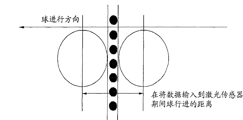
在铁杆击球(iron shot)的情况下,使用下面解释的矢量

下面给出了用于计算铁杆击球的球速的方程。The equations used to calculate ball speed for iron shots are given below.
方程2
T=n/fT=n/f
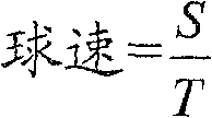
这里,T是时间,f是采样频率,n是相对于球经过传感器时遮挡每个传感器的球的数据排列的数量中的差,S是直到球被每个传感器感测到时球在三维空间中行进的距离(即,从球被第二水平传感器阵列感测的空间到球被第三水平传感器阵列感测的空间的距离,或者从球被第二水平传感器阵列感测的空间到球被垂直传感器阵列感测的空间的距离)。Here, T is time, f is the sampling frequency, n is the difference in the number of data permutations of the ball that occludes each sensor relative to when the ball passes by the sensor, and S is the position of the ball in three-dimensional space until the ball is sensed by each sensor. The distance traveled in (i.e., the distance from the space where the ball is sensed by the second level sensor array to the space where the ball is sensed by the third level sensor array, or from the space where the ball is sensed by the second level sensor array to the space where the ball is The distance of the space sensed by the vertical sensor array).
下面是用于计算球杆头速度的方程。Below is the equation used to calculate club head speed.
方程3Equation 3
T=n/fT=n/f

这里,T是时间,f是采样频率,n是当球杆头经过每个传感器时球杆头廓影遮挡索引差,S是当球杆头经过每个传感器时球杆头行进的三维距离。此外,通过使用各个传感器之间的距离以及当球杆头经过每个传感器时的角度来计算S。Here, T is time, f is the sampling frequency, n is the club head silhouette occlusion index difference as the club head passes each sensor, and S is the three-dimensional distance traveled by the club head as it passes each sensor. Furthermore, S is calculated by using the distance between the respective sensors and the angle when the club head passes each sensor.
控制单元110使用由第三水平传感器阵列102c和垂直传感器阵列104检测的球廓影数据,以获得球的方向角度和球的发射角度。The
将参照图6来描述获得球的方向角度和发射角度的方法。A method of obtaining a direction angle and a launch angle of a ball will be described with reference to FIG. 6 .
当球经过第三水平传感器阵列102c时可检测球的方向角度,当球经过垂直传感器阵列104时可得出球的发射角度。这里,即使当由接收来自激光器150的输入的垂直传感器阵列104检测的球的高度相同时,球的方向角度也取决于球的侧向位置而变化,从而必须使用由第三水平传感器阵列102c收集的方向角度来确定发射角度。When the ball passes the third
此外,在开球的情况下,球在空间中的位置和距离根据球座的高度而变化,从而必须输入球座的高度,以被反映到空间中的坐标。Also, in the case of a tee shot, the position and distance of the ball in space vary according to the height of the tee, so that the height of the tee must be input to be reflected in coordinates in space.
参照图6,位于球座上的球被击打,然后经过光层和激光层。当球经过光层时,球的廓影在第三水平传感器阵列102c的A点处形成,从该廓影获得球的中心点。Referring to FIG. 6, the ball on the tee is hit and then passes through the optical layer and the laser layer. When the ball passes through the photosphere, a silhouette of the ball is formed at point A of the third
接着,形成第一线以连接球的中心点A和激光器或安装在其上方的光源。同样地,当球经过激光层时,形成B点,从球的廓影获得球的中心点。Next, a first line is formed to connect the center point A of the ball to the laser or light source mounted above it. Likewise, when the ball passes through the laser layer, point B is formed, and the center point of the ball is obtained from the silhouette of the ball.
在三维空间中形成第二线以连接球的中心点B和安装在其后方的激光器。第一线和第二线在空间互不相交。A second line is formed in three-dimensional space to connect the center point B of the ball and the laser installed behind it. The first line and the second line do not intersect each other in space.
因此,可从在第三水平传感器阵列102c形成的球的廓影数据和在垂直传感器阵列104形成的球的廓影数据确定球在第一线和第二线上的位置。因此,在开球的情况下,球座的高度被输入,以确定球的发射位置。在铁杆击球的情况下,因为在指定的位置执行击球,所以自动确定球的发射位置。Accordingly, the position of the ball on the first and second lines can be determined from the ball's silhouette data formed at the third
当利用三维矢量描述三维球运动时,应用下面的方程。When describing three-dimensional ball motion using three-dimensional vectors, the following equations are applied.
P=(Px,Py,Pz):球第一次所在的空间坐标(在开球或铁杆击球的情况下球的位置)。P = (P x , P y , P z ): The coordinates in space where the ball was first located (the position of the ball in the case of a tee shot or an iron shot).
A=(Ax,Ay,Az):第三水平传感器阵列的球廓影的中心点(A点)。A=(A x , A y , A z ): the center point (point A) of the spherical silhouette of the third horizontal sensor array.
B=(Bx,By,Bz):垂直传感器阵列的球廓影的中心点(B点)。B=(B x , By y , B z ): the center point (point B) of the spherical silhouette of the vertical sensor array.
L=(Lx,Ly,Lz):安装在后方的激光器的空间坐标。L=(L x , L y , L z ): spatial coordinates of the laser installed at the rear.
M=(Mx,My,Mz):安装在上部的光源的空间坐标。M=(M x , M y , M z ): space coordinates of the light source installed on the upper part.
l1(第一线):连接A点和M点的直线的方程,l 1 (first line): the equation of the straight line connecting point A and point M,
l2(第二线):连接B点和L点的直线的方程,l 2 (second line): the equation of the straight line connecting points B and L,
现在,将推导从球的发射点P到第一线上的任意点的位置矢量。Now, the position vector from the launch point P of the ball to an arbitrary point on the first line will be derived.

这里,t是0和1之间的值。Here, t is a value between 0 and 1.
当t=0时,
当t=1时,
当t是0和1之间的值时,该矢量位于连接A点和M点的第一直线上。此外,M点和P点是空间中固定的点,从廓影数据计算出的A点也具有一个值,从而α1、α2、β1、β2、γ1和γ2都是常数,
类似地,可推导从球的发射点P到第二线上的任意点的位置矢量。Similarly, a position vector can be derived from the launch point P of the ball to any point on the second line.

这里,s是0和1之间的值。Here, s is a value between 0 and 1.
当s=0时,
当s=1时,
当s是0和1之间的值时,该矢量是位于连接L点和B点的第二直线上的点。此外,L点和P点是空间中固定的点,从廓影数据得出的B点也具有一个值,从而δ1、δ2、ε1、ε2、ζ1和ζ2都是常数,
第一线和第二线在空间不相交,但是因为球在一个方向上行进,所以矢量

(α1t+α2,β1t+β2,γ1t+γ2)=k(δ1s+δ2,ε1s+ε2,ζ1s+ζ2)。(α 1 t+α 2 , β 1 t+β 2 , γ 1 t+γ 2 )=k(δ 1 s+δ 2 , ε 1 s+ε 2 , ζ 1 s+ζ 2 ).
在上述方程中,α1、α2、β1、β2、γ1、γ2、δ1、δ2、ε1、ε2、ζ1和ζ2是在A点和B点从廓影数据得出的常数,t、s和k是变量。可从上面的矢量方程的矢量坐标x、y和z推导出三个方程,从而可求解出变量t、s和k。In the above equation, α 1 , α 2 , β 1 ,
由此可得出矢量

现在将参照图7至图15描述确定球质量的方法。A method of determining the mass of a ball will now be described with reference to FIGS. 7 to 15 .
控制单元110解析从水平传感器阵列102连续输出的数字数据(廓影检测数据),并确定球质量。The
当球与球杆撞击时,球的发射方向垂直于球杆面。由水平传感器阵列102的组件检测的廓影数据的点被连接,以沿着球杆边缘仅画出挥杆路径的圆形,从而获得当发生撞击时挥杆的圆弧的切线的倾斜。When the ball hits the club, the ball is launched perpendicular to the club face. The points of the silhouette data detected by the components of the
画出的圆形的路径是高尔夫球手的挥杆路径。在运动的每一点获得了路径的倾斜后,确定杆头的路径是外侧-内侧路径,内侧-内侧路径,还是内侧-外侧路径。The drawn circular path is the golfer's swing path. After obtaining the slope of the path at each point of motion, determine whether the path of the clubhead is an outside-inside path, inside-inside path, or inside-outside path.
图7显示了当发生撞击时挥杆的圆弧的切线没有倾斜,从而挥杆被解析为不存在任何侧旋的直飞球(straight)挥杆。Figure 7 shows that the tangent to the arc of the swing is not tilted when impact occurs, so that the swing is resolved as a straight swing without any side spin.
图8显示了当发生撞击时挥杆的圆弧的切线的倾斜,其中,倾斜朝向球的左侧(被确定为左曲球击打)。Figure 8 shows the slope of the tangent to the arc of the swing when impact occurs, where the slope is towards the left of the ball (determined as a hook shot).
图9显示了当发生撞击时挥杆的圆弧的切线的倾斜,其中,倾斜朝向球的右侧(被确定为右曲球击打)。Figure 9 shows the slope of the tangent to the arc of the swing when impact occurs, where the slope is towards the right of the ball (determined as a slice shot).
图10显示了当发生撞击时球的朝向右侧的发射方向以及挥杆的圆弧的切线没有倾斜,从而不存在侧旋(被确定为右推直飞球(push straight)击打)。Figure 10 shows the launch direction of the ball towards the right when impact occurs and the tangent to the arc of the swing is not tilted so that there is no side spin (identified as a push straight hit).
图11显示了当发生撞击时球的朝向右侧的发射方向以及挥杆的圆弧的切线的倾斜,其中,倾斜朝向球的左侧,以获得右推右曲球(push slice)。Figure 11 shows the direction of launch of the ball towards the right and the inclination of the tangent to the arc of the swing when impact occurs, wherein the inclination is towards the left of the ball for a push slice.
图12显示了当发生撞击时球的朝向右侧的发射方向以及挥杆的圆弧的切线的倾斜,其中,倾斜朝向球的右侧(被确定为右推左曲球(push hook)击打)。Figure 12 shows the launch direction of the ball towards the right and the inclination of the tangent to the arc of the swing when impact occurs, where the inclination is towards the right side of the ball (determined as a push hook) hit ).
图13显示了当发生撞击时球的朝向左侧的发射方向以及挥杆的圆弧的切线没有倾斜,(被确定为左拉直飞球(pull straight)击打)。Figure 13 shows the launch direction of the ball towards the left when impact occurs and the tangent to the arc of the swing is not tilted, (determined as a pull straight hit from the left).
图14显示了当发生撞击时球的朝向左侧的发射方向以及挥杆的圆弧的切线的倾斜,其中,倾斜朝向球的左侧(被确定为左拉右曲球(pull slice)击打)。Figure 14 shows the launch direction of the ball towards the left and the inclination of the tangent to the arc of the swing when impact occurs, where the inclination is towards the left side of the ball (determined as a pull slice) hit ).
图15显示了当发生撞击时球的朝向左侧的发射方向以及挥杆的圆弧的切线的倾斜,其中,倾斜朝向球的右侧(被确定为左拉左曲球(pull hook)击打)。Figure 15 shows the launch direction of the ball towards the left and the inclination of the tangent to the arc of the swing when impact occurs, where the inclination is towards the right of the ball (determined as a pull hook) hit ).
控制单元110考虑确定的球速、球杆头速度、球方向和发射角度、球杆接近路径等,以计算球的飞行路径。The
因此,飞行路径=f(球速,球杆头速度,方向角度,发射角度,球杆头路径)。Thus, flight path = f(ball speed, club head speed, heading angle, launch angle, club head path).
控制单元110使用由水平传感器阵列102和垂直传感器阵列104提供的检测的廓影数据,以计算球速、球杆头速度、球杆头路径、飞行路径等。The
显示单元120在高尔夫球训练场上的屏幕或FND上显示包括由控制单元110获得的球速、球杆头速度、方向角度、发射角度和球杆头路径的挥杆分析数据。The
数据输出单元130将由控制单元110计算的挥杆分析数据记录在预定的记录介质上。这里,可用常规的打印机代替数据输出单元130。The
虽然这里参照本发明的优选实施例描述和示出了本发明,但是对于本领域技术人员明显的是,在不脱离本发明的精神和范围的情况下,可以对其进行各种修改和变化。因此,本发明旨在覆盖权利要求及其等同物的范围内的本发明的修改和变化。While the present invention has been described and illustrated herein with reference to preferred embodiments thereof, it will be apparent to those skilled in the art that various modifications and changes can be made therein without departing from the spirit and scope of the invention. Thus, it is intended that the present invention cover the modifications and variations of this invention that come within the scope of the claims and their equivalents.
Claims (9)
Applications Claiming Priority (4)
| Application Number | Priority Date | Filing Date | Title |
|---|---|---|---|
| KR10-2005-0037209 | 2005-05-03 | ||
| KR1020050037209 | 2005-05-03 | ||
| KR1020050037209A KR100753657B1 (en) | 2005-05-03 | 2005-05-03 | Golf ball and head information analysis system |
| PCT/KR2006/001666 WO2006118422A1 (en) | 2005-05-03 | 2006-05-03 | Analysis system of golf ball and head information using lasers and 4 axis light sensing |
Publications (2)
| Publication Number | Publication Date |
|---|---|
| CN101171588A CN101171588A (en) | 2008-04-30 |
| CN101171588B true CN101171588B (en) | 2010-05-19 |
Family
ID=37308180
Family Applications (1)
| Application Number | Title | Priority Date | Filing Date |
|---|---|---|---|
| CN2006800150676A Active CN101171588B (en) | 2005-05-03 | 2006-05-03 | Analysis system of golf ball and club head information using laser and 4-axis optical sensing |
Country Status (4)
| Country | Link |
|---|---|
| US (1) | US8052543B2 (en) |
| KR (1) | KR100753657B1 (en) |
| CN (1) | CN101171588B (en) |
| WO (1) | WO2006118422A1 (en) |
Families Citing this family (36)
| Publication number | Priority date | Publication date | Assignee | Title |
|---|---|---|---|---|
| KR100977335B1 (en) * | 2008-01-10 | 2010-08-20 | 최성열 | Golf ball analysis system |
| KR100918302B1 (en) * | 2008-01-14 | 2009-09-22 | (주) 골프존 | Sensor device of simulation golf system and sensing method using it |
| KR100920949B1 (en) * | 2008-12-12 | 2009-10-09 | (주) 알디텍 | Sensing system to know the entrance angle, space velocity and strike point of club head in screen golf system |
| US9795845B2 (en) | 2009-01-20 | 2017-10-24 | Karsten Manufacturing Corporation | Golf club and golf club head structures |
| US9192831B2 (en) | 2009-01-20 | 2015-11-24 | Nike, Inc. | Golf club and golf club head structures |
| US9149693B2 (en) | 2009-01-20 | 2015-10-06 | Nike, Inc. | Golf club and golf club head structures |
| KR101133150B1 (en) * | 2009-06-02 | 2012-04-06 | 주식회사 원클릭 | A sensing device of golf ball and swing analyzerhaving the same |
| KR101157584B1 (en) * | 2009-06-18 | 2012-06-20 | 주식회사 유빅 | Golf ball dynamic information measurement unit of screen golf |
| JP5712217B2 (en) * | 2009-09-15 | 2015-05-07 | ソク、ジェイ ホSUK, Jey Ho | Method for measuring physical quantity of object using single light source and flat sensor unit, and system using the same |
| KR101248836B1 (en) * | 2010-06-07 | 2013-03-29 | (주) 알디텍 | Method and system for detecting an information of golf shot |
| IES86097B2 (en) * | 2010-11-22 | 2012-12-05 | Brian Francis Mooney | Determining and analysing movement and spin characteristics in a golf shot |
| US9687705B2 (en) | 2010-11-30 | 2017-06-27 | Nike, Inc. | Golf club head or other ball striking device having impact-influencing body features |
| JP5704317B2 (en) * | 2011-02-02 | 2015-04-22 | セイコーエプソン株式会社 | Swing analysis device, swing analysis system, program, and swing analysis method |
| US9409076B2 (en) | 2011-04-28 | 2016-08-09 | Nike, Inc. | Golf clubs and golf club heads |
| US9433845B2 (en) | 2011-04-28 | 2016-09-06 | Nike, Inc. | Golf clubs and golf club heads |
| US9375624B2 (en) | 2011-04-28 | 2016-06-28 | Nike, Inc. | Golf clubs and golf club heads |
| US9925433B2 (en) | 2011-04-28 | 2018-03-27 | Nike, Inc. | Golf clubs and golf club heads |
| US9433844B2 (en) | 2011-04-28 | 2016-09-06 | Nike, Inc. | Golf clubs and golf club heads |
| US9186547B2 (en) | 2011-04-28 | 2015-11-17 | Nike, Inc. | Golf clubs and golf club heads |
| US9409073B2 (en) | 2011-04-28 | 2016-08-09 | Nike, Inc. | Golf clubs and golf club heads |
| US20200276488A1 (en) * | 2011-05-11 | 2020-09-03 | Karsten Manufacturing Corporation | Systems, methods, and articles of manufacture to measure, analyze and share golf swing and ball motion characteristics |
| CN107583254B (en) | 2011-08-23 | 2020-03-27 | 耐克创新有限合伙公司 | Golf club head with cavity |
| KR101194269B1 (en) * | 2012-03-15 | 2012-10-29 | 주식회사 제니큐 | An equipment transferring golf ball position on 3d image screen to actual golf green and a golf game method using the equipment |
| US9416959B2 (en) | 2012-05-17 | 2016-08-16 | Donald Spinner | Illuminated golf |
| KR101412505B1 (en) * | 2013-11-28 | 2014-06-26 | (주) 알디텍 | Golf simulator, and golf simulation method |
| US9776050B2 (en) | 2014-06-20 | 2017-10-03 | Karsten Manufacturing Corporation | Golf club head or other ball striking device having impact-influencing body features |
| JP2016209228A (en) * | 2015-05-07 | 2016-12-15 | セイコーエプソン株式会社 | Swing analysis device, swing analysis method, swing analysis program, and swing analysis system provided with swing analysis device |
| JP5950068B1 (en) * | 2016-03-25 | 2016-07-13 | 株式会社Gpro | Ball bullet detection device and ball bullet detection method |
| US10226681B2 (en) | 2016-05-02 | 2019-03-12 | Nike, Inc. | Golf clubs and golf club heads having a plurality of sensors for detecting one or more swing parameters |
| US10220285B2 (en) | 2016-05-02 | 2019-03-05 | Nike, Inc. | Golf clubs and golf club heads having a sensor |
| US10137347B2 (en) | 2016-05-02 | 2018-11-27 | Nike, Inc. | Golf clubs and golf club heads having a sensor |
| JP6964905B2 (en) * | 2017-11-28 | 2021-11-10 | 株式会社ヴイシーVc Inc. | Distance measuring device and its control method |
| CN109107124A (en) * | 2018-09-26 | 2019-01-01 | 上海与德科技有限公司 | A kind of smart motion analogy method, device, system and storage medium |
| US10780332B1 (en) | 2019-12-06 | 2020-09-22 | Clay Lilleston | Laser golf swing trainer assembly |
| JP7005737B1 (en) * | 2020-12-28 | 2022-01-24 | 楽天グループ株式会社 | Golf swing analysis system, golf swing analysis method and program |
| US12370427B2 (en) * | 2022-08-23 | 2025-07-29 | Blast Motion Inc. | Putting biofeedback system that analyzes motion data |
Citations (1)
| Publication number | Priority date | Publication date | Assignee | Title |
|---|---|---|---|---|
| US5868578A (en) * | 1995-09-21 | 1999-02-09 | Baum; Charles S. | Sports analysis and testing system |
Family Cites Families (17)
| Publication number | Priority date | Publication date | Assignee | Title |
|---|---|---|---|---|
| US5575719A (en) * | 1994-02-24 | 1996-11-19 | Acushnet Company | Method and apparatus to determine object striking instrument movement conditions |
| US5348304A (en) * | 1993-07-12 | 1994-09-20 | Meade John C | Golf club swing training method |
| US5464220A (en) * | 1994-11-30 | 1995-11-07 | Hansen; Dale G. | Golf practice device and method |
| US5694340A (en) * | 1995-04-05 | 1997-12-02 | Kim; Charles Hongchul | Method of training physical skills using a digital motion analyzer and an accelerometer |
| WO1999030502A1 (en) * | 1997-12-10 | 1999-06-17 | Goszyk Kurt A | Three-dimensional object path tracking |
| JPH11206942A (en) | 1998-01-29 | 1999-08-03 | Pentel Kk | Golf ball flight distance measurement device |
| KR100364869B1 (en) * | 2000-06-26 | 2002-12-16 | 안찬습 | Method for removal of poison from the bark of Rhus Verniciflua |
| KR20020059003A (en) * | 2000-12-30 | 2002-07-12 | 현호경 | A golf game simulator |
| KR20020059562A (en) * | 2001-01-08 | 2002-07-13 | 서원호 | Golf exercise system |
| KR200261712Y1 (en) | 2001-09-13 | 2002-01-24 | 김형태 | golf training simulation apparatus |
| KR20030027143A (en) | 2001-09-13 | 2003-04-07 | 노현범 | Filter for sterilizing air in air-conditioner |
| US6804988B2 (en) * | 2001-09-19 | 2004-10-19 | Acushnet Company | Golf ball COR testing machine |
| KR100483666B1 (en) * | 2002-03-26 | 2005-04-18 | 주식회사 브이알필드 | A System for Measuring Flying Position and Velocity of Globe-Shaped Object Using the Light Fan Screen |
| KR20030085766A (en) * | 2002-05-01 | 2003-11-07 | 주식회사 미디어데이타시스템 | A golf shot analyzer and analyzing method using linear sensors |
| KR100358415B1 (en) * | 2002-07-29 | 2002-10-25 | 최승환 | Device and method for correcting golf swing using internet |
| US6669575B1 (en) * | 2003-01-16 | 2003-12-30 | Walter Terry Marlette | Golf shot shaper training aid |
| KR20050014928A (en) * | 2003-08-01 | 2005-02-21 | 김정태 | 3D golf swing analysis system and the method thereof |
-
2005
- 2005-05-03 KR KR1020050037209A patent/KR100753657B1/en not_active Expired - Lifetime
-
2006
- 2006-05-03 US US11/913,399 patent/US8052543B2/en active Active
- 2006-05-03 CN CN2006800150676A patent/CN101171588B/en active Active
- 2006-05-03 WO PCT/KR2006/001666 patent/WO2006118422A1/en not_active Ceased
Patent Citations (1)
| Publication number | Priority date | Publication date | Assignee | Title |
|---|---|---|---|---|
| US5868578A (en) * | 1995-09-21 | 1999-02-09 | Baum; Charles S. | Sports analysis and testing system |
Also Published As
| Publication number | Publication date |
|---|---|
| KR20060114969A (en) | 2006-11-08 |
| CN101171588A (en) | 2008-04-30 |
| KR100753657B1 (en) | 2007-08-31 |
| WO2006118422A1 (en) | 2006-11-09 |
| US20080153613A1 (en) | 2008-06-26 |
| US8052543B2 (en) | 2011-11-08 |
Similar Documents
| Publication | Publication Date | Title |
|---|---|---|
| CN101171588B (en) | Analysis system of golf ball and club head information using laser and 4-axis optical sensing | |
| KR101385323B1 (en) | Virtual sports system using start sensors | |
| US6821211B2 (en) | Sport swing analysis system | |
| US4858922A (en) | Method and apparatus for determining the velocity and path of travel of a ball | |
| US5906547A (en) | Golf simulation system | |
| EP2409735B1 (en) | Method and system for golf ball fitting analysis | |
| US8409024B2 (en) | Trajectory detection and feedback system for golf | |
| JP3749072B2 (en) | Golf club selection method and selection system | |
| CN109562289B (en) | Ball flight information computing device, ball flight information computing method, and computing device readable recording medium for recording the same | |
| CN102245269B (en) | Sensing system for sensing angle of incidence and point of impact | |
| JP5334185B2 (en) | Virtual golf simulator and sensing device provided therein | |
| JP4271615B2 (en) | Golf club head behavior measuring device | |
| CN102939137A (en) | Golf shot information measuring system and method | |
| KR100918302B1 (en) | Sensor device of simulation golf system and sensing method using it | |
| KR20020092266A (en) | Hybrid Golf System | |
| JP2003190352A (en) | Optimum capture support system for golf course | |
| KR102009271B1 (en) | Smart stick and terminal for virtual reality game | |
| KR20050076084A (en) | Optical sensing apparatus for golf simulator and manufacturing method therefore | |
| KR102915222B1 (en) | Distance recommendation device for providing recommendation distance at third location | |
| KR102712351B1 (en) | Distance recommendation device for providing recommendation distance at third location | |
| JP5034716B2 (en) | Test hitting device | |
| JP7248330B2 (en) | Multi-sensor tracking system and method | |
| CN119072346A (en) | Method, system, and non-transitory computer-readable recording medium for providing information on a golf shot | |
| KR20250093634A (en) | Virtual golf device and virtual golf system informing putting information | |
| KR101531674B1 (en) | Estimation of direction and orientation of clubhead analyzing golf ball spin vector at impact |
Legal Events
| Date | Code | Title | Description |
|---|---|---|---|
| C06 | Publication | ||
| PB01 | Publication | ||
| C10 | Entry into substantive examination | ||
| SE01 | Entry into force of request for substantive examination | ||
| C14 | Grant of patent or utility model | ||
| GR01 | Patent grant |