CN101153525B - Connecting/releasing mechanism and combination device - Google Patents
Connecting/releasing mechanism and combination device Download PDFInfo
- Publication number
- CN101153525B CN101153525B CN2006101447412A CN200610144741A CN101153525B CN 101153525 B CN101153525 B CN 101153525B CN 2006101447412 A CN2006101447412 A CN 2006101447412A CN 200610144741 A CN200610144741 A CN 200610144741A CN 101153525 B CN101153525 B CN 101153525B
- Authority
- CN
- China
- Prior art keywords
- hook
- branch components
- extreme direction
- moves
- branch
- Prior art date
- Legal status (The legal status is an assumption and is not a legal conclusion. Google has not performed a legal analysis and makes no representation as to the accuracy of the status listed.)
- Active
Links
Images


Classifications
-
- A—HUMAN NECESSITIES
- A61—MEDICAL OR VETERINARY SCIENCE; HYGIENE
- A61B—DIAGNOSIS; SURGERY; IDENTIFICATION
- A61B8/00—Diagnosis using ultrasonic, sonic or infrasonic waves
-
- A—HUMAN NECESSITIES
- A61—MEDICAL OR VETERINARY SCIENCE; HYGIENE
- A61B—DIAGNOSIS; SURGERY; IDENTIFICATION
- A61B8/00—Diagnosis using ultrasonic, sonic or infrasonic waves
- A61B8/44—Constructional features of the ultrasonic, sonic or infrasonic diagnostic device
- A61B8/4427—Device being portable or laptop-like
-
- A—HUMAN NECESSITIES
- A61—MEDICAL OR VETERINARY SCIENCE; HYGIENE
- A61B—DIAGNOSIS; SURGERY; IDENTIFICATION
- A61B8/00—Diagnosis using ultrasonic, sonic or infrasonic waves
- A61B8/44—Constructional features of the ultrasonic, sonic or infrasonic diagnostic device
- A61B8/4433—Constructional features of the ultrasonic, sonic or infrasonic diagnostic device involving a docking unit
-
- G—PHYSICS
- G06—COMPUTING OR CALCULATING; COUNTING
- G06F—ELECTRIC DIGITAL DATA PROCESSING
- G06F1/00—Details not covered by groups G06F3/00 - G06F13/00 and G06F21/00
- G06F1/16—Constructional details or arrangements
- G06F1/1613—Constructional details or arrangements for portable computers
- G06F1/1632—External expansion units, e.g. docking stations
-
- A—HUMAN NECESSITIES
- A61—MEDICAL OR VETERINARY SCIENCE; HYGIENE
- A61B—DIAGNOSIS; SURGERY; IDENTIFICATION
- A61B2560/00—Constructional details of operational features of apparatus; Accessories for medical measuring apparatus
- A61B2560/04—Constructional details of apparatus
- A61B2560/0456—Apparatus provided with a docking unit
-
- A—HUMAN NECESSITIES
- A61—MEDICAL OR VETERINARY SCIENCE; HYGIENE
- A61B—DIAGNOSIS; SURGERY; IDENTIFICATION
- A61B8/00—Diagnosis using ultrasonic, sonic or infrasonic waves
- A61B8/44—Constructional features of the ultrasonic, sonic or infrasonic diagnostic device
- A61B8/4405—Device being mounted on a trolley
-
- Y—GENERAL TAGGING OF NEW TECHNOLOGICAL DEVELOPMENTS; GENERAL TAGGING OF CROSS-SECTIONAL TECHNOLOGIES SPANNING OVER SEVERAL SECTIONS OF THE IPC; TECHNICAL SUBJECTS COVERED BY FORMER USPC CROSS-REFERENCE ART COLLECTIONS [XRACs] AND DIGESTS
- Y10—TECHNICAL SUBJECTS COVERED BY FORMER USPC
- Y10T—TECHNICAL SUBJECTS COVERED BY FORMER US CLASSIFICATION
- Y10T24/00—Buckles, buttons, clasps, etc.
- Y10T24/34—Combined diverse multipart fasteners
- Y10T24/3484—Hook
- Y10T24/3485—Hook and hook
- Y10T24/3487—Hook and hook having biasing spring
-
- Y—GENERAL TAGGING OF NEW TECHNOLOGICAL DEVELOPMENTS; GENERAL TAGGING OF CROSS-SECTIONAL TECHNOLOGIES SPANNING OVER SEVERAL SECTIONS OF THE IPC; TECHNICAL SUBJECTS COVERED BY FORMER USPC CROSS-REFERENCE ART COLLECTIONS [XRACs] AND DIGESTS
- Y10—TECHNICAL SUBJECTS COVERED BY FORMER USPC
- Y10T—TECHNICAL SUBJECTS COVERED BY FORMER US CLASSIFICATION
- Y10T24/00—Buckles, buttons, clasps, etc.
- Y10T24/34—Combined diverse multipart fasteners
- Y10T24/3484—Hook
- Y10T24/3485—Hook and hook
- Y10T24/3489—Hook and hook having securing means
-
- Y—GENERAL TAGGING OF NEW TECHNOLOGICAL DEVELOPMENTS; GENERAL TAGGING OF CROSS-SECTIONAL TECHNOLOGIES SPANNING OVER SEVERAL SECTIONS OF THE IPC; TECHNICAL SUBJECTS COVERED BY FORMER USPC CROSS-REFERENCE ART COLLECTIONS [XRACs] AND DIGESTS
- Y10—TECHNICAL SUBJECTS COVERED BY FORMER USPC
- Y10T—TECHNICAL SUBJECTS COVERED BY FORMER US CLASSIFICATION
- Y10T403/00—Joints and connections
- Y10T403/59—Manually releaseable latch type
- Y10T403/591—Manually releaseable latch type having operating mechanism
- Y10T403/593—Remotely actuated
Landscapes
- Health & Medical Sciences (AREA)
- Life Sciences & Earth Sciences (AREA)
- Engineering & Computer Science (AREA)
- Physics & Mathematics (AREA)
- Medical Informatics (AREA)
- Animal Behavior & Ethology (AREA)
- Radiology & Medical Imaging (AREA)
- Nuclear Medicine, Radiotherapy & Molecular Imaging (AREA)
- Biomedical Technology (AREA)
- Heart & Thoracic Surgery (AREA)
- Biophysics (AREA)
- Molecular Biology (AREA)
- Surgery (AREA)
- Pathology (AREA)
- General Health & Medical Sciences (AREA)
- Public Health (AREA)
- Veterinary Medicine (AREA)
- Theoretical Computer Science (AREA)
- Computer Hardware Design (AREA)
- Human Computer Interaction (AREA)
- General Engineering & Computer Science (AREA)
- General Physics & Mathematics (AREA)
- Ultra Sonic Daignosis Equipment (AREA)
Abstract
本发明提供一种能够简单的连接和断开两单元的连接/断开机构,以及具有这样连接/断开机构的组合装置。钩部具有钩,钩具有在其纵向前端形成有分支部件,分支部件具有向下朝向前端倾斜的前端侧面,同时在分支部件方向上施加弹力,钩利用施加在其上的外力在前端方向上移动并在外力消失时回到其初始位置,钩适于在与分支部件相对方向上移动到比分支部件长度更大范围的状态下相对于前端方向往复运动,钩座部具有:适于由钩的前端推动且当钩在前端方向移动时也移动的邻接元件;以及钩座,它适于先于钩在前端方向移动与分支接合,并当钩在前端方向移动时适于在与分支脱离状态下与邻接元件一同移动。
The present invention provides a connection/disconnection mechanism capable of simply connecting and disconnecting two units, and a combined device having such a connection/disconnection mechanism. The hook portion has a hook, the hook has a branch part formed at its longitudinal front end, the branch part has a front end side inclined downward toward the front end, while exerting elastic force in the direction of the branch part, and the hook moves in the front end direction by an external force applied thereto And return to its original position when the external force disappears, the hook is suitable for reciprocating movement relative to the front end direction in the state of moving to a larger range than the length of the branch part in the direction opposite to the branch part, the hook seat part has: an abutment element that is pushed by the front end and that also moves when the hook moves in the front end direction; and a hook seat adapted to engage the branch prior to the movement of the hook in the front end direction and adapted to disengage from the branch when the hook moves in the front end direction Move with adjacent elements.
Description
技术领域 technical field
本发明涉及一种连接/断开机构,并且更具体地涉及一种具有分别设置在两个连接和断开元件上的钩部和钩座部的连接/断开机构,以及具有连接/断开机构的组合装置。The present invention relates to a connection/disconnection mechanism, and more particularly to a connection/disconnection mechanism having a hook and a hook seat respectively provided on two connection and disconnection elements, and a connection/disconnection mechanism having Mechanism combination.
背景技术 Background technique
连接/断开机构用于将两元件机械的连接和断开。连接/断开机构包括分别设置在两个元件上的钩部和钩座部。两个单元通过钩部和钩座部件的接合连接起来,并通过两部件的脱离而断开(查看,例如,专利文件1)A connect/disconnect mechanism is used to mechanically connect and disconnect two components. The connection/disconnection mechanism includes a hook portion and a hook seat portion respectively provided on the two elements. The two units are connected by engagement of the hook and hook seat parts, and are disconnected by disengagement of the two parts (see, for example, Patent Document 1)
专利文件1Patent Document 1
日本专利待审公开No.2006-037511。Japanese Patent Laid-Open Publication No. 2006-037511.
发明内容 Contents of the invention
本发明解决的问题Problems solved by the present invention
已知的不同结构的连接/断开机构,依赖于应用目的的类型。例如,在两部件之一是便携式超声诊断设备以及另一个是用于功能扩展和轮子移动的且具有电子电路的停靠台的情况下,两部件能够可以简单的连接和断开是有必要的。Different structures of connection/disconnection mechanisms are known, depending on the type of application purpose. For example, where one of the two parts is a portable ultrasonic diagnostic device and the other is a docking station with electronic circuits for function expansion and wheel movement, it is necessary that the two parts can be easily connected and disconnected.
相应的,本发明的一个目的是提供一种能够简单的连接和断开两个单元的连接/断开机构,以及具有连接/断开机构的组合装置。Accordingly, an object of the present invention is to provide a connecting/disconnecting mechanism capable of simply connecting and disconnecting two units, and a combined device having the connecting/disconnecting mechanism.
解决问题的方法way of solving the problem
为解决上述问题,本发明的一方面提供一种具有分别设置在两个连接和断开单元上的钩部和钩座部的连接/断开机构,钩部具有在其纵向前端形成有分支部件的钩,分支部件具有向下朝向前端倾斜的前端侧面,同时在分支部件方向上施加弹力,钩利用施加在其上的外力在前端方向上移动并在外力消失时回到其初始位置,在与分支部件相对方向上移动到比分支部件长度更大范围的状态下,钩适于相对于前端方向往复运动,钩座部具有:适于由钩的前端推动且当钩在前端方向移动时也移动的邻接元件;以及钩座,它适于先于钩在前端方向移动与分支接合,并当钩在前端方向移动时适于在与分支脱离状态下与邻接元件一同移动。In order to solve the above-mentioned problems, an aspect of the present invention provides a connection/disconnection mechanism having a hook portion and a hook seat portion respectively provided on two connection and disconnection units, the hook portion having a branch part formed at its longitudinal front end For the hook, the branch part has a front side inclined downward toward the front end, while exerting an elastic force in the direction of the branch part, the hook moves in the front end direction using an external force applied thereto and returns to its original position when the external force disappears, and In the state where the branch part moves to a range larger than the length of the branch part in the relative direction, the hook is adapted to reciprocate relative to the front end direction, and the hook seat part has: adapted to be pushed by the front end of the hook and also move when the hook moves in the front end direction and a hook seat adapted to engage with the branch in advance of the movement of the hook in the forward direction, and adapted to move together with the adjacent member in a disengaged state from the branch when the hook moves in the forward direction.
为解决上述问题,本发明的另一方面用提供包括两个连接和断开单元的组合装置,该两个单元分别具有钩部和钩座部,钩部具有在其纵向前端形成有分支部件的钩,分支部件具有向下朝向前端倾斜的前端侧面,同时在分支部件方向上施加弹力,钩利用施加在其上的外力在前端方向上移动并在外力消失时回到其初始位置,钩适于在与分支部件相对方向上移动到比分支部件长度更大范围的状态下相对于前端方向往复运动,钩座部具有:适于由钩的前端推动且当钩在前端方向移动时也移动的邻接元件;以及钩座,它适于先于钩在前端方向移动与分支接合,并当钩在前端方向移动时适于在与分支脱离状态下与邻接元件一同移动。In order to solve the above-mentioned problems, another aspect of the present invention is to provide a combined device comprising two connecting and disconnecting units, the two units respectively have a hook portion and a hook seat portion, the hook portion has a branch part formed at its longitudinal front end. The hook, the branch part has a front end side inclined downward toward the front end, while exerting elastic force in the direction of the branch part, the hook moves in the front end direction using an external force applied thereto and returns to its original position when the external force disappears, the hook is suitable for Reciprocating relative to the front end direction in a state of moving in a direction opposite to the branch part to a range greater than the length of the branch part, the hook seat part has an abutment adapted to be pushed by the front end of the hook and also move when the hook moves in the front end direction an element; and a hook seat adapted to engage the branch prior to the movement of the hook in the forward direction and adapted to move with the adjoining member in disengagement from the branch when the hook moves in the forward direction.
为使断开操作简单化,优选的,钩部具有用于对钩施加外力的手柄。In order to simplify the disconnection operation, preferably, the hook portion has a handle for applying external force to the hook.
为提高连接强度,优选的,钩部具有多个钩部并且钩座部具有多个邻接元件,并且多个钩座与多个钩相对应。In order to improve connection strength, preferably, the hook portion has a plurality of hook portions and the hook seat portion has a plurality of adjoining elements, and the plurality of hook seats correspond to the plurality of hooks.
为进一步提高连接强度,优选的。钩部具有第二钩,其位置固定,并且钩座部优选的具有第二钩座,第二钩座适于在钩移动到前端方向之前与第二构相接合并适于与邻接元件一同移动,并且当钩移动到前端方向时其与第二钩相脱离。In order to further improve the connection strength, preferred. The hook portion has a second hook, which is fixed in position, and the hook seat portion preferably has a second hook seat adapted to engage with the second structure before the hook moves to the forward direction and adapted to move with the adjoining element , and it disengages from the second hook when the hook moves to the front end direction.
为建立电气连接,优选的,两单元之一具有电连接插头,其位置固定,并且,优选的,另一单元具有当钩座与钩的分支接合时用于与电连接插头相接合的电连接插座。To establish the electrical connection, preferably, one of the two units has an electrical connection plug, which is fixed in position, and, preferably, the other unit has an electrical connection for engaging the electrical connection plug when the hook seat engages with the branch of the hook socket.
为提供能够移动的组合装置,优选的,两单元之一为具有轮子移动的支撑基础,以及另一单元为能够安装到支撑基础上的电子设备。In order to provide a mobile combination, it is preferred that one of the two units is a supporting base with wheels for movement and the other unit is an electronic device which can be mounted to the supporting base.
为在连接时方便安置,优选的,支撑基础在其上表面具有引导轨道并在其底部具有用于电子设备的滑动器,滑动器与轨道相接合。For convenient placement when connected, preferably, the supporting base has guide rails on its upper surface and sliders for electronic equipment on its bottom, the sliders engaging with the rails.
为提供功能满意的组合装置,优选的,支撑基础具有用于电子设备的电子电路。In order to provide a functionally satisfactory combination, it is preferred that the supporting base has electronic circuitry for the electronic equipment.
为在使用电子设备时提高自由度,优选的,电子设备能够被从支撑基础移开并且便携的。In order to increase the degree of freedom when using the electronic equipment, it is preferable that the electronic equipment can be removed from the support base and be portable.
在使用时为得到具有高自由度的超声诊断设备,优选的,电子设备为超声诊断设备。In order to obtain an ultrasonic diagnostic device with a high degree of freedom in use, preferably, the electronic device is an ultrasonic diagnostic device.
在使用时为提供具有高自由度的超声诊断设备,优选的,电子设备为超声诊断设备。In order to provide an ultrasonic diagnostic device with a high degree of freedom in use, preferably, the electronic device is an ultrasonic diagnostic device.
发明效果Invention effect
根据本发明的相应连接/断开机构具有分别设置在两个连接和断开单元上的钩部和钩座部,钩部具有在其纵向前端形成有分支部件的钩,分支部件具有向下朝向前端倾斜的前端侧面,同时在分支部件方向上施加弹力,钩利用施加在其上的外力在前端方向上移动并在外力消失时回到其初始位置,钩适于在与分支部件相对方向上移动到比分支部件长度更大范围的状态下相对于前端方向往复运动,钩座部具有:适于由钩的前端推动且当钩在前端方向移动时也移动的邻接元件;以及钩座,它适于先于钩在前端方向移动与分支接合,并当钩在前端方向移动时适于在与分支脱离状态下与邻接元件一同移动。由此,提供能够简单的连接和断开两单元的连接/断开机构,以及具有这样连接/断开机构的组合装置是可能的。The corresponding connection/disconnection mechanism according to the present invention has a hook part and a hook seat part respectively provided on two connection and disconnection units, the hook part has a hook formed with a branch part at its longitudinal front end, and the branch part has a downward direction The side of the front end with an inclined front end, while exerting elastic force in the direction of the branch part, the hook moves in the direction of the front end using the external force applied to it and returns to its original position when the external force disappears, the hook is adapted to move in the direction opposite to the branch part To reciprocate relative to the front end direction in a state larger than the length of the branch part, the hook seat portion has: an abutting element adapted to be pushed by the front end of the hook and also to move when the hook moves in the front end direction; Engages with the branch prior to movement of the hook in the forward direction and is adapted to move with the adjoining element in disengagement from the branch when the hook moves in the forward direction. Thereby, it is possible to provide a connection/disconnection mechanism capable of simply connecting and disconnecting two units, and a combined device having such a connection/disconnection mechanism.
附图说明 Description of drawings
(原文安排在说明书的后面)(The original text is arranged at the back of the manual)
图1是以铜版纸照片的形式说明了实现本发明最好实例方式的结构;Fig. 1 has illustrated the structure realizing the best example mode of the present invention with the form of coated paper photo;
图2是以另一观点的铜版纸照片说明了实现本发明最好实例方式的结构;Fig. 2 has illustrated the structure of realizing the best example mode of the present invention with the coated paper photo of another point of view;
图3说明了顶端支承台的结构;Fig. 3 illustrates the structure of the top supporting platform;
图4说明了钩驱动机构的结构;Figure 4 illustrates the structure of the hook drive mechanism;
图5说明了钩的结构;Figure 5 illustrates the structure of the hook;
图6说明了钩的操作状态;Figure 6 illustrates the operational state of the hook;
图7说明了通过钩建立的连接状态;Figure 7 illustrates the state of a connection established through a hook;
图8说明了通过钩建立连接之前的状态;Figure 8 illustrates the state before the connection is established through the hook;
图9说明了断开连接的状态;Figure 9 illustrates the disconnected state;
图10说明了另一个钩驱动机构的结构;以及Figure 10 illustrates the structure of another hook drive mechanism; and
图11说明了芯轴的位置。Figure 11 illustrates the location of the mandrel.
附图标记的说明Explanation of reference signs
100,200:单元100, 200: units
112:邻接元件112: Adjacent element
210:顶端支撑台210: top support platform
220:台架220: Bench
222:手柄222: handle
240:平台240: platform
242:轨道242: Orbit
244:钩244: Hook
302:钩302: hook
310:托架310: bracket
312:支撑轴312: Support shaft
314:L型板314: L-shaped plate
316:盘簧316: coil spring
318:销钉318: pin
332:分支332: branch
334:铰链334: Hinge
501a,502b:芯轴501a, 502b: mandrel
实现本发明的优选方式The preferred way to realize the present invention
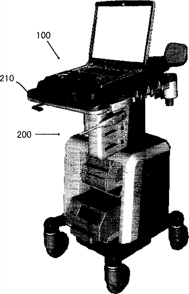
在这里将结合附图描述实现本发明的最佳方式。本发明不限于实现本发明的最佳方式。图1示出关于本发明超声诊断系统的外形立体图。该系统是为实现本发明的最佳方式的实例。关于该系统的结构,这里示出了实现本发明就组合装置的最佳方式的实例。此外,关于该系统结构的一部分,这里示出了实现本发明就连接/断开机构的最佳方式的实例。Here, the best mode for carrying out the present invention will be described with reference to the accompanying drawings. The invention is not limited to the best mode for carrying out the invention. FIG. 1 shows a perspective view of the appearance of the ultrasonic diagnostic system of the present invention. This system is an example of the best mode for carrying out the invention. Concerning the structure of the system, an example of the best mode of implementing the present invention in terms of combined devices is shown here. Also, regarding a part of the system structure, an example of the best mode for realizing the present invention with respect to the connection/disconnection mechanism is shown here.
如图1所示,该系统是通过两单元100和200结合建立的。一单元100为,例如,具有类似PC(个人计算机)笔记本大小外形的超声诊断设备。另一单元200为,例如,用于超声诊断设备的停靠台。停靠台具有用于超声诊断设备的功能扩展的电子电路,电源电路,以及其它附件。停靠台具有用于移动的轮子并且如推车的功用。As shown in FIG. 1 , the system is established by combining two
单元100不限于超声诊断设备,此外可以是适合的电子的或者非电子的设备。示意200不限于用于超声诊断设备的停靠台,此外可以是用于电子的或非电子的设备的支撑基础。这种情况下,并不是总需要用于移动的轮子。The
现在下面的描述是关于一个实施例,其中单元100和200分别为超声诊断设备和用于同一设备的停靠台。然而,同样在通过任何其它结合方式的组合装置的情况下,其可以得到同样的功能和效果。The following description now relates to an embodiment in which
超声诊断设备100置于停靠台200的水平顶端支撑台210上。这时,两者通过连接/断开机构相互机械连接,或者通过连接器电气连接。关于连接/断开机构,下面将给出描述。The ultrasonic
超声诊断设备100,与停靠台200一起,组成装备齐全的超声诊断系统。超声诊断设备100可以从停靠台200移开并且可以作为单独设备成为基本的超声诊断仪。既然超声诊断设备100具有类似PC笔记本大小的外形,它可以作为便携设备方便使用。The ultrasonic
图2示出超声诊断设备100和停靠台200从后面看的连接状态。如该同一图所示,超声诊断设备100的后表面邻接于顶端支撑台210的台架220的前侧,并且这时其相互机械的连接并且电气的连接。FIG. 2 shows a connection state of the ultrasonic
在台架220上设置能够推入的手柄222。通过向前推动手柄222,可以解除在超声诊断设备100和停靠台200之间的机械和电气连接。A push-in
图3示出顶端支撑台210的结构。如该同一图所示,顶端支撑台210具有两个台架220和230。台架220和230分别为后侧和前侧台架。平台240设置于后侧台架220和前侧台架230之间,并且超声诊断设备100置于平台240上。FIG. 3 shows the structure of the
一对钩302a和302b以及连接插头402从后侧台架220的前侧壁突出。钩302a,302b以及连接插头402分别与设置在超声诊断设备100后表面一侧的一对钩座和一连接件容纳部件相对应.A pair of
一对轨道242a和242b以及钩244设置在平台240上。轨道240a和240b布置在台架220的垂直方向。轨道242a,242b以及钩244分别与设置在超声诊断设备100底部的一对滑动器和钩座对应。A pair of
当超声诊断设备100按这样的方式置于平台240上,其后侧表面对着台架220的前表面,随后被推靠在具有作为引导器的轨道242a、242b的台架220上,钩302a,302b,244以及连接插头402与超声诊断设备100上的三个相应的钩座和连接件容纳部件相接合,由此在超声诊断设备100和停靠台200之间形成机械和电气连接。When the ultrasonic
图4示出用于钩302a和302b的驱动机构的结构。图4为顶端支撑台210的后视图。如该同一图所示,用于钩302a和302b的驱动机构安装在台架220内部的空间。FIG. 4 shows the structure of the drive mechanism for the
用于钩302a和302b的驱动机构具有托架310。具有U型横截面的托架310,可放松的安装在一对支撑轴312a和312b上,并且因此平行于台架220被支撑。The drive mechanism for the
支撑轴312a和312b沿托架310的垂直方向延伸,并且分别的其中一端固定在台架220的内壁,而其中另一端固定在一对L型板314a和314b的纵向板部位。L型板314a和314b的横向板部位固定在台架220的顶板上。The supporting
盘簧316a和316b装配在支撑轴312a和312b上、托架310与L型板314a和314b之间的位置,并且它们的排斥力施加在托架310和L型板314a,314b之间。由于排斥力,托架310不断的被推向台架220的内侧部分,并且停止在抵住挡块的支座上。这个位置是托架310的常规预定位置。The coil springs 316a and 316b are fitted on the
托架310顶部整体由手柄222构成。因此,当手柄222被手向前推,托架310抵抗盘簧316a和316b的排斥力前进,当手释放手柄222,托架310由于盘簧316a,316b的排斥力后退,并退回到其初始位置。The top of the
钩302a、302b与托架310的两端垂直连接。用于装配到托架310上的钩302a、302b的装配部位通过铰链形成,并且使钩302a、302b在顶部方向旋转的弹力施加到那些铰链上。The
钩302a、302b分别通过固定销钉318a和318b设置在顶部。销钉318a和318b可以阻止回复力引起的钩302a、302b的转动,并限制钩302a、302b的状态以便使其纵向方向与托架310前进和后退方向完全一致。在这样的限制状态的情况下,钩302a、302b与托架310一起前进和后退。
钩302a和302b的前端部沿台架220的前侧壁延伸并向外突出。当钩302a和302b向前移动,突出将变大,当钩302a和302b向后移动,突出将变小。连接插头402的前端部同样沿台架220的前侧壁延伸并向外突出。Front end portions of the
图5为用于钩302a和302b的驱动机构的侧视图。在图5中,钩302是钩302a和302b的通称,销钉318是销钉318a和318b的通称,以及支撑轴312是支撑轴312a和312b的通称。下文所述同样如此。Figure 5 is a side view of the drive mechanism for
如图5所示,钩302在纵向前端部分具有分支332。分支332的方向与作用在钩302上的旋转力方向相同。分支332的侧面按这样的方式倾斜,钩302的前端侧向前端下倾。As shown in FIG. 5, the
在钩302与销钉318接触的部位形成台阶部。台阶部在邻近铰链334一侧高并在远离铰链334一侧低。由于手柄222不使用时,例如,在它的预定常规位置,台阶部在它的低部位与销钉318接触,且分支332位于沿台阶部的低部分延伸的位置。A stepped portion is formed at a portion where the
如图6所示,在这样的状态下,当手柄222向前推,使钩302向前移动,台阶部的高部分与销钉318相接触,由此钩302前端部比较低。这样,有台阶部的钩302与销钉318一起组成凸轮机构。由于凸轮机构,全部的前端部的低部分比分支332的长度要大。钩302按前端部这样的降低状态向前移动。上述前进量和手柄222的压缩量相对应。As shown in FIG. 6, in this state, when the
当手释放手柄222时,钩302随回复力向后移动。结果是,钩302返回常规位置,此外,如图5所示,台阶部上的低部分与销钉318相接触并且钩302在其前端部提升的状态停止。When the hand releases the
图7示出了顶端支撑台210与超声诊断设备100相连接的状态。如图7(a)所示,钩302位于其常规位置并且当台阶部的低部分与销钉318接触时,其前端处于提升状态。在这种情况下,超声诊断设备100的后表面与顶端支承台210的台架220的前表面相接触,以及在钩302前端的分支332与在超声诊断设备100后表面上形成的钩座102相接合。超声诊断设备100相对于钩座102具有形成在其前端的低部分上的邻接元件112。由于钩302与钩座102相接合,邻接元件112不与钩302相接触。FIG. 7 shows a state where the tip supporting table 210 is connected to the ultrasonic
钩座102和邻接元件112分别设置着相对应的两个设在顶部的钩302。由此,通过在两个位置的钩302建立起连接。这时,如图7(b)所示,在顶端支承台210上的平台240上的钩244同样与形成在超声诊断设备100底部的钩座144相接合。接下来,超声诊断设备100与顶端支承台210在三个位置相连接。此外,从台架220突出的连接插头402与超声诊断设备100的连接件容纳部相连接,由此建立电气连接。The
通过向台架220的前表面推动超声诊断设备100的后表面,产生这样的连接。在这种情况下,如图8所示,首先,每个钩座102的低边与钩302的分支332的倾斜一侧表面相接触,以便于如果钩302的前端下降,当钩座102通过分支332的前端,钩座的低边就会在回复力的作用下突然立起,并与钩座102相接合。同时,钩244和钩座144同样相互接合。由此,可以通过简单的操作建立起超声诊断设备100与顶端支承板210间的连接来。Such connection is made by pushing the rear surface of the ultrasonic
图9示出了顶端支承板210与超声诊断设备100断开连接的状态。如图9(a)所示,当手柄222向前推,钩302向前移动并且当台阶部上的高部分与销钉318相接触时,其前端下降。FIG. 9 shows a state where the
由于前端部的降低量比分支332的长度要大,所以钩302和钩座102相互脱离。由于钩302的前端向前推进,当邻接元件112被推进,超声诊断设备100被向前推出去。结果,超声诊断设备100的后表面与台架220的前表面相脱离,并且连接插头402同样从连接件容纳部上脱离。这时如图9(b)所示,由于超声诊断设备100的移位,在设备100底部的钩座144就会从顶端支承台210上的平台240的钩244上脱离开。这样,超声诊断设备100与顶端支承台210的断开同样可以通过简单的操作实现。Since the lowering amount of the front end is greater than the length of the
托架310可以具有类似如图10所示的梁元件,例如由铝模铸制成,以替代具有U型截面的按压部。同样,托架310可以有沿其向前运动方向延伸的芯轴502a,502b。The
如图11所示,芯轴502a,502b的顶端在台架220的前侧壁暴露出。当托架310向前移动,它们的顶端使超声诊断设备100向前突出。芯轴502a,502b使超声诊断设备100突出更容易。As shown in FIG. 11 , the top ends of the
Claims (14)
- One kind have be separately positioned on two can connect be connected one of switching units be connected on hook portion be connected connection/release mechanism with hook seat section,Hook portion has:Be formed with the hook of branch components at its vertical front end, branch components has the downward front end side that tilts towards front end, apply elastic force in the branch components direction, the external force that the hook utilization applies thereon moves and gets back to its initial position at front extreme direction when external force disappears, hook is suitable for moving under the state more wider than branch components length with respect to front extreme direction reciprocating motion with the branch components relative direction at fore-endHook seat section has:Be suitable for the adjacent element that promotes and when being hooked in front extreme direction and moving, also move by the front end of hook; AndThe hook seat, it is suitable for moving with branch components and engaging prior to being hooked in front extreme direction, and when be hooked in be suitable for when front extreme direction moves with the branch components disengaged position under together mobile with adjacent element.
- 2. connection/release mechanism as claimed in claim 1, wherein hook portion has the handle that is suitable for hook is applied this external force, and this hook portion is connected to this handle.
- 3. connection/release mechanism as claimed in claim 1, wherein: hook portion has a plurality of hooks; And hook seat section has a plurality of adjacent elements, and a plurality of hook seat is corresponding with a plurality of hooks.
- 4. connection/release mechanism as claimed in claim 3, wherein: hook portion has the second hook, and the position of this second hook is fixed; AndHook seat section has the second hook seat, and the second hook seat is suitable for before extreme direction moves before this a plurality of being hooked in joining to merging with the second hook being suitable for adjacent element together mobilely, and itself and the second hook are separated when being hooked in front extreme direction and moving.
- 5. a composite set comprises that but two can connect and switching units, and these two unit have respectively hook portion and hook seat section,Hook portion has:Be formed with the hook of branch components at its vertical front end, branch components has the downward front end side that tilts towards front end, apply elastic force in the branch components direction, the external force that the hook utilization applies thereon moves and gets back to its initial position at front extreme direction when external force disappears, hook is suitable for moving under the state more wider than branch components length with respect to front extreme direction reciprocating motion with the branch components relative direction at fore-endHook seat section has:Be suitable for the adjacent element that promotes and when being hooked in front extreme direction and moving, also move by the front end of hook; AndThe hook seat, it is suitable for moving with branch components and engaging prior to being hooked in front extreme direction, and when be hooked in be suitable for when front extreme direction moves with the branch components disengaged position under together mobile with adjacent element.
- 6. composite set as claimed in claim 5, wherein hook portion has the handle that is suitable for hook is applied this external force, and this hook portion is connected to this handle.
- 7. composite set as claimed in claim 5, wherein: hook portion has a plurality of hooks; And hook seat section has a plurality of adjacent elements, and a plurality of hook seat is corresponding with a plurality of hooks.
- 8. composite set as claimed in claim 7, wherein: hook portion has the second hook, and the position of this second hook is fixed; AndHook seat section has the second hook seat, and the second hook seat is suitable for before these a plurality of hooks move to before the extreme direction joining to merging with the second hook being suitable for adjacent element together mobilely, and itself and the second hook are separated when hook moves to front extreme direction.
- 9. composite set as claimed in claim 8, wherein: one of Unit two have Electric plug with shutter, and the position of this Electric plug with shutter is fixed, and another unit has be used for the electric-connected socket that engages with Electric plug with shutter when the hook seat engages with the branch components of hook.
- 10. composite set as claimed in claim 9, wherein: one of Unit two are for having the brace foundation that wheel moves, andAnother unit is for being installed to the electronic equipment on the brace foundation.
- 11. described composite set as claimed in claim 10, wherein: brace foundation thereon surface has guide rail; AndElectronic equipment has slider in its bottom, and slider engages with track.
- 12. described composite set as claimed in claim 11, wherein brace foundation has the electronic circuit for electronic equipment.
- 13. described composite set as claimed in claim 12, wherein electronic equipment can be removed from brace foundation and is portable.
- 14. described composite set as claimed in claim 13, wherein electronic equipment is ultrasonic diagnostic equipment.
Priority Applications (3)
| Application Number | Priority Date | Filing Date | Title |
|---|---|---|---|
| CN2006101447412A CN101153525B (en) | 2006-09-30 | 2006-09-30 | Connecting/releasing mechanism and combination device |
| JP2007228504A JP5105472B2 (en) | 2006-09-30 | 2007-09-04 | Connection / release mechanism and compound device |
| US11/862,724 US7857541B2 (en) | 2006-09-30 | 2007-09-27 | Connecting/disconnecting mechanism and composite apparatus |
Applications Claiming Priority (1)
| Application Number | Priority Date | Filing Date | Title |
|---|---|---|---|
| CN2006101447412A CN101153525B (en) | 2006-09-30 | 2006-09-30 | Connecting/releasing mechanism and combination device |
Publications (2)
| Publication Number | Publication Date |
|---|---|
| CN101153525A CN101153525A (en) | 2008-04-02 |
| CN101153525B true CN101153525B (en) | 2013-01-09 |
Family
ID=39255383
Family Applications (1)
| Application Number | Title | Priority Date | Filing Date |
|---|---|---|---|
| CN2006101447412A Active CN101153525B (en) | 2006-09-30 | 2006-09-30 | Connecting/releasing mechanism and combination device |
Country Status (3)
| Country | Link |
|---|---|
| US (1) | US7857541B2 (en) |
| JP (1) | JP5105472B2 (en) |
| CN (1) | CN101153525B (en) |
Families Citing this family (27)
| Publication number | Priority date | Publication date | Assignee | Title |
|---|---|---|---|---|
| KR101068914B1 (en) * | 2008-07-03 | 2011-09-30 | 삼성메디슨 주식회사 | Ultrasonic Diagnostic Device |
| KR101068915B1 (en) * | 2008-07-03 | 2011-09-29 | 삼성메디슨 주식회사 | Medical devices |
| KR101068916B1 (en) * | 2008-07-03 | 2011-09-29 | 삼성메디슨 주식회사 | Medical devices |
| US8210548B1 (en) * | 2008-08-15 | 2012-07-03 | June Agyemang | Portable nursing service cart and associated method |
| CN101664337B (en) * | 2008-09-01 | 2012-11-07 | 株式会社东芝 | Trolley |
| JP5405070B2 (en) | 2008-09-03 | 2014-02-05 | 株式会社東芝 | Ultrasound diagnostic system and installation base for ultrasonic diagnostic equipment |
| US8511633B2 (en) * | 2009-01-16 | 2013-08-20 | Amazon Technologies, Inc. | Accessory attachment mechanism |
| US8199490B2 (en) * | 2009-01-31 | 2012-06-12 | Eran Wilkenfeld | Electronic device support system |
| KR20100116430A (en) * | 2009-04-22 | 2010-11-01 | 주식회사 메디슨 | Ultrasonic diagnostic apparatus |
| US8286977B2 (en) * | 2009-07-30 | 2012-10-16 | Mela Sciences, Inc. | Medical cart |
| US8381987B2 (en) | 2009-07-30 | 2013-02-26 | Mela Sciences, Inc. | Insertable storage card containing a portable memory card having a connection interface |
| US8439698B1 (en) | 2010-06-15 | 2013-05-14 | Amrinder Pal Singh Saini | Low profile mechanical and electrical accessory connector |
| USD650482S1 (en) * | 2010-11-16 | 2011-12-13 | Samsung Electronics Co., Ltd. | Ultrasonic diagnostic equipment |
| JP5786029B2 (en) * | 2011-09-30 | 2015-09-30 | 日立アロカメディカル株式会社 | Cart for portable ultrasonic diagnostic equipment and ultrasonic diagnostic unit |
| US9796344B2 (en) | 2011-10-13 | 2017-10-24 | SmartTray International, LLC | Electronic device support for vehicles |
| US9067682B2 (en) | 2011-10-13 | 2015-06-30 | Nick Pajic | Electronic device support for vehicles |
| US8667904B2 (en) | 2011-10-13 | 2014-03-11 | Nick Pajic | Aircraft tray table with electronic device support |
| US9403596B2 (en) * | 2011-10-13 | 2016-08-02 | SmartTray International, LLC | Tray table with rotatable inner tray and adjustable retention assembly |
| TW201445278A (en) * | 2013-05-20 | 2014-12-01 | 鴻海精密工業股份有限公司 | mobile power |
| US9466927B2 (en) | 2014-09-08 | 2016-10-11 | Apple Inc. | Docking station with integral device support structure |
| US9778690B2 (en) * | 2014-09-30 | 2017-10-03 | Apple Inc. | Adaptive docking station |
| CN106137406B (en) * | 2016-08-09 | 2019-04-26 | 柯尼卡美能达再启医疗设备(上海)有限公司 | Tray device |
| US10061354B2 (en) * | 2016-10-14 | 2018-08-28 | Gamber-Johnson Llc | Docking station for electronic device |
| EP3467613B1 (en) * | 2017-10-09 | 2024-10-30 | Getac Holdings Corporation | Engaging mechanism, transmission dock equipped with the same, and electronic apparatus having the same |
| IT201900001143A1 (en) * | 2019-01-25 | 2020-07-25 | Eurosets Srl | EQUIPMENT FOR TRANSPORTING BIOMEDICAL DEVICES |
| USD915603S1 (en) * | 2019-09-23 | 2021-04-06 | GE Precision Healthcare LLC | Accessory holder |
| CN115227519B (en) * | 2022-01-19 | 2023-06-02 | 苏州心擎医疗技术有限公司 | Carrier and oxygenator system using same |
Citations (3)
| Publication number | Priority date | Publication date | Assignee | Title |
|---|---|---|---|---|
| US6275378B1 (en) * | 1999-01-19 | 2001-08-14 | Compal Electronics, Inc. | Safety lock for notebook-type computer dock |
| CN1313569A (en) * | 2000-03-13 | 2001-09-19 | 石斌 | Medical image processing, diagnosing and reporting instrument |
| US20040150963A1 (en) * | 2003-01-31 | 2004-08-05 | Sonosite, Inc. | System for use with a modular apparatus for diagnostic ultrasound |
Family Cites Families (38)
| Publication number | Priority date | Publication date | Assignee | Title |
|---|---|---|---|---|
| JPS6244331U (en) * | 1985-09-02 | 1987-03-17 | ||
| DE8717891U1 (en) * | 1987-02-21 | 1990-12-06 | Dr.-Ing. Rudolf Hell Gmbh, 2300 Kiel | Clamping device for image cylinder |
| CA1310693C (en) * | 1988-01-27 | 1992-11-24 | Manfred Prokopp | Electrical connecting apparatus for an electrical or electronic testing unit |
| US5580182A (en) * | 1995-06-07 | 1996-12-03 | Inventec Corporation | Computer peripheral engagement/disengagement mechanism |
| JPH09269848A (en) * | 1996-03-28 | 1997-10-14 | Internatl Business Mach Corp <Ibm> | Docking device for portable computer |
| US5926627A (en) * | 1996-04-26 | 1999-07-20 | Canon Kabushiki Kaisha | Electronic apparatus for engaging a portable computer with an expansion unit |
| JPH09329110A (en) * | 1996-06-10 | 1997-12-22 | Canon Inc | Unit coupling device and image forming apparatus |
| JPH1091282A (en) * | 1996-09-10 | 1998-04-10 | Canon Inc | Electronic equipment |
| KR100206114B1 (en) * | 1996-10-11 | 1999-07-01 | 윤종용 | External input / output connection adaptive video line connection device |
| US6034869A (en) * | 1996-12-20 | 2000-03-07 | Compaq Computer Corporation | Locking apparatus for locking a notebook computer on a docking station |
| KR100233027B1 (en) * | 1997-04-15 | 1999-12-01 | 윤종용 | An ejecting apparatus and an expansion system for portable computer provided with the same |
| US6366458B1 (en) * | 1997-06-30 | 2002-04-02 | Sony Corporation | Docking unit for portable electronic device and locking method of docking unit |
| KR100315561B1 (en) * | 1998-01-13 | 2002-02-28 | 윤종용 | Expansion apparatus |
| US6069790A (en) * | 1998-01-27 | 2000-05-30 | Dell Usa, L.P. | Portable computer ejection mechanism for docking devices |
| US6297953B1 (en) * | 1998-04-30 | 2001-10-02 | Hewlett-Packard Company | Alignment mechanism for computer system having a portable computer and docking station |
| JP2000030810A (en) * | 1998-07-07 | 2000-01-28 | Seiko Instruments Inc | Power supply connection device and electronic apparatus having the power supply connection device |
| US6093039A (en) * | 1998-08-06 | 2000-07-25 | Mobility Electronics, Inc. | Docking device for a portable computer |
| US6424524B2 (en) * | 1998-08-21 | 2002-07-23 | Compaq Information Technologies Group, L.P. | Wedge-shaped port replicator for portable computer |
| US6113409A (en) * | 1998-10-05 | 2000-09-05 | Samsung Electronics Co., Ltd. | Connecting apparatus for cartridge of learning device |
| US6216195B1 (en) * | 1999-02-01 | 2001-04-10 | Compal Electronics, Inc. | Docking station for a notebook computer |
| US6061234A (en) * | 1999-03-15 | 2000-05-09 | Dell U.S.A., L.P. | Secured snap-on cover for a computer system docking station |
| US6560101B1 (en) * | 2000-07-28 | 2003-05-06 | Hewlett-Packard Company | Alignment mechanism for a computer system having a portable computer and a docking station |
| JP3581318B2 (en) * | 2001-02-06 | 2004-10-27 | 株式会社東芝 | Cooling device used for electronic equipment system and portable electronic equipment |
| JP3661855B2 (en) * | 2001-08-30 | 2005-06-22 | タイコエレクトロニクスアンプ株式会社 | Wire pressure welding device with wire tip alignment mechanism |
| TW547905U (en) * | 2002-06-13 | 2003-08-11 | Wistron Corp | Fastener |
| US6741462B2 (en) * | 2002-07-16 | 2004-05-25 | Dell Products L.P. | Compact, low friction ejection mechanism for notebook docking station |
| KR100906248B1 (en) * | 2002-10-16 | 2009-07-07 | 삼성전자주식회사 | Docking station and laptop computer using same |
| US7256990B2 (en) * | 2003-08-29 | 2007-08-14 | Dell Products L.P. | Vertical docking method and system |
| US7085132B2 (en) * | 2003-11-24 | 2006-08-01 | Dell Products L.P. | Vertically docking an information handling system to a media slice |
| KR100703657B1 (en) * | 2004-06-28 | 2007-04-05 | 엘지전자 주식회사 | Port replicator |
| JP4043034B2 (en) | 2004-07-27 | 2008-02-06 | タキゲン製造株式会社 | Receiving device for edge-mounted lock handle device |
| US7298613B2 (en) * | 2004-09-23 | 2007-11-20 | Hewlett-Packard Development Company, L.P. | Portable computer docking station |
| US7139168B2 (en) * | 2004-10-28 | 2006-11-21 | Hewlett-Packard Development Company, L.P. | Docking station |
| US7142421B2 (en) * | 2004-12-28 | 2006-11-28 | Inventec Corporation | Docking station for locking a notebook computer |
| JP4220524B2 (en) * | 2006-01-31 | 2009-02-04 | 株式会社東芝 | Connected device |
| CN101093404B (en) * | 2006-06-23 | 2011-07-27 | 鸿富锦精密工业(深圳)有限公司 | Clipping united set, and expanding slot of using the set |
| US7480139B2 (en) * | 2006-10-25 | 2009-01-20 | Hewlett-Packard Development Company, L.P. | Electronic device docking system |
| TWI326402B (en) * | 2007-04-13 | 2010-06-21 | Inventec Corp | Docking station |
-
2006
- 2006-09-30 CN CN2006101447412A patent/CN101153525B/en active Active
-
2007
- 2007-09-04 JP JP2007228504A patent/JP5105472B2/en active Active
- 2007-09-27 US US11/862,724 patent/US7857541B2/en active Active
Patent Citations (3)
| Publication number | Priority date | Publication date | Assignee | Title |
|---|---|---|---|---|
| US6275378B1 (en) * | 1999-01-19 | 2001-08-14 | Compal Electronics, Inc. | Safety lock for notebook-type computer dock |
| CN1313569A (en) * | 2000-03-13 | 2001-09-19 | 石斌 | Medical image processing, diagnosing and reporting instrument |
| US20040150963A1 (en) * | 2003-01-31 | 2004-08-05 | Sonosite, Inc. | System for use with a modular apparatus for diagnostic ultrasound |
Also Published As
| Publication number | Publication date |
|---|---|
| US7857541B2 (en) | 2010-12-28 |
| CN101153525A (en) | 2008-04-02 |
| JP2008089178A (en) | 2008-04-17 |
| JP5105472B2 (en) | 2012-12-26 |
| US20080078071A1 (en) | 2008-04-03 |
Similar Documents
| Publication | Publication Date | Title |
|---|---|---|
| CN101153525B (en) | Connecting/releasing mechanism and combination device | |
| US5687061A (en) | Expansion base and system for portable computers | |
| TWI783647B (en) | Tray for expansion device and server having the same | |
| WO2014000579A1 (en) | Linkage apparatus for plugging pcb | |
| CN111769404A (en) | Electrical connector plug-in mechanism | |
| JP2019032643A (en) | Electronic apparatus | |
| TWI507850B (en) | Support bracket | |
| JP5454855B2 (en) | Cart for diagnostic imaging equipment | |
| US20180074548A1 (en) | Docking station for a mobile electronic device and operating method for the same | |
| TW201322838A (en) | Circuit board assembly, electronic device having the same, and lifting and lowering apparatus thereof | |
| CN107918452A (en) | Computer module with tablet computer part and base part | |
| CN203809990U (en) | Electronic device support frame | |
| TW201309161A (en) | Linkage device | |
| CN105530794A (en) | cable management rack | |
| CN107432095B (en) | Support equipment and support methods | |
| KR20060119084A (en) | Portable computer with detachable display | |
| TWM439830U (en) | Monitor having quick release function | |
| CN111641065B (en) | Telescopic transmission mechanism and electronic device expansion seat | |
| CN211879689U (en) | Battery plugging mechanism | |
| TWI890348B (en) | Electronic device | |
| CN115514832A (en) | A stretchable screen structure and electronic equipment | |
| JP4524244B2 (en) | Sheet connector connection structure | |
| CN112573433B (en) | A sand table for engineering management with adjustable usable area | |
| CN220904856U (en) | Mobile phone support and vehicle | |
| CN114156692B (en) | A disassembly structure for assisting the separation of male and female ends of a small connector |
Legal Events
| Date | Code | Title | Description |
|---|---|---|---|
| C06 | Publication | ||
| PB01 | Publication | ||
| C10 | Entry into substantive examination | ||
| SE01 | Entry into force of request for substantive examination | ||
| C14 | Grant of patent or utility model | ||
| GR01 | Patent grant |