CN101146486B - Low profile spinal tethering devices - Google Patents
Low profile spinal tethering devices Download PDFInfo
- Publication number
- CN101146486B CN101146486B CN2006800093739A CN200680009373A CN101146486B CN 101146486 B CN101146486 B CN 101146486B CN 2006800093739 A CN2006800093739 A CN 2006800093739A CN 200680009373 A CN200680009373 A CN 200680009373A CN 101146486 B CN101146486 B CN 101146486B
- Authority
- CN
- China
- Prior art keywords
- staple
- tether
- spinal anchoring
- anchoring device
- spinal
- Prior art date
- Legal status (The legal status is an assumption and is not a legal conclusion. Google has not performed a legal analysis and makes no representation as to the accuracy of the status listed.)
- Expired - Lifetime
Links
Images


Classifications
-
- A—HUMAN NECESSITIES
- A61—MEDICAL OR VETERINARY SCIENCE; HYGIENE
- A61B—DIAGNOSIS; SURGERY; IDENTIFICATION
- A61B17/00—Surgical instruments, devices or methods
- A61B17/56—Surgical instruments or methods for treatment of bones or joints; Devices specially adapted therefor
- A61B17/58—Surgical instruments or methods for treatment of bones or joints; Devices specially adapted therefor for osteosynthesis, e.g. bone plates, screws or setting implements
- A61B17/68—Internal fixation devices, including fasteners and spinal fixators, even if a part thereof projects from the skin
- A61B17/70—Spinal positioners or stabilisers, e.g. stabilisers comprising fluid filler in an implant
- A61B17/7053—Spinal positioners or stabilisers, e.g. stabilisers comprising fluid filler in an implant with parts attached to bones or to each other by flexible wires, straps, sutures or cables
-
- A—HUMAN NECESSITIES
- A61—MEDICAL OR VETERINARY SCIENCE; HYGIENE
- A61B—DIAGNOSIS; SURGERY; IDENTIFICATION
- A61B17/00—Surgical instruments, devices or methods
- A61B17/064—Surgical staples, i.e. penetrating the tissue
- A61B17/0642—Surgical staples, i.e. penetrating the tissue for bones, e.g. for osteosynthesis or connecting tendon to bone
-
- A—HUMAN NECESSITIES
- A61—MEDICAL OR VETERINARY SCIENCE; HYGIENE
- A61B—DIAGNOSIS; SURGERY; IDENTIFICATION
- A61B17/00—Surgical instruments, devices or methods
- A61B17/16—Instruments for performing osteoclasis; Drills or chisels for bones; Trepans
- A61B17/1662—Instruments for performing osteoclasis; Drills or chisels for bones; Trepans for particular parts of the body
- A61B17/1671—Instruments for performing osteoclasis; Drills or chisels for bones; Trepans for particular parts of the body for the spine
-
- A—HUMAN NECESSITIES
- A61—MEDICAL OR VETERINARY SCIENCE; HYGIENE
- A61B—DIAGNOSIS; SURGERY; IDENTIFICATION
- A61B17/00—Surgical instruments, devices or methods
- A61B17/56—Surgical instruments or methods for treatment of bones or joints; Devices specially adapted therefor
- A61B17/58—Surgical instruments or methods for treatment of bones or joints; Devices specially adapted therefor for osteosynthesis, e.g. bone plates, screws or setting implements
- A61B17/68—Internal fixation devices, including fasteners and spinal fixators, even if a part thereof projects from the skin
- A61B17/70—Spinal positioners or stabilisers, e.g. stabilisers comprising fluid filler in an implant
- A61B17/7001—Screws or hooks combined with longitudinal elements which do not contact vertebrae
- A61B17/7002—Longitudinal elements, e.g. rods
- A61B17/701—Longitudinal elements with a non-circular, e.g. rectangular, cross-section
-
- A—HUMAN NECESSITIES
- A61—MEDICAL OR VETERINARY SCIENCE; HYGIENE
- A61B—DIAGNOSIS; SURGERY; IDENTIFICATION
- A61B17/00—Surgical instruments, devices or methods
- A61B17/56—Surgical instruments or methods for treatment of bones or joints; Devices specially adapted therefor
- A61B17/58—Surgical instruments or methods for treatment of bones or joints; Devices specially adapted therefor for osteosynthesis, e.g. bone plates, screws or setting implements
- A61B17/68—Internal fixation devices, including fasteners and spinal fixators, even if a part thereof projects from the skin
- A61B17/70—Spinal positioners or stabilisers, e.g. stabilisers comprising fluid filler in an implant
- A61B17/7001—Screws or hooks combined with longitudinal elements which do not contact vertebrae
- A61B17/7002—Longitudinal elements, e.g. rods
- A61B17/7019—Longitudinal elements having flexible parts, or parts connected together, such that after implantation the elements can move relative to each other
- A61B17/7022—Tethers, i.e. longitudinal elements capable of transmitting tension only, e.g. straps, sutures or cables
-
- A—HUMAN NECESSITIES
- A61—MEDICAL OR VETERINARY SCIENCE; HYGIENE
- A61B—DIAGNOSIS; SURGERY; IDENTIFICATION
- A61B17/00—Surgical instruments, devices or methods
- A61B17/56—Surgical instruments or methods for treatment of bones or joints; Devices specially adapted therefor
- A61B17/58—Surgical instruments or methods for treatment of bones or joints; Devices specially adapted therefor for osteosynthesis, e.g. bone plates, screws or setting implements
- A61B17/68—Internal fixation devices, including fasteners and spinal fixators, even if a part thereof projects from the skin
- A61B17/70—Spinal positioners or stabilisers, e.g. stabilisers comprising fluid filler in an implant
- A61B17/7001—Screws or hooks combined with longitudinal elements which do not contact vertebrae
- A61B17/7035—Screws or hooks, wherein a rod-clamping part and a bone-anchoring part can pivot relative to each other
- A61B17/704—Screws or hooks, wherein a rod-clamping part and a bone-anchoring part can pivot relative to each other the longitudinal element passing through a ball-joint in the screw head
-
- A—HUMAN NECESSITIES
- A61—MEDICAL OR VETERINARY SCIENCE; HYGIENE
- A61B—DIAGNOSIS; SURGERY; IDENTIFICATION
- A61B17/00—Surgical instruments, devices or methods
- A61B17/56—Surgical instruments or methods for treatment of bones or joints; Devices specially adapted therefor
- A61B17/58—Surgical instruments or methods for treatment of bones or joints; Devices specially adapted therefor for osteosynthesis, e.g. bone plates, screws or setting implements
- A61B17/68—Internal fixation devices, including fasteners and spinal fixators, even if a part thereof projects from the skin
- A61B17/84—Fasteners therefor or fasteners being internal fixation devices
- A61B17/86—Pins or screws or threaded wires; nuts therefor
- A61B17/8695—Washers
-
- A—HUMAN NECESSITIES
- A61—MEDICAL OR VETERINARY SCIENCE; HYGIENE
- A61B—DIAGNOSIS; SURGERY; IDENTIFICATION
- A61B17/00—Surgical instruments, devices or methods
- A61B17/56—Surgical instruments or methods for treatment of bones or joints; Devices specially adapted therefor
- A61B17/58—Surgical instruments or methods for treatment of bones or joints; Devices specially adapted therefor for osteosynthesis, e.g. bone plates, screws or setting implements
- A61B17/88—Osteosynthesis instruments; Methods or means for implanting or extracting internal or external fixation devices
- A61B17/8875—Screwdrivers, spanners or wrenches
- A61B17/8877—Screwdrivers, spanners or wrenches characterised by the cross-section of the driver bit
-
- A—HUMAN NECESSITIES
- A61—MEDICAL OR VETERINARY SCIENCE; HYGIENE
- A61B—DIAGNOSIS; SURGERY; IDENTIFICATION
- A61B17/00—Surgical instruments, devices or methods
- A61B17/56—Surgical instruments or methods for treatment of bones or joints; Devices specially adapted therefor
- A61B17/58—Surgical instruments or methods for treatment of bones or joints; Devices specially adapted therefor for osteosynthesis, e.g. bone plates, screws or setting implements
- A61B17/88—Osteosynthesis instruments; Methods or means for implanting or extracting internal or external fixation devices
- A61B17/8875—Screwdrivers, spanners or wrenches
- A61B17/8894—Screwdrivers, spanners or wrenches holding the implant into or through which the screw is to be inserted
-
- A—HUMAN NECESSITIES
- A61—MEDICAL OR VETERINARY SCIENCE; HYGIENE
- A61B—DIAGNOSIS; SURGERY; IDENTIFICATION
- A61B17/00—Surgical instruments, devices or methods
- A61B17/56—Surgical instruments or methods for treatment of bones or joints; Devices specially adapted therefor
- A61B17/58—Surgical instruments or methods for treatment of bones or joints; Devices specially adapted therefor for osteosynthesis, e.g. bone plates, screws or setting implements
- A61B17/88—Osteosynthesis instruments; Methods or means for implanting or extracting internal or external fixation devices
- A61B17/92—Impactors or extractors, e.g. for removing intramedullary devices
-
- A—HUMAN NECESSITIES
- A61—MEDICAL OR VETERINARY SCIENCE; HYGIENE
- A61B—DIAGNOSIS; SURGERY; IDENTIFICATION
- A61B17/00—Surgical instruments, devices or methods
- A61B17/16—Instruments for performing osteoclasis; Drills or chisels for bones; Trepans
- A61B17/1604—Chisels; Rongeurs; Punches; Stamps
-
- A—HUMAN NECESSITIES
- A61—MEDICAL OR VETERINARY SCIENCE; HYGIENE
- A61B—DIAGNOSIS; SURGERY; IDENTIFICATION
- A61B17/00—Surgical instruments, devices or methods
- A61B17/16—Instruments for performing osteoclasis; Drills or chisels for bones; Trepans
- A61B17/1655—Instruments for performing osteoclasis; Drills or chisels for bones; Trepans for tapping
-
- A—HUMAN NECESSITIES
- A61—MEDICAL OR VETERINARY SCIENCE; HYGIENE
- A61B—DIAGNOSIS; SURGERY; IDENTIFICATION
- A61B17/00—Surgical instruments, devices or methods
- A61B17/064—Surgical staples, i.e. penetrating the tissue
- A61B2017/0647—Surgical staples, i.e. penetrating the tissue having one single leg, e.g. tacks
- A61B2017/0648—Surgical staples, i.e. penetrating the tissue having one single leg, e.g. tacks threaded, e.g. tacks with a screw thread
-
- A—HUMAN NECESSITIES
- A61—MEDICAL OR VETERINARY SCIENCE; HYGIENE
- A61B—DIAGNOSIS; SURGERY; IDENTIFICATION
- A61B17/00—Surgical instruments, devices or methods
- A61B17/56—Surgical instruments or methods for treatment of bones or joints; Devices specially adapted therefor
- A61B2017/564—Methods for bone or joint treatment
-
- A—HUMAN NECESSITIES
- A61—MEDICAL OR VETERINARY SCIENCE; HYGIENE
- A61B—DIAGNOSIS; SURGERY; IDENTIFICATION
- A61B17/00—Surgical instruments, devices or methods
- A61B17/56—Surgical instruments or methods for treatment of bones or joints; Devices specially adapted therefor
- A61B2017/567—Joint mechanisms or joint supports in addition to the natural joints and outside the joint gaps
-
- A—HUMAN NECESSITIES
- A61—MEDICAL OR VETERINARY SCIENCE; HYGIENE
- A61B—DIAGNOSIS; SURGERY; IDENTIFICATION
- A61B17/00—Surgical instruments, devices or methods
- A61B17/56—Surgical instruments or methods for treatment of bones or joints; Devices specially adapted therefor
- A61B17/58—Surgical instruments or methods for treatment of bones or joints; Devices specially adapted therefor for osteosynthesis, e.g. bone plates, screws or setting implements
- A61B17/68—Internal fixation devices, including fasteners and spinal fixators, even if a part thereof projects from the skin
- A61B2017/681—Alignment, compression, or distraction mechanisms
-
- A—HUMAN NECESSITIES
- A61—MEDICAL OR VETERINARY SCIENCE; HYGIENE
- A61B—DIAGNOSIS; SURGERY; IDENTIFICATION
- A61B17/00—Surgical instruments, devices or methods
- A61B17/56—Surgical instruments or methods for treatment of bones or joints; Devices specially adapted therefor
- A61B17/58—Surgical instruments or methods for treatment of bones or joints; Devices specially adapted therefor for osteosynthesis, e.g. bone plates, screws or setting implements
- A61B17/68—Internal fixation devices, including fasteners and spinal fixators, even if a part thereof projects from the skin
- A61B17/84—Fasteners therefor or fasteners being internal fixation devices
- A61B17/86—Pins or screws or threaded wires; nuts therefor
- A61B17/8665—Nuts
- A61B2017/867—Nuts with integral locking or clamping means
Landscapes
- Health & Medical Sciences (AREA)
- Orthopedic Medicine & Surgery (AREA)
- Surgery (AREA)
- Life Sciences & Earth Sciences (AREA)
- Molecular Biology (AREA)
- Animal Behavior & Ethology (AREA)
- Engineering & Computer Science (AREA)
- Biomedical Technology (AREA)
- Heart & Thoracic Surgery (AREA)
- Medical Informatics (AREA)
- Veterinary Medicine (AREA)
- Nuclear Medicine, Radiotherapy & Molecular Imaging (AREA)
- General Health & Medical Sciences (AREA)
- Public Health (AREA)
- Neurology (AREA)
- Rheumatology (AREA)
- Dentistry (AREA)
- Oral & Maxillofacial Surgery (AREA)
- Surgical Instruments (AREA)
- Prostheses (AREA)
Abstract
Description
背景技术Background technique
包括脊柱的旋转、形成角度和/或弯曲的脊柱畸形可由各种病症引起,该病症例如包括脊柱侧凸(脊柱冠状面内的异常弯曲)、驼背(脊柱的向后弯曲)和脊椎骨前移(腰脊椎骨的向前位移)。用于纠正这种畸形的早期的技术利用了外部的装置,其给脊柱施加力企图使脊椎骨复位。然而,这些装置导致了严重的限制和在一些情况下患者的不动性。此外,当前的外部的支架对于纠正畸形的脊柱具有有限的性能并且典型地仅防止了畸形的发展。因此,为了避免这种需要,开发出了若干基于杆的技术,以便跨过多个脊椎骨并且将脊椎骨推到所希望的定位中。Spinal deformities that include rotation, angulation, and/or curvature of the spine can result from a variety of conditions including, for example, scoliosis (abnormal curvature in the coronal plane of the spine), kyphosis (backward curvature of the spine), and spondylolisthesis ( forward displacement of the lumbar spine). Early techniques for correcting this deformity utilized external devices that applied force to the spine in an attempt to reposition the vertebrae. However, these devices result in severe limitations and in some cases patient immobility. Furthermore, current external braces have limited performance for correcting a deformed spine and typically only prevent the progression of the deformity. Therefore, to avoid this need, several rod-based techniques have been developed in order to span multiple vertebrae and push the vertebrae into the desired positioning.
在基于杆的技术中,一个或多个杆在若干固定部位附接到脊椎骨上,以便逐渐地纠正脊柱畸形。杆典型地以外科手术进行时采取的方式预先弯曲成所希望的调整过的脊柱弯曲度。金属线以及接骨螺钉可用来朝着杆拉动个别的脊椎骨。一旦脊柱已经基本上得到纠正,操作就典型地需要器械化的脊柱节段的并合(fusion)。In rod-based techniques, one or more rods are attached to the vertebrae at several fixed locations in order to gradually correct spinal deformities. The rod is typically pre-bent in a surgically performed manner to the desired adjusted curvature of the spine. Wires and bone screws can be used to pull individual vertebrae toward the rod. Once the spine has been substantially corrected, the procedure typically requires instrumented fusion of the spinal segments.
尽管已经开发了若干不同的基于杆的系统,但是它们倾向于是麻烦的,需要复杂的外科操作和长的手术时间来完成完成纠正。进一步地,基于杆的系统的以外科手术进行时采取的调整会是困难的并且可能因多次弯曲操作而导致机械性能的损失。硬的基于杆的系统的硬度和持久性还可阻碍或防止脊柱的生长,并且它们一般需要许多脊柱级(spinal level)的并合,从而急剧地降低脊柱的可挠曲性。除了过多的硬度,当前的装置的其它缺点包括移位和高的型面高度。Although several different rod-based systems have been developed, they tend to be cumbersome, requiring complex surgical procedures and long surgical times to complete the correction. Further, surgical adjustment of rod-based systems can be difficult and can result in loss of mechanical properties due to multiple bending operations. The stiffness and durability of stiff rod-based systems can also retard or prevent spinal growth, and they typically require the incorporation of many spinal levels, drastically reducing spinal flexibility. In addition to excessive stiffness, other disadvantages of current devices include displacement and high profile heights.
因此,仍然存在着对用于纠正脊柱畸形的改进的方法和装置的需要,尤其是,仍然存在着对低型面高度的柔性的无并合的脊柱纠正方法和装置的需要。Accordingly, there remains a need for improved methods and devices for correcting spinal deformities, and in particular, a need remains for low profile flexible, amalgamation-free spinal correction methods and devices.
发明概述Summary of the invention
本发明提供了用于治疗脊柱畸形的方法和装置。在一个示范性的实施例中,提供了脊柱锚定装置并且其包括卡钉主体、紧固元件和锁定组件。卡钉主体可适于容纳用于将卡钉主体与骨头配合的紧固元件,并且适于承座拴系件(tether)。锁定组件可应用在卡钉主体上,以便接合拴系件并且基本上防止其相对于该装置的运动。The present invention provides methods and devices for treating spinal deformities. In an exemplary embodiment, a spinal anchoring device is provided and includes a staple body, a fastening element, and a locking assembly. The staple body may be adapted to receive a fastening element for engaging the staple body with the bone and to seat a tether. A locking assembly may be applied to the staple body to engage the tether and substantially prevent movement thereof relative to the device.
尽管卡钉主体可具有多种配置,但是在一个实施例中卡钉主体包括穿过其形成的(formed therethrough)中心孔和横过中心孔延伸且用于承座拴系件的通道。在示范性的实施例中,中心孔包括在其周围形成的基本上为球形的表面,用于承座形成在紧固元件上的互补的球形的表面。卡钉主体还可包括从上表面的对立的侧部延伸的对立的臂。对立的臂可在其间限定通道。通道的配置可变化,但是在一个示范性的实施例中通道是非线性的,并且更优选地其是曲折的。在另一实施例中,对立的臂可包括形成在其外表面上的螺纹,用于与形成在锁定组件上的相应的螺纹配合。While the staple body can have a variety of configurations, in one embodiment the staple body includes a central bore formed therethrough and a channel extending across the central bore for receptacle tethers. In an exemplary embodiment, the central bore includes a substantially spherical surface formed therearound for seating a complementary spherical surface formed on the fastening element. The staple body may also include opposing arms extending from opposing sides of the upper surface. The opposing arms can define a channel therebetween. The configuration of the channels can vary, but in one exemplary embodiment the channels are non-linear, and more preferably they are meandering. In another embodiment, the opposing arm may include threads formed on its outer surface for mating with corresponding threads formed on the locking assembly.
紧固元件还可具有多种配置,但是在一个实施例中紧固元件适于延伸通过形成在卡钉主体内的中心孔,以便使卡钉主体与骨头配合。作为非限制性的示例,紧固元件可为具有头部和柄部的接骨螺钉。在示范性的实施例中,接骨螺钉的头部包括凸缘,该凸缘刚好在接骨螺钉的柄部的近端末端处形成并且具有大于形成在卡钉主体内的中心孔的直径的直径。凸缘还可包括基本上为球形的下表面,该下表面适于对应形成在卡钉主体的中心孔周围的基本上为球形的表面。接骨螺钉的头部还可包括适于延伸进入卡钉主体的通道内的近端延伸部。近端延伸部可包括形成在其内的凹部,用于容纳适于将接骨螺钉驱动到骨头内的工具。The fastening element can also have a variety of configurations, but in one embodiment the fastening element is adapted to extend through a central hole formed in the staple body to engage the staple body with bone. As a non-limiting example, the fastening element may be a bone screw having a head and a shank. In an exemplary embodiment, the head of the bone screw includes a flange formed just at the proximal end of the shank of the bone screw and having a diameter greater than the diameter of the central hole formed in the staple body. The flange may also include a substantially spherical lower surface adapted to correspond to a substantially spherical surface formed about the central bore of the staple body. The head of the bone screw may also include a proximal extension adapted to extend into the channel of the staple body. The proximal extension may include a recess formed therein for receiving a tool adapted to drive the bone screw into the bone.
锁定组件还可具有多种配置,但是在一个实施例中其适于接合卡钉主体,使得拴系件延伸通过在锁定组件和卡钉主体之间延伸的通道。在示范性的实施例中,锁定组件包括垫圈和锁定螺母,该垫圈适于与卡钉主体配接,使得拴系件延伸通过定位在垫圈和卡钉主体之间的通道,而该锁定螺母适于接合卡钉主体,以便将垫圈锁定到卡钉主体上。尽管垫圈的形状可变化,但是一个示范性的垫圈包括穿过其形成的对立的孔,用于容纳卡钉主体上的对立的臂。垫圈还可包括跨过其延伸的压杆,并且该压杆适于定位在对立的臂之间。在其它示范性的实施例中,锁定组件可为诸如调节螺钉的螺母,或者是垫圈,该垫圈是与卡钉主体分开的,或是配接到卡钉主体上并且可在打开位置和关闭位置之间移动的。The locking assembly can also have a variety of configurations, but in one embodiment it is adapted to engage the staple body such that the tether extends through a channel extending between the locking assembly and the staple body. In an exemplary embodiment, the locking assembly includes a washer adapted to mate with the staple body such that the tether extends through a channel positioned between the washer and the staple body, and a lock nut adapted to engage the washer and the staple body. for engaging the staple body to lock the washer to the staple body. While the shape of the washer can vary, an exemplary washer includes opposed holes formed therethrough for receiving opposed arms on the staple body. The washer may also include a strut extending across it and adapted to be positioned between the opposed arms. In other exemplary embodiments, the locking assembly may be a nut, such as an adjusting screw, or a washer that is separate from the staple body, or fitted to the staple body and is movable between an open position and a closed position. moved between.
在又一实施例中,脊柱锚定装置可包括可变形的夹片,该夹片适于设置在拴系件周围并且定位在通道内,使得锁定组件适于使夹片变形,以便当锁定组件与卡钉主体配合时接合拴系件。In yet another embodiment, the spinal anchoring device may include a deformable clip adapted to be disposed about the tether and positioned within the channel such that the locking assembly is adapted to deform the clip so that when the locking assembly Engages the tether when mated with the staple body.
在其它实施例中,卡钉、紧固元件和/或锁定组件可包括形成在其上的拴系件接合特征。在一个示范性的实施例中,拴系件接合特征可至少一个凹槽和至少一个互补的脊,该至少一个凹槽形成在卡钉的上表面上并且定位在通道内,而该至少一个互补的脊形成在锁定组件上,使得该至少一个脊和该至少一个凹槽适于接合承座在通道内的拴系件。在另一实施例中,拴系件接合特征可为头部,该头部形成在紧固元件的近端上并且适于延伸进入通道内,使得头部改变承座在通道内的拴系件的路径。在又一实施例中,拴系件接合特征可为突起,该突起形成在锁定组件的下表面上,使得突起适于延伸进入承座在通道内的拴系件内。In other embodiments, the staple, fastening element, and/or locking assembly may include tether engaging features formed thereon. In an exemplary embodiment, the tether engaging feature may be at least one groove formed on the upper surface of the staple and positioned within the channel, and at least one complementary ridge. A ridge is formed on the locking assembly such that the at least one ridge and the at least one groove are adapted to engage a tether seated within the channel. In another embodiment, the tether engaging feature may be a head formed on the proximal end of the fastening element and adapted to extend into the channel such that the head alters the tether seated in the channel. path of. In yet another embodiment, the tether engagement feature may be a protrusion formed on a lower surface of the locking assembly such that the protrusion is adapted to extend into the tether with the receptacle seated within the channel.
还提供了用于脊柱锚定装置的示范性的拴系件,并且其处于具有至少大于截面高度两倍的截面宽度的基本上为扁平的长形的构件的形式。在示范性的实施例中,拴系件由生物相容的聚合的编织材料形成,诸如超高分子量聚乙烯或聚对苯二甲酸亚乙酯。在其它实施例中,拴系件可由生物可吸收材料形成,诸如聚L-乳酸。An exemplary tether for a spinal anchoring device is also provided and is in the form of a substantially flat elongate member having a cross-sectional width at least greater than twice the cross-sectional height. In an exemplary embodiment, the tether is formed from a biocompatible polymeric braided material, such as ultra-high molecular weight polyethylene or polyethylene terephthalate. In other embodiments, the tether may be formed from a bioabsorbable material, such as poly-L-lactic acid.
还提供了示范性的脊柱锚定系统,其包括基本上为扁平的长形的拴系件,和锚定装置,该锚定装置适于与骨头配合并且包括穿过其形成的通道,该通道用于承座基本上为扁平的长形的拴系件,使得拴系件维持在基本上固定的位置。在示范性的实施例中,锚定装置包括卡钉、紧固元件和锁定组件,该卡钉适于刺入骨头并且限定通道,该紧固元件适于使卡钉与骨头配合,而该锁定组件适于接合卡钉,以便将拴系件维持在在锁定组件和卡钉之间的基本上固定的位置。Also provided is an exemplary spinal anchoring system comprising a substantially flat elongated tether, and an anchoring device adapted to cooperate with a bone and comprising a channel formed therethrough, the channel A substantially flat elongated tether for receiving such that the tether is maintained in a substantially fixed position. In an exemplary embodiment, an anchoring device includes a staple adapted to penetrate bone and define a channel, a fastening element adapted to engage the staple with the bone, and a locking assembly. The assembly is adapted to engage the staple to maintain the tether in a substantially fixed position between the locking assembly and the staple.
在某些方面,锚定装置可包括至少一个拴系件接合特征,该接合特征适于延伸进入通道内,以便将拴系件维持在基本上固定的位置。例如,拴系件接合特征可为适于设置在拴系件周围的夹片。在其它实施例中,拴系件接合特征可为形成在垫圈的下表面上的脊,用于延伸到形成在卡钉的上表面内的至少一个相应的互补的凹槽内。脊和凹槽可适于将拴系件接合在其间。In certain aspects, the anchoring device can include at least one tether engagement feature adapted to extend into the channel to maintain the tether in a substantially fixed position. For example, the tether engagement feature may be a clip adapted to be disposed about the tether. In other embodiments, the tether engaging feature may be a ridge formed on the lower surface of the washer for extending into at least one corresponding complementary groove formed in the upper surface of the staple. The ridges and grooves may be adapted to engage the tether therebetween.
还提供了各种用于植入脊柱锚定装置的工具。在一个示范性的实施例中,所提供的工具具有带有近端的和远端的长形的轴杆和在其间延伸的内腔(inner lumen)。远端可包括由长形的狭槽分开的对立的可偏转构件,而该对立的可偏转构件可包括具有形成在其远侧表面内的凹部的基本上为圆柱形的部分。在示范性的实施例中,凹部是基本上为矩形的,并且其延伸在对立的可偏转构件之间,使得其将对立的可偏转构件的最远侧部分分开。Various tools for implanting spinal anchoring devices are also provided. In one exemplary embodiment, a tool is provided having an elongated shaft with proximal and distal ends and an inner lumen extending therebetween. The distal end may include opposing deflectable members separated by an elongated slot, and the opposing deflectable members may include a substantially cylindrical portion having a recess formed in a distal surface thereof. In an exemplary embodiment, the recess is substantially rectangular and it extends between opposing deflectable members such that it separates distal-most portions of the opposing deflectable members.
在另一实施例中,提供了插入器系统,其具有固定件插入器工具和扳手,该固定件插入器工具具有长形的轴杆,该轴杆具有形成在其远端上的基本上为圆柱形的构件并且包括对立的臂,而该扳手具有适于可滑动地设置在固定件插入器工具上的空心长形的轴杆,并且具有远端,该远端具有形成在其上并且适于容纳锁定元件的承窝构件。在一个实施例中,扳手的承窝构件包括形成在其内的六边形的承窝。In another embodiment, an introducer system is provided having a fastener inserter tool having an elongate shaft with a substantially The member is cylindrical and includes opposing arms, and the wrench has a hollow elongated shaft adapted to be slidably disposed on a fastener inserter tool, and has a distal end with a Socket member for accommodating locking elements. In one embodiment, the socket member of the wrench includes a hexagonal socket formed therein.
还提供了用于纠正脊柱畸形的方法,并且在一个示范性的实施例中该方法包括将锚定元件植入到骨头内、通过锚定元件定位基本上为扁平的长形的拴系件以及将锁定元件应用在锚定元件上以便接合拴系件。在一个实施例中,可通过将卡钉压紧到骨头内而将锚定元件植入到骨头内,并且通过卡钉将紧固元件插入并且进入到骨孔内,以便使卡钉与骨头配合。在另一实施例中,可通过将紧固元件插入到骨孔内并且将卡钉驱动到骨头内而将锚定元件植入到骨头内。在又一实施例中,可通过将垫圈定位在锚定元件的卡钉的对立的臂周围而将锁定元件应用在锚定元件上,使得拴系件定位在垫圈和卡钉之间。然后,锁定螺母可与对立的臂配合。A method for correcting spinal deformity is also provided, and in an exemplary embodiment the method comprises implanting an anchoring element into a bone, positioning a substantially flat elongated tether by the anchoring element, and A locking element is applied over the anchoring element to engage the tether. In one embodiment, the anchoring element may be implanted into the bone by compressing the staple into the bone, and the fastening element inserted through the staple and into the bone hole to engage the staple with the bone . In another embodiment, the anchoring element may be implanted into the bone by inserting the fastening element into the bone hole and driving a staple into the bone. In yet another embodiment, the locking element may be applied to the anchoring element by positioning the washer around opposing arms of the staple of the anchoring element such that the tether is positioned between the washer and the staple. The locking nut can then cooperate with the opposing arm.
在另一示范性的实施例中,提供了用于纠正脊柱畸形的方法,其包括将形成在卡钉主体的下表面上的至少一个骨头刺入构件压紧到脊椎骨内、通过卡钉主体将紧固元件插入并且进入到脊椎骨内以便将卡钉附接到脊椎骨上、将拴系件定位在卡钉的上表面上使得拴系件延伸在紧固元件的头部上以及将锁定机构应用到卡钉上以便将拴系件相对于卡钉维持在基本上固定的位置。In another exemplary embodiment, a method for correcting spinal deformity is provided, comprising compressing at least one bone-piercing member formed on the lower surface of the staple body into the vertebrae, The fastening element is inserted and entered into the vertebra to attach the staple to the vertebra, the tether is positioned on the upper surface of the staple such that the tether extends over the head of the fastening element and the locking mechanism is applied to the spine. The staple is engaged to maintain the tether in a substantially fixed position relative to the staple.
附图简述Brief description of the drawings
通过以下结合了附图的详细说明,将更充分地理解本发明,在附图中:The present invention will be more fully understood through the following detailed description in conjunction with the accompanying drawings, in which:
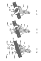
图1A是脊柱锚定装置的一个示范性的实施例的透视图;Figure 1A is a perspective view of an exemplary embodiment of a spinal anchoring device;
图1B是图1A所示的脊柱锚定装置的截面图;Figure 1B is a cross-sectional view of the spinal anchoring device shown in Figure 1A;
图2A是图1A所示的脊柱锚定装置的卡钉主体的顶视透视图;2A is a top perspective view of the staple body of the spinal anchoring device shown in FIG. 1A;
图2B是图2A所示的卡钉主体的底视透视图;Figure 2B is a bottom perspective view of the staple body shown in Figure 2A;
图3是图1A所示的脊柱锚定装置的紧固元件的透视图;3 is a perspective view of a fastening element of the spinal anchoring device shown in FIG. 1A;
图4A是形成了图1A所示的脊柱锚定装置的锁定组件的零件的垫圈的顶视透视图;4A is a top perspective view of a washer forming part of the locking assembly of the spinal anchoring device shown in FIG. 1A;
图4B是图4A所示的垫圈的底视透视图;Figure 4B is a bottom perspective view of the gasket shown in Figure 4A;
图5是形成了图1A所示的脊柱锚定装置的锁定组件的零件的锁定螺母的透视图;5 is a perspective view of a locking nut forming part of the locking assembly of the spinal anchoring device shown in FIG. 1A;
图6是扁平的柔性拴系件的一个示范性的实施例的透视图;Figure 6 is a perspective view of an exemplary embodiment of a flat flexible tether;
图7A是具有通过锁定机构与之配接的拴系件的脊柱锚定装置的另一示范性的实施例的透视图;7A is a perspective view of another exemplary embodiment of a spinal anchoring device having a tether mated thereto by a locking mechanism;
图7B是图7A所示的脊柱锚定装置的截面图;Figure 7B is a cross-sectional view of the spinal anchoring device shown in Figure 7A;
图7C是图7A所示的脊柱锚定装置的透视图,其中没有了与之配接的拴系和锁定机构;Figure 7C is a perspective view of the spinal anchoring device shown in Figure 7A without the tether and locking mechanism mated therewith;
图7D是图7C所示的脊柱锚定装置的透视图,显示了延伸通过形成在其内的通道的拴系件;Figure 7D is a perspective view of the spinal anchoring device shown in Figure 7C, showing a tether extending through a channel formed therein;
图7E是图7D所示的脊柱锚定装置的透视图,显示了锁定机构正要与之配接并且具有锁定螺母和垫圈;Figure 7E is a perspective view of the spinal anchoring device shown in Figure 7D, showing the locking mechanism just about to engage it and having a locking nut and washer;
图7F是图7E所示的脊柱锚定装置的透视图,显示了相互配接的锁定机构的锁定螺母和垫圈;Figure 7F is a perspective view of the spinal anchoring device shown in Figure 7E, showing the locking nut and washer of the interfitting locking mechanism;
图8是用于具有脊柱锚定装置的垫圈的另一实施例的透视图;Figure 8 is a perspective view of another embodiment of a washer for use with a spinal anchoring device;
图9A是具有用于接合由其延伸通过的拴系件的夹片的脊柱锚定装置的另一示范性的实施例的透视分解图;9A is a perspective exploded view of another exemplary embodiment of a spinal anchoring device having a clip for engaging a tether extending therethrough;
图9B是图9A所示的具有由其延伸通过的拴系件的脊柱锚定装置的透视装配图;9B is a perspective assembled view of the spinal anchoring device shown in FIG. 9A with a tether extending therethrough;
图9C是图9A所示的脊柱锚定装置的一部分的截面图,其中锁定机构正要与之配接;Figure 9C is a cross-sectional view of a portion of the spinal anchoring device shown in Figure 9A, with the locking mechanism about to be engaged therewith;
图9D是图9C所示的脊柱锚定装置的一部分的截面图,其中锁定机构是与之配接的;Figure 9D is a cross-sectional view of a portion of the spinal anchoring device shown in Figure 9C with the locking mechanism engaged therewith;
图10A是脊柱锚定装置的又一示范性的实施例的透视分解图,其具有由其延伸通过的拴系件并且具有两件式的锁定元件;10A is a perspective exploded view of yet another exemplary embodiment of a spinal anchoring device having a tether extending therethrough and having a two-piece locking element;
图10B是图10A所示的脊柱锚定装置的透视性部分装配图,其具有由其延伸通过的拴系件,拴系件具有形成在其内的扭转;10B is a perspective partial assembly view of the spinal anchoring device shown in FIG. 10A with a tether extending therethrough having a twist formed therein;
图10C是图10B所示的脊柱锚定装置的透视性完全装配图,其具有由其延伸通过的拴系件;Figure 10C is a perspective fully assembled view of the spinal anchoring device shown in Figure 10B with a tether extending therethrough;
图11A是显示了正要将脊柱锚定装置的卡钉植入到脊椎骨内的卡钉插入器工具的图例;11A is an illustration showing the staple inserter tool about to implant the staples of the spinal anchoring device into the vertebrae;
图11B是图11A所示的卡钉插入器工具的透视图;11B is a perspective view of the staple inserter tool shown in FIG. 11A;
图11C是图11B所示的具有与之配接的卡钉的卡钉插入器工具的远端的透视图;11C is a perspective view of the distal end of the staple inserter tool with the staple mated thereto shown in FIG. 11B;
图12A是图例,其显示了为了制备骨孔而插入通过图11A所示的卡钉插入器工具和卡钉的锥子;FIG. 12A is a diagram showing an awl inserted through the staple inserter tool and staples shown in FIG. 11A in order to prepare a bone hole;
图12B是图12A所示的锥子的透视图;Figure 12B is a perspective view of the awl shown in Figure 12A;
图12C是插入通过图12A所示的卡钉插入器工具和卡钉的图12B所示的锥子的远端的透视图;12C is a perspective view of the distal end of the awl shown in FIG. 12B inserted through the staple inserter tool and staple shown in FIG. 12A;
图13A是图例,其显示了丝锥正要插入通过植入到脊椎骨内的卡钉,以便在由锥子制备的骨孔内形成螺纹;13A is an illustration showing a screw tap being inserted through a staple implanted in a vertebra to form a thread in a bone hole prepared by the awl;
图13B是图13A所示的丝锥的透视图;Figure 13B is a perspective view of the tap shown in Figure 13A;
图14是图例,其显示了驱动器工具正要将紧固元件通过卡钉植入到骨孔内;Figure 14 is an illustration showing that the driver tool is about to implant the fastening element into the bone hole through the staple;
图15是图例,其显示了植入到两个脊椎骨内的两个脊柱锚定装置;Figure 15 is an illustration showing two spinal anchoring devices implanted in two vertebrae;
图16A是图例,其显示了相对于植入到图15所示的脊椎骨内的两个脊柱锚定装置进行定位的拴系件,并且显示了固定件插入器工具正要将紧固元件施加给脊柱锚定装置中的一个;Fig. 16 A is illustration, and it has shown the tether that is implanted in two spinal anchorage devices positioned in the vertebra shown in Fig. one of the spinal anchoring devices;
图16B是图16A所示的固定件插入器工具的透视图;Figure 16B is a perspective view of the fastener inserter tool shown in Figure 16A;
图16C是图16B所示的固定件插入器工具的远侧部的透视图,其显示了与之配接的紧固元件;Figure 16C is a perspective view of the distal portion of the fastener inserter tool shown in Figure 16B, showing the fastening elements mated therewith;
图17A是图例,其显示了使用图16A所示的固定件插入器工具施加给脊柱锚定装置的紧固元件,并且显示了插置在驱动器上的扳手;Figure 17 A is a diagram showing a fastening element applied to a spinal anchoring device using the anchor inserter tool shown in Figure 16A and showing a wrench inserted on the driver;
图17B是图例,其显示了图17A的扳手正相对于驱动器旋转,以便旋转锁定机构的锁定螺母;Figure 17B is an illustration showing the wrench of Figure 17A being rotated relative to the driver to rotate the locking nut of the locking mechanism;
图17C是图l7和图17B所示的扳手的透视图;以及Figure 17C is a perspective view of the wrench shown in Figures 17 and 17B; and
图18是图例,其显示了拴系件在植入到两个脊椎骨内的两个脊柱锚定装置之间延伸并且与之配接。Figure 18 is an illustration showing a tether extending between and mating with two spinal anchoring devices implanted in two vertebrae.
详细说明Detailed description
现在将介绍某些示范性的实施例,以便提供对在此公开的装置和方法的结构、功能、制造和使用的原理的全面理解。这些实施例的一个或多个示例显示在附图中。本领域技术人员应了解的是,在此所具体地介绍并且在附图中显示的装置和方法是非限制性的示范性的实施例,并且本发明的范围只由权利要求限定。连同一个示范性的实施例显示或介绍的特征可能与其它实施例的特征结合。这些变更和变型旨在包括在本发明的范围内。Certain exemplary embodiments will now be described in order to provide an overall understanding of the principles of the structure, function, manufacture and use of the devices and methods disclosed herein. One or more examples of these embodiments are shown in the accompanying drawings. Those skilled in the art will appreciate that the devices and methods specifically described herein and shown in the accompanying drawings are non-limiting exemplary embodiments and that the scope of the present invention is defined only by the claims. Features shown or described in connection with one exemplary embodiment may be combined with features of other embodiments. Such alterations and modifications are intended to be included within the scope of the present invention.
在一个示范性的实施例中,提供了一种低型面高度的脊柱锚定装置,用于容纳穿过其的脊柱固接(fixation)元件,诸如拴系件。使用中,若干脊柱锚定装置可植入到若干相邻脊椎骨内,而拴系件可配接到脊柱锚定装置上,以便停止在其中施加了拴系件的侧部上的脊柱生长。通过使在畸形的凸起的侧部上的脊柱停止生长,在凹入的侧部上的脊柱的随后的生长将促使畸形得到自动纠正,因此逐渐地提供了纠正同时允许患者的全面的高度得到增加。然而,该方法和装置可用于多种其它脊柱应用。作为非限制性的示例,在此公开的脊柱锚定装置和/或拴系件可用于采用随后的并合的以外科手术进行时采取的畸形纠正,如由20世纪60和70年代的医生A.F.Dwyer所教导的那样(Clin Orthop Rel Res 93,pp.191-206,1973和J Bone JointSurg 56B,pp.218-224)。另外,它们可用于以后的动力化(dynamization),以用作狭窄症(stenosis)的减压装置和/或用作椎间盘的附件而为脊椎骨的小平面卸荷。还提供了用于植入脊柱锚定装置的多种示范性的方法和工具。In an exemplary embodiment, a low profile spinal anchoring device is provided for receiving a spinal fixation element, such as a tether, therethrough. In use, several spinal anchoring devices may be implanted into several adjacent vertebrae and the tethers may be fitted to the spinal anchoring devices in order to stop the growth of the spine on the side to which the tethers are applied. By stopping the growth of the spine on the convex side of the deformity, subsequent growth of the spine on the concave side will cause the deformity to be corrected automatically, thus gradually providing correction while allowing the patient's overall height to be improved. Increase. However, the method and device can be used in a variety of other spinal applications. As a non-limiting example, the spinal anchoring devices and/or tethers disclosed herein can be used for deformity correction with subsequent incorporation surgically performed as developed by physician A.F. as taught by Dwyer (Clin Orthop Rel Res 93, pp.191-206, 1973 and J Bone Joint Surg 56B, pp.218-224). In addition, they can be used for later dynamization, as a decompression device for stenosis and/or as an attachment of an intervertebral disc to unload the facets of the spine. Exemplary methods and tools for implanting spinal anchoring devices are also provided.
图1和图1B显示了脊柱锚定装置10的一个示范性的实施例。如图所示,装置10一般包括适于承座脊柱固接元件的卡钉主体12、用于将卡钉主体12固接到骨头上的紧固元件14和用于将脊柱固接元件配接到卡钉主体12上的锁定组件。在所示的示范性的实施例中,锁定组件包括适于与卡钉主体12配接而使得脊柱固接元件设置在它们之间的垫圈16,和适于接合卡钉主体12而使垫圈16与卡钉主体12配合的锁定螺母18。然而,锁定组件可具有多种其它配置并且其可是与卡钉主体分开的或与卡钉主体配接的。An exemplary embodiment of a
卡钉主体12在图2和图2B中更详细地进行了显示,并且其可具有多种配置。在所示的示范性的实施例中,其具有基本上环形的形状,并具有上表面12s、下表面12I和穿过其形成的中心孔12o。卡钉主体12的下表面12i可包括形成在其上的一个或多个骨头接合构件26,该骨头接合构件26适于延伸进入骨头内,以便在植入卡钉12时防止卡钉12的旋转运动。图2B显示了形成在卡钉12的上的多个骨头接合构件26,该骨头接合构件26从下表面12i向远侧延伸。骨头接合构件26处于适于延伸进入骨头内的角钉(spike)的形式,然而,它们可具有多种其它形状。如进一步所示的那样,骨头接合构件26可在尺寸上变化。使用中,可用锤或其它装置来施加力给卡钉12,以便在所希望的植入部位将角钉压紧到骨头中,或者,紧固元件可用来将卡钉12驱动到骨头内,这将在下面更详细地进行论述。
卡钉主体12内的中心孔12o可适于容纳穿过其的紧固元件14,以便允许紧固元件14将卡钉主体12与骨头配合。尽管如将关于图3在下面更详细地进行论述的那样,中心孔12o的配置可根据紧固元件14的配置变化,但是在一个示范性的实施例中,中心孔12o具有在其周围形成的基本上为球形的且凹入的表面22,用于承座紧固元件14的基本上为球形的配合表面。球形的表面22允许紧固元件14是可关于卡钉主体12多轴向地移动的,从而允许紧固元件14以关于卡钉主体12的一定角度插入到骨头内。本领域技术人员将明白的是,中心孔12o可具有多种其它配置,而且卡钉主体12可包括与之整体地形成的或与之配合的紧固元件。例如,卡钉主体12可是经型锻的,使得紧固元件14与卡钉主体12整体形成同时允许紧固元件14关于卡钉主体12旋转,以便允许插入到骨头中。The central hole 12o in the
如图2和图2B所进一步显示的那样,卡钉主体12还可包括形成在上表面12s上的对立的臂20a,20b。如将在下面更详细地进行论述的那样,臂20a,20b可适于与锁定组件配接,因此臂20a,20b可包括由此形成的配合元件,用于与锁定组件的至少一部分配合。如图2和图2B中所示,每个臂20a,20b都可包括形成在其外表面上的螺纹21a,21b。螺纹21a,21b可沿着每个臂20a,20b的整个长度延伸,或者如图所示它们可仅形成在臂20a,20b的终端部分上。在本发明的一个示范性的实施例中,配合元件可具有方形螺纹图案(pattern)。每个臂20a,20b的具体配置可根据锁定机构的具体配置而变化,并且多种其它配合元件可用来接合锁定组件。As further shown in FIGS. 2 and 2B , the
使用中,卡钉主体12适于承座脊柱固接元件。因此,卡钉主体12的上表面12s可限定形成在对立的臂20a,20b之间的通道12p。通道12p可适于承座在对立的臂20a,20b之间的脊柱固接元件,使得脊柱固接元件延伸越过上表面12s和孔12o。结果,当锁定组件应用在卡钉主体12上时,脊柱固接元件可接合在锁定组件和卡钉主体12之间,以便将脊柱固接元件维持在基本上固定的位置。本领域技术人员将明白的是,通道12p可具有多种配置,并且其可是线性的或非线性的,使得其改变了方向、是曲折的、具有曲折或弯曲等。In use, the
卡钉主体12的上表面12s还可包括用以促进脊柱固接元件在锁定组件和卡钉主体12之间的接合的特征。作为非限制性的示例,上表面12s可包括形成在其上的一个或多个突起(未示出),突起适于延伸进入脊柱固接元件内,诸如拴系件,拴系件的示范性的实施例将在下面更详细地进行介绍。在其它实施例中,上表面12s可包括形成在其上的一个或多个脊或凹槽,用于接收形成在锁定组件上的一个或多个互补的凹槽或脊。图2显示了形成在卡钉主体的上表面12s的对立的侧部上并且定位在通道12p内的两个凹槽24a,24b。凹槽24a,24b适于容纳形成在锁定组件的垫圈上的互补的脊,这将关于图4和图4B更详细地进行论述。The upper surface 12s of the
如先前所述的,卡钉主体12可适于通过中心孔12o容纳紧固元件14。尽管紧固元件14可具有多种配置,但是图3显示了处于接骨螺钉的形式的一个示范性的紧固元件14,其具有头部14b和适于延伸进入骨头内的螺纹轴14。优选地,螺纹轴14a的螺纹形状适于定置在多孔的骨头内,并且在某些示范性的实施例中,螺纹轴14的表面可经过处理以便促进骨头的并置(apposition)。本领域用于促进骨头并置的已知技术包括阳极化(anodization)和涂覆包含磷酸钙、胶原、骨头生长因子等的材料。虽然紧固元件14的头部14b可根据卡钉主体12的配置在形状上和尺寸上变化,但是在所示的示范性的实施例中,头部14b包括适于坐置在卡钉主体12的孔12o内的凸缘30。凸缘30可具有大于形成在卡钉主体12内的中心孔12o的直径的直径,以便防止凸缘30穿过其。凸缘30还可包括基本上为球形的下表面(未示出),以便允许紧固元件14如先前所述的那样关于卡钉主体12多轴向地移动。As previously mentioned,
紧固元件14的头部14b还可包括从凸缘30邻近地延伸的近端延伸部32。近端延伸部32可与接骨螺钉14的轴杆14a整体地形成,并且可包括形成在其内的凹部34,用于容纳适于将紧固元件14驱动到骨头内的工具。虽然凹部34可具有任何形状和尺寸,但是在所示的实施例中其具有六边形的形状,用于容纳六边形的驱动器工具。The
使用中,当紧固元件14通过卡钉主体12的中心孔12o设置时,近端延伸部32可延伸进入通道12p内,通道12p承座脊柱固接元件,诸如柔性拴系件。这种配置是有效的,以便在拴系件中产生弯曲或纽结,从而基本上防止拴系件的滑动运动,或者另外促进拴系件在卡钉主体12和锁定组件之间的接合。本领域技术人员将明白的是,尽管显示了多轴向的接骨螺钉14,但是接骨螺钉可单轴向的或者是其可具有多种其它配置。也可使用用于将卡钉主体12附接到骨头上的其它技术。In use, when the
如关于图1和图1B所论述的那样,脊柱锚定装置10还可包括锁定组件,锁定组件适于与卡钉主体12配合,以便将诸如拴系件的脊柱固接元件维持在相对于卡钉主体12的固定位置。锁定组件的配置可进行变化,并且其可由单个部件形成或由多个部件形成。锁定组件还可与卡钉主体12分开,或者是其可与卡钉主体配接并且可在解锁配置和锁定配置之间移动。在所示的示范性的实施例中,锁定组件包括垫圈16和锁定螺母18。垫圈16适于与卡钉主体12配接,使得拴系件定位在垫圈16和卡钉主体12的上表面12s之间,而锁定螺母18可适于配合卡钉主体12的臂20a,20b,以便将垫圈16锁定到卡钉主体12上,从而在其间锁定拴系件。As discussed with respect to FIGS. 1 and 1B ,
示范性的垫圈16更详细地显示在图4和图4B中,并且如图所示,垫圈16包括一般为环形的构件35和跨过环形的构件35的压杆(strut)36。环形的构件35适于定位在卡钉主体12的对立的臂20a,20b周围,并且因此其可具有基本上对应于卡钉主体12的环形的部分的尺寸的尺寸。压杆36适于容纳在对立的臂20a,20b之间并且定位在卡钉主体12的通道12p内,以便基本上防止垫圈16关于卡钉主体12的旋转。这种配置是尤其有利的,这是因为拴系件防止了高的、有破坏性的剪切力。压杆36可适于只促进垫圈16关于卡钉主体12的定位,或者是其可适于接合设置在通道12p内的脊柱固接元件,诸如拴系件。在示范性的实施例中,如图所示,压杆36包括从环形的构件35向外延伸的对立的腿36a,36b,和在对立的腿36a,36b之间延伸的连接构件36c。这种配置允许连接构件36c远离卡钉主体12一定距离进行定位,从而允许形成在紧固元件14的头部14b上的延伸部32延伸进入通道12p内,而不紧靠压杆36的连接构件36c。然而,对立的腿36a,36b的高度可基于脊柱固接元件的尺寸进行变化,并且基于预期使用和连接构件36c是否将要接合脊柱固接元件进行变化。而且,压杆36自身可根据卡钉主体12的配置和适于设置在其内的脊柱固接元件而在形状上和尺寸上进行变化。An
如先前关于卡钉主体12所述的那样,垫圈16还可包括用以促进诸如柔性拴系件的脊柱固接元件在卡钉主体12和垫圈16之间的接合的特征。如显示了垫圈16的底部的图4B中所示,垫圈16的环形的构件35可包括形成在其上并且适于容纳在形成在如图1B中所示的卡钉主体12内的互补的凹槽24a,24b内的对立的脊38a,38b。优选地,脊38a,38b接近压杆36的腿36a,36b进行形成,使得当压杆36容纳在卡钉主体12的对立的臂20a,20b之间时,脊38a,38b与凹槽24a,24b对齐并且延伸进入凹槽24a,24b内。使用中,当柔性拴系件设置在卡钉主体12和垫圈16之间时,脊38a,38b和凹槽24a,24b将在拴系件中形成纽结,从而促进接合,使得拴系件将维持在关于装置10的基本上固定的位置。本领域技术人员将明白的是,多种其它特征可用来促进脊柱固接元件的接合。作为非限制性的示例,垫圈16可包括形成在其表面上的一个或多个突起或角钉,用于邻接或延伸到拴系件内。As previously described with respect to
如先前所指出的那样,锁定组件还可包括适于将垫圈16锁定到卡钉主体12上的锁定螺母18。更详细地显示在图5中的示范性的锁定螺母18具有一般为环形的形状。然而,锁定螺母18可具有为六边形的外表面或允许锁定螺母18通过扳手或其它驱动器工具进行接合以便旋转锁定螺母18的一些其它形状的外表面。使用中,锁定螺母18适于定位在卡钉主体12上的对立的臂20a,20b周围并且与之配合。因此,如先前所指出的那样,锁定螺母18可包括形成在其内的螺纹18a,用于与形成在卡钉主体12的臂20a,20b上的相应的螺纹21a,21b配合。在示范性的实施例中,锁定螺母18可在制造的期间型锻到垫圈16上,以将这两个整体形成但是允许螺母18在闭合机构的上紧期间关于垫圈16旋转。多种其它配合技术也可用来将锁定螺母18配合到主体上,包括搭扣配合连接、干涉配合等。As previously noted, the locking assembly may also include a locking
本领域技术人员将明白的是,锁定组件可具有多种其它配置。例如,垫圈16自身可适于与卡钉主体12配合,而不是使用锁定螺母18。垫圈16可是分开的部件,或者是其可与卡钉主体12配合并且可在打开或解锁位置和关闭或锁定位置之间移动。例如,垫圈16可通过铰链等与卡钉主体12连接。备选地,锁定螺母18可进行使用而无需垫圈16,以便将拴系件固定到卡钉主体12上。在其它实施例中,锁定螺母18可处于内调节螺钉(inner set screw)的形式,其配合卡钉主体12的腿20a,20b的内表面。Those skilled in the art will appreciate that the locking assembly may have various other configurations. For example, the
返回参见图1和图1B,使用中,装置10适于容纳和接合脊柱固接元件。尽管可使用包括柔性的和硬的固接元件的多种脊柱固接元件,但是在示范性的实施例中脊柱固接元件是柔性拴系件。图6显示了柔性拴系件50的一个示范性的实施例,并且如图所示,拴系件50基本上为扁平的或平面的。更具体地说,拴系件50可具有大于截面高度h的截面宽度w。在一个示范性的实施例中,宽度w可至少大于高度h两倍。作为非限制性的示例,宽度w可在约4mm至8mm的范围内,并且优选地约6mm,而高度h可在约0.5mm至2.5mm的范围内,并且优选地约1.5mm。备选地,拴系件可具有任意数量的不同的截面,包括方形和圆形。在一些优选的实施例中,拴系件的截面最初是方形或圆形,但是然后在闭合机构上紧时变成扁平的。Referring back to Figures 1 and IB, in use, the
拴系件50可使用多种技术制作,但是在一个示范性的实施例中其使用平编织工艺制作。例如,其它适当的工艺包括3-D编织工艺。拴系件50的性能还可进行变化,但是在示范性的实施例中拴系件具有在约1GPa至5GPa的范围内的抗拉强度,并且优选地约3GPa,而具有在约10GPa至200GPa的范围内的抗拉模量,并且优选地约100GPa。The
用来形成拴系件的材料还可进行变化,但是适当的示范性的材料包括聚合物,诸如超高分子量聚乙烯(UHMWPE)。可买到的UHMWPE纤维的示例包括Dyneema


使用中,拴系件50可在卡钉主体12植入到骨头内之后定位在卡钉主体12的通道12p内。用于将卡钉主体12驱动到骨头内的压紧工具可用来植入卡钉12。然后,紧固元件16可穿过其进行插入,以便将卡钉主体12固定到骨头上。备选地,驱动器工具可用来将紧固元件16驱动到骨头内,从而将卡钉主体12驱动到骨头内。当拴系件50定位在通道12p内时,拴系件50将在腿20a,20b之间延伸并且向上延伸在紧固元件16上的延伸部32周围。然后,垫圈14可放置在卡钉主体12的腿20a,20b周围,而锁定螺母16可螺接到腿20a,20b上,以便将垫圈16锁定到卡钉主体12上,从而将拴系件50锁定到装置10上。垫圈16上的脊38a,38b将朝着卡钉主体12上的凹槽24a,24b延伸,从而在拴系件50中产生纽结或弯曲,进一步促进了拴系件50在垫圈16和卡钉主体12之间的接合。其它用于植入脊柱锚定装置10的示范性的方法和工具将在下面更详细地进行论述。In use, the
图7A至图7F显示了脊柱锚定装置100的另一示范性的实施例。装置100类似于图1A所示的脊柱锚定装置10,并且其包括卡钉主体112、紧固元件114、垫圈116和锁定螺母118。在这个实施例中,垫圈116不包括压杆。相反地,垫圈116包括从基本上为平面的环形的主体135延伸的对立的腿136a,136b。腿136a,136b各自包括形成在其终端上并且沿着从相互的对立的方向延伸的凸缘137a,137b。凸缘137a,137b适于接合锁定螺母118,以便允许垫圈116和锁定螺母118在将锁定组件与卡钉主体12配合之前相互配合。腿136a,136b可是柔性的,以便允许锁定螺母118插在其上并且与垫圈116配合。Another exemplary embodiment of a
图7C至图7F显示了装置的装配,并且如图所示,拴系件50定位在卡钉主体112的通道内。垫圈116和锁定螺母118可如图7F中所示相互配合,而然后它们可与卡钉主体112配合。垫圈116和锁定螺母118的配合配置允许锁定螺母118关于垫圈116自由旋转,从而允许垫圈116关于卡钉主体112维持基本上固定的位置,同时锁定螺母118螺接到卡钉主体112的臂120a,120b上。这是尤其有利的,因为垫圈116的腿136a,136b将定位在卡钉主体112的臂120a,120b之间,从而防止了垫圈116关于卡钉主体112的旋转。7C-7F show the assembly of the device and the
图8显示了用于脊柱锚定装置的垫圈160的另一示范性的实施例。在这个实施例中,垫圈160具有基本上为平面的环形的构件162和跨过其延伸的基本上为平面的压杆164。垫圈160还包括形成在其上的拴系件接合突起166。使用中,卡钉主体的对立的臂,诸如图1A所示的卡钉12的臂20a,20b,适于容纳在环形的构件162内,使得压杆164在对立的臂20a,20b之间延伸。垫圈160的平面配置将促使垫圈160将拴系件50接合在卡钉主体12和垫圈160之间。结果,形成在压杆164上的突起166将邻接拴系件50并且使之变形,从而接合拴系件50而基本上防止拴系件50关于装置的运动。由于垫圈160是基本上为平面的,与卡钉主体使用的紧固元件的头部优选地不延伸进入形成在卡钉主体内的拴系件通道内,因为这种配置将促使压杆164紧靠紧固元件的头部。Figure 8 shows another exemplary embodiment of a
图9A至图9D显示了脊柱锚定装置200的又一实施例。一般而言,装置200包括类似于图1A所示的卡钉主体12、紧固元件14和锁定螺母1 8的卡钉主体212、紧固元件214和锁定螺母218。在这个实施例中,夹片216用来接合拴系件50,而不是使用垫圈16接合拴系件50。夹片216可适于设置在诸如拴系件50的脊柱固接元件周围,并且其可适于定位在卡钉主体12的通道内并且设置在卡钉主体12和锁定螺母218之间。尽管夹片216的形状和尺寸可根据与之使用的脊柱锚定装置的形状和尺寸进行变化,但是在示范性的实施例中夹片216具有基本上长形的形状和对立的臂216a,216b,臂216a,216b在其间限定了用于承座拴系件50的轨道或凹部。Still another embodiment of a
使用中,臂216a,216b可在拴系件50周围延伸,以便接合拴系件50。在另一示范性的实施例中,夹片216可由柔韧的或可变形的材料形成,以便当锁定螺母18应用在卡钉主体12上时允许夹片216在拴系件50周围变形。图9C显示了设置在拴系件50周围的夹片216,同时锁定螺母218正要与卡钉主体212配合。图9D显示了锁定螺母218螺接到卡钉主体212上,并且如图所示,夹片216通过锁定螺母218变形,使得夹片216接合拴系件50,以便防止其相对于装置200的滑动运动。在另一实施例中,夹片是用来保护拴系件同时上紧锁定螺母的可变形的管。在又一实施例中,夹片在上紧锁定螺母时不变形,从而允许拴系件在闭合机构内滑动。In use, the
图10A至图10C显示了脊柱锚定装置300的又一示范性的实施例。装置300包括类似于图1A所示的卡钉主体12和紧固元件14的卡钉主体312和紧固元件314。然而,卡钉主体312不包括形成在其上的对立的臂,但是相反地具有基本上为平面的上表面312s,而紧固元件314具有形成在其上的基本上为平面的头部314a,使得头部314与卡钉主体312的上表面312s共面或相对于其是凹进的。卡钉主体312还包括形成在其上若干配合元件,用于与锁定组件配合。尽管配合元件可具有多种配置,但是在图10A至图10C所示的示范性的实施例中卡钉主体312包括形成在其内的切口312a、312b、312c、312d,用于容纳形成在锁定机构上的键。Still another exemplary embodiment of a
如图所示,锁定机构包括第一构件和第二构件316a,316b,它们适于与卡钉主体312的上表面312s的对立的侧部配合,以便将拴系件50接合在其间。尽管未示出,但是第一构件和第二构件316a,316b可整体地形成为配合卡钉主体312的单个构件。每个构件316a,316b都可具有基本上半圆形的形状和形成在其上的配合元件,用于接合形成在卡钉主体312的上表面312s上的互补的相应的配合元件。在所示的示范性的实施例中,构件316a,316b各自包括形成在其上的两个键。仅显示出两个键317a,317b形成在第一构件316a上。每个键317a,317b都适于延伸进入形成在卡钉主体312内的相应的切口312a,312b,312c,312d内,以便通过搭扣配合或干涉配合接合卡钉主体312。As shown, the locking mechanism includes first and
使用中,拴系件50可穿过卡钉主体312进行定位,例如,在通道内,而第一构件和第二构件316a,316b然后可如图10C中所示与卡钉主体312配合,以便将拴系件50接合在其间。在示范性的实施例中,每个构件316a,316b都进行定位,使得键317a,317b定位在拴系件50的对立的侧部上,从而允许构件316a,316b的环形的部分接合拴系件50。如图10B和图10C所进一步显示的那样,拴系件50可任选地扭转,以便在两个构件316a,316b之间形成一个或多个扭转51,从而进一步防止拴系件50关于装置300的可滑动的运动。In use, the
本领域技术人员将明白的是,脊柱锚定装置可具有多种其它配置,并且其可包括在此公开的各种特征以及其它特征的组合,以便促进诸如拴系件的脊柱固接元件的接合。Those skilled in the art will appreciate that the spinal anchoring device can have a variety of other configurations and that it can include various features disclosed herein, as well as combinations of other features, to facilitate engagement of spinal fixation elements such as tethers. .
还提供了一种用于植入脊柱锚定装置的示范性的方法。尽管该方法可使用多种不同的脊柱锚定装置执行,但是该方法结合脊柱锚定装置10进行介绍。首先参见图11A,所示的卡钉插入器400用于将装置10的卡钉主体12插入到骨头内。更详细地显示在图11B中的示范性的卡钉插入器400包括一般为长形的空心轴杆402,轴杆402具有带有形成在其上的手柄404的近端,和带有形成在其上的卡钉接合构件406的远端。卡钉接合构件406适于接合卡钉主体12,以便允许主体12如图11A中所示相对于脊椎骨进行定位,,并且被驱动到脊椎骨内。尽管卡钉接合构件406的形状和尺寸可根据卡钉主体12的形状和尺寸变化,但是在示范性的实施例中卡钉接合构件包括由长形的狭槽410分开的对立的可偏转(deflectable)构件408a,408b。长形的狭槽410从装置400的最远端邻近地延伸,以便允许对立的可偏转构件408a,408b相对于彼此进行偏转。长形的狭槽410的长度可根据可偏转构件的所希望的可挠曲性变化。如图11B和图11C所进一步显示的那样,对立的可偏转构件408a,408b可包括基本上为圆柱形的远侧部,远侧部具有形成在其远侧表面内的凹部412,用于容纳卡钉主体12。在所示的实施例中,凹部412具有基本上矩形的形状,用于容纳形成在如图11C中所示的卡钉主体12上的臂20a,20b,。An exemplary method for implanting a spinal anchoring device is also provided. The method is described in connection with
使用中,卡钉主体12可通过将可偏转构件408a,408b放置在卡钉主体12上而由对立的可偏转构件408a,408b接合,从而促使构件408a,408b在臂20a,20b周围偏转,以便接合臂20a,20b。然后,可操纵卡钉插入器工具400,以便将卡钉12放置到脊椎骨内。在一个买施例中,工具400的手柄404可被压紧,以便将卡钉主体12压紧到骨头中。备选地,紧固元件14可用来将卡钉12驱动到骨头内。In use, the
一旦卡钉被植入到脊椎骨内,或至少相对于脊椎骨如所希望的那样进行了定位,则一个或多个骨头制备工具可通过插入器工具400的轴杆402插入,以便制备用于容纳紧固元件14的骨孔。作为非限制性的示例,图12显示了通过插入器工具400的空心长形的轴杆402插入的锥子420。锥子420更详细地显示在图12B中,并且如图所示,其具有一般为长形的轴杆422,轴杆422具有近端的手柄424和用于起动骨孔的远侧骨头刺入尖端426。图12C显示了插入器工具400的远端,其显示了锥子420的骨头刺入尖端426延伸通过卡钉主体12的中心孔。使用中,锥子420通过插入器工具400插入并且冲击力施加给手柄424,以便将骨头刺入尖端426驱动到骨头内。因此,施加给锥子420的驱动力也可用来将卡钉主体12驱动到骨头内。Once the staple is implanted in the vertebra, or at least positioned as desired relative to the vertebra, one or more bone preparation tools can be inserted through the
一旦骨孔在脊椎骨中通过卡钉主体12得到制备,卡钉插入器工具400和锥子420即可除去,留下植入到脊椎骨中的卡钉。然后,如图13A中所示,丝锥460可用来在骨孔内形成螺纹,从而制备用于容纳紧固元件14的骨孔。更详细地显示在图13B中的丝锥460类似于锥子420,除了其包括形成在其远端上的螺纹轴462外。备选地,丝锥可通过卡钉插入器插入,以便在骨孔内形成螺纹。Once a bone hole has been prepared in the vertebra through the
一旦使用锥子420、丝锥460和/或可能必要的任何其它的工具制备了骨孔,紧固元件14即可通过卡钉主体12插入并且进入骨孔内,以便固定地将卡钉主体12紧固到脊椎骨上。图14显示了正要使用驱动器工具480将紧固元件14插入到骨孔内。该操作可进行重复,以便将另外的脊柱锚定装置植入到一个或多个相邻脊椎骨内。图15显示了被植入到患者的脊柱的两个脊椎骨内的两个脊柱锚定装置10,10′。Once the bone hole has been prepared using the
一旦植入了所希望数量的脊柱锚定装置,诸如拴系件50的脊柱固接元件可进行定位,以便横越在该装置中的每一个之间。图16显示了在脊柱锚定装置10,10′之间延伸的拴系件50。然后,锁定组件可应用在每个脊柱锚定装置10,10′上,以便与之相对地锁定拴系件50。还如图16A所示,固定件插入器工具500可用来应用紧固元件,例如,垫圈16和锁定螺母18。更详细地显示在图16B和图16C中的示范性的插入器工具500具有一般为长形的轴杆502,轴杆502带有具有基本上为圆柱形的形状的远端,远端带有形成在其上的对立的臂504a,504b。臂504a,504b适于容纳和接合垫圈16的压杆36,从而使垫圈16以及设置在垫圈16周围的锁定螺母18与插入器工具500配合。然后,可操纵插入器工具500,以便将垫圈16和锁定螺母18定位在卡钉主体12的臂20a,20b上。Once the desired number of spinal anchoring devices are implanted, a spinal fixation element such as
如图17和图17B中所示,固定件插入器工具500还可包括扳手520,扳手520适于可滑动地设置在固定件插入器工具500上并且适于接合和旋转锁定螺母18。扳手520更详细地显示在图17C中,并且如图所示,其具有一般为长形的空心轴杆522,轴杆522带有近端的手柄524和形成在其上的远侧承窝(socket)构件526。承窝构件526包括形成在其内的承窝528并且具有对应于锁定螺母18的形状的形状。在示范性的实施例中,承窝构件526包括形成在其内的六边形的承窝528,用于与锁定螺母18的六边形的外表面配合。使用中,扳手520插到固定件插入器工具500上,直至锁定螺母18容纳在承窝528内。然后,旋转扳手520的手柄524,以便旋转锁定螺母18,从而将锁定螺母18螺接到卡钉主体12上。结果,拴系件50接合在垫圈16和卡钉主体12之间,使得其维持在基本上固定的位置。另外的锁定组件可应用在另外的脊柱锚定装置上,以便将拴系件50与之锁定。可在应用锁定组件以完成所希望的结果之前或同时给在每个锚定装置之间的拴系件50施加张力。图18显示了在两个脊柱锚定装置10,10′之间延伸的拴系件50。As shown in FIGS. 17 and 17B , the
尽管图18显示了定位脊柱的一个侧部上的单个拴系件50,但是可根据待要纠正的畸形而使用多个拴系件。如先前所指出的那样,优选地,拴系件定位在畸形的脊柱曲折的凹入的侧部上,从而停止畸形的凸起的侧部上的生长。因此,在脊柱在多个位置曲折的地方,可使用多个拴系件。例如,在第一级,三个脊柱锚定装置可放置在脊柱的曲折的凹入的侧部上的矢状平面内,而在第二级,三个另外的脊柱锚定装置可放置在脊柱的对立的侧部上,使得该三个另外的脊柱锚定装置放置在形成在脊柱内的第二弯曲的凹入的侧部上。因此,在第一级,拴系件可定位成横越在脊柱锚定装置之间,而在第二级,第二拴系件可定位成横越在脊柱的相对的侧部上的脊柱锚定装置之间。然后,张力可施加给每个拴系件并且拴系件可如先前所述的那样相对于每个脊柱锚定装置进行锁定。在每个脊椎骨之间的张力可根据所希望的纠正进行变化,这可通过张紧拴系件以外科手术进行时采取的方式完成,以便立即获得纠正,和/或通过允许脊柱的正常生长完成,以便通过使用拴系件不对称地约束生长获得纠正。一旦已经完成纠正,拴系件则可任选地被切割,以便以一个级或多个级释放张力。在一个实施例中,拴系件可以最低程度地侵入的操作进行切割。对拴系件进行切割对于防止过度纠正是尤其有利的。Although FIG. 18 shows a
如以上所指出的那样,每个固接元件的沿着患者的脊柱的位置都将根据被纠正的脊柱畸形进行变化。在其它示范性的实施例中,为了完成额面(frontal plane)内脊椎侧凸(scoliotic)畸形的纠正,可以一个后面的拴系件和一个前面的拴系件的方式在曲折的凸起的侧部上放置两个拴系件。拴系件可通过若干脊柱锚定装置与脊椎骨配合,该若干脊柱锚定装置相互接近地植入到若干相邻脊椎骨的每一个内。然后,张力可通过选择性地固定锚定装置而施加给两个前面的和后面的拴系件,以便锁定拴系件在其内。为了仅纠正额面畸形,相等的张力优选地施加给两个拴系件,而张力的程度指示了以外科手术进行时采取的方式完成了多少纠正以及留下了多少以便在不对称的生长限制期间来进行。As noted above, the position of each fixation element along the patient's spine will vary according to the spinal deformity being corrected. In other exemplary embodiments, to accomplish correction of scoliotic deformities in the frontal plane, a posterior tether and an anterior tether may be used in a tortuous convex Two tethers are placed on the sides. The tether is engageable with the vertebrae through a number of spinal anchoring devices implanted proximate to each other in each of the number of adjacent vertebrae. Tension can then be applied to both the front and rear tethers by selectively securing the anchoring means to lock the tethers therein. To correct only the frontal plane deformity, equal tension is preferably applied to both tethers, and the degree of tension dictates how much correction is done and how much is left in the manner in which the surgery is performed to allow for asymmetrical growth restriction during the period.
为了除脊椎侧凸畸形的纠正外完成矢状平面畸形的纠正,前面的和后面的拴系件优选不同地进行张紧。为了增加脊柱前凸(lordosis),后面的拴系件比前面的拴系件拉的更紧。为了增加驼背,前面的拴系件比后面的拴系件拉的更紧。类似于纠正脊椎侧凸畸形,张力的程度指示了以外科手术进行时采取的方式完成了多少纠正以及留下了多少以便在不对称的生长限制期间来进行。To accomplish correction of sagittal plane deformities in addition to correction of scoliotic deformities, the anterior and posterior tethers are preferably tensioned differently. To increase lordosis, the rear tether is pulled tighter than the front tether. To increase hump, the front tethers are pulled tighter than the rear tethers. Similar to correcting a scoliotic deformity, the degree of tension dictates how much correction is done in the manner in which the surgery is performed and how much is left for periods of asymmetric growth restriction.
在某些示范性的应用中,在此介绍的植入物和器械用来用于最低程度地侵入的外科操作;因此,大小是这样的,使得它们可通过具有大约5至30mm的内直径的入口插入,该内直径更优选地为15至20mm。这在植入物用来纠正整容畸形时是尤其重要的,其中长的切口将否定纠正的正面的整容效果。In certain exemplary applications, the implants and instruments described herein are used for minimally invasive surgical procedures; therefore, the size is such that they can pass through a The inlet is inserted, the inner diameter is more preferably 15 to 20mm. This is especially important when implants are used to correct cosmetic deformities where a long incision would negate the positive cosmetic effect of the correction.
基于上述实施例,本领域普通技术人员将理解本发明的进一步特征和优势。因此,本发明不是要被所已经具体显示和介绍的那些限制,除了如由所附的权利要求指出的那样。在此引用的所有公开物和参考文献通过引用整体地且明白地结合于本文中。Based on the above-described embodiments, those of ordinary skill in the art will appreciate further features and advantages of the present invention. Accordingly, the invention is not to be limited by what has been particularly shown and described, except as indicated by the appended claims. All publications and references cited herein are hereby incorporated by reference in their entirety and expressly.
Claims (39)
Applications Claiming Priority (7)
| Application Number | Priority Date | Filing Date | Title |
|---|---|---|---|
| US10/907,231 US8273086B2 (en) | 2005-03-24 | 2005-03-24 | Low profile spinal tethering devices |
| US10/907,231 | 2005-03-24 | ||
| US10/907,232 | 2005-03-24 | ||
| US10/907,233 US8123749B2 (en) | 2005-03-24 | 2005-03-24 | Low profile spinal tethering systems |
| US10/907,233 | 2005-03-24 | ||
| US10/907,232 US7909826B2 (en) | 2005-03-24 | 2005-03-24 | Low profile spinal tethering methods |
| PCT/US2006/002068 WO2006104538A1 (en) | 2005-03-24 | 2006-01-20 | Low profile spinal tethering devices |
Publications (2)
| Publication Number | Publication Date |
|---|---|
| CN101146486A CN101146486A (en) | 2008-03-19 |
| CN101146486B true CN101146486B (en) | 2012-03-21 |
Family
ID=37053675
Family Applications (1)
| Application Number | Title | Priority Date | Filing Date |
|---|---|---|---|
| CN2006800093739A Expired - Lifetime CN101146486B (en) | 2005-03-24 | 2006-01-20 | Low profile spinal tethering devices |
Country Status (10)
| Country | Link |
|---|---|
| US (8) | US8273086B2 (en) |
| EP (2) | EP2404563B1 (en) |
| JP (1) | JP4970423B2 (en) |
| CN (1) | CN101146486B (en) |
| AT (1) | ATE548980T1 (en) |
| AU (1) | AU2006229616B2 (en) |
| BR (1) | BRPI0609720B8 (en) |
| CA (1) | CA2602499C (en) |
| MX (1) | MX2007011782A (en) |
| WO (1) | WO2006104538A1 (en) |
Cited By (1)
| Publication number | Priority date | Publication date | Assignee | Title |
|---|---|---|---|---|
| TWI613991B (en) * | 2012-08-15 | 2018-02-11 | 星瑟斯有限公司 | Drug eluting surgical screw |
Families Citing this family (234)
| Publication number | Priority date | Publication date | Assignee | Title |
|---|---|---|---|---|
| US7833250B2 (en) | 2004-11-10 | 2010-11-16 | Jackson Roger P | Polyaxial bone screw with helically wound capture connection |
| US7862587B2 (en) | 2004-02-27 | 2011-01-04 | Jackson Roger P | Dynamic stabilization assemblies, tool set and method |
| US10258382B2 (en) | 2007-01-18 | 2019-04-16 | Roger P. Jackson | Rod-cord dynamic connection assemblies with slidable bone anchor attachment members along the cord |
| US8292926B2 (en) | 2005-09-30 | 2012-10-23 | Jackson Roger P | Dynamic stabilization connecting member with elastic core and outer sleeve |
| US10729469B2 (en) | 2006-01-09 | 2020-08-04 | Roger P. Jackson | Flexible spinal stabilization assembly with spacer having off-axis core member |
| US8353932B2 (en) | 2005-09-30 | 2013-01-15 | Jackson Roger P | Polyaxial bone anchor assembly with one-piece closure, pressure insert and plastic elongate member |
| US8876868B2 (en) | 2002-09-06 | 2014-11-04 | Roger P. Jackson | Helical guide and advancement flange with radially loaded lip |
| US7621918B2 (en) | 2004-11-23 | 2009-11-24 | Jackson Roger P | Spinal fixation tool set and method |
| US7377923B2 (en) | 2003-05-22 | 2008-05-27 | Alphatec Spine, Inc. | Variable angle spinal screw assembly |
| US8366753B2 (en) | 2003-06-18 | 2013-02-05 | Jackson Roger P | Polyaxial bone screw assembly with fixed retaining structure |
| US8936623B2 (en) | 2003-06-18 | 2015-01-20 | Roger P. Jackson | Polyaxial bone screw assembly |
| US7766915B2 (en) | 2004-02-27 | 2010-08-03 | Jackson Roger P | Dynamic fixation assemblies with inner core and outer coil-like member |
| US7776067B2 (en) | 2005-05-27 | 2010-08-17 | Jackson Roger P | Polyaxial bone screw with shank articulation pressure insert and method |
| US7967850B2 (en) | 2003-06-18 | 2011-06-28 | Jackson Roger P | Polyaxial bone anchor with helical capture connection, insert and dual locking assembly |
| US7527638B2 (en) | 2003-12-16 | 2009-05-05 | Depuy Spine, Inc. | Methods and devices for minimally invasive spinal fixation element placement |
| US11419642B2 (en) | 2003-12-16 | 2022-08-23 | Medos International Sarl | Percutaneous access devices and bone anchor assemblies |
| US7179261B2 (en) | 2003-12-16 | 2007-02-20 | Depuy Spine, Inc. | Percutaneous access devices and bone anchor assemblies |
| US8353933B2 (en) * | 2007-04-17 | 2013-01-15 | Gmedelaware 2 Llc | Facet joint replacement |
| US9050148B2 (en) | 2004-02-27 | 2015-06-09 | Roger P. Jackson | Spinal fixation tool attachment structure |
| CA2701522C (en) | 2004-02-27 | 2012-05-15 | Roger P. Jackson | Orthopedic implant rod reduction tool set and method |
| US8152810B2 (en) | 2004-11-23 | 2012-04-10 | Jackson Roger P | Spinal fixation tool set and method |
| US11241261B2 (en) | 2005-09-30 | 2022-02-08 | Roger P Jackson | Apparatus and method for soft spinal stabilization using a tensionable cord and releasable end structure |
| US7160300B2 (en) | 2004-02-27 | 2007-01-09 | Jackson Roger P | Orthopedic implant rod reduction tool set and method |
| US8114158B2 (en) | 2004-08-03 | 2012-02-14 | Kspine, Inc. | Facet device and method |
| US8414648B2 (en) | 2004-08-09 | 2013-04-09 | Si-Bone Inc. | Apparatus, systems, and methods for achieving trans-iliac lumbar fusion |
| US20060036251A1 (en) | 2004-08-09 | 2006-02-16 | Reiley Mark A | Systems and methods for the fixation or fusion of bone |
| US20070156241A1 (en) | 2004-08-09 | 2007-07-05 | Reiley Mark A | Systems and methods for the fixation or fusion of bone |
| US8444693B2 (en) | 2004-08-09 | 2013-05-21 | Si-Bone Inc. | Apparatus, systems, and methods for achieving lumbar facet fusion |
| US8470004B2 (en) | 2004-08-09 | 2013-06-25 | Si-Bone Inc. | Apparatus, systems, and methods for stabilizing a spondylolisthesis |
| US9662158B2 (en) * | 2004-08-09 | 2017-05-30 | Si-Bone Inc. | Systems and methods for the fixation or fusion of bone at or near a sacroiliac joint |
| US8986348B2 (en) | 2004-08-09 | 2015-03-24 | Si-Bone Inc. | Systems and methods for the fusion of the sacral-iliac joint |
| US8425570B2 (en) | 2004-08-09 | 2013-04-23 | Si-Bone Inc. | Apparatus, systems, and methods for achieving anterior lumbar interbody fusion |
| US20180228621A1 (en) | 2004-08-09 | 2018-08-16 | Mark A. Reiley | Apparatus, systems, and methods for the fixation or fusion of bone |
| US9949843B2 (en) | 2004-08-09 | 2018-04-24 | Si-Bone Inc. | Apparatus, systems, and methods for the fixation or fusion of bone |
| US7651502B2 (en) | 2004-09-24 | 2010-01-26 | Jackson Roger P | Spinal fixation tool set and method for rod reduction and fastener insertion |
| US8926672B2 (en) | 2004-11-10 | 2015-01-06 | Roger P. Jackson | Splay control closure for open bone anchor |
| US9168069B2 (en) | 2009-06-15 | 2015-10-27 | Roger P. Jackson | Polyaxial bone anchor with pop-on shank and winged insert with lower skirt for engaging a friction fit retainer |
| US9918745B2 (en) | 2009-06-15 | 2018-03-20 | Roger P. Jackson | Polyaxial bone anchor with pop-on shank and winged insert with friction fit compressive collet |
| US9216041B2 (en) | 2009-06-15 | 2015-12-22 | Roger P. Jackson | Spinal connecting members with tensioned cords and rigid sleeves for engaging compression inserts |
| US9393047B2 (en) | 2009-06-15 | 2016-07-19 | Roger P. Jackson | Polyaxial bone anchor with pop-on shank and friction fit retainer with low profile edge lock |
| US8444681B2 (en) | 2009-06-15 | 2013-05-21 | Roger P. Jackson | Polyaxial bone anchor with pop-on shank, friction fit retainer and winged insert |
| US8172855B2 (en) | 2004-11-24 | 2012-05-08 | Abdou M S | Devices and methods for inter-vertebral orthopedic device placement |
| US8273086B2 (en) | 2005-03-24 | 2012-09-25 | Depuy Spine, Inc. | Low profile spinal tethering devices |
| US11903849B2 (en) | 2005-04-12 | 2024-02-20 | Moskowitz Family Llc | Intervertebral implant and tool assembly |
| US7942903B2 (en) | 2005-04-12 | 2011-05-17 | Moskowitz Ahmnon D | Bi-directional fixating transvertebral body screws and posterior cervical and lumbar interarticulating joint calibrated stapling devices for spinal fusion |
| US8070749B2 (en) * | 2005-05-12 | 2011-12-06 | Stern Joseph D | Revisable anterior cervical plating system |
| US20060271052A1 (en) * | 2005-05-12 | 2006-11-30 | Stern Joseph D | Revisable anterior cervical plating system |
| US8105368B2 (en) | 2005-09-30 | 2012-01-31 | Jackson Roger P | Dynamic stabilization connecting member with slitted core and outer sleeve |
| US7704271B2 (en) | 2005-12-19 | 2010-04-27 | Abdou M Samy | Devices and methods for inter-vertebral orthopedic device placement |
| US7722652B2 (en) | 2006-01-27 | 2010-05-25 | Warsaw Orthopedic, Inc. | Pivoting joints for spinal implants including designed resistance to motion and methods of use |
| US8057519B2 (en) | 2006-01-27 | 2011-11-15 | Warsaw Orthopedic, Inc. | Multi-axial screw assembly |
| US7833252B2 (en) | 2006-01-27 | 2010-11-16 | Warsaw Orthopedic, Inc. | Pivoting joints for spinal implants including designed resistance to motion and methods of use |
| US7494265B2 (en) | 2006-03-01 | 2009-02-24 | Entegris, Inc. | System and method for controlled mixing of fluids via temperature |
| EP2032053A2 (en) * | 2006-06-07 | 2009-03-11 | Disc Motion Technologies Inc. | Pedicle screw system |
| US8021369B2 (en) * | 2006-06-12 | 2011-09-20 | Howmedica Osteonics Corp. | Navigated femoral neck resection guide and method |
| US7988711B2 (en) | 2006-09-21 | 2011-08-02 | Warsaw Orthopedic, Inc. | Low profile vertebral stabilization systems and methods |
| US8361130B2 (en) * | 2006-10-06 | 2013-01-29 | Depuy Spine, Inc. | Bone screw fixation |
| AU2007332794C1 (en) | 2006-12-08 | 2012-01-12 | Roger P. Jackson | Tool system for dynamic spinal implants |
| US8636783B2 (en) | 2006-12-29 | 2014-01-28 | Zimmer Spine, Inc. | Spinal stabilization systems and methods |
| US8366745B2 (en) | 2007-05-01 | 2013-02-05 | Jackson Roger P | Dynamic stabilization assembly having pre-compressed spacers with differential displacements |
| US8475498B2 (en) | 2007-01-18 | 2013-07-02 | Roger P. Jackson | Dynamic stabilization connecting member with cord connection |
| US8133261B2 (en) * | 2007-02-26 | 2012-03-13 | Depuy Spine, Inc. | Intra-facet fixation device and method of use |
| US20080234753A1 (en) * | 2007-03-19 | 2008-09-25 | Warsaw Orthopedic, Inc. | Spinal Stabilization Systems |
| WO2008118295A2 (en) * | 2007-03-26 | 2008-10-02 | Laszlo Garamszegi | Bottom-loading pedicle screw assembly |
| US8197513B2 (en) * | 2007-04-13 | 2012-06-12 | Depuy Spine, Inc. | Facet fixation and fusion wedge and method of use |
| US8043334B2 (en) | 2007-04-13 | 2011-10-25 | Depuy Spine, Inc. | Articulating facet fusion screw |
| US8894685B2 (en) * | 2007-04-13 | 2014-11-25 | DePuy Synthes Products, LLC | Facet fixation and fusion screw and washer assembly and method of use |
| US20080269805A1 (en) | 2007-04-25 | 2008-10-30 | Warsaw Orthopedic, Inc. | Methods for correcting spinal deformities |
| US10383660B2 (en) | 2007-05-01 | 2019-08-20 | Roger P. Jackson | Soft stabilization assemblies with pretensioned cords |
| US9039711B2 (en) | 2007-08-21 | 2015-05-26 | DePuy Synthes Products, Inc. | Instruments and methods for tensioning a spinal tether |
| US12539219B2 (en) | 2007-08-21 | 2026-02-03 | Moskowitz Family Llc | Intervertebral implant and tool assembly |
| US9101410B1 (en) | 2007-10-24 | 2015-08-11 | Robert E. Urrea | Facet joint fusion device and method for using same |
| WO2009136009A1 (en) * | 2008-05-05 | 2009-11-12 | Maurice Bertholet | Intervertebral prosthetic device |
| US8292930B2 (en) * | 2008-05-06 | 2012-10-23 | Warsaw Orthopedic, Inc. | Tethering devices and methods to treat a spinal deformity |
| AU2009246785B2 (en) | 2008-05-14 | 2015-05-28 | Smith & Nephew, Inc. | Arthroscopic biceps tenodesis repair |
| US8206421B2 (en) * | 2008-05-15 | 2012-06-26 | Warsaw Othropedic, Inc. | Methods and devices for insertion of tethers through subcutaneous screw heads |
| CA2739997C (en) | 2008-08-01 | 2013-08-13 | Roger P. Jackson | Longitudinal connecting member with sleeved tensioned cords |
| US20100094358A1 (en) * | 2008-10-10 | 2010-04-15 | K2M, Inc. | Spinal staple |
| FR2937531B1 (en) * | 2008-10-23 | 2016-01-29 | Lotfi Miladi | SPINAL OSTEOSYNTHESIS SYSTEM |
| US8377101B2 (en) * | 2008-11-05 | 2013-02-19 | K2M, Inc. | Multi-planar taper lock screw with increased rod friction |
| US8828058B2 (en) | 2008-11-11 | 2014-09-09 | Kspine, Inc. | Growth directed vertebral fixation system with distractible connector(s) and apical control |
| JP5904794B2 (en) | 2008-12-09 | 2016-04-20 | スミス アンド ネフュー インコーポレーテッドSmith & Nephew,Inc. | Tissue repair assembly |
| US8858606B2 (en) | 2008-12-09 | 2014-10-14 | Smith & Nephew, Inc. | Tissue repair assembly |
| US8357183B2 (en) | 2009-03-26 | 2013-01-22 | Kspine, Inc. | Semi-constrained anchoring system |
| US11229457B2 (en) | 2009-06-15 | 2022-01-25 | Roger P. Jackson | Pivotal bone anchor assembly with insert tool deployment |
| US8998959B2 (en) | 2009-06-15 | 2015-04-07 | Roger P Jackson | Polyaxial bone anchors with pop-on shank, fully constrained friction fit retainer and lock and release insert |
| US8529609B2 (en) * | 2009-12-01 | 2013-09-10 | Osteomed Llc | Polyaxial facet fixation screw system |
| US8876867B2 (en) | 2009-06-24 | 2014-11-04 | Zimmer Spine, Inc. | Spinal correction tensioning system |
| US9168071B2 (en) | 2009-09-15 | 2015-10-27 | K2M, Inc. | Growth modulation system |
| EP2485654B1 (en) | 2009-10-05 | 2021-05-05 | Jackson P. Roger | Polyaxial bone anchor with non-pivotable retainer and pop-on shank, some with friction fit |
| US20120272816A1 (en) * | 2009-10-22 | 2012-11-01 | Alfresa Pharma Corporation | Braided flat cable constituted of ultrahigh-molecular polyethylene fibers |
| US8613746B2 (en) * | 2009-10-27 | 2013-12-24 | DePuy Synthes Products, LLC. | Preparatory reamers for orthopedic implants |
| US8211151B2 (en) * | 2009-10-30 | 2012-07-03 | Warsaw Orthopedic | Devices and methods for dynamic spinal stabilization and correction of spinal deformities |
| US9078701B2 (en) * | 2009-11-09 | 2015-07-14 | Centinel Spine, Inc. | System and method for stabilizing a posterior fusion over motion segments |
| US9078707B2 (en) | 2009-12-01 | 2015-07-14 | Osteomed Llc | Polyaxial facet fixation screw system with cannula inserter |
| US8764806B2 (en) | 2009-12-07 | 2014-07-01 | Samy Abdou | Devices and methods for minimally invasive spinal stabilization and instrumentation |
| US8690924B2 (en) * | 2010-02-04 | 2014-04-08 | Spinefrontier Inc | Spinal screw assembly |
| CA2797790A1 (en) * | 2010-05-13 | 2011-11-17 | Synthes Usa, Llc | Bone screw assembly and instruments for implantation of the same |
| JP6081353B2 (en) * | 2010-06-03 | 2017-02-15 | スミス アンド ネフュー インコーポレイテッド | Orthopedic implant |
| US20110313466A1 (en) * | 2010-06-17 | 2011-12-22 | Butler Michael S | Spinal Facet Bone Screw System |
| WO2011163402A1 (en) | 2010-06-22 | 2011-12-29 | Osteomed, Lp | Polyaxial facet fixation screw system with fixation augmentation |
| US9044277B2 (en) | 2010-07-12 | 2015-06-02 | DePuy Synthes Products, Inc. | Pedicular facet fusion screw with plate |
| EP2595560A1 (en) | 2010-07-23 | 2013-05-29 | Ecole Polytechnique Federale De Lausanne (EPFL) EPFL-TTO | Adjustable fixation system for neurosurgical devices |
| US20120029567A1 (en) * | 2010-07-30 | 2012-02-02 | Warsaw Orthopedic, Inc. | Anchoring mechanism |
| BR112013005465A2 (en) | 2010-09-08 | 2019-09-24 | P Jackson Roger | connecting element in a medical implant assembly having at least two bone attachment structures cooperating with a dynamic longitudinal connecting element |
| WO2012048131A2 (en) * | 2010-10-06 | 2012-04-12 | Simpirica Spine, Inc. | Device and accessories for limiting flexion |
| US8992579B1 (en) | 2011-03-08 | 2015-03-31 | Nuvasive, Inc. | Lateral fixation constructs and related methods |
| US8870929B2 (en) | 2011-04-13 | 2014-10-28 | Polyvalor, Limited Partnership Valorisation HSJ, Limited Partnership | Surgical devices for the correction of spinal deformities |
| WO2012158208A2 (en) * | 2011-05-08 | 2012-11-22 | Spinal Ventures, Llc | Implant and fastener fixation devices and delivery instrumentation |
| CA2838047A1 (en) | 2011-06-03 | 2012-12-06 | Kspine, Inc. | Spinal correction system actuators |
| EP3205299B1 (en) * | 2011-06-29 | 2019-10-30 | Biomet Microfixation, Llc | Locking mechanism to secure ends of an implantable fabric |
| FR2977138B1 (en) * | 2011-06-30 | 2014-02-28 | Implanet | DEVICE FOR FIXING VERTEBRAL |
| US11026722B2 (en) | 2011-09-14 | 2021-06-08 | Orthopediatrics Corp. | Orthopedic tethered implants and system |
| US9173685B2 (en) | 2011-09-14 | 2015-11-03 | Band-Lok, Llc | Tether clamp and implantation system |
| US8845728B1 (en) | 2011-09-23 | 2014-09-30 | Samy Abdou | Spinal fixation devices and methods of use |
| EP2589351B1 (en) * | 2011-11-01 | 2021-11-24 | Synergy Disc Replacement Inc. | Facet fixation systems |
| US9119678B2 (en) * | 2011-11-01 | 2015-09-01 | Synergy Disc Replacement Inc. | Facet fixation systems |
| US9414865B2 (en) * | 2011-11-01 | 2016-08-16 | Synergy Disc Replacement Inc. | Joint and bone fixation |
| WO2014172632A2 (en) | 2011-11-16 | 2014-10-23 | Kspine, Inc. | Spinal correction and secondary stabilization |
| US8920472B2 (en) | 2011-11-16 | 2014-12-30 | Kspine, Inc. | Spinal correction and secondary stabilization |
| US9468469B2 (en) | 2011-11-16 | 2016-10-18 | K2M, Inc. | Transverse coupler adjuster spinal correction systems and methods |
| US9468468B2 (en) | 2011-11-16 | 2016-10-18 | K2M, Inc. | Transverse connector for spinal stabilization system |
| US9451987B2 (en) | 2011-11-16 | 2016-09-27 | K2M, Inc. | System and method for spinal correction |
| US8961570B2 (en) | 2012-01-24 | 2015-02-24 | Warsaw Othopedic, Inc. | Spinal correction system and method |
| WO2013112477A1 (en) * | 2012-01-24 | 2013-08-01 | Synthes Usa, Llc | Compression screw system |
| US20130226240A1 (en) | 2012-02-22 | 2013-08-29 | Samy Abdou | Spinous process fixation devices and methods of use |
| US9060815B1 (en) | 2012-03-08 | 2015-06-23 | Nuvasive, Inc. | Systems and methods for performing spine surgery |
| KR20140147834A (en) | 2012-03-09 | 2014-12-30 | 에스아이-본 인코포레이티드 | Integrated implant |
| WO2013134682A1 (en) | 2012-03-09 | 2013-09-12 | Si-Bone Inc. | Artificial si joint |
| WO2013134778A1 (en) * | 2012-03-09 | 2013-09-12 | Si-Bone Inc. | Impactor |
| US10363140B2 (en) | 2012-03-09 | 2019-07-30 | Si-Bone Inc. | Systems, device, and methods for joint fusion |
| JP6629068B2 (en) | 2012-05-04 | 2020-01-15 | エスアイ−ボーン・インコーポレイテッドSi−Bone, Inc. | Fenestrated implant |
| EP3677204B1 (en) | 2012-05-11 | 2024-12-18 | OrthoPediatrics Corp. | Surgical connectors and instrumentation |
| WO2013190431A1 (en) * | 2012-06-18 | 2013-12-27 | Hodgson Bruce Francis | Method and apparatus for the treatment of scoliosis |
| US10327818B2 (en) | 2012-06-18 | 2019-06-25 | Bruce Francis Hodgson | Method and apparatus for the treatment of scoliosis |
| US9151316B2 (en) | 2012-07-25 | 2015-10-06 | Alan R. Smith | Fastener with unidirectional latch |
| US9198767B2 (en) | 2012-08-28 | 2015-12-01 | Samy Abdou | Devices and methods for spinal stabilization and instrumentation |
| CN103654934B (en) * | 2012-08-30 | 2016-03-30 | 上海微创骨科医疗科技有限公司 | For blade plate combined locking screw and comprise its bone plate system |
| US9757160B2 (en) | 2012-09-28 | 2017-09-12 | Globus Medical, Inc. | Device and method for treatment of spinal deformity |
| US9101426B2 (en) | 2012-10-11 | 2015-08-11 | Stryker Trauma Sa | Cable plug |
| US9320617B2 (en) | 2012-10-22 | 2016-04-26 | Cogent Spine, LLC | Devices and methods for spinal stabilization and instrumentation |
| US9549666B2 (en) | 2012-11-10 | 2017-01-24 | Curvo Medical, Inc. | Coaxial micro-endoscope |
| US9233225B2 (en) | 2012-11-10 | 2016-01-12 | Curvo Medical, Inc. | Coaxial bi-directional catheter |
| US8911478B2 (en) | 2012-11-21 | 2014-12-16 | Roger P. Jackson | Splay control closure for open bone anchor |
| US20140148854A1 (en) | 2012-11-28 | 2014-05-29 | Zimmer Spine, Inc. | Vertebral fixation system |
| US20150313659A1 (en) * | 2012-12-07 | 2015-11-05 | Kagoshima University | Fastening force auxiliary device for screw and screw with fastening force auxiliary device |
| CN103860246B (en) * | 2012-12-12 | 2016-12-21 | 上海微创骨科医疗科技有限公司 | Pedicle screw and Thoracolumbar disk Anterior fixation system |
| US10058354B2 (en) | 2013-01-28 | 2018-08-28 | Roger P. Jackson | Pivotal bone anchor assembly with frictional shank head seating surfaces |
| US8852239B2 (en) | 2013-02-15 | 2014-10-07 | Roger P Jackson | Sagittal angle screw with integral shank and receiver |
| EP2777569B1 (en) | 2013-03-11 | 2019-12-25 | K2M, Inc. | Flexible fastening system |
| US20140277155A1 (en) | 2013-03-14 | 2014-09-18 | K2M, Inc. | Taper lock hook |
| US9707096B2 (en) | 2013-03-14 | 2017-07-18 | K2M, Inc. | Spinal fixation device |
| US10292832B2 (en) | 2013-03-14 | 2019-05-21 | Ohio State Innovation Foundation | Spinal fixation device |
| US9936983B2 (en) | 2013-03-15 | 2018-04-10 | Si-Bone Inc. | Implants for spinal fixation or fusion |
| ES2745673T3 (en) | 2013-03-15 | 2020-03-03 | Shriners Hospitals Children | Techniques for spinal surgery |
| CA2923088A1 (en) * | 2013-09-05 | 2015-03-12 | Ceramtec Gmbh | Screw with an elliptical longitudinal and/or cross section |
| US9468471B2 (en) | 2013-09-17 | 2016-10-18 | K2M, Inc. | Transverse coupler adjuster spinal correction systems and methods |
| US9517089B1 (en) | 2013-10-08 | 2016-12-13 | Nuvasive, Inc. | Bone anchor with offset rod connector |
| WO2015057866A1 (en) | 2013-10-15 | 2015-04-23 | Si-Bone Inc. | Implant placement |
| US11147688B2 (en) | 2013-10-15 | 2021-10-19 | Si-Bone Inc. | Implant placement |
| US9566092B2 (en) | 2013-10-29 | 2017-02-14 | Roger P. Jackson | Cervical bone anchor with collet retainer and outer locking sleeve |
| KR101796509B1 (en) | 2013-11-06 | 2017-12-01 | 와트 퓨얼 셀 코퍼레이션 | Liquid fuel cpox reformers and methods of cpox reforming |
| AU2014346836B2 (en) | 2013-11-06 | 2017-12-14 | WATT Fuel Cell Corp | Liquid fuel CPOX reformer and fuel cell systems, and methods of producing electricity |
| US9451993B2 (en) | 2014-01-09 | 2016-09-27 | Roger P. Jackson | Bi-radial pop-on cervical bone anchor |
| ES2804126T3 (en) | 2014-02-24 | 2021-02-03 | Univ Curtin Tech | Bra |
| US20150265303A1 (en) * | 2014-03-20 | 2015-09-24 | Warsaw Orthopedic, Inc. | Spinal correction release system and method |
| JP6654147B2 (en) * | 2014-05-15 | 2020-02-26 | スミス アンド ネフュー インコーポレイテッド | Tissue graft fixation with tension adjustment |
| US10064658B2 (en) | 2014-06-04 | 2018-09-04 | Roger P. Jackson | Polyaxial bone anchor with insert guides |
| US9597119B2 (en) | 2014-06-04 | 2017-03-21 | Roger P. Jackson | Polyaxial bone anchor with polymer sleeve |
| US10499968B2 (en) | 2014-08-08 | 2019-12-10 | Stryker European Holdings I, Llc | Cable plugs for bone plates |
| JP6542362B2 (en) | 2014-09-18 | 2019-07-10 | エスアイ−ボーン・インコーポレイテッドSi−Bone, Inc. | Matrix implant |
| WO2016044731A1 (en) | 2014-09-18 | 2016-03-24 | Si-Bone Inc. | Implants for bone fixation or fusion |
| US10076374B2 (en) | 2014-10-23 | 2018-09-18 | Medos International Sárl | Biceps tenodesis delivery tools |
| US10034742B2 (en) | 2014-10-23 | 2018-07-31 | Medos International Sarl | Biceps tenodesis implants and delivery tools |
| US10856966B2 (en) | 2014-10-23 | 2020-12-08 | Medos International Sarl | Biceps tenodesis implants and delivery tools |
| US10751161B2 (en) | 2014-10-23 | 2020-08-25 | Medos International Sárl | Biceps tenodesis anchor implants |
| US10729419B2 (en) | 2014-10-23 | 2020-08-04 | Medos International Sarl | Biceps tenodesis implants and delivery tools |
| TW201617039A (en) * | 2014-11-06 | 2016-05-16 | 愛派司生技股份有限公司 | A bone screw for cable penetration |
| CN107530108A (en) * | 2014-12-03 | 2018-01-02 | S.马利 理查德 | Bone implant with tether |
| EP3095400B1 (en) * | 2015-02-12 | 2021-12-15 | K2M, Inc. | Spinal fixation construct |
| US12490978B2 (en) | 2015-02-24 | 2025-12-09 | Orthovestments, Llc | Orthopedic bone staple with polyaxial compression capability |
| USD851250S1 (en) * | 2015-11-19 | 2019-06-11 | Orthovestments, Llc | Bone staple |
| US10376206B2 (en) | 2015-04-01 | 2019-08-13 | Si-Bone Inc. | Neuromonitoring systems and methods for bone fixation or fusion procedures |
| FR3034646A1 (en) * | 2015-04-13 | 2016-10-14 | Univ Grenoble 1 | MINIMALLY INVASIVE SYSTEM FOR DYNAMIC CORRECTION OF SPINAL DEFORMATION |
| FR3034978B1 (en) * | 2015-04-17 | 2017-04-07 | Implanet | SYSTEM, PART AND METHOD FOR VERTEBRAL ANCHORING. |
| US9693856B2 (en) | 2015-04-22 | 2017-07-04 | DePuy Synthes Products, LLC | Biceps repair device |
| EP3285667B1 (en) | 2015-04-24 | 2022-12-14 | K2M, Inc. | Tethering screw system |
| US9795421B2 (en) | 2015-07-07 | 2017-10-24 | K2M, Inc. | Spinal construct with flexible member |
| WO2017049268A1 (en) | 2015-09-18 | 2017-03-23 | K2M, Inc. | Corpectomy device and method of use thereof |
| US10857003B1 (en) | 2015-10-14 | 2020-12-08 | Samy Abdou | Devices and methods for vertebral stabilization |
| EP3429481B1 (en) | 2016-03-18 | 2023-06-28 | Curtin University | An expandable fastener for orthopaedic applications |
| US10231824B2 (en) | 2016-04-08 | 2019-03-19 | Medos International Sárl | Tenodesis anchoring systems and tools |
| US10231823B2 (en) | 2016-04-08 | 2019-03-19 | Medos International Sarl | Tenodesis implants and tools |
| CN105852951A (en) * | 2016-05-04 | 2016-08-17 | 高嘉锴 | Hollow screw for restoring damaged ligaments or muscle tendons |
| JP7177494B2 (en) * | 2016-05-19 | 2022-11-24 | アークタス サージカル インク | spinal curvature adjustment system |
| US12262917B2 (en) | 2016-05-19 | 2025-04-01 | Auctus Surgical, Inc. | Spinal curvature modulation systems and methods |
| US20180000522A1 (en) * | 2016-06-30 | 2018-01-04 | Linares Medical Devices, Llc | Vertebral scaffold for supporting a rear of a spinal column along opposite extending rows of lateral processes |
| US10413330B2 (en) * | 2016-08-09 | 2019-09-17 | Warsaw Orthopedic, Inc. | Spinal implant system and method |
| EP3525699B1 (en) | 2016-10-11 | 2023-07-26 | K2M, Inc. | Spinal implant |
| US10744000B1 (en) | 2016-10-25 | 2020-08-18 | Samy Abdou | Devices and methods for vertebral bone realignment |
| US10973648B1 (en) | 2016-10-25 | 2021-04-13 | Samy Abdou | Devices and methods for vertebral bone realignment |
| JP6871769B2 (en) | 2017-03-16 | 2021-05-12 | オリンパステルモバイオマテリアル株式会社 | Vertebrae spacer and vertebral arch spacer kit |
| US10667845B2 (en) | 2017-07-19 | 2020-06-02 | Mayo Foundation For Medical Education And Research | Vertebral tethering |
| US10905474B2 (en) | 2017-08-29 | 2021-02-02 | Zimmer Biomet Spine, Inc. | Surgical cord tensioning devices, systems, and methods |
| US10939941B2 (en) | 2017-08-29 | 2021-03-09 | Zimmer Biomet Spine, Inc. | Surgical cord tensioning devices, systems, and methods |
| ES2992083T3 (en) * | 2017-08-30 | 2024-12-09 | Zimmer Biomet Spine Inc | Dynamic stabilization system |
| WO2019067584A1 (en) | 2017-09-26 | 2019-04-04 | Si-Bone Inc. | Systems and methods for decorticating the sacroiliac joint |
| US11304730B2 (en) | 2017-12-22 | 2022-04-19 | Orthopediatrics Corp. | Tethered restraint of vertebral bodies |
| US11020149B2 (en) * | 2018-02-28 | 2021-06-01 | Globus Medical Inc. | Scoliosis correction systems, methods, and instruments |
| EP4516267A3 (en) | 2018-03-28 | 2025-05-21 | SI-Bone, Inc. | Threaded implants and methods of use across bone segments |
| US10603084B1 (en) * | 2018-09-06 | 2020-03-31 | Tether Implant Corporation | Systems for treatment of spinal deformities |
| US11179248B2 (en) | 2018-10-02 | 2021-11-23 | Samy Abdou | Devices and methods for spinal implantation |
| US20200170696A1 (en) * | 2018-10-19 | 2020-06-04 | Orthopediatrics Corp. | Tapered anchors |
| CN109480994A (en) * | 2018-12-18 | 2019-03-19 | 北京爱康宜诚医疗器材有限公司 | Orthopaedics pedicle screw |
| JP2022520101A (en) | 2019-02-14 | 2022-03-28 | エスアイ-ボーン・インコーポレイテッド | Implants for spinal fixation and / or fusion |
| US11369419B2 (en) | 2019-02-14 | 2022-06-28 | Si-Bone Inc. | Implants for spinal fixation and or fusion |
| CA3127878C (en) * | 2019-02-24 | 2024-01-02 | Blue Sky Technologies, LLC | Implant for bone |
| US12082848B2 (en) * | 2019-02-27 | 2024-09-10 | Orthopediatrics Corp. | Bone anchors with cord retention features |
| US11123122B2 (en) * | 2019-02-27 | 2021-09-21 | Warsaw Orthopedic, Inc. | Anatomy buttressing adaptor |
| US11406425B2 (en) * | 2019-08-14 | 2022-08-09 | Warsaw Orthopedic, Inc. | Tethers for use with fastener assemblies and method for using tethers with fastener assemblies |
| EP4061262A1 (en) | 2019-11-21 | 2022-09-28 | SI-Bone, Inc. | Rod coupling assemblies for bone stabilization constructs |
| US11672570B2 (en) | 2019-11-27 | 2023-06-13 | Si-Bone Inc. | Bone stabilizing implants and methods of placement across SI Joints |
| AU2020402850A1 (en) | 2019-12-09 | 2022-06-09 | Si-Bone Inc. | Sacro-iliac joint stabilizing implants and methods of implantation |
| FR3106263B1 (en) * | 2020-01-17 | 2022-04-29 | Axess Vision Tech | Removable fixing system on a mast for in particular a medical device |
| EP4240460A4 (en) | 2020-11-09 | 2024-05-08 | Agile Devices, Inc. | CATHETER GUIDANCE DEVICES |
| TWI740776B (en) | 2020-12-07 | 2021-09-21 | 財團法人工業技術研究院 | Low profile offset typespinal fusion device |
| AU2021397743A1 (en) | 2020-12-09 | 2023-06-22 | Si-Bone Inc. | Sacro-iliac joint stabilizing implants and methods of implantation |
| US12193711B2 (en) * | 2020-12-17 | 2025-01-14 | Md Antonacci Family Trust | Method for improved spinal correction surgery implementing non-fusion anterior scoliosis correction techniques |
| US12048460B2 (en) * | 2021-01-18 | 2024-07-30 | Zimmer Biomet Spine, Inc. | Spinal tethering devices, systems, and methods |
| US11484352B1 (en) | 2021-05-19 | 2022-11-01 | Warsaw Orthopedic, Inc. | Surgical instrument and method |
| WO2023102533A1 (en) | 2021-12-03 | 2023-06-08 | Si-Bone Inc. | Fusion cages and methods for sacro-iliac joint stabilization |
| CN114767247B (en) * | 2022-04-27 | 2025-08-12 | 航天中心医院 | Detachable screw and internal fixing device for pelvic anterior ring fixation |
| US12433733B2 (en) | 2023-08-15 | 2025-10-07 | Si-Bone Inc. | Pelvic stabilization implants, methods of use and manufacture |
| US12341226B1 (en) | 2024-08-07 | 2025-06-24 | Watt Fuel Cell Corp. | Integrated CPOX/stream reformer and fuel cell system |
Citations (3)
| Publication number | Priority date | Publication date | Assignee | Title |
|---|---|---|---|---|
| US5282863A (en) * | 1985-06-10 | 1994-02-01 | Charles V. Burton | Flexible stabilization system for a vertebral column |
| US5690629A (en) * | 1996-04-24 | 1997-11-25 | Acromed Corporation | Apparatus for maintaining vertebrae of a spinal column in a desired spatial relationship |
| US6623484B2 (en) * | 1997-07-14 | 2003-09-23 | Sdgi Holdings, Inc. | Methods and apparatus for fusionless treatment of spinal deformities |
Family Cites Families (118)
| Publication number | Priority date | Publication date | Assignee | Title |
|---|---|---|---|---|
| GB1519139A (en) * | 1974-06-18 | 1978-07-26 | Crock H V And Pericic L | L securing elongate members to structurs more especially in surgical procedures |
| GB1551704A (en) | 1975-04-28 | 1979-08-30 | Downs Surgical Ltd | Surgical implant |
| GB1551705A (en) | 1975-04-28 | 1979-08-30 | Downs Surgicial Ltd | Surgial implant |
| GB1551707A (en) * | 1975-04-28 | 1979-08-30 | Downs Surgical Ltd | Surgical instrument |
| GB1551706A (en) | 1975-04-28 | 1979-08-30 | Downs Surgical Ltd | Surgical implant |
| GB2173104B (en) | 1984-02-28 | 1987-11-25 | Peter John Webb | Spinal fixation apparatus |
| US4805602A (en) * | 1986-11-03 | 1989-02-21 | Danninger Medical Technology | Transpedicular screw and rod system |
| GB8924806D0 (en) * | 1989-11-03 | 1989-12-20 | Neoligaments Ltd | Prosthectic ligament system |
| FR2658414B1 (en) * | 1990-02-19 | 1992-07-31 | Sofamor | IMPLANT FOR OSTEOSYNTHESIS DEVICE IN PARTICULAR OF THE RACHIS. |
| FR2659225B1 (en) | 1990-03-08 | 1995-09-08 | Sofamor | TRANSVERSE FIXING DEVICE FOR PROVIDING A RIGID CROSS-LINK BETWEEN TWO RODS OF A SPINAL OSTEOSYNTHESIS SYSTEM. |
| WO1991016020A1 (en) * | 1990-04-26 | 1991-10-31 | Danninger Medical Technology, Inc. | Transpedicular screw system and method of use |
| FR2680461B1 (en) * | 1991-08-19 | 1993-11-26 | Fabrication Mat Orthopedique | IMPLANT FOR OSTEOSYNTHESIS DEVICE, ESPECIALLY OF THE RACHIS, AND CORRESPONDING DEVICE FOR ITS PLACEMENT. |
| FR2689750B1 (en) * | 1992-04-10 | 1997-01-31 | Eurosurgical | BONE ANCHORING ELEMENT AND SPINAL OSTEOSYNTHESIS DEVICE INCORPORATING SUCH ELEMENTS. |
| US5888221A (en) * | 1992-08-11 | 1999-03-30 | Gelbard; Steven D. | Spinal stabilization implant system |
| US5397363A (en) * | 1992-08-11 | 1995-03-14 | Gelbard; Steven D. | Spinal stabilization implant system |
| US5352229A (en) | 1993-05-12 | 1994-10-04 | Marlowe Goble E | Arbor press staple and washer and method for its use |
| US6077262A (en) * | 1993-06-04 | 2000-06-20 | Synthes (U.S.A.) | Posterior spinal implant |
| US5325805A (en) * | 1993-08-05 | 1994-07-05 | Mcdermott International, Inc. | Method for joining modules of ships |
| EP0664219B1 (en) | 1994-01-24 | 1998-04-08 | Agfa-Gevaert N.V. | Loading of a stack of image receiving sheets in a printer |
| US5620443A (en) * | 1995-01-25 | 1997-04-15 | Danek Medical, Inc. | Anterior screw-rod connector |
| US5669911A (en) * | 1995-04-13 | 1997-09-23 | Fastenetix, L.L.C. | Polyaxial pedicle screw |
| US5728127A (en) | 1995-06-27 | 1998-03-17 | Acro Med Corporation | Apparatus for maintaining vertebrae of a spinal column in a desired spatial relationship |
| US5549608A (en) * | 1995-07-13 | 1996-08-27 | Fastenetix, L.L.C. | Advanced polyaxial locking screw and coupling element device for use with rod fixation apparatus |
| EP0873090A1 (en) * | 1995-12-22 | 1998-10-28 | Ohio Medical Instrument Company, Inc. | Spinal fixation device with laterally attachable connectors |
| WO1997029706A1 (en) * | 1996-02-16 | 1997-08-21 | Smith & Nephew, Inc. | Graft anchor |
| AU2655397A (en) * | 1996-04-18 | 1997-11-07 | Jan-Erik Nilsson | Device and method for correcting and stabilising a deviating curvature of a spinal column |
| US5863293A (en) * | 1996-10-18 | 1999-01-26 | Spinal Innovations | Spinal implant fixation assembly |
| US5782831A (en) * | 1996-11-06 | 1998-07-21 | Sdgi Holdings, Inc. | Method an device for spinal deformity reduction using a cable and a cable tensioning system |
| US5782833A (en) | 1996-12-20 | 1998-07-21 | Haider; Thomas T. | Pedicle screw system for osteosynthesis |
| EP0855169B1 (en) | 1997-01-23 | 2000-04-05 | Werner Hermann | Clamp arrangements for orthopaedic fixator and applications thereof |
| US5951553A (en) * | 1997-07-14 | 1999-09-14 | Sdgi Holdings, Inc. | Methods and apparatus for fusionless treatment of spinal deformities |
| JP3819573B2 (en) * | 1997-11-19 | 2006-09-13 | セイコーエプソン株式会社 | Printing apparatus, printing method, and recording medium |
| US6398787B1 (en) | 1998-02-18 | 2002-06-04 | Ai Medic Co., Ltd. | Cable sleeve system for bone fixation |
| US6264658B1 (en) | 1998-07-06 | 2001-07-24 | Solco Surgical Instruments Co., Ltd. | Spine fixing apparatus |
| US6521989B2 (en) * | 1998-10-08 | 2003-02-18 | Honeywell Inc. | Methods and apparatus for hermetically sealing electronic packages |
| US5947969A (en) | 1998-10-19 | 1999-09-07 | Third Millennium Engineering, Llc | Rotatable locking vertebral body screw, staple and rod assembly |
| US5925047A (en) * | 1998-10-19 | 1999-07-20 | Third Millennium Engineering, Llc | Coupled rod, anterior vertebral body screw, and staple assembly |
| US5899905A (en) * | 1998-10-19 | 1999-05-04 | Third Millennium Engineering Llc | Expansion locking vertebral body screw, staple, and rod assembly |
| US5899904A (en) * | 1998-10-19 | 1999-05-04 | Third Milennium Engineering, Llc | Compression locking vertebral body screw, staple, and rod assembly |
| DE19848715C1 (en) * | 1998-10-22 | 2000-08-24 | Aesculap Ag & Co Kg | Osteo-synthetic holding system has locking units for the holding rods of different dimensions for the holding rods to allow adjustments to the setting of the bones or fragments before final clamping |
| US6047525A (en) * | 1998-11-25 | 2000-04-11 | Thatcher Tubes Llc | Plant for manufacturing and packing thermoplastic tubes |
| US6136002A (en) * | 1999-02-05 | 2000-10-24 | Industrial Technology Research Institute | Anterior spinal fixation system |
| US6325805B1 (en) | 1999-04-23 | 2001-12-04 | Sdgi Holdings, Inc. | Shape memory alloy staple |
| US6296643B1 (en) | 1999-04-23 | 2001-10-02 | Sdgi Holdings, Inc. | Device for the correction of spinal deformities through vertebral body tethering without fusion |
| US6299613B1 (en) * | 1999-04-23 | 2001-10-09 | Sdgi Holdings, Inc. | Method for the correction of spinal deformities through vertebral body tethering without fusion |
| US6436099B1 (en) | 1999-04-23 | 2002-08-20 | Sdgi Holdings, Inc. | Adjustable spinal tether |
| US6464706B1 (en) * | 1999-06-10 | 2002-10-15 | Thomas F. Winters | Tissue fixation device and method |
| AU768636B2 (en) * | 1999-07-07 | 2003-12-18 | Children's Hospital Medical Center | Spinal correction system |
| US20020133155A1 (en) * | 2000-02-25 | 2002-09-19 | Ferree Bret A. | Cross-coupled vertebral stabilizers incorporating spinal motion restriction |
| US6423065B2 (en) | 2000-02-25 | 2002-07-23 | Bret A. Ferree | Cross-coupled vertebral stabilizers including cam-operated cable connectors |
| US6248106B1 (en) * | 2000-02-25 | 2001-06-19 | Bret Ferree | Cross-coupled vertebral stabilizers |
| US6267308B1 (en) * | 2000-05-17 | 2001-07-31 | Tommy Hall | Curb cleaner nozzle assembly |
| US6964667B2 (en) * | 2000-06-23 | 2005-11-15 | Sdgi Holdings, Inc. | Formed in place fixation system with thermal acceleration |
| US6524315B1 (en) * | 2000-08-08 | 2003-02-25 | Depuy Acromed, Inc. | Orthopaedic rod/plate locking mechanism |
| US6551322B1 (en) * | 2000-10-05 | 2003-04-22 | The Cleveland Clinic Foundation | Apparatus for implantation into bone |
| US6488683B2 (en) * | 2000-11-08 | 2002-12-03 | Cleveland Clinic Foundation | Method and apparatus for correcting spinal deformity |
| US6551320B2 (en) * | 2000-11-08 | 2003-04-22 | The Cleveland Clinic Foundation | Method and apparatus for correcting spinal deformity |
| JP2002148516A (en) | 2000-11-08 | 2002-05-22 | Fuji Photo Optical Co Ltd | Zoom lens and projection type display device using the same |
| JP2002159500A (en) | 2000-11-28 | 2002-06-04 | Koseki Ika Kk | Ligament fixing system |
| US6524311B2 (en) * | 2000-12-01 | 2003-02-25 | Robert W. Gaines, Jr. | Method and apparatus for performing spinal procedures |
| US6752831B2 (en) * | 2000-12-08 | 2004-06-22 | Osteotech, Inc. | Biocompatible osteogenic band for repair of spinal disorders |
| DE10064571C2 (en) * | 2000-12-22 | 2003-07-10 | Juergen Harms | fixing |
| US7344539B2 (en) | 2001-03-30 | 2008-03-18 | Depuy Acromed, Inc. | Intervertebral connection system |
| US6770075B2 (en) * | 2001-05-17 | 2004-08-03 | Robert S. Howland | Spinal fixation apparatus with enhanced axial support and methods for use |
| FR2829014B1 (en) * | 2001-09-03 | 2005-04-08 | Stryker Spine | SPINAL OSTEOSYNTHESIS SYSTEM COMPRISING A SUPPORT SKATE |
| US6793657B2 (en) * | 2001-09-10 | 2004-09-21 | Solco Biomedical Co., Ltd. | Spine fixing apparatus |
| US6783527B2 (en) * | 2001-10-30 | 2004-08-31 | Sdgi Holdings, Inc. | Flexible spinal stabilization system and method |
| US7285121B2 (en) * | 2001-11-05 | 2007-10-23 | Warsaw Orthopedic, Inc. | Devices and methods for the correction and treatment of spinal deformities |
| FR2832620B1 (en) * | 2001-11-27 | 2004-01-23 | Eurosurgical | CONNECTOR FOR VERTEBRAL ANCHORAGE SYSTEM |
| US6966910B2 (en) | 2002-04-05 | 2005-11-22 | Stephen Ritland | Dynamic fixation device and method of use |
| US6740086B2 (en) * | 2002-04-18 | 2004-05-25 | Spinal Innovations, Llc | Screw and rod fixation assembly and device |
| US7052497B2 (en) * | 2002-08-14 | 2006-05-30 | Sdgi Holdings, Inc. | Techniques for spinal surgery and attaching constructs to vertebral elements |
| US6843791B2 (en) * | 2003-01-10 | 2005-01-18 | Depuy Acromed, Inc. | Locking cap assembly for spinal fixation instrumentation |
| US7094240B2 (en) * | 2003-01-10 | 2006-08-22 | Sdgi Holdings, Inc. | Flexible member tensioning instruments and methods |
| US7141051B2 (en) * | 2003-02-05 | 2006-11-28 | Pioneer Laboratories, Inc. | Low profile spinal fixation system |
| US20040162558A1 (en) * | 2003-02-18 | 2004-08-19 | Hegde Sajan K. | Spinal plate having an integral rod connector portion |
| US6763527B1 (en) * | 2003-03-14 | 2004-07-20 | Leslie Rivoli | Medical assistant outer garment |
| US6986771B2 (en) | 2003-05-23 | 2006-01-17 | Globus Medical, Inc. | Spine stabilization system |
| US20040260284A1 (en) | 2003-06-23 | 2004-12-23 | Matthew Parker | Anti-splay pedicle screw |
| US7344537B1 (en) * | 2004-03-05 | 2008-03-18 | Theken Spine, Llc | Bone fixation rod system |
| US8034085B2 (en) * | 2004-05-28 | 2011-10-11 | Depuy Spine, Inc. | Non-fusion spinal correction systems and methods |
| DE202004015582U1 (en) * | 2004-10-07 | 2004-12-23 | Merete Medical Gmbh | Cerclage pen for the fixation of stabilizing plates |
| US7905903B2 (en) | 2006-02-03 | 2011-03-15 | Biomet Sports Medicine, Llc | Method for tissue fixation |
| EP1841375A1 (en) * | 2005-01-26 | 2007-10-10 | AESCULAP AG & Co. KG | Self-contouring spinal rod |
| US8273086B2 (en) * | 2005-03-24 | 2012-09-25 | Depuy Spine, Inc. | Low profile spinal tethering devices |
| US7797836B2 (en) * | 2005-08-02 | 2010-09-21 | The Stanley Works | Compact utility knife |
| US7625394B2 (en) * | 2005-08-05 | 2009-12-01 | Warsaw Orthopedic, Inc. | Coupling assemblies for spinal implants |
| FR2889937B1 (en) * | 2005-08-26 | 2007-11-09 | Abbott Spine Sa | INTERVERTEBRAL IMPLANT FOR LOMBO-SACRED JOINT |
| ES2729413T3 (en) * | 2005-11-24 | 2019-11-04 | Giuseppe Calvosa | Modular vertebra stabilizer |
| US20080294198A1 (en) | 2006-01-09 | 2008-11-27 | Jackson Roger P | Dynamic spinal stabilization assembly with torsion and shear control |
| US20070191842A1 (en) * | 2006-01-30 | 2007-08-16 | Sdgi Holdings, Inc. | Spinal fixation devices and methods of use |
| ES2351157T3 (en) * | 2006-05-16 | 2011-02-01 | Biedermann Motech Gmbh | LONGITUDINAL ELEMENT TO USE IN SPINAL OR TRAUMATOLOGICAL SURGERY. |
| US8337528B2 (en) | 2006-11-28 | 2012-12-25 | Anova Corporation | Methods and apparatus for stabilizing a spinal segment |
| WO2010062971A1 (en) * | 2008-11-26 | 2010-06-03 | Anova Corporation | Methods and apparatus for anulus repair |
| EP2032053A2 (en) * | 2006-06-07 | 2009-03-11 | Disc Motion Technologies Inc. | Pedicle screw system |
| DE602006010556D1 (en) * | 2006-09-15 | 2009-12-31 | Biedermann Motech Gmbh | Bone anchoring device |
| WO2008070716A2 (en) | 2006-12-05 | 2008-06-12 | Spine Wave, Inc. | Dynamic stabilization devices and methods |
| US7824430B2 (en) | 2006-12-08 | 2010-11-02 | Warsaw Orthopedic, Inc. | Methods and devices for treating a multi-level spinal deformity |
| US8454662B2 (en) * | 2006-12-08 | 2013-06-04 | Warsaw Orthopedic, Inc. | Tethers with strength limits for treating vertebral members |
| US20080234679A1 (en) | 2007-02-13 | 2008-09-25 | Sarin Vineel K | Trochanteric grip |
| US8167912B2 (en) * | 2007-02-27 | 2012-05-01 | The Center for Orthopedic Research and Education, Inc | Modular pedicle screw system |
| US8894685B2 (en) * | 2007-04-13 | 2014-11-25 | DePuy Synthes Products, LLC | Facet fixation and fusion screw and washer assembly and method of use |
| US8403961B2 (en) * | 2007-06-22 | 2013-03-26 | Simpirica Spine, Inc. | Methods and devices for controlled flexion restriction of spinal segments |
| US8323294B2 (en) * | 2007-08-21 | 2012-12-04 | Depuy Spine, Inc. | Tether tensioning instrument |
| ES2378171T3 (en) * | 2008-05-13 | 2012-04-09 | Spinelab Ag | Pedicle screw with a locking mechanism |
| EP2135574B1 (en) * | 2008-06-19 | 2011-10-12 | BIEDERMANN MOTECH GmbH | Bone anchoring assembly |
| US8236035B1 (en) * | 2009-06-16 | 2012-08-07 | Bedor Bernard M | Spinal fixation system and method |
| EP2279705A1 (en) * | 2009-07-28 | 2011-02-02 | Spinelab AG | Spinal implant |
| US8211151B2 (en) * | 2009-10-30 | 2012-07-03 | Warsaw Orthopedic | Devices and methods for dynamic spinal stabilization and correction of spinal deformities |
| WO2012051576A2 (en) * | 2010-10-15 | 2012-04-19 | Phygen, Llc | Fixation screw assembly |
| US8641736B2 (en) * | 2012-01-20 | 2014-02-04 | Warsaw Orthopedic, Inc. | Vertebral fastener system |
| US9277939B2 (en) * | 2012-09-28 | 2016-03-08 | Warsaw Orthopedic, Inc. | Spinal correction system and method |
| US9433442B2 (en) * | 2014-01-23 | 2016-09-06 | Warsaw Orthopedic, Inc. | Spinal correction system and method |
| CN107530108A (en) * | 2014-12-03 | 2018-01-02 | S.马利 理查德 | Bone implant with tether |
| US9649108B2 (en) * | 2015-02-24 | 2017-05-16 | Orthovestments, Llc | Orthopedic bone staple with polyaxial compression capability |
| FR3034978B1 (en) * | 2015-04-17 | 2017-04-07 | Implanet | SYSTEM, PART AND METHOD FOR VERTEBRAL ANCHORING. |
| US10603084B1 (en) * | 2018-09-06 | 2020-03-31 | Tether Implant Corporation | Systems for treatment of spinal deformities |
| US20220110661A1 (en) * | 2020-10-12 | 2022-04-14 | Globus Medical, Inc. | Scoliosis correction systems, methods, and instruments |
-
2005
- 2005-03-24 US US10/907,231 patent/US8273086B2/en active Active
- 2005-03-24 US US10/907,232 patent/US7909826B2/en active Active
- 2005-03-24 US US10/907,233 patent/US8123749B2/en active Active
-
2006
- 2006-01-20 WO PCT/US2006/002068 patent/WO2006104538A1/en not_active Ceased
- 2006-01-20 JP JP2008502977A patent/JP4970423B2/en not_active Expired - Lifetime
- 2006-01-20 EP EP11183708.4A patent/EP2404563B1/en not_active Expired - Lifetime
- 2006-01-20 CA CA2602499A patent/CA2602499C/en not_active Expired - Lifetime
- 2006-01-20 BR BRPI0609720A patent/BRPI0609720B8/en active IP Right Grant
- 2006-01-20 CN CN2006800093739A patent/CN101146486B/en not_active Expired - Lifetime
- 2006-01-20 AU AU2006229616A patent/AU2006229616B2/en not_active Expired
- 2006-01-20 MX MX2007011782A patent/MX2007011782A/en active IP Right Grant
- 2006-01-20 AT AT06719044T patent/ATE548980T1/en active
- 2006-01-20 EP EP06719044A patent/EP1861024B1/en not_active Expired - Lifetime
-
2009
- 2009-12-29 US US12/648,823 patent/US8888818B2/en active Active
-
2014
- 2014-10-16 US US14/516,232 patent/US9492165B2/en not_active Expired - Lifetime
-
2016
- 2016-10-13 US US15/292,458 patent/US10194954B2/en not_active Expired - Lifetime
-
2018
- 2018-12-27 US US16/233,548 patent/US11103288B2/en not_active Expired - Lifetime
-
2021
- 2021-08-06 US US17/396,249 patent/US12262924B2/en active Active
Patent Citations (3)
| Publication number | Priority date | Publication date | Assignee | Title |
|---|---|---|---|---|
| US5282863A (en) * | 1985-06-10 | 1994-02-01 | Charles V. Burton | Flexible stabilization system for a vertebral column |
| US5690629A (en) * | 1996-04-24 | 1997-11-25 | Acromed Corporation | Apparatus for maintaining vertebrae of a spinal column in a desired spatial relationship |
| US6623484B2 (en) * | 1997-07-14 | 2003-09-23 | Sdgi Holdings, Inc. | Methods and apparatus for fusionless treatment of spinal deformities |
Cited By (1)
| Publication number | Priority date | Publication date | Assignee | Title |
|---|---|---|---|---|
| TWI613991B (en) * | 2012-08-15 | 2018-02-11 | 星瑟斯有限公司 | Drug eluting surgical screw |
Also Published As
Similar Documents
| Publication | Publication Date | Title |
|---|---|---|
| CN101146486B (en) | Low profile spinal tethering devices | |
| US11109896B2 (en) | Uniplanar bone anchor assembly | |
| US8506602B2 (en) | Non-fusion spinal correction systems and methods | |
| US8105364B2 (en) | Systems, devices and methods for stabilization of the spinal column | |
| CA2568637C (en) | Anchoring systems and methods for correcting spinal deformities | |
| US20080161857A1 (en) | Spinal stabilization system with flexible guides | |
| US20090093843A1 (en) | Dynamic spine stabilization system | |
| MX2007008163A (en) | Systems and methods for spinal stabilization with flexible elements. | |
| US20090198290A1 (en) | Non-Clamping Fastening Mechanism With Anti-Splay Feature |
Legal Events
| Date | Code | Title | Description |
|---|---|---|---|
| C06 | Publication | ||
| PB01 | Publication | ||
| C10 | Entry into substantive examination | ||
| SE01 | Entry into force of request for substantive examination | ||
| C14 | Grant of patent or utility model | ||
| GR01 | Patent grant | ||
| CX01 | Expiry of patent term |
Granted publication date: 20120321 |