CN101119761A - injection equipment - Google Patents
injection equipment Download PDFInfo
- Publication number
- CN101119761A CN101119761A CNA2005800471032A CN200580047103A CN101119761A CN 101119761 A CN101119761 A CN 101119761A CN A2005800471032 A CNA2005800471032 A CN A2005800471032A CN 200580047103 A CN200580047103 A CN 200580047103A CN 101119761 A CN101119761 A CN 101119761A
- Authority
- CN
- China
- Prior art keywords
- needle shield
- plunger
- tubular element
- injection device
- needle
- Prior art date
- Legal status (The legal status is an assumption and is not a legal conclusion. Google has not performed a legal analysis and makes no representation as to the accuracy of the status listed.)
- Granted
Links
Images


Classifications
-
- A—HUMAN NECESSITIES
- A61—MEDICAL OR VETERINARY SCIENCE; HYGIENE
- A61M—DEVICES FOR INTRODUCING MEDIA INTO, OR ONTO, THE BODY; DEVICES FOR TRANSDUCING BODY MEDIA OR FOR TAKING MEDIA FROM THE BODY; DEVICES FOR PRODUCING OR ENDING SLEEP OR STUPOR
- A61M5/00—Devices for bringing media into the body in a subcutaneous, intra-vascular or intramuscular way; Accessories therefor, e.g. filling or cleaning devices, arm-rests
- A61M5/178—Syringes
- A61M5/31—Details
- A61M5/315—Pistons; Piston-rods; Guiding, blocking or restricting the movement of the rod or piston; Appliances on the rod for facilitating dosing ; Dosing mechanisms
- A61M5/31565—Administration mechanisms, i.e. constructional features, modes of administering a dose
- A61M5/31576—Constructional features or modes of drive mechanisms for piston rods
- A61M5/31583—Constructional features or modes of drive mechanisms for piston rods based on rotational translation, i.e. movement of piston rod is caused by relative rotation between the user activated actuator and the piston rod
- A61M5/31586—Constructional features or modes of drive mechanisms for piston rods based on rotational translation, i.e. movement of piston rod is caused by relative rotation between the user activated actuator and the piston rod performed by rotationally moving or pivoted actuator, e.g. an injection lever or handle
-
- A—HUMAN NECESSITIES
- A61—MEDICAL OR VETERINARY SCIENCE; HYGIENE
- A61M—DEVICES FOR INTRODUCING MEDIA INTO, OR ONTO, THE BODY; DEVICES FOR TRANSDUCING BODY MEDIA OR FOR TAKING MEDIA FROM THE BODY; DEVICES FOR PRODUCING OR ENDING SLEEP OR STUPOR
- A61M15/00—Inhalators
- A61M15/0065—Inhalators with dosage or measuring devices
- A61M15/0066—Inhalators with dosage or measuring devices with means for varying the dose size
-
- A—HUMAN NECESSITIES
- A61—MEDICAL OR VETERINARY SCIENCE; HYGIENE
- A61M—DEVICES FOR INTRODUCING MEDIA INTO, OR ONTO, THE BODY; DEVICES FOR TRANSDUCING BODY MEDIA OR FOR TAKING MEDIA FROM THE BODY; DEVICES FOR PRODUCING OR ENDING SLEEP OR STUPOR
- A61M5/00—Devices for bringing media into the body in a subcutaneous, intra-vascular or intramuscular way; Accessories therefor, e.g. filling or cleaning devices, arm-rests
- A61M5/178—Syringes
- A61M5/19—Syringes having more than one chamber, e.g. including a manifold coupling two parallelly aligned syringes through separate channels to a common discharge assembly
-
- A—HUMAN NECESSITIES
- A61—MEDICAL OR VETERINARY SCIENCE; HYGIENE
- A61M—DEVICES FOR INTRODUCING MEDIA INTO, OR ONTO, THE BODY; DEVICES FOR TRANSDUCING BODY MEDIA OR FOR TAKING MEDIA FROM THE BODY; DEVICES FOR PRODUCING OR ENDING SLEEP OR STUPOR
- A61M5/00—Devices for bringing media into the body in a subcutaneous, intra-vascular or intramuscular way; Accessories therefor, e.g. filling or cleaning devices, arm-rests
- A61M5/178—Syringes
- A61M5/20—Automatic syringes, e.g. with automatically actuated piston rod, with automatic needle injection, filling automatically
- A61M5/2033—Spring-loaded one-shot injectors with or without automatic needle insertion
-
- A—HUMAN NECESSITIES
- A61—MEDICAL OR VETERINARY SCIENCE; HYGIENE
- A61M—DEVICES FOR INTRODUCING MEDIA INTO, OR ONTO, THE BODY; DEVICES FOR TRANSDUCING BODY MEDIA OR FOR TAKING MEDIA FROM THE BODY; DEVICES FOR PRODUCING OR ENDING SLEEP OR STUPOR
- A61M5/00—Devices for bringing media into the body in a subcutaneous, intra-vascular or intramuscular way; Accessories therefor, e.g. filling or cleaning devices, arm-rests
- A61M5/178—Syringes
- A61M5/31—Details
- A61M5/3146—Priming, e.g. purging, reducing backlash or clearance
-
- A—HUMAN NECESSITIES
- A61—MEDICAL OR VETERINARY SCIENCE; HYGIENE
- A61M—DEVICES FOR INTRODUCING MEDIA INTO, OR ONTO, THE BODY; DEVICES FOR TRANSDUCING BODY MEDIA OR FOR TAKING MEDIA FROM THE BODY; DEVICES FOR PRODUCING OR ENDING SLEEP OR STUPOR
- A61M5/00—Devices for bringing media into the body in a subcutaneous, intra-vascular or intramuscular way; Accessories therefor, e.g. filling or cleaning devices, arm-rests
- A61M5/178—Syringes
- A61M5/31—Details
- A61M5/315—Pistons; Piston-rods; Guiding, blocking or restricting the movement of the rod or piston; Appliances on the rod for facilitating dosing ; Dosing mechanisms
- A61M5/31501—Means for blocking or restricting the movement of the rod or piston
- A61M5/31505—Integral with the syringe barrel, i.e. connected to the barrel so as to make up a single complete piece or unit
-
- A—HUMAN NECESSITIES
- A61—MEDICAL OR VETERINARY SCIENCE; HYGIENE
- A61M—DEVICES FOR INTRODUCING MEDIA INTO, OR ONTO, THE BODY; DEVICES FOR TRANSDUCING BODY MEDIA OR FOR TAKING MEDIA FROM THE BODY; DEVICES FOR PRODUCING OR ENDING SLEEP OR STUPOR
- A61M5/00—Devices for bringing media into the body in a subcutaneous, intra-vascular or intramuscular way; Accessories therefor, e.g. filling or cleaning devices, arm-rests
- A61M5/178—Syringes
- A61M5/31—Details
- A61M5/315—Pistons; Piston-rods; Guiding, blocking or restricting the movement of the rod or piston; Appliances on the rod for facilitating dosing ; Dosing mechanisms
- A61M5/31525—Dosing
-
- A—HUMAN NECESSITIES
- A61—MEDICAL OR VETERINARY SCIENCE; HYGIENE
- A61M—DEVICES FOR INTRODUCING MEDIA INTO, OR ONTO, THE BODY; DEVICES FOR TRANSDUCING BODY MEDIA OR FOR TAKING MEDIA FROM THE BODY; DEVICES FOR PRODUCING OR ENDING SLEEP OR STUPOR
- A61M5/00—Devices for bringing media into the body in a subcutaneous, intra-vascular or intramuscular way; Accessories therefor, e.g. filling or cleaning devices, arm-rests
- A61M5/178—Syringes
- A61M5/31—Details
- A61M5/315—Pistons; Piston-rods; Guiding, blocking or restricting the movement of the rod or piston; Appliances on the rod for facilitating dosing ; Dosing mechanisms
- A61M5/31533—Dosing mechanisms, i.e. setting a dose
- A61M5/31545—Setting modes for dosing
- A61M5/31548—Mechanically operated dose setting member
- A61M5/3155—Mechanically operated dose setting member by rotational movement of dose setting member, e.g. during setting or filling of a syringe
- A61M5/31553—Mechanically operated dose setting member by rotational movement of dose setting member, e.g. during setting or filling of a syringe without axial movement of dose setting member
-
- A—HUMAN NECESSITIES
- A61—MEDICAL OR VETERINARY SCIENCE; HYGIENE
- A61M—DEVICES FOR INTRODUCING MEDIA INTO, OR ONTO, THE BODY; DEVICES FOR TRANSDUCING BODY MEDIA OR FOR TAKING MEDIA FROM THE BODY; DEVICES FOR PRODUCING OR ENDING SLEEP OR STUPOR
- A61M5/00—Devices for bringing media into the body in a subcutaneous, intra-vascular or intramuscular way; Accessories therefor, e.g. filling or cleaning devices, arm-rests
- A61M5/178—Syringes
- A61M5/31—Details
- A61M5/32—Needles; Details of needles pertaining to their connection with syringe or hub; Accessories for bringing the needle into, or holding the needle on, the body; Devices for protection of needles
- A61M5/3202—Devices for protection of the needle before use, e.g. caps
-
- A—HUMAN NECESSITIES
- A61—MEDICAL OR VETERINARY SCIENCE; HYGIENE
- A61M—DEVICES FOR INTRODUCING MEDIA INTO, OR ONTO, THE BODY; DEVICES FOR TRANSDUCING BODY MEDIA OR FOR TAKING MEDIA FROM THE BODY; DEVICES FOR PRODUCING OR ENDING SLEEP OR STUPOR
- A61M5/00—Devices for bringing media into the body in a subcutaneous, intra-vascular or intramuscular way; Accessories therefor, e.g. filling or cleaning devices, arm-rests
- A61M5/178—Syringes
- A61M5/31—Details
- A61M5/32—Needles; Details of needles pertaining to their connection with syringe or hub; Accessories for bringing the needle into, or holding the needle on, the body; Devices for protection of needles
- A61M5/3205—Apparatus for removing or disposing of used needles or syringes, e.g. containers; Means for protection against accidental injuries from used needles
- A61M5/321—Means for protection against accidental injuries by used needles
- A61M5/3243—Means for protection against accidental injuries by used needles being axially-extensible, e.g. protective sleeves coaxially slidable on the syringe barrel
- A61M5/3257—Semi-automatic sleeve extension, i.e. in which triggering of the sleeve extension requires a deliberate action by the user, e.g. manual release of spring-biased extension means
-
- A—HUMAN NECESSITIES
- A61—MEDICAL OR VETERINARY SCIENCE; HYGIENE
- A61M—DEVICES FOR INTRODUCING MEDIA INTO, OR ONTO, THE BODY; DEVICES FOR TRANSDUCING BODY MEDIA OR FOR TAKING MEDIA FROM THE BODY; DEVICES FOR PRODUCING OR ENDING SLEEP OR STUPOR
- A61M5/00—Devices for bringing media into the body in a subcutaneous, intra-vascular or intramuscular way; Accessories therefor, e.g. filling or cleaning devices, arm-rests
- A61M5/178—Syringes
- A61M5/31—Details
- A61M5/32—Needles; Details of needles pertaining to their connection with syringe or hub; Accessories for bringing the needle into, or holding the needle on, the body; Devices for protection of needles
- A61M5/3205—Apparatus for removing or disposing of used needles or syringes, e.g. containers; Means for protection against accidental injuries from used needles
- A61M5/321—Means for protection against accidental injuries by used needles
- A61M5/3243—Means for protection against accidental injuries by used needles being axially-extensible, e.g. protective sleeves coaxially slidable on the syringe barrel
- A61M5/3271—Means for protection against accidental injuries by used needles being axially-extensible, e.g. protective sleeves coaxially slidable on the syringe barrel with guiding tracks for controlled sliding of needle protective sleeve from needle exposing to needle covering position
- A61M5/3272—Means for protection against accidental injuries by used needles being axially-extensible, e.g. protective sleeves coaxially slidable on the syringe barrel with guiding tracks for controlled sliding of needle protective sleeve from needle exposing to needle covering position having projections following labyrinth paths
-
- A—HUMAN NECESSITIES
- A61—MEDICAL OR VETERINARY SCIENCE; HYGIENE
- A61M—DEVICES FOR INTRODUCING MEDIA INTO, OR ONTO, THE BODY; DEVICES FOR TRANSDUCING BODY MEDIA OR FOR TAKING MEDIA FROM THE BODY; DEVICES FOR PRODUCING OR ENDING SLEEP OR STUPOR
- A61M5/00—Devices for bringing media into the body in a subcutaneous, intra-vascular or intramuscular way; Accessories therefor, e.g. filling or cleaning devices, arm-rests
- A61M5/178—Syringes
- A61M5/20—Automatic syringes, e.g. with automatically actuated piston rod, with automatic needle injection, filling automatically
- A61M2005/2006—Having specific accessories
- A61M2005/2013—Having specific accessories triggering of discharging means by contact of injector with patient body
-
- A—HUMAN NECESSITIES
- A61—MEDICAL OR VETERINARY SCIENCE; HYGIENE
- A61M—DEVICES FOR INTRODUCING MEDIA INTO, OR ONTO, THE BODY; DEVICES FOR TRANSDUCING BODY MEDIA OR FOR TAKING MEDIA FROM THE BODY; DEVICES FOR PRODUCING OR ENDING SLEEP OR STUPOR
- A61M5/00—Devices for bringing media into the body in a subcutaneous, intra-vascular or intramuscular way; Accessories therefor, e.g. filling or cleaning devices, arm-rests
- A61M5/178—Syringes
- A61M5/24—Ampoule syringes, i.e. syringes with needle for use in combination with replaceable ampoules or carpules, e.g. automatic
-
- A—HUMAN NECESSITIES
- A61—MEDICAL OR VETERINARY SCIENCE; HYGIENE
- A61M—DEVICES FOR INTRODUCING MEDIA INTO, OR ONTO, THE BODY; DEVICES FOR TRANSDUCING BODY MEDIA OR FOR TAKING MEDIA FROM THE BODY; DEVICES FOR PRODUCING OR ENDING SLEEP OR STUPOR
- A61M5/00—Devices for bringing media into the body in a subcutaneous, intra-vascular or intramuscular way; Accessories therefor, e.g. filling or cleaning devices, arm-rests
- A61M5/178—Syringes
- A61M5/31—Details
- A61M5/315—Pistons; Piston-rods; Guiding, blocking or restricting the movement of the rod or piston; Appliances on the rod for facilitating dosing ; Dosing mechanisms
- A61M5/31533—Dosing mechanisms, i.e. setting a dose
- A61M5/31545—Setting modes for dosing
- A61M5/31548—Mechanically operated dose setting member
- A61M5/3156—Mechanically operated dose setting member using volume steps only adjustable in discrete intervals, i.e. individually distinct intervals
-
- A—HUMAN NECESSITIES
- A61—MEDICAL OR VETERINARY SCIENCE; HYGIENE
- A61M—DEVICES FOR INTRODUCING MEDIA INTO, OR ONTO, THE BODY; DEVICES FOR TRANSDUCING BODY MEDIA OR FOR TAKING MEDIA FROM THE BODY; DEVICES FOR PRODUCING OR ENDING SLEEP OR STUPOR
- A61M5/00—Devices for bringing media into the body in a subcutaneous, intra-vascular or intramuscular way; Accessories therefor, e.g. filling or cleaning devices, arm-rests
- A61M5/178—Syringes
- A61M5/31—Details
- A61M5/315—Pistons; Piston-rods; Guiding, blocking or restricting the movement of the rod or piston; Appliances on the rod for facilitating dosing ; Dosing mechanisms
- A61M5/31533—Dosing mechanisms, i.e. setting a dose
- A61M5/31545—Setting modes for dosing
- A61M5/31548—Mechanically operated dose setting member
- A61M5/31563—Mechanically operated dose setting member interacting with a displaceable stop member
Landscapes
- Health & Medical Sciences (AREA)
- Engineering & Computer Science (AREA)
- Life Sciences & Earth Sciences (AREA)
- Animal Behavior & Ethology (AREA)
- Public Health (AREA)
- Heart & Thoracic Surgery (AREA)
- Hematology (AREA)
- Anesthesiology (AREA)
- Veterinary Medicine (AREA)
- General Health & Medical Sciences (AREA)
- Biomedical Technology (AREA)
- Vascular Medicine (AREA)
- Environmental & Geological Engineering (AREA)
- Biophysics (AREA)
- Bioinformatics & Cheminformatics (AREA)
- Pulmonology (AREA)
- Infusion, Injection, And Reservoir Apparatuses (AREA)
Abstract
一种注射设备包括:管状细长主体,滑动设置在主体中的针头罩,滑动连接针头罩的针头罩连杆,设置在主体中含有药剂的壳罩,连接壳罩的针头,为壳罩实施安装用于经针头射出药剂且在其上部设置有多个向外延伸止动构件的柱塞,为柱塞设置用于操作柱塞的弹簧装置,剂量致动装置,和围绕针头罩连杆的针头罩弹簧。该注射设备还包括可旋转可滑动设置在针头罩连杆内部的第一管状构件,其包括在其内外表面上的多个脊和突出部,其内外表面上的脊和突出部分别与柱塞的向外延伸止动构件及设置在针头罩连杆内表面上的引导构件相互协作;该注射设备还包括设置在壳体内部的第二管状构件,在其内外表面上安装并设计有多个能设置并输送预定剂量的脊和突出部。
An injection device includes: a tubular elongated body; a needle cover slidably disposed within the body; a needle cover linkage slidably connected to the needle cover; a housing containing a drug within the body; a needle connected to the housing; a plunger mounted on the housing for injecting the drug through the needle and having multiple outwardly extending stop members on its upper part; a spring device for operating the plunger; a dose actuation device; and a needle cover spring surrounding the needle cover linkage. The injection device also includes a first tubular member rotatably and slidably disposed within the needle cover linkage, comprising multiple ridges and protrusions on its inner and outer surfaces, the ridges and protrusions cooperating with the outwardly extending stop members of the plunger and a guide member disposed on the inner surface of the needle cover linkage, respectively; the injection device also includes a second tubular member disposed within the housing, having multiple ridges and protrusions mounted and designed on its inner and outer surfaces for setting and delivering a predetermined dose.
Description
技术领域technical field
本发明涉及输液设备,如注射器、口鼻吸入器、粉末或气雾剂吸入器、喷雾器等。The present invention relates to infusion devices, such as syringes, oronasal inhalers, powder or aerosol inhalers, nebulizers, and the like.
背景技术Background technique
市场上有许多不同的输液设备,带有各种程度的自动功能。一般的趋势仍是患者应能自己管理药品和药剂,即不需要经培训的人员来管理药品。There are many different infusion devices on the market, with various degrees of automation. The general trend remains that patients should be able to administer their own medicines and medications, ie no trained personnel are required to administer medicines.
然而,还有出于安全以及处理和操作考虑的有关于输液设备的许多方面,这些设备会被未经训练的人使用,未经训练的人是指可能接触这些设备的使用者或其他人。However, there are many aspects of infusion equipment that are intended to be used by untrained persons, that is, the user or other persons who may come into contact with the equipment, for reasons of safety and handling and handling considerations.
出于安全的原因,许多设备设置有盖子或保护设备,其能被手动或自动地操作,以保护人免于受例如注射针头伤害,特别是在使用之后。For safety reasons, many devices are provided with covers or protective devices, which can be operated manually or automatically, to protect persons from eg injection needles, especially after use.
许多设备设置有装有液状药剂的壳罩(enclosure),如药筒(cartridge)、安瓿(ampoule)、注射管(syringe)。当用液体填充这些容器时,经常有少量的空气进入容器中,这些空气必须在输液之前排除掉。一些设备是多个腔室类型的,其中,一种组分是粉末而另一组分是一种液体或两种液体,或更多种液体和粉末的腔室。Many devices are provided with an enclosure containing a liquid medicament, such as a cartridge, ampoule, syringe. When filling these containers with liquid, often a small amount of air enters the container, which must be removed prior to infusion. Some devices are of the multi-chamber type, where one component is a powder and the other is a liquid or two liquids, or more liquid and powder chambers.
对于一些类型的药剂壳罩和治疗计划来说,需要输送精确的剂量,其可能比壳罩中的总量要少。对于一些类型的药剂来说,要被输送的剂量很小,以至于实际上不太可能在壳罩中设置如此小的隔室(compartment),或提供能从如此小的隔室中将容装物排出的装置。For some types of medicament housings and treatment plans, it is necessary to deliver a precise dose, which may be less than the total amount in the housing. For some types of medicaments, the dose to be delivered is so small that it is practically impossible to provide such a small compartment (compartment) in the housing, or to provide device for discharge.
上述功能已经在许多具有种种复杂程度的输液设备中实现了。The above functions have been realized in many infusion devices with various degrees of complexity.
欧洲专利申请No.298067披露了一种注射设备,其中,在药筒中混合两种成分,以及随后通过旋拧设备的上部和下部来执行脱气(deaeration)操作。这种方案需要使用者的许多手动操作,以便将设备准备好来用于注射。European Patent Application No. 298067 discloses an injection device in which two components are mixed in a cartridge and deaeration is subsequently performed by screwing the upper and lower parts of the device. This approach requires many manual actions by the user in order to prepare the device for injection.
EP298067进一步披露设备的剂量设置特征,然而,没有关于这一方式能够被执行的具体说明。EP298067 further discloses a dose setting feature of the device, however, there is no specific description of the way this can be implemented.
关于能在使用之后保护针头的针头盖,许多文献披露了这一特征,例如US5,658,259和EP298067。这些设备的大多数要么包括非常复杂的机构,例如前一文献,使设备的生产成本非常高,要么是需要对针头盖手动操作,如后一文献,存在的风险是操作设备的人会不经意地被针头伤害到自己。With regard to needle covers that protect the needle after use, this feature is disclosed in many documents, eg US5,658,259 and EP298067. Most of these devices either include very complex mechanisms, as in the former document, making the device very expensive to produce, or require manual operation of the needle cover, as in the latter document, with the risk that the person operating the device will inadvertently Injure yourself with a needle.
因此需要能容易操作的设备,满足对这些设备来说需要的安全需求,且不复杂并能以降低的成本来制造。There is therefore a need for devices that can be easily handled, that meet the safety requirements required for these devices, that are uncomplicated and can be manufactured at reduced costs.
发明内容Contents of the invention
本发明的目的是基于设计各种特征和各种结合的方法而提供一种输液设备,其操作容易且安全。The object of the present invention is to provide an infusion device which is easy and safe to operate, based on the design of various features and various methods of combination.
该目的通过权利要求1的输液设备来实现。本发明的进一步的有优势的特征是从属权利要求的目的。This object is achieved by the infusion device of
根据本发明的主要方面,其特征在于设备用于控制和执行输送药剂设备的功能,且包括设置为彼此共同动作的多个组件,包括共同协作装置,至少它们中的一些设置在组件的表面上,包括引导装置,该引导装置能引导两个共同动作组件之间的相对运动,用于控制和执行至少一种功能。According to the main aspect of the invention, it is characterized in that the device is adapted to control and perform the functions of the device for delivering a medicament, and comprises a plurality of components arranged to act in cooperation with each other, including cooperating means, at least some of which are arranged on the surfaces of the components , comprising guiding means capable of guiding relative movement between two co-acting components for controlling and performing at least one function.
根据本发明的另一方面,该引导装置包括机械构件,如设置在一个组件上的、具有侧表面的脊、凸台或沟槽,另一组件上的突出部、脊、凸台或沟槽与之接触,用于引导相对运动。According to another aspect of the invention, the guiding means comprise mechanical elements such as ridges, bosses or grooves with side surfaces provided on one component and protrusions, ridges, bosses or grooves on the other component. In contact with it, it is used to guide relative motion.
根据本发明的再一方面,共同协作装置进一步包括锁定装置,能将共同动作组件相对于彼此锁定在预定的相互位置上。According to a further aspect of the invention, the co-operating means further comprise locking means capable of locking the co-acting components relative to each other in predetermined mutual positions.
根据本发明的另一方面,锁定装置包括在一个组件上的沟槽、切除部、凹凸部,其与另一组件上的突出部、脊、凸台或凹部共同协作,用于锁定共同动作组件之间的运动。According to another aspect of the invention, the locking means comprises a groove, cutout, relief on one component cooperating with a protrusion, ridge, boss or recess on the other component for locking co-acting components movement between.
根据本发明的进一步方面,共同协作装置包括保持装置,其能将两个共同动作组件在第一方向上保持在相互位置,直到一个或更多的另一组件在偏离所述第一方向的方向上移动一定的量,其中共同动作组件彼此释放。According to a further aspect of the invention, the co-operating means comprise retaining means capable of holding two co-acting components in a mutual position in a first direction until one or more other components are in a direction deviating from said first direction Move up a certain amount in which co-acting components release each other.
进一步的,保持装置包括在一个组件上的凸台、脊、凹部,其与在另一组件上的突出部、凸台、脊或凹部互相协作。Further, the retaining means comprise bosses, ridges, recesses on one component which cooperate with protrusions, bosses, ridges or recesses on the other component.
优选地,至少一个组件设置为大致管状的构件,其内表面和/或外表面设置有所述共同协作装置。Preferably, at least one component is provided as a substantially tubular member, the inner and/or outer surface of which is provided with said co-operating means.
以本发明的原理,可获得许多优点。通过利用至少两个(优选地更多)共同动作组件上的共同协作装置来引导它们的相互运动,特别是考虑到设计和制造设备的需要,组件之间的相互作用能得到简化,且具有可靠的功能。进而,共同协作装置能形成为能锁定共同动作组件的锁定构件。进而,共同协作装置能设计为将组件保持在相对于彼此的预定位置。In accordance with the principles of the present invention, a number of advantages are obtained. By utilizing co-cooperating means on at least two (preferably more) co-acting components to guide their mutual movement, especially considering the needs of designing and manufacturing equipment, the interaction between components can be simplified and reliable function. Furthermore, the co-operating means can be formed as a locking member capable of locking the co-acting assembly. Furthermore, the cooperating means can be designed to hold the components in predetermined positions relative to each other.
共同协作装置优选地为机械构件,其形式是沟槽、凸台脊、凹部、切除部、突出部、螺纹等,这些构件设计为在共同动作组件相对于彼此的运动中引导、锁定和/或保持共同动作组件。The cooperating means are preferably mechanical members in the form of grooves, ridges, recesses, cutouts, protrusions, threads, etc., which are designed to guide, lock and/or Keep common action components.
对于某类应用来说,如具有普通管状形式的注射器,组件中的至少一个优选地为管状,其具有设置在其表面上的共同协作装置,该表面可以是内表面、外表面和边缘表面。根据本发明的原理带来的可能性是很多的,因为有许多表面可用,且可能的共同协作装置的类型和设计也很广泛,几乎所有的运动和功能的种类都可行,与已有技术相比用于设备的组件数目减少了。For certain applications, such as syringes having a generally tubular form, at least one of the components is preferably tubular with cooperating means provided on its surface, which may be an inner surface, an outer surface and an edge surface. The possibilities according to the principles of the present invention are numerous, since there are many surfaces available, and the types and designs of possible cooperating devices are also very wide, almost all kinds of movements and functions are possible, compared with the prior art. than the number of components used for the device is reduced.
这能在不减少设备总体功能性的情况下实现。不是如相反的那样,由于通常需要较少的组件来执行多种功能,所以组件之间的相互作用以及由此带来的依赖性降低,一系列或连贯的每一个组件设计具有这种依赖性以能获得所需的功能。This can be achieved without reducing the overall functionality of the device. Not the other way around, since fewer components are generally required to perform multiple functions, so that the interaction between components, and thus the dependencies, are reduced, with each component being designed in a series or coherence to obtain the desired functionality.
总而言之,能以数目减少的组件来获得用自由度来设计和创造出具有高度稳定功能的设备,由此制造成本保持在很低的水平,这反过来使设备可被用于例如在完成注射之后被丢弃的单一剂量输液装置。All in all, the degree of freedom to design and create a device with a highly stable function can be obtained with a reduced number of components, whereby the manufacturing costs are kept low, which in turn allows the device to be used e.g. Discarded single-dose infusion set.
根据下面的详细描述和附图,本发明的这些和其他方面以及优点将更加显而易见。These and other aspects and advantages of the present invention will become more apparent from the following detailed description and accompanying drawings.
附图说明Description of drawings
在详细描述中,将给出附图参考,其中,In the detailed description, reference will be made to the accompanying drawings in which,
图1为本发明一般原理的示意图,Fig. 1 is the schematic diagram of general principle of the present invention,
图2为包括圆柱组件、旋转器的一般原理的变化例,Figure 2 is a variation of the general principle including a cylindrical assembly, a rotator,
图3-6显示了一般原理的进一步变化例,Figures 3-6 show further variations on the general principle,
图7为构成本发明的注射器的第一实施例的侧视图,Fig. 7 is a side view of the first embodiment of the syringe constituting the present invention,
图8为根据图7的注射器的截面图,Figure 8 is a sectional view of the syringe according to Figure 7,
图9为根据图7的注射器的透视图,为了清楚,主管状壳体被移走,Figure 9 is a perspective view of the syringe according to Figure 7 with the main tube-shaped housing removed for clarity,
图10为图9的注射器的一部分的详细视图,Figure 10 is a detailed view of a portion of the syringe of Figure 9,
图11为显示第一止动装置的剂量活动装置的详细视图,Figure 11 is a detailed view of the dose active device showing the first stop means,
图12为在设备操作期间的对应于图9的视图,Figure 12 is a view corresponding to Figure 9 during operation of the device,
图13-15在设备操作期间的根据图8的截面图,Figures 13-15 are cross-sectional views according to Figure 8 during operation of the device,
图16-26为不同操作模式下的本发明的进一步实施例的截面图,16-26 are cross-sectional views of further embodiments of the present invention in different modes of operation,
图20为根据图14-19的实施例的分解图,且Figure 20 is an exploded view of the embodiment according to Figures 14-19, and
图21和21A为包括在第二实施例中的组件的变化例。21 and 21A are modified examples of components included in the second embodiment.
具体实施方式Detailed ways
本发明的一般方面将首先结合附图1-6进行描述。General aspects of the invention will first be described with reference to the accompanying drawings 1-6.
本发明的新颖特征是对设备的不同功能进行控制的方式,如注射设备。取决于自动程度,这些设备可以具有所能具有的多种功能,这些功能或多或少是自动操作且可以顺序地或彼此并行地操作。A novel feature of the invention is the manner in which the different functions of a device, such as an injection device, are controlled. Depending on the degree of automation, these devices can have various functions which can be performed more or less automatically and which can be operated sequentially or in parallel with each other.
这些功能可以包括在注射之前装填(priming)液体形式的药剂,为多隔室安瓿或注射管混合药剂,将针头扎入患者身体,在患者身体内注射药剂,在注射之后拔出针头,推进用于保护针头的针头罩并随后锁住该针头罩。进一步的特征可以包括设定特定的剂量,输送特定剂量等。这些不同的特征和功能使设备不同组件之间需要共同协作(co-operation)和共同动作(co-action),组件例如是注射器活塞、套筒、弹簧、锁定钩、螺纹部分等。These functions may include priming liquid form medicaments prior to injection, mixing medicaments for multi-compartment ampoules or syringes, inserting the needle into the patient, injecting the medicament in the patient, withdrawing the needle after injection, advancing the The needle shield that protects the needle and then locks the needle shield. Further features may include setting a specific dose, delivering a specific dose, and the like. These different features and functions require co-operation and co-action between different components of the device, such as syringe plungers, sleeves, springs, locking hooks, threaded parts, and the like.
根据本发明,许多或所有上述特征和功能可以通过共同协作装置来执行并控制,这些共同协作装置设置在用于能实现这些功能的设备的共同动作组件上。共同协作装置包括机械构件,如图1中所示的凸轮10、脊12、突出部14、凹部16、插槽和沟槽18、凸台20,图3a中所示的螺纹21,等等,这些构件设置在这些组件的一个或多个表面上。设置在一个组件上的这些机械构件与另一个组件上的机械构件22共同协作,这些组件设置为与彼此共同动作,以便执行某种功能,如图2所示。该共同协作装置可以用于引导两个共同动作组件之间的运动,如图4a所示。首先,沟槽18仅允许在一个方向24上的运动,直到另一组件的突出部或销26已经从初始位置261移动到某一位置262。该突出部可以是可挠的且沟槽可以设置有斜面28,由此,当突出部已经经过斜面时,它不能移动回到初始位置。当它被允许再次在平行于第一方向24的方向上移动到位置264时,该沟槽允许在箭头30方向的运动,直到突出部移动到位置263。In accordance with the present invention, many or all of the above-described features and functions may be performed and controlled by co-operating means provided on co-acting components of the apparatus for enabling these functions. The cooperating means comprise mechanical components such as
不仅可以将共同协作装置设置在表面上,也可以将它们设置在边缘部分32上,如共同动作组件的图3a-c所示。它们可以形成插槽,插槽具有与边缘的方向有关的直壁34或倾斜壁36。它们可以进一步仅设置在一侧,如图3c所示,或如果有多于两个的共同协作组件的情况下它们可设置在两侧,如图3b所示。边缘部分能形成阶梯状38,如图6a所示,用于提供某种限定距离d,在另一组件上的构件40能移动该距离,例如用于输送特定剂量的药剂。Not only can the co-operating means be arranged on the surface, but they can also be arranged on the edge portion 32, as shown in Figures 3a-c of the co-acting assembly. They can form sockets with straight walls 34 or inclined walls 36 relative to the direction of the edges. They may further be arranged on one side only, as shown in Figure 3c, or they may be arranged on both sides if there are more than two cooperating components, as shown in Figure 3b. The edge portion can be stepped 38, as shown in Figure 6a, to provide some defined distance d over which a
如图5和图6所示,还可在与另一组件共同协作的那个共同动作组件的边缘上形成凸台42,以形成二者之间的相互固定关系,如图6a-c所示。凸台可以是光滑的或是仅允许一个方向上运动的棘齿状44,如图6c所示。As shown in Figures 5 and 6, a
机械构件随后可以共同协作,以使组件46、48以可控的方式、遵循某一运动样式而相对于彼此移动,如滑动运动50、旋转运动52或这些运动的组合。机械构件能进一步共同协作,以在功能执行之前或之后在预定的位置上使组件互相锁定,和/或在相互位置上保持组件直到其中一个或更多组件移动一定距离或旋转,此后它们彼此脱离开并执行设备的某一功能。图5a-c显示了在可移动的弹性锁定构件54上的变化形式。图5b所示的锁定构件在锁定构件的销56处于某一位置时卡入沟槽或凹部。图5c所示的锁定构件在共同协作组件已经移动至某一位置时锁入沟槽或凹部,该位置是另一组件或构件58作用在该锁定构件后侧的位置。这之后可能带来暂时的锁定,因为当或如果另一组件移动到与锁定构件的后侧脱离接触时,它会从凹部或沟槽中移出。图3c显示了另一类构件60,其在箭头62的方向上弹性可挠。当该构件移动到某一位置时,它与突出部64等接触,由此获得摩擦接触。这可以用于暂时保持两个共同动作组件,或减慢组件之间的运动。The mechanical components may then cooperate together to move the
有关注射设备,优选的是,包含有这些机械构件的中心部件主要是圆柱形46,如图2所示,因为注射设备一般具有这种圆柱“笔”形。该圆柱部件46(后文中称为旋转器)在它的表面上设置有机械构件12,该表面可以是内表面和外表面。旋转器可以设置为可绕其中心轴线旋转52,以及沿其中心轴线可滑动50。With respect to injection devices, it is preferred that the central part containing these mechanical components is primarily cylindrical 46, as shown in Figure 2, since injection devices typically have this cylindrical "pen" shape. The cylindrical part 46 (hereinafter referred to as a spinner) is provided with the
旋转器的机械构件与设备的其他部件48共同协作,该部件48部分地显示于图2中,该部件还设置有机械构件22。作为例子,旋转器可以设置有倾斜的脊或引导部,在其上另一部件的另一机械构件设置为沿其滑动。该滑动运动可以导致旋转器或其他部件旋转,或二者都旋转。旋转动作可以用于例如设定剂量,以使设置有突出部的设备的第三部分变空,该突出部被具有一定延伸部的止动凸台所保持,由此旋转动作导致突出部移动过止动凸台。作为例子,突出部可以设置在设备的一部分上,其作用在含有药剂的注射管或安瓿上,如装有弹簧的柱塞,且当通过将针头罩推入设备中而导致突出部移动过止动凸台时,柱塞能自由的作用在注射管内的容装物上并由此注射一定剂量的药剂。The mechanical components of the spinner cooperate with
设备的旋转器或其他部件能进一步设置有位于其表面上的凹部,取决于部件之间的运动,突出部等能定位在该凹部中。作为例子,在注射之后针头罩伸出而遮盖针头时,设置在针头罩上的突出部可被移动进入凹部,此后针头罩的运动被锁定。The rotator or other part of the device can further be provided with a recess on its surface in which a protrusion or the like can be positioned depending on the movement between the parts. As an example, when the needle shield is extended to cover the needle after an injection, a protrusion provided on the needle shield may be moved into a recess, after which the movement of the needle shield is locked.
通过上述例子可理解,在所描述的发明的范围内存在大量可能的组合。由此,根据本发明,可以用共同协作装置得到被引导的纵向运动,倾斜运动,旋转运动和这些运动的组合,以及组件暂时的或固定的锁定。还有大量可能来使用并设计共同动作组件的不同表面,以便获得所需的功能和相互作用。As can be appreciated from the above examples, there are a large number of possible combinations within the scope of the described invention. Thus, according to the invention, guided longitudinal movements, tilting movements, rotational movements and combinations of these movements, as well as temporary or fixed locking of the components, can be obtained with co-operating means. There are also numerous possibilities to use and design different surfaces of co-acting components in order to obtain the desired functions and interactions.
根据本发明的原理可以用在许多输液设备中,如注射器、粉末或气雾剂类型的口鼻吸入器、喷雾剂等,其中为了输送剂量将执行许多功能。The principles according to the invention can be used in many infusion devices, such as syringes, oronasal inhalers of powder or aerosol type, sprays, etc., where a number of functions will be performed for the delivery of a dose.
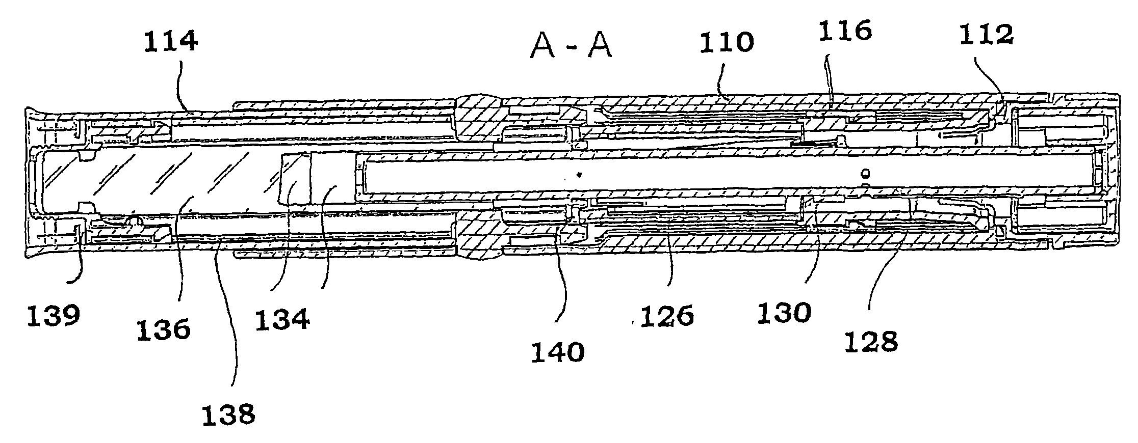
利用这一原理的示例性实施例显示在图7-15中。一种注射设备包括大致管状主体110,致动旋钮(activation knob)112和针头罩114,如图7所示。Exemplary embodiments utilizing this principle are shown in Figures 7-15. An injection device includes a generally
针头罩114可滑动地设置在主壳体内并与针头罩连杆116连接,如图8和9所示。为了清楚起见,在图9中主体被移走。针头罩连杆设置具有上(图9中右侧)管状部分118和两个纵向延伸臂120。臂的端部设置具有向外延伸的凸台122,该凸台配合进入针头罩上部中的凹部或通道124内,由此获得针头罩和针头罩连杆之间的连接。A
针头罩连杆内部,大致管状的构件126(后文中称为旋转器)可旋转且可滑动地设置。在它的外表面上设置具有多个脊和突出部,这些脊和突出部与设置在针头罩连杆内表面上的引导构件协同工作,其功能将在下文中介绍。旋转器的上端面与致动旋钮112的下端面连接,防止纵向运动但允许它们之间的旋转运动。在旋转器内,柱塞128被设置为可滑动并借助注射弹簧而可移动。柱塞的上部设置有多个向外延伸的止动构件130,设置为与致动旋钮内表面上的向内延伸的止动构件132协同工作,将在下文中介绍。柱塞的前端与止动部134接触,该止动部134设置在装有将输送给患者的药剂的药筒136内。药筒容装在保持器138中。药筒通过与保持器搭扣配合的端部件139被保持在保持器中。旋转器的下端面与保持器的端壁140接触。保持器通过针头罩经由沟槽141而引导,如图13所示。Inside the needle shield linkage, a generally tubular member 126 (hereinafter referred to as a rotator) is rotatably and slidably disposed. On its outer surface is provided a plurality of ridges and protrusions which cooperate with guide members provided on the inner surface of the needle shield linkage, the function of which will be described below. The upper end face of the rotator is connected to the lower end face of the
针头罩弹簧(未示出)设置为压在针头罩连杆上,壳体上的凸台和针头罩连杆上部凸台之间。The needle cover spring (not shown) is arranged to press on the needle cover connecting rod, between the boss on the housing and the upper boss of the needle cover connecting rod.
设备运行如下。当设备被组装且输送给使用者时,针头罩处于主壳体内的退回位置,如图8所示,通过致动旋钮112上的向外延伸的旋钮(extendingknob)140保持在该位置处并抵抗针头罩弹簧的力,该旋钮140邻接针头罩116内表面上的向内延伸旋钮142,如图11所示。The device operates as follows. When the device is assembled and delivered to the user, the needle shield is in the retracted position within the main housing, as shown in FIG. Due to the force of the needle shield spring, the
柱塞128位于最后面位置且注射弹簧张紧。柱塞通过一套反向设置的向外延伸的旋钮144而被保持在该位置上,如图10所示,该旋钮144在柱塞128上,与设置在致动旋钮112的内表面上的第一套凸台146邻接。凸台146设置有纵向延伸的突出部148,用于允许在旋钮144和凸台146之间仅在一个方向上的运动。The
当患者要使用设备时,通过常规装置新的针头安装在药筒的下前部,该常规装置如螺丝等。因为,针头罩处在退回位置,在安装针头期间药筒末端能容易地接近。When the device is to be used by the patient, a new needle is mounted on the lower front of the cartridge by conventional means, such as a screw or the like. Since, the needle shield is in the retracted position, the cartridge end is easily accessible during installation of the needle.
此后,设备被灌注。致动旋钮随后从锁定位置被旋转至开始位置,如图13所示,该开始位置能被显示在临近致动旋钮的主壳体上。旋钮的转动使柱塞128的向外延伸旋钮144从致动旋钮的凸台146上滑落,由此注射弹簧的力将柱塞推向药筒并由此移动在药筒内部的止动部,由此通过针头将任何空气和一些液体压出药筒。当柱塞的向外延伸旋钮144邻靠在第二套凸台149上时,运动停止,如图14所示,该第二套凸台149设置在旋转器的上部的内表面上。Thereafter, the device is primed. The actuation knob is then rotated from the locked position to the start position, which can be displayed on the main housing adjacent the actuation knob, as shown in FIG. 13 . Rotation of the knob causes the outwardly extending
致动旋钮的转动还使旋转器的向外延伸的旋钮140移动而不与针头罩连杆116的向内延伸的旋钮142接触。针头罩弹簧的力随后使针头罩和针头罩连杆移动至伸出位置(extended position),由此从视野范围内遮盖针头,如图13所示。针头罩连杆的内表面设置有引导旋钮,该引导旋钮在向伸出位置运动期间沿引导表面150行进,如图11所示,该引导表面150具有关于设备纵向方向的倾斜度。这导致旋转器关于针头罩连杆能作某种程度的转动。Rotation of the actuation knob also moves the outwardly extending
设备已经准备好用于注射了。针头罩被压靠在注射点且针头刺入皮肤。在针头罩向内运动期间,针头罩连杆的引导旋钮沿纵向延伸的脊152行进,如图12所示,直到它们与倾斜的凸台154接触。这些部件之间的接触使旋转器在针头罩和针头罩连杆的进一步运动期间能够转动。旋转器由此转动,直到柱塞的向外延伸的旋钮134从第二套凸台上滑落,该第二套凸台设置在旋转器的上部,由此开始注射。由于注射弹簧的力柱塞向下移动,且旋钮134在旋转器内表面上的纵向沟槽中行进。柱塞的运动使止动部移动,由此药剂通过针头排出,直到柱塞的向外延伸的旋钮134邻靠在壁140上,如图14所示。The device is ready for injection. The needle shield is pressed against the injection site and the needle penetrates the skin. During inward movement of the needle shield, the guide knobs of the needle shield linkage travel along the
当注射完成时,使用者从注射点移走设备,由此针头罩和针头罩连杆移动进入伸出位置。针头罩连杆的引导旋钮沿脊152的另一侧移动,且当针头罩处于遮盖针头的最大伸出的位置时,在沿这一路径的某一位置处,引导旋钮装入旋转器的凹部中,由此将针头罩锁定在伸出位置,防止针头罩被再次推入,如图15所示。由此消除了不经意间被针头刺到的危险。When the injection is complete, the user removes the device from the injection site whereby the needle shield and needle shield linkage move into the extended position. The guide knob of the needle shield linkage moves along the other side of the
图16-26显示了本发明的第二实施例。该第二实施例包括进一步的特征,即剂量设定装置。该特征能使注射器可用于取决于疾病类型和/或患者类型的不同药剂和/或不同剂量。以该特征,相同的注射器可用于输送不同的剂量,而不取决于注射器的设计。第一实施例具有能使用某一剂量的设计,该剂量取决于实际的设计情况或注射器的行程,这反过来意味着如果想要注射器用于不同剂量,则必须改变设计以及塑性模制形式。当药剂总是以一定的量输送时,之前的设计是完全可以使用的。16-26 show a second embodiment of the invention. This second embodiment includes a further feature, namely dose setting means. This feature enables the syringe to be used for different medicaments and/or different dosages depending on the type of disease and/or the type of patient. With this feature, the same syringe can be used to deliver different doses, independent of the design of the syringe. The first embodiment has a design that can use a dose that depends on the actual design situation or the travel of the syringe, which in turn means that if the syringe is intended for a different dose, the design and plastic molded form must be changed. The previous design is perfectly fine when the medicament is always delivered in a certain amount.
如所述的,第二实施例的主要不同之处在于剂量设定功能。其包括第二普通管状构件202,设置在剂量设定旋钮112和旋转器126之间,如图16所示。通过向外伸出的、反向地设置的爪203,管状构件202可旋转地锁定到剂量设定旋钮上,如图18所示,剂量设定旋钮上的相应的向内延伸爪装配到在该爪203之间。对于第一实施例,柱塞通过在柱塞128上的一套相反设置、向外延伸的旋钮206而被保持在初始位置,如图21所示,旋钮206邻接于设置在剂量设置旋钮112的内表面的第一系列凸台204上。凸台以与第一实施例相同的方式设置。如图23所示,在将针头安装在注射器前端之后,为了灌注旋钮向开始位置的旋转使旋钮从凸台上滑落。柱塞弹簧的力将柱塞向前推动,排出药筒中的任何空气。当柱塞的向外延伸的旋钮144邻接第二套凸台149时运动停止,如第一实施例那样,该第二套凸台149设置在旋转器126的内表面。As stated, the main difference of the second embodiment is the dose setting function. It comprises a second generally tubular
剂量设定旋钮可自由转动,以设置某一剂量,如图20所示。如图17所示,为了这一目的,管状构件202的内表面设置具有一系列凸台208,距离注射器的上端有一定距离处,形成一套渐低的凸台。每个凸台对应要被输送的某一剂量。旋钮的转动通过合适的符号或标记来指示,以告知使用者设定了什么剂量。如图20所示,距离x对应于在注射期间柱塞要行进的长度,且由此对应于输送剂量。The dose setting knob can be rotated freely to set a certain dose, as shown in Figure 20. As shown in Figure 17, for this purpose the inner surface of the
设备已经准备好用于注射。如图21和22所示,当将设备压靠在注射点并刺入皮肤时,针头罩连杆的引导旋钮使旋转器旋转,如第一实施例那样,由此,柱塞的向外延伸的旋钮从第二套凸台149上滑落。这导致柱塞向前移动从而引起注射,直到向外延伸的旋钮206邻接其中一个渐低的凸台208,该凸台208是针对某一剂量设定的,如图22所示。The device is ready for injection. As shown in Figures 21 and 22, when the device is pressed against the injection site and penetrates the skin, the guide knob of the needle shield linkage rotates the rotator, as in the first embodiment, whereby the outward extension of the plunger The knob slides off from the second set of
当注射完成时,使用者移走设备,且通过设备执行如第一实施例那样的相同的操作,如图23所示。When the injection is complete, the user removes the device, and performs the same operations through the device as in the first embodiment, as shown in FIG. 23 .
图25和26显示了与旋转器126连接的管状构件202的变化例202’。该变化例将被放置在旋转器126和保持器的端壁140之间,而不是放置在剂量设定旋钮和旋转器之间。旋转器设置有第二止动凸台149,在灌注之后柱塞的旋钮144位于该凸台149上。当由于针头罩在刺入期间被推动而使旋转器转动时,如上所述的,旋钮从凸台149上被推落,并由于注射弹簧的力以及由此柱塞的向前运动而沿沟槽210向下行进,导致注射。当旋钮碰到管状构件202’的其中一个剂量凸台208时,注射停止。图26显示了如何以旋转器位于管状构件202’和旋钮之间的结构形式,将管状构件202’安装到剂量设定旋钮上的。25 and 26 show a variation 202' This variation would be placed between the
上面描述的是,柱塞从锁定输送位置到由第一止动凸台限定的位置的运动,该运动是灌注的结束,即使药筒136脱气。其还描述了,对于双腔室药筒,该运动包括混合步骤,即柱塞将药筒内部的止动部移动到一位置,在该位置处,包含在药筒中且最初通过止动部而彼此保持分离的两种物质被混合。由于从柱塞向混合溶液施加的压力,随后的针头的安装导致对被混合的药筒的灌注,由此,柱塞能向前移动到止动凸台,且准备好用于注射。在这种情况下,柱塞的用于混合的行进通常须比仅用于灌注的行进更长,但这种设计差异很容易在注射器设计概念内实现。Described above is the movement of the plunger from the locked delivery position to the position defined by the first stop boss, which is the end of priming, ie degassing of the
在所示的实施例中,针头罩被保持在位于壳体内的回退位置,直到其活动。当然能想到的是,针头罩一开始处于延伸位置且仅在刺入和注射期间处于回退位置。进而,尽管在实施例的描述中描述了药筒,但其他类型的药剂容纳壳罩也可使用,如安瓿,容器等。In the illustrated embodiment, the needle shield is held in a retracted position within the housing until activated. It is of course conceivable that the needle shield is initially in the extended position and only in the retracted position during penetration and injection. Furthermore, although cartridges have been described in the description of the embodiments, other types of medicament containment enclosures may be used, such as ampoules, containers, and the like.
应理解,应将以上描述并显示的本发明的实施例认为是非限制性的实施例且在专利权利要求的范围内可做修改。It will be understood that the embodiments of the invention described and shown above are to be considered as non-limiting embodiments and that modifications may be made within the scope of the patent claims.
Claims (13)
Applications Claiming Priority (6)
| Application Number | Priority Date | Filing Date | Title |
|---|---|---|---|
| US63019704P | 2004-11-24 | 2004-11-24 | |
| US60/630,197 | 2004-11-24 | ||
| SE0502370 | 2005-10-25 | ||
| SE0502370-0 | 2005-10-25 | ||
| SE05023700 | 2005-10-25 | ||
| PCT/SE2005/001764 WO2006057604A1 (en) | 2004-11-24 | 2005-11-24 | Injection device |
Publications (2)
| Publication Number | Publication Date |
|---|---|
| CN101119761A true CN101119761A (en) | 2008-02-06 |
| CN101119761B CN101119761B (en) | 2010-08-18 |
Family
ID=36498273
Family Applications (1)
| Application Number | Title | Priority Date | Filing Date |
|---|---|---|---|
| CN2005800471032A Expired - Lifetime CN101119761B (en) | 2004-11-24 | 2005-11-24 | Injection device |
Country Status (8)
| Country | Link |
|---|---|
| US (5) | US7597685B2 (en) |
| EP (4) | EP2438948B1 (en) |
| CN (1) | CN101119761B (en) |
| AU (1) | AU2005310060B2 (en) |
| CA (1) | CA2587408C (en) |
| DK (1) | DK1814615T3 (en) |
| ES (1) | ES2557778T3 (en) |
| WO (1) | WO2006057604A1 (en) |
Cited By (13)
| Publication number | Priority date | Publication date | Assignee | Title |
|---|---|---|---|---|
| CN103037921A (en) * | 2010-04-30 | 2013-04-10 | 拜耳药业股份公司 | Displacement Syringe |
| CN103347557A (en) * | 2010-11-18 | 2013-10-09 | Shl集团有限责任公司 | Medicament delivery device |
| CN103442756A (en) * | 2011-01-11 | 2013-12-11 | Shl集团有限责任公司 | Medicament delivery device |
| CN103945881A (en) * | 2011-09-27 | 2014-07-23 | Shl集团有限责任公司 | Medical delivery device with an initial locked state, intermediate priming state and a medicament delivery state |
| CN104379196A (en) * | 2012-06-29 | 2015-02-25 | 诺和诺德A/S(股份有限公司) | Shield lock for spring driven injection device |
| CN105517599A (en) * | 2013-07-09 | 2016-04-20 | 赛诺菲-安万特德国有限公司 | auto injector |
| CN106068135A (en) * | 2014-03-06 | 2016-11-02 | 卡贝欧洲有限公司 | The apparatus and method of conveying medicine |
| CN106102801A (en) * | 2014-03-28 | 2016-11-09 | 赛诺菲-安万特德国有限公司 | The automatic injector being triggered by skin contact |
| CN106255522A (en) * | 2014-05-06 | 2016-12-21 | 卡贝欧洲有限公司 | There is the delivery device of the rotator keeping plunger rod |
| CN106456877A (en) * | 2014-02-12 | 2017-02-22 | 新注射系统有限公司 | Injector assembly |
| CN108066851A (en) * | 2017-12-28 | 2018-05-25 | 江苏万海医疗器械有限公司 | Injection device |
| CN111526904A (en) * | 2017-11-03 | 2020-08-11 | 赛诺菲 | Drug delivery device |
| CN112188906A (en) * | 2018-05-24 | 2021-01-05 | 诺华股份有限公司 | Automatic drug delivery device |
Families Citing this family (178)
| Publication number | Priority date | Publication date | Assignee | Title |
|---|---|---|---|---|
| WO2003068290A2 (en) | 2002-02-11 | 2003-08-21 | Antares Pharma, Inc. | Intradermal injector |
| US9486581B2 (en) | 2002-09-11 | 2016-11-08 | Becton, Dickinson And Company | Injector device with force lock-out and injection rate limiting mechanisms |
| CH696421A5 (en) | 2003-12-18 | 2007-06-15 | Tecpharma Licensing Ag | Autoinjector with arresting the drug container. |
| EP2438948B1 (en) * | 2004-11-24 | 2016-03-30 | SHL Group AB | Tubular rotator for a medicament injection device, and medicament injection device |
| EP3495009B2 (en) | 2005-01-24 | 2025-01-15 | Antares Pharma, Inc. | An injector with prefilled syringe |
| US9144648B2 (en) | 2006-05-03 | 2015-09-29 | Antares Pharma, Inc. | Injector with adjustable dosing |
| WO2007131013A1 (en) | 2006-05-03 | 2007-11-15 | Antares Pharma, Inc. | Two-stage reconstituting injector |
| US7993264B2 (en) | 2006-11-09 | 2011-08-09 | Ams Research Corporation | Orientation adapter for injection tube in flexible endoscope |
| DE102007016811A1 (en) | 2007-04-05 | 2008-10-09 | Tecpharma Licensing Ag | Device for administering a fluid substance from a multi-chamber ampoule |
| DE102007030327A1 (en) | 2007-06-29 | 2009-01-02 | Tecpharma Licensing Ag | Injection device with a spring for a needle protection sleeve |
| DK2170435T3 (en) | 2007-07-19 | 2018-02-12 | Shl Group Ab | AUTOMATIC DEVICE FOR THE DELIVERY OF A MEDICINE |
| DE102007034871A1 (en) * | 2007-07-24 | 2009-01-29 | Lts Lohmann Therapie-Systeme Ag | Disposable injector with manually operated piston |
| WO2009040602A1 (en) * | 2007-09-25 | 2009-04-02 | Becton Dickinson France | Autoinject0r with deactivating means moveable by a safety shield |
| CN101868273B (en) | 2007-10-02 | 2014-10-15 | 莱蒙德尔有限公司 | External drug pump |
| US10420880B2 (en) | 2007-10-02 | 2019-09-24 | West Pharma. Services IL, Ltd. | Key for securing components of a drug delivery system during assembly and/or transport and methods of using same |
| US9656019B2 (en) | 2007-10-02 | 2017-05-23 | Medimop Medical Projects Ltd. | Apparatuses for securing components of a drug delivery system during transport and methods of using same |
| US9345836B2 (en) | 2007-10-02 | 2016-05-24 | Medimop Medical Projects Ltd. | Disengagement resistant telescoping assembly and unidirectional method of assembly for such |
| US7967795B1 (en) | 2010-01-19 | 2011-06-28 | Lamodel Ltd. | Cartridge interface assembly with driving plunger |
| EP2990067B1 (en) | 2008-03-10 | 2019-09-04 | Antares Pharma, Inc. | Injector safety device |
| WO2009114777A1 (en) | 2008-03-13 | 2009-09-17 | Becton, Dickinson And Company | Safety needle assembly |
| EP3527246B1 (en) | 2008-03-13 | 2022-02-16 | Becton, Dickinson and Company | Safety pen needle assembly having shield for non-patient end |
| ES2615954T3 (en) | 2008-03-13 | 2017-06-08 | Becton, Dickinson And Company | Pen needle safety set with end protection for the patient and not for the patient |
| US8414554B2 (en) | 2008-05-14 | 2013-04-09 | J & J Solutions, Inc. | Systems and methods for safe medicament transport |
| US8177749B2 (en) | 2008-05-20 | 2012-05-15 | Avant Medical Corp. | Cassette for a hidden injection needle |
| CA3070618C (en) | 2008-05-20 | 2021-07-20 | Avant Medical Corp. | Autoinjector system |
| US8052645B2 (en) | 2008-07-23 | 2011-11-08 | Avant Medical Corp. | System and method for an injection using a syringe needle |
| JP5611208B2 (en) | 2008-08-05 | 2014-10-22 | アンタレス・ファーマ・インコーポレーテッド | Multiple dose injection device |
| GB2463071A (en) * | 2008-09-02 | 2010-03-03 | Owen Mumford Ltd | Auto-injector syringe with safety shield |
| US9393369B2 (en) | 2008-09-15 | 2016-07-19 | Medimop Medical Projects Ltd. | Stabilized pen injector |
| US12097357B2 (en) | 2008-09-15 | 2024-09-24 | West Pharma. Services IL, Ltd. | Stabilized pen injector |
| US8323238B2 (en) * | 2008-09-18 | 2012-12-04 | Becton, Dickinson And Company | Medical injector with rotatable body portions |
| US20100145305A1 (en) * | 2008-11-10 | 2010-06-10 | Ruth Alon | Low volume accurate injector |
| JP5701219B2 (en) | 2008-12-05 | 2015-04-15 | エーエムエス リサーチ コーポレイション | Devices, systems, and related methods for delivery of fluids to tissue |
| US8366657B2 (en) | 2008-12-05 | 2013-02-05 | Ams Research Corporation | Needleless injection device components, systems, and methods |
| CA2744411C (en) * | 2008-12-05 | 2018-03-27 | Ams Research Corporation | Devices, systems and methods for delivering fluid to tissue |
| US8876759B2 (en) | 2008-12-05 | 2014-11-04 | Ams Research Corporation | Devices, systems and methods for delivering fluid to tissue |
| CA2744414A1 (en) | 2008-12-16 | 2010-07-01 | Ams Research Corporation | Needleless injection device components, systems, and methods |
| WO2010077271A2 (en) | 2008-12-29 | 2010-07-08 | Ams Research Corporation | Method and apparatus for compensating for injection media viscosity in a pressurized drug injection system |
| GB0900930D0 (en) * | 2009-01-20 | 2009-03-04 | Future Injection Technologies Ltd | Injection device |
| WO2010108116A1 (en) | 2009-03-20 | 2010-09-23 | Antares Pharma, Inc. | Hazardous agent injection system |
| TWI519330B (en) | 2009-06-02 | 2016-02-01 | 賽諾菲阿凡提斯德意志有限公司 | Medicated module with user selection |
| WO2011011392A2 (en) | 2009-07-20 | 2011-01-27 | Ams Research Corporation | Needleless injection device components, systems, and methods |
| WO2011011406A1 (en) | 2009-07-20 | 2011-01-27 | Ams Research Corporation | Devices, systems, and methods for delivering fluid to tissue |
| WO2011011396A1 (en) | 2009-07-20 | 2011-01-27 | Ams Research Corporation | High pressure injection catheter systems |
| WO2011011372A2 (en) | 2009-07-20 | 2011-01-27 | Ams Research Corporation | Needleless injection device components, systems, and methods |
| JP5703299B2 (en) * | 2009-09-07 | 2015-04-15 | サノフィ−アベンティス・ドイチュラント・ゲゼルシャフト・ミット・ベシュレンクテル・ハフツング | Drive mechanism for drug delivery device |
| US8157769B2 (en) | 2009-09-15 | 2012-04-17 | Medimop Medical Projects Ltd. | Cartridge insertion assembly for drug delivery system |
| US10071196B2 (en) | 2012-05-15 | 2018-09-11 | West Pharma. Services IL, Ltd. | Method for selectively powering a battery-operated drug-delivery device and device therefor |
| US10071198B2 (en) | 2012-11-02 | 2018-09-11 | West Pharma. Servicees IL, Ltd. | Adhesive structure for medical device |
| DK2482889T3 (en) * | 2009-09-30 | 2016-05-17 | Sanofi Aventis Deutschland | ACCOMMODATION drug delivery device |
| US20120283652A1 (en) * | 2009-09-30 | 2012-11-08 | Sanofi-Aventis Deutschland Gmbh | Assembly and Piston Rod for a Drug Delivery Device |
| US8348898B2 (en) | 2010-01-19 | 2013-01-08 | Medimop Medical Projects Ltd. | Automatic needle for drug pump |
| DK2536452T3 (en) | 2010-02-18 | 2019-01-02 | Sanofi Aventis Deutschland | autoinjector |
| IT1398501B1 (en) * | 2010-03-10 | 2013-03-01 | Menarini Int Operations Lu Sa | AUTOINECTOR DEVICE FOR TWO DRUG DOSES |
| WO2011141907A1 (en) | 2010-05-10 | 2011-11-17 | Medimop Medical Projects Ltd. | Low volume accurate injector |
| EP2399635A1 (en) | 2010-06-28 | 2011-12-28 | Sanofi-Aventis Deutschland GmbH | Auto-injector |
| ES2538371T3 (en) * | 2010-07-02 | 2015-06-19 | Sanofi-Aventis Deutschland Gmbh | Safety device for a prefilled syringe and injection device |
| PL2555820T3 (en) | 2010-07-02 | 2015-08-31 | Carebay Holding Ltd Company No 681498 | Preservative-free follicle stimulating hormone solution delivery device |
| TWI459984B (en) * | 2010-11-18 | 2014-11-11 | Shl Group Ab | Medicament delivery device |
| JP5963764B2 (en) * | 2010-11-29 | 2016-08-03 | サノフィ−アベンティス・ドイチュラント・ゲゼルシャフト・ミット・ベシュレンクテル・ハフツング | Medicinal module with automatic reservoir engagement |
| AU2011335079B2 (en) | 2010-11-29 | 2014-06-12 | Sanofi-Aventis Deutschland Gmbh | Medicated module with automatic reservoir engagement |
| US8979797B2 (en) | 2010-12-16 | 2015-03-17 | Ams Research Corporation | High pressure delivery system and method for treating pelvic disorder using large molecule therapeutics |
| EP2468333A1 (en) | 2010-12-21 | 2012-06-27 | Sanofi-Aventis Deutschland GmbH | Auto-injector |
| EP2468336A1 (en) | 2010-12-21 | 2012-06-27 | Sanofi-Aventis Deutschland GmbH | Auto-injector |
| EP2468332A1 (en) * | 2010-12-21 | 2012-06-27 | Sanofi-Aventis Deutschland GmbH | Auto-injector |
| EP2468330A1 (en) | 2010-12-21 | 2012-06-27 | Sanofi-Aventis Deutschland GmbH | Auto-injector |
| USRE48593E1 (en) | 2010-12-21 | 2021-06-15 | Sanofi-Aventis Deutschland Gmbh | Auto-injector |
| CA2825445C (en) | 2011-01-24 | 2017-11-07 | Elcam Medical Agricultural Cooperative Association Ltd. | Cover removal assembly for an injector |
| EP2489385A1 (en) | 2011-02-18 | 2012-08-22 | Sanofi-Aventis Deutschland GmbH | Auto-injector |
| EP2489389A1 (en) | 2011-02-18 | 2012-08-22 | Sanofi-Aventis Deutschland GmbH | Detent mechanism |
| WO2012122643A1 (en) * | 2011-03-11 | 2012-09-20 | University Of Saskatchewan | Injection assist device and method |
| USD702834S1 (en) | 2011-03-22 | 2014-04-15 | Medimop Medical Projects Ltd. | Cartridge for use in injection device |
| CA3021845C (en) | 2011-04-20 | 2022-03-29 | Amgen Inc. | Autoinjector apparatus |
| WO2012166527A2 (en) * | 2011-06-02 | 2012-12-06 | West Pharmaceutical Services Inc. | Needle-protection device for a syringe |
| MX357609B (en) * | 2011-06-17 | 2018-07-17 | Sanofi Aventis Deutschland | Cartridge holder assembly for drug delivery devices. |
| US9220660B2 (en) | 2011-07-15 | 2015-12-29 | Antares Pharma, Inc. | Liquid-transfer adapter beveled spike |
| US8496619B2 (en) | 2011-07-15 | 2013-07-30 | Antares Pharma, Inc. | Injection device with cammed ram assembly |
| CH705345A2 (en) * | 2011-08-04 | 2013-02-15 | Tecpharma Licensing Ag | Injector with needle protection device. |
| ITFI20110194A1 (en) | 2011-09-08 | 2013-03-09 | Menarini Int Operations Lu Sa | MEDICINE DOSES SELF-INJECTION DEVICE |
| EP2572741A1 (en) | 2011-09-23 | 2013-03-27 | Sanofi-Aventis Deutschland GmbH | Medicament delivery device and actuation mechanism for a drug delivery device |
| EP2601992A1 (en) | 2011-12-08 | 2013-06-12 | Sanofi-Aventis Deutschland GmbH | Syringe carrier |
| KR101621183B1 (en) * | 2011-12-15 | 2016-05-23 | 에스에이치엘 그룹 에이비 | Cap assembly |
| EP2606924A1 (en) | 2011-12-21 | 2013-06-26 | Sanofi-Aventis Deutschland GmbH | Autoinjector having a retracting syringe carrier |
| EP2822618B1 (en) | 2012-03-06 | 2024-01-10 | Antares Pharma, Inc. | Prefilled syringe with breakaway force feature |
| US10004854B2 (en) | 2012-03-07 | 2018-06-26 | West Pharmaceutical Services, Inc. | Low radial profile needle safety device |
| EP2822621B1 (en) * | 2012-03-07 | 2016-09-21 | West Pharmaceutical Services, Inc. | Low radial profile needle safety device |
| US9072827B2 (en) | 2012-03-26 | 2015-07-07 | Medimop Medical Projects Ltd. | Fail safe point protector for needle safety flap |
| CN104487114A (en) | 2012-04-06 | 2015-04-01 | 安塔雷斯药品公司 | Needle assisted jet injection administration of testosterone compositions |
| USD808010S1 (en) | 2012-04-20 | 2018-01-16 | Amgen Inc. | Injection device |
| USD898908S1 (en) | 2012-04-20 | 2020-10-13 | Amgen Inc. | Pharmaceutical product cassette for an injection device |
| WO2013169804A1 (en) | 2012-05-07 | 2013-11-14 | Antares Pharma, Inc. | Needle assisted jet injection device having reduced trigger force |
| EP2719414A1 (en) | 2012-10-15 | 2014-04-16 | Sanofi-Aventis Deutschland GmbH | Medicament delivery device with use indicator |
| CN104968381B (en) * | 2012-12-21 | 2017-07-04 | 卡贝欧洲有限公司 | drug delivery device |
| US9421323B2 (en) | 2013-01-03 | 2016-08-23 | Medimop Medical Projects Ltd. | Door and doorstop for portable one use drug delivery apparatus |
| DK3659647T3 (en) * | 2013-02-11 | 2024-04-22 | Antares Pharma Inc | Needle-assisted jet injection device with reduced trigger force |
| WO2014164786A1 (en) | 2013-03-11 | 2014-10-09 | Madsen Patrick | Dosage injector with pinion system |
| WO2014165136A1 (en) | 2013-03-12 | 2014-10-09 | Antares Pharma, Inc. | Constant volume prefilled syringes and kits thereof |
| EP2777684A1 (en) | 2013-03-14 | 2014-09-17 | Sanofi-Aventis Deutschland GmbH | Medicament container carrier and adapter |
| TWI639453B (en) | 2013-03-15 | 2018-11-01 | 美商安美基公司 | Cassette for an injector |
| JP6336564B2 (en) | 2013-03-15 | 2018-06-06 | アムゲン・インコーポレーテッド | Drug cassette, auto-injector, and auto-injector system |
| EP2781230B2 (en) | 2013-03-22 | 2025-05-14 | Ypsomed AG | Substance dispensing device with a signaling device |
| DE102013007389A1 (en) * | 2013-04-30 | 2014-10-30 | Britannia Pharmaceuticals Ltd. | Drug delivery device |
| US9011164B2 (en) | 2013-04-30 | 2015-04-21 | Medimop Medical Projects Ltd. | Clip contact for easy installation of printed circuit board PCB |
| EP2823836A1 (en) | 2013-07-09 | 2015-01-14 | Sanofi-Aventis Deutschland GmbH | Autoinjector |
| EP2823838A1 (en) | 2013-07-09 | 2015-01-14 | Sanofi-Aventis Deutschland GmbH | Autoinjector |
| WO2015026737A1 (en) * | 2013-08-19 | 2015-02-26 | Dr. Reddy's Laboratories, Ltd. | Selectable single dose auto-injector and methods of making and using same |
| US9623194B2 (en) | 2013-12-10 | 2017-04-18 | Becton, Dickinson And Company | Passive safety pen needle assembly |
| CA2873770A1 (en) | 2013-12-10 | 2015-06-10 | Becton, Dickinson And Company | Active safety pen needle assembly |
| WO2015188997A1 (en) * | 2014-06-10 | 2015-12-17 | Carebay Europe Ltd | Plunger segments drive mechanism for a medicament delivery device |
| CH707898A2 (en) | 2014-07-29 | 2014-10-15 | Tecpharma Licensing Ag | Autoinjector with adjustable dose. |
| KR20170097020A (en) | 2014-12-23 | 2017-08-25 | 오토메드 피티와이 리미티드 | Delivery apparatus, system and associated methods |
| US10293120B2 (en) | 2015-04-10 | 2019-05-21 | West Pharma. Services IL, Ltd. | Redundant injection device status indication |
| US10149943B2 (en) | 2015-05-29 | 2018-12-11 | West Pharma. Services IL, Ltd. | Linear rotation stabilizer for a telescoping syringe stopper driverdriving assembly |
| TW201700117A (en) | 2015-06-03 | 2017-01-01 | 賽諾菲阿凡提斯德意志有限公司 | Syringe bracket and assembly method for autoinjector |
| TW201707737A (en) | 2015-06-03 | 2017-03-01 | 賽諾菲阿凡提斯德意志有限公司 | Drug delivery device (1) |
| TW201707738A (en) | 2015-06-03 | 2017-03-01 | 賽諾菲阿凡提斯德意志有限公司 | Syringe holder and autoinjector (2) |
| TW201700118A (en) | 2015-06-03 | 2017-01-01 | 賽諾菲阿凡提斯德意志有限公司 | Drug delivery device (3) |
| EP4252798A3 (en) | 2015-06-04 | 2023-10-25 | Medimop Medical Projects Ltd. | Cartridge insertion for drug delivery device |
| EP3341044B1 (en) * | 2015-08-25 | 2020-01-29 | Novo Nordisk A/S | A medical injection device with a cleaning chamber |
| JP6895142B2 (en) | 2015-09-17 | 2021-06-30 | ジェイ アンド ジェイ ソリューションズ,インコーポレイテッド | Drug vial assembly |
| US9987432B2 (en) | 2015-09-22 | 2018-06-05 | West Pharma. Services IL, Ltd. | Rotation resistant friction adapter for plunger driver of drug delivery device |
| US10576207B2 (en) | 2015-10-09 | 2020-03-03 | West Pharma. Services IL, Ltd. | Angled syringe patch injector |
| CN108430536B (en) | 2015-10-09 | 2022-04-08 | 西医药服务以色列分公司 | Method of filling a custom syringe |
| JP2018530396A (en) | 2015-10-13 | 2018-10-18 | ジェイ アンド ジェイ ソリューションズ,インコーポレイテッド | Automatic compounding equipment for closed fluid transfer systems. |
| US11311674B2 (en) | 2016-01-21 | 2022-04-26 | West Pharma. Services IL, Ltd. | Medicament delivery device comprising a visual indicator |
| WO2017127215A1 (en) | 2016-01-21 | 2017-07-27 | Medimop Medical Projects Ltd. | Needle insertion and retraction mechanism |
| JP6513297B2 (en) | 2016-01-21 | 2019-05-22 | ウェスト ファーマ サービシーズ イスラエル リミテッド | Automatic injector, receiving frame and method of connecting cartridge in automatic injector |
| CH710381A2 (en) * | 2016-02-25 | 2016-05-13 | Tecpharma Licensing Ag | Injection device for up-dosing and the distribution of a dose of a fluid product. |
| WO2017161076A1 (en) | 2016-03-16 | 2017-09-21 | Medimop Medical Projects Ltd. | Staged telescopic screw assembly having different visual indicators |
| USD819198S1 (en) | 2016-04-28 | 2018-05-29 | Amgen Inc. | Autoinjector with removable cap |
| JP6957525B2 (en) | 2016-06-02 | 2021-11-02 | ウェスト ファーマ サービシーズ イスラエル リミテッド | Needle evacuation by 3 positions |
| EP3469573B1 (en) * | 2016-06-08 | 2024-02-07 | SHL Medical AG | Administration mechanism for a medicament delivery training device |
| WO2018026387A1 (en) | 2016-08-01 | 2018-02-08 | Medimop Medical Projects Ltd. | Anti-rotation cartridge pin |
| CN109562220B (en) | 2016-08-01 | 2021-06-29 | 西医药服务以色列有限公司 | Partial door closing prevents spring |
| ES2958593T3 (en) | 2016-09-23 | 2024-02-12 | Hoffmann La Roche | Uses of IL-13 antagonists for the treatment of atopic dermatitis |
| US11376364B2 (en) | 2017-03-15 | 2022-07-05 | Owen Mumford Limited | Injection apparatus |
| GB2560557A (en) * | 2017-03-15 | 2018-09-19 | Owen Mumford Ltd | Injection Device |
| JP6921997B2 (en) | 2017-05-30 | 2021-08-18 | ウェスト ファーマ サービシーズ イスラエル リミテッド | Modular drive train for wearable syringes |
| JP7402799B2 (en) | 2017-12-22 | 2023-12-21 | ウェスト ファーマ サービシーズ イスラエル リミテッド | Syringes available with different cartridge sizes |
| JOP20200220A1 (en) | 2018-03-13 | 2020-09-07 | Coalesce Product Development Ltd | Devices for injecting drugs and methods of use |
| US10532049B1 (en) | 2018-08-27 | 2020-01-14 | Pharmaceutical Industries Limited | Parenteral unit dosage form of dihydroergotamine |
| GB2577538B (en) | 2018-09-28 | 2021-10-13 | Owen Mumford Ltd | Injection device fill volume management |
| GB2577537A (en) * | 2018-09-28 | 2020-04-01 | Owen Mumford Ltd | Injection device fill volume management |
| KR20210117266A (en) * | 2019-01-14 | 2021-09-28 | 필립모리스 프로덕츠 에스.에이. | dry powder inhaler |
| JP2022549349A (en) | 2019-09-30 | 2022-11-24 | アムジエン・インコーポレーテツド | drug delivery device |
| USD1010811S1 (en) | 2019-09-30 | 2024-01-09 | Amgen Inc. | Handheld drug delivery device |
| US12102808B2 (en) | 2019-09-30 | 2024-10-01 | Amgen Inc. | Drug delivery device |
| BR112022005814A2 (en) | 2019-09-30 | 2022-06-21 | Amgen Inc | drug delivery device |
| FI4037735T3 (en) | 2019-09-30 | 2025-11-25 | Amgen Inc | Drug delivery device |
| JP7439259B2 (en) | 2019-12-11 | 2024-02-27 | エスエイチエル・メディカル・アーゲー | drug delivery device |
| USD1030040S1 (en) | 2020-01-14 | 2024-06-04 | Amgen Inc. | Handheld drug delivery device |
| USD1030041S1 (en) | 2020-01-14 | 2024-06-04 | Amgen Inc. | Handheld drug delivery device |
| US11957542B2 (en) | 2020-04-30 | 2024-04-16 | Automed Patent Holdco, Llc | Sensing complete injection for animal injection device |
| USD962423S1 (en) | 2020-11-05 | 2022-08-30 | Amgen Inc. | Handheld drug delivery device |
| USD973866S1 (en) | 2020-11-05 | 2022-12-27 | Amgen Inc. | Handheld drug delivery device |
| USD974547S1 (en) | 2020-11-05 | 2023-01-03 | Amgen Inc. | Handheld drug delivery device |
| USD985117S1 (en) | 2021-03-10 | 2023-05-02 | Amgen Inc. | Handheld drug delivery device |
| USD985118S1 (en) | 2021-03-10 | 2023-05-02 | Amgen Inc. | Handheld drug delivery device |
| USD985116S1 (en) | 2021-03-10 | 2023-05-02 | Amgen Inc. | Handheld drug delivery device |
| USD985119S1 (en) | 2021-03-30 | 2023-05-02 | Amgen Inc. | Handheld drug delivery device |
| KR20240043760A (en) | 2021-09-01 | 2024-04-03 | 에스에이치엘 메디컬 아게 | Method of assembling a drug delivery device |
| US20250144319A1 (en) * | 2022-02-09 | 2025-05-08 | Shl Medical Ag | Rotator for a medicament delivery device |
| WO2024094635A1 (en) * | 2022-11-04 | 2024-05-10 | Shl Medical Ag | Medicament delivery device |
| EP4633703A1 (en) | 2022-12-15 | 2025-10-22 | SHL Medical AG | A sub-assembly of a medicament delivery device |
| EP4480517A1 (en) * | 2023-06-20 | 2024-12-25 | Ypsomed AG | Autoinjector for intravitreal injection |
| USD1108627S1 (en) | 2023-10-02 | 2026-01-06 | Regeneron Pharmaceuticals, Inc. | Drug-delivery device |
| USD1109322S1 (en) | 2023-10-02 | 2026-01-13 | Regeneron Pharmaceuticals, Inc. | Drug-delivery device |
| WO2025103769A1 (en) * | 2023-11-16 | 2025-05-22 | Shl Medical Ag | A subsassembly of a medicament delivery device for providing plunger motion |
| US12268858B1 (en) | 2024-03-04 | 2025-04-08 | Genzyme Corporation | Injector device |
| US12274873B1 (en) | 2024-03-04 | 2025-04-15 | Genzyme Corporation | Medicament delivery device |
| US20250276131A1 (en) | 2024-03-04 | 2025-09-04 | Genzyme Corporation | Medicament delivery device |
| US12274874B1 (en) | 2024-03-04 | 2025-04-15 | Genzyme Corporation | Injector device |
| US12274872B1 (en) | 2024-03-28 | 2025-04-15 | Genzyme Corporation | Collar hold detent mechanism and lock for injection devices |
| US12502482B2 (en) | 2024-03-28 | 2025-12-23 | Genzyme Corporation | Collar cam lock for injection devices |
| US12274875B1 (en) | 2024-03-28 | 2025-04-15 | Genzyme Corporation | Needle shroud latch for injection devices |
| US12427266B1 (en) | 2024-03-28 | 2025-09-30 | Genzyme Corporation | Needle shroud latch for injection devices |
| US12274871B1 (en) | 2024-03-28 | 2025-04-15 | Genzyme Corporation | Hold detent mechanism for injection devices |
| US12274866B1 (en) | 2024-03-28 | 2025-04-15 | Genzyme Corporation | Rotatable collar for injection devices |
Family Cites Families (31)
| Publication number | Priority date | Publication date | Assignee | Title |
|---|---|---|---|---|
| SE457417B (en) | 1987-04-14 | 1988-12-27 | Astra Meditec Ab | AUTOMATIC SQUARE SPRAY, PROCEDURE FOR MIXING AND INJECTION WITH THE SPRAYER AND AMPULA FOR PRIVATE CHAMBER SPRAY |
| IL86799A (en) | 1987-07-02 | 1993-03-15 | Kabi Pharmacia Ab | Method and device for injection |
| GB9007113D0 (en) * | 1990-03-29 | 1990-05-30 | Sams Bernard | Dispensing device |
| GB9111600D0 (en) * | 1991-05-30 | 1991-07-24 | Owen Mumford Ltd | Improvements relating to injection devices |
| GB9200219D0 (en) | 1992-01-07 | 1992-02-26 | Medimech Int Ltd | Automatic injectors |
| US5279585A (en) | 1992-02-04 | 1994-01-18 | Becton, Dickinson And Company | Medication delivery pen having improved dose delivery features |
| GB9212742D0 (en) * | 1992-06-16 | 1992-07-29 | Sterimatic Holdings Ltd | Syringe or blood collection system |
| US5320609A (en) * | 1992-12-07 | 1994-06-14 | Habley Medical Technology Corporation | Automatic pharmaceutical dispensing syringe |
| SE9301494D0 (en) | 1993-04-30 | 1993-04-30 | Kabi Pharmacia Ab | A DEVICE FOR DOSING LIQUID PREPARATION |
| US5478316A (en) * | 1994-02-02 | 1995-12-26 | Becton, Dickinson And Company | Automatic self-injection device |
| FR2733155B1 (en) | 1995-04-18 | 1997-09-19 | Tebro | RECHARGEABLE SELF-INJECTOR |
| US5591138A (en) | 1995-08-10 | 1997-01-07 | Vaillancourt; Vincent L. | Protected needle assembly |
| US5658259A (en) | 1995-10-19 | 1997-08-19 | Meridian Medical Technologies, Inc. | Dental cartridge assembly auto-injector with protective needle cover |
| US5634906A (en) | 1995-12-27 | 1997-06-03 | Habley Medical Technology Corporation | Needle hiding shield for a dose metering syringe |
| US5609577A (en) | 1996-01-29 | 1997-03-11 | Haber; Terry M. | Automatically locking hypodermic needle hiding shield for a dose metering syringe |
| US5709662A (en) | 1996-08-23 | 1998-01-20 | Becton Dickinson France, S.A. | Cartridge for an injection device |
| KR100574630B1 (en) * | 1998-01-30 | 2006-04-27 | 노보 노르디스크 에이/에스 | Injection syringe |
| US6290679B1 (en) * | 1999-05-14 | 2001-09-18 | Disetronic Licensing Ag | Device for metered administration of an injectable product |
| US6585698B1 (en) * | 1999-11-01 | 2003-07-01 | Becton, Dickinson & Company | Electronic medical delivery pen having a multifunction actuator |
| JP4943622B2 (en) * | 2000-05-31 | 2012-05-30 | ノヴォ ノルディスク アー/エス | Insulin injection system having a disposable needle with both ends pointed and the disposable needle with both ends pointed |
| SE518981C2 (en) * | 2000-12-14 | 2002-12-17 | Shl Medical Ab | autoinjector |
| GB0118419D0 (en) | 2001-07-28 | 2001-09-19 | Owen Mumford Ltd | Improvements relating to injection devices |
| FR2837107B1 (en) | 2002-03-18 | 2005-02-25 | Sedat | NEEDLE PROTECTION DEVICE FOR SYRINGE, AND INJECTION DEVICE COMPRISING SYRINGE AND PROTECTIVE DEVICE |
| EP1362609A1 (en) | 2002-05-16 | 2003-11-19 | Sergio Restelli | Disposable safety syringe with automatically guided outer sleeve |
| ATE434455T1 (en) * | 2002-09-24 | 2009-07-15 | Shl Group Ab | INJECTION DEVICE |
| US6805686B1 (en) * | 2003-05-06 | 2004-10-19 | Abbott Laboratories | Autoinjector with extendable needle protector shroud |
| DE10351599A1 (en) | 2003-11-05 | 2005-06-16 | Tecpharma Licensing Ag | Auto-injection device |
| US20050101919A1 (en) | 2003-11-07 | 2005-05-12 | Lennart Brunnberg | Device for an injector |
| ATE446112T1 (en) | 2003-12-18 | 2009-11-15 | Tecpharma Licensing Ag | TRIGGERABLE INJECTION DEVICE |
| US20050222539A1 (en) * | 2004-03-30 | 2005-10-06 | Pediamed Pharmaceuticals, Inc. | Automatic injection device |
| EP2438948B1 (en) * | 2004-11-24 | 2016-03-30 | SHL Group AB | Tubular rotator for a medicament injection device, and medicament injection device |
-
2005
- 2005-11-24 EP EP11194506.9A patent/EP2438948B1/en not_active Expired - Lifetime
- 2005-11-24 EP EP15191042.9A patent/EP3002019B1/en not_active Expired - Lifetime
- 2005-11-24 EP EP05808428.6A patent/EP1814615B1/en not_active Expired - Lifetime
- 2005-11-24 ES ES05808428.6T patent/ES2557778T3/en not_active Expired - Lifetime
- 2005-11-24 US US10/597,384 patent/US7597685B2/en not_active Expired - Lifetime
- 2005-11-24 CA CA2587408A patent/CA2587408C/en not_active Expired - Lifetime
- 2005-11-24 AU AU2005310060A patent/AU2005310060B2/en not_active Expired
- 2005-11-24 WO PCT/SE2005/001764 patent/WO2006057604A1/en not_active Ceased
- 2005-11-24 EP EP17195102.3A patent/EP3308813A1/en not_active Withdrawn
- 2005-11-24 DK DK05808428.6T patent/DK1814615T3/en active
- 2005-11-24 CN CN2005800471032A patent/CN101119761B/en not_active Expired - Lifetime
-
2009
- 2009-10-06 US US12/574,080 patent/US9408976B2/en active Active
-
2016
- 2016-04-28 US US15/141,213 patent/US10449302B2/en active Active
- 2016-07-27 US US15/220,478 patent/US10449303B2/en active Active
-
2017
- 2017-08-23 US US15/684,451 patent/US10456531B2/en active Active
Cited By (28)
| Publication number | Priority date | Publication date | Assignee | Title |
|---|---|---|---|---|
| CN103037921A (en) * | 2010-04-30 | 2013-04-10 | 拜耳药业股份公司 | Displacement Syringe |
| CN103347557A (en) * | 2010-11-18 | 2013-10-09 | Shl集团有限责任公司 | Medicament delivery device |
| CN103347557B (en) * | 2010-11-18 | 2015-07-22 | Shl集团有限责任公司 | Medicament delivery device |
| CN103442756A (en) * | 2011-01-11 | 2013-12-11 | Shl集团有限责任公司 | Medicament delivery device |
| CN103442756B (en) * | 2011-01-11 | 2016-03-30 | Shl集团有限责任公司 | Medicament delivery device |
| CN103945881A (en) * | 2011-09-27 | 2014-07-23 | Shl集团有限责任公司 | Medical delivery device with an initial locked state, intermediate priming state and a medicament delivery state |
| CN104379196A (en) * | 2012-06-29 | 2015-02-25 | 诺和诺德A/S(股份有限公司) | Shield lock for spring driven injection device |
| US12156996B2 (en) | 2013-07-09 | 2024-12-03 | Sanofi-Aventis Deutschland Gmbh | Autoinjector |
| CN105517599A (en) * | 2013-07-09 | 2016-04-20 | 赛诺菲-安万特德国有限公司 | auto injector |
| US11541188B2 (en) | 2013-07-09 | 2023-01-03 | Sanofi-Aventis Deutschland Gmbh | Autoinjector |
| US12161847B2 (en) | 2013-07-09 | 2024-12-10 | Sanofi-Aventis Deutschland Gmbh | Autoinjector |
| CN106456877A (en) * | 2014-02-12 | 2017-02-22 | 新注射系统有限公司 | Injector assembly |
| CN106068135A (en) * | 2014-03-06 | 2016-11-02 | 卡贝欧洲有限公司 | The apparatus and method of conveying medicine |
| US12156998B2 (en) | 2014-03-06 | 2024-12-03 | Shl Medical Ag | Device and method for delivering a medicament |
| US12263329B2 (en) | 2014-03-06 | 2025-04-01 | Shl Medical Ag | Device and method for delivering a medicament |
| US11318260B2 (en) | 2014-03-06 | 2022-05-03 | Shl Medical Ag | Device and method for delivering a medicament |
| US10646654B2 (en) | 2014-03-28 | 2020-05-12 | Sanofi-Aventis Deutschland Gmbh | Autoinjector triggered by skin contact |
| US11660396B2 (en) | 2014-03-28 | 2023-05-30 | Sanofi-Aventis Deutschland Gmbh | Autoinjector |
| CN106102801B (en) * | 2014-03-28 | 2020-01-17 | 赛诺菲-安万特德国有限公司 | Auto-injector triggered by skin contact |
| US12233244B2 (en) | 2014-03-28 | 2025-02-25 | Sanofi-Aventis Deutschland Gmbh | Autoinjector |
| CN106102801A (en) * | 2014-03-28 | 2016-11-09 | 赛诺菲-安万特德国有限公司 | The automatic injector being triggered by skin contact |
| CN106255522A (en) * | 2014-05-06 | 2016-12-21 | 卡贝欧洲有限公司 | There is the delivery device of the rotator keeping plunger rod |
| CN111526904A (en) * | 2017-11-03 | 2020-08-11 | 赛诺菲 | Drug delivery device |
| US11583636B2 (en) | 2017-11-03 | 2023-02-21 | Sanofi | Drug delivery device |
| CN108066851B (en) * | 2017-12-28 | 2024-11-19 | 江苏万海医疗器械有限公司 | Injection device |
| CN108066851A (en) * | 2017-12-28 | 2018-05-25 | 江苏万海医疗器械有限公司 | Injection device |
| CN112188906A (en) * | 2018-05-24 | 2021-01-05 | 诺华股份有限公司 | Automatic drug delivery device |
| CN112188906B (en) * | 2018-05-24 | 2023-10-27 | 诺华股份有限公司 | Automatic drug delivery device |
Also Published As
| Publication number | Publication date |
|---|---|
| EP2438948A3 (en) | 2012-06-06 |
| US20160375197A1 (en) | 2016-12-29 |
| EP1814615B1 (en) | 2015-10-28 |
| AU2005310060A1 (en) | 2006-06-01 |
| EP1814615A4 (en) | 2010-07-28 |
| WO2006057604A1 (en) | 2006-06-01 |
| DK1814615T3 (en) | 2016-01-11 |
| US20180008784A1 (en) | 2018-01-11 |
| AU2005310060B2 (en) | 2010-01-14 |
| EP2438948A2 (en) | 2012-04-11 |
| US9408976B2 (en) | 2016-08-09 |
| EP3002019A1 (en) | 2016-04-06 |
| EP3308813A1 (en) | 2018-04-18 |
| US10449303B2 (en) | 2019-10-22 |
| US20160310675A1 (en) | 2016-10-27 |
| US20080262436A1 (en) | 2008-10-23 |
| EP1814615A1 (en) | 2007-08-08 |
| US20130131590A1 (en) | 2013-05-23 |
| EP2438948B1 (en) | 2016-03-30 |
| EP3002019B1 (en) | 2021-06-09 |
| CA2587408C (en) | 2012-03-13 |
| US7597685B2 (en) | 2009-10-06 |
| US10456531B2 (en) | 2019-10-29 |
| CN101119761B (en) | 2010-08-18 |
| WO2006057604A8 (en) | 2006-12-14 |
| CA2587408A1 (en) | 2006-06-01 |
| ES2557778T3 (en) | 2016-01-28 |
| US10449302B2 (en) | 2019-10-22 |
Similar Documents
| Publication | Publication Date | Title |
|---|---|---|
| CN101119761B (en) | Injection device | |
| JP4934051B2 (en) | Injection device | |
| US10058657B2 (en) | Injection devices with ergonomic enhancements | |
| EP1843808B1 (en) | Device for delivering medicament | |
| JP5972377B2 (en) | Device for automatically injecting two doses of pharmaceutical products | |
| RU2556965C2 (en) | Device for injection of set liquid medication dose | |
| CN104684604B (en) | Injection equipment with dosing control | |
| CN102573957B (en) | Flexible flange of syringe assembly, and syringe assembly having the same | |
| JP6563025B2 (en) | Dispensing device provided with drive mechanism having convergence lamp | |
| HUE025404T2 (en) | Auto-injector | |
| HUE024991T2 (en) | Automatic injector | |
| EP3240594B1 (en) | Drug delivery device with a hydraulic trigger mechanism | |
| CN108472450B (en) | Auto-injector device | |
| DK2438948T3 (en) | A tubular rotor to a medicament injection device and the medicament injection device |
Legal Events
| Date | Code | Title | Description |
|---|---|---|---|
| C06 | Publication | ||
| PB01 | Publication | ||
| C10 | Entry into substantive examination | ||
| SE01 | Entry into force of request for substantive examination | ||
| C14 | Grant of patent or utility model | ||
| GR01 | Patent grant | ||
| CP03 | Change of name, title or address | ||
| CP03 | Change of name, title or address |
Address after: Custer land, Sweden Patentee after: SHL Group AB Address before: Swedish narka Patentee before: SHL Pharmaceuticals |
|
| TR01 | Transfer of patent right | ||
| TR01 | Transfer of patent right |
Effective date of registration: 20190603 Address after: Swiss Swiss Patentee after: Astor Medical Address before: Custer land, Sweden Patentee before: SHL Group AB |
|
| CX01 | Expiry of patent term | ||
| CX01 | Expiry of patent term |
Granted publication date: 20100818 |