CN101027442B - Device for laying synthetic fibers to form a nonwoven - Google Patents
Device for laying synthetic fibers to form a nonwoven Download PDFInfo
- Publication number
- CN101027442B CN101027442B CN2005800323204A CN200580032320A CN101027442B CN 101027442 B CN101027442 B CN 101027442B CN 2005800323204 A CN2005800323204 A CN 2005800323204A CN 200580032320 A CN200580032320 A CN 200580032320A CN 101027442 B CN101027442 B CN 101027442B
- Authority
- CN
- China
- Prior art keywords
- belt
- laying
- suction
- fibers
- guide shaft
- Prior art date
- Legal status (The legal status is an assumption and is not a legal conclusion. Google has not performed a legal analysis and makes no representation as to the accuracy of the status listed.)
- Expired - Lifetime
Links
Images


Classifications
-
- D—TEXTILES; PAPER
- D04—BRAIDING; LACE-MAKING; KNITTING; TRIMMINGS; NON-WOVEN FABRICS
- D04H—MAKING TEXTILE FABRICS, e.g. FROM FIBRES OR FILAMENTARY MATERIAL; FABRICS MADE BY SUCH PROCESSES OR APPARATUS, e.g. FELTS, NON-WOVEN FABRICS; COTTON-WOOL; WADDING ; NON-WOVEN FABRICS FROM STAPLE FIBRES, FILAMENTS OR YARNS, BONDED WITH AT LEAST ONE WEB-LIKE MATERIAL DURING THEIR CONSOLIDATION
- D04H3/00—Non-woven fabrics formed wholly or mainly of yarns or like filamentary material of substantial length
- D04H3/08—Non-woven fabrics formed wholly or mainly of yarns or like filamentary material of substantial length characterised by the method of strengthening or consolidating
- D04H3/16—Non-woven fabrics formed wholly or mainly of yarns or like filamentary material of substantial length characterised by the method of strengthening or consolidating with bonds between thermoplastic filaments produced in association with filament formation, e.g. immediately following extrusion
-
- D—TEXTILES; PAPER
- D04—BRAIDING; LACE-MAKING; KNITTING; TRIMMINGS; NON-WOVEN FABRICS
- D04H—MAKING TEXTILE FABRICS, e.g. FROM FIBRES OR FILAMENTARY MATERIAL; FABRICS MADE BY SUCH PROCESSES OR APPARATUS, e.g. FELTS, NON-WOVEN FABRICS; COTTON-WOOL; WADDING ; NON-WOVEN FABRICS FROM STAPLE FIBRES, FILAMENTS OR YARNS, BONDED WITH AT LEAST ONE WEB-LIKE MATERIAL DURING THEIR CONSOLIDATION
- D04H3/00—Non-woven fabrics formed wholly or mainly of yarns or like filamentary material of substantial length
- D04H3/02—Non-woven fabrics formed wholly or mainly of yarns or like filamentary material of substantial length characterised by the method of forming fleeces or layers, e.g. reorientation of yarns or filaments
- D04H3/03—Non-woven fabrics formed wholly or mainly of yarns or like filamentary material of substantial length characterised by the method of forming fleeces or layers, e.g. reorientation of yarns or filaments at random
Landscapes
- Engineering & Computer Science (AREA)
- Textile Engineering (AREA)
- Nonwoven Fabrics (AREA)
Abstract
本发明涉及一种用来将合成纤维铺放成无纺布的装置。这里通过牵引喷嘴借助于气流向铺放带方向输送纤维。为了将纤维从牵引喷嘴引导到铺放带上设置一导引甬道,所述导引甬道在纵侧上在朝向铺放带的端部上具有可运动地支承的活门挡板。为了在活门挡板具有可变的位置时在铺放带上得到一与周围隔开的铺放区,按照本发明,所述活门挡板由一支架和一弹性密封唇口构成,所述密封唇口与铺放带滑动接触。
The present invention relates to a device for laying synthetic fibers into nonwoven fabrics. Here, the fibers are conveyed toward a laydown belt by means of an air flow through a take-off nozzle. A guide shaft is provided to guide the fibers from the take-off nozzle onto the laydown belt. The guide shaft has a movably supported flap on its longitudinal side at the end facing the laydown belt. To achieve a separate laydown area on the laydown belt when the flap has a variable position, the flap is constructed according to the invention from a support and an elastic sealing lip that is in sliding contact with the laydown belt.
Description
技术领域technical field
本发明涉及一种用来利用牵引喷嘴将合成纤维铺放成无纺布的装置,通过牵引喷嘴借助于气流输送所述纤维,所述装置具有一铺放带、一配设给铺放带的抽吸装置和一设置在牵引喷嘴和铺放带之间的导引甬道,其中导引甬道至少在纵侧的一个朝向铺放带的端部处具有一可运动地保持的活门挡板,为了铺放纤维,所述活门挡板是可调的。The invention relates to a device for depositing synthetic fibers into a nonwoven by means of a drawing nozzle through which the fibers are conveyed by means of an air flow, said device having a depositing belt, a belt associated with the depositing belt Suction device and a guide shaft arranged between the pulling nozzle and the deposit belt, wherein the guide shaft has a movably held shutter at least at one end of the longitudinal side facing the deposit belt, for To lay down the fibers, the flapper is adjustable.
背景技术Background technique
在制造纺粘型非织造织物时通常借助于一牵引喷嘴将刚纺出的合成纤维从纺丝装置中抽出并输送到一铺放带上进行铺放。纤维的引导和输送通过牵引喷嘴的气流来实现,所述气流通过设置在铺放带下方的抽吸装置接收和输出。聚集在铺放带表面上的纤维形成通过铺放带连续输出的无纺布。无纺布的结构取决于纤维在铺放带上的撞击(Auftreffen)及带的速度。特别是纤维的撞击可通过改变气流来控制。During the production of spunbonded nonwovens, the freshly spun synthetic fibers are usually withdrawn from the spinning unit by means of a drawing nozzle and conveyed to a depositing belt for depositing. The guiding and conveying of the fibers takes place by means of the air flow of the pulling nozzle, which is taken in and discharged by a suction device arranged below the depositing belt. The fibers collected on the surface of the deposit belt form a non-woven fabric that is continuously output through the deposit belt. The structure of the nonwoven depends on the impingement of the fibers on the deposit belt and the speed of the belt. In particular the impingement of fibers can be controlled by changing the air flow.
例如由DE3740893A1已知一种用来将合成纤维铺放成无纺布的装置,其中在一设置在铺放带前面的导引甬道内设置多个可运动的活门挡板(Stauklappe),以一方面控制牵引喷嘴的气流,另一方面控制在到达铺放带时的气流。因此导引甬道在朝向铺放带的端部处分别具有一可摆动地保持的活门挡板,可以以不同的冲角/攻角(Anstellwinkel)相对于铺放带保持所述活门挡板。For example by DE3740893A1 known a kind of device that is used for laying synthetic fiber into non-woven fabric, wherein a plurality of movable shutter baffles (Stauklappe) are set in a guide shaft that is arranged on the front of laying belt, with a On the one hand, the airflow of the pulling nozzle is controlled, and on the other hand, the airflow on reaching the laying belt is controlled. The guide shafts thus each have a pivotably mounted flap at the end facing the deposit belt, which can be held relative to the deposit belt at different angles of attack.
但是所述已知装置有这样的缺点,即在导引甬道(Führungsschacht)的端部和铺放带之间形成缝隙。这种缝隙导致抽吸装置除输入的气流外还同时吸入很大一部分的环境空气。因此除较大的空气消耗量以外特别是还会对形成无纺布的纤维铺放产生直接影响。由此出现在无纺布内发生所谓的吹散(Verwehung)的危险。However, the known device has the disadvantage that a gap is formed between the end of the guide shaft and the laying belt. Such gaps have the result that the suction device simultaneously sucks in a large part of the ambient air in addition to the supplied air flow. As a result, in addition to the greater air consumption, in particular, there is a direct influence on the laying of the fibers to form the nonwoven. This creates the risk of so-called blow-outs within the nonwoven.
由US6,379,136已知一种用来将合成纤维铺放成无纺布的装置,其中在导引甬道的端部处用密封辊相对于周围环境密封纤维的铺放区。但是这种装置有这样的缺点,即纤维只能铺放在保持不变的铺放区内。铺放带上的铺放区不能改变。No. 6,379,136 discloses a device for depositing synthetic fibers into a nonwoven, in which the fiber deposit area is sealed from the surroundings with sealing rollers at the end of the guide shaft. However, this device has the disadvantage that the fibers can only be deposited in a deposit area which remains unchanged. The placement zone on the placement belt cannot be changed.
发明内容Contents of the invention
现在本发明的目的是这样地改进这种类型的用来将合成纤维铺放成无纺布的装置,即,在没有明显的外部作用的情况下,可以以尽可能大的灵活性控制纤维的铺放。The object of the present invention is now to improve this type of device for laying synthetic fibers into nonwovens in such a way that the fibers can be controlled with as much flexibility as possible without significant external influences. Lay out.
本发明的另一个目的在于,提供一种用来将合成纤维铺放成无纺布的装置,利用所述装置可以制造具有可再现的无纺布质量的无纺布。A further object of the present invention is to provide a device for depositing synthetic fibers into a nonwoven, with which nonwovens can be produced with reproducible nonwoven quality.
按照本发明,所述目的这样来实现,即导引甬道的活门挡板由一支架和一弹性密封唇口构成,所述密封唇口与铺放带滑动/摩擦接触。According to the invention, this object is achieved in that the flap of the guide shaft is formed by a support and an elastic sealing lip, which is in sliding/frictional contact with the deposit belt.
本发明的特征是,在导引甬道纵侧上在铺放带和导引甬道的端部之间进行密封,所述密封相对于外界屏蔽铺放区,密封唇口的弹性使得形成预紧作用,这种预紧作用在以滑动接触时防止密封唇抬起或分开。另一方面可通过密封唇口有利地补偿铺放带的不平度。从而可以避免抽吸外界空气。The invention is characterized in that, on the longitudinal sides of the guide shaft, a seal is made between the deposit belt and the end of the guide shaft, said seal shielding the deposit zone from the outside, the elasticity of the sealing lip being such that a pretension is created , this preload prevents the sealing lips from lifting or separating when in sliding contact. On the other hand, unevennesses of the deposit belt can advantageously be compensated by the sealing lip. A suction of outside air can thereby be avoided.
为了实现对铺放带上的铺放区尽可能完整的屏蔽,按本发明一种有利的改进方案,导引甬道在相对的纵侧上具有一可运动地保持的第二活门挡板,所述活门挡板由一第二支架和第二弹性密封唇口构成,该密封唇口在运行时与铺放在铺放带上的无纺布保持滑动接触。因此在导引甬道的、无纺布在其上从铺放区中引出的纵侧上可以有利地实现防止外界空气吸入的高的密封作用。因此,纤维的铺放可以基本上不受所抽吸的外界空气的影响地进行。此外可完全保持活门挡板相对于铺放带的可调整性。为此支架连同固定在上面的弹性密封唇口可被引导到相对于铺放带不同的位置。由于支架和密封唇口的可调整性,存在这样的可能性,即控制纤维的铺放角度及整个铺放图形。因此可以在铺放带上设置宽或窄的铺放区。In order to achieve as complete a shielding as possible of the depositing area on the depositing belt, according to an advantageous development of the invention, the guide shaft has on the opposite longitudinal side a second movably held flap, so that The shutter baffle is composed of a second bracket and a second elastic sealing lip, and the sealing lip keeps sliding contact with the non-woven fabric laid on the laying belt during operation. A high sealing effect against the intake of external air can thus advantageously be achieved on the longitudinal side of the guide shaft, on which the nonwoven fabric emerges from the deposit area. The fibers can thus be deposited substantially independently of the sucked-in ambient air. In addition, the adjustability of the flap flap relative to the laying belt can be fully maintained. For this purpose, the carrier with the elastic sealing lip fastened thereto can be guided into different positions relative to the deposit belt. Due to the adjustability of the holder and the sealing lip, it is possible to control the angle of laying of the fibers as well as the overall laying pattern. Wide or narrow deposit areas can thus be provided on the deposit belt.
按照本发明一种有利的改进方案,密封唇口可更换地与支架连接,因此在密封唇口磨损时可迅速地进行相应的维修工作。According to an advantageous development of the invention, the sealing lip is exchangeably connected to the carrier, so that when the sealing lip is worn, corresponding maintenance work can be carried out quickly.
为了获得尽可能长的使用寿命,密封唇口优选由薄钢板制成,所述钢板以其自由端贴放在铺放带或无纺布上。In order to achieve the longest possible service life, the sealing lip is preferably made of a sheet steel sheet, which is attached with its free end to the deposit belt or non-woven fabric.
为了进一步改善,还存在这样的可能性,即密封唇口设计成至少在接触区内带有磨损保护部。在采用钢板时,这种磨损保护部可以由接触区内的特殊涂层形成。For a further improvement, there is also the possibility of designing the sealing lip with a wear protection at least in the contact region. When using steel sheets, this wear protection can be formed by a special coating in the contact area.
为了调整在铺放带上的铺放区,已经证明特别有效的是,可摆动地支承支架,并给每个支架分别配设一调整驱动装置,通过所述调整驱动装置可以改变和调整铺放带和密封唇口之间夹的冲角。从而可以在导引甬道上规定任意的可再现的冲角。In order to adjust the laying area on the laying belt, it has proven to be particularly effective if the supports are mounted pivotably and each support is assigned an adjusting drive, by means of which the laying can be changed and adjusted. Angle of attack between band and sealing lip. Any reproducible angle of attack can thus be provided on the guide shaft.
还可以这样来有利地提高纤维铺放可调整性的灵活性,即借助于一支座将导引甬道保持在牵引喷嘴下方,其中在纵侧中相对的保持元件使得可对相配的甬道元件进行移动和调整,从而在纤维离开牵引喷嘴时便已经可以立即对铺放进行控制。It is also possible to advantageously increase the flexibility of the adjustability of the fiber placement by holding the guide shaft below the drawing nozzle by means of a support, wherein the opposite holding elements in the longitudinal sides make it possible to carry out the matching of the shaft elements. Move and adjust so that the laydown is already under control as soon as the fiber leaves the pulling nozzle.
此外,为了除铺放区以外也尽可能地对纤维铺放的形状进行控制,还建议在铺放带下方形成一可调整的抽吸口,抽吸装置通过所述抽吸口与铺放带的下侧连通。In addition, in order to control as much as possible the shape of the fiber deposits in addition to the deposit area, it is also proposed to form an adjustable suction opening under the deposit belt, through which the suction device is connected with the deposit belt. The lower side is connected.
这里抽吸口可以有利地在两块可彼此相对移动的盖板之间形成,从而例如在抽吸口较窄时可以非常紧凑地进行纤维铺放,或在抽吸口相应较宽时散开地进行。Here, the suction opening can advantageously be formed between two cover plates that are movable relative to each other, so that, for example, a very compact fiber deposit can take place if the suction opening is narrow, or spread out if the suction opening is correspondingly wider. proceed.
为了防止在铺放区之外无纺布从铺放带上抬起,盖板和铺放带之间形成的抽吸缝隙证明是特别有利的,所述抽吸缝隙使得可以从铺放区以外的区域内确定地吸入外部空气。In order to prevent the nonwoven from being lifted from the deposit belt outside the deposit area, it has proven to be particularly advantageous to form a suction gap between the cover sheet and the deposit belt, which makes it possible to Definitely suck in outside air in the area.
这里在盖板和铺放带之间形成的抽吸缝隙优选设计成可调的,从而所抽吸的外部空气的量可以单独地与过程参数相匹配。其中可调性可以通过盖板的高度调整来实现。The suction gap formed here between the cover plate and the deposit belt is preferably designed to be adjustable, so that the amount of suctioned external air can be individually adapted to the process parameters. The adjustability can be realized by adjusting the height of the cover plate.
在本发明一种得到特别验证的改进方案中,在盖板和铺放带之间设置多个间隔件,所述间隔件在朝向铺放带的上侧具有一倒圆部,尤其是半圆形的截面,从而可保证对铺放带的支承和引导。在间隔件下侧和盖板之间分别形成抽吸缝隙,只有确定量的外部空气可以通过所述缝隙进入抽吸区。这里抽吸缝隙最好在1至1.5mm范围内调整。In a particularly proven development of the invention, a plurality of spacers are arranged between the cover plate and the deposit belt, said spacers having a rounding, in particular a semicircle, on the upper side facing the deposit belt Shaped cross-section, so as to ensure the support and guidance of the laying belt. A suction gap is formed between the underside of the spacer and the cover plate, through which gap only a defined amount of external air can enter the suction area. Here the suction gap is preferably adjusted in the range of 1 to 1.5 mm.
为了进一步改进可调整性的灵活性,在本发明的另一种优选改进方案中,存在改变和调整牵引喷嘴和铺放带之间的铺放高度的可能性。这里高度差可以通过更换密封唇口或通过改变活门挡板冲角来实现。In order to further improve the flexibility of the adjustability, in another preferred development of the invention there is the possibility of changing and adjusting the laying height between the pulling nozzle and the laying belt. The difference in height can be achieved here by changing the sealing lip or by changing the angle of attack of the flap.
因此本发明装置的特征在于纤维铺放最大程度的灵活性。这里可以根据纤维类型、纤维材料和对无纺布的要求调整用于制造确定无纺布所希望的调整参数。这里存在通过可控制的执行器实现调整的可能性,例如借助于控制装置按过程参数的规定值自动地控制起动所述执行器。The device according to the invention is therefore characterized by maximum flexibility in laying down the fibers. Depending on the fiber type, the fiber material and the requirements for the nonwoven, the desired adjustment parameters for the production of the nonwoven can be adjusted here. Here, there is the possibility of carrying out regulation by controllable actuators, for example by means of an automatically controlled activation of said actuators at defined values of the process parameters by means of a control device.
附图说明Description of drawings
下面参照附图借助于几个实施例详细说明本发明的装置。The device of the present invention will be described in detail below by means of several embodiments with reference to the accompanying drawings.
其中:in:
图1示出本发明装置第一实施例的示意图,Fig. 1 shows the schematic diagram of the first embodiment of the device of the present invention,
图2示出本发明装置另一实施例的示意性横向剖视图,Figure 2 shows a schematic transverse cross-sectional view of another embodiment of the device of the present invention,
图3至5示出处于不同的运行调整状态的图2的实施例,Figures 3 to 5 show the embodiment of Figure 2 in different states of operating adjustment,
图6示出本发明装置又一种实施例的示意性横向剖视图。FIG. 6 shows a schematic transverse cross-sectional view of yet another embodiment of the device according to the invention.
具体实施方式Detailed ways
图1中示意性示出按本发明的用来将合成纤维铺放成无纺布的装置的第一实施例。FIG. 1 shows schematically a first exemplary embodiment of a device according to the invention for depositing synthetic fibers into a nonwoven.
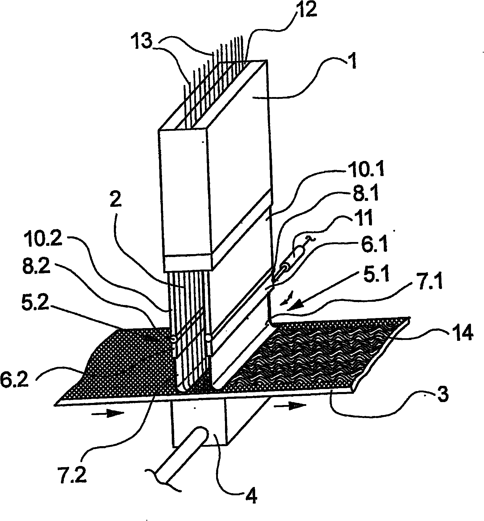
按图1的实施例示出一带一中间的纤维通道12的长方体形牵引喷嘴11。在纤维通道12内成排地引导多股纤维13。纤维13此前借助于一这里未示出的纺丝装置由合成聚合物熔体纺出。The exemplary embodiment according to FIG. 1 shows a
在牵引喷嘴1内在纤维通道12中输入压缩空气,从而将纤维13连续地从纺丝装置中抽出并将其输送到牵引喷嘴1的出口侧。在牵引喷嘴1的出口侧上设置一导引甬道2和一设置在导引甬道2端部处的铺放带3。导引甬道2具有两个相对的甬道壁10.1和10.2,所述甬道壁基本上平行于牵引喷嘴1的纤维通道12设置。这里甬道壁10.1和10.2最好密封地保持在牵引喷嘴1的出口侧上。Compressed air is fed into the
在导引甬道2的纵侧上,在甬道壁10.1和10.2的延长部中分别设置两个活门挡板5.1和5.2。这里活门挡板5.1和5.2分别由一支架6.1和6.2及与支架6.1和6.2可更换地连接的密封唇口7.1和7.2构成。支架6.1和6.2可分别通过摆动轴8.1和8.2改变其冲角。这里冲角是铺放带3和活门挡板5.1和5.2之间夹的角。密封唇口7.1和7.2设计成具有这样的弹性,即,使密封唇口7.1和7.2的下端与铺放带3或在铺放带3上被引导的无纺布14滑动接触,这里在导引甬道2内部在密封唇口7.1和7.2之间的铺放带3的区域称为铺放区。On the longitudinal sides of the
铺放带3与一这里未示出的驱动装置连接,通过该驱动装置可沿由箭头表示的输送方向引导铺放带3移动。铺放带3设计成透气的,从而牵引喷嘴1的气流可穿过铺放带3。为了输出和支持纤维铺放以形成无纺布在铺放带3的下侧上设置一抽吸装置4。其中抽吸装置4的抽吸作用限制在导引甬道2内部的铺放区内。The
图1中所示的实施例示出通过牵引喷嘴1连续地将纤维13输入纤维通道12并输送给铺放带3的运行状态。这时纤维13穿过导引甬道2。通过可在导引甬道2的纵侧上调整的活门挡板5.1和5.2,一方面相对于纵侧的周围环境密封铺放带3的铺放区,另一方面确定铺放区在铺放带3上的位置。为此保持在支架6.1和6.2上的密封唇口7.1和7.2弹性地贴靠在铺放带3和由铺放带3输送的无纺布14的表面上。通过密封唇口7.1和7.2与铺放带3及无纺布14之间的滑动接触在铺放区内在无纺布14整个宽度上防止吸入外界空气。纤维13仅在导引甬道2内的气流和抽吸作用下铺放。The exemplary embodiment shown in FIG. 1 shows an operating state in which
在图1所示的实施例中导引甬道2的端侧没有封闭。但是原则上也存在相对于周围环境密封地封闭导引甬道2的端侧的可能性。In the exemplary embodiment shown in FIG. 1 the
在按图1的实施例中,活门挡板5.1和5.2分别配设有调整机构11,通过所述调整机构可调整和改变导引甬道2端部处的冲角。但是原则上也存在用手动调整装置来对这种可运动地设置的活门挡板5.1和5.2进行定位的可能性。这里重要的是通过支架6.1和6.2进行调整。保持在支架6.1和6.2上的密封唇口7.1和7.2仅用来密封地贴靠在铺放带3和无纺布14上。In the exemplary embodiment according to FIG. 1 , the flaps 5 . 1 and 5 . 2 are each assigned an
在图2中以横向剖视图示意性示出按本发明的用来将合成纤维铺放成无纺布的装置的另一个实施例。按图2的实施例与上述实施例基本上相同,因此在下面的说明中仅仅解释其区别。为了铺放纤维13,在牵引喷嘴1和铺放带3之间调整到一比上述实施例小的铺放高度,为此牵引喷嘴1设计成高度可调的。A further exemplary embodiment of the device according to the invention for depositing synthetic fibers into a nonwoven is schematically shown in transverse section in FIG. 2 . The embodiment according to FIG. 2 is substantially identical to the above-described embodiment, so only the differences are explained in the following description. For depositing the
在本实施例中,设置在牵引喷嘴1和铺放带3之间的导引甬道2由两个相对设置的活门挡板5.1和5.2构成。活门挡板5.1具有一支架6.1,该支架可摆动地支承在摆动轴8.1上。摆动轴8.1安装在支座9的一保持元件15.1上。支座9安装在牵引喷嘴1的出口侧上。在支架6.1的自由端上可更换地固定一例如钢板形式的密封唇口7.1。这里这样确定密封唇口7.1的长度,即,使得密封唇口7.1的下端与铺放带3滑动接触。调整机构11.1作用在支架6.1上,通过该调整机构支架6.1可绕摆动轴8.1摆动。In this embodiment, the
活门挡板5.2通过支架6.2和密封唇口7.2布置在导引甬道2相对的纵侧上。支架6.2在摆动轴8.2上被引导,其中摆动轴8.2布置在保持元件15.2上。在支架6.2的自由端上可更换地固定一密封唇口7.2,该密封唇口以其自由端与在铺放带3上引导的无纺布14滑动接触,密封唇口7.2同样可以设计成例如具有0.2mm厚度的钢板。调整机构11.2作用在支架6.2上。通过该调整机构,所述支架可绕摆动轴8.2摆动和定位。The flap 5.2 is arranged on the opposite longitudinal side of the
支座9由相对的保持元件15.1和15.2构成。这里保持元件15.1和15.2设计成可水平移动的,从而导引甬道2在其宽度上可横向于纤维输送方向进行调整。The support 9 is formed by opposing holding elements 15.1 and 15.2. Here the holding elements 15.1 and 15.2 are designed to be displaceable horizontally, so that the width of the
在改变牵引喷嘴1和铺放带3之间的铺放高度时,可或者通过用相应地较短或较长的密封唇口更换密封唇口7.1和7.2,或者通过改变支架6.1和6.2的冲角来补偿导引甬道2的纵向位移
在铺放带3下方设置抽吸装置4。抽吸装置4具有可调整的抽吸口16,该抽吸口直接配设给铺放带3上的铺放区。这里抽吸口16在两个可移动地设置的盖板17.1和17.2之间形成。每块盖板17.1和17.2可相互相对水平移动。在盖板17.1和17.2和铺放带3之间形成一极小的抽吸缝隙18。抽吸缝隙18的尺寸这样选择,即,可以抽吸铺放带3上铺放区之外的外界空气。由此特别是在无纺布导引区内可以避免无纺布14从铺放带3抬起。因此可以取消沿无纺布14的输送方向进行附加的抽吸。为了只吸入尽可能少的和确定量的外界空气,抽吸缝隙18设计成可调整的,例如通过调整盖板17.1和17.2的高度来进行。A
图2中所示的实施例的功能和前面所述的实施例相同,因此可参照上面的说明。但是由于导引甬道2灵活的结构可以实现多种调整可能性,以得到特殊的长丝铺放,从而得到确定的无纺布,这里保持元件15.1和15.2、牵引喷嘴1、盖板17.1和17.2的调整运动可通过执行器自动进行,所述执行器例如可由一中央控制装置控制。因此存在根据规定的生产和过程参数进行对不同的调整环节进行自动调整的可能性。The function of the embodiment shown in Fig. 2 is the same as that of the previously described embodiment, so reference is made to the above description. However, due to the flexible structure of the
在图3至5中示出图2中所示装置的几个运行调整的变型方案。Several operational adjustment variants of the device shown in FIG. 2 are shown in FIGS. 3 to 5 .
例如可以这样来实现比较宽的铺放区,即如图3中所示,在分别向外摆动后保持活门挡板5.1和5.2。因此在铺放带3下侧相应较大的抽吸口16导致纤维在铺放时的扩展,由此形成较松散的无纺布。For example, a comparatively wide laying area can be achieved by holding the flaps 5.1 and 5.2 after each pivoting outward, as shown in FIG. 3 . Correspondingly
在图4中示出按图2的装置这样一种运行调整,其中活门挡板5.1和5.2在铺放带3上限定一较窄的铺放区,因此用相应较小的抽吸口16在铺放带3上形成较窄的铺放区。这时接近垂直于铺放带3铺放纤维13,从而由此可生产特别致密和牢固的无纺布。Shown in Fig. 4 is such a kind of running adjustment of the device according to Fig. 2, wherein the shutter baffles 5.1 and 5.2 limit a narrower laying area on the laying
图5中示意性示出图2中所示装置的运行调整的另一种可能性。这里在铺放带上产生较宽的铺放区,所述铺防区相对于牵引喷嘴出口端侧向错开设置。因此纤维以较平的角铺放在铺放带3上。A further possibility of operating adjustment of the device shown in FIG. 2 is schematically shown in FIG. 5 . This results in a relatively wide laying area on the laying belt, which is laterally offset relative to the outlet end of the pulling nozzle. The fibers are thus deposited on the
在图3至5中所示的运行调整仅示出本发明装置可能的调整方案的一种小的带宽。本发明装置所有的运行调整的共同之处在于,在纤维铺放时将外界空气影响减到最小。通过密封唇口7.1和7.2与铺放带3和无纺布14之间的滑动接触产生防止吸入外界空气的密封作用。因此导引甬道2的纵侧相对于周围环境基本上是封闭的。The operating adjustments shown in FIGS. 3 to 5 show only a small bandwidth of possible adjustment variants of the device according to the invention. Common to all operating settings of the device according to the invention is the minimization of external air influences during fiber laying. A sealing effect against the intake of outside air is produced by the sliding contact between the sealing lips 7.1 and 7.2 and the
图6以横向剖视图示意性示出另一个实施例。这里实施例仅示出铺放带的局部。这里未示出的构件与前面的实施例相同,因此这里不再详细说明。FIG. 6 schematically shows another embodiment in a transverse sectional view. The embodiments here only show a part of the laying tape. Components not shown here are the same as those in the previous embodiments, so they will not be described in detail here.
一方面为了按要求控制外界空气流入,另一方面为了实现对铺放带稳定的引导,在所示实施例中在铺放带3和设置在铺放带3下面的盖板17.1和17.2之间相互按一定间距设置多个间隔件19。所述间隔件19在朝向铺放带3的上侧具有倒圆部。为此间隔件19最好设计成具有半月形横截面,并作为横杆(Steg)基本上在铺放带3的整个宽度上延伸。从而确保相对于所形成的抽吸缝隙18支承和引导铺放带3。这里抽吸缝隙18通过间隔间19的下侧和盖板17.1和17.2之间的距离构成。在图6中抽吸缝隙18通过具有附图标记S的缝隙高度表示。缝隙高度最好调整到最大1mm至1.5mm。In order to control the inflow of external air as required on the one hand and to achieve a stable guidance of the deposit belt on the other hand, in the embodiment shown between the
在铺放带3下方这样来选择间隔件19之间的距离,即在抽吸口16两侧至少分别设置一个间隔件19。其中设置在抽吸口16两侧的间隔件19位于通过在铺放带3上方贴靠的密封唇口17.1和17.2构成的铺放区之内。此外,间隔件19设计成可更换的,以便可调整抽吸缝隙18不同的缝隙高度。The distance between the
因此本发明装置按图6的实施例的特征特别在于,只有少量外界空气从周围环境进入抽吸装置内。特别是在铺放侧这样选择抽吸缝隙,即可吸入足够的外界空气,以保证使无纺布牢固地贴靠在铺放带上。The embodiment of the device according to the invention according to FIG. 6 is therefore characterized in particular in that only a small amount of outside air enters the suction device from the surroundings. Especially on the laying side, the suction gap is selected in such a way that enough outside air can be sucked in to ensure that the non-woven fabric rests firmly on the laying belt.
在图1至6中所示的实施例在构件的结构和构型上是举例性的。因此本发明可扩展到所有类似的装置,在这些装置中,通过密封唇口保持导引甬道朝向铺放带的可运动的甬道壁与铺放带滑动接触。The exemplary embodiments shown in FIGS. 1 to 6 are exemplary in terms of structure and configuration of the components. The invention therefore extends to all similar devices in which the movable wall of the guide shaft towards the deposit belt is held in sliding contact with the deposit belt by means of a sealing lip.
按图1、2和6的实施例还可以这样修改,即还通过附加的屏蔽结构实现对端侧的屏蔽。因此这种屏蔽结构特别是在铺放带边缘处可影响无纺布的铺放。此外,可以实现附加的外界空气效应。The exemplary embodiment according to FIGS. 1 , 2 and 6 can also be modified in that the end-side shielding is also achieved by means of an additional shielding structure. Such a shielding structure can thus affect the laying of the nonwoven, especially at the edge of the laying belt. Furthermore, additional ambient air effects can be achieved.
还可以通过活门挡板或盖板的自动化执行器控制装置实现本发明装置的另一个变型方案。因此可以迅速和可再现地选择多个过程调整,以根据纤维和无纺布类型分别得到最佳的运行条件。A further variant of the device according to the invention can also be realized by means of an automated actuator control of the flap or cover. Multiple process adjustments can thus be selected quickly and reproducibly in order to obtain the respective optimum operating conditions depending on the type of fiber and nonwoven.
附图标记表Table of reference signs
1 牵引喷嘴 2 导引甬道1
3 铺放带 4 抽吸装置3 laying
5.1,5.2 活门挡板 6.1,6.2 支架5.1, 5.2 Valve baffle 6.1, 6.2 Bracket
7.1,7.2 密封唇口 8.1,8.2 摆动轴7.1, 7.2 Sealing lip 8.1, 8.2 Oscillating shaft
9 支座 10.1,10.2 甬道壁9 Support 10.1, 10.2 Corridor wall
11.1,11.2 调整机构 12 纤维通道11.1, 11.2
13 纤维 14 无纺布13
15.1,15.2 保持元件 16 抽吸口15.1, 15.2
17.1,17.2 盖板 18 抽吸缝隙17.1, 17.2
19 间隔件19 Spacer
Claims (13)
Applications Claiming Priority (3)
| Application Number | Priority Date | Filing Date | Title |
|---|---|---|---|
| DE102004046309.3 | 2004-09-24 | ||
| DE102004046309 | 2004-09-24 | ||
| PCT/EP2005/010308 WO2006032517A1 (en) | 2004-09-24 | 2005-09-23 | Device for stacking synthetic fibres to form a nonwoven |
Publications (2)
| Publication Number | Publication Date |
|---|---|
| CN101027442A CN101027442A (en) | 2007-08-29 |
| CN101027442B true CN101027442B (en) | 2010-06-16 |
Family
ID=35448363
Family Applications (1)
| Application Number | Title | Priority Date | Filing Date |
|---|---|---|---|
| CN2005800323204A Expired - Lifetime CN101027442B (en) | 2004-09-24 | 2005-09-23 | Device for laying synthetic fibers to form a nonwoven |
Country Status (5)
| Country | Link |
|---|---|
| US (1) | US8137088B2 (en) |
| EP (1) | EP1797230B1 (en) |
| CN (1) | CN101027442B (en) |
| DE (1) | DE502005006763D1 (en) |
| WO (1) | WO2006032517A1 (en) |
Families Citing this family (9)
| Publication number | Priority date | Publication date | Assignee | Title |
|---|---|---|---|---|
| US8246898B2 (en) * | 2007-03-19 | 2012-08-21 | Conrad John H | Method and apparatus for enhanced fiber bundle dispersion with a divergent fiber draw unit |
| JP5586620B2 (en) * | 2008-11-13 | 2014-09-10 | エーリコン テクスティル ゲゼルシャフト ミット ベシュレンクテル ハフツング ウント コンパニー コマンディートゲゼルシャフト | Equipment for producing spunbond nonwovens |
| JP5894598B2 (en) | 2010-08-12 | 2016-03-30 | ボマ エンジニアリング エス.ピー.エー. | Method and apparatus for producing fibers, in particular for producing fiber-containing nonwovens |
| EP2907909B1 (en) * | 2014-02-17 | 2017-08-09 | Reifenhäuser GmbH & Co. KG Maschinenfabrik | Assembly for the continuous production of a woven material |
| EP3129535B1 (en) | 2014-04-07 | 2018-03-21 | Boma Engineering S.P.A. | Process and apparatus for producing a fibrous- containing and/or particle-containing nonwoven |
| KR102340529B1 (en) * | 2015-09-03 | 2021-12-20 | 도레이 카부시키가이샤 | Manufacturing method and manufacturing apparatus of spunbond nonwoven fabric |
| CN109072519B (en) * | 2016-03-30 | 2021-10-01 | 三井化学株式会社 | Manufacturing apparatus of nonwoven fabric and manufacturing method of nonwoven fabric |
| CA3058347C (en) | 2017-03-27 | 2023-04-11 | Sellars Absorbent Materials, Inc. | Absorbent laminated material |
| ES2886885T3 (en) * | 2019-07-30 | 2021-12-21 | Reifenhaeuser Masch | Device and method for the manufacture of a nonwoven material from fibers |
Citations (5)
| Publication number | Priority date | Publication date | Assignee | Title |
|---|---|---|---|---|
| US2460899A (en) * | 1944-08-30 | 1949-02-08 | Johns Manville | Method of mat formation |
| EP0150024A2 (en) * | 1984-01-19 | 1985-07-31 | Hoechst Aktiengesellschaft | Apparatus for the manufacture of a spun-bonded fabric |
| DE3740893A1 (en) * | 1987-04-25 | 1988-11-10 | Reifenhaeuser Masch | Spun-bonded web apparatus for producing a spun-bonded web from synthetic endless filament |
| CN2208580Y (en) * | 1994-12-01 | 1995-09-27 | 张国芳 | Swing type lapping machine |
| US6379136B1 (en) * | 1999-06-09 | 2002-04-30 | Gerald C. Najour | Apparatus for production of sub-denier spunbond nonwovens |
Family Cites Families (6)
| Publication number | Priority date | Publication date | Assignee | Title |
|---|---|---|---|---|
| SE327078B (en) * | 1968-03-07 | 1970-08-10 | Defibrator Ab | |
| GB1581171A (en) * | 1976-04-08 | 1980-12-10 | Bison North America Inc | Alignment plate construction for electrostatic particle orientation |
| DE4312419C2 (en) * | 1993-04-16 | 1996-02-22 | Reifenhaeuser Masch | Plant for the production of a spunbonded nonwoven web from aerodynamically stretched plastic filaments |
| DE19620379C2 (en) * | 1996-05-21 | 1998-08-13 | Reifenhaeuser Masch | Plant for the continuous production of a spunbonded nonwoven web |
| DE19940333B4 (en) * | 1999-08-25 | 2004-03-25 | Reifenhäuser GmbH & Co Maschinenfabrik | Plant for the production of a spunbonded nonwoven web from plastic filaments |
| EP1340842B2 (en) * | 2002-02-28 | 2010-12-08 | Reifenhäuser GmbH & Co. KG Maschinenfabrik | Apparatus for the continued production of a spunbonded web |
-
2005
- 2005-09-23 CN CN2005800323204A patent/CN101027442B/en not_active Expired - Lifetime
- 2005-09-23 DE DE502005006763T patent/DE502005006763D1/en not_active Expired - Lifetime
- 2005-09-23 US US11/575,843 patent/US8137088B2/en active Active
- 2005-09-23 EP EP05797780A patent/EP1797230B1/en not_active Expired - Lifetime
- 2005-09-23 WO PCT/EP2005/010308 patent/WO2006032517A1/en not_active Ceased
Patent Citations (5)
| Publication number | Priority date | Publication date | Assignee | Title |
|---|---|---|---|---|
| US2460899A (en) * | 1944-08-30 | 1949-02-08 | Johns Manville | Method of mat formation |
| EP0150024A2 (en) * | 1984-01-19 | 1985-07-31 | Hoechst Aktiengesellschaft | Apparatus for the manufacture of a spun-bonded fabric |
| DE3740893A1 (en) * | 1987-04-25 | 1988-11-10 | Reifenhaeuser Masch | Spun-bonded web apparatus for producing a spun-bonded web from synthetic endless filament |
| CN2208580Y (en) * | 1994-12-01 | 1995-09-27 | 张国芳 | Swing type lapping machine |
| US6379136B1 (en) * | 1999-06-09 | 2002-04-30 | Gerald C. Najour | Apparatus for production of sub-denier spunbond nonwovens |
Also Published As
| Publication number | Publication date |
|---|---|
| US20080317895A1 (en) | 2008-12-25 |
| DE502005006763D1 (en) | 2009-04-16 |
| WO2006032517A1 (en) | 2006-03-30 |
| US8137088B2 (en) | 2012-03-20 |
| EP1797230A1 (en) | 2007-06-20 |
| CN101027442A (en) | 2007-08-29 |
| EP1797230B1 (en) | 2009-03-04 |
Similar Documents
| Publication | Publication Date | Title |
|---|---|---|
| CN101027442B (en) | Device for laying synthetic fibers to form a nonwoven | |
| US8827673B2 (en) | Device for dry-forming a fibrous web | |
| US8231370B2 (en) | Apparatus and method for depositing synthetic fibers to form a non-woven web | |
| CZ2003583A3 (en) | Apparatus for continuous production of a non-woven web | |
| JP3242959B2 (en) | Equipment for forming fiber fleece from synthetic fibers, cotton, swoosh, etc. | |
| JP4410400B2 (en) | Equipment for producing spunbonded nonwoven fabric made of synthetic resin filaments | |
| US20040009251A1 (en) | Apparatus for producing melt-blown webs | |
| US12540422B2 (en) | Machines systems and methods for making random fiber webs | |
| US20080256757A1 (en) | Apparatus and method for depositing synthetic fibers to form a nonwoven | |
| JP4444449B2 (en) | Apparatus for forming a fleece from a cotton lump having a substantially vertical hollow cylinder of at least one rectangular cross section | |
| EP1354988B1 (en) | Carding machine with air jet doffer | |
| JP4541480B2 (en) | Device for supplying floc fibers to a floc storage device | |
| US6729465B2 (en) | Plant and a method for transporting textile fabrics | |
| JP7580529B2 (en) | Machine system and method for producing random fiber webs - Patents.com | |
| CN216864492U (en) | Non-woven fabric net forming device | |
| RU39602U1 (en) | DEVICE FOR FORMING FIBROUS FLOORS | |
| DK155441B (en) | Apparatus and process for producing fibre webs |
Legal Events
| Date | Code | Title | Description |
|---|---|---|---|
| C06 | Publication | ||
| PB01 | Publication | ||
| C10 | Entry into substantive examination | ||
| SE01 | Entry into force of request for substantive examination | ||
| ASS | Succession or assignment of patent right |
Owner name: ALBIS CO., LTD. Free format text: FORMER OWNER: OERLIKON TEXTILE GMBH + CO. KG Effective date: 20100426 |
|
| C41 | Transfer of patent application or patent right or utility model | ||
| COR | Change of bibliographic data |
Free format text: CORRECT: ADDRESS; FROM: REMSCHEID, GERMANY TO: MILAN, ITALY |
|
| TA01 | Transfer of patent application right |
Effective date of registration: 20100426 Address after: Milan Italy Applicant after: Albis Co.,Ltd. Address before: Remscheid Applicant before: OERLIKON TEXTILE GmbH & Co.KG |
|
| C14 | Grant of patent or utility model | ||
| GR01 | Patent grant | ||
| ASS | Succession or assignment of patent right |
Owner name: ALBIS INTERNATIONAL S. R. L Free format text: FORMER OWNER: ALBIS CO., LTD. Effective date: 20140704 |
|
| C41 | Transfer of patent application or patent right or utility model | ||
| TR01 | Transfer of patent right |
Effective date of registration: 20140704 Address after: Milan Italy Patentee after: Albis International Ltd. Address before: Milan Italy Patentee before: Albis Co.,Ltd. |
|
| CX01 | Expiry of patent term |
Granted publication date: 20100616 |
|
| CX01 | Expiry of patent term |